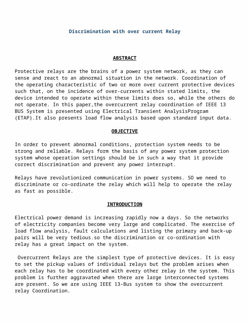
Discrimination with over current Relay ABSTRACT Protective relays are the brains of a power system network, as they can sense and react to an abnormal situation in the network. Coordination of the operating characteristic of two or more over current protective devices such that, on the incidence of over-currents within stated limits, the device intended to operate within these limits does so, while the others do not operate. In this paper,the overcurrent relay coordination of IEEE 13 BUS System is presented using Electrical Transient AnalysisProgram (ETAP).It also presents load flow analysis based upon standard input data. OBJECTIVE In order to prevent abnormal conditions, protection system needs to be strong and reliable. Relays form the basis of any power system protection system whose operation settings should be in such a way that it provide correct discrimination and prevent any power interrupt. Relays have revolutionized communication in power systems. SO we need to discriminate or co-ordinate the relay which will help to operate the relay as fast as possible. INTRODUCTION Electrical power demand is increasing rapidly now a days. So the networks of electricity companies become very large and complicated. The exercise of load flow analysis, fault calculations and listing the primary and back-up pairs will be very tedious.so the discrimination or co-ordination with relay has a great impact on the system. Overcurrent Relays are the simplest type of protective devices. It is easy to set the pickup values of individual relays but the problem arises when each relay has to be coordinated with every other relay in the system. This problem is further aggravated when there are large interconnected systems are present. So we are using IEEE 13-Bus system to show the overcurrent relay Coordination.

Relay Co Ordination
Dec 21, 2015
gdsf
Welcome message from author
This document is posted to help you gain knowledge. Please leave a comment to let me know what you think about it! Share it to your friends and learn new things together.
Transcript
Discrimination with over current Relay
ABSTRACT
Protective relays are the brains of a power system network, as they can sense and react to an abnormal situation in the network. Coordination of the operating characteristic of two or more over current protective devices such that, on the incidence of over-currents within stated limits, the device intended to operate within these limits does so, while the others do not operate. In this paper,the overcurrent relay coordination of IEEE 13 BUS System is presented using Electrical Transient AnalysisProgram (ETAP).It also presents load flow analysis based upon standard input data.
OBJECTIVE
In order to prevent abnormal conditions, protection system needs to be strong and reliable. Relays form the basis of any power system protection system whose operation settings should be in such a way that it provide correct discrimination and prevent any power interrupt.
Relays have revolutionized communication in power systems. SO we need to discriminate or co-ordinate the relay which will help to operate the relay as fast as possible.
INTRODUCTION
Electrical power demand is increasing rapidly now a days. So the networks of electricity companies become very large and complicated. The exercise of load flow analysis, fault calculations and listing the primary and back-up pairs will be very tedious.so the discrimination or co-ordination with relay has a great impact on the system.
Overcurrent Relays are the simplest type of protective devices. It is easy to set the pickup values of individual relays but the problem arises when each relay has to be coordinated with every other relay in the system. This problem is further aggravated when there are large interconnected systems are present. So we are using IEEE 13-Bus system to show the overcurrent relay Coordination.
In order to provide adequate protection for the circuit, the fault conditions must be simulated and analyzed. This can be done using software from Operation Technology, Inc. called ETAP. ETAP is comprehensive software that allows the user to design and simulate power systems as well as automate generation, transmission, and distribution schemes.
The goal of this project is to analyze the mentioned system and determine protective device coordination to achieve optimum equipment protection and selectivity.
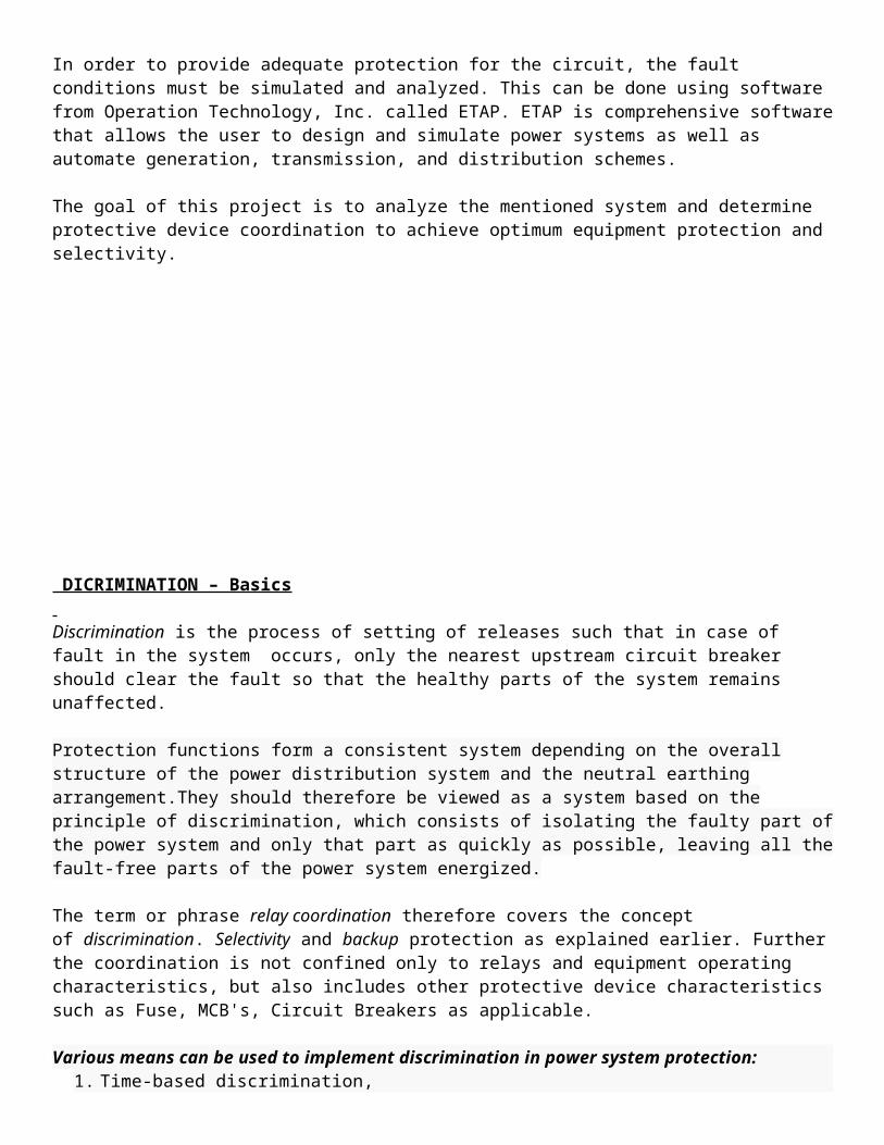
DICRIMINATION – Basics Discrimination is the process of setting of releases such that in case of fault in the system occurs, only the nearest upstream circuit breaker should clear the fault so that the healthy parts of the system remains unaffected.
Protection functions form a consistent system depending on the overall structure of the power distribution system and the neutral earthing arrangement.They should therefore be viewed as a system based on the principle of discrimination, which consists of isolating the faulty part of the power system and only that part as quickly as possible, leaving all the fault-free parts of the power system energized.
The term or phrase relay coordination therefore covers the concept of discrimination. Selectivity and backup protection as explained earlier. Further the coordination is not confined only to relays and equipment operating characteristics, but also includes other protective device characteristics such as Fuse, MCB's, Circuit Breakers as applicable.
Various means can be used to implement discrimination in power system protection:1. Time-based discrimination,2. Current-based discrimination,3. Discrimination by data exchange, referred to as logic discrimination,4. Discrimination by the use of directional protection functions,5. Discrimination by the use of differential protection functions,6. Combined discrimination to ensure better overall performance (technical, economic), or back-up.
DEGREES of DISCRIMINATION
Discrimination may be total or partial, and based on the principles of current levels, or time-delays, or a combination of both.
Discrimination between circuit-breakers A and B is total if the maximum value of short-circuit-current on circuit B (Isc B) does not exceed the short-circuit trip setting of circuit-breaker A (Im A). For this condition, B only will trip.
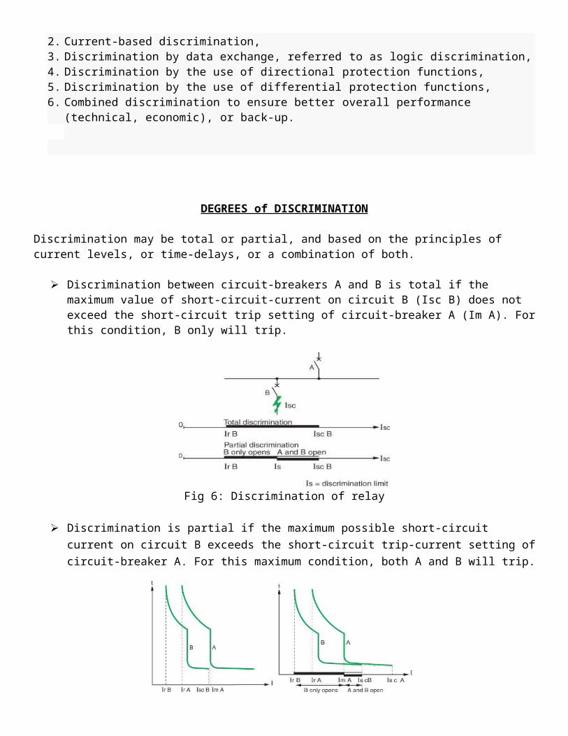
Fig 6: Discrimination of relay
Discrimination is partial if the maximum possible short-circuit current on circuit B exceeds the short-
circuit trip-current setting of circuit-breaker A. For this maximum condition, both A and B will trip.
Fig 7: Total and Partial discrimination
11
DIFFERENT TECHNIQUES to ACHIVE DISCRIMINATION
Various means can be used to implement discrimination in power system protection:
Time discrimination
Current discrimination
Energy discrimination
Zone (logical) discrimination
1. TIME DICRIMINATION:
Time based discrimination is the process of setting different time delays in the protection releases (over
current or short circuit or earth fault) of various circuit breakers distributed throughout the system.
Here Discrimination is done among devices with different trip time settings in order to avoid
overlapping areas and Setting different device trip delays for different hierarchical levels.
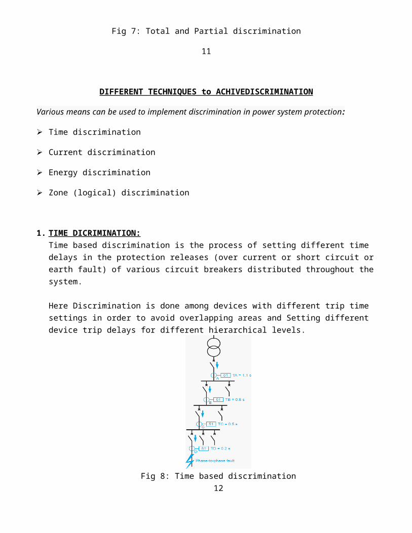
Fig 8: Time based discrimination
12
The fault shown in the diagram opposite (fig. 7) is detected by all the protection units (at A, B, C, and D). The contacts of delayed protection unit D close faster than those of protection unit C, which themselves close faster than those of protection unit B…Once circuit breaker D tripped and the fault current has been cleared, protection units A, B and C, which are no longer required, return to the stand-by position. The difference in operation time DT between two successive protection units is the discrimination interval.
It takes into account (fig. 8): Breaking time Tc of the downstream circuit breaker, which includes the breaker response time and the
arcing time, Time delay tolerances dT, Upstream protection unit overshoot time: tr, A safety margin m.
Fig 9: Breakdown of a discrimination interval
ΔT should therefore satisfy the relation:
ΔT ≥ Tc + tr + 2dT + m

EXAMPLE: Tc = 95 ms, dT = 25 ms, tr = 55 ms; for a 300 ms discrimination interval, the safety margin is 100 MS.
Advantages of Time-based Discrimination:
1. It provides its own back-up; for example if protection unit D fails, protection unit C is activated ΔT later.
It is simple. Disadvantages of Time-based Discrimination:
1. The relay will operate only after the set time delay, irrespective of the location of the fault.
2. CURRENT DICRIMINATION:
In current based discrimination the pickup current setting of the immediate upstream circuit breaker
short time release is set above the fault level at the downstream circuit breaker.
Fig 10: Current based discrimination
For example in fig 9 for a fault E, the circuit breaker D ,the instantaneous release pickup setting is set at a level below 3000A. Circuit breaker D will detect this fault and isolate the faulty section.14To achieve current based discrimination, the pickup current setting instantaneous release of circuit breaker C has to be set above 3000A, which is the fault level at E, but bellow 6000A, which is the fault level at F. Similarly the pickup current setting instantaneous release of circuit breaker B has to be set above 6000A which is the fault level at F, but below 9000A, which is the fault level at G. So also, the
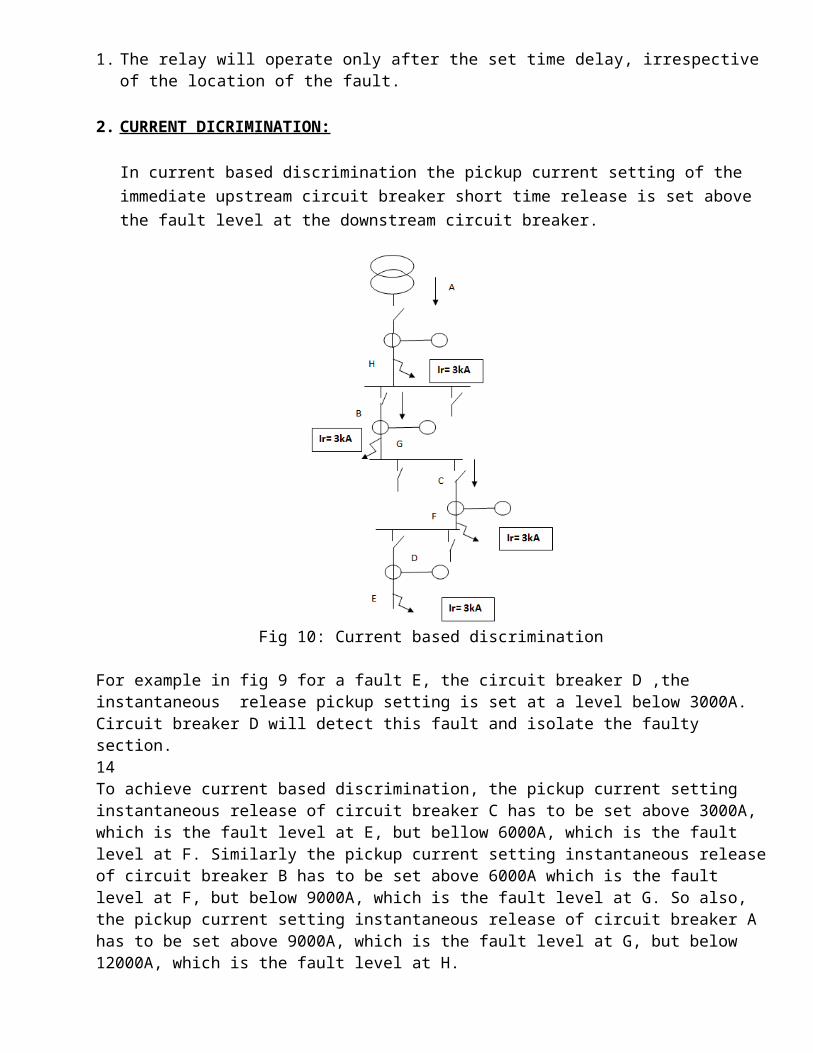
pickup current setting instantaneous release of circuit breaker A has to be set above 9000A, which is the fault level at G, but below 12000A, which is the fault level at H.
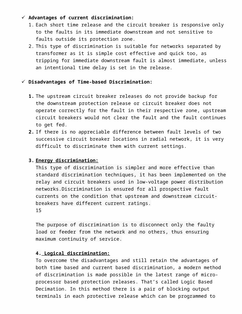
Advantages of current discrimination:
1. Each short time release and the circuit breaker is responsive only to the faults in its immediate
downstream and not sensitive to faults outside its protection zone.
2. This type of discrimination is suitable for networks separated by transformer as it is simple cost
effective and quick too, as tripping for immediate downstream fault is almost immediate, unless an
intentional time delay is set in the release.
Disadvantages of Time-based Discrimination:
1. The upstream circuit breaker releases do not provide backup for the downstream protection release
or circuit breaker does not operate correctly for the fault in their respective zone, upstream circuit
breakers would not clear the fault and the fault continues to get fed.
2. If there is no appreciable difference between fault levels of two successive circuit breaker locations
in radial network, it is very difficult to discriminate them with current settings.
3. Energy discrimination:
This type of discrimination is simpler and more effective than standard discrimination techniques,
it has been implemented on the relay and circuit breakers used in low-voltage power distribution
networks.Discrimination is ensured for all prospective fault currents on the condition that
upstream and downstream circuit-breakers have different current ratings.
15
The purpose of discrimination is to disconnect only the faulty load or feeder from the network and
no others, thus ensuring maximum continuity of service.
4. Logical discrimination:
To overcome the disadvantages and still retain the advantages of both time based and current based
discrimination, a modern method of discrimination is made possible in the latest range of micro-
processor based protection releases. That’s called Logic Based Decimation. In this method there is a
pair of blocking output terminals in each protective release which can be programmed to operate for
any or all of the types of fault that the release is protecting against.
SYSTEM MODEL
1. IEEE 13 BUS SYSTEM:
Fig 11: IEEE 13 BUS system
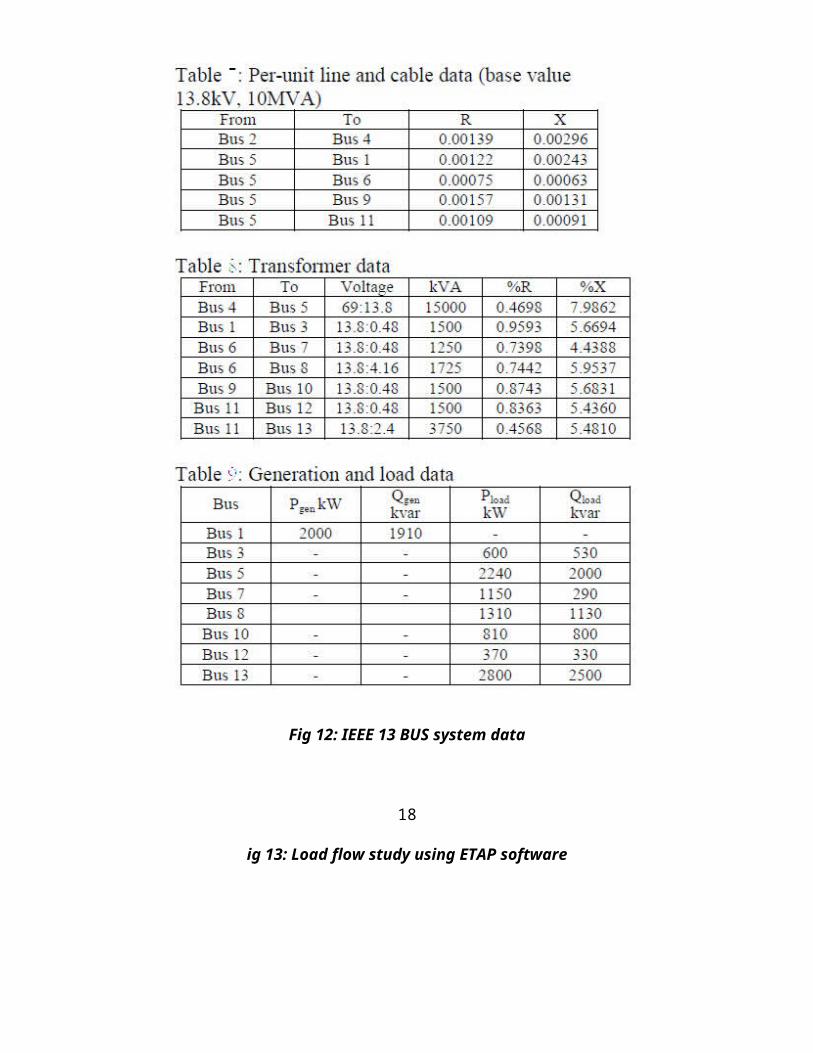
2. SYSTEM DATA:
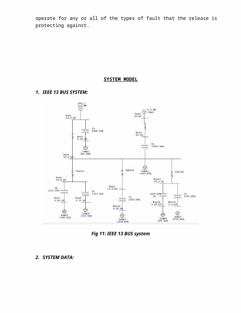
Fig 12: IEEE 13 BUS system data
18
ig 13: Load flow study using ETAP software
19
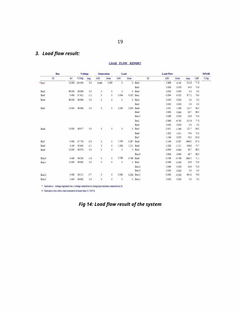
3. Load flow result:
Fig 14: Load flow result of the system
20
CHAPTER 12
FUTURE SCOPEof STUDY
1. More accurate fault handling by relay co-ordination.
2. Efficient primary and backup protection.
3. Study on effect of harmonics on overall operation of relay.
4. Troubleshooting false trips, relay mis-operation, and mis-coordination.
5. AC & DC coordination.
6. Modeling of multi-function & multi-level relays.
7. Combination of current, time and logic based discrimination.
21
CHAPTER 13
CONCLUSION
Theoretical and experimental analyses of this paper have shown the influence of discrimination of overcurrent relays. We choose a standard IEEE 13 bus system and then study the load flow analysis and it gives us proper results so the system we choose is in normal condition where any faults is not present. Now in the system we can study the relay discrimination by adding a fault condition to the system.
22
CHAPTER 14
REFERENCE AND BIBLIOGRAPHY
• K. Sivkumar, manager training Larsen and Toubro( Electrical India magazine,page:41-45)
• 7th WSEAS International Conference on Electric Power Systems, High Voltages, Electric Machines,
Venice, Italy, November 21-23, 2007 paper.
• Power System Protection Studies and Relay Coordination (http://www.powerapps.org/Power
%20System%20Protection%20Studies%20and%20Relay%20Coordination.aspx)
• Isolating the Fault With Time-based Discrimination (http://electrical-engineering-portal.com/isolating-
the-fault-with-time-based-discrimination)
• Relay information (http://en.wikipedia.org/wiki/Protective_relay).
• Relay pictures (http://www.circuitstoday.com/working-of-relays).
• Etap.com for load flow and co-ordination study.
----END---
23
Related Documents