91-0522-458500 I~' ~"1\31 _~RAILMANAK·. Lucknow 451200 (PBX) 450567 (DID) ~rr@trfcfiR - m rfm:rq ~ ~~ ~ 1iHcf> Wro:r ~- 226011 Government of India-Ministry of Railways Research Designs & Standards Organisation Lucknow - 226011 A::::c-:.i::ej by C"'",~ R.•:. !SO.'.\:»)\ REGISTERED ORGN.y,T"·: O~N ~~lfQn av TH€ ~~:--."t:::-~J..': No. (1)3.2.19 Dakd 21 .06.2001 Chief E lectrical Engineer, - Central Railway, ~lumbai CST- -1-0000l. - Eastern Railway, Fairlie Place, Kolkata - 700 001 - East Coast Railway, Chandrashekharpur, Bhubaneshwar- 751 001. - East Central Railway, Hazipur, Dichi (Bihar) - Northern Railway, Baroda House, New DeUli-110 001 - North - Eastern Railway, Gorakhpur - 272 601. - Northeast frontier Railway, Maligaon, Guwahati - 781 011 - North Central Railway, Hasting Road, Allahabad-Zl l 001. - North West Railway, Jaipur ( Rajasthan) . - Southern Railway, Park Town, Chcnnai-out) 003 - South Central Railway.vRail Nilayam, Secunc1erabac\-500 371 - South Eastern Railway, Garden Reach, Kolkata -700 043 - South Western Railway, Bangalorc - 560 046 - Western Railway, Churchgatc, Mumbai -400 020 - West Central Railway, Jabalpur, - New Zone Railway, Bilaspur. - Chittaranjan Locomotive Works, Chittaranjan- 713 331 spr~CIALl\-JAINTENANCE TNSTRUCTIONNO. I~LRS/SrvII/Ol97-2001, REV. '1' \ (Note: This S!VII supersedes RDSO's SM1 No. SIHIIl97 & S1\-11No. 190.) 1. Title: Driving technique and use of proportionate brake application to prevent cases of wheel skidding on dual brake as well JS pure air brake electric locomotives. 2. Brier History: 2.1 Earlier application of braking force on train than on the locomotive results in skidding of the wagons and tensioning of locomotive coupling as locomotive keep on dragging the braked wagons. On the other hand, earlier braking force on locomotive thanon the train results in the ramming of the train against the locomotive resulting in the locomotive's wheel skidding. In order to avoid both the above situations, it becomes necessary to synchronize the brake application on both the train Jnc!-ilic locomotive. Accordingly, a provision has been made in the C3 \\' distrr1'Gutor valve for proportionate brake application on locomotive whenever brake application on [rain is made through A9. Also, for judicious application of brakes on locomotive in order to avoid allY of the situation described above, J paddle switch called rVEf i13S been provided rye.: I DJ 0

Welcome message from author
This document is posted to help you gain knowledge. Please leave a comment to let me know what you think about it! Share it to your friends and learn new things together.
Transcript
91-0522-458500I~' ~"1\31_~RAILMANAK·. Lucknow451200 (PBX)450567 (DID)
~rr@trfcfiR - m rfm:rq~ ~~ ~ 1iHcf> Wro:r
~- 226011Government of India-Ministry of Railways
Research Designs & Standards OrganisationLucknow - 226011
A::::c-:.i::ejby C"'",~R .• :.
!SO.'.\:»)\ REGISTERED ORGN.y,T"·:O~N ~~lfQn av TH€ ~~:--."t:::-~J..':
No. (1)3.2.19 Dakd 21 .06.2001
Chief E lectrical Engineer,- Central Railway, ~lumbai CST- -1-0000l.- Eastern Railway, Fairlie Place, Kolkata - 700 001- East Coast Railway, Chandrashekharpur, Bhubaneshwar- 751 001.- East Central Railway, Hazipur, Dichi (Bihar)- Northern Railway, Baroda House, New DeUli-110 001- North - Eastern Railway, Gorakhpur - 272 601.- Northeast frontier Railway, Maligaon, Guwahati - 781 011- North Central Railway, Hasting Road, Allahabad-Zl l 001.- North West Railway, Jaipur ( Rajasthan) .- Southern Railway, Park Town, Chcnnai-out) 003- South Central Railway.vRail Nilayam, Secunc1erabac\-500 371- South Eastern Railway, Garden Reach, Kolkata -700 043- South Western Railway, Bangalorc - 560 046- Western Railway, Churchgatc, Mumbai -400 020- West Central Railway, Jabalpur,- New Zone Railway, Bilaspur.- Chittaranjan Locomotive Works, Chittaranjan- 713 331
spr~CIALl\-JAINTENANCE TNSTRUCTIONNO. I~LRS/SrvII/Ol97-2001, REV. '1'
\(Note: This S!VII supersedes RDSO's SM1 No. SIHIIl97 & S1\-11No. 190.)
1. Title:
Driving technique and use of proportionate brake application to prevent cases ofwheel skidding on dual brake as well JS pure air brake electric locomotives.
2. Brier History:
2.1 Earlier application of braking force on train than on the locomotive results inskidding of the wagons and tensioning of locomotive coupling as locomotivekeep on dragging the braked wagons. On the other hand, earlier braking force onlocomotive thanon the train results in the ramming of the train against thelocomotive resulting in the locomotive's wheel skidding.
In order to avoid both the above situations, it becomes necessary to synchronizethe brake application on both the train Jnc!-ilic locomotive. Accordingly, aprovision has been made in the C3 \\' distrr1'Gutor valve for proportionate brakeapplication on locomotive whenever brake application on [rain is made throughA9. Also, for judicious application of brakes on locomotive in order to avoid allYof the situation described above, J paddle switch called rVEf i13S been provided
rye.: IDJ 0
· \In driver's cab for the driver to press and release synchronized brakes em th, \locomotive. as per the requirement. Para No. 30645 of ACTM Vol. II: also \specifies for the driver to ensure pressing of PVEF paddle switch while applyingtrain brakes whenever he experiences poor brake power of the train, in order toavoid wheel skidding oflocomotive's wheels due to ramming of the train againstthe locomotive,
2.2 The setting of 'RGEB' in dual brake locomotives had been advised in the pas t asfollows;
NiC contact ofRGED should open from 4,2 kg/em:! of DP pressure duringbrake application.---
--------N/C contact of RGEB should close from 2.8 kg/en.' of B_P_ pressureduring brake release.
In dual brake locomotives, RGEB is activated by IvLRpressure coi-ning throughH5!.f-IDS pneumatic valves on getting the pneumatic signal from A9iV ;\'113, as thecase may be. The direct settings of RGEB, HS as well as In~) ;!l terms of MEpressure, D,P. pressure and vacuum level have been specified in NmCXLII-(:- I 0['
RDSO's, 'Miscellaneous Report No. NlP.Misc.- 4S' of July 1996. Therefore,there is no meaning of indirect setting of RGEB as given above. It i::: also .1;)\':;(:
that setting of HS valve for cut out of RGEB, is very much OIl tile lower side :-iscompared to indirect cut out setting of RGEB which is specified as :L2 l':g!i.'T,lAs a result, as and when automatic brakes are being applied from A9 m elidbrake locomotive, N/C contact of RGEB in the circuit of QRS gets opened at 4:~kg/cm'' of B.P. pressure making 'VEF' ineffective as N/O contact of QR;-~ in 111<:'VE[<"circuit also opens simultaneously. Under such conditions, if lo:«l i~0:-poor brake power, continuous ramming of train against the locomotive will takeplace as driver will not be able to isolate the locomotive brakes tlu ough pac1dkswitch 'PVEF'.
2.3 Railways have been asking clarifications on piston stroke of brake cylinder forvarious types of locomotives as well as traction motor current en which 10;:0
should or should not move after full brake application through A9.
3. Application :
Locomotives provided with IRAVB2 and IRAB2 brakesystem.
4. Object:
This Sl\'U deals with the preventive measures as well ,':; checklist I(] io·-,'.:stigai0the cases of locomotives' wheel skidding and to rninimise them

5. Instructions:
i) Brake cylinder pressure in locomotive should not be more than 2.5 kg/em:at full application position of A9. However. brake cylinder pressurecorresponding to full application position of SA9 should remain at 3.5koicm2
='
ii) Brake application as well as release timings should be as follows;
(Rcf: Motive Power Directorate's letter No. SD.DE,\l.IRA VB-2dated 19/22.9.88 )
(A) For Passenger Carrying Services:
(a) Brake armlication time 6 to 9 seconds for 95~b ofmaximum pressure build up.
(b) Brake release time 10 to 15 seconds for brakecylinder pressure reductionupto 0.4 kg/cm '.
(B) For Goods Services:
(a) Drake agplication time 20 to 25 seconds for 95% ofmaximum pressure build up.
(b) Drake release time 25 to 30 seconds for brakecylinder pressure reduction
?upto 0.4 kg/ern".
NOTE:The 'goods' as well as 'passenger' position of handle provided on C3Wvalve should be clearly marked and drivers/trip shed staff/maintenancestaff should be counselled properly.
iii) The hardness of the brake blocks should be randomly checked every timea new supply is received. The hardness should invariably be between 160-220 BHN.
iv) The brake power of the locomotive should be checked in the followingmanner;
Apply full brakes using SA9. The brake cylinder pressure gaugesh.oule! indicate a reading of 3.5 kg/ern' under such condition.

Take notches through .lvlP and record the observations as per tablegiven below;
\
7. WAG7 16:65 600 8008. WAG7 18:64 600 800
\,~I.Type of Gear Traction motor I Traction motorI N. ,Loco Ratio current at which I current at! I loco should not I which loco\ I move should move,-j~H 15:62 600 800f 2. I WA1\!i4 21:58 800 1000I 3. i W AG5 15:62 GOO 800~--j -- ----. ------------- -----_._----I 4 . .J....... WAGS 18:64 GOO 800-5~ I'\V;V;-l - 21:58 800 1006---6. WAP4 23:58 800 1000
--
NOTE:
The above valves have been calculated theoretically from the loco characteristics.During practical working, there may be a variation of ± 50 Amps.
v) Check the piston travel of all brake cylinders and free movement of wheelin brake released condition. The specified valve of brake cylinder pistonstroke for different types of locomotives in their respective MP/Mfs is asfellows;
r~~IT~p~rio;;-1'~~gi: ---- ---------------1of Brake Shoe Specified References .release for pistonwhich piston stroke
I stroke has I
been I Ispecified--~
I1. WAM4/W AG51 Co-Co 10mm 95-105 mm RDSO's Instruction i
WCAl\H/WCG2 trimount I3ulletin N0'1...[l.AP.IB.VL.Ol.04.0l, I
- r- \ (Rev. 0.00).2. \VAPI/WAP4 Flexi coil 6mm 50mm I Para 3.l.2.2 of I\.1P.IVl~
mark I ( zq~rClx.) I 90/80.3. WAG7 High 6mm 67mm I Para 1.4.5 Cd) ofl
adhesion (approx ) VL.i\·rr 01/96 of Nov.L_-L-______ bogie I '96. !

11i/r
-.'-'.
NOTE:I. TIle measurement of piston stroke length should be done only after placing
distance pieces of specified thickness between wheel tread and brakeblock.
2. The piston stroke length is a function of brake shoe release and totalleverage of brake rigging. The increase of 1 rnm brake shoe release willincrease piston stroke length by 10 mrn, 6 mm and 11 mm inWAIvf4fWAG5, WAPI/W AP4 ,and WAG7 class of locomotivesapproximately.
vi) The setting of RGEB, H5 and ,f-illS in dual brake locos must be ensured asfollows; ,
c-"oNol Type of Valve Setting I Reference1. RGEI3 Cut out - (7.5 ± 0.1) Kg/emz Annexure-I of RDSO's
Cut in - (6.5 ± 0.1) Kg/ern' ' T\1isc. Report No.1vfP Jviise.- 45 of July'96.
b: H5* Cut in - (1.9 ± 0.1) Kglcm- -do-Cut out- (2.4-2.8) Kg/ern"
"-3...:_, I-IB5 360-410 mrn of Hg. -clo-
>1< In dual brake locomotives being provided with modification for automaticoperation of flahser light, H5 valve will get replaced with RGEB2 directlymounted on DP pipe.
vii) The regression of power through H5 as- well as I-illS valve should betcs teel as follows;
Charge the brake pipe by keeping A9 automatic brake valve handle inrelease position. Put HVSI 1 & 2 and ,HVivff 1 & 2 on position '0' andtake 2-3 notches. Reduce the brake pipe pressure by A9 brake valve,When the BP pressure drops to 1.9 +0.2 kg/em", regression of GR
- 0.0should take place. Progression of GR should again be possible onlywhen BP is restored to 2.4 -'2.8 kg/ern'.
\
, fIBS Relay Air Valve: ,
Charge the brake pipe by keeping A9 automatic brake valve handle inrelease position. With HVSI 1 & 2 and HV!\:fT 1 & 2 on position '0',take 2-3 notches. Now lift D 1 emergency brake valve lever partially
PO(f- '5 of- 8

ensuring that only vacuum in train pipe drops slowly and does not permitBP pressure to drop. Alternatively, vacuum train pipe on either end ofthe loco may be lessened on its dummy plug. Regression of GR shouldtake place when vacuum level drops. between 360-410 nun. Progressionof GR should again be possible only when vacuum level is restored back.
viii) The setting of RGEB in pure air brake locos must be ensured as follows ;
Cut out - 2.5 Kg/cm:!Cut in - 4.2 Kg/ern'
ix) The working of 'VEF' valve through paddle switch 'PVFP should bechecked during every trip inspection as well as schedule/unschcdule visitof the locomotives to the Shed.
In the MU formation, no indication of 'VEF' working in the rear loco isavailable in the driving cab of leading loco. Therefore while doingpneumatic testing in the multiple formation, simultaneous 'VEF'working in both the locos should be physically verified.
x) Drivers 'should be counseled for judicious use of 'PVEF' while applyingthe brakes in the train that is whenever he takes the control of t~H~train, heshould check up the brake power of the train by partially applying thebrakes before the first block section. If he feels that the brake power ofthe train is satisfactory, he should not resort to apply 'PVEF' whileapplying brakes through ;\9: In ease he feels otherwise, then cm1y heshould use 'PVEF'.
xi) Trials conducted by RDSO in the past have proved that synchronizedproportionate brake application on locomotive is not responsible forlocomotive's wheel skidding in case of brake application on loud throughA9 up to proportionate brake cylinder pressure of 3.S kg/ern? inlocomotive. The skidding oflocomotive's wheels do take place if train isstopped using only loco brake i.e. SA9 even from a speed of 10-20 kmph.
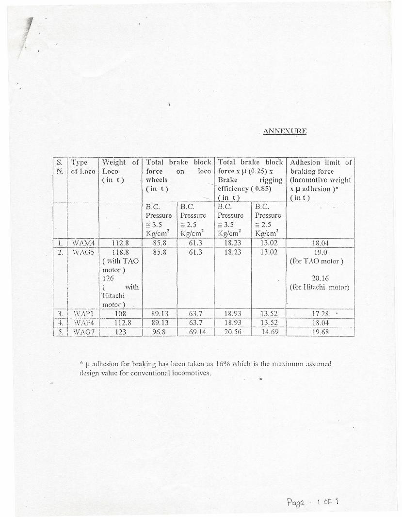
xii) Wheel skidding in locomotive wheels take place whenever braking forcesexerted on the whetts exceeds the limit of adhesion. Adhesion coefficientalong with other factors also depend on track and weather conditions. Incase of poor track conditions clue to bad weather or otherwise, adhesioncoefficient reduces to much lesser extent. In such cases. if the brakes arenot applied judiciously ( lesser brake force with cautious use of PVEF )then wheel skidding of the locomotive wheels may take place. Similarly,total brake block force applied on the wheel tread depends on theprogressive coefficient of friction between brake block and wheel tread.Both ulstmtaneouscoefficicnt of friction as well as progressivecoefficient of friction are dependent on speed i.e higher the speed the

I
/
lower will be the values of both the above types of friction coefficients.These values further keep on increasing with reduction in speed. Thetheoretical values calculated for total brake block force on the wheels'treads with .\9 as well as SA9 in fully applied condition have been givenin Annexure enclosed herewith for a moderate value of coefficient offriction assumed as 0.25 ( prevalent at a speed of around 20-25 kmph ).It may be noted from Annexure-I that with full automatic brakes applied(brake cylinder pressure == 2.5 kg/ern' ) there are very little chances ofexceeding the braking adhesion limit. However, if braking is done withSA9 in fullyrpplicd condition (brake cylinder pressure == 3.5 kg/em' ) thenthere are cha .ces that braking adhesion limit may get exceeded. However,at higher speeds, coefficient of friction will be much lessand there will notbe any chances of wheel skidding even if full independent brakes arcapplied using SA9.
. ,
Therefore, it is clear that braking technique while working a train or lightengine his to be commensurate with speed, weather conditions, trackconditions as well as type of brake blocks.
xiii) Additional C2 relay valve ( A31) should be checked for existence of 6 mmchoke on its exhaust port. If this choke is not existing then it should beinvariably provided.
xiv) The modification of the control circuit as suggested by RDSO videmodification sheet no. WAG5/21 for isolating the proportionate brakes onlocomotive in case of dynamic braking must be ensured.
I
xv) .Drivers/Operating Staff should be encouraged to report the cases of wheelskidding at the first instant and competent staff should be entrusted the jobof investigation wherever possible.
xvi) In case of locomotive's wheel skidding, load should also be checked forjamming.
xvii) RDSO's modification sheet no. ELRSIMS/030412000, Rev. '0' elated6/9.2.2001 on replacement of existing ~" pipe line connecting w1R3reservoir through air flow measuring valve to port no. 1 of additional C::relay valve and port no. ,.3 of additional C2 relay valve to B.P. pipe linewith ~" pipe line should be implemented on priority in all thelocomotives as it will reduce the release time of the load brakesconsiderably.
xviii) .'\.-9 Auto brake valve should be set to regulate the brake pipe pressure of5.0 ± .1 kg/ern' in the release position of the brake valve.
Fb~Q 7 or- 8
xix) HS--~ control valve should be correctly set to regulate the control airpressure from 1.4 to 1.7 kg/em! to get a vacuum in train pipe with 5110"dia leak hole of 530 + 10 mm Hg.
-0xx) The pressure/vacuum gauges should be periodically calibrated to give
correct indication of pressure/vacuum.
xxi) All the pipe joints leading [rom the brake cylinder to the pressure gaugesshould be air tight. Even minor leakage in these joints can causeappreciable drop in reading of the pressure gauge.
6, Drawing/Sketch : None
!11. Agcncy for Implementation:
All Elect.ric Loco Sheds and Workshops of Indian Railways.
8. Distribution:
As per standard mailing list no. List No.ElJIvL'0028, Ver. '0' .
Encl: As above
. ,~I~~=_-( O.ft.P,mdc;) .
for Director Geucral/Elect.F fu\. No : 0522-1:50:374
e-rnail : ~bo;_~@l.(I~:>':;Jj!D~Lg.QLi!JCopy to:
FIN
Encl: As above
{;]I .'4fJ~-,-Y~-r _.. ._. _
( O.H..i:·'andc ) -for Director General/Elect.
FAX No: O~22-45G374
S. ITI••..: jn. I (I
1
IIj
I-----t--j II iI Ij Ir-,-' -:-
r'lJ \') I.•.. ! \I i. Ii Ii .I I, j13.)--'1----· -L·1 ! \-r-, I---t--- ..L_5. L_\
. ANNEXlJRE
-~~--.I Weight
-ype of Total brake block Total brake block Adhesion limit 0
f Loco Loco force on loco force x}..l (0.25) x braking force(in t) wheels Brake rigging (locomotive weight
(in t)-efficiency ( 0.85) x \-l adhesion )"
'- - (in t ) ( in t)--
B.C. B.C. B.C. B.C. ..
Pressure Pressure Pressure Pressure~ 3_5 ~ 2.5 ~ 3.5 ~ 2.5
----' Kg/ern' Kglcm2 Kg/ern' Kg/ern'VAM4 112.8 85.8 6l.3 18.23 13.02 18.04\,l ,·,er s -I 118-8 85.8 61.3 18.23 13.02 19.0
(with TAO (for T AO motor)j motor )I 116 20.16I ( with I (for IIitachi motor)I lIit,;chi! motor) -
Ir----·-·T---- . j·'vAIT) 1 108 89.13 63.7 18.93 13.52 17.28
,'/ij)-4--T- 112.8 I ---- -89.13 63.7 18.93 13.52 18.04
VAG7 'r--i23 196.8------ - ..
69.14 1 20.56 I 14.69 I 19.68________L _____._____ --_ ..•_--
>~ I-l adhesion for braking has been taken as 16~'b which is the maximum JSSllmCO
design value for conventional locomotives._'J>
Related Documents


