Natural Screen Tester Reference Guide Version 1.5 October 2019

Welcome message from author
This document is posted to help you gain knowledge. Please leave a comment to let me know what you think about it! Share it to your friends and learn new things together.
Transcript

Natural Screen Tester
Reference Guide
Version 1.5
October 2019

This document applies to Natural Screen Tester Version 1.5 and all subsequent releases.
Specifications contained herein are subject to change and these changes will be reported in subsequent release notes or new editions.
Copyright © 2017-2019 Software AG, Darmstadt, Germany and/or Software AG USA, Inc., Reston, VA, USA, and/or its subsidiariesand/or its affiliates and/or their licensors.
The name Software AG and all Software AG product names are either trademarks or registered trademarks of Software AG and/orSoftware AGUSA, Inc. and/or its subsidiaries and/or its affiliates and/or their licensors. Other company and product namesmentionedherein may be trademarks of their respective owners.
Detailed information on trademarks and patents owned by Software AG and/or its subsidiaries is located athttp://softwareag.com/licenses.
Use of this software is subject to adherence to Software AG's licensing conditions and terms. These terms are part of the productdocumentation, located at http://softwareag.com/licenses/ and/or in the root installation directory of the licensed product(s).
This software may include portions of third-party products. For third-party copyright notices, license terms, additional rights or re-strictions, please refer to "License Texts, Copyright Notices and Disclaimers of Third-Party Products". For certain specific third-partylicense restrictions, please refer to section E of the Legal Notices available under "License Terms andConditions for Use of Software AGProducts / Copyright and Trademark Notices of Software AG Products". These documents are part of the product documentation,located at http://softwareag.com/licenses and/or in the root installation directory of the licensed product(s).
Use, reproduction, transfer, publication or disclosure is prohibited except as specifically provided for in your License Agreement withSoftware AG.
Document ID: NSR-REFGUIDE-15-20191014

Table of Contents
1 About this Documentation .............................................................................................. 1Document Conventions ............................................................................................. 2Online Information and Support ............................................................................... 2Data Protection ........................................................................................................... 3
2 Natural Screen Tester Eclipse Preferences ...................................................................... 53 Test Project Configuration Parameters ............................................................................ 7
General Test Project Parameters ................................................................................. 8Host Parameters ......................................................................................................... 9Keyboard Mappings ................................................................................................. 14Language .................................................................................................................. 14Navigation ................................................................................................................ 15Screen Content ......................................................................................................... 15Windows .................................................................................................................. 16
4 Host Configuration Parameters ..................................................................................... 19Host Configuration: Connectivity ............................................................................ 20RPC ........................................................................................................................... 21Security ..................................................................................................................... 22
5 Session Properties and Toolbars .................................................................................... 23Display Session Properties ....................................................................................... 24Session View Main Toolbar ...................................................................................... 28Test Case Procedure Toolbar .................................................................................... 28Test Project Toolbar .................................................................................................. 29Navigation Toolbar .................................................................................................. 29
6 Screens and Screen Groups ........................................................................................... 317 Procedures ..................................................................................................................... 33
Procedure Input and Output Attribute Types ......................................................... 34Flow Procedure Editor ............................................................................................. 35Test Case Procedure Editor ...................................................................................... 37Web Procedures ........................................................................................................ 38General Nodes .......................................................................................................... 42Flow Procedure Nodes ............................................................................................. 48Test Case Procedure Nodes ...................................................................................... 52Web Procedure Nodes .............................................................................................. 56General Expressions ................................................................................................. 58Test Case Specific Expressions ................................................................................. 68Web Procedure Specific Expressions ....................................................................... 77Program Procedures ................................................................................................. 78
8 Connection Pools ........................................................................................................... 81General ..................................................................................................................... 82Pool ........................................................................................................................... 82Keep-alive ................................................................................................................. 83Connection Information Sets .................................................................................... 83Pool Size Control Policy Considerations .................................................................. 84
iii
Navigation ................................................................................................................ 859 Connection Information Sets ......................................................................................... 8710 Natural Screen Tester Log Files ................................................................................... 89
Server Log ................................................................................................................ 90Connection Pool Log ................................................................................................ 90Logging a Message from within a Procedure .......................................................... 91Test Case Procedure Failure Log .............................................................................. 91GCT Trace File .......................................................................................................... 91
11 Database Entity ............................................................................................................ 9312 Troubleshooting ........................................................................................................... 95
Test Project Map ....................................................................................................... 96Connection Pools ...................................................................................................... 96Natural for UNIX APX Component ......................................................................... 98Web Procedures ........................................................................................................ 99Error Messages ....................................................................................................... 100
13 List of Appendices ..................................................................................................... 10314 Appendix A: Reserved Words in Natural Screen Tester ........................................... 10515 Appendix B: Security in Natural Screen Tester ......................................................... 111
End-To-End Security .............................................................................................. 112Host <> Natural Screen Tester Server ..................................................................... 112Development Time ................................................................................................. 112Connection Pools .................................................................................................... 113Running Natural Screen Tester Server with a Java Policy File .............................. 113
16 Appendix C: Natural for UNIX Installation .............................................................. 115Installing APX Component for Natural UNIX Protocol ........................................ 116Installing Natural for Natural Screen Tester on OpenVMS Hosts ......................... 123Closing the Natural Application and Natural in Error Situations ......................... 127Restrictions ............................................................................................................. 128
17 Appendix E: SSL Cipher Suites Supported by Natural Screen Tester ....................... 13118 Appendix F: Syntax and Format Reference ............................................................... 135
Regular Expression Syntax ..................................................................................... 13619 Appendix G: ASCII Character Table .......................................................................... 13920 Appendix H: SDFX File Format Definition ............................................................... 143
Introduction ............................................................................................................ 144Mapset File Structure ............................................................................................. 144Defining Maps ........................................................................................................ 145Defining Identifiers ................................................................................................ 146Defining Fields ....................................................................................................... 148Defining Map Steps ................................................................................................ 152Example of an SDFX File ........................................................................................ 154
21 Appendix I: Dynamic Field Mapping Limitations .................................................... 15722 Appendix K: Host Supported Code Pages ................................................................ 159
Reference Guideiv
Reference Guide

1 About this Documentation
■ Document Conventions ...................................................................................................................... 2■ Online Information and Support ........................................................................................................... 2■ Data Protection ................................................................................................................................. 3
1

Document Conventions
DescriptionConvention
Identifies elements on a screen.Bold
Identifies service names and locations in the format folder.subfolder.service,APIs, Java classes, methods, properties.
Monospace font
Identifies:Italic
Variables for which you must supply values specific to your own situation orenvironment.New terms the first time they occur in the text.References to other documentation sources.
Identifies:Monospace font
Text you must type in.Messages displayed by the system.Program code.
Indicates a set of choices from which you must choose one. Type only the informationinside the curly braces. Do not type the { } symbols.
{ }
Separates two mutually exclusive choices in a syntax line. Type one of these choices.Do not type the | symbol.
|
Indicates one or more options. Type only the information inside the square brackets.Do not type the [ ] symbols.
[ ]
Indicates that you can type multiple options of the same type. Type only theinformation. Do not type the ellipsis (...).
...
Online Information and Support
Software AG Documentation Website
You can find documentation on the Software AG Documentation website at http://documenta-tion.softwareag.com. The site requires credentials for SoftwareAG's Product Support site Empower.If you do not have Empower credentials, you must use the TECHcommunity website.
Software AG Empower Product Support Website
If you do not yet have an account for Empower, send an email to [email protected] name, company, and company email address and request an account.
Once you have an account, you can open Support Incidents online via the eService section ofEmpower at https://empower.softwareag.com/.
Reference Guide2
About this Documentation
You can find product information on the Software AG Empower Product Support website at ht-tps://empower.softwareag.com.
To submit feature/enhancement requests, get information about product availability, and downloadproducts, go to Products.
To get information about fixes and to read early warnings, technical papers, and knowledge basearticles, go to the Knowledge Center.
If you have any questions, you can find a local or toll-free number for your country in our GlobalSupport Contact Directory at https://empower.softwareag.com/public_directory.asp and give usa call.
Software AG TECHcommunity
You can finddocumentation and other technical information on the SoftwareAGTECHcommunitywebsite at http://techcommunity.softwareag.com. You can:
■ Access product documentation, if you have TECHcommunity credentials. If you do not, youwill need to register and specify "Documentation" as an area of interest.
■ Access articles, code samples, demos, and tutorials.■ Use the online discussion forums, moderated by Software AG professionals, to ask questions,discuss best practices, and learn how other customers are using Software AG technology.
■ Link to external websites that discuss open standards and web technology.
Data Protection
SoftwareAGproducts provide functionalitywith respect to processing of personal data accordingto the EU General Data Protection Regulation (GDPR). Where applicable, appropriate steps aredocumented in the respective administration documentation.
3Reference Guide
About this Documentation

4

2 Natural Screen Tester Eclipse Preferences
The Natural Screen Tester Eclipse preferences can be accessed via theWindows > Preferencesmenu in the Software AG node.
Remember passwordsRemembers the server passwords.When this check box is not selected the login pop-up is alwaysdisplayed.
Always use the highest prioritized ScreenGroup (when creating Screens using ScreenCreationDefinitions)
When creating screens based on screen creation definitions which are defined within screengroups, you can determine to always use the highest prioritized screen group and not to askthe user every time which screen group to use. When this check box is not selected the dialogbox requesting you to select the relevant screen group will always be displayed.
Switch to Natural Screen Tester perspective upon Natural Screen Tester wizards completionWhen in an Eclipse perspective which is not the Natural Screen Tester perspective, and yourun a wizard, once the wizard is completed, the perspective will change to be the NaturalScreen Tester perspective.
Show Test Project Map on startupDetermines whether the Test Project view is displayed when opening a test project. By defaultthe Test Project Map view is displayed.
Natural Screen Tester installation directoryIndicates the directory where Natural Screen Tester is installed.
JDK locationIndicates the directory where JDK is located.
Software AG Tomcat locationIndicates the directory where Software AG Tomcat is located.
5

6

3 Test Project Configuration Parameters
■ General Test Project Parameters .......................................................................................................... 8■ Host Parameters ............................................................................................................................... 9■ Keyboard Mappings ......................................................................................................................... 14■ Language ...................................................................................................................................... 14■ Navigation ..................................................................................................................................... 15■ Screen Content ............................................................................................................................... 15■ Windows ....................................................................................................................................... 16
7

The test project properties dialog box can be accessed by right-clicking on the relevant test projectand selecting Properties. Here you edit the basic properties as well as advanced properties:
See alsoHost Configuration Parameters.
General Test Project Parameters
This node is the first node of the test project properties and provides the most basic test projectinformation. Right-click on an test project to access the general properties.
Test project nameA unique name defined when first creating the test project. The test project name is read onlyhere but can be changed by right-clicking on the test project and selecting Rename....
DescriptionA brief description of the test project.
Initialization mode
AutomaticAutomatically loaded when the server is started.
When first accessedLoaded when first accessed, in other words, when the code that initializes startup is firstcalled (default).
Reference Guide8
Test Project Configuration Parameters
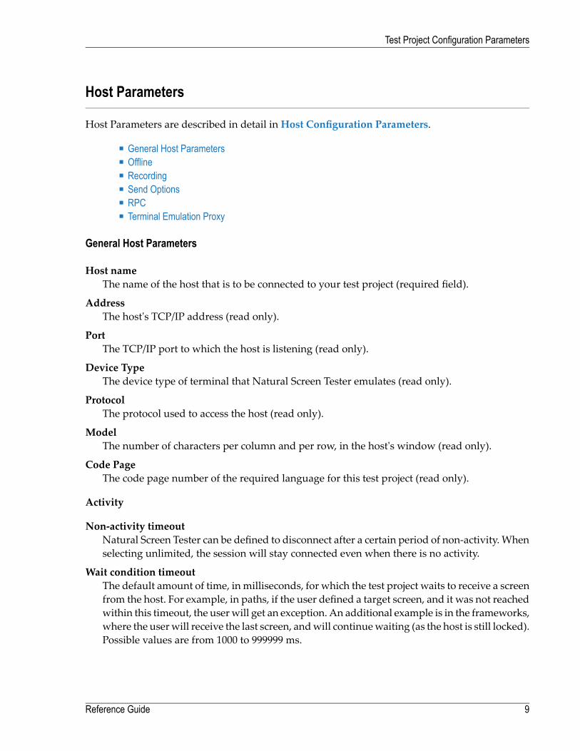
Host Parameters
Host Parameters are described in detail in Host Configuration Parameters.
■ General Host Parameters■ Offline■ Recording■ Send Options■ RPC■ Terminal Emulation Proxy
General Host Parameters
Host nameThe name of the host that is to be connected to your test project (required field).
AddressThe host's TCP/IP address (read only).
PortThe TCP/IP port to which the host is listening (read only).
Device TypeThe device type of terminal that Natural Screen Tester emulates (read only).
ProtocolThe protocol used to access the host (read only).
ModelThe number of characters per column and per row, in the host's window (read only).
Code PageThe code page number of the required language for this test project (read only).
Activity
Non-activity timeoutNatural Screen Tester can be defined to disconnect after a certain period of non-activity. Whenselecting unlimited, the session will stay connected even when there is no activity.
Wait condition timeoutThe default amount of time, in milliseconds, for which the test project waits to receive a screenfrom the host. For example, in paths, if the user defined a target screen, and it was not reachedwithin this timeout, the userwill get an exception. An additional example is in the frameworks,where the userwill receive the last screen, andwill continuewaiting (as the host is still locked).Possible values are from 1000 to 999999 ms.
9Reference Guide
Test Project Configuration Parameters

FlickerAn amount of time, defined in milliseconds, in which the test project waits for the host to sendinformation. This is necessary, as information may be sent in a few chunks of data, before de-claring that it has received the entire screen. This is a value defined for all the test projectscreens, and can be bypassed using the Wait Conditions. (By default, this value is set to 0).Possible values are from 0 to 10000 ms. Refer to Handling Flickering of Host Screens.
Blank screen timeoutThe amount of time, defined in milliseconds, in which the test project waits after receiving ablank screen, giving the host the opportunity to continue sending the next screen before return-ing to the client. This is very similar to the flicker parameter, the difference being that theflicker featurewaits the complete amount of time defined as oppose to the blank screen timeoutwhich finishes once the screen stops being blank. In addition, this setting only applies to blankscreens, and in this way, does not slowdown the performance of the entire test project. (Defaultvalue: 500 ms). Possible values are from 0 to 10000 ms.
Offline
Work offlineIndicates whether to simulate a communication with the host by using a pre-recorded file. Bydefault, this feature is not enabled.
Files on serverLists the trace files which are on the server. Click and browse to copy a file from your localmachine to the server.
Simulate host delayAllows a session replayed by aGCT to simulate the host's communication delay or to predefinea time delay to wait before showing the information (this is because generally, the test projectis faster when replayed). Available values: No delay, Simulate host, 500- 10000 ms (by defaultNo delay is selected).
Recording
TheRecord Trace File feature enables creating a file, whichwill trace the connection communication(connection pool or user) between theNatural Screen Tester server and the host, for each connection.It is possible to define whether a single trace file will be created, replacing the previously savedfile or if the data will be saved to a new file for every new connection or session. Identifying theseparately saved files is possible by inserting identifying parameters in the file name (the sessionID, connection time and/or connection ID).
Record display sessions (trace files)Select this option to enable recording trace files.
Compress (create files in zip format)Select this option to compress the file.
Reference Guide10
Test Project Configuration Parameters

Encrypt (using server private key)Select this option to encypt the file. In order to encrypt files, youmust first define the encryptionkey (In the Server properties, General tab).
Suppress hidden fieldsConceals passwords and hidden fields in the trace file.
Note: The "Suppress hidden fields" option is not supported when recording using Ter-minal Emulation Proxy.
File nameThe name of the trace file. You can create a separate File for each session, or connection andthe name can include the session ID, creation time and/or connection ID.
%u will insert the session ID.
%t will insert the time stamp of the connection.
%c will insert the connection ID.
Location of folderBrowse and select the location of the folder where the files will be stored. Determine whethersub folders will be created for each year/month/day.
Open recordings folderOpens the Windows Explorer and displays the location and list of existing trace files.
Send Options
The Send Options enable to configure how and whether a field is sent to the host when there aremismatches between the field and the host field.
Throw exception when field content does not match host field attributesWhen the field does not match the host field attributes, for example, when the value to beentered is longer than the field length, or the field is not found, or the cursor position is not inan unprotected field, an error will occur.
When field content is longer than host field length...When the field content is longer than the host field it is possible to select the option that thisfield will not be sent to the host, or that the contents of the field will be cut to match the hostfield size.
11Reference Guide
Test Project Configuration Parameters

RPC
Available in test projects associated with AS/400 only.
In the RPC tab, connection parameters for theNatural Screen Tester ProgramCalls. This is enabledonly for AS/400 hosts.
Enable connection poolSelecting this check box indicates that the server should maintain a pool of connections.
Number of connections in poolThe minimum and maximum number of connections it is possible to have in the pool at onegiven time.
Minimum available connectionsThe minimal number of connections in the pool that are ready to serve a transaction. If thenumber of available connections in the pool falls below this number, new connections will becreated until the minimum is reached.
Connections created when pool is increasedThe number of connections created each time the pool size is increased.
Number of attempts to obtain a connectionThe number of attempts to create a connection.
Delay between unsuccessful attemptsThe time, in milliseconds, before retrying to obtain a connection.
Wait for available connection timeoutIf no connections are available in the connection pool, the length of time towait for an availableconnection before a timeout message is sent.
Connection timeoutThe total time, in minutes, that a connection can exist. Setting the value to "Unlimited" sets notimeout. After the set time elapses the connection is terminated.
Disconnect after usageThis checkbox determines whether to restart the connection once a user finishes using a con-nection or to terminate the connection when it is returned to the pool. When checked, theconnection is terminated after usage.
Reference Guide12
Test Project Configuration Parameters

Terminal Emulation Proxy
This feature enables redirecting emulation network traffic to pass through the port configured inthis screen (only relevant for AS/400 and Mainframe hosts).
Use Terminal Emulation ProxySelect this check box to use the Terminal Emulation Proxy option.
Note: When recording using Terminal Emulation Proxy, the "Suppress hidden fields"option is not supported.
Terminal Emulation Proxy portEnter the port number throughwhich youwould like to redirect the emulation network traffic.
13Reference Guide
Test Project Configuration Parameters

Keyboard Mappings
Use the Keyboard Mappings node to map host keys to keyboard keys.
Keyboard key/sThe combination of keyboard keys such as Shift+W. The values in this field are entered intothe field as they are pressed on the keyboard.
Note: When using the keyboard keys within the web test project, the CTRL+N andCTRL+K keys are blocked by default as they cause multiple browser windows to usethe same session (this can be manually set in the config/gx_keyboardMappings.xmlfile).
CommandDetermines the host key that will be sent. The host key should be in square brackets and canbe selected from the standard host keys list to the right of the Host key field.
Language
The Language node enables you to define the language used in the test project as well as directionsettings, relevant mainly for right-to-left languages.
LanguageThe test project's language.
The following settings are relevant for right-to-left languages. The option you select is the defaultsetting for all the screens, but can be changed for a specific screen in the relevant screen identific-ation properties.
Screen directionRelevant for mainframe hosts only. The screen direction of right-to-left languages differs ac-cording to the original host settings, andwhen incorrectly set, can cause the screen to be illegible.In order to correct this, define the suitable screen direction.
Typing directionRight-to-left languages may display typed-in text in the client test project text fields, alignedto the left of the field. In order to display the text aligned to the right, select the right-to-leftoption. Numeric type fields typing direction will always be left-to-right.
Tab directionWhen pressing the Tab button the cursor moves to the next consecutive field. The directionthe cursor moves (moving to the next field to the left or moving to the next field to the right)must be correctly defined in order to preserve the screen logic.
Reference Guide14
Test Project Configuration Parameters

Navigation
Enable map steps recording while navigating in sessionOnce selected, the test project map will record the navigation steps between the screens.
Exception pathAnException path is initiated once a test case procedure that is being executed reaches a screenthat is not defined as the To Screen of the step that was executed or as the From Screen of thenext step to be executed. When such a screen is reached, Natural Screen Tester immediatelysearches (ignoring the wait condition timeout) for the Exception Path that has been defined.If an Exception path is found, it is executed. Natural Screen Tester will then try to continuethe original path from the point before the Exception Path was initiated. The attempt to findand execute a suitable Exception path will be repeated as many as 30 times, after which theoriginal path will fail to be executed.
Screen Content
Replace padding characters with spaceSome hosts fill input fields with a character such as underscores or dots (following the actualcontent of the field). You may define that Natural Screen Tester replaces this character in theinput field with spaces when the server sends the field's contents to the client. It is possible todefine up to two padding characters.
The radio buttons enable applying this to all fields or only to input (unprotected) fields (inputfields also include test project fields with "both" protection type - protected and unprotected).
Remove from both sides of textThis field determines whether the padding character will be removed from both sides ofthe field or just from one side (in LTR test projects the character will be removed from theright side, and in RTL test projects the character will be removed from the left side). Innumeric type input fields, the characters are removed from both sides of the content (as itis clearly not a number).
Trim FieldsSome hosts fill input fields with spaces (following the actual content of the field). You mayinstruct Natural Screen Tester to remove the spaces from the content of the input field.
The radio buttons enable applying this to all fields or only to input (unprotected) fields or inputfields and test project fields with "both" protection type - protected and unprotected).
Remove from both sides of textThis field determines whether the spaces will be removed from both sides of the field orjust from one side (in LTR test projects the character will be removed from the right side,and in RTL test projects the character will be removed from the left side). In numeric type
15Reference Guide
Test Project Configuration Parameters

input fields, the characters are removed from both sides of the content (as it is clearly nota number).
Return Content of Hidden FieldsSome hosts have hidden fields in the screen. Usually these fields' visibility depends on thecontext of the screen. By default, Natural Screen Tester does not return the content of thesefields because the user in an emulator cannot see them. However, sometimes their content canbe important and one may want to access it (for example, hidden fields can be used as screenidentifiers, or as a part of a test case procedure's logic). Check the Return content of hiddenfields check box to return the content of all hidden fields in the test project.
Split fields when an attribute changes (color, blinking etc.)This field determines whether when an attribute changes in the middle of a field, this fieldwill be split.
Windows
In the Designer, you can describe the way a window is displayed in the host. The Window defin-itions are used to correctly identify screens and to open hostwindows as separate pop-upwindows.Click the Add orDelete button to make any changes.
Note: When the host is aNatural UNIX host, this tab is disabled, as thewindows' definitionsare included in the Natural-Unix protocol and do not require being defined via NaturalScreen Tester.
List of host windowsThe list of hostwindows is displayed here. Add or removewindows by clicking on the relevantbutton.When adding awindow you are required to select the type ofmodal windows the hostsends. There are two types: Reversed Video or Frame. For test projects that have more thanone level ofwindows (awindowwithin awindow),where each level is definedwith a differentWindow Type, be sure to define the windows in the correct order.
Attributes
Frame is intensifiedOne of the parameters that assist in recognizing windows. This parameter determineswhether the frame will be recognized as a window when the frame is intensified.
Frame with titleOne of the parameters that assist in recognizing windows. This parameter determineswhether the frame will be recognized as a window if the frame has a title.
Identify window even though unprotected fields exist outside window areaThis field determineswhether or not an area that seemingly could be identified as awindowwill be recognized as one, even though there are unprotected fields outside the windowarea.Note:When awindow is identifiedwithin a screen, andworkingwithmodalwindows,it is not possible to edit unprotected fields outside the window area.
Reference Guide16
Test Project Configuration Parameters

Content
Remove window frameCharacters appear on the first line of the screenwithout thewindow frame. Suitable typicallyfor Natural mapping test projects.
Display window titleDisplays the window title in the window frame to be viewed.
Frame characters
VerticalThe character used for the host's modal window vertical lines. The character can be eithertyped in, or selected from the list of characters.
HorizontalThe character used for the host's modal window horizontal lines. The character can beeither typed in, or selected from the list of characters.
CornersThe character used for the host's modal window corners. The character can be either typedin, or selected from the list of characters.
Synchronize cornersDefines that all four corners of the window frame are the same character (default). Whenselecting this option, define the character for each of the corners (upper-left, lower-left,upper-right and lower-right).
17Reference Guide
Test Project Configuration Parameters

18

4 Host Configuration Parameters
■ Host Configuration: Connectivity ......................................................................................................... 20■ RPC ............................................................................................................................................. 21■ Security ......................................................................................................................................... 22
19

See also Test Project Configuration Parameters
Host Configuration: Connectivity
Name/IP addressThe host's TCP/IP address (IPv4 and IPv6 address formats are supported).
PortThe TCP/IP port to which the host is listening.
Device typeThe device type of terminal.
ProtocolThe protocol used to access the host.
CommentProtocolDevice Type
TN3270 TN3270EMainframe: IBM-3278, IBM-3279 (onlysupported via SNA servers that convert SNAto TN3270)
Natural-APX,Natural-NSW
Natural-UNIX (Software AG)
9750BS2000
TELNETUNISYS-TD830 (UNISYS T27 EBCDIC),UNISYS-TD830-ASCII (UNISYS T27 ASCII)
Only block mode applicationsare supported in Webenablement.
TN6530TANDEM: TN6530-8
TN6680FUJITSU-6680-00, FUJITSU-6680-02
TN5250 TN5250EAS/400: IBM-3179, IBM-3477-FC, IBM-5555
Supported only by NaturalScreen Tester Servers installedon Win 32 platforms.
TN560HITACHI
ModelThe number of characters per column and per row, in the host's window.
ApplicationThe name of the application on the BS2000, to which you want to connect (relevant only toBS2000). The name can be up to 8 characters long. $DIALOG is provided as the default name.The connection to the hostwill be establishedusing anOpen command,without anyparameters.
Application scriptThe name of the shell script file required to start the Natural application (relevant Natural-UNIX).
Reference Guide20
Host Configuration Parameters

Parameter fileThis file contains the configuration parameters relevant forNatural-UNIX. Enter the parameterfile name as it appears in Natural, without the file extension. For example: SYSTRANS.SAGshould be written as SYSTRANS.
Connection timeoutThe number of milliseconds the application will try to connect to the host, before it announcesfailure.
Code pageThe code page number of the required language for this application.
Convert input to uppercaseSends data to the host as uppercase (overrides default host configuration-backwards compat-ible).
Use 8-bit dataDetermines whether to use an 8-bit ASCII table. When not selected, the 7-bit ASCII table isused by default.
RPC
Note: This tab is not displayed in Mainframe host applications.
UsernameInsert a User ID to log into an AS/400 host.
PasswordA password to log into an AS/400 host.
Library listA list of libraries separated by spaces, in theAS/400 host called by programs thatmay referencethem. If a program calls a library that is not recorded in the Library list, the program may notfunction properly.
Create debug logCheck this check box to save a debug log when running Natural Screen Tester programs.
File nameSpecify the log file.
21Reference Guide
Host Configuration Parameters

Security
Connect using SSHEnables connecting using the SSH connection between the Natural Screen Tester server andthe host.
Use SSL connection to hostEnables using the SSL connection between the Natural Screen Tester server and the host.
Add and Remove iconsThe Add icon enables adding a valid X509 certificate. Use the remove button to remove certi-ficates not used.
Note: This can be used in any block mode host, however this has only been tested on a 3270Mainframe host.
Reference Guide22
Host Configuration Parameters
5 Session Properties and Toolbars
■ Display Session Properties ................................................................................................................ 24■ Session View Main Toolbar ................................................................................................................ 28■ Test Case Procedure Toolbar ............................................................................................................. 28■ Test Project Toolbar ......................................................................................................................... 29■ Navigation Toolbar ........................................................................................................................... 29
23

Display Session Properties
Refer to Creating a Display Session in the Designing and Developing a Test Case documentation.These definitions override the default connection configuration as defined in the test projectproperties.
■ Connectivity Properties
Reference Guide24
Session Properties and Toolbars

■ General Properties
Connectivity Properties
DescriptionA suitable description for the session.
Use test project configurationSelect Use test project configuration to implement the configuration as set in the test projectproperties.
OnlineSelect Online when you want to connect online to the configured host.
25Reference Guide
Session Properties and Toolbars

Offline (using trace files)Indicatewhether to simulate a communicationwith the host by using a pre-recorded file. SelectOffline (using trace files) and then select the replay file from the list displayed in the Files onserver list or browse and select a file from a folder.
Connection PoolSelect Connection Pool and choose one of the test project's Connection Pools.
Reference Guide26
Session Properties and Toolbars

General Properties
Session IDCustom session ID
Session passwordCustom session password.
Use default configurationSelect Use default configuration to implement the Test Project Trace File configuration as setin the test project properties.
Don't create trace fileSelectDon't create trace file if you do not want to create a trace file.
Create a trace fileIndicates whether to log the communication with the host into a file. Select Create a trace fileand insert the trace file name. If you include %u or %t (or both) in the file name, you can createfiles for diverse users with different session ID and time information. Check Session ID if you
27Reference Guide
Session Properties and Toolbars

want to override the files of the same session ID. Check time to add a time stamp to the filename. This does not overwrite previous files. Check Connection ID to add full connection ID(test project, connection pool, connection) to the file name.
Session View Main Toolbar
Show/hide attributes
Show/hide input fields
Window: will gray out or display in regular colors, the screen area outside the window. It is notpossible to navigate outside the window.
Test Case Toolbar
Navigate to Screen Toolbar
Restart Session
Synch with host
Character mode/Block mode
Change screen direction
Update Screen Image
Edit the current screen
Identify new screen/screen group
Automatically identify unprotected screens
Screen creation mode: automatic, semi-automatic or manual
Test Case Procedure Toolbar
The Test Case Procedure toolbar is used to record, run and debug a test case.
Start recording
Stop recording
Mark possible input - marks the input (unprotected) fields of the current screen
Mark possible output - marks the fields that will be used as assertions
Loop
Reference Guide28
Session Properties and Toolbars

Get loop condition text
Run
Debug
Test Project Toolbar
The Test Project toolbar is available to be used when developing a test project. Using the toolbaryou can:
■ Check that the test project definitionswork as expected (by selecting a screen, and checking thatNatural Screen Tester is able to navigate to this screen).
■ Navigate to a specific screen to edit and make changes in the screen.
The Test Project toolbar is not displayed when working offline.
Navigate to screen
Open the entity's editor
Find entity
Navigation Toolbar
Slider, indicates current location in the replay file.
Screen number box, displays the current screen number.
Displays a list of the available screens and screen groups.
Open the entity's editor
Find entity
When clicked, displays the screen number entered in thescreen number box.
Show User Input button displays the user input enteredwhile the replay file was recorded. When the button isclicked, the contents of the input fields that were changedappear in red, a string representation of the host key sentappears in the Toolbar and the cursor is positioned in theposition it was in when the screen was sent to the host.
29Reference Guide
Session Properties and Toolbars

Note: When replaying a file that has a Connection Pool, the Replay Navigator slider is notavailable for the Natural UNIX protocol.
Reference Guide30
Session Properties and Toolbars

6 Screens and Screen Groups
In the Screen Editor edit the screen definitions: the identifiers, fields, screen groups, tables andmap steps. The Screen Editor can be accessed after creating a new screen or by editing an existingone. Refer to Screens in the Designing and Developing a Test Case documentation.
Identifiers TabLists the identifying elements that identify the screen. Refer to Identifiers, Adding or Deletingan Identifier and Editing a Screen Identifier.
Identify entire screen (ignore window definition)Selecting this check box indicates that the application'swindowdefinitions are ignored duringthe identification of this screen. Once the screen is identified, the full screen is used. This checkbox is only enabled when the screen has a window.
Select this check box:■ When the screen includes multiple windows and the window definition in this screen isambiguous.
■ To override general application window identification definitions in a specific screen.
Note: Changing the selection of this field will cause existing position-dependent defini-tions in the screen (such as identifiers and fields) to be incorrect. It is therefore necessaryto redefine identifiers and fields when selecting/clearing the check box. By default thisfield is not selected.
List of IdentifiersLists the existing identifiers. There are several columns in this table:
31

Graphic indication of the type of identifier.Icon
Textual indication of the type of identifierType
Description of the identifier contentsContent
The position within the screenRow
The position within the screenColumn
Screen Fields TabLists the screen'smappings. Enables adding newmappings, such as single,multiple or dynamicmappings. Next to each mapping, an icon indicates whether the mapping is inherited from ascreen group,whether themapping has been defined locally for the current screen, orwhetherthe mapping was originally inherited from a screen group but has been overridden locally tosuit the current screen. When selecting an inherited mapping, it is not possible to change themapping properties. When selecting a local mapping, all properties can be changed. Whenselecting an overridden mapping, all properties can be changed, except for the name.
DescriptionIcon
The mapping has been defined locally for the current screen.
The mapping is inherited from a screen group.
Themapping was originally inherited from a screen group but has been overridden locally to suitthe current screen.
Cancels overriding an inherited mapping.
Icon Legend
TheOverride/CancelOverride hyperlink (enabledwhennot selecting a localmapping) overridesan inheritedmapping, or cancels overriding an inheritedmapping (using the inherited values).
The Add Field Mapping hyperlink enables adding a new field mapping.
The Delete Field Mapping hyperlink (enabled on when selecting a local mapping) removesthe mapping.
Reference Guide32
Screens and Screen Groups

7 Procedures
■ Procedure Input and Output Attribute Types .......................................................................................... 34■ Flow Procedure Editor ...................................................................................................................... 35■ Test Case Procedure Editor ............................................................................................................... 37■ Web Procedures ............................................................................................................................. 38■ General Nodes ............................................................................................................................... 42■ Flow Procedure Nodes ..................................................................................................................... 48■ Test Case Procedure Nodes .............................................................................................................. 52■ Web Procedure Nodes ..................................................................................................................... 56■ General Expressions ........................................................................................................................ 58■ Test Case Specific Expressions .......................................................................................................... 68■ Web Procedure Specific Expressions .................................................................................................. 77■ Program Procedures ........................................................................................................................ 78
33

A Natural Screen Tester procedure is a well-defined encapsulation of a complete process, andcontains process input arguments, process output arguments and the process definition itself. Aprocedure group is a container of several procedures. The following procedure types are available:
■ Test Case ProcedureEncapsulates a process of navigation in host screens, collecting data or submitting data.
■ Flow ProcedureEncapsulates a complex process that can combine host sessions and other data sources: databases,host transactions (RPC), other web services.
■ Web ProcedureEncapsulates a process of navigating and selecting elements in the Web.
■ Program ProcedureEncapsulates a host transaction (in COBOL or RPG), invoked via RPC and not via the screenslayer.
■ External Web ServicesEncapsulates a web service that is external to Natural Screen Tester, invoked via SOAP.
This chapter covers the following topics:
See also Procedures in the Designing and Developing a Test Case documentation.
Procedure Input and Output Attribute Types
■ Text■ Long■ Boolean (True, False)■ Double■ Integer■ Float■ Byte■ Date: The format can be either 2001-07-04 12:08:56.235 or 2001-07-04T12:08:56.235 (this formatshould be used for Web Services only), or dd/MM/yyyy
See also Defining Procedure Inputs and Outputs in the Designing and Developing a Test Case docu-mentation.
Reference Guide34
Procedures

Flow Procedure Editor
Show nameIncludes the name of the node in the procedure details.
Show detailsIncludes details of the node in the procedure details.
Show descriptionIncludes a description of the node in the procedure details.
The procedure nodes are listed on the right, and can be placed within the procedure by draggingand dropping them to the relevant place within the procedure process. Clicking on one of thetitles, such as Navigation, will display all the available nodes within navigation.
35Reference Guide
Procedures

In the Procedure tree, right-clicking on a node will display the actions available for that node.These may include actions such as expanding or collapsing the node. The root node includessaving an image of the procedure to a file.
Reference Guide36
Procedures

Test Case Procedure Editor
Test Case Procedure Panel
Show nameIncludes the name of the node in the procedure details.
Show detailsIncludes details of the node in the procedure details.
Show descriptionIncludes a description of the node in the procedure details.
The procedure nodes are listed on the right, and can be placed within the procedure by draggingand dropping them to the relevant place within the procedure process. Clicking on one of thetitles, such as Navigation, will display all the available nodes within navigation.
In the Procedure tree, right-clicking on a node will display the actions available for that node.These may include actions such as expanding or collapsing the node. The root node includessaving an image of the procedure to a file.
37Reference Guide
Procedures

Web Procedures
Web Procedure Panel
Show nameIncludes the name of the node in the procedure details.
Show detailsIncludes details of the node in the procedure details.
Show descriptionIncludes a description of the node in the procedure details.
The procedure nodes are listed on the right, and can be placed within the procedure by draggingand dropping them to the relevant place within the procedure process. Clicking on one of thetitles, such as Navigation, will display all the available nodes within navigation.
In the Procedure tree, right-clicking on a node will display the actions available for that node.These may include actions such as expanding or collapsing the node. The root node includessaving an image of the procedure to a file.
Reference Guide38
Procedures

Configuring the Proxy Settings
When your network requires defining a proxy, set the proxy Hostname, Port, Username andPassword in the WebProcedureConfig section in the <Natural Screen Tester installation>/config/gxcon-fig.xml file:
<MainConfiguration>...<ServerConfiguration>...
<webProcedureConfig><proxyHostname></proxyHostname><proxyPort></proxyPort><proxyUsername></proxyUsername><proxyPassword></proxyPassword>
</webProcedureConfig></ServerConfiguration>
</MainConfiguration>
What is an XPath?
Natural Screen Tester deciphers theWeb page and finds elements using standardW3C technologycalled XPath. XPath, the XML Path Language, is a query language for selecting elements from anXMLdocument. XPathwas defined by theWorldWideWebConsortium (W3C) and further detailscan be found at their site. When recording theWeb procedure, and capturing an element, NaturalScreen Tester finds the most suitable XPath that will locate the element in runtime. The XPathtechnology provides flexibility to locate a specific element using various XPaths. The format of anXPath can vary, for example, it can be of a format which only looks for a specific HTML attributesuch as a name or ID within the Web page (recommended) or it can be a canonical XPath whichprovides the whole path, detailing the hierarchy of the tags which point to the element. If there isno name or ID, or if the name/ID is not generic enough, (i.e. if it is specific to a value that is likelyto change in different instances of the page), alternative XPaths should be considered. The altern-ative suggestions by Natural Screen Tester are options which include various levels of hierarchy.The objective is to use an XPath which is based on a "solid" name/ID, with as few as possible levelsof hierarchy as the fewer levels of hierarchy, the more stable the XPath is.
Handling Inline Frames
The suggested XPath has an additional level, andwhen there are inline frames, the XPath combinesthe web page and iframe's XPath into one XPath, to simplify the use within Natural Screen Tester.
For example:
The Web pages standard XPath (refers to the first iframe tag in the main document):/html/body/iframe[1].
The IFrames standard XPath (refers to the second input tag under the first div tag, inside theiframe's document): /html/body/div[1]/input[2].
39Reference Guide
Procedures

The combined XPath used by Natural Screen Tester:/html/body/iframe[1]/html/body/div[1]/input[2].
Troubleshooting
What to do when the Web Procedure fails to run?
The Web Procedure can fail to run for a number of reasons such as an element cannot be foundon the page or unexpected behavior when running JavaScripts. Some of these issues can be solvedby adjusting parameters in the <NSR-installation>/config/gxconfig.xml file. Following is a list ofpossible problems with a recommendation as to what to do and when relevant, which parameterto configure. Below is a snipet of the code as it appears within the gxconfig.xml file.
Timeout error:When running theWeb Procedure, sometimes an errormessage is displayed indic-ating that a timeout occurred, and that the procedure failed and did not run successfully. This canbe for a number of reasons:
■ A specific element used in the procedure was not found on the page. In this case, you shouldtry the following:
1. The XPath defined may not capture the correct element. Run the procedure from within theDesigner and follow the output in the Console area.
2. Refine the XPath to make it more robust. Refer toWhat is an XPath?
3. Change the server log level to "trace" to help you understand where the problem may lie.
4. If you know that this element is on the page, you should try to change the waitElementTimeoutparameter and see if after extending this time the element is found.
■ Required resources are not loaded on the pagewithin a certain amount of time. You can confirmthat this is your problem by setting the log level to "trace" and see that the actions/web elementcontent retrieval is performed on the previous page. Change the navigationTimeout parameterto try and solve this.
Unexpected behavior when running JavaScript methods: If in a scenario which relies on the ex-ecution of a JavaScript method, the results are not as expected. Changing the javascriptTimeoutmay solve this.
CSS related problem:When there is a scenario that relies on the evaluation of CSS rules, and theresults are not as expected, setting the cssEnabled parameter to enabled may solve this.
Reference Guide40
Procedures

<MainConfiguration>...<ServerConfiguration>...
<webProcedureConfig><waitElementTimeout>30000</waitElementTimeout><navigationTimeout>90000</navigationTimeout><javascriptTimeout>30000</javascriptTimeout><cssEnabled>false</cssEnabled>
</webProcedureConfig></ServerConfiguration>
</MainConfiguration>
41Reference Guide
Procedures

General Nodes
Flow, Test Case and Web procedures may consist of a number of nodes. These nodes are definedby the user to perform logical operations and are arranged in the order that these operations areto be executed. Tree nodes have nested scopes,much like blocks in programming languages. Objectsand values are available for mapping in the node in which they are defined and their child nodes,but not in the parent nodes.
The information in this section applies to flow, test case and web procedures and covers the fol-lowing topics:
■ Execute Procedure Node■ New Object Node■ Create Mappings Node■ Merge Arrays Node■ Throw Exception Node■ Log Message Node■ Send Mail Node■ Loop While Node■ For Each Node■ Test If Node■ Switch Node■ Try/Catch Node■ Exit Node■ Sleep Node
See separate sections for Flow Procedure | Test Case Procedure |Web Procedure nodes.
Execute Procedure Node
Used in procedures to execute a procedure and return the procedure's output. It contains aMapperand defines Procedure Input, information about the session (for Test Case procedures and Programprocedures) and Connection Properties (Program Procedures).
To Create an Execute Procedure Node
1 In the Procedure editor, drag and drop the Execute Procedure node (from within the Navig-ation divider) to the relevant position within the procedure.
2 In the bottom half of the screen, select the procedure.
3 Map necessary inputs from the source to the target. The target includes inputs, informationabout the session (for Test Case procedures and Program procedures) and Connection Prop-erties (Program Procedures) such as user ID and password).
Reference Guide42
Procedures

4 After the node is executed, the ProcedureOutput element, depending on the selectedProcedureOutput definition, is available at the procedure scope.
New Object Node
In the New Object node define temporary data structure which can be used within the context.Using the mapping tool, you can map values to parameters within the node, and later use themapper to access the values of these parameters in other nodes within the context.
To create a New Object node
1 In the Procedure editor, drag and drop the New Object node (from within the Assignmentdivider) to the relevant position within the procedure.
2 The object can be defined as simple attribute, array, simple structure or array of structures.Click Add attribute or Add Structure as required. Enter a name and determine whether it isan array. It is also possible to provide a default value.
Create Mappings Node
This node enables you to create mappings between scope objects/variables or expression valuesto any output or object defined in the flow procedure's scope. Refer to using the mapper.
Merge Arrays Node
The Merge Array node is used to create an array of structured elements (objects) from a numberof arrays of simple elements of the same size (such as inputs, or outputs from another procedureetc.). The iteration runs on one of the simple elements and therefore if the size of the arrays of allthe simple elements is not the same, the results of the procedure may be lacking.
The following example will guide you through a basic example of the use of the Merge Arraysnode in flow procedures. The source data is taken from three string array inputs (Name, Age andAddress). The data received as a result of running the procedure will be placed in an array of astructure (in this case, a Business Entity (named Person), which includes Name, Age and Addressattributes).
1. Create a Data Structure entity. In the Name field type Person and save the entity.
2. Open the entity in the Editor and add three attributes: Name, Age andAddress (refer to BusinessEntity and Creating Business Entity Attributes). Save the Data Structure.
3. Create a flow procedure and add three array inputs: Name, Age and Address to the Flow Pro-cedure node (refer toDefining Inputs andOutputs). Add an output called People. In thisOutput,add a structure. In the Type field select the data structure Person and select the Array checkbox.
4. In the Procedure editor, drag and drop the Merge Arrays node (from within the Assignmentdivider) to the relevant position within the procedure.
43Reference Guide
Procedures

5. Click Select to select the object, where the data received as a result of running the procedurewill be placed. The Modify Expression dialog box is displayed.
6. Double-click People to determine that the data will be mapped to the output called People.Click OK.
7. Click For Each Select Object to determine the input array that the procedure will run over. TheModify Expression dialog box is displayed.
8. Double-click In\Name to determine that the procedure will run over the array of names. ClickOK.
9. In the bottom panel, expand In to view the list of inputs.
10. Click and drag In\Name to People\Name, creating a line between the two. In the same way,create a line between In\Age to Person\Age and between In\Address to Person\Address.When the procedure is run, an array of structures will be created (People).
11. Click Condition to filter some of the mappings. For example, to avoid mapping values fromempty entities of the source arrays.
12. Click the Play icon in the debugger toolbar to test the procedure. Enter values for the inputstrings for three names, ages and addresses.
13. Click OK. The bottom panel displays the procedure inputs, outputs and status. The In nodedisplays the string array data entered in the Get Flow Input dialog. The Out node displaysstructures of the Business Entity Person, which consists of the name, age and address of thestring arrays, for all indexes in the array.
Throw Exception Node
Throws an exception with the message specified by the expression.
Log Message Node
Writes a log message specified by the expression. The expression also includes the level of themessage: NORMAL, WARNING or ERROR.
Send Mail Node
The Send Mail node sends mail to the designated email addresses. Fill in the To and CC fields aswell as a subject for the mail. In the From field enter the address which you would like to appearin the From field on the mail. When this field is left empty, the Default From address defined inthe Server Configuration will be used.
Reference Guide44
Procedures

Loop While Node
Executes its child nodes while a specified condition is true.
For Each Node
Executes the child nodes for each item of the specified array that matches the condition.
Test If Node
Behavior depends on the relational operator:
■ With operator "greater than", "greater than or equal to", "less than", "less than or equal to" andone or both values are null: an exception is thrown.
■ With operator "equal to" or "not equal to" and one or both values are null: if result is true, theCase True (container) child node is executed, otherwise the Case False (container) child node isexecuted.
Switch Node
A Switch Screen function, depending on the switch value (the current screen), selects one of sev-eral possible cases. Each case is defined to handle one or more screens. If the current screen isn'tone of the screens specifically handled in one of the cases then the default case is used. There can'tbe more than one case that handles a specific screen.
To create a Switch Node
1 In the Procedure editor, drag and drop the Switch node (from within the Workflow divider)to the relevant position within the procedure.
2 Click on <expr> at the bottom of the screen, to define the value of the Switch function.
3 To add additional cases, right-click on the Switch node and select Add Child > Case. In theCase Values panel, click on the empty row and enter the value. Press Enter to confirm thevalue. It is possible to add multiple values to a single case node enabling the same case func-tionality to be used for a number of values.
45Reference Guide
Procedures

Try/Catch Node
The Try node contains the sections of nodes thatmight potentially throw exceptions and the Catchnode contains nodes that handle exceptions.
To create a Try/Catch Block Node
1 In the Procedure editor, drag and drop the Try/Catch node (fromwithin theWorkflowdivider)to the relevant position within the procedure.
2 Right-click Try and define the nodes that are to be part of the Try Block and may potentiallythrow exceptions.
3 Right-click Catch and define the nodes that will handle the exceptions.
Exit Node
The Exit node is used to exit the procedure.
Sleep Node
The Sleep node causes the procedure to pause for the defined number of milliseconds.
To create a Sleep Node
1 In the Procedure editor, drag and drop the Sleep node (from within the Workflow divider)to the relevant position within the procedure.
2 Click on the expression to determine the number ofmilliseconds the procedure should "sleep".
This node is typically used to create complicated customized wait conditions, where regular waitconditions cannot cover the complexity of the host behavior.
Implementation
Pressing PF2 when in a screen named "mainMenu" should take us to another screen right away,however, every now and then the host displays a blank screen with a "please wait" message at thetop and only after a second or so displays the desired screen.
Reference Guide46
Procedures

This example enables creating a Wait condition that pauses the procedure as long as the currentscreen is still "mainMenu" or as long as the "Please wait" message appears at the top of the screen.In addition it also prevents the procedure from hanging in an infinite loop from iterating morethan 20 times. To accomplish this, a "LoopWhile" node with a complex condition, placing a SleepNode inside the loop, should be used.
47Reference Guide
Procedures

Flow Procedure Nodes
■ Create Emulation Session Node■ End Session Node■ Create DB Session Node■ DbSelect Node■ DbExecute Node■ Rollback Node■ Commit Node■ Parallel Actions Node
Create Emulation Session Node
Used in procedures to create and initiate a new host session.
To create a create emulation session node
1 In the Procedure editor, drag and drop the Create Emulation Session node (from within theSession divider) to the relevant position within the procedure.
2 Select a connection pool from the list in order to create a new session toworkwith a connectionof the selected connection pool. If you do not select a connection pool, a new session will becreated against the host.
3 Refer to the Mapper for details on mapping.
Note: The Host user name and Host password fields enable you to establish an SSHconnection. The Device name enables you to provide the host with the relevant devicename.
4 Once the new session is created, its session ID and device are available as outputs of theCreate Emulation Session node.
End Session Node
Used in procedures to end an existing Natural Screen Tester Host, RPC or Database session. Tocreate an End Session Node: in the Procedure editor, drag and drop the End Session node (fromwithin the Session divider) to the relevant position within the procedure. Refer to the Mapper fordetails on mapping.
Note: In the case of connection pools (RPC or emulation session), “end session” does notmean closing the session. The connection returns to the pool, and further action dependson how the pool has been configured. See Connection Poosl in this section and Defining
Reference Guide48
Procedures

Natural Screen Tester RPC Application Parameters under Developing a Natural Screen TesterApplication.
Create DB Session Node
This node is used in procedures to create and initiate a database session against a database in orderto perform a transaction. A transaction is a number of statements, which together create a processagainst the database.When performing one or a number of separate, unconnected statements, useDbSelect and DbExecute, which open and close sessions independently.
To Create a DB Session Node
1 In the Procedure editor, drag and drop the Create Emulation DB Session node (from withinthe Database divider) to the relevant position within the procedure.
2 In the attributes area (the bottom half of the screen), select the database.
3 Select Automatically commit to automatically commit every execute statement as it is com-pleted (in such a case it is not possible to rollback). If Automatically commit is not selected,youmust use the commit node at the end of the transaction in order for the execute statementsbe saved to the database.
DbSelect Node
Executes an SQL statement that returns a single ResultSet object. Refer to DbExecute.
To create a DbSelect node
1 In the Procedure editor, drag and drop the DbSelect node (fromwithin the Database divider)to the relevant position within the procedure.
2 In the attributes area (the bottom half of the screen), select the database.
3 In the SQL statement text box, write the statement that you want to execute. If the statementhas parameters that should be provided at runtime, use the following syntax:
■ $(varName) for the variable you want to convert to the correct SQL format during theruntime (add an apostrophe before and after the variable).
■ $(!varName) for the variable that will be used "as is" (use it for table or field names).
You will see the defined variables in the right panel of the mapper. You canmap the elementsfrom the left panel to those variables.
4 In theOutput parameter's panel, define the fields returned by the SQL statement (the orderis important).
49Reference Guide
Procedures

Use the refresh button to import the output parameters directly from the database (be surethe SQL statement is valid). After the node is executed theDbSelect output element, dependingon the defined output parameters, is available at the procedure scope.
DbExecute Node
Executes an SQL INSERT, UPDATE or DELETE statement.
To create a DbExecute node
1 In the Procedure editor, drag and drop theDbExecute node (fromwithin theDatabase divider)to the relevant position within the procedure.
2 From the database combo box, select the Natural Screen Tester database entity.
3 In the SQL statement text box, write the statement you want to execute. If the statement hasparameters that should be provided at runtime, use the following syntax:
■ $(varName) for the variable you want to convert to the correct SQL format during theruntime (add an apostrophe before and after the variable).
■ $(!varName) for the variable that will be used "as is" (use it for table or field names).
You will see the defined variables in the right panel of the mapper. You canmap the elementsfrom the left panel to those variables.
The DbExecute RecordCount element contains either the row count for INSERT, UPDATE or DELETEstatements, or "0" for SQL statements that return nothing.
Rollback Node
Drops all changes made since the previous commit/rollback and releases any database locks cur-rently held by the database session.
To create a Rollback node
1 In the Procedure editor, drag and drop the Rollback node (fromwithin the Database divider)to the relevant position within the procedure.
2 The existing database session ID must be provided.
Reference Guide50
Procedures

Commit Node
Ensures all changes made since the previous commit/rollback are permanent and releases anydatabase locks currently held by the database session. The existing database session ID should beprovided.
Parallel Actions Node
The Parallel Actions nodewill perform actions in parallel. The Parallel Actions node enables theseactions to be performed at the same time rather than one after the other. Only certain types ofnodes can be used as Parallel Actions:
■ Send Mail■ Execute Procedure■ Create Emulation Session■ Create DB Session■ DbSelect■ DbExecute■ Rollback■ Commit■ Create RPC Session■ End Session
To create a Parallel Actions Node
1 In the Procedure editor, drag and drop the Parallel Actions node (from within the Workflowdivider) to the relevant position within the procedure.
2 Right-click on the node and choose Add Child and then the relevant node.
Note: Failure of one action in the node will cause the node, together with all other actions,to fail. The error returned is always that of the first child node that failed.
51Reference Guide
Procedures

Test Case Procedure Nodes
■ Explicit Step Node■ Step Node■ Execute Test Case Node■ Navigate To Node■ Screen Mapper Node■ Switch Screen Node
Explicit Step Node
Step is the basic building block of a test case. It defines a single act of navigation between a sourcescreen/screen group and a target screen/screen group in the host. A step defines the data to setinto fields of the source screen/screen group and the key to send (Enter, PF3...). It may define "wait"expressions, to make sure the host has enough time to process the input and reach the targetscreen\screen group. Once the target screen/screen group is reached, it may be collected (for re-sponse) or map values from its fields to the Procedure's output structures.
To Create an Explicit Step Node
1 In the Procedure editor, drag and drop the Step node (from within the Navigation divider)to the relevant position within the procedure.
2 Select the Source screen\screen group: The Source screen\screen group selection box allowsthe selection of the start screen\screen group of the step. This screen\screen group is usedfor validation at the beginning of the step, and to build the screen's schema for the input tab.Multiple Source screens/screen groups can be defined.
The Target screen\screen group selection box allows the selection of the end screen or screensof the step. This screen\screen group is used for validation after sending data to the host, forexecution of "wait for screen" expressions and to build the screen's schema for the output tab.Multiple Target screens can be defined.
3 The input tab uses the mapper component to map values into the source screen(s), to set thecursor, and to send host keys:
Source screens - The mapping target shows the selected source screens and their mappedfields. If the screen is unknown, no fields are available.
Cursor - The mapping target will show a Cursor node with row, column and field. Mappingis possible to either row and column or field. In order to position the cursor in a certain ap-plication field, map a string containing the field's name to the cursor. It is also possible to setthe cursor position using multiple fields. Instead of just mapping the field name to the fieldpart of the cursor schema, the string contains the required field index, for example:
Reference Guide52
Procedures

"action[3]" or "action[$(index)]" where the token $(index) ismapped to another runtime value.
Send host keys - The mapping target shows a HostKeys node and default keys expression([ENTER]). The keys expression is based on the Free Text expression, but it allows adding thekey strings by selecting them from a predefined list.
4 Define the Wait conditions in the Wait tab: Wait conditions indicate to the Natural ScreenTester Server that a screen has fully arrived. A Wait condition is the condition by which theNatural Screen Tester Server decides that the host has finished sending screen data. The screenis then returned to the Natural Screen Tester Base Object. It uses the expression wizardmechanism to buildwait conditions,wherebymultiple conditions can be combined. Processingcontinues when all conditions are successfully met.
Click on (<wait>) to define the wait expression. To define additional wait conditions, click on<...>.
Note: When no wait conditions are defined, there is a default timeout of 10 seconds foreach step.
Character-mode hosts (for exampleUNIXhosts): As character-mode hosts are character streambased and never stop sending data, it is necessary to divide the data sent to screens, by definingWait conditions.
5 Define outputs: The output tab contains a Screen Mapper node for each Target screen. Themapper area displays the output schema of the screen that is selected in theMap from targetscreen selection box. On the other side it displays the scope elements and input schema, al-lowing mapping values from the current screen, to other structures. When the test case pro-cedure is executed using the ABO, the entire screen can be added to the response using theSend to Base Object checkbox.
6 Enter the repeat limit: The same stepmay repeat itself several times. In order to avoid infiniteloops it is possible to set a limit to the number of times the step may be repeated during oneexecution. It is recommended to set this limitation using the flow logic, though it can also bedone by setting a repeat limit.
Step Node
This node defines the data to set into the source screen and the key to send. It may define "wait"expressions, to make sure the host has enough time to process the input.
To create a Step node
1 In the Procedure editor, drag and drop the Step node (from within the Navigation divider)to the relevant position within the procedure.
2 Select the Source screen: The Source screen selection box allows the selection of the start screenof the step. This screen is used for validation at the beginning of the step, and to build thescreen's schema for the input tab. Multiple Source screens can be defined.
53Reference Guide
Procedures

3 Define the content of the current screen: This tab contains a Screen Mapper node for eachTarget screen. The mapper area displays the output schema of the screen that is selected inthe "Source" selection box. On the other side it displays the scope elements and input schema,allowing mapping values from the current screen, to other structures. When the test caseprocedure is executed using the ABO, the entire screen can be added to the response usingthe "Send to Base Object" checkbox.
4 The input tab uses the mapper component to map values into the source screen(s), to set thecursor, and to send host keys:
Source screens - The mapping target shows the selected source screens and their mappedfields. If the screen is unknown, no fields are available.
Cursor - The mapping target will show a Cursor node with row, column and field. Mappingis possible to either row and column or field. In order to position the cursor in a certain ap-plication field, map a string containing the field's name to the cursor. It is also possible to setthe cursor position using multiple fields. Instead of just mapping the field name to the fieldpart of the cursor schema, the string contains the required field index, for example:
"action[3]" or "action[$(index)]" where the token $(index) ismapped to another runtime value.
Send host keys - The mapping target shows a HostKeys node and default keys expression([ENTER]). The keys expression is based on the Free Text expression, but it allows adding thekey strings by selecting them from a predefined list.
5 Define the Wait conditions in the Wait tab: Wait conditions indicate to the Natural ScreenTester Server that a screen has fully arrived. A Wait condition is the condition by which theNatural Screen Tester Server decides that the host has finished sending screen data. The screenis then returned to the Natural Screen Tester Base Object. It uses the expression wizardmechanism to buildwait conditions,wherebymultiple conditions can be combined. Processingcontinues when all conditions are successfully met.
Click on (<wait>) to define the wait expression. To define additional wait conditions, click on<...>.
Note: When no wait conditions are defined, there is a default timeout of 10 seconds foreach step.
Character-mode hosts (for exampleUNIXhosts): As character-mode hosts are character streambased and never stop sending data, it is necessary to divide the data sent to screens, by definingWait conditions.
6 Enter the repeat limit: The same stepmay repeat itself several times. In order to avoid infiniteloops it is possible to set a limit to the number of times the step may be repeated during oneexecution. It is recommended to set this limitation using the flow logic, though it can also bedone by setting a repeat limit.
Reference Guide54
Procedures

Execute Test Case Node
This node calls another test case procedure or map. Just as in the Step node, you are required todefine the source and target screens/screen groups. Themapper area shows the selected test case'sinput schema (screen fields and variables).
Nodes that are placed after the test case node in the same scope can access the path executionoutput schema using mappers.
To create an execute procedure node
1 In the Procedure editor, drag anddrop the execute procedure node (fromwithin theNavigationdivider) to the relevant position within the procedure.
2 Select the procedure to execute.
3 Select the source and target screens/screen groups.
4 Map values to the fields and variables.
5 Properties Tab (optional). Enter the repeat limit: The same stepmay repeat itself several times.In order to avoid infinite loops it is possible to set a limit to the number of times the step maybe repeated during one execution. It is recommended to set this limitation using the flow logic,though it can also be done by setting a repeat limit.
Navigate To Node
Use this node to use the Test Project Map to navigate to a specific screen.
To create a Navigate To node
1 In the Procedure editor, drag and drop the Navigate To node (from within the Navigationdivider) to the relevant position within the procedure.
2 Select the required screen from the list of screens.
Screen Mapper Node
When the current screen matches the screen defined in the Screen Mapper node, the definedmappings are performed, allowing retrieving values from the host screen schema. The mapperarea displays the output schema of the screen that is selected in the Map from current screen se-lection box. On the other side it displays the scope elements and the procedure's input schema,allowing mapping values from the current screen, to other structures. When the procedure is ex-ecuted using the Natural Screen Tester Base Object, the entire screen can be added to the responseusing the Send to Base Object checkbox. The screen schema contains the following structures:
■ Cursor - the cursor structure allows reading the current screen's cursor position (row, column).In addition, if the cursor is in a field, its name can be retrieved too.
55Reference Guide
Procedures

■ Screen Fields - the fields which are mapped to the screen are visible in the screen's schema, andtheir content can be retrieved using the mapper. For other field attributes, use expressions.
■ Host Table - when the host screen contains a host table, it is reflected in the screen schema asan array of row objects, whose simple attributes are the table's columns. The screen fields thatrepresent the columns will also appear as separate arrays outside the table's schema, providingmore flexibility when mapping.
Switch Screen Node
A Switch Screen function, depending on the switch value (the current screen), selects one of sev-eral possible cases. Each case is defined to handle one or more screens. If the current screen isn'tone of the screens specifically handled in one of the cases, then the default case is used. There can'tbe more than one case that handles a specific screen.
To create a Switch Screen node
1 In the Procedure editor, drag and drop the Switch Screen node (from within the Workflowdivider) to the relevant position within the procedure.
2 To add cases, right-click on the Switch... node and choose Add Child > Switch Screen Case.In the Case panel, click on Assign Screens to view a list of the screens. It is possible to selectand add multiple screens.
Web Procedure Nodes
■ GoTo URL Node■ Web Page Node■ Enter Text Node■ Select Node■ Click Node
GoTo URL Node
Used in the Web Procedure to navigate to a URL. This node reflects the URL entered in the WebProcedure Recorder. In the Editor, you can add navigation to other Web pages using this node(fromwithin the Browser tab to the right of the procedure). It contains the URL and can be editedby right-clicking on the URL link and selectingOpen. The URL passes parameters to the Webpage. For example, in the following URL, the parameter country receives the value "US": ht-tp://www.foo.com/bar?country=us. Within the procedure Editor, you can edit the URL as as any FreeText expression and replace the valuewith a token: http://www.foo.com/bar?country=$(country). Thisallows replacing the token dynamically, for example, using a Procedure Input attribute to set thevalue.
Reference Guide56
Procedures

Web Page Node
For every pagewhere an actionwas performed, a newWebPage node is created. This node includesall the actions performed on the page as child nodes. The child nodes of the Web Page can use allthe elements on this page. When selecting the Web Page Node, you can see all the Web Elementsdefined in it. It is possible to add more elements to a Web Page by right-clicking on the root nodeof the Web Page. For each Web Element, you can copy its XPath or delete it.
Enter Text Node
This action node enables entering text within a specific input element within a Web Page. In theEditor you can add additional Enter Text nodes or edit existing ones. Note that when the actionrelates to an element within a list of elements, you must define an expression that specifies onwhich index within the list the action should be performed.
Value: The value that will be entered in this element when running the Web procedure. Click onthe value link and use expressions to define the value.
Web Element: Select a web element from the list of elements of this type that have been capturedin thisWeb Page.When editing an existing Enter Text node, you can use the override XPath optionto change the element.
Select Node
This action node enables selecting a specific value that will be placed in the element of aWeb Pagewhen running the procedure. In the Editor you can add additional Select nodes or edit existingones. Note that when the action relates to an element within a list of elements, you must definean expression that specifies on which index within the list the action should be performed.
Element Type: It is possible to toggle between the element types: Check Box, Drop-Down List andRadio Buttons and change the type.
Web Element: Select a web element from the list of elements of this type that have been capturedin thisWeb Page.When editing an existing Enter Text node, you can use the override XPath optionto change the element.
Value: You can determine the value to select in this element. For drop-down lists it is possible todetermine that these values will be according to according to the value, according to the index oraccording to name. For Radio buttons, it is possible to determine that these valueswill be accordingto index or value.
For example (in a drop-down list of countries list) :
by name: "United States" - this is what the user see in the drop-down list options
by value: "USA" - this is the value that the drop-down list will send in the form to the web server
57Reference Guide
Procedures

by index: 5 - the country United States was the 5th option in the drop-down list
Click Node
This action simulates clicking on an element such as a button or hyperlink in a Web Page, whenrunning the procedure. Note that when the action relates to an element within a list of elements,you must define an expression that specifies on which index within the list the action should beperformed.
Web Element: Select a web element from the list of elements of this type that have been capturedin this Web Page. Once a Web Element is selected, the type of element (such as hyperlink), andthe Override XPath option enabling editing the XPath, also appear in the format.
General Expressions
The following expressions are relevant for flow, test case and web procedures. Expressions areused in nodes and child nodes of flow procedures to compute and assign values to variables andto help control the execution flow of a procedure. The object of an expression is to perform thecomputation indicated by the elements of the expression and to return a value that is the result ofthe computation. The expression types available vary according to the node you are defining.
■ EmptyString, TRUE and FALSE Expressions■ Free Text■ Value Of■ Count Of■ Conditional Operator■ String Array■ Execute Procedure■ Now■ Create Date■ To Date■ Date Part■ Compare■ Logical And/Or■ Is Null■ Calculate■ Ceil■ Floor■ Round■ Absolute■ Concat■ Trim■ StrIn
Reference Guide58
Procedures

■ SubString■ Replace String■ Change Case■ StringLength■ Reverse■ FormatDate■ Format Number■ Extract Number■ Character
EmptyString, TRUE and FALSE Expressions
Standard fixed Natural Screen Tester syntax, used for these functions.
Free Text
In the Free Text dialog box, type in any text and add tokens in order to use values from the context.Click Finish. Click on the token link to define the variable. When previewing the text, line breaksare replaced with semicolons to simplify the display.
ExampleEnter text and replaceable tokens in the Free Text tab: "Your account number is - $(var)"."$(var)" being a replaceable token. Click Finish. Use expressions to define a value for the token.
Refer to Mapper
Value Of
The Value Of expression returns the value of the selected object.
To define the Value Of expression
1 Select an item from the available scope.
2 Double-click to select this item as the expression's value.
Note: When selecting an expression which has a complex input or output structurewhich includes arrays, it is possible to select a specific index.
59Reference Guide
Procedures

Count Of
The Count Of expression returns a count of an array item.
To define the Count Of expression
1 Select an array item.
2 Double-click to select this item as the expression's value.
Conditional Operator
The Conditional Operator expression is short-hand for an if-else statement. The Conditional Op-erator returns <expr1> if <condition> is true or returns <expr2> if <condition> is false.
FormatIf <condition> Then <expr1> Else <expr2>
ImplementationClick on each <expr> and define the expression.
ExampleIf (( In/AccountNumber ) = 23453) Then TRUE Else FALSE
String Array
Returns a string array.
FormatStringArray (expr, ...)
ImplementationUse the <expr> link to define the first string. To define additional strings click the "..." link.
Execute Procedure
An expression that executes a Natural Screen Tester Procedure and returns its output.
ImplementationIn the Input tab, select a procedure. Map values to the procedure's input using the mapper. Inthe Output tab, click the expression's output.
Reference Guide60
Procedures

Now
Nowexpression returns the current date and time according to the setting of your computer system'sdate and time.
Create Date
Create Date returns a date for a specified year, month, day, hour, minutes and seconds.
FormatCreateDate (<year> , <month> , <day> , <hour> , <minute> , <second>)
ImplementationClick the links to define the expressions for the different parts of the date/time.
ExampleCreateDate (1982 , 07 , 19 , 09 , 20 , 13)will return "1982-07-19 09:20:13:000"
To Date
To Date creates a date from a date/time string according to the given date format.
FormatToDate (<datestring> , <format>)
ImplementationClick the links to define the expressions for the date string and format.
ExampleToDate (19/07/1982 , dd/MM/yyyy)will return" 1982-07-19 00:00:00:000"
Date Part
Date Part extracts a part of the date (year, month, hour etc.) from a date expression.
FormatYearOf(<date>)
MonthOf (<date>)
DayOf(<date>)
HourOf(<date>)
MinuteOf(<date>)
SecondOf(<date>)
61Reference Guide
Procedures

ImplementationSelect the date part: year, month, day, hour, minute or second. Click on the date expressionand define the Date expression.
ExampleYearOf (Now)will return "2004"
Compare
Compare expression compares the values of two numeric or textual expressions.
Note: When comparing two null expressions, the function will return "false".
FormatIs (<expr> = <expr>)
Is (<expr> > <expr>)
Is (<expr> < <expr>)
Is (<expr> >= <expr>)
Is (<expr> <= <expr>)
ImplementationClick 'Is'/'Is not' to switch between the two options. Select the required comparison oper-ator. Click the <expr> links to edit.
Logical And/Or
An expression that applies a logical AND or OR to several boolean expressions.
FormatIs (<expr> AND ...)
Is Not (<expr> AND ...)
ImplementationClick 'Is'/'Is not' to switch between the two options. Click the <expr> or "..." links toadd expressions. Select the required boolean operator (AND or OR).
Reference Guide62
Procedures

Is Null
Is Null checks whether the selected object does not have an actual value during runtime.
To define the Is Null expression
1 Select an item from the available scope.
2 Click to select this item as the expression's value.
Calculate
Calculate returns a calculation and may include variables and arithmetic calculations.
ImplementationType in the calculation formula using digits and operators. Click Finish. Click on the variablelink to define an expression. A token representing this expressionwill appear in the calculation.
Ceil
Returns the smallest value that is not less than the argument and is equal to amathematical integer.The value is displayed in double format.
FormatCeil(<expr>)
ImplementationClick <expr> to define the relevant expression.
Exampleceil(2.645);will return "3.0"
Floor
Returns the largest value that is not greater than the argument and is equal to a mathematical in-teger. The value is displayed in double format.
FormatFloor(<expr>)
ImplementationClick <expr> to define the relevant expression.
Examplefloor(2.645);will return "2.0".
63Reference Guide
Procedures
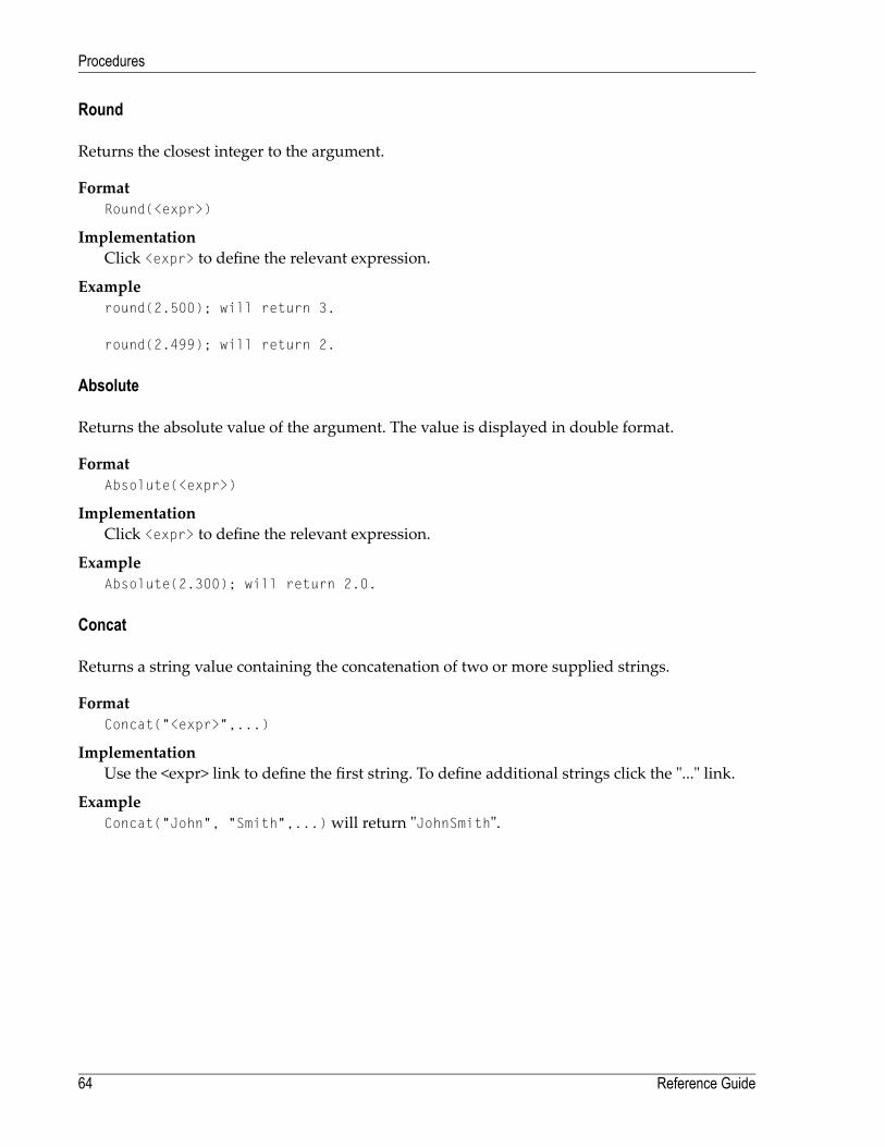
Round
Returns the closest integer to the argument.
FormatRound(<expr>)
ImplementationClick <expr> to define the relevant expression.
Exampleround(2.500); will return 3.
round(2.499); will return 2.
Absolute
Returns the absolute value of the argument. The value is displayed in double format.
FormatAbsolute(<expr>)
ImplementationClick <expr> to define the relevant expression.
ExampleAbsolute(2.300); will return 2.0.
Concat
Returns a string value containing the concatenation of two or more supplied strings.
FormatConcat("<expr>",...)
ImplementationUse the <expr> link to define the first string. To define additional strings click the "..." link.
ExampleConcat("John", "Smith",...)will return "JohnSmith".
Reference Guide64
Procedures

Trim
Trim expression returns a string containing a copy of a specified string with no leading or trailingspaces.
FormatTrim(<expr>)
ImplementationClick the <expr> to define the string expression to trim.
ExampleTrim(" John ")will return "John".
StrIn
StrIn expression returns the position of the first occurrence of one string within another.
FormatStrIn (<string> , <substring>, <case sensitive>)
StrIn (<string> , <substring>, <case insensitive>)
ImplementationClick <string> , <substring> to define the string in which to search and the string to searchfor. The expression will search for the first occurrence of the second string within the firststring. Toggle between case insensitive and case sensitive to determine case sensitivity.
ExampleStrIn ("Catwalk", "Cat") will return "0"
StrIn ("John", "Smith")will return" -1 "
StrIn ("Caterpillar", "pillar") will return "6"
SubString
SubString expression returns a substring that begins at a specified location, and has a specifiedlength.
FormatSubString (<string> , <start> , <length>)
ImplementationClick the links to define the original string, the start index and the required length of the sub-string.
ExampleSubString ("Caterpillar", 6, 6)will return "pillar".
65Reference Guide
Procedures
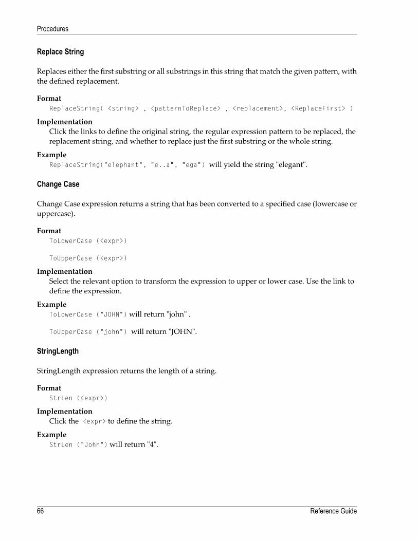
Replace String
Replaces either the first substring or all substrings in this string that match the given pattern, withthe defined replacement.
FormatReplaceString( <string> , <patternToReplace> , <replacement>, <ReplaceFirst> )
ImplementationClick the links to define the original string, the regular expression pattern to be replaced, thereplacement string, and whether to replace just the first substring or the whole string.
ExampleReplaceString("elephant", "e..a", "ega") will yield the string "elegant".
Change Case
Change Case expression returns a string that has been converted to a specified case (lowercase oruppercase).
FormatToLowerCase (<expr>)
ToUpperCase (<expr>)
ImplementationSelect the relevant option to transform the expression to upper or lower case. Use the link todefine the expression.
ExampleToLowerCase ("JOHN")will return "john" .
ToUpperCase ("john") will return "JOHN".
StringLength
StringLength expression returns the length of a string.
FormatStrLen (<expr>)
ImplementationClick the <expr> to define the string.
ExampleStrLen ("John")will return "4".
Reference Guide66
Procedures

Reverse
Reverse expression returns the reverse of a string expression.
FormatReverse (<expr> )
ImplementationClick the <expr> to define the string expression.
ExampleReverse ("caterpillar")will return "rallipretac".
FormatDate
FormatDate expression converts a date/time object into a date/time string, according to the givendate format.
FormatFormatDate (<date> , <format>)
ImplementationClick the links to define the expressions for the date/time object and format.
ExampleFormatDate (Now, "dd/MM/yyyy"), Nowexpression being the current date and time,will return"19/07/1982".
Format Number
Formats a number according to the given format number.
FormatFormatNumber( <number> , <format> )
ImplementationClick the links to define the expressions for the number and format.
ExampleFor example if the number 18734573.07 is required as 18,734,573.07, use the format "#,##0.00".Refer to Number Format for further explanation about the format syntax.
67Reference Guide
Procedures

Extract Number
Extract Number expression extracts a numeric value from a textual source number. When thereis more than one number, it extracts the first number it locates. This expressionmay be usedwhenneeding to perform calculations on the source number.
FormatExtractNumber (<expr>, Decimal:dot)
ImplementationSelect the relevant decimal symbol: dot or comma. The separator that you do not select willbe recognized as the thousand separator and will be removed. Click the link to define thesource expression.
ExampleWhen selecting the dot separator, ExtractNumber ("1,000,876.321") will return "1000876.321"When selecting the comma separator, ExtractNumber ("1.000.876,321") will return"1000876.321"
Character
Character expression returns an ASCII or Unicode Character according to the decimal represent-ation.
ImplementationInsert the character's ASCII code or Unicode value.
ExampleEnter "13", the text in theValue field will display "carriage return" indicating the functionality.
Test Case Specific Expressions
■ Wait Expression■ Test Screen Name■ Test Field Attribute■ Test Screen Content■ Is Member of Group■ Host Keys■ Position■ Screen Name■ Field Attributes■ Screen Properties■ Screen Buffer■ Field Content■ Find Field Index
Reference Guide68
Procedures
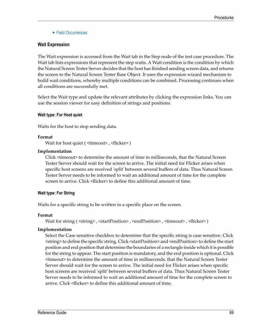
■ Field Occurrences
Wait Expression
TheWait expression is accessed from theWait tab in the Step node of the test case procedure. TheWait tab lists expressions that represent the step waits. AWait condition is the condition bywhichtheNatural Screen Tester Server decides that the host has finished sending screen data, and returnsthe screen to the Natural Screen Tester Base Object. It uses the expression wizard mechanism tobuild wait conditions, whereby multiple conditions can be combined. Processing continues whenall conditions are successfully met.
Select the Wait type and update the relevant attributes by clicking the expression links. You canuse the session viewer for easy definition of strings and positions.
Wait type: For Host quiet
Waits for the host to stop sending data.
FormatWait for host quiet ( <timeout> , <flicker> )
ImplementationClick <timeout> to determine the amount of time in milliseconds, that the Natural ScreenTester Server should wait for the screen to arrive. The initial need for Flicker arises whenspecific host screens are received 'split' between several buffers of data. Thus Natural ScreenTester Server needs to be informed to wait an additional amount of time for the completescreen to arrive. Click <flicker> to define this additional amount of time.
Wait type: For String
Waits for a specific string to be written in a specific place on the screen.
FormatWait for string ( <string> , <startPosition> , <endPosition> , <timeout> , <flicker> )
ImplementationSelect the Case sensitive checkbox to determine that the specific string is case sensitive. Click<string> to define the specific string. Click <startPosition> and <endPosition> to define the startposition and endposition that determine the boundaries of a rectangle insidewhich it is possiblefor the string to appear. The start position is mandatory, and the end position is optional. Click<timeout> to determine the amount of time in milliseconds, that the Natural Screen TesterServer should wait for the screen to arrive. The initial need for Flicker arises when specifichost screens are received 'split' between several buffers of data. Thus Natural Screen TesterServer needs to be informed to wait an additional amount of time for the complete screen toarrive. Click <flicker> to define this additional amount of time.
69Reference Guide
Procedures

Wait type: For cursor
Waits for the cursor to reach a certain position on the screen.
FormatWait for cursor ( <startPosition> , <endPosition> , <timeout> , <flicker> )
ImplementationClick <startPosition> and <endPosition> to define the start position and end position that de-termine the boundaries of a rectangle inside which it is possible for the string to appear. Thestart position is mandatory, and the end position is optional. Click <timeout> to determine theamount of time inmilliseconds, that theNatural Screen Tester Server shouldwait for the screento arrive. The initial need for Flicker ariseswhen specific host screens are received 'split' betweenseveral buffers of data. Thus Natural Screen Tester Server needs to be informed to wait anadditional amount of time for the complete screen to arrive. Click <flicker> to define this addi-tional amount of time.
Wait type: For Screen Id
Waits for a specific screen ID and all of the screen's identification strings to appear.
FormatWait for screen (<all expected screens>, <timeout> , <flicker> )
ImplementationClick <timeout> to determine the amount of time in milliseconds, that the Natural ScreenTester Server should wait for the screen to arrive. The initial need for Flicker arises whenspecific host screens are received 'split' between several buffers of data. Thus Natural ScreenTester Server needs to be informed to wait an additional amount of time for the completescreen to arrive. Click <flicker> to define this additional amount of time.
Wait type: While String
Natural Screen Tester Server waits while the screen displays the string of characters. The serverrealizes that all the data has arrived when the string is no longer displayed on the screen.
FormatWait while string ( <string> , <startPosition> , <endPosition> , <timeout> , <flicker> )
ImplementationSelect the Case sensitive checkbox to determine that the specific string is case sensitive. Click<string> to define the specific string. Click <startPosition> and <endPosition> to define the startposition and endposition that determine the boundaries of a rectangle insidewhich it is possiblefor the string to appear. The start position is mandatory, and the end position is optional. Click<timeout> to determine the amount of time in milliseconds, that the Natural Screen TesterServer should wait for the screen to arrive. The initial need for Flicker arises when specifichost screens are received 'split' between several buffers of data. Thus Natural Screen Tester
Reference Guide70
Procedures

Server needs to be informed to wait an additional amount of time for the complete screen toarrive. Click <flicker> to define this additional amount of time.
Wait type: While Cursor
Natural Screen Tester Server waits while the screen displays the cursor in a particular position.The server realizes that all the data has arrived when the cursor is no longer displayed on thescreen.
FormatWait while cursor ( <startPosition> , <endPosition> , <timeout> , <flicker> )
ImplementationClick <startPosition> and <endPosition> to define the start position and end position that de-termine the boundaries of a rectangle inside which it is possible for the string to appear. Thestart position is mandatory, and the end position is optional. Click <timeout> to determine theamount of time inmilliseconds, that theNatural Screen Tester Server shouldwait for the screento arrive. The initial need for Flicker ariseswhen specific host screens are received 'split' betweenseveral buffers of data. Thus Natural Screen Tester Server needs to be informed to wait anadditional amount of time for the complete screen to arrive. Click <flicker> to define this addi-tional amount of time.
Wait type: While Screen Id
The Natural Screen Tester Server waits while the screen is displayed. The server realizes that allthe data has arrived when one of the screen's identification strings are no longer displayed.
FormatWait while screen ( <timeout> , <flicker> )
ImplementationClick <timeout> to determine the amount of time in milliseconds, that the Natural ScreenTester Server should wait for the screen to arrive. The initial need for Flicker arises whenspecific host screens are received 'split' between several buffers of data. Thus Natural ScreenTester Server needs to be informed to wait an additional amount of time for the completescreen to arrive. Click <flicker> to define this additional amount of time.
71Reference Guide
Procedures

Wait type: While dynamic string
Wait while dynamic string ( <startPosition> , <endPosition> , <timeout> , <flicker> )
ImplementationClick <startPosition> and <endPosition> to define the start position and end position that de-termine the boundaries of a rectangle insidewhich it is possible for the dynamic string to appear.The start position is mandatory, and the end position is optional. Click <timeout> to determinethe amount of time in milliseconds, that the Natural Screen Tester Server should wait for thescreen to arrive. The initial need for Flicker ariseswhen specific host screens are received 'split'between several buffers of data. Thus Natural Screen Tester Server needs to be informed towait an additional amount of time for the complete screen to arrive. Click <flicker> to definethis additional amount of time.
Test Screen Name
Checks whether the selected screen matches the current host screen.
ImplementationSelect a screen to test.
Test Field Attribute
Boolean test of a selected attribute in the current screen/screen group, according to position orfield.
FormatIs/Is not <Field Attribute> in Position (row, column)
Is/Is not <Field Attribute> in Field(<select field>)
Implementation
1. Click Is/Is not to define the condition.
2. Select an attribute: protected, hidden, intensified, reversed video, background color, fore-ground color, content, blinking or underlined.
3. Select whether to retrieve the attribute of a specific position (specify the row and column)or field (select a field).
Reference Guide72
Procedures

Test Screen Content
Checks whether a certain text is within a defined rectangle or field in the current screen/screengroup.
FormatIs/Is not Content(text) in Rectangle(Start Position:(row, column), End Position:(row, column))
Is/Is not Content(text) in Position((row, column) (length))
Is/Is not Content(text) in Field(<select field>)
Implementation
1. Click Is/Is not to define the condition.
2. Click on <text> to define the relevant text.
3. Select whether the text is in a■ rectangle (specify the start and end row and column)■ specific position (specify the row, column and - optionally - length of the string)
Note: If length is not specified, the default value is 1, sowe recommend you providea meaningful value.
■ field (select a field)
Is Member of Group
Determines whether the current screen is a member of a specific Screen Group.
FormatIs/Is not Screen member of (Screen Group).
Implementation
1. Select the relevant Screen Group.
2. Click Is/Is not to define the condition.
73Reference Guide
Procedures

Host Keys
A free text editor that allows selecting host key constants.
ImplementationSelect a host key and then add tokens to use values from the context. Use replaceable tokens,using the Natural Screen Tester format $(<Replaceable Token Name>). Click Finish. Map thehost key expression to the relevant output.
ExampleEnter text and replaceable tokens:" Your account number is - $(number)". $(number) being areplaceable token.
Position
A row and column structure that defines a specific position.
FormatPosition( <row> , <column> )
ImplementationDefine the position by clicking the row and column expressions.
Screen Name
Returns the name of the current host screen.
Field Attributes
Returns the attributes of a position or field in the current screen/screen group.
FormatGet Attributes from Position(row, column)
Get Attributes from Field (<select field>)
ImplementationSelect whether to retrieve attributes from a specific position (specify the row and column) orfield (select a field).
The attributes that are retrieved are:■ Content - the content of the specific position (according to the defined length), or field.■ isProtected - True when protected, and False when unprotected.■ isIntensified - True when intensified, and False when not intensified.■ isHidden - True when hidden, and False when not hidden.■ isReversedVideo - True when reversed video, and False when not reversed video.
Reference Guide74
Procedures

■ isBlinking - True when blinking, and False when not blinking.■ isUnderlined - True when underlined, and False when not underlined.■ backgroundColor - returns the background color code and name (see list below).■ foregroundColor - returns the foreground color code and name (see list below).
Code #ColorCode #Color
8Gray-1None
9Light blue0Black
10Light green1Blue
11Light aqua2Green
12Light red3Aqua
13Light purple4Red
14Yellow5Purple
15Light white6Brown
7White
Note: These color codes are consistent with the codes that the Base Object fields return.
Screen Properties
Enables retrieving the following screen properties:
■ The row, column and/or field where the cursor is positioned.■ The width and height of the screen.■ Indication whether the screen is a window or not.■ Retrieves the window title.
Screen Buffer
Retrieves the screen content as an array, where each index in the array is a row of the screen. De-termine whether to retrieve the window content only or the whole screen.
FormatGet Screen Buffer(onlyWindowBuffer)
ImplementationClick onlyWindowBuffer to define a boolean expression which will determine whether to re-trieve just the window content or the whole screen.
75Reference Guide
Procedures

Field Content
Returns text from the current screen/screen group according to a position or field.
FormatGet Screen Content from Position(row, column)
Get Screen Content from Field (<select field>)
ImplementationSelect whether to retrieve text from a specific position (specify the row and column) or field(select a field).
Find Field Index
Finds the index of the first occurrence, within a multiple field, that matches a specified criteria.Select the relevantmultiple field and the type of attribute to search for, and then define the criteria.
FormatFind the index where(Is/Is not <field attribute>(<comparison type> <text>) inField (<select field>))
Implementation
1. Click Is/Is not to define the condition.
2. Select an attribute: protected, hidden, intensified, reversed video, background color, fore-ground color, content (define whether it is exact text or whether the field contains the text),blinking or underlined.According to the selected attribute, youmay be required to determinefurther search parameters such as colors, the specific screen content etc.)
3. Select the relevant multiple field.
Field Occurrences
Returns the number of instances of a multiple field in the current screen\screen group.
FormatCount of Field(<select field>)
ImplementationClick on select field. Select a specific screen\screen group and then select a field from the listof fields.
Reference Guide76
Procedures

Web Procedure Specific Expressions
■ Test Web Element Exists■ Web Element Content
Test Web Element Exists
Boolean test of a selected XPath in the current page. This function does notwait for all the elementsof the page to be loaded and is carried out straight away.
FormatIs/Is not Web Element (<XPath>) exists
Implementation
1. Click Is/Is not to define the condition.
2. Click the XPath to open the Free Text dialog box and enter the XPath (you can copy-pastethe XPath of an existing element by right-clicking an element and selecting Copy XPath toClipboard).
Web Element Content
Returns the content of the element according to the selected XPath. If the element is not foundafter a certain amount of time (by default 30 seconds), this expression will timeout. This time canbe changed in the <Natural Screen Tester installation>/config/gxconfig.xml file:
<MainConfiguration>...<ServerConfiguration>...
<webProcedureConfig><waitElementTimeout>30000</waitElementTimeout>
</webProcedureConfig></ServerConfiguration>
</MainConfiguration>
FormatGet Content from Web Element (<XPath>)
ImplementationSelect the XPath from which to retrieve the content.
77Reference Guide
Procedures

Program Procedures
Double-click on the relevant Program Procedure from within the Repository. The Editor areadisplays the Procedure Program.
LocationFully qualified path of program in the host file system.
Code languageRPG or COBOL.
NameName of parameter
TypeData type of parameter
UsageSelect the parameter usage: input, output, or input/output.
Reference Guide78
Procedures

Expose asSelect which parameters are exposed to the end user. By default, a parameter is exposed ac-cording to its usage (input, output, etc.)
LengthEnter the parameter's length.
For RPG use only: Youmay either type a number or select from the drop-down list a referenceto another numeric parameter.
Output size (optional)For RPG use only: If the output size for this parameter is different from its length (array etc.),enter the expected output size. You may either type a number or select from the drop-downlist a reference to another numeric parameter.
Count by (optional)If this parameter is an array, enter the number of members in this array. Either type a numberor select from the drop-down list a reference to another numeric parameter for dynamic arrays.For dynamic arrays you may also specify the minimum or maximum array boundaries.
Default value (optional)Enter a default value for this parameter.
Precision (optional)For numeric parameters, enter the number of digits that follow the decimal point.
Original Statement (optional)If imported by the program wizard, this box will display the original statement from the pro-gram's source file for this parameter.
79Reference Guide
Procedures

80

8 Connection Pools
■ General ......................................................................................................................................... 82■ Pool .............................................................................................................................................. 82■ Keep-alive ..................................................................................................................................... 83■ Connection Information Sets .............................................................................................................. 83■ Pool Size Control Policy Considerations ............................................................................................... 84■ Navigation ..................................................................................................................................... 85
81

A connection pool enables you to immediately get a host connection that is ready in a specificscreen, the “initial screen”. This saves the time of establishing the connection with the host andnavigating to the relevant screen.
See also Connection Pools in the Designing and Developing a Test Case documentation.
General
Log levelIt is possible to set a different detail of logging for each connection pool. The server loggershould be set to Info log level at least, in order to see connection pool logs.
Initialization mode
ManualAn administrator manually initializes the connection pool.
When first accessedWeb applications or sessions that connect to the connection pool on the first call.
AutomaticAutomatically initializes the connection pool when the test project is loaded.
Pool
Disconnect after usageWhen the check box is selected, a connection will not be used again after it is returned to thepool. The termination path will be executed and then the connection will be disconnected. Anew connection will be initialized if needed, according to the connection pool size definitions.
When the check box is not selected, the recycle path (it is recommended to define a recyclepath when Disconnect after usage is not selected) is performed. The termination path will beexecuted once the connection pool stops. For more information see Defining a TerminationPath.
User wait for connection timeoutThe time, in milliseconds, that a user should wait to get a connection from the server beforegiving up. Leaving the box empty (or 0) sets no timeout at all.
Delay between connection attemptsThe minimum delay time, in milliseconds, between any two consecutive connection creationattempts. Leaving the box empty (or 0) sets no delay at all.
Pool size typeFixed: Constant number of connections (no pool size policy).
Reference Guide82
Connection Pools

Limited: Number of connections is bound in a range.
Flexible: Number of connections is not bound by the pool.
Number of connectionsWhen selecting Fixed as the size type, select the fixed number. When selecting Limited orFlexible enter the minimal and maximum number of connections in the pool as required.
Available connectionsNot relevant when selecting Fixed as the size type. This field determines the pool size policy,see Pool Size Control Policy Considerations.
Minimal number of available connections in the pool. If the number of available connectionsin the pool falls below this number, new connections will be created until the minimum isreached.
Maximal number of available connections in the pool. If the number of available connectionsin the pool exceeds this number, some connections will be terminated until the maximum isreached.
Keep-alive
PathA path that keeps the connection at the connection pool initial screen. Use the folder selectionicon to select paths from different folders.
IntervalThe time, in minutes, that an available connection may stay idle. When this time elapses, akeep-alive path is executed.
Connection Information Sets
A connection information set supplies a pool of possible connection parameters required for theinitial connection to the host (such as the device type or host address) and for the execution of theconnection pool initialization path when it exists (such as the required user name and password).See also Connection Information Sets in the Designing and Developing a Test Case documentation.
Select setSelect an existing Connection Information Set, or create a new one by selecting "<new set>"and pressing the button, labeled "New". To edit existing information set, select it in the combobox, and click the button (now labeled "Properties").
83Reference Guide
Connection Pools

Delay after using a setThis delay takes place after a connection is terminated, and before a new connection can beinitialized using the same parameter set. However, the delay will not occur if the connectioninformation row has an unlimited repeat value (0). This feature is required for cases wherethe host can't initialize a new connection immediately after closing the current one, using thesame parameters (user and password, device name, etc.).
Note: Changes to the pool's parameters will take place immediately, though the poolmay take a while to fully adjust to the new configuration. Furthermore, changes willnot cause the sudden disconnection of current active users.
Pool Size Control Policy Considerations
A simple (but not recommended) size control policy would be to set the minimal and maximalnumber of available connections with the same value. Under such a policy, the pool will try toalways have a fixed number of available connections at hand. Therefore, when a client receives aconnection, the number of available connections is reduced by one. The pool will initialize a newconnection. When the client returns a connection, the pool recycles it and then it has one extraavailable connection. The pool will then terminate one of its connections to maintain the fixednumber of available connections.
As far as the host server is concerned, every user that used the connection pool requires a newconnection and initialization process (besides the constant set of "buffered" connections). However(unless working with a disconnect after usage policy), other pool size policies can diminish theamount of work required from the host server for the same amount of users.
Let n be the minimal, and n+k the maximal numbers of available connections. Usually there willbe n to n+k available connections at hand. When a client receives a connection, a new connectionwill only be created if there were exactly n available connections. Similarly, a connection will beterminated after a connection is returned to the pool only when there are already n+k availableconnections in the pool.
Let d be the maximal absolute difference between the number of connections taken from the pooland the number of connections returned to it during every moment in a given period. As long asd < k no new connections to the host server are required, no matter how many users are servedduring that time.
The chart provides an example of the possible effect of pool size policy. The blue line representsthe number of users connected at anymoment. The first pool is configured to have three availableconnections at any given time. The secondpool has a range of available connections: two (minimum)to five (maximum). The size of the first pool (red line) varies exactly according to the activity ofthe users. It requires the host to initialize and logoff 19 additional connections while serving 40users. The second pool is more stable in size (green line), and requires only five additional connec-tions and destroys only three, serving the same amount of users.
Reference Guide84
Connection Pools

To conclude, we see that using a range of available connections (as opposed to holding a fixedsize buffer) can dramatically reduce the number of connections and disconnections from the hostserver.
Note: This is true only when using a recycle path instead of disconnect after usage policy.
Connection Information Sets may affect the actual maximum size of the pool. For example whena limited number of users and passwords with a repeat limit of one is defined in the connectioninformation set, themaximumnumber of possible connectionswill be the number of users definedin the connection information set even if the defined pool size is flexible. Refer to Connection In-formation Set for further details.
Navigation
InitializationA path that can be executed on any new connection to the host that navigates the connectionto one of the Initial Screens.
Initial ScreenThe initial screen is the first screen after the Initialization Path ends. The connection pool initialscreen can be selected from the identified screens list. The Test Project Map can be used forthis purpose.
RecycleA path that can be executed on any used connection returned to the pool that navigates theconnection to one of the Initial Screens.
85Reference Guide
Connection Pools

Run recycle anywayWhen checked, recycle pathwill always be performed after the connection has been used, evenif the connection is in the initial screen.
TerminationA path that can be executed on any connection to the host (used or new) that should be per-formed before destroying a connection (for example, a host side logout procedure).
Reference Guide86
Connection Pools

9 Connection Information Sets
A connection information set supplies a pool of possible connection parameters required for theinitial connection to the host (such as the device type or host address) and for the execution of theconnection pool initialization path when it exists (such as the required user name and password).See also Connection Information Sets in the Designing and Developing a Test Case documentation.
Table AreaThere are two initial columns and one row in the table. The ID column indicates <default> forthe initial row (cannot be deleted). Other rows are automatically assigned a numeric ID. TheRepeat column can be edited (but cannot be deleted), and states the maximum number of hostconnections that can use the information row simultaneously. More columns and rows canbe added to the table.
Add RecordAdds a new row to the table. Row ID is set automatically.
Delete RecordDeletes selected row or rows. The default row cannot be removed.
Define ColumnsEnables defining a column in the table. The Column Selection dialog will open to allow youto select or remove columns.
In the column selection dialog box, entities can be added as table columns: connection para-meters, fields and variables. Connection parameters are parameters that are required for ini-tializing a sessionwith the host such as the device name or host name. The parameters definedhere override the general parameters defined in the test project configuration. Fields andvariables provide the data required by the initialization path that is used in connection pools.Use fields or variables in accordance with the requirements and definitions of the relevantpath. Many times one of the columns contains password information. It is recommended toprotect such the values entered in this column by applying the Password column feature.
Set PasswordSets the column as a password column, making it protected.
87

Set Default ValuesIt is possible to set default values for the parameters/variables in the Connection InformationSet. When clicking this link, a dialog box is displayed enabling you to enter default values foreach of the columns.
Reference Guide88
Connection Information Sets

10 Natural Screen Tester Log Files
■ Server Log ..................................................................................................................................... 90■ Connection Pool Log ........................................................................................................................ 90■ Logging a Message from within a Procedure ......................................................................................... 91■ Test Case Procedure Failure Log ........................................................................................................ 91■ GCT Trace File ............................................................................................................................... 91
89

Natural Screen Tester provides a number of different tools that can help to log, trace and analyzeperformance and functionality.
Note: Log and trace files can contain sensitive personal data (for example user ID, IP address,etc.).We recommend you check the different trace opportunities provided byNatural ScreenTester and delete log and trace files if they are no longer needed. Natural Screen Tester willnot delete these files automatically; this is your responsibility as user. Use the appropriatetools of the respective operating system.
Server Log
The Server Log includes information as to the Server's activities and problems. The contents ofthe server log file are defined according to the settings configured in the Server Parameter>Lognode. The Server Log can be accessed from Natural Screen Tester Designer or via an externalbrowser. Administrators who do not have Natural Screen Tester Designer will access the ServerLog from theDesigner. Administratorswho do not haveNatural Screen Tester Designerwill accessthe Server Log via an external browser.
There are several possible levels and each level includes the levels above it. For example, the Debuglevel also logs Normal, Warnings and Errors Only levels. See also Configuring the Server: Log |Viewing the Server Log in the Getting Started documentation.
Connection Pool Log
A log used for fine-tuning connection pool parameters or identifying problems of the differentconnection pools is written within the server log. The server log should be set to no less that theInfo log level, in order to see connection pool logs. Once the project is in the production phase,Error level is the recommended level to use. It is possible to set a different detail of logging foreach connection pool: None, Errors, Warnings, Information and Details.
See also Connection Pools: General Parameters.
Reference Guide90
Natural Screen Tester Log Files

Logging a Message from within a Procedure
As part of the procedure work flow definitions, it is possible to define that at some point in theprocedure a message will be sent to the log. This is implemented using the Log Message Node(Refer to Working with Procedure Nodes and to General Nodes (Relevant for both Flow and TestCase Procedures), Test Case Procedure Nodes and Flow Procedure Nodes.
Test Case Procedure Failure Log
Natural Screen Tester enables generating a log that includes debug data regarding proceduresthat fail in runtime. The log includes a snapshot in ASCII characters of the screen that caused thefailure.
To log data regarding procedures that fail in runtime
1 In the <nsr_home>/config/log/gxlog_config.xmlfile under the com.sabratec.util.flow.error_trackingcategory tag, change the <level value="off"/> line to be commented and uncomment the <!-level value="debug"/--> line.
2 Restart the Natural Screen Tester Server.
The log will be created in the <nsr_home>/log directory, and the file names will have the fol-lowing format: debugging_error_in_%I_%t.log, %I being identifying information about theuser and procedure name, and %t being the timestamp. The location and name of the file canbe changed in the gxlog_config.xml file.
GCT Trace File
The GCT Trace File log enables recording a file, which traces the connection communication(connection pool or user) between theNatural Screen Tester server and the host, for each connection.It is possible to define whether a single trace file will be created, replacing the previously savedfile or whether the data will be saved to a new file on every new connection or session. Identifyingthe separately saved files is possible by inserting identifying parameters in the file name (the sessionID, creation time and/or connection ID). It is highly recommended to create a separate file for eachsession/connection or creation time. Note that trace files can be created from within the sessiondefinition overriding the application definition. This is recommended as it does not conflict withother existing sessions.
Note: Log and trace files can contain sensitive personal data (for example user ID, IP address,etc.).We recommend you check the different trace opportunities provided byNatural Screen
91Reference Guide
Natural Screen Tester Log Files

Tester and delete log and trace files if they are no longer needed. Natural Screen Tester willnot delete these files automatically; this is your responsibility as user. Use the appropriatetools of the respective operating system.
Refer to Recording Trace Files in the Designing and Developing a Test Case documentation for detailsregarding recording trace files.
Refer to the Session View in the Designing and Developing a Test Case documentation for detailsregarding overriding properties per session and also for details on navigating within a session inreplay mode.
Reference Guide92
Natural Screen Tester Log Files

11 Database Entity
FolderThe folder where the database is located.
UsernameThe username required to connect to the database (optional).
Password
URL additional parametersAdditional parameters needed for the database connection (optional).
DriverThe connection driver used to access the database. You can choose a pre-defined driver usingthe combo box or supply a custom one. It may be required to supply the driver itself toNaturalScreen Tester Server.
Requires Driver FilesDriverDatabase
org.apache.derby.jdbc.EmbeddedDriverApache Derby
Yescom.Microsoft.jdbc.sqlserver.SQLServerDriverSQL Server
Yesoracle.jdbc.driver.OracleDriverOracle
Yesorg.git.mm.mysql.DriverMySQL
YesCOM.ibm.db2.jdbc.app.DB2DriverDB2
URLThe connection prefix required to connect to the database. Choose a pre-defined prefix fromthe combo box or supply a custom one.
93

94

12 Troubleshooting
■ Test Project Map ............................................................................................................................. 96■ Connection Pools ............................................................................................................................ 96■ Natural for UNIX APX Component ...................................................................................................... 98■ Web Procedures ............................................................................................................................. 99■ Error Messages ............................................................................................................................. 100
95

Test Project Map
An individual screen thumbnail within the Test Project Map can indicate problems or incompat-ibility between the defined identifiers and the screen image attached to the screen. Such problemsare indicated by a red frame around the specific screen.
Possible problems:
■ Incompatibility between the defined identifiers and the screen image attached to the screen.This can happen as a result of creating a screen and then manually changing an identifier.
■ The screen suits the screen image, but there is a screen which is more suitable or identical to thescreen image. Look at the name of the screenwhich is on the screen image and check that it suitsthe current screen. Note that the name which is on the screen image indicates how the serveridentified this screen image given all current screen definitions.
See Test ProjectMap in theDesigning andDeveloping a Test Casedocumentation formore information.
Connection Pools
How to CheckPossible ReasonsExplanationSymptom
Try to connect to the hostwithout thepool.
Host is unavailable.Host sessions becomebroken if they cannot get to
All myconnectionsare broken Ready state. Readymeans
that:Create a connection outside the pool,run the initialization path and verifyit gets to the "initial screen".
Initialization path needs tobe modified.
1. The connection is alive.
2. If an "initial screen" isdefined by the pool, thesession must get there.
Observe the state of the Disconnectafter usage checkbox in pool tab ofthe connection pool.
TheDisconnect afterusage option is checked.
The pool may beconfigured to allowreusing a host connection
Connectionsdisconnectafter use but Iwant to reusethem
that was used by aprevious user. This would
Capture a trace file for the useractivity and recycle path. Observe
The logic of the useractivity or the recycle path
require returning the that the host session is not terminatedcauses a disconnectionfrom the host.connection to the initial
screen, either byduring the invocation of user activityor the recycle path.
implementing a robustCapture a trace file for the useractivity and recycle path. Observe
When a connection isreturned to the pool and it
navigation logic inside theinvoked procedure or inthe recycle path. that at the end of the user activity and
Reference Guide96
Troubleshooting

How to CheckPossible ReasonsExplanationSymptom
the recycle path invocation, theconnection is in the initial screen.
is not in the "initial screen",and there is no recycle paththat successfully navigatesto the initial screen.
Verify the existence of an "endsession" node in the flow procedure
A flow procedure createsan emulation session on a
Upon finishing the useractivity on a pool
ConnectionsremainActiveafter use that creates the emulation session.pool connection, but theconnection, the state of the
Verify that the "end session" node is"end session" node is notcalled on that session.
connection would changeaccording to the pool reached by capturing a trace file orconfiguration and the state by logging the invocation of the flow
procedure.of the user session. Thestate of the connectionwould remain active if thesession used by the poolhas not ended.
Capture a trace file that includes theinvocation of the termination path
An exception in thetermination path is causing
Apoolmaybe terminatinga connection based on the
Connectionsremain
and observe that the path hasthe host connection topool's configuration,Terminatingafter use completed successfully. Search foreither get stuck or toconnection count and the
exceptions in the server logs thatterminate beforecompleting the path.
status of the session.Whendoing so, the connection occurred during the invocation of the
termination path.status would become"Terminating" and thetermination path wouldrun on the connection.After the termination pathis completed, theconnection is removedfrom the pool.
Capture a trace file for the useractivity, observe the last packet
The host is disconnectingthe pool connection based
A usedconnection is
transmissions between the server andon the user activity or dueto the host state.
disconnectingwhile beingused
the host. Look in the server log for anerror indicating a socket close aroundthis timestamp. Also ask the hostadministrator to inspect the host's logfor disconnections.
When capturing trace files, youwould notice a trace file created at
Another host connection isusing the same host
the time when a previous trace file iscredentials/device nameand hijacking the session. closed. Both traces will include send
sections containing the samecredentials or device name.
97Reference Guide
Troubleshooting

Note: When recording trace files to capture the symptomsmentioned above, we recommendusing the following variables in the trace file name: connection ID (%c), session ID (%u),creation time of file (%t). See Recording Trace Files for more information.
See Connection Pools in the Designing and Developing a Test Case documentation for more inform-ation.
Natural for UNIX APX Component
To troubleshoot problems in the APX component's functionality it is possible to define tracing itsactivity. The daemon and the Natural application with the APX lib can be traced separately. Inorder to determinewhich of the two components' activity should be traced follow these guidelines:when the problem seems to be to do with connecting the Natural Screen Tester Server to the APXdaemon (including authentication problems), trace the daemon component. For any other problemstrace theNatural application. Note that it is not recommended to use the trace file in the productionenvironment on a regular basis.
To trace the APX daemon
1 Go to the $NATDIR/$APXNODE directory.
2 Edit the apxsrvd.sh file.
Find EXECUTABLE=apxsrvd, and change it to EXECUTABLE=apxsrvd.tr
3 Define the following environment variables (the following is an example of how these shouldbe defined in sh/bash):
> PT_TRACELEV=i6000> SAGTMP=$HOME/tmp> export PT_TRACELEV> export SAGTMP
The trace files are created in the $SAGTMPdirectory. In the example above this is $HOME/tmp.
4 Restart the daemon:
> apxsrvd.sh servicename stop> apxsrvd.sh servicename start
or
Reference Guide98
Troubleshooting

> apxsrvd.sh portnumber stop> apxsrvd.sh portnumber start
To trace the Natural Application with the APX library
1 Go to the $NATDIR/$APXNODE directory.
2 Edit the apx.sh file.
$NATDIR/$NATVERS/bin/natapx parm=$PARAMETERS etid=$$ >/dev/null 2>&1
Change natapx to natapx.tr
Uncomment (by removing the # from the beginning of the rows) the TRACE section.
The trace files are created in the $SAGTMP directory.
By default it is $HOME/tmp. It will take effect when next connecting to the daemon.
See Setting up the APX Component for more information.
Web Procedures
SeeWeb Procedures for more information.
What to do when the Web Procedure Fails to Run
The Web Procedure can fail to run for a number of reasons such as an element cannot be foundon the page or unexpected behavior when running JavaScripts. Some of these issues can be solvedby adjusting parameters in the <NSR-installation>/config/gxconfig.xml file. Following is a list ofpossible problems with a recommendation as to what to do and when relevant, which parameterto configure. Below is a snipet of the code as it appears within the gxconfig.xml file.
Timeout error:When running theWeb Procedure, sometimes an errormessage is displayed indic-ating that a timeout occurred, and that the procedure failed and did not run successfully. This canbe for a number of reasons:
■ A specific element used in the procedure was not found on the page. In this case, you shouldtry the following:
1. The XPath defined may not capture the correct element. Run the procedure from within theDesigner and follow the output in the Console area.
2. Refine the XPath to make it more robust. Refer toWhat is an XPath?
3. Change the server log level to "trace" to help you understand where the problem may lie.
99Reference Guide
Troubleshooting

4. If you know that this element is on the page, you should try to change the waitElementTimeoutparameter and see if after extending this time the element is found.
■ Required resources are not loaded on the pagewithin a certain amount of time. You can confirmthat this is your problem by setting the log level to "trace" and see that the actions/web elementcontent retrieval is performed on the previous page. Change the navigationTimeout parameterto try and solve this.
Unexpected behavior when running JavaScript methods: If in a scenario which relies on the ex-ecution of a JavaScript method, the results are not as expected. Changing the javascriptTimeoutmay solve this.
CSS related problem:When there is a scenario that relies on the evaluation of CSS rules, and theresults are not as expected, setting the cssEnabled parameter to enabled may solve this.
<MainConfiguration>...<ServerConfiguration>...
<webProcedureConfig><waitElementTimeout>30000</waitElementTimeout><navigationTimeout>90000</navigationTimeout><javascriptTimeout>30000</javascriptTimeout><cssEnabled>false</cssEnabled>
</webProcedureConfig></ServerConfiguration>
</MainConfiguration>
Error Messages
What should I do?Possible ReasonsExplanationError MessageRC
Check the NaturalScreen Tester Server
May occur as a resultof incompatible clientand server version.
Error communicating with NaturalScreen Tester Server
ERRORSOCKET
5005
version (see server log)and the client version(see client log) andmakesure they are of the sameversion and buildnumber.
Catch this error in theclient web application
Host failure ornetwork issue that
If the host decides to close theconnection with the Natural Screen
and act accordingly.made it offline.Tester Server, the session in the serverLook into the host logsfor more details.
Probably more detailsin the host logs.
will be disconnected and the clientwill receive a 5005 error, indicatingthat theNatural Screen Tester sessionis no longer active.
Reference Guide100
Troubleshooting

What should I do?Possible ReasonsExplanationError MessageRC
Check user credentials.When opening a Web applicationpage we get the following error:
ERRORCANNOT
5002 1. Missing orinsufficientpermissionsCONNECT
TO HOST 2. The host is offline.
3. Password expired(Natural underUNIX).
Look for "If" block withthe empty string or look
Usually these errorsappear aftermigrating
In earlier versions, NULL and emptystring were almost the same. From
Errorevaluating theexpression
n/a
for inputs without theprocedures, see theversion 9.8 they are not, and youdefault value. The errorerror message in the
log for more details.should actively use options likeisNull() or put in a default valueto avoid these errors.
logmessage should helpyoufigure outwhere thisis coming from.
Look into the server'slaunch config files
The JVM's XMXparameter memoryallocation is low.
Usually happens due to a Java heapspace problem.
The repositoryis notavailable
n/a
(startup.bat /GXApplinXService.ini)and increase the -xmxvalue of the JVM.
Open the browser'sdeveloper tools and use
Could be caused by ahost key not
The Framework's JavaScript engineencountered an error.
GeneralJavascripterrors
n/a
them to debug theresponding, or screenscenario until youpinpoint the root cause.
that wasn't refreshedafter entering a valueto an input field.
Check connection poolconfiguration. If it is set
Connection pool isn'tactive.
Service fails to run on the local server.The error code should be"ERROR_SERVICE_NOT_ACTIVE".
ProcedureException:Cannot run
5051
to "when first accessed",change it to "manual".procedure
proc_name,error gettinghostconnection,error code
Open the Hostconfiguration and
Replayerconfiguration doesn't
When running a trace file from thedesigner there should be a match
Replayerconfiguration
n/a
change the hostmatch the current hostbetween the Replayer to the currenthost configuration.
doesn't matchthe current configuration according
to the trace file.configuration. Forexample, theReplayerhost
configuration. Expected Model is 5and the Hostconfiguration Modelis 2.
101Reference Guide
Troubleshooting

102

13 List of Appendices
Appendix A: Reserved Words in Natural Screen Tester
Appendix B: Security in Natural Screen Tester
Appendix C: Natural for UNIX Installation
Appendix E: SSL Encryption Modes Supported by Natural Screen Tester
Appendix F: Syntax and Format Reference
Appendix G: ASCII Character Table
Appendix H: SDFX File Format Definition
Appendix I: Dynamic Field Mapping Limitations
Appendix K: Host Supported Code Pages
103

104

14 Appendix A: Reserved Words in Natural Screen Tester
The following words cannot be used as the name of an entity or test project:
■ abstract■ addressof■ App_Code■ App_Data■ as■ asp■ aspx■ assert■ base■ bool■ boolean■ break■ byte■ case■ catch■ char■ checked■ class■ clear■ close■ config
105

■ const■ context■ continue■ cs■ css■ date■ decimal■ default■ delegate■ delete■ dim■ do■ document■ double■ else■ end■ enum■ escape■ eval■ event■ exception■ explicit■ extends■ extern■ FALSE■ field■ final■ finally■ fixed■ float■ for■ foreach■ friend
Reference Guide106
Appendix A: Reserved Words in Natural Screen Tester

■ function■ get■ goto■ handles■ if■ images■ implements■ implicit■ import■ in■ index■ inherits■ instanceof■ int■ interface■ internal■ is■ java■ js■ jsp■ lock■ long■ me■ mustoverride■ mybase■ myclass■ namespace■ native■ new■ next■ nothing■ notoverridable■ null
107Reference Guide
Appendix A: Reserved Words in Natural Screen Tester

■ object■ open■ operator■ out■ overridable■ override■ overrides■ package■ page■ params■ private■ protected■ public■ put■ readonly■ redim■ ref■ return■ sbyte■ screen■ sealed■ shadowing■ short■ sizeof■ stackalloc■ static■ strictfp■ string■ struct■ sub■ substring■ super■ switch
Reference Guide108
Appendix A: Reserved Words in Natural Screen Tester

■ synchronized■ target■ this■ throw■ throws■ tostring■ transient■ TRUE■ try■ typeof■ uint■ ulong■ unchecked■ undefined■ unsafe■ until■ ushort■ using■ value■ var■ vb■ virtual■ void■ volatile■ while■ window■ withevents■ write
109Reference Guide
Appendix A: Reserved Words in Natural Screen Tester

110

15 Appendix B: Security in Natural Screen Tester
■ End-To-End Security ...................................................................................................................... 112■ Host <> Natural Screen Tester Server ................................................................................................ 112■ Development Time ......................................................................................................................... 112■ Connection Pools .......................................................................................................................... 113■ Running Natural Screen Tester Server with a Java Policy File ................................................................. 113
111

End-To-End Security
Natural Screen Tester multi-tier architecture supports end-to-end security by utilizing encryptionand industry-standard, secured protocols within each layer of communication. The followingdocument details the security measures that are available for each layer, as well as additional se-curity mechanisms available in other Natural Screen Tester components.
Natural Screen Tester server and clients support the ciphers defined at JVM level. See list of sup-ported SSL cipher suites.
Host <> Natural Screen Tester Server
Communication between Natural Screen Tester Server and the host can be encrypted using SSLV3. Both client and server authentication are supported. SSL X509 certificate is stored usingstandard Keystore implementations (JCEKS).
This feature is available for any host that supports SSL V3 communication, however, this has onlybeen tested on Mainframe hosts. It is also possible to use the secured protocol SSH V2.
To configure an SSL connection between the host and Natural Screen Tester server
■ Refer to Configuring the SSL Connection.
Development Time
Natural Screen Tester allows managing password-protected users, groups and their permissions.It is possible to define certain permissions to a group, and then associate users with this group,giving the user the permissions defined for this group or to define specific users permissions. Eachuser/group can be assigned with read/write permissions at the application or folder level. Theusers' definitions are saved in an encrypted configuration file.
It is also possible to define users based on Integrated Windows Authentication (formerly NT Au-thentication).
Reference Guide112
Appendix B: Security in Natural Screen Tester

Connection Pools
It is possible to specify passwords of host users as part of the connection information sets of con-nection pools (to enable connection pooling with automatic login to the host application). Thesepasswords are encrypted and saved in the application's repository.
Running Natural Screen Tester Server with a Java Policy File
In order to run theNatural Screen Tester serverwith a Java securitymanager enabled, the followingflags should be appended to the Start_Process_Parameters in the <Natural Screen Tester installa-tion>\bin\start-gxserver.bat file, or to the JAVA_OPTS in the <Natural Screen Tester installa-tion>\bin\start-gxserver.sh file or to the Start_Process_Parameters in the GXNatural ScreenTesterService.ini file:
-Djava.security.manager -Djava.security.policy=./conf/catalina.policy
In the policy file (specified in the path above) the following permissions are set inside a grantsection (if a different policy file is used, one should add the following manually):
permission java.net.SocketPermission "localhost:3323" , "listen,resolve,accept";permission java.net.SocketPermission "localhost:*" , "resolve,accept";permission java.net.SocketPermission "<host name>:<host port>" , "connect,resolve";permission java.io.FilePermission "${com.sabratec.gxhome}/-", "read, write, delete";permission java.io.FilePermission "${catalina.home}/-", "read";permission java.io.FilePermission "${java.home}/../-", "read"; permission java.io.FilePermission "${java.io.tmpdir}/" , "read, delete, write";permission java.io.FilePermission "${java.io.tmpdir}/-" , "read, delete, write";
//Natural Screen Tester Xstream usage. Used mostly by Natural Screen Tester ↩configuration persist to XMLpermission java.lang.RuntimePermission "accessClassInPackage.sun.misc";permission java.lang.RuntimePermission "accessClassInPackage.sun.reflect";permission java.lang.RuntimePermission "accessClassInPackage.sun.io";permission java.lang.RuntimePermission "accessClassInPackage.sun.logging.*";permission java.lang.RuntimePermission ↩"defineClassInPackage.org.apache.jasper.runtime";permission java.lang.RuntimePermission "accessDeclaredMembers";permission java.lang.RuntimePermission "createClassLoader";permission java.lang.reflect.ReflectPermission "suppressAccessChecks";permission java.lang.RuntimePermission "reflectionFactoryAccess";permission java.io.SerializablePermission "enableSubclassImplementation";permission java.lang.RuntimePermission "getClassLoader";// For using Log4Jpermission java.lang.RuntimePermission "defineClassInPackage.java.lang";
113Reference Guide
Appendix B: Security in Natural Screen Tester

// Used for showing the server icon in the system tray. Uncomment if needed.// permission java.lang.RuntimePermission "loadLibrary.GXUtil";// permission java.lang.RuntimePermission "modifyThreadGroup";
permission java.io.SerializablePermission "enableSubstitution";permission java.sql.SQLPermission "setLog";permission java.util.PropertyPermission "com.sabratec.*", "read,write";permission java.util.PropertyPermission "com.softwareag.*", "read,write";permission java.util.PropertyPermission "*", "read";permission java.util.PropertyPermission "org.apache.adb.properties", "read,write";permission java.util.PropertyPermission "javax.xml.registry.ConnectionFactoryClass", ↩"write";
Note: lines with a close that starts with a single '<' character, should be edited according tothe text inside the close.
When Natural Screen Tester is running with SSL support, the following should be added as well:
permission java.io.FilePermission "${java.home}/jre/bin/keytool" ,"execute";
Reference Guide114
Appendix B: Security in Natural Screen Tester

16 Appendix C: Natural for UNIX Installation
■ Installing APX Component for Natural UNIX Protocol ............................................................................ 116■ Installing Natural for Natural Screen Tester on OpenVMS Hosts .............................................................. 123■ Closing the Natural Application and Natural in Error Situations ................................................................ 127■ Restrictions .................................................................................................................................. 128
115

Installing APX Component for Natural UNIX Protocol
When the host system on which you run your Natural applications is a UNIX system, additionalsoftware for theNatural UNIX protocol has to be installed on the host. TheNatural UNIX protocolmodules are shipped together with Natural for UNIX.
The protocol enables:
■ The option to change the host password via the Natural Screen Tester Base Object.■ Support for a non standard screen size.■ User permissions are now received directly from the host. Note that currently it is not possibleto log in to the host without providing a user name and password unless you use a customizedUser Exit authentication function.
■ Host keys are automatically recognized byNatural Screen Tester and do not need to be identifiedaccording to their pattern.
■ It is now possible to define the authentication method and authentication localization texts.■ The configuration has been improved. It is possible to specify the Natural parameter file inNatural Screen Tester Designer, using the same port for a number of applications in parallel,without making changes in the host.
■ Prerequisites■ Setting up the APX Component■ Directories■ Configuration Files■ Working with the APX UNIX Component
Prerequisites
■ Supported Operating SystemsThe same platforms as those supported by Natural for UNIX.
■ Other Software ProductsNatural Version 6.3.2 or above for UNIX.
■ LinkerA linker (for example, lD or cc) and the command make must be available in the system.
Reference Guide116
Appendix C: Natural for UNIX Installation

Setting up the APX Component
Setting up APX on UNIX consists of the following steps
1 Stop the NAT UNIX apxsrvd Daemons
Note: This step is only required for an upgrade installation. It is not requiredwhen youinstall Natural for UNIX for the first time.
Stop the apxsrvd process using one of the following commands: apxsrvd.sh servicenamestop
or
apxsrvd.sh portnumber stop
Repeat this command for each service that has been started.
2 Establish the Environment
Ensure that the environment definitions, as described in setup.txt in the root directory of theNatural CD, are correct and set.
Note: Special note for Red Hat Enterprise Linux AS: On Red Hat Enterprise Linux AS,only PAMauthentication, workingwith local-machine users is supported (for exampleit is not possible to use PAMwith WinBind for active directory authentication. Imple-ment UserExit1 to use PAM this way). Therefore you have to create a file/etc/pam.d/apxsrv containing the following two lines:
#%PAM-1.0 auth required /lib/security/pam_unix.so nullok
3 Install Natural with APX Component
Natural Screen Tester Natural UNIX protocol is installed during the Natural installation.
Important: The Natural installation provides a APX option which must be activated.For more details, see your Natural installation documentation.
When you install Natural with APX, the directory $NATDIR/$APXNODE is created. Thetemplate files located in $NATDIR/$NATVERS/apx/node-name are then copied to this newdirectory. The APX daemon $NATDIR/$NATVERS/apx/bin/apxsrvd requires a TCL sharedlibrarywhich is delivered in the $NATDIR/$NATVERS/lib directory. It is linked to the runpath/opt/softwareag/nat/$NATVERS/lib (forNaturalVersion 6.3) or /opt/softwareag/Natural/v<ver-sion>/lib (as of Natural Version 8.3), and is installed with permissions 6755 (s-bit). As the s-bit is used, $LD_LIBRARY_PATH is not searched. Therefore, ensure that the apxsrvd daemoncan locate the TCL shared library. This can be done by installing Natural in /opt/softwareagand setting a symbolic link from /opt/softwareag to your current $SAG directory, or makingthe TCL shared library available from a system directory.
117Reference Guide
Appendix C: Natural for UNIX Installation

4 Check the Environment Variables for APX
The APX-specific settings are shown below:
DescriptionEnvironment Variable
Home directory.Natural Screen Tester_ROOT
Name of the node on which APX is installed.APXNODE
Name of the path to the apxservice file.APXSERV
Number of seconds that the daemonwaits for an input from theNaturalScreen Tester server side (SO_TIMEOUT).
APXTIMEOUT
Directories
The following directories are created when Natural is installed together with Natural ScreenTester on a UNIX system:
DescriptionDirectory
Top-level Natural directory.$NATDIR
Directory with all components for the current Naturalversion.
$NATDIR/$NATVERS
Directory with the APX components.$NATDIR/$NATVERS/apx
Shell scripts and environment files to required to install theproduct.
$NATDIR/$NATVERS/INSTALL
APX executable files.$NATDIR/$NATVERS/apx/bin
Contains the template files (services.dat, apxservice, etc.).$NATDIR/$NATVERS/apx/node-name
Contains the files for building the sample user exit.$NATDIR/$NATVERS/apx/samples/userexit
Contains the library (libapx.a) to link with Natural.$NATDIR/$NATVERS/bin/build
Contains the trace library (libapx.a) to link a trace versionwith Natural.
$NATDIR/$NATVERS/bin/build.tr
Contains the configuration files (services.dat, apxservice,etc.).
$NATDIR/$APXNODE
Note: The above table lists only the most important directories and files.
Reference Guide118
Appendix C: Natural for UNIX Installation

Configuration Files
When theAPX installation finishes, the directory $NATDIR/$APXNODEwill contain the followingconfiguration files:
DescriptionConfiguration File
Shell script to start the Natural application.apx.sh
Shell script to start and to stop the daemon.apxsrvd.sh
Contains the parameters required to configure the authentication method and thelocalization text.
apxsrvd.conf
Default environment script file for bash.Apxenv
Default environment script file for cshell.apxenv.csh
Working with the APX UNIX Component
Any Natural application can be used with Natural Screen Tester.
Starting a New Natural Application
To start a new Natural application, proceed as follows
1 Create a new parameter file using the Natural Configuration Utility (see the Natural docu-mentation) and modify the STACK command as follows: logon library; startprogram;fin
2 Locate a service/port number which is not in use.
3 When necessary configure the apx.sh shell script. This script is called from the APX daemonin order to start a Natural session. It has the following content:
#!/bin/sh
# Extract the argumentsIP_ADDR=$1CLIENT_ID=$2PARAMETERS=$3CUSTOM=$4
# Trace#PT_TRACELEV=i6000#SAGTMP=$HOME/tmp#export PT_TRACELEV#export SAGTMP
# Natural Data TransferNSWUCI_FD=$UNIUCI_FDexport NSWUCI_FD
119Reference Guide
Appendix C: Natural for UNIX Installation

#
$NATDIR/$NATVERS/bin/natapx parm=$PARAMETERS etid=$$ >/dev/null 2>&1
apx.sh Script Arguments
The shell script will receive the following arguments:
IP_ADDRThe client IP address from where the session is opened.
Note: If there is a proxy, this will not be the IP address of the Natural Screen Testerserver workstation. Instead, it will be the IP address of the proxy.
CLIENT_IDWhen connecting with the Natural Screen Tester server, the value of this argument willalways be Natural Screen Tester.
PARAMETERSThe Natural parameters file as it appears in Natural, without the file extension. This fileis passed to the parm argument in theNatural command line. The value of the PARAMET-ERS argument is taken from the Natural Screen Tester server configuration (as definedin the Natural Screen Tester Designer, in the Host Configuration dialog box).
CUSTOMFor future use.
4 When necessary configure the apxsrvd.conf file:
The configuration file apxsrvd.conf contains information that the user exits need for the APXdaemon. It includes the following content:
[UserExits]; UserExit1=/FS/sag/nat/apxexuex/userexit1/libapxuserexit1.so
[PasswdArguments]Parameters=
[PasswdMessages]EnterOldPassword=Enter existing login password:NewPassword=New Password:ReEnterNewPassword=Re-enter new Password:PasswordSuccessful=passwd: password successfully changed for*
Sections in Configuration file
[UserExits]The following user exit can be defined:
Reference Guide120
Appendix C: Natural for UNIX Installation

UserExit1The library that is defined by UserExit1 contains the following function:
int apx_CheckUsernameAndPassword(const char *pUsername, const char *pPassword,const char *pNewPassword, char *pErrorMessage)
If the key UserExit1 is defined in the configuration file, the functionapx_CheckUsernameAndPassword is responsible for checking the user name and password.If a new password is received, user exit 1 is also responsible for changing the password.
When there is an error, the return code of the function must be "0"; in this case, thepErrorMessage is returned to the client. When the user name and password are correct,the return code must be a value other than "0".
[PasswdArguments]The key Parameter is used to define any additional parameter(s) that have to be passed to thepasswd command. For example:
passwd -r ldap
[PasswdMessages]The keys in this section define the messages that are to be returned by the system (passwdcommand) when a user changes the password. If any of these messages are not identified bythe daemon, an error will be returned to the client.
Password MechanismThe password and new password are encrypted on the client side and decrypted on theUNIX side. A maximum of 8 characters is allowed.
When user exit 1 is active, the user name, password and new password parameters arepassed to the user exit. When user exit 1 is not active, the daemon checks whether the username and password are correct for the system. If a new password is sent, the daemonchanges the password by calling the UNIX command passwd.
Starting and Stopping the Natural Screen Tester Daemon
The APX daemon is responsible for accepting new sessions. This daemon can be started andstopped using one of the following commands:
apxsrvd.sh servicename [start|stop]
apxsrvd.sh portnumber [start|stop]
Note: The daemon must be started on a service/port which is not yet in use.
Troubleshooting
To troubleshoot problems in the APX component's functionality it is possible to define tracing itsactivity. The daemon and the Natural application with the APX lib can be traced separately. In
121Reference Guide
Appendix C: Natural for UNIX Installation

order to determinewhich of the two components' activity should be traced follow these guidelines:when the problem seems to be to do with connecting the Natural Screen Tester Server to the APXdaemon (including authentication problems), trace the daemon component. For any other problemstrace theNatural application. Note that it is not recommended to use the trace file in the productionenvironment on a regular basis.
To trace the APX daemon
1 Go to the $NATDIR/$APXNODE directory.
2 Edit the apxsrvd.sh file.
Find EXECUTABLE=apxsrvd, and change it to EXECUTABLE=apxsrvd.tr
3 Define the following environment variables (the following is an example of how these shouldbe defined in sh/bash):
> PT_TRACELEV=i6000> SAGTMP=$HOME/tmp> export PT_TRACELEV> export SAGTMP
The trace files are created in the $SAGTMPdirectory. In the example above this is $HOME/tmp.
4 Restart the daemon:
> apxsrvd.sh servicename stop> apxsrvd.sh servicename start
or
> apxsrvd.sh portnumber stop> apxsrvd.sh portnumber start
To trace the Natural Application with the APX library
1 Go to the $NATDIR/$APXNODE directory.
2 Edit the apx.sh file.
$NATDIR/$NATVERS/bin/natapx parm=$PARAMETERS etid=$$ >/dev/null 2>&1
Change natapx to natapx.tr
Uncomment (by removing the # from the beginning of the rows) the TRACE section.
The trace files are created in the $SAGTMP directory.
By default it is $HOME/tmp. It will take effect when next connecting to the daemon.
Reference Guide122
Appendix C: Natural for UNIX Installation

Installing Natural for Natural Screen Tester on OpenVMS Hosts
If the host system onwhich you run your Natural applications is an OpenVMS system, additionalsoftware for Natural Screen Tester has to be installed on the host. The Natural Screen TesterOpenVMS modules are shipped on the Natural OpenVMS CD. In general, Natural Screen Testeruses the default system parameter values provided with the OpenVMS system.
■ Prerequisites■ Setting Up the Natural Screen Tester Components■ Directories■ Configuration File■ Setting Up and Activating the APXSRVD Daemon
Prerequisites
Supported Operating Systems: The same platforms as those supported by Natural for OpenVMS.
Other Software Products: Natural for OpenVMS 6.3.8 or above.
Setting Up the Natural Screen Tester Components
Setting up Natural Screen Tester on OpenVMS consists of the following steps:
1. Stop the Natural Screen Tester Daemons: This step is only required for an upgrade installation.It is not required when you install Natural Screen Tester for the first time.
Stop the apxsrvd process using the following command:
stop servicename
Repeat this command for each Natural Screen Tester service that has been started.
2. Establish the Environment: Ensure that the environment definitions, as described in readme.txtin the root directory of the Natural CD, are correct and set.
3. Install Natural and Natural Screen Tester: Natural Screen Tester is automatically installedduring theNatural installation.When you installNatural andNatural Screen Tester, the directoryNATDIR:[apxnode] is created, where apxnode contains the system name. The template fileslocated in NATDIR:[natvers.APX] are then copied to this new directory.
4. Check the Environment for Natural Screen Tester: Besides the logical names NATDIR andnatvers as defined by Natural, Natural Screen Tester needs the following logical names whichare created during the installation of Natural:
123Reference Guide
Appendix C: Natural for UNIX Installation

DescriptionLogical Name
Contains the system name.apxnode
Contains the physical device specification of NATDIR:[natvers.BIN]VAXC$PATH
Example:
Define VAXC$PATH="ALF9$DKB500:[NATURAL.V41212.BIN]"
In addition, the logical namesNATOWandNATFE are redefined during the start of the daemonprocess to point to the Natural Screen Tester images NATAPXnatvers.EXE and NATFEAPXn-atvers.EXE.
Optional. If function keys and message lines are to be displayed in their native format (i.e. asnormal text), set the environment variableAPX_PF_MSG_LINES_NATIVE_FORMAT to "YES":
Define APX_PF_MSG_LINES_NATIVE_FORMAT="YES"
If APX_PF_MSG_LINES_NATIVE_FORMAT is not set or if its value is not "YES", function keysandmessage lines are detected automatically (default). If they are to be treated in a special way,you have to define the basic rules Function Keys and Message Line in the same way as for amainframe screen.
5. Check the OpenVMS UAF Parameters: Check the OpenVMS UAF (user authorization file)parameters listed in the table below and, if necessary, modify them. The size values of theseparameters for theAPXSRVDdaemon are important. The sizes depend on the number of sessionsthat are started by the daemon. Natural error messages will occur if the size limits are reachedor if no more quotas are available. In these cases, you have to increase the values so that theymeet your needs.
Recommended ValueParameter
Approximately 50 for each session with Natural Screen Tester.Fillm
50Prclm
Approximately 30000 for each session with Natural Screen Tester.Bytlm
10000BIOlm
6. Define the TCP Port Number: The UCX service with the TCP port number must be defined inthe system as follows:
$ UCX SET SERVICE APXDEMO /PORT=22370 /FILE="" /USER="" /PROC=""
Instead of APXDEMO and the above port number, you can also specify other values. For ex-ample, you can create or define the TCP service name APXAPPL1 with the port number 25000.
Reference Guide124
Appendix C: Natural for UNIX Installation

Directories
The following directories are created when Natural is installed together with Natural ScreenTester on an OpenVMS system:
DescriptionDirectory
Top-level Natural directory.NATDIR
Directory with all components for the current Natural version.NATDIR:[natvers]
Shell scripts and environment files to install the Natural product.NATDIR:[natvers.INSTALL]
Natural Screen Tester executable files NATFEAPXnatvers.EXE,NATAPXnatvers.EXE and APXSRVDnatvers.EXE.
NATDIR:[natvers.BIN]
Contains the old Natural demo application SYSEXAPX for Natural ScreenTester.
NATDIR:[natvers.FNAT]
Contains the configuration files APXSRVD_servicename.COM,APXSRVD_servicename.LOG,SERVICES.DATandSTART_APXSRVD.COM.
NATDIR:[apxnode]
The files APXSRVD_servicename.COM and APXSRVD_servicename.LOG are created when theNatural Screen Tester daemon APXSRVDnatvers.EXE is started with the procedureSTART_APXSRVD.COM.
servicename is the UCX service as defined in the file SERVICES.DAT.
natvers indicates the version number and patch level of the corresponding Natural version.
Configuration File
The configuration file SERVICES.DAT is located in the directory NATDIR:[apxnode], where theapxnode contains the node name (for example, NATDIR:[ALF9]SERVICES.DAT).
The content of this configuration file is one line for each defined TCP service:
servicename username natural parm1 ... parmn
Must be the same name as used in the TCP port number definition (see above).servicename
Not used.username
This is the program name which must not be changed.natural
Dynamic Natural parameters.parm1 … parmn
Example:
125Reference Guide
Appendix C: Natural for UNIX Installation

apxdemo sag natural parm=mypar bp=bp1apxapp1 sag natural parm=app1 bp=bp1apxapp2 sag natural parm=app2 bp=bp2
Note: If the APXSRVDnatvers daemon does not detect Natural's dynamic parameter ETID,the daemon automatically adds the ETID to the list of the dynamic parameters to be passedto Natural. The ETID added by the daemon has the format ETID=number_ username. It istruncated if the string exceeds 8 characters.
Setting Up and Activating the APXSRVD Daemon
The BYPASSprivilegemust be authorized for the account to start theNatural Screen Tester daemon.The BYPASS privilege must also be set for the daemon process.
When TCP port number and service have been defined (UCX) and the SERVICES.DAT templatefile has been modified according to your requirements, you can start the APXSRVD daemon touse Natural Screen Tester.
To start the daemon, invoke the DCL procedure START_APXSRVD.COM as follows:
@START_APXSRVD.COM service natvers
service contains the name of the service as defined with UCX.
natvers defines the Natural version and patch level.
If both parameters service and natvers are omitted, the defaults APXDEMO and the current Nat-ural version are used. The command procedure creates the temporary file APXSRVD_ service-name.COM which sets up the environment and creates all logicals for Natural Screen Tester andstarts the daemon.
Once the daemon has been started, the file APXSRVD_ servicename.LOG is created. This filecontains information (including the errors) about the daemon.
APXSRVD_ servicename.COM and APXSRVD_servicename.LOG are located in the directoryNATDIR:[apxnode].
Note: The account which starts the daemon must hold the privilege IMPERSONATE as thedefault privilege. It is not sufficient to have an authorized privilege.
Reference Guide126
Appendix C: Natural for UNIX Installation

Closing the Natural Application and Natural in Error Situations
There are error situations in Natural Screen Tester which force the termination of the Naturalsession. For example, when the user chooses the close button in the upper right corner of theNatural Screen Tester window, the communication with the Natural application is disconnectedimmediately. Then also the Natural process finishes execution immediately without runningthrough the normal close down code of the application. This may lead to inconsistencies in thesystem, for example, if the corresponding entry for the Natural process remains in the databaseuser queue.
Natural Screen Tester returns error codes toNaturalwhich can be used in aNatural error handlingroutine. To make sure that the close down code of your application is always executed, write anerror handling routine which identifies the Natural Screen Tester fatal errors or add this code toyour existing error handling routine. For critical errors, move the command FIN to the top of theNatural stack in order to finish and close everything correctly.
The Natural Screen Tester critical errors are:
Fatal error in the communication. The communication will be disconnected immediately.6296
Fatal error allocating memory.6297
Example: Application Program
This Natural program reads the employees file stored in Adabas. The program moves ERRGENto *ERROR-TA to check any Natural error.
DEFINE DATA LOCAL 1 VIS VIEW OF EMP 2 AA-1 ↩ END-DEFINE MOVE "ERRGEN" TO *ERROR-TA READ VIS DISPLAY AA-1 END-READ END
Example: Error Handling Routine ERRGEN
This Natural program with the name ERRGEN checks the Natural error number. If the errornumber is 6296 (fatal error in the communication), the program stacks the command FIN on topof the Natural stack. The Natural execution finishes immediately and all databases are closed.
127Reference Guide
Appendix C: Natural for UNIX Installation

DEFINE DATA LOCAL1 ERRNUMBER (N4)1 LINENUMBER (N4)1 STATUS (A1)1 LEVEL (A2)1 GNPGACTU (A8)END-DEFINEINPUT (SG=OFF) ERRNUMBER LINENUMBER STATUS GNPGACTU LEVELIF ERRNUMBER=6296
STACK TOP COMMAND "FIN"END-IFEND
Restrictions
There are several restrictions when using the presentation clients with Natural applications onUNIX hosts:
■ Runtime errors in Natural applications
Runtime errors in Natural UNIX applications are handled by the default NSWUCIET errortransaction. The user can define another error transaction by setting the *ERROR-TA Naturalsystem variable. See the Natural documentation for details. Sample Natural error transaction:
DEFINE DATALOCAL1 ERR_INFO
2 ERR_NR(N5)2 ERR_LINE(N4)2 ERR_STAT(A1)2 ERR_PNAM(A8)2 ERR_LEVEL(N2)
END-DEFINEINPUT ERR_INFODISPLAY ERR_INFOSTACK TOP COMMAND 'E'END
Starting with Natural 6.1, a default error transaction namedNSWUCIETwill be used if Naturalis running with Natural Screen Tester and an error transaction has not been set by the user.
■ Return to the Natural main screen
You cannot use Natural applications that return to the Natural main screen. This always leadsto wrong screen display and a loss of the session.
Reference Guide128
Appendix C: Natural for UNIX Installation
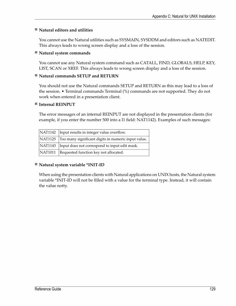
■ Natural editors and utilities
You cannot use theNatural utilities such as SYSMAIN, SYSDDMand editors such as NATEDIT.This always leads to wrong screen display and a loss of the session.
■ Natural system commands
You cannot use any Natural system command such as CATALL, FIND, GLOBALS, HELP, KEY,LIST, SCAN or XREF. This always leads to wrong screen display and a loss of the session.
■ Natural commands SETUP and RETURN
You should not use the Natural commands SETUP and RETURN as this may lead to a loss ofthe session. • Terminal commands Terminal (%) commands are not supported. They do notwork when entered in a presentation client.
■ Internal REINPUT
The error messages of an internal REINPUT are not displayed in the presentation clients (forexample, if you enter the number 500 into a I1 field: NAT1142). Examples of such messages:
Input results in integer value overflow.NAT1142
Too many significant digits in numeric input value.NAT1125
Input does not correspond to input edit mask.NAT1143
Requested function key not allocated.NAT1011
■ Natural system variable *INIT-ID
Whenusing the presentation clientswithNatural applications onUNIXhosts, theNatural systemvariable *INIT-ID will not be filled with a value for the terminal type. Instead, it will containthe value notty.
129Reference Guide
Appendix C: Natural for UNIX Installation

130

17 Appendix E: SSL Cipher Suites Supported by Natural
Screen Tester
Following is a list of the SSL cipher suites supportedwhen connecting to the host. These are relevantwhen running Oracle's JVM. It is possible to use any JSSE provider, including IBM.
TLS_RSA_WITH_AES_128_CBC_SHA
TLS_RSA_WITH_AES_256_CBC_SHA
TLS_ECDH_ECDSA_WITH_AES_128_CBC_SHA
TLS_ECDH_ECDSA_WITH_AES_256_CBC_SHA
TLS_ECDH_RSA_WITH_AES_128_CBC_SHA
TLS_ECDH_RSA_WITH_AES_256_CBC_SHA
TLS_ECDHE_ECDSA_WITH_AES_128_CBC_SHA
TLS_ECDHE_ECDSA_WITH_AES_256_CBC_SHA
TLS_ECDHE_RSA_WITH_AES_128_CBC_SHA
TLS_ECDHE_RSA_WITH_AES_256_CBC_SHA
TLS_DHE_RSA_WITH_AES_128_CBC_SHA
TLS_DHE_RSA_WITH_AES_256_CBC_SHA
TLS_DHE_DSS_WITH_AES_128_CBC_SHA
TLS_DHE_DSS_WITH_AES_256_CBC_SHA
SSL_RSA_WITH_3DES_EDE_CBC_SHA
131

TLS_ECDH_ECDSA_WITH_3DES_EDE_CBC_SHA
TLS_ECDH_RSA_WITH_3DES_EDE_CBC_SHA
TLS_ECDHE_ECDSA_WITH_3DES_EDE_CBC_SHA
TLS_ECDHE_RSA_WITH_3DES_EDE_CBC_SHA
SSL_DHE_RSA_WITH_3DES_EDE_CBC_SHA
SSL_DHE_DSS_WITH_3DES_EDE_CBC_SHA
SSL_RSA_WITH_DES_CBC_SHA
SSL_DHE_RSA_WITH_DES_CBC_SHA
SSL_DHE_DSS_WITH_DES_CBC_SHA
SSL_RSA_EXPORT_WITH_DES40_CBC_SHA
SSL_DHE_RSA_EXPORT_WITH_DES40_CBC_SHA
SSL_DHE_DSS_EXPORT_WITH_DES40_CBC_SHA
SSL_RSA_WITH_NULL_MD5
SSL_RSA_WITH_NULL_SHA
TLS_ECDH_ECDSA_WITH_NULL_SHA
TLS_ECDH_RSA_WITH_NULL_SHA
TLS_ECDHE_ECDSA_WITH_NULL_SHA
TLS_ECDHE_RSA_WITH_NULL_SHA
TLS_DH_anon_WITH_AES_128_CBC_SHA
TLS_DH_anon_WITH_AES_256_CBC_SHA
SSL_DH_anon_WITH_3DES_EDE_CBC_SHA
SSL_DH_anon_WITH_DES_CBC_SHA
TLS_ECDH_anon_WITH_AES_128_CBC_SHA
TLS_ECDH_anon_WITH_AES_256_CBC_SHA
TLS_ECDH_anon_WITH_3DES_EDE_CBC_SHA
SSL_DH_anon_EXPORT_WITH_DES40_CBC_SHA
Reference Guide132
Appendix E: SSL Cipher Suites Supported by Natural Screen Tester

TLS_ECDH_anon_WITH_NULL_SHA
TLS_KRB5_WITH_3DES_EDE_CBC_SHA
TLS_KRB5_WITH_3DES_EDE_CBC_MD5
TLS_KRB5_WITH_DES_CBC_SHA
TLS_KRB5_WITH_DES_CBC_MD5
TLS_KRB5_EXPORT_WITH_DES_CBC_40_SHA
TLS_KRB5_EXPORT_WITH_DES_CBC_40_MD5
133Reference Guide
Appendix E: SSL Cipher Suites Supported by Natural Screen Tester

134

18 Appendix F: Syntax and Format Reference
■ Regular Expression Syntax .............................................................................................................. 136
135

Regular Expression Syntax
Several transformation patterns allow using Regular Expressions to define the textual pattern wewant to find in the host screen.
General Examples
Search forExpression
Specific text, find only "Just some text"Just some text
Text files, like "Readme.txt".*\.txt
Only "Gray" or "Grey"Gr[ae]y
Only "Color" or "Colour"Colou?r
A number between 100 and 99999\b[1-9][0-9]{2,4}\b
Email address, like "[email protected]"\b[A-Z0-9._%-]+@ [A-Z0-9.-]+\.[A-Z]{2,4}\b
Host Specific Examples
ExpressionUse...Search for
[1-9] more >To convert the text "1 more >" or "2 more >" etc. to a buttonthat sends PF11
"1 more >" or "2 more >"
\(.*-.*\)To erase any text with this pattern"(x-y)", "(January-march)", etc.
General Rules
■ [|] separates alternatives.■ Expressions within parentheses are matched as subpattern groups and saved for further use.■ By default, a quantified subpattern matches as many times as possible without causing the restof the pattern not to match. To change the quantifiers to match the minimum number of timespossible, without causing the rest of the pattern not to match, use a [?] right after the quantifier.
Reference Guide136
Appendix F: Syntax and Format Reference

Regular Expression Matching
MatchesExpression
At least n but not more than m times{n,m}
At least n times{n,}
Exactly n times{n}
0 or more times*
1 or more times+
0 or 1 time?
Everything except \n in a regular expression within parentheses.
A null token matching the beginning of a string or line (i.e., the position right after a newline or right before the beginning of a string) in a regular expression within parentheses
^
A null token matching the end of a string or line (that is, the position right before a new lineor right after the end of a string) in a regular expression within parentheses
$
Backspace inside a character class ([abcd])\b
Null token matching a word boundary (\w on one side and \W on the other)\b
Null token matching a boundary that isn't a word boundary\B
Only at the beginning of a string\A
Only at the end of a string (or before a new line at the end)\Z
New line\
Carriage return\r
Tab\t
Form feed\f
Digit [0-9]\d
Non-digit [^0-9]\D
Word character [0-9a-z_A-Z]\w
Non-word character [^0-9a-z_A-Z]\W
A white space character [ \t\n\r\f]\s
A non-white space character [^ \t\n\r\f]\S
The hexadecimal representation of character nn\xnn
The corresponding control character\cD
The octal representation of character nn unless a back reference.\nn or \nnn
Whatever the first, second, third, and so on, parenthesized group matched. This is called aback reference. If there is no corresponding group, the number is interpreted as an octalrepresentation of a character.
\1, \2, \3 ...
The null character. Any other back-slashed character matches itself.\0
0 or more times*?
1 or more times+?
137Reference Guide
Appendix F: Syntax and Format Reference

MatchesExpression
0 or 1 time??
Exactly n times{n}?
At least n times{n,}?
At least n but not more than m times{n,m}?
Reference Guide138
Appendix F: Syntax and Format Reference

19 Appendix G: ASCII Character Table
ValueBinaryHexOctalDecimal
(Null char.)NUL00000000000000000
(Start of Header)SOH00000001001001001
(Start of Text)STX00000010002002002
(End of Text)ETX00000011003003003
(End of Transmission)EOT00000100004004004
(Enquiry)ENQ00000101005005005
(Acknowledgment)ACK00000110006006006
(Bell)BEL00000111007007007
(Backspace)BS00001000008010008
(Horizontal Tab)HT00001001009011009
(Line Feed)LF0000101000A012010
(Vertical Tab)VT0000101100B013011
(Form Feed)FF0000110000C014012
(Carriage Return)CR0000110100D015013
(Shift Out)SO0000111000E016014
(Shift In)SI0000111100F017015
(Data Link Escape)DLE00010000010020016
(Device Control 1)DC1 (XON)00010001011021017
(Device Control 2)DC200010010012022018
(Device Control 3)DC3 (XOFF)00010011013023019
(Device Control 4)DC400010100014024020
(Negative Acknowledgment)NAK00010101015025021
(Synchronous Idle)SYN00010110016026022
(End of Trans. Block)ETB00010111017027023
139

ValueBinaryHexOctalDecimal
(Cancel)CAN00011000018030024
(End of Medium)EM00011001019031025
(Substitute)SUB0001101001A032026
(Escape)ESC0001101101B033027
(File Separator)FS0001110001C034028
(Group Separator)GS0001110101D035029
(Request to Send)(Record Separator)RS0001111001E036030
(Unit Separator)US0001111101F037031
(Space)SP00100000020040032
(exclamation mark)!00100001021041033
(double quote)"00100010022042034
(number sign)#00100011023043035
(dollar sign)$00100100024044036
(percent)%00100101025045037
(ampersand)&00100110026046038
(single quote)'00100111027047039
(left/opening parenthesis)(00101000028050040
(right/closing parenthesis))00101001029051041
(asterisk)*0010101002A052042
(plus)+0010101102B053043
(comma),0010110002C054044
(minus or dash)-0010110102D055045
(dot).0010111002E056046
(forward slash)/0010111102F057047
000110000030060048
100110001031061049
200110010032062050
300110011033063051
400110100034064052
500110101035065053
600110110036066054
700110111037067055
800111000038070056
900111001039071057
(colon):0011101003A072058
(semi-colon);0011101103B073059
Reference Guide140
Appendix G: ASCII Character Table

ValueBinaryHexOctalDecimal
(less than)<0011110003C074060
(equal sign)=0011110103D075061
(greater than)>0011111003E076062
(question mark)?0011111103F077063
(AT symbol)@01000000040100064
A01000001041101065
B01000010042102066
C01000011043103067
D01000100044104068
E01000101045105069
F01000110046106070
G01000111047107071
H01001000048110072
I01001001049111073
J0100101004A112074
K0100101104B113075
L0100110004C114076
M0100110104D115077
N0100111004E116078
O0100111104F117079
P01010000050120080
Q01010001051121081
R01010010052122082
S01010011053123083
T01010100054124084
U01010101055125085
V01010110056126086
W01010111057127087
X01011000058130088
Y01011001059131089
Z0101101005A132090
(left/opening bracket)[0101101105B133091
(back slash)\0101110005C134092
(right/closing bracket)]0101110105D135093
(caret/cirumflex)^0101111005E136094
(underscore)_0101111105F137095
141Reference Guide
Appendix G: ASCII Character Table

ValueBinaryHexOctalDecimal
`01100000060140096
a01100001061141097
b01100010062142098
c01100011063143099
d01100100064144100
e01100101065145101
f01100110066146102
g01100111067147103
h01101000068150104
I01101001069151105
j0110101006A152106
k0110101106B153107
l0110110006C154108
m0110110106D155109
n0110111006E156110
o0110111106F157111
p01110000070160112
q01110001071161113
r01110010072162114
s01110011073163115
t01110100074164116
u01110101075165117
v01110110076166118
w01110111077167119
x01111000078170120
y01111001079171121
z0111101007A172122
(left/opening brace){0111101107B173123
(vertical bar)|0111110007C174124
(right/closing brace)}0111110107D175125
(tilde)~0111111007E176126
(delete)DEL0111111107F177127
Reference Guide142
Appendix G: ASCII Character Table

20 Appendix H: SDFX File Format Definition
■ Introduction .................................................................................................................................. 144■ Mapset File Structure ..................................................................................................................... 144■ Defining Maps ............................................................................................................................... 145■ Defining Identifiers ......................................................................................................................... 146■ Defining Fields .............................................................................................................................. 148■ Defining Map Steps ........................................................................................................................ 152■ Example of an SDFX File ................................................................................................................ 154
143

Introduction
SDFX (Screen Definition Format) is a proprietary generic format used for describing a host screen.In addition to standard formats like BMS, MFS andNatural maps, Natural Screen Tester supportsthis generic format. If your host screen maps are not supported in Natural Screen Tester you canconvert them to the SDFX format and then import them into yourNatural Screen Tester repository.
SDFX is based on the XML structure. Each SDFX file is composed of one mapset, and must havethe ".SDFX" extension.Amapset contains one ormore smaller units calledmaps. Eachmap currentlycorresponds to one host screen. A map is made up of identifiers, fields, and map steps. Mapsets,maps, and fields are identified by name. Natural Screen Tester uses the map name to create ascreen entity with the same name.
Mapset File Structure
The following details the mapset file structure, where all the map and field details are placedwithin the Map tag and are detailed in Defining Maps andDefining Fields.
<Mapset><Name>mapsetname</Name><Version>1</Version><Type>SIMPLE</Type><Map>
...<Map><Map>
...<Map>
<Mapset>
Mapset Parameters
<Name>mapsetname</Name>The name of the mapset (mandatory).
<Version>1</Version>This line contains the SDFX format version (currently, always 1).
<Type>SIMPLE</Type>This line contains the type of SDFX used. Currently the only type available is "SIMPLE".
<Map> ... <Map>Refer toDefining Maps. A number of maps can be added to the same file.
Reference Guide144
Appendix H: SDFX File Format Definition

Defining Maps
Each map represents a single screen and contains the screen properties such as the screen name,screen position, screen width and height etc.
<Map><Name>MapName</Name><PosX>1</PosX><PosY>1</PosY><Width>80</Width><Height>24</Height><IsPopup>false</IsPopup><Field class="SimpleField">...
</Field><Field class="ListField">...
</Field><LoopField>...
</LoopField></Map>
Map Parameters
<Name>MapName</Name>The name of the map (mandatory).
<PosX>1</PosX>The map's horizontal position (the X coordinate of the rectangle's top-left character, can befrom 1 to the width of the screen). When not specified, the default is 1.
<PosY>1</PosY>The map's vertical position (the Y coordinate of the rectangle's top-left character, can be from1 to the height of the screen). When not specified, the default is 1.
<Width>80</Width>The map's width (optional, default is 80).
<Height>24</Height>The map's height (optional, default is 24).
<IsPopup>false</IsPopup>True indicates that this map is used as a pop-up on the host (optional, default is false).
<Field class="SimpleField"> ... </Field>Refer toDefining Fields. A number of fields can be added to the same map.
145Reference Guide
Appendix H: SDFX File Format Definition

Defining Identifiers
Use SDFX identifiers to create Natural Screen Tester identifiers (refer to Defining Identifiers).
Parameters to use for a Text identifier
The identifier is recognized if its textmatches (or does notmatch) the host screen text in the definedposition.
TextThe string to try and match.
IsMatchBoolean (true \ false), default value is true. When set to false, then the identifier is recognizedonly if the host screen's text \ attribute in that position does not match the identifier's text \attribute.
IsCaseSensitiveBoolean (true \ false). When set to true, then the text will be case sensitive.
ScreenAreaRepresents the screen area within in which to search for the identifier. Possible values:
AnywhereAny position on the screen is a valid position.
For example
<ScreenArea class="Anywhere"/>
PositionDefines a position on the screen. StartPos determines the first position within the screen.
For example:
<ScreenArea class="Position"><StartPos>
<PosX>40</PosX><PosY>23</PosY>
</StartPos></ScreenArea>
PositionLengthDefines the first position within the screen and the length of the area.
For example:
Reference Guide146
Appendix H: SDFX File Format Definition

<ScreenArea class="PositionLength"><StartPos><PosX>40</PosX><PosY>23</PosY>
</StartPos><Length>15</Length>
</ScreenArea>
RectangleDefines a rectangle on the screen. StartPos determines the top left position and EndPosdetermines the bottom right position. Together these create a rectangle.
For example:
<ScreenArea class="Rectangle"><StartPos><PosX>10</PosX><PosY>1</PosY>
</StartPos><EndPos><PosX>30</PosX><PosY>24</PosY>
</EndPos></ScreenArea>
The following example is sample code used for a text identifier, using the type "Anywhere".
<Identifier class="Text"><Text>TextToMatch</Text><IsMatch>true</IsMatch><IsCaseSensitive>true</IsCaseSensitive><ScreenArea class="Anywhere"/>
</Identifier>
Parameters to use for an Attribute identifier
The identifier is recognized if its attribute matches the attribute that applies for the host screen inthe defined position. The position does not necessarily has to be the position of the attributecharacter.
AttributeThe attribute to search for. Possible values: PROTECTED, HIDDEN, INTENSIFIED, and RE-VERSED_VIDEO.
ScreenArea: PositionDefines a position on the screen where the attribute should be checked.
For example:
147Reference Guide
Appendix H: SDFX File Format Definition

<ScreenArea class="Position"><StartPos>
<PosX>40</PosX><PosY>23</PosY>
</StartPos></ScreenArea>
The following example is sample code used for an attribute identifier (defines an "Unprotected"attribute).
<Identifier class="Attribute"><Attribute>PROTECTED</Attribute><IsMatch>false</IsMatch><ScreenArea class="Position">
<StartPos><PosX>40</PosX><PosY>23</PosY>
</StartPos></ScreenArea>
</Identifier>
Defining Fields
■ Definitions of a Simple Field: Simple fields can be protected, unprotected or static fields.■ Definitions of a List Field: A List Field is a field which contains a repetitive pattern of simplefields (a "table" of similar cells).
■ Definition of a Loop Field: A loop field describes a repetitive element of the host screen, whichis not a list.
Definitions of a Simple Field
A simple field may be a protected, unprotected or status field. A field for which no name is given,will be considered by Natural Screen Tester to be an identifier. A simple field can also be used asa static identifier.
<Field class="SimpleField"><Type>SIMPLE</Type><Name>DFHM001</Name><PosX>2</PosX><PosY>1</PosY><Length>4</Length><Text>string</Text><Attribute>PROTECTED</Attribute><DataType>DATA_TYPE_ALPHANUMERIC</DataType><Bright>NORM</Bright><ForegroundColor>WHITE</ForegroundColor>
Reference Guide148
Appendix H: SDFX File Format Definition
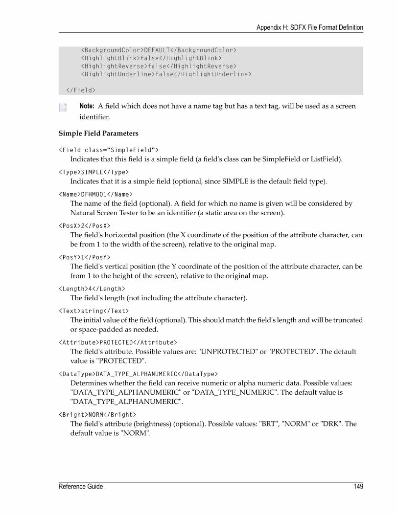
<BackgroundColor>DEFAULT</BackgroundColor><HighlightBlink>false</HighlightBlink><HighlightReverse>false</HighlightReverse><HighlightUnderline>false</HighlightUnderline>
</Field>
Note: A field which does not have a name tag but has a text tag, will be used as a screenidentifier.
Simple Field Parameters
<Field class="SimpleField">Indicates that this field is a simple field (a field's class can be SimpleField or ListField).
<Type>SIMPLE</Type>Indicates that it is a simple field (optional, since SIMPLE is the default field type).
<Name>DFHM001</Name>The name of the field (optional). A field for which no name is given will be considered byNatural Screen Tester to be an identifier (a static area on the screen).
<PosX>2</PosX>The field's horizontal position (the X coordinate of the position of the attribute character, canbe from 1 to the width of the screen), relative to the original map.
<PosY>1</PosY>The field's vertical position (the Y coordinate of the position of the attribute character, can befrom 1 to the height of the screen), relative to the original map.
<Length>4</Length>The field's length (not including the attribute character).
<Text>string</Text>The initial value of the field (optional). This shouldmatch the field's length andwill be truncatedor space-padded as needed.
<Attribute>PROTECTED</Attribute>The field's attribute. Possible values are: "UNPROTECTED" or "PROTECTED". The defaultvalue is "PROTECTED".
<DataType>DATA_TYPE_ALPHANUMERIC</DataType>Determines whether the field can receive numeric or alpha numeric data. Possible values:"DATA_TYPE_ALPHANUMERIC" or "DATA_TYPE_NUMERIC". The default value is"DATA_TYPE_ALPHANUMERIC".
<Bright>NORM</Bright>The field's attribute (brightness) (optional). Possible values: "BRT", "NORM" or "DRK". Thedefault value is "NORM".
149Reference Guide
Appendix H: SDFX File Format Definition

<ForegroundColor>WHITE</ForegroundColor>Indicates the foreground color of the field (optional). The default color is white. The colormustbewritten in capital letters. Possible values include:WHITE, BLACK,AQUA, BLUE, BROWN,GRAY, GREEN, LIGHT_AQUA, LIGHT_BLUE, LIGHT_GREEN, LIGHT_PURPLE,LIGHT_RED, LIGHT_WHITE, PURPLE, RED, YELLOW, NONE, DEFAULT.
<BackgroundColor>DEFAULT</BackgroundColor>Indicates the foreground color of the field (optional). The default color is black. The colormustbe written in capital letters. Possible values include: WHITE, BLACK, AQUA, BLUE,BROWN_YELLOW, GREEN, PURPLE, RED, NONE, DEFAULT.
<HighlightBlink>false</HighlightBlink>BLINK highlighting (optional, default is false).
<HighlightReverse>false</HighlightReverse>REVERSE highlighting (optional, default is false).
<HighlightUnderline>false</HighlightUnderline>UNDERLINE highlighting (optional, default is false).
Definitions of a List Field
A List Field is a field which contains a repetitive pattern of simple fields. Since this repetition canexpand vertically to the right (not only downward), a list can be seen as a "table" of similar cells(Natural Screen Tester multiple fields \ tables). Each cell in the list is called a record and cancontain several fields. You are required to define the first record (cell) and it must consist of Simplefields only.
<Field class="ListField"><Type>LIST</Type><Name>DFHM002</Name><PosX>1</PosX><PosY>1</PosY><Direction>HORIZONTAL_FIRST</Direction><RecordWidth>1</RecordWidth><RecordHeight>1</RecordHeight><RecordsNum>4</RecordsNum><Field>...
</Field><Field>...
</Field></Field>
List Field Parameters
<Field class="ListField">Indicates that this field is a list field (a field's class can be SimpleField or ListField).
Reference Guide150
Appendix H: SDFX File Format Definition

<Type>LIST</Type>Indicates that it is a list field.
<Name>DFHM002</Name>The name of the list (optional).
<PosX>1</PosX>The list's horizontal position (the X coordinate of its top-left corner, can be from 1 to the widthof the screen). Note that the corner of the list's area isn't necessarily the corner of the top-leftcell (unless the cell's position is 1,1).
<PosY>1</PosY>The list's vertical position (the Y coordinate of its top-left corner, can be from 1 to the heightof the screen).
<Direction>HORIZONTAL_FIRST</Direction>The direction in which records are inserted into the list (optional). Possible values are: "VER-TICAL_FIRST" or "HORIZONTAL_FIRST" (default: VERTICAL_FIRST).
<RecordWidth>1</RecordWidth>The width (in characters) of a single list record (i.e. cell). The default value is "1". For example,when wanting to repeat an occurrence every twenty characters (counting from the beginningof the previous record), enter 20 for this parameter and 0 for the value of the RecordHeight.
<RecordHeight>1</RecordHeight>;The height (in characters) of a single list record (i.e. cell). Possible values can be in the range1-99. The default value is "1". For example, when wanting to repeat an occurrence every tworows (counting from the first row of the previous occurrence), enter 2 for this parameter.
<RecordsNum>4</RecordsNum>The total number of records to produce. Possible values can be in the range 1-99. The defaultvalue is "1".
Definition of a Loop Field
A loop field describes a repetitive element of the host screen, which is not a list. Themost commonexample being the drawing of a frame of some sortwhich consists of simple (static) fields one belowthe other. Each simple field inside the loop field is repeated (cloned) either along the x-axis, y-axisor both ("table"). The distance between adjacent cloned fields is controllable, and it is the user'sresponsibility to make sure cloned fields are kept within the map's bounds.
<LoopField><HorizontalClonesNum>1</HorizontalClonesNum><HorizontalOffset>1</HorizontalOffset><VerticalClonesNum>1</VerticalClonesNum><VerticalOffset>1</VerticalOffset><Field>
...</Field><Field>
151Reference Guide
Appendix H: SDFX File Format Definition

...</Field>
</LoopField>
Loop Field Parameters
<HorizontalClonesNum>1</HorizontalClonesNum>The number of cloned fields (including the field itself) to be created in each row (optional,default is 1).
<HorizontalOffset>1</HorizontalOffset>The number of columns between adjacent cloned fields (optional, default is 1 which meansthat there are no blank columns between cloned fields, just attributes).
<VerticalClonesNum>1</VerticalClonesNum>The number of cloned fields (including the field itself) to be created in each column (optional,default is 1).
<VerticalOffset>1</VerticalOffset>The number of rows between adjacent cloned fields (optional, default is 1 which means thatthere are no blank rows between cloned fields).
Defining Map Steps
The Map Steps defined here can be used in the Test Project Map.
<MapStep><SendKeys>[ENTER]</SendKeys><TargetScreen>ScreenName</TargetScreen><CursorPos>
<PosX>10</PosX><PosY>5</PosY>
</CursorPos><InputField>
<StartPos><PosX>10</PosX><PosY>5</PosY>
</StartPos><Text>input</Text>
</InputField><InputField>
<StartPos><PosX>10</PosX><PosY>7</PosY>
</StartPos><GlobalVariableName>variableName</GlobalVariableName><Text>prefix</Text>
</InputField><InputField>
Reference Guide152
Appendix H: SDFX File Format Definition
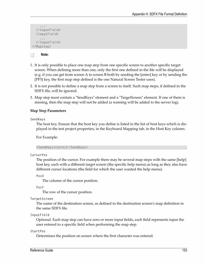
...</InputField><InputField>
...</InputField>
</Mapstep>
Note:
1. It is only possible to place one map step from one specific screen to another specific targetscreen. When defining more than one, only the first one defined in the file will be displayed(e.g. if you can get from screen A to screen B both by sending the [enter] key or by sending the[PF5] key, the first map step defined is the one Natural Screen Tester uses).
2. It is not possible to define a map step from a screen to itself. Such map steps, if defined in theSDFX file, will be ignored.
3. Map step must contain a "SendKeys" element and a "TargetScreen" element. If one of them ismissing, then the map step will not be added (a warning will be added to the server log).
Map Step Parameters
SendKeysThe host key. Ensure that the host key you define is listed in the list of host keys which is dis-played in the test project properties, in the Keyboard Mapping tab, in the Host Key column.
For Example:
<SendKeys>[attn]</SendKeys>
CursorPosThe position of the cursor. For example there may be several map steps with the same [help]host key, each with a different target screen (the specific help menu) as long as they also havedifferent cursor locations (the field for which the user wanted the help menu).
PosXThe column of the cursor position.
PosYThe row of the cursor position.
TargetScreenThe name of the destination screen, as defined in the destination screen's map definition inthe same SDFX file.
InputFieldOptional. Each map step can have zero or more input fields, each field represents input theuser entered to a specific field when performing the map step.
StartPosDetermines the position on screen where the first character was entered.
153Reference Guide
Appendix H: SDFX File Format Definition

PosXThe column of the cursor position.
PosYThe row of the cursor position.
GlobalVariableNameOptional. The name of the global variable whose value should be used as the text.
TextThe text entered.
Example of an SDFX File
<Mapset><Name>Example</Name><Version>1</Version><Type>SIMPLE</Type><Map>
<Name>Example</Name><PosX>1</PosX><PosY>1</PosY><Width>80</Width><Height>24</Height><CursorPosX>1</CursorPosX><CursorPosY>1</CursorPosY><IsPopup>false</IsPopup>
<Field class="SimpleField"><Length>10</Length><Attribute>PROTECTED</Attribute><DataType>DATA_TYPE_ALPHANUMERIC</DataType><Bright>NORM</Bright><ForegroundColor>GREEN</ForegroundColor><BackgroundColor>DEFAULT</BackgroundColor><DbcsMode>NONE</DbcsMode><HighlightBlink>false</HighlightBlink><HighlightReverse>false</HighlightReverse><HighlightUnderline>false</HighlightUnderline><OffsetFromLeft>0</OffsetFromLeft><OffsetFromRight>0</OffsetFromRight><OffsetFromTop>0</OffsetFromTop><OffsetFromBottom>0</OffsetFromBottom><Type>SIMPLE</Type>
<Text>First Name</Text><PosX>8</PosX><PosY>3</PosY>
</Field><Field class="SimpleField">
<Length>10</Length>
Reference Guide154
Appendix H: SDFX File Format Definition

<Attribute>PROTECTED</Attribute><DataType>DATA_TYPE_ALPHANUMERIC</DataType><Bright>NORM</Bright><ForegroundColor>WHITE</ForegroundColor><BackgroundColor>DEFAULT</BackgroundColor><Type>SIMPLE</Type>
<Text>----------</Text><PosX>8</PosX><PosY>4</PosY>
</Field><Field class="SimpleField">
<Length>10</Length><Attribute>PROTECTED</Attribute><DataType>DATA_TYPE_ALPHANUMERIC</DataType><Bright>NORM</Bright><ForegroundColor>WHITE</ForegroundColor><BackgroundColor>DEFAULT</BackgroundColor><OffsetFromLeft>0</OffsetFromLeft><OffsetFromRight>0</OffsetFromRight><OffsetFromTop>0</OffsetFromTop><OffsetFromBottom>0</OffsetFromBottom><Type>SIMPLE</Type>
<Text>----------</Text><PosX>20</PosX><PosY>4</PosY>
</Field><Field class="SimpleField">
<Length>10</Length><Attribute>PROTECTED</Attribute><DataType>DATA_TYPE_ALPHANUMERIC</DataType><Bright>NORM</Bright><ForegroundColor>BLUE</ForegroundColor><BackgroundColor>DEFAULT</BackgroundColor><DbcsMode>NONE</DbcsMode><HighlightBlink>false</HighlightBlink><HighlightReverse>false</HighlightReverse><HighlightUnderline>false</HighlightUnderline><OffsetFromLeft>0</OffsetFromLeft><OffsetFromRight>0</OffsetFromRight><OffsetFromTop>0</OffsetFromTop><OffsetFromBottom>0</OffsetFromBottom><Type>SIMPLE</Type>
<Text>Last Name</Text><PosX>20</PosX><PosY>3</PosY>
</Field><Field class="ListField"><Direction>HORIZONTAL_FIRST</Direction><RecordWidth>1</RecordWidth><RecordHeight>1</RecordHeight><RecordsNum>15</RecordsNum><Field>
155Reference Guide
Appendix H: SDFX File Format Definition

<Name>firstName</Name><Length>10</Length><Attribute>PROTECTED</Attribute><DataType>DATA_TYPE_ALPHANUMERIC</DataType><Bright>BRT</Bright><DbcsMode>NONE</DbcsMode><Type>SIMPLE</Type><PosX>8</PosX><PosY>6</PosY>
</Field><Field><Name>lastName</Name>
<Length>10</Length><Attribute>UNPROTECTED</Attribute><DataType>DATA_TYPE_NUMERIC</DataType><Bright>NORM</Bright><ForegroundColor>WHITE</ForegroundColor><BackgroundColor>DEFAULT</BackgroundColor><Type>SIMPLE</Type><PosX>20</PosX><PosY>6</PosY>
</Field><Type>LIST</Type><PosX>1</PosX><PosY>1</PosY>
</Field><LoopField><HorizontalClonesNum>1</HorizontalClonesNum><HorizontalOffset>1</HorizontalOffset><VerticalClonesNum>1</VerticalClonesNum><VerticalOffset>1</VerticalOffset>
</LoopField></Map>
</Mapset>
Reference Guide156
Appendix H: SDFX File Format Definition

21 Appendix I: Dynamic Field Mapping Limitations
In some screens, the position of a field may vary. It is therefore necessary to map some fields insuch a way, that even if they appear in a different position, they will still be recognized andmapped. This is possible by defining the label near the field (the label must be to the left of thefield) and identifying the field according to this label. Thismapping type is called "SingleDynamic"as the mapping position changes dynamically according to the leading label. Refer to Map Fieldssection for further details as to how to map test project fields according to their leading label.
Following are some limitations:
There is no specific identifier on the host screen which distinguishes between protected fields andstatic text which cannot change in runtime. This implies the following limitations:
■ If a field does not have a distinctive label exactly to its left, it cannot be defined as a dynamicfield.
■ This feature is disabled for test projects that are defined with a right to left language (a newdynamic field mapping can't be created).
■ Static and Dynamic field mappings should not be set to match the same fields.
Specific use cases
■ When the protected field is blank, any text to the right of the field is matched as the protectedfield area.
157

■ When a label andfield are separated by a singlewhite space, the protected fieldwon't bematched,unless the "field search area" and "label search area" do not overlap.
■ When arbitrary text in a protected field, matches the label search criteria it is wrongly matchedas a field label, and the text to the right of it may be wrongly marked as a protected field.
■ When the text of the protected field starts with white spaces or separator characters, such as adot or colon this text won't be considered as part of the field.
■ If two white spaces or separator characters appear as a sequence inside a protected field, theywill be considered as a field boundary. For example, a rowpart containing the text "Hello, world"will be identified as a protected fieldwith the text "Hello" only. In addition, when a leading labelis defined as a part of a protected field's actual label and the actual label contains two or moreseparator characters (after the given leading label), the rest of the actual label might be falselymarked as the protected field. Note that these limitations are data-dependent, they may onlysurface when specific data is sent from the host and therefore may not be identified duringdesgin time but only in runtime.
Note: See alsoMappingMultiple Dynamic Fieldsunder Screens in theDesigning andDevelopinga Test Case documentation.
Reference Guide158
Appendix I: Dynamic Field Mapping Limitations
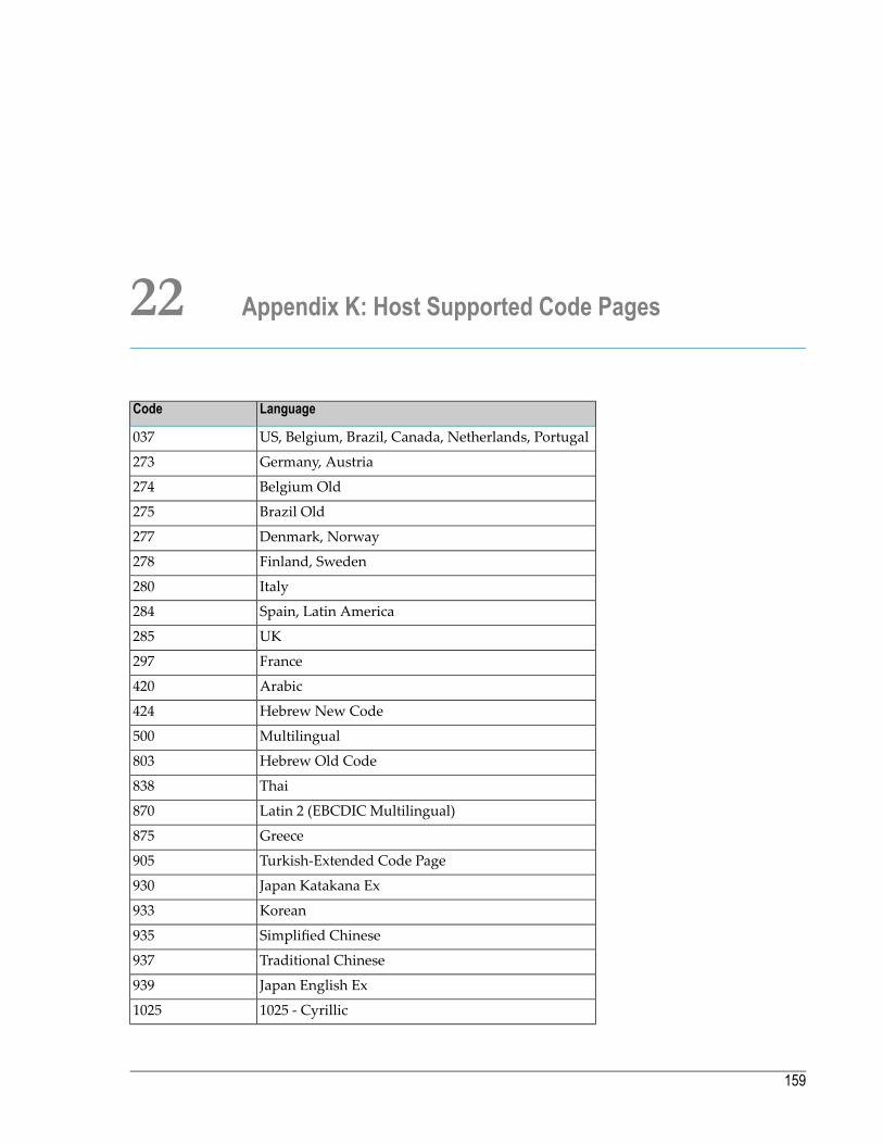
22 Appendix K: Host Supported Code Pages
LanguageCode
US, Belgium, Brazil, Canada, Netherlands, Portugal037
Germany, Austria273
Belgium Old274
Brazil Old275
Denmark, Norway277
Finland, Sweden278
Italy280
Spain, Latin America284
UK285
France297
Arabic420
Hebrew New Code424
Multilingual500
Hebrew Old Code803
Thai838
Latin 2 (EBCDIC Multilingual)870
Greece875
Turkish-Extended Code Page905
Japan Katakana Ex930
Korean933
Simplified Chinese935
Traditional Chinese937
Japan English Ex939
1025 - Cyrillic1025
159

LanguageCode
Turkish1026
Vietnamese1130
Turkish - Euro support1155
Farsi1097
Multilingual Swiss1500
VT configurations
Japanese SJISSJIS
Japanese EUCEUC
Thai874
Hebrew916
Japanese ISO932
German1011
Portuguese1024
Decimal Special Graphics1090
Multi1100
Hebrew 7-bit1134
Line Drawing3000
International4001
Multilingual4002
Session 3151 Initial4040
Session 31514041
ANSI Special Graphics4090
ISO-8859-18000
Reference Guide160
Appendix K: Host Supported Code Pages
Related Documents


