Natural Programming Guide Version 6.3.13 for Windows October 2012

Welcome message from author
This document is posted to help you gain knowledge. Please leave a comment to let me know what you think about it! Share it to your friends and learn new things together.
Transcript

Natural
Programming Guide
Version 6.3.13 for Windows
October 2012

This document applies to Natural Version 6.3.13 for Windows.
Specifications contained herein are subject to change and these changes will be reported in subsequent release notes or new editions.
Copyright © 1992-2012 Software AG, Darmstadt, Germany and/or Software AG USA, Inc., Reston, VA, United States of America,and/or their licensors.
Detailed information on trademarks and patents owned by Software AG and/or its subsidiaries is located athttp://documentation.softwareag.com/legal/.
Use of this software is subject to adherence to Software AG's licensing conditions and terms. These terms are part of the product doc-umentation, located at http://documentation.softwareag.com/legal/ and/or in the root installation directory of the licensed product(s).
This softwaremay include portions of third-party products. For third-party copyright notices and license terms, please refer to "LicenseTexts, Copyright Notices and Disclaimers of Third-Party Products". This document is part of the product documentation, located athttp://documentation.softwareag.com/legal/ and/or in the root installation directory of the licensed product(s).
Document ID: NATWIN-NNATPROGRAMMING-6313-20121005
Table of Contents
Preface ............................................................................................................................. xxiI Natural Programming Modes .......................................................................................... 1
1 Natural Programming Modes ................................................................................. 3Purpose of Programming Modes ....................................................................... 4Setting/Changing the Programming Mode ....................................................... 5Functional Differences ....................................................................................... 5
II Object Types .................................................................................................................. 112 Using Natural Programming Objects .................................................................... 13
Types of Programming Objects ........................................................................ 14Creating and Maintaining Programming Objects ............................................ 14
3 Data Areas ............................................................................................................. 17Use of Data Areas ............................................................................................. 18Local Data Area ................................................................................................ 18Global Data Area .............................................................................................. 19Parameter Data Area ........................................................................................ 28
4 Programs, Functions, Subprograms and Subroutines .......................................... 33A Modular Application Structure .................................................................... 34Multiple Levels of Invoked Objects ................................................................. 34Program ............................................................................................................ 36Function ............................................................................................................ 39Subroutine ........................................................................................................ 41Subprogram ...................................................................................................... 46Processing Flow when Invoking a Routine ...................................................... 48
5 Processing a Rich GUI Page - Adapter .................................................................. 516 Maps ...................................................................................................................... 53
Benefits of Using Maps .................................................................................... 54Types of Maps .................................................................................................. 54Creating Maps .................................................................................................. 55Starting/Stopping Map Processing ................................................................... 55
7 Helproutines .......................................................................................................... 57Invoking Help .................................................................................................. 58Specifying Helproutines ................................................................................... 58Programming Considerations for Helproutines .............................................. 59Passing Parameters to Helproutines ................................................................ 59Equal Sign Option ............................................................................................ 60Array Indices .................................................................................................... 61Help as a Window ............................................................................................ 61
8 Multiple Use of Source Code - Copycode ............................................................. 63Use of Copycode .............................................................................................. 64Processing of Copycode ................................................................................... 64
9 Documenting Natural Objects - Text ..................................................................... 65Use of Text Objects ........................................................................................... 66Writing Text ...................................................................................................... 66
iii

10 Creating Event Driven Applications - Dialog ..................................................... 6711 Creating Component Based Applications - Class ............................................... 6912 Using Non-Natural Files - Resource .................................................................... 71
Use of Resources .............................................................................................. 72Shared Resources ............................................................................................. 72Private Resources ............................................................................................. 73API for Processing Resources ........................................................................... 73
III Defining Fields ............................................................................................................. 7513 Use and Structure of DEFINE DATA Statement ................................................. 77
Field Definitions in DEFINE DATA Statement ................................................ 78Defining Fields within a DEFINE DATA Statement ........................................ 78Defining Fields in a Separate Data Area .......................................................... 79Structuring a DEFINE DATA Statement Using Level Numbers ..................... 79
14 User-Defined Variables ........................................................................................ 83Definition of Variables ...................................................................................... 84Referencing of Database Fields Using (r) Notation ......................................... 85Renumbering of Source-Code Line Number References ................................. 86Format and Length of User-Defined Variables ................................................ 87Special Formats ................................................................................................ 88Index Notation ................................................................................................. 91Referencing a Database Array .......................................................................... 93Referencing the Internal Count for a Database Array (C* Notation) ............. 101Qualifying Data Structures ............................................................................. 104Examples of User-Defined Variables .............................................................. 105
15 Function Call ...................................................................................................... 107Calling User-Defined Functions ..................................................................... 108Function Result ............................................................................................... 109Evaluation Sequence ...................................................................................... 109Restrictions ..................................................................................................... 109Syntax Description ......................................................................................... 110Example .......................................................................................................... 114
16 Introduction to Dynamic Variables and Fields .................................................. 119Purpose of Dynamic Variables ....................................................................... 120Definition of Dynamic Variables .................................................................... 120Value Space Currently Used for a Dynamic Variable .................................... 121Size Limitation Check ..................................................................................... 121Allocating/Freeing Memory Space for a Dynamic Variable .......................... 122
17 Using Dynamic and Large Variables ................................................................. 125General Remarks ............................................................................................ 126Assignments with Dynamic Variables ........................................................... 127Initialization of Dynamic Variables ................................................................ 129String Manipulation with Dynamic Alphanumeric Variables ....................... 129Logical Condition Criterion (LCC) with Dynamic Variables ......................... 130AT/IF-BREAK of Dynamic Control Fields ..................................................... 132Parameter Transfer with Dynamic Variables ................................................. 132
Programming Guideiv
Programming Guide
Work File Access with Large and Dynamic Variables ................................... 135DDM Generation and Editing for Varying Length Columns ........................ 136Accessing Large Database Objects ................................................................. 138Performance Aspects with Dynamic Variables .............................................. 139Outputting Dynamic Variables ...................................................................... 140Dynamic X-Arrays .......................................................................................... 141
18 User-Defined Constants ..................................................................................... 143Numeric Constants ......................................................................................... 144Alphanumeric Constants ............................................................................... 145Unicode Constants ......................................................................................... 146Date and Time Constants ............................................................................... 149Hexadecimal Constants .................................................................................. 150Logical Constants ........................................................................................... 152Floating Point Constants ................................................................................ 152Attribute Constants ........................................................................................ 153Handle Constants ........................................................................................... 154Defining Named Constants ............................................................................ 154
19 Initial Values (and the RESET Statement) .......................................................... 157Default Initial Value of a User-Defined Variable/Array ................................. 158Assigning an Initial Value to a User-Defined Variable/Array ........................ 158Resetting a User-Defined Variable to its Initial Value .................................... 160
20 Redefining Fields ............................................................................................... 163Using the REDEFINE Option of DEFINE DATA ........................................... 164Example Program Illustrating the Use of a Redefinition ............................... 165
21 Arrays ................................................................................................................ 167Defining Arrays .............................................................................................. 168Initial Values for Arrays ................................................................................. 169Assigning Initial Values to One-Dimensional Arrays .................................... 169Assigning Initial Values to Two-Dimensional Arrays .................................... 170A Three-Dimensional Array ........................................................................... 174Arrays as Part of a Larger Data Structure ...................................................... 176Database Arrays ............................................................................................. 177Using Arithmetic Expressions in Index Notation .......................................... 177Arithmetic Support for Arrays ....................................................................... 178
22 X-Arrays ............................................................................................................. 181Definition ........................................................................................................ 182Storage Management of X-Arrays .................................................................. 183Storage Management of X-Group Arrays ...................................................... 183Referencing an X-Array .................................................................................. 185Parameter Transfer with X-Arrays ................................................................. 186Parameter Transfer with X-Group Arrays ...................................................... 187X-Array of Dynamic Variables ....................................................................... 188Lower and Upper Bound of an Array ............................................................ 189
IV User-Defined Functions ............................................................................................. 19123 User-Defined Functions ..................................................................................... 193
vProgramming Guide
Programming Guide
Introduction to User-Defined Functions ........................................................ 194Restrictions ..................................................................................................... 195Function Call versus Subprogram Call .......................................................... 195Function Definition (DEFINE FUNCTION) ................................................... 198Symbolic and Variable Function Call ............................................................. 198Function Result and Parameters .................................................................... 198Explicit Prototype Definition (DEFINE PROTOTYPE) .................................. 199Implicit (Automatic) Prototype Definition ..................................................... 199Prototype Cast (PT Clause) ............................................................................ 200Intermediate Result Definition (IR Clause) .................................................... 200Combinations of Possible Prototype Definitions ........................................... 200Evaluation Sequence of Functions in Statements ........................................... 202Using a Function as a Statement .................................................................... 204
V Accessing Data in a Database ..................................................................................... 20724 Natural and Database Access ............................................................................ 209
Database Management Systems Supported by Natural ................................ 210Profile Parameters Influencing Database Access ........................................... 211Access through Data Definition Modules ...................................................... 211Natural's Data Manipulation Language ........................................................ 212Natural's Special SQL Statements .................................................................. 213
25 Accessing Data in an Adabas Database ............................................................. 215Adabas Database Management Interfaces ADA and ADA2 ......................... 216Data Definition Modules - DDMs .................................................................. 216Database Arrays ............................................................................................. 218Defining a Database View .............................................................................. 224Statements for Database Access ..................................................................... 227Multi-Fetch Clause ......................................................................................... 239Database Processing Loops ............................................................................ 240Database Update - Transaction Processing .................................................... 246Selecting Records Using ACCEPT/REJECT ................................................... 253AT START/END OF DATA Statements .......................................................... 257Unicode Data .................................................................................................. 259
26 Accessing Data in an SQL Database .................................................................. 261Generating Natural DDMs ............................................................................. 262Setting Natural Profile Parameters ................................................................. 262Natural DML Statements ............................................................................... 263Natural SQL Statements ................................................................................. 269Flexible SQL .................................................................................................... 277RDBMS-Specific Requirements and Restrictions ........................................... 278Data-Type Conversion .................................................................................... 281Date/Time Conversion ................................................................................... 281Obtaining Diagnostic Information about Database Errors ............................ 283SQL Authorization ......................................................................................... 283
27 Accessing Data in a Tamino Database ............................................................... 285Prerequisite ..................................................................................................... 286
Programming Guidevi
Programming Guide

DDM and View Definitions with Natural for Tamino ................................... 286Natural Statements for Tamino Database Access .......................................... 290Natural for Tamino Restrictions ..................................................................... 294
VI Controlling Data Output ........................................................................................... 29728 Report Specification - (rep) Notation ................................................................. 299
Use of Report Specifications ........................................................................... 300Statements Concerned .................................................................................... 300Examples of Report Specification ................................................................... 300
29 Layout of an Output Page .................................................................................. 301Statements Influencing a Report Layout ........................................................ 302General Layout Example ................................................................................ 302
30 Statements DISPLAY and WRITE ...................................................................... 305DISPLAY Statement ........................................................................................ 306WRITE Statement ........................................................................................... 307Example of DISPLAY Statement .................................................................... 308Example of WRITE Statement ........................................................................ 308Column Spacing - SF Parameter and nX Notation ......................................... 309Tab Setting - nT Notation ............................................................................... 310Line Advance - Slash Notation ....................................................................... 311Further Examples of DISPLAY and WRITE Statements ................................ 314
31 Index Notation for Multiple-Value Fields and Periodic Groups ....................... 315Use of Index Notation .................................................................................... 316Example of Index Notation in DISPLAY Statement ....................................... 316Example of Index Notation in WRITE Statement .......................................... 317
32 Page Titles, Page Breaks, Blank Lines ................................................................ 319Default Page Title ........................................................................................... 320Suppress Page Title - NOTITLE Option ......................................................... 320Define Your Own Page Title - WRITE TITLE Statement ................................ 321Logical Page and Physical Page ..................................................................... 324Page Size - PS Parameter ................................................................................ 326Page Advance ................................................................................................. 326New Page with Title ....................................................................................... 329Page Trailer - WRITE TRAILER Statement .................................................... 330Generating Blank Lines - SKIP Statement ...................................................... 332AT TOP OF PAGE Statement ......................................................................... 333AT END OF PAGE Statement ......................................................................... 334Further Example ............................................................................................. 336
33 Column Headers ................................................................................................ 337Default Column Headers ............................................................................... 338Suppress Default Column Headers - NOHDR Option .................................. 338Define Your Own Column Headers ............................................................... 339Combining NOTITLE and NOHDR ............................................................... 340Centering of Column Headers - HC Parameter ............................................. 340Width of Column Headers - HW Parameter .................................................. 340Filler Characters for Headers - Parameters FC and GC ................................. 341
viiProgramming Guide
Programming Guide
Underlining Character for Titles and Headers - UC Parameter .................... 342Suppressing Column Headers - Slash Notation ............................................ 343Further Examples of Column Headers .......................................................... 344
34 Parameters to Influence the Output of Fields .................................................... 345Overview of Field-Output-Relevant Parameters ........................................... 346Leading Characters - LC Parameter ............................................................... 346Unicode Leading Characters - LCU Parameter .............................................. 347Insertion Characters - IC Parameter ............................................................... 347Unicode Insertion Characters - ICU Parameter ............................................. 348Trailing Characters - TC Parameter ................................................................ 348Unicode Trailing Characters - TCU Parameter .............................................. 348Output Length - AL and NL Parameters ....................................................... 349Display Length for Output - DL Parameter ................................................... 349Sign Position - SG Parameter .......................................................................... 351Identical Suppress - IS Parameter ................................................................... 353Zero Printing - ZP Parameter ......................................................................... 355Empty Line Suppression - ES Parameter ....................................................... 355Further Examples of Field-Output-Relevant Parameters .............................. 357
35 Code Page Edit Masks - EM Parameter ............................................................. 359Use of EM Parameter ...................................................................................... 360Edit Masks for Numeric Fields ....................................................................... 360Edit Masks for Alphanumeric Fields ............................................................. 361Length of Fields .............................................................................................. 361Edit Masks for Date and Time Fields ............................................................. 362Customizing Separator Character Displays ................................................... 362Examples of Edit Masks ................................................................................. 364Further Examples of Edit Masks .................................................................... 366
36 Unicode Edit Masks - EMU Parameter .............................................................. 36737 Vertical Displays ................................................................................................ 369
Creating Vertical Displays .............................................................................. 370Combining DISPLAY and WRITE .................................................................. 370Tab Notation - T*field ..................................................................................... 371Positioning Notation x/y ................................................................................ 372DISPLAY VERT Statement ............................................................................. 373Further Example of DISPLAY VERT with WRITE Statement ........................ 379
VII Further Programming Aspects ................................................................................. 38138 End of Statement, Program or Application ....................................................... 383
End of Statement ............................................................................................ 384End of Program .............................................................................................. 384End of Application ......................................................................................... 384
39 Processing of Application Errors ....................................................................... 387Natural's Default Error Processing ................................................................ 388Application Specific Error Processing ............................................................ 388Using an ON ERROR Statement Block .......................................................... 389Using an Error Transaction Program ............................................................. 390
Programming Guideviii
Programming Guide

Error Processing Related Features ................................................................. 39340 Conditional Processing - IF Statement .............................................................. 397
Structure of IF Statement ................................................................................ 398Nested IF Statements ...................................................................................... 400
41 Loop Processing ................................................................................................. 403Use of Processing Loops ................................................................................. 404Limiting Database Loops ............................................................................... 404Limiting Non-Database Loops - REPEAT Statement ..................................... 406Example of REPEAT Statement ...................................................................... 407Terminating a Processing Loop - ESCAPE Statement .................................... 408Loops Within Loops ....................................................................................... 408Example of Nested FIND Statements ............................................................. 408Referencing Statements within a Program ..................................................... 409Example of Referencing with Line Numbers ................................................. 411Example with Statement Reference Labels .................................................... 412
42 Control Breaks ................................................................................................... 415Use of Control Breaks ..................................................................................... 416AT BREAK Statement ..................................................................................... 416Automatic Break Processing .......................................................................... 421Example of System Functions with AT BREAK Statement ............................ 422Further Example of AT BREAK Statement .................................................... 424BEFORE BREAK PROCESSING Statement ................................................... 424Example of BEFORE BREAK PROCESSING Statement ................................ 424User-Initiated Break Processing - PERFORM BREAK PROCESSINGStatement ........................................................................................................ 425Example of PERFORM BREAK PROCESSING Statement ............................ 427
43 Data Computation ............................................................................................. 429COMPUTE Statement ..................................................................................... 430Statements MOVE and COMPUTE ................................................................ 431Statements ADD, SUBTRACT, MULTIPLY and DIVIDE ............................... 432Example of MOVE, SUBTRACT and COMPUTE Statements ....................... 432COMPRESS Statement ................................................................................... 433Example of COMPRESS and MOVE Statements ........................................... 434Example of COMPRESS Statement ................................................................ 435Mathematical Functions ................................................................................. 436Further Examples of COMPUTE, MOVE and COMPRESS Statements ........ 437
44 System Variables and System Functions ........................................................... 439System Variables ............................................................................................. 440System Functions ............................................................................................ 441Example of System Variables and System Functions ..................................... 442Further Examples of System Variables ........................................................... 443Further Examples of System Functions .......................................................... 444
45 Stack ................................................................................................................... 445Use of Natural Stack ....................................................................................... 446Stack Processing ............................................................................................. 446
ixProgramming Guide
Programming Guide

Placing Data on the Stack ............................................................................... 447Clearing the Stack ........................................................................................... 448
46 Processing of Date Information ......................................................................... 449Edit Masks for Date Fields and Date System Variables ................................. 450Default Edit Mask for Date - DTFORM Parameter ........................................ 450Date Format for Alphanumeric Representation - DF Parameter ................... 451Date Format for Output - DFOUT Parameter ................................................ 453Date Format for Stack - DFSTACK Parameter ............................................... 454Year Sliding Window - YSLW Parameter ....................................................... 455Combinations of DFSTACK and YSLW ......................................................... 457Year Fixed Window ........................................................................................ 459Date Format for Default Page Title - DFTITLE Parameter ............................. 459
47 Text Notation ..................................................................................................... 461Defining a Text to Be Used with a Statement - the 'text' Notation ................. 462Defining a Character to Be Displayed n Times before a Field Value - the'c'(n) Notation ................................................................................................. 463
48 User Comments ................................................................................................. 465Using an Entire Source Code Line for Comments ......................................... 466Using the Latter Part of a Source Code Line for Comments .......................... 467
49 Logical Condition Criteria ................................................................................. 469Introduction .................................................................................................... 470Relational Expression ..................................................................................... 471Extended Relational Expression ..................................................................... 475Evaluation of a Logical Variable ..................................................................... 476Fields Used within Logical Condition Criteria .............................................. 477Logical Operators in Complex Logical Expressions ...................................... 479BREAK Option - Compare Current Value with Value of Previous LoopPass ................................................................................................................. 480IS Option - Check whether Content of Alphanumeric or Unicode Field canbe Converted .................................................................................................. 482MASK Option - Check Selected Positions of a Field for Specific Content ..... 484MASK Option Compared with IS Option ...................................................... 491MODIFIED Option - Check whether Field Content has been Modified ....... 493SCAN Option - Scan for a Value within a Field ............................................. 494SPECIFIED Option - Check whether a Value is Passed for an OptionalParameter ........................................................................................................ 496
50 Rules for Arithmetic Assignment ...................................................................... 499Field Initialization .......................................................................................... 500Data Transfer .................................................................................................. 500Field Truncation and Field Rounding ............................................................ 503Result Format and Length in Arithmetic Operations .................................... 503Arithmetic Operations with Floating-Point Numbers ................................... 504Arithmetic Operations with Date and Time .................................................. 506Performance Considerations for Mixed Format Expressions ........................ 510Precision of Results of Arithmetic Operations ............................................... 510
Programming Guidex
Programming Guide

Error Conditions in Arithmetic Operations ................................................... 511Processing of Arrays ....................................................................................... 512
51 Invoking Natural Subprograms from 3GL Programs ....................................... 519Passing Parameters from the 3GL Program to the Subprogram .................... 520Example of Invoking a Natural Subprogram from a 3GL Program .............. 521
52 Issuing Operating System Commands from within a Natural Program .......... 523Syntax ............................................................................................................. 524Parameters ...................................................................................................... 524Parameter Options .......................................................................................... 524Return Codes .................................................................................................. 525Examples ........................................................................................................ 525
53 Statements for Internet and XML Access .......................................................... 527Statements Available ...................................................................................... 528Further References .......................................................................................... 529
VIII Portable Natural Generated Programs ................................................................... 53154 Portable Natural Generated Programs .............................................................. 533
Compatibility .................................................................................................. 534Endian Mode Considerations ......................................................................... 534ENDIAN Parameter ....................................................................................... 535Transferring Natural Generated Programs .................................................... 535Portable FILEDIR.SAG and Error Message Files ........................................... 537
IX Introduction to Event-Driven Programming ............................................................. 53955 What is an Event-Driven Application? .............................................................. 541
Introduction .................................................................................................... 542Program-Driven Applications ........................................................................ 543Event Driven Applications ............................................................................. 544What is Happening Here? .............................................................................. 545Writing Event-Driven Code ............................................................................ 545Components of an Event Driven Application ................................................ 546
56 GUI Development Environments ...................................................................... 54957 GUI Design Tips ................................................................................................ 551
Introduction .................................................................................................... 552Do Your Research ........................................................................................... 552Screen Design ................................................................................................. 553Menu Design .................................................................................................. 554Color Usage .................................................................................................... 555Consistency Check ......................................................................................... 555
58 Tasks Involved in Creating an Application ....................................................... 55759 Tutorial ............................................................................................................... 559
Creating a Dialog ............................................................................................ 560Assigning Attributes to the Dialog ................................................................ 561Creating Dialog Elements Inside the Dialog .................................................. 563Assigning Attributes to the Dialog Elements ................................................. 565Creating the Application's Local Data Area ................................................... 566Attaching Event Handler Code to the Dialog Element .................................. 567
xiProgramming Guide
Programming Guide

Checking, Stowing and Running the Application ......................................... 56860 Basic Terminology .............................................................................................. 569
Attribute ......................................................................................................... 570Base Dialog ..................................................................................................... 570Control ............................................................................................................ 571Dialog ............................................................................................................. 571Dialog Box ...................................................................................................... 571Dialog Editor .................................................................................................. 571Dialog Element ............................................................................................... 571Event ............................................................................................................... 572Event Handler ................................................................................................ 572Handle ............................................................................................................ 572Item ................................................................................................................. 572MDI - Multiple Document Interface ............................................................... 572MDI Child Window ........................................................................................ 573MDI Frame Window ...................................................................................... 573Modal Window ............................................................................................... 573SDI - Single Document Interface .................................................................... 573Popup ............................................................................................................. 573Window .......................................................................................................... 573
X Event-Driven Programming Techniques .................................................................... 57561 Introduction ....................................................................................................... 57762 How To Open and Close Dialogs ...................................................................... 579
Opening a Dialog ........................................................................................... 580Operands ........................................................................................................ 580Passing Parameters to the Dialog ................................................................... 581Permanence in Creating, Passing and Checking Data ................................... 582Processing Steps When Opening a Dialog ..................................................... 583Closing Dialogs .............................................................................................. 584Initializing Attribute Values ........................................................................... 584
63 How To Edit a Dialog's Enhanced Source Code ................................................ 587What Is The Enhanced Source Code Format? ................................................ 588Avoiding Incompatibilities Between Dialog Editor And Program Editor ..... 589How To Use The Enhanced Source Code Format .......................................... 590
64 How Dialogs, Controls and Items Are Related Hierarchically ......................... 59165 How To Define Dialog Elements ....................................................................... 593
Introduction .................................................................................................... 594HANDLE OF GUI .......................................................................................... 595NULL-HANDLE ............................................................................................ 595
66 How To Manipulate Dialog Elements ............................................................... 597Introduction .................................................................................................... 598Querying, Setting and Modifying Attribute Values ....................................... 598Querying and Modifying Unicode Attribute Values ..................................... 599Restrictions ..................................................................................................... 600Numeric/Alphanumeric Assignment ............................................................. 600
Programming Guidexii
Programming Guide

67 How To Create and Delete Dialog Elements Dynamically ............................... 603Introduction .................................................................................................... 604Global Attribute List ....................................................................................... 604Creating Dialog Elements Statically and Dynamically .................................. 604How to Handle Events of Dynamically Created Dialog Elements ................ 606
68 How To Enable and Disable Dialog Elements ................................................... 60969 Defining and Using Context Menus .................................................................. 611
Introduction .................................................................................................... 612Construction ................................................................................................... 612Association ..................................................................................................... 613Invocation ....................................................................................................... 614Manual Invocation ......................................................................................... 617Sharing of Context Menus .............................................................................. 618
70 Using the Clipboard and Drag and Drop .......................................................... 621Introduction .................................................................................................... 622Clipboard Specifics ......................................................................................... 624Drag and Drop Specifics ................................................................................. 625Drag and Drop Insertion Marks ..................................................................... 627Drag-Drop Checklist ...................................................................................... 628
71 System Variables ................................................................................................ 63172 Generated Variables ........................................................................................... 633
#DLG$PARENT .............................................................................................. 634#DLG$WINDOW ........................................................................................... 634
73 Using the TERMINATE or STOP Statements within Dialog-basedApplications ........................................................................................................... 635
Introduction .................................................................................................... 636Solution ........................................................................................................... 636Example .......................................................................................................... 636
74 Message Files and Variables as Sources of Attribute Values ............................. 63975 Triggering User-Defined Events ........................................................................ 641
Introduction .................................................................................................... 642Passing Parameters to the Dialog ................................................................... 643
76 Suppressing Events ............................................................................................ 64577 Menu Structures, Toolbars and the MDI ........................................................... 647
Creating a Menu Structure ............................................................................. 648Parent-Child Hierarchy in Menu Structures .................................................. 650Creating a Toolbar .......................................................................................... 650Sharing Menu Structures, Toolbars and DILs (MDI Application) ................. 651
78 Executing Standardized Procedures .................................................................. 653Introduction .................................................................................................... 654PROCESS GUI Statement ............................................................................... 654
79 Linking Dialog Elements to Natural Variables .................................................. 65580 Validating Input in a Dialog Element ................................................................ 65781 Storing and Retrieving Client Data for a Dialog Element ................................. 659
Introduction .................................................................................................... 660
xiiiProgramming Guide
Programming Guide

Integer Data .................................................................................................... 660Handle Data ................................................................................................... 661Keyed Alphanumeric Client Data .................................................................. 661Keyed Client Data in Native Format .............................................................. 664Key Enumeration ............................................................................................ 667
82 Creating Dialog Elements on a Canvas Control ................................................ 66983 Label Editing in Tree View and List View Controls .......................................... 673
Introduction .................................................................................................... 674Label Editing .................................................................................................. 674Changing an Item's Label Programmatically ................................................. 676
84 Working with ActiveX Controls ........................................................................ 677Terminology ................................................................................................... 678How To Define an ActiveX Control ............................................................... 678How To Create an ActiveX Control ................................................................ 678Accessing Simple Properties .......................................................................... 679Colors .............................................................................................................. 680Pictures ........................................................................................................... 681Fonts ............................................................................................................... 681Variants ........................................................................................................... 683Arrays ............................................................................................................. 684Using the PROCESS GUI Statement .............................................................. 684
85 Working with Arrays of Dialog Elements ......................................................... 69186 Working with Control Boxes ............................................................................. 693
Introduction .................................................................................................... 694Purpose of Exclusive Control Boxes ............................................................... 694Examples of Use of Exclusive Control Boxes ................................................. 695Creation of the Wizard Pages ......................................................................... 696
87 Working with Date and Time Picker (DTP) Controls ........................................ 701Introduction .................................................................................................... 702Date and Time Formats .................................................................................. 702Inputting Dates and Times ............................................................................. 703Null Values ..................................................................................................... 704Calendar Colors and Font .............................................................................. 704
88 Working with Dialog Bar Controls .................................................................... 705Introduction .................................................................................................... 706Creating a Dialog Bar Control ........................................................................ 706Types of Dialog Bar Control ........................................................................... 706UI Transparency ............................................................................................. 709Client-Size Event ............................................................................................ 709Close Button ................................................................................................... 710Sample Code ................................................................................................... 710
89 Working with Error Events ................................................................................ 71590 Working with a Group of Radio Button Controls ............................................. 71791 Working with Image List Controls .................................................................... 719
Introduction .................................................................................................... 720
Programming Guidexiv
Programming Guide

Creating the Image List Control ..................................................................... 720Adding Images ............................................................................................... 720Composite Images .......................................................................................... 721Scaling and Transparency .............................................................................. 721Bitmaps vs. Icons ............................................................................................ 722Using an Image List ........................................................................................ 723Referencing Images from the Image List ....................................................... 723Overlay Images ............................................................................................... 724Modifying Images .......................................................................................... 725Deleting Images .............................................................................................. 726Deleting the Image List Control ..................................................................... 726
92 Working with List Box Controls and Selection Box Controls ............................ 72993 Working with List View Controls ...................................................................... 733
Introduction .................................................................................................... 734View Modes .................................................................................................... 734Setting Item Images ........................................................................................ 736Item Placement ............................................................................................... 736Item Selection ................................................................................................. 738Item Activation ............................................................................................... 739List View Columns and Sub-items ................................................................. 740Sorting ............................................................................................................ 743Label Editing .................................................................................................. 745Multiple Context Menus ................................................................................ 747Drag and Drop ............................................................................................... 748
94 Working with Nested Controls .......................................................................... 753Introduction .................................................................................................... 754Which Control Types can be Containers? ...................................................... 755Creating a Nested Control .............................................................................. 755Multiple Selection, Control Sequence and Clipboard Operations ................. 756
95 Working with a Dynamic Information Line ...................................................... 75996 Working with Spin Controls .............................................................................. 761
Introduction .................................................................................................... 762Up-Down Control ........................................................................................... 762Buddy Control ................................................................................................ 762Date and Time Formats .................................................................................. 763Inputting Dates and Times ............................................................................. 764Null Values ..................................................................................................... 765Calendar Colors and Font .............................................................................. 765
97 Working with a Status Bar ................................................................................. 76798 Working with Status Bar Controls ..................................................................... 769
Introduction .................................................................................................... 770Creating a Status Bar Control ......................................................................... 770Using Status Bar Controls without Panes ...................................................... 770Outputting Text to a Status Bar Control ......................................................... 771Sharing a Status Bar in an MDI Application .................................................. 772
xvProgramming Guide
Programming Guide

Pane-specific Context Menus ......................................................................... 77399 Working with Tab Controls ............................................................................... 775
Creating a Tab Control ................................................................................... 776Assigning Controls to Tabs ............................................................................ 776Use of Control Boxes as Tab Control Pages .................................................... 777Switching Between Controls Belonging To Different Tabs ............................ 778Mixing Tab-dependent and Tab-independent Controls ................................. 779Keyboard Navigation ..................................................................................... 779Tab Switching Events ..................................................................................... 780
100 Working with Tree View Controls ................................................................... 781Introduction .................................................................................................... 782Setting Item Images ........................................................................................ 782Item Selection ................................................................................................. 783Item Activation ............................................................................................... 783Item Data ........................................................................................................ 784Sorting ............................................................................................................ 784Label Editing .................................................................................................. 785Multiple Context Menus ................................................................................ 786Dynamic Item Creation .................................................................................. 786Drag and Drop ............................................................................................... 788
101 Working with Dynamic Information Line and Status Bar ............................... 791102 Adding a Maximize/Minimize/System Button ................................................ 793103 Defining Color ................................................................................................. 795104 Adding Text in a Certain Font ......................................................................... 797105 Adding Online Help ........................................................................................ 799106 Defining Mnemonic and Accelerator Keys ...................................................... 803
Introduction .................................................................................................... 804Defining a Mnemonic Key ............................................................................. 804Defining an Accelerator Key .......................................................................... 805Displaying Accelerator Keys in Menus .......................................................... 805
107 Dynamic Data Exchange - DDE ....................................................................... 807Concepts ......................................................................................................... 808Developing a DDE Server Application .......................................................... 809Developing a DDE Client Application ........................................................... 810Return Codes .................................................................................................. 811
108 Object Linking and Embedding - OLE ............................................................ 815What is OLE in the Natural Context? ............................................................. 816OLE Documents Support ............................................................................... 816Embedding and Linking ................................................................................ 816Visual Editing - In-place Activation ............................................................... 817ActiveX Controls Support .............................................................................. 818OLE Container Control .................................................................................. 818Attributes, Events and PROCESS GUI Statement Actions ............................ 821
XI Results Interface ......................................................................................................... 823109 Results Interface ............................................................................................... 825
Programming Guidexvi
Programming Guide
Purpose of the Results Interface ..................................................................... 826Results Window Control Bar Access .............................................................. 826Tab Handling .................................................................................................. 827Image Handling .............................................................................................. 827Context Menu Handling ................................................................................ 828Command Handling ...................................................................................... 828Column Handling .......................................................................................... 829Row Handling ................................................................................................ 829Data Handling ................................................................................................ 830Selection Handling ......................................................................................... 830
XII Designing Character-Based User Interfaces for Your Application .......................... 831110 Screen Design ................................................................................................... 833
Control of the Message Line - Terminal Command %M ............................... 834Assigning Colors to Fields - Terminal Command %= .................................... 834Infoline - Terminal Command %X ................................................................. 835Windows ......................................................................................................... 836Standard/Dynamic Layout Maps ................................................................... 842Multilingual User Interfaces ........................................................................... 842Skill-Sensitive User Interfaces ........................................................................ 847
111 Dialog Design ................................................................................................... 849Field-Sensitive Processing .............................................................................. 850Simplifying Programming .............................................................................. 852Line-Sensitive Processing ............................................................................... 853Column-Sensitive Processing ......................................................................... 854Processing Based on Function Keys ............................................................... 854Processing Based on Function-Key Names .................................................... 855Processing Data Outside an Active Window ................................................. 856Copying Data from a Screen .......................................................................... 859Statements REINPUT/REINPUT FULL ......................................................... 862Object-Oriented Processing - The Natural Command Processor .................. 863
XIII Natural Native Interface .......................................................................................... 865112 Introduction ..................................................................................................... 867113 Interface Library and Location ........................................................................ 869114 Interface Versioning ......................................................................................... 871115 Interface Access ................................................................................................ 873116 Interface Instances and Natural Sessions ......................................................... 875117 Interface Functions ........................................................................................... 877
nni_get_interface ............................................................................................ 879nni_free_interface ........................................................................................... 880nni_initialize ................................................................................................... 880nni_is_initialized ............................................................................................ 882nni_uninitialize ............................................................................................... 882nni_enter ......................................................................................................... 883nni_try_enter .................................................................................................. 883nni_leave ......................................................................................................... 884
xviiProgramming Guide
Programming Guide

nni_logon ........................................................................................................ 885nni_logoff ....................................................................................................... 885nni_callnat ...................................................................................................... 886nni_create_object ............................................................................................ 887nni_send_method ........................................................................................... 888nni_get_property ............................................................................................ 890nni_set_property ............................................................................................ 891nni_delete_object ............................................................................................ 893nni_create_parm ............................................................................................. 894nni_create_module_parm .............................................................................. 895nni_create_method_parm .............................................................................. 896nni_create_prop_parm ................................................................................... 897nni_parm_count ............................................................................................. 898nni_init_parm_s .............................................................................................. 898nni_init_parm_sa ............................................................................................ 899nni_init_parm_d ............................................................................................. 901nni_init_parm_da ........................................................................................... 901nni_get_parm_info ......................................................................................... 903nni_get_parm ................................................................................................. 903nni_get_parm_array ....................................................................................... 905nni_get_parm_array_length ........................................................................... 906nni_put_parm ................................................................................................. 907nni_put_parm_array ...................................................................................... 908nni_resize_parm_array ................................................................................... 909nni_delete_parm ............................................................................................. 910nni_from_string .............................................................................................. 911nni_to_string ................................................................................................... 912
118 Parameter Description Structure ..................................................................... 915119 Natural Data Types .......................................................................................... 917120 Flags ................................................................................................................. 919121 Return Codes .................................................................................................... 921122 Natural Exception Structure ............................................................................ 923123 Interface Usage ................................................................................................. 925124 Threading Issues .............................................................................................. 927
XIV NaturalX .................................................................................................................. 929125 Introduction to NaturalX ................................................................................. 931
Why NaturalX? ............................................................................................... 932Programming Techniques .............................................................................. 933
126 Developing NaturalX Applications ................................................................. 937Development Environments .......................................................................... 938Defining Classes ............................................................................................. 938Using Classes and Objects .............................................................................. 943
127 Distributing NaturalX Applications ................................................................ 947General ........................................................................................................... 948Globally Unique Identifiers - GUIDs ............................................................. 950
Programming Guidexviii
Programming Guide
128 ActiveX Component SoftwareAG.NaturalX.Utilities ...................................... 951Purpose ........................................................................................................... 952Interfaces ........................................................................................................ 954
129 Interface INaturalXUtilities .............................................................................. 955Purpose ........................................................................................................... 956Methods .......................................................................................................... 956
130 Interface IRunningObjects ............................................................................... 959Purpose ........................................................................................................... 960Methods .......................................................................................................... 962
131 ActiveX Component SoftwareAG.NaturalX.Enumerator ............................... 963Purpose ........................................................................................................... 964Interface .......................................................................................................... 965
132 Interface IEnumerator ...................................................................................... 967Purpose ........................................................................................................... 968Methods .......................................................................................................... 968
XV .................................................................................................................................. 971133 Natural Reserved Keywords ............................................................................ 973
Alphabetical List of Natural Reserved Keywords ......................................... 974Performing a Check for Natural Reserved Keywords ................................... 989
134 Referenced Example Programs ........................................................................ 991READ Statement ............................................................................................. 992FIND Statement .............................................................................................. 993Nested READ and FIND Statements ............................................................. 997ACCEPT and REJECT Statements .................................................................. 999AT START OF DATA and AT END OF DATA Statements .......................... 1001DISPLAY and WRITE Statements ................................................................ 1004DISPLAY Statement ...................................................................................... 1008Column Headers ........................................................................................... 1009Field-Output-Relevant Parameters ............................................................... 1011Edit Masks .................................................................................................... 1017DISPLAY VERT with WRITE Statement ...................................................... 1020AT BREAK Statement ................................................................................... 1021COMPUTE, MOVE and COMPRESS Statements ........................................ 1022System Variables ........................................................................................... 1025System Functions .......................................................................................... 1028
xixProgramming Guide
Programming Guide

xx

Preface
This guide is complemental to the Natural reference documentation in that it provides basicinformation and some longer, in-depth articles on various aspects of programming with Natural.You should be familiar with this information before you start to write Natural applications. Seealso First Steps. This tutorial contains a series of sessionswhich introduce you to some of the basicsof Natural programming.
Describes the differences between the two Natural programming modes:Reporting Mode and Structured Mode.
Generally, it is recommended to use structured mode exclusively, because itprovides formore clearly structured applications. Therefore, all explanations
Natural ProgrammingModes
and examples in this documentation refer to structured mode. Anypeculiarities of reporting mode will not be taken into consideration.
Within an application, you can use several types of programming objects toachieve an efficient application structure. This document discusses the various
Object Types
types of Natural programming objects, such as data areas, programs,subprograms, subroutines, helproutines, maps.
Describes how you define the fields you wish to use in a program.Defining Fields
Explains the benefits of using the Natural programming object “function”,shows the difference between using function calls and subprogram calls anddescribes the methods available for defining and calling a function.
User-Defined Functions
Describes various aspects of using Natural to access data in an Adabasdatabase and in various non-Adabas databases supported by Natural.
On principle, the features and examples described for Adabas also apply toother database management systems. Differences, if any, are described in the
Accessing Data in aDatabase
relevant interface documentation and in the Statements documentation orParameter Reference.
Discusses various aspects of how you can control the format of an outputreport created with Natural, that is, the way in which the data are displayed.
Controlling Data Output
Discusses various other aspects of programming with Natural.Further ProgrammingAspects
As of Natural 5, generated programs are portable across the platforms UNIX,OpenVMS and Windows.
PortableNaturalGeneratedPrograms
Provides fundamental information on event-driven programming.Introduction toEvent-DrivenProgramming
Addresses the more experienced GUI programmer and describes essentialprogramming techniques.
Event-DrivenProgrammingTechniques
The Results Interface enables programmers to display data within the resultswindow of Natural Studio.
Results Interface
xxi

Provides information on components of Natural which you can use to designcharacter-based user interfaces for your applications.
Designing Character-BasedUser Interfaces for YourApplication
Describes theNaturalNative Interfacewhich enables a non-Natural applicationto execute Natural code using C function calls.
Natural Native Interface
Describes how to develop and distribute object-based applications.NaturalX
Contains a list of all keywords and words that are reserved in the Naturalprogramming language.
NaturalReservedKeywords
The preceding sections of the Programming Guide contain several examples ofNatural programs. In addition, links are provided there to further example
Referenced ExamplePrograms
programs (mainly for reporting mode) which are contained in this separatesection.
Note:
1. All example programs shown in the Programming Guide are also providedin source-code form in theNatural library SYSEXPG. The example programsuse data from the files EMPLOYEES and VEHICLES, which are supplied bySoftware AG for demonstration purposes. The Natural library SYSEXPGalso includes example programs for Natural Functions.
2. Further example programs of using Natural statements are provided intheNatural library SYSEXSYN and are documented in the sectionReferencedExample Programs in the Statements documentation.
3. Please ask yourNatural administrator about the availability of the librariesSYSEXPG and SYSEXSYN at your site.
4. To use any Natural example program to access an Adabas database, theAdabas nucleus parameter OPTIONSmust be set to TRUNCATION.
Notation vrs or vr
When used in this documentation, the notation vrs or vr represents the relevant product version(see also Version in the Glossary).
Note: For information onNatural Application Programming Interfaces (APIs), see: SYSEXT- Natural Application Programming Interfaces and SYSAPI - APIs of Natural Add-On Productsin the Utilities documentation.
Programming Guidexxii
Preface
I Natural Programming Modes
1

2

1 Natural Programming Modes
■ Purpose of Programming Modes .......................................................................................................... 4■ Setting/Changing the Programming Mode .............................................................................................. 5■ Functional Differences ....................................................................................................................... 5
3

Purpose of Programming Modes
Natural offers two ways of programming:
■ Reporting Mode■ Structured Mode
Note: Generally, it is recommended to use structuredmode exclusively, because it providesfor more clearly structured applications.
Reporting Mode
Reporting mode is only useful for the creation of adhoc reports and small programs which do notinvolve complex data and/or programming constructs. (If youdecide towrite a program in reportingmode, be aware that small programs may easily become larger and more complex.)
Please note that certain Natural statements are available only in reporting mode, whereas othershave a specific structure when used in reporting mode. For an overview of the statements thatcan be used in reporting mode, see Reporting Mode Statements in the Statements documentation.
Structured Mode
Structured mode is intended for the implementation of complex applications with a clear andwell-defined program structure. The major benefits of structured mode are:
■ The programs have to be written in a more structured way and are therefore easier to read andconsequently easier to maintain.
■ As all fields to be used in a program have to be defined in one central location (instead of beingscattered all over the program, as is possible in reportingmode), overall control of the data usedis much easier.
With structured mode, you also have to make more detail planning before the actual programscan be coded, thereby avoiding many programming errors and inefficiencies.
For an overview of the statements that can be used in structured mode, see Statements Grouped byFunctions in the Statements documentation.
Programming Guide4
Natural Programming Modes
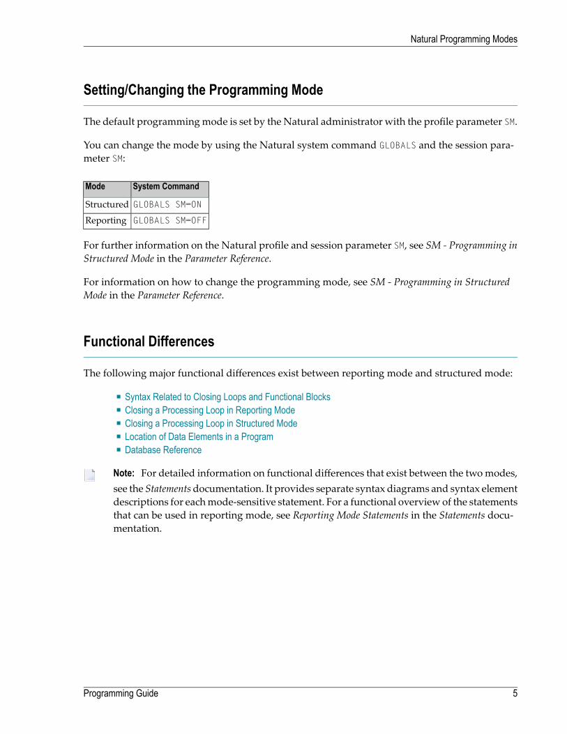
Setting/Changing the Programming Mode
The default programmingmode is set by the Natural administrator with the profile parameter SM.
You can change the mode by using the Natural system command GLOBALS and the session para-meter SM:
System CommandMode
GLOBALS SM=ONStructured
GLOBALS SM=OFFReporting
For further information on the Natural profile and session parameter SM, see SM - Programming inStructured Mode in the Parameter Reference.
For information on how to change the programming mode, see SM - Programming in StructuredMode in the Parameter Reference.
Functional Differences
The following major functional differences exist between reporting mode and structured mode:
■ Syntax Related to Closing Loops and Functional Blocks■ Closing a Processing Loop in Reporting Mode■ Closing a Processing Loop in Structured Mode■ Location of Data Elements in a Program■ Database Reference
Note: For detailed information on functional differences that exist between the twomodes,see the Statementsdocumentation. It provides separate syntax diagrams and syntax elementdescriptions for eachmode-sensitive statement. For a functional overview of the statementsthat can be used in reporting mode, see Reporting Mode Statements in the Statements docu-mentation.
5Programming Guide
Natural Programming Modes

Syntax Related to Closing Loops and Functional Blocks
(CLOSE) LOOP and DO ... DOEND statements are used for this purpose.
END-... statements (except END-DEFINE, END-DECIDE and END-SUBROUTINE) cannot beused.
Reporting Mode:
Every loop or logical construct must be explicitly closed with a corresponding END-...statement. Thus, it becomes immediately clear, which loop/logical constructs ends where.
LOOP and DO/DOEND statements cannot be used.
Structured Mode:
The two examples below illustrate the differences between the twomodes in constructingprocessingloops and logical conditions.
Reporting Mode Example:
The reporting mode example uses the statements DO and DOEND to mark the beginning and end ofthe statement block that is based on the AT END OF DATA condition. The END statement closes allactive processing loops.
READ EMPLOYEES BY PERSONNEL-IDDISPLAY NAME BIRTHAT END OF DATA
DOSKIP 2WRITE / 'LAST SELECTED:' OLD(NAME)
DOENDEND
Structured Mode Example:
The structuredmode example uses an END-ENDDATA statement to close the AT END OF DATA condi-tion, and an END-READ statement to close the READ loop. The result is a more clearly structuredprogram in which you can see immediately where each construct begins and ends:
DEFINE DATA LOCAL1 MYVIEW VIEW OF EMPLOYEES
2 PERSONNEL-ID2 NAME2 BIRTH
END-DEFINEREAD MYVIEW BY PERSONNEL-ID
DISPLAY NAME BIRTHAT END OF DATA
SKIP 2WRITE / 'LAST SELECTED:' OLD(NAME)
END-ENDDATA
Programming Guide6
Natural Programming Modes

END-READEND
Closing a Processing Loop in Reporting Mode
The statements END, LOOP (or CLOSE LOOP) or SORTmay be used to close a processing loop.
The LOOP statement can be used to close more than one loop, and the END statement can be usedto close all active loops. These possibilities of closing several loopswith a single statement constitutea basic difference to structured mode.
A SORT statement closes all processing loops and initiates another processing loop.
Example 1 - LOOP:
FIND ...FIND .........LOOP /* closes inner FIND loop
LOOP /* closes outer FIND loop......
Example 2 - END:
FIND ...FIND .........
END /* closes all loops and ends processing
Example 3 - SORT:
FIND ...FIND .........
SORT ... /* closes all loops, initiates loop...END /* closes SORT loop and ends processing
7Programming Guide
Natural Programming Modes

Closing a Processing Loop in Structured Mode
Structured mode uses a specific loop-closing statement for each processing loop. Also, the ENDstatement does not close any processing loop. The SORT statementmust be preceded by an END-ALLstatement, and the SORT loop must be closed with an END-SORT statement.
Example 1 - FIND:
FIND ...FIND .........END-FIND /* closes inner FIND loop
END-FIND /* closes outer FIND loop...
Example 2 - READ:
READ ...AT END OF DATA...END-ENDDATA...
END-READ /* closes READ loop......END
Example 3 - SORT:
READ ...FIND .........
END-ALL /* closes all loopsSORT /* opens loop......END-SORT /* closes SORT loopEND
Programming Guide8
Natural Programming Modes

Location of Data Elements in a Program
In reporting mode, you can use database fields without having to define them in a DEFINE DATAstatement; also, you can define user-defined variables anywhere in a program, which means thatthey can be scattered all over the program.
In structured mode, all data elements to be used have to be defined in one central location (eitherin the DEFINE DATA statement at the beginning of the program, or in a data area outside the pro-gram).
Database Reference
Reporting Mode:
In reportingmode, database fields and data definitionmodules (DDMs)may be referencedwithouthaving been defined in a data area.
Structured Mode:
In structured mode, each database field to be used must be specified in a DEFINE DATA statementas described in Defining Fields and Accessing Data in an Adabas Database.
9Programming Guide
Natural Programming Modes
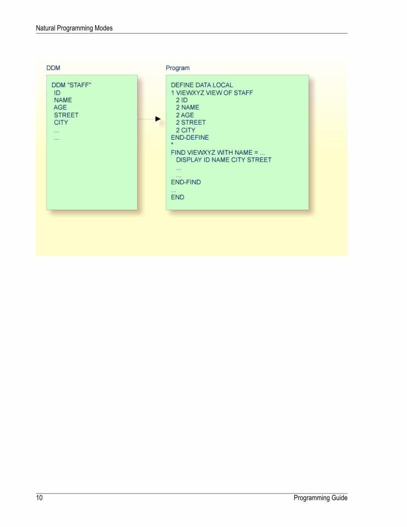
Programming Guide10
Natural Programming Modes

II Object Types
This part describes the various types of Natural programming objects that can be used to achievean efficient application structure. AllNatural objects are stored inNatural libraries. Natural librariesare contained in Natural system files.
Using Natural Programming Objects
Data Areas
Programs, Functions, Subprograms and Subroutines
Processing a Rich GUI Page - Adapter
Maps
Helproutines
Multiple Use of Source Code - Copycode
Documenting Natural Objects - Text
Creating Event Driven Applications - Dialog
Creating Component Based Applications - Class
Using Non-Natural Files - Resource
11

12

2 Using Natural Programming Objects
■ Types of Programming Objects .......................................................................................................... 14■ Creating and Maintaining Programming Objects .................................................................................... 14
13

Types of Programming Objects
Within a Natural application, you can use the following types of programming objects:
■ Program■ Class■ Subprogram■ Function■ Adapter■ Subroutine■ Copycode■ Helproutine■ Text■ Dialog■ Map■ Local Data Area■ Global Data Area■ Parameter Data Area■ Resource
Creating and Maintaining Programming Objects
To create and maintain the programming objects, you use the Natural editors.
■ Local data areas, global data areas and parameter data areas are created and maintained withthe data area editor.
■ Maps are created and maintained with the map editor.■ Dialogs are created and maintained with the dialog editor.■ Classes are created and maintained with the Class Builder.■ All other types of objects listed above are created and maintained with the program editor.
For information about the naming conventions that apply to Natural objects, see Object NamingConventions.
Programming Guide14
Using Natural Programming Objects

For detailed information on using these objects, see Creating, Maintaining and Executing NaturalObjects in Using Natural Studio.
15Programming Guide
Using Natural Programming Objects

16

3 Data Areas
■ Use of Data Areas ........................................................................................................................... 18■ Local Data Area .............................................................................................................................. 18■ Global Data Area ............................................................................................................................. 19■ Parameter Data Area ....................................................................................................................... 28
17

Use of Data Areas
As explained in Defining Fields, all fields that are to be used in a program have to be defined ina DEFINE DATA statement.
The fields can be defined within the DEFINE DATA statement itself; or they can be defined outsidethe program in a separate data area, with the DEFINE DATA statement referencing that data area.
A separate data area is a Natural object that can be used by multiple Natural programs, subpro-grams, subroutines, helproutines, dialogs or classes. A data area contains data element definitions,such as user-defined variables, constants and database fields from adata definitionmodule (DDM).
All data areas are created and edited with the data area editor.
Natural supports three types of data area:
■ Local Data Area■ Global Data Area■ Parameter Data Area
Local Data Area
Variables defined as local are used only within a single Natural programming object. There aretwo options for defining local data:
■ Define local data within a program.■ Define local data outside a program in a separate Natural programming object, a local data area(LDA).
Such a local data area is initialized when a program, subprogram or external subroutine thatuses this local data area starts to execute.
For a clear application structure and for easier maintainability, it is usually better to define fieldsin data areas outside the programs.
Example 1 - Fields Defined Directly within a DEFINE DATA Statement:
In the following example, the fields are defined directly within the DEFINE DATA statement of theprogram.
Programming Guide18
Data Areas

DEFINE DATA LOCAL1 VIEWEMP VIEW OF EMPLOYEES
2 NAME2 FIRST-NAME2 PERSONNEL-ID
1 #VARI-A (A20)1 #VARI-B (N3.2)1 #VARI-C (I4)END-DEFINE...
Example 2 - Fields Defined in a Separate Data Area:
In the following example, the same fields are not defined in the DEFINE DATA statement of theprogram, but in an LDA, named LDA39, and the DEFINE DATA statement in the program containsonly a reference to that data area.
Program:
DEFINE DATA LOCALUSING LDA39
END-DEFINE...
Local Data Area LDA39:
I T L Name F Length Miscellaneous All -- -------------------------------- - ---------- -------------------------> V 1 VIEWEMP EMPLOYEES 2 PERSONNEL-ID A 8 2 FIRST-NAME A 20 2 NAME A 20 1 #VARI-A A 20 1 #VARI-B N 3.2 1 #VARI-C I 4 ↩
Global Data Area
The following topics are covered below:
■ Creating and Referencing a GDA■ Creating and Deleting GDA Instances
19Programming Guide
Data Areas

■ Data Blocks
Creating and Referencing a GDA
GDAs are created and modified with the data area editor. For further information, refer to DataArea Editor in the Editors documentation.
A GDA that is referenced by a Natural programming object must be stored in the same Naturallibrary (or a steplib defined for this library) where the object that references this GDA is stored.
Note: Using a GDA named COMMON for startup:If a GDAnamed COMMON exists in a library, the programnamed ACOMMON is invoked automat-ically when you LOGON to that library.
Important: When you build an application where multiple Natural programming objectsreference a GDA, remember that modifications to the data element definitions in the GDAaffect all Natural programming objects that reference that data area. Therefore these objectsmust be recompiled by using the CATALOG or STOW command after the GDA has been modi-fied.
To use a GDA, a Natural programming object must reference it with the GLOBAL clause of theDEFINE DATA statement. Each Natural programming object can reference only one GDA; that is,a DEFINE DATA statement must not contain more than one GLOBAL clause.
Creating and Deleting GDA Instances
The first instance of aGDA is created and initialized at runtimewhen the firstNatural programmingobject that references it starts to execute.
Once a GDA instance has been created, the data values it contains can be shared by all Naturalprogramming objects that reference thisGDA (DEFINE DATA GLOBAL statement) and that are invokedby a PERFORM, INPUT or FETCH statement. All objects that share a GDA instance are operating onthe same data elements.
A new GDA instance is created if the following applies:
■ A subprogram that references a GDA (any GDA) is invoked with a CALLNAT statement.■ A subprogram that does not reference a GDA invokes a programming object that references aGDA (any GDA).
If a new instance of a GDA is created, the current GDA instance is suspended and the data valuesit contains are stacked. The subprogram then references the data values in the newly created GDAinstance. The data values in the suspended GDA instance or instances is inaccessible. A program-ming object only refers to one GDA instance and cannot access any previous GDA instances. AGDA data element can only be passed to a subprogram by defining the element as a parameterin the CALLNAT statement.
Programming Guide20
Data Areas
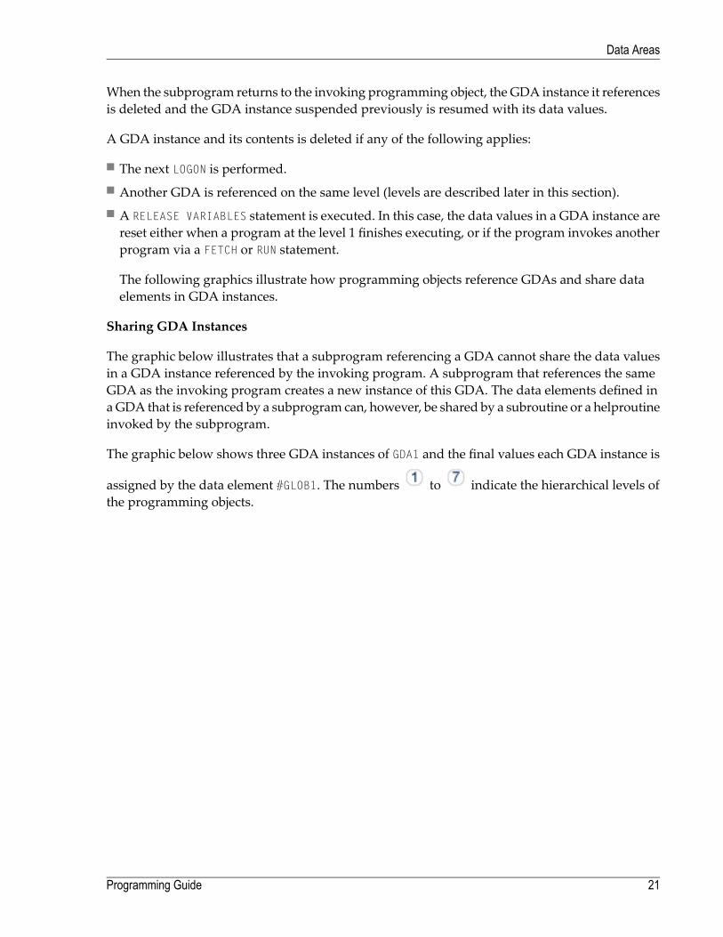
When the subprogram returns to the invoking programming object, the GDA instance it referencesis deleted and the GDA instance suspended previously is resumed with its data values.
A GDA instance and its contents is deleted if any of the following applies:
■ The next LOGON is performed.■ Another GDA is referenced on the same level (levels are described later in this section).■ A RELEASE VARIABLES statement is executed. In this case, the data values in a GDA instance arereset either when a program at the level 1 finishes executing, or if the program invokes anotherprogram via a FETCH or RUN statement.
The following graphics illustrate how programming objects reference GDAs and share dataelements in GDA instances.
Sharing GDA Instances
The graphic below illustrates that a subprogram referencing a GDA cannot share the data valuesin a GDA instance referenced by the invoking program. A subprogram that references the sameGDA as the invoking program creates a new instance of this GDA. The data elements defined inaGDA that is referenced by a subprogram can, however, be shared by a subroutine or a helproutineinvoked by the subprogram.
The graphic below shows three GDA instances of GDA1 and the final values each GDA instance is
assigned by the data element #GLOB1. The numbers to indicate the hierarchical levels ofthe programming objects.
21Programming Guide
Data Areas

Using FETCH or FETCH RETURN
The graphic below illustrates that programs referencing the same GDA and invoking one anotherwith the FETCH or FETCH RETURN statement share the data elements defined in this GDA. If any ofthese programs does not reference a GDA, the instance of the GDA referenced previously remainsactive and the values of the data elements are retained.
The numbers and indicate the hierarchical levels of the programming objects.
Programming Guide22
Data Areas
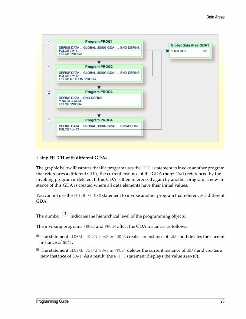
Using FETCH with different GDAs
The graphic below illustrates that if a programuses the FETCH statement to invoke another programthat references a different GDA, the current instance of the GDA (here: GDA1) referenced by theinvoking program is deleted. If this GDA is then referenced again by another program, a new in-stance of this GDA is created where all data elements have their initial values.
You cannot use the FETCH RETURN statement to invoke another program that references a differentGDA.
The number indicates the hierarchical level of the programming objects.
The invoking programs PROG3 and PROG4 affect the GDA instances as follows:
■ The statement GLOBAL USING GDA2 in PROG3 creates an instance of GDA2 and deletes the currentinstance of GDA1.
■ The statement GLOBAL USING GDA1 in PROG4 deletes the current instance of GDA2 and creates anew instance of GDA1. As a result, the WRITE statement displays the value zero (0).
23Programming Guide
Data Areas
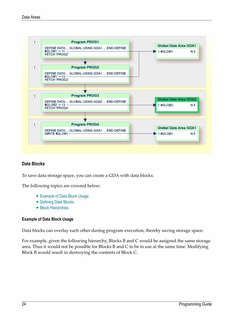
Data Blocks
To save data storage space, you can create a GDA with data blocks.
The following topics are covered below:
■ Example of Data Block Usage■ Defining Data Blocks■ Block Hierarchies
Example of Data Block Usage
Data blocks can overlay each other during program execution, thereby saving storage space.
For example, given the following hierarchy, Blocks B and C would be assigned the same storagearea. Thus it would not be possible for Blocks B and C to be in use at the same time. ModifyingBlock B would result in destroying the contents of Block C.
Programming Guide24
Data Areas
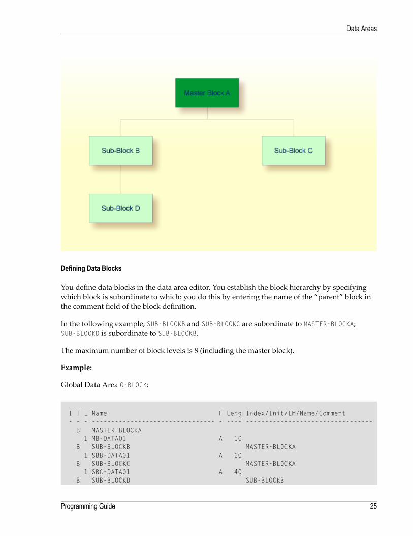
Defining Data Blocks
You define data blocks in the data area editor. You establish the block hierarchy by specifyingwhich block is subordinate to which: you do this by entering the name of the “parent” block inthe comment field of the block definition.
In the following example, SUB-BLOCKB and SUB-BLOCKC are subordinate to MASTER-BLOCKA;SUB-BLOCKD is subordinate to SUB-BLOCKB.
The maximum number of block levels is 8 (including the master block).
Example:
Global Data Area G-BLOCK:
I T L Name F Leng Index/Init/EM/Name/Comment- - - -------------------------------- - ---- ---------------------------------
B MASTER-BLOCKA1 MB-DATA01 A 10
B SUB-BLOCKB MASTER-BLOCKA1 SBB-DATA01 A 20
B SUB-BLOCKC MASTER-BLOCKA1 SBC-DATA01 A 40
B SUB-BLOCKD SUB-BLOCKB
25Programming Guide
Data Areas

1 SBD-DATA01 A 40
To make the specific blocks available to a program, you use the following syntax in the DEFINEDATA statement:
Program 1:
DEFINE DATA GLOBALUSING G-BLOCKWITH MASTER-BLOCKA
END-DEFINE
Program 2:
DEFINE DATA GLOBALUSING G-BLOCKWITH MASTER-BLOCKA.SUB-BLOCKB
END-DEFINE
Program 3:
DEFINE DATA GLOBALUSING G-BLOCKWITH MASTER-BLOCKA.SUB-BLOCKC
END-DEFINE
Program 4:
DEFINE DATA GLOBALUSING G-BLOCKWITH MASTER-BLOCKA.SUB-BLOCKB.SUB-BLOCKD
END-DEFINE
With this structure, Program 1 can share the data in MASTER-BLOCKAwith Program 2, Program 3or Program 4. However, Programs 2 and 3 cannot share the data areas of SUB-BLOCKB andSUB-BLOCKC because these data blocks are defined at the same level of the structure and thus occupythe same storage area.
Programming Guide26
Data Areas

Block Hierarchies
Care needs to be taken when using data block hierarchies. Let us assume the following scenariowith three programs using a data block hierarchy:
Program 1:
DEFINE DATA GLOBALUSING G-BLOCKWITH MASTER-BLOCKA.SUB-BLOCKB
END-DEFINE*MOVE 1234 TO SBB-DATA01FETCH 'PROGRAM2'END
Program 2:
DEFINE DATA GLOBALUSING G-BLOCKWITH MASTER-BLOCKA
END-DEFINE*FETCH 'PROGRAM3'END
Program 3:
DEFINE DATA GLOBALUSING G-BLOCKWITH MASTER-BLOCKA.SUB-BLOCKB
END-DEFINE*WRITE SBB-DATA01END
Explanation:
■ Program1uses the global data area G-BLOCKwith MASTER-BLOCKA and SUB-BLOCKB. The programmodifies a field in SUB-BLOCKB and fetches Program 2 which specifies only MASTER-BLOCKA inits data definition.
■ Program 2 resets (deletes the contents of) SUB-BLOCKB. The reason is that a program on Level 1(for example, a program calledwith a FETCH statement) resets any data blocks that are subordinateto the blocks it defines in its own data definition.
■ Program 2 now fetches Program 3 which is to display the field modified in Program 1, but itreturns an empty screen.
For details on program levels, seeMultiple Levels of Invoked Objects.
27Programming Guide
Data Areas

Parameter Data Area
A subprogram is invoked with a CALLNAT statement. With the CALLNAT statement, parameters canbe passed from the invoking object to the subprogram.
These parameters must be defined with a DEFINE DATA PARAMETER statement in the subprogram:
■ they can be defined in the PARAMETER clause of the DEFINE DATA statement itself; or■ they can be defined in a separate parameter data area,with the DEFINE DATA PARAMETER statementreferencing that PDA.
The following topics are covered below:
■ Parameters Defined within DEFINE DATA PARAMETER Statement
Programming Guide28
Data Areas

■ Parameters Defined in Parameter Data Area
Parameters Defined within DEFINE DATA PARAMETER Statement
29Programming Guide
Data Areas

Parameters Defined in Parameter Data Area
In the same way, parameters that are passed to an external subroutine via a PERFORM statementmust be defined with a DEFINE DATA PARAMETER statement in the external subroutine.
In the invoking object, the parameter variables passed to the subprogram/subroutine need not bedefined in a PDA; in the illustrations above, they are defined in the LDA used by the invokingobject (but they could also be defined in a GDA).
The sequence, format and length of the parameters specified with the CALLNAT/PERFORM statementin the invoking object must exactly match the sequence, format and length of the fields specifiedin the DEFINE DATA PARAMETER statement of the invoked subprogram/subroutine. However, thenames of the variables in the invoking object and the invoked subprogram/subroutine need notbe the same (as the parameter data are transferred by address, not by name).
To guarantee that the data element definitions used in the invoking program are identical to thedata element definitions used in the subprogram or external subroutine, you can specify a PDA
Programming Guide30
Data Areas

in a DEFINE DATA LOCAL USING statement. By using a PDAas an LDAyou can avoid the extra effortof creating an LDA that has the same structure as the PDA.
31Programming Guide
Data Areas

32

4 Programs, Functions, Subprograms and Subroutines
■ A Modular Application Structure ......................................................................................................... 34■ Multiple Levels of Invoked Objects ...................................................................................................... 34■ Program ........................................................................................................................................ 36■ Function ........................................................................................................................................ 39■ Subroutine ..................................................................................................................................... 41■ Subprogram ................................................................................................................................... 46■ Processing Flow when Invoking a Routine ............................................................................................ 48
33

This document discusses those object typeswhich can be invoked as routines; that is, as subordinateprograms.
Helproutines and maps, although they are also invoked from other objects, are strictly speakingnot routines as such, and are therefore discussed in separate documents; see Helproutines andMaps.
A Modular Application Structure
Typically, a Natural application does not consist of a single huge program, but is split into severalmodules. Each of these modules will be a functional unit of manageable size, and each module isconnected to the other modules of the application in a clearly defined way. This provides for awell structured application, which makes its development and subsequent maintenance a loteasier and faster.
During the execution of amain program, other programs, subprograms, subroutines, helproutinesandmaps can be invoked. These objects can in turn invoke other objects (for example, a subroutinecan itself invoke another subroutine). Thus, the modular structure of an application can becomequite complex and extend over several levels.
Multiple Levels of Invoked Objects
Each invoked object is one level below the level of the object from which it was invoked; that is,with each invocation of a subordinate object, the level number is incremented by 1.
Anyprogram that is directly executed is at Level 1; any subprogram, subroutine,map or helproutinedirectly invoked by themain program is at Level 2; when such a subroutine in turn invokes anothersubroutine, the latter is at Level 3.
A program invoked with a FETCH statement from within another object is classified as a mainprogram, operating from Level 1. A program that is invoked with FETCH RETURN, however, isclassified as a subordinate program and is assigned a level one below that of the invoking object.
The following illustration is an example of multiple levels of invoked objects and also shows howthese levels are counted:
Programming Guide34
Programs, Functions, Subprograms and Subroutines

If you wish to ascertain the level number of the object that is currently being executed, you canuse the system variable *LEVEL (which is described in the System Variables documentation).
This document discusses the following Natural object types, which can be invoked as routines(that is, subordinate programs):
■ program■ function■ subroutine■ subprogram
Helproutines and maps, although they are also invoked from other objects, are strictly speakingnot routines as such, and are therefore discussed in separate documents; see Helproutines andMaps.
Basically, programs, subprograms and subroutines differ from one another in the way data canbe passed between them and in their possibilities of sharing each other's data areas. Therefore thedecision which object type to use for which purpose depends very much on the data structure ofyour application.
35Programming Guide
Programs, Functions, Subprograms and Subroutines

Program
A program can be executed - and thus tested - by itself.
■ To compile and execute a source program, you use the system command RUN.■ To execute a program that already exists in compiled form, you use the system commandEXECUTE.
A program can also be invoked from another object with a FETCH or FETCH RETURN statement. Theinvoking object can be another program, a subprogram, function, subroutine or helproutine.
■ When a program is invoked with FETCH RETURN, the execution of the invoking object will besuspended - not terminated - and the fetched programwill be activated as a subordinate program.When the execution of the FETCHed program is terminated, the invoking objectwill be re-activatedand its execution continued with the statement following the FETCH RETURN statement.
■ When a program is invoked with FETCH, the execution of the invoking object will be terminatedand the FETCHed program will be activated as a main program. The invoking object will not bere-activated upon termination of the fetched program.
The following topics are covered below:
■ Program Invoked with FETCH RETURN
Programming Guide36
Programs, Functions, Subprograms and Subroutines
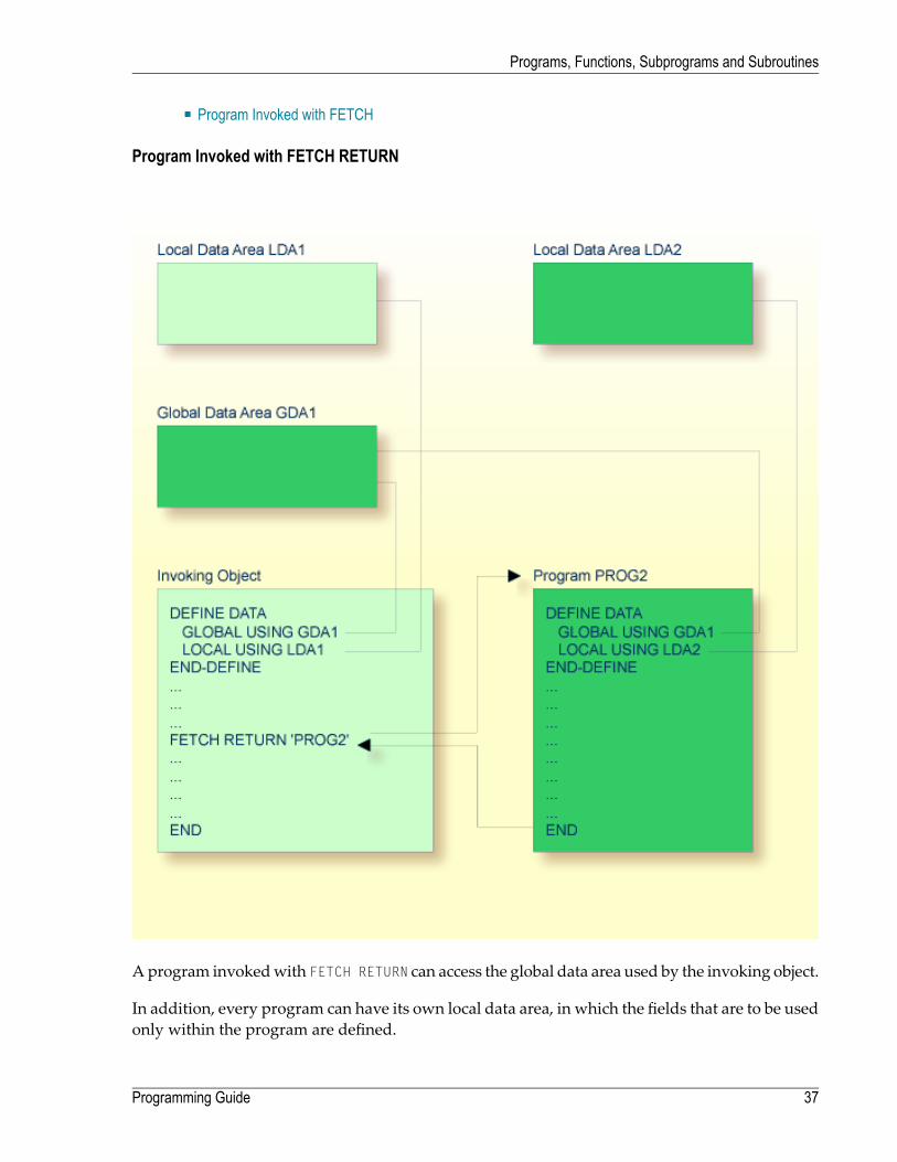
■ Program Invoked with FETCH
Program Invoked with FETCH RETURN
Aprogram invokedwith FETCH RETURN can access the global data area used by the invoking object.
In addition, every program can have its own local data area, in which the fields that are to be usedonly within the program are defined.
37Programming Guide
Programs, Functions, Subprograms and Subroutines

However, a program invoked with FETCH RETURN cannot have its own global data area.
Program Invoked with FETCH
A program invoked with FETCH as a main program usually establishes its own global data area(as shown in the illustration above). However, it could also use the same global data area as estab-lished by the invoking object.
Note: A source program can also be invoked with a RUN statement; see the RUN statementin the Statements documentation.
Programming Guide38
Programs, Functions, Subprograms and Subroutines

Function
The Natural object of type function contains one DEFINE FUNCTION statement for the definition ofa single function and the END statement. The function itself can be invoked using the function callsyntax.
The basic structure of the DEFINE FUNCTION statement is like this:
DEFINE FUNCTION function-nameRETURNS ...DEFINE DATA...END-DEFINE
statements ...
END-FUNCTION
And the function call has the structure:
function-name (< ... >)
The DEFINE FUNCTION statement offers the keyword RETURNS for the result value of a function.With the DEFINE DATA statement, the parameters for the function call aswell as local and independ-ent variables for the function logic can be defined. A global data area (for example, GDA1) cannotbe referenced inside the function definition.
The block of statements after the RETURNS keyword and the DEFINE DATA statement must containall those statements which are to be executed when the function is called.
Parameter data areas (for example, PDA1) may be used to access parameters for function calls andfunction definitions in order to minimize the maintainance effort when changing parameters.
The function call can be used either as an operand within a Natural statement or stand-alone inplace of a Natural statement. The arguments of the function call must be specified using a specialbracket notation: (<...>).
The DEFINE PROTOTYPE statement may be used to define the result and parameter layouts for acertain function. This may be considered if the function is not yet available or if a variable functioncall is to be used. At compilation time, the type of the result variable and the parameters will bechecked.
The DEFINE PROTOTYPE statement may be included in a copycode object if the function call, andtherefore the prototype definition can be used in several programming objects.
For further information, see the section User-Defined Functions.
39Programming Guide
Programs, Functions, Subprograms and Subroutines
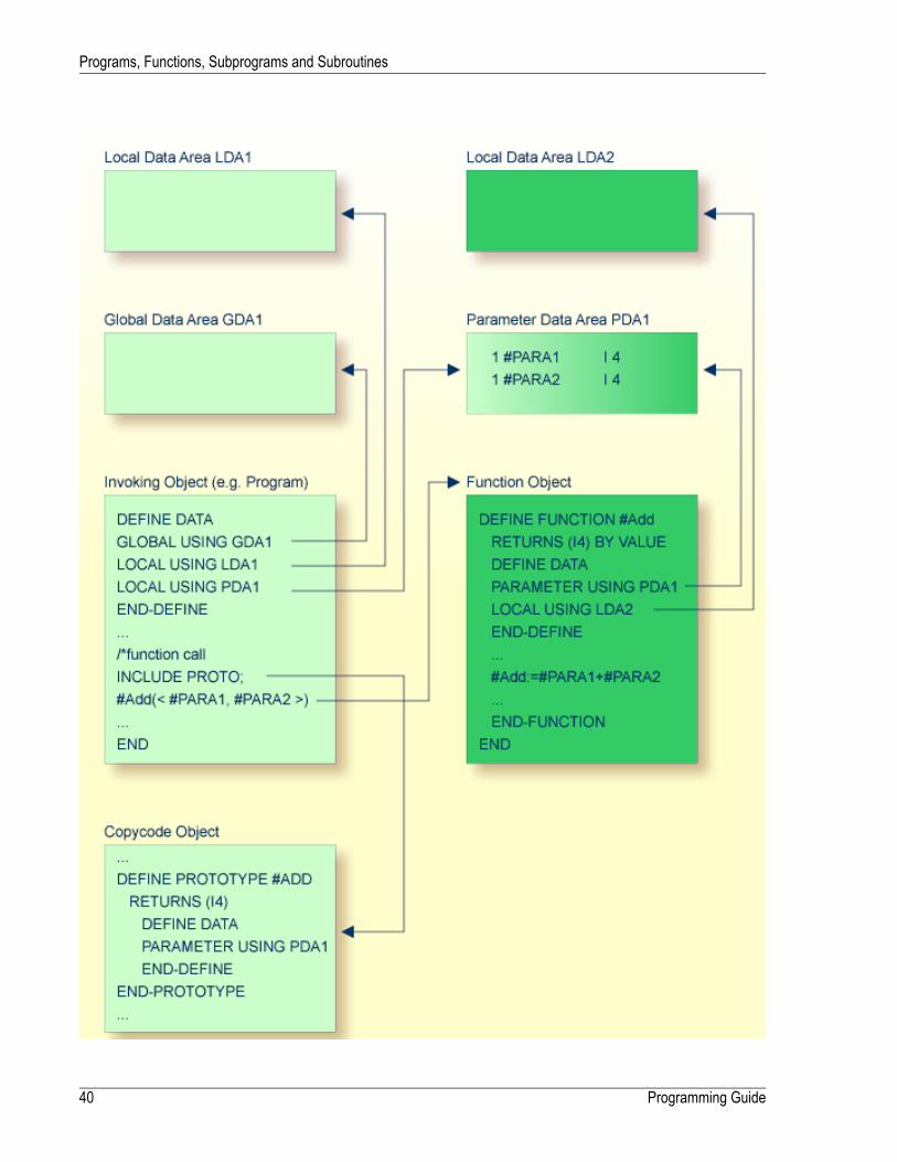
Programming Guide40
Programs, Functions, Subprograms and Subroutines

Subroutine
The statements that make up a subroutine must be defined within a DEFINE SUBROUTINE ...END-SUBROUTINE statement block.
A subroutine is invoked with a PERFORM statement.
A subroutine may be an inline subroutine or an external subroutine:
■ Inline SubroutineAn inline subroutine is defined within the object which contains the PERFORM statement that in-vokes it.
■ External SubroutineAn external subroutine is defined in a separate object - of type subroutine - outside the objectwhich invokes it.
If you have a block of code which is to be executed several times within an object, it is useful touse an inline subroutine. You then only have to code this block once within a DEFINE SUBROUTINEstatement block and invoke it with several PERFORM statements.
The following topics are covered below:
■ Inline Subroutine■ Data Available to an Inline Subroutine■ External Subroutine
41Programming Guide
Programs, Functions, Subprograms and Subroutines

■ Data Available to an External Subroutine
Inline Subroutine
Programming Guide42
Programs, Functions, Subprograms and Subroutines

43Programming Guide
Programs, Functions, Subprograms and Subroutines
An inline subroutine can be contained within a programming object of type program, function,subprogram, subroutine or helproutine.
If an inline subroutine is so large that it impairs the readability of the object inwhich it is contained,you may consider putting it into an external subroutine, so as to enhance the readability of yourapplication.
Data Available to an Inline Subroutine
An inline subroutine has access to the local data area and the global data area used by the objectin which it is contained.
Programming Guide44
Programs, Functions, Subprograms and Subroutines

External Subroutine
An external subroutine - that is, an object of type subroutine - cannot be executed by itself. It mustbe invoked from another object. The invoking object can be a program, function, subprogram,subroutine or helproutine.
45Programming Guide
Programs, Functions, Subprograms and Subroutines

Data Available to an External Subroutine
An external subroutine can access the global data area used by the invoking object.
Moreover, parameters can be passed with the PERFORM statement from the invoking object to theexternal subroutine. These parameters must be defined either in the DEFINE DATA PARAMETERstatement of the subroutine, or in a parameter data area used by the subroutine.
In addition, an external subroutine can have its local data area, in which the fields that are to beused only within the subroutine are defined.
However, an external subroutine cannot have its own global data area.
Subprogram
Typically, a subprogram would contain a generally available standard function that is used byvarious objects in an application.
A subprogram cannot be executed by itself. It must be invoked from another object. The invokingobject can be a program, function, subprogram, subroutine or helproutine.
A subprogram is invoked with a CALLNAT statement.
When the CALLNAT statement is executed, the execution of the invoking object will be suspendedand the subprogram executed. After the subprogram has been executed, the execution of the in-voking object will be continued with the statement following the CALLNAT statement.
Data Available to a Subprogram
With the CALLNAT statement, parameters can be passed from the invoking object to the subprogram.These parameters are the only data available to the subprogram from the invoking object. Theymust be defined either in the DEFINE DATA PARAMETER statement of the subprogram, or in a para-meter data area used by the subprogram.
Programming Guide46
Programs, Functions, Subprograms and Subroutines

In addition, a subprogram can have its own local data area, in which the fields to be used withinthe subprogram are defined.
If a subprogram in turn invokes a subroutine or helproutine, it can also establish its own globaldata area to be shared with the subroutine/helproutine.
47Programming Guide
Programs, Functions, Subprograms and Subroutines

Processing Flow when Invoking a Routine
When the CALLNAT, PERFORM or FETCH RETURN statement that invokes a routine - a subprogram, anexternal subroutine, or a program respectively - is executed, the execution of the invoking objectis suspended and the execution of the routine begins.
The execution of the routine continues until either its END statement is reached or processing ofthe routine is stopped by an ESCAPE ROUTINE statement being executed.
In either case, processing of the invoking object will then continue with the statement followingthe CALLNAT, PERFORM or FETCH RETURN statement used to invoke the routine.
Programming Guide48
Programs, Functions, Subprograms and Subroutines

Example:
49Programming Guide
Programs, Functions, Subprograms and Subroutines

50

5 Processing a Rich GUI Page - Adapter
TheNatural object of type “adapter” is used to represent a rich GUI page in a Natural application.This object type plays a similar role for the processing of a rich GUI page as the object type mapplays for terminal I/O processing. But it is different from a map in that it does not contain layoutinformation.
An object of type adapter is generated from an external page layout. It serves as an interface thatenables a Natural application to send data to an external I/O system for presentation andmodific-ation, using an externally defined and stored page layout. The adapter contains the Natural codenecessary to perform this task.
An application program refers to an adapter in the PROCESS PAGE USING statement.
For information on the object type “adapter”, see the Natural for Ajax documentation.
51

52

6 Maps
■ Benefits of Using Maps ..................................................................................................................... 54■ Types of Maps ................................................................................................................................ 54■ Creating Maps ................................................................................................................................ 55■ Starting/Stopping Map Processing ...................................................................................................... 55
53
As an alternative to specifying screen layouts dynamically, the INPUT statement offers the possib-ility to use predefined map layouts which makes use of the Natural object type “map”.
Benefits of Using Maps
Using predefined map layouts rather than dynamic screen-layout specifications offers variousadvantages such as:
■ Clearly structured applications as a result of a consequent separation of program logic anddisplay logic.
■ Map layout modifications possible without making changes to the main programs.■ The language of an applications's user interface can be easily adapted for internationalizationor localization.
The benefit of using programming objects such as maps will become obvious when it comes tomaintaining existing Natural applications.
Types of Maps
Maps (screen layouts) are those parts of an application which the users see on their screens.
The following types of maps exist:
■ Input MapThe dialog with the user is carried out via input maps.
■ Output MapIf an application produces any output report, this report can be displayed on the screen by usingan output map.
■ Help MapHelpmaps are, in principle, like any othermaps, but when they are assigned as help, additionalchecks are performed to ensure their usability for help purpose.
The object type “map” comprises
■ the map body which defines the screen layout and■ an associated parameter data area (PDA) which, as a sort of interface, contains data definitionssuch as name, format, length of each field presented on a specific map.
Related Topics:
Programming Guide54
Maps

■ For information on selection boxes that can be attached to input fields, see SB - Selection Box inthe INPUT statement documentation and SB - Selection Box in the Parameter Reference.
■ For information on split screen maps where the upper portion may be used as an output mapand the lower portion as an inputmap, see Split-Screen Feature in the INPUT statement document-ation.
Creating Maps
Maps and help map layouts are created and edited in the map editor.
The appropriate local data area (LDA) is created and maintained in the data area editor.
Depending on the platform on which Natural is installed, these editors have either a characteruser interface or a graphical user interface.
Related Topics:
■ For information on using the data area editor, seeData Area Editor in the platform-specific Editorsdocumentation.
■ For information on using the map editor, seeMap Editor in the platform-specific Editors docu-mentation.
■ For information on input processing using screen layouts specified dynamically, see Syntax 1 -Dynamic Screen Layout Specification in the INPUT statement documentation.
■ For information on input processing using amap layout createdwith themap editor, see Syntax2 - Using Predefined Map Layout in the INPUT statement documentation.
Starting/Stopping Map Processing
An input map is invoked with an INPUT USING MAP statement.
An output map is invoked with a WRITE USING MAP statement.
Processing of a map can be stopped with an ESCAPE ROUTINE statement in a processing rule.
55Programming Guide
Maps

56
7 Helproutines
■ Invoking Help ................................................................................................................................. 58■ Specifying Helproutines .................................................................................................................... 58■ Programming Considerations for Helproutines ....................................................................................... 59■ Passing Parameters to Helproutines ................................................................................................... 59■ Equal Sign Option ........................................................................................................................... 60■ Array Indices .................................................................................................................................. 61■ Help as a Window ........................................................................................................................... 61
57
Helproutines have specific characteristics to facilitate the processing of help requests. They maybe used to implement complex and interactive help systems. They are created with the programeditor.
Invoking Help
A Natural user can invoke a Natural helproutine either by entering the help character in a field,or by pressing the help key (usually PF1). The default help character is a question mark (?).
■ The help character must be entered only once.■ The help character must be the only character modified in the input string.■ The help character must be the first character in the input string.
If a helproutine is specified for a numeric field, Natural will allow a question mark to be enteredfor the purpose of invoking the helproutine for that field. Natural will still check that valid numericdata are provided as field input.
If not already specified, the help key may be specified with the SET KEY statement:
SET KEY PF1=HELP
A helproutine can only be invoked by a user if it has been specified in the program ormap fromwhich it is to be invoked.
Specifying Helproutines
A helproutine may be specified:
■ in a program: at statement level and at field level;■ in a map: at map level and at field level.
If a user requests help for a field for which no help has been specified, or if a user requests helpwithout a field being referenced, the helproutine specified at the statement ormap level is invoked.
Ahelproutinemay also be invoked byusing a REINPUT USING HELP statement (either in the programitself or in a processing rule). If the REINPUT USING HELP statement contains a MARK option, thehelproutine assigned to the marked field is invoked. If no field-specific helproutine is assigned,the map helproutine is invoked.
A REINPUT statement in a helproutine may only apply to INPUT statements within the same hel-proutine.
Programming Guide58
Helproutines

The name of a helproutine may be specified either with the session parameter HE of an INPUTstatement:
INPUT (HE='HELP2112')
or by using the extended field editing facility of themap editor (seeCreatingMaps and the Editorsdocumentation).
The name of a helproutine may be specified as an alphanumeric constant or as an alphanumericvariable containing the name. If it is a constant, the name of the helproutine must be specifiedwithin apostrophes.
Programming Considerations for Helproutines
Processing of a helproutine can be stopped with an ESCAPE ROUTINE statement.
Be careful when using END OF TRANSACTION or BACKOUT TRANSACTION statements in a helproutine,because this will affect the transaction logic of the main program.
Passing Parameters to Helproutines
A helproutine can access the currently active global data area (but it cannot have its own globaldata area). In addition, it can have its own local data area.
Data may also be passed from/to a helproutine via parameters. A helproutine may have up to 20explicit parameters and one implicit parameter. The explicit parameters are specified with the HEoperand after the helproutine name:
HE='MYHELP','001'
The implicit parameter is the field for which the helproutine was invoked:
INPUT #A (A5) (HE='YOURHELP','001')
where 001 is an explicit parameter and #A is the implicit parameter/the field.
This is specified within the DEFINE DATA PARAMETER statement of the helproutine as:
59Programming Guide
Helproutines

DEFINE DATA PARAMETER1 #PARM1 (A3) /* explicit parameter1 #PARM2 (A5) /* implicit parameterEND-DEFINE
Please note that the implicit parameter (#PARM2 in the above example)may be omitted. The implicitparameter is used to access the field for which help was requested, and to return data from thehelproutine to the field. For example, youmight implement a calculator program as a helproutineand have the result of the calculations returned to the field.
When help is called, the helproutine is called before the data are passed from the screen to theprogram data areas. This means that helproutines cannot access data entered within the samescreen transaction.
Once help processing is complete, the screen data will be refreshed: any fields which have beenmodified by the helproutine will be updated - excluding fields which had been modified by theuser before the helproutine was invoked, but including the field for which help was requested.Exception: If the field forwhich helpwas requested is split into several parts by dynamic attributes(DY session parameter), and the part in which the question mark is entered is after a part modifiedby the user, the field content will not be modified by the helproutine.
Attribute control variables are not evaluated again after the processing of the helproutine, evenif they have been modified within the helproutine.
Equal Sign Option
The equal sign (=) may be specified as an explicit parameter:
INPUT PERSONNEL-NUMBER (HE='HELPROUT',=)
This parameter is processed as an internal field (format/lengthA65)which contains the field name(or map name if specified at map level). The corresponding helproutine starts with:
DEFINE DATA PARAMETER1 FNAME (A65) /* contains 'PERSONNEL-NUMBER'1 FVALUE (N8) /* value of field (optional)END-DEFINE
This option may be used to access one common helproutine which reads the field name andprovides field-specific help by accessing the application online documentation or the Predict datadictionary.
Programming Guide60
Helproutines

Array Indices
If the field selected by the help character or the help key is an array element, its indices are suppliedas implicit parameters (1 - 3 depending on rank, regardless of the explicit parameters).
The format/length of these parameters is I2.
INPUT A(*,*) (HE='HELPROUT',=)
The corresponding helproutine starts with:
DEFINE DATA PARAMETER1 FNAME (A65) /* contains 'A'1 FVALUE (N8) /* value of selected element1 FINDEX1 (I2) /* 1st dimension index1 FINDEX2 (I2) /* 2nd dimension indexEND-DEFINE...
Help as a Window
The size of a help to be displayedmay be smaller than the screen size. In this case, the help appearson the screen as a window, enclosed by a frame, for example:
*******************************************************************************PERSONNEL INFORMATION
PLEASE ENTER NAME: ?_________________PLEASE ENTER CITY: __________________
+---------------------------+! !! Type in the name of an !! employee in the first !! field and press ENTER. !! You will then receive !! a list of all employees !! of that name. !! !! For a list of employees !! of a certain name who !! live in a certain city, !! type in a name in the !! first field and a city !! in the second field !! and press ENTER. !
61Programming Guide
Helproutines

*******************! !*******************************+---------------------------+
Within a helproutine, the size of the window may be specified as follows:
■ by a FORMAT statement (for example, to specify the page size and line size: FORMAT PS=15 LS=30);■ by an INPUT USING MAP statement; in this case, the size defined for the map (in its map settings)is used;
■ by a DEFINE WINDOW statement; this statement allows you to either explicitly define a windowsize or leave it to Natural to automatically determine the size of the window depending on itscontents.
The position of a help window is computed automatically from the position of the field for whichhelp was requested. Natural places the window as close as possible to the corresponding fieldwithout overlaying the field. With the DEFINE WINDOW statement, you may bypass the automaticpositioning and determine the window position yourself.
For further information on window processing, please refer to the DEFINE WINDOW statement inthe Statements documentation and the terminal command %W in the Terminal Commands document-ation.
Programming Guide62
Helproutines

8 Multiple Use of Source Code - Copycode
■ Use of Copycode ............................................................................................................................. 64■ Processing of Copycode ................................................................................................................... 64
63

This chapter describes the advantages and the use of copycode.
Use of Copycode
Copycode is a portion of source code which can be included in another object via an INCLUDEstatement.
So, if you have a statement block which is to appear in identical form in several objects, you mayuse copycode instead of coding the statement block several times. This reduces the coding effortand also ensures that the blocks are really identical.
Processing of Copycode
The copycode is included at compilation; that is, the source-code lines from the copycode are notphysically inserted into the object that contains the INCLUDE statement, but they will be includedin the compilation process and are thus part of the resulting object module.
Consequently, when you modify the source code of copycode, you also have to catalog all objectswhich use that copycode using the CATALOG system command.
Attention:
■ Copycode cannot be executed on its own. It cannot be stowed with a STOW system command,but only saved using the SAVE system command.
■ An END statement must not be placed within a copycode.
For further information, refer to the description of the INCLUDE statement (in the Statements docu-mentation).
Programming Guide64
Multiple Use of Source Code - Copycode

9 Documenting Natural Objects - Text
■ Use of Text Objects .......................................................................................................................... 66■ Writing Text .................................................................................................................................... 66
65

The Natural object type “text” is used to write text rather than programs.
Use of Text Objects
You can use this type of object to documentNatural objects inmore detail than you can, for example,within the source code of a program.
Text objects may also be useful at sites where Predict is not available for program documentationpurposes.
Writing Text
You write the text using the program editor.
The only difference in handling as opposed to writing programs is that there is no lower to uppercase translation, that is, the text you write stays as it is.
You can write any text you wish (there is no syntax check).
Text objects can only be saved with the system command SAVE, they cannot be stowed with thesystemcommand STOW. They cannot be executedusing the systemcommand RUN, but only displayedin the editor.
Programming Guide66
Documenting Natural Objects - Text

10 Creating Event Driven Applications - Dialog
Dialogs are used in conjunctionwith event-drivenprogrammingwhen creatingNatural applicationsfor graphical user interfaces (GUIs).
For information on dialogs and event-driven programming, refer to Event-Driven Programming.
67

68
11 Creating Component Based Applications - Class
Classes are used to create and distribute component based applications in a client/server environ-ment.
For details, refer to theNaturalX section of the Programming Guide and to the Class Builder sectionof the Editors documentation.
69

70

12 Using Non-Natural Files - Resource
■ Use of Resources ............................................................................................................................ 72■ Shared Resources ........................................................................................................................... 72■ Private Resources ........................................................................................................................... 73■ API for Processing Resources ........................................................................................................... 73
71

This section describes the Natural object of type resource.
Use of Resources
Natural distinguishes two kinds of resources:
■ Shared ResourcesA shared resource is any non-Natural file that is used in aNatural application and ismaintainedin the Natural library system.
■ Private ResourcesA private resource is a file that is assigned to one and only one Natural object and is consideredto be part of that object. An object can have at most one private resource file. At the moment,onlyNatural dialogs have private resources.
Both shared and private resources belonging to a Natural library are maintained in a subdirectorynamed ..\RES in the directory that represents the Natural library in the file system.
Shared Resources
A shared resource is any non-Natural file that is used in a Natural application and is maintainedin the Natural library system. A non-Natural file that is to be used as a shared resource must becontained in the subdirectory named ..\RES of a Natural library.
Example of Using a Shared Resource
The bitmapMYPICTURE.BMP is to be displayed in a bitmap control in a dialog MYDLG, containedin a library MYLIB. First the bitmap is put into the Natural library MYLIB by moving it into the dir-ectory ..\MYLIB\RES. The following code snippet from the dialog MYDLG shows how it is thenassigned to the bitmap control:
DEFINE DATA LOCAL01 #BM-1 HANDLE OF BITMAP ... END-DEFINE * (Creation of the Bitmap control omitted.) ... #BM-1.BITMAP-FILE-NAME := "MYPICTURE.BMP" ... ↩
The advantages of using the bitmap as a shared resource are:
■ The file name can be specified in the Natural dialog without a path name.■ The file can be kept in a Natural library together with the Natural object that uses it.
Programming Guide72
Using Non-Natural Files - Resource

Note: In previous Natural versions non-Natural files were usually kept in a directory thatwas defined with the environment variable NATGUI_BMP. Existing applications that use thisapproachwill work in the sameway as before, becauseNatural always searches for a sharedresource file in this directory, if it was not found in the current library.
Private Resources
Private resources are used internally byNatural to store binary data that is part of Natural objects.These files are recognized by the file name extension NR*, where * is a character that depends onthe type of theNatural object. Naturalmaintains private resource files and their contents automat-ically. A Natural object can have a maximum of one private resource file.
Currently, onlyNatural dialogs have a private resource file. This file is used to store the configur-ation of ActiveX controls that are defined in a dialog and are configured with their own propertypages.
For information on how to configure an ActiveX control, see Attributes Windows for Dialogs andDialog Elements, ActiveX Control Property Pages.
Example of Private Resources
The name of the private resource file of the dialog MYDLG isMYDLG.NR3.
Natural creates, modifies and deletes this file automatically as needed, when the dialog is created,modified, deleted, etc.
The private resource file is used to store binary data related to the dialog MYDLG.
API for Processing Resources
In the library SYSEXT, the following application programming interface (API) exists, which givesuser applications access to resources' unique user exit routines:
PurposeAPI
Write, read, delete a resource by using short or long name.USR4208N
73Programming Guide
Using Non-Natural Files - Resource

74
III Defining Fields
This part describes how you define the fields you wish to use in a program. These fields can bedatabase fields and user-defined fields.
Use and Structure of DEFINE DATA Statement
User-Defined Variables
Function Call
Introduction to Dynamic Variables and Fields
Using Dynamic and Large Variables
User-Defined Constants
Initial Values (and the RESET Statement)
Redefining Fields
Arrays
X-Arrays
Please note that only the major options of the DEFINE DATA statement are discussed here. Furtheroptions are described in the Statements documentation.
The particulars of database fields are described in Accessing Data in an Adabas Database. Onprinciple, the features and examples described there for Adabas also apply to other databasemanagement systems. Differences, if any, are described in the relevant database interface docu-mentation and in the Statements documentation or Parameter Reference.
75

76
13 Use and Structure of DEFINE DATA Statement
■ Field Definitions in DEFINE DATA Statement ........................................................................................ 78■ Defining Fields within a DEFINE DATA Statement .................................................................................. 78■ Defining Fields in a Separate Data Area ............................................................................................... 79■ Structuring a DEFINE DATA Statement Using Level Numbers .................................................................. 79
77

The first statement in a Natural program written in structured modemust always be a DEFINEDATA statement which is used to define fields for use in a program.
For information on structural indentation of a source program, see the Natural system commandSTRUCT.
Field Definitions in DEFINE DATA Statement
In the DEFINE DATA statement, you define all the fields - database fields as well as user-definedvariables - that are to be used in the program.
There are two ways to define the fields:
■ The fields can be defined within the DEFINE DATA statement itself (see below).■ The fields can be defined outside the program in a local or global data area, with the DEFINEDATA statement referencing that data area (see below).
If fields are used bymultiple programs/routines, they should be defined in a data area outside theprograms.
For a clear application structure, it is usually better to define fields in data areas outside the pro-grams.
Data areas are created and maintained with the data area editor.
In thefirst example below, the fields are definedwithin the DEFINE DATA statement of the program.In the second example, the same fields are defined in a local data area (LDA), and the DEFINEDATA statement only contains a reference to that data area.
Defining Fields within a DEFINE DATA Statement
The following example illustrates howfields can be definedwithin the DEFINE DATA statement itself:
DEFINE DATA LOCAL1 VIEWEMP VIEW OF EMPLOYEES
2 NAME2 FIRST-NAME2 PERSONNEL-ID
1 #VARI-A (A20)1 #VARI-B (N3.2)1 #VARI-C (I4)END-DEFINE...
Programming Guide78
Use and Structure of DEFINE DATA Statement

Defining Fields in a Separate Data Area
The following example illustrates how fields can be defined in a local data area (LDA):
Program:
DEFINE DATA LOCALUSING LDA39
END-DEFINE ... ↩
Local Data Area LDA39:
I T L Name F Leng Index/Init/EM/Name/Comment - - - -------------------------------- - ---- --------------------------------- V 1 VIEWEMP EMPLOYEES 2 NAME A 20 2 FIRST-NAME A 20 2 PERSONNEL-ID A 8 1 #VARI-A A 20 1 #VARI-B N 3.2 1 #VARI-C I 4 ↩
Structuring a DEFINE DATA Statement Using Level Numbers
The following topics are covered:
■ Structuring and Grouping Your Definitions■ Level Numbers in View Definitions■ Level Numbers in Field Groups■ Level Numbers in Redefinitions
Structuring and Grouping Your Definitions
Level numbers are used within the DEFINE DATA statement to indicate the structure and groupingof the definitions. This is relevant with:
■ view definitions■ field groups■ redefinitions
Level numbers are 1- or 2-digit numbers in the range from 01 to 99 (the leading zero is optional).
79Programming Guide
Use and Structure of DEFINE DATA Statement

Generally, variable definitions are on Level 1.
The level numbering in view definitions, redefinitions and groups must be sequential; no levelnumbers may be skipped.
Level Numbers in View Definitions
If you define a view, the specification of the view namemust be on Level 1, and the fields the viewis comprised of must be on Level 2. (For details on view definitions, see Database Access.)
Example of Level Numbers in View Definition:
DEFINE DATA LOCAL1 VIEWEMP VIEW OF EMPLOYEES
2 NAME2 FIRST-NAME2 BIRTH
...END-DEFINE
Level Numbers in Field Groups
The definition of groups provides a convenient way of referencing a series of consecutive fields.If you define several fields under a common group name, you can reference the fields later in theprogram by specifying only the group name instead of the names of the individual fields.
The group name must be specified on Level 1, and the fields contained in the group must be onelevel lower.
For group names, the same naming conventions apply as for user-defined variables.
Example of Level Numbers in Group:
DEFINE DATA LOCAL1 #FIELDA (N2.2)1 #FIELDB (I4)1 #GROUPA
2 #FIELDC (A20)2 #FIELDD (A10)2 #FIELDE (N3.2)
1 #FIELDF (A2) ... END-DEFINE ↩
In this example, the fields #FIELDC, #FIELDD and #FIELDE are defined under the common groupname #GROUPA. The other three fields are not part of the group. Note that #GROUPA only serves asa group name and is not a field in its own right (and therefore does not have a format/lengthdefinition).
Programming Guide80
Use and Structure of DEFINE DATA Statement

Level Numbers in Redefinitions
If you redefine a field, the REDEFINE option must be on the same level as the original field, and thefields resulting from the redefinition must be one level lower. For details on redefinitions, seeRedefining Fields.
Example of Level Numbers in Redefinition:
DEFINE DATA LOCAL1 VIEWEMP VIEW OF STAFFDDM
2 BIRTH2 REDEFINE BIRTH
3 #YEAR-OF-BIRTH (N4)3 #MONTH-OF-BIRTH (N2)3 #DAY-OF-BIRTH (N2)
1 #FIELDA (A20)1 REDEFINE #FIELDA
2 #SUBFIELD1 (N5)2 #SUBFIELD2 (A10)2 #SUBFIELD3 (N5)
... END-DEFINE ↩
In this example, the database field BIRTH is redefined as three user-defined variables, and the user-defined variable #FIELDA is redefined as three other user-defined variables.
81Programming Guide
Use and Structure of DEFINE DATA Statement

82

14 User-Defined Variables
■ Definition of Variables ....................................................................................................................... 84■ Referencing of Database Fields Using (r) Notation ................................................................................. 85■ Renumbering of Source-Code Line Number References ......................................................................... 86■ Format and Length of User-Defined Variables ....................................................................................... 87■ Special Formats .............................................................................................................................. 88■ Index Notation ................................................................................................................................ 91■ Referencing a Database Array ........................................................................................................... 93■ Referencing the Internal Count for a Database Array (C* Notation) .......................................................... 101■ Qualifying Data Structures ............................................................................................................... 104■ Examples of User-Defined Variables .................................................................................................. 105
83

User-defined variables are fields which you define yourself in a program. They are used to storevalues or intermediate results obtained at some point in program processing for additional pro-cessing or display.
See also Naming Conventions for User-Defined Variables in Using Natural Studio.
Definition of Variables
You define a user-defined variable by specifying its name and its format/length in the DEFINEDATA statement.
You define the characteristics of a variable with the following notation:
(r,format-length/index)
This notation follows the variable name, optionally separated by one or more blanks.
No blanks are allowed between the individual elements of the notation.
The individual elements may be specified selectively as required, but when used together, theymust be separated by the characters as indicated above.
Example:
In this example, a user-defined variable of alphanumeric format and a length of 10 positions isdefined with the name #FIELD1.
DEFINE DATA LOCAL1 #FIELD1 (A10)...END-DEFINE
Notes:
1. If operating in structuredmode or if a program contains a DEFINE DATA LOCAL clause, variablescannot be defined dynamically in a statement.
2. This does not apply to application-independent variables (AIVs); see also Defining Application-Independent Variables
Programming Guide84
User-Defined Variables

Referencing of Database Fields Using (r) Notation
A statement label or the source-code line number can be used to refer to a previous Naturalstatement. This can be used to override Natural's default referencing (as described for each state-ment, where applicable), or for documentation purposes. See also Loop Processing, ReferencingStatements within a Program.
The following topics are covered below:
■ Default Referencing of Database Fields■ Referencing with Statement Labels■ Referencing with Source-Code Line Numbers
Default Referencing of Database Fields
Generally, the following applies if you specify no statement reference notation:
■ By default, the innermost active database loop (FIND, READ or HISTOGRAM) in which the databasefield in question has been read is referenced.
■ If the field is not read in any active database loop, the last previous GET statement (in reportingmode also FIND FIRST or FIND UNIQUE statement) is referenced which is not contained in analready closed loop and which has read the field.
Referencing with Statement Labels
AnyNatural statement which causes a processing loop to be initiated and/or causes data elementsto be accessed in the database may be marked with a symbolic label for subsequent referencing.
A label may be specified either in the form label. before the referencing object or in parentheses(label.) after the referencing object (but not both simultaneously).
The naming conventions for labels are identical to those for variables. The period after the labelname serves to identify the entry as a label.
Example:
...RD. READ PERSON-VIEW BY NAME STARTING FROM 'JONES'
FD. FIND AUTO-VIEW WITH PERSONNEL-ID = PERSONNEL-ID (FD.)DISPLAY NAME (RD.) FIRST-NAME (RD.) MAKE (FD.)
END-FINDEND-READ...
85Programming Guide
User-Defined Variables
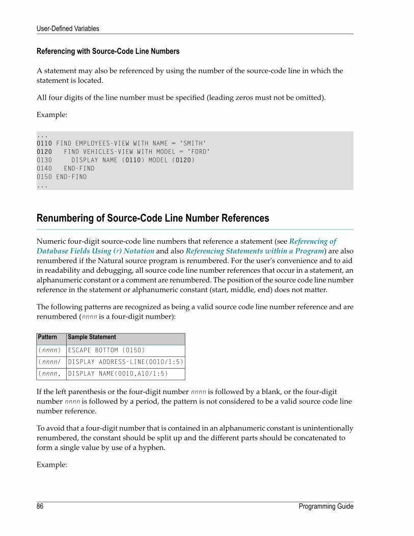
Referencing with Source-Code Line Numbers
A statement may also be referenced by using the number of the source-code line in which thestatement is located.
All four digits of the line number must be specified (leading zeros must not be omitted).
Example:
...0110 FIND EMPLOYEES-VIEW WITH NAME = 'SMITH'0120 FIND VEHICLES-VIEW WITH MODEL = 'FORD'0130 DISPLAY NAME (0110) MODEL (0120)0140 END-FIND0150 END-FIND...
Renumbering of Source-Code Line Number References
Numeric four-digit source-code line numbers that reference a statement (see Referencing ofDatabase Fields Using (r) Notation and also Referencing Statements within a Program) are alsorenumbered if the Natural source program is renumbered. For the user's convenience and to aidin readability and debugging, all source code line number references that occur in a statement, analphanumeric constant or a comment are renumbered. The position of the source code line numberreference in the statement or alphanumeric constant (start, middle, end) does not matter.
The following patterns are recognized as being a valid source code line number reference and arerenumbered (nnnn is a four-digit number):
Sample StatementPattern
ESCAPE BOTTOM (0150)(nnnn)
DISPLAY ADDRESS-LINE(0010/1:5)(nnnn/
DISPLAY NAME(0010,A10/1:5)(nnnn,
If the left parenthesis or the four-digit number nnnn is followed by a blank, or the four-digitnumber nnnn is followed by a period, the pattern is not considered to be a valid source code linenumber reference.
To avoid that a four-digit number that is contained in an alphanumeric constant is unintentionallyrenumbered, the constant should be split up and the different parts should be concatenated toform a single value by use of a hyphen.
Example:
Programming Guide86
User-Defined Variables

Z := 'XXXX (1234,00) YYYY'
should be replaced by
Z := 'XXXX (1234' - ',00) YYYY'
Format and Length of User-Defined Variables
Format and length of a user-defined variable are specified in parentheses after the variable name.
Fixed-length variables can be defined with the following formats and corresponding lengths.
For the definition of Format and Length in dynamic variables, seeDefinition ofDynamic Variables.
Internal Length (in Bytes)Definable LengthExplanationFormat
1 - 10737418241 - 1073741824 (1GB)AlphanumericA
1 - 10737418241 - 1073741824 (1GB)BinaryB
2-Attribute ControlC
4-DateD
4 or 84 or 8Floating PointF
1, 2 or 41 , 2 or 4IntegerI
1-LogicalL
1 - 291 - 29Numeric (unpacked)N
1 - 151 - 29Packed numericP
7-TimeT
2 - 10737418241 - 536870912 (0.5 GB)Unicode (UTF-16)U
Length can only be specified if format is specified. With some formats, the length need not be ex-plicitly specified (as shown in the table above).
For fields defined with format N or P, you can use decimal position notation in the form nn.m,where nn represents the number of positions before the decimal point, and m represents the numberof positions after the decimal point. The sum of the values of nn and mmust not exceed 29, andthe value of mmust not exceed 7.
Notes:
1. When a user-defined variable of format P is output with a DISPLAY, WRITE, or INPUT statement,Natural internally converts the format to N for the output.
87Programming Guide
User-Defined Variables

2. In reportingmode, if format and length are not specified for a user-defined variable, the defaultformat/length N7 will be used, unless this default assignment has been disabled by the pro-file/session parameter FS.
For a database field, the format/length as defined for the field in the data definitionmodule (DDM)apply. (In reporting mode, it is also possible to define in a program a different format/length fora database field.)
In structured mode, format and length may only be specified in a data area definition or with aDEFINE DATA statement.
Example of Format/Length Definition - Structured Mode:
DEFINE DATA LOCAL1 EMPLOY-VIEW VIEW OF EMPLOYEES
2 NAME2 FIRST-NAME
1 #NEW-SALARY (N6.2)END-DEFINE...FIND EMPLOY-VIEW ......COMPUTE #NEW-SALARY = ......
In reporting mode, format/length may be defined within the body of the program, if no DEFINEDATA statement is used.
Example of Format/Length Definition - Reporting Mode:
...
...FIND EMPLOYEES
... ... COMPUTE #NEW-SALARY(N6.2) = ...
...
Special Formats
In addition to the standard alphanumeric (A) and numeric (B, F, I, N, P) formats, Natural supportsthe following special formats:
■ Format C - Attribute Control■ Formats D - Date, and T - Time■ Format L - Logical
Programming Guide88
User-Defined Variables

■ Format: Handle
Format C - Attribute Control
A variable defined with format C may be used to assign attributes dynamically to a field used ina DISPLAY, INPUT, PRINT, PROCESS PAGE or WRITE statement.
For a variable of format C, no length can be specified. The variable is always assigned a length of2 bytes by Natural.
Example:
DEFINE DATA LOCAL1 #ATTR (C)1 #A (N5)END-DEFINE...MOVE (AD=I CD=RE) TO #ATTRINPUT #A (CV=#ATTR)...
For further information, see the session parameter CV.
Formats D - Date, and T - Time
Variables defined with formats D and T can be used for date and time arithmetic and display.Format D can contain date information only. Format T can contain date and time information; inotherwords, date information is a subset of time information. Time is counted in tenths of seconds.
For variables of formats D and T, no length can be specified. A variable with format D is alwaysassigned a length of 4 bytes (P6) and a variable of format T is always assigned a length of 7 bytes(P12) byNatural. If the profile parameter MAXYEAR is set to 9999, a variable with format D is alwaysassigned a length of 4 bytes (P7) and a variable of format T is always assigned a length of 7 bytes(P13) by Natural.
Example:
DEFINE DATA LOCAL1 #DAT1 (D)END-DEFINE*MOVE *DATX TO #DAT1ADD 7 TO #DAT1WRITE '=' #DAT1END
For further information, see the session parameter EM and the system variables *DATX and *TIMX.
89Programming Guide
User-Defined Variables
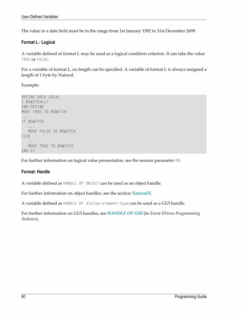
The value in a date field must be in the range from 1st January 1582 to 31st December 2699.
Format L - Logical
A variable defined of format L may be used as a logical condition criterion. It can take the valueTRUE or FALSE.
For a variable of format L, no length can be specified. A variable of format L is always assigned alength of 1 byte by Natural.
Example:
DEFINE DATA LOCAL1 #SWITCH(L)END-DEFINEMOVE TRUE TO #SWITCH...IF #SWITCH
...MOVE FALSE TO #SWITCH
ELSE...MOVE TRUE TO #SWITCH
END-IF
For further information on logical value presentation, see the session parameter EM.
Format: Handle
A variable defined as HANDLE OF OBJECT can be used as an object handle.
For further information on object handles, see the section NaturalX.
A variable defined as HANDLE OF dialog-element-type can be used as a GUI handle.
For further information on GUI handles, see HANDLE OF GUI (in Event-Driven ProgrammingTechnics).
Programming Guide90
User-Defined Variables
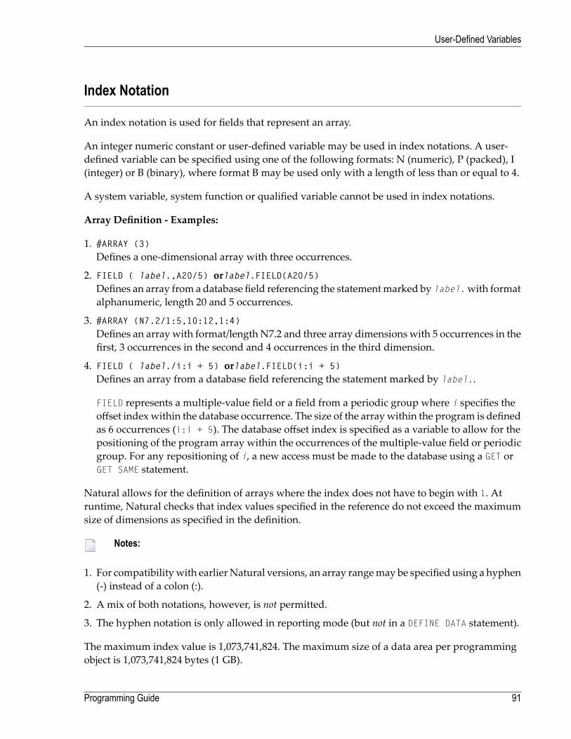
Index Notation
An index notation is used for fields that represent an array.
An integer numeric constant or user-defined variable may be used in index notations. A user-defined variable can be specified using one of the following formats: N (numeric), P (packed), I(integer) or B (binary), where format B may be used only with a length of less than or equal to 4.
A system variable, system function or qualified variable cannot be used in index notations.
Array Definition - Examples:
1. #ARRAY (3)Defines a one-dimensional array with three occurrences.
2. FIELD ( label.,A20/5) orlabel.FIELD(A20/5)Defines an array from a database field referencing the statementmarked by label.with formatalphanumeric, length 20 and 5 occurrences.
3. #ARRAY (N7.2/1:5,10:12,1:4)Defines an array with format/length N7.2 and three array dimensions with 5 occurrences in thefirst, 3 occurrences in the second and 4 occurrences in the third dimension.
4. FIELD ( label./i:i + 5) orlabel.FIELD(i:i + 5)Defines an array from a database field referencing the statement marked by label..
FIELD represents a multiple-value field or a field from a periodic group where i specifies theoffset indexwithin the database occurrence. The size of the arraywithin the program is definedas 6 occurrences (i:i + 5). The database offset index is specified as a variable to allow for thepositioning of the program array within the occurrences of the multiple-value field or periodicgroup. For any repositioning of i, a new access must be made to the database using a GET orGET SAME statement.
Natural allows for the definition of arrays where the index does not have to begin with 1. Atruntime, Natural checks that index values specified in the reference do not exceed the maximumsize of dimensions as specified in the definition.
Notes:
1. For compatibilitywith earlierNatural versions, an array rangemay be specified using a hyphen(-) instead of a colon (:).
2. A mix of both notations, however, is not permitted.
3. The hyphen notation is only allowed in reporting mode (but not in a DEFINE DATA statement).
The maximum index value is 1,073,741,824. The maximum size of a data area per programmingobject is 1,073,741,824 bytes (1 GB).
91Programming Guide
User-Defined Variables
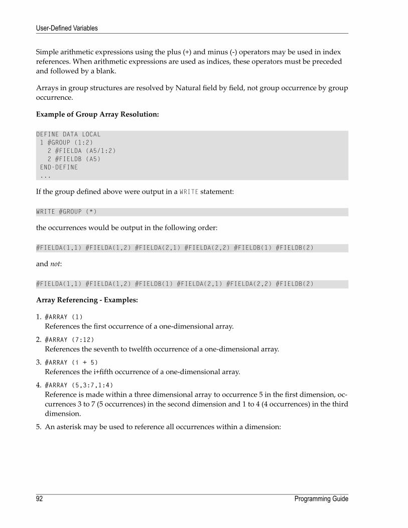
Simple arithmetic expressions using the plus (+) and minus (-) operators may be used in indexreferences. When arithmetic expressions are used as indices, these operators must be precededand followed by a blank.
Arrays in group structures are resolved by Natural field by field, not group occurrence by groupoccurrence.
Example of Group Array Resolution:
DEFINE DATA LOCAL1 #GROUP (1:2)2 #FIELDA (A5/1:2)2 #FIELDB (A5)
END-DEFINE...
If the group defined above were output in a WRITE statement:
WRITE #GROUP (*)
the occurrences would be output in the following order:
#FIELDA(1,1) #FIELDA(1,2) #FIELDA(2,1) #FIELDA(2,2) #FIELDB(1) #FIELDB(2)
and not:
#FIELDA(1,1) #FIELDA(1,2) #FIELDB(1) #FIELDA(2,1) #FIELDA(2,2) #FIELDB(2)
Array Referencing - Examples:
1. #ARRAY (1)References the first occurrence of a one-dimensional array.
2. #ARRAY (7:12)References the seventh to twelfth occurrence of a one-dimensional array.
3. #ARRAY (i + 5)References the i+fifth occurrence of a one-dimensional array.
4. #ARRAY (5,3:7,1:4)Reference is made within a three dimensional array to occurrence 5 in the first dimension, oc-currences 3 to 7 (5 occurrences) in the second dimension and 1 to 4 (4 occurrences) in the thirddimension.
5. An asterisk may be used to reference all occurrences within a dimension:
Programming Guide92
User-Defined Variables

DEFINE DATA LOCAL 1 #ARRAY1 (N5/1:4,1:4) 1 #ARRAY2 (N5/1:4,1:4) END-DEFINE ... ADD #ARRAY1 (2,*) TO #ARRAY2 (4,*) ... ↩
Using a Slash before an Array Occurrence
If a variable name is followed by a 4-digit number enclosed in parentheses, Natural interprets thisnumber as a line-number reference to a statement. Therefore a 4-digit array occurrence must bepreceded by a slash (/) to indicate that it is an array occurrence; for example:
#ARRAY(/1000)
not:
#ARRAY(1000)
because the latter would be interpreted as a reference to source code line 1000.
If an index variable name could bemisinterpreted as a format/length specification, a slash (/) mustbe used to indicate that an index is being specified. If, for example, the occurrence of an array isdefined by the value of the variable N7, the occurrence must be specified as:
#ARRAY (/N7)
not:
#ARRAY (N7)
because the latter would be misinterpreted as the definition of a 7-byte numeric field.
Referencing a Database Array
The following topics are covered below:
■ Referencing Multiple-Value Fields and Periodic-Group Fields■ Referencing Arrays Defined with Constants■ Referencing Arrays Defined with Variables■ Referencing Multiple-Defined Arrays
Note: Before executing the following example programs, please run the program INDEXTST
in the library SYSEXPG to create an example record that uses 10 different language codes.
93Programming Guide
User-Defined Variables

Referencing Multiple-Value Fields and Periodic-Group Fields
Amultiple-value field or periodic-group fieldwithin a view/DDMmay be defined and referencedusing various index notations.
For example, the first to tenth values and the Ith to Ith+10 values of the same multiple-valuefield/periodic-group field of a database record:
DEFINE DATA LOCAL1 I (I2)1 EMPLOY-VIEW VIEW OF EMPLOYEES
2 LANG (1:10)2 LANG (I:I+10)
END-DEFINE
or:
RESET I (I2)...READ EMPLOYEESOBTAIN LANG(1:10) LANG(I:I+10)
Notes:
1. The same lower bound index may only be used once per array (this applies to constant indexesas well as variable indexes).
2. For an array definition using a variable index, the lower bound must be specified using thevariable by itself, and the upper boundmust be specified using the same variable plus a constant.
Referencing Arrays Defined with Constants
An array definedwith constants may be referenced using either constants or variables. The upperbound of the array cannot be exceeded. The upper boundwill be checked byNatural at compilationtime if a constant is used.
Reporting Mode Example:
** Example 'INDEX1R': Array definition with constants (reporting mode)************************************************************************READ (1) EMPLOYEES WITH NAME = 'WINTER' WHERE CITY = 'LONDON'
OBTAIN LANG (1:10)/*WRITE 'LANG(1:10):' LANG (1:10) //WRITE 'LANG(1) :' LANG (1) / 'LANG(5:9) :' LANG (5:9)
LOOP*END
Programming Guide94
User-Defined Variables
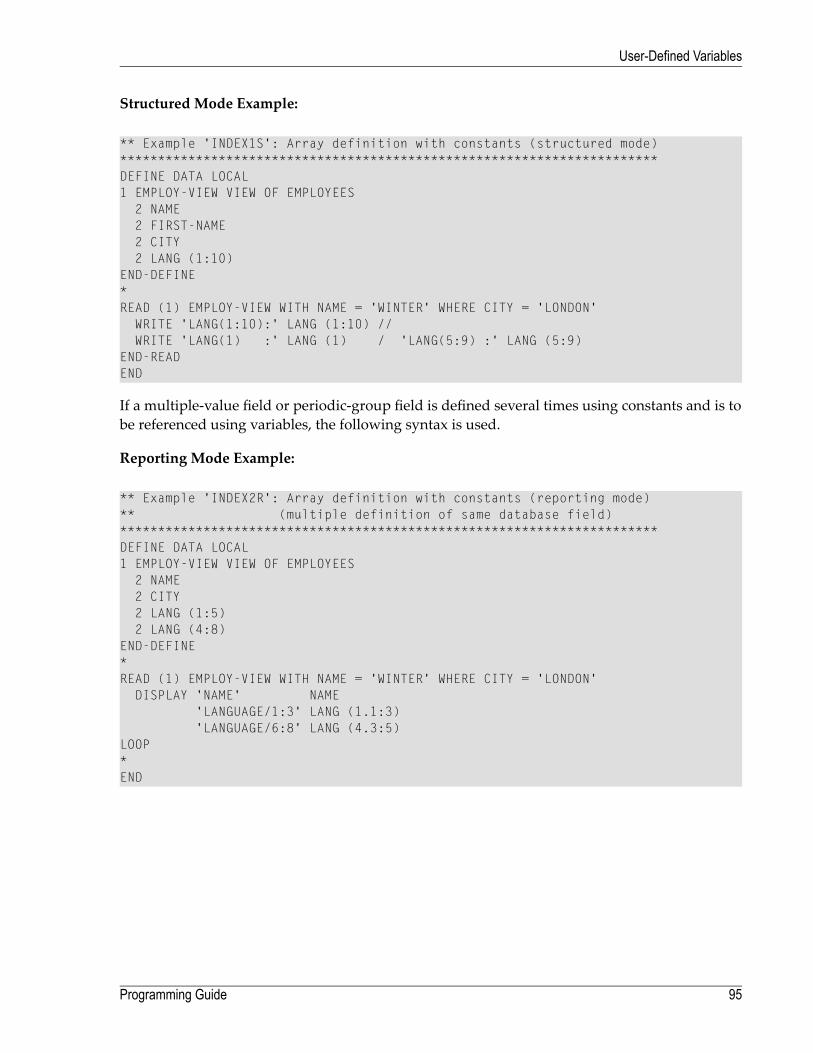
Structured Mode Example:
** Example 'INDEX1S': Array definition with constants (structured mode)***********************************************************************DEFINE DATA LOCAL1 EMPLOY-VIEW VIEW OF EMPLOYEES
2 NAME2 FIRST-NAME2 CITY2 LANG (1:10)
END-DEFINE*READ (1) EMPLOY-VIEW WITH NAME = 'WINTER' WHERE CITY = 'LONDON'
WRITE 'LANG(1:10):' LANG (1:10) //WRITE 'LANG(1) :' LANG (1) / 'LANG(5:9) :' LANG (5:9)
END-READEND
If a multiple-value field or periodic-group field is defined several times using constants and is tobe referenced using variables, the following syntax is used.
Reporting Mode Example:
** Example 'INDEX2R': Array definition with constants (reporting mode)** (multiple definition of same database field)***********************************************************************DEFINE DATA LOCAL1 EMPLOY-VIEW VIEW OF EMPLOYEES
2 NAME2 CITY2 LANG (1:5)2 LANG (4:8)
END-DEFINE*READ (1) EMPLOY-VIEW WITH NAME = 'WINTER' WHERE CITY = 'LONDON'
DISPLAY 'NAME' NAME'LANGUAGE/1:3' LANG (1.1:3)'LANGUAGE/6:8' LANG (4.3:5)
LOOP*END
95Programming Guide
User-Defined Variables
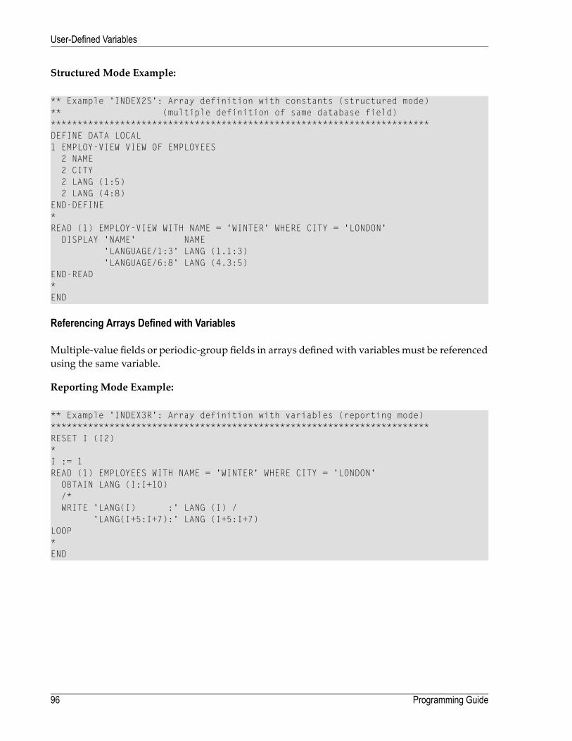
Structured Mode Example:
** Example 'INDEX2S': Array definition with constants (structured mode)** (multiple definition of same database field)***********************************************************************DEFINE DATA LOCAL1 EMPLOY-VIEW VIEW OF EMPLOYEES
2 NAME2 CITY2 LANG (1:5)2 LANG (4:8)
END-DEFINE*READ (1) EMPLOY-VIEW WITH NAME = 'WINTER' WHERE CITY = 'LONDON'
DISPLAY 'NAME' NAME'LANGUAGE/1:3' LANG (1.1:3)'LANGUAGE/6:8' LANG (4.3:5)
END-READ*END
Referencing Arrays Defined with Variables
Multiple-value fields or periodic-group fields in arrays definedwith variables must be referencedusing the same variable.
Reporting Mode Example:
** Example 'INDEX3R': Array definition with variables (reporting mode)***********************************************************************RESET I (I2)*I := 1READ (1) EMPLOYEES WITH NAME = 'WINTER' WHERE CITY = 'LONDON'
OBTAIN LANG (I:I+10)/*WRITE 'LANG(I) :' LANG (I) /
'LANG(I+5:I+7):' LANG (I+5:I+7)LOOP*END
Programming Guide96
User-Defined Variables

Structured Mode Example:
** Example 'INDEX3S': Array definition with variables (structured mode)***********************************************************************DEFINE DATA LOCAL1 I (I2)*1 EMPLOY-VIEW VIEW OF EMPLOYEES
2 NAME2 CITY2 LANG (I:I+10)
END-DEFINE*I := 1READ (1) EMPLOY-VIEW WITH NAME = 'WINTER' WHERE CITY = 'LONDON'
WRITE 'LANG(I) :' LANG (I) /'LANG(I+5:I+7):' LANG (I+5:I+7)
END-READEND
If a different index is to be used, an unambiguous reference to the first encountered definition ofthe array with variable index must be made. This is done by qualifying the index expression asshown below.
Reporting Mode Example:
** Example 'INDEX4R': Array definition with variables (reporting mode)***********************************************************************RESET I (I2) J (I2)*I := 2J := 3*READ (1) EMPLOYEES WITH NAME = 'WINTER' WHERE CITY = 'LONDON'
OBTAIN LANG (I:I+10)/*WRITE 'LANG(I.J) :' LANG (I.J) /
'LANG(I.1:5):' LANG (I.1:5)LOOP*END
97Programming Guide
User-Defined Variables

Structured Mode Example:
** Example 'INDEX4S': Array definition with variables (structured mode)***********************************************************************DEFINE DATA LOCAL1 I (I2)1 J (I2)1 EMPLOY-VIEW VIEW OF EMPLOYEES
2 NAME2 CITY2 LANG (I:I+10)
END-DEFINE*I := 2J := 3READ (1) EMPLOY-VIEW WITH NAME = 'WINTER' WHERE CITY = 'LONDON'
WRITE 'LANG(I.J) :' LANG (I.J) /'LANG(I.1:5):' LANG (I.1:5)
END-READEND
The expression I. is used to create an unambiguous reference to the array definition and “positions”to the first value within the read array range (LANG(I.1:5)).
The current content of I at the time of the database access determines the starting occurrence ofthe database array.
Referencing Multiple-Defined Arrays
For multiple-defined arrays, a reference with qualification of the index expression is usually ne-cessary to ensure an unambiguous reference to the desired array range.
Reporting Mode Example:
** Example 'INDEX5R': Array definition with constants (reporting mode)** (multiple definition of same database field)***********************************************************************DEFINE DATA LOCAL /* For reporting mode programs1 EMPLOY-VIEW VIEW OF EMPLOYEES /* DEFINE DATA is recommended
2 NAME /* to use multiple definitions2 CITY /* of same database field2 LANG (1:10)2 LANG (5:10)
*1 I (I2)1 J (I2)END-DEFINE*I := 1J := 2
Programming Guide98
User-Defined Variables

*READ (1) EMPLOY-VIEW WITH NAME = 'WINTER' WHERE CITY = 'LONDON'
WRITE 'LANG(1.1:10) :' LANG (1.1:10) /'LANG(1.I:I+2):' LANG (1.I:I+2) //
WRITE 'LANG(5.1:5) :' LANG (5.1:5) /'LANG(5.J) :' LANG (5.J)
LOOPEND
Structured Mode Example:
** Example 'INDEX5S': Array definition with constants (structured mode)** (multiple definition of same database field)***********************************************************************DEFINE DATA LOCAL1 EMPLOY-VIEW VIEW OF EMPLOYEES
2 NAME2 CITY2 LANG (1:10)2 LANG (5:10)
*1 I (I2)1 J (I2)END-DEFINE**I := 1J := 2*READ (1) EMPLOY-VIEW WITH NAME = 'WINTER' WHERE CITY = 'LONDON'
WRITE 'LANG(1.1:10) :' LANG (1.1:10) /'LANG(1.I:I+2):' LANG (1.I:I+2) //
WRITE 'LANG(5.1:5) :' LANG (5.1:5) /'LANG(5.J) :' LANG (5.J)
END-READEND
A similar syntax is also used if multiple-value fields or periodic-group fields are defined usingindex variables.
Reporting Mode Example:
** Example 'INDEX6R': Array definition with variables (reporting mode)** (multiple definition of same database field)***********************************************************************DEFINE DATA LOCAL1 I (I2) INIT <1>1 J (I2) INIT <2>1 N (I2) INIT <1>1 EMPLOY-VIEW VIEW OF EMPLOYEES /* For reporting mode programs
2 NAME /* DEFINE DATA is recommended
99Programming Guide
User-Defined Variables
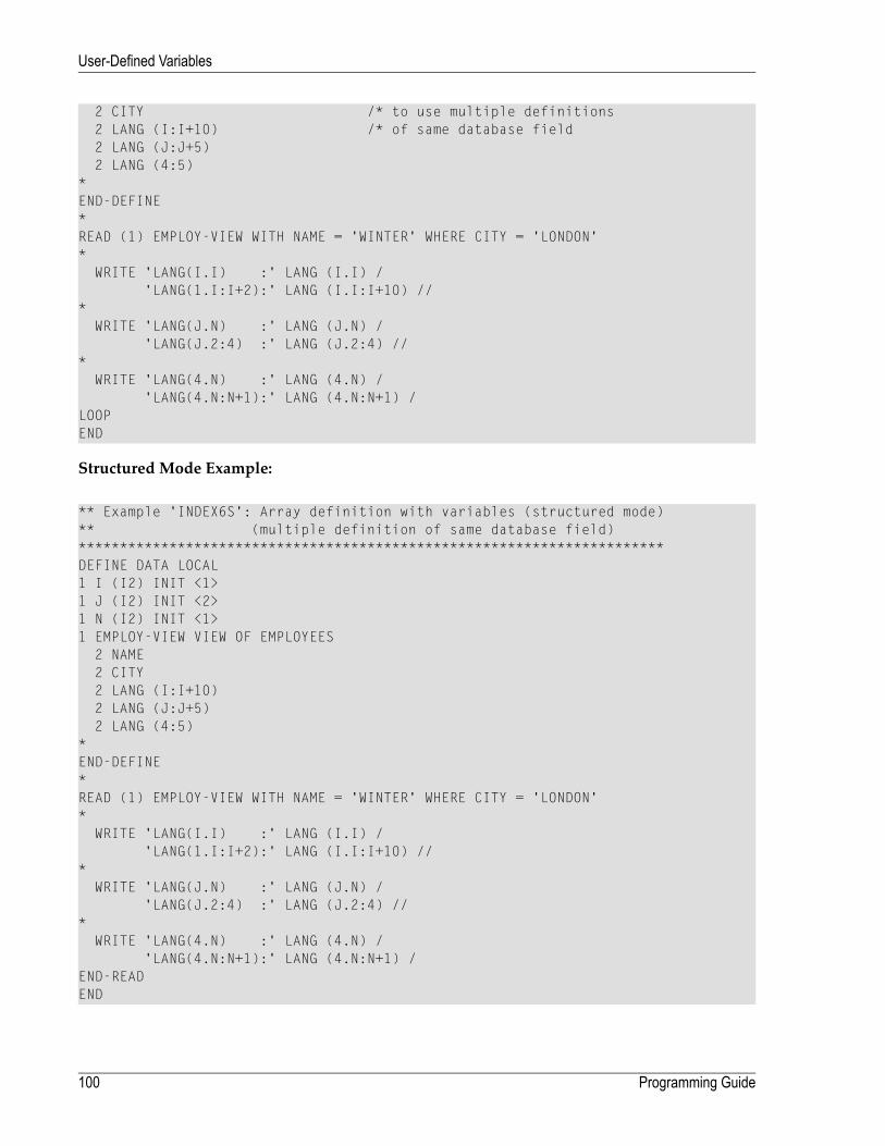
2 CITY /* to use multiple definitions2 LANG (I:I+10) /* of same database field2 LANG (J:J+5)2 LANG (4:5)
*END-DEFINE*READ (1) EMPLOY-VIEW WITH NAME = 'WINTER' WHERE CITY = 'LONDON'*
WRITE 'LANG(I.I) :' LANG (I.I) /'LANG(1.I:I+2):' LANG (I.I:I+10) //
*WRITE 'LANG(J.N) :' LANG (J.N) /
'LANG(J.2:4) :' LANG (J.2:4) //*
WRITE 'LANG(4.N) :' LANG (4.N) /'LANG(4.N:N+1):' LANG (4.N:N+1) /
LOOPEND
Structured Mode Example:
** Example 'INDEX6S': Array definition with variables (structured mode)** (multiple definition of same database field)***********************************************************************DEFINE DATA LOCAL1 I (I2) INIT <1>1 J (I2) INIT <2>1 N (I2) INIT <1>1 EMPLOY-VIEW VIEW OF EMPLOYEES
2 NAME2 CITY2 LANG (I:I+10)2 LANG (J:J+5)2 LANG (4:5)
*END-DEFINE*READ (1) EMPLOY-VIEW WITH NAME = 'WINTER' WHERE CITY = 'LONDON'*
WRITE 'LANG(I.I) :' LANG (I.I) /'LANG(1.I:I+2):' LANG (I.I:I+10) //
*WRITE 'LANG(J.N) :' LANG (J.N) /
'LANG(J.2:4) :' LANG (J.2:4) //*
WRITE 'LANG(4.N) :' LANG (4.N) /'LANG(4.N:N+1):' LANG (4.N:N+1) /
END-READEND
Programming Guide100
User-Defined Variables
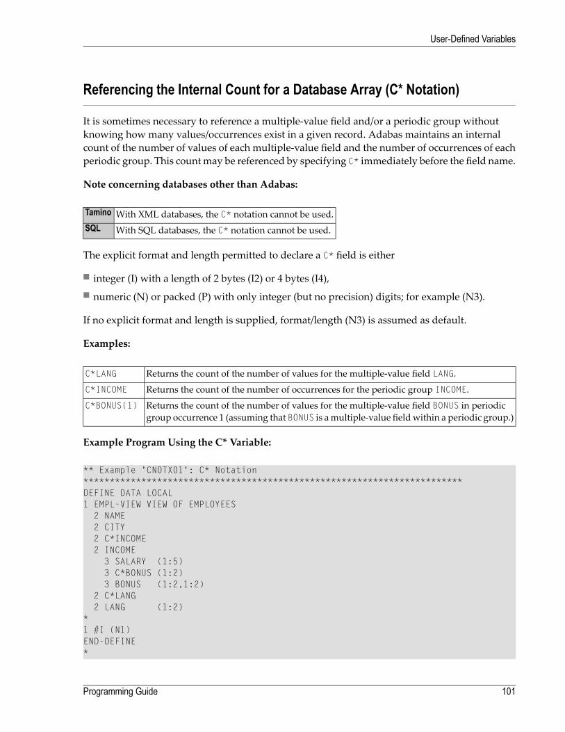
Referencing the Internal Count for a Database Array (C* Notation)
It is sometimes necessary to reference a multiple-value field and/or a periodic group withoutknowing how many values/occurrences exist in a given record. Adabas maintains an internalcount of the number of values of each multiple-value field and the number of occurrences of eachperiodic group. This countmay be referenced by specifying C* immediately before the field name.
Note concerning databases other than Adabas:
With XML databases, the C* notation cannot be used.Tamino
With SQL databases, the C* notation cannot be used.SQL
The explicit format and length permitted to declare a C* field is either
■ integer (I) with a length of 2 bytes (I2) or 4 bytes (I4),■ numeric (N) or packed (P) with only integer (but no precision) digits; for example (N3).
If no explicit format and length is supplied, format/length (N3) is assumed as default.
Examples:
Returns the count of the number of values for the multiple-value field LANG.C*LANG
Returns the count of the number of occurrences for the periodic group INCOME.C*INCOME
Returns the count of the number of values for the multiple-value field BONUS in periodicgroup occurrence 1 (assuming that BONUS is amultiple-value fieldwithin a periodic group.)
C*BONUS(1)
Example Program Using the C* Variable:
** Example 'CNOTX01': C* Notation************************************************************************DEFINE DATA LOCAL1 EMPL-VIEW VIEW OF EMPLOYEES
2 NAME2 CITY2 C*INCOME2 INCOME
3 SALARY (1:5)3 C*BONUS (1:2)3 BONUS (1:2,1:2)
2 C*LANG2 LANG (1:2)
*1 #I (N1)END-DEFINE*
101Programming Guide
User-Defined Variables

LIMIT 2READ EMPL-VIEW BY CITY
/*WRITE NOTITLE 'NAME:' NAME /
'NUMBER OF LANGUAGES SPOKEN:' C*LANG 5X'LANGUAGE 1:' LANG (1) 5X'LANGUAGE 2:' LANG (2)
/*WRITE 'SALARY DATA:'FOR #I FROM 1 TO C*INCOME
WRITE 'SALARY' #I SALARY (1.#I)END-FOR/*WRITE 'THIS YEAR BONUS:' C*BONUS(1) BONUS (1,1) BONUS (1,2)
/ 'LAST YEAR BONUS:' C*BONUS(2) BONUS (2,1) BONUS (2,2)SKIP 1
END-READEND
Output of Program CNOTX01:
NAME: SENKONUMBER OF LANGUAGES SPOKEN: 1 LANGUAGE 1: ENG LANGUAGE 2:SALARY DATA:SALARY 1 36225SALARY 2 29900SALARY 3 28100SALARY 4 26600SALARY 5 25200THIS YEAR BONUS: 0 0 0LAST YEAR BONUS: 0 0 0
NAME: CANALENUMBER OF LANGUAGES SPOKEN: 2 LANGUAGE 1: FRE LANGUAGE 2: ENGSALARY DATA:SALARY 1 202285THIS YEAR BONUS: 1 23000 0LAST YEAR BONUS: 0 0 0
C* for Multiple-Value Fields Within Periodic Groups
For a multiple-value field within a periodic group, you can also define a C* variable with an indexrange specification.
The following examples use the multiple-value field BONUS, which is part of the periodic groupINCOME. All three examples yield the same result.
Programming Guide102
User-Defined Variables
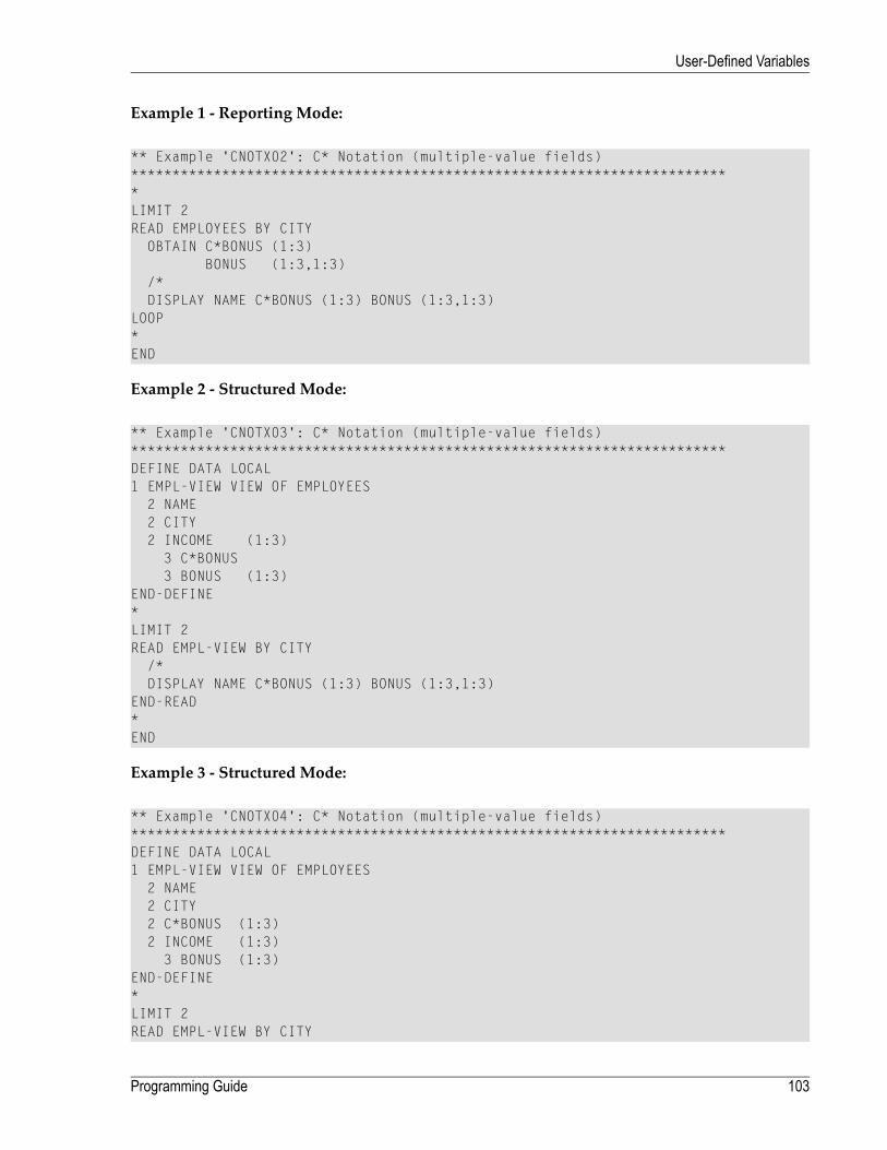
Example 1 - Reporting Mode:
** Example 'CNOTX02': C* Notation (multiple-value fields)*************************************************************************LIMIT 2READ EMPLOYEES BY CITY
OBTAIN C*BONUS (1:3)BONUS (1:3,1:3)
/*DISPLAY NAME C*BONUS (1:3) BONUS (1:3,1:3)
LOOP*END
Example 2 - Structured Mode:
** Example 'CNOTX03': C* Notation (multiple-value fields)************************************************************************DEFINE DATA LOCAL1 EMPL-VIEW VIEW OF EMPLOYEES
2 NAME2 CITY2 INCOME (1:3)
3 C*BONUS3 BONUS (1:3)
END-DEFINE*LIMIT 2READ EMPL-VIEW BY CITY
/*DISPLAY NAME C*BONUS (1:3) BONUS (1:3,1:3)
END-READ*END
Example 3 - Structured Mode:
** Example 'CNOTX04': C* Notation (multiple-value fields)************************************************************************DEFINE DATA LOCAL1 EMPL-VIEW VIEW OF EMPLOYEES
2 NAME2 CITY2 C*BONUS (1:3)2 INCOME (1:3)
3 BONUS (1:3)END-DEFINE*LIMIT 2READ EMPL-VIEW BY CITY
103Programming Guide
User-Defined Variables

/*DISPLAY NAME C*BONUS (*) BONUS (*,*)
END-READ*END
Caution: As the Adabas format buffer does not permit ranges for count fields, they aregenerated as individual fields; therefore a C* index range for a large array may cause anAdabas format buffer overflow.
Qualifying Data Structures
To identify a field when referencing it, you may qualify the field; that is, before the field name,you specify the name of the level-1 data element in which the field is located and a period.
If a field cannot be identified uniquely by its name (for example, if the same field name is used inmultiple groups/views), you must qualify the field when you reference it.
The combination of level-1 data element and field name must be unique.
Example:
DEFINE DATA LOCAL1 FULL-NAME
2 LAST-NAME (A20)2 FIRST-NAME (A15)
1 OUTPUT-NAME2 LAST-NAME (A20)2 FIRST-NAME (A15)
END-DEFINE...MOVE FULL-NAME.LAST-NAME TO OUTPUT-NAME.LAST-NAME...
The qualifier must be a level-1 data element.
Example:
DEFINE DATA LOCAL1 GROUP1
2 SUB-GROUP3 FIELD1 (A15)3 FIELD2 (A15)
END-DEFINE...MOVE 'ABC' TO GROUP1.FIELD1...
Programming Guide104
User-Defined Variables

Qualifying a Database Field:
If you use the same name for a user-defined variable and a database field (which you should notdo anyway), you must qualify the database field when you want to reference it
Caution: If you do not qualify the database field when you want to reference it, the user-defined variable will be referenced instead.
Examples of User-Defined Variables
DEFINE DATA LOCAL 1 #A1 (A10) /* Alphanumeric, 10 positions. 1 #A2 (B4) /* Binary, 4 positions. 1 #A3 (P4) /* Packed numeric, 4 positions and 1 sign position. 1 #A4 (N7.2) /* Unpacked numeric, /* 7 positions before and 2 after decimal point. 1 #A5 (N7.) /* Invalid definition!!! 1 #A6 (P7.2) /* Packed numeric, 7 positions before and 2 after decimal point /* and 1 sign position. 1 #INT1 (I1) /* Integer, 1 byte. 1 #INT2 (I2) /* Integer, 2 bytes. 1 #INT3 (I3) /* Invalid definition!!! 1 #INT4 (I4) /* Integer, 4 bytes. 1 #INT5 (I5) /* Invalid definition!!! 1 #FLT4 (F4) /* Floating point, 4 bytes. 1 #FLT8 (F8) /* Floating point, 8 bytes. 1 #FLT2 (F2) /* Invalid definition!!! 1 #DATE (D) /* Date (internal format/length P6). 1 #TIME (T) /* Time (internal format/length P12). 1 #SWITCH (L) /* Logical, 1 byte (TRUE or FALSE). /*END-DEFINE ↩
105Programming Guide
User-Defined Variables

106

15 Function Call
■ Calling User-Defined Functions ........................................................................................................ 108■ Function Result ............................................................................................................................. 109■ Evaluation Sequence ..................................................................................................................... 109■ Restrictions .................................................................................................................................. 109■ Syntax Description ......................................................................................................................... 110■ Example ...................................................................................................................................... 114
107
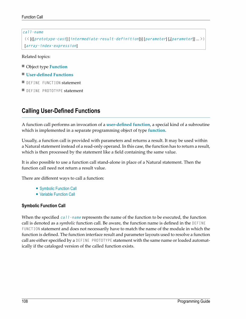
call-name
(< [([prototype-cast] [intermediate-result-definition])] [parameter] [,[parameter]] ... >)
[array-index-expression]
Related topics:
■ Object type Function■ User-defined Functions■ DEFINE FUNCTION statement■ DEFINE PROTOTYPE statement
Calling User-Defined Functions
A function call performs an invocation of a user-defined function, a special kind of a subroutinewhich is implemented in a separate programming object of type function.
Usually, a function call is provided with parameters and returns a result. It may be used withinaNatural statement instead of a read-only operand. In this case, the function has to return a result,which is then processed by the statement like a field containing the same value.
It is also possible to use a function call stand-alone in place of a Natural statement. Then thefunction call need not return a result value.
There are different ways to call a function:
■ Symbolic Function Call■ Variable Function Call
Symbolic Function Call
When the specified call-name represents the name of the function to be executed, the functioncall is denoted as a symbolic function call. Be aware, the function name is defined in the DEFINEFUNCTION statement and does not necessarily have to match the name of the module in which thefunction is defined. The function interface result and parameter layouts used to resolve a functioncall are either specified by a DEFINE PROTOTYPE statement with the same name or loaded automat-ically if the cataloged version of the called function exists.
Programming Guide108
Function Call

Variable Function Call
A function can also be called in an indirect form, denoted as a variable function call. In this case,the specified call-name is an alphanumeric variable, which contains the name of the called functionat execution time. This variable has to be referenced in a prototype definition (DEFINE PROTOTYPEstatement) in conjunction with the keyword VARIABLE. If this prototype does not contain the rightresult layout or parameter layout, another prototype can be assigned with the (PT=) option.
Function Result
According to the function definition, a function call may return a single result field. This can be ascalar value or an array field, which is processed like a temporary field in the statement wherethe function call is embedded. If the result is an array, the function call must be immediately fol-lowed by an array-index-expression addressing the required occurrences.
For example, to access the first occurrence of the array returned:
#FCT(<#A,#B>)(1)
Evaluation Sequence
If a single or multiple function calls are used within a statement, the evaluation of all functions isperformed in a separate step before the statement execution will be started. The function calls areexecuted in the same order in which they appear in the statement.
Restrictions
Function calls are not allowed in the following situations:
■ in positions where the operand value is changed by the Natural statement (for example, MOVE1 TO #FCT(<..>) );
■ in a DEFINE DATA statement;■ in a database access statement (READ, FIND, SELECT, UPDATE, STORE, etc.);■ in an AT BREAK or IF BREAK statement;■ as an argument of Natural system functions (AVER, SUM, *TRIM, etc.);■ as an array index notation;■ as a parameter of a function call.
109Programming Guide
Function Call

If a function call is used in an INPUT statement, the return value will be treated like a constantvalue. This leads to an automatic assignment of attribute (AD=O) to make this field write-protected(for output only).
Syntax Description
A function call may consist of the following syntax elements:
■ call-name■ prototype-cast■ intermediate-result-definition■ Parameter(s)■ array-index-expression
call-name
function-name
variable-name
Operand Definition Table:
Dynamic DefinitionReferencing PermittedPossible FormatsPossible StructureOperand
noyesUAASvariable-name
Syntax Element Description:
DescriptionSyntax Element
Function Name:function-name
function-name is the name of the function to be called. Be aware, the function nameis defined in the DEFINE FUNCTION statement and does not necessarily have to matchthe name of the module in which the function is defined. If a prototype with the samename has already been defined before, this prototype is used to pick up the functioninterface; that is, the result layout definition and the required parameters.
Variable Function Name:variable-name
variable-name is the name of the variable containing the real name of the function tobe called at runtime. In order to declare the call name as a variable name, a prototypewith the same name, which is classified with keyword VARIABLE, must be definedbefore.
Programming Guide110
Function Call
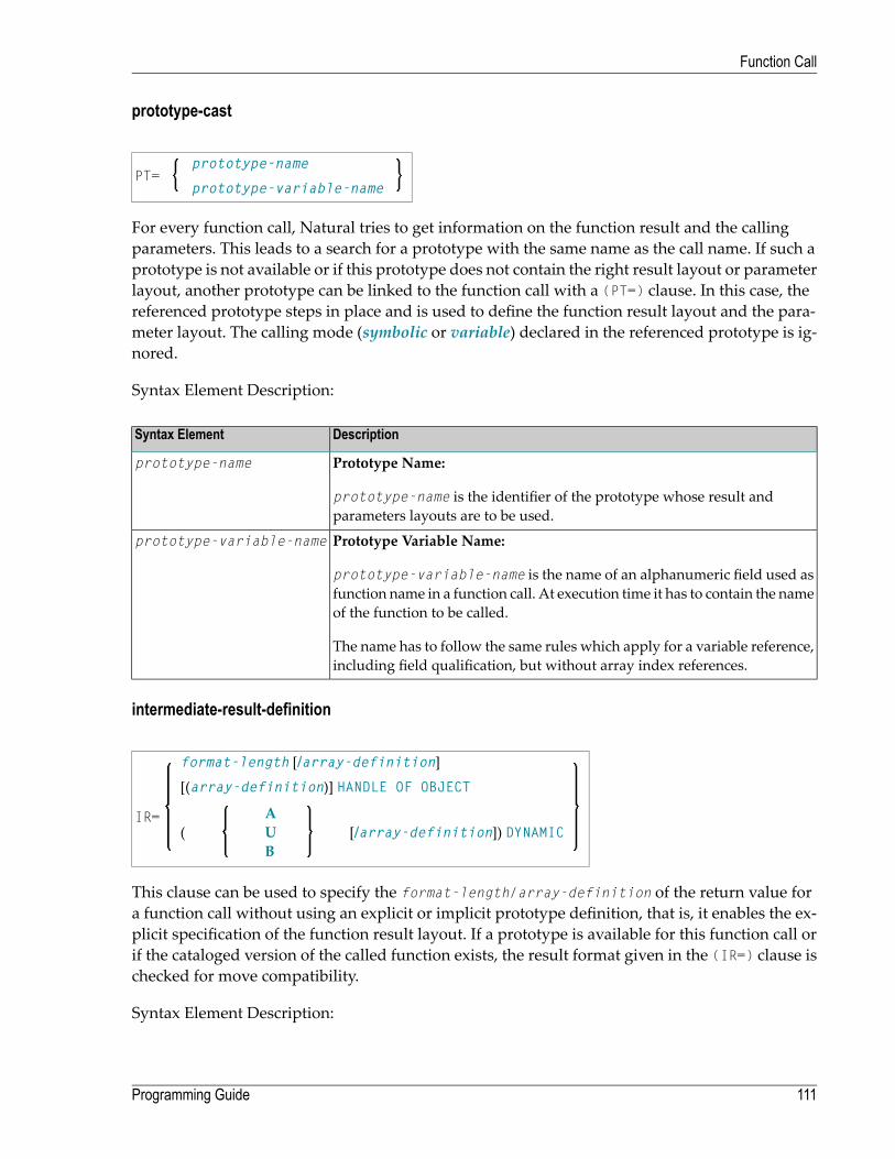
prototype-cast
prototype-namePT=
prototype-variable-name
For every function call, Natural tries to get information on the function result and the callingparameters. This leads to a search for a prototype with the same name as the call name. If such aprototype is not available or if this prototype does not contain the right result layout or parameterlayout, another prototype can be linked to the function call with a (PT=) clause. In this case, thereferenced prototype steps in place and is used to define the function result layout and the para-meter layout. The calling mode (symbolic or variable) declared in the referenced prototype is ig-nored.
Syntax Element Description:
DescriptionSyntax Element
Prototype Name:prototype-name
prototype-name is the identifier of the prototype whose result andparameters layouts are to be used.
Prototype Variable Name:prototype-variable-name
prototype-variable-name is the name of an alphanumeric field used asfunction name in a function call. At execution time it has to contain the nameof the function to be called.
The name has to follow the same rules which apply for a variable reference,including field qualification, but without array index references.
intermediate-result-definition
format-length [/array-definition]
IR=
[(array-definition)] HANDLE OF OBJECT
[/array-definition]) DYNAMIC(AUB
This clause can be used to specify the format-length/array-definition of the return value fora function call without using an explicit or implicit prototype definition, that is, it enables the ex-plicit specification of the function result layout. If a prototype is available for this function call orif the cataloged version of the called function exists, the result format given in the (IR=) clause ischecked for move compatibility.
Syntax Element Description:
111Programming Guide
Function Call

DescriptionSyntax Element
Format/Length Definition:format-length
The format and length of the field.
For information on format/length definition of user-defined variables, see Formatand Length of User-Defined Variables.
Array Dimension Definition:array-definition
With an array-definition, you define the lower and upper bounds of thedimensions in an array definition.
See Array Dimension Definition in the Statements documentation.
Handle of Object:HANDLE OF OBJECT
Used in conjunction with NaturalX.
For further information, see NaturalX in the Programming Guide.
Data Format:A, B or U
Possible formats are alphanumeric, binary or Unicode for dynamic variables.
Dynamic Variable:DYNAMIC
A field may be defined as DYNAMIC.
For further information onprocessingdynamic variables, see Introduction toDynamicVariables and Fields.
Parameter(s)
Parameters are the data values passed to the function. They can be provided as a constant valueor a variable, depending onwhat is defined in the DEFINE DATA PARAMETER section of the functiondefinition. The semantic and syntactic rules which apply to the function parameters are the sameas described in the parameters section of subprograms; see Parameters in the description of theCALLNAT statement.
nX
MO )(AD=operand
A
Operand Definition Table:
Programming Guide112
Function Call

Dynamic DefinitionReferencingPermitted
Possible FormatsPossible StructureOperand
noyesOGCLTDBFIPNAGASCoperand
Syntax Element Description:
DescriptionSyntaxElement
Parameters to be Skipped:nX
With the notation nX you can specify that the next n parameters are to be skipped (for example,1X to skip the next parameter, or 3X to skip the next three parameters); this means that for the nextn parameters no values are passed to the function.
A parameter that is to be skipped must be defined with the keyword OPTIONAL in the function'sDEFINE DATA PARAMETER statement. OPTIONALmeans that a value can - but need not - be passedfrom the invoking object to such a parameter.
Attribute Definition:AD=
If operand is a variable, you can mark it in one of the following ways:
Non-modifiable:AD=O
See session parameter AD=O.
Note: Internally, AD=O is processed in the same way asBY VALUE (see the sectionparameter-data-definition in the description ofthe DEFINE DATA statement).
Modifiable:AD=M
See session parameter AD=M.
This is the default setting.
Input only:AD=A
See session parameter AD=A.
Note: If operand is a constant, the attribute definition AD cannot be explicitly specified. Forconstants, AD=O always applies.
113Programming Guide
Function Call

array-index-expression
If the result returned by the function call is an array, an index notationmust be provided to addressthe demanded array occurrences.
For details, refer to Index Notation in User-Defined Variables in the Programming Guide.
Example
The example FUNCEX01 uses the functions F#ADDITION, F#CHAR, F#EVEN and F#TEXT, which aredefined in the sample functions FUNCEX02, FUNCEX03, FUNCEX04 and FUNCEX05.
** Example 'FUNCEX01': Function call (Program)************************************************************************DEFINE DATA LOCAL
1 #NUM (I2) INIT <5>1 #A (I2) INIT <1>1 #B (I2) INIT <2>1 #C (I2) INIT <3>1 #CHAR (A1) INIT <'A'>
END-DEFINE*IF #NUM = F#ADDITION(<#A,#B,#C>) /* Function with three parameters.
WRITE 'Sum of #A,#B,#C' #NUMELSE
IF #NUM = F#ADDITION(<1X,#B,#C>) /* Function with optional parameters.WRITE 'Sum of #B,#C' #NUM
END-IFEND-IF*DECIDE ON FIRST #CHAR
VALUE F#CHAR (<>)(1) /* Function with result array.WRITE 'Character A found'
VALUE F#CHAR (<>)(2)WRITE 'Character B found'
NONEIGNORE
END-DECIDE*IF F#EVEN(<#B>) /* Function with logical result value.
WRITE #B 'is an even number'END-IF*F#TEXT(<'Hello', '*'>) /* Function used as a statement.*WRITE F#TEXT(<(IR=A12) 'Good'>) /* Function with intermediate result.*END
Programming Guide114
Function Call

The function F#ADDITION is defined in the sample function FUNCEX02 in library SYSEXPG.
** Example 'FUNCEX02': Function call (Function)************************************************************************DEFINE FUNCTION F#ADDITION
RETURNS (I2)DEFINE DATA PARAMETER
1 #PARM1 (I2) OPTIONAL1 #PARM2 (I2) OPTIONAL1 #PARM3 (I2) OPTIONAL
END-DEFINE /* RESET F#ADDITION IF #PARM1 SPECIFIED F#ADDITION := F#ADDITION + #PARM1 ↩ END-IF IF #PARM2 SPECIFIED F#ADDITION := F#ADDITION + #PARM2 ↩ END-IF IF #PARM3 SPECIFIED F#ADDITION := F#ADDITION + #PARM3 ↩ END-IF /* END-FUNCTION * END ↩
The function F#CHAR is defined in the example function FUNCEX03 in library SYSEXPG.
** Example 'FUNCEX03': Function call (Function)************************************************************************DEFINE FUNCTION F#CHAR
RETURNS (A1/1:2)/*F#CHAR(1) := 'A'F#CHAR(2) := 'B'/*
END-FUNCTION * END ↩
The function F#EVEN is defined in the example function FUNCEX04 in library SYSEXPG.
115Programming Guide
Function Call

** Example 'FUNCEX04': Function call (Function)************************************************************************DEFINE FUNCTION F#EVEN
RETURNS (L)DEFINE DATAPARAMETER
1 #NUM (N4) BY VALUELOCAL
1 #REST (I2)END-DEFINE/*DIVIDE 2 INTO #NUM REMAINDER #REST/*IF #REST = 0
F#EVEN := TRUEELSE
F#EVEN := FALSEEND-IF/*
END-FUNCTION * END ↩
The function F#TEXT is defined in the sample function FUNCEX05 in library SYSEXPG.
** Example 'FUNCEX05': Function call (Function)************************************************************************DEFINE FUNCTION F#TEXT
RETURNS (A20) BY VALUEDEFINE DATAPARAMETER
1 #TEXT1 (A5) BY VALUE1 #TEXT2 (A1) BY VALUE OPTIONAL
LOCAL1 #FRAME (A3)
END-DEFINE/*IF #TEXT2 SPECIFIED
MOVE ALL #TEXT2 TO #FRAME/*COMPRESS #FRAME #TEXT1 'world' #FRAME INTO F#TEXT/*WRITE F#TEXT
ELSECOMPRESS #TEXT1 'morning' INTO F#TEXT/*
END-IF/*
END-FUNCTION * END ↩
Programming Guide116
Function Call

Output of Program FUNCEX01
Sum of #B,#C 5Character A found
2 is an even number*** Hello world ***Good morning
117Programming Guide
Function Call

118
16 Introduction to Dynamic Variables and Fields
■ Purpose of Dynamic Variables .......................................................................................................... 120■ Definition of Dynamic Variables ........................................................................................................ 120■ Value Space Currently Used for a Dynamic Variable ............................................................................. 121■ Size Limitation Check ..................................................................................................................... 121■ Allocating/Freeing Memory Space for a Dynamic Variable ...................................................................... 122
119
Purpose of Dynamic Variables
In that the maximum size of large data structures (for example, pictures, sounds, videos) may notexactly be known at application development time, Natural additionally provides for the definitionof alphanumeric and binary variables with the attribute DYNAMIC. The value space of variableswhich are defined with this attribute will be extended dynamically at execution time when it be-comes necessary (for example, during an assignment operation: #picture1 := #picture2). Thismeans that large binary and alphanumeric data structures may be processed in Natural withoutthe need to define a limit at development time. The execution-time allocation of dynamic variablesis of course subject to available memory restrictions. If the allocation of dynamic variables resultsin an insufficent memory condition being returned by the underlying operating system, the ONERROR statement can be used to intercept this error condition; otherwise, an error message will bereturned by Natural.
The Natural system variable *LENGTH can be used obtain the length (in terms of code units) of thevalue space which is currently used for a given dynamic variable. For A and B formats, the sizeof one code unit is 1 byte. For U format, the size of one code unit is 2 bytes (UTF-16). Naturalautomatically sets *LENGTH to the length of the source operand during assignments in which thedynamic variable is involved. *LENGTH(field) therefore returns the length (in terms of code units)currently used for a dynamic Natural field or variable.
If the dynamic variable space is no longer needed, the REDUCE or RESIZE statements can be usedto reduce the space used for the dynamic variable to zero (or any other desired size). If the upperlimit of memory usage is known for a specific dynamic variable, the EXPAND statement can be usedto set the space used for the dynamic variable to this specific size.
If a dynamic variable is to be initialized, the MOVE ALL UNTIL statement should be used for thispurpose.
Definition of Dynamic Variables
Because the actual size of large alphanumeric and binary data structuresmay not be exactly knownat application development time, the definition of dynamic variables of format A, B or U can beused to manage these structures. The dynamic allocation and extension (reallocation) of largevariables is transparent to the application programming logic. Dynamic variables are definedwithout any length.Memorywill be allocated either implicitly at execution time,when the dynamicvariable is used as a target operand, or explicitly with an EXPAND or RESIZE statement.
Dynamic variables can only be defined in a DEFINE DATA statement using the following syntax:
Programming Guide120
Introduction to Dynamic Variables and Fields

level variable-name ( A ) DYNAMIC
level variable-name ( B ) DYNAMIC
level variable-name ( U ) DYNAMIC
Restrictions:
The following restrictions apply to a dynamic variable:
■ A redefinition of a dynamic variable is not allowed.■ A dynamic variable may not be contained in a REDEFINE clause.
Value Space Currently Used for a Dynamic Variable
The length (in terms of code units) of the currently used value space of a dynamic variable can beobtained from the systemvariable *LENGTH. *LENGTH is set to the (used) length of the source operandduring assignments automatically.
Caution: Due to performance considerations, the storage area that is allocated to hold thevalue of the dynamic variable may be larger than the value of *LENGTH (used size availableto the programmer). You should not rely on the storage that is allocated beyond the usedlength as indicated by *LENGTH: it may be released at any time, even if the respective dynamicvariable is not accessed. It is not possible for theNatural programmer to obtain informationabout the currently allocated size. This is an internal value.
*LENGTH(field) returns the used length (in terms of code units) of a dynamic Natural field orvariable. For A and B formats, the size of one code unit is 1 byte. For U format, the size of one codeunit is 2 bytes (UTF-16). *LENGTHmay be used only to get the currently used length for dynamicvariables.
Size Limitation Check
Profile Parameter USIZE
For dynamic variables, a size limitation check at compile time is not possible because no length isdefined for dynamic variables. The size of user buffer area (USIZE) indicates the size of the userbuffer in virtual memory. The user buffer contains all data dynamically allocated by Natural. If adynamic variable is allocated or extended at execution time and the USIZE limitation is exceeded,an error message will be returned.
121Programming Guide
Introduction to Dynamic Variables and Fields

Allocating/Freeing Memory Space for a Dynamic Variable
The statements EXPAND, REDUCE and RESIZE are used to explicitly allocate and free memory spacefor a dynamic variable.
Syntax:
EXPAND [SIZE OF] DYNAMIC [VARIABLE] operand1 TO operand2
REDUCE [SIZE OF] DYNAMIC [VARIABLE] operand1 TO operand2
RESIZE [SIZE OF] DYNAMIC [VARIABLE] operand1 TO operand2
- where operand1 is a dynamic variable and operand2 is a non-negative numeric size value.
EXPAND
Function
The EXPAND statement is used to increase the allocated length of the dynamic variable (operand1)to the specified length (operand2).
Changing the Specified Size
The length currently used (as indicated by the Natural system variable *LENGTH, see above) forthe dynamic variable is not modified.
If the specified length (operand2) is less than the allocated length of the dynamic variable, thestatement will be ignored.
REDUCE
Function
The REDUCE statement is used to reduce the allocated length of the dynamic variable (operand1)to the specified length (operand2).
The storage allocated for the dynamic variable (operand1) beyond the specified length (operand2)may be released at any time, when the statement is executed or at a later time.
Changing the Specified Length
If the length currently used (as indicated by the Natural system variable *LENGTH, see above) forthe dynamic variable is greater than the specified length (operand2), the system variable *LENGTHof this dynamic variable is set to the specified length. The content of the variable is truncated, butnot modified.
Programming Guide122
Introduction to Dynamic Variables and Fields

If the given length is larger than the currently allocated storage of the dynamic variable, thestatement will be ignored.
RESIZE
Function
The RESIZE statement adjusts the currently allocated length of the dynamic variable (operand1)to the specified length (operand2).
Changing the Specified Length
If the specified length is smaller then the used length (as indicated by the Natural system variable*LENGTH, see above) of the dynamic variable, the used length is reduced accordingly.
If the specified length is larger than the currently allocated length of the dynamic variable, the al-located length of the dynamic variable is increased. The currently used length (as indicated by thesystem variable *LENGTH) of the dynamic variable is not affected and remains unchanged.
If the specified length is the same as the currently allocated length of the dynamic variable, theexecution of the RESIZE statement has no effect.
123Programming Guide
Introduction to Dynamic Variables and Fields

124

17 Using Dynamic and Large Variables
■ General Remarks .......................................................................................................................... 126■ Assignments with Dynamic Variables ................................................................................................. 127■ Initialization of Dynamic Variables ..................................................................................................... 129■ String Manipulation with Dynamic Alphanumeric Variables ..................................................................... 129■ Logical Condition Criterion (LCC) with Dynamic Variables ...................................................................... 130■ AT/IF-BREAK of Dynamic Control Fields ............................................................................................ 132■ Parameter Transfer with Dynamic Variables ........................................................................................ 132■ Work File Access with Large and Dynamic Variables ............................................................................. 135■ DDM Generation and Editing for Varying Length Columns ...................................................................... 136■ Accessing Large Database Objects ................................................................................................... 138■ Performance Aspects with Dynamic Variables ..................................................................................... 139■ Outputting Dynamic Variables .......................................................................................................... 140■ Dynamic X-Arrays .......................................................................................................................... 141
125
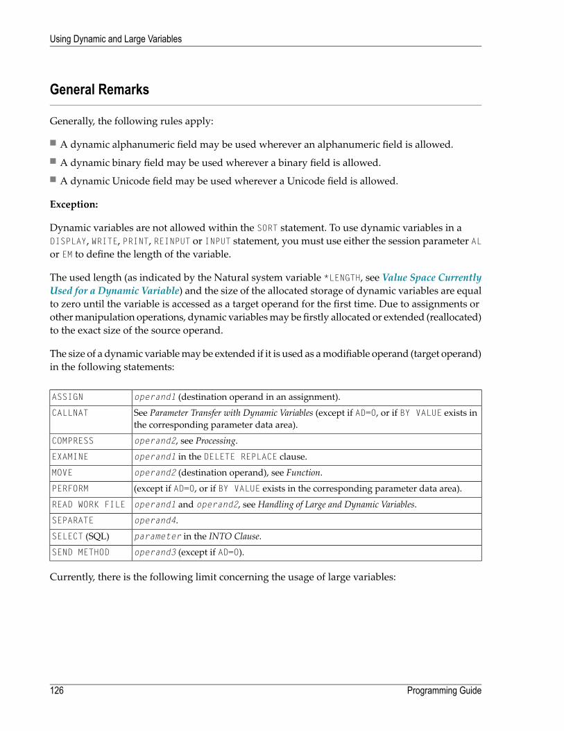
General Remarks
Generally, the following rules apply:
■ A dynamic alphanumeric field may be used wherever an alphanumeric field is allowed.■ A dynamic binary field may be used wherever a binary field is allowed.■ A dynamic Unicode field may be used wherever a Unicode field is allowed.
Exception:
Dynamic variables are not allowed within the SORT statement. To use dynamic variables in aDISPLAY, WRITE, PRINT, REINPUT or INPUT statement, you must use either the session parameter ALor EM to define the length of the variable.
The used length (as indicated by the Natural system variable *LENGTH, see Value Space CurrentlyUsed for a Dynamic Variable) and the size of the allocated storage of dynamic variables are equalto zero until the variable is accessed as a target operand for the first time. Due to assignments orothermanipulation operations, dynamic variablesmay be firstly allocated or extended (reallocated)to the exact size of the source operand.
The size of a dynamic variablemay be extended if it is used as amodifiable operand (target operand)in the following statements:
operand1 (destination operand in an assignment).ASSIGN
See Parameter Transfer with Dynamic Variables (except if AD=O, or if BY VALUE exists inthe corresponding parameter data area).
CALLNAT
operand2, see Processing.COMPRESS
operand1 in the DELETE REPLACE clause.EXAMINE
operand2 (destination operand), see Function.MOVE
(except if AD=O, or if BY VALUE exists in the corresponding parameter data area).PERFORM
operand1 and operand2, see Handling of Large and Dynamic Variables.READ WORK FILE
operand4.SEPARATE
parameter in the INTO Clause.SELECT (SQL)
operand3 (except if AD=O).SEND METHOD
Currently, there is the following limit concerning the usage of large variables:
Programming Guide126
Using Dynamic and Large Variables

Parameter size less than 64 KB per parameter (no limit for CALLwith INTERFACE4 option).CALL
In the following sections, the use of dynamic variables is discussed in more detail on the basis ofexamples.
Assignments with Dynamic Variables
Generally, an assignment is done in the current used length (as indicated by the Natural systemvariable *LENGTH) of the source operand. If the destination operand is a dynamic variable, itscurrent allocated size is possibly extended in order tomove the source operandwithout truncation.
Example:
#MYDYNTEXT1 := OPERANDMOVE OPERAND TO #MYDYNTEXT1/* #MYDYNTEXT1 IS AUTOMATICALLY EXTENDED UNTIL THE SOURCE OPERAND CAN BE COPIED ↩
MOVE ALL, MOVE ALL UNTILwith dynamic target operands are defined as follows:
■ MOVE ALLmoves the source operand repeatedly to the target operand until the used length(*LENGTH) of the target operand is reached. The system variable *LENGTH is not modified. If*LENGTH is zero, the statement will be ignored.
■ MOVE ALL operand1 TO operand2 UNTIL operand3moves operand1 repeatedly to operand2until the length specified in operand3 is reached. If operand3 is greater than *LENGTH(operand2),operand2 is extended and *LENGTH(operand2) is set to operand3. If operand3 is less than*LENGTH(operand2), the used length is reduced to operand3. If operand3 equals*LENGTH(operand2), the behavior is equivalent to MOVE ALL.
Example:
#MYDYNTEXT1 := 'ABCDEFGHIJKLMNO' /* *LENGTH(#MYDYNTEXT1) = 15MOVE ALL 'AB' TO #MYDYNTEXT1 /* CONTENT OF #MYDYNTEXT1 = ↩'ABABABABABABABA'; /* *LENGTH IS STILL 15MOVE ALL 'CD' TO #MYDYNTEXT1 UNTIL 6 /* CONTENT OF #MYDYNTEXT1 = 'CDCDCD'; /* *LENGTH = 6MOVE ALL 'EF' TO #MYDYNTEXT1 UNTIL 10 /* CONTENT OF #MYDYNTEXT1 = 'EFEFEFEFEF'; /* *LENGTH = 10
MOVE JUSTIFIED is rejected at compile time if the target operand is a dynamic variable.
MOVE SUBSTR and MOVE TO SUBSTR are allowed. MOVE SUBSTRwill lead to a runtime error if a sub-string behind the used length of a dynamic variable (*LENGTH) is referenced. MOVE TO SUBSTRwilllead to a runtime error if a sub-string position behind *LENGTH + 1 is referenced, because thiswould lead to an undefined gap in the content of the dynamic variable. If the target operand
127Programming Guide
Using Dynamic and Large Variables

should be extended by MOVE TO SUBSTR (for example if the second operand is set to *LENGTH+1),the third operand is mandatory.
Valid syntax:
#OP2 := *LENGTH(#MYDYNTEXT1)MOVE SUBSTR (#MYDYNTEXT1, #OP2) TO OPERAND /* MOVE LAST CHARACTER ↩TO OPERAND#OP2 := *LENGTH(#MYDYNTEXT1) + 1MOVE OPERAND TO SUBSTR(#MYDYNTEXT1, #OP2, #lEN_OPERAND) /* CONCATENATE OPERAND ↩TO #MYDYNTEXT1 ↩
Invalid syntax:
#OP2 := *LENGTH(#MYDYNTEXT1) + 1MOVE SUBSTR (#MYDYNTEXT1, #OP2, 10) TO OPERAND /* LEADS TO RUNTIME ERROR; ↩UNDEFINED SUB-STRING #OP2 := *LENGTH(#MYDYNTEXT1 + 10) MOVE OPERAND TO SUBSTR(#MYDYNTEXT1, #OP2, #EN_OPERAND) /* LEADS TO RUNTIME ERROR; ↩UNDEFINED GAP#OP2 := *LENGTH(#MYDYNTEXT1) + 1MOVE OPERAND TO SUBSTR(#MYDYNTEXT1, #OP2) /* LEADS TO RUNTIME ERROR; ↩UNDEFINED LENGTH
Assignment Compatibility
Example:
#MYDYNTEXT1 := #MYSTATICVAR1#MYSTATICVAR1 := #MYDYNTEXT2 ↩
If the source operand is a static variable, the used length of the dynamic destination operand(*LENGTH(#MYDYNTEXT1)) is set to the format length of the static variable and the source value iscopied in this length including trailing blanks (alphanumeric and Unicode fields) or binary zeros(for binary fields).
If the destination operand is static and the source operand is dynamic, the dynamic variable iscopied in its currently used length. If this length is less than the format length of the static variable,the remainder is filled with blanks (for alphanumeric and Unicode fields) or binary zeros (forbinary fields). Otherwise, the value will be truncated. If the currently used length of the dynamicvariable is 0, the static target operand is filled with blanks (for alphanumeric and Unicode fields)or binary zeros (for binary fields).
Programming Guide128
Using Dynamic and Large Variables

Initialization of Dynamic Variables
Dynamic variables can be initialized with blanks (alphanumeric and Unicode fields) or zeros(binary fields) up to the currently used length (= *LENGTH) using the RESET statement. The systemvariable *LENGTH is not modified.
Example:
DEFINE DATA LOCAL1 #MYDYNTEXT1 (A) DYNAMICEND-DEFINE#MYDYNTEXT1 := 'SHORT TEXT'WRITE *LENGTH(#MYDYNTEXT1) /* USED LENGTH = 10RESET #MYDYNTEXT1 /* USED LENGTH = 10, VALUE = 10 BLANKS ↩
To initialize a dynamic variable with a specified value in a specified size, the MOVE ALL UNTILstatement may be used.
Example:
MOVE ALL 'Y' TO #MYDYNTEXT1 UNTIL 15 /* #MYDYNTEXT1 CONTAINS 15 'Y'S, USED ↩LENGTH = 15 ↩
String Manipulation with Dynamic Alphanumeric Variables
If a modifiable operand is a dynamic variable, its current allocated size is possibly extended inorder to perform the operation without truncation or an error message. This is valid for the con-catenation (COMPRESS) and separation of dynamic alphanumeric variables (SEPARATE).
Example:
** Example 'DYNAMX01': Dynamic variables (with COMPRESS and SEPARATE)************************************************************************DEFINE DATA LOCAL1 #MYDYNTEXT1 (A) DYNAMIC1 #TEXT (A20)1 #DYN1 (A) DYNAMIC1 #DYN2 (A) DYNAMIC1 #DYN3 (A) DYNAMICEND-DEFINE*MOVE ' HELLO WORLD ' TO #MYDYNTEXT1WRITE #MYDYNTEXT1 (AL=25) 'with length' *LENGTH (#MYDYNTEXT1)/* dynamic variable with leading and trailing blanks*
129Programming Guide
Using Dynamic and Large Variables

MOVE ' HELLO WORLD ' TO #TEXT*MOVE #TEXT TO #MYDYNTEXT1WRITE #MYDYNTEXT1 (AL=25) 'with length' *LENGTH (#MYDYNTEXT1)/* dynamic variable with whole variable length of #TEXT*COMPRESS #TEXT INTO #MYDYNTEXT1WRITE #MYDYNTEXT1 (AL=25) 'with length' *LENGTH (#MYDYNTEXT1)/* dynamic variable with leading blanks of #TEXT**#MYDYNTEXT1 := 'HERE COMES THE SUN'SEPARATE #MYDYNTEXT1 INTO #DYN1 #DYN2 #DYN3 IGNORE*WRITE / #MYDYNTEXT1 (AL=25) 'with length' *LENGTH (#MYDYNTEXT1)WRITE #DYN1 (AL=25) 'with length' *LENGTH (#DYN1)WRITE #DYN2 (AL=25) 'with length' *LENGTH (#DYN2)WRITE #DYN3 (AL=25) 'with length' *LENGTH (#DYN3)/* #DYN1, #DYN2, #DYN3 are automatically extended or reduced*EXAMINE #MYDYNTEXT1 FOR 'SUN' REPLACE 'MOON'WRITE / #MYDYNTEXT1 (AL=25) 'with length' *LENGTH (#MYDYNTEXT1)/* #MYDYNTEXT1 is automatically extended or reduced*END
Note: In case of non-dynamic variables, an error message may be returned.
Logical Condition Criterion (LCC) with Dynamic Variables
Generally, a read-only operation (such as a comparison) with a dynamic variable is done with itscurrently used length. Dynamic variables are processed like static variables if they are used in aread-only (non-modifiable) context.
Example:
IF #MYDYNTEXT1 = #MYDYNTEXT2 OR #MYDYNTEXT1 = "**" THEN ...IF #MYDYNTEXT1 < #MYDYNTEXT2 OR #MYDYNTEXT1 < "**" THEN ...IF #MYDYNTEXT1 > #MYDYNTEXT2 OR #MYDYNTEXT1 > "**" THEN ...
Trailing blanks for alphanumeric andUnicode variables or leading binary zeros for binary variablesare processed in the same way for static and dynamic variables. For example, alphanumeric vari-ables containing the values AA and AA followed by a blank will be considered being equal, andbinary variables containing the values H’0000031’ and H’3031’will be considered being equal.If a comparison result should only be TRUE in case of an exact copy, the used lengths of the dynamicvariables have to be compared in addition. If one variable is an exact copy of the other, their usedlengths are also equal.
Programming Guide130
Using Dynamic and Large Variables
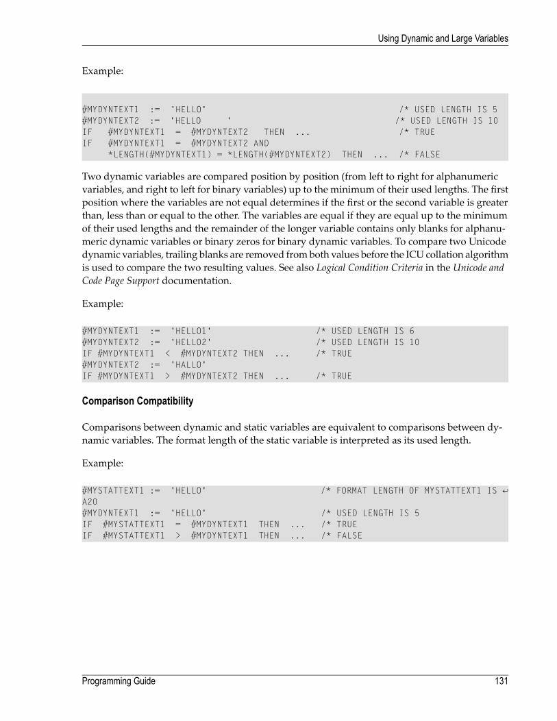
Example:
#MYDYNTEXT1 := 'HELLO' /* USED LENGTH IS 5#MYDYNTEXT2 := 'HELLO ' /* USED LENGTH IS 10IF #MYDYNTEXT1 = #MYDYNTEXT2 THEN ... /* TRUEIF #MYDYNTEXT1 = #MYDYNTEXT2 AND
*LENGTH(#MYDYNTEXT1) = *LENGTH(#MYDYNTEXT2) THEN ... /* FALSE
Two dynamic variables are compared position by position (from left to right for alphanumericvariables, and right to left for binary variables) up to the minimum of their used lengths. The firstposition where the variables are not equal determines if the first or the second variable is greaterthan, less than or equal to the other. The variables are equal if they are equal up to the minimumof their used lengths and the remainder of the longer variable contains only blanks for alphanu-meric dynamic variables or binary zeros for binary dynamic variables. To compare two Unicodedynamic variables, trailing blanks are removed fromboth values before the ICU collation algorithmis used to compare the two resulting values. See also Logical Condition Criteria in the Unicode andCode Page Support documentation.
Example:
#MYDYNTEXT1 := 'HELLO1' /* USED LENGTH IS 6#MYDYNTEXT2 := 'HELLO2' /* USED LENGTH IS 10IF #MYDYNTEXT1 < #MYDYNTEXT2 THEN ... /* TRUE#MYDYNTEXT2 := 'HALLO'IF #MYDYNTEXT1 > #MYDYNTEXT2 THEN ... /* TRUE
Comparison Compatibility
Comparisons between dynamic and static variables are equivalent to comparisons between dy-namic variables. The format length of the static variable is interpreted as its used length.
Example:
#MYSTATTEXT1 := 'HELLO' /* FORMAT LENGTH OF MYSTATTEXT1 IS ↩A20 #MYDYNTEXT1 := 'HELLO' /* USED LENGTH IS 5IF #MYSTATTEXT1 = #MYDYNTEXT1 THEN ... /* TRUEIF #MYSTATTEXT1 > #MYDYNTEXT1 THEN ... /* FALSE
131Programming Guide
Using Dynamic and Large Variables

AT/IF-BREAK of Dynamic Control Fields
The comparison of the break control fieldwith its old value is performed position by position fromleft to right. If the old and the new value of the dynamic variable are of different length, then forcomparison, the value with shorter length is padded to the right (with blanks for alphanumericand Unicode dynamic values or binary zeros for binary values).
In case of an alphanumeric or Unicode break control field, trailing blanks are not significant forthe comparison, that is, trailing blanks do not mean a change of the value and no break occurs.
In case of a binary break control field, trailing binary zeros are not significant for the comparison,that is, trailing binary zeros do not mean a change of the value and no break occurs.
Parameter Transfer with Dynamic Variables
Dynamic variables may be passed as parameters to a called program object (CALLNAT, PERFORM).A call-by-reference is possible because the value space of a dynamic variable is contiguous. A call-by-value causes an assignment with the variable definition of the caller as the source operand andthe parameter definition as the destination operand. A call-by-value result causes in addition themovement in the opposite direction.
For a call-by-reference, both definitionsmust be DYNAMIC. If only one of them is DYNAMIC, a runtimeerror is raised. In the case of a call-by-value (result), all combinations are possible. The followingtable illustrates the valid combinations:
Call By Reference
ParameterCallerDynamicStatic
NoYesStatic
YesNoDynamic
The formats of dynamic variables A or B must match.
Programming Guide132
Using Dynamic and Large Variables

Call by Value (Result)
ParameterCallerDynamicStatic
YesYesStatic
YesYesDynamic
Note: In the case of static/dynamic or dynamic/static definitions, a value truncation mayoccur according to the data transfer rules of the appropriate assignments.
Example 1:
** Example 'DYNAMX02': Dynamic variables (as parameters)************************************************************************DEFINE DATA LOCAL1 #MYTEXT (A) DYNAMICEND-DEFINE*#MYTEXT := '123456' /* extended to 6 bytes, *LENGTH(#MYTEXT) = 6*CALLNAT 'DYNAMX03' USING #MYTEXT * WRITE *LENGTH(#MYTEXT) /* *LENGTH(#MYTEXT) = 8 * END ↩
Subprogram DYNAMX03:
** Example 'DYNAMX03': Dynamic variables (as parameters) ************************************************************************DEFINE DATA PARAMETER 1 #MYPARM (A) DYNAMIC BY VALUE RESULT END-DEFINE * WRITE *LENGTH(#MYPARM) /* *LENGTH(#MYPARM) = 6 #MYPARM := '1234567' /* *LENGTH(#MYPARM) = 7 #MYPARM := '12345678' /* *LENGTH(#MYPARM) = 8 EXPAND DYNAMIC VARIABLE #MYPARM TO 10 /* 10 bytes are allocated * WRITE *LENGTH(#MYPARM) /* *LENGTH(#MYPARM) = 8 * /* content of #MYPARM is moved back to #MYTEXT /* used length of #MYTEXT = 8 * END ↩
133Programming Guide
Using Dynamic and Large Variables

Example 2:
** Example 'DYNAMX04': Dynamic variables (as parameters)************************************************************************DEFINE DATA LOCAL1 #MYTEXT (A) DYNAMICEND-DEFINE*#MYTEXT := '123456' /* extended to 6 bytes, *LENGTH(#MYTEXT) = 6*CALLNAT 'DYNAMX05' USING #MYTEXT * WRITE *LENGTH(#MYTEXT) /* *LENGTH(#MYTEXT) = 8 /* at least 10 bytes are /* allocated (extended in DYNAMX05) * END ↩
Subprogram DYNAMX05:
** Example 'DYNAMX05': Dynamic variables (as parameters) ************************************************************************DEFINE DATA PARAMETER 1 #MYPARM (A) DYNAMIC END-DEFINE * WRITE *LENGTH(#MYPARM) /* *LENGTH(#MYPARM) = 6 #MYPARM := '1234567' /* *LENGTH(#MYPARM) = 7 #MYPARM := '12345678' /* *LENGTH(#MYPARM) = 8 EXPAND DYNAMIC VARIABLE #MYPARM TO 10 /* 10 bytes are allocated * WRITE *LENGTH(#MYPARM) /* *LENGTH(#MYPARM) = 8 * END ↩
CALL 3GL Program
Dynamic and large variables can sensibly be used with the CALL statement when the optionINTERFACE4 is used. Using this option leads to an interface to the 3GL program with a differentparameter structure.
This usage requires someminor changes in the 3GLprogram, but provides the following significantbenefits as compared with the older FINFO structure.
■ No limitation on the number of passed parameters (former limit 40).■ No limitation on the parameter's data size (former limit 64 KB per parameter).
Programming Guide134
Using Dynamic and Large Variables
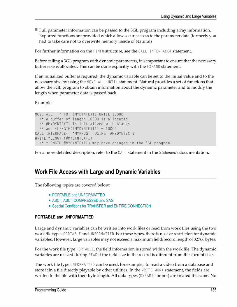
■ Full parameter information can be passed to the 3GL program including array information.Exported functions are providedwhich allow secure access to the parameter data (formerly youhad to take care not to overwrite memory inside of Natural)
For further information on the FINFO structure, see the CALL INTERFACE4 statement.
Before calling a 3GLprogramwith dynamic parameters, it is important to ensure that the necessarybuffer size is allocated. This can be done explicitly with the EXPAND statement.
If an initialized buffer is required, the dynamic variable can be set to the initial value and to thenecessary size by using the MOVE ALL UNTIL statement. Natural provides a set of functions thatallow the 3GL program to obtain information about the dynamic parameter and to modify thelength when parameter data is passed back.
Example:
MOVE ALL ' ' TO #MYDYNTEXT1 UNTIL 10000/* a buffer of length 10000 is allocated/* #MYDYNTEXT1 is initialized with blanks/* and *LENGTH(#MYDYNTEXT1) = 10000
CALL INTERFACE4 'MYPROG' USING #MYDYNTEXT1WRITE *LENGTH(#MYDYNTEXT1)
/* *LENGTH(#MYDYNTEXT1) may have changed in the 3GL program
For a more detailed description, refer to the CALL statement in the Statements documentation.
Work File Access with Large and Dynamic Variables
The following topics are covered below:
■ PORTABLE and UNFORMATTED■ ASCII, ASCII-COMPRESSED and SAG■ Special Conditions for TRANSFER and ENTIRE CONNECTION
PORTABLE and UNFORMATTED
Large and dynamic variables can be written into work files or read from work files using the twowork file types PORTABLE and UNFORMATTED. For these types, there is no size restriction for dynamicvariables. However, large variablesmay not exceed amaximumfield/record length of 32766 bytes.
For the work file type PORTABLE, the field information is stored within the work file. The dynamicvariables are resized during READ if the field size in the record is different from the current size.
The work file type UNFORMATTED can be used, for example, to read a video from a database andstore it in a file directly playable by other utilities. In the WRITE WORK statement, the fields arewritten to the file with their byte length. All data types (DYNAMIC or not) are treated the same. No
135Programming Guide
Using Dynamic and Large Variables

structural information is inserted.Note thatNatural uses a bufferingmechanism, so you can expectthe data to be completely written only after a CLOSE WORK. This is especially important if the fileis to be processed with another utility while Natural is running.
With the READ WORK statement, fields of fixed length are read with their whole length. If the end-of-file is reached, the remainder of the current field is filled with blanks. The following fields areunchanged. In the case of DYNAMIC data types, all the remainder of the file is read unless it exceeds1073741824 bytes. If the end of file is reached, the remaining fields (variables) are kept unchanged(normal Natural behavior).
ASCII, ASCII-COMPRESSED and SAG
Theworkfile typesASCII,ASCII-COMPRESSEDandSAG (binary) cannot handledynamic variablesand will produce an error. Large variables for these work file types pose no problem unless themaximum field/record length of 32766 bytes is exceeded.
Special Conditions for TRANSFER and ENTIRE CONNECTION
In conjunctionwith the READ WORK FILE statement, thework file type TRANSFER can handle dynamicvariables. There is no size limit for dynamic variables. The work file type ENTIRE CONNECTIONcannot handle dynamic variables. They can both, however, handle large variableswith amaximumfield/record length of 1073741824 bytes.
In conjunction with the WRITE WORK FILE statement, the work file type TRANSFER can handle dy-namic variables with a maximum field/record length of 32766 bytes. The work file type ENTIRECONNECTION cannot handle dynamic variables. They can both, however, handle large variableswith a maximum field/record length of 1073741824 bytes.
DDM Generation and Editing for Varying Length Columns
Depending on the data types, the related database format A or format B is generated. For thedatabases' data type VARCHAR the Natural length of the column is set to the maximum length ofthe data type as defined in theDBMS. If a data type is very large, the keyword DYNAMIC is generatedat the length field position.
For all varying length columns, an LINDICATOR field L@<column-name>will be generated. For thedatabases' data type VARCHAR, an LINDICATOR field with format/length I2 will be generated. Forlarge data types (see list below) the format/length will be I4.
In the context of database access, the LINDICATOR handling offers the chance to get the length ofthe field to be read or to set the length of the field to be written independent of a defined bufferlength (or independent of *LENGTH). Usually, after a retrieval function, *LENGTHwill be set to thecorresponding length indicator value.
Programming Guide136
Using Dynamic and Large Variables

Example DDM:
T L Name F Leng S D Remark : 1 L@PICTURE1 I 4 /* ↩length indicator 1 PICTURE1 B DYNAMIC IMAGE 1 N@PICTURE1 I 2 /* NULL ↩indicator 1 L@TEXT1 I 4 /* ↩length indicator 1 TEXT1 A DYNAMIC TEXT 1 N@TEXT1 I 2 /* NULL ↩indicator 1 L@DESCRIPTION I 2 /* ↩length indicator 1 DESCRIPTION A 1000 VARCHAR(1000) : : ~~~~~~~~~~~~~~~~~~~~~~Extended Attributes~~~~~~~~~~~~~~~~~~~~~~~~~~~~~~~~~/* ↩concerning PICTURE1 Header : --- Edit Mask : --- Remarks : IMAGE
The generated formats are varying length formats. The Natural programmer has the chance tochange the definition from DYNAMIC to a fixed length definition (extended field editing) and canchange, for example, the corresponding DDMfield definition for VARCHAR data types to amultiplevalue field (old generation).
Example:
T L Name F Leng S D Remark : 1 L@PICTURE1 I 4 /* ↩length indicator 1 PICTURE1 B 1000000000 IMAGE 1 N@PICTURE1 I 2 /* NULL ↩indicator 1 L@TEXT1 I 4 /* ↩length indicator 1 TEXT1 A 5000 TEXT 1 N@TEXT1 I 2 /* NULL ↩indicator 1 L@DESCRIPTION I 2 /* ↩length indicator M 1 DESCRIPTION A 100 VARCHAR(1000) : : ~~~~~~~~~~~~~~~~~~~~Extended Attributes~~~~~~~~~~~~~~~~~~~~~~~~~~~~~~~~~~~/* ↩concerning PICTURE1
137Programming Guide
Using Dynamic and Large Variables

Header : --- Edit Mask : --- Remarks : IMAGE
Accessing Large Database Objects
To access a database with large objects (CLOBs or BLOBs), a DDMwith corresponding large al-phanumeric, Unicode or binary fields is required. If a fixed length is defined and if the databaselarge object does not fit into this field, the large object is truncated. If the programmer does notknow the definitive length of the database object, it will make sense to work with dynamic fields.As many reallocations as necessary are done to hold the object. No truncation is performed.
Example Program:
DEFINE DATA LOCAL
1 person VIEW OF xyz-person 2 last_name 2 first_name_1 2 L@PICTURE1 /* I4 length indicator for PICTURE1 2 PICTURE1 /* defined as dynamic in the DDM 2 TEXT1 /* defined as non-dynamic in the DDM
END-DEFINE
SELECT * INTO VIEW person FROM xyz-person /* PICTURE1 will be ↩read completely WHERE last_name = 'SMITH' /* TEXT1 will be ↩truncated to fixed length 5000
WRITE 'length of PICTURE1: ' L@PICTURE1 /* the L-INDICATOR will ↩contain the length /* of PICTURE1 (= ↩*LENGTH(PICTURE1) /* do something with PICTURE1 and TEXT1
L@PICTURE1 := 100000 INSERT INTO xyz-person (*) VALUES (VIEW person) /* only the first 100000 ↩Bytes of PICTURE1 /* are insertedEND-SELECT ↩
If a format-length definition is omitted in the view, this is taken from theDDM. In reportingmode,it is now possible to specify any length, if the corresponding DDMfield is defined as DYNAMIC. Thedynamic field will be mapped to a field with a fixed buffer length. The other way round is notpossible.
Programming Guide138
Using Dynamic and Large Variables

VIEW format / length definitionDDM format/length definition
valid-(An)
valid(An)
only valid in reporting mode(Am)
invalid(A) DYNAMIC
valid-(A) DYNAMIC
valid(A) DYNAMIC
only valid in reporting mode(An)
only valid in reporting mode(Am / i : j)
(equivalent for Format B variables)
Parameter with LINDICATOR Clause in SQL Statements
If the LINDICATOR field is defined as an I2 field, the SQL data type VARCHAR is used for sending orreceiving the corresponding column. If the LINDICATOR host variable is specified as I4, a large objectdata type (CLOB/BLOB) is used.
If the field is defined as DYNAMIC, the column is read in an internal loop up to its real length. TheLINDICATOR field and the system variable *LENGTH are set to this length. In the case of a fixed-lengthfield, the column is read up to the defined length. In both cases, the field is written up to the valuedefined in the LINDICATOR field.
Performance Aspects with Dynamic Variables
If a dynamic variable is to be expanded in small quantitiesmultiple times (for example, byte-wise),use the EXPAND statement before the iterations if the upper limit of required storage is (approxim-ately) known. This avoids additional overhead to adjust the storage needed.
Use the REDUCE or RESIZE statement if the dynamic variable will no longer be needed, especiallyfor variables with a high value of the system variable *LENGTH. This enables Natural you to releaseor reuse the storage. Thus, the overall performance may be improved.
The amount of the allocated memory of a dynamic variable may be reduced using the REDUCEDYNAMIC VARIABLE statement. In order to (re)allocate a variable to a specified length, the EXPANDstatement can be used. (If the variable should be initialized, use the MOVE ALL UNTIL statement.)
139Programming Guide
Using Dynamic and Large Variables

Example:
** Example 'DYNAMX06': Dynamic variables (allocated memory)************************************************************************DEFINE DATA LOCAL1 #MYDYNTEXT1 (A) DYNAMIC1 #LEN (I4)END-DEFINE*#MYDYNTEXT1 := 'a' /* used length is 1, value is 'a'
/* allocated size is still 1WRITE *LENGTH(#MYDYNTEXT1)*EXPAND DYNAMIC VARIABLE #MYDYNTEXT1 TO 100
/* used length is still 1, value is 'a'/* allocated size is 100
*CALLNAT 'DYNAMX05' USING #MYDYNTEXT1WRITE *LENGTH(#MYDYNTEXT1)
/* used length and allocated size/* may have changed in the subprogram
*#LEN := *LENGTH(#MYDYNTEXT1)REDUCE DYNAMIC VARIABLE #MYDYNTEXT1 TO #LEN
/* if allocated size is greater than used length,/* the unused memory is released
*REDUCE DYNAMIC VARIABLE #MYDYNTEXT1 TO 0WRITE *LENGTH(#MYDYNTEXT1)
/* free allocated memory for dynamic variableEND
Rules:
■ Use dynamic operands where it makes sense.■ Use the EXPAND statement if upper limit of memory usage is known.■ Use the REDUCE statement if the dynamic operand will no longer be needed.
Outputting Dynamic Variables
Dynamic variables may be used inside output statements such as the following:
Programming Guide140
Using Dynamic and Large Variables
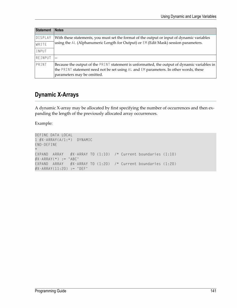
NotesStatement
With these statements, you must set the format of the output or input of dynamic variablesusing the AL (Alphanumeric Length for Output) or EM (Edit Mask) session parameters.
DISPLAY
WRITE
INPUT
--REINPUT
Because the output of the PRINT statement is unformatted, the output of dynamic variables inthe PRINT statement need not be set using AL and EM parameters. In other words, theseparameters may be omitted.
Dynamic X-Arrays
A dynamic X-array may be allocated by first specifying the number of occurrences and then ex-panding the length of the previously allocated array occurrences.
Example:
DEFINE DATA LOCAL1 #X-ARRAY(A/1:*) DYNAMICEND-DEFINE*EXPAND ARRAY #X-ARRAY TO (1:10) /* Current boundaries (1:10)#X-ARRAY(*) := 'ABC'EXPAND ARRAY #X-ARRAY TO (1:20) /* Current boundaries (1:20)#X-ARRAY(11:20) := 'DEF'
141Programming Guide
Using Dynamic and Large Variables

142

18 User-Defined Constants
■ Numeric Constants ........................................................................................................................ 144■ Alphanumeric Constants ................................................................................................................. 145■ Unicode Constants ......................................................................................................................... 146■ Date and Time Constants ................................................................................................................ 149■ Hexadecimal Constants .................................................................................................................. 150■ Logical Constants .......................................................................................................................... 152■ Floating Point Constants ................................................................................................................. 152■ Attribute Constants ........................................................................................................................ 153■ Handle Constants .......................................................................................................................... 154■ Defining Named Constants .............................................................................................................. 154
143

Constants can be used throughout Natural programs. This document discusses the types of con-stants that are supported and how they are used.
Numeric Constants
The following topics are covered below:
■ Numeric Constants■ Validation of Numeric Constants
Numeric Constants
A numeric constant may contain 1 to 29 numeric digits, a special character as decimal separator(period or comma) and a sign.
Examples:
1234 +1234 -1234
12.34 +12.34 -12.34
MOVE 3 TO #XYZCOMPUTE #PRICE = 23.34COMPUTE #XYZ = -103COMPUTE #A = #B * 6074
Note: Internally, numeric constants without decimal digits are represented in integer form(format I), while numeric constantswith decimal digits, aswell as numeric constantswithoutdecimal digits that are too large to fit into format I, are represented in packed form (formatP).
Example:
LengthFormatNumeric ConstantToFrom
>=10P<= -2147483649
4I-32769-2147483648
2I32767-32768
4I214748364732768
>=10P>= 2147483648
Programming Guide144
User-Defined Constants
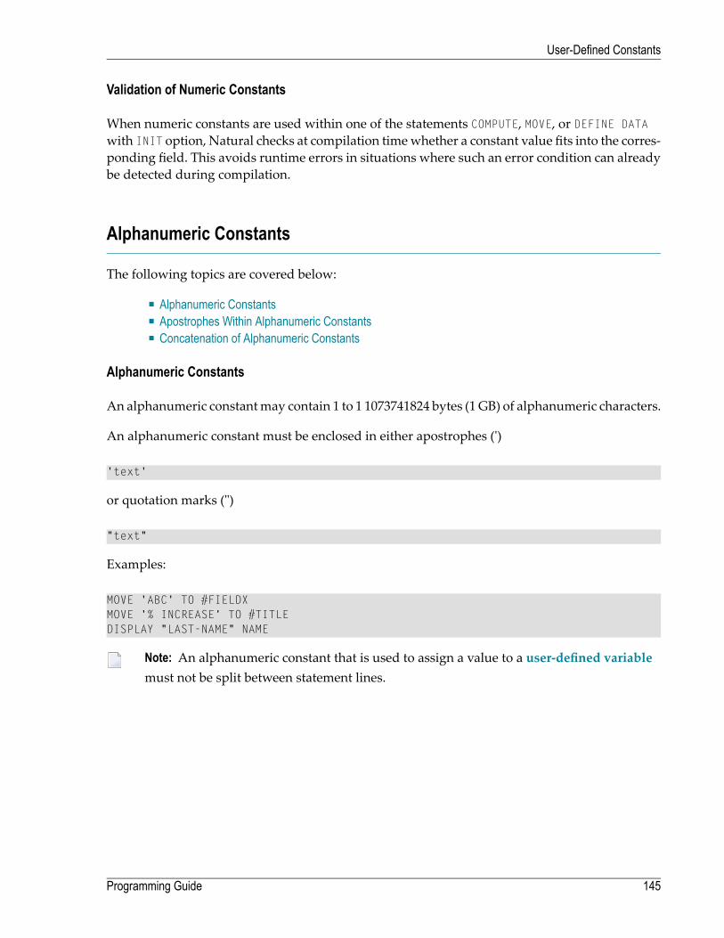
Validation of Numeric Constants
When numeric constants are used within one of the statements COMPUTE, MOVE, or DEFINE DATAwith INIT option, Natural checks at compilation timewhether a constant value fits into the corres-ponding field. This avoids runtime errors in situations where such an error condition can alreadybe detected during compilation.
Alphanumeric Constants
The following topics are covered below:
■ Alphanumeric Constants■ Apostrophes Within Alphanumeric Constants■ Concatenation of Alphanumeric Constants
Alphanumeric Constants
An alphanumeric constantmay contain 1 to 1 1073741824 bytes (1 GB) of alphanumeric characters.
An alphanumeric constant must be enclosed in either apostrophes (')
'text'
or quotation marks (")
"text"
Examples:
MOVE 'ABC' TO #FIELDXMOVE '% INCREASE' TO #TITLEDISPLAY "LAST-NAME" NAME
Note: An alphanumeric constant that is used to assign a value to a user-defined variablemust not be split between statement lines.
145Programming Guide
User-Defined Constants

Apostrophes Within Alphanumeric Constants
If you want an apostrophe to be part of an alphanumeric constant that is enclosed in apostrophes,you must write this as two apostrophes or as a single quotation mark.
If you want an apostrophe to be part of an alphanumeric constant that is enclosed in quotationmarks, you write this as a single apostrophe.
Example:
If you want the following to be output:
HE SAID, 'HELLO'
you can use any of the following notations:
WRITE 'HE SAID, ''HELLO'''WRITE 'HE SAID, "HELLO"'WRITE "HE SAID, ""HELLO"""WRITE "HE SAID, 'HELLO'"
Note: If quotation marks are not converted to apostrophes as shown above, this is due tothe setting of profile parameter TQMARK (Translate Quotation Marks); ask your Natural ad-ministrator for details.
Concatenation of Alphanumeric Constants
Alphanumeric constants may be concatenated to form a single value by use of a hyphen.
Examples:
MOVE 'XXXXXX' - 'YYYYYY' TO #FIELDMOVE "ABC" - 'DEF' TO #FIELD
In this way, alphanumeric constants can also be concatenated with hexadecimal constants.
Unicode Constants
The following topics are covered below:
■ Unicode Text Constants■ Apostrophes Within Unicode Text Constants■ Unicode Hexadecimal Constants
Programming Guide146
User-Defined Constants

■ Concatenation of Unicode Constants
Unicode Text Constants
A Unicode text constant must be preceded by the character U and enclosed in either apostrophes(')
U'text'
or quotation marks (")
U"text"
Example:
U'HELLO'
The compiler stores this text constant in the generated program in Unicode format (UTF-16).
Apostrophes Within Unicode Text Constants
If you want an apostrophe to be part of a Unicode text constant that is enclosed in apostrophes,you must write this as two apostrophes or as a single quotation mark.
If youwant an apostrophe to be part of aUnicode text constant that is enclosed in quotationmarks,you write this as a single apostrophe.
Example:
If you want the following to be output:
HE SAID, 'HELLO'
you can use any of the following notations:
WRITE U'HE SAID, ''HELLO'''WRITE U'HE SAID, "HELLO"'WRITE U"HE SAID, ""HELLO"""WRITE U"HE SAID, 'HELLO'"
Note: If quotation marks are not converted to apostrophes as shown above, this is due tothe setting of the profile parameter TQ (Translate Quotation Marks); ask your Natural ad-ministrator for details.
147Programming Guide
User-Defined Constants

Unicode Hexadecimal Constants
The following syntax is used to supply a Unicode character or a Unicode string by its hexadecimalnotation:
UH'hhhh...'
where h represents a hexadecimal digit (0-9, A-F). Since a UTF-16 Unicode character consists of adouble-byte, the number of hexadecimal characters supplied has to be a multiple of four.
Example:
This example defines the string 45.
UH'00340035'
Concatenation of Unicode Constants
Concatenation of Unicode text constants (U) andUnicode hexadecimal constants (UH) is allowed.
Valid Example:
MOVE U'XXXXXX' - UH'00340035' TO #FIELD
Unicode text constants or Unicode hexadecimal constants cannot be concatenated with code pagealphanumeric constants or H constants.
Invalid Example:
MOVE U'ABC' - 'DEF' TO #FIELDMOVE UH'00340035' - H'414243' TO #FIELD
Further Valid Example:
DEFINE DATA LOCAL1 #U10 (U10) /* Unicode variable with 10 (UTF-16) characters, total ↩byte length = 201 #UD (U) DYNAMIC /* Unicode variable with dynamic lengthEND-DEFINE*#U10 := U'ABC' /* Constant is created as X'004100420043' in the object, ↩the UTF-16 representation for string 'ABC'.
#U10 := UH'004100420043' /* Constant supplied in hexadecimal format only, ↩corresponds to U'ABC'
#U10 := U'A'-UH'0042'-U'C' /* Constant supplied in mixed formats, corresponds to ↩U'ABC'.END
Programming Guide148
User-Defined Constants

Date and Time Constants
The following topics are covered below:
■ Date Constant■ Time Constant■ Extended Time Constant
Date Constant
A date constant may be used in conjunction with a format D variable.
Date constants may have the following formats:
International date formatD'yyyy-mm-dd'
German date formatD'dd.mm.yyyy'
European date formatD'dd/mm/yyyy'
US date formatD'mm/dd/yyyy'
where dd represents the number of the day, mm the number of the month and yyyy the year.
Example:
DEFINE DATA LOCAL1 #DATE (D)END-DEFINE...MOVE D'2004-03-08' TO #DATE...
The default date format is controlled by the profile parameter DTFORM (Date Format) as set by theNatural administrator.
Time Constant
A time constant may be used in conjunction with a format T variable.
A time constant has the following format:
149Programming Guide
User-Defined Constants

T'hh:ii:ss'
where hh represents hours, iiminutes and ss seconds.
Example:
DEFINE DATA LOCAL1 #TIME (T)END-DEFINE...MOVE T'11:33:00' TO #TIME...
Extended Time Constant
A time variable (format T) can contain date and time information, date information being a subsetof time information; however, with a “normal” time constant (prefix T) only the time informationof a time variable can be handled:
T'hh:ii:ss'
With an extended time constant (prefix E), it is possible to handle the full content of a time variable,including the date information:
E'yyyy-mm-dd hh:ii:ss'
Apart from that, the use of an extended time constant in conjunction with a time variable is thesame as for a normal time constant.
Note: The format in which the date information has to be specified in an extended timeconstant depends on the setting of the profile parameter DTFORM. The extended time constantshown above assumes DTFORM=I (international date format).
Hexadecimal Constants
The following topics are covered below:
■ Hexadecimal Constants
Programming Guide150
User-Defined Constants

■ Concatenation of Hexadecimal Constants
Hexadecimal Constants
A hexadecimal constant may be used to enter a value which cannot be entered as a standard key-board character.
A hexadecimal constant may contain 1 to 1073741824 bytes (1 GB) of alphanumeric characters.
A hexadecimal constant is prefixed with an H. The constant itself must be enclosed in apostrophesandmay consist of the hexadecimal characters 0 - 9, A - F. Two hexadecimal characters are requiredto represent one byte of data.
The hexadecimal representation of a character varies, depending on whether your computer usesanASCII or EBCDIC character set.When you transfer hexadecimal constants to another computer,you may therefore have to convert the characters.
ASCII examples:
H'313233' (equivalent to the alphanumeric constant '123')H'414243' (equivalent to the alphanumeric constant 'ABC')
EBCDIC examples:
H'F1F2F3' (equivalent to the alphanumeric constant '123')H'C1C2C3' (equivalent to the alphanumeric constant 'ABC')
When a hexadecimal constant is transferred to another field, it will be treated as an alphanumericvalue (format A).
The data transfer of an alphanumeric value (format A) to a field which is defined with a formatother than A,U or B is not allowed. Therefore, a hexadecimal constant used as initial value in aDEFINE DATA statement is rejected with the syntax error NAT0094 if the corresponding variableis not of format A, U or B.
Example:
DEFINE DATA LOCAL1 #I(I2) INIT <H'000F'> /* causes a NAT0094 syntax error END-DEFINE ↩
151Programming Guide
User-Defined Constants
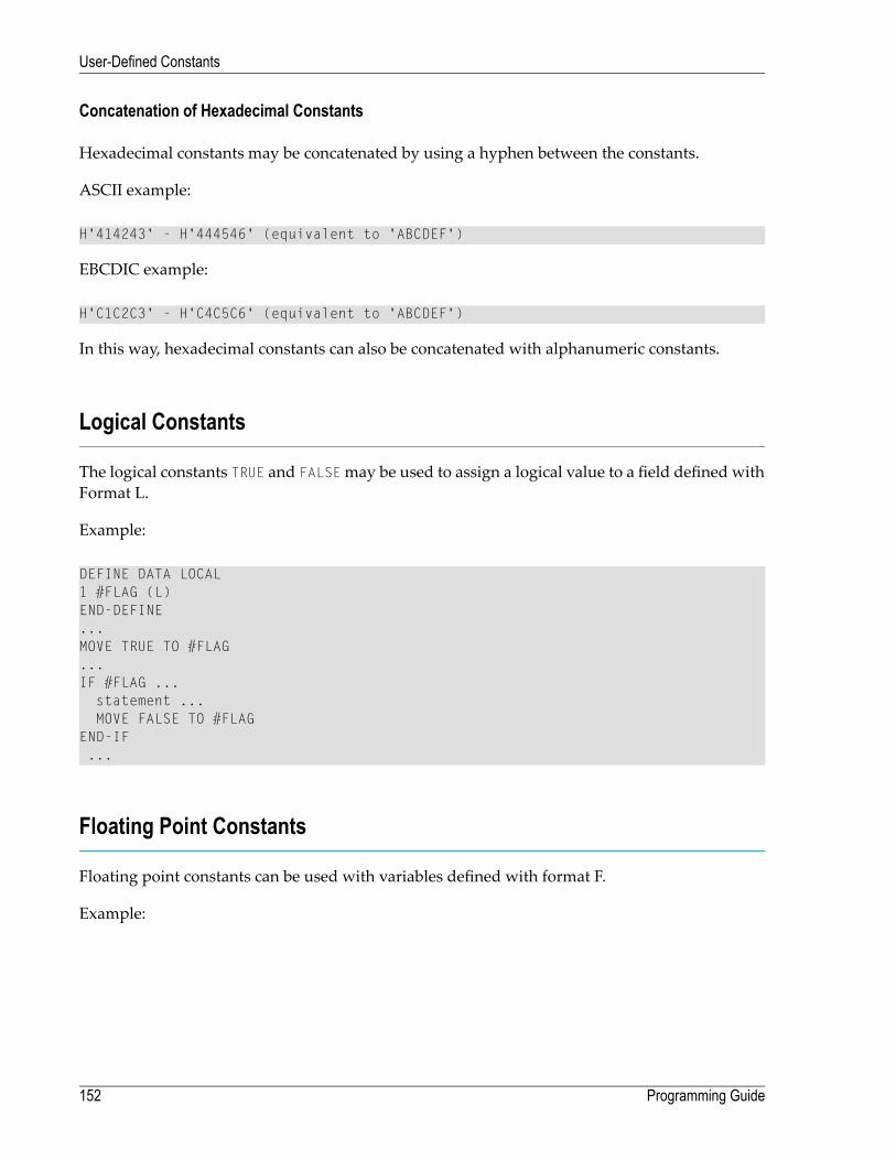
Concatenation of Hexadecimal Constants
Hexadecimal constants may be concatenated by using a hyphen between the constants.
ASCII example:
H'414243' - H'444546' (equivalent to 'ABCDEF')
EBCDIC example:
H'C1C2C3' - H'C4C5C6' (equivalent to 'ABCDEF')
In this way, hexadecimal constants can also be concatenated with alphanumeric constants.
Logical Constants
The logical constants TRUE and FALSEmay be used to assign a logical value to a field defined withFormat L.
Example:
DEFINE DATA LOCAL1 #FLAG (L)END-DEFINE...MOVE TRUE TO #FLAG...IF #FLAG ...
statement ...MOVE FALSE TO #FLAG
END-IF...
Floating Point Constants
Floating point constants can be used with variables defined with format F.
Example:
Programming Guide152
User-Defined Constants

DEFINE DATA LOCAL1 #FLT1 (F4)END-DEFINE...COMPUTE #FLT1 = -5.34E+2...
Attribute Constants
Attribute constants can be usedwith variables definedwith format C (control variables). This typeof constant must be enclosed within parentheses.
The following attributes may be used:
DescriptionAttribute
defaultAD=D
blinkingAD=B
intensifiedAD=I
non-displayAD=N
reverse videoAD=V
underlinedAD=U
cursive/italicAD=C
dynamic attributeAD=Y
protectedAD=P
blueCD=BL
greenCD=GR
neutralCD=NE
pinkCD=PI
redCD=RE
turquoiseCD=TU
yellowCD=YE
See also session parameters AD and CD.
Example:
153Programming Guide
User-Defined Constants
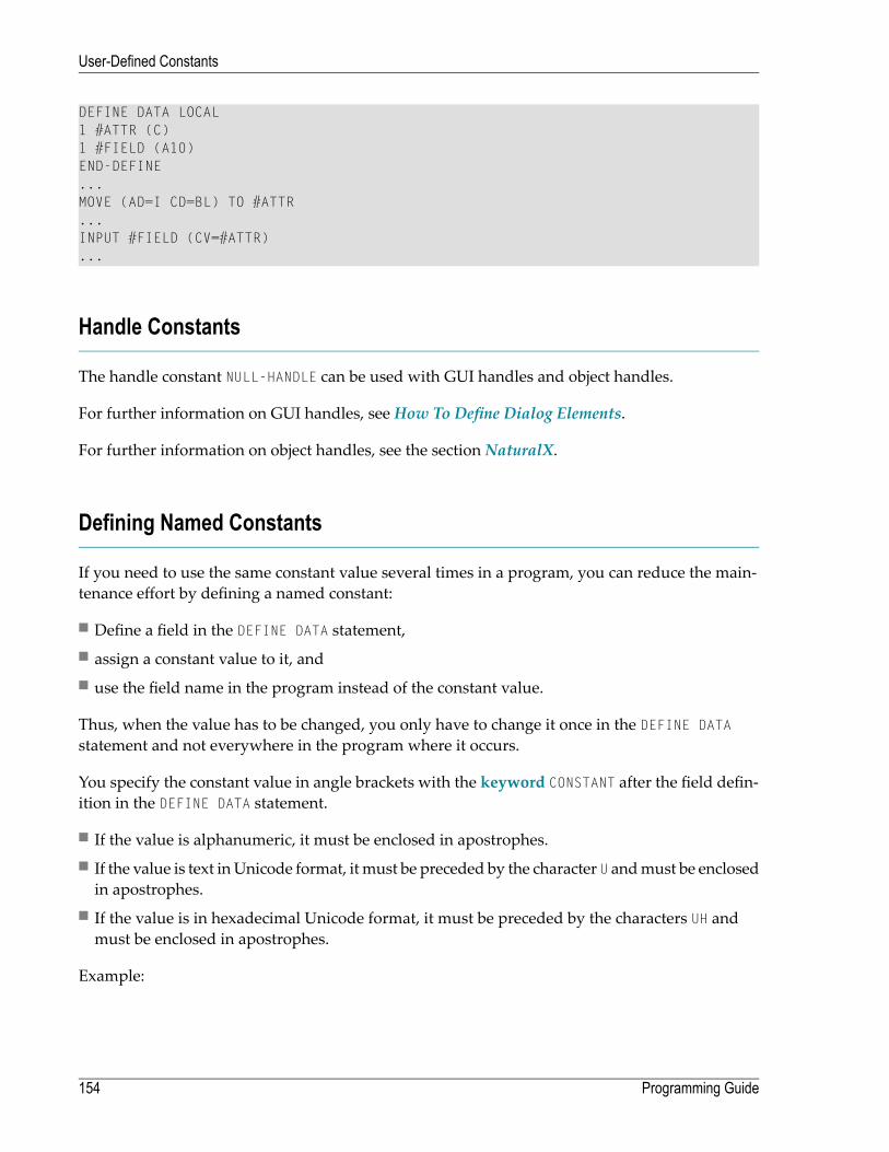
DEFINE DATA LOCAL1 #ATTR (C)1 #FIELD (A10)END-DEFINE...MOVE (AD=I CD=BL) TO #ATTR...INPUT #FIELD (CV=#ATTR)...
Handle Constants
The handle constant NULL-HANDLE can be used with GUI handles and object handles.
For further information on GUI handles, see How To Define Dialog Elements.
For further information on object handles, see the section NaturalX.
Defining Named Constants
If you need to use the same constant value several times in a program, you can reduce the main-tenance effort by defining a named constant:
■ Define a field in the DEFINE DATA statement,■ assign a constant value to it, and■ use the field name in the program instead of the constant value.
Thus, when the value has to be changed, you only have to change it once in the DEFINE DATAstatement and not everywhere in the program where it occurs.
You specify the constant value in angle brackets with the keyword CONSTANT after the field defin-ition in the DEFINE DATA statement.
■ If the value is alphanumeric, it must be enclosed in apostrophes.■ If the value is text inUnicode format, it must be preceded by the character U andmust be enclosedin apostrophes.
■ If the value is in hexadecimal Unicode format, it must be preceded by the characters UH andmust be enclosed in apostrophes.
Example:
Programming Guide154
User-Defined Constants

DEFINE DATA LOCAL1 #FIELDA (N3) CONSTANT <100>1 #FIELDB (A5) CONSTANT <'ABCDE'>1 #FIELDC (U5) CONSTANT <U'ABCDE'>1 #FIELDD (U5) CONSTANT <UH'00410042004300440045'>END-DEFINE...
During the execution of the program, the value of such a named constant cannot be modified.
155Programming Guide
User-Defined Constants

156

19 Initial Values (and the RESET Statement)
■ Default Initial Value of a User-Defined Variable/Array ............................................................................ 158■ Assigning an Initial Value to a User-Defined Variable/Array ..................................................................... 158■ Resetting a User-Defined Variable to its Initial Value ............................................................................. 160
157

This chapter describes the default initial values of user-defined variables, explains how you canassign an initial value to a user-defined variable and how you can use the RESET statement to resetthe field value to its default initial value or the initial value defined for that variable in the DEFINEDATA statement.
Default Initial Value of a User-Defined Variable/Array
If you specify no initial value for a field, the field will be initialized with a default initial valuedepending on its format:
Default Initial ValueFormat
0B, F, I, N, P
blankA, U
F(ALSE)L
D' 'D
T'00:00:00'T
(AD=D)C
NULL-HANDLEGUI Handle
NULL-HANDLEObject Handle
Assigning an Initial Value to a User-Defined Variable/Array
In the DEFINE DATA statement, you can assign an initial value to a user-defined variable. If theinitial value is alphanumeric, it must be enclosed in apostrophes.
■ Assigning a Modifiable Initial Value■ Assigning a Constant Initial Value■ Assigning a Natural System Variable as Initial Value
Programming Guide158
Initial Values (and the RESET Statement)

■ Assigning Characters as Initial Value for Alphanumeric Variables
Assigning a Modifiable Initial Value
If the variable/array is to be assigned a modifiable initial value, you specify the initial value inangle brackets with the keyword INIT after the variable definition in the DEFINE DATA statement.The value(s) assignedwill be used each time the variable/array is referenced. The value(s) assignedcan be modified during program execution.
Example:
DEFINE DATA LOCAL1 #FIELDA (N3) INIT <100>1 #FIELDB (A20) INIT <'ABC'>END-DEFINE...
Assigning a Constant Initial Value
If the variable/array is to be treated as a named constant, you specify the initial value in anglebrackets with the keyword CONSTANT after the variable definition in the DEFINE DATA statement.The constant value(s) assignedwill be used each time the variable/array is referenced. The value(s)assigned cannot be modified during program execution.
Example:
DEFINE DATA LOCAL1 #FIELDA (N3) CONST <100>1 #FIELDB (A20) CONST <'ABC'>END-DEFINE...
Assigning a Natural System Variable as Initial Value
The initial value for a field may also be the value of a Natural system variable.
Example:
In this example, the system variable *DATX is used to provide the initial value.
159Programming Guide
Initial Values (and the RESET Statement)

DEFINE DATA LOCAL1 #MYDATE (D) INIT <*DATX>END-DEFINE...
Assigning Characters as Initial Value for Alphanumeric Variables
As initial value, a variable can also be filled, entirely or partially, with a specific single characteror string of characters (only possible for alphanumeric variables).
■ Filling an entire field:With the option FULL LENGTH <character(s)>, the entire field is filled with the specified char-acter(s).
In this example, the entire field will be filled with asterisks.
DEFINE DATA LOCAL1 #FIELD (A25) INIT FULL LENGTH <'*'>END-DEFINE...
■ Filling the firstn positions of a field:With the option LENGTH n <character(s)>, the first n positions of the field are filled with thespecified character(s).
In this example, the first 4 positions of the field will be filled with exclamation marks.
DEFINE DATA LOCAL1 #FIELD (A25) INIT LENGTH 4 <'!'>END-DEFINE...
Resetting a User-Defined Variable to its Initial Value
The RESET statement is used to reset the value of a field. Two options are available:
■ Reset to Default Initial Value■ Reset to Initial Value Defined in DEFINE DATA
Notes:
1. A field declared with a CONSTANT clause in the DEFINE DATA statement may not be referencedin a RESET statement, since its content cannot be changed.
Programming Guide160
Initial Values (and the RESET Statement)

2. In reporting mode, the RESET statement may also be used to define a variable, provided thatthe program contains no DEFINE DATA LOCAL statement.
Reset to Default Initial Value
RESET (without INITIAL) sets the content of each specifiedfield to itsdefault initial valuedependingon its format.
Example:
DEFINE DATA LOCAL 1 #FIELDA (N3) INIT <100> 1 #FIELDB (A20) INIT <'ABC'> 1 #FIELDC (I4) INIT <5> END-DEFINE ... ... RESET #FIELDA /* resets field value to default initial value ... ↩
Reset to Initial Value Defined in DEFINE DATA
RESET INITIAL sets each specified field to the initial value as defined for the field in the DEFINEDATA statement.
For a field declared without INIT clause in the DEFINE DATA statement, RESET INITIAL has thesame effect as RESET (without INITIAL).
Example:
DEFINE DATA LOCAL 1 #FIELDA (N3) INIT <100> 1 #FIELDB (A20) INIT <'ABC'> 1 #FIELDC (I4) INIT <5> END-DEFINE ... RESET INITIAL #FIELDA #FIELDB #FIELDC /* resets field values to initial values as ↩defined in DEFINE DATA...
161Programming Guide
Initial Values (and the RESET Statement)

162

20 Redefining Fields
■ Using the REDEFINE Option of DEFINE DATA .................................................................................... 164■ Example Program Illustrating the Use of a Redefinition .......................................................................... 165
163

Redefinition is used to change the format of a field, or to divide a single field into segments.
Using the REDEFINE Option of DEFINE DATA
The REDEFINE option of the DEFINE DATA statement can be used to redefine a single field - eithera user-defined variable or a database field - as one or more new fields. A group can also be re-defined.
Important: Dynamic variables are not allowed in a redefinition.
The REDEFINE option redefines byte positions of a field from left to right, regardless of the format.Byte positions must match between original field and redefined field(s).
The redefinition must be specified immediately after the definition of the original field.
Example 1:
In the following example, the database field BIRTH is redefined as three newuser-defined variables:
DEFINE DATA LOCAL01 EMPLOY-VIEW VIEW OF STAFFDDM
02 NAME02 BIRTH02 REDEFINE BIRTH
03 #BIRTH-YEAR (N4)03 #BIRTH-MONTH (N2)03 #BIRTH-DAY (N2)
END-DEFINE...
Example 2:
In the following example, the group #VAR2, which consists of two user-defined variables of formatN and P respectively, is redefined as a variable of format A:
DEFINE DATA LOCAL01 #VAR1 (A15)01 #VAR2
02 #VAR2A (N4.1)02 #VAR2B (P6.2)
01 REDEFINE #VAR202 #VAR2RD (A10)
END-DEFINE...
With the notation FILLER nX you can define n filler bytes - that is, segments which are not to beused - in the field that is being redefined. (The definition of trailing filler bytes is optional.)
Programming Guide164
Redefining Fields

Example 3:
In the following example, the user-defined variable #FIELD is redefined as three new user-definedvariables, each of format/length A2. The FILLER notations indicate that the 3rd and 4th and 7th to10th bytes of the original field are not be used.
DEFINE DATA LOCAL1 #FIELD (A12)1 REDEFINE #FIELD
2 #RFIELD1 (A2)2 FILLER 2X2 #RFIELD2 (A2)2 FILLER 4X2 #RFIELD3 (A2)
END-DEFINE...
Example Program Illustrating the Use of a Redefinition
The following program illustrates the use of a redefinition:
** Example 'DDATAX01': DEFINE DATA************************************************************************DEFINE DATA LOCAL01 VIEWEMP VIEW OF EMPLOYEES
02 NAME02 FIRST-NAME02 SALARY (1:1)
*01 #PAY (N9)01 REDEFINE #PAY
02 FILLER 3X02 #USD (N3)02 #OOO (N3)
END-DEFINE*READ (3) VIEWEMP BY NAME STARTING FROM 'JONES'
MOVE SALARY (1) TO #PAYDISPLAY NAME FIRST-NAME #PAY #USD #OOO
END-READEND
Output of Program DDATAX01:
Note how #PAY and the fields resulting from its definition are displayed:
165Programming Guide
Redefining Fields

Page 1 04-11-11 14:15:54 NAME FIRST-NAME #PAY #USD #OOO-------------------- -------------------- ---------- ---- ---- JONES VIRGINIA 46000 46 0JONES MARSHA 50000 50 0JONES ROBERT 31000 31 0 ↩
Programming Guide166
Redefining Fields

21 Arrays
■ Defining Arrays ............................................................................................................................. 168■ Initial Values for Arrays ................................................................................................................... 169■ Assigning Initial Values to One-Dimensional Arrays .............................................................................. 169■ Assigning Initial Values to Two-Dimensional Arrays .............................................................................. 170■ A Three-Dimensional Array .............................................................................................................. 174■ Arrays as Part of a Larger Data Structure ........................................................................................... 176■ Database Arrays ............................................................................................................................ 177■ Using Arithmetic Expressions in Index Notation ................................................................................... 177■ Arithmetic Support for Arrays ........................................................................................................... 178
167

Natural supports the processing of arrays. Arrays are multi-dimensional tables, that is, two ormore logically related elements identified under a single name. Arrays can consist of single dataelements ofmultiple dimensions or hierarchical data structureswhich contain repetitive structuresor individual elements.
Defining Arrays
In Natural, an array can be one-, two- or three-dimensional. It can be an independent variable,part of a larger data structure or part of a database view.
Important: Dynamic variables are not allowed in an array definition.
To define a one-dimensional array
■ After the format and length, specify a slash followed by a so-called “index notation”, that is,the number of occurrences of the array.
For example, the following one-dimensional array has three occurrences, each occurrencebeing of format/length A10:
DEFINE DATA LOCAL1 #ARRAY (A10/1:3)END-DEFINE...
To define a two-dimensional array
■ Specify an index notation for both dimensions:
DEFINE DATA LOCAL1 #ARRAY (A10/1:3,1:4)END-DEFINE...
A two-dimensional array can be visualized as a table. The array defined in the example abovewould be a table that consists of 3 “rows” and 4 “columns”:
Programming Guide168
Arrays

Initial Values for Arrays
To assign initial values to one or more occurrences of an array, you use an INIT specification,similar to that for “ordinary” variables, as shown in the following examples.
Assigning Initial Values to One-Dimensional Arrays
The following examples illustrate how initial values are assigned to a one-dimensional array.
■ To assign an initial value to one occurrence, you specify:
1 #ARRAY (A1/1:3) INIT (2) <'A'>
A is assigned to the second occurrence.■ To assign the same initial value to all occurrences, you specify:
1 #ARRAY (A1/1:3) INIT ALL <'A'>
A is assigned to every occurrence. Alternatively, you could specify:
1 #ARRAY (A1/1:3) INIT (*) <'A'>
■ To assign the same initial value to a range of several occurrences, you specify:
1 #ARRAY (A1/1:3) INIT (2:3) <'A'>
A is assigned to the second to third occurrence.■ To assign a different initial value to every occurrence, you specify:
169Programming Guide
Arrays

1 #ARRAY (A1/1:3) INIT <'A','B','C'>
A is assigned to the first occurrence, B to the second, and C to the third.■ To assign different initial values to some (but not all) occurrences, you specify:
1 #ARRAY (A1/1:3) INIT (1) <'A'> (3) <'C'>
A is assigned to the first occurrence, and C to the third; no value is assigned to the second occur-rence.
Alternatively, you could specify:
1 #ARRAY (A1/1:3) INIT <'A',,'C'>
■ If fewer initial values are specified than there are occurrences, the last occurrences remain empty:
1 #ARRAY (A1/1:3) INIT <'A','B'>
A is assigned to the first occurrence, and B to the second; no value is assigned to the third occur-rence.
Assigning Initial Values to Two-Dimensional Arrays
This section illustrates how initial values are assigned to a two-dimensional array. The followingtopics are covered:
■ Preliminary Information■ Assigning the Same Value■ Assigning Different Values
Preliminary Information
For the examples shown in this section, let us assume a two-dimensional array with three occur-rences in the first dimension (“rows”) and four occurrences in the second dimension (“columns”):
1 #ARRAY (A1/1:3,1:4)
Programming Guide170
Arrays

Vertical: First Dimension (1:3), Horizontal: Second Dimension (1:4):
(1,4)(1,3)(1,2)(1,1)
(2,4)(2,3)(2,2)(2,1)
(3,4)(3,3)(3,2)(3,1)
The first set of examples illustrates how the same initial value is assigned to occurrences of a two-dimensional array; the second set of examples illustrates how different initial values are assigned.
In the examples, please note in particular the usage of the notations * and V. Both notations referto all occurrences of the dimension concerned: * indicates that all occurrences in that dimensionare initialized with the same value, while V indicates that all occurrences in that dimension areinitialized with different values.
Assigning the Same Value
■ To assign an initial value to one occurrence, you specify:
1 #ARRAY (A1/1:3,1:4) INIT (2,3) <'A'>
A
■ To assign the same initial value to one occurrence in the second dimension - in all occurrencesof the first dimension - you specify:
1 #ARRAY (A1/1:3,1:4) INIT (*,3) <'A'>
A
A
A
■ To assign the same initial value to a range of occurrences in the first dimension - in all occurrencesof the second dimension - you specify:
171Programming Guide
Arrays

1 #ARRAY (A1/1:3,1:4) INIT (2:3,*) <'A'>
AAAA
AAAA
■ To assign the same initial value to a range of occurrences in each dimension, you specify:
1 #ARRAY (A1/1:3,1:4) INIT (2:3,1:2) <'A'>
AA
AA
■ To assign the same initial value to all occurrences (in both dimensions), you specify:
1 #ARRAY (A1/1:3,1:4) INIT ALL <'A'>
AAAA
AAAA
AAAA
Alternatively, you could specify:
1 #ARRAY (A1/1:3,1:4) INIT (*,*) <'A'>
Assigning Different Values
■ 1 #ARRAY (A1/1:3,1:4) INIT (V,2) <'A','B','C'>
A
B
C
Programming Guide172
Arrays

■ 1 #ARRAY (A1/1:3,1:4) INIT (V,2:3) <'A','B','C'>
AA
BB
CC
■ 1 #ARRAY (A1/1:3,1:4) INIT (V,*) <'A','B','C'>
AAAA
BBBB
CCCC
■ 1 #ARRAY (A1/1:3,1:4) INIT (V,*) <'A',,'C'>
AAAA
CCCC
■ 1 #ARRAY (A1/1:3,1:4) INIT (V,*) <'A','B'>
AAAA
BBBB
■ 1 #ARRAY (A1/1:3,1:4) INIT (V,1) <'A','B','C'> (V,3) <'D','E','F'>
DA
EB
FC
■ 1 #ARRAY (A1/1:3,1:4) INIT (3,V) <'A','B','C','D'>
DCBA
173Programming Guide
Arrays

■ 1 #ARRAY (A1/1:3,1:4) INIT (*,V) <'A','B','C','D'>
DCBA
DCBA
DCBA
■ 1 #ARRAY (A1/1:3,1:4) INIT (2,1) <'A'> (*,2) <'B'> (3,3) <'C'> (3,4) <'D'>
B
BA
DCB
■ 1 #ARRAY (A1/1:3,1:4) INIT (2,1) <'A'> (V,2) <'B','C','D'> (3,3) <'E'> (3,4) <'F'>
B
CA
FED
A Three-Dimensional Array
A three-dimensional array could be visualized as follows:
Programming Guide174
Arrays

The array illustrated here would be defined as follows (at the same time assigning an initial valueto the highlighted field in Row 1, Column 2, Plane 2):
DEFINE DATA LOCAL1 #ARRAY2
2 #ROW (1:4)3 #COLUMN (1:3)4 #PLANE (1:3)
5 #FIELD2 (P3) INIT (1,2,2) <100>END-DEFINE...
If defined as a local data area in the data area editor, the same array would look as follows:
175Programming Guide
Arrays

I T L Name F Leng Index/Init/EM/Name/Comment - - - -------------------------------- - ---- --------------------------------- 1 #ARRAY2 2 #ROW (1:4) 3 #COLUMN (1:3) 4 #PLANE (1:3) I 5 #FIELD2 P 3 ↩
Arrays as Part of a Larger Data Structure
Themultiple dimensions of an arraymake it possible to define data structures analogous toCOBOLor PL1 structures.
Example:
DEFINE DATA LOCAL1 #AREA
2 #FIELD1 (A10)2 #GROUP1 (1:10)
3 #FIELD2 (P2)3 #FIELD3 (N1/1:4)
END-DEFINE...
In this example, the data area #AREA has a total size of:
10 + (10 * (2 + (1 * 4))) bytes = 70 bytes
#FIELD1 is alphanumeric and 10 bytes long. #GROUP1 is the name of a sub-areawithin #AREA, whichconsists of 2 fields and has 10 occurrences. #FIELD2 is packed numeric, length 2. #FIELD3 is thesecond field of #GROUP1with four occurrences, and is numeric, length 1.
To reference a particular occurrence of #FIELD3, two indices are required: first, the occurrence of#GROUP1must be specified, and second, the particular occurrence of #FIELD3must also be specified.For example, in an ADD statement later in the sameprogram, #FIELD3would be referenced as follows:
ADD 2 TO #FIELD3 (3,2)
Programming Guide176
Arrays

Database Arrays
Adabas supports array structures within the database in the form ofmultiple-value fields andperiodic groups. These are described under Database Arrays.
The following example shows a DEFINE DATA view containing a multiple-value field:
DEFINE DATA LOCAL1 EMPLOYEES-VIEW VIEW OF EMPLOYEES
2 NAME2 ADDRESS-LINE (1:10) /* <--- MULTIPLE-VALUE FIELD
END-DEFINE...
The same view in a local data area would look as follows:
I T L Name F Leng Index/Init/EM/Name/Comment- - - -------------------------------- - ---- ---------------------------------
V 1 EMPLOYEES-VIEW EMPLOYEES2 NAME A 20
M 2 ADDRESS-LINE A 20 (1:10) /* MU-FIELD
Using Arithmetic Expressions in Index Notation
A simple arithmetic expression may also be used to express a range of occurrences in an array.
Examples:
Values of the field MA are referenced, beginningwith value I and endingwith value I+5.MA (I:I+5)
Values of the field MA are referenced, beginning with value I+2 and ending with valueJ-3.
MA (I+2:J-3)
Only the arithmetic operators plus (+) and minus (-) may be used in index expressions.
177Programming Guide
Arrays

Arithmetic Support for Arrays
Arithmetic support for arrays include operations at array level, at row/column level, and at indi-vidual element level.
Only simple arithmetic expressions are permitted with array variables, with only one or two op-erands and an optional third variable as the receiving field.
Only the arithmetic operators plus (+) and minus (-) are allowed for expressions defining indexranges.
Examples of Array Arithmetics
The following examples assume the following field definitions:
DEFINE DATA LOCAL01 #A (N5/1:10,1:10)01 #B (N5/1:10,1:10)01 #C (N5)END-DEFINE...
1. ADD #A(*,*) TO #B(*,*)
The result operand, array #B, contains the addition, element by element, of the array #A and theoriginal value of array #B.
2. ADD 4 TO #A(*,2)
The second column of the array #A is replaced by its original value plus 4.
3. ADD 2 TO #A(2,*)
The second row of the array #A is replaced by its original value plus 2.
4. ADD #A(2,*) TO #B(4,*)
The value of the second row of array #A is added to the fourth row of array #B.
5. ADD #A(2,*) TO #B(*,2)
This is an illegal operation and will result in a syntax error. Rows may only be added to rowsand columns to columns.
Programming Guide178
Arrays

6. ADD #A(2,*) TO #C
All values in the second row of the array #A are added to the scalar value #C.
7. ADD #A(2,5:7) TO #C
The fifth, sixth, and seventh column values of the second row of array #A are added to thescalar value #C.
179Programming Guide
Arrays

180

22 X-Arrays
■ Definition ..................................................................................................................................... 182■ Storage Management of X-Arrays ..................................................................................................... 183■ Storage Management of X-Group Arrays ............................................................................................ 183■ Referencing an X-Array ................................................................................................................... 185■ Parameter Transfer with X-Arrays ..................................................................................................... 186■ Parameter Transfer with X-Group Arrays ............................................................................................ 187■ X-Array of Dynamic Variables ........................................................................................................... 188■ Lower and Upper Bound of an Array .................................................................................................. 189
181

When an ordinary array field is defined, you have to specify the index bounds exactly, hence thenumber of occurrences for each dimension. At runtime, the complete array field is existent bydefault; each of its defined occurrences can be accessed without performing additional allocationoperations. The size layout cannot be changed anymore; you may neither add nor remove fieldoccurrences.
However, if the number of occurrences needed is unknown at development time, but you wantto flexibly increase or decrease the number of the array fields at runtime, you should use what iscalled an X-array (eXtensible array).
An X-array can be resized at runtime and can help you manage memory more efficiently. For ex-ample, you can use a large number of array occurrences for a short time and then reduce memorywhen the application is no longer using the array.
Definition
An X-array is an array of which the number of occurrences is undefined at compile time. It isdefined in a DEFINE DATA statement by specifying an asterisk (*) for at least one index bound ofat least one array dimension. An asterisk (*) character in the index definition represents a variableindex boundwhich can be assigned to a definite value during program execution. Only one bound- either upper or lower - may be defined as variable, but not both.
An X-array can be defined whenever a (fixed) array can be defined, i.e. at any level or even as anindexed group. It cannot be used to access MU-/PE-fields of a database view. Amultidimensionalarray may have a mixture of constant and variable bounds.
Example:
DEFINE DATA LOCAL1 #X-ARR1 (A5/1:*) /* lower bound is fixed at 1, upper bound is variable1 #X-ARR2 (A5/*) /* shortcut for (A5/1:*)1 #X-ARR3 (A5/*:100) /* lower bound is variable, upper bound is fixed at 1001 #X-ARR4 (A5/1:10,1:*) /* 1st dimension has a fixed index range with (1:10)END-DEFINE /* 2nd dimension has fixed lower bound 1 and variable ↩upper bound
Programming Guide182
X-Arrays

Storage Management of X-Arrays
Occurrences of an X-array must be allocated explicitly before they can be accessed. To increase ordecrease the number of occurrences of a dimension, the statements EXPAND, RESIZE and REDUCEmay be used.
However, the number of dimensions of the X-array (1, 2 or 3 dimensions) cannot be changed.
Example:
DEFINE DATA LOCAL1 #X-ARR(I4/10:*)END-DEFINEEXPAND ARRAY #X-ARR TO (10:10000)/* #X-ARR(10) to #X-ARR(10000) are accessibleWRITE *LBOUND(#X-ARR) /* is 10
*UBOUND(#X-ARR) /* is 10000*OCCURRENCE(#X-ARR) /* is 9991
#X-ARR(*) := 4711 /* same as #X-ARR(10:10000) := 4711/* resize array from current lower bound=10 to upper bound =1000RESIZE ARRAY #X-ARR TO (*:1000)/* #X-ARR(10) to #X-ARR(1000) are accessible/* #X-ARR(1001) to #X-ARR(10000) are releasedWRITE *LBOUND(#X-ARR) /* is 10
*UBOUND(#X-ARR) /* is 1000*OCCURRENCE(#X-ARR) /* is 991
/* release all occurrencesREDUCE ARRAY #X-ARR TO 0WRITE *OCCURRENCE(#X-ARR) /* is 0
Storage Management of X-Group Arrays
If you want to increase or decrease occurrences of X-group arrays, you must distinguish betweenindependent and dependent dimensions.
A dimension which is specified directly (not inherited) for an X-(group) array is independent.
A dimension which is not specified directly, but inherited for an array is dependent.
Only independent dimensions of an X-array can be changed in the statements EXPAND, RESIZE andREDUCE; dependent dimensions must be changed using the name of the corresponding X-grouparray which owns this dimension as independent dimension.
183Programming Guide
X-Arrays

Example - Independent/Dependent Dimensions:
DEFINE DATA LOCAL1 #X-GROUP-ARR1(1:*) /* (1:*)
2 #X-ARR1 (I4) /* (1:*)2 #X-ARR2 (I4/2:*) /* (1:*,2:*)2 #X-GROUP-ARR2 /* (1:*)
3 #X-ARR3 (I4) /* (1:*)3 #X-ARR4 (I4/3:*) /* (1:*,3:*)3 #X-ARR5 (I4/4:*, 5:*) /* (1:*,4:*,5:*)
END-DEFINE
The following table shows whether the dimensions in the above program are independent or de-pendent.
Independent DimensionDependent DimensionName
(1:*)#X-GROUP-ARR1
(1:*)#X-ARR1
(2:*)(1:*)#X-ARR2
(1:*)#X-GROUP-ARR2
(1:*)#X-ARR3
(3:*)(1:*)#X-ARR4
(4:*,5:*)(1:*)#X-ARR5
The only index notation permitted for a dependent dimension is either a single asterisk (*), a rangedefined with asterisks (*:*) or the index bounds defined.
This is to indicate that the bounds of the dependent dimensionmust be kept as they are and cannotbe changed.
The occurrences of the dependent dimensions can only be changed by manipulating the corres-ponding array groups.
EXPAND ARRAY #X-GROUP-ARR1 TO (1:11) /* #X-ARR1(1:11) are allocated/* #X-ARR3(1:11) are allocated
EXPAND ARRAY #X-ARR2 TO (*:*, 2:12) /* #X-ARR2(1:11, 2:12) are allocatedEXPAND ARRAY #X-ARR2 TO (1:*, 2:12) /* same as beforeEXPAND ARRAY #X-ARR2 TO (* , 2:12) /* same as beforeEXPAND ARRAY #X-ARR4 TO (*:*, 3:13) /* #X-ARR4(1:11, 3:13) are allocatedEXPAND ARRAY #X-ARR5 TO (*:*, 4:14, 5:15) /* #X-ARR5(1:11, 4:14, 5:15) are allocated
The EXPAND statements may be coded in an arbitrary order.
The following use of the EXPAND statement is not allowed, since the arrays only have dependentdimensions.
Programming Guide184
X-Arrays

EXPAND ARRAY #X-ARR1 TO ...EXPAND ARRAY #X-GROUP-ARR2 TO ...EXPAND ARRAY #X-ARR3 TO ...
Referencing an X-Array
The occurrences of an X-array must be allocated by an EXPAND or RESIZE statement before theycan be accessed. The statements READ, FIND and GET allocate occurrences implicitly if values areobtained from Tamino.
As a general rule, an attempt to address a non existent X-array occurrence leads to a runtime error.In some statements, however, the access to a nonmaterialized X-array field does not cause an errorsituation if all occurrences of an X-array are referenced using the complete range notation, for ex-ample: #X-ARR(*). This applies to
■ parameters used in a CALL statement,■ parameters used in the statements CALLNAT, PERFORM, SEND EVENT or OPEN DIALOG, if defined asoptional parameters,
■ source fields used in a COMPRESS statement,■ output fields supplied in a PRINT statement,■ fields referenced in a RESET statement.
If individual occurrences of a non materialized X-array are referenced in one of these statements,a corresponding error message is issued.
Example:
DEFINE DATA LOCAL 1 #X-ARR (A10/1:*) /* X-array only defined, but not allocatedEND-DEFINE RESET #X-ARR(*) /* no error, because complete field referenced with (*) RESET #X-ARR(1:3) /* runtime error, because individual occurrences (1:3) are ↩referencedEND ↩
The asterisk (*) notation in an array reference stands for the complete range of a dimension. If thearray is an X-array, the asterisk is the index range of the currently allocated lower and upper boundvalues, which are determined by the system variables *LBOUND and *UBOUND.
185Programming Guide
X-Arrays

Parameter Transfer with X-Arrays
X-arrays that are used as parameters are treated in the same way as constant arrays with regardto the verification of the following:
■ format,■ length,■ dimension or■ number of occurrences.
In addition, X-array parameters can also change the number of occurrences using the statementRESIZE, REDUCE or EXPAND. The question if a resize of an X-array parameter is permitted dependson three factors:
■ the type of parameter transfer used, that is by reference or by value,■ the definition of the caller or parameter X-array, and■ the type of X-array range being passed on (complete range or subrange).
The following tables demonstrate when an EXPAND, RESIZE or REDUCE statement can be applied toan X-array parameter.
Example with Call By Value
ParameterCaller
X-ArrayVariable (1:V)Static
yesnonoStatic
yesnonoX-array subrange, for example:
CALLNAT...#XA(1:5)
yesnonoX-array complete range, for example:
CALLNAT...#XA(*)
Programming Guide186
X-Arrays
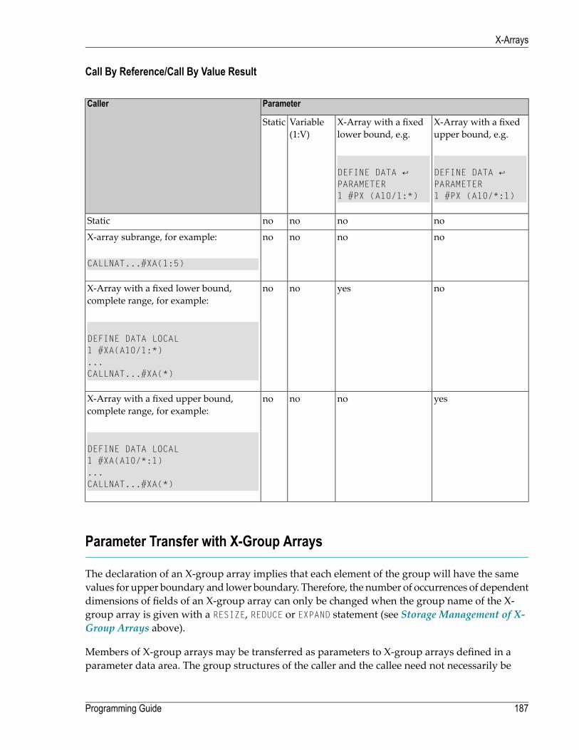
Call By Reference/Call By Value Result
ParameterCaller
X-Array with a fixedupper bound, e.g.
X-Array with a fixedlower bound, e.g.
Variable(1:V)
Static
DEFINE DATA ↩PARAMETER1 #PX (A10/*:1)
DEFINE DATA ↩PARAMETER1 #PX (A10/1:*)
nonononoStatic
nonononoX-array subrange, for example:
CALLNAT...#XA(1:5)
noyesnonoX-Array with a fixed lower bound,complete range, for example:
DEFINE DATA LOCAL1 #XA(A10/1:*)...CALLNAT...#XA(*)
yesnononoX-Array with a fixed upper bound,complete range, for example:
DEFINE DATA LOCAL1 #XA(A10/*:1)...CALLNAT...#XA(*)
Parameter Transfer with X-Group Arrays
The declaration of an X-group array implies that each element of the group will have the samevalues for upper boundary and lower boundary. Therefore, the number of occurrences of dependentdimensions of fields of an X-group array can only be changed when the group name of the X-group array is given with a RESIZE, REDUCE or EXPAND statement (see Storage Management of X-Group Arrays above).
Members of X-group arrays may be transferred as parameters to X-group arrays defined in aparameter data area. The group structures of the caller and the callee need not necessarily be
187Programming Guide
X-Arrays

identical. A RESIZE, REDUCE or EXPAND done by the callee is only possible as far as the X-group arrayof the caller stays consistent.
Example - Elements of X-Group Array Passed as Parameters:
Program:
DEFINE DATA LOCAL1 #X-GROUP-ARR1(1:*) /* (1:*)
2 #X-ARR1 (I4) /* (1:*)2 #X-ARR2 (I4) /* (1:*)
1 #X-GROUP-ARR2(1:*) /* (1:*)2 #X-ARR3 (I4) /* (1:*)2 #X-ARR4 (I4) /* (1:*)
END-DEFINE...CALLNAT ... #X-ARR1(*) #X-ARR4(*)...END
Subprogram:
DEFINE DATA PARAMETER1 #X-GROUP-ARR(1:*) /* (1:*)
2 #X-PAR1 (I4) /* (1:*)2 #X-PAR2 (I4) /* (1:*)
END-DEFINE...RESIZE ARRAY #X-GROUP-ARR to (1:5)...END
The RESIZE statement in the subprogram is not possible. It would result in an inconsistent numberof occurrences of the fields defined in the X-group arrays of the program.
X-Array of Dynamic Variables
An X-array of dynamic variables may be allocated by first specifying the number of occurrencesusing the EXPAND statement and then assigning a value to the previously allocated array occurrences.
Programming Guide188
X-Arrays
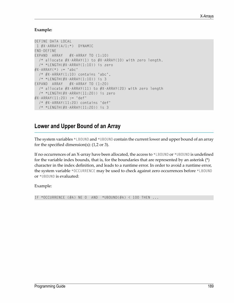
Example:
DEFINE DATA LOCAL1 #X-ARRAY(A/1:*) DYNAMICEND-DEFINEEXPAND ARRAY #X-ARRAY TO (1:10)
/* allocate #X-ARRAY(1) to #X-ARRAY(10) with zero length./* *LENGTH(#X-ARRAY(1:10)) is zero
#X-ARRAY(*) := 'abc'/* #X-ARRAY(1:10) contains 'abc',/* *LENGTH(#X-ARRAY(1:10)) is 3
EXPAND ARRAY #X-ARRAY TO (1:20)/* allocate #X-ARRAY(11) to #X-ARRAY(20) with zero length/* *LENGTH(#X-ARRAY(11:20)) is zero
#X-ARRAY(11:20) := 'def'/* #X-ARRAY(11:20) contains 'def'/* *LENGTH(#X-ARRAY(11:20)) is 3
Lower and Upper Bound of an Array
The system variables *LBOUND and *UBOUND contain the current lower and upper bound of an arrayfor the specified dimension(s): (1,2 or 3).
If no occurrences of an X-array have been allocated, the access to *LBOUND or *UBOUND is undefinedfor the variable index bounds, that is, for the boundaries that are represented by an asterisk (*)character in the index definition, and leads to a runtime error. In order to avoid a runtime error,the system variable *OCCURRENCEmay be used to check against zero occurrences before *LBOUNDor *UBOUND is evaluated:
Example:
IF *OCCURRENCE (#A) NE 0 AND *UBOUND(#A) < 100 THEN ...
189Programming Guide
X-Arrays

190

IV User-Defined Functions
191

192

23 User-Defined Functions
■ Introduction to User-Defined Functions .............................................................................................. 194■ Restrictions .................................................................................................................................. 195■ Function Call versus Subprogram Call ............................................................................................... 195■ Function Definition (DEFINE FUNCTION) ........................................................................................... 198■ Symbolic and Variable Function Call .................................................................................................. 198■ Function Result and Parameters ....................................................................................................... 198■ Explicit Prototype Definition (DEFINE PROTOTYPE) ............................................................................ 199■ Implicit (Automatic) Prototype Definition ............................................................................................. 199■ Prototype Cast (PT Clause) ............................................................................................................. 200■ Intermediate Result Definition (IR Clause) .......................................................................................... 200■ Combinations of Possible Prototype Definitions ................................................................................... 200■ Evaluation Sequence of Functions in Statements ................................................................................. 202■ Using a Function as a Statement ...................................................................................................... 204
193

Related topics:
■ Natural object type function■ Function Call■ Natural statements DEFINE FUNCTION, DEFINE PROTOTYPE
Introduction to User-Defined Functions
A user-defined function is a programming object of type function, containing Natural statementswhich implement a specific functional task. The invocation of a user-defined function (“functioncall”) usually has a number of parameters and returns a result.
The syntactical representation of a function call is the function name (call-name) followed by aspecial bracket notation containing the parameters, which is, for example: FCTNAME(<...>).
A function can be called from any place within a Natural statement where an operand is expectedwhich is only read, but notmodified. The result returned by the function is processed by the statementat the place where the function call is embedded, like a field containing the same value.
A function can also be called in a stand-alonemode, outside of anyNatural statement. In this case,the function result is not processed.
Usually, the result value returned by the function depends on the parameters provided with thefunction call. As well as with a Natural subprogram, a parameter can be definedwithin a functionas a “by reference”, “by value” or “by value result” field. This makes it possible to provide para-meter values in a function call which are only transfer compatible towhat is defined in the functiondefinition. Moreover, it allows you to exchange data between the calling object and the functionnot only via the function result, but also via parameters. The correctness of the parameter list andthe compatibility of the result value is checked at compilation, either by means of an existingcataloged function object or by means of a result and parameter layout definition described witha DEFINE PROTOTYPE statement.
All function calls used in aNatural statement are evaluated in a separate step before the statementexecution is started. They are evaluated in the same order in which they appear in the statement.
Programming Guide194
User-Defined Functions
Restrictions
At some places in a programming object, function calls cannot be used. This includes
■ positions where the operand value is changed by the Natural statement;■ all kinds of database calls (for example, FIND, READ);■ DEFINE DATA statement;■ IF BREAK statement;■ AT BREAK statement;■ array index expressions;■ Natural system functions (for example, AVER, SUM);■ parameters of a function call.
Function Call versus Subprogram Call
The following is a comparison of the characteristics of a function call with those of a subprogramcall.
■ What is similar?■ What is different?■ Example of a Function Call■ Example of a Subprogram Call
What is similar?
The following similarities exist between a function call and a subprogram call:
■ The programming code forming the routine logic is coded inside a separate object, either in afunction or a subprogram.
■ Parameters are defined in the object using a DEFINE DATA PARAMETER statement, with variouscommunication modes (for example, “by value”).
195Programming Guide
User-Defined Functions

What is different?
The following differences exist between a function call and a subprogram call:
■ A function call can be used at any position in a Natural statement where a read-only operandis possible (for exceptions, see Restrictions), whereas subprograms can be invoked only via theCALLNAT statement.
■ A function returns a result valuewhich can instantly be processed by the statement that includesthe function call. The use of a temporary variable is not required. A CALLNAT statement can onlyreturn data via its parameters. To process such a value with another statement, it needs to bedeclared as an explicit variable.
■ Parameters and the result of a function call are always verified if the called function alreadyexists at compilation time. Subprogram calls are checked only if the compiler option PCHECK isset to ON.
■ The name of a function, which is used to call the function, is definedwithin the DEFINE FUNCTIONstatement and may differ from the name of the object containing the function. Similar to sub-routines, the name of a function may have up to 32 characters. A subprogram is called by thename of the subprogram object. Therefore, themaximumname length is limited to 8 characters.
Example of a Function Call
The following example shows a program calling a function, and the function definition createdwith a DEFINE FUNCTION statement.
Program Calling the Function
** Example 'FUNCAX01': Calling a function (Program)*************************************************************************WRITE 'Function call' F#ADD(< 2,3 >) /* Function call.
/* No temporary variables needed.*END
Definition of Function F#ADD
** Example 'FUNCAX02': Calling a function (Function)************************************************************************DEFINE FUNCTION F#ADD
RETURNS #RESULT (I4)DEFINE DATA PARAMETER
1 #SUMMAND1 (I4) BY VALUE1 #SUMMAND2 (I4) BY VALUE
END-DEFINE/*#RESULT := #SUMMAND1 + #SUMMAND2/*
Programming Guide196
User-Defined Functions
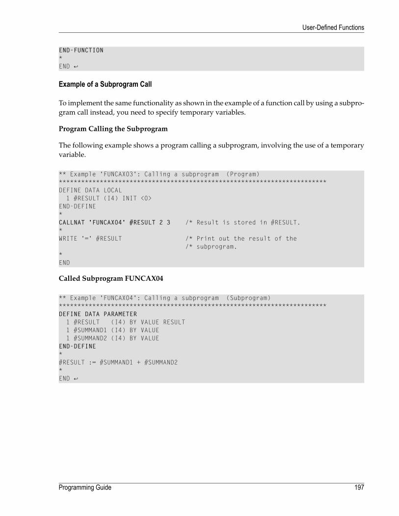
END-FUNCTION * END ↩
Example of a Subprogram Call
To implement the same functionality as shown in the example of a function call by using a subpro-gram call instead, you need to specify temporary variables.
Program Calling the Subprogram
The following example shows a program calling a subprogram, involving the use of a temporaryvariable.
** Example 'FUNCAX03': Calling a subprogram (Program)************************************************************************DEFINE DATA LOCAL
1 #RESULT (I4) INIT <0>END-DEFINE*CALLNAT 'FUNCAX04' #RESULT 2 3 /* Result is stored in #RESULT.*WRITE '=' #RESULT /* Print out the result of the
/* subprogram.*END
Called Subprogram FUNCAX04
** Example 'FUNCAX04': Calling a subprogram (Subprogram)************************************************************************DEFINE DATA PARAMETER
1 #RESULT (I4) BY VALUE RESULT1 #SUMMAND1 (I4) BY VALUE1 #SUMMAND2 (I4) BY VALUE
END-DEFINE * #RESULT := #SUMMAND1 + #SUMMAND2 * END ↩
197Programming Guide
User-Defined Functions

Function Definition (DEFINE FUNCTION)
A function is created in a separate Natural object of type function. It contains a single DEFINEFUNCTION statement, which defines the parameter interface, the result value and the program codeforming the operation logic.
Symbolic and Variable Function Call
There are two modes to call a function, either in a direct form or indirect form. In the direct form(denoted as “symbolic” function call), the function name specified in the call is exactly the nameof the function itself. In the indirect form (denoted as “variable” function call), the name specifiedin the function call is an alphanumeric variable with any name, which contains the name of thecalled function at runtime.
To define a variable function call, it is always necessary to use a DEFINE PROTOTYPE VARIABLEstatement. Otherwise, the function call is assumed to be a symbolic function call; this means, thename itself is regarded as the function name.
See Function Call for more details about this topic.
Function Result and Parameters
Usually, function calls are used within Natural statements instead of variables or constant values.Since the compiler strictly requires the layout of the operands involved, it is essential to get theformat, length and array structure of a function result. Moreover, if the parameter structure of afunction is known, the parameters supplied in a function call can be checked for correctness atcompilation time.
There are three options to provide this information
■ with a DEFINE PROTOTYPE statement;■ implicit by the existent object (cataloged version) of the called function, which is automaticallyloaded by the compiler if no DEFINE PROTOTYPE statement was found before;
■ with an explicit (IR=) clause specified in the function call.
The simplest way is certainly to use the second option, as it always takes the information from theobject which is called at runtime. However, this is only possible if the cataloged object of the calledfunction is available. If a function is called with a variable function call, via a variable containingthe function name, the name of the function object is unknown and as a consequence cannot be
Programming Guide198
User-Defined Functions

identified and loaded. In this case a DEFINE PROTOTYPE statement can be used to describe thefunction interface. The first two options comprise a full validation of the result and the parameters.
If neither a DEFINE PROTOTYPE statement nor the existent object of a function call is available, twocasting options can be used in a function call. These are
■ (IR=) to specify the function result format/length/array structure. This option does not incorporateany parameter checks.
■ (PT=) to use a previously defined prototype with a name other than the function name.
Explicit Prototype Definition (DEFINE PROTOTYPE)
To specify the interface of a certain function, a DEFINE PROTOTYPE statement can be used. Thisstatement defines the layout of the parameters, which are to be passed in a function call, and theformat/length of the result field returned by the function. Furthermore, it indicates whether afunction call is a “symbolic” or a “variable” function call.
When a function call was found, Natural tries to locate a prototype with the same name as theused function name. If such a prototype is found, the function result and parameter layouts of thisprototype are used to resolve the function call. Especially, the decision on the function call mode(“symbolic” or “variable”) is made at this place.
Implicit (Automatic) Prototype Definition
If a function call is resolved in a program, the compiler searches for a DEFINE PROTOTYPE statementwith the function name, which has been defined before. If such a statement cannot be found,Natural tries to load the called function into the buffer pool. If successful, the function layout ofthe result and and the parameters is extracted from the object data and kept as if it was providedby an explicit DEFINE PROTOTYPE statement for this function. This manner of use is denoted asautomatic prototype definition. It assures great conformity between the interface definition (at compiletime) and the passing accuracy at runtime.
199Programming Guide
User-Defined Functions

Prototype Cast (PT Clause)
In order to get the interface layout of a called function, Natural tries to locate a DEFINE PROTOTYPEstatement with the same name as the function identifier. If such a statement is not available, andthe called function object cannot be loaded (see Implicit (Automatic) Prototype Definition ), a(PT=) clause can be specified in the function call. If such a clause is applied, the DEFINE PROTOTYPEstatementwith the referenced name (which is different from the function name) is used to describethe function result and to validate the parameters.
Example:
#I := #MULT(<(PT=#ADD) 2 , 3>)
In this example, the function #MULT is called, but the result and parameter layouts are used froma prototype whose name is #ADD.
Intermediate Result Definition (IR Clause)
Usually, the function result is specified by a DEFINE PROTOTYPE statement, which is either codedexplicitly or will be created automatically with the function object (see Implicit (Automatic) Pro-totype Definition ). If such a definition is not available, the result layout can be specified by usingthe (IR=) clause in the function call. If this clause is used, it determines which format/length thecompiler should use for the result field in the statement generation. This clause can also be specifiedif the prototype definition is available for a function call. In this case, the result layout in the pro-totype is overruled by the (IR=) clause specification; the parameter checks, however, are performedaccording to the prototype definition.
Combinations of Possible Prototype Definitions
In order to resolve a function call, the compiler needs information on
■ the function call mode (symbolic or variable);■ the layout (format/length) of the function result;■ the layout (format/length) of the function parameters.
Different options allow you to provide this data, which are the explicit prototype definition, theimplicit prototype definition, the (PT=) option, and the (IR=) option. But which one has an effectif multiple of these clauses are used?
Programming Guide200
User-Defined Functions

A function call is used as a variable function call if there is a related prototype with the samename,which contains a VARIABLE clause. In all other cases, the function call is treated as a symbolicfunction call.
The result is determined in the following order:
■ the definition provided in (IR=), if this clause is specified;■ the RETURNS definition in the prototype referenced in (PT=), if this clause is specified;■ the explicit prototype definition (DEFINE PROTOTYPE) with the same name as used in the functioncall, if it exists;
■ the implicit prototype definition,which is loaded automatically from the existing function object.
If none of these options applies, a syntax error is raised.
The parameter checks are performed according to the definition in:
■ the prototype definition referenced in (PT=), if this clause is specified;■ the explicit prototype definition (DEFINE PROTOTYPE) with the same name as used in the functioncall, if it exists;
■ the implicit prototype definition,which is loaded automatically from the existing function object.
If none of these options applies, the parameter validation is not performed. This allows you tosupply any number and layout of parameters in the function call, without receiving a syntax error.
Example with Multiple Definitions in a Function Call
Program:
** Example 'FUNCBX01': Declare result value and parameters (Program)*************************************************************************DEFINE DATA LOCAL
1 #PROTO-NAME (A20)1 #PARM1 (I4)1 #PARM2 (I4)
END-DEFINE*DEFINE PROTOTYPE VARIABLE #PROTO-NAME
RETURNS (I4)DEFINE DATA PARAMETER
1 #P1 (I4) BY VALUE OPTIONAL1 #P2 (I4) BY VALUE
END-DEFINEEND-PROTOTYPE*#PROTO-NAME := 'F#MULTI'#PARM1 := 3
201Programming Guide
User-Defined Functions

#PARM2 := 5*WRITE #PROTO-NAME(<#PARM1, #PARM2>)WRITE #PROTO-NAME(<1X ,5>)*WRITE F#MULTI(<(PT=#PROTO-NAME) #PARM1,#PARM2>)*WRITE F#MULTI(<(IR=N20) #PARM1, #PARM2>)*END
Function F#MULTI:
** Example 'FUNCBX02': Declare result value and parameters (Function)************************************************************************DEFINE FUNCTION F#MULTI
RETURNS #RESULT (I4) BY VALUEDEFINE DATA PARAMETER
1 #FACTOR1 (I4) BY VALUE OPTIONAL1 #FACTOR2 (I4) BY VALUE
END-DEFINE/*IF #FACTOR1 SPECIFIED
#RESULT := #FACTOR1 * #FACTOR2ELSE
#RESULT := #FACTOR2 * 10END-IF/*
END-FUNCTION * END ↩
Evaluation Sequence of Functions in Statements
Instead of operands, function calls can be used directly in statements. However, this is only allowedwith operands which are only read, but not modified by the statement.
All function calls are evaluated before the statement execution starts. The returned result valuesare stored in temporary fields and passed to the statement. The functions are executed in the sameorder in which they appear in the statement. If a function call has parameters which are modifiedby the function execution, you should consider that this can influence the statement result. Thismay apply if the same parameter is used at another place in the same statement.
Example:
Before the COMPUTE statement is started, variable #I has the value 1. In a first step, function F#RETURNis executed. This changes #I to value 2 and returns the same value as the function result. After
Programming Guide202
User-Defined Functions
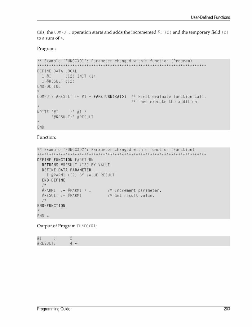
this, the COMPUTE operation starts and adds the incremented #I (2) and the temporary field (2)to a sum of 4.
Program:
** Example 'FUNCCX01': Parameter changed within function (Program)************************************************************************DEFINE DATA LOCAL
1 #I (I2) INIT <1>1 #RESULT (I2)
END-DEFINE*COMPUTE #RESULT := #I + F#RETURN(<#I>) /* First evaluate function call,
/* then execute the addition.*WRITE '#I :' #I /
'#RESULT:' #RESULT*END
Function:
** Example 'FUNCCX02': Parameter changed within function (Function)************************************************************************DEFINE FUNCTION F#RETURN
RETURNS #RESULT (I2) BY VALUEDEFINE DATA PARAMETER
1 #PARM1 (I2) BY VALUE RESULTEND-DEFINE/*#PARM1 := #PARM1 + 1 /* Increment parameter.#RESULT := #PARM1 /* Set result value./*
END-FUNCTION * END ↩
Output of Program FUNCCX01:
#I : 2 #RESULT: 4 ↩
203Programming Guide
User-Defined Functions

Using a Function as a Statement
A function can also be called stand-alone, without being embedded in other statements. In thiscase, the function return value is completely ignored.
If such an execution mode is desired, only the function call is coded, which then stands for astatement. In order to prevent an unwanted link to the previous statement in the source code, asemicolon must be used to explicitly separate the function call from this statement.
Example:
Program:
** Example 'FUNCDX01': Using a function as a statement (Program)************************************************************************DEFINE DATA LOCAL
1 #A (I4) INIT <1>1 #B (I4) INIT <2>
END-DEFINE**WRITE 'Write:' #A #BF#PRINT-ADD(< 2,3 >) /* Function call belongs to operand list
/* immediately preceding it.*WRITE // '*************************' //*WRITE 'Write:' #A #B; /* Semicolon separates operands and function.F#PRINT-ADD(< 2,3 >) /* Function call does not belong to the
/* operand list.*END
Function:
** Example 'FUNCDX02': Using a function as a statement (Function)************************************************************************DEFINE FUNCTION F#PRINT-ADD
RETURNS (I4)DEFINE DATA PARAMETER
1 #SUMMAND1 (I4) BY VALUE1 #SUMMAND2 (I4) BY VALUE
END-DEFINE/*F#PRINT-ADD := #SUMMAND1 + #SUMMAND2 /* Result of function call.WRITE 'Function call:' F#PRINT-ADD/*
END-FUNCTION
Programming Guide204
User-Defined Functions

* END ↩
Output of Program FUNCDX01:
Function call: 5 Write: 1 2 5
*************************
Write: 1 2 Function call: 5 ↩
205Programming Guide
User-Defined Functions

206

V Accessing Data in a Database
This part describes various aspects of accessing data in a database with Natural.
Natural and Database Access
Accessing Data in an Adabas Database
Accessing Data in an SQL Database
Accessing Data in a Tamino Database
207

208

24 Natural and Database Access
■ Database Management Systems Supported by Natural ......................................................................... 210■ Profile Parameters Influencing Database Access ................................................................................. 211■ Access through Data Definition Modules ............................................................................................ 211■ Natural's Data Manipulation Language ............................................................................................... 212■ Natural's Special SQL Statements ..................................................................................................... 213
209
This chapter gives an overview of the facilities that Natural provides for accessing different typesof database management systems.
Database Management Systems Supported by Natural
Natural offers specific database interfaces for the following types of databasemanagement systems(DBMS):
■ Nested-relational DBMS (Adabas)■ SQL-type DBMS (Oracle, Sybase, Informix, MS SQL Server)■ XML-type DBMS (Tamino)
The following topics are covered below:
■ Adabas■ Tamino■ SQL Databases
Adabas
Via its integratedAdabas interface, Natural can access Adabas databases either on a localmachineor on remote computers. For remote access, an additional routing and communication softwaresuch as Entire Net-Work is necessary. In any case, the type of host machine running the Adabasdatabase is transparent for the Natural user.
Tamino
Natural for Tamino offers the possibility to access a Tamino database server on a local machineor on a remote host using a native HTTP protocol. The Tamino database can be accessed in thesame manner as data access is done with Adabas or SQL databases.
SQL Databases
Natural acesses SQL database systems via Entire Access, a generic interface and routing softwarethat supports various SQL database management systems such as Oracle, MS SQL Server orstandardized ODBC connections. For a complete overview of the SQL database managementsystems and platforms supported, refer to the Entire Access documentation. Information on Nat-ural configuration aspects is contained in the document Natural and Entire Access.
Programming Guide210
Natural and Database Access

Profile Parameters Influencing Database Access
There are variousNatural profile parameters to define howNatural handles the access to databases.
For an overview of these profile parameters, see the section Database Management in Overview ofProfile Parameters in the Configuration Utility documentation.
For a detailed parameter description, refer to the corresponding section in the Parameter Reference.
Access through Data Definition Modules
To enable convenient and transparent access to the different database management systems, aspecial object, the “data definition module” (DDM), is used in Natural. This DDM establishes theconnection between the Natural data structures and the data structures in the database system tobe used. Such a database structuremight be a table in an SQLdatabase, a file in anAdabas databaseor a doctype in a Tamino database.Hence, theDDMhides the real structure of the database accessedfrom the Natural application. DDMs are created using the Natural DDM editor.
Natural is capable of accessing multiple types of databases (Adabas, Tamino, RDBMS) fromwithin a single application by using references to DDMs that represent the specific data structuresin the specific database system. The diagrambelow shows an application that connects to differenttypes of database.
211Programming Guide
Natural and Database Access

Natural's Data Manipulation Language
Natural has a built-in datamanipulation language (DML) that allowsNatural applications to accessall database systems supported byNatural using the same language statements such as FIND, READ,STORE or DELETE. These statements can be used in a Natural application without knowing the typeof database that is going to be accessed.
Natural determines the real type of database system from its configuration files and translates theDML statements into database-specific commands; that is, it generates direct commands forAdabas, SQL statement strings and host variable structures for SQLdatabases andXQuery requestsfor a Tamino database.
Because some of the Natural DML statements provide functionality that cannot be supported forall database types, the use of this functionality is restricted to specific database systems. Please,note the corresponding database-specific considerations in the statements documentation.
Programming Guide212
Natural and Database Access

Natural's Special SQL Statements
In addition to the “normal” Natural DML statements, Natural provides a set of SQL statementsfor a more specific use in conjunction with SQL database systems; see SQL Statements Overview(in the Statements documentation).
Flexible SQL and facilities forworkingwith stored procedures complete the set of SQL commands.These statements can be used for SQL database access only and are not valid for Adabas or othernon-SQL-databases.
213Programming Guide
Natural and Database Access

214

25 Accessing Data in an Adabas Database
■ Adabas Database Management Interfaces ADA and ADA2 .................................................................... 216■ Data Definition Modules - DDMs ....................................................................................................... 216■ Database Arrays ............................................................................................................................ 218■ Defining a Database View ............................................................................................................... 224■ Statements for Database Access ...................................................................................................... 227■ Multi-Fetch Clause ......................................................................................................................... 239■ Database Processing Loops ............................................................................................................ 240■ Database Update - Transaction Processing ......................................................................................... 246■ Selecting Records Using ACCEPT/REJECT ....................................................................................... 253■ AT START/END OF DATA Statements ............................................................................................... 257■ Unicode Data ................................................................................................................................ 259
215

This chapter describes various aspects of accessing data in an Adabas database with Natural.
Adabas Database Management Interfaces ADA and ADA2
Natural'sAdabas databasemanagement interfacesADAandADA2are considereddistinct databaseinterfaces like, for example, ADA and SQL.
Database type ADA is Natural's default interface to Adabas databases. It is the appropriate choiceif new Adabas functionality as introduced with Adabas Version 6 on Open Systems and AdabasVersion 8 on mainframes is not concerned.
Database type ADA2 is provided as an extended interface to Adabas databases as of Version 6 onOpen Systems and Adabas as of Version 8 on mainframes. In particular, it supports Adabas LAfields, Adabas large object fields and extended Adabas buffer lengths. The support of Adabas LAand large object fields implies the use of Natural format (A) DYNAMIC in a view definition, thesupport of extended Adabas buffer lengths enables the definition of view sizes that exceed 64 KB.For further information, refer to Defining a Database View.
Database type ADA2 does not supportmulti-fetch processing. Corresponding global and localdefinitions are ignored at runtime.
SoftwareAGproductswhich have their own systemfiles require a corresponding physical databaseof database type ADA.
Natural objects that were compiled with database type ADA can be executed in an environmentwhere the corresponding Adabas database is defined as database type ADA2.
Data Definition Modules - DDMs
For Natural to be able to access a database file, a logical definition of the physical database file isrequired. Such a logical file definition is called a data definition module (DDM).
This section covers the following topics:
■ Use of Data Definition Modules■ Maintaining DDMs
Programming Guide216
Accessing Data in an Adabas Database

■ Listing/Displaying DDMs
Use of Data Definition Modules
The data definitionmodule contains information about the individual fields of the file - informationwhich is relevant for the use of these fields in a Natural program. A DDM constitutes a logicalview of a physical database file.
For each physical file of a database, one or more DDMs can be defined. And for each DDM oneor more data views can be defined as described View Definition in the DEFINE DATA statementdocumentation and explained in the section Defining a Database View.
DDMs are defined by the Natural administrator with Predict (or, if Predict is not available, withthe corresponding Natural function).
217Programming Guide
Accessing Data in an Adabas Database

Maintaining DDMs
For each database field, a DDM contains the database-internal field name as well as the “external”field name, that is, the name of the field as used in a Natural program. Moreover, the formats andlengths of the fields are defined in the DDM, as well as various specifications that are used whenthe fields are output with a DISPLAY or WRITE statement (column headings, edit masks, etc.).
For the field attributes defined in a DDM, refer toUsing the DDMEditor in the sectionDDMEditorof the Editors documentation.
Listing/Displaying DDMs
If you do not know the name of the DDM you want, you can use the system command LIST VIEWto get a list of all existing DDMs that are available in the current library. From the list, you canthen select a DDM for display.
MeaningSystem command
Displays a list of all views (DDMs).LIST VIEW
If you specify a single view name, the specified view will be displayed. For theview-name you can use asterisk notation to display a list of all views (*) or acertain range of views (for example: A*).
LIST VIEW view-name
Database Arrays
Adabas supports array structures within the database in the form of multiple-value fields andperiodic groups.
This section covers the following topics:
■ Multiple-Value Fields■ Periodic Groups■ Referencing Multiple-Value Fields and Periodic Groups■ Multiple-Value Fields within Periodic Groups■ Referencing Multiple-Value Fields within Periodic Groups
Programming Guide218
Accessing Data in an Adabas Database

■ Referencing the Internal Count of a Database Array
Multiple-Value Fields
A multiple-value field is a field which can have more than one value (up to 65534, depending onthe Adabas version and definition of the FDT) within a given record.
219Programming Guide
Accessing Data in an Adabas Database

Example:
Assuming that the above is a record in an employees file, the first field (Name) is an elementaryfield, which can contain only one value, namely the name of the person; whereas the second field(Languages), which contains the languages spoken by the person, is a multiple-value field, as aperson can speak more than one language.
Periodic Groups
Aperiodic group is a group of fields (whichmay be elementary fields and/ormultiple-value fields)that may have more than one occurrence (up to 65534, depending on the Adabas version anddefinition of the field definition table (FDT)) within a given record.
The different values of a multiple-value field are usually called “occurrences”; that is, the numberof occurrences is the number of values which the field contains, and a specific occurrence meansa specific value. Similarly, in the case of periodic groups, occurrences refer to a group of values.
Programming Guide220
Accessing Data in an Adabas Database

Example:
Assuming that the above is a record in a vehicles file, the first field (Name) is an elementary fieldwhich contains the name of a person; Cars is a periodic group which contains the automobilesowned by that person. The periodic group consists of three fields which contain the registrationnumber, make andmodel of each automobile. Each occurrence of Cars contains the values for oneautomobile.
Referencing Multiple-Value Fields and Periodic Groups
To reference one or more occurrences of a multiple-value field or a periodic group, you specifyan “index notation” after the field name.
Examples:
The following examples use the multiple-value field LANGUAGES and the periodic group CARS fromthe previous examples.
The various values of the multiple-value field LANGUAGES can be referenced as follows.
221Programming Guide
Accessing Data in an Adabas Database

ExplanationExample
References the first value (SPANISH).LANGUAGES (1)
The value of the variable X determines the value to be referenced.LANGUAGES (X)
References the first three values (SPANISH, CATALAN and FRENCH).LANGUAGES (1:3)
References the sixth to tenth values.LANGUAGES (6:10)
The values of the variables X and Y determine the values to be referenced.LANGUAGES (X:Y)
The various occurrences of the periodic group CARS can be referenced in the same manner:
ExplanationExample
References the first occurrence (B-123ABC/SEAT/IBIZA).CARS (1)
The value of the variable X determines the occurrence to be referenced.CARS (X)
References the first two occurrences (B-123ABC/SEAT/IBIZA and B-999XYZ/VW/GOLF).CARS (1:2)
References the fourth to seventh occurrences.CARS (4:7)
The values of the variables X and Y determine the occurrences to be referenced.CARS (X:Y)
Multiple-Value Fields within Periodic Groups
An Adabas array can have up to two dimensions: a multiple-value field within a periodic group.
Programming Guide222
Accessing Data in an Adabas Database

Example:
Assuming that the above is a record in a vehicles file, the first field (Name) is an elementary fieldwhich contains the name of a person; Cars is a periodic group, which contains the automobilesowned by that person. This periodic group consists of three fields which contain the registrationnumber, servicing dates and make of each automobile. Within the periodic group Cars, the fieldServicing is a multiple-value field, containing the different servicing dates for each automobile.
Referencing Multiple-Value Fields within Periodic Groups
To reference one ormore occurrences of amultiple-value fieldwithin a periodic group, you specifya “two-dimensional” index notation after the field name.
Examples:
The following examples use the multiple-value field SERVICINGwithin the periodic group CARSfrom the example above. The various values of themultiple-value field can be referenced as follows:
223Programming Guide
Accessing Data in an Adabas Database

ExplanationExample
References the first value of SERVICING in the first occurrence of CARS(31-05-97).
SERVICING (1,1)
References the first value of SERVICING in the first five occurrences of CARS.SERVICING (1:5,1)
References the first ten values of SERVICING in the first five occurrences ofCARS.
SERVICING (1:5,1:10)
Referencing the Internal Count of a Database Array
It is sometimes necessary to reference a multiple-value field or a periodic groupwithout knowinghow many values/occurrences exist in a given record. Adabas maintains an internal count of thenumber of values in each multiple-value field and the number of occurrences of each periodicgroup. This count may be read in a READ statement by specifying C* immediately before the fieldname.
The count is returned in format/length N3. See Referencing the Internal Count for a DatabaseArray for further details.
ExplanationExample
Returns the number of values of the multiple-value field LANGUAGES.C*LANGUAGES
Returns the number of occurrences of the periodic group CARS.C*CARS
Returns the number of values of the multiple-value field SERVICING in the firstoccurrence of a periodic group (assuming that SERVICING is a multiple-value fieldwithin a periodic group.)
C*SERVICING (1)
Defining a Database View
To be able to use database fields in a Natural program, you must specify the fields in a databaseview.
In the view, you specify the name of the data definition module (see Data Definition Modules -DDMs) from which the fields are to be taken, and the names of the database fields themselves(that is, their long names, not their database-internal short names).
The view may comprise an entire DDM or only a subset of it. The order of the fields in the viewneed not be the same as in the underlying DDM.
As described in the section Statements forDatabaseAccess, the viewname is used in the statementsREAD, FIND, HISTOGRAM to determine which database is to be accessed.
For further information on the complete syntax of the viewdefinition option or on the definition/re-definition of a group of fields, see View Definition in the description of the DEFINE DATA statementin the Statements documentation.
Programming Guide224
Accessing Data in an Adabas Database
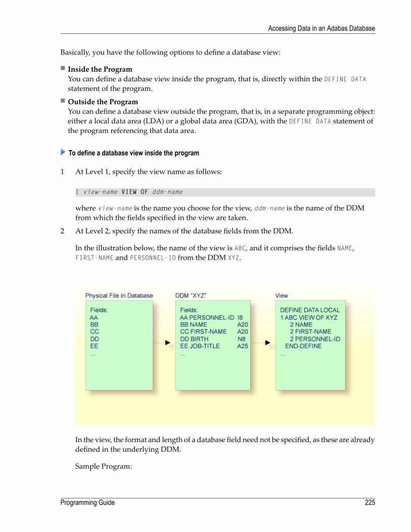
Basically, you have the following options to define a database view:
■ Inside the ProgramYou can define a database view inside the program, that is, directly within the DEFINE DATAstatement of the program.
■ Outside the ProgramYou can define a database view outside the program, that is, in a separate programming object:either a local data area (LDA) or a global data area (GDA), with the DEFINE DATA statement ofthe program referencing that data area.
To define a database view inside the program
1 At Level 1, specify the view name as follows:
1 view-name VIEW OF ddm-name
where view-name is the name you choose for the view, ddm-name is the name of the DDMfrom which the fields specified in the view are taken.
2 At Level 2, specify the names of the database fields from the DDM.
In the illustration below, the name of the view is ABC, and it comprises the fields NAME,FIRST-NAME and PERSONNEL-ID from the DDM XYZ.
In the view, the format and length of a database field need not be specified, as these are alreadydefined in the underlying DDM.
Sample Program:
225Programming Guide
Accessing Data in an Adabas Database

In this example, the view-name is VIEWEMP, and the ddm-name is EMPLOYEES, and the names ofthe database fields taken from the DDM are NAME, FIRST-NAME and PERSONNEL-ID.
DEFINE DATA LOCAL1 VIEWEMP VIEW OF EMPLOYEES
2 NAME2 FIRST-NAME2 PERSONNEL-ID
1 #VARI-A (A20)1 #VARI-B (N3.2)1 #VARI-C (I4)END-DEFINE...
To define a database view outside the program
1 In the program, specify:
DEFINE DATA LOCALUSING <data-area-name>
END-DEFINE...
where data-area-name is the name you choose for the local or global data area, for example,LDA39.
2 In the data area to be referenced:
1. At Level 1 in the Name column, specify the name you choose for the view, and in theMiscellaneous column, the name of the DDM from which the fields specified in the vieware taken.
2. At Level 2, specify the names of the database fields from the DDM.
Example LDA39:
In this example, the view name is VIEWEMP, the DDM name is EMPLOYEES, and the namesof the database fields taken from the DDM are PERSONNEL-ID, FIRST-NAME and NAME.
I T L Name F Length Miscellaneous ↩ All -- -------------------------------- - ---------- -------------------------> V 1 VIEWEMP EMPLOYEES ↩ 2 PERSONNEL-ID A 8 ↩ 2 FIRST-NAME A 20 ↩ 2 NAME A 20 ↩
Programming Guide226
Accessing Data in an Adabas Database

1 #VARI-A A 20 ↩ 1 #VARI-B N 3.2 ↩ 1 #VARI-C I 4 ↩ ↩
Considerations Concerning Databases of Type ADA2
With databases of type ADA2 (specified in the table DBMSAssignments in the ConfigurationUtility,see Database Management System Assignments in the Configuration Utility documentation), the fol-lowing applies:
■ If large alphanumeric (LA) or large object (LOB) fields (Adabas LA/LB option) are to be used,these fields can be specifiedwithin the viewdefinitionwith both fixed format/length, for example,A20 or U20, and dynamic format/length, for example, (A)DYNAMIC or U(DYNAMIC).
■ Length indicator fields L@... can also be specifiedwithin views if they are related to LA or LOBfields.
Statements for Database Access
To read data from a database, the following statements are available:
MeaningStatement
Select a range of records from a database in a specified sequence.READ
Select from a database those records which meet a specified search criterion.FIND
Read only the values of one database field, or determine the number of records which meeta specified search criterion.
HISTOGRAM
READ Statement
The following topics are covered:
■ Use of READ Statement■ Basic Syntax of READ Statement■ Example of READ Statement■ Limiting the Number of Records to be Read■ STARTING/ENDING Clauses■ WHERE Clause
227Programming Guide
Accessing Data in an Adabas Database

■ Further Example of READ Statement
Use of READ Statement
The READ statement is used to read records from a database. The records can be retrieved from thedatabase
■ in the order in which they are physically stored in the database (READ IN PHYSICAL SEQUENCE),or
■ in the order of Adabas Internal Sequence Numbers (READ BY ISN), or■ in the order of the values of a descriptor field (READ IN LOGICAL SEQUENCE).
In this document, only READ IN LOGICAL SEQUENCE is discussed, as it is the most frequently usedform of the READ statement.
For information on the other two options, please refer to the description of the READ statement inthe Statements documentation.
Basic Syntax of READ Statement
The basic syntax of the READ statement is:
READ view IN LOGICAL SEQUENCE BY descriptor
or shorter:
READ view LOGICAL BY descriptor
- where
is the name of a view defined in the DEFINE DATA statement and as explained in Defininga Database View.
view
is the name of a database field defined in that view. The values of this field determine theorder in which the records are read from the database.
descriptor
If you specify a descriptor, you need not specify the keyword LOGICAL:
READ view BY descriptor
If you do not specify a descriptor, the recordswill be read in the order of values of the field definedas default descriptor (under Default Sequence) in theDDM. However, if you specify no descriptor,you must specify the keyword LOGICAL:
Programming Guide228
Accessing Data in an Adabas Database
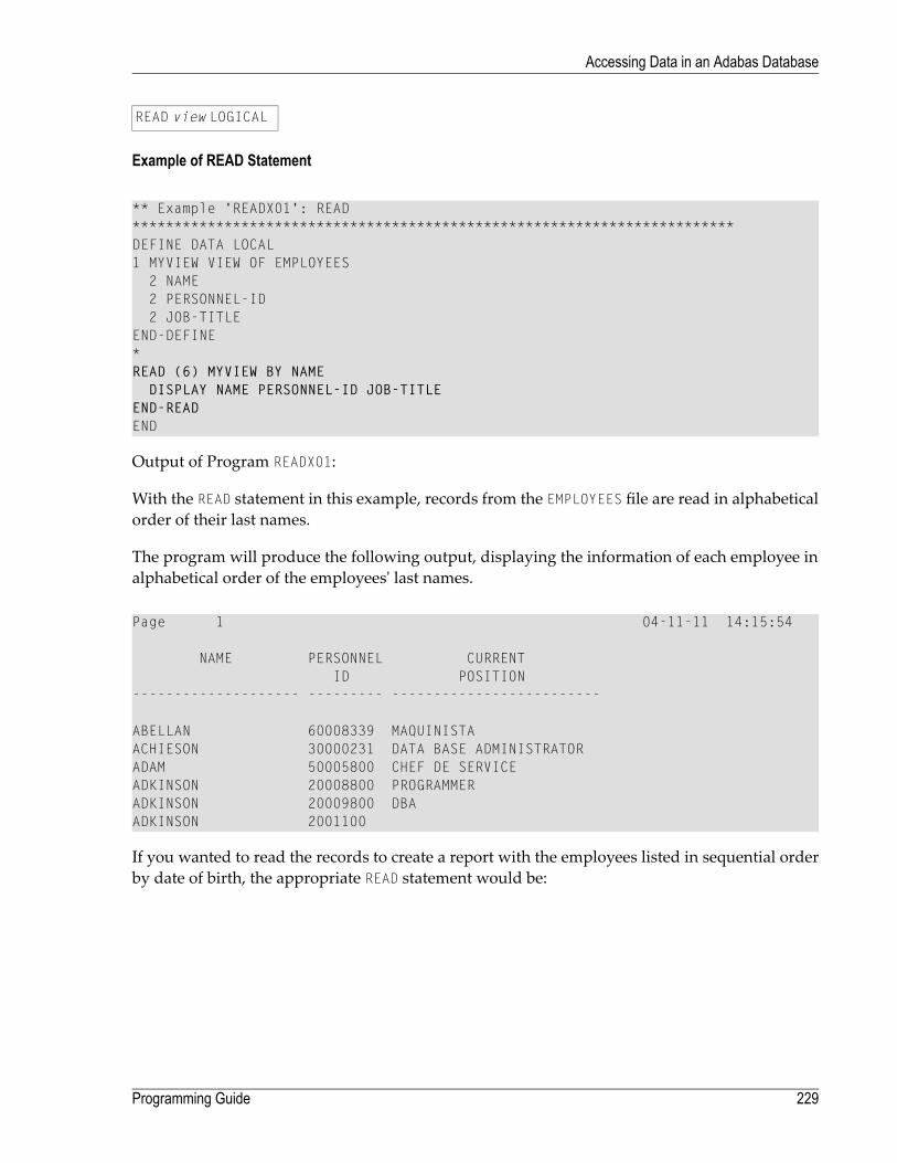
READ view LOGICAL
Example of READ Statement
** Example 'READX01': READ************************************************************************DEFINE DATA LOCAL1 MYVIEW VIEW OF EMPLOYEES
2 NAME2 PERSONNEL-ID2 JOB-TITLE
END-DEFINE*READ (6) MYVIEW BY NAME
DISPLAY NAME PERSONNEL-ID JOB-TITLEEND-READEND
Output of Program READX01:
With the READ statement in this example, records from the EMPLOYEES file are read in alphabeticalorder of their last names.
The program will produce the following output, displaying the information of each employee inalphabetical order of the employees' last names.
Page 1 04-11-11 14:15:54
NAME PERSONNEL CURRENTID POSITION
-------------------- --------- -------------------------
ABELLAN 60008339 MAQUINISTAACHIESON 30000231 DATA BASE ADMINISTRATORADAM 50005800 CHEF DE SERVICEADKINSON 20008800 PROGRAMMERADKINSON 20009800 DBAADKINSON 2001100
If you wanted to read the records to create a report with the employees listed in sequential orderby date of birth, the appropriate READ statement would be:
229Programming Guide
Accessing Data in an Adabas Database

READ MYVIEW BY BIRTH
You can only specify a field which is defined as a “descriptor” in the underlyingDDM (it can alsobe a subdescriptor, superdescriptor, hyperdescriptor or phonetic descriptor or a non-descriptor).
Limiting the Number of Records to be Read
As shown in the previous example program, you can limit the number of records to be read byspecifying a number in parentheses after the keyword READ:
READ (6) MYVIEW BY NAME
In that example, the READ statement would read no more than 6 records.
Without the limit notation, the above READ statement would read all records from the EMPLOYEESfile in the order of last names from A to Z.
STARTING/ENDING Clauses
The READ statement also allows you to qualify the selection of records based on the value of adescriptor field. With an EQUAL TO/STARTING FROM option in the BY clause, you can specify thevalue at which reading should begin. (Instead of using the keyword BY, you may specify thekeyword WITH, which would have the same effect). By adding a THRU/ENDING AT option, you canalso specify the value in the logical sequence at which reading should end.
For example, if youwanted a list of those employees in the order of job titles startingwith TRAINEEand continuing on to Z, you would use one of the following statements:
READ MYVIEW WITH JOB-TITLE = 'TRAINEE'READ MYVIEW WITH JOB-TITLE STARTING FROM 'TRAINEE'READ MYVIEW BY JOB-TITLE = 'TRAINEE'READ MYVIEW BY JOB-TITLE STARTING FROM 'TRAINEE'
Note that the value to the right of the equal sign (=) or STARTING FROM option must be enclosed inapostrophes. If the value is numeric, this text notation is not required.
The sequence of records to be read can be evenmore closely specified by adding an end limit witha THRU/ENDING AT clause.
To read just the records with the job title TRAINEE, you would specify:
Programming Guide230
Accessing Data in an Adabas Database

READ MYVIEW BY JOB-TITLE STARTING FROM 'TRAINEE' THRU 'TRAINEE'READ MYVIEW WITH JOB-TITLE EQUAL TO 'TRAINEE'
ENDING AT 'TRAINEE'
To read just the records with job titles that begin with A or B, you would specify:
READ MYVIEW BY JOB-TITLE = 'A' THRU 'C'READ MYVIEW WITH JOB-TITLE STARTING FROM 'A' ENDING AT 'C'
The values are read up to and including the value specified after THRU/ENDING AT. In the two ex-amples above, all records with job titles that begin with A or B are read; if there were a job title C,this would also be read, but not the next higher value CA.
WHERE Clause
The WHERE clause may be used to further qualify which records are to be read.
For instance, if you wanted only those employees with job titles starting from TRAINEEwho arepaid in US currency, you would specify:
READ MYVIEW WITH JOB-TITLE = 'TRAINEE'WHERE CURR-CODE = 'USD'
The WHERE clause can also be used with the BY clause as follows:
READ MYVIEW BY NAMEWHERE SALARY = 20000
The WHERE clause differs from the BY clause in two respects:
■ The field specified in the WHERE clause need not be a descriptor.■ The expression following the WHERE option is a logical condition.
The following logical operators are possible in a WHERE clause:
=EQEQUAL
¬=NENOT EQUAL TO
<LTLESS THAN
<=LELESS THAN OR EQUAL TO
>GTGREATER THAN
>=GEGREATER THAN OR EQUAL TO
The following program illustrates the use of the STARTING FROM, ENDING AT and WHERE clauses:
231Programming Guide
Accessing Data in an Adabas Database

** Example 'READX02': READ (with STARTING, ENDING and WHERE clause)************************************************************************DEFINE DATA LOCAL1 MYVIEW VIEW OF EMPLOYEES
2 NAME2 JOB-TITLE2 INCOME (1:2)
3 CURR-CODE3 SALARY3 BONUS (1:1)
END-DEFINE*READ (3) MYVIEW WITH JOB-TITLESTARTING FROM 'TRAINEE' ENDING AT 'TRAINEE'
WHERE CURR-CODE (*) = 'USD'DISPLAY NOTITLE NAME / JOB-TITLE 5X INCOME (1:2)SKIP 1
END-READEND
Output of Program READX02:
NAME INCOMECURRENT
POSITION CURRENCY ANNUAL BONUSCODE SALARY
------------------------- -------- ---------- ----------
SENKO USD 23000 0TRAINEE USD 21800 0
BANGART USD 25000 0TRAINEE USD 23000 0
LINCOLN USD 24000 0TRAINEE USD 22000 0
Further Example of READ Statement
See the following example program:
■ READX03 - READ statement
Programming Guide232
Accessing Data in an Adabas Database

FIND Statement
The following topics are covered:
■ Use of FIND Statement■ Basic Syntax of FIND Statement■ Limiting the Number of Records to be Processed■ WHERE Clause■ Example of FIND Statement with WHERE Clause■ IF NO RECORDS FOUND Condition■ Further Examples of FIND Statement
Use of FIND Statement
The FIND statement is used to select from a database those records which meet a specified searchcriterion.
Basic Syntax of FIND Statement
The basic syntax of the FIND statement is:
FIND RECORDS IN view WITH field = value
or shorter:
FIND view WITH field = value
- where
is the name of a view as defined in the DEFINE DATA statement and as explained in Defining aDatabase View.
view
is the name of a database field as defined in that view.field
You can only specify a fieldwhich is defined as a “descriptor” in the underlyingDDM (it canalso be a subdescriptor, superdescriptor, hyperdescriptor or phonetic descriptor).
For the complete syntax, refer to the FIND statement documentation.
233Programming Guide
Accessing Data in an Adabas Database

Limiting the Number of Records to be Processed
In the same way as with the READ statement described above, you can limit the number of recordsto be processed by specifying a number in parentheses after the keyword FIND:
FIND (6) RECORDS IN MYVIEW WITH NAME = 'CLEGG'
In the above example, only the first 6 records that meet the search criterion would be processed.
Without the limit notation, all records that meet the search criterion would be processed.
Note: If the FIND statement contains a WHERE clause (see below), records which are rejectedas a result of the WHERE clause are not counted against the limit.
WHERE Clause
With the WHERE clause of the FIND statement, you can specify an additional selection criterionwhichis evaluated after a record (selected with the WITH clause) has been read and before any processingis performed on the record.
Example of FIND Statement with WHERE Clause
** Example 'FINDX01': FIND (with WHERE)************************************************************************DEFINE DATA LOCAL1 MYVIEW VIEW OF EMPLOYEES
2 PERSONNEL-ID2 NAME2 JOB-TITLE2 CITY
END-DEFINE*FIND MYVIEW WITH CITY = 'PARIS'
WHERE JOB-TITLE = 'INGENIEUR COMMERCIAL'DISPLAY NOTITLE CITY JOB-TITLE PERSONNEL-ID NAME
END-FINDEND
Note: In this example only those records which meet the criteria of the WITH clause and theWHERE clause are processed in the DISPLAY statement.
Output of Program FINDX01:
Programming Guide234
Accessing Data in an Adabas Database

CITY CURRENT PERSONNEL NAMEPOSITION ID
-------------------- ------------------------- --------- --------------------
PARIS INGENIEUR COMMERCIAL 50007300 CAHNPARIS INGENIEUR COMMERCIAL 50006500 MAZUYPARIS INGENIEUR COMMERCIAL 50004700 FAURIEPARIS INGENIEUR COMMERCIAL 50004400 VALLYPARIS INGENIEUR COMMERCIAL 50002800 BRETONPARIS INGENIEUR COMMERCIAL 50001000 GIGLEUXPARIS INGENIEUR COMMERCIAL 50000400 KORAB-BRZOZOWSKI
IF NO RECORDS FOUND Condition
If no records are found that meet the search criteria specified in the WITH and WHERE clauses, thestatementswithin the FIND processing loop are not executed (for the previous example, thiswouldmean that the DISPLAY statement would not be executed and consequently no employee datawould be displayed).
However, the FIND statement also provides an IF NO RECORDS FOUND clause, which allows you tospecify processing you wish to be performed in the case that no records meet the search criteria.
Example:
** Example 'FINDX02': FIND (with IF NO RECORDS FOUND)************************************************************************DEFINE DATA LOCAL1 MYVIEW VIEW OF EMPLOYEES
2 NAME2 FIRST-NAME
END-DEFINE*FIND MYVIEW WITH NAME = 'BLACKSMITH'
IF NO RECORDS FOUNDWRITE 'NO PERSON FOUND.'
END-NORECDISPLAY NAME FIRST-NAME
END-FINDEND
The above program selects all records in which the field NAME contains the value BLACKSMITH. Foreach selected record, the name andfirst name are displayed. If no recordwith NAME = 'BLACKSMITH'is found on the file, the WRITE statement within the IF NO RECORDS FOUND clause is executed.
Output of Program FINDX02:
235Programming Guide
Accessing Data in an Adabas Database

Page 1 04-11-11 14:15:54
NAME FIRST-NAME-------------------- --------------------
NO PERSON FOUND.
Further Examples of FIND Statement
See the following example programs:
■ FINDX07 - FIND (with several clauses)■ FINDX08 - FIND (with LIMIT)■ FINDX09 - FIND (using *NUMBER, *COUNTER, *ISN)■ FINDX10 - FIND (combined with READ)■ FINDX11 - FIND NUMBER (with *NUMBER)
HISTOGRAM Statement
The following topics are covered:
■ Use of HISTOGRAM Statement■ Syntax of HISTOGRAM Statement■ Limiting the Number of Values to be Read■ STARTING/ENDING Clauses■ WHERE Clause■ Example of HISTOGRAM Statement
Use of HISTOGRAM Statement
The HISTOGRAM statement is used to either read only the values of one database field, or determinethe number of records which meet a specified search criterion.
The HISTOGRAM statement does not provide access to any database fields other than the one specifiedin the HISTOGRAM statement.
Programming Guide236
Accessing Data in an Adabas Database

Syntax of HISTOGRAM Statement
The basic syntax of the HISTOGRAM statement is:
HISTOGRAM VALUE IN view FOR field
or shorter:
HISTOGRAM view FOR field
- where
is the name of a view as defined in the DEFINE DATA statement and as explained in Defining aDatabase View.
view
is the name of a database field as defined in that view.field
For the complete syntax, refer to the HISTOGRAM statement documentation.
Limiting the Number of Values to be Read
In the same way as with the READ statement, you can limit the number of values to be read byspecifying a number in parentheses after the keyword HISTOGRAM:
HISTOGRAM (6) MYVIEW FOR NAME
In the above example, only the first 6 values of the field NAMEwould be read.
Without the limit notation, all values would be read.
STARTING/ENDING Clauses
Like the READ statement, the HISTOGRAM statement also provides a STARTING FROM clause and anENDING AT (or THRU) clause to narrow down the range of values to be read by specifying astarting value and ending value.
Examples:
HISTOGRAM MYVIEW FOR NAME STARTING from 'BOUCHARD'HISTOGRAM MYVIEW FOR NAME STARTING from 'BOUCHARD' ENDING AT 'LANIER'HISTOGRAM MYVIEW FOR NAME from 'BLOOM' THRU 'ROESER'
237Programming Guide
Accessing Data in an Adabas Database

WHERE Clause
The HISTOGRAM statement also provides a WHERE clausewhichmay be used to specify an additionalselection criterion that is evaluated after a value has been read and before any processing is performedon the value. The field specified in the WHERE clause must be the same as in the main clause of theHISTOGRAM statement.
Example of HISTOGRAM Statement
** Example 'HISTOX01': HISTOGRAM************************************************************************DEFINE DATA LOCAL1 MYVIEW VIEW OF EMPLOYEES
2 CITYEND-DEFINE*LIMIT 8HISTOGRAM MYVIEW CITY STARTING FROM 'M'
DISPLAY NOTITLE CITY 'NUMBER OF/PERSONS' *NUMBER *COUNTEREND-HISTOGRAMEND
In this program, the system variables *NUMBER and *COUNTER are also evaluated by the HISTOGRAMstatement, and outputwith the DISPLAY statement. *NUMBER contains the number of database recordsthat contain the last value read; *COUNTER contains the total number of values which have beenread.
Output of Program HISTOX01:
CITY NUMBER OF CNTPERSONS
-------------------- ----------- -----------
MADISON 3 1MADRID 41 2MAILLY LE CAMP 1 3MAMERS 1 4MANSFIELD 4 5MARSEILLE 2 6MATLOCK 1 7MELBOURNE 2 8
Programming Guide238
Accessing Data in an Adabas Database

Multi-Fetch Clause
This section covers the multi-fetch record retrieval functionality for Adabas databases.
The multi-fetch functionality described in this section is only supported for databases of type ADA,which can be defined in the DBMS Assignments table in the Configuration Utility; see DatabaseManagement System Assignments in the Configuration Utility documentation. With database typeADA2, the multi-fetch clause is not supported.
The following topics are covered:
■ Purpose of Multi-Fetch Feature■ Statements Supported■ Considerations for Multi-Fetch Usage
Purpose of Multi-Fetch Feature
In standard mode, Natural does not read multiple records with a single database call; it alwaysoperates in a one-record-per-fetch mode. This kind of operation is solid and stable, but can takesome time if a large number of database records are being processed. To improve the performanceof those programs, you can use multi-fetch processing.
By default, Natural uses single-fetch to retrieve data from Adabas databases. This default can beconfigured using the Natural profile parameter MFSET.
Values ON (multi-fetch) and OFF (single-fetch) define the default behavior. If MFSET is set to NEVER,Natural always uses single-fetch mode and ignores any settings at statement level.
The default processing mode can also be overridden at statement level.
Statements Supported
Multi-fetch processing is supported for the following statements that do not involve databasemodification:
■ FIND
■ READ
■ HISTOGRAM
For more information on the syntax, see the description of the MULTI-FETCH clause of the FIND,READ or HISTOGRAM statements.
239Programming Guide
Accessing Data in an Adabas Database

Considerations for Multi-Fetch Usage
If nested database loops that refer to the same Adabas file contain UPDATE statements in one of theinner loops, Natural continues processing the outer loops with the updated values. This impliesin multi-fetch mode, that an outer logical READ loop has to be repositioned if an inner databaseloop updates the value of the descriptor that is used for sequence control in the outer loop. If thisattempt leads to a conflict for the current descriptor, an error is returned. To avoid this situation,we recommend that you disable multi-fetch in the outer database loops.
In general, multi-fetch mode improves performance when accessing Adabas databases. In somecases, however, it might be advantageous to use single-fetch to enhance performance, especiallyif database modifications are involved.
Database Processing Loops
This section discusses processing loops required to process data that have been selected from adatabase as a result of a FIND, READ or HISTOGRAM statement.
The following topics are covered:
■ Creation of Database Processing Loops■ Hierarchies of Processing Loops■ Example of Nested FIND Loops Accessing the Same File■ Further Examples of Nested READ and FIND Statements
Creation of Database Processing Loops
Natural automatically creates the necessary processing loops which are required to process datathat have been selected from a database as a result of a FIND, READ or HISTOGRAM statement.
Example:
In the following exampe, the FIND loop selects all records from the EMPLOYEES file in which thefield NAME contains the value ADKINSON and processes the selected records. In this example, theprocessing consists of displaying certain fields from each record selected.
** Example 'FINDX03': FIND************************************************************************DEFINE DATA LOCAL1 MYVIEW VIEW OF EMPLOYEES
2 NAME2 FIRST-NAME2 CITY
END-DEFINE*
Programming Guide240
Accessing Data in an Adabas Database

FIND MYVIEW WITH NAME = 'ADKINSON'DISPLAY NAME FIRST-NAME CITY
END-FINDEND
If the FIND statement contained a WHERE clause in addition to the WITH clause, only those recordsthat were selected as a result of the WITH clause andmet the WHERE criteria would be processed.
The following diagram illustrates the flow logic of a database processing loop:
241Programming Guide
Accessing Data in an Adabas Database

Programming Guide242
Accessing Data in an Adabas Database
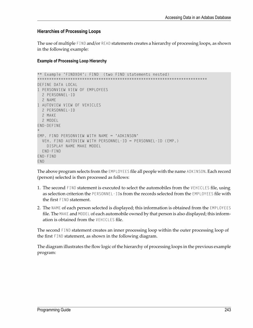
Hierarchies of Processing Loops
The use ofmultiple FIND and/or READ statements creates a hierarchy of processing loops, as shownin the following example:
Example of Processing Loop Hierarchy
** Example 'FINDX04': FIND (two FIND statements nested)************************************************************************DEFINE DATA LOCAL1 PERSONVIEW VIEW OF EMPLOYEES
2 PERSONNEL-ID2 NAME
1 AUTOVIEW VIEW OF VEHICLES2 PERSONNEL-ID2 MAKE2 MODEL
END-DEFINE*EMP. FIND PERSONVIEW WITH NAME = 'ADKINSON'
VEH. FIND AUTOVIEW WITH PERSONNEL-ID = PERSONNEL-ID (EMP.)DISPLAY NAME MAKE MODEL
END-FINDEND-FINDEND
The above program selects from the EMPLOYEES file all peoplewith the name ADKINSON. Each record(person) selected is then processed as follows:
1. The second FIND statement is executed to select the automobiles from the VEHICLES file, usingas selection criterion the PERSONNEL-IDs from the records selected from the EMPLOYEES file withthe first FIND statement.
2. The NAME of each person selected is displayed; this information is obtained from the EMPLOYEESfile. The MAKE and MODEL of each automobile owned by that person is also displayed; this inform-ation is obtained from the VEHICLES file.
The second FIND statement creates an inner processing loop within the outer processing loop ofthe first FIND statement, as shown in the following diagram.
The diagram illustrates the flow logic of the hierarchy of processing loops in the previous exampleprogram:
243Programming Guide
Accessing Data in an Adabas Database

Programming Guide244
Accessing Data in an Adabas Database

Example of Nested FIND Loops Accessing the Same File
It is also possible to construct a processing loop hierarchy in which the same file is used at bothlevels of the hierarchy:
** Example 'FINDX05': FIND (two FIND statements on same file nested)************************************************************************DEFINE DATA LOCAL1 PERSONVIEW VIEW OF EMPLOYEES
2 NAME2 FIRST-NAME2 CITY
1 #NAME (A40)END-DEFINE*WRITE TITLE LEFT JUSTIFIED
'PEOPLE IN SAME CITY AS:' #NAME / 'CITY:' CITY SKIP 1*FIND PERSONVIEW WITH NAME = 'JONES'
WHERE FIRST-NAME = 'LAUREL'COMPRESS NAME FIRST-NAME INTO #NAME/*FIND PERSONVIEW WITH CITY = CITY
DISPLAY NAME FIRST-NAME CITYEND-FIND
END-FINDEND
The above program first selects all people with name JONES and first name LAUREL from theEMPLOYEES file. Then all who live in the same city are selected from the EMPLOYEES file and a listof these people is created. All field values displayed by the DISPLAY statement are taken from thesecond FIND statement.
Output of Program FINDX05:
PEOPLE IN SAME CITY AS: JONES LAURELCITY: BALTIMORE
NAME FIRST-NAME CITY-------------------- -------------------- --------------------
JENSON MARTHA BALTIMORELAWLER EDDIE BALTIMOREFORREST CLARA BALTIMOREALEXANDER GIL BALTIMORENEEDHAM SUNNY BALTIMOREZINN CARLOS BALTIMOREJONES LAUREL BALTIMORE
245Programming Guide
Accessing Data in an Adabas Database

Further Examples of Nested READ and FIND Statements
See the following example programs:
■ READX04 - READ statement (in combination with FIND and the system variables *NUMBERand *COUNTER)
■ LIMITX01 - LIMIT statement (for READ, FIND loop processing)
Database Update - Transaction Processing
This section describes howNatural performs database updating operations based on transactions.
The following topics are covered:
■ Logical Transaction■ Record Hold Logic■ Backing Out a Transaction■ Restarting a Transaction■ Example of Using Transaction Data to Restart a Transaction
Logical Transaction
Natural performs database updating operations based on transactions, which means that alldatabase update requests are processed in logical transaction units. A logical transaction is thesmallest unit of work (as defined by you) which must be performed in its entirety to ensure thatthe information contained in the database is logically consistent.
A logical transaction may consist of one or more update statements (DELETE, STORE, UPDATE) in-volving one ormore database files. A logical transactionmay also spanmultipleNatural programs.
A logical transaction beginswhen a record is put on “hold”; Natural does this automaticallywhenthe record is read for updating, for example, if a FIND loop contains an UPDATE or DELETE statement.
The end of a logical transaction is determined by an END TRANSACTION statement in the program.This statement ensures that all updates within the transaction have been successfully applied, andreleases all records that were put on “hold” during the transaction.
Programming Guide246
Accessing Data in an Adabas Database

Example:
DEFINE DATA LOCAL1 MYVIEW VIEW OF EMPLOYEES
2 NAMEEND-DEFINEFIND MYVIEW WITH NAME = 'SMITH'
DELETEEND TRANSACTION
END-FINDEND
Each record selected would be put on “hold”, deleted, and then - when the END TRANSACTIONstatement is executed - released from “hold”.
Note: TheNatural profile parameter ETEOP, as set by theNatural administrator, determineswhether or not Natural will generate an END TRANSACTION statement at the end of eachNatural program. Ask your Natural administrator for details.
Example of STORE Statement:
The following example program adds new records to the EMPLOYEES file.
** Example 'STOREX01': STORE (Add new records to EMPLOYEES file)*** CAUTION: Executing this example will modify the database records!************************************************************************DEFINE DATA LOCAL1 EMPLOYEE-VIEW VIEW OF EMPLOYEES
2 PERSONNEL-ID(A8)2 NAME (A20)2 FIRST-NAME (A20)2 MIDDLE-I (A1)2 SALARY (P9/2)2 MAR-STAT (A1)2 BIRTH (D)2 CITY (A20)2 COUNTRY (A3)
*1 #PERSONNEL-ID (A8)1 #NAME (A20)1 #FIRST-NAME (A20)1 #INITIAL (A1)1 #MAR-STAT (A1)1 #SALARY (N9)1 #BIRTH (A8)1 #CITY (A20)1 #COUNTRY (A3)1 #CONF (A1) INIT <'Y'>END-DEFINE
247Programming Guide
Accessing Data in an Adabas Database

*REPEAT
INPUT 'ENTER A PERSONNEL ID AND NAME (OR ''END'' TO END)' //'PERSONNEL-ID : ' #PERSONNEL-ID //'NAME : ' #NAME /'FIRST-NAME : ' #FIRST-NAME
/*********************************************************************/* validate entered data/*********************************************************************IF #PERSONNEL-ID = 'END' OR #NAME = 'END'
STOPEND-IFIF #NAME = ' '
REINPUT WITH TEXT 'ENTER A LAST-NAME'MARK 2 AND SOUND ALARM
END-IFIF #FIRST-NAME = ' '
REINPUT WITH TEXT 'ENTER A FIRST-NAME'MARK 3 AND SOUND ALARM
END-IF/*********************************************************************/* ensure person is not already on file/*********************************************************************FIP2. FIND NUMBER EMPLOYEE-VIEW WITH PERSONNEL-ID = #PERSONNEL-ID/*IF *NUMBER (FIP2.) > 0
REINPUT 'PERSON WITH SAME PERSONNEL-ID ALREADY EXISTS'MARK 1 AND SOUND ALARM
END-IF/*********************************************************************/* get further information/*********************************************************************INPUT
'ENTER EMPLOYEE DATA' ////'PERSONNEL-ID :' #PERSONNEL-ID (AD=IO) /'NAME :' #NAME (AD=IO) /'FIRST-NAME :' #FIRST-NAME (AD=IO) ///'INITIAL :' #INITIAL /'ANNUAL SALARY :' #SALARY /'MARITAL STATUS :' #MAR-STAT /'DATE OF BIRTH (YYYYMMDD) :' #BIRTH /'CITY :' #CITY /'COUNTRY (3 CHARS) :' #COUNTRY //'ADD THIS RECORD (Y/N) :' #CONF (AD=M)
/*********************************************************************/* ENSURE REQUIRED FIELDS CONTAIN VALID DATA/*********************************************************************IF #SALARY < 10000
REINPUT TEXT 'ENTER A PROPER ANNUAL SALARY' MARK 2END-IFIF NOT (#MAR-STAT = 'S' OR = 'M' OR = 'D' OR = 'W')
REINPUT TEXT 'ENTER VALID MARITAL STATUS S=SINGLE ' -
Programming Guide248
Accessing Data in an Adabas Database

'M=MARRIED D=DIVORCED W=WIDOWED' MARK 3END-IFIF NOT(#BIRTH = MASK(YYYYMMDD) AND #BIRTH = MASK(1582-2699))
REINPUT TEXT 'ENTER CORRECT DATE' MARK 4END-IFIF #CITY = ' '
REINPUT TEXT 'ENTER A CITY NAME' MARK 5END-IFIF #COUNTRY = ' '
REINPUT TEXT 'ENTER A COUNTRY CODE' MARK 6END-IFIF NOT (#CONF = 'N' OR= 'Y')
REINPUT TEXT 'ENTER Y (YES) OR N (NO)' MARK 7END-IFIF #CONF = 'N'
ESCAPE TOPEND-IF/*********************************************************************/* add the record with STORE/*********************************************************************MOVE #PERSONNEL-ID TO EMPLOYEE-VIEW.PERSONNEL-IDMOVE #NAME TO EMPLOYEE-VIEW.NAMEMOVE #FIRST-NAME TO EMPLOYEE-VIEW.FIRST-NAMEMOVE #INITIAL TO EMPLOYEE-VIEW.MIDDLE-IMOVE #SALARY TO EMPLOYEE-VIEW.SALARY (1)MOVE #MAR-STAT TO EMPLOYEE-VIEW.MAR-STATMOVE EDITED #BIRTH TO EMPLOYEE-VIEW.BIRTH (EM=YYYYMMDD)MOVE #CITY TO EMPLOYEE-VIEW.CITYMOVE #COUNTRY TO EMPLOYEE-VIEW.COUNTRY/*STP3. STORE RECORD IN FILE EMPLOYEE-VIEW/*/*********************************************************************/* mark end of logical transaction/*********************************************************************END OF TRANSACTIONRESET INITIAL #CONF
END-REPEATEND
Output of Program STOREX01:
ENTER A PERSONNEL ID AND NAME (OR 'END' TO END)
PERSONNEL ID :
NAME :FIRST NAME :
249Programming Guide
Accessing Data in an Adabas Database

Record Hold Logic
If Natural is used with Adabas, any record which is to be updated will be placed in “hold” statusuntil an END TRANSACTION or BACKOUT TRANSACTION statement is issued or the transaction timelimit is exceeded.
When a record is placed in “hold” status for one user, the record is not available for update byanother user. Another user who wishes to update the same record will be placed in “wait” statusuntil the record is released from “hold” when the first user ends or backs out his/her transaction.
To prevent users from being placed in wait status, the session parameter WH (Wait for Record inHold Status) can be used (see the Parameter Reference).
When you use update logic in a program, you should consider the following:
■ The maximum time that a record can be in hold status is determined by the Adabas transactiontime limit (Adabas parameter TT). If this time limit is exceeded, youwill receive an errormessageand all database modifications done since the last END TRANSACTIONwill be made undone.
■ The number of records on hold and the transaction time limit are affected by the size of atransaction, that is, by the placement of the END TRANSACTION statement in the program. Restartfacilities should be consideredwhen decidingwhere to issue an END TRANSACTION. For example,if a majority of records being processed are not to be updated, the GET statement is an efficientway of controlling the “holding” of records. This avoids issuing multiple END TRANSACTIONstatements and reduces the number of ISNs on hold. When you process large files, you shouldbear in mind that the GET statement requires an additional Adabas call. An example of a GETstatement is shown below.
Example of Hold Logic:
** Example 'GETX01': GET (put single record in hold with UPDATE stmt)**** CAUTION: Executing this example will modify the database records!***********************************************************************DEFINE DATA LOCAL1 EMPLOY-VIEW VIEW OF EMPLOYEES
2 NAME2 SALARY (1)
END-DEFINE*RD. READ EMPLOY-VIEW BY NAME
DISPLAY EMPLOY-VIEWIF SALARY (1) > 1500000
/*GE. GET EMPLOY-VIEW *ISN (RD.)/*WRITE '=' (50) 'RECORD IN HOLD:' *ISN(RD.)COMPUTE SALARY (1) = SALARY (1) * 1.15UPDATE (GE.)
Programming Guide250
Accessing Data in an Adabas Database

END TRANSACTIONEND-IF
END-READEND
Backing Out a Transaction
During an active logical transaction, that is, before the END TRANSACTION statement is issued, youcan cancel the transaction by using a BACKOUT TRANSACTION statement. The execution of thisstatement removes all updates that have been applied (including all records that have been addedor deleted) and releases all records held by the transaction.
Restarting a Transaction
With the END TRANSACTION statement, you can also store transaction-related information. If pro-cessing of the transaction terminates abnormally, you can read this information with a GETTRANSACTION DATA statement to ascertain where to resume processing when you restart thetransaction.
Example of Using Transaction Data to Restart a Transaction
The following program updates the EMPLOYEES and VEHICLES files. After a restart operation, theuser is informedof the last EMPLOYEES record successfully processed. The user can resumeprocessingfrom that EMPLOYEES record. It would also be possible to set up the restart transaction message toinclude the last VEHICLES record successfully updated before the restart operation.
** Example 'GETTRX01': GET TRANSACTION*** CAUTION: Executing this example will modify the database records!************************************************************************DEFINE DATA LOCAL01 PERSON VIEW OF EMPLOYEES
02 PERSONNEL-ID (A8)02 NAME (A20)02 FIRST-NAME (A20)02 MIDDLE-I (A1)02 CITY (A20)
01 AUTO VIEW OF VEHICLES02 PERSONNEL-ID (A8)02 MAKE (A20)02 MODEL (A20)
*01 ET-DATA
02 #APPL-ID (A8) INIT <' '>02 #USER-ID (A8)02 #PROGRAM (A8)02 #DATE (A10)02 #TIME (A8)
251Programming Guide
Accessing Data in an Adabas Database
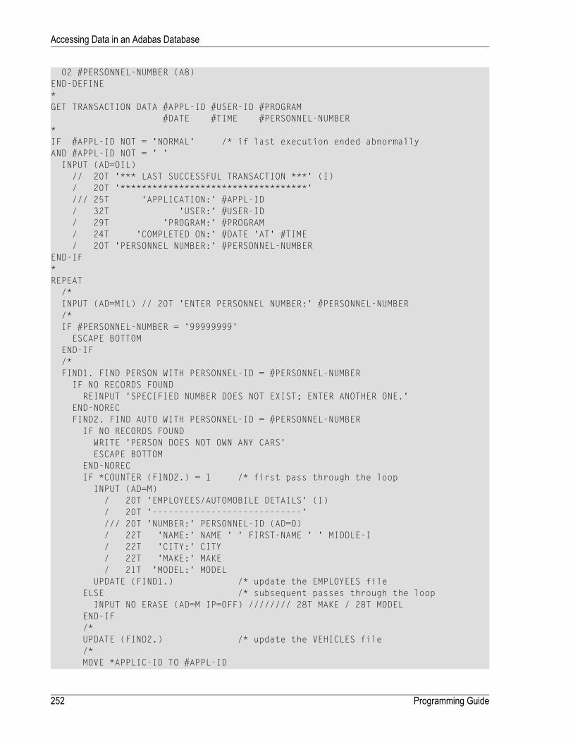
02 #PERSONNEL-NUMBER (A8)END-DEFINE*GET TRANSACTION DATA #APPL-ID #USER-ID #PROGRAM
#DATE #TIME #PERSONNEL-NUMBER*IF #APPL-ID NOT = 'NORMAL' /* if last execution ended abnormallyAND #APPL-ID NOT = ' '
INPUT (AD=OIL)// 20T '*** LAST SUCCESSFUL TRANSACTION ***' (I)/ 20T '***********************************'/// 25T 'APPLICATION:' #APPL-ID/ 32T 'USER:' #USER-ID/ 29T 'PROGRAM:' #PROGRAM/ 24T 'COMPLETED ON:' #DATE 'AT' #TIME/ 20T 'PERSONNEL NUMBER:' #PERSONNEL-NUMBER
END-IF*REPEAT
/*INPUT (AD=MIL) // 20T 'ENTER PERSONNEL NUMBER:' #PERSONNEL-NUMBER/*IF #PERSONNEL-NUMBER = '99999999'
ESCAPE BOTTOMEND-IF/*FIND1. FIND PERSON WITH PERSONNEL-ID = #PERSONNEL-NUMBER
IF NO RECORDS FOUNDREINPUT 'SPECIFIED NUMBER DOES NOT EXIST; ENTER ANOTHER ONE.'
END-NORECFIND2. FIND AUTO WITH PERSONNEL-ID = #PERSONNEL-NUMBERIF NO RECORDS FOUND
WRITE 'PERSON DOES NOT OWN ANY CARS'ESCAPE BOTTOM
END-NORECIF *COUNTER (FIND2.) = 1 /* first pass through the loop
INPUT (AD=M)/ 20T 'EMPLOYEES/AUTOMOBILE DETAILS' (I)/ 20T '----------------------------'/// 20T 'NUMBER:' PERSONNEL-ID (AD=O)/ 22T 'NAME:' NAME ' ' FIRST-NAME ' ' MIDDLE-I/ 22T 'CITY:' CITY/ 22T 'MAKE:' MAKE/ 21T 'MODEL:' MODEL
UPDATE (FIND1.) /* update the EMPLOYEES fileELSE /* subsequent passes through the loop
INPUT NO ERASE (AD=M IP=OFF) //////// 28T MAKE / 28T MODELEND-IF/*UPDATE (FIND2.) /* update the VEHICLES file/*MOVE *APPLIC-ID TO #APPL-ID
Programming Guide252
Accessing Data in an Adabas Database

MOVE *INIT-USER TO #USER-IDMOVE *PROGRAM TO #PROGRAMMOVE *DAT4E TO #DATEMOVE *TIME TO #TIME/*END TRANSACTION #APPL-ID #USER-ID #PROGRAM
#DATE #TIME #PERSONNEL-NUMBER/*
END-FIND /* for VEHICLES (FIND2.)END-FIND /* for EMPLOYEES (FIND1.)
END-REPEAT /* for REPEAT*STOP /* Simulate abnormal transaction endEND TRANSACTION 'NORMAL 'END
Selecting Records Using ACCEPT/REJECT
This section discusses the statements ACCEPT and REJECTwhich are used to select records basedon user-specified logical criteria.
The following topics are covered:
■ Statements Usable with ACCEPT and REJECT■ Example of ACCEPT Statement■ Logical Condition Criteria in ACCEPT/REJECT Statements■ Example of ACCEPT Statement with AND Operator■ Example of REJECT Statement with OR Operator■ Further Examples of ACCEPT and REJECT Statements
Statements Usable with ACCEPT and REJECT
The statements ACCEPT and REJECT can be used in conjunctionwith the database access statements:
■ READ
■ FIND
■ HISTOGRAM
253Programming Guide
Accessing Data in an Adabas Database

Example of ACCEPT Statement
** Example 'ACCEPX01': ACCEPT IF************************************************************************DEFINE DATA LOCAL1 MYVIEW VIEW OF EMPLOYEES
2 NAME2 JOB-TITLE2 CURR-CODE (1:1)2 SALARY (1:1)
END-DEFINE*READ (20) MYVIEW BY NAME WHERE CURR-CODE (1) = 'USD'ACCEPT IF SALARY (1) >= 40000
DISPLAY NAME JOB-TITLE SALARY (1)END-READEND
Output of Program ACCEPX01:
Page 1 04-11-11 11:11:11 NAME CURRENT ANNUAL POSITION SALARY -------------------- ------------------------- ---------- ADKINSON DBA 46700 ADKINSON MANAGER 47000 ADKINSON MANAGER 47000 AFANASSIEV DBA 42800 ALEXANDER DIRECTOR 48000 ANDERSON MANAGER 50000 ATHERTON ANALYST 43000 ATHERTON MANAGER 40000 ↩
Logical Condition Criteria in ACCEPT/REJECT Statements
The statements ACCEPT and REJECT allow you to specify logical conditions in addition to those thatwere specified in WITH and WHERE clauses of the READ statement.
The logical condition criteria in the IF clause of an ACCEPT / REJECT statement are evaluated afterthe record has been selected and read.
Logical condition operators include the following (seeLogical Condition Criteria formore detailedinformation):
Programming Guide254
Accessing Data in an Adabas Database

:=EQEQUAL
¬=NENOT EQUAL TO
<LTLESS THAN
<=LELESS EQUAL
>GTGREATER THAN
>=GEGREATER EQUAL
Logical condition criteria in ACCEPT / REJECT statements may also be connected with the Booleanoperators AND, OR, and NOT. Moreover, parentheses may be used to indicate logical grouping; seethe following examples.
Example of ACCEPT Statement with AND Operator
The following program illustrates the use of the Boolean operator AND in an ACCEPT statement.
** Example 'ACCEPX02': ACCEPT IF ... AND ...************************************************************************DEFINE DATA LOCAL1 MYVIEW VIEW OF EMPLOYEES
2 NAME2 JOB-TITLE2 CURR-CODE (1:1)2 SALARY (1:1)
END-DEFINE*READ (20) MYVIEW BY NAME WHERE CURR-CODE (1) = 'USD'ACCEPT IF SALARY (1) >= 40000
AND SALARY (1) <= 45000DISPLAY NAME JOB-TITLE SALARY (1)
END-READEND
Output of Program ACCEPX02:
Page 1 04-12-14 12:22:01 NAME CURRENT ANNUAL POSITION SALARY -------------------- ------------------------- ---------- AFANASSIEV DBA 42800 ATHERTON ANALYST 43000 ATHERTON MANAGER 40000 ↩
255Programming Guide
Accessing Data in an Adabas Database

Example of REJECT Statement with OR Operator
The following program, which uses the Boolean operator OR in a REJECT statement, produces thesame output as the ACCEPT statement in the example above, as the logical operators are reversed.
** Example 'ACCEPX03': REJECT IF ... OR ...************************************************************************DEFINE DATA LOCAL1 MYVIEW VIEW OF EMPLOYEES
2 NAME2 JOB-TITLE2 CURR-CODE (1:1)2 SALARY (1:1)
END-DEFINE*READ (20) MYVIEW BY NAME WHERE CURR-CODE (1) = 'USD'REJECT IF SALARY (1) < 40000
OR SALARY (1) > 45000DISPLAY NAME JOB-TITLE SALARY (1)
END-READEND
Output of Program ACCEPX03:
Page 1 04-12-14 12:26:27 NAME CURRENT ANNUAL POSITION SALARY -------------------- ------------------------- ---------- AFANASSIEV DBA 42800 ATHERTON ANALYST 43000 ATHERTON MANAGER 40000 ↩
Further Examples of ACCEPT and REJECT Statements
See the following example programs:
■ ACCEPX04 - ACCEPT IF ... LESS THAN ...■ ACCEPX05 - ACCEPT IF ... AND ...■ ACCEPX06 - REJECT IF ... OR ...
Programming Guide256
Accessing Data in an Adabas Database

AT START/END OF DATA Statements
This section discusses the use of the statements AT START OF DATA and AT END OF DATA.
The following topics are covered:
■ AT START OF DATA Statement■ AT END OF DATA Statement■ Example of AT START OF DATA and AT END OF DATA Statements■ Further Examples of AT START OF DATA and AT END OF DATA
AT START OF DATA Statement
The AT START OF DATA statement is used to specify any processing that is to be performed afterthe first of a set of records has been read in a database processing loop.
The AT START OF DATA statement must be placed within the processing loop.
If the AT START OF DATA processing produces any output, this will be output before the first fieldvalue. By default, this output is displayed left-justified on the page.
AT END OF DATA Statement
The AT END OF DATA statement is used to specify processing that is to be performed after all recordsfor a database processing loop have been processed.
The AT END OF DATA statement must be placed within the processing loop.
If the AT END OF DATA processing produces any output, this will be output after the last field value.By default, this output is displayed left-justified on the page.
Example of AT START OF DATA and AT END OF DATA Statements
The following example program illustrates the use of the statements AT START OF DATA and ATEND OF DATA.
The Natural system variable *TIME has been incorporated into the AT START OF DATA statementto display the time of day.
The Natural system function OLD has been incorporated into the AT END OF DATA statement todisplay the name of the last person selected.
257Programming Guide
Accessing Data in an Adabas Database

** Example 'ATSTAX01': AT START OF DATA************************************************************************DEFINE DATA LOCAL1 MYVIEW VIEW OF EMPLOYEES
2 CITY2 NAME2 JOB-TITLE2 INCOME (1:1)
3 CURR-CODE3 SALARY3 BONUS (1:1)
END-DEFINE*WRITE TITLE 'XYZ EMPLOYEE ANNUAL SALARY AND BONUS REPORT' /READ (3) MYVIEW BY CITY STARTING FROM 'E'
DISPLAY GIVE SYSTEM FUNCTIONSNAME (AL=15) JOB-TITLE (AL=15) INCOME (1)
/*AT START OF DATA
WRITE 'RUN TIME:' *TIME /END-STARTAT END OF DATA
WRITE / 'LAST PERSON SELECTED:' OLD (NAME) /END-ENDDATA
END-READ*AT END OF PAGE
WRITE / 'AVERAGE SALARY:' AVER (SALARY(1))END-ENDPAGEEND
The program produces the following output:
XYZ EMPLOYEE ANNUAL SALARY AND BONUS REPORT NAME CURRENT INCOME POSITION CURRENCY ANNUAL BONUS CODE SALARY --------------- --------------- -------- ---------- ---------- RUN TIME: 12:43:19.1 DUYVERMAN PROGRAMMER USD 34000 0PRATT SALES PERSON USD 38000 9000MARKUSH TRAINEE USD 22000 0 LAST PERSON SELECTED: MARKUSH AVERAGE SALARY: 31333 ↩
Programming Guide258
Accessing Data in an Adabas Database

Further Examples of AT START OF DATA and AT END OF DATA
See the following example programs:
■ ATENDX01 - AT END OF DATA■ ATSTAX02 - AT START OF DATA■ WRITEX09 - WRITE (in combination with AT END OF DATA )
Unicode Data
Natural enables users to access wide-character fields (format W) in an Adabas database.
The following topics are covered:
■ Data Definition Module■ Access Configuration■ Restrictions
Data Definition Module
Adabas wide-character fields (W) are mapped to Natural format U (Unicode).
The length definition for a Natural field of format U corresponds to half the size of the Adabasfield of formatW. AnAdabaswide-character field of length 200 is, for example, mapped to (U100)in Natural.
Access Configuration
Natural receives data fromAdabas and sends data to Adabas using UTF-16 as common encoding.
This encoding is specified with the OPRB parameter and sent to Adabas with the open request. Itis used for wide-character fields and applies to the entire Adabas user session.
Restrictions
Wide-character fields (W) of variable length are not supported.
Collating descriptors are not supported.
For further information on Adabas and Unicode support refer to the specific Adabas productdocumentation.
259Programming Guide
Accessing Data in an Adabas Database

260

26 Accessing Data in an SQL Database
■ Generating Natural DDMs ............................................................................................................... 262■ Setting Natural Profile Parameters .................................................................................................... 262■ Natural DML Statements ................................................................................................................. 263■ Natural SQL Statements ................................................................................................................. 269■ Flexible SQL ................................................................................................................................. 277■ RDBMS-Specific Requirements and Restrictions .................................................................................. 278■ Data-Type Conversion .................................................................................................................... 281■ Date/Time Conversion .................................................................................................................... 281■ Obtaining Diagnostic Information about Database Errors ....................................................................... 283■ SQL Authorization .......................................................................................................................... 283
261

This chapter describes how to use Natural with SQL databases via Entire Access. For informationabout installation and configuration, see Natural and Entire Access in the Database ManagementSystem Interfaces documentation and the separate Entire Access documentation.
Note: On principle, the features and examples contained in the document Accessing Datain an Adabas Database also apply to the SQL databases supported byNatural. Differences,if any, are described in the documents for the individual database access statements (seethe Statements documentation) in paragraphs named Database-Specific Considerations or inthe documents for the individual Natural parameters (see the Parameter Reference). In addi-tion, Natural offers a specific set of statements to access SQL databasess.
Generating Natural DDMs
Entire Access is an application programming interface (API) that supportsNatural SQL statementsand most Natural DML statements.
Natural DML and SQL statements can be used in the same Natural program. At compilation, if aDML statement references a DDM for a data source defined in NATCONF.CFGwith DBMS typeSQL, Natural translates the DML statement into an SQL statement.
Natural converts DML and SQL statements into calls to Entire Access. Entire Access converts therequests to the data formats and SQLdialect required by the target RDBMS and passes the requeststo the database driver.
Setting Natural Profile Parameters
ETEOP Parameter
This parameter can be set only by Natural administrators.
The Natural profile parameter ETEOP controls transaction processing during a Natural session. Itis required, for example, if a single logical transaction is to span two or more Natural programs.In this case, Natural must not issue an END TRANSACTION command (that is, not “commit”) at thetermination of a Natural program.
If the ETEOP parameter is set to:
Programming Guide262
Accessing Data in an SQL Database

Natural issues an END TRANSACTION statement (that is, automatically “commits”) at the end of aNatural program if the Natural session is not at ET status.
ON
Natural does not issue an END TRANSACTION command (that is, does not “commit”) at the end of aNatural program. This setting thus enables a single logical transaction to span more than one Naturalprogram.
OFF
This is the default.
Note: The ETEOP parameter applies to Natural Version 6.1 and above. With previous Nat-ural versions, the Natural profile parameter OPRB has to be used instead of ETEOP (ETEOP=ONcorresponds to OPRB=OFF, ETEOP=OFF corresponds to ORPB=NOOPEN).
Natural DML Statements
The following table shows how Natural translates DML statements into SQL statements:
SQL StatementDML Statement
ROLLBACKBACKOUT TRANSACTION
DELETE WHERE CURRENT OF cursor-nameDELETE
COMMITEND TRANSACTION
IN (...)EQUAL ... OR
BETWEEN ... AND ...EQUAL ... THRU ...
SELECTFIND ALL
SELECT COUNT (*)FIND NUMBER
SELECT COUNT (*)HISTOGRAM
SELECT ... ORDER BYREAD LOGICAL
SELECT ... ORDER BYREAD PHYSICAL
ORDER BY ... [DESCENDING]SORTED BY ... [DESCENDING]
INSERTSTORE
UPDATE WHERE CURRENT of cursor-nameUPDATE
WHEREWITH
Note: Boolean and relational operators function the sameway inDML and SQL statements.
Entire Access does not support the following DML statements and options:
■ CIPHER
■ COUPLED
■ FIND FIRST, FIND UNIQUE, FIND ... RETAIN AS
263Programming Guide
Accessing Data in an SQL Database

■ GET, GET SAME, GET TRANSACTION DATA, GET RECORD
■ PASSWORD
■ READ BY ISN
■ STORE USING/GIVING NUMBER
BACKOUT TRANSACTION
Natural translates a BACKOUT TRANSACTION statement into an SQL ROLLBACK command. Thisstatement reverses all database modifications made after the completion of the last recovery unit.A recovery unit may start at the beginning of a session or after the last END TRANSACTION (COMMIT)or BACKOUT TRANSACTION (ROLLBACK) statement.
Note: Because all cursors are closedwhen a logical unit of work ends, do not place a BACKOUTTRANSACTION statementwithin a database loop; place it outside the loop or after the outermostloop of nested loops.
DELETE
The DELETE statement deletes a row from a database table that has been read with a precedingFIND, READ, or SELECT statement. It corresponds to the SQL statement DELETE WHERE CURRENT OFcursor-name, which means that only the last row that was read can be deleted.
Example:
FIND EMPLOYEES WITH NAME = 'SMITH'AND FIRST_NAME = 'ROGER'
DELETE
Natural translates the Natural statements above into the following SQL statements and assigns acursor name (for example, CURSOR1). The SELECT statement and the DELETE statement refer to thesame cursor.
SELECT FROM EMPLOYEESWHERE NAME = 'SMITH' AND FIRST_NAME = 'ROGER'
DELETE FROM EMPLOYEESWHERE CURRENT OF CURSOR1
Natural translates a DELETE statement into an SQL DELETE statement the way it translates a FINDstatement into an SQL SELECT statement. For details, see the FIND statement description below.
Note: You cannot delete a row read with a FIND SORTED BY or READ LOGICAL statement.For an explanation, see the FIND and READ statement descriptions below.
Programming Guide264
Accessing Data in an SQL Database

END TRANSACTION
Natural translates an END TRANSACTION statement into an SQL COMMIT command. The ENDTRANSACTION statement indicates the end of a logical transaction, commits all modifications to thedatabase, and releases data locked during the transaction.
Notes:
1. Because all cursors are closedwhen a logical unit ofwork ends, do not place an END TRANSACTIONstatement within a database loop; place it outside the loop or after the outermost loop of nestedloops.
2. The END TRANSACTION statement cannot be used to store transaction (ET) data when used withEntire Access.
3. Entire Access does not issue a COMMIT automatically when the Natural program terminates.
FIND
Natural translates a FIND statement into an SQL SELECT statement. The SELECT statement is executedby an OPEN CURSOR command followed by a FETCH command. The FETCH command is executedrepeatedly until all records have been read or the program exits the FIND processing loop. A CLOSECURSOR command ends the SELECT processing.
Example:
Natural statements:
FIND EMPLOYEES WITH NAME = 'BLACKMORE'AND AGE EQ 20 THRU 40
OBTAIN PERSONNEL_ID NAME AGE
Equivalent SQL statement:
SELECT PERSONNEL_ID, NAME, AGEFROM EMPLOYEES
WHERE NAME = 'BLACKMORE'AND AGE BETWEEN 20 AND 40
You can use any table column (field) designated as a descriptor to construct search criteria.
Natural translates the WITH clause of a FIND statement into the WHERE clause of an SQL SELECTstatement. Natural evaluates the WHERE clause of the FIND statement after the rows have been se-lected using the WITH clause. View fields may be used in a WITH clause only if they are designatedas descriptors.
265Programming Guide
Accessing Data in an SQL Database

Natural translates a FIND NUMBER statement into an SQL SELECT statement containing a COUNT(*)clause. When you want to determine whether a record exists for a specific search condition, theFIND NUMBER statement provides better performance than the IF NO RECORDS FOUND clause.
Note: A row read with a FIND statement containing a SORTED BY clause cannot be updatedor deleted. Natural translates the SORTED BY clause of a FIND statement into the ORDER BYclause of an SQL SELECT statement, which produces a read-only result table.
HISTOGRAM
Natural translates the HISTOGRAM statement into an SQL SELECT statement. The HISTOGRAM statementreturns the number of rows in a table that have the same value in a specific column. The numberof rows is returned in the Natural system variable *NUMBER.
Example:
Natural statements:
HISTOGRAM EMPLOYEES FOR AGEOBTAIN AGE
Equivalent SQL statements:
SELECT AGE, COUNT(*) FROM EMPLOYEESGROUP BY AGEORDER BY AGE
READ
Natural translates a READ statement into an SQL SELECT statement. Both READ PHYSICAL and READLOGICAL statements can be used.
A row read with a READ LOGICAL statement (Example 1) cannot be updated or deleted. Naturaltranslates a READ LOGICAL statement into the ORDER BY clause of an SQL SELECT statement, whichproduces a read-only result table.
A READ PHYSICAL statement (Example 2) can be updated or deleted. Natural translates it into aSELECT statement without an ORDER BY clause.
Example 1:
Natural statements:
Programming Guide266
Accessing Data in an SQL Database

READ PERSONNEL BY NAMEOBTAIN NAME FIRSTNAME DATEOFBIRTH
Equivalent SQL statement:
SELECT NAME, FIRSTNAME, DATEOFBIRTH FROM PERSONNELWHERE NAME >= ' '
ORDER BY NAME
Example 2:
Natural statements:
READ PERSONNEL PHYSICALOBTAIN NAME
Equivalent SQL statement:
SELECT NAME FROM PERSONNEL
When a READ statement contains a WHERE clause, Natural evaluates the WHERE clause after the rowshave been selected according to the search criterion.
STORE
The STORE statement adds a row to a database table. It corresponds to the SQL INSERT statement.
Example:
Natural statement:
STORE RECORD IN EMPLOYEESWITH PERSONNEL_ID = '2112'
NAME = 'LIFESON'FIRST_NAME = 'ALEX'
Equivalent SQL statement:
INSERT INTO EMPLOYEES (PERSONNEL_ID, NAME, FIRST_NAME)VALUES ('2112', 'LIFESON', 'ALEX')
267Programming Guide
Accessing Data in an SQL Database

UPDATE
The DML UPDATE statement updates a table row that has been read with a preceding FIND, READ,or SELECT statement. Natural translates the DML UPDATE statement into the SQL statement UPDATEWHERE CURRENT OF cursor-name (a positioned UPDATE statement), which means that only the lastrow that was read can be updated. In the case of nested loops, the last row in each nested loopcan be updated.
UPDATE with FIND/READ
When a DML UPDATE statement is used after a Natural FIND statement, Natural translates the FINDstatement into an SQL SELECT statement with a FOR UPDATE OF clause, and translates the DMLUPDATE statement into an UPDATE WHERE CURRENT OF cursor-name statement.
Example:
FIND EMPLOYEES WITH SALARY < 5000ASSIGN SALARY = 6000UPDATE
Natural translates the Natural statements above into the following SQL statements and assigns acursor name (for example, CURSOR1). The SELECT and UPDATE statements refer to the same cursor.
SELECT SALARY FROM EMPLOYEES WHERE SALARY < 5000FOR UPDATE OF SALARY
UPDATE EMPLOYEES SET SALARY = 6000WHERE CURRENT OF CURSOR1
You cannot update a row read with a FIND SORTED BY or READ LOGICAL statement. For an explan-ation, see the FIND and READ statement descriptions above.
An END TRANSACTION or BACKOUT TRANSACTION statement releases data locked by an UPDATEstatement.
UPDATE with SELECT
The DML UPDATE statement can be used after a SELECT statement only in the following case:
SELECT *INTO VIEW view-name
Natural rejects any other form of the SELECT statement used with the DML UPDATE statement.Natural translates theDML UPDATE statement into a non-cursor or “searched” SQL UPDATE statement,which means than only an entire Natural view can be updated; individual columns cannot beupdated.
Programming Guide268
Accessing Data in an SQL Database

In addition, the DML UPDATE statement can be used after a SELECT statement only in Naturalstructured mode, which has the following syntax:
UPDATE [RECORD] [IN] [STATEMENT] [(r)]
Example:
DEFINE DATA LOCAL01 PERS VIEW OF SQL-PERSONNEL
02 NAME02 AGE
END-DEFINESELECT *
INTO VIEW PERSFROM SQL-PERSONNELWHERE NAME LIKE 'S%'OBTAIN NAME
IF NAME = 'SMITH'ADD 1 TO AGE
UPDATEEND-IF
END-SELECT
In other respects, the DML UPDATE statement works with the SELECT statement the way it workswith the Natural FIND statement (see UPDATE with FIND/READ above).
Natural SQL Statements
The SQL statements available within the Natural programming language comprise two differentsets of statements: the common set and the extended set. On this platform, only the extended setis supported by Natural.
The common set can be handled by each SQL-eligible database system supported by Natural. Itbasically corresponds to the standard SQL syntax definitions. For a detailed description of thecommon set of Natural SQL statements, see Common Set and Extended Set (in the Statements docu-mentation).
This section describes considerations and restrictions when using the common set of Natural SQLstatements with Entire Access.
■ DELETE■ INSERT■ PROCESS SQL■ SELECT
269Programming Guide
Accessing Data in an SQL Database
■ UPDATE
DELETE
The Natural SQL DELETE statement deletes rows in a table without using a cursor.
Whereas Natural translates the DML DELETE statement into a positioned DELETE statement (thatis, an SQL DELETE WHERE CURRENT OF cursor-name statement), theNatural SQL DELETE statementis a non-cursor or searched DELETE statement. A searched DELETE statement is a stand-alonestatement unrelated to any SELECT statement.
INSERT
The INSERT statement adds rows to a table; it corresponds to the Natural STORE statement.
PROCESS SQL
The PROCESS SQL statement issues SQL statements in a statement-string to the database identifiedby a ddm-name.
Note: It is not possible to run database loops using the PROCESS SQL statement.
Parameters
Natural supports the INDICATOR and LINDICATOR clauses. As an alternative, the statement-stringmay include parameters. The syntax item parameter is syntactically defined as follows:
:host-variable:U
:G
A host-variable is a Natural program variable referenced in an SQL statement.
SET SQLOPTION option=value
With Entire Access, you can also specify SET SQLOPTION option=value as statement-string.This can be used to specify various options for accessing SQL databases. The options apply onlyto the database referenced by the PROCESS SQL statement.
Supported options are:
■ DATEFORMAT
■ DBPROCESS (for Sybase only)■ TIMEOUT (for Sybase only)■ TRANSACTION (for Sybase only)
Programming Guide270
Accessing Data in an SQL Database

DATEFORMAT
This option specifies the format used to retrieve SQL Date and Datetime information into Naturalfields of type A. The option is obsolete if Natural fields of type D or T are used. A subset of theNatural date and time edit masks can be used:
Year (4 digits)YYYY
Year (2 digits)YY
MonthMM
DayDD
HourHH
MinuteII
SecondSS
If the date format contains blanks, it must be enclosed in apostrophes.
Examples:
To use ISO date format, specify
PROCESS SQL sql-ddm << SET SQLOPTION DATEFORMAT = YYYY-MM-DD >>
To obtain date and time components in ISO format, specify
PROCESS SQL sql-ddm << SET SQLOPTION DATEFORMAT = 'YYYY-MM-DD HH:II:SS' >>
The DATEFORMAT is evaluated only if data are retrieved from the database. If data are passed to thedatabase, the conversion is done by the database system. Therefore, the format specified withDATEFORMAT should be a valid date format of the underlying database.
If no DATEFORMAT is specified for Natural fields,
■ the default date format DD-MON-YY is used (where MON is a 3-letter abbreviation of the Englishmonth name) and
■ the following default datetime formats are used:
YYYYMMDDHHIISSAdabas D
YYYY-MM-DD-HH.II.SSDB2
YYYY-MM-DD HH:II:SSINFORMIX
YYYY-MM-DD HH:II:SSODBC
YYYYMMDDHHIISSORACLE
YYYYMMDD HH:II:SSSYBASE DBLIB
YYYYMMDD HH:II:SSSYBASE CTLIB
271Programming Guide
Accessing Data in an SQL Database

YYYYMMDD HH:II:SSMicrosoft SQL Server
DD-MON-YYother
DBPROCESS
This option is valid for Sybase and Microsoft SQL Server databases only.
This option is used to influence the allocation of SQL statements to Sybase and Microsoft SQLServer DBPROCESSes. DBPROCESSes are used by Entire Access to emulate database cursors, whichare not provided by the Sybase and Microsoft SQL Server DBlib interface.
Two values are possible:
With DBPROCESS set to MULTIPLE, each SELECT statement uses its own secondary DBPROCESS,whereas all other SQL statements are executed within the primary DBPROCESS. The value
MULTIPLE
MULTIPLE therefore enables your application to execute further SQL statements, even if adatabase loop is open. It also allows nested database loops.
With DBPROCESS set to SINGLE, all SQL statements use the same (that is, the primary)DBPROCESS. It is therefore not possible to execute a new database statement while a database
SINGLE
loop is active, because one DBPROCESS can only execute one SQL batch at a time. Since allstatements are executed in the same (primary) DBPROCESS, however, this setting enablesSELECTions from non-shared temporary tables.
Notes:
1. The specified value can only be changed if no database loop is active.
2. As the DBPROCESS option only applies to the Sybase and Microsoft SQL Server DBlib interface,your application should use a central CALLNAT statement to change the value (at least for SINGLE),so that you can easily remove these calls once Sybase client libraries are supported. Your applic-ation should also use a central error handling that establishes the default setting (MULTIPLE).
TIMEOUT
This option is valid for Sybase and Microsoft SQL Server databases only.
With Sybase andMicrosoft SQL Server, Entire Access uses a timeout technique to detect database-access deadlocks. The default timeout period is 8 seconds. With this option, you can change theduration of the timeout period (in seconds).
For example, to set the timeout period to 30 seconds, specify
Programming Guide272
Accessing Data in an SQL Database
PROCESS SQL sql-ddm << SET SQLOPTION TIMEOUT = 30 >>
TRANSACTION
This option is valid for Sybase and Microsoft SQL Server databases only.
This option is used to enable or disable transaction mode. It becomes effective after the next ENDTRANSACTION or BACKOUT TRANSACTION statement.
If transaction mode is enabled (this is the default), Natural automatically issues all requiredstatements to begin a transaction.
Examples:
To disable transaction mode, specify
PROCESS SQL sql-ddm << SET SQLOPTION TRANSACTION = NO >>...END TRANSACTION
To enable transaction mode, specify
PROCESS SQL sql-ddm << SET SQLOPTION TRANSACTION = YES >>...END TRANSACTION
SQLDISCONNECT
With Entire Access, you can also specify SQLDISCONNECT as the statement-string. In combinationwith the SQLCONNECT statement (seebelow), this statement can be used to access different databasesby one application within the same session, by simply connecting and disconnecting as required.
A successfully performed SQLDISCONNECT statement clears the information previously providedby the SQLCONNECT statement; that is, it disconnects your application from the currently connectedSQL database determined by the DBID of the DDM used in the PROCESS SQL statement. If noconnection is established, the SQLDISCONNECT statement is ignored. It will fail if a transaction isopen.
Note: If Natural reports an error in the SQLDISCONNECT statement, the connection statusdoes not change. If the database reports an error, the connection status is undefined.
273Programming Guide
Accessing Data in an SQL Database

SQLCONNECT option=value
With Entire Access, you can also specify SQLCONNECT option=value as the statement-string.This statement can be used to establish a connection to an SQL database according to the DBIDspecified in the DDM addressed by the PROCESS SQL statement. The SQLCONNECT statement willfail if the specified connection is already established.
Supported options are:
■ USERID
■ PASSWORD
■ OS_PASSWORD
■ OS_USERID
■ DBMS_PARAMETER
Notes:
1. If the SQLCONNECT statement fails, the connection status does not change.
2. If several options are specified, they must be separated by a comma.
3. The specified value can be either a character literal or a Natural variable of format A.
4. If Natural performs an implicit reconnect, because the connection to the database was lost, thevalues provided by the SQLCONNECT statement are used.
The options are evaluated as described below.
USERID and PASSWORD
Specifying USERID and PASSWORD for the database logon suppresses the default logonwindow andthe evaluation of the environment variables SQL_DATABASE_USER and SQL_DATABASE_PASSWORD.
If only USERID is specified, PASSWORD is assumed to be blank, and vice versa.
If neither USERID nor PASSWORD is specified, default logon processing applies.
Note: With database systems that do not require user ID and password, a blank user IDand password can be specified to suppress the default logon processing.
Programming Guide274
Accessing Data in an SQL Database
OS_USERID and OS_PASSWORD
Specifying OS_PASSWORD and OS_USERID for the operating system logon suppresses the logonwindow and the evaluation of the environment variables SQL_OS_USER and SQL_OS_PASSWORD.
If only OS_USERID is specified, OS_PASSWORD is assumed to be blank, and vice versa.
If neither OS_USERID nor OS_PASSWORD is specified, default logon processing applies.
Note: With operating systems that do not require user ID and password, a blank user IDand password can be specified to suppress the default logon processing.
DBMS_PARAMETER
Specifying DBMS_PARAMETER dynamically overwrites the DBMS assignment in the Natural globalconfiguration file.
Examples:
PROCESS SQL sql-ddm << SQLCONNECT USERID = 'DBA', PASSWORD = 'SECRET' >>
This example connects to the database specified in the Natural global configuration file with userID DBA and password SECRET.
DEFINE DATA LOCAL1 #UID (A20)1 #PWD (A20)END-DEFINEINPUT 'Please enter ADABAS D user ID and password' / #UID / #PWDPROCESS SQL sql-ddm << SQLCONNECT USERID = : #UID,
PASSWORD = : #PWD,DBMS_PARAMETER = 'ADABASD:mydb'
>>
This example connects to the Adabas D database mydbwith the user ID and password taken fromthe INPUT statement.
PROCESS SQL sql-ddm << SQLCONNECT USERID = ' ', PASSWORD = ' ',DBMS_PARAMETER = 'DB2:EXAMPLE' >>
This example connects to the DB2 database EXAMPLEwithout specifying user ID and password(since these are not required by DB2 which uses the operating system user ID).
275Programming Guide
Accessing Data in an SQL Database

SELECT
The INTO clause and scalar operators for the SELECT statement either are RDBMS-specific and donot conform to the standard SQL syntax definitions (theNatural common set), or impose restrictionswhen used with Entire Access.
Entire Access does not support the INDICATOR and LINDICATOR clauses in the INTO clause. Thus,Entire Access requires the following syntax for the INTO clause:
INTOparameter, ...VIEW {view-name},...
Note: The concatenation operator (||) does not belong to the common set and is thereforenot supported by Entire Access.
SELECT SINGLE
The SELECT SINGLE statement provides the functionality of a non-cursor SELECT operation (singletonSELECT); that is, a SELECT statement that retrieves a maximum of one row without using a cursor.
This statement is similar to the Natural FIND UNIQUE statement. However, Natural automaticallychecks the number of rows returned. If more than one row is selected, Natural returns an errormessage.
If your RDBMSdoes not support dynamic execution of a non-cursor SELECT operation, theNaturalSELECT SINGLE statement is executed like a set-level SELECT statement, which results in a cursoroperation.However, Natural still checks the number of returned rows and issues an errormessageif more than one row is selected.
UPDATE
The Natural SQL UPDATE statement updates rows in a table without using a cursor.
Whereas Natural translates the DML UPDATE statement into a positioned UPDATE statement (thatis, the SQL DELETE WHERE CURRENT OF cursor-name statement), theNatural SQL UPDATE statementis a non-cursor or searched UPDATE statement. A searched UPDATE statement is a stand-alonestatement unrelated to any SELECT statement.
Programming Guide276
Accessing Data in an SQL Database

Flexible SQL
Flexible SQL allows you to use arbitrary RDBMS-specific SQL syntax extensions. Flexible SQL canbe used as a replacement for any of the following syntactical SQL items:
■ atom■ column reference■ scalar expression■ condition
The Natural compiler does not recognize the SQL text used in flexible SQL; it simply copies theSQL text (after substituting values for the host variables, which are Natural program variablesreferenced in an SQL statement) into the SQL string that it passes to the RDBMS. Syntax errors inflexible SQL text are detected at runtime when the RDBMS executes the string.
Note the following characteristics of flexible SQL:
■ It is enclosed in << and >> characters and can include arbitrary SQL text and host variables.■ Host variables must be prefixed by a colon (:).■ The SQL string can cover several statement lines; comments are permitted.
Flexible SQL can also be used between the clauses of a select expression:
SELECT selection<< ... >>INTO ...FROM ...<< ... >>WHERE ...<< ... >>GROUP BY ...<< ... >>HAVING ...<< ... >>ORDER BY ...<< ... >>
277Programming Guide
Accessing Data in an SQL Database

Examples:
SELECT NAMEFROM EMPLOYEESWHERE << MONTH (BIRTH) >> = << MONTH (CURRENT_DATE) >>
SELECT NAMEFROM EMPLOYEESWHERE << MONTH (BIRTH) = MONTH (CURRENT_DATE) >>
SELECT NAMEFROM EMPLOYEESWHERE SALARY > 50000<< INTERSECT
SELECT NAMEFROM EMPLOYEESWHERE DEPT = 'DEPT10'
>>
RDBMS-Specific Requirements and Restrictions
This section discusses restrictions and special requirements for Natural and some RDBMSs usedwith Entire Access.
The following topics are covered:
■ Case-Sensitive Database Systems■ SYBASE and Microsoft SQL Server
Case-Sensitive Database Systems
In case-sensitive database systems, use lower-case characters for table and column names, as allnames specified in a Natural program are automatically converted to lower-case.
Note: This restriction does not apply when you use flexible SQL.
Programming Guide278
Accessing Data in an SQL Database

SYBASE and Microsoft SQL Server
To execute SQL statements against SYBASE andMicrosoft SQL Server, you must use one or moreDBPROCESS structures. A DBPROCESS can execute SQL command batches.
A command batch is a sequence of SQL statements. Statements must be executed in the sequencein which they are defined in the command batch. If a statement (for example, a SELECT statement)returns a result, you must execute the statement first and then fetch the rows one by one. Onceyou execute the next statement from the command batch, you can no longer fetch rows from theprevious query.
With SYBASE andMicrosoft SQL Server, an application can usemore than one DBPROCESS structure;therefore, it is possible to have nested queries if you use a separate DBPROCESS for each query. Be-cause SYBASE and Microsoft SQL Server lock data for each DBPROCESS, however, an applicationthat uses more than one DBPROCESS can deadlock itself. Natural times out in case of a deadlock.
The following topics are covered below:
■ How Natural Statements are Converted to Database Calls■ Natural Restrictions with SYBASE and Microsoft SQL Server
How Natural Statements are Converted to Database Calls
Natural uses one DBPROCESS for each open query and another DBPROCESS for all other SQL statements(UPDATE, DELETE, INSERT, ... ).
If a query is referenced by a positioned UPDATE or DELETE statement, Natural automatically appendsthe FOR BROWSE clause to the generated SELECT statement to allow UPDATEs while rows are beingread.
For a positioned UPDATE or DELETE statement, the SYBASE dbqual function is used to generate thefollowing search condition:
WHERE unique-index = value AND tsequal (timestamp,old-timestamp)
This search condition can be used to reselect the current row from the query. The tsequal functionchecks whether the row has been updated by another user.
279Programming Guide
Accessing Data in an SQL Database
Natural Restrictions with SYBASE and Microsoft SQL Server
The following restrictions apply when using Natural with SYBASE and Microsoft SQL Server.
Case-SensitivitySYBASE and Microsoft SQL Server are case-sensitive, and Natural passes parameters inlowercase. Thus, if your SYBASE and Microsoft SQL Server tables or fields are defined in up-percase or mixed case, you must use database SYNONYMs or Natural flexible SQL.
Positioned UPDATE and DELETE StatementsTo support positioned UPDATE and DELETE statements, the table to be accessed must have aunique index and a timestamp column. In addition, the timestamp columnmust not be includedin the select list of the query.
Querying RowsSYBASE and Microsoft SQL Server lock pages, and locked pages are owned by DBPROCESSstructures.
Pages locked by an active DBPROCESS cannot subsequently be read (by the same or anotherDBPROCESS) until the lock is released by an END TRANSACTION or BACKOUT TRANSACTION statement.
Therefore, if you have updated, inserted, or deleted a row in a table:■ Do not start a new SELECT (FIND, READ, ...) loop against the same table.■ Do not fetch additional rows from a query that references the same table if the SELECTstatement has no FOR BROWSE clause.
Natural automatically appends the FOR BROWSE clause if the query is referenced by a positionedUPDATE or DELETE statement.
Transaction/Non-Transaction ModeSYBASE and Microsoft SQL Server differentiate between transaction and non-transactionmode. In transaction mode, Natural connects to the database allowing INSERTs, UPDATEs andDELETEs to be issued; thus, commands that run in non-transaction mode, for example, CREATETABLE, cannot be issued.
Stored ProceduresIt is possible to use stored procedures in SYBASE andMicrosoft SQL Server using the PROCESSSQL statement. However, the stored procedures must not contain■ commands that work only in non-transaction mode; or■ return values.
Programming Guide280
Accessing Data in an SQL Database

Data-Type Conversion
When a Natural program accesses data in a relational database, Entire Access converts RDBMS-specific data types to Natural data formats, and vice versa. The RDBMS data types and their cor-respondingNatural data formats are described in the Editorsdocumentation underData Conversionfor RDBMS (in the section DDM Editors.
The date/time or datetime format specific to a particular database can be converted into the Nat-ural formats D and T; see below.
Date/Time Conversion
The RDBMS-specific date/time or datetime format can be converted into the Natural formats Dand T.
To use this conversion, you first have to edit the Natural DDM to change the date or time fieldformats fromA(lphanumeric) toD(ate) or T(ime). The SQLOPTION DATEFORMAT is obsolete for fieldswith format D or T.
Note: Date or time fields converted toNatural D(ate)/T(ime) formatmay not bemixedwiththose converted to Natural A(lphanumeric) format.
■ For update commands, Natural converts the Natural Date and Time format to the database-dependent representation of DATE/TIME/DATETIME to a precision level of seconds.
■ For retrieval commands,Natural converts the returned database-dependent character represent-ation to the internal Natural Date or Time format; see conversion tables below. The date com-ponent of Natural Time is not ignored and is initialized to 0000-01-02 (YYYY-MM-DD) if the RD-BMS`s time format does not contain a date component.
■ For Natural Date variables, the time portion is ignored and initialized to zero.■ For Natural Time variables, tenth of seconds are ignored and initialized to zero.
281Programming Guide
Accessing Data in an SQL Database
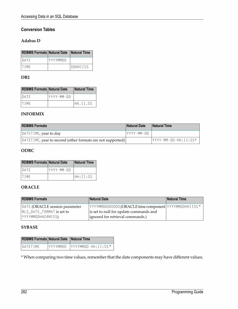
Conversion Tables
Adabas D
Natural TimeNatural DateRDBMS Formats
YYYYMMDDDATE
00HHIISSTIME
DB2
Natural TimeNatural DateRDBMS Formats
YYYY-MM-DDDATE
HH.II.SSTIME
INFORMIX
Natural TimeNatural DateRDBMS Formats
YYYY-MM-DDDATETIME, year to day
YYYY-MM-DD-HH:II:SS*DATETIME, year to second (other formats are not supported)
ODBC
Natural TimeNatural DateRDBMS Formats
YYYY-MM-DDDATE
HH:II:SSTIME
ORACLE
Natural TimeNatural DateRDBMS Formats
YYYYMMDDHHIISS *YYYYMMDD000000 (ORACLE time componentis set to null for update commands andignored for retrieval commands.)
DATE (ORACLE session parameterNLS_DATE_FORMAT is set toYYYYMMDDHH24MISS)
SYBASE
Natural TimeNatural DateRDBMS Formats
YYYYMMDD HH:II:SS *YYYYMMDDDATETIME
*When comparing two time values, remember that the date componentsmay have different values.
Programming Guide282
Accessing Data in an SQL Database

Microsoft SQL Server
Natural TimeNatural DateRDBMS Formats
YYYYMMDD HH:II:SS *YYYYMMDDDATETIME
Obtaining Diagnostic Information about Database Errors
If the database returns an error while being accessed, you can call the non-Natural programCMOSQERR to obtain diagnostic information about the error, using the following syntax:
CALL 'CMOSQERR' parm1 parm2
The parameters are:
DescriptionFormat/LengthParameter
The number of the error returned by the database.I4parm1
The text of the error returned by the database.A70parm2
SQL Authorization
The Natural Configuration Utility allows you to add DBID specific settings of user IDs and pass-words for automatic login to SQL databases. It distinguishes between operating system authentic-ation and database authentication, depending on the current database system. If the Auto loginflag in the SQL Authorization table is set for an SQL DBID then no interactive login prompt willpop up. The login values will be taken from this table row.
Please refer to SQL Assignments in the Configuration Utility documentation for a more detaileddescription of the SQL Authorization table.
283Programming Guide
Accessing Data in an SQL Database

284
27 Accessing Data in a Tamino Database
■ Prerequisite .................................................................................................................................. 286■ DDM and View Definitions with Natural for Tamino ............................................................................... 286■ Natural Statements for Tamino Database Access ................................................................................. 290■ Natural for Tamino Restrictions ......................................................................................................... 294
285

The following topics are covered:
For information about how to configure Natural to work with Tamino, see Natural for Tamino inthe Database Management System Interfaces documentation.
Prerequisite
Tamino stores structureddata-orientedXMLdocuments in containers called doctypes. The doctypesare grouped logically together in so-called collections. Collections are stored in a Tamino database,which is the physical container of data.
The kind of data that can be stored in Tamino and that is to be accessed by Natural for Taminomust be defined in a Tamino XML Schema.
DDM and View Definitions with Natural for Tamino
This section describes the basic concepts of the Tamino XML schema language, Natural DDMsand view definitions and how they interact with Natural for Tamino.
The following topics are covered:
■ Introducing Tamino XML Schema Language■ DDMs from Tamino■ Arrays in DDMs from Tamino■ Example of a DDM■ Definition of Views
Introducing Tamino XML Schema Language
The Tamino XML schema language is used to define a data type-oriented description of thestructure of XML documents. In Tamino, a doctype represents a container for XML documentswith the same root element and the same structure within a collection.
In Tamino, a collection is a container for a set of varying doctypes, so that a collection can be seenas the logical grouping of doctypes that belong together.
In a Tamino XML schema definition, a doctype is defined together with the collection in which itis contained. One Tamino XML schema can define more than one doctype and it can also definedoctypes for more than one collection.
For more information on the Tamino XML schema language, refer to the Tamino documentation.
Programming Guide286
Accessing Data in a Tamino Database

DDMs from Tamino
ForNatural to be able to access a Tamino database, a logical connection between a Tamino doctypeand theNatural data structuresmust be provided. Such a logical connection is called a DDM (datadefinition module).
A Natural DDM generated from a Tamino database is a representation of one doctype defined inone schema. The DDM contains information about the type of each data field and all the necessarystructural information as defined in the corresponding Tamino XML schema. To generate a newDDM, the doctypemust be selected from a list of all doctypes available in a given collection. Sinceone collection is bound to one Natural database ID (DBID), it is necessary to use a second DBIDif a doctype from another collection is to be accessed.
A Tamino XML schema describes data and data structures in a very different way than withNatural data definitions. Therefore, specific mappings are introduced to derive a Natural dataformat from a Tamino XML schema data type.
YoudefineDDMswith theNatural DDMeditor. Formore information about TaminoXML schemamapping, refer toData Conversion for Tamino in theDDMEditor section of theEditorsdocumentation.
For the field attributes defined in a DDM, refer to the DDM editorDDM Editor, Using the DDMEditor section in the Editors documentation.
287Programming Guide
Accessing Data in a Tamino Database

Arrays in DDMs from Tamino
If you define anXML elementwith a maxOccurs value greater than one in the TaminoXMLSchema,then this element can occur as often as this value indicates. Such a construction is mapped eitheron a Natural static array definition or on a Natural X-Array definition. Depending on the type ofthe XML element you are dealing with, the following situations may occur:
■ If the XML element is a complexTypewith complexContent (i.e. it is an element containing otherelements) then the generated corresponding Natural group will be an indexed group.
■ If the XML element is a simpleType (i.e. the element is holding data only) or a complexTypewithsimpleContent (i.e. the element has only data and attributes but no other elements) then thegenerated Natural data field will be an array.
For further information about mapping maxOccurs definitions onto Natural arrays, see Data Con-version for Tamino in the DDM Editor section of the Editors documentation. The array boundariesor the kind of the array (static array or X-Array) can be adapted in a corresponding viewdefinitionas usual.
Example of a DDM
This is an example of an EMPLOYEES DDM generated from a Tamino XML Schema definition.
The schema can, for example, be defined with the Natural demo application SYSEXINS:
DB: 00250 FILE: 00001 - EMPLOYEES-XMLTYPE: XMLCOLLECTION: NATDemoDataSCHEMA: EmployeeDOCTYPE: EmployeeNAMESPACE-PREFIX: xsNAMESPACE-URI: http://www.w3.org/2001/XMLSchemaT L Name F Leng D Remark- -- -------------------------------- - ---------- - -----------G 1 EMPLOYEE FLAGS=MULT_REQUIRED,MULT_ONCE TAG=Employee XPATH=/EmployeeG 2 GROUP$1 FLAGS=GROUP_ATTRIBUTES 3 PERSONNEL-ID A 8 D xs:string FLAGS=ATTR_REQUIRED TAG=@Personnel-ID XPATH=/Employee/@Personnel-IDG 2 GROUP$2 FLAGS=GROUP_SEQUENCE,MULT_REQUIRED,MULT_ONCEG 3 FULL-NAME FLAGS=MULT_OPTIONAL TAG=Full-Name XPATH=/Employee/Full-Name
Programming Guide288
Accessing Data in a Tamino Database

G 4 GROUP$3 FLAGS=GROUP_SEQUENCE,MULT_REQUIRED,MULT_ONCE 5 FIRST-NAME A 20 D xs:string FLAGS=MULT_OPTIONAL TAG=First-Name XPATH=/Employee/Full-Name/First-Name 5 MIDDLE-NAME A 20 D xs:string FLAGS=MULT_OPTIONAL TAG=Middle-Name XPATH=/Employee/Full-Name/Middle-Name 5 MIDDLE-I A 20 D xs:string FLAGS=MULT_OPTIONAL TAG=Middle-I XPATH=/Employee/Full-Name/Middle-I 5 NAME A 20 D xs:string FLAGS=MULT_OPTIONAL TAG=Name XPATH=/Employee/Full-Name/Name . . . 3 LANG A 3 xs:string FLAGS=ARRAY,MULT_OPTIONAL OCC=1:4 TAG=Lang XPATH=/Employee/Lang ↩
Definition of Views
In order to workwith Tamino database fields in aNatural program, youmust specify the requiredfields of the DDM in a Natural view-definition (see the DEFINE DATA statement). Normally, aview is a special subset of the complete data structure as defined in the DDM.
Tamino XML Schema->Natural for Tamino DDM->Natural view-definition
If the view is used to store XML objects, it has to contain all fields that are required to a generatedocuments that are valid according to the corresponding Tamino XML schema definition.
A view for the EMPLOYEES-XMLDDM, where one of the view fields is a static array, might look likethis:
DEFINE DATA LOCAL01 VW VIEW OF EMPLOYEES-XML02 NAME02 CITY02 LANG (1:4)END-DEFINE
289Programming Guide
Accessing Data in a Tamino Database

Natural Statements for Tamino Database Access
The Natural DML statements which are provided for Tamino access can be subdivided into twocategories:
■ pure retrieval statements;■ database modification statements.
The Natural system variable *ISN is mapped on the Tamino ino:id.
Natural for Tamino Retrieval Statements
The following Natural statements can be used for database retrieval:
■ FIND
This statement is used to select those records from a database which meet a specified searchcriterion.
■ GET
This statement is used to select one special record with its unique id from the database.■ READ
This statement is used to select a range of records from a database in a specified sequence.
Not all of the possible options and all of the possible clauses of the retrieval statements can beused for Tamino access. Please read the appropriate section in the Statements documentation fora detailed description.
All statements are internally realized with the Tamino _xquery command verb. Statement clausesare mapped to corresponding Tamino XQuery expressions, e.g. search criteria are mapped toTamino XQuery comparison expressions, sequence specifications are mapped to Tamino XQueryordering expressions with sort direction.
The result set for the FIND and READ statements is determined at start of the loop and remains un-changed throughout the loop.
The following is an example of reading a set of employee records from a Tamino database whereone view field is an array:
Programming Guide290
Accessing Data in a Tamino Database

* READ 5 RECORDS DESCENDING CONTAINING A* STATIC ARRAY IN THE VIEW DEFINE DATA LOCAL01 VW VIEW OF EMPLOYEES-TAMINO02 NAME02 CITY02 LANG (1:4)END-DEFINE*READ(5) VW DESCENDING BY NAME = 'MAYER'
DISPLAY NAME CITY LANG(*)END-READ*END
Natural for Tamino Database Modification Statements
The following database modification statements are provided for use with Natural for Tamino:
■ STORE
This statement is used for inserting a new XML document into the database.■ DELETE
This statement is used for deleting a document from the database. The DELETE statement imple-ments a positioned delete.
For a detailed description of the statements, see the appropriate sections of the Statements docu-mentation.
The DELETE statement is internally realized with the Tamino _delete command verb using thecurrent ino:id, and the STORE statement is implemented with the _process command verb.
Example:
The following example program stores a new employee record with some data in the database:
* STORE NEW EMPLOYEEDEFINE DATA LOCAL01 VW VIEW OF EMPLOYEES-TAMINO02 PERSONNEL-ID02 NAME02 CITY02 LANG (1:3)END-DEFINE** FILL VIEWPERSONNEL-ID := '1230815'NAME := 'KENT'CITY := 'ROME'LANG(1) := 'ENG'
291Programming Guide
Accessing Data in a Tamino Database

LANG(2) := 'GER'LANG(3) := 'SPA'** STORE VIEWSTORE RECORD IN VW*COMMIT*END
If the Tamino XML Schema defines data structures for a doctype as being mandatory, then thesedata structures must also be filled in the view before a STORE statement is issued, otherwise thiswill result in a Tamino error.
Natural for Tamino Logical Transaction Handling
Natural performs database modification operations based on transactions, which means that alldatabase modification requests are processed in logical transaction units. A logical transaction isthe smallest unit of work (as defined by you) which must be performed in its entirety to ensurethat the information contained in the database is logically consistent.
A logical transactionmay consist of one ormoremodification statements (DELETE, STORE) involvingone or more doctypes in the database. A logical transaction may also span multiple Natural pro-grams.
A logical transaction begins when a database modification statement is issued. Natural does thisautomatically. For example, if a FIND loop contains a DELETE statement. The end of a logicaltransaction is determined by an END TRANSACTION statement in the program. This statement ensuresthat all modifications within the transaction have been successfully applied.
Natural for Tamino Error Handling
In addition to Natural's standard error messages there are two special error codes which provideadditional information via a sub-error code.
Error Message NAT8400
NAT8400 Tamino error ... occurred
For this special error an additional sub-code number is shown. This number refers to a Taminoerror message. Please see the TaminoMessages and Codes documentation. The user exit USR6007in library SYSEXT is provided for obtaining diagnostic information in case aNAT8400 error occurs.
Here is an example of usage:
Programming Guide292
Accessing Data in a Tamino Database

DEFINE DATA LOCAL01 VW VIEW OF EMPLOYEES-TAMINO02 NAME02 CITY
01 TAMINO_PARMS02 TAMINO_ERROR_NUM (I4) /* Error number of Tamino error02 TAMINO_ERROR_TEXT (A70) /* Tamino error text02 TAMINO_ERROR_LINE (A253) /* Tamino error message line
END-DEFINE*NAME := 'MEYER'CITY := 'BOSTON'STORE VW*ON ERRORIF *ERROR EQ 8400 /* in case of error 8400 obtain diagnostic informationCALLNAT 'USR6007N' TAMINO_PARMSPRINT 'Error 8400 occurred:'PRINT 'Error Number:' TAMINO_ERROR_NUMPRINT 'Error Text :' TAMINO_ERROR_TEXTPRINT 'Error Line :' TAMINO_ERROR_LINE
END-IFEND-ERROR*END
Error Message NAT8411
NAT8411 HTTP request failed with response code...
The error code from the HTTP server is delivered as additional information. See also REQUESTDOCUMENT statement, Overview of Response Numbers for HTTP/HTTPs Requests.
Example of Natural for Tamino Interacting with a SQL Database
This is a more sophisticated example of Natural for Tamino interacting with an SQL database; itretrieves data from a Tamino database and inserts or updates the corresponding row in an appro-priate table in a SQL database.
** TAMINO DB --> SQL RDBMS EXAMPLE*DEFINE DATA LOCAL* DEFINE VIEW FOR TAMINO01 VW-TAMINO VIEW OF EMPLOYEES-TAMINO02 PERSONNEL-ID02 NAME02 CITY* DEFINE VIEW FOR SQL DATABASE01 VW-SQL VIEW OF EMPLOYEES-SQL
293Programming Guide
Accessing Data in a Tamino Database

02 PERSONNEL_ID02 NAME02 CITYEND-DEFINE** OPEN A TAMINO LOGICAL READ LOOP*TAMINO. READ VW-TAMINO BY NAME** SEARCH RECORD IN SQL DATABASE AND* INSERT A NEW RECORD IF NOT FOUND OR* UPDATE THE EXISTING ONE WITH THE DATA* FROM TAMINO DBSQL. FIND(1) VW-SQL WITH PERSONNEL_ID = PERSONNEL-ID (TAMINO.)
IF NO RECORDS FOUNDPERSONNEL_ID := PERSONNEL-ID (TAMINO.)NAME := NAME (TAMINO.)CITY := CITY (TAMINO.)STORE VW-SQLESCAPE BOTTOM
END-NORECPERSONNEL_ID := PERSONNEL-ID (TAMINO.)NAME := NAME (TAMINO.)CITY := CITY (TAMINO.)UPDATE
END-FIND*END-READ*END TRANSACTION*END
Natural for Tamino Restrictions
There are restrictions concerning the scope of the Tamino XML Schema language that can be usedfor creating schemas for Natural for Tamino DDM generation:
■ Only Tamino XML Schema language constructors and attributes (as mentioned in Tamino XMLSchema Constructors in the DDM Editor section of the Editors documentation) are supported byNatural for Tamino. Other constructors such as xs:any, xs:anyAttribute cannot be applied inTamino XML Schemas if you wish to use them together with Natural for Tamino.
■ The functionality of xs:import is not supported byNatural for Tamino. Thismeans that externalschema componentsmust not be referenced in a TaminoXMLSchema suitable for usage togetherwith Natural. In other words, a doctype definition in a Tamino XML Schema must resolve allreferences within this Tamino XML Schema itself if you are planning to use it together withNatural for Tamino.
Programming Guide294
Accessing Data in a Tamino Database

■ The attribute mixed of the constructor xs:complexType is only supported with its default valuefalse. Natural for Tamino does not support mixed-content document definitions (as set withthe specification mixed="true"). Using mixed="true"will result in an error during DDM gen-eration.
■ The level of nested structures in a Natural for Tamino DDM is limited to 99. A new DDM levelis generated whenever one of the following constructors occurs in the Tamino XML Schema:
xs:elementxs:attributexs:choicexs:allxs:sequence
■ Recursively defined structures in a Tamino XML Schema cannot be used together with Naturalfor Tamino.
■ The Tamino XML Schema language constructor xs:choice is mapped on a Natural group con-taining all alternatives of the choice. To restrict processing to one particular choice, an appropriateview with the required choice has to be created.
■ Natural for Tamino only supports “closed content validation mode”. Tamino XML Schemaswith “open content validation mode” cannot be used together with Natural for Tamino.
■ For the Tamino XML Schema language constructors xs:choice, xs:sequence and xs:all, avalue greater than 1 of the attribute maxOccurs cannot be handled in theNatural data structures.Hence a value greater than 1 will always lead to an error during DDM generation.
■ Natural for Tamino can handle only Tamino objects that are definedwith a TaminoXMLSchemaas a subset of the W3C schema. Especially Natural for Tamino does not support non-XML(tsd:nonXML) data or instances without a defined schema (ino:etc).
295Programming Guide
Accessing Data in a Tamino Database

296

VI Controlling Data Output
This part describes how to proceed if a Natural program is to produce multiple reports. Further-more, it discusses various aspects of how you can control the format of an output report createdwith Natural, that is, the way in which the data are displayed.
Report Specification - (rep) Notation
Layout of an Output Page
Statements DISPLAY and WRITE
Index Notation for Multiple-Value Fields and Periodic Groups
Page Titles, Page Breaks, Blank Lines
Column Headers
Parameters to Influence the Output of Fields
Edit Masks - EM Parameter
Unicode Edit Masks - EMU Parameter
Vertical Displays
297

298
28 Report Specification - (rep) Notation
■ Use of Report Specifications ............................................................................................................ 300■ Statements Concerned ................................................................................................................... 300■ Examples of Report Specification ...................................................................................................... 300
299

(rep) is the output report identifier for which a statement is applicable.
Use of Report Specifications
If a Natural program is to produce multiple reports, the notation (rep)must be specified witheach output statement (see Statements Concerned, below) which is to be used to create output forany report other than the first report (Report 0).
A value of 0 - 31may be specified.
The value for (rep)may also be a logical namewhich has been assigned using the DEFINE PRINTERstatement, see Example 2 below.
Statements Concerned
The notation (rep) can be used with the following output statements:
AT END OF PAGE | AT TOP OF PAGE | DISPLAY | EJECT | FORMAT | NEWPAGE | PRINT | SKIP | SUSPENDIDENTICAL SUPPRESS | WRITE | WRITE TITLE | WRITE TRAILER
Examples of Report Specification
Example 1 - Multiple Reports
DISPLAY (1) NAME ...WRITE (4) NAME ...
Example 2 - Using Logical Names
DEFINE PRINTER (LIST=5) OUTPUT 'LPT1'WRITE (LIST) NAME ...
Programming Guide300
Report Specification - (rep) Notation

29 Layout of an Output Page
■ Statements Influencing a Report Layout ............................................................................................. 302■ General Layout Example ................................................................................................................. 302
301

The following topics are covered:
Statements Influencing a Report Layout
The following statements have an impact on the layout of the report:
FunctionStatement
With this statement, you can specify a page title, that is, text to be output at the topof a page. By default, page titles are centered and not underlined.
WRITE TITLE
With this statement, you can specify a page trailer, that is, text to be output at thebottom of a page. By default, the trailer lines are centered and not underlined.
WRITE TRAILER
With this statement, you can specify any processing that is to be performedwhenevera new page of the report is started. Any output from this processing will be outputbelow the page title.
AT TOP OF PAGE
With this statement, you can specify any processing that is to be performedwheneveran end-of-page condition occurs. Any output from this processing will be outputbelow any page trailer (as specified with the WRITE TRAILER statement).
AT END OF PAGE
With this statement, you specify processing that is to be performed after the firstrecord has been read in a database processing loop. Any output from this processingwill be output before the first field value. See note below.
AT START OF DATA
With this statement, you specify processing that is to be performed after all recordsfor a processing loop have been processed. Any output from this processing will beoutput immediately after the last field value. See note below.
AT END OF DATA
With these statements, you control the format in which the field values that havebeen read are to be output. See section Statements DISPLAY and WRITE.
DISPLAY / WRITE
Note: The relevance of the statements AT START OF DATA and AT END OF DATA for the outputof data is described under Database Access, AT START/END OF DATA Statements. Theother statements listed above are discussed in other sections of the part Controlling DataOutput.
General Layout Example
The following example program illustrates the general layout of an output page:
Programming Guide302
Layout of an Output Page

** Example 'OUTPUX01': Several sections of output************************************************************************DEFINE DATA LOCAL1 EMP-VIEW VIEW OF EMPLOYEES
2 NAME2 FIRST-NAME2 BIRTH
END-DEFINE*WRITE TITLE '********** Page Title **********'WRITE TRAILER '********** Page Trailer **********'*AT TOP OF PAGE
WRITE '===== Top of Page ====='END-TOPPAGEAT END OF PAGE
WRITE '===== End of Page ====='END-ENDPAGE*READ (10) EMP-VIEW BY NAME
/*DISPLAY NAME FIRST-NAME BIRTH (EM=YYYY-MM-DD)/*AT START OF DATA
WRITE '>>>>> Start of Data >>>>>'END-STARTAT END OF DATA
WRITE '<<<<< End of Data <<<<<'END-ENDDATA
END-READEND
Output of Program OUTPUX01:
********** Page Title **********===== Top of Page =====
NAME FIRST-NAME DATEOF
BIRTH-------------------- -------------------- ----------
>>>>> Start of Data >>>>>ABELLAN KEPA 1961-04-08ACHIESON ROBERT 1963-12-24ADAM SIMONE 1952-01-30ADKINSON JEFF 1951-06-15ADKINSON PHYLLIS 1956-09-17ADKINSON HAZEL 1954-03-19ADKINSON DAVID 1946-10-12ADKINSON CHARLIE 1950-03-02ADKINSON MARTHA 1970-01-01ADKINSON TIMMIE 1970-03-03
303Programming Guide
Layout of an Output Page

<<<<< End of Data <<<<<********** Page Trailer **********
===== End of Page =====
Programming Guide304
Layout of an Output Page

30 Statements DISPLAY and WRITE
■ DISPLAY Statement ....................................................................................................................... 306■ WRITE Statement .......................................................................................................................... 307■ Example of DISPLAY Statement ....................................................................................................... 308■ Example of WRITE Statement .......................................................................................................... 308■ Column Spacing - SF Parameter and nX Notation ................................................................................ 309■ Tab Setting - nT Notation ................................................................................................................. 310■ Line Advance - Slash Notation ......................................................................................................... 311■ Further Examples of DISPLAY and WRITE Statements ......................................................................... 314
305

The following topics are covered:
DISPLAY Statement
The DISPLAY statement produces output in column format; that is, the values for one field areoutput in a column underneath one another. If multiple fields are output, that is, if multiplecolumns are produced, these columns are output next to one another horizontally.
The order in which fields are displayed is determined by the sequence in which you specify thefield names in the DISPLAY statement.
The DISPLAY statement in the following program displays for each person first the personnelnumber, then the name and then the job title:
** Example 'DISPLX01': DISPLAY************************************************************************DEFINE DATA LOCAL1 VIEWEMP VIEW OF EMPLOYEES
2 PERSONNEL-ID2 NAME2 BIRTH2 JOB-TITLE
END-DEFINE*READ (3) VIEWEMP BY BIRTH
DISPLAY PERSONNEL-ID NAME JOB-TITLEEND-READEND
Output of Program DISPLX01:
Page 1 04-11-11 14:15:54
PERSONNEL NAME CURRENTID POSITION
--------- -------------------- -------------------------
30020013 GARRET TYPIST30016112 TAILOR WAREHOUSEMAN20017600 PIETSCH SECRETARY
To change the order of the columns that appear in the output report, simply reorder the fieldnames in the DISPLAY statement. For example, if you prefer to list employee names first, then jobtitles followed by personnel numbers, the appropriate DISPLAY statement would be:
Programming Guide306
Statements DISPLAY and WRITE

** Example 'DISPLX02': DISPLAY************************************************************************DEFINE DATA LOCAL1 VIEWEMP VIEW OF EMPLOYEES
2 PERSONNEL-ID2 NAME2 BIRTH2 JOB-TITLE
END-DEFINE*READ (3) VIEWEMP BY BIRTH
DISPLAY NAME JOB-TITLE PERSONNEL-IDEND-READEND
Output of Program DISPLX02:
Page 1 04-11-11 14:15:54
NAME CURRENT PERSONNELPOSITION ID
-------------------- ------------------------- ---------
GARRET TYPIST 30020013TAILOR WAREHOUSEMAN 30016112PIETSCH SECRETARY 20017600
A header is output above each column. Various ways to influence this header are described in thedocument Column Headers.
WRITE Statement
The WRITE statement is used to produce output in free format (that is, not in columns). In contrastto the DISPLAY statement, the following applies to the WRITE statement:
■ If necessary, it automatically creates a line advance; that is, a field or text element that does notfit onto the current output line, is automatically output in the next line.
■ It does not produce any headers.■ The values of a multiple-value field are output next to one another horizontally, and not under-neath one another.
The two example programs shown below illustrate the basic differences between the DISPLAYstatement and the WRITE statement.
You can also use the two statements in combination with one another, as described later in thedocument Vertical Displays, Combining DISPLAY and WRITE .
307Programming Guide
Statements DISPLAY and WRITE

Example of DISPLAY Statement
** Example 'DISPLX03': DISPLAY************************************************************************DEFINE DATA LOCAL1 VIEWEMP VIEW OF EMPLOYEES
2 NAME2 FIRST-NAME2 SALARY (1:3)
END-DEFINE*READ (2) VIEWEMP BY NAME STARTING FROM 'JONES'
DISPLAY NAME FIRST-NAME SALARY (1:3)END-READEND
Output of Program DISPLX03:
Page 1 04-11-11 14:15:54
NAME FIRST-NAME ANNUALSALARY
-------------------- -------------------- ----------
JONES VIRGINIA 460004230039300
JONES MARSHA 500004600042700
Example of WRITE Statement
** Example 'WRITEX01': WRITE************************************************************************DEFINE DATA LOCAL1 VIEWEMP VIEW OF EMPLOYEES
2 NAME2 FIRST-NAME2 SALARY (1:3)
END-DEFINE*READ (2) VIEWEMP BY NAME STARTING FROM 'JONES'
WRITE NAME FIRST-NAME SALARY (1:3)END-READEND
Programming Guide308
Statements DISPLAY and WRITE

Output of Program WRITEX01:
Page 1 04-11-11 14:15:55
JONES VIRGINIA 46000 42300 39300JONES MARSHA 50000 46000 42700
Column Spacing - SF Parameter and nX Notation
By default, the columns output with a DISPLAY statement are separated from one another by onespace.
With the session parameter SF, you can specify the default number of spaces to be inserted betweencolumns output with a DISPLAY statement. You can set the number of spaces to any value from 1to 30.
The parameter can be specified with a FORMAT statement to apply to the whole report, or with aDISPLAY statement at statement level, but not at element level.
With the nX notation in the DISPLAY statement, you can specify the number of spaces (n) to be in-serted between two columns. An nX notation overrides the specification made with the SF para-meter.
** Example 'DISPLX04': DISPLAY (with nX)************************************************************************DEFINE DATA LOCAL1 VIEWEMP VIEW OF EMPLOYEES
2 PERSONNEL-ID2 NAME2 BIRTH2 JOB-TITLE
END-DEFINE*FORMAT SF=3READ (3) VIEWEMP BY BIRTH
DISPLAY PERSONNEL-ID NAME 5X JOB-TITLEEND-READEND
Output of Program DISPLX04:
The above example program produces the following output, where the first two columns areseparated by 3 spaces due to the SF parameter in the FORMAT statement, while the second and thirdcolumns are separated by 5 spaces due to the notation 5X in the DISPLAY statement:
309Programming Guide
Statements DISPLAY and WRITE

Page 1 04-11-11 14:15:54
PERSONNEL NAME CURRENTID POSITION
--------- -------------------- -------------------------
30020013 GARRET TYPIST30016112 TAILOR WAREHOUSEMAN20017600 PIETSCH SECRETARY
The nX notation is also available with the WRITE statement to insert spaces between individualoutput elements:
WRITE PERSONNEL-ID 5X NAME 3X JOB-TITLE
With the above statement, 5 spaces will be inserted between the fields PERSONNEL-ID and NAME,and 3 spaces between NAME and JOB-TITLE.
Tab Setting - nT Notation
With the nT notation, which is availablewith the DISPLAY and the WRITE statement, you can specifythe position where an output element is to be output.
** Example 'DISPLX05': DISPLAY (with nT)************************************************************************DEFINE DATA LOCAL1 VIEWEMP VIEW OF EMPLOYEES
2 NAME2 FIRST-NAME
END-DEFINE*READ (3) VIEWEMP BY NAME STARTING FROM 'JONES'
DISPLAY 5T NAME 30T FIRST-NAMEEND-READEND
Output of Program DISPLX05:
The above program produces the following output, where the field NAME is output starting in the5th position (counted from the left margin of the page), and the field FIRST-NAME starting in the30th position:
Programming Guide310
Statements DISPLAY and WRITE

Page 1 04-11-11 14:15:54
NAME FIRST-NAME-------------------- --------------------
JONES VIRGINIAJONES MARSHAJONES ROBERT
Line Advance - Slash Notation
With a slash (/) in a DISPLAY or WRITE statement, you cause a line advance.
■ In a DISPLAY statement, a slash causes a line advance between fields and within text.■ In a WRITE statement, a slash causes a line advance only when placed between fields; within text,it is treated like an ordinary text character.
When placed between fields, the slash must have a blank on either side.
For multiple line advances, you specify multiple slashes.
Example 1 - Line Advance in DISPLAY Statement:
** Example 'DISPLX06': DISPLAY (with slash '/')************************************************************************DEFINE DATA LOCAL1 VIEWEMP VIEW OF EMPLOYEES
2 NAME2 FIRST-NAME2 DEPARTMENT
END-DEFINE*READ (3) VIEWEMP BY NAME STARTING FROM 'JONES'
DISPLAY NAME / FIRST-NAME 'DEPART-/MENT' DEPARTMENTEND-READEND
Output of Program DISPLX06:
The above DISPLAY statement produces a line advance after each value of the field NAME andwithin the text DEPART-MENT:
311Programming Guide
Statements DISPLAY and WRITE

Page 1 04-11-11 14:15:54
NAME DEPART-FIRST-NAME MENT
-------------------- -------
JONES SALEVIRGINIAJONES MGMTMARSHAJONES TECHROBERT
Example 2 - Line Advance in WRITE Statement:
** Example 'WRITEX02': WRITE (with line advance)************************************************************************DEFINE DATA LOCAL1 VIEWEMP VIEW OF EMPLOYEES
2 NAME2 FIRST-NAME2 DEPARTMENT
END-DEFINE*READ (3) VIEWEMP BY NAME STARTING FROM 'JONES'
WRITE NAME / FIRST-NAME 'DEPART-/MENT' DEPARTMENT //END-READEND
Output of Program WRITEX02:
The above WRITE statement produces a line advance after each value of the field NAME, and a doubleline advance after each value of the field DEPARTMENT, but none within the text DEPART-/MENT:
Page 1 04-11-11 14:15:55
JONESVIRGINIA DEPART-/MENT SALE
JONESMARSHA DEPART-/MENT MGMT
JONESROBERT DEPART-/MENT TECH
Programming Guide312
Statements DISPLAY and WRITE

Example 3 - Line Advance in DISPLAY and WRITE Statements:
** Example 'DISPLX21': DISPLAY (usage of slash '/' in DISPLAY and WRITE)************************************************************************DEFINE DATA LOCAL1 EMPLOY-VIEW VIEW OF EMPLOYEES
2 CITY2 NAME2 FIRST-NAME2 ADDRESS-LINE (1)
END-DEFINE*WRITE TITLE LEFT JUSTIFIED UNDERLINED
*TIME5X 'PEOPLE LIVING IN SALT LAKE CITY'21X 'PAGE:' *PAGE-NUMBER /15X 'AS OF' *DAT4E //
*WRITE TRAILER UNDERLINED 'REGISTER OF' / 'SALT LAKE CITY'*READ (2) EMPLOY-VIEW WITH CITY = 'SALT LAKE CITY'
DISPLAY NAME /FIRST-NAME'HOME/CITY' CITY'STREET/OR BOX NO.' ADDRESS-LINE (1)
SKIP 1END-READEND
Output of Program DISPLX21:
14:15:54.6 PEOPLE LIVING IN SALT LAKE CITY PAGE: 1AS OF 11/11/2004
-------------------------------------------------------------------------------NAME HOME STREET
FIRST-NAME CITY OR BOX NO.-------------------- -------------------- --------------------
ANDERSON SALT LAKE CITY 3701 S. GEORGE MASONJENNY
SAMUELSON SALT LAKE CITY 7610 W. 86TH STREETMARTIN
REGISTER OFSALT LAKE CITY
-------------------------------------------------------------------------------
313Programming Guide
Statements DISPLAY and WRITE
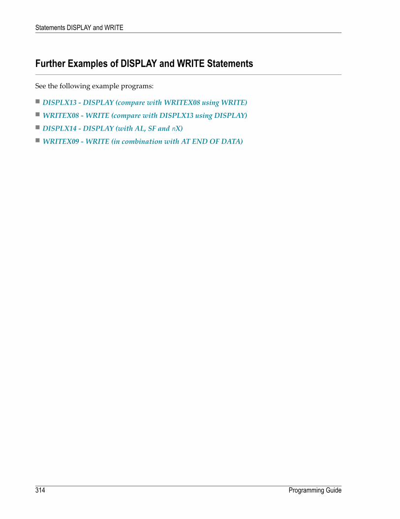
Further Examples of DISPLAY and WRITE Statements
See the following example programs:
■ DISPLX13 - DISPLAY (compare with WRITEX08 using WRITE)■ WRITEX08 - WRITE (compare with DISPLX13 using DISPLAY)■ DISPLX14 - DISPLAY (with AL, SF and nX)■ WRITEX09 - WRITE (in combination with AT END OF DATA)
Programming Guide314
Statements DISPLAY and WRITE
31 Index Notation for Multiple-Value Fields and Periodic
Groups■ Use of Index Notation ..................................................................................................................... 316■ Example of Index Notation in DISPLAY Statement ................................................................................ 316■ Example of Index Notation in WRITE Statement .................................................................................. 317
315

This chapter describes how you can use the index notation (n:n) to specify how many values ofa multiple-value field or how many occurrences of a periodic group are to be output.
Use of Index Notation
With the index notation (n:n) you can specify howmany values of a multiple-value field or howmany occurrences of a periodic group are to be output.
For example, the field INCOME in the DDM EMPLOYEES is a periodic group which keeps a record ofthe annual incomes of an employee for each year he/she has been with the company.
These annual incomes are maintained in chronological order. The income of the most recent yearis in occurrence 1.
If you wanted to have the annual incomes of an employee for the last three years displayed - thatis, occurrences 1 to 3 - you would specify the notation (1:3) after the field name in a DISPLAY orWRITE statement (as shown in the following example program).
Example of Index Notation in DISPLAY Statement
** Example 'DISPLX07': DISPLAY (with index notation)************************************************************************DEFINE DATA LOCAL1 VIEWEMP VIEW OF EMPLOYEES
2 PERSONNEL-ID2 NAME2 BIRTH2 INCOME (1:3)
3 CURR-CODE3 SALARY3 BONUS (1:1)
END-DEFINE*READ (3) VIEWEMP BY BIRTH
DISPLAY PERSONNEL-ID NAME INCOME (1:3)SKIP 1
END-READEND
Output of Program DISPLX07:
Note that a DISPLAY statement outputs multiple values of a multiple-value field underneath oneanother:
Programming Guide316
Index Notation for Multiple-Value Fields and Periodic Groups

Page 1 04-11-11 14:15:54
PERSONNEL NAME INCOMEID
CURRENCY ANNUAL BONUSCODE SALARY
--------- -------------------- -------- ---------- ----------
30020013 GARRET UKL 4200 0UKL 4150 0
0 0
30016112 TAILOR UKL 7450 0UKL 7350 0UKL 6700 0
20017600 PIETSCH USD 22000 0USD 20200 0USD 18700 0
As a WRITE statement displays multiple values horizontally instead of vertically, this may causea line overflow and a - possibly undesired - line advance.
If you use only a single field within a periodic group (for example, SALARY) instead of the entireperiodic group, and if you also insert a slash (/) to cause a line advance (as shown in the followingexample between NAME and JOB-TITLE), the report format becomes manageable.
Example of Index Notation in WRITE Statement
** Example 'WRITEX03': WRITE (with index notation)************************************************************************DEFINE DATA LOCAL1 VIEWEMP VIEW OF EMPLOYEES
2 PERSONNEL-ID2 NAME2 BIRTH2 JOB-TITLE2 SALARY (1:3)
END-DEFINE*READ (3) VIEWEMP BY BIRTH
WRITE PERSONNEL-ID NAME / JOB-TITLE SALARY (1:3)SKIP 1
END-READEND
Output of Program WRITEX03:
317Programming Guide
Index Notation for Multiple-Value Fields and Periodic Groups
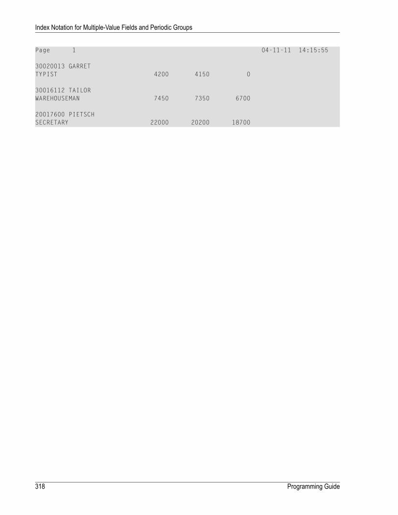
Page 1 04-11-11 14:15:55
30020013 GARRETTYPIST 4200 4150 0
30016112 TAILORWAREHOUSEMAN 7450 7350 6700
20017600 PIETSCHSECRETARY 22000 20200 18700
Programming Guide318
Index Notation for Multiple-Value Fields and Periodic Groups

32 Page Titles, Page Breaks, Blank Lines
■ Default Page Title .......................................................................................................................... 320■ Suppress Page Title - NOTITLE Option .............................................................................................. 320■ Define Your Own Page Title - WRITE TITLE Statement ......................................................................... 321■ Logical Page and Physical Page ....................................................................................................... 324■ Page Size - PS Parameter ............................................................................................................... 326■ Page Advance .............................................................................................................................. 326■ New Page with Title ....................................................................................................................... 329■ Page Trailer - WRITE TRAILER Statement ......................................................................................... 330■ Generating Blank Lines - SKIP Statement ........................................................................................... 332■ AT TOP OF PAGE Statement ........................................................................................................... 333■ AT END OF PAGE Statement ........................................................................................................... 334■ Further Example ............................................................................................................................ 336
319

This chapter describes various ways of controlling page breaks in a report, the output of pagetitles at the top of each report page and the generation of empty lines in an output report.
Default Page Title
For each page output via a DISPLAY or WRITE statement, Natural automatically generates a singledefault title line. This title line contains the page number, the date and the time of day.
Example:
WRITE 'HELLO'END
The above program produces the following output with default page title:
Page 1 04-12-14 13:19:33 HELLO ↩
Suppress Page Title - NOTITLE Option
If you wish your report to be output without page titles, you add the keyword NOTITLE to thestatement DISPLAY or WRITE.
Example - DISPLAY with NOTITLE:
** Example 'DISPLX20': DISPLAY (with NOTITLE)************************************************************************DEFINE DATA LOCAL1 EMPLOY-VIEW VIEW OF EMPLOYEES
2 CITY2 NAME2 FIRST-NAME
END-DEFINE*READ (5) EMPLOY-VIEW BY CITY FROM 'BOSTON'
DISPLAY NOTITLE NAME FIRST-NAME CITYEND-READEND
Output of Program DISPLX20:
Programming Guide320
Page Titles, Page Breaks, Blank Lines

NAME FIRST-NAME CITY-------------------- -------------------- --------------------
SHAW LESLIE BOSTONSTANWOOD VERNON BOSTONCREMER WALT BOSTONPERREAULT BRENDA BOSTONCOHEN JOHN BOSTON
Example - WRITE with NOTITLE:
WRITE NOTITLE 'HELLO'END
The above program produces the following output without page title:
HELLO ↩
Define Your Own Page Title - WRITE TITLE Statement
If you wish a page title of your own to be output instead of the Natural default page title, you usethe statement WRITE TITLE.
The following topics are covered below:
■ Specifying Text for Your Title■ Specifying Empty Lines after the Title■ Title Justification and/or Underlining■ Title with Page Number
Specifying Text for Your Title
With the statement WRITE TITLE, you specify the text for your title (in apostrophes).
WRITE TITLE 'THIS IS MY PAGE TITLE'WRITE 'HELLO'END
The above program produces the following output:
321Programming Guide
Page Titles, Page Breaks, Blank Lines
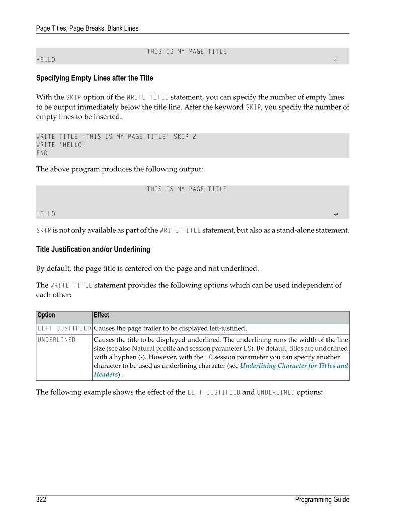
THIS IS MY PAGE TITLE HELLO ↩
Specifying Empty Lines after the Title
With the SKIP option of the WRITE TITLE statement, you can specify the number of empty linesto be output immediately below the title line. After the keyword SKIP, you specify the number ofempty lines to be inserted.
WRITE TITLE 'THIS IS MY PAGE TITLE' SKIP 2WRITE 'HELLO'END
The above program produces the following output:
THIS IS MY PAGE TITLE HELLO ↩
SKIP is not only available as part of the WRITE TITLE statement, but also as a stand-alone statement.
Title Justification and/or Underlining
By default, the page title is centered on the page and not underlined.
The WRITE TITLE statement provides the following options which can be used independent ofeach other:
EffectOption
Causes the page trailer to be displayed left-justified.LEFT JUSTIFIED
Causes the title to be displayed underlined. The underlining runs the width of the linesize (see alsoNatural profile and session parameter LS). By default, titles are underlined
UNDERLINED
with a hyphen (-). However, with the UC session parameter you can specify anothercharacter to be used as underlining character (seeUnderlining Character for Titles andHeaders).
The following example shows the effect of the LEFT JUSTIFIED and UNDERLINED options:
Programming Guide322
Page Titles, Page Breaks, Blank Lines
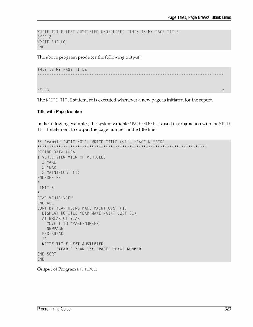
WRITE TITLE LEFT JUSTIFIED UNDERLINED 'THIS IS MY PAGE TITLE'SKIP 2WRITE 'HELLO'END
The above program produces the following output:
THIS IS MY PAGE TITLE ------------------------------------------------------------------------------- HELLO ↩
The WRITE TITLE statement is executed whenever a new page is initiated for the report.
Title with Page Number
In the following examples, the system variable *PAGE-NUMBER is used in conjunctionwith the WRITETITLE statement to output the page number in the title line.
** Example 'WTITLX01': WRITE TITLE (with *PAGE-NUMBER)************************************************************************DEFINE DATA LOCAL1 VEHIC-VIEW VIEW OF VEHICLES
2 MAKE2 YEAR2 MAINT-COST (1)
END-DEFINE*LIMIT 5*READ VEHIC-VIEWEND-ALLSORT BY YEAR USING MAKE MAINT-COST (1)
DISPLAY NOTITLE YEAR MAKE MAINT-COST (1)AT BREAK OF YEAR
MOVE 1 TO *PAGE-NUMBERNEWPAGE
END-BREAK/*WRITE TITLE LEFT JUSTIFIED
'YEAR:' YEAR 15X 'PAGE' *PAGE-NUMBEREND-SORTEND
Output of Program WTITLX01:
323Programming Guide
Page Titles, Page Breaks, Blank Lines

YEAR: 1980 PAGE 1YEAR MAKE MAINT-COST----- -------------------- ----------
1980 RENAULT 200001980 RENAULT 200001980 PEUGEOT 20000
Logical Page and Physical Page
A logical page is the output produced by a Natural program. A physical page is your terminal screenon which the output is displayed; or it may be the piece of paper on which the output is printed.
The size of the logical page is determined by the number of lines output by the Natural program.
If more lines are output than fit onto one screen, the logical page will exceed the physical screen,and the remaining lines will be displayed on the next screen.
Programming Guide324
Page Titles, Page Breaks, Blank Lines

Note: If information you wish to appear at the bottom of the screen (for example, outputcreated by a WRITE TRAILER or AT END OF PAGE statement) is output on the next screen in-stead, reduce the logical page size accordingly (with the session parameter PS, which isdiscussed below).
325Programming Guide
Page Titles, Page Breaks, Blank Lines

Page Size - PS Parameter
With the parameter PS (Page Size for Natural Reports), you determine the maximum number oflines per (logical) page for a report.
When the number of lines specified with the PS parameter is reached, a page advance occurs(unless page advance is controlledwith a NEWPAGE or EJECT statement; seePageAdvance Controlledby EJ Parameter below).
The PS parameter can be set either at session level with the system command GLOBALS, or withina program with the following statements:
At report level:
■ FORMAT PS=nn
At statement level:
■ DISPLAY (PS=nn)
■ WRITE (PS=nn)
■ WRITE TITLE (PS=nn)
■ WRITE TRAILER (PS=nn)
■ INPUT (PS=nn)
Page Advance
A page advance can be triggered by one of the following methods:
■ Page Advance Controlled by EJ Parameter■ Page Advance Controlled by EJECT or NEWPAGE Statements■ Eject/New Page when less than n Lines Left
These methods are discussed below.
Programming Guide326
Page Titles, Page Breaks, Blank Lines

Page Advance Controlled by EJ Parameter
With the session parameter EJ (Page Eject), you determinewhether page ejects are to be performedor not. By default, EJ=ON applies, which means that page ejects will be performed as specified.
If you specify EJ=OFF, page break information will be ignored. This may be useful to save paperduring test runs where page ejects are not needed.
The EJ parameter can be set at session level with the system command GLOBALS; for example:
GLOBALS EJ=OFF
The EJ parameter setting is overridden by the EJECT statement.
Page Advance Controlled by EJECT or NEWPAGE Statements
The following topics are covered below:
■ Page Advance without Title/Header on Next Page■ Page Advance with End/Top-of-Page Processing
Page Advance without Title/Header on Next Page
The EJECT statement causes a page advance without a title or header line being generated on thenext page. A newphysical page is startedwithout any top-of-page or end-of-page processing beingperformed (for example, no WRITE TRAILER or AT END OF PAGE, WRITE TITLE, AT TOP OF PAGEor *PAGE-NUMBER processing).
The EJECT statement overrides the EJ parameter setting.
Page Advance with End/Top-of-Page Processing
The NEWPAGE statement causes a page advance with associated end-of-page and top-of-page pro-cessing. A trailer line will be displayed, if specified. A title line, either default or user-specified,will be displayed on the new page, unless the NOTITLE option has been specified in a DISPLAY orWRITE statement (as described above).
If the NEWPAGE statement is not used, page advance is automatically controlled by the setting ofthe PS parameter; see Page Size - PS Parameter above).
327Programming Guide
Page Titles, Page Breaks, Blank Lines

Eject/New Page when less than n Lines Left
Both the NEWPAGE statement and the EJECT statement provide a WHEN LESS THAN n LINES LEFToption.With this option, you specify a number of lines (n). The NEWPAGE/EJECT statement will thenbe executed if - at the time the statement is processed - less than n lines are available on the currentpage.
Example 1:
FORMAT PS=55...NEWPAGE WHEN LESS THAN 7 LINES LEFT...
In this example, the page size is set to 55 lines.
If only 6 or less lines are left on the current page at the time when the NEWPAGE statement is pro-cessed, the NEWPAGE statement is executed and a page advance occurs. If 7 or more lines are left,the NEWPAGE statement is not executed and no page advance occurs; the page advance then occursdepending on the session parameter PS (Page Size for Natural Reports), that is, after 55 lines.
Example 2:
** Example 'NEWPAX02': NEWPAGE (in combination with EJECT and** parameter PS)************************************************************************DEFINE DATA LOCAL1 EMPLOY-VIEW VIEW OF EMPLOYEES
2 CITY2 NAME2 JOB-TITLE
END-DEFINE*FORMAT PS=15*READ (9) EMPLOY-VIEW BY CITY STARTING FROM 'BOSTON'
AT START OF DATAEJECTWRITE /// 20T '%' (29) /
20T '%%' 47T '%%' /20T '%%' 3X 'REPORT OF EMPLOYEES' 47T '%%' /20T '%%' 3X ' SORTED BY CITY ' 47T '%%' /20T '%%' 47T '%%' /20T '%' (29) /
NEWPAGEEND-STARTAT BREAK OF CITY
NEWPAGE WHEN LESS 3 LINES LEFTEND-BREAKDISPLAY CITY (IS=ON) NAME JOB-TITLE
Programming Guide328
Page Titles, Page Breaks, Blank Lines

END-READEND
New Page with Title
The NEWPAGE statement also provides a WITH TITLE option. If this option is not used, a default titlewill appear at the top of the new page or a WRITE TITLE statement or NOTITLE clause will be ex-ecuted.
The WITH TITLE option of the NEWPAGE statement allows you to override these with a title of yourown choice. The syntax of the WITH TITLE option is the same as for the WRITE TITLE statement.
Example:
NEWPAGE WITH TITLE LEFT JUSTIFIED 'PEOPLE LIVING IN BOSTON:'
The followingprogram illustrates the use of the session parameter PS (Page Size forNatural Reports)and the NEWPAGE statement. Moreover, the system variable *PAGE-NUMBER is used to display thecurrent page number.
** Example 'NEWPAX01': NEWPAGE************************************************************************DEFINE DATA LOCAL1 VIEWEMP VIEW OF EMPLOYEES
2 NAME2 CITY2 DEPT
END-DEFINE*FORMAT PS=20READ (5) VIEWEMP BY CITY STARTING FROM 'M'
DISPLAY NAME 'DEPT' DEPT 'LOCATION' CITYAT BREAK OF CITY
NEWPAGE WITH TITLE LEFT JUSTIFIED'EMPLOYEES BY CITY - PAGE:' *PAGE-NUMBER
END-BREAKEND-READEND
Output of Program NEWPAX01:
Note the position of the page breaks and the title line:
329Programming Guide
Page Titles, Page Breaks, Blank Lines
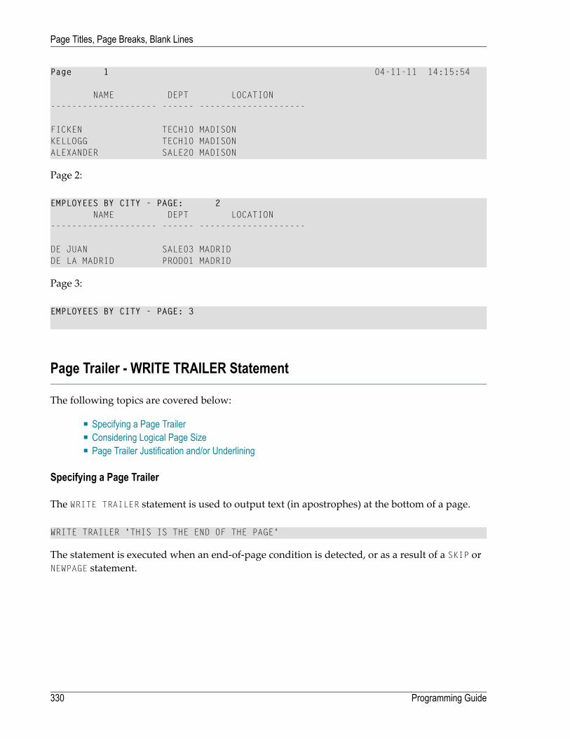
Page 1 04-11-11 14:15:54
NAME DEPT LOCATION-------------------- ------ --------------------
FICKEN TECH10 MADISONKELLOGG TECH10 MADISONALEXANDER SALE20 MADISON
Page 2:
EMPLOYEES BY CITY - PAGE: 2NAME DEPT LOCATION
-------------------- ------ --------------------
DE JUAN SALE03 MADRIDDE LA MADRID PROD01 MADRID
Page 3:
EMPLOYEES BY CITY - PAGE: 3
Page Trailer - WRITE TRAILER Statement
The following topics are covered below:
■ Specifying a Page Trailer■ Considering Logical Page Size■ Page Trailer Justification and/or Underlining
Specifying a Page Trailer
The WRITE TRAILER statement is used to output text (in apostrophes) at the bottom of a page.
WRITE TRAILER 'THIS IS THE END OF THE PAGE'
The statement is executed when an end-of-page condition is detected, or as a result of a SKIP orNEWPAGE statement.
Programming Guide330
Page Titles, Page Breaks, Blank Lines

Considering Logical Page Size
As the end-of-page condition is checked only after an entire DISPLAY or WRITE statement has beenprocessed, it may occur that the logical page size (that is, the number of lines output by a DISPLAYor WRITE statement) causes the physical size of the output page to be exceeded before the WRITETRAILER statement is executed.
To ensure that a page trailer actually appears at the bottom of a physical page, you should set thelogical page size (with the PS session parameter) to a value less than the physical page size.
Page Trailer Justification and/or Underlining
By default, the page trailer is displayed centered on the page and not underlined.
The WRITE TRAILER statement provides the following options which can be used independent ofeach other:
EffectOption
Causes the page trailer to be displayed left justified.LEFT JUSTIFIED
The underlining runs the width of the line size (see also Natural profile and sessionparameter LS). By default, titles are underlined with a hyphen (-). However, with the
UNDERLINED
UC session parameter you can specify another character to be used as underliningcharacter (see Underlining Character for Titles and Headers).
The following examples show the use of the LEFT JUSTIFIED and UNDERLINED options of the WRITETRAILER statement:
Example 1:
WRITE TRAILER LEFT JUSTIFIED UNDERLINED 'THIS IS THE END OF THE PAGE'
Example 2:
** Example 'WTITLX02': WRITE TITLE AND WRITE TRAILER************************************************************************DEFINE DATA LOCAL1 EMPLOY-VIEW VIEW OF EMPLOYEES
2 CITY2 NAME2 FIRST-NAME2 ADDRESS-LINE (1)
END-DEFINE*WRITE TITLE LEFT JUSTIFIED UNDERLINED
*TIME5X 'PEOPLE LIVING IN SALT LAKE CITY'21X 'PAGE:' *PAGE-NUMBER /
331Programming Guide
Page Titles, Page Breaks, Blank Lines

15X 'AS OF' *DAT4E //*WRITE TRAILER UNDERLINED 'REGISTER OF' / 'SALT LAKE CITY'*READ (2) EMPLOY-VIEW WITH CITY = 'SALT LAKE CITY'
DISPLAY NAME /FIRST-NAME'HOME/CITY' CITY'STREET/OR BOX NO.' ADDRESS-LINE (1)
SKIP 1END-READEND
Generating Blank Lines - SKIP Statement
The SKIP statement is used to generate one or more blank lines in an output report.
Example 1 - SKIP in conjunction with WRITE and DISPLAY:
** Example 'SKIPX01': SKIP (in conjunction with WRITE and DISPLAY)************************************************************************DEFINE DATA LOCAL1 EMPLOY-VIEW VIEW OF EMPLOYEES
2 CITY2 NAME2 FIRST-NAME2 ADDRESS-LINE (1)
END-DEFINE*WRITE TITLE LEFT JUSTIFIED UNDERLINED
'PEOPLE LIVING IN SALT LAKE CITY AS OF' *DAT4E 7X'PAGE:' *PAGE-NUMBER
SKIP 3*READ (2) EMPLOY-VIEW WITH CITY = 'SALT LAKE CITY'
DISPLAY NAME / FIRST-NAME CITY ADDRESS-LINE (1)SKIP 1
END-READEND
Programming Guide332
Page Titles, Page Breaks, Blank Lines

Example 2 - SKIP in conjunction with DISPLAY VERT:
** Example 'SKIPX02': SKIP (in conjunction with DISPLAY VERT)************************************************************************DEFINE DATA LOCAL1 EMPLOY-VIEW VIEW OF EMPLOYEES
2 NAME2 FIRST-NAME2 CITY2 JOB-TITLE
END-DEFINE*READ (2) EMPLOY-VIEW WITH JOB-TITLE = 'SECRETARY'
DISPLAY NOTITLE VERTNAME FIRST-NAME / CITY
SKIP 3END-READ*NEWPAGE*READ (2) EMPLOY-VIEW WITH JOB-TITLE = 'SECRETARY'
DISPLAY NOTITLENAME FIRST-NAME / CITY
SKIP 3END-READEND
AT TOP OF PAGE Statement
The AT TOP OF PAGE statement is used to specify any processing that is to be performedwhenevera new page of the report is started.
If the AT TOP OF PAGE processing produces any output, this will be output below the page title(with a skipped line in between).
By default, this output is displayed left-justified on the page.
Example:
** Example 'ATTOPX01': AT TOP OF PAGE************************************************************************DEFINE DATA LOCAL1 EMPLOY-VIEW VIEW OF EMPLOYEES
2 PERSONNEL-ID2 NAME2 MAR-STAT2 BIRTH2 CITY
333Programming Guide
Page Titles, Page Breaks, Blank Lines
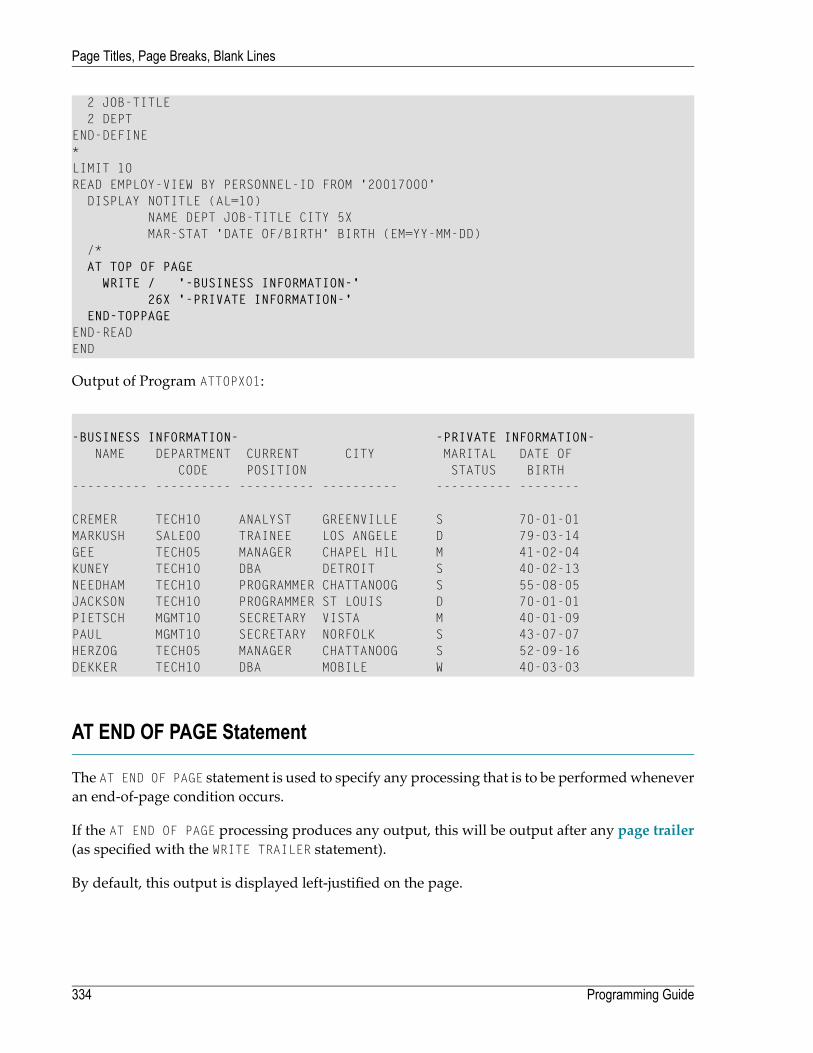
2 JOB-TITLE2 DEPT
END-DEFINE*LIMIT 10READ EMPLOY-VIEW BY PERSONNEL-ID FROM '20017000'
DISPLAY NOTITLE (AL=10)NAME DEPT JOB-TITLE CITY 5XMAR-STAT 'DATE OF/BIRTH' BIRTH (EM=YY-MM-DD)
/*AT TOP OF PAGE
WRITE / '-BUSINESS INFORMATION-'26X '-PRIVATE INFORMATION-'
END-TOPPAGEEND-READEND
Output of Program ATTOPX01:
-BUSINESS INFORMATION- -PRIVATE INFORMATION-NAME DEPARTMENT CURRENT CITY MARITAL DATE OF
CODE POSITION STATUS BIRTH---------- ---------- ---------- ---------- ---------- --------
CREMER TECH10 ANALYST GREENVILLE S 70-01-01MARKUSH SALE00 TRAINEE LOS ANGELE D 79-03-14GEE TECH05 MANAGER CHAPEL HIL M 41-02-04KUNEY TECH10 DBA DETROIT S 40-02-13NEEDHAM TECH10 PROGRAMMER CHATTANOOG S 55-08-05JACKSON TECH10 PROGRAMMER ST LOUIS D 70-01-01PIETSCH MGMT10 SECRETARY VISTA M 40-01-09PAUL MGMT10 SECRETARY NORFOLK S 43-07-07HERZOG TECH05 MANAGER CHATTANOOG S 52-09-16DEKKER TECH10 DBA MOBILE W 40-03-03
AT END OF PAGE Statement
The AT END OF PAGE statement is used to specify any processing that is to be performedwheneveran end-of-page condition occurs.
If the AT END OF PAGE processing produces any output, this will be output after any page trailer(as specified with the WRITE TRAILER statement).
By default, this output is displayed left-justified on the page.
Programming Guide334
Page Titles, Page Breaks, Blank Lines

The same considerations described above for page trailers regarding physical and logical pagesizes and the number of lines output by a DISPLAY or WRITE statement also apply to AT END OFPAGE output.
Example:
** Example 'ATENPX01': AT END OF PAGE (with system function available** via GIVE SYSTEM FUNCTIONS in DISPLAY)************************************************************************DEFINE DATA LOCAL1 EMPLOY-VIEW VIEW OF EMPLOYEES
2 PERSONNEL-ID2 NAME2 JOB-TITLE2 SALARY (1)
END-DEFINE*READ (10) EMPLOY-VIEW BY PERSONNEL-ID = '20017000'
DISPLAY NOTITLE GIVE SYSTEM FUNCTIONSNAME JOB-TITLE 'SALARY' SALARY(1)
/*AT END OF PAGE
WRITE / 24T 'AVERAGE SALARY: ...' AVER(SALARY(1))END-ENDPAGE
END-READEND
Output of Program ATENPX01:
NAME CURRENT SALARYPOSITION
-------------------- ------------------------- ----------
CREMER ANALYST 34000MARKUSH TRAINEE 22000GEE MANAGER 39500KUNEY DBA 40200NEEDHAM PROGRAMMER 32500JACKSON PROGRAMMER 33000PIETSCH SECRETARY 22000PAUL SECRETARY 23000HERZOG MANAGER 48500DEKKER DBA 48000
AVERAGE SALARY: ... 34270 ↩
335Programming Guide
Page Titles, Page Breaks, Blank Lines

Further Example
See the following example program:
■ DISPLX21 - DISPLAY (with slash '/' and compare with WRITE)
Programming Guide336
Page Titles, Page Breaks, Blank Lines
33 Column Headers
■ Default Column Headers ................................................................................................................. 338■ Suppress Default Column Headers - NOHDR Option ............................................................................ 338■ Define Your Own Column Headers .................................................................................................... 339■ Combining NOTITLE and NOHDR .................................................................................................... 340■ Centering of Column Headers - HC Parameter .................................................................................... 340■ Width of Column Headers - HW Parameter ......................................................................................... 340■ Filler Characters for Headers - Parameters FC and GC ......................................................................... 341■ Underlining Character for Titles and Headers - UC Parameter ................................................................ 342■ Suppressing Column Headers - Slash Notation .................................................................................... 343■ Further Examples of Column Headers ............................................................................................... 344
337
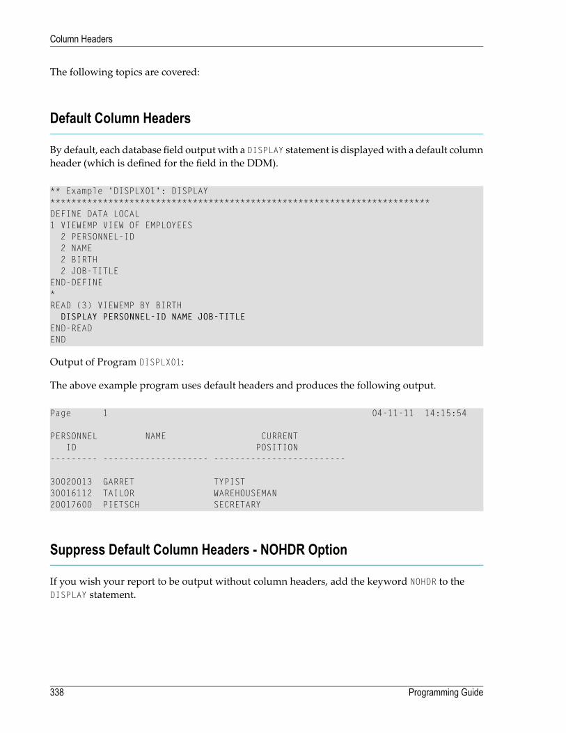
The following topics are covered:
Default Column Headers
By default, each database field outputwith a DISPLAY statement is displayedwith a default columnheader (which is defined for the field in the DDM).
** Example 'DISPLX01': DISPLAY************************************************************************DEFINE DATA LOCAL1 VIEWEMP VIEW OF EMPLOYEES
2 PERSONNEL-ID2 NAME2 BIRTH2 JOB-TITLE
END-DEFINE*READ (3) VIEWEMP BY BIRTH
DISPLAY PERSONNEL-ID NAME JOB-TITLEEND-READEND
Output of Program DISPLX01:
The above example program uses default headers and produces the following output.
Page 1 04-11-11 14:15:54
PERSONNEL NAME CURRENTID POSITION
--------- -------------------- -------------------------
30020013 GARRET TYPIST30016112 TAILOR WAREHOUSEMAN20017600 PIETSCH SECRETARY
Suppress Default Column Headers - NOHDR Option
If you wish your report to be output without column headers, add the keyword NOHDR to theDISPLAY statement.
Programming Guide338
Column Headers

DISPLAY NOHDR PERSONNEL-ID NAME JOB-TITLE
Define Your Own Column Headers
If you wish column headers of your own to be output instead of the default headers, you specify'text' (in apostrophes) immediately before a field, text being the header to be used for the field.
** Example 'DISPLX08': DISPLAY (with column title in 'text')************************************************************************DEFINE DATA LOCAL1 VIEWEMP VIEW OF EMPLOYEES
2 PERSONNEL-ID2 NAME2 BIRTH2 JOB-TITLE
END-DEFINE*READ (3) VIEWEMP BY BIRTH
DISPLAY PERSONNEL-ID'EMPLOYEE' NAME'POSITION' JOB-TITLE
END-READEND
Output of Program DISPLX08:
The above program contains the header EMPLOYEE for the field NAME, and the header POSITION forthe field JOB-TITLE; for the field PERSONNEL-ID, the default header is used. The program producesthe following output:
Page 1 04-11-11 14:15:54
PERSONNEL EMPLOYEE POSITIONID
--------- -------------------- -------------------------
30020013 GARRET TYPIST30016112 TAILOR WAREHOUSEMAN20017600 PIETSCH SECRETARY
339Programming Guide
Column Headers

Combining NOTITLE and NOHDR
To create a report that has neither page title nor column headers, you specify the NOTITLE andNOHDR options together in the following order:
DISPLAY NOTITLE NOHDR PERSONNEL-ID NAME JOB-TITLE
Centering of Column Headers - HC Parameter
By default, column headers are centered above the columns.With the HC parameter, you can influ-ence the placement of column headers.
If you specify
headers will be left-justified.HC=L
headers will be right-justified.HC=R
headers will be centered.HC=C
The HC parameter can be used in a FORMAT statement to apply to the whole report, or it can be usedin a DISPLAY statement at both statement level and element level, for example:
DISPLAY (HC=L) PERSONNEL-ID NAME JOB-TITLE
Width of Column Headers - HW Parameter
With the HW parameter, you determine the width of a column output with a DISPLAY statement.
If you specify
thewidth of a DISPLAY column is determined by either the length of the header text or the lengthof the field, whichever is longer. This also applies by default.
HW=ON
the width of a DISPLAY column is determined only by the length of the field. However, HW=OFFonly applies to DISPLAY statements which do not create headers; that is, either a first DISPLAYstatement with NOHDR option or a subsequent DISPLAY statement.
HW=OFF
The HW parameter can be used in a FORMAT statement to apply to the entire report, or it can be usedin a DISPLAY statement at both statement level and element (field) level.
Programming Guide340
Column Headers

Filler Characters for Headers - Parameters FC and GC
With the FC parameter, you specify the filler characterwhich will appear on either side of a headerproduced by a DISPLAY statement across the full columnwidth if the columnwidth is determinedby the field length and not by the header (see HW parameter above); otherwise FCwill be ignored.
When a group of fields or a periodic group is output via a DISPLAY statement, a group header isdisplayed across all field columns that belong to that group above the headers for the individualfieldswithin the group.With the GC parameter, you can specify the filler characterwhichwill appearon either side of such a group header.
While the FC parameter applies to the headers of individual fields, the GC parameter applies to theheaders for groups of fields.
The parameters FC and GC can be specified in a FORMAT statement to apply to the whole report, orthey can be specified in a DISPLAY statement at both statement level and element (field) level.
** Example 'FORMAX01': FORMAT (with parameters FC, GC)************************************************************************DEFINE DATA LOCAL1 VIEWEMP VIEW OF EMPLOYEES
2 NAME2 INCOME (1:1)
3 CURR-CODE3 SALARY3 BONUS (1:1)
END-DEFINE*FORMAT FC=* GC=$*READ (3) VIEWEMP BY NAME
DISPLAY NAME (FC==) INCOME (1)END-READEND
Output of Program FORMAX01:
Page 1 04-11-11 14:15:54
========NAME======== $$$$$$$$$$$$INCOME$$$$$$$$$$$$
CURRENCY **ANNUAL** **BONUS***CODE SALARY
-------------------- -------- ---------- ----------
ABELLAN PTA 1450000 0ACHIESON UKL 10500 0ADAM FRA 159980 23000
341Programming Guide
Column Headers

Underlining Character for Titles and Headers - UC Parameter
By default, titles and headers are underlined with a hyphen (-).
With the UC parameter, you can specify another character to be used as underlining character.
The UC parameter can be specified in a FORMAT statement to apply to the whole report, or it can bespecified in a DISPLAY statement at both statement level and element (field) level.
** Example 'FORMAX02': FORMAT (with parameter UC)************************************************************************DEFINE DATA LOCAL1 VIEWEMP VIEW OF EMPLOYEES
2 PERSONNEL-ID2 NAME2 BIRTH2 JOB-TITLE
END-DEFINE*FORMAT UC==*WRITE TITLE LEFT JUSTIFIED UNDERLINED 'EMPLOYEES REPORT'SKIP 1READ (3) VIEWEMP BY BIRTH
DISPLAY PERSONNEL-ID (UC=*) NAME JOB-TITLEEND-READEND
In the above program, the UC parameter is specified at program level and at element (field) level:the underlining character specified with the FORMAT statement (=) applies for the whole report -except for the field PERSONNEL-ID, for which a different underlining character (*) is specified.
Output of Program FORMAX02:
EMPLOYEES REPORT===============================================================================
PERSONNEL NAME CURRENTID POSITION
********* ==================== =========================
30020013 GARRET TYPIST30016112 TAILOR WAREHOUSEMAN20017600 PIETSCH SECRETARY
Programming Guide342
Column Headers
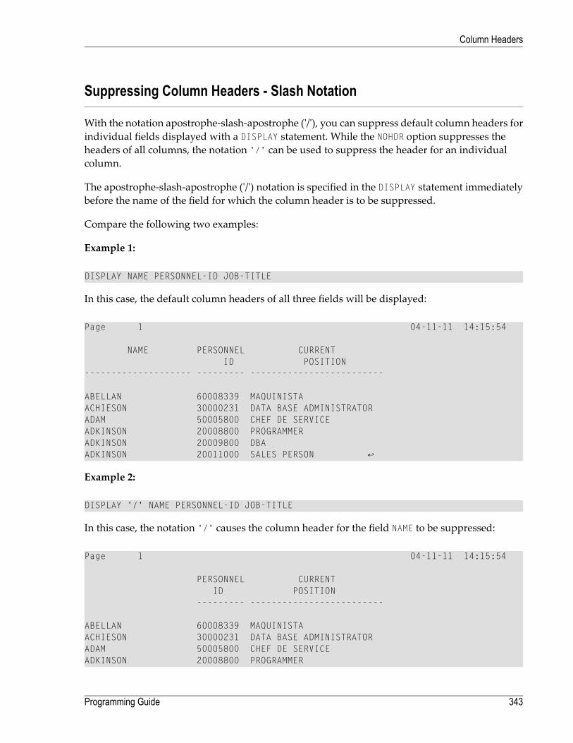
Suppressing Column Headers - Slash Notation
With the notation apostrophe-slash-apostrophe ('/'), you can suppress default column headers forindividual fields displayed with a DISPLAY statement. While the NOHDR option suppresses theheaders of all columns, the notation '/' can be used to suppress the header for an individualcolumn.
The apostrophe-slash-apostrophe ('/') notation is specified in the DISPLAY statement immediatelybefore the name of the field for which the column header is to be suppressed.
Compare the following two examples:
Example 1:
DISPLAY NAME PERSONNEL-ID JOB-TITLE
In this case, the default column headers of all three fields will be displayed:
Page 1 04-11-11 14:15:54 NAME PERSONNEL CURRENT ID POSITION -------------------- --------- ------------------------- ABELLAN 60008339 MAQUINISTA ACHIESON 30000231 DATA BASE ADMINISTRATOR ADAM 50005800 CHEF DE SERVICE ADKINSON 20008800 PROGRAMMER ADKINSON 20009800 DBA ADKINSON 20011000 SALES PERSON ↩
Example 2:
DISPLAY '/' NAME PERSONNEL-ID JOB-TITLE
In this case, the notation '/' causes the column header for the field NAME to be suppressed:
Page 1 04-11-11 14:15:54 PERSONNEL CURRENT ID POSITION --------- ------------------------- ABELLAN 60008339 MAQUINISTA ACHIESON 30000231 DATA BASE ADMINISTRATOR ADAM 50005800 CHEF DE SERVICE ADKINSON 20008800 PROGRAMMER
343Programming Guide
Column Headers
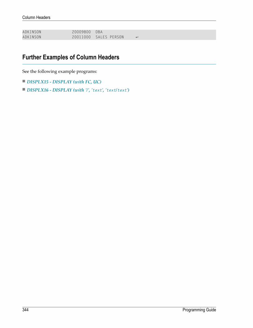
ADKINSON 20009800 DBA ADKINSON 20011000 SALES PERSON ↩
Further Examples of Column Headers
See the following example programs:
■ DISPLX15 - DISPLAY (with FC, UC)■ DISPLX16 - DISPLAY (with '/', 'text', 'text/text')
Programming Guide344
Column Headers

34 Parameters to Influence the Output of Fields
■ Overview of Field-Output-Relevant Parameters ................................................................................... 346■ Leading Characters - LC Parameter .................................................................................................. 346■ Unicode Leading Characters - LCU Parameter .................................................................................... 347■ Insertion Characters - IC Parameter .................................................................................................. 347■ Unicode Insertion Characters - ICU Parameter .................................................................................... 348■ Trailing Characters - TC Parameter ................................................................................................... 348■ Unicode Trailing Characters - TCU Parameter ..................................................................................... 348■ Output Length - AL and NL Parameters .............................................................................................. 349■ Display Length for Output - DL Parameter .......................................................................................... 349■ Sign Position - SG Parameter .......................................................................................................... 351■ Identical Suppress - IS Parameter ..................................................................................................... 353■ Zero Printing - ZP Parameter ........................................................................................................... 355■ Empty Line Suppression - ES Parameter ............................................................................................ 355■ Further Examples of Field-Output-Relevant Parameters ........................................................................ 357
345

This chapter discusses the use of those Natural profile and/or session parameters which you canuse to control the output format of fields.
Overview of Field-Output-Relevant Parameters
Natural provides several profile and/or session parameters you can use to control the format inwhich fields are output:
FunctionParameter
With these session parameters, you can specify characters that are to be displayed beforeor after a field or before a field value.
LC, IC and TC
With these session parameters, you can specify characters in Unicode format that areto be displayed before or after a field or before a field value.
LCU, ICU and TCU
With these session parameters, you can increase or reduce the output length of fields.AL and NL
With this session parameter, you can specify the default output length for analphanumeric map field of format U.
DL
With this session parameter, you can determine whether negative values are to bedisplayed with or without a minus sign.
SG
With this session parameter, you can suppress the display of subsequent identical fieldvalues.
IS
With this profile and session parameter, you can determine whether field values of 0are to be displayed or not.
ZP
With this session parameter, you can suppress the display of empty lines generated bya DISPLAY or WRITE statement.
ES
These parameters are discussed in the following sections.
Leading Characters - LC Parameter
With the session parameter LC, you can specify leading characters that are to be displayed imme-diately before a field that is output with a DISPLAY statement. The width of the output column isenlarged accordingly. You can specify 1 to 10 characters.
By default, values are displayed left-justified in alphanumeric fields and right-justified in numericfields. (These defaults can be changed with the AD parameter; see the Parameter Reference). Whena leading character is specified for an alphanumeric field, the character is therefore displayed im-mediately before the field value; for a numeric field, a number of spaces may occur between theleading character and the field value.
The LC parameter can be used with the following statements:
Programming Guide346
Parameters to Influence the Output of Fields

■ FORMAT
■ DISPLAY
The LC parameter can be set at statement level and at element level.
Unicode Leading Characters - LCU Parameter
The session parameter LCU is identical to the session parameter LC. The difference is that theleading characters are always stored in Unicode format.
This allows you to specify leading characters with mixed characters from different code pages,and assures that always the correct character is displayed independent of the installed systemcode page.
For further information, see Unicode and Code Page Support in the Natural Programming Language,Session Parameters, section EMU, ICU, LCU, TCU versus EM, IC, LC, TC.
The parameters LCU and ICU cannot both be applied to one field.
Insertion Characters - IC Parameter
With the session parameter IC, you specify the characters to be inserted in the column immediatelypreceding the value of a field that is output with a DISPLAY statement. You can specify 1 to 10 charac-ters.
For a numeric field, the insertion characters will be placed immediately before the first significantdigit that is output, with no intervening spaces between the specified character and the field value.For alphanumeric fields, the effect of the IC parameter is the same as that of the LC parameter.
The parameters LC and IC cannot both be applied to one field.
The IC parameter can be used with the following statements:
■ FORMAT
■ DISPLAY
The IC parameter can be set at statement level and at element level.
347Programming Guide
Parameters to Influence the Output of Fields
Unicode Insertion Characters - ICU Parameter
The session parameter ICU is identical to the session parameter IC. The difference is that the insertioncharacters are always stored in Unicode format.
This allows you to specify insertion characters with mixed characters from different code pages,and assures that always the correct character is displayed independent of the installed systemcode page.
For further information, see Unicode and Code Page Support in the Natural Programming Language,Session Parameters, section EMU, ICU, LCU, TCU versus EM, IC, LC, TC.
The parameters LCU and ICU cannot both be applied to one field.
Trailing Characters - TC Parameter
With the session parameter TC, you can specify trailing characters that are to be displayed imme-diately to the right of a field that is outputwith a DISPLAY statement. Thewidth of the output columnis enlarged accordingly. You can specify 1 to 10 characters.
The TC parameter can be used with the following statements:
■ FORMAT
■ DISPLAY
The TC parameter can be set at statement level and at element level.
Unicode Trailing Characters - TCU Parameter
The session parameter TCU is identical to the session parameter TC. The difference is that the trailingcharacters are always stored in Unicode format.
This allows you to specify trailing characters with mixed characters from different code pages,and assures that always the correct character is displayed independent of the installed systemcode page.
For further information, see Unicode and Code Page Support in the Natural Programming Language,Session Parameters, section EMU, ICU, LCU, TCU versus EM, IC, LC, TC.
Programming Guide348
Parameters to Influence the Output of Fields

Output Length - AL and NL Parameters
With the session parameter AL, you can specify the output length for an alphanumeric field; with theNL parameter, you can specify the output length for a numeric field. This determines the length of afield as it will be output, which may be shorter or longer than the actual length of the field (asdefined in the DDM for a database field, or in the DEFINE DATA statement for a user-defined vari-able).
Both parameters can be used with the following statements:
■ FORMAT
■ DISPLAY
■ WRITE
■ INPUT
Both parameters can be set at statement level and at element level.
Note: If an edit mask is specified, it overrides an NL or AL specification. Edit masks are de-scribed in Edit Masks - EM Parameter.
Display Length for Output - DL Parameter
With the session parameter DL, you can specify the display length for a field of format A or U, sincethe display width of a Unicode string can be twice the length of the string, and the user must beable to display the whole string. The default will be the length, for example, for a format/lengthU10, the display length can be 10 to 20, whereas the default length (when DL is not specified) is10.
The session parameter DL can be used with the following statements:
■ FORMAT
■ DISPLAY
■ WRITE
■ INPUT
The session parameter DL can be set at statement level and at element level.
349Programming Guide
Parameters to Influence the Output of Fields

The difference between the session parameters AL and DL is that AL defines the data length of afield whereas DL defines the number of columns which are used on the screen for displaying thefield. The user can scroll in input fields to view the entire content of a field if the value specifiedwith the DL session parameter is less than the length of the field data.
Note: DL is allowed for A-format fields as well. This would allow making the edit controlsize smaller than the content of a field.
Example:
DEFINE DATA LOCAL1 #U1 (U10)1 #U2 (U10)END-DEFINE*#U1 := U'latintxt00'#U2 := U' '*INPUT (AD=M) #U1 #U2END
The above programproduces the following outputwhere the content of the field #U2 is incomplete:
#U1 latintxt00 #U2
When the session parameter DL is used with the field #U2 and is specified accordingly, the contentof this field will be displayed correctly:
DEFINE DATA LOCAL1 #U1 (U10)1 #U2 (U10)END-DEFINE*#U1 := U'latintxt00'#U2 := U' '*INPUT (AD=M) #U1 #U2 (DL=20)END
Result:
Programming Guide350
Parameters to Influence the Output of Fields

#U1 latintxt00 #U2
Sign Position - SG Parameter
With the session parameter SG, you can determine whether or not a sign position is to be allocatedfor numeric fields.
■ By default, SG=ON applies, which means that a sign position is allocated for numeric fields.■ If you specify SG=OFF, negative values in numeric fields will be output without a minus sign (-).
The SG parameter can be used with the following statements:
■ FORMAT
■ DISPLAY
■ WRITE
■ INPUT
The SG parameter can be set at both statement level and element level.
Note: If an edit mask is specified, it overrides an SG specification. Edit masks are describedin Edit Masks - EM Parameter.
Example Program without Parameters
** Example 'FORMAX03': FORMAT (without FORMAT and compare with FORMAX04)************************************************************************DEFINE DATA LOCAL1 VIEWEMP VIEW OF EMPLOYEES
2 NAME2 FIRST-NAME2 SALARY (1:1)2 BONUS (1:1,1:1)
END-DEFINE*READ (5) VIEWEMP BY NAME STARTING FROM 'JONES'
DISPLAY NAMEFIRST-NAMESALARY (1:1)BONUS (1:1,1:1)
END-READEND
351Programming Guide
Parameters to Influence the Output of Fields

The above program contains no parameter settings and produces the following output:
Page 1 04-11-11 11:11:11
NAME FIRST-NAME ANNUAL BONUSSALARY
-------------------- -------------------- ---------- ----------
JONES VIRGINIA 46000 9000JONES MARSHA 50000 0JONES ROBERT 31000 0JONES LILLY 24000 0JONES EDWARD 37600 0
Example Program with Parameters AL, NL, LC, IC and TC
In this example, the session parameters AL, NL, LC, IC and TC are used.
** Example 'FORMAX04': FORMAT (with parameters AL, NL, LC, TC, IC and** compare with FORMAX03)************************************************************************DEFINE DATA LOCAL1 VIEWEMP VIEW OF EMPLOYEES
2 NAME2 FIRST-NAME2 SALARY (1:1)2 BONUS (1:1,1:1)
END-DEFINE*FORMAT AL=10 NL=6*READ (5) VIEWEMP BY NAME STARTING FROM 'JONES'
DISPLAY NAME (LC=*)FIRST-NAME (TC=*)SALARY (1:1) (IC=$)BONUS (1:1,1:1) (LC=>)
END-READEND
The above program produces the following output. Compare the layout of this output with thatof the previous program to see the effect of the individual parameters:
Programming Guide352
Parameters to Influence the Output of Fields

Page 1 04-11-11 11:11:11
NAME FIRST-NAME ANNUAL BONUSSALARY
----------- ----------- -------- --------
*JONES VIRGINIA * $46000 > 9000*JONES MARSHA * $50000 > 0*JONES ROBERT * $31000 > 0*JONES LILLY * $24000 > 0*JONES EDWARD * $37600 > 0
As you can see in the above example, any output length you specify with the AL or NL parameterdoes not include any characters specified with the LC, IC and TC parameters: the width of the NAMEcolumn, for example, is 11 characters - 10 for the field value (AL=10) plus 1 leading character.
The width of the SALARY and BONUS columns is 8 characters - 6 for the field value (NL=6), plus 1leading/inserted character, plus 1 sign position (because SG=ON applies).
Identical Suppress - IS Parameter
With the session parameter IS, you can suppress the display of identical information in successivelines created by a WRITE or DISPLAY statement.
■ By default, IS=OFF applies, which means that identical field values will be displayed.■ If IS=ON is specified, a value which is identical to the previous value of that field will not bedisplayed.
The IS parameter can be specified
■ with a FORMAT statement to apply to the whole report, or■ in a DISPLAY or WRITE statement at both statement level and element level.
The effect of the parameter IS=ON can be suspended for one record by using the statement SUSPENDIDENTICAL SUPPRESS; see the Statements documentation for details.
Compare the output of the following two example programs to see the effect of the IS parameter.In the second one, the display of identical values in the NAME field is suppressed.
353Programming Guide
Parameters to Influence the Output of Fields

Example Program without IS Parameter
** Example 'FORMAX05': FORMAT (without parameter IS** and compare with FORMAX06)************************************************************************DEFINE DATA LOCAL1 VIEWEMP VIEW OF EMPLOYEES
2 NAME2 FIRST-NAME
END-DEFINE*READ (3) VIEWEMP BY NAME STARTING FROM 'JONES'
DISPLAY NAME FIRST-NAMEEND-READEND
The above program produces the following output:
Page 1 04-11-11 11:11:11 NAME FIRST-NAME -------------------- -------------------- JONES VIRGINIA JONES MARSHA JONES ROBERT ↩
Example Program with IS Parameter
** Example 'FORMAX06': FORMAT (with parameter IS** and compare with FORMAX05)************************************************************************DEFINE DATA LOCAL1 VIEWEMP VIEW OF EMPLOYEES
2 NAME2 FIRST-NAME
END-DEFINE*FORMAT IS=ON*READ (3) VIEWEMP BY NAME STARTING FROM 'JONES'
DISPLAY NAME FIRST-NAMEEND-READEND
The above program produces the following output:
Programming Guide354
Parameters to Influence the Output of Fields

Page 1 04-11-11 11:54:01
NAME FIRST-NAME-------------------- --------------------
JONES VIRGINIAMARSHAROBERT
Zero Printing - ZP Parameter
With the profile and session parameter ZP, you determine how a field value of zero is to be dis-played.
■ By default, ZP=ON applies, which means that one 0 (for numeric fields) or all zeros (for timefields) will be displayed for each field value that is zero.
■ If you specify ZP=OFF, the display of each field value which is zero will be suppressed.
The ZP parameter can be specified
■ with a FORMAT statement to apply to the whole report, or■ in a DISPLAY or WRITE statement at both statement level and element level.
Compare the output of the following two example programs to see the effect of the parametersZP and ES.
Empty Line Suppression - ES Parameter
With the session parameter ES, you can suppress the output of empty lines created by a DISPLAYor WRITE statement.
■ By default, ES=OFF applies, whichmeans that lines containing all blank valueswill be displayed.■ If ES=ON is specified, a line resulting from a DISPLAY or WRITE statement which contains all blankvalues will not be displayed. This is particularly useful when displaying multiple-value fieldsor fields which are part of a periodic group if a large number of empty lines are likely to beproduced.
The ES parameter can be specified
■ with a FORMAT statement to apply to the whole report, or■ in a DISPLAY or WRITE statement at statement level.
355Programming Guide
Parameters to Influence the Output of Fields

Note: To achieve empty suppression for numeric values, in addition to ES=ON the parameterZP=OFFmust also be set for the fields concerned in order to have null values turned intoblanks and thus not output either.
Compare the output of the following two example programs to see the effect of the parametersZP and ES.
Example Program without Parameters ZP and ES
** Example 'FORMAX07': FORMAT (without parameter ES and ZP** and compare with FORMAX08)************************************************************************DEFINE DATA LOCAL1 VIEWEMP VIEW OF EMPLOYEES
2 NAME2 FIRST-NAME2 BONUS (1:2,1:1)
END-DEFINE*READ (4) VIEWEMP BY NAME STARTING FROM 'JONES'
DISPLAY NAME FIRST-NAME BONUS (1:2,1:1)END-READEND
The above program produces the following output:
Page 1 04-11-11 11:58:23
NAME FIRST-NAME BONUS-------------------- -------------------- ----------
JONES VIRGINIA 90006750
JONES MARSHA 00
JONES ROBERT 00
JONES LILLY 00
Programming Guide356
Parameters to Influence the Output of Fields

Example Program with Parameters ZP and ES
** Example 'FORMAX08': FORMAT (with parameters ES and ZP** and compare with FORMAX07)************************************************************************DEFINE DATA LOCAL1 VIEWEMP VIEW OF EMPLOYEES
2 NAME2 FIRST-NAME2 BONUS (1:2,1:1)
END-DEFINE*FORMAT ES=ON*READ (4) VIEWEMP BY NAME STARTING FROM 'JONES'
DISPLAY NAME FIRST-NAME BONUS (1:2,1:1)(ZP=OFF)END-READEND
The above program produces the following output:
Page 1 04-11-11 11:59:09
NAME FIRST-NAME BONUS-------------------- -------------------- ----------
JONES VIRGINIA 90006750
JONES MARSHAJONES ROBERTJONES LILLY
Further Examples of Field-Output-Relevant Parameters
For further examples of the parameters LC, IC, TC, AL, NL, IS, ZP and ES, and the SUSPEND IDENTICALSUPPRESS statement, see the following example programs:
■ DISPLX17 - DISPLAY (with NL, AL, IC, LC, TC)■ DISPLX18 - DISPLAY (using default settings for SF, AL, UC, LC, IC, TC and compare withDISPLX19)
■ DISPLX19 - DISPLAY (with SF, AL, LC, IC, TC and compare with DISPLX18)■ SUSPEX01 - SUSPEND IDENTICAL SUPPRESS (in conjunction with parameters IS, ES, ZPin DISPLAY)
■ SUSPEX02 - SUSPEND IDENTICAL SUPPRESS (in conjunction with parameters IS, ES, ZPin DISPLAY). Identical to SUSPEX01, but with IS=OFF.
357Programming Guide
Parameters to Influence the Output of Fields

■ COMPRX03 - COMPRESS
Programming Guide358
Parameters to Influence the Output of Fields

35 Code Page Edit Masks - EM Parameter
■ Use of EM Parameter ..................................................................................................................... 360■ Edit Masks for Numeric Fields .......................................................................................................... 360■ Edit Masks for Alphanumeric Fields ................................................................................................... 361■ Length of Fields ............................................................................................................................. 361■ Edit Masks for Date and Time Fields .................................................................................................. 362■ Customizing Separator Character Displays ......................................................................................... 362■ Examples of Edit Masks .................................................................................................................. 364■ Further Examples of Edit Masks ....................................................................................................... 366
359
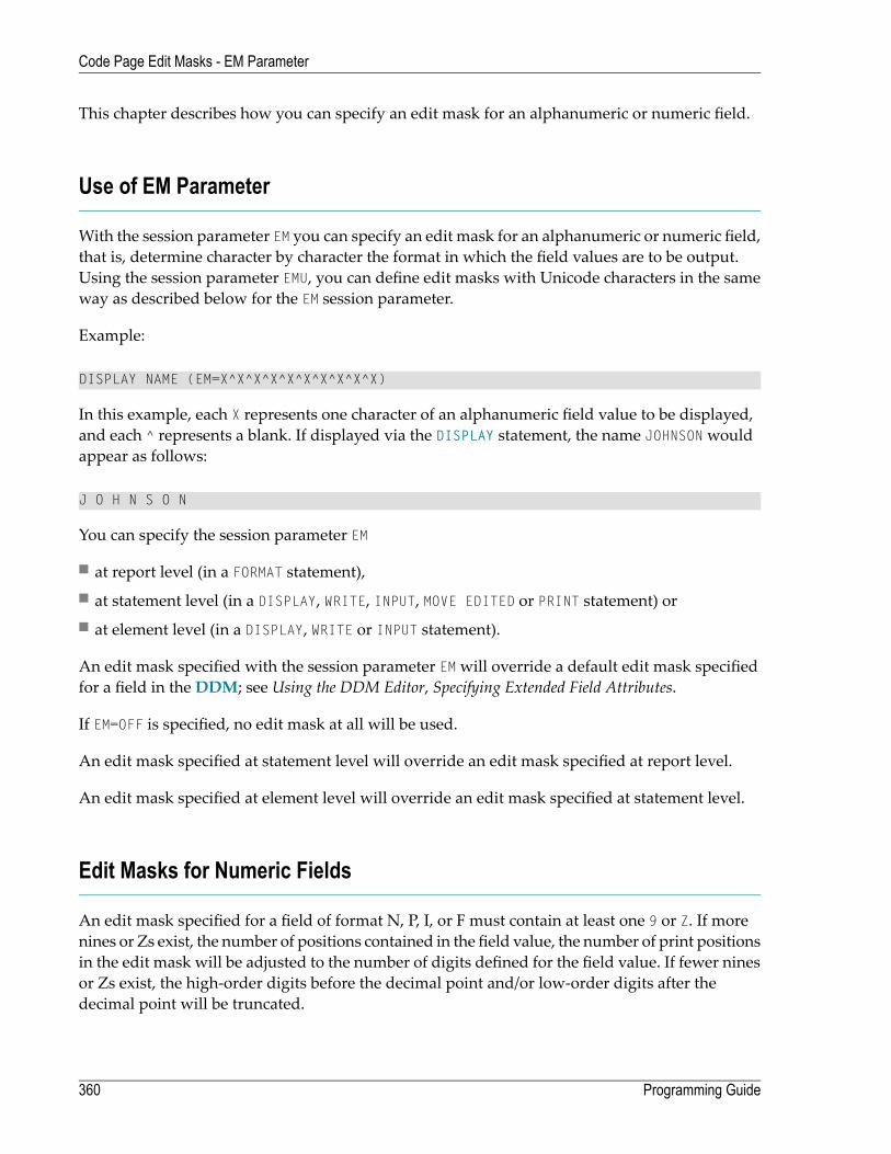
This chapter describes how you can specify an edit mask for an alphanumeric or numeric field.
Use of EM Parameter
With the session parameter EM you can specify an edit mask for an alphanumeric or numeric field,that is, determine character by character the format in which the field values are to be output.Using the session parameter EMU, you can define edit masks with Unicode characters in the sameway as described below for the EM session parameter.
Example:
DISPLAY NAME (EM=X^X^X^X^X^X^X^X^X^X)
In this example, each X represents one character of an alphanumeric field value to be displayed,and each ^ represents a blank. If displayed via the DISPLAY statement, the name JOHNSONwouldappear as follows:
J O H N S O N
You can specify the session parameter EM
■ at report level (in a FORMAT statement),■ at statement level (in a DISPLAY, WRITE, INPUT, MOVE EDITED or PRINT statement) or■ at element level (in a DISPLAY, WRITE or INPUT statement).
An edit mask specified with the session parameter EMwill override a default edit mask specifiedfor a field in the DDM; see Using the DDM Editor, Specifying Extended Field Attributes.
If EM=OFF is specified, no edit mask at all will be used.
An edit mask specified at statement level will override an edit mask specified at report level.
An edit mask specified at element level will override an edit mask specified at statement level.
Edit Masks for Numeric Fields
An edit mask specified for a field of format N, P, I, or F must contain at least one 9 or Z. If morenines or Zs exist, the number of positions contained in the field value, the number of print positionsin the edit mask will be adjusted to the number of digits defined for the field value. If fewer ninesor Zs exist, the high-order digits before the decimal point and/or low-order digits after thedecimal point will be truncated.
Programming Guide360
Code Page Edit Masks - EM Parameter

For further information, see session parameter EM, Edit Masks for Numeric Fields in the ParameterReference documentation.
Edit Masks for Alphanumeric Fields
Edit masks for alphanumeric fields must include an X for each alphanumeric character that is tobe output.
With a few exceptions, you may add leading, trailing and insertion characters (with or withoutenclosing them in apostrophes).
The circumflex character (^) is used to insert blanks in edit mask for both numeric and alphanu-meric fields.
For further information, see session parameter EM,EditMasks for Alphanumeric Fields in theParameterReference documentation.
Length of Fields
It is important to be aware of the length of the field to which you assign an edit mask.
■ If the edit mask is longer than the field, this will yield unexpected results.■ If the edit mask is shorter than the field, the field output will be truncated to just those positionsspecified in the edit mask.
Examples:
Assuming an alphanumeric field that is 12 characters long and the field value to be output isJOHNSON, the following edit masks will yield the following results:
OutputEdit Mask
J.O.H.N.SEM=X.X.X.X.X
****JOHNSO**EM=****XXXXXX****
361Programming Guide
Code Page Edit Masks - EM Parameter

Edit Masks for Date and Time Fields
Edit masks for date fields can include the characters D (day), M (month) and Y (year) in variouscombinations.
Edit masks for time fields can include the characters H (hour), I (minute), S (second) and T (tenthof a second) in various combinations.
In conjunctionwith editmasks for date and time fields, see also the date and time system variables.
Customizing Separator Character Displays
Natural programs are used in business applications all over the world. Depending on the localconventions, it is usual to present numeric data fields and those with a date or time content in aspecial output style, when displayed in I/O statements. The different appearance should not berealized by alternate program coding that is processed selectively as a function of the locale wherethe program is being executed, but should be carried outwith the sameprogram image in conjunc-tion with a set of runtime parameters to specify the decimal point character and the “thousandsseparator character”.
The following topics are covered below:
■ Decimal Separator■ Dynamic Thousands Separator■ Examples
Decimal Separator
The Natural parameter DC is available to specify the character to be inserted in place of any char-acters used to represent the decimal separator (also called “radix” character) in edit masks. Thisparameter enables the users of a Natural program or application to choose any (special) characterto separate the integer positions from the decimal positions of a numeric data item and enables,for example, U.S. shops to use the decimal point (.) and European shops to use the comma (,).
Programming Guide362
Code Page Edit Masks - EM Parameter
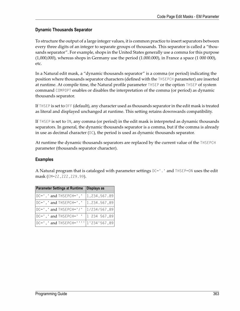
Dynamic Thousands Separator
To structure the output of a large integer values, it is commonpractice to insert separators betweenevery three digits of an integer to separate groups of thousands. This separator is called a “thou-sands separator”. For example, shops in the United States generally use a comma for this purpose(1,000,000), whereas shops in Germany use the period (1.000.000), in France a space (1 000 000),etc.
In a Natural edit mask, a “dynamic thousands separator” is a comma (or period) indicating theposition where thousands separator characters (definedwith the THSEPCH parameter) are insertedat runtime. At compile time, the Natural profile parameter THSEP or the option THSEP of systemcommand COMPOPT enables or disables the interpretation of the comma (or period) as dynamicthousands separator.
If THSEP is set to OFF (default), any character used as thousands separator in the edit mask is treatedas literal and displayed unchanged at runtime. This setting retains downwards compatibility.
If THSEP is set to ON, any comma (or period) in the edit mask is interpreted as dynamic thousandsseparators. In general, the dynamic thousands separator is a comma, but if the comma is alreadyin use as decimal character (DC), the period is used as dynamic thousands separator.
At runtime the dynamic thousands separators are replaced by the current value of the THSEPCHparameter (thousands separator character).
Examples
A Natural program that is cataloged with parameter settings DC='.' and THSEP=ON uses the editmask (EM=ZZ,ZZZ,ZZ9.99).
Displays asParameter Settings at Runtime
1,234,567.89DC='.' and THSEPCH=','
1.234.567,89DC=',' and THSEPCH='.'
1/234/567,89DC=',' and THSEPCH='/'
1 234 567,89DC=',' and THSEPCH=' '
1'234'567,89DC=',' and THSEPCH=''''
363Programming Guide
Code Page Edit Masks - EM Parameter

Examples of Edit Masks
Some examples of edit masks, along with possible output they produce, are provided below.
In addition, the abbreviated notation for each editmask is given. You can use either the abbreviatedor the long notation.
Output BOutput AAbbreviationEdit Mask
005.40367.32EM=9(3).9(2)EM=999.99
5790EM=Z(5)9(1)EM=ZZZZZ9
A 19379B LUEEM=X(1)^X(5)EM=X^XXXXX
AAB...01BLU...EEM=X(3)...X(2)EM=XXX...XX
12.22.8601.05.87*EM=MM.DD.YY
14.32.54.308.54.12.7**EM=HH.II.SS.T
* Use a date system variable.
** Use a time system variable.
For further information about edit masks, see the session parameter EM in the Parameter Reference.
Example Program without EM Parameters
** Example 'EDITMX01': Edit mask (using default edit masks)************************************************************************DEFINE DATA LOCAL1 VIEWEMP VIEW OF EMPLOYEES
2 NAME2 JOB-TITLE2 SALARY (1:3)2 CITY
END-DEFINE*READ (3) VIEWEMP BY NAME STARTING FROM 'JONES'
DISPLAY 'N A M E' NAME /'OCCUPATION' JOB-TITLE'SALARY' SALARY (1:3)'LOCATION' CITY
SKIP 1END-READEND
Output of Program EDITMX01:
The output of this program shows the default edit masks available.
Programming Guide364
Code Page Edit Masks - EM Parameter

Page 1 04-11-11 14:15:54
N A M E SALARY LOCATIONOCCUPATION
------------------------- ---------- --------------------
JONES 46000 TULSAMANAGER 42300
39300
JONES 50000 MOBILEDIRECTOR 46000
42700
JONES 31000 MILWAUKEEPROGRAMMER 29400
27600
Example Program with EM Parameters
** Example 'EDITMX02': Edit mask (using EM)************************************************************************DEFINE DATA LOCAL1 VIEWEMP VIEW OF EMPLOYEES
2 NAME2 FIRST-NAME2 JOB-TITLE2 SALARY (1:3)
END-DEFINE*READ (3) VIEWEMP BY NAME STARTING FROM 'JONES'DISPLAY 'N A M E' NAME (EM=X^X^X^X^X^X^X^X^X^X^X^X^X^X^X) /
FIRST-NAME (EM=...X(10)...)'OCCUPATION' JOB-TITLE (EM=' ___ 'X(12))'SALARY' SALARY (1:3) (EM=' USD 'ZZZ,999)
SKIP 1END-READEND
Output of Program EDITMX02:
Compare the outputwith that of the previous program (Example Programwithout EMParameters)to see how the EM specifications affect the way the fields are displayed.
365Programming Guide
Code Page Edit Masks - EM Parameter

Page 1 04-11-11 14:15:54
N A M E OCCUPATION SALARYFIRST-NAME
----------------------------- ---------------- -----------
J O N E S ___ MANAGER USD 46,000..VIRGINIA ... USD 42,300
USD 39,300
J O N E S ___ DIRECTOR USD 50,000..MARSHA ... USD 46,000
USD 42,700
J O N E S ___ PROGRAMMER USD 31,000..ROBERT ... USD 29,400
USD 27,600
Further Examples of Edit Masks
See the following example programs:
■ EDITMX03 - Edit mask (different EM for alpha-numeric fields)■ EDITMX04 - Edit mask (different EM for numeric fields)■ EDITMX05 - Edit mask (EM for date and time system variables)
Programming Guide366
Code Page Edit Masks - EM Parameter
36 Unicode Edit Masks - EMU Parameter
Unicode edit masks can be used similar to code page edit masks. The difference is that the editmask is always stored in Unicode format.
This allows you to specify editmaskswithmixed characters fromdifferent code pages and assuresthat always the correct character is displayed, independent of the installed system code page.
For the general usage of edit masks, see Edit Masks - EM Parameter.
For information on the session parameter EMU, see EMU - Unicode Edit Mask (in the Parameter Ref-erence).
367

368
37 Vertical Displays
■ Creating Vertical Displays ................................................................................................................ 370■ Combining DISPLAY and WRITE ...................................................................................................... 370■ Tab Notation - T*field ...................................................................................................................... 371■ Positioning Notation x/y .................................................................................................................. 372■ DISPLAY VERT Statement .............................................................................................................. 373■ Further Example of DISPLAY VERT with WRITE Statement ................................................................... 379
369

This chapter describes how you can combine the features of the statements DISPLAY and WRITE toproduce vertical displays of field values.
Creating Vertical Displays
There are two ways of creating vertical displays:
■ You can use a combination of the statements DISPLAY and WRITE.■ You can use the VERT option of the DISPLAY statement.
Combining DISPLAY and WRITE
As described in Statements DISPLAY and WRITE, the DISPLAY statement normally presents thedata in columnswith default headers, while the WRITE statement presents data horizontallywithoutheaders.
You can combine the features of the two statements to produce vertical displays of field values.
The DISPLAY statement produces the values of different fields for the same record across the pagewith a column for each field. The field values for each record are displayed below the values forthe previous record.
By using a WRITE statement after a DISPLAY statement, you can insert text and/or field values spe-cified in the WRITE statement between records displayed via the DISPLAY statement.
The following program illustrates the combination of DISPLAY and WRITE:
** Example 'WRITEX04': WRITE (in combination with DISPLAY)************************************************************************DEFINE DATA LOCAL1 VIEWEMP VIEW OF EMPLOYEES
2 NAME2 JOB-TITLE2 CITY2 DEPT
END-DEFINE*READ (3) VIEWEMP BY CITY STARTING FROM 'SAN FRANCISCO'
DISPLAY NAME JOB-TITLEWRITE 22T 'DEPT:' DEPTSKIP 1
END-READEND
Programming Guide370
Vertical Displays

Output of Program WRITEX04:
Page 1 04-11-11 14:15:55
NAME CURRENTPOSITION
-------------------- -------------------------
KOLENCE MANAGERDEPT: TECH05
GOSDEN ANALYSTDEPT: TECH10
WALLACE SALES PERSONDEPT: SALE20
Tab Notation - T*field
In the previous example, the position of the field DEPT is determined by the tab notation nT (in thiscase 20T, which means that the display begins in column 20 on the screen).
Field values specified in a WRITE statement can be lined up automaticallywith field values specifiedin the first DISPLAY statement of the program by using the tab notation T*field (where field isthe name of the field to which the field is to be aligned).
In the following program, the output produced by the WRITE statement is aligned to the fieldJOB-TITLE by using the notation T*JOB-TITLE:
** Example 'WRITEX05': WRITE (in combination with DISPLAY)************************************************************************DEFINE DATA LOCAL1 VIEWEMP VIEW OF EMPLOYEES
2 NAME2 JOB-TITLE2 DEPT2 CITY
END-DEFINE*READ (3) VIEWEMP BY CITY STARTING FROM 'SAN FRANCISCO'
DISPLAY NAME JOB-TITLEWRITE T*JOB-TITLE 'DEPT:' DEPTSKIP 1
END-READEND
Output of Program WRITEX05:
371Programming Guide
Vertical Displays
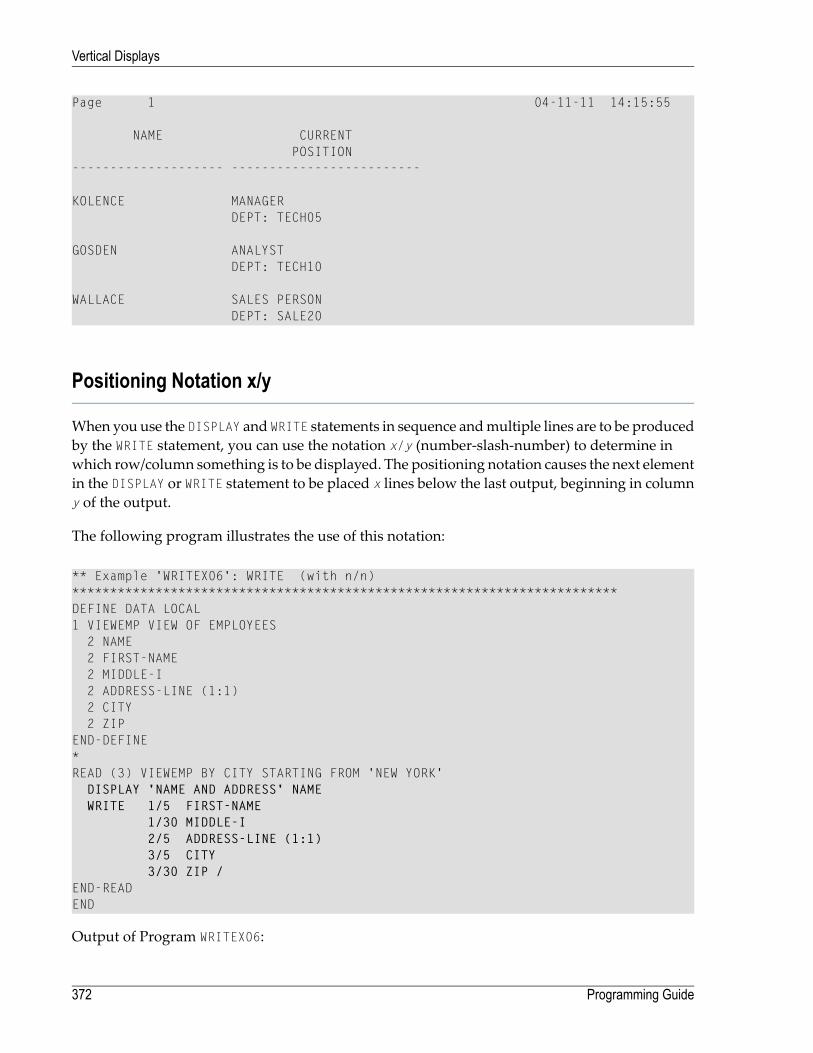
Page 1 04-11-11 14:15:55
NAME CURRENTPOSITION
-------------------- -------------------------
KOLENCE MANAGERDEPT: TECH05
GOSDEN ANALYSTDEPT: TECH10
WALLACE SALES PERSONDEPT: SALE20
Positioning Notation x/y
When you use the DISPLAY and WRITE statements in sequence andmultiple lines are to be producedby the WRITE statement, you can use the notation x/y (number-slash-number) to determine inwhich row/column something is to be displayed. The positioning notation causes the next elementin the DISPLAY or WRITE statement to be placed x lines below the last output, beginning in columny of the output.
The following program illustrates the use of this notation:
** Example 'WRITEX06': WRITE (with n/n)************************************************************************DEFINE DATA LOCAL1 VIEWEMP VIEW OF EMPLOYEES
2 NAME2 FIRST-NAME2 MIDDLE-I2 ADDRESS-LINE (1:1)2 CITY2 ZIP
END-DEFINE*READ (3) VIEWEMP BY CITY STARTING FROM 'NEW YORK'
DISPLAY 'NAME AND ADDRESS' NAMEWRITE 1/5 FIRST-NAME
1/30 MIDDLE-I2/5 ADDRESS-LINE (1:1)3/5 CITY3/30 ZIP /
END-READEND
Output of Program WRITEX06:
Programming Guide372
Vertical Displays

Page 1 04-11-11 14:15:55
NAME AND ADDRESS--------------------
RUBINSYLVIA L2003 SARAZEN PLACENEW YORK 10036
WALLACEMARY P12248 LAUREL GLADE CNEW YORK 10036
KELLOGGHENRIETTA S1001 JEFF RYAN DR.NEWARK 19711
DISPLAY VERT Statement
The standard display mode in Natural is horizontal.
With the VERT clause option of the DISPLAY statement, you can override the standard display andproduce a vertical field display.
The HORIZ clause option, which can be used in the same DISPLAY statement, re-activates thestandard horizontal display mode.
Columnheadings in verticalmode are controlledwith various forms of the AS clause. The followingexample programs illustrate the use of the DISPLAY VERT statement:
■ DISPLAY VERT without AS Clause■ DISPLAY with VERT AS CAPTIONED and HORIZ Clause■ DISPLAY with VERT AS 'text' Clause■ DISPLAY with VERT AS 'text' CAPTIONED Clause
373Programming Guide
Vertical Displays
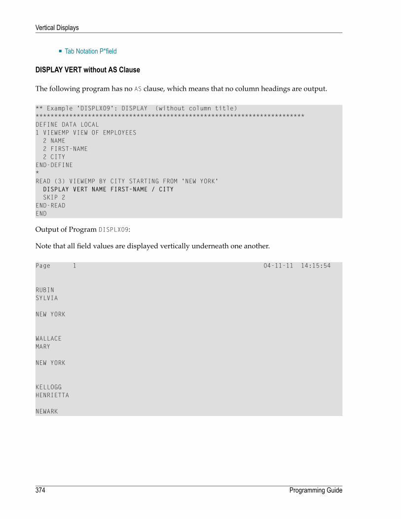
■ Tab Notation P*field
DISPLAY VERT without AS Clause
The following program has no AS clause, which means that no column headings are output.
** Example 'DISPLX09': DISPLAY (without column title)************************************************************************DEFINE DATA LOCAL1 VIEWEMP VIEW OF EMPLOYEES
2 NAME2 FIRST-NAME2 CITY
END-DEFINE*READ (3) VIEWEMP BY CITY STARTING FROM 'NEW YORK'
DISPLAY VERT NAME FIRST-NAME / CITYSKIP 2
END-READEND
Output of Program DISPLX09:
Note that all field values are displayed vertically underneath one another.
Page 1 04-11-11 14:15:54
RUBINSYLVIA
NEW YORK
WALLACEMARY
NEW YORK
KELLOGGHENRIETTA
NEWARK
Programming Guide374
Vertical Displays

DISPLAY with VERT AS CAPTIONED and HORIZ Clause
The following program contains a VERT and a HORIZ clause, which causes some column values tobe output vertically and others horizontally; moreover AS CAPTIONED causes the default columnheaders to be displayed.
** Example 'DISPLX10': DISPLAY (with VERT as CAPTIONED and HORIZ clause)************************************************************************DEFINE DATA LOCAL1 VIEWEMP VIEW OF EMPLOYEES
2 NAME2 FIRST-NAME2 CITY2 JOB-TITLE2 SALARY (1:1)
END-DEFINE*READ (3) VIEWEMP BY CITY STARTING FROM 'NEW YORK'
DISPLAY VERT AS CAPTIONED NAME FIRST-NAMEHORIZ JOB-TITLE SALARY (1:1)
SKIP 1END-READEND
Output of Program DISPLX10:
Page 1 04-11-11 14:15:54
NAME CURRENT ANNUALFIRST-NAME POSITION SALARY
-------------------- ------------------------- ----------
RUBIN SECRETARY 17000SYLVIA
WALLACE ANALYST 38000MARY
KELLOGG DIRECTOR 52000HENRIETTA
375Programming Guide
Vertical Displays

DISPLAY with VERT AS 'text' Clause
The following program contains an AS 'text' clause, which displays the specified 'text' ascolumn header.
Note: A slash (/) within the text element in a DISPLAY statement causes a line advance.
** Example 'DISPLX11': DISPLAY (with VERT AS 'text' clause)************************************************************************DEFINE DATA LOCAL1 VIEWEMP VIEW OF EMPLOYEES
2 NAME2 FIRST-NAME2 CITY2 JOB-TITLE2 SALARY (1:1)
END-DEFINE*READ (3) VIEWEMP BY CITY STARTING FROM 'NEW YORK'
DISPLAY VERT AS 'EMPLOYEES' NAME FIRST-NAMEHORIZ JOB-TITLE SALARY (1:1)
SKIP 1END-READEND
Output of Program DISPLX11:
Page 1 04-11-11 14:15:54
EMPLOYEES CURRENT ANNUALPOSITION SALARY
-------------------- ------------------------- ----------
RUBIN SECRETARY 17000SYLVIA
WALLACE ANALYST 38000MARY
KELLOGG DIRECTOR 52000HENRIETTA
Programming Guide376
Vertical Displays
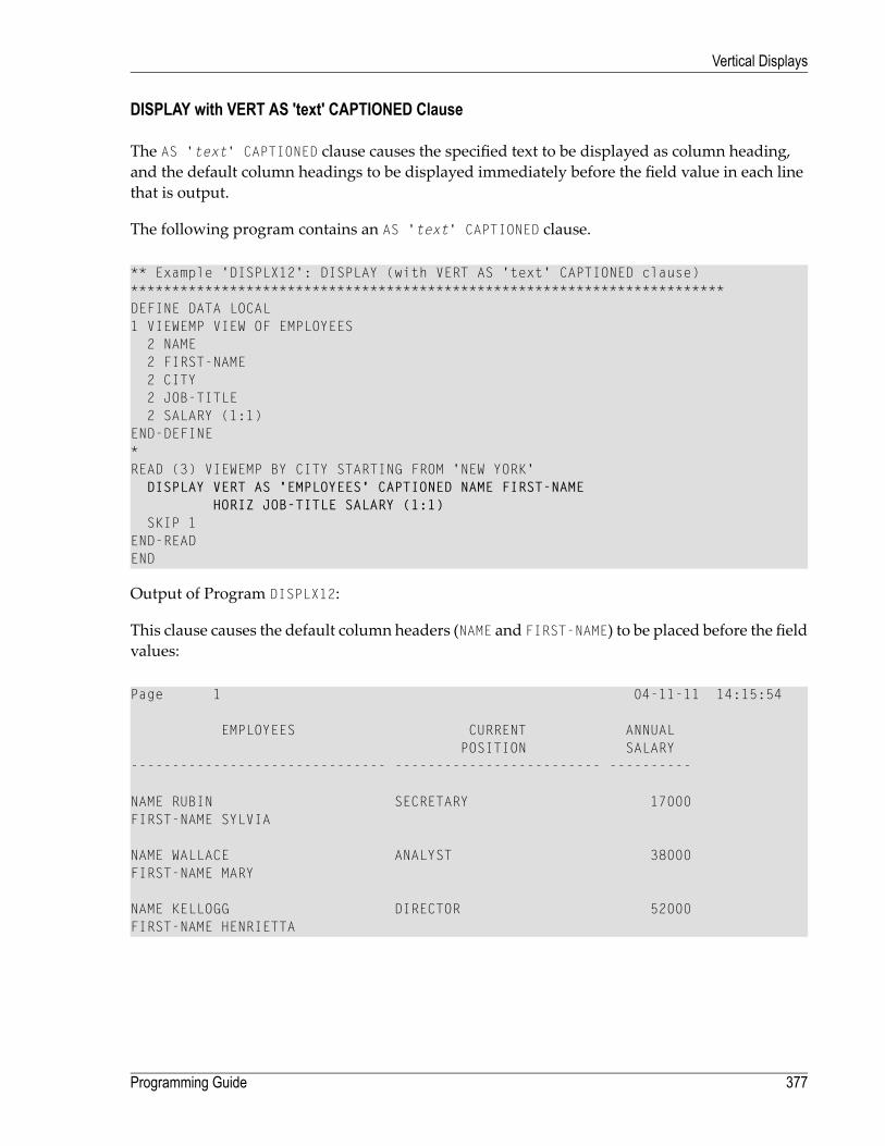
DISPLAY with VERT AS 'text' CAPTIONED Clause
The AS 'text' CAPTIONED clause causes the specified text to be displayed as column heading,and the default column headings to be displayed immediately before the field value in each linethat is output.
The following program contains an AS 'text' CAPTIONED clause.
** Example 'DISPLX12': DISPLAY (with VERT AS 'text' CAPTIONED clause)************************************************************************DEFINE DATA LOCAL1 VIEWEMP VIEW OF EMPLOYEES
2 NAME2 FIRST-NAME2 CITY2 JOB-TITLE2 SALARY (1:1)
END-DEFINE*READ (3) VIEWEMP BY CITY STARTING FROM 'NEW YORK'
DISPLAY VERT AS 'EMPLOYEES' CAPTIONED NAME FIRST-NAMEHORIZ JOB-TITLE SALARY (1:1)
SKIP 1END-READEND
Output of Program DISPLX12:
This clause causes the default column headers (NAME and FIRST-NAME) to be placed before the fieldvalues:
Page 1 04-11-11 14:15:54
EMPLOYEES CURRENT ANNUALPOSITION SALARY
------------------------------- ------------------------- ----------
NAME RUBIN SECRETARY 17000FIRST-NAME SYLVIA
NAME WALLACE ANALYST 38000FIRST-NAME MARY
NAME KELLOGG DIRECTOR 52000FIRST-NAME HENRIETTA
377Programming Guide
Vertical Displays

Tab Notation P*field
If you use a combination of DISPLAY VERT statement and subsequent WRITE statement, you canuse the tab notation P*field-name in the WRITE statement to align the position of a field to thecolumn and line position of a particular field specified in the DISPLAY VERT statement.
In the following program, the fields SALARY and BONUS are displayed in the same column, SALARYin every first line, BONUS in every second line. The text ***SALARY PLUS BONUS*** is aligned toSALARY, which means that it is displayed in the same column as SALARY and in the first line,whereas the text (IN US DOLLARS) is aligned to BONUS and therefore displayed in the same columnas BONUS and in the second line.
** Example 'WRITEX07': WRITE (with P*field)************************************************************************DEFINE DATA LOCAL1 VIEWEMP VIEW OF EMPLOYEES
2 CITY2 NAME2 JOB-TITLE2 SALARY (1:1)2 BONUS (1:1,1:1)
END-DEFINE*READ (3) VIEWEMP BY CITY STARTING FROM 'LOS ANGELES'
DISPLAY NAME JOB-TITLEVERT AS 'INCOME' SALARY (1) BONUS (1,1)
WRITE P*SALARY '***SALARY PLUS BONUS***'P*BONUS '(IN US DOLLARS)'
SKIP 1END-READEND
Output of Program WRITEX07:
Page 1 04-11-11 14:15:55
NAME CURRENT INCOMEPOSITION
-------------------- ------------------------- ----------
SMITH 00
***SALARY PLUS BONUS***(IN US DOLLARS)
POORE JR SECRETARY 250000
***SALARY PLUS BONUS***(IN US DOLLARS)
Programming Guide378
Vertical Displays

PREPARATA MANAGER 460009000
***SALARY PLUS BONUS***(IN US DOLLARS)
Further Example of DISPLAY VERT with WRITE Statement
See the following example program:
■ WRITEX10 - WRITE (with nT, T*field and P*field)
379Programming Guide
Vertical Displays

380
VII Further Programming Aspects
End of Statement, Program or Application
Processing of Application Errors
Conditional Processing - IF Statement
Loop Processing
Control Breaks
Data Computation
System Variables and System Functions
Stack
Processing of Date Information
Text Notation
User Comments
Logical Condition Criteria
Rules for Arithmetic Assignment
Invoking Natural Subprograms from 3GL Programs
Issuing Operating System Commands from within a Natural Program
Statements for Internet and XML Access
381

382
38 End of Statement, Program or Application
■ End of Statement ........................................................................................................................... 384■ End of Program ............................................................................................................................. 384■ End of Application .......................................................................................................................... 384
383

End of Statement
To explicitly mark the end of a statement, you can place a semicolon (;) between the statementand the next statement. This can be used tomake the program structure clearer, but is not required.
End of Program
The END statement is used to mark the end of a Natural program, function, subprogram, externalsubroutine or helproutine.
Every one of these objects must contain an END statement as the last statement.
Every object may contain only one END statement.
End of Application
Ending the Execution of an Application by a STOP Statement
The STOP statement is used to terminate the execution of a Natural application. A STOP statementexecuted anywherewithin an application immediately stops the execution of the entire application.
Ending the Execution of an Application by a TERMINATE Statement
The TERMINATE statement stops the execution of the Natural application and also ends the Naturalsession.
Interrupting a Running Natural Application
During the development of a Natural application and in test situations, the user should be able tointerrupt a running Natural application that does not respond anymore, for example, due to anendless loop. As the Natural session should not need to be killed, the running Natural applicationcan be interrupted via the typical system interrupt key combination (for example, CTRL+BREAK forWindows, CTRL+C for UNIX andOpenVMS). The Natural error NAT1016 is raised and the runtimeerror processing is activated. The error can be handled by an ON ERROR processing.
In a production environment, this featurewill typically need to be disabled, because the applicationmay not be able to recover from a user interrupt at an arbitrary program location.
TheNatural profile parameter RTINTdetermineswhether interrupts are allowed. By default, inter-rupts are not allowed.
Programming Guide384
End of Statement, Program or Application

If this parameter is set to ON, a running Natural application may be interrupted with the interruptkey combination of the operating system (for example, forWindows: CTRL+BREAK; forUNIX: typicallyCTRL+C, but can be reconfigured using the stty command; for OpenVMS: CTRL+C).
Natural catches this interrupt request and then offers the user the following possibilities:
■ Perform standard error processing by raising a NAT1016 error.■ Continue application processing (cancel interrupt).
The choice is shown in a window that is opened after catching the interrupt signal.
Note: TheNatural applicationwill only be interruptible if theNatural application orNaturalStudio that started the application has the input focus.
385Programming Guide
End of Statement, Program or Application

386

39 Processing of Application Errors
■ Natural's Default Error Processing ..................................................................................................... 388■ Application Specific Error Processing ................................................................................................. 388■ Using an ON ERROR Statement Block .............................................................................................. 389■ Using an Error Transaction Program .................................................................................................. 390■ Error Processing Related Features .................................................................................................... 393
387
This section discusses the two basic methods Natural offers for the handling of application errors:default processing and application-specific processing. Furthermore, it describes the options youhave to enable the application specific error processing: coding an ON ERROR statement blockwithin a programming object or using a separate error transaction program.
Finally, this section gives an overview of the features that are provided to configureNatural's errorprocessing behavior, to retrieve information on an error, to process or debug an application error.
This document covers the following topics:
For information on error handling in a Natural RPC environment, see Handling Errors in the Nat-ural Remote Procedure Call documentation.
Natural's Default Error Processing
When an error occurs in a Natural application, Natural will by default proceed in the followingway:
1. Natural terminates the execution of the currently running application object;
2. Natural issues an error message;
3. Natural returns to command input mode.
“Command inputmode”means that, depending on yourNatural configuration, theNatural mainmenu, the NEXT command prompt, or a user-defined startup menu may appear.
The displayed error message contains the Natural error number, the corresponding message textand the affected Natural object and line number where the error has occurred.
Because after the occurrence of an error the execution of the affected application object is terminated,the status of any pending database transactions may be affected by actions required by the settingof the profile parameter ETEOP. Unless Natural has issued an END TRANSACTION statement as aresult of the settings of these parameters, a BACKOUT TRANSACTION statement is issued when Nat-ural returns to command input mode.
Application Specific Error Processing
Natural enables you to adapt the error processing if the default error processing does not meetyour application’s requirements. Possible reasons to establish an application specific error processingmay be:
■ The information on the error is to be stored for further analysis by the application developer.■ The application execution is to be continued after error recovery, if possible.
Programming Guide388
Processing of Application Errors

■ A specific transaction handling is necessary.
Because the execution of the affected Natural application object is terminated after an applicationerror has occurred, the status of the pending database transactions may be influenced by actionswhich are triggered by the settings of the profile parameter ETEOP. Therefore, further transactionhandling (END TRANSACTION or BACKOUT TRANSACTION statement) has to be performed by the ap-plication’s error processing.
To enable the application specific error processing, you have the following options:
■ You may code an ON ERROR statement block within a programming object.■ You may use a separate error transaction program.
These options are described in the following sections.
Using an ON ERROR Statement Block
You may use the ON ERROR statement to intercept execution time errors within the applicationwhere an error occurs.
From within an ON ERROR statement block, it is possible to resume application execution on thecurrent level or on a superior level.
Moreover, you may specify an ON ERROR statement in multiple objects of an application in orderto process any errors that have occurred on subordinate levels. Thus, application specific errorprocessing may exactly be tailored to the application’s needs.
Exiting from an ON ERROR Statement Block
You may exit from an ON ERROR statement block by specifying one of the following statements:
■ RETRY
Application execution is resumed on the current level.■ ESCAPE ROUTINE
Error processing is assumed to be complete and application execution is resumed on the super-ior level.
■ FETCH
Error processing is assumed to be complete and the “fetched” program is executed.
STOP
389Programming Guide
Processing of Application Errors

Natural stops the execution of the affectedprogram, ends the application and returns to commandinput mode.
■ TERMINATE
The execution of the Natural application is stopped and also the Natural session is terminated.
Error Processing Rules
■ If the execution of the ON ERROR statement block is not terminated by one of these statements,the error is percolated to the Natural object on the superior level for processing by an ON ERRORstatement block that exists there.
■ If none of theNatural objects on any of the superior levels contains an ON ERROR statement block,but if an error transaction program has been specified (as described in the next section), thiserror transaction program will receive control.
■ If none of theNatural objects on any of the superior levels contains an ON ERROR statement blockand no error transaction program has been specified there, Natural's default error processingwill be performed as described above.
Using an Error Transaction Program
You may specify an error transaction program in the following places:
■ In the profile parameter ETA.■ If Natural Security is installed, within the Natural Security library profile; see Components of aLibrary Profile in the Natural Security documentation.
■ Within a Natural object by assigning the name of the programwhich is to receive control in theevent of an error condition as a value to the systemvariable *ERROR-TA, using an ASSIGN, COMPUTEor MOVE statement.
If you assign the name of an error transaction program to the system variable *ERROR-TA duringthe Natural session, this assignment supersedes an error transaction program specified using theprofile parameter ETA. Regardless of whether you use the ETA profile parameter or assign a valueto the system variable *ERROR-TA, the error transaction program names are not saved and restoredby Natural for different levels of the call hierarchy. Therefore, if you assign a name to the systemvariable *ERROR-TA in a Natural object, the specified programwill be invoked to process any errorthat occurs in the current Natural session after the assignment.
On the one hand, if you specify an error transaction program by using the profile parameter ETA,an error transaction is defined for the complete Natural session without having the need for indi-vidual assignments in Natural objects. On the other hand, the method of assigning a program tothe system variable *ERROR-TA provides more flexibility and, for example, allows you to havedifferent error transaction programs in different application branches.
Programming Guide390
Processing of Application Errors
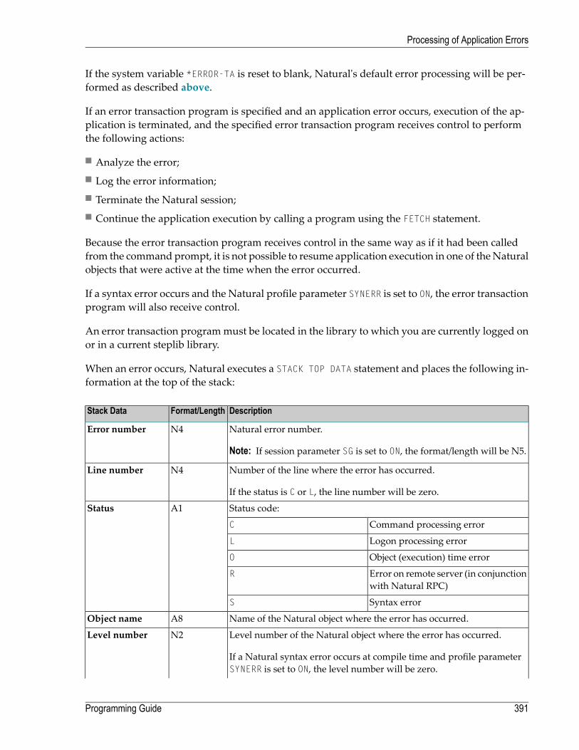
If the system variable *ERROR-TA is reset to blank, Natural's default error processing will be per-formed as described above.
If an error transaction program is specified and an application error occurs, execution of the ap-plication is terminated, and the specified error transaction program receives control to performthe following actions:
■ Analyze the error;■ Log the error information;■ Terminate the Natural session;■ Continue the application execution by calling a program using the FETCH statement.
Because the error transaction program receives control in the same way as if it had been calledfrom the command prompt, it is not possible to resume application execution in one of theNaturalobjects that were active at the time when the error occurred.
If a syntax error occurs and the Natural profile parameter SYNERR is set to ON, the error transactionprogram will also receive control.
An error transaction programmust be located in the library to which you are currently logged onor in a current steplib library.
When an error occurs, Natural executes a STACK TOP DATA statement and places the following in-formation at the top of the stack:
DescriptionFormat/LengthStack Data
Natural error number.
Note: If session parameter SG is set to ON, the format/length will be N5.
N4Error number
Number of the line where the error has occurred.
If the status is C or L, the line number will be zero.
N4Line number
Status code:A1Status
Command processing errorC
Logon processing errorL
Object (execution) time errorO
Error on remote server (in conjunctionwith Natural RPC)
R
Syntax errorS
Name of the Natural object where the error has occurred.A8Object name
Level number of the Natural object where the error has occurred.
If a Natural syntax error occurs at compile time and profile parameterSYNERR is set to ON, the level number will be zero.
N2Level number
391Programming Guide
Processing of Application Errors

DescriptionFormat/LengthStack Data
If a Natural runtime error occurs and the level number of the Naturalobject is greater than 99, the value 99will be stacked, and the currentvalue will be stacked in the additional stack data “Level numberenhanced”.
If a Natural runtime error occurs and the level number of the Natural object is greater than 99:
Current level number (512 at maximum).I4Level numberenhanced
If a Natural syntax error occurs at compile time and profile parameter SYNERR is set to ON:
Position of the offending item in the source line.N3Error position
Length of the offending item.N3Item length
This information can be retrieved in the error transaction program, using an INPUT statement.
Example:
DEFINE DATA LOCAL1 #ERROR-NR (N5)1 #LINE (N4)1 #STATUS-CODE (A1)1 #PROGRAM (A8)1 #LEVEL (N2)1 #LEVELI4 (I4)1 #POSITION-IN-LINE (N3)1 #LENGTH-OF-ITEM (N3)END-DEFINEIF *DATA > 6 THEN /* SYNERR = ON and a syntax error occurred
INPUT#ERROR-NR#LINE#STATUS-CODE#PROGRAM#LEVEL#POSITION-IN-LINE#LENGTH-OF-ITEM
ELSEINPUT /* other error
#ERROR-NR#LINE#STATUS-CODE#PROGRAM#LEVEL#LEVELI4
END-IFWRITE #STATUS-CODE* DECIDE ON FIRST VALUE OF STATUS-CODE* ... /* process error* END-DECIDEEND
Programming Guide392
Processing of Application Errors

Some of the information placed on top of the stack is equivalent to the contents of several systemvariables that are available in an ON ERROR statement block:
Equivalent System Variable in ON ERROR Statement BlockStack Data
*ERROR-NRError number
*ERROR-LINELine number
*PROGRAMObject name
*LEVELLevel number
Rules under Natural Security
If Natural Security is installed, the additional rules for the processing of logon errors apply. Forfurther information, see Transactions in the Natural Security documentation.
Error Processing Related Features
Natural provides a variety of error processing related features that
■ Enable you to configure Natural’s error processing behavior;■ Help you in retrieving information about errors that have occurred;■ Support you in processing these errors;■ Support you in debugging application errors.
These features can be grouped as follows:
■ Profile parameters■ System variables■ Terminal Commands■ System commands■ Application programming interfaces
Profile Parameters
The following profile parameters have an influence on the behavior of Natural in the event of anerror:
393Programming Guide
Processing of Application Errors

PurposeProfile Parameter
Conversion ErrorCPCVERR
Error Transaction ProgramETA
Issue END TRANSACTION at End of ProgramETEOP
Handling of Response Code 113 for FIND StatementRCFIND
Handling of Response Code 113 for GET StatementRCGET
Control of Syntax ErrorsSYNERR
System Variables
The following application related systemvariables can be used to locate an error or to obtain/specifythe name of the program which is to receive control in the event of an error condition:
ContentSystem Variable
Source-code line number of the statement that caused an error.
See Example 1.
*ERROR-LINE
Error number of the error which caused an ON ERROR condition to be entered.*ERROR-NR
Name of the program which is to receive control in the event of an error condition.
See Example 2.
*ERROR-TA
Level number of the Natural object where the error has occurred.*LEVEL
Name of the library to which the user is currently logged on.*LIBRARY-ID
Name of the Natural object that is currently being executed.
See Example 1.
*PROGRAM
Example 1:
.../*ON ERRORIF *ERROR-NR = 3009 THEN
WRITE 'LAST TRANSACTION NOT SUCCESSFUL'/ 'HIT ENTER TO RESTART PROGRAM'
FETCH 'ONEEX1'END-IFWRITE 'ERROR' *ERROR-NR 'OCCURRED IN PROGRAM' *PROGRAM
'AT LINE' *ERROR-LINEFETCH 'MENU'
END-ERROR/*
...
Example 2:
Programming Guide394
Processing of Application Errors
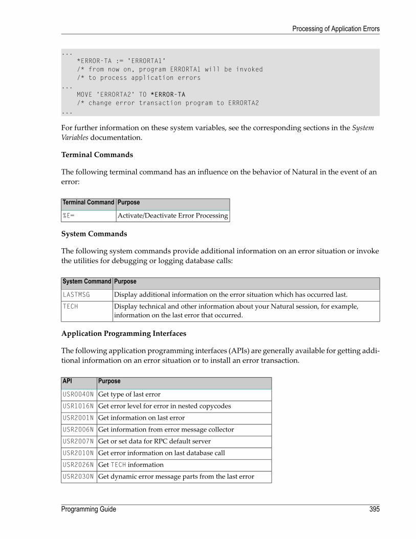
...*ERROR-TA := 'ERRORTA1'/* from now on, program ERRORTA1 will be invoked/* to process application errors
...MOVE 'ERRORTA2' TO *ERROR-TA/* change error transaction program to ERRORTA2
...
For further information on these system variables, see the corresponding sections in the SystemVariables documentation.
Terminal Commands
The following terminal command has an influence on the behavior of Natural in the event of anerror:
PurposeTerminal Command
Activate/Deactivate Error Processing%E=
System Commands
The following system commands provide additional information on an error situation or invokethe utilities for debugging or logging database calls:
PurposeSystem Command
Display additional information on the error situation which has occurred last.LASTMSG
Display technical and other information about your Natural session, for example,information on the last error that occurred.
TECH
Application Programming Interfaces
The following application programming interfaces (APIs) are generally available for getting addi-tional information on an error situation or to install an error transaction.
PurposeAPI
Get type of last errorUSR0040N
Get error level for error in nested copycodesUSR1016N
Get information on last errorUSR2001N
Get information from error message collectorUSR2006N
Get or set data for RPC default serverUSR2007N
Get error information on last database callUSR2010N
Get TECH informationUSR2026N
Get dynamic error message parts from the last errorUSR2030N
395Programming Guide
Processing of Application Errors

PurposeAPI
Find user short error message (including steplibs search)USR3320N
Get program level informationUSR4214N
For further information, see SYSEXT - Natural Application Programming Interfaces in the Utilitiesdocumentation.
Programming Guide396
Processing of Application Errors

40 Conditional Processing - IF Statement
■ Structure of IF Statement ................................................................................................................ 398■ Nested IF Statements ..................................................................................................................... 400
397

With the IF statement, you define a logical condition, and the execution of the statement attachedto the IF statement then depends on that condition.
Structure of IF Statement
The IF statement contains three components:
In the IF clause, you specify the logical condition which is to be met.IF
In the THEN clause you specify the statement(s) to be executed if this condition is met.THEN
In the (optional) ELSE clause, you can specify the statement(s) to be executed if this condition is notmet.
ELSE
So, an IF statement takes the following general form:
IF conditionTHEN execute statement(s)ELSE execute other statement(s)
END-IF
Note: If you wish a certain processing to be performed only if the IF condition is notmet,you can specify the clause THEN IGNORE. The IGNORE statement causes the IF condition tobe ignored if it is met.
Example 1:
** Example 'IFX01': IF************************************************************************DEFINE DATA LOCAL1 MYVIEW VIEW OF EMPLOYEES
2 NAME2 BIRTH2 CITY2 SALARY (1:1)
END-DEFINE*LIMIT 7READ MYVIEW BY CITY STARTING FROM 'C'IF SALARY (1) LT 40000 THEN
WRITE NOTITLE '*****' NAME 30X 'SALARY LT 40000'ELSE
DISPLAY NAME BIRTH (EM=YYYY-MM-DD) SALARY (1)END-IF
END-READEND
Programming Guide398
Conditional Processing - IF Statement

The IF statement block in the above program causes the following conditional processing to beperformed:
■ IF the salary is less than 40000, THEN the WRITE statement is to be executed;■ otherwise (ELSE), that is, if the salary is 40000 or more, the DISPLAY statement is to be executed.
Output of Program IFX01:
NAME DATE ANNUALOF SALARY
BIRTH-------------------- ---------- ----------
***** KEEN SALARY LT 40000***** FORRESTER SALARY LT 40000***** JONES SALARY LT 40000***** MELKANOFF SALARY LT 40000DAVENPORT 1948-12-25 42000GEORGES 1949-10-26 182800***** FULLERTON SALARY LT 40000
Example 2:
** Example 'IFX03': IF************************************************************************DEFINE DATA LOCAL1 EMPLOY-VIEW VIEW OF EMPLOYEES
2 NAME2 CITY2 BONUS (1,1)2 SALARY (1)
*1 #INCOME (N9)1 #TEXT (A26)END-DEFINE*WRITE TITLE '-- DISTRIBUTION OF CATALOGS I AND II --' /*READ (3) EMPLOY-VIEW BY CITY = 'SAN FRANSISCO'
COMPUTE #INCOME = BONUS(1,1) + SALARY(1)/*
IF #INCOME > 40000MOVE 'CATALOGS I AND II' TO #TEXT
ELSEMOVE 'CATALOG I' TO #TEXT
END-IF/*DISPLAY NAME 5X 'SALARY' SALARY(1) / BONUS(1,1)WRITE T*SALARY '-'(10) /
16X 'INCOME:' T*SALARY #INCOME 3X #TEXT /
399Programming Guide
Conditional Processing - IF Statement
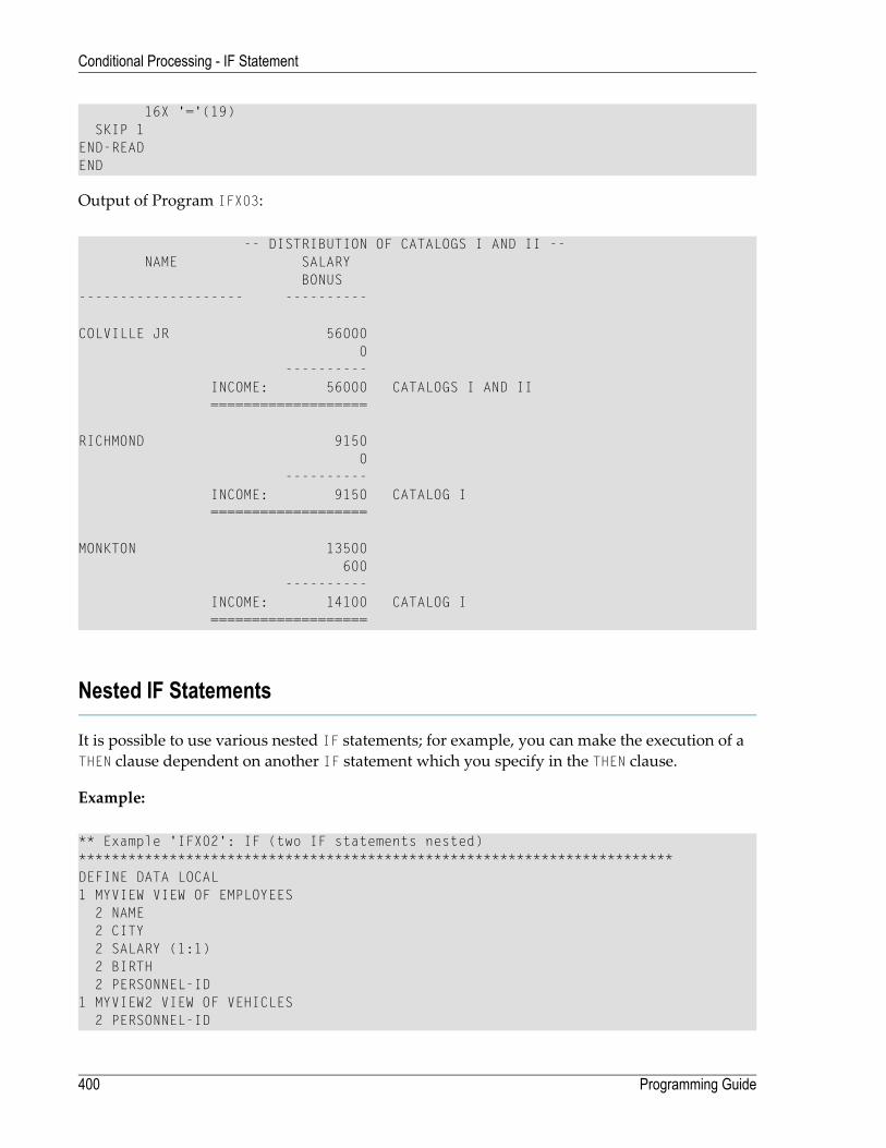
16X '='(19)SKIP 1
END-READEND
Output of Program IFX03:
-- DISTRIBUTION OF CATALOGS I AND II --NAME SALARY
BONUS-------------------- ----------
COLVILLE JR 560000
----------INCOME: 56000 CATALOGS I AND II===================
RICHMOND 91500
----------INCOME: 9150 CATALOG I===================
MONKTON 13500600
----------INCOME: 14100 CATALOG I===================
Nested IF Statements
It is possible to use various nested IF statements; for example, you can make the execution of aTHEN clause dependent on another IF statement which you specify in the THEN clause.
Example:
** Example 'IFX02': IF (two IF statements nested)************************************************************************DEFINE DATA LOCAL1 MYVIEW VIEW OF EMPLOYEES
2 NAME2 CITY2 SALARY (1:1)2 BIRTH2 PERSONNEL-ID
1 MYVIEW2 VIEW OF VEHICLES2 PERSONNEL-ID
Programming Guide400
Conditional Processing - IF Statement

2 MAKE*1 #BIRTH (D)END-DEFINE*MOVE EDITED '19450101' TO #BIRTH (EM=YYYYMMDD)*LIMIT 20FND1. FIND MYVIEW WITH CITY = 'BOSTON'
SORTED BY NAMEIF SALARY (1) LESS THAN 20000
WRITE NOTITLE '*****' NAME 30X 'SALARY LT 20000'ELSE
IF BIRTH GT #BIRTHFIND MYVIEW2 WITH PERSONNEL-ID = PERSONNEL-ID (FND1.)
DISPLAY (IS=ON) NAME BIRTH (EM=YYYY-MM-DD)SALARY (1) MAKE (AL=8 IS=OFF)
END-FINDEND-IF
END-IFSKIP 1
END-FINDEND
Output of Program IFX02:
NAME DATE ANNUAL MAKEOF SALARY
BIRTH-------------------- ---------- ---------- --------
***** COHEN SALARY LT 20000
CREMER 1972-12-14 20000 FORD
***** FLEMING SALARY LT 20000
PERREAULT 1950-05-12 30500 CHRYSLER
***** SHAW SALARY LT 20000
STANWOOD 1946-09-08 31000 CHRYSLERFORD
401Programming Guide
Conditional Processing - IF Statement

402

41 Loop Processing
■ Use of Processing Loops ................................................................................................................ 404■ Limiting Database Loops ................................................................................................................. 404■ Limiting Non-Database Loops - REPEAT Statement ............................................................................. 406■ Example of REPEAT Statement ........................................................................................................ 407■ Terminating a Processing Loop - ESCAPE Statement ........................................................................... 408■ Loops Within Loops ....................................................................................................................... 408■ Example of Nested FIND Statements ................................................................................................. 408■ Referencing Statements within a Program .......................................................................................... 409■ Example of Referencing with Line Numbers ........................................................................................ 411■ Example with Statement Reference Labels ......................................................................................... 412
403

A processing loop is a group of statements which are executed repeatedly until a stated conditionhas been satisfied, or as long as a certain condition prevails.
Use of Processing Loops
Processing loops can be subdivided into database loops and non-database loops:
■ Database processing loopsare those created automatically by Natural to process data selected from a database as a resultof a READ, FIND or HISTOGRAM statement. These statements are described in the sectionDatabaseAccess.
■ Non-database processing loopsare initiated by the statements REPEAT, FOR, CALL FILE, CALL LOOP, SORT, and READ WORK FILE.
More than one processing loopmay be active at the same time. Loopsmay be embedded or nestedwithin other loops which remain active (open).
A processing loopmust be explicitly closedwith a corresponding END-... statement (for example,END-REPEAT, END-FOR)
The SORT statement, which invokes the sort program of the operating system, closes all activeprocessing loops and initiates a new processing loop.
Limiting Database Loops
The following topics are covered below:
■ Possible Ways of Limiting Database Loops■ LT Session Parameter■ LIMIT Statement■ Limit Notation
Programming Guide404
Loop Processing

■ Priority of Limit Settings
Possible Ways of Limiting Database Loops
With the statements READ, FIND or HISTOGRAM, you have three ways of limiting the number of repe-titions of the processing loops initiated with these statements:
■ using the session parameter LT,■ using a LIMIT statement,■ or using a limit notation in a READ/FIND/HISTOGRAM statement itself.
LT Session Parameter
With the system command GLOBALS, you can specify the session parameter LT, which limits thenumber of records which may be read in a database processing loop.
Example:
GLOBALS LT=100
This limit applies to all READ, FIND and HISTOGRAM statements in the entire session.
LIMIT Statement
In a program, you can use the LIMIT statement to limit the number of records which may be readin a database processing loop.
Example:
LIMIT 100
The LIMIT statement applies to the remainder of the program unless it is overridden by anotherLIMIT statement or limit notation.
Limit Notation
With a READ, FIND or HISTOGRAM statement itself, you can specify the number of records to be readin parentheses immediately after the statement name.
405Programming Guide
Loop Processing

Example:
READ (10) VIEWXYZ BY NAME
This limit notation overrides any other limit in effect, but applies only to the statement in whichit is specified.
Priority of Limit Settings
If the limit set with the LT parameter is smaller than a limit specified with a LIMIT statement or alimit notation, the LT limit has priority over any of these other limits.
Limiting Non-Database Loops - REPEAT Statement
Non-database processing loops begin and end based on logical condition criteria or some otherspecified limiting condition.
The REPEAT statement is discussed here as representative of a non-database loop statement.
With the REPEAT statement, you specify one ormore statementswhich are to be executed repeatedly.Moreover, you can specify a logical condition, so that the statements are only executed either untilor as long as that condition is met. For this purpose you use an UNTIL or WHILE clause.
If you specify the logical condition
■ in an UNTIL clause, the REPEAT loop will continue until the logical condition is met;■ in a WHILE clause, the REPEAT loop will continue as long as the logical condition remains true.
If you specify no logical condition, the REPEAT loop must be exited with one of the followingstatements:
■ ESCAPE terminates the execution of the processing loop and continues processing outside theloop (see below).
■ STOP stops the execution of the entire Natural application.■ TERMINATE stops the execution of the Natural application and also ends the Natural session.
Programming Guide406
Loop Processing

Example of REPEAT Statement
** Example 'REPEAX01': REPEAT************************************************************************DEFINE DATA LOCAL1 MYVIEW VIEW OF EMPLOYEES
2 NAME2 SALARY (1:1)
*1 #PAY1 (N8)END-DEFINE*READ (5) MYVIEW BY NAME WHERE SALARY (1) = 30000 THRU 39999
MOVE SALARY (1) TO #PAY1/*REPEAT WHILE #PAY1 LT 40000
MULTIPLY #PAY1 BY 1.1DISPLAY NAME (IS=ON) SALARY (1)(IS=ON) #PAY1
END-REPEAT/*SKIP 1
END-READEND
Output of Program REPEAX01:
Page 1 04-11-11 14:15:54
NAME ANNUAL #PAY1SALARY
-------------------- ---------- ---------
ADKINSON 34500 3795041745
33500 3685040535
36000 3960043560
AFANASSIEV 37000 40700
ALEXANDER 34500 3795041745
407Programming Guide
Loop Processing

Terminating a Processing Loop - ESCAPE Statement
The ESCAPE statement is used to terminate the execution of a processing loop based on a logicalcondition.
You can place an ESCAPE statement within loops in conditional IF statement groups, in breakprocessing statement groups (AT END OF DATA, AT END OF PAGE, AT BREAK), or as a stand-alonestatement implementing the basic logical conditions of a non-database loop.
The ESCAPE statement offers the options TOP and BOTTOM, which determine where processing is tocontinue after the processing loop has been left via the ESCAPE statement:
■ ESCAPE TOP is used to continue processing at the top of the processing loop.■ ESCAPE BOTTOM is used to continue processing with the first statement following the processingloop.
You can specify several ESCAPE statements within the same processing loop.
For further details and examples of the ESCAPE statement, see the Statements documentation.
Loops Within Loops
Adatabase statement can be placedwithin a database processing loop initiated by another databasestatement. When database loop-initiating statements are embedded in this way, a “hierarchy” ofloops is created, each of which is processed for each record which meets the selection criteria.
Multiple levels of loops can be embedded. For example, non-database loops can be nested oneinside the other. Database loops can be nested inside non-database loops. Database and non-database loops can be nested within conditional statement groups.
Example of Nested FIND Statements
The following program illustrates a hierarchy of two loops,with one FIND loop nested or embeddedwithin another FIND loop.
Programming Guide408
Loop Processing

** Example 'FINDX06': FIND (two FIND statements nested)************************************************************************DEFINE DATA LOCAL1 EMPLOY-VIEW VIEW OF EMPLOYEES
2 CITY2 NAME2 PERSONNEL-ID
1 VEH-VIEW VIEW OF VEHICLES2 MAKE2 PERSONNEL-ID
END-DEFINE*FND1. FIND EMPLOY-VIEW WITH CITY = 'NEW YORK' OR = 'BEVERLEY HILLS'
FIND (1) VEH-VIEW WITH PERSONNEL-ID = PERSONNEL-ID (FND1.)DISPLAY NOTITLE NAME CITY MAKE
END-FINDEND-FINDEND
The above program selects data frommultiple files. The outer FIND loop selects from the EMPLOYEESfile all persons who live in New York or Beverley Hills. For each record selected in the outer loop,the inner FIND loop is entered, selecting the car data of those persons from the VEHICLES file.
Output of Program FINDX06:
NAME CITY MAKE
-------------------- -------------------- --------------------
RUBIN NEW YORK FORDOLLE BEVERLEY HILLS GENERAL MOTORSWALLACE NEW YORK MAZDAJONES BEVERLEY HILLS FORDSPEISER BEVERLEY HILLS GENERAL MOTORS
Referencing Statements within a Program
Statement reference notation is used for the following purposes:
■ Referring to previous statements in a program in order to specify processing over a particularrange of data.
■ Overriding Natural's default referencing.■ Documenting.
AnyNatural statement which causes a processing loop to be initiated and/or causes data elementsin a database to be accessed can be referenced, for example:
409Programming Guide
Loop Processing

■ READ
■ FIND
■ HISTOGRAM
■ SORT
■ REPEAT
■ FOR
When multiple processing loops are used in a program, reference notation is used to uniquelyidentify the particular database field to be processed by referring back to the statement that origin-ally accessed that field in the database.
If a field can be referenced in such a way, this is indicated in the Referencing Permitted columnof theOperand Definition Table in the corresponding statement description (in the Statements docu-mentation). See also User-Defined Variables, Referencing of Database Fields Using (r) Notation.
In addition, reference notation can be specified in some statements. For example:
■ AT START OF DATA
■ AT END OF DATA
■ AT BREAK
■ ESCAPE BOTTOM
Without reference notation, an AT START OF DATA, AT END OF DATA or AT BREAK statement willbe related to the outermost active READ, FIND, HISTOGRAM, SORT or READ WORK FILE loop. With refer-ence notation, you can relate it to another active processing loop.
If reference notation is specified with an ESCAPE BOTTOM statement, processing will continue withthe first statement following the processing loop identified by the reference notation.
Statement reference notation may be specified in the form of a statement reference label or a source-code line number.
■ Statement reference labelA statement reference label consists of several characters, the last of which must be a period (.).The period serves to identify the entry as a label.
A statement that is to be referenced is marked with a label by placing the label at the beginningof the line that contains the statement. For example:
Programming Guide410
Loop Processing

0030 ...0040 READ1. READ VIEWXYZ BY NAME0050 ...
In the statement that references the marked statement, the label is placed in parentheses at thelocation indicated in the statement's syntax diagram (as described in the Statements documenta-tion). For example:
AT BREAK (READ1.) OF NAME
■ Source-code line numberIf source-code line numbers are used for referencing, they must be specified as 4-digit numbers(leading zeros must not be omitted) and in parentheses. For example:
AT BREAK (0040) OF NAME
In a statement where the label/line number relates a particular field to a previous statement, thelabel/line number is placed in parentheses after the field name. For example:
DISPLAY NAME (READ1.) JOB-TITLE (READ1.) MAKE MODEL
Line numbers and labels can be used interchangeably.
See also User-Defined Variables, Referencing of Database Fields Using (r) Notation.
Example of Referencing with Line Numbers
The following program uses source code line numbers (4-digit numbers in parentheses) for refer-encing.
In this particular example, the line numbers refer to the statements that would be referenced inany case by default.
0010 ** Example 'LABELX01': Labels for READ and FIND loops (line numbers)0020 ************************************************************************0030 DEFINE DATA LOCAL0040 1 MYVIEW1 VIEW OF EMPLOYEES0050 2 NAME0060 2 FIRST-NAME0070 2 PERSONNEL-ID0080 1 MYVIEW2 VIEW OF VEHICLES0090 2 PERSONNEL-ID0100 2 MAKE0110 END-DEFINE0120 *
411Programming Guide
Loop Processing

0130 LIMIT 150140 READ MYVIEW1 BY NAME STARTING FROM 'JONES'0150 FIND MYVIEW2 WITH PERSONNEL-ID = PERSONNEL-ID (0140)0160 IF NO RECORDS FOUND0170 MOVE '***NO CAR***' TO MAKE0180 END-NOREC0190 DISPLAY NOTITLE NAME (0140) (IS=ON)0200 FIRST-NAME (0140) (IS=ON)0210 MAKE (0150)0220 END-FIND /* (0150)0230 END-READ /* (0140)0240 END
Example with Statement Reference Labels
The following example illustrates the use of statement reference labels.
It is identical to the previous program, except that labels are used for referencing instead of linenumbers.
** Example 'LABELX02': Labels for READ and FIND loops (user labels)************************************************************************DEFINE DATA LOCAL1 MYVIEW1 VIEW OF EMPLOYEES
2 NAME2 FIRST-NAME2 PERSONNEL-ID
1 MYVIEW2 VIEW OF VEHICLES2 PERSONNEL-ID2 MAKE
END-DEFINE*LIMIT 15RD. READ MYVIEW1 BY NAME STARTING FROM 'JONES'
FD. FIND MYVIEW2 WITH PERSONNEL-ID = PERSONNEL-ID (RD.)IF NO RECORDS FOUNDMOVE '***NO CAR***' TO MAKE
END-NORECDISPLAY NOTITLE NAME (RD.) (IS=ON)
FIRST-NAME (RD.) (IS=ON)MAKE (FD.)
END-FIND /* (FD.)END-READ /* (RD.) END ↩
Both programs produce the following output:
Programming Guide412
Loop Processing
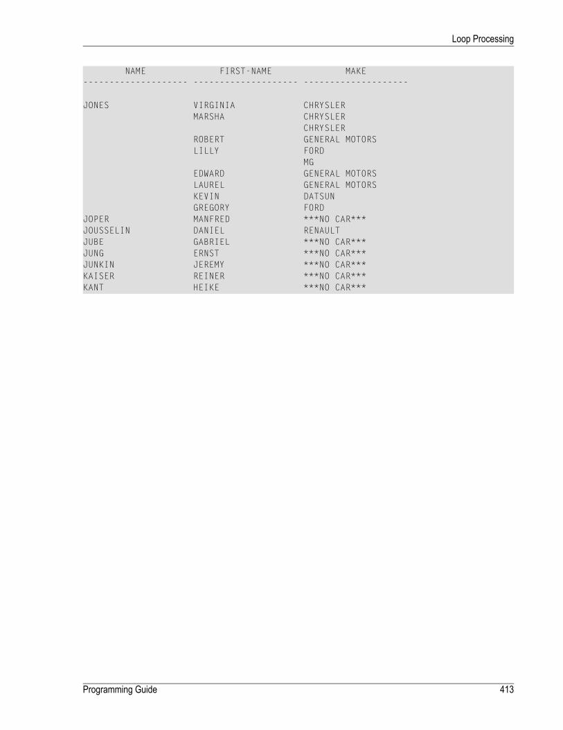
NAME FIRST-NAME MAKE-------------------- -------------------- --------------------
JONES VIRGINIA CHRYSLERMARSHA CHRYSLER
CHRYSLERROBERT GENERAL MOTORSLILLY FORD
MGEDWARD GENERAL MOTORSLAUREL GENERAL MOTORSKEVIN DATSUNGREGORY FORD
JOPER MANFRED ***NO CAR***JOUSSELIN DANIEL RENAULTJUBE GABRIEL ***NO CAR***JUNG ERNST ***NO CAR***JUNKIN JEREMY ***NO CAR***KAISER REINER ***NO CAR***KANT HEIKE ***NO CAR***
413Programming Guide
Loop Processing

414

42 Control Breaks
■ Use of Control Breaks ..................................................................................................................... 416■ AT BREAK Statement ..................................................................................................................... 416■ Automatic Break Processing ............................................................................................................ 421■ Example of System Functions with AT BREAK Statement ...................................................................... 422■ Further Example of AT BREAK Statement .......................................................................................... 424■ BEFORE BREAK PROCESSING Statement ....................................................................................... 424■ Example of BEFORE BREAK PROCESSING Statement ....................................................................... 424■ User-Initiated Break Processing - PERFORM BREAK PROCESSING Statement ........................................ 425■ Example of PERFORM BREAK PROCESSING Statement ..................................................................... 427
415

This chapter describes how the execution of a statement can bemade dependent on a control break,and how control breaks can be used for the evaluation of Natural system functions.
Use of Control Breaks
A control break occurs when the value of a control field changes.
The execution of statements can be made dependent on a control break.
A control break can also be used for the evaluation of Natural system functions.
System functions are discussed in SystemVariables and SystemFunctions. For detailed descriptionsof the system functions available, refer to the System Functions documentation.
AT BREAK Statement
With the statement AT BREAK, you specify the processing which is to be performed whenever acontrol break occurs, that is, whenever the value of a control field which you specify with the ATBREAK statement changes. As a control field, you can use a database field or a user-defined variable.
The following topics are covered below:
■ Control Break Based on a Database Field■ Control Break Based on a User-Defined Variable■ Multiple Control Break Levels
Control Break Based on a Database Field
The field specified as control field in an AT BREAK statement is usually a database field.
Example:
...AT BREAK OF DEPT
statementsEND-BREAK...
In this example, the control field is the database field DEPT; if the value of the field changes, forexample, FROM SALE01 to SALE02, the statements specified in the AT BREAK statement would beexecuted.
Programming Guide416
Control Breaks

Instead of an entire field, you can also use only part of a field as a control field.With the slash-n-slashnotation /n/, you can determine that only the first n positions of a field are to be checked for achange in value.
Example:
...AT BREAK OF DEPT /4/
statementsEND-BREAK...
In this example, the specified statementswould only be executed if the value of the first 4 positionsof the field DEPT changes, for example, FROM SALE to TECH; if, however, the field value changesfrom SALE01 to SALE02, this would be ignored and no AT BREAK processing performed.
Example:
** Example 'ATBREX01': AT BREAK OF (with database field)************************************************************************DEFINE DATA LOCAL1 MYVIEW VIEW OF EMPLOYEES
2 NAME2 CITY2 COUNTRY2 JOB-TITLE2 SALARY (1:1)
END-DEFINE*READ (5) MYVIEW BY CITY WHERE COUNTRY = 'USA'
DISPLAY CITY (AL=9) NAME 'POSITION' JOB-TITLE 'SALARY' SALARY(1)/*AT BREAK OF CITY
WRITE / OLD(CITY) (EM=X^X^X^X^X^X^X^X^X^X^X^)5X 'AVERAGE:' T*SALARY AVER(SALARY(1)) //
COUNT(SALARY(1)) 'RECORDS FOUND' /END-BREAK/*AT END OF DATA
WRITE 'TOTAL (ALL RECORDS):' T*SALARY(1) TOTAL(SALARY(1))END-ENDDATA
END-READEND
In the above program, the first WRITE statement is executed whenever the value of the field CITYchanges.
In the AT BREAK statement, the Natural system functions OLD, AVER and COUNT are evaluated (andoutput in the WRITE statement).
417Programming Guide
Control Breaks

In the AT END OF DATA statement, the Natural system function TOTAL is evaluated.
Output of Program ATBREX01:
Page 1 04-12-14 14:07:26 CITY NAME POSITION SALARY --------- -------------------- ------------------------- ---------- AIKEN SENKO PROGRAMMER 31500 A I K E N AVERAGE: 31500 1 RECORDS FOUND ALBUQUERQ HAMMOND SECRETARY 22000 ALBUQUERQ ROLLING MANAGER 34000 ALBUQUERQ FREEMAN MANAGER 34000 ALBUQUERQ LINCOLN ANALYST 41000 A L B U Q U E R Q U E AVERAGE: 32750 4 RECORDS FOUND TOTAL (ALL RECORDS): 162500 ↩
Control Break Based on a User-Defined Variable
A user-defined variable can also be used as control field in an AT BREAK statement.
In the following program, the user-defined variable #LOCATION is used as control field.
** Example 'ATBREX02': AT BREAK OF (with user-defined variable and** in conjunction with BEFORE BREAK PROCESSING)************************************************************************DEFINE DATA LOCAL1 MYVIEW VIEW OF EMPLOYEES
2 CITY2 COUNTRY2 JOB-TITLE2 SALARY (1:1)
*1 #LOCATION (A20)END-DEFINE*READ (5) MYVIEW BY CITY WHERE COUNTRY = 'USA'
BEFORE BREAK PROCESSINGCOMPRESS CITY 'USA' INTO #LOCATION
END-BEFOREDISPLAY #LOCATION 'POSITION' JOB-TITLE 'SALARY' SALARY (1)
Programming Guide418
Control Breaks

/*AT BREAK OF #LOCATION
SKIP 1END-BREAK
END-READEND
Output of Program ATBREX02:
Page 1 04-12-14 14:08:36 #LOCATION POSITION SALARY -------------------- ------------------------- ---------- AIKEN USA PROGRAMMER 31500 ALBUQUERQUE USA SECRETARY 22000 ALBUQUERQUE USA MANAGER 34000 ALBUQUERQUE USA MANAGER 34000 ALBUQUERQUE USA ANALYST 41000 ↩
Multiple Control Break Levels
As explained above, the notation /n/ allows some portion of a field to be checked for a controlbreak. It is possible to combine several AT BREAK statements, using an entire field as control fieldfor one break and part of the same field as control field for another break.
In such a case, the break at the lower level (entire field) must be specified before the break at thehigher level (part of field); that is, in the first AT BREAK statement the entire field must be specifiedas control field, and in the second one part of the field.
The following example program illustrates this, using the field DEPT as well as the first 4 positionsof that field (DEPT /4/).
** Example 'ATBREX03': AT BREAK OF (two statements in combination)************************************************************************DEFINE DATA LOCAL1 MYVIEW VIEW OF EMPLOYEES
2 NAME2 JOB-TITLE2 DEPT2 SALARY (1:1)2 CURR-CODE (1:1)
END-DEFINE*READ MYVIEW BY DEPT STARTING FROM 'SALE40' ENDING AT 'TECH10'
WHERE SALARY(1) GT 47000 AND CURR-CODE(1) = 'USD'/*AT BREAK OF DEPT
WRITE '*** LOWEST BREAK LEVEL ***' /
419Programming Guide
Control Breaks

END-BREAKAT BREAK OF DEPT /4/
WRITE '*** HIGHEST BREAK LEVEL ***'END-BREAK/*DISPLAY DEPT NAME 'POSITION' JOB-TITLE
END-READEND
Output of Program ATBREX03:
Page 1 04-12-14 14:09:20 DEPARTMENT NAME POSITION CODE ---------- -------------------- ------------------------- TECH05 HERZOG MANAGER TECH05 LAWLER MANAGER TECH05 MEYER MANAGER *** LOWEST BREAK LEVEL *** TECH10 DEKKER DBA *** LOWEST BREAK LEVEL *** *** HIGHEST BREAK LEVEL *** ↩
In the following program, one blank line is output whenever the value of the field DEPT changes;and whenever the value in the first 4 positions of DEPT changes, a record count is carried out byevaluating the system function COUNT.
** Example 'ATBREX04': AT BREAK OF (two statements in combination)************************************************************************DEFINE DATA LOCAL1 MYVIEW VIEW OF EMPLOYEES
2 DEPT2 REDEFINE DEPT
3 #GENDEP (A4)2 NAME2 SALARY (1)
END-DEFINE*WRITE TITLE '** PERSONS WITH SALARY > 30000, SORTED BY DEPARTMENT **' /LIMIT 9READ MYVIEW BY DEPT FROM 'A' WHERE SALARY(1) > 30000
DISPLAY 'DEPT' DEPT NAME 'SALARY' SALARY(1)/*AT BREAK OF DEPT
SKIP 1END-BREAKAT BREAK OF DEPT /4/
Programming Guide420
Control Breaks

WRITE COUNT(SALARY(1)) 'RECORDS FOUND IN:' OLD(#GENDEP) /END-BREAK
END-READEND
Output of Program ATBREX04:
** PERSONS WITH SALARY > 30000, SORTED BY DEPARTMENT ** DEPT NAME SALARY ------ -------------------- ---------- ADMA01 JENSEN 180000 ADMA01 PETERSEN 105000 ADMA01 MORTENSEN 320000 ADMA01 MADSEN 149000 ADMA01 BUHL 642000 ADMA02 HERMANSEN 391500 ADMA02 PLOUG 162900 ADMA02 HANSEN 234000 8 RECORDS FOUND IN: ADMA COMP01 HEURTEBISE 168800 1 RECORDS FOUND IN: COMP ↩
Automatic Break Processing
Automatic break processing is in effect for a processing loopwhich contains an AT BREAK statement.This applies to the following statements:
■ FIND
■ READ
■ HISTOGRAM
■ SORT
■ READ WORK FILE
The value of the control field specified with the AT BREAK statement is checked only for recordswhich satisfy the selection criteria of both the WITH clause and the WHERE clause.
Natural system functions (AVER, MAX, MIN, etc.) are evaluated for each record after all statementswithin the processing loop have been executed. System functions are not evaluated for any recordwhich is rejected by WHERE criteria.
421Programming Guide
Control Breaks
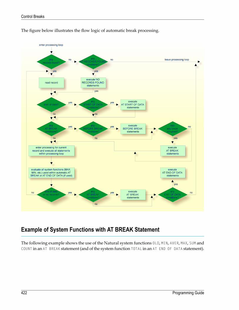
The figure below illustrates the flow logic of automatic break processing.
Example of System Functions with AT BREAK Statement
The following example shows the use of the Natural system functions OLD, MIN, AVER, MAX, SUM andCOUNT in an AT BREAK statement (and of the system function TOTAL in an AT END OF DATA statement).
Programming Guide422
Control Breaks

** Example 'ATBREX05': AT BREAK OF (with system functions)************************************************************************DEFINE DATA LOCAL1 MYVIEW VIEW OF EMPLOYEES
2 NAME2 CITY2 SALARY (1:1)2 CURR-CODE (1:1)
END-DEFINE*LIMIT 3READ MYVIEW BY CITY = 'SALT LAKE CITY'
DISPLAY NOTITLE CITY NAME 'SALARY' SALARY(1) 'CURRENCY' CURR-CODE(1)/*AT BREAK OF CITY
WRITE / OLD(CITY) (EM=X^X^X^X^X^X^X^X^X^X^X^X^X^X^X)31T ' - MINIMUM:' MIN(SALARY(1)) CURR-CODE(1) /31T ' - AVERAGE:' AVER(SALARY(1)) CURR-CODE(1) /31T ' - MAXIMUM:' MAX(SALARY(1)) CURR-CODE(1) /31T ' - SUM:' SUM(SALARY(1)) CURR-CODE(1) /33T COUNT(SALARY(1)) 'RECORDS FOUND' /
END-BREAK/*AT END OF DATA
WRITE 22T 'TOTAL (ALL RECORDS):'T*SALARY TOTAL(SALARY(1)) CURR-CODE(1)
END-ENDDATAEND-READEND
Output of Program ATBREX05:
CITY NAME SALARY CURRENCY-------------------- -------------------- ---------- -------- SALT LAKE CITY ANDERSON 50000 USD SALT LAKE CITY SAMUELSON 24000 USD S A L T L A K E C I T Y - MINIMUM: 24000 USD - AVERAGE: 37000 USD - MAXIMUM: 50000 USD - SUM: 74000 USD 2 RECORDS FOUND SAN DIEGO GEE 60000 USD S A N D I E G O - MINIMUM: 60000 USD - AVERAGE: 60000 USD - MAXIMUM: 60000 USD - SUM: 60000 USD 1 RECORDS FOUND
423Programming Guide
Control Breaks

TOTAL (ALL RECORDS): 134000 USD ↩
Further Example of AT BREAK Statement
See the following example program:
■ ATBREX06 - AT BREAKOF (comparing NMIN, NAVER, NCOUNTwithMIN, AVER, COUNT)
BEFORE BREAK PROCESSING Statement
With the BEFORE BREAK PROCESSING statement, you can specify statements that are to be executedimmediately before a control break; that is, before the value of the control field is checked, beforethe statements specified in the AT BREAK block are executed, and before any Natural system func-tions are evaluated.
Example of BEFORE BREAK PROCESSING Statement
** Example 'BEFORX01': BEFORE BREAK PROCESSING************************************************************************DEFINE DATA LOCAL1 MYVIEW VIEW OF EMPLOYEES
2 NAME2 FIRST-NAME2 SALARY (1:1)2 BONUS (1:1,1:1)
*1 #INCOME (P11)END-DEFINE*LIMIT 5READ MYVIEW BY NAME FROM 'B'BEFORE BREAK PROCESSING
COMPUTE #INCOME = SALARY(1) + BONUS(1,1)END-BEFORE/*DISPLAY NOTITLE NAME FIRST-NAME (AL=10)
'ANNUAL/INCOME' #INCOME 'SALARY' SALARY(1) (LC==) /'+ BONUS' BONUS(1,1) (IC=+)
AT BREAK OF #INCOMEWRITE T*#INCOME '-'(24)
END-BREAK
Programming Guide424
Control Breaks

END-READEND
Output of Program BEFORX01:
NAME FIRST-NAME ANNUAL SALARYINCOME + BONUS
-------------------- ---------- ------------ -----------
BACHMANN HANS 56800 = 52800+4000
------------------------BAECKER JOHANNES 81000 = 74400
+6600------------------------
BAECKER KARL 52650 = 48600+4050
------------------------BAGAZJA MARJAN 152700 = 129700
+23000------------------------
BAILLET PATRICK 198500 = 188000+10500
------------------------
User-InitiatedBreak Processing - PERFORMBREAKPROCESSINGStatement
With automatic break processing, the statements specified in an AT BREAK block are executedwhenever the value of the specified control field changes - regardless of the position of the ATBREAK statement in the processing loop.
With a PERFORM BREAK PROCESSING statement, you can perform break processing at a specifiedposition in a processing loop: the PERFORM BREAK PROCESSING statement is executed when it isencountered in the processing flow of the program.
Immediately after the PERFORM BREAK PROCESSING, you specify one or more AT BREAK statementblocks:
...PERFORM BREAK PROCESSING
AT BREAK OF field1statements
END-BREAKAT BREAK OF field2
statementsEND-BREAK
...
425Programming Guide
Control Breaks

When a PERFORM BREAK PROCESSING is executed, Natural checks if a break has occurred; that is,if the value of the specified control field has changed; and if it has, the specified statements areexecuted.
With PERFORM BREAK PROCESSING, system functions are evaluated beforeNatural checks if a breakhas occurred.
The following figure illustrates the flow logic of user-initiated break processing:
Programming Guide426
Control Breaks

Example of PERFORM BREAK PROCESSING Statement
** Example 'PERFBX01': PERFORM BREAK PROCESSING (with BREAK option** in IF statement)************************************************************************DEFINE DATA LOCAL1 MYVIEW VIEW OF EMPLOYEES
2 NAME2 DEPT2 SALARY (1:1)
*1 #CNTL (N2)END-DEFINE*LIMIT 7READ MYVIEW BY DEPT
AT BREAK OF DEPT /* <- automatic break processingSKIP 1WRITE 'SUMMARY FOR ALL SALARIES '
'SUM:' SUM(SALARY(1))'TOTAL:' TOTAL(SALARY(1))
ADD 1 TO #CNTLEND-BREAK/*IF SALARY (1) GREATER THAN 100000 OR BREAK #CNTL
PERFORM BREAK PROCESSING /* <- user-initiated break processingAT BREAK OF #CNTLWRITE 'SUMMARY FOR SALARY GREATER 100000'
'SUM:' SUM(SALARY(1))'TOTAL:' TOTAL(SALARY(1))
END-BREAKEND-IF/*IF SALARY (1) GREATER THAN 150000 OR BREAK #CNTL
PERFORM BREAK PROCESSING /* <- user-initiated break processingAT BREAK OF #CNTLWRITE 'SUMMARY FOR SALARY GREATER 150000'
'SUM:' SUM(SALARY(1))'TOTAL:' TOTAL(SALARY(1))
END-BREAKEND-IFDISPLAY NAME DEPT SALARY(1)
END-READEND
Output of Program PERFBX01:
427Programming Guide
Control Breaks

Page 1 04-12-14 14:13:35 NAME DEPARTMENT ANNUAL CODE SALARY -------------------- ---------- ---------- JENSEN ADMA01 180000 PETERSEN ADMA01 105000 MORTENSEN ADMA01 320000 MADSEN ADMA01 149000 BUHL ADMA01 642000 SUMMARY FOR ALL SALARIES SUM: 1396000 TOTAL: 1396000 SUMMARY FOR SALARY GREATER 100000 SUM: 1396000 TOTAL: 1396000 SUMMARY FOR SALARY GREATER 150000 SUM: 1142000 TOTAL: 1142000 HERMANSEN ADMA02 391500 PLOUG ADMA02 162900 SUMMARY FOR ALL SALARIES SUM: 554400 TOTAL: 1950400 SUMMARY FOR SALARY GREATER 100000 SUM: 554400 TOTAL: 1950400 SUMMARY FOR SALARY GREATER 150000 SUM: 554400 TOTAL: 1696400 ↩
Programming Guide428
Control Breaks
43 Data Computation
■ COMPUTE Statement .................................................................................................................... 430■ Statements MOVE and COMPUTE ................................................................................................... 431■ Statements ADD, SUBTRACT, MULTIPLY and DIVIDE ......................................................................... 432■ Example of MOVE, SUBTRACT and COMPUTE Statements .................................................................. 432■ COMPRESS Statement .................................................................................................................. 433■ Example of COMPRESS and MOVE Statements ................................................................................. 434■ Example of COMPRESS Statement .................................................................................................. 435■ Mathematical Functions .................................................................................................................. 436■ Further Examples of COMPUTE, MOVE and COMPRESS Statements ..................................................... 437
429

This chapter discusses arithmetic statements that are used for computing data:
■ COMPUTE
■ ADD
■ SUBTRACT
■ MULTIPLY
■ DIVIDE
In addition, the following statements are discussed which are used to transfer the value of an op-erand into one or more fields:
■ MOVE
■ COMPRESS
Important: For optimum processing, user-defined variables used in arithmetic statementsshould be defined with format P (packed numeric).
COMPUTE Statement
The COMPUTE statement is used to perform arithmetic operations. The following connecting oper-ators are available:
Exponentiation**
Multiplication*
Division/
Addition+
Subtraction-
Parentheses may be used to indicate logical grouping.( )
Programming Guide430
Data Computation

Example 1:
COMPUTE LEAVE-DUE = LEAVE-DUE * 1.1
In this example, the value of the field LEAVE-DUE is multiplied by 1.1, and the result is placed inthe field LEAVE-DUE.
Example 2:
COMPUTE #A = SQRT (#B)
In this example, the square root of the value of the field #B is evaluated, and the result is assignedto the field #A.
SQRT is a mathematical function supported in the following arithmetic statements:
■ COMPUTE
■ ADD
■ SUBTRACT
■ MULTIPLY
■ DIVIDE
For an overview of mathematical functions, seeMathematical Functions below.
Example 3:
COMPUTE #INCOME = BONUS (1,1) + SALARY (1)
In this example, the first bonus of the current year and the current salary amount are added andassigned to the field #INCOME.
Statements MOVE and COMPUTE
The statements MOVE and COMPUTE can be used to transfer the value of an operand into one or morefields. The operand may be a constant such as a text item or a number, a database field, a user-defined variable, a system variable, or, in certain cases, a system function.
The difference between the two statements is that in the MOVE statement the value to be moved isspecified on the left; in the COMPUTE statement the value to be assigned is specified on the right, asshown in the following examples.
431Programming Guide
Data Computation

Examples:
MOVE NAME TO #LAST-NAMECOMPUTE #LAST-NAME = NAME
Statements ADD, SUBTRACT, MULTIPLY and DIVIDE
The ADD, SUBTRACT, MULTIPLY and DIVIDE statements are used to perform arithmetic operations.
Examples:
ADD +5 -2 -1 GIVING #ASUBTRACT 6 FROM 11 GIVING #BMULTIPLY 3 BY 4 GIVING #CDIVIDE 3 INTO #D GIVING #E
All four statements have a ROUNDED option,which you can use if youwish the result of the operationto be rounded.
For rules on rounding, see Rules for Arithmetic Assignment.
The Statements documentation provides more detailed information on these statements.
Example of MOVE, SUBTRACT and COMPUTE Statements
The following program demonstrates the use of user-defined variables in arithmetic statements.It calculates the ages and wages of three employees and outputs these.
** Example 'COMPUX01': COMPUTE************************************************************************DEFINE DATA LOCAL1 MYVIEW VIEW OF EMPLOYEES
2 NAME2 BIRTH2 JOB-TITLE2 SALARY (1:1)2 BONUS (1:1,1:1)
*1 #DATE (N8)1 REDEFINE #DATE
2 #YEAR (N4)2 #MONTH (N2)2 #DAY (N2)
1 #BIRTH-YEAR (A4)1 REDEFINE #BIRTH-YEAR
Programming Guide432
Data Computation

2 #BIRTH-YEAR-N (N4)1 #AGE (N3)1 #INCOME (P9)END-DEFINE*MOVE *DATN TO #DATE*READ (3) MYVIEW BY NAME STARTING FROM 'JONES'
MOVE EDITED BIRTH (EM=YYYY) TO #BIRTH-YEARSUBTRACT #BIRTH-YEAR-N FROM #YEAR GIVING #AGE/*COMPUTE #INCOME = BONUS (1:1,1:1) + SALARY (1:1)/*DISPLAY NAME 'POSITION' JOB-TITLE #AGE #INCOME
END-READEND
Output of Program COMPUX01:
Page 1 04-11-11 14:15:54
NAME POSITION #AGE #INCOME-------------------- ------------------------- ---- ----------
JONES MANAGER 63 55000JONES DIRECTOR 58 50000JONES PROGRAMMER 48 31000
COMPRESS Statement
The COMPRESS statement is used to transfer (combine) the contents of two or more operands intoa single alphanumeric field.
Leading zeros in a numeric field and trailing blanks in an alphanumeric field are suppressed beforethe field value is moved to the receiving field.
By default, the transferred values are separated fromone another by a single blank in the receivingfield. For other separating possibilities, see the COMPRESS statement option LEAVING NO SPACE (inthe Statements documentation).
433Programming Guide
Data Computation
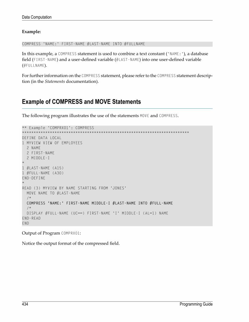
Example:
COMPRESS 'NAME:' FIRST-NAME #LAST-NAME INTO #FULLNAME
In this example, a COMPRESS statement is used to combine a text constant ('NAME:'), a databasefield (FIRST-NAME) and a user-defined variable (#LAST-NAME) into one user-defined variable(#FULLNAME).
For further information on the COMPRESS statement, please refer to the COMPRESS statement descrip-tion (in the Statements documentation).
Example of COMPRESS and MOVE Statements
The following program illustrates the use of the statements MOVE and COMPRESS.
** Example 'COMPRX01': COMPRESS************************************************************************DEFINE DATA LOCAL1 MYVIEW VIEW OF EMPLOYEES
2 NAME2 FIRST-NAME2 MIDDLE-I
*1 #LAST-NAME (A15)1 #FULL-NAME (A30)END-DEFINE*READ (3) MYVIEW BY NAME STARTING FROM 'JONES'
MOVE NAME TO #LAST-NAME/*COMPRESS 'NAME:' FIRST-NAME MIDDLE-I #LAST-NAME INTO #FULL-NAME/*DISPLAY #FULL-NAME (UC==) FIRST-NAME 'I' MIDDLE-I (AL=1) NAME
END-READEND
Output of Program COMPRX01:
Notice the output format of the compressed field.
Programming Guide434
Data Computation

Page 1 04-11-11 14:15:54
#FULL-NAME FIRST-NAME I NAME============================== -------------------- - --------------------
NAME: VIRGINIA J JONES VIRGINIA J JONESNAME: MARSHA JONES MARSHA JONESNAME: ROBERT B JONES ROBERT B JONES
In multiple-line displays, it may be useful to combine fields/text in a user-defined variables byusing a COMPRESS statement.
Example of COMPRESS Statement
In the following program, three user-defined variables are used: #FULL-SALARY, #FULL-NAME, and#FULL-CITY. #FULL-SALARY, for example, contains the text 'SALARY:' and the database fields SALARYand CURR-CODE. The WRITE statement then references only the compressed variables.
** Example 'COMPRX02': COMPRESS************************************************************************DEFINE DATA LOCAL1 VIEWEMP VIEW OF EMPLOYEES
2 NAME2 FIRST-NAME2 SALARY (1:1)2 CURR-CODE (1:1)2 CITY2 ADDRESS-LINE (1:1)2 ZIP
*1 #FULL-SALARY (A25)1 #FULL-NAME (A25)1 #FULL-CITY (A25)END-DEFINE*READ (3) VIEWEMP BY CITY STARTING FROM 'NEW YORK'
COMPRESS 'SALARY:' CURR-CODE(1) SALARY(1) INTO #FULL-SALARYCOMPRESS FIRST-NAME NAME INTO #FULL-NAMECOMPRESS ZIP CITY INTO #FULL-CITY/*DISPLAY 'NAME AND ADDRESS' NAME (EM=X^X^X^X^X^X^X^X^X^X^X^X)WRITE 1/5 #FULL-NAME
1/37 #FULL-SALARY2/5 ADDRESS-LINE (1)3/5 #FULL-CITY
SKIP 1END-READEND
435Programming Guide
Data Computation

Output of Program COMPRX02:
Page 1 04-11-11 14:15:54
NAME AND ADDRESS-----------------------
R U B I NSYLVIA RUBIN SALARY: USD 170002003 SARAZEN PLACE10036 NEW YORK
W A L L A C EMARY WALLACE SALARY: USD 3800012248 LAUREL GLADE C10036 NEW YORK
K E L L O G GHENRIETTA KELLOGG SALARY: USD 520001001 JEFF RYAN DR.19711 NEWARK
Mathematical Functions
The following Natural mathematical functions are supported in arithmetic processing statements(ADD, COMPUTE, DIVIDE, SUBTRACT, MULTIPLY).
Natural System FunctionMathematical Function
ABS(field)Absolute value of field.
ATN(field)Arc tangent of field.
COS(field)Cosine of field.
EXP(field)Exponential of field.
FRAC(field)Fractional part of field.
INT(field)Integer part of field.
LOG(field)Natural logarithm of field.
SGN(field)Sign of field.
SIN(field)Sine of field.
SQRT(field)Square root of field.
TAN(field)Tangent of field.
VAL(field)Numeric value of an alphanumeric field.
See also the System Functions documentation for a detailed explanation of each mathematicalfunction.
Programming Guide436
Data Computation

Further Examples of COMPUTE, MOVE and COMPRESS Statements
See the following example programs:
■ WRITEX11 - WRITE (with nX, n/n and COMPRESS)■ IFX03 - IF statement■ COMPRX03 - COMPRESS (using parameters LC and TC)
437Programming Guide
Data Computation

438

44 System Variables and System Functions
■ System Variables ........................................................................................................................... 440■ System Functions .......................................................................................................................... 441■ Example of System Variables and System Functions ............................................................................ 442■ Further Examples of System Variables ............................................................................................... 443■ Further Examples of System Functions .............................................................................................. 444
439

This chapter describes the purpose of Natural system variables and Natural system functions andhow they are used in Natural programs.
System Variables
The following topics are covered below:
■ Purpose■ Characteristics of System Variables■ System Variables Grouped by Function
Purpose
System variables are used to display system information. They may be referenced at any pointwithin a Natural program.
Natural system variables provide variable information, for example, about the current Naturalsession:
■ the current library;■ the user and terminal identification;■ the current status of a loop processing;■ the current report processing status;■ the current date and time.
The typical use of system variables is illustrated in the Example of System Variables and SystemFunctions below and in the examples contained in library SYSEXPG.
The information contained in a system variable may be used in Natural programs by specifyingthe appropriate system variables. For example, date and time system variables may be specifiedin a DISPLAY, WRITE, PRINT, MOVE or COMPUTE statement.
Characteristics of System Variables
The names of all system variables begin with an asterisk (*).
Format/Length
Information on format and length is given in the detailed descriptions in the System Variablesdocumentation. The following abbreviations are used:
Programming Guide440
System Variables and System Functions

Format
AlphanumericA
BinaryB
DateD
IntegerI
LogicalL
Numeric (unpacked)N
Packed numericP
TimeT
Content Modifiable
In the individual descriptions, this indicateswhether in aNatural programyou can assign anothervalue to the system variable, that is, overwrite its content as generated by Natural.
System Variables Grouped by Function
The Natural system variables are grouped as follows:
■ Application Related System Variables■ Date and Time System Variables■ Input/Ouput Related System Variables■ Natural Environment Related System Variables■ System Environment Related System Variables■ XML Related System Variables
For detailed descriptions of all system variables, see the System Variables documentation.
System Functions
Natural system functions comprise a set of statistical andmathematical functions that can be appliedto the data after a record has been processed, but before break processing occurs.
System functions may be specified in a DISPLAY, WRITE, PRINT, MOVE or COMPUTE statement that isused in conjunction with an AT END OF PAGE, AT END OF DATA or AT BREAK statement.
In the case of an AT END OF PAGE statement, the corresponding DISPLAY statement must includethe GIVE SYSTEM FUNCTIONS clause (as shown in the example below).
The following functional groups of system functions exist:
441Programming Guide
System Variables and System Functions

■ System Functions for Use in Processing Loops■ Mathematical Functions■ Miscellaneous Functions
For detailed information on all system functions available, see the System Functionsdocumentation.
See also Using System Functions in Processing Loops (in the System Functions documentation).
The typical use of system functions is explained in the example programs given below and in theexamples contained in library SYSEXPG.
Example of System Variables and System Functions
The following example program illustrates the use of system variables and system functions:
** Example 'SYSVAX01': System variables and system functions************************************************************************DEFINE DATA LOCAL1 MYVIEW VIEW OF EMPLOYEES
2 CITY2 NAME2 JOB-TITLE2 INCOME (1:1)
3 CURR-CODE3 SALARY3 BONUS (1:1)
END-DEFINE*WRITE TITLE LEFT JUSTIFIED 'EMPLOYEE SALARY REPORT AS OF' *DAT4E /*READ (3) MYVIEW BY CITY STARTING FROM 'E'
DISPLAY GIVE SYSTEM FUNCTIONSNAME (AL=15) JOB-TITLE (AL=15) INCOME (1:1)
AT START OF DATAWRITE 'REPORT CREATED AT:' *TIME 'HOURS' /
END-STARTAT END OF DATA
WRITE / 'LAST PERSON SELECTED:' OLD (NAME) /END-ENDDATA
END-READ*AT END OF PAGE
WRITE 'AVERAGE SALARY:' AVER (SALARY(1))END-ENDPAGEEND
Explanation:
Programming Guide442
System Variables and System Functions

■ The system variable *DATE is output with the WRITE TITLE statement.■ The system variable *TIME is output with the AT START OF DATA statement.■ The system function OLD is used in the AT END OF DATA statement.■ The system function AVER is used in the AT END OF PAGE statement.
Output of Program SYSVAX01:
Note how the system variables and system function are displayed.
EMPLOYEE SALARY REPORT AS OF 11/11/2004
NAME CURRENT INCOMEPOSITION
CURRENCY ANNUAL BONUSCODE SALARY
--------------- --------------- -------- ---------- ----------
REPORT CREATED AT: 14:15:55.0 HOURS
DUYVERMAN PROGRAMMER USD 34000 0PRATT SALES PERSON USD 38000 9000MARKUSH TRAINEE USD 22000 0
LAST PERSON SELECTED: MARKUSH
AVERAGE SALARY: 31333
Further Examples of System Variables
See the following example programs:
■ EDITMX05 - Edit mask (EM for date and time system variables)■ READX04 - READ (in combination with FIND and the system variables *NUMBER and*COUNTER)
■ WTITLX01 - WRITE TITLE (with *PAGE-NUMBER)
443Programming Guide
System Variables and System Functions
Further Examples of System Functions
See the following example programs:
■ ATBREX06 - AT BREAKOF (comparing NMIN, NAVER, NCOUNTwithMIN, AVER, COUNT)■ ATENPX01 -ATENDOFPAGE (with system function available viaGIVESYSTEMFUNCTIONSin DISPLAY)
Programming Guide444
System Variables and System Functions

45 Stack
■ Use of Natural Stack ...................................................................................................................... 446■ Stack Processing ........................................................................................................................... 446■ Placing Data on the Stack ............................................................................................................... 447■ Clearing the Stack ......................................................................................................................... 448
445
The Natural stack is a kind of “intermediate storage” in which you can store Natural commands,user-defined commands, and input data to be used by an INPUT statement.
Use of Natural Stack
In the stack you can store a series of functions which are frequently executed one after the other,such as a series of logon commands.
The data/commands stored in the stack are “stacked” on top of one another. You can decidewhether to put them on top or at the bottom of the stack. The data/command in the stack can onlybe processed in the order in which they are stacked, beginning from the top of the stack.
In a program, you may reference the system variable *DATA to determine the content of the stack(see the System Variables documentation for further information).
Stack Processing
The processing of the commands/data stored in the stack differs depending on the function beingperformed.
If a command is expected, that is, the NEXT prompt is about to be displayed, Natural first checksif a command is on the top of the stack. If there is, the NEXT prompt is suppressed and the commandis read and deleted from the stack; the command is then executed as if it had been enteredmanuallyin response to the NEXT prompt.
If an INPUT statement containing input fields is being executed, Natural first checks if there areany input data on the top of the stack. If there are, these data are passed to the INPUT statement(in delimiter mode); the data read from the stack must be format-compatible with the variables inthe INPUT statement; the data are then deleted from the stack. See also Processing Data from theNatural Stack in the INPUT statement description.
If an INPUT statement was executed using data from the stack, and this INPUT statement is re-ex-ecuted via a REINPUT statement, the INPUT statement screen will be re-executed displaying thesame data from the stack aswhen itwas executed originally.With the REINPUT statement, no furtherdata are read from the stack.
When a Natural program terminates normally, the stack is flushed beginning from the top untileither a command is on the top of the stack or the stack is cleared. When a Natural program isterminated via the terminal command %% or with an error, the stack is cleared entirely.
Programming Guide446
Stack

Placing Data on the Stack
The following methods can be used to place data/commands on the stack:
■ STACK Parameter■ STACK Statement■ FETCH and RUN Statements
STACK Parameter
TheNatural profile parameter STACKmay be used to place data/commands on the stack. The STACKparameter (described in the Parameter Reference) can be specified by the Natural administrator inthe Natural parameter module at the installation of Natural; or you can specify it as a dynamicparameter when you invoke Natural.
When data/commands are to be placed on the stack via the STACK parameter, multiple commandsmust be separated from one another by a semicolon (;). If a command is to be passed within a se-quence of data or command elements, it must be preceded by a semicolon.
Data for multiple INPUT statements must be separated from one another by a colon (:). Data thatare to be read by a separate INPUT statement must be preceded by a colon. If a command is to bestacked which requires parameters, no colon is to be placed between the command and the para-meters.
Semicolon and colonmust not be usedwithin the input data themselves as theywill be interpretedas separation characters.
STACK Statement
The STACK statement can be usedwithin a program to place data/commands in the stack. The dataelements specified in one STACK statement will be used for one INPUT statement, whichmeans thatif data formultiple INPUT statements are to be placed on the stack, multiple STACK statementsmustbe used.
Data may be placed on the stack either unformatted or formatted:
■ If unformatted data are read from the stack, the data string is interpreted in delimiter mode andthe characters specified with the session parameters IA (Input Assignment character) and ID(Input Delimiter character) are processed as control characters for keyword assignment anddata separation.
■ If formatted data are placed on the stack, each content of a field will be separated and passedto one input field in the corresponding INPUT statement. If the data to be placed on the stackcontains delimiter, control or DBCS characters, it should be placed formatted on the stack toavoid unintentional interpretation of these characters.
447Programming Guide
Stack

See the Statements documentation for further information on the STACK statement.
FETCH and RUN Statements
The execution of a FETCH or RUN statement that contains parameters to be passed to the invokedprogram will result in these parameters being placed on top of the stack.
Clearing the Stack
The contents of the stack can be deletedwith the RELEASE statement. See the Statements document-ation for details on the RELEASE statement.
Note: When aNatural program is terminated via the terminal command %% orwith an error,the stack is cleared entirely.
Programming Guide448
Stack
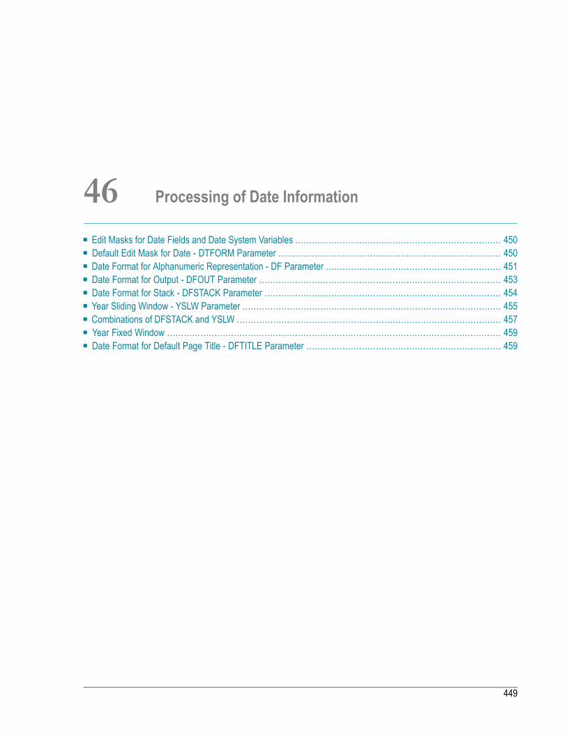
46 Processing of Date Information
■ Edit Masks for Date Fields and Date System Variables .......................................................................... 450■ Default Edit Mask for Date - DTFORM Parameter ................................................................................ 450■ Date Format for Alphanumeric Representation - DF Parameter ............................................................... 451■ Date Format for Output - DFOUT Parameter ....................................................................................... 453■ Date Format for Stack - DFSTACK Parameter ..................................................................................... 454■ Year Sliding Window - YSLW Parameter ............................................................................................. 455■ Combinations of DFSTACK and YSLW ............................................................................................... 457■ Year Fixed Window ........................................................................................................................ 459■ Date Format for Default Page Title - DFTITLE Parameter ...................................................................... 459
449
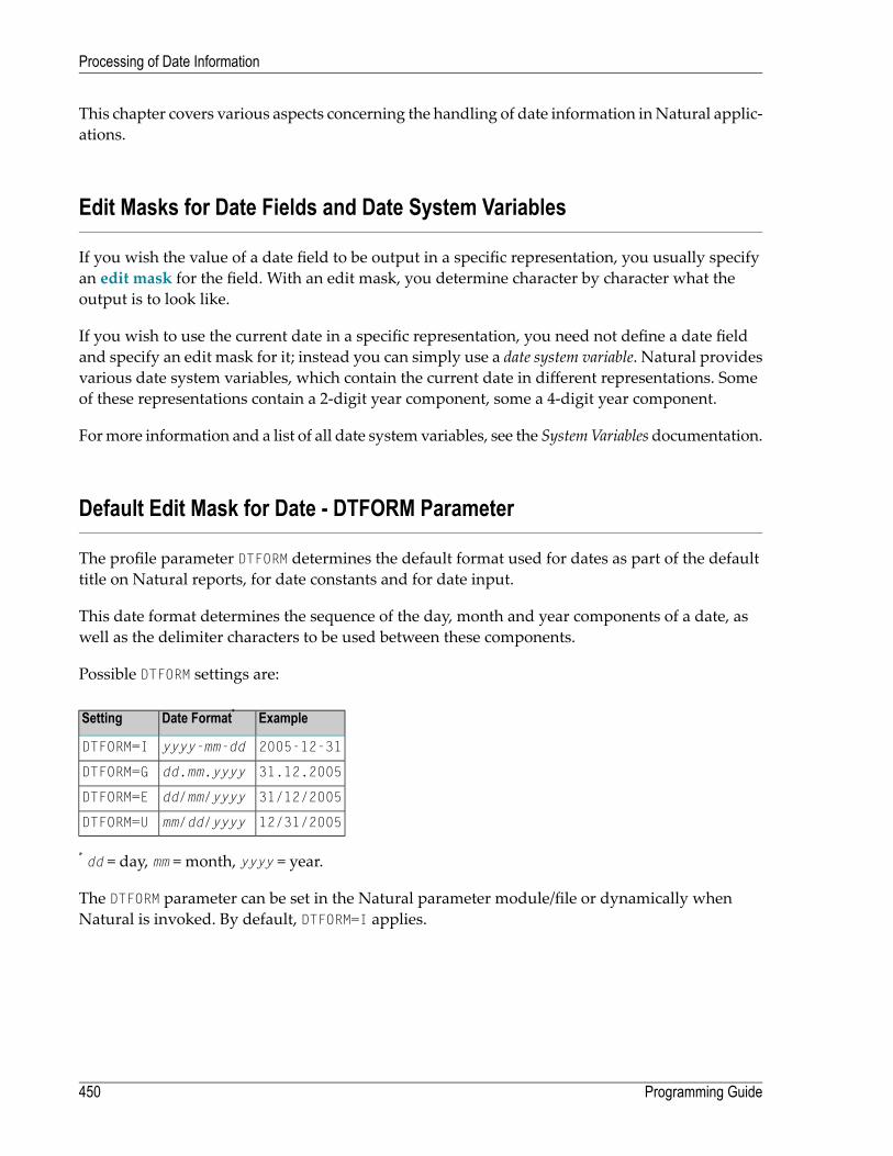
This chapter covers various aspects concerning the handling of date information inNatural applic-ations.
Edit Masks for Date Fields and Date System Variables
If you wish the value of a date field to be output in a specific representation, you usually specifyan edit mask for the field. With an edit mask, you determine character by character what theoutput is to look like.
If you wish to use the current date in a specific representation, you need not define a date fieldand specify an edit mask for it; instead you can simply use a date system variable. Natural providesvarious date system variables, which contain the current date in different representations. Someof these representations contain a 2-digit year component, some a 4-digit year component.
Formore information and a list of all date system variables, see the SystemVariablesdocumentation.
Default Edit Mask for Date - DTFORM Parameter
The profile parameter DTFORM determines the default format used for dates as part of the defaulttitle on Natural reports, for date constants and for date input.
This date format determines the sequence of the day, month and year components of a date, aswell as the delimiter characters to be used between these components.
Possible DTFORM settings are:
ExampleDate Format*Setting
2005-12-31yyyy-mm-ddDTFORM=I
31.12.2005dd.mm.yyyyDTFORM=G
31/12/2005dd/mm/yyyyDTFORM=E
12/31/2005mm/dd/yyyyDTFORM=U
* dd = day, mm = month, yyyy = year.
The DTFORM parameter can be set in the Natural parameter module/file or dynamically whenNatural is invoked. By default, DTFORM=I applies.
Programming Guide450
Processing of Date Information
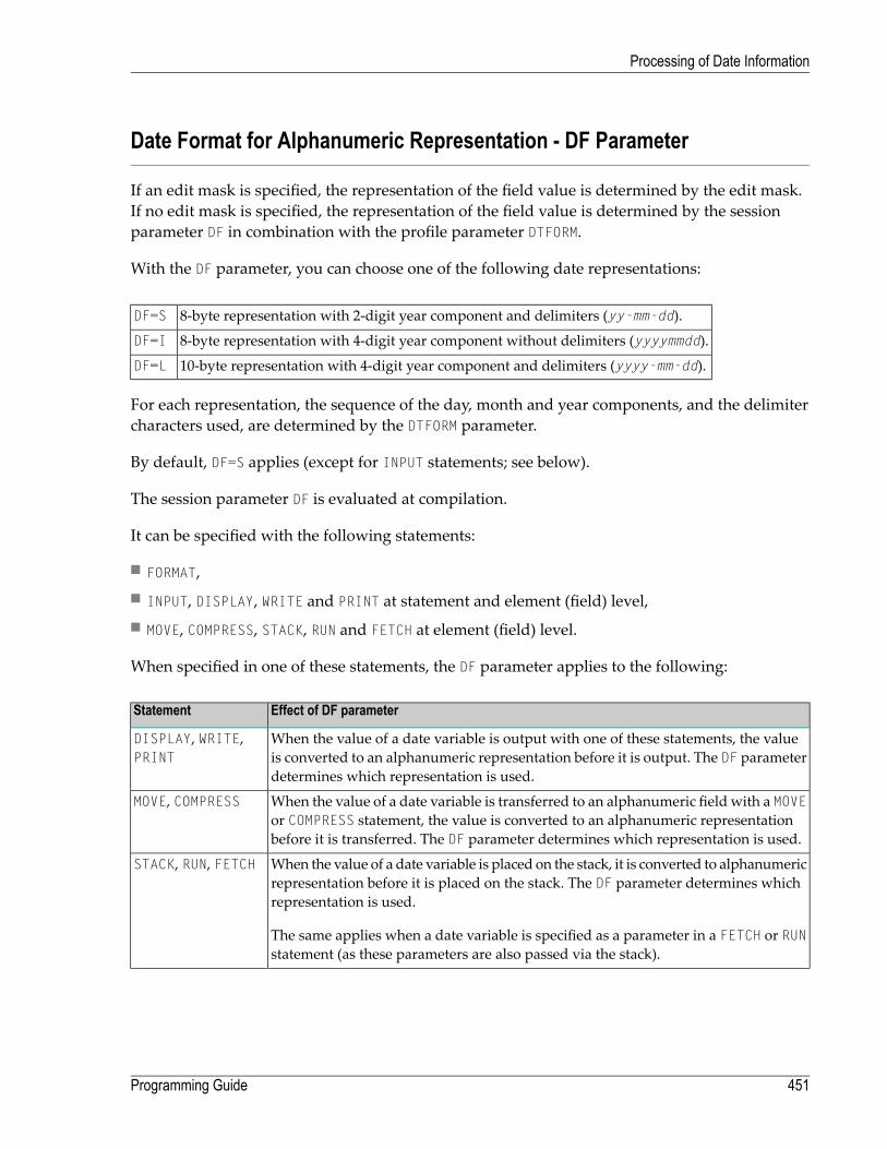
Date Format for Alphanumeric Representation - DF Parameter
If an edit mask is specified, the representation of the field value is determined by the edit mask.If no edit mask is specified, the representation of the field value is determined by the sessionparameter DF in combination with the profile parameter DTFORM.
With the DF parameter, you can choose one of the following date representations:
8-byte representation with 2-digit year component and delimiters (yy-mm-dd).DF=S
8-byte representation with 4-digit year component without delimiters (yyyymmdd).DF=I
10-byte representation with 4-digit year component and delimiters (yyyy-mm-dd).DF=L
For each representation, the sequence of the day, month and year components, and the delimitercharacters used, are determined by the DTFORM parameter.
By default, DF=S applies (except for INPUT statements; see below).
The session parameter DF is evaluated at compilation.
It can be specified with the following statements:
■ FORMAT,■ INPUT, DISPLAY, WRITE and PRINT at statement and element (field) level,■ MOVE, COMPRESS, STACK, RUN and FETCH at element (field) level.
When specified in one of these statements, the DF parameter applies to the following:
Effect of DF parameterStatement
When the value of a date variable is output with one of these statements, the valueis converted to an alphanumeric representation before it is output. The DF parameterdetermines which representation is used.
DISPLAY, WRITE,PRINT
When the value of a date variable is transferred to an alphanumeric field with a MOVEor COMPRESS statement, the value is converted to an alphanumeric representationbefore it is transferred. The DF parameter determines which representation is used.
MOVE, COMPRESS
When the value of a date variable is placed on the stack, it is converted to alphanumericrepresentation before it is placed on the stack. The DF parameter determines whichrepresentation is used.
The same applies when a date variable is specified as a parameter in a FETCH or RUNstatement (as these parameters are also passed via the stack).
STACK, RUN, FETCH
451Programming Guide
Processing of Date Information

Effect of DF parameterStatement
When a data variable is used in an INPUT statement, the DF parameter determineshow a value must be entered in the field.
However, when a date variable for which no DF parameter is specified is used in anINPUT statement, the date can be entered either with a 2-digit year component and
INPUT
delimiters or with a 4-digit year component and no delimiters. In this case, too, thesequence of the day, month and year components, and the delimiter characters to beused, are determined by the DTFORM parameter.
Note: With DF=S, only 2 digits are provided for the year information; this means that if adate value contained the century, this information would be lost during the conversion. Toretain the century information, you set DF=I or DF=L.
Examples of DF Parameter with WRITE Statements
These examples assume that DTFORM=G applies.
/* DF=S (default)WRITE *DATX /* Output has this format: dd.mm.yyEND
FORMAT DF=IWRITE *DATX /* Output has this format: ddmmyyyyEND
FORMAT DF=LWRITE *DATX /* Output has this format: dd.mm.yyyyEND
Example of DF Parameter with MOVE Statement
This example assumes that DTFORM=E applies.
DEFINE DATA LOCAL1 #DATE (D) INIT <D'31/12/2005'>1 #ALPHA (A10)
END-DEFINE...MOVE #DATE TO #ALPHA /* Result: #ALPHA contains 31/12/05MOVE #DATE (DF=I) TO #ALPHA /* Result: #ALPHA contains 31122005MOVE #DATE (DF=L) TO #ALPHA /* Result: #ALPHA contains 31/12/2005...
Programming Guide452
Processing of Date Information

Example of DF Parameter with STACK Statement
This example assumes that DTFORM=I applies.
DEFINE DATA LOCAL1 #DATE (D) INIT <D'2005-12-31'>1 #ALPHA1(A10)1 #ALPHA2(A10)1 #ALPHA3(A10)
END-DEFINE...STACK TOP DATA #DATE (DF=S) #DATE (DF=I) #DATE (DF=L)...INPUT #ALPHA1 #ALPHA2 #ALPHA3.../* Result: #ALPHA1 contains 05-12-31/* #ALPHA2 contains 20051231/* #ALPHA3 contains 2005-12-31...
Example of DF Parameter with INPUT Statement
This example assumes that DTFORM=I applies.
DEFINE DATA LOCAL1 #DATE1 (D)1 #DATE2 (D)1 #DATE3 (D)1 #DATE4 (D)
END-DEFINE...INPUT #DATE1 (DF=S) /* Input must have this format: yy-mm-dd
#DATE2 (DF=I) /* Input must have this format: yyyymmdd#DATE3 (DF=L) /* Input must have this format: yyyy-mm-dd#DATE4 /* Input must have this format: yy-mm-dd or yyyymmdd
...
Date Format for Output - DFOUT Parameter
The session/profile parameter DFOUT only applies to date fields in INPUT, DISPLAY, WRITE and PRINTstatements for which no edit mask is specified, and for which no DF parameter applies.
For date fields which are displayed by INPUT, DISPLAY, PRINT and WRITE statements and for whichneither an edit mask is specified nor a DF parameter applies, the profile/session parameter DFOUTdetermines the format in which the field values are displayed.
Possible DFOUT settings are:
453Programming Guide
Processing of Date Information

Date variables are displayed with a 2-digit year component, and delimiters as determined bythe DTFORM parameter (yy-mm-dd).
DFOUT=S
Date variables are displayed with a 4-digit year component and no delimiters (yyyymmdd).DFOUT=I
By default, DFOUT=S applies. For either DFOUT setting, the sequence of the day, month and yearcomponents in the date values is determined by the DTFORM parameter.
The lengths of the date fields are not affected by the DFOUT setting, as either date value represent-ation fits into an 8-byte field.
The DFOUT parameter can be set in the Natural parameter module/file, dynamically when Naturalis invoked, or at session level with the system command GLOBALS. It is evaluated at runtime.
Example:
This example assumes that DTFORM=I applies.
DEFINE DATA LOCAL1 #DATE (D) INIT <D'2005-12-31'>END-DEFINE...WRITE #DATE /* Output if DFOUT=S is set ...: 05-12-31
/* Output if DFOUT=I is set ...: 20051231WRITE #DATE (DF=L) /* Output (regardless of DFOUT): 2005-12-31...
Date Format for Stack - DFSTACK Parameter
The session/profile parameter DFSTACK only applies to date fields used in STACK, FETCH and RUNstatements for which no DF parameter has been specified.
The DFSTACK parameter determines the format in which the values of date variables are placed onthe stack via a STACK, RUN or FETCH statement.
Possible DFSTACK settings are:
Date variables are placed on the stack with a 2-digit year component, and delimiters asdetermined by the profile parameter DTFORM (yy-mm-dd).
DFSTACK=S
Same as DFSTACK=S. However, a change in the century will be intercepted at runtime.DFSTACK=C
Date variables are placed on the stack with a 4-digit year component and no delimiters(yyyymmdd).
DFSTACK=I
By default, DFSTACK=S applies. DFSTACK=Smeans that when a date value is placed on the stack, itis placed there without the century information (which is lost). When the value is then read fromthe stack and placed into another date variable, the century is either assumed to be the current
Programming Guide454
Processing of Date Information

one or determined by the setting of the YSLW parameter (see below). Thismight lead to the centurybeing different from that of the original date value; however, Natural would not issue any errorin this case.
DFSTACK=Cworks the same as DFSTACK=S in that a date value is placed on the stack without thecentury information. However, if the value is read from the stack and the resulting century isdifferent from that of the original date value (either because of the YSLW parameter, or the originalcentury not being the current one), Natural issues a runtime error.
Note: This runtime error is already issued at the timewhen the value is placed on the stack.
DFSTACK=I allows you to place a date value on the stack in a length of 8 bytes without losing thecentury information.
The DFSTACK parameter can be set in the Natural parameter module/file, dynamically when Nat-ural is invoked, or at session level with the system command GLOBALS. It is evaluated at runtime.
Example:
This example assumes that DTFORM=I and YSLW=0 apply.
DEFINE DATA LOCAL1 #DATE (D) INIT <D'2005-12-31'>1 #ALPHA1(A8)1 #ALPHA2(A10)
END-DEFINE...STACK TOP DATA #DATE #DATE (DF=L)...INPUT #ALPHA1 #ALPHA2.../* Result if DFSTACK=S or =C is set: #ALPHA1 contains 05-12-31/* Result if DFSTACK=I is set .....: #ALPHA1 contains 20051231/* Result (regardless of DFSTACK) .: #ALPHA2 contains 2005-12-31...
Year Sliding Window - YSLW Parameter
The profile parameter YSLW allows you determine the century of a 2-digit year value.
The YSLW parameter can be set in theNatural parametermodule/file or dynamicallywhenNaturalis invoked. It is evaluated at runtime when an alphanumeric date value with a 2-digit year com-ponent is moved into a date variable. This applies to data values which are:
■ used with themathematical function VAL(field),■ used with the IS(D) option in a logical condition,
455Programming Guide
Processing of Date Information
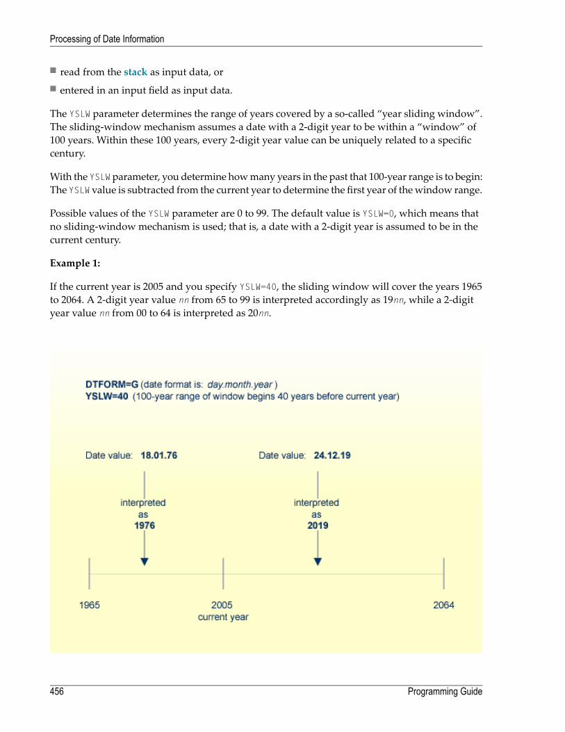
■ read from the stack as input data, or■ entered in an input field as input data.
The YSLW parameter determines the range of years covered by a so-called “year sliding window”.The sliding-window mechanism assumes a date with a 2-digit year to be within a “window” of100 years. Within these 100 years, every 2-digit year value can be uniquely related to a specificcentury.
With the YSLW parameter, you determine howmany years in the past that 100-year range is to begin:The YSLW value is subtracted from the current year to determine the first year of thewindow range.
Possible values of the YSLW parameter are 0 to 99. The default value is YSLW=0, which means thatno sliding-window mechanism is used; that is, a date with a 2-digit year is assumed to be in thecurrent century.
Example 1:
If the current year is 2005 and you specify YSLW=40, the sliding window will cover the years 1965to 2064. A 2-digit year value nn from 65 to 99 is interpreted accordingly as 19nn, while a 2-digityear value nn from 00 to 64 is interpreted as 20nn.
Programming Guide456
Processing of Date Information

Example 2:
If the current year is 2005 and you specify YSLW=20, the sliding window will cover the years 1985to 2084. A 2-digit year value nn from 85 to 99 is interpreted accordingly as 19nn, while a 2-digityear value nn from 00 to 84 is interpreted as 20nn.
Combinations of DFSTACK and YSLW
The following examples illustrate the effects of using various combinations of the parametersDFSTACK and YSLW.
Note: All these examples assume that DTFORM=I applies.
Example 1:
This example assumes the current year to be 2005, and that the parameter settings DFSTACK=S(default) and YSLW=20 apply.
457Programming Guide
Processing of Date Information
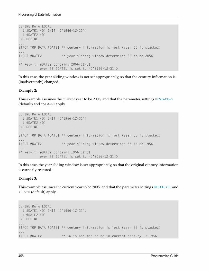
DEFINE DATA LOCAL1 #DATE1 (D) INIT <D'1956-12-31'>1 #DATE2 (D)
END-DEFINE...STACK TOP DATA #DATE1 /* century information is lost (year 56 is stacked)...INPUT #DATE2 /* year sliding window determines 56 to be 2056.../* Result: #DATE2 contains 2056-12-31
even if #DATE1 is set to <D'2156-12-31'>
In this case, the year sliding window is not set appropriately, so that the century information is(inadvertently) changed.
Example 2:
This example assumes the current year to be 2005, and that the parameter settings DFSTACK=S(default) and YSLW=60 apply.
DEFINE DATA LOCAL1 #DATE1 (D) INIT <D'1956-12-31'>1 #DATE2 (D)
END-DEFINE...STACK TOP DATA #DATE1 /* century information is lost (year 56 is stacked)...INPUT #DATE2 /* year sliding window determines 56 to be 1956.../* Result: #DATE2 contains 1956-12-31
even if #DATE1 is set to <D'2056-12-31'>
In this case, the year sliding window is set appropriately, so that the original century informationis correctly restored.
Example 3:
This example assumes the current year to be 2005, and that the parameter settings DFSTACK=C andYSLW=0 (default) apply.
DEFINE DATA LOCAL1 #DATE1 (D) INIT <D'1956-12-31'>1 #DATE2 (D)
END-DEFINE...STACK TOP DATA #DATE1 /* century information is lost (year 56 is stacked)...INPUT #DATE2 /* 56 is assumed to be in current century -> 1956
Programming Guide458
Processing of Date Information

.../* Result: RUNTIME ERROR (UNINTENDED CENTURY CHANGE)
In this case, the century information is (inadvertently) changed.However, this change is interceptedby the DFSTACK=C setting.
Example 4:
This example assumes the current year to be 2005, and that the parameter settings DFSTACK=C andYSLW=60 (default) apply.
DEFINE DATA LOCAL1 #DATE1 (D) INIT <D'2056-12-31'>1 #DATE2 (D)
END-DEFINE...STACK TOP DATA #DATE1 /* century information is lost (year 56 is stacked)...INPUT #DATE2 /* year sliding window determines 56 to be 1956.../* Result: RUNTIME ERROR (UNINTENDED CENTURY CHANGE)
In this case, the century information is changed due to the year sliding window. However, thischange is intercepted by the DFSTACK=C setting.
Year Fixed Window
For information on this topic, see the description of the profile parameter YSLW.
Date Format for Default Page Title - DFTITLE Parameter
The session/profile parameter DFTITLE determines the format of the date in a default page title(as output with a DISPLAY, WRITE or PRINT statement).
The date is output with a 2-digit year component and delimiters (yy-mm-dd).DFTITLE=S
The date is output with a 4-digit year component and delimiters (yyyy-mm-dd).DFTITLE=L
The date is output with a 4-digit year component and no delimiters (yyyymmdd).DFTITLE=I
For each of these output formats, the sequence of the day, month and year components, and thedelimiter characters used, are determined by the DTFORM parameter.
The DFTITLE parameter can be set in the Natural parameter module/file, dynamically when Nat-ural is invoked, or at session level with the system command GLOBALS. It is evaluated at runtime.
459Programming Guide
Processing of Date Information

Example:
This example assumes that DTFORM=I applies.
WRITE 'HELLO'END/*/* Date in page title if DFTITLE=S is set ...: 05-10-31/* Date in page title if DFTITLE=L is set ...: 2005-10-31/* Date in page title if DFTITLE=I is set ...: 20051031
Note: The DFTITLE parameter has no effect on a user-defined page title as specified with aWRITE TITLE statement.
Programming Guide460
Processing of Date Information

47 Text Notation
■ Defining a Text to Be Used with a Statement - the 'text' Notation ............................................................. 462■ Defining a Character to Be Displayed n Times before a Field Value - the 'c'(n) Notation ............................... 463
461

In an INPUT, DISPLAY, WRITE, WRITE TITLE or WRITE TRAILER statement, you can use text notationto define a text to be used in conjunction with such a statement.
Defining a Text to Be Used with a Statement - the 'text' Notation
The text to be used with the statement (for example, a prompting message) must be enclosed ineither apostrophes (') or quotationmarks ("). Do not confuse double apostrophes ('') with a quotationmark (").
Text enclosed in quotation marks can be converted automatically from lower-case letters to uppercase. To switch off automatic conversion, change the settings in the editor profile.
For details, see Program Editor Options, Ignore text constants andUppercase translation (inUsingNatural Studio).
The text itself may be 1 to 72 characters and must not be continued from one line to the next.
Text elements may be concatenated by using a hyphen.
Examples:
DEFINE DATA LOCAL1 #A(A10)END-DEFINE
INPUT 'Input XYZ' (CD=BL) #AWRITE '=' #AWRITE 'Write1 ' - 'Write2 ' - 'Write3' (CD=RE)END
Using Apostrophes as Part of a Text String
The following applies, if Natural profile parameter TQMARK (Translate Quotation Marks) is set toON. This is the default setting.
If you want an apostrophe to be part of a text string that is enclosed in apostrophes, you mustwrite this as double apostrophes ('') or as a quotation mark ("). Either notation will be output as asingle apostrophe.
If you want an apostrophe to be part of a text string that is enclosed in quotation marks, you writethis as a single apostrophe.
Programming Guide462
Text Notation

Examples of Apostrophe:
#FIELDA = 'O''CONNOR'#FIELDA = 'O"CONNOR'#FIELDA = "O'CONNOR"
In all three cases, the result will be:
O'CONNOR
Using Quotation Marks as Part of a Text String
The following applies, if the Natural profile parameter TQ (Translate Quotation Marks) is set toOFF. The default setting is TQ=ON.
If youwant a quotationmark to be part of a text string that is enclosed in single apostrophes, writea quotation mark.
If you want a quotation mark to be part of a text string that is enclosed in quotation marks, writedouble quotation marks ("").
Example of Quotation Mark:
#FIELDA = 'O"CONNOR'#FIELDA = "O""CONNOR"
In both cases, the result will be:
O"CONNOR
Defining a Character to Be Displayed n Times before a Field Value - the 'c'(n)Notation
If a single character is to be output several times as text, you use the following notation:
'c'(n)
As c you specify the character, and as n the number of times the character is to be generated. Themaximum value for n is 249.
463Programming Guide
Text Notation

Example:
WRITE '*'(3)
Instead of apostrophes before and after the character c you can also use quotation marks.
Programming Guide464
Text Notation
48 User Comments
■ Using an Entire Source Code Line for Comments ................................................................................. 466■ Using the Latter Part of a Source Code Line for Comments .................................................................... 467
465

User comments are descriptions or explanatory notes added to or interspersed among the statementsof the source code. Such informationmay be particularly helpful in understanding andmaintenaingsource code that was written or edited by another programmer. Also, the characters marking thebeginning of a comment can be used to temporarily disable the function of a statement or severalsource code lines for test purposes.
Using an Entire Source Code Line for Comments
If you wish to use an entire source-code line for a user comment, you enter one of the followingat the beginning of the line:
■ an asterisk and a blank (* ),■ two asterisks (**), or■ a slash and an asterisk (/*).
* USER COMMENT** USER COMMENT/* USER COMMENT
Example:
As can be seen from the following example, comment lines may also be used to provide for a clearsource code structure.
** Example 'LOGICX03': BREAK option in logical condition************************************************************************DEFINE DATA LOCAL1 EMPLOY-VIEW VIEW OF EMPLOYEES
2 NAME2 FIRST-NAME2 BIRTH
*1 #BIRTH (A8)END-DEFINE*LIMIT 10READ EMPLOY-VIEW BY BIRTH
MOVE EDITED BIRTH (EM=YYYYMMDD) TO #BIRTH/*IF BREAK OF #BIRTH /6/
NEWPAGE IF LESS THAN 5 LINES LEFTWRITE / '-' (50) /
END-IF/*DISPLAY NOTITLE BIRTH (EM=YYYY-MM-DD) NAME FIRST-NAME
Programming Guide466
User Comments

END-READEND
Using the Latter Part of a Source Code Line for Comments
If you wish to use only the latter part of a source-code line for a user comment, you enter a blank,a slash and an asterisk ( /*); the remainder of the line after this notation is thusmarked as a comment:
ADD 5 TO #A /* USER COMMENT
Example:
** Example 'LOGICX04': IS option as format/length check************************************************************************DEFINE DATA LOCAL1 #FIELDA (A10) /* INPUT FIELD TO BE CHECKED1 #FIELDB (N5) /* RECEIVING FIELD OF VAL FUNCTION1 #DATE (A10) /* INPUT FIELD FOR DATEEND-DEFINE*INPUT #DATE #FIELDAIF #DATE IS(D)
IF #FIELDA IS (N5)COMPUTE #FIELDB = VAL(#FIELDA)WRITE NOTITLE 'VAL FUNCTION OK' // '=' #FIELDA '=' #FIELDB
ELSEREINPUT 'FIELD DOES NOT FIT INTO N5 FORMAT'
MARK *#FIELDAEND-IF
ELSEREINPUT 'INPUT IS NOT IN DATE FORMAT (YY-MM-DD) '
MARK *#DATEEND-IF*END
467Programming Guide
User Comments

468

49 Logical Condition Criteria
■ Introduction .................................................................................................................................. 470■ Relational Expression ..................................................................................................................... 471■ Extended Relational Expression ....................................................................................................... 475■ Evaluation of a Logical Variable ........................................................................................................ 476■ Fields Used within Logical Condition Criteria ....................................................................................... 477■ Logical Operators in Complex Logical Expressions ............................................................................... 479■ BREAK Option - Compare Current Value with Value of Previous Loop Pass .............................................. 480■ IS Option - Check whether Content of Alphanumeric or Unicode Field can be Converted ............................. 482■ MASK Option - Check Selected Positions of a Field for Specific Content ................................................... 484■ MASK Option Compared with IS Option ............................................................................................. 491■ MODIFIED Option - Check whether Field Content has been Modified ....................................................... 493■ SCAN Option - Scan for a Value within a Field ..................................................................................... 494■ SPECIFIED Option - Check whether a Value is Passed for an Optional Parameter ...................................... 496
469
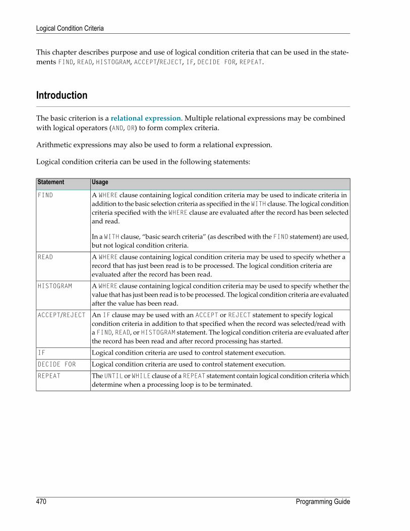
This chapter describes purpose and use of logical condition criteria that can be used in the state-ments FIND, READ, HISTOGRAM, ACCEPT/REJECT, IF, DECIDE FOR, REPEAT.
Introduction
The basic criterion is a relational expression. Multiple relational expressions may be combinedwith logical operators (AND, OR) to form complex criteria.
Arithmetic expressions may also be used to form a relational expression.
Logical condition criteria can be used in the following statements:
UsageStatement
A WHERE clause containing logical condition criteria may be used to indicate criteria inaddition to the basic selection criteria as specified in the WITH clause. The logical condition
FIND
criteria specified with the WHERE clause are evaluated after the record has been selectedand read.
In a WITH clause, “basic search criteria” (as describedwith the FIND statement) are used,but not logical condition criteria.
A WHERE clause containing logical condition criteria may be used to specify whether arecord that has just been read is to be processed. The logical condition criteria areevaluated after the record has been read.
READ
A WHERE clause containing logical condition criteria may be used to specify whether thevalue that has just been read is to be processed. The logical condition criteria are evaluatedafter the value has been read.
HISTOGRAM
An IF clause may be used with an ACCEPT or REJECT statement to specify logicalcondition criteria in addition to that specified when the record was selected/read with
ACCEPT/REJECT
a FIND, READ, or HISTOGRAM statement. The logical condition criteria are evaluated afterthe record has been read and after record processing has started.
Logical condition criteria are used to control statement execution.IF
Logical condition criteria are used to control statement execution.DECIDE FOR
The UNTIL or WHILE clause of a REPEAT statement contain logical condition criteriawhichdetermine when a processing loop is to be terminated.
REPEAT
Programming Guide470
Logical Condition Criteria

Relational Expression
Syntax:
operand2operand1
EQ=EQUALEQUAL TONE^=<>NOT =NOT EQNOTEQUALNOT EQUALNOT EQUAL TOLTLESS THAN<GEGREATER EQUAL>=NOT <NOT LTGTGREATER THAN>LELESS EQUAL<=NOT >NOT GT
Operand Definition Table:
DynamicDefinition
ReferencingPermitted
Possible FormatsPossible StructureOperand
yesyesOGLTDBFIPNUAENASCoperand1
noyesOGLTDBFIPNUAENASCoperand2
For an explanation of the Operand Definition Table shown above, see Syntax Symbols and OperandDefinition Tables in the Statements documentation.
In the “Possible Structure” column of the table above, “E” stands for arithmetic expressions; thatis, any arithmetic expression may be specified as an operand within the relational expression. For
471Programming Guide
Logical Condition Criteria

further information on arithmetic expressions, see arithmetic-expression in the COMPUTE statementdescription.
Explanation of the comparison operators:
ExplanationComparison Operator
equal toEQ=EQUALEQUAL TO
not equal toNE^=<>NOT =NOT EQNOTEQUALNOT EQUALNOT EQUAL TO
less thanLTLESS THAN<
greater than or equal toGEGREATER EQUAL>=
not less thanNOT <NOT LT
greater thanGTGREATER THAN>
less than or equal toLELESS EQUAL<=
not greater thanNOT >NOT GT
Examples of Relational Expressions:
IF NAME = 'SMITH'IF LEAVE-DUE GT 40IF NAME = #NAME
For information on comparing arrays in a relational expression, see Processing of Arrays.
Note: If a floating-point operand is used, comparison is performed in floating point.Floating-point numbers as suchhave only a limitedprecision; therefore, rounding/truncation
Programming Guide472
Logical Condition Criteria
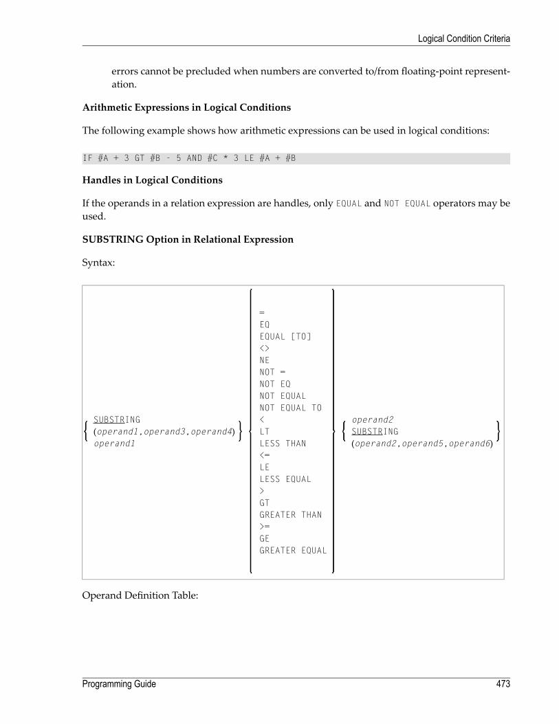
errors cannot be precluded when numbers are converted to/from floating-point represent-ation.
Arithmetic Expressions in Logical Conditions
The following example shows how arithmetic expressions can be used in logical conditions:
IF #A + 3 GT #B - 5 AND #C * 3 LE #A + #B
Handles in Logical Conditions
If the operands in a relation expression are handles, only EQUAL and NOT EQUAL operators may beused.
SUBSTRING Option in Relational Expression
Syntax:
operand2
=
SUBSTRING(operand1,operand3,operand4) SUBSTRING
(operand2,operand5,operand6)
EQ
operand1
EQUAL [TO]<>NENOT =NOT EQNOT EQUALNOT EQUAL TO<LTLESS THAN<=LELESS EQUAL>GTGREATER THAN>=GEGREATER EQUAL
Operand Definition Table:
473Programming Guide
Logical Condition Criteria

DynamicDefinition
ReferencingPermitted
Possible FormatsPossible StructureOperand
yesyesBUANASCoperand1
noyesBUANASCoperand2
noyesBIPNSCoperand3
noyesIPNSCoperand4
noyesIPNSCoperand5
noyesIPNSCoperand6
With the SUBSTRING option, you can compare a part of an alphanumeric, a binary or a Unicodefield. After the field name (operand1) you specify first the starting position (operand3) and thenthe length (operand4) of the field portion to be compared.
Also, you can compare a field valuewith part of another field value. After the field name (operand2)you specify first the starting position (operand5) and then the length (operand6) of the field portionoperand1 is to be compared with.
You can also combine both forms, that is, you can specify a SUBSTRING for both operand1 andoperand2.
Examples:
The following expression compares the 5th to 12th position inclusive of the value in field #Awiththe value of field #B:
SUBSTRING(#A,5,8) = #B
- where 5 is the starting position and 8 is the length.
The following expression compares the value of field #Awith the 3rd to 6th position inclusive ofthe value in field #B:
#A = SUBSTRING(#B,3,4)
Note: If you omit operand3/operand5, the starting position is assumed to be 1. If you omitoperand4/operand6, the length is assumed to be from the starting position to the end of thefield.
Programming Guide474
Logical Condition Criteria

Extended Relational Expression
Syntax:
operand2operand1=EQEQUAL [TO]
operand3OR=EQEQUAL [TO]
THRU operand4 [BUT NOT operand5 [THRU operand6]]
Operand Definition Table:
DynamicDefinition
ReferencingPermitted
Possible FormatsPossible StructureOperand
noyesOGTDBFIPNUAEN*ASCoperand1
noyesOGTDBFIPNUAEN*ASCoperand2
noyesOGTDBFIPNUAEN*ASCoperand3
noyesOGTDBFIPNUAEN*ASCoperand4
noyesOGTDBFIPNUAEN*ASCoperand5
noyesOGTDBFIPNUAEN*ASCoperand6
* Mathematical functions and system variables are permitted. Break functions are not permitted.
operand3 can also be specified using a MASK or SCAN option; that is, it can be specified as:
MASK (mask-definition) [operand]
MASK operand
SCAN operand
For details on these options, see the sectionsMASK Option and SCAN Option.
475Programming Guide
Logical Condition Criteria

Examples:
IF #A = 2 OR = 4 OR = 7IF #A = 5 THRU 11 BUT NOT 7 THRU 8
Evaluation of a Logical Variable
Syntax:
operand1
This option is used in conjunction with a logical variable (format L). A logical variable may takethe value TRUE or FALSE. As operand1 you specify the name of the logical variable to be used.
Operand Definition Table:
Dynamic DefinitionReferencing PermittedPossible FormatsPossible StructureOperand
nonoLASCoperand1
Example of Logical Variable:
** Example 'LOGICX05': Logical variable in logical condition************************************************************************DEFINE DATA LOCAL1 #SWITCH (L) INIT <true>1 #INDEX (I1)END-DEFINE*FOR #INDEX 1 5
WRITE NOTITLE #SWITCH (EM=FALSE/TRUE) 5X 'INDEX =' #INDEXWRITE NOTITLE #SWITCH (EM=OFF/ON) 7X 'INDEX =' #INDEXIF #SWITCH
MOVE FALSE TO #SWITCHELSE
MOVE TRUE TO #SWITCHEND-IF/*SKIP 1
END-FOREND
Output of Program LOGICX05:
Programming Guide476
Logical Condition Criteria

TRUE INDEX = 1ON INDEX = 1
FALSE INDEX = 2OFF INDEX = 2
TRUE INDEX = 3ON INDEX = 3
FALSE INDEX = 4OFF INDEX = 4
TRUE INDEX = 5ON INDEX = 5
Fields Used within Logical Condition Criteria
Database fields and user-defined variables may be used to construct logical condition criteria. Adatabase field which is a multiple-value field or is contained in a periodic group can also be used.If a range of values for a multiple-value field or a range of occurrences for a periodic group isspecified, the condition is true if the search value is found in any value/occurrence within thespecified range.
Each value used must be compatible with the field used on the opposite side of the expression.Decimal notation may be specified only for values used with numeric fields, and the number ofdecimal positions of the value must agree with the number of decimal positions defined for thefield.
If the operands are not of the same format, the second operand is converted to the format of thefirst operand.
Note: A numeric constant without decimal point notation is stored with format I for thevalues -2147483648 to +2147483647, seeNumeric Constants. Consequently the comparisonwith such an integer constant as operand1 is performed by converting operand2 to a integervalue. This means that the digits after the decimal point of operand2 are not considereddue to truncation.
Example:
477Programming Guide
Logical Condition Criteria

IF 0 = 0.5 /* is true because 0.5 (operand2) is converted to 0 (format I of ↩operand1) IF 0.0 = 0.5 /* is false IF 0.5 = 0 /* is false IF 0.5 = 0.0 /* is false ↩
The following table shows which operand formats can be used together in a logical condition:
operand2operand1
OHGHPNLFITDBn (n>=5)Bn (n=<4)UA
YYYYA
[2][2]YYU
YYYYYYYYYYBn (n=<4)
YYYYBn (n>=5)
YYYYYYYD
YYYYYYYT
YYYYYYYI
YYYYYYYFL
YYYYYYYN
YYYYYYYP
YGH [1]
YOH [1]
Notes:
1. [1] where GH = GUI handle, OH = object handle.
2. [2] The binary value will be assumed to contain Unicode code points, and the comparison isperformed as for a comparison of two Unicode values. The length of the binary field must beeven.
If two values are compared as alphanumeric values, the shorter value is assumed to be extendedwith trailing blanks in order to get the same length as the longer value.
If two values are compared as binary values, the shorter value is assumed to be extended withleading binary zeroes in order to get the same length as the longer value.
If two values are compared asUnicode values, trailing blanks are removed from both values beforethe ICU collation algorithm is used to compare the two resulting values. See also Logical ConditionCriteria in the Unicode and Code Page Support documentation.
Programming Guide478
Logical Condition Criteria

Comparison Examples:
A1(A1) := 'A' A5(A5) := 'A ' B1(B1) := H'FF' B5(B5) := H'00000000FF' U1(U1) := UH'00E4' U2(U2) := UH'00610308' IF A1 = A5 THEN ... /* TRUE IF B1 = B5 THEN ... /* TRUEIF U1 = U2 THEN ... /* TRUE ↩
If an array is compared with a scalar value, each element of the array will be compared with thescalar value. The condition will be true if at least one of the array elements meets the condition(OR operation).
If an array is comparedwith an array, each element in the array is comparedwith the correspondingelement of the other array. The result is true only if all element comparisons meet the condition(AND operation).
See also Processing of Arrays.
Note: An Adabas phonetic descriptor cannot be used within a logical condition.
Examples of Logical Condition Criteria:
FIND EMPLOYEES-VIEW WITH CITY = 'BOSTON' WHERE SEX = 'M'READ EMPLOYEES-VIEW BY NAME WHERE SEX = 'M'ACCEPT IF LEAVE-DUE GT 45IF #A GT #B THEN COMPUTE #C = #A + #BREPEAT UNTIL #X = 500
Logical Operators in Complex Logical Expressions
Logical condition criteria may be combined using the Boolean operators AND, OR, and NOT. Paren-theses may also be used to indicate logical grouping.
The operators are evaluated in the following order:
479Programming Guide
Logical Condition Criteria
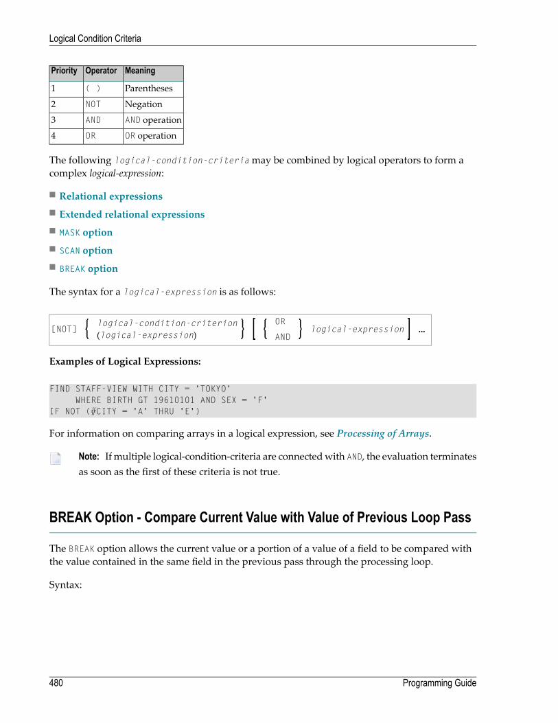
MeaningOperatorPriority
Parentheses( )1
NegationNOT2
AND operationAND3
OR operationOR4
The following logical-condition-criteriamay be combined by logical operators to form acomplex logical-expression:
■ Relational expressions■ Extended relational expressions■ MASK option■ SCAN option■ BREAK option
The syntax for a logical-expression is as follows:
logical-expressionOR
[NOT]logical-condition-criterion(logical-expression) AND
Examples of Logical Expressions:
FIND STAFF-VIEW WITH CITY = 'TOKYO'WHERE BIRTH GT 19610101 AND SEX = 'F'
IF NOT (#CITY = 'A' THRU 'E')
For information on comparing arrays in a logical expression, see Processing of Arrays.
Note: If multiple logical-condition-criteria are connectedwith AND, the evaluation terminatesas soon as the first of these criteria is not true.
BREAK Option - Compare Current Value with Value of Previous Loop Pass
The BREAK option allows the current value or a portion of a value of a field to be compared withthe value contained in the same field in the previous pass through the processing loop.
Syntax:
Programming Guide480
Logical Condition Criteria

BREAK [OF] operand1 [/n/]
Operand Definition Table:
Dynamic DefinitionReferencingPermitted
Possible FormatsPossible StructureOperand
noyesLTDBFIPNUASoperand1
Syntax Element Description:
Specifies the control field which is to be checked. A specific occurrence of an array can also beused as a control field.
operand1
The notation /n/may be used to indicate that only the first n positions (counting from left toright) of the control field are to be checked for a change in value. This notation can only beused with operands of format A, B, N, or P.
/n/
The result of the BREAK operation is true when a change in the specified positions of the fieldoccurs. The result of the BREAK operation is not true if an AT END OF DATA condition occurs.
Example:
In this example, a check is made for a different value in the first position of the fieldFIRST-NAME.
BREAK FIRST-NAME /1/
Natural system functions (which are available with the AT BREAK statement) are not availablewith this option.
Example of BREAK Option:
** Example 'LOGICX03': BREAK option in logical condition************************************************************************DEFINE DATA LOCAL1 EMPLOY-VIEW VIEW OF EMPLOYEES
2 NAME2 FIRST-NAME2 BIRTH
*1 #BIRTH (A8)END-DEFINE*LIMIT 10READ EMPLOY-VIEW BY BIRTH
MOVE EDITED BIRTH (EM=YYYYMMDD) TO #BIRTH/*IF BREAK OF #BIRTH /6/
NEWPAGE IF LESS THAN 5 LINES LEFTWRITE / '-' (50) /
481Programming Guide
Logical Condition Criteria

END-IF/*DISPLAY NOTITLE BIRTH (EM=YYYY-MM-DD) NAME FIRST-NAME
END-READEND
Output of Program LOGICX03:
DATE NAME FIRST-NAMEOF
BIRTH---------- -------------------- --------------------
1940-01-01 GARRET WILLIAM1940-01-09 TAILOR ROBERT1940-01-09 PIETSCH VENUS1940-01-31 LYTTLETON BETTY
--------------------------------------------------
1940-02-02 WINTRICH MARIA1940-02-13 KUNEY MARY1940-02-14 KOLENCE MARSHA1940-02-24 DILWORTH TOM
--------------------------------------------------
1940-03-03 DEKKER SYLVIA1940-03-06 STEFFERUD BILL
IS Option - Check whether Content of Alphanumeric or Unicode Field can beConverted
Syntax:
operand1 IS (format)
This option is used to check whether the content of an alphanumeric or Unicode field (operand1)can be converted to a specific other format.
Operand Definition Table:
Programming Guide482
Logical Condition Criteria

Dynamic DefinitionReferencing PermittedPossible FormatsPossible StructureOperand
noyesUANASCoperand1
The format for which the check is performed can be:
Numeric with length ll.ll.Nll.ll
Floating point with length ll.Fll
Date. The following date formats are possible: dd-mm-yy, dd-mm-yyyy, ddmmyyyy (dd = day,mm = month, yy or yyyy = year). The sequence of the day, month and year components as well
D
as the characters between the components are determined by the profile parameter DTFORM(which is described in the Parameter Reference).
Time (according to the default time display format).T
Packed numeric with length ll.ll.Pll.ll
Integer with length ll.Ill
When the check is performed, leading and trailing blanks in operand1will be ignored.
The IS option may, for example, be used to check the content of a field before the mathematicalfunction VAL (extract numeric value from an alphanumeric field) is used to ensure that it will notresult in a runtime error.
Note: The IS option cannot be used to check if the value of an alphanumeric field is in thespecified “format”, but if it can be converted to that “format”. To check if a value is in aspecific format, you can use the MASK option. For further information, seeMASK OptionCompared with IS Option and Checking Packed or Unpacked Numeric Data.
Example of IS Option:
** Example 'LOGICX04': IS option as format/length check************************************************************************DEFINE DATA LOCAL1 #FIELDA (A10) /* INPUT FIELD TO BE CHECKED1 #FIELDB (N5) /* RECEIVING FIELD OF VAL FUNCTION1 #DATE (A10) /* INPUT FIELD FOR DATEEND-DEFINE*INPUT #DATE #FIELDAIF #DATE IS(D)
IF #FIELDA IS (N5)COMPUTE #FIELDB = VAL(#FIELDA)WRITE NOTITLE 'VAL FUNCTION OK' // '=' #FIELDA '=' #FIELDB
ELSEREINPUT 'FIELD DOES NOT FIT INTO N5 FORMAT'
MARK *#FIELDAEND-IF
ELSEREINPUT 'INPUT IS NOT IN DATE FORMAT (YY-MM-DD) '
483Programming Guide
Logical Condition Criteria
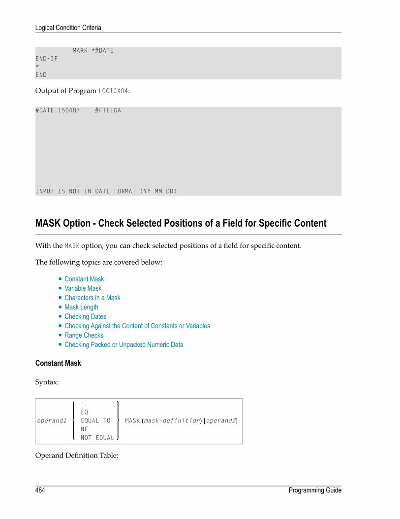
MARK *#DATEEND-IF*END
Output of Program LOGICX04:
#DATE 150487 #FIELDA
INPUT IS NOT IN DATE FORMAT (YY-MM-DD)
MASK Option - Check Selected Positions of a Field for Specific Content
With the MASK option, you can check selected positions of a field for specific content.
The following topics are covered below:
■ Constant Mask■ Variable Mask■ Characters in a Mask■ Mask Length■ Checking Dates■ Checking Against the Content of Constants or Variables■ Range Checks■ Checking Packed or Unpacked Numeric Data
Constant Mask
Syntax:
MASK (mask-definition) [operand2]operand1
=EQEQUAL TONENOT EQUAL
Operand Definition Table:
Programming Guide484
Logical Condition Criteria

Dynamic DefinitionReferencingPermitted
Possible FormatsPossible StructureOperand
noyesPNUANASCoperand1
noyesBPNUASCoperand2
operand2 can only be used if the mask-definition contains at least one X. operand1 and operand2must be format-compatible:
■ If operand1 is of format A, operand2must be of format A, B, N or U.■ If operand1 is of format U, operand2must be of format A, B, N or U.■ If operand1 is of format N or P, operand2must be of format N or P.
An X in the mask-definition selects the corresponding positions of the content of operand1 andoperand2 for comparison.
Variable Mask
Apart from a constant mask-definition (see above), you may also specify a variable mask defin-ition.
Syntax:
MASK operand2operand1
=EQEQUAL TONENOT EQUAL
Operand Definition Table:
Dynamic DefinitionReferencingPermitted
Possible FormatsPossible StructureOperand
noyesPNUANASCoperand1
noyesUASoperand2
The content of operand2will be taken as the mask definition. Trailing blanks in operand2will beignored.
■ If operand1 is of format A, N or P, operand2must be of format A.■ If operand1 is of format U, operand2must be of format U.
485Programming Guide
Logical Condition Criteria
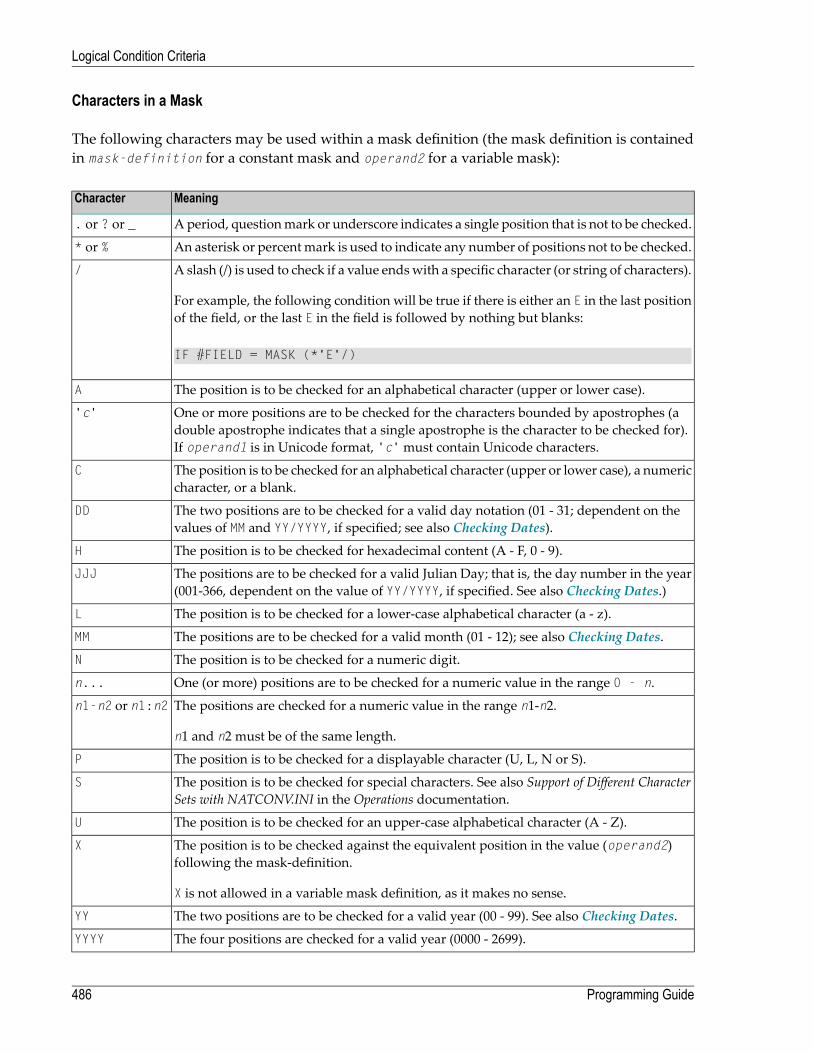
Characters in a Mask
The following characters may be used within a mask definition (the mask definition is containedin mask-definition for a constant mask and operand2 for a variable mask):
MeaningCharacter
Aperiod, questionmark or underscore indicates a single position that is not to be checked.. or ? or _
An asterisk or percentmark is used to indicate any number of positions not to be checked.* or %
A slash (/) is used to check if a value endswith a specific character (or string of characters).
For example, the following condition will be true if there is either an E in the last positionof the field, or the last E in the field is followed by nothing but blanks:
/
IF #FIELD = MASK (*'E'/)
The position is to be checked for an alphabetical character (upper or lower case).A
One or more positions are to be checked for the characters bounded by apostrophes (adouble apostrophe indicates that a single apostrophe is the character to be checked for).If operand1 is in Unicode format, 'c'must contain Unicode characters.
'c'
The position is to be checked for an alphabetical character (upper or lower case), a numericcharacter, or a blank.
C
The two positions are to be checked for a valid day notation (01 - 31; dependent on thevalues of MM and YY/YYYY, if specified; see also Checking Dates).
DD
The position is to be checked for hexadecimal content (A - F, 0 - 9).H
The positions are to be checked for a valid Julian Day; that is, the day number in the year(001-366, dependent on the value of YY/YYYY, if specified. See also Checking Dates.)
JJJ
The position is to be checked for a lower-case alphabetical character (a - z).L
The positions are to be checked for a valid month (01 - 12); see also Checking Dates.MM
The position is to be checked for a numeric digit.N
One (or more) positions are to be checked for a numeric value in the range 0 - n.n...
The positions are checked for a numeric value in the range n1-n2.
n1 and n2 must be of the same length.
n1-n2 or n1:n2
The position is to be checked for a displayable character (U, L, N or S).P
The position is to be checked for special characters. See also Support of Different CharacterSets with NATCONV.INI in the Operations documentation.
S
The position is to be checked for an upper-case alphabetical character (A - Z).U
The position is to be checked against the equivalent position in the value (operand2)following the mask-definition.
X is not allowed in a variable mask definition, as it makes no sense.
X
The two positions are to be checked for a valid year (00 - 99). See also Checking Dates.YY
The four positions are checked for a valid year (0000 - 2699).YYYY
Programming Guide486
Logical Condition Criteria

MeaningCharacter
The position is to be checked for a character whose left half-byte is hexadecimally 3 or 7,and whose right half-byte is hexadecimally 0 - 9.
Thismay be used to correctly check for numeric digits in negative numbers.With N (whichindicates a position to be checked for a numeric digit), a check for numeric digits in negative
Z
numbers leads to incorrect results, because the sign of the number is stored in the lastdigit of the number, causing that digit to be hexadecimally represented as non-numeric.
Within a mask, use only one Z for each sequence of numeric digits that is checked.
Mask Length
The length of the mask determines how many positions are to be checked.
Example:
DEFINE DATA LOCAL1 #CODE (A15)END-DEFINE...IF #CODE = MASK (NN'ABC'....NN)...
In the above example, the first two positions of #CODE are to be checked for numeric content. Thethree following positions are checked for the contents ABC. The next four positions are not to bechecked. Positions ten and eleven are to be checked for numeric content. Positions twelve to fifteenare not to be checked.
Checking Dates
Only one date may be checked within a given mask. When the same date component (JJJ, DD, MM,YY or YYYY) is specifiedmore than once in themask, only the value of the last occurrence is checkedfor consistency with other date components.
When dates are checked for a day (DD) and no month (MM) is specified in the mask, the currentmonth will be assumed.
When dates are checked for a day (DD) or a Julian day (JJJ) and no year (YY or YYYY) is specifiedin the mask, the current year will be assumed.
When dates are checked for a 2-digit year (YY), the current century will be assumed if no Slidingor FixedWindow is set. Formore details about Sliding or FixedWindows, refer to profile parameterYSLW in the Parameter Reference.
487Programming Guide
Logical Condition Criteria

Example 1:
MOVE 1131 TO #DATE (N4)IF #DATE = MASK (MMDD)
In this example,month andday are checked for validity. The value formonth (11)will be consideredvalid, whereas the value for day (31) will be invalid since the 11th month has only 30 days.
Example 2:
IF #DATE(A8) = MASK (MM'/'DD'/'YY)
In this example, the content of the field #DATE is be checked for a valid date with the formatMM/DD/YY (month/day/year).
Example 3:
IF #DATE (A8) = MASK (1950-2020MMDD)
In this example, the content of field #DATE is checked for a four-digit number in the range 1950 to2020 followed by a valid month and day in the current year.
Note: Although apparent, the above mask does not allow to check for a valid date in theyears 1950 through 2020, because the numeric value range 1950-2020 is checked independentof the validation of month and day. The check will deliver the intended results except forFebruary, 29, where the result depends on whether the current year is a leap year or not.To check for a specific year range in addition to the date validation, code one check for thedate validation and another for the range validation:
IF #DATE (A8) = MASK (YYYYMMDD) AND #DATE = MASK (1950-2020)
Example 4:
IF #DATE (A4) = MASK (19-20YY)
In this example, the content of field #DATE is checked for a two-digit number in the range 19 to 20followed by a valid two-digit year (00 through 99). The century is supplied byNatural as describedabove.
Note: Although apparent, the above mask does not allow to check for a valid year in therange 1900 through 2099, because the numeric value range 19-20 is checked independentof the year validation. To check for year ranges, code one check for the date validation andanother for the range validation:
Programming Guide488
Logical Condition Criteria
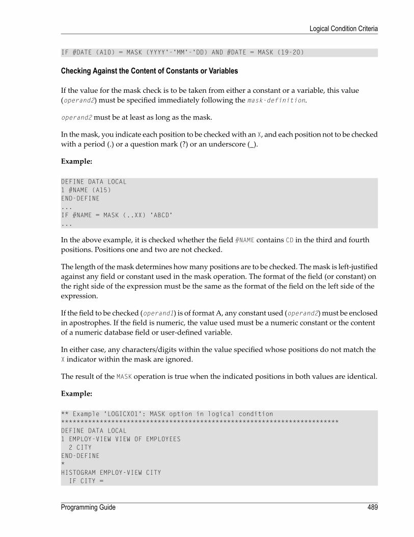
IF #DATE (A10) = MASK (YYYY'-'MM'-'DD) AND #DATE = MASK (19-20)
Checking Against the Content of Constants or Variables
If the value for the mask check is to be taken from either a constant or a variable, this value(operand2) must be specified immediately following the mask-definition.
operand2must be at least as long as the mask.
In themask, you indicate each position to be checkedwith an X, and each position not to be checkedwith a period (.) or a question mark (?) or an underscore (_).
Example:
DEFINE DATA LOCAL1 #NAME (A15)END-DEFINE...IF #NAME = MASK (..XX) 'ABCD'...
In the above example, it is checked whether the field #NAME contains CD in the third and fourthpositions. Positions one and two are not checked.
The length of themask determines howmany positions are to be checked. Themask is left-justifiedagainst any field or constant used in the mask operation. The format of the field (or constant) onthe right side of the expression must be the same as the format of the field on the left side of theexpression.
If the field to be checked (operand1) is of format A, any constant used (operand2) must be enclosedin apostrophes. If the field is numeric, the value used must be a numeric constant or the contentof a numeric database field or user-defined variable.
In either case, any characters/digits within the value specified whose positions do not match theX indicator within the mask are ignored.
The result of the MASK operation is true when the indicated positions in both values are identical.
Example:
** Example 'LOGICX01': MASK option in logical condition************************************************************************DEFINE DATA LOCAL1 EMPLOY-VIEW VIEW OF EMPLOYEES
2 CITYEND-DEFINE*HISTOGRAM EMPLOY-VIEW CITY
IF CITY =
489Programming Guide
Logical Condition Criteria

MASK (....XX) '....NN'
DISPLAY NOTITLE CITY *NUMBEREND-IF
END-HISTOGRAM*END
In the above example, the record will be accepted if the fifth and sixth positions of the field CITYeach contain the character N.
Range Checks
When performing range checks, the number of positions verified in the supplied variable is definedby the precision of the value supplied in themask specification. For example, amask of (...193...)will verify positions 4 to 6 for a three-digit number in the range 000 to 193.
Additional Examples of Mask Definitions:
■ In this example, each character of #NAME is checked for an alphabetical character:
IF #NAME (A10) = MASK (AAAAAAAAAA)
■ In this example, positions 4 to 6 of #NUMBER are checked for a numeric value:
IF #NUMBER (A6) = MASK (...NNN)
■ In this example, positions 4 to 6 of #VALUE are to be checked for the value 123:
IF #VALUE(A10) = MASK (...'123')
■ This examplewill check if #LICENSE contains a license numberwhich beginswith NY- andwhoselast five characters are identical to the last five positions of #VALUE:
DEFINE DATA LOCAL1 #VALUE(A8)1 #LICENSE(A8)END-DEFINEINPUT 'ENTER KNOWN POSITIONS OF LICENSE PLATE:' #VALUEIF #LICENSE = MASK ('NY-'XXXXX) #VALUE
■ The following conditionwould bemet by any valuewhich contains NAT and AL nomatter whichand howmany other characters are between NAT and AL (this would include the values NATURALand NATIONALITY as well as NATAL):
Programming Guide490
Logical Condition Criteria

MASK('NAT'*'AL')
Checking Packed or Unpacked Numeric Data
Legacy applications often have packed or unpacked numeric variables redefined with alphanu-meric or binary fields. Such redefinitions are not recommended, because using the packed or un-packed variable in an assignment or computation may lead to errors or unpredictable results. Tovalidate the contents of such a redefined variable before the variable is used, use the N option (seeCharacters in a Mask) as many as number of digits - 1 times followed by a single Z option.
Examples :
IF #P1 (P1) = MASK (Z)IF #N4 (N4) = MASK (NNNZ)IF #P5 (P5) = MASK (NNNNZ)
For further information about checking field contents, seeMASKOptionComparedwith ISOption.
MASK Option Compared with IS Option
This section points out the difference between MASK option and IS option and contains a sampleprogram to illustrate the difference.
The IS option can be used to check whether the content of an alphanumeric or Unicode field canbe converted to a specific other format, but it cannot be used to check if the value of an alphanu-meric field is in the specified format.
The MASK option can be used to validate the contents of a redefined packed or unpacked numericvariable.
Example Illustrating the Difference:
** Example 'LOGICX09': MASK versus IS option in logical condition ************************************************************************DEFINE DATA LOCAL 1 #A2 (A2) 1 REDEFINE #A2 2 #N2 (N2) 1 REDEFINE #A2 2 #P3 (P3) 1 #CONV-N2 (N2) 1 #CONV-P3 (P3) END-DEFINE * #A2 := '12' WRITE NOTITLE 'Assignment #A2 := "12" results in:'
491Programming Guide
Logical Condition Criteria

PERFORM SUBTEST #A2 := '-1' WRITE NOTITLE / 'Assignment #A2 := "-1" results in:'PERFORM SUBTEST #N2 := 12 WRITE NOTITLE / 'Assignment #N2 := 12 results in:'PERFORM SUBTEST #N2 := -1 WRITE NOTITLE / 'Assignment #N2 := -1 results in:'PERFORM SUBTEST #P3 := 12 WRITE NOTITLE / 'Assignment #P3 := 12 results in:'PERFORM SUBTEST #P3 := -1 WRITE NOTITLE / 'Assignment #P3 := -1 results in:'PERFORM SUBTEST * ↩ DEFINE SUBROUTINE SUBTEST IF #A2 IS (N2) THEN #CONV-N2 := VAL(#A2) WRITE NOTITLE 12T '#A2 can be converted to' #CONV-N2 '(N2)' END-IF IF #A2 IS (P3) THEN #CONV-P3 := VAL(#A2) WRITE NOTITLE 12T '#A2 can be converted to' #CONV-P3 '(P3)' END-IF IF #N2 = MASK(NZ) THEN WRITE NOTITLE 12T '#N2 contains the valid unpacked number' #N2END-IF IF #P3 = MASK(NNZ) THEN WRITE NOTITLE 12T '#P3 contains the valid packed number' #P3 END-IF END-SUBROUTINE * END ↩
Output of Program LOGICX09:
Assignment #A2 := '12' results in:#A2 can be converted to 12 (N2)#A2 can be converted to 12 (P3)#N2 contains the valid unpacked number 12
Assignment #A2 := '-1' results in:#A2 can be converted to -1 (N2)#A2 can be converted to -1 (P3)
Assignment #N2 := 12 results in:#A2 can be converted to 12 (N2)#A2 can be converted to 12 (P3)#N2 contains the valid unpacked number 12
Programming Guide492
Logical Condition Criteria

Assignment #N2 := -1 results in:#N2 contains the valid unpacked number -1
Assignment #P3 := 12 results in:#P3 contains the valid packed number 12
Assignment #P3 := -1 results in:#P3 contains the valid packed number -1
MODIFIED Option - Check whether Field Content has been Modified
Syntax:
operand1 [NOT] MODIFIED
This option is used to determine whether the content of a field has been modified during the exe-cution of an INPUT or PROCESS PAGE statement. As a precondition, a control variable must havebeen assigned using the parameter CV.
Operand Definition Table:
Dynamic DefinitionReferencing PermittedPossible FormatsPossible StructureOperand
nonoCASoperand1
Attribute control variables referenced in an INPUT or PROCESS PAGE statement are always assignedthe status “not modified” when the map is transmitted to the terminal.
Whenever the content of a field referencing an attribute control variable is modified, the attributecontrol variable has been assigned the status “modified”.Whenmultiple fields reference the sameattribute control variable, the variable is marked “modified” if any of these fields is modified.
If operand1 is an array, the result will be true if at least one of the array elements has been assignedthe status “modified” (OR operation).
Example of MODIFIED Option:
** Example 'LOGICX06': MODIFIED option in logical condition************************************************************************DEFINE DATA LOCAL1 #ATTR (C)1 #A (A1)1 #B (A1)END-DEFINE*MOVE (AD=I) TO #ATTR
493Programming Guide
Logical Condition Criteria

*INPUT (CV=#ATTR) #A #BIF #ATTR NOT MODIFIED
WRITE NOTITLE 'FIELD #A OR #B HAS NOT BEEN MODIFIED'END-IF*IF #ATTR MODIFIED
WRITE NOTITLE 'FIELD #A OR #B HAS BEEN MODIFIED'END-IF*END
Output of Program LOGICX06:
#A #B
After entering any value and pressing ENTER, the following output is displayed:
FIELD #A OR #B HAS BEEN MODIFIED
SCAN Option - Scan for a Value within a Field
Syntax:
SCANoperand1operand2
=
(operand2)
EQEQUAL TONENOT EQUAL
Operand Definition Table:
Dynamic DefinitionReferencingPermitted
Possible FormatsPossible StructureOperand
noyesPNUANASCoperand1
noyesB*UASCoperand2
* operand2may only be binary if operand1 is of format A or U. If operand1 is of format U and op-erand2 is of format B, then the length of operand2must be even.
The SCAN option is used to scan for a specific value within a field.
Programming Guide494
Logical Condition Criteria

The characters used in the SCAN option (operand2) may be specified as an alphanumeric or Unicodeconstant (a character string bounded by apostrophes) or the contents of an alphanumeric orUnicodedatabase field or user-defined variable.
Caution: Trailing blanks are automatically eliminated from operand1 and operand2. Therefore,the SCAN option cannot be used to scan for values containing trailing blanks. operand1 andoperand2may contain leading or embedded blanks. If operand2 consists of blanks only,scanning will be assumed to be successful, regardless of the value of operand1; conferEXAMINE FULL statement if trailing blanks are not to be ignored in the scan operation.
The field to be scanned (operand1) may be of format A, N, P or U. The SCAN operation may bespecified with the equal (EQ) or not equal (NE) operators.
The length of the character string for the SCAN operation should be less than the length of the fieldto be scanned. If the length of the character string specified is identical to the length of the fieldto be scanned, then an EQUAL operator should be used instead of SCAN.
Example of SCAN Option:
** Example 'LOGICX02': SCAN option in logical condition************************************************************************DEFINE DATALOCAL1 EMPLOY-VIEW VIEW OF EMPLOYEES
2 NAME*1 #VALUE (A4)1 #COMMENT (A10)END-DEFINE*INPUT 'ENTER SCAN VALUE:' #VALUELIMIT 15*HISTOGRAM EMPLOY-VIEW FOR NAME
RESET #COMMENTIF NAME = SCAN #VALUE
MOVE 'MATCH' TO #COMMENTEND-IFDISPLAY NOTITLE NAME *NUMBER #COMMENT
END-HISTOGRAM*END
Output of Program LOGICX02:
495Programming Guide
Logical Condition Criteria
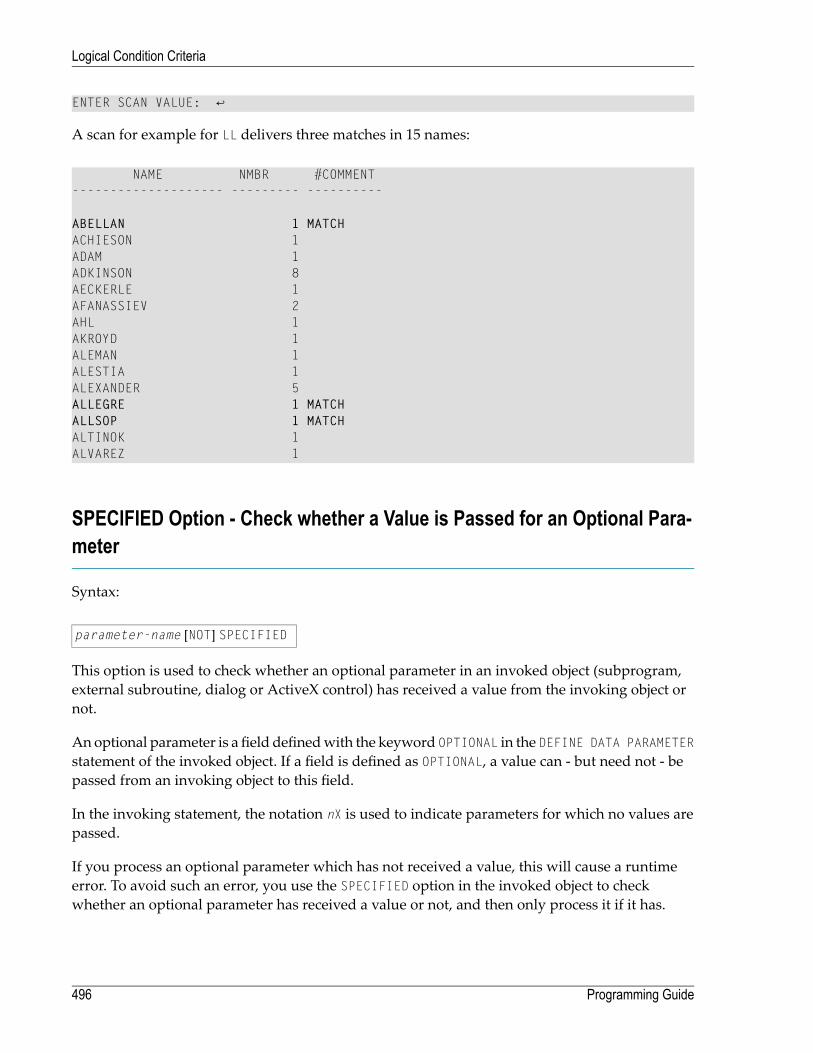
ENTER SCAN VALUE: ↩
A scan for example for LL delivers three matches in 15 names:
NAME NMBR #COMMENT-------------------- --------- ----------
ABELLAN 1 MATCHACHIESON 1ADAM 1ADKINSON 8AECKERLE 1AFANASSIEV 2AHL 1AKROYD 1ALEMAN 1ALESTIA 1ALEXANDER 5ALLEGRE 1 MATCHALLSOP 1 MATCHALTINOK 1ALVAREZ 1
SPECIFIED Option - Check whether a Value is Passed for an Optional Para-meter
Syntax:
parameter-name [NOT] SPECIFIED
This option is used to check whether an optional parameter in an invoked object (subprogram,external subroutine, dialog or ActiveX control) has received a value from the invoking object ornot.
An optional parameter is a field definedwith the keyword OPTIONAL in the DEFINE DATA PARAMETERstatement of the invoked object. If a field is defined as OPTIONAL, a value can - but need not - bepassed from an invoking object to this field.
In the invoking statement, the notation nX is used to indicate parameters for which no values arepassed.
If you process an optional parameter which has not received a value, this will cause a runtimeerror. To avoid such an error, you use the SPECIFIED option in the invoked object to checkwhether an optional parameter has received a value or not, and then only process it if it has.
Programming Guide496
Logical Condition Criteria
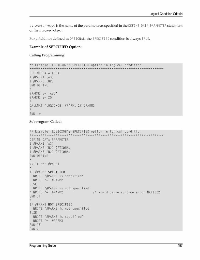
parameter-name is the name of the parameter as specified in the DEFINE DATA PARAMETER statementof the invoked object.
For a field not defined as OPTIONAL, the SPECIFIED condition is always TRUE.
Example of SPECIFIED Option:
Calling Programming:
** Example 'LOGICX07': SPECIFIED option in logical condition************************************************************************DEFINE DATA LOCAL1 #PARM1 (A3)1 #PARM3 (N2)END-DEFINE*#PARM1 := 'ABC'#PARM3 := 20*CALLNAT 'LOGICX08' #PARM1 1X #PARM3 * END ↩
Subprogram Called:
** Example 'LOGICX08': SPECIFIED option in logical condition************************************************************************DEFINE DATA PARAMETER1 #PARM1 (A3)1 #PARM2 (N2) OPTIONAL1 #PARM3 (N2) OPTIONALEND-DEFINE*WRITE '=' #PARM1*IF #PARM2 SPECIFIED
WRITE '#PARM2 is specified'WRITE '=' #PARM2
ELSEWRITE '#PARM2 is not specified'
* WRITE '=' #PARM2 /* would cause runtime error NAT1322END-IF*IF #PARM3 NOT SPECIFIED WRITE '#PARM3 is not specified'ELSE WRITE '#PARM3 is specified' WRITE '=' #PARM3 END-IF END ↩
497Programming Guide
Logical Condition Criteria

Output of Program LOGICX07:
Page 1 04-12-15 11:25:41
#PARM1: ABC#PARM2 is not specified#PARM3 is specified#PARM3: 20
Programming Guide498
Logical Condition Criteria
50 Rules for Arithmetic Assignment
■ Field Initialization ........................................................................................................................... 500■ Data Transfer ................................................................................................................................ 500■ Field Truncation and Field Rounding .................................................................................................. 503■ Result Format and Length in Arithmetic Operations .............................................................................. 503■ Arithmetic Operations with Floating-Point Numbers .............................................................................. 504■ Arithmetic Operations with Date and Time .......................................................................................... 506■ Performance Considerations for Mixed Format Expressions ................................................................... 510■ Precision of Results of Arithmetic Operations ...................................................................................... 510■ Error Conditions in Arithmetic Operations ........................................................................................... 511■ Processing of Arrays ...................................................................................................................... 512
499
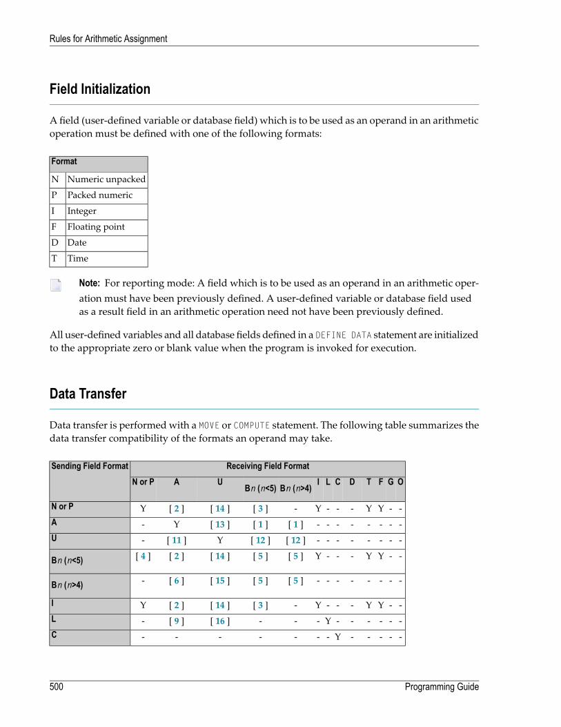
Field Initialization
Afield (user-defined variable or database field) which is to be used as an operand in an arithmeticoperation must be defined with one of the following formats:
Format
Numeric unpackedN
Packed numericP
IntegerI
Floating pointF
DateD
TimeT
Note: For reporting mode: A field which is to be used as an operand in an arithmetic oper-ation must have been previously defined. A user-defined variable or database field usedas a result field in an arithmetic operation need not have been previously defined.
All user-defined variables and all database fields defined in a DEFINE DATA statement are initializedto the appropriate zero or blank value when the program is invoked for execution.
Data Transfer
Data transfer is performedwith a MOVE or COMPUTE statement. The following table summarizes thedata transfer compatibility of the formats an operand may take.
Receiving Field FormatSending Field FormatOGFTDCLIBn (n>4)Bn (n<5)UAN or P
--YY---Y-[ 3 ][ 14 ][ 2 ]YN or P
--------[ 1 ][ 1 ][ 13 ]Y-A
--------[ 12 ][ 12 ]Y[ 11 ]-U
--YY---Y[ 5 ][ 5 ][ 14 ][ 2 ][ 4 ]Bn (n<5)
--------[ 5 ][ 5 ][ 15 ][ 6 ]-Bn (n>4)
--YY---Y-[ 3 ][ 14 ][ 2 ]YI
------Y---[ 16 ][ 9 ]-L
-----Y-------C
Programming Guide500
Rules for Arithmetic Assignment

--Y[7]Y--Y-Y[ 16 ][ 9 ]YD
--YY[ 8 ]--Y-Y[ 16 ][ 9 ]YT
--YY---Y-[ 3 ][ 10 ] [ 16 ][ 9 ] [ 10 ]YF
-Y-----------G
Y------------O
Where:
Indicates data transfer compatibility.Y
Indicates data transfer incompatibility.-
Numbers in brackets [ ] refer to the corresponding rule for data transfer given below.[ ]
Data Conversion
The following rules apply to converting data values:
1. Alphanumeric to binary:The value will be moved byte by byte from left to right. The result may be truncated or paddedwith trailing blank characters depending on the length defined and the number of bytes specified.
2. (N,P,I) and binary (length 1-4) to alphanumeric:The value will be converted to unpacked form and moved into the alphanumeric field left jus-tified, that is, leading zeros will be suppressed and the field will be filled with trailing blankcharacters. For negative numeric values, the sign will be converted to the hexadecimal notationDx. Any decimal point in the numeric value will be ignored. All digits before and after thedecimal point will be treated as one integer value.
3. (N,P,I,F) to binary (1-4 bytes):The numeric value will be converted to binary (4 bytes). Any decimal point in the numericvalue will be ignored (the digits of the value before and after the decimal point will be treatedas an integer value). The resulting binary number will be positive or a two's complement of thenumber depending on the sign of the value.
4. Binary (1-4 bytes) to numeric:The value will be converted and assigned to the numeric value right justified, that is, withleading zeros. (Binary values of the length 1-3 bytes are always assumed to have a positive sign.For binary values of 4 bytes, the leftmost bit determines the sign of the number: 1=negative,0=positive.) Any decimal point in the receiving numeric value will be ignored. All digits beforeand after the decimal point will be treated as one integer value.
5. Binary to binary:The value will be moved from right to left byte by byte. Leading binary zeros will be insertedinto the receiving field.
501Programming Guide
Rules for Arithmetic Assignment

6. Binary (>4 bytes) to alphanumeric:The value will be moved byte by byte from left to right. The result may be truncated or paddedwith trailing blanks depending on the length defined and the number of bytes specified.
7. Date (D) to time (T):If date is moved to time, it is converted to time assuming time 00:00:00:0.
8. Time (T) to date (D):If time is moved to date, the time information is truncated, leaving only the date information.
9. L,D,T,F to A:The values are converted to display form and are assigned left justified.
10. F:If F is assigned to an alphanumeric or Unicode field which is too short, the mantissa is reducedaccordingly.
11.Unicode to alphanumeric:The Unicode value will be converted to alphanumeric character codes according to the defaultcode page (value of the system variable *CODEPAGE) using the International Components forUnicode (ICU) library. The result may be truncated or padded with trailing blank characters,depending on the length defined and the number of bytes specified.
12.Unicode to binary:The value will be moved code unit by code unit from left to right. The result may be truncatedor padded with trailing blank characters, depending on the length defined and the number ofbytes specified. The length of the receiving binary field must be even.
13.Alphanumeric to Unicode:The alphanumeric value will be converted from the default code page to a Unicode value usingthe International Components for Unicode (ICU) library. The resultmay be truncated or paddedwith trailing blank characters, depending on the length defined and the number of code unitsspecified.
14. (N,P,I) and binary (length 1-4) to Unicode:The value will be converted to unpacked form from which an alphanumeric value will be ob-tained by suppression of leading zeros. For negative numeric values, the sign will be convertedto the hexadecimal notation Dx. Any decimal point in the numeric value will be ignored. Alldigits before and after the decimal pointwill be treated as one integer value. The resulting valuewill be converted from alphanumeric to Unicode. The result may be truncated or padded withtrailing blank characters, depending on the length defined and the number of codeunits specified.
15. Binary (>4 bytes) to Unicode:The value will be moved byte by byte from left to right. The result may be truncated or paddedwith trailing blanks, depending on the length defined and the number of bytes specified. Thelength of the sending binary field must be even.
Programming Guide502
Rules for Arithmetic Assignment

16. L,D,T,F to U:The values are converted to an alphanumeric display form. The resulting valuewill be convertedfrom alphanumeric to Unicode and assigned left justified.
If source and target format are identical, the result may be truncated or paddedwith trailing blankcharacters (format A and U) or leading binary zeros (format B) depending on the length definedand the number of bytes (format A and B) or code units (format U) specified.
See also Using Dynamic Variables.
Field Truncation and Field Rounding
The following rules apply to field truncation and rounding:
■ High-order numeric field truncation is allowed only when the digits to be truncated are leadingzeros. Digits following an expressed or implied decimal point may be truncated.
■ Trailing positions of an alphanumeric field may be truncated.■ If the option ROUNDED is specified, the last position of the result will be rounded up if the firsttruncated decimal position of the value being assigned contains a value greater than or equalto 5. For the result precision of a division, see alsoPrecision of Results of ArithmeticOperations.
Result Format and Length in Arithmetic Operations
The following table shows the format and length of the result of an arithmetic operation:
F8F4N or PI4I2I1
F8F4P*I4I2I1I1
F8F4P*I4I2I2I2
F8F4P*I4I4I4I4
F8F4P*P*P*P*N or P
F8F4F4F4F4F4F4
F8F8F8F8F8F8F8
On a mainframe computer, format/length F8 is used instead of F4 for improved precision of theresults of an arithmetic operation.
P* is determined from the integer length and precision of the operands individually for each oper-ation, as shown under Precision of Results of Arithmetic Operations.
The following decimal integer lengths and possible values are applicable for format I:
503Programming Guide
Rules for Arithmetic Assignment

Possible ValuesDecimal Integer LengthFormat/Length
-128 to 1273I1
-32768 to 327675I2
-2147483648 to 214748364710I4
Arithmetic Operations with Floating-Point Numbers
The following topics are covered below:
■ General Considerations■ Precision of Floating-Point Numbers■ Conversion to Floating-Point Representation■ Platform Dependency
General Considerations
Floating-point numbers (format F) are represented as a sum of powers of two (as are integernumbers (format I)), whereas unpacked and packed numbers (formats N and P) are representedas a sum of powers of ten.
In unpacked or packed numbers, the position of the decimal point is fixed. In floating-pointnumbers, however, the position of the decimal point (as the name indicates) is “floating”, that is,its position is not fixed, but depends on the actual value.
Floating-point numbers are essential for the computing of trigonometric functions ormathematicalfunctions such as sinus or logarithm.
Precision of Floating-Point Numbers
Due to the nature of floating-point numbers, their precision is limited:
■ For a variable of format/length F4, the precision is limited to approximately 7 digits.■ For a variable of format/length F8, the precision is limited to approximately 15 digits.
Valueswhich havemore significant digits cannot be represented exactly as a floating-point number.Nomatter howmany additional digits there are before or after the decimal point, a floating-pointnumber can cover only the leading 7 or 15 digits respectively.
An integer value can only be represented exactly in a variable of format/length F4 if its absolutevalue does not exceed 2 23 -1.
Programming Guide504
Rules for Arithmetic Assignment

Conversion to Floating-Point Representation
When an alphanumeric, unpackednumeric or packednumeric value is converted to floating-pointformat (for example, in an assignment operation), the representation has to be changed, that is, asum of powers of ten has to be converted to a sum of powers of two.
Consequently, only numbers that are representable as a finite sum of powers of two can be repres-ented exactly; all other numbers can only be represented approximately.
Examples:
This number has an exact floating-point representation:
1.25 = 20 + 2-2
This number is a periodic floating-point number without an exact representation:
1.2 = 20 + 2-3 + 2-4 + 2-7 + 2-8 + 2-11 + 2-12 + ...
Thus, the conversion of alphanumeric, unpacked numeric or packed numeric values to floating-point values, and vice versa, can introduce small errors.
Platform Dependency
Because of different hardware architecture, the representation of floating-point numbers variesaccording to platforms. This explains why the same application, when run on different platforms,may return slightly different results when floating-point arithmetics are involved. The respectiverepresentation also determines the range of possible values for floating-point variables, which is(approximately)
■ ±1.17 * 10-38 to ±3.40 * 1038 for F4 variables,■ ±2.22 * 10-308 to ±1.79 * 10308 for F8 variables.
Note: The representation used by your pocket calculator may also be different from theone used by your computer - which explains why results for the same computation maydiffer.
505Programming Guide
Rules for Arithmetic Assignment
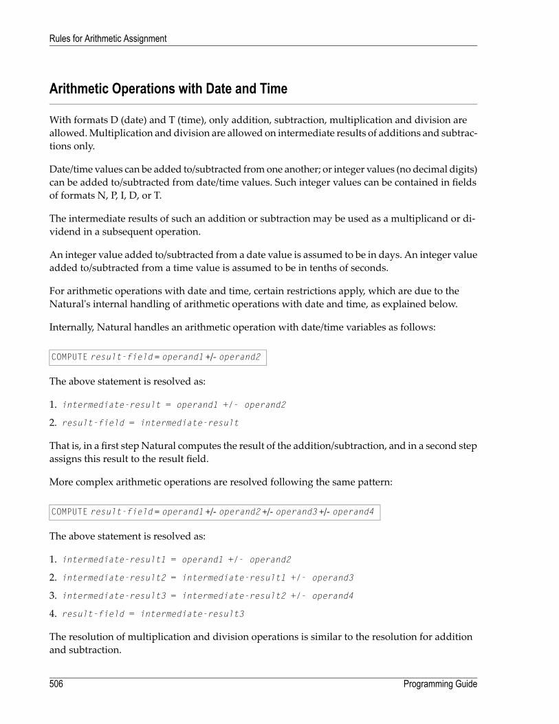
Arithmetic Operations with Date and Time
With formats D (date) and T (time), only addition, subtraction, multiplication and division areallowed.Multiplication and division are allowed on intermediate results of additions and subtrac-tions only.
Date/time values can be added to/subtracted fromone another; or integer values (no decimal digits)can be added to/subtracted from date/time values. Such integer values can be contained in fieldsof formats N, P, I, D, or T.
The intermediate results of such an addition or subtraction may be used as a multiplicand or di-vidend in a subsequent operation.
An integer value added to/subtracted from a date value is assumed to be in days. An integer valueadded to/subtracted from a time value is assumed to be in tenths of seconds.
For arithmetic operations with date and time, certain restrictions apply, which are due to theNatural's internal handling of arithmetic operations with date and time, as explained below.
Internally, Natural handles an arithmetic operation with date/time variables as follows:
COMPUTE result-field = operand1 +/- operand2
The above statement is resolved as:
1. intermediate-result = operand1 +/- operand2
2. result-field = intermediate-result
That is, in a first stepNatural computes the result of the addition/subtraction, and in a second stepassigns this result to the result field.
More complex arithmetic operations are resolved following the same pattern:
COMPUTE result-field = operand1 +/- operand2 +/- operand3 +/- operand4
The above statement is resolved as:
1. intermediate-result1 = operand1 +/- operand2
2. intermediate-result2 = intermediate-result1 +/- operand3
3. intermediate-result3 = intermediate-result2 +/- operand4
4. result-field = intermediate-result3
The resolution of multiplication and division operations is similar to the resolution for additionand subtraction.
Programming Guide506
Rules for Arithmetic Assignment

The internal format of such an intermediate result depends on the formats of the operands, asshown in the tables below.
Addition
The following table shows the format of the intermediate result of an addition(intermediate-result = operand1 + operand2):
Format of intermediate-resultFormat of operand2Format of operand1
DiDD
TTD
DDi, Ti, N, P, ID
TD, T, Di, Ti, N, P, IT
DDDi, Ti, N, P, I
TTDi, Ti, N, P, I
DiDiDi, N, P, I
TiTiTi, N, P, I
DiTi, N, P, IDi
TiDi, N, P, ITi
Subtraction
The following table shows the format of the intermediate result of a subtraction(intermediate-result = operand1 - operand2):
Format of intermediate-resultFormat of operand2Format of operand1
DiDD
TiTD
DDi, Ti, N, P, ID
TiD, TT
TDi, Ti, N, P, IT
DiDDi, N, P, I
TiTDi, N, P, I
DiDi, Ti, N, P, IDi
TiD, T, Di, Ti, N, P, ITi
P12Di, TiN, P, I
507Programming Guide
Rules for Arithmetic Assignment
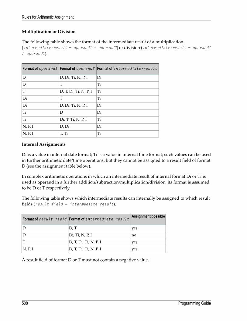
Multiplication or Division
The following table shows the format of the intermediate result of a multiplication(intermediate-result = operand1 * operand2) or division (intermediate-result = operand1/ operand2):
Format of intermediate-resultFormat of operand2Format of operand1
DiD, Di, Ti, N, P, ID
TiTD
TiD, T, Di, Ti, N, P, IT
TiTDi
DiD, Di, Ti, N, P, IDi
DiDTi
TiDi, T, Ti, N, P, ITi
DiD, DiN, P, I
TiT, TiN, P, I
Internal Assignments
Di is a value in internal date format; Ti is a value in internal time format; such values can be usedin further arithmetic date/time operations, but they cannot be assigned to a result field of formatD (see the assignment table below).
In complex arithmetic operations in which an intermediate result of internal format Di or Ti isused as operand in a further addition/subtraction/multiplication/division, its format is assumedto be D or T respectively.
The following table shows which intermediate results can internally be assigned to which resultfields (result-field = intermediate-result).
Assignment possibleFormat of intermediate-resultFormat of result-field
yesD, TD
noDi, Ti, N, P, ID
yesD, T, Di, Ti, N, P, IT
yesD, T, Di, Ti, N, P, IN, P, I
A result field of format D or T must not contain a negative value.
Programming Guide508
Rules for Arithmetic Assignment

Examples 1 and 2 (invalid):
COMPUTE DATE1 (D) = DATE2 (D) + DATE3 (D)COMPUTE DATE1 (D) = DATE2 (D) - DATE3 (D)
These operations are not possible, because the intermediate result of the addition/subtractionwould be format Di, and a value of format Di cannot be assigned to a result field of format D.
Examples 3 and 4 (invalid):
COMPUTE DATE1 (D) = TIME2 (T) - TIME3 (T)COMPUTE DATE1 (D) = DATE2 (D) - TIME3 (T)
These operations are not possible, because the intermediate result of the addition/subtractionwould be format Ti, and a value of format Ti cannot be assigned to a result field of format D.
Example 5 (valid):
COMPUTE DATE1 (D) = DATE2 (D) - DATE3 (D) + TIME3 (T)
This operation is possible. First, DATE3 is subtracted from DATE2, giving an intermediate result offormat Di; then, this intermediate result is added to TIME3, giving an intermediate result of formatT; finally, this second intermediate result is assigned to the result field DATE1.
Examples 6 and 7 (invalid):
COMPUTE DATE1 (D) = DATE2 (D) + DATE3 (D) * 2COMPUTE TIME1 (T) = TIME2 (T) - TIME3 (T) / 3
These operations are not possible, because the attempted multiplication/division is performedwith date/time fields and not with intermediate results.
Example 8 (valid):
COMPUTE DATE1 (D) = DATE2 (D) + (DATE3(D) - DATE4 (D)) * 2
This operation is possible. First, DATE4 is subtracted from DATE3 giving an intermediate result offormat Di; then, this intermediate result is multiplied by two giving an intermediate result offormat Di; this intermediate result is added to DATE2 giving an intermediate result of format D;finally, this third intermediate result is assigned to the result field DATE1.
If a format T value is assigned to a format D field, you must ensure that the time value contains avalid date component.
509Programming Guide
Rules for Arithmetic Assignment

Performance Considerations for Mixed Format Expressions
When doing arithmetic operations, the choice of field formats has considerable impact on perform-ance:
For business arithmetic, only fields of format I (integer) should be used, if possible.
For scientific arithmetic, fields of format F (floating point) should be used, if possible.
In expressionswhere formats aremixed between numeric (N, P) and floating point (F), a conversionto floating point format is performed. This conversion results in considerable CPU load. Thereforeit is recommended to avoid mixed format expressions in arithmetic operations.
Precision of Results of Arithmetic Operations
Digits After Decimal PointDigits Before Decimal PointOperation
Fd or Sd (whichever is greater)Fi + 1 or Si + 1 (whichever is greater)Addition/Subtraction
Fd + Sd (maximum 7)Fi + Si + 2Multiplication
(see below)Fi + SdDivision
Fd15 - Fd (See Exception below)Exponentiation
FdFiSquare Root
- where:
First operandF
Second operandS
ResultR
Digits before decimal pointi
Digits after decimal pointd
Exception:
If the exponent has one or more digits after the decimal point, the exponentiation is internallycarried out in floating point format and the result will also have floating point format. See Arith-metic Operations with Floating-Point Numbers for further information.
Programming Guide510
Rules for Arithmetic Assignment
Digits after Decimal Point for Division Results
The precision of the result of a division depends whether a result field is available or not:
■ If a result field is available, the precision is: Fd or Rd (whichever is greater) *.■ If no result field is available, the precision is: Fd or Sd (whichever is greater) *.
* If the ROUNDED option is used, the precision of the result is internally increased by one digit beforethe result is actually rounded.
A result field is available (or assumed to be available) in a COMPUTE and DIVIDE statement, and ina logical condition in which the division is placed after the comparison operator (for example: IF#A = #B / #C THEN ...).
A result field is not (or assumed to be not) available in a logical condition in which the division isplaced before the comparison operator (for example: IF #B / #C = #A THEN ...).
Exception:
If both dividend and divisor are of integer format and at least one of them is a variable, the divisionresult is always of integer format (regardless of the precision of the result field and of whether theROUNDED option is used or not).
Precision of Results for Arithmetic Expressions
The precision of arithmetic expressions, for example: #A / (#B * #C) + #D * (#E - #F + #G),is derived by evaluating the results of the arithmetic operations in their processing order. Forfurther information on arithmetic expressions, see arithmetic-expression in the COMPUTE statementdescription.
Error Conditions in Arithmetic Operations
In an addition, subtraction, multiplication or division, an error occurs if the total number of digits(before and after the decimal point) of the result is greater than 31.
In an exponentiation, an error occurs in any of the following situations:
■ if the base is of packed format and either the result has over 16 digits or any intermediate resulthas over 15 digits;
■ if the base is of floating-point format and the result is greater than approximately 7 * 1075.
511Programming Guide
Rules for Arithmetic Assignment

Processing of Arrays
Generally, the following rules apply:
■ All scalar operations may be applied to array elements which consist of a single occurrence.■ If a variable is defined with a constant value (for example, #FIELD (I2) CONSTANT <8>), thevaluewill be assigned to the variable at compilation, and the variablewill be treated as a constant.This means that if such a variable is used in an array index, the dimension concerned has a def-inite number of occurrences.
■ If an assignment/comparison operation involves two arrays with a different number of dimen-sions, the “missing” dimension in the array with fewer dimensions is assumed to be (1:1).
Example: If #ARRAY1 (1:2) is assigned to #ARRAY2 (1:2,1:2), #ARRAY1 is assumed to be #ARRAY1(1:1,1:2).
The following topics are covered below:
■ Definitions of Array Dimensions■ Assignment Operations with Arrays■ Comparison Operations with Arrays■ Arithmetic Operations with Arrays
Definitions of Array Dimensions
The first, second and third dimensions of an array are defined as follows:
PropertiesNumber of Dimensions
#a3(3rd dim., 2nd dim., 1st dim.)3
#a2(2nd dim., 1st dim.)2
#a1(1st dim.)1
Assignment Operations with Arrays
If an array range is assigned to another array range, the assignment is performed element by ele-ment.
Example:
Programming Guide512
Rules for Arithmetic Assignment

DEFINE DATA LOCAL1 #ARRAY(I4/1:5) INIT <10,20,30,40,50>END-DEFINE*MOVE #ARRAY(2:4) TO #ARRAY(3:5)/* is identical to/* MOVE #ARRAY(2) TO #ARRAY(3)/* MOVE #ARRAY(3) TO #ARRAY(4)/* MOVE #ARRAY(4) TO #ARRAY(5)/*/* #ARRAY contains 10,20,20,20,20
If a single occurrence is assigned to an array range, each element of the range is filled with thevalue of the single occurrence. (For a mathematical function, each element of the range is filledwith the result of the function.)
Before an assignment operation is executed, the individual dimensions of the arrays involved arecomparedwith one another to check if theymeet one of the conditions listed below. The dimensionsare compared independently of one another; that is, the 1st dimension of the one array is comparedwith the 1st dimension of the other array, the 2nd dimension of the one array is compared withthe 2nd dimension of the other array, and the 3rd dimension of the one array is compared withthe 3rd dimension of the other array.
The assignment of values from one array to another is only allowed under one of the followingconditions:
■ The number of occurrences is the same for both dimensions compared.■ The number of occurrences is indefinite for both dimensions compared.■ The dimension that is assigned to another dimension consists of a single occurrence.
Example - Array Assignments:
The following program shows which array assignment operations are possible.
DEFINE DATA LOCAL 1 A1 (N1/1:8) 1 B1 (N1/1:8) 1 A2 (N1/1:8,1:8) 1 B2 (N1/1:8,1:8) 1 A3 (N1/1:8,1:8,1:8) 1 I (I2) INIT <4> 1 J (I2) INIT <8> 1 K (I2) CONST <8> END-DEFINE * COMPUTE A1(1:3) = B1(6:8) /* allowed COMPUTE A1(1:I) = B1(1:I) /* allowed COMPUTE A1(*) = B1(1:8) /* allowed COMPUTE A1(2:3) = B1(I:I+1) /* allowed
513Programming Guide
Rules for Arithmetic Assignment

COMPUTE A1(1) = B1(I) /* allowed COMPUTE A1(1:I) = B1(3) /* allowed COMPUTE A1(I:J) = B1(I+2) /* allowed COMPUTE A1(1:I) = B1(5:J) /* allowed COMPUTE A1(1:I) = B1(2) /* allowed COMPUTE A1(1:2) = B1(1:J) /* NOT ALLOWED ↩(NAT0631) COMPUTE A1(*) = B1(1:J) /* NOT ALLOWED ↩(NAT0631) COMPUTE A1(*) = B1(1:K) /* allowed COMPUTE A1(1:J) = B1(1:K) /* NOT ALLOWED ↩(NAT0631) * COMPUTE A1(*) = B2(1,*) /* allowed COMPUTE A1(1:3) = B2(1,I:I+2) /* allowed COMPUTE A1(1:3) = B2(1:3,1) /* NOT ALLOWED ↩(NAT0631) * COMPUTE A2(1,1:3) = B1(6:8) /* allowed COMPUTE A2(*,1:I) = B1(5:J) /* allowed COMPUTE A2(*,1) = B1(*) /* NOT ALLOWED ↩(NAT0631) COMPUTE A2(1:I,1) = B1(1:J) /* NOT ALLOWED ↩(NAT0631) COMPUTE A2(1:I,1:J) = B1(1:J) /* allowed * COMPUTE A2(1,I) = B2(1,1) /* allowed COMPUTE A2(1:I,1) = B2(1:I,2) /* allowed COMPUTE A2(1:2,1:8) = B2(I:I+1,*) /* allowed * COMPUTE A3(1,1,1:I) = B1(1) /* allowed COMPUTE A3(1,1,1:J) = B1(*) /* NOT ALLOWED ↩(NAT0631) COMPUTE A3(1,1,1:I) = B1(1:I) /* allowed COMPUTE A3(1,1:2,1:I) = B2(1,1:I) /* allowed COMPUTE A3(1,1,1:I) = B2(1:2,1:I) /* NOT ALLOWED ↩(NAT0631) END
Comparison Operations with Arrays
Generally, the following applies: if arrays with multiple dimensions are compared, the individualdimensions are handled independently of one another; that is, the 1st dimension of the one arrayis compared with the 1st dimension of the other array, the 2nd dimension of the one array iscompared with the 2nd dimension of the other array, and the 3rd dimension of the one array iscompared with the 3rd dimension of the other array.
The comparison of two array dimensions is only allowed under one of the following conditions:
■ The array dimensions compared with one another have the same number of occurrences.
Programming Guide514
Rules for Arithmetic Assignment

■ The array dimensions compared with one another have an indefinite number of occurrences.■ All array dimensions of one of the arrays involved are single occurrences.
Example - Array Comparisons:
The following program shows which array comparison operations are possible:
DEFINE DATA LOCAL1 A3 (N1/1:8,1:8,1:8)1 A2 (N1/1:8,1:8)
1 A1 (N1/1:8)1 I (I2) INIT <4>1 J (I2) INIT <8>1 K (I2) CONST <8>END-DEFINE*IF A2(1,1) = A1(1) THEN IGNORE END-IF /* allowedIF A2(1,1) = A1(I) THEN IGNORE END-IF /* allowedIF A2(1,*) = A1(1) THEN IGNORE END-IF /* allowedIF A2(1,*) = A1(I) THEN IGNORE END-IF /* allowedIF A2(1,*) = A1(*) THEN IGNORE END-IF /* allowedIF A2(1,*) = A1(I -3:I+4) THEN IGNORE END-IF /* allowedIF A2(1,5:J) = A1(1:I) THEN IGNORE END-IF /* allowedIF A2(1,*) = A1(1:I) THEN IGNORE END-IF /* NOT ALLOWED(NAT0629)IF A2(1,*) = A1(1:K) THEN IGNORE END-IF /* allowed*IF A2(1,1) = A2(1,1) THEN IGNORE END-IF /* allowedIF A2(1,1) = A2(1,I) THEN IGNORE END-IF /* allowedIF A2(1,*) = A2(1,1:8) THEN IGNORE END-IF /* allowedIF A2(1,*) = A2(I,I -3:I+4) THEN IGNORE END-IF /* allowedIF A2(1,1:I) = A2(1,I+1:J) THEN IGNORE END-IF /* allowedIF A2(1,1:I) = A2(1,I:I+1) THEN IGNORE END-IF /* NOT ALLOWED(NAT0629)IF A2(*,1) = A2(1,*) THEN IGNORE END-IF /* NOT ALLOWED(NAT0629)IF A2(1,1:I) = A1(2,1:K) THEN IGNORE END-IF /* NOT ALLOWED(NAT0629)*IF A3(1,1,*) = A2(1,*) THEN IGNORE END-IF /* allowedIF A3(1,1,*) = A2(1,I -3:I+4) THEN IGNORE END-IF /* allowedIF A3(1,*,I:J) = A2(*,1:I+1) THEN IGNORE END-IF /* allowedIF A3(1,*,I:J) = A2(*,I:J) THEN IGNORE END-IF /* allowedEND
When you compare two array ranges, note that the following two expressions lead to differentresults:
515Programming Guide
Rules for Arithmetic Assignment

#ARRAY1(*) NOT EQUAL #ARRAY2(*)NOT #ARRAY1(*) = #ARRAY2(*)
Example:
■ Condition A:
IF #ARRAY1(1:2) NOT EQUAL #ARRAY2(1:2)
This is equivalent to:
IF (#ARRAY1(1) NOT EQUAL #ARRAY2(1)) AND (#ARRAY1(2) NOT EQUAL #ARRAY2(2))
ConditionA is therefore true if the first occurrence of #ARRAY1 does not equal the first occurrenceof #ARRAY2 and the second occurrence of #ARRAY1 does not equal the second occurrence of#ARRAY2.
■ Condition B:
IF NOT #ARRAY1(1:2) = #ARRAY2(1:2)
This is equivalent to:
IF NOT (#ARRAY1(1)= #ARRAY2(1) AND #ARRAY1(2) = #ARRAY2(2))
This in turn is equivalent to:
IF (#ARRAY1(1) NOT EQUAL #ARRAY2(1)) OR (#ARRAY1(2) NOT EQUAL #ARRAY2(2))
Condition B is therefore true if either the first occurrence of #ARRAY1 does not equal the first oc-currence of #ARRAY2 or the second occurrence of #ARRAY1 does not equal the second occurrenceof #ARRAY2.
Arithmetic Operations with Arrays
A general rule about arithmetic operations with arrays is that the number of occurrences of thecorresponding dimensions must be equal.
The following illustrates this rule:
#c(2:3,2:4) := #a(3:4,1:3) + #b(3:5)
In other words:
Programming Guide516
Rules for Arithmetic Assignment

RangeNumber of OccurrencesDimension NumberArray
2:322nd#c
2:431st#c
3:422nd#a
1:331st#a
3:531st#b
The operation is performed element by element.
Note: An arithmetic operation of a different number of dimensions is allowed.
For the example above, the following operations are executed:
#c(2,2) := #a(3,1) + #b(3)
#c(2,3) := #a(3,2) + #b(4)
#c(2,4) := #a(3,3) + #b(5)
#c(3,2) := #a(4,1) + #b(3)
#c(3,3) := #a(4,2) + #b(4)
#c(3,4) := #a(4,3) + #b(5)
Below is a list of examples of how array ranges may be used in the following ways in arithmeticoperations (in COMPUTE, ADD or MULTIPLY statements). In examples 1-4, the number of occurrencesof the corresponding dimensions must be equal.
1. range + range = range.
The addition is performed element by element.
2. range * range = range.
The multiplication is performed element by element.
3. scalar + range = range.
The scalar is added to each element of the range.
4. range * scalar = range.
Each element of the range is multiplied by the scalar.
5. range + scalar = scalar.
Each element of the range is added to the scalar and the result is assigned to the scalar.
6. scalar * range = scalar2.
517Programming Guide
Rules for Arithmetic Assignment

The scalar is multiplied by each element of the array and the result is assigned to scalar2.
Since intermediate results will be generated for arithmetic operations as shown in the above ex-amples, the result of overlapping index ranges is computed element by element in an intermediateresult array and finally the intermediate result array is assigned to the result field.
Example:
DEFINE DATA LOCAL1 #ARRAY(I4/1:5) INIT <10,20,30,40,50>END-DEFINE
#ARRAY(3:5) := #ARRAY(2:4) + 1
/* A temporary array for the/* intermediate result values is/* generated implicitly: #temp(1:3)./* The following operations are/* performed internally:/* #temp(1) := #ARRAY(2) + 1/* #temp(2) := #ARRAY(3) + 1/* #temp(3) := #ARRAY(4) + 1/* #ARRAY(3:5) := #temp(1:3)/*/* #ARRAY contains 10,20,21,31,41
Programming Guide518
Rules for Arithmetic Assignment

51 Invoking Natural Subprograms from 3GL Programs
■ Passing Parameters from the 3GL Program to the Subprogram .............................................................. 520■ Example of Invoking a Natural Subprogram from a 3GL Program ............................................................ 521
519

Natural subprograms can be invoked from a programming object written in a 3rd generationprogramming language (3GL). The invoking program can bewritten in anyprogramming languagethat supports a standard CALL interface.
For this purpose, Natural provides the interface ncxr_callnat. The 3GL program invokes thisinterface with a specification of the name of the desired subprogram.
Note: Natural must have been activated beforehand; that is, the invoking 3GL programmust in turn have been invoked by a Natural object with a CALL statement.
The subprogram is executed as if it had been invoked from another Natural object with a CALLNATstatement.
When the processing of the subprogram stops (either with the END statement or with an ESCAPEROUTINE statement), control is returned to the 3GL program.
Passing Parameters from the 3GL Program to the Subprogram
Parameters can be passed from the invoking 3GLprogram to theNatural subprogram. For passingparameters, the same rules apply as for passing parameters with a CALL statement.
The 3GL program invokes the Natural interface ncxr_callnatwith four parameters:
■ The 1st parameter is the name of the Natural subprogram to be invoked.■ The 2nd parameter contains the number of parameters to be passed to the subprogram.■ The 3rd parameter contains the address of the table that contains the addresses of the parametersto be passed to the subprogram.
■ The 4th parameter contains the address of the table that contains the format/length specificationsof the parameters to be passed to the subprogram.
The sequence, format and length of the parameters in the invoking program must match exactlythe sequence, format and length of the fields in the DEFINE DATA PARAMETER statement of thesubprogram. The names of the fields in the invoking program and the invoked subprogram canbe different.
Programming Guide520
Invoking Natural Subprograms from 3GL Programs

Example of Invoking a Natural Subprogram from a 3GL Program
For an example of how to invoke aNatural subprogram from a 3GLprogram, refer to the followingsamples in the Natural root directory's subdirectory samples\sysexuex.
■ MY3GL.NSP (for the main program),■ MY3GLSUB.NSN (for the subprogram),■ MYC3GL.C (for the C function).
521Programming Guide
Invoking Natural Subprograms from 3GL Programs

522
52 Issuing Operating System Commands from within a
Natural Program■ Syntax ......................................................................................................................................... 524■ Parameters .................................................................................................................................. 524■ Parameter Options ......................................................................................................................... 524■ Return Codes ............................................................................................................................... 525■ Examples ..................................................................................................................................... 525
523

The Natural user exit SHCMD can be used to issue an operating system command from within aNatural program.
Syntax
CALL 'SHCMD' 'command' ['option']
Parameters
command is to be executed by the operating system. To execute commands (such as DIR fordirectory or DEL for delete) you have to specify the system command interpreter as well.
command
For more information, see Examples below.
option describes how the command should be executed. This parameter is optional. Thefollowing options are available:
option
■ ASYNCH
■ NOSCREENIO
■ SYNCH (default)
See Parameter Options below.
Parameter Options
The following parameter options are available:
DescriptionOption
Natural does not wait until the command is completely executed. This kind of processingis named asynchronous processing.
ASYNCH
This option is used to hide the output generated by the command. The hidden output isredirected to the null device.
NOSCREENIO
Naturalwaits until the command is completed. This kind of processing is named synchronousprocessing and is set by default.
SYNCH
Note: The options ASYNCH and SYNCHmay be not set at the same time.
Programming Guide524
Issuing Operating System Commands from within a Natural Program

Return Codes
The following return code values are available:
DescriptionReturn Code
Command successfully executed.0
Illegal SHCMD parameter specified.4
Operating-system-dependent error code.All other codes
Examples
Execute operating system command DIR to view a directory:
CALL 'SHCMD''CMD.EXE /C DIR'
Retrieve the return code by using the Natural function RET:
RESET rc (I4)CALL 'SHCMD''CMD.EXE /C DIR'rc = RET( 'SHCMD' ) /* retrieve return codeIF rc <> 0 THEN /* in case of an errorDISPLAY "Error occurred during SHCMD" /* display an error message
Execute a command which includes blanks within the command by enclosing the command withquotation marks.
The following example executes Microsoft Excel.
RESET #cmd (A253)MOVE '"C:\Program Files\Microsoft Office\Office\EXCEL.EXE"' to #cmdCALL "SHCMD" #cmd "ASYNCH"
In this case, parameter TQ (translate quotationmarks) has to be OFF, otherwise the quotationmarkshave been removed.
To be independent of the TQparameter, use the hexadecimalASCII code of quotationmarks (H'22')and append it at the beginning and the end of the command. The following example demonstratesthis:
525Programming Guide
Issuing Operating System Commands from within a Natural Program

RESET #cmd (A253)MOVE H'22' - "C:\Program Files\Microsoft Office\Office\EXCEL.EXE" - H'22' to #cmdCALL "SHCMD" #cmd "ASYNCH"
Programming Guide526
Issuing Operating System Commands from within a Natural Program
53 Statements for Internet and XML Access
■ Statements Available ...................................................................................................................... 528■ Further References ........................................................................................................................ 529
527

This chapter gives an overview of theNatural statements for internet and XML access and containsa list of further references. To take full advantage of these statements, a thorough knowledge ofthe underlying communication standards is required.
Statements Available
The following statements are available for internet and XML access:
■ REQUEST DOCUMENT■ PARSE XML
REQUEST DOCUMENT
This statement enables you to use the HTTP/HTTPS protocol.
The following is an example of how this statement can be used to access an externally-locateddocument:
REQUEST DOCUMENT FROM"http://bolsap1:5555/invoke/sap.demo/handle_RFC_XML_POST" WITH USER #User PASSWORD #PasswordDATANAME 'XMLData' VALUE #QueryxmlNAME 'repServerName' VALUE 'NT2'RETURN PAGE #ResultxmlRESPONSE #rc ↩
For further information, see REQUEST DOCUMENT in the Statements documentation.
PARSE XML
The PARSE XML statement allows you to parse XML documents from a Natural program.
For further information, see PARSE XML in the Statements documentation.
Programming Guide528
Statements for Internet and XML Access

Further References
Below is a list of resources that you may find useful.
■ Sample Programs■ Training Courses■ Useful Links
Sample Programs
In addition to the sample programs provided at the end of the description of each statement, somesample programs are included in the Natural library SYSEXV.
Training Courses
SoftwareAG's CorporateUniversity offers special training courses on this subject. See theCorporateUniversity offerings on Empower at https://empower.softwareag.com/.
Or, ask your local Software AG representative for the availability of special on-site training coursesat your location.
Useful Links
Below is a collection of links that may be of interest.
■ World Wide Web Consortium (W3C): http://www.w3.org/■ Extensible Markup Language (XML): http://www.w3.org/XML/■ HyperText Markup Language (HTML) Home Page: http://www.w3.org/MarkUp/■ W3 Schools: http://www.w3schools.com/
529Programming Guide
Statements for Internet and XML Access

530

VIII Portable Natural Generated Programs
531

532

54 Portable Natural Generated Programs
■ Compatibility ................................................................................................................................. 534■ Endian Mode Considerations ........................................................................................................... 534■ ENDIAN Parameter ........................................................................................................................ 535■ Transferring Natural Generated Programs .......................................................................................... 535■ Portable FILEDIR.SAG and Error Message Files .................................................................................. 537
533

As of Natural Version 5, Natural generated programs (GPs) are portable across UNIX, OpenVMSand Windows platforms.
Compatibility
As ofNatural Version 5, a sourcewhichwas cataloged on anyNatural-supportedUNIX,OpenVMSandWindows platform is executable with all of these Open Systems platforms without recompil-ation. This feature simplifies the deployment of applications across Open Systems platforms.
Natural applications generated with Natural Version 4 or Natural Version 3 can be executed withNatural Version 5 or above without cataloging the applications again (upward compatibility). Inthis case, the portable GP functionality is not available. To make use of the portable GP and otherimprovements, cataloging with Natural Version 5 or above is required.
Command processor GPs are not portable. The portable GP feature is not available for mainframeplatforms. This means that Natural GPs which are generated on mainframe computers are notexecutable onUNIX, OpenVMS andWindows platformswithout recompilation of the applicationand vice versa.
Endian Mode Considerations
AsofNatural Version 5,Natural acts as follows:Depending onwhichUNIX,OpenVMSorWindowsplatform it is running, Natural will consider the byte order inwhichmulti-byte numbers are storedin the GP. The two byte order modes are called “Little Endian” and “Big Endian”.
■ “Little Endian” means that the low-order byte of the number is stored in memory at the lowestaddress, and the high-order byte at the highest address (the little end comes first).
■ “Big Endian” means that the high-order byte of the number is stored in memory at the lowestaddress, and the low-order byte at the highest address (the big end comes first).
The UNIX, OpenVMS andWindows platforms use both endian modes: Intel processors and AXPcomputers have “Little Endian” byte order, other processors such asHP-UX, Sun Solaris, or RS6000use “Big Endian” mode.
Natural converts a portable GP automatically into the endian mode of the execution platform, ifnecessary. This endian conversion is not performed if the GP has been generated in the endianmode of the platform.
Programming Guide534
Portable Natural Generated Programs

ENDIAN Parameter
In order to increase execution performance of portable GPs, the profile parameter ENDIAN has beenintroduced. ENDIAN determines the endian mode in which a GP is generated during compilation:
The endian mode of the machine on which the GP is generated.DEFAULT
Big endian mode (high order byte first).BIG
Little endian mode (low order byte first).LITTLE
The values DEFAULT, BIG and LITTLE are alternatives whereby the default value is DEFAULT.
The ENDIANmode parameter may be set
■ as a profile parameter with the Natural Configuration Utility,■ as a start-up parameter,■ as a session parameter or with the GLOBALS command.
Transferring Natural Generated Programs
To make use of the portable GP on different platforms (UNIX, OpenVMS and Windows), thegenerated Natural objects must be transferred to the target platform or must be accessible fromthe target platform, for example, via NFS.
Using theNatural Object Handler is the recommendedway to distributeNatural generated objectsor even entireNatural applications. This is done by unloading the objects in the source environmentinto a work file, transferring the work file to the target environment and loading the objects fromthe work file.
To deploy your Natural generated objects across Open Systems platforms
1 Start the Natural Object Handler. Unload all necessary cataloged objects into a work file oftype PORTABLE.
Error messages, if needed, can also be unloaded to the work file.
Important: The specified work file type must be of type PORTABLE. PORTABLE performsan automatic endian conversion of a work file when it is transferred to a different ma-chine. See also the information on the work file type in the description of the DEFINEWORK FILE statement in the Statements documentation.
535Programming Guide
Portable Natural Generated Programs

2 Transfer the work file to the target environment. Depending on the transfer mechanism(network, CD, diskette, tape, email, download, etc.), the use of a compressed archive such asa ZIP file or encoding with UUENCODE/UUDECODE or similar may make sense. Copyingvia FTP requires binary transfer type.
Note: According to the transfer method used, it may be necessary to adjust the recordformat and attributes or block size of the transferred work file depending on the spe-cific target platform, before continuing with the load function. The work file shouldhave the same format and attributes on the target platform as a work file of the sametype that was generated on the target platform itself. Use operating system tools if anadaptation is necessary.
3 Start the Natural Object Handler in the target environment. Select PORTABLE as work file type.Load the Natural objects and error messages from the work file.
For more details on how to use the Natural Object Handler, refer to Object Handler in the Utilitiesdocumentation.
You can find more information about how to port an application from a Natural developmentworkstation to a Natural Runtime workstation in the section Porting Procedure Overview in theOperations documentation.
Beside the aforementioned preferredmethod, there are various otherways of “moving” or copyingsingle Natural generated objects or even entire libraries or parts thereof, using operating systemtools and different transfermethods. In all of these cases, tomake the objects executable byNatural,they have to be imported into the Natural system file FUSER so that the FILEDIR.SAG structure isadapted. For information on the FNAT or FUSER directory, see System Files FNAT and FUSER in theOperations documentation.
This can be done with either of the following methods:
■ Using the Import function of the SYSMAIN utility.■ Using the FTOUCH utility. This utility can be used without entering Natural.■ It is also possible to import files from theWindows Explorer to the Natural environment, usingdrag-and-drop or the menu commands Cut, Copy and Paste. This means, if you have access tothe Natural objects you want to import via the Windows Explorer, you can use drag-and-dropor Cut, Copy and Paste, and the FILEDIR.SAG file will be updated automatically. For moredetails on copying, moving and importing objects, seeManaging Natural Objects in the UsingNatural Studio documentation.
The same applies when direct access is possible from a target platform to the generated objects inthe source environment, for example, via NSF, network file server, etc. In this case, the objectshave to be imported, too.
Programming Guide536
Portable Natural Generated Programs

Portable FILEDIR.SAG and Error Message Files
As ofNatural Version 6.2, the file FILEDIR.SAG and the errormessage files are platform independ-ent. Hence, it is possible to share common FUSER system files among different Open Systemsplatforms. For example, it is possible to copy sets of Natural libraries from one Open Systemsplatform to another with operating system copy procedures. However, it is not recommended toshare FNAT system files. For more information about the portable FILEDIR.SAG, refer to PortableNatural System Files in the Operations documentation.
537Programming Guide
Portable Natural Generated Programs

538

IX Introduction to Event-Driven Programming
What is an Event-Driven Application?
GUI Development Environments
GUI Design Tips
Tasks Involved in Creating an Application
Tutorial
Basic Terminology
For detailed information on event-drivenprogramming, seeEvent-DrivenProgrammingTechniques.
539

540
55 What is an Event-Driven Application?
■ Introduction .................................................................................................................................. 542■ Program-Driven Applications ............................................................................................................ 543■ Event Driven Applications ................................................................................................................ 544■ What is Happening Here? ............................................................................................................... 545■ Writing Event-Driven Code .............................................................................................................. 545■ Components of an Event Driven Application ........................................................................................ 546
541

Introduction
Event-driven applications represent a new approach to development in addition to the program-driven approach. Natural offers you both. Event-driven programming allows the application tobe driven by input received through the graphical user interface.
In program-driven applications, the application controls the portions of code that execute - not anevent. Execution startswith the first line of executable code and follows a defined pathway throughthe application, calling additional programs as instructed in the predetermined sequence.
In event-driven programming, the user's action or a system event triggers the code attached tothat event. Thus, the order in which your code executes depends on which events occur, whichin turn depends on what the user does. This is the essence of graphical user interfaces and event-driven programming: The user is in charge, and the code responds. Even though event-drivenprogramming is possible in character-oriented interfaces, it is more common in graphical user in-terfaces.
Because you cannot predict what the user will do, your code must make a few assumptions whenit executes. For example, the application might assume that the user added text to an edit-areacontrol before pressing theOK button.
When you must make assumptions, you should try to structure your application so that these as-sumptions are always valid. For example, to ensure the user added text, you can disable the buttonand enable it only when the change event occurs for the edit area control.
Your code can trigger additional events as it performs certain operations. For example, movingthe slider in a scroll bar control triggers the change event.
The following diagrams illustrate the difference between program-driven and event-driven applic-ations.
Programming Guide542
What is an Event-Driven Application?

Program-Driven Applications
In typical program-driven applications, the following sequence of steps applies:
1. The program sends a screen to the terminal.
2. The user reacts by filling in the data fields.
3. The user then presses ENTER or a function key.
4. The program then decides whether or not the user's entries are valid.
If the data are valid, it processes the results until it reaches an END statement.
543Programming Guide
What is an Event-Driven Application?

Event Driven Applications
In typical event-driven applications, the following sequence of steps applies:
1. The user requests an action on the screen.
2. The event handler code reacts in the background according to the context.
3. If certain conditions are fulfilled, the executed event handler code triggers other Natural code(here: a subroutine) or returns control to the screen.
In the program-driven approach, the user interacts with the code through the ENTER and functionkeys, the user of an event-driven application triggers specific pieces of code (event handlers).Typically, an event-driven application is not executing any code when waiting for user input; inthe same situation, the program-driven application might be processing an INPUT statement.
Programming Guide544
What is an Event-Driven Application?

What is Happening Here?
Graphical user interface programs require you to write programs that react to isolated events ini-tiated by the user.
An event is an action recognized by a dialog or a dialog element. Event-driven applications executecode in response to an event. Each dialog or dialog element has a predefined set of events. If oneof these events occurs, Natural invokes the code in the associated event handler.
You decide if and how the dialogs and dialog elements in your application respond to a particularevent. When you want a program to respond to an event, you write event code for that event.
Writing Event-Driven Code
For each dialog or dialog element you create, Natural predefines a set of events to which yourprogram (event handler) can respond. It is easy to respond to events: dialogs and dialog elementshave the built-in ability to recognize user actions and execute the code associated with them.
You do not have to write code for all events. When you do want a dialog object to respond to anevent, you write event code that Natural executes in response to that event.
In a typical event-driven application, the following series of actions takes place:
■ A dialog or dialog element recognizes an action as an event. The action can be caused by theuser (such as a click or keystroke).
■ If there is event code corresponding to the event, it is executed.■ The application waits for the next event.
The event code youwrite to respond to events can perform calculations, get input, andmanipulateparts of the interface. Using Natural, you manipulate dialogs or dialog elements by changing thevalues of their attribute settings.
Caution: Avoid creating cascading events in your code caused by events occurring re-peatedly. For example, when the user drags the slider in the scroll-bar control, the currentSLIDER attribute setting is automatically changed and the change event is triggered. If thecode attached to the change event also changes the current SLIDER attribute setting, thenthe change event is triggered again, the current SLIDER attribute setting is again adjusted,the change event is once again triggered, and so on. At this rate, you quickly run out ofmemory.
545Programming Guide
What is an Event-Driven Application?
Components of an Event Driven Application
The following topics are covered below:
■ Dialogs■ Dialog Elements■ Attributes■ Event Handlers■ Data Areas - Global, Local, Parameter■ Inline Subroutines
Dialogs
The dialog is the central Natural object in an event-driven application. An event-driven applicationis started by running or executing the base dialog. This may open other dependent dialogs whenthe OPEN DIALOG statement is specified. As opposed to program-driven applications, these dialogsare usually modeless, that is, all open dialogs can be processed concurrently by the end user. Theapplication terminates when the base dialog is closed.
You create a dialog with the dialog editor. Just like the map editor, the dialog editor assembles aNatural object from the specification of the dialogwindow and its dialog elements, the global dataarea (GDA), the local data areas (LDAs), the parameter data areas (PDAs), the subroutines andthe specified event handler sections.
At runtime of the dialog, there is a difference between the runtime instance identified by the systemvariable *DIALOG-ID and theGUI instance (handle) of the dialogwindow (the default handle nameis #DLG$WINDOW).
Whenever youwant to workwithmore than one dialog in your application, youmust decide howthe base dialogwindow relates to the other dialogs. First you have to decidewhether the applicationshould be MDI (Multiple Document Interface) or not.
If you have opted for anMDI application, the base dialogmust be of the type “MDI framewindow”and the dependent dialogs must be of the type “MDI child window” and “Standard window”.
If you have opted for non-MDI, the application may contain only dialogs of the type “Standardwindow”.
Dialogs of type “Standard window” can have the styles “Popup”, “Modal” or “Dialog Box”.
Programming Guide546
What is an Event-Driven Application?

Dialog Elements
Almost all dialog elements are graphical elements inside a dialog that allow the end user to interactwith the event-driven application. After a dialog has been opened with the dialog editor and itsattributes have been set (see below), the programmer will go on to “draw” the dialog elementsinside the window; usually, this comprises a menu control, possibly a toolbar, and other elements,such as push-button controls, input-field controls.
“Drawing” a dialog element means that you select the type of dialog element from the dialog ed-itor's menu or toolbar, and use the mouse to place it at the desired location. It is also possible todefine a grid where the dialog elements can be placed more conveniently by aligning them to thegrid.
547Programming Guide
What is an Event-Driven Application?
Attributes
Attributes are the properties of dialogs and dialog elements. After creating a dialog or dialog ele-ment, you double-click with the mouse on it and the window with the corresponding attributesappears. You can then set the attributes to a value; if not, they remain at the system default value.The attributeswindowalso contains a push-button control that opens up the event handlerwindow.
Event Handlers
The event handlers represent the Natural code that is triggered when an event occurs. A clickevent occurs, for example, when the end user clicks on a push-button control. Inside the eventhandler window, you must first select the type of event from the list of events available for thedialog or dialog element (the one whose attributes have just been set). Then, the code window isenabled and Natural code can be entered.
Data Areas - Global, Local, Parameter
■ A global data area (GDA) is used to share data fields betweenNatural objects within the applic-ation. One GDA per application may be specified.
■ A local data area (LDA) contains the data fields private to the dialog.■ A parameter data area (PDA) is always present in dialogs. It is used to pass parameters to adialog in the OPEN DIALOG or SEND EVENT statements. In these statements, parameters are passedeither by specifying their name (WITH clause), or by listing parameters one after the other. Youcan use the dialog editor PDA window to type in your PDA in free-form style or to includePDAs defined externally.
Inline Subroutines
An inline subroutine defines standard code to be used for a frequently needed task called by anumber of event handlers. You access an inline subroutine window via the Inline Subroutinespush button control in the dialog window.
Programming Guide548
What is an Event-Driven Application?

56 GUI Development Environments
To understand the functions of Natural, you must first understand the environment in which itruns.
A graphical user interface (GUI) environment differs from a traditional mainframe environmentin at least two important ways:
■ Applications share screen space. ANatural application runs in a group of one ormorewindowsand rarely occupies the full screen.
■ Applications share computing time. An application cannot run continually, or if it does, it mustrun in the background.
UsingNatural, your applications share computing time and other resources (such as the clipboard).An event-driven application consists of dialogs and dialog elements that wait for a particular eventto happen.
While your application is waiting to execute an event, it remains on the desktop (unless the usercloses the application). In the meantime, the user can run other applications, resize windows, orcustomize system settings (such as color). However, your code is always present, ready to be ac-tivated when the user returns to your application.
549

550

57 GUI Design Tips
■ Introduction .................................................................................................................................. 552■ Do Your Research ......................................................................................................................... 552■ Screen Design .............................................................................................................................. 553■ Menu Design ................................................................................................................................ 554■ Color Usage ................................................................................................................................. 555■ Consistency Check ........................................................................................................................ 555
551
Introduction
Designing the screens for a GUI application requires different knowledge than designing the 3270screens for a mainframe. Why is it different?
It is different, because GUI applications put the users in control; these applications are non-modaland unstructured. The users choose the order in which they access windows, and fields withinthe windows. Traditional database applications often require the users to perform operations ina specific order; these applications are form-oriented and structured.
Designing a GUI screen is also different, because the GUI interface has different capabilities thana traditionalmainframe interface. You can designwindows that incorporate dialog elements, suchas push button controls and list box controls. As you design your GUI windows, which are calleddialogs in event-driven Natural, you define the font type and size of the text, the background andforeground colors, and the size of each window.
The following sections provide some tips for effective GUI design.
Do Your Research
■ Spend a few hours with your users before prototyping.
A couple of sessions with your users to iron out their needs, likes, and dislikes is enough to giveyou to a good basis for beginning your design.
■ Take some ideas from existing GUI designs.
Save time by not re-inventing the GUI. Try out other GUIs with an eye for what works andwhatdoes not. ConsistencywithinGUIs helps users learn to use new applications, improves efficiency,and reduces training costs. Get user feedback on existing GUI applications - listen to their likesand dislikes rather than develop a prototype that replicates the weaknesses of poor GUI design.
■ Develop your ideas on paper before spending time developing the application online.
It is faster for you to run through a number of screen design options for your main windowson paper before spending time to create multiple prototypes online. It is quicker than codingand you do not become attached to poor designs.
If you include your users in the development process, they can quickly comment about theirneeds and likes before the application is installed in the system. Try to use a paper prototypebefore reaching for the online development tool.
Programming Guide552
GUI Design Tips
Screen Design
■ Design multiple windows for related subject matter.
Unlike designing for 3270monitors, where you try tomaximize the number of fields per screen,GUI screens are better designed using subwindows. You can, for example, have the essentialfields in the main window, and all optional or supplemental information stored in one or moresubwindows. Subwindows can include choices, such as drop-down lists, for the user to browsethrough if they do not know the information to input into the main window. Messages andfield-dependent information are more effectively presented in supplemental windows than inthe main window.
■ Design clear, uncluttered windows.
Avoid cluttering your windows with more than three colors, multiple graphics, and a varietyof shapes. Balance your objects on the screen with lots of white space so users are not over-whelmed by variety and distracted by the presentation. Try to keep shapes and objects to aminimum and the number of colors low.
■ Design accessible, not overwhelming, windows.
Multiple fonts, font sizes, font types or families, and color schemes can overwhelm your users,making your application seem inaccessible to them. Use a maximum of three fonts, font sizes,and font types per window. Avoid using italics and serif fonts because they often break up onthe screen. Use color sparingly. Neutral colors are kindest to your users eyes. Though vibrantreds and greens are very eye-catching, remember that your users spend a lot of their dayworking in the windows you design.
■ Design for both keyboard and mouse use.
Some users prefer using the keyboard andmemorize the short cut commands, while other usersare more comfortable using the mouse. Each action should be accessible by both the mouse andthe keyboard.
■ Design the windows according to your users' needs.
Though it is tempting to create fabulous-looking screens with lots of functionality, if your usersdo not use it, it is of no value. Remember that you are designing the application for your usersto get a job done, not for you to experiment with all the functionality you have available. Firstfind out what your users need, then tailor your design to meet their needs. You design screenswith different purposes in different ways. If you want to prompt the user, you use a conversa-tional style; if you want the user to enter values from a form, you use a data-entry style.
553Programming Guide
GUI Design Tips

Conversational Screens
■ Design conversational screens with field prompts.
In a conversational-based style, users enter data from a conversation (travel reservations, forexample). Conversational-based styles, in which the user relies on the screen for prompting,can be rich with labels, hints, instructions, and even questions for the users to ask their clients.
Data-Entry Screens
■ Design data-entry screens with terse labels.
In a form-based style, users enter data from a form. Each line on the input screen must matcha line on the form - and the lines must be in the same order. To maintain a line-for-line corres-pondence, you can abbreviate labels. Headings and instructions are kept to a minimum. Theonly purpose of labels is to help users find their places again after interruptions.
Menu Design
The following three criteria are recommended for designing menus.
■ Organize menus using the conventions defined by the operating system on which your usersrun the application. Microsoft Windows, for example, recommends certain menus (File, Edit,andView, for example), options onmenus (Cut,Copy, andPaste on theEditmenu, for example),and a particular order of the menus on the menu bar (Help always appears at the right margin,for example).
■ Arrangemenus by frequency of use and decide this information through observation or usabilitytesting.
Anticipatewhether usage changes as users becomemore expert.Watch that this does not violateconventions established for the operating system.
■ Listmenu items alphabetically. Remember to follow the operating-system conventions and userrecommendations for frequency of using menu items.
Programming Guide554
GUI Design Tips

Color Usage
■ Be as conservative as possible with color.
Humans can remember the meaning of no more than five colors at a time, plus or minus two.■ Use color as an additional signal, not as the primary signal.
Using bright red text to warn a user is not enough; add a warning tone. Eight percent of allmales are red-green color-blind and may not notice the red text.
■ On charts, do not use colors without adding a secondary key (for example, a broken or solidunderline).
Users with black and white monitors must be able to understand the key without the benefit ofcolor. Also, most users do not have color printers.
Consistency Check
■ Be consistent throughout the application.
Do not change fonts, colors, or shapes for related subjects. For example, design all theOK buttonsin an application with the same shape, size, color, and font. If related objects are presented indifferent ways, users cannot use the visual clues, taking them longer to become comfortablewith the application. Present similar actions in a similar way, using the same font, color, andsize for related buttons.
■ Adopt a naming convention (and stick with it throughout the application).
While traditional programs tend to have one large program you modify for a name change,object-oriented programs have numerous pieces of event code that you must edit individuallyevery time you make a name change. When you design GUI applications, you must be muchmore rigorous about sticking to naming conventions. This avoids a lot of cleaning up time later.
555Programming Guide
GUI Design Tips

556
58 Tasks Involved in Creating an Application
There are a number of main tasks you perform to create an application in event-driven Natural.The order in which they are explained in this section is the typical order in which you performthem. However, this sequence is not inflexible. For example, you may very well test a dialog sev-eral times in the process of designing it, and you will no doubt save your work more often duringthe development process.
■ Decide whether your application is “Multiple Document Interface” or “Single Document Inter-face”.
■ Create one or more dialogs.■ Set the attributes of the dialog(s).■ Create and place dialog elements in the dialog(s).■ Set the attributes of the dialog elements.■ Define the tab order in each of the dialogs (from the Dialogmenu, choose Control Sequence).■ Save the dialog(s) to a name.■ Define the global data area.■ Define the local data area(s).■ Write event handler code for the dialog(s).■ Write inline subroutines for the dialog(s).■ Write event handler code for the dialog elements.■ Stow the dialog(s).■ Test (check and run) the dialog(s).■ Execute the application.
The tutorial in the next section introduces you to the most frequently performed tasks.
557

558

59 Tutorial
■ Creating a Dialog ........................................................................................................................... 560■ Assigning Attributes to the Dialog ...................................................................................................... 561■ Creating Dialog Elements Inside the Dialog ......................................................................................... 563■ Assigning Attributes to the Dialog Elements ........................................................................................ 565■ Creating the Application's Local Data Area .......................................................................................... 566■ Attaching Event Handler Code to the Dialog Element ............................................................................ 567■ Checking, Stowing and Running the Application ................................................................................... 568
559

This chapter is a simple tutorial that demonstrates how to add the components of an event-drivenapplication one after the other. The tutorial describes how to develop a small sample applicationconsisting of one dialog. The application you will create is a degressive depreciation calculator.
You can use this calculator, for example, to find out the value of your car by entering how muchthe car was worth when you bought it, how many years you have owned it, and the percentageby which the value of the car decreases each year.
You can save your application at any stage, allowing you to interrupt the tutorial and continue ata later time where you left.
To develop the sample application
1 Create a new dialog (represented by a window).
2 Assign the attributes to your dialog (decide the window's settings).
3 Create the dialog elements in the dialog (decide how the user can interact).
4 Assign the attributes to your dialog elements (decide attribute settings).
5 Create the application's local data area (define the variables that allow the event handler touse the end user's numeric input).
6 Attach event handler code to the dialog element (decide what happens at runtime when theuser interacts).
7 Check, stow and run the application.
Apart from creating the local data area, this is the minimal number of steps required to create anyevent-driven application.
The above steps are described in detail in the following topics:
Creating a Dialog
To create a new dialog
1 Invoke Natural.
2 From theObjectmenu, chooseNew > Dialog.
The Natural window displays the menus and the toolbar for the dialog editor. It displays anediting window called Untitled1 - Dialog. You can resize this editing window.
Programming Guide560
Tutorial
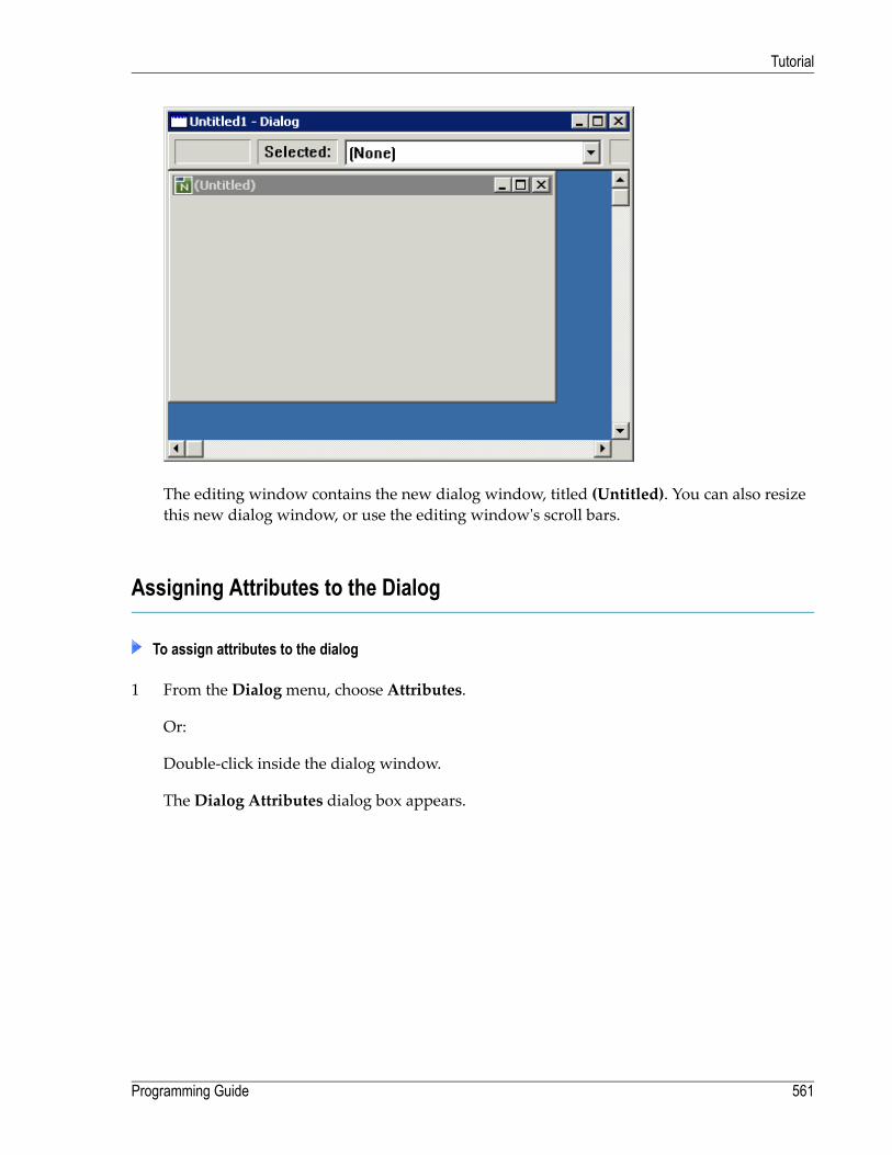
The editing window contains the new dialog window, titled (Untitled). You can also resizethis new dialog window, or use the editing window's scroll bars.
Assigning Attributes to the Dialog
To assign attributes to the dialog
1 From the Dialogmenu, choose Attributes.
Or:
Double-click inside the dialog window.
TheDialog Attributes dialog box appears.
561Programming Guide
Tutorial

2 With the cursor in the String text box, type in the new dialog window's title: DegressiveDepreciation.
3 From the Background color drop-down list box, select the desired color, for exampleGray.
4 Choose theOK button.
TheDialog Attributes dialog box closes.
You have set the attribute STRING to the value Degressive Depreciation and the attributeBACKGROUND-COLOUR-NAME to the value of your desired color, for example GRAY.
Programming Guide562
Tutorial
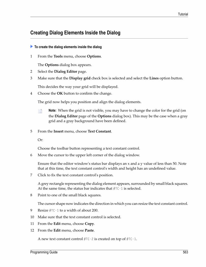
Creating Dialog Elements Inside the Dialog
To create the dialog elements inside the dialog
1 From the Toolsmenu, chooseOptions.
TheOptions dialog box appears.
2 Select the Dialog Editor page.
3 Make sure that the Display grid check box is selected and select the Lines option button.
This decides the way your grid will be displayed.
4 Choose theOK button to confirm the change.
The grid now helps you position and align the dialog elements.
Note: When the grid is not visible, you may have to change the color for the grid (onthe Dialog Editor page of theOptions dialog box). This may be the case when a graygrid and a gray background have been defined.
5 From the Insertmenu, choose Text Constant.
Or:
Choose the toolbar button representing a text constant control.
6 Move the cursor to the upper left corner of the dialog window.
Ensure that the editor window's status bar displays an x and a y value of less than 50. Notethat at this time, the text constant control's width and height has an undefined value.
7 Click to fix the text constant control's position.
A grey rectangle representing the dialog element appears, surrounded by small black squares.At the same time, the status bar indicates that #TC-1 is selected.
8 Point to one of the small black squares.
The cursor shape now indicates the direction inwhich you can resize the text constant control.
9 Resize #TC-1 to a width of about 200.
10 Make sure that the text constant control is selected.
11 From the Editmenu, choose Copy.
12 From the Editmenu, choose Paste.
A new text constant control #TC-2 is created on top of #TC-1.
563Programming Guide
Tutorial
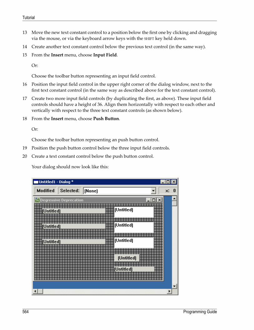
13 Move the new text constant control to a position below the first one by clicking and draggingvia the mouse, or via the keyboard arrow keys with the SHIFT key held down.
14 Create another text constant control below the previous text control (in the same way).
15 From the Insertmenu, choose Input Field.
Or:
Choose the toolbar button representing an input field control.
16 Position the input field control in the upper right corner of the dialog window, next to thefirst text constant control (in the same way as described above for the text constant control).
17 Create two more input field controls (by duplicating the first, as above). These input fieldcontrols should have a height of 36. Align them horizontally with respect to each other andvertically with respect to the three text constant controls (as shown below).
18 From the Insertmenu, choose Push Button.
Or:
Choose the toolbar button representing an push button control.
19 Position the push button control below the three input field controls.
20 Create a text constant control below the push button control.
Your dialog should now look like this:
Programming Guide564
Tutorial
Assigning Attributes to the Dialog Elements
To assign attributes to the dialog elements
1 Select the first text constant control #TC-1 and from the Controlmenu, choose Attributes.
Or:
Double-click the first text constant control #TC-1.
The corresponding attributes dialog box appears.
2 In the String text box, type in the text string to be displayed: Initial Value.
3 Choose theOK button.
The attributes dialog box closes.
4 Set the following text strings for the two text constant controls below:Number of Years for#TC-2 and Percentage Applicable for #TC-3.
5 From all three input field controls and from the fourth text constant control, remove any textstrings (that is, the Untitled strings).
6 Set the following text string for the push button control: Calculate.
Your dialog should now look like this:
565Programming Guide
Tutorial

Creating the Application's Local Data Area
The local data area in this application defines the application's linked variables. These linkedvariables receive the numeric values that the end user has entered in the input field controls. Thevariables and their values are used in the calculation of the push button control's click eventhandler code.
To prepare the creation of your local data area, your input field controls must use linked variables
1 Select the first input field control #IF-1 and from the Controlmenu, choose Attributes.
Or:
Double-click the first input field control #IF-1.
The corresponding attributes dialog box appears.
2 Choose the browse button (that is: the button with the three dots) to the right of the Stringtext box.
The Source for #IF-1.STRING dialog box appears.
3 Select (and enable) the Linked variable option button.
Programming Guide566
Tutorial
4 In the Variable name text box, enter: #INITIAL-VALUE.
5 Choose theOK button to close the Source for #IF-1.STRING dialog box and then choose theOK button to close the attributes dialog box.
6 Set the following linked variable names for the remaining two input field controls: #YEAR-NUMfor #IF-2 and #PERC-APPLIC for #IF-3.
To create the application's local data area
1 From the Dialogmenu, choose Local Data Area.
TheDialog Local Data Area dialog box appears.
2 Define your local data as follows:
1 #INITIAL-VALUE (N6.2)1 #PERC-APPLIC (N2.1)1 #YEAR-NUM (N2)
3 Choose theOK button.
Natural will now be able to process the input data.
Attaching Event Handler Code to the Dialog Element
To attach event handler code
1 Select the push button control labelled Calculate.
2 From the Controlmenu, select Event Handlers.
A dialog box for the corresponding event handler definition section appears.
The CLICK event is preselected: when the end user clicks on this push button control, thespecified Natural code will be triggered.
3 In the event handler editing area, enter the following Natural code in free form:
#RESULT:= #INITIAL-VALUE * ( ( ( 100 - #PERC-APPLIC )/ 100 ) ** #YEAR-NUM )MOVE EDITED #RESULT (EM=Z(5)9.99) TO #TC-4.STRING
4 Choose theOK button to close the dialog box.
567Programming Guide
Tutorial
Checking, Stowing and Running the Application
To check the application for syntax errors
1 From theObjectmenu, choose Check.
A dialog box comes up with a Natural error: a variable needs to be declared.
2 In the dialog box, choose the Edit button.
The dialog's code is displayed, the cursor pointing to the error (#RESULT).
3 Choose the Cancel button.
4 From the Dialogmenu, choose Local Data Area.
5 Add the following definition:
1 #RESULT (N6.2)
6 Choose theOK button.
7 Check your application again.
The information message box should now confirm that the check was successful.
To stow your application
1 From theObjectmenu, choose Stow.
The Stow Dialog As dialog box appears.
2 Enter the name Degrdep.
3 From the Libraries drop-down list box, select the library where you want the dialog to bestowed.
4 Choose theOK button.
The information message box now confirms that the dialog was stowed successfully.
To run your application
■ From theObjectmenu, choose Run.
Programming Guide568
Tutorial
60 Basic Terminology
■ Attribute ....................................................................................................................................... 570■ Base Dialog .................................................................................................................................. 570■ Control ........................................................................................................................................ 571■ Dialog ......................................................................................................................................... 571■ Dialog Box ................................................................................................................................... 571■ Dialog Editor ................................................................................................................................. 571■ Dialog Element .............................................................................................................................. 571■ Event .......................................................................................................................................... 572■ Event Handler ............................................................................................................................... 572■ Handle ........................................................................................................................................ 572■ Item ............................................................................................................................................ 572■ MDI - Multiple Document Interface .................................................................................................... 572■ MDI Child Window ......................................................................................................................... 573■ MDI Frame Window ....................................................................................................................... 573■ Modal Window .............................................................................................................................. 573■ SDI - Single Document Interface ....................................................................................................... 573■ Popup ......................................................................................................................................... 573■ Window ....................................................................................................................................... 573
569

Event-driven Natural uses the following basic terminology:
Attribute
A property of a dialog or a dialog element which can assume specific values.
Example: If the HAS-STATUS-BAR attribute is set to TRUE for a dialog, then the dialog contains astatus bar.
The following operations may be made on attributes:
ResultOperation
In event handler code, you can query an attribute's value at runtime. Example:Query
#L:= #DLG$WINDOW.HAS-STATUS-BAR
In event handler code, you can set an attribute to a value in the global attribute list before youcreate a dialog element dynamically. Example:
Set
#PUSH.STYLE:= 'O'PROCESS GUI ACTION ADD WITH #WPUSHBUTTON #PUSH
In event handler code, you canmodify an attribute value of an existing dialog element at runtime.Example:
Modify
#PUSH.STYLE:= 'C' ↩
Base Dialog
This is the main dialog of an application. It is started from the command line or via the object list.When this dialog is closed, all other dialogs of the application are closed as well.
Programming Guide570
Basic Terminology

Control
A type of dialog element. Examples: edit area control, push button control, list box control.
Dialog
A Natural object similar to a map or a program that represents a window in an event-driven ap-plication, plus all event handlers and attributes directly attached to thewindow. It can be awindow,a modal window, a dialog box, an MDI child window, and an MDI frame window. The windowas such is identified by its handle, the whole dialog is represented by the value of the systemvariable *DIALOG-ID.
Dialog Box
A special kind of dialog that is exclusively processed in an application. While this dialog is active,all other dialogs of the application are disabled and do not accept any user input. If a dialog invokesa dialog box with an OPEN DIALOG statement, the dialog returns from the OPEN DIALOG statementonly after the dialog box is closed. This allows the application to return parameters from the dialogbox to the dialog.
Dialog Editor
The Natural editor with which you create and maintain dialogs.
Dialog Element
Dialog elements are (in most cases) graphical elements inside a window that enable the end userto interact with the event-driven application. After a dialog has been created, and its attributeshave been set, the programmer places the dialog elements inside the window; usually, this com-prises a menu control, possibly a toolbar, and other elements, such as push button controls andinput field controls. There are two types of elements: controls and items.
571Programming Guide
Basic Terminology

Event
Occurs when a user interacts with a dialog element. An eventmay also be sent fromwithin a pieceof code (user-defined event). Example: a click event occurs when the user uses the mouse to clickon a push button control for which a piece of click event handler code has been specified. Thesystem variable *EVENT contains the event name.
Event Handler
Programming code that is connected with a dialog element, and is triggered when a particulartype of event occurs.
Handle
Identifies a dialog element in code and is stored in handle variables. Example: #PB-1.
Item
A type of dialog element that is part of a control. Example: selection box item, which is part of aselection box control.
MDI - Multiple Document Interface
Allows an application tomanage several different documents or several views of the samedocumentwithin themain applicationwindow (MDI framewindow). These views or documents are displayedin separate MDI child windows.
Programming Guide572
Basic Terminology

MDI Child Window
Displays a view of a document within the MDI frame window of an MDI application.
MDI Frame Window
The parent window to all other child (document) windows in an MDI application.
Modal Window
Similar to a dialog box, except that if a dialog invokes a modal window with an OPEN DIALOGstatement, the dialog returns from the OPEN DIALOG statement immediately after themodalwindowhas completed opening.
SDI - Single Document Interface
As opposed toMDI applications, SDI applications do not have anMDI framewindow that containsthe document windows. Only a single view of a single document is displayed.
Popup
A dialog with style Popup is modeless and can be moved anywhere on the desktop.
Window
The basic type of window.
573Programming Guide
Basic Terminology

574

X Event-Driven Programming Techniques
Introduction
How To Open and Close Dialogs
How To Edit a Dialog's Enhanced Source Code
How Dialogs, Controls and Items Are Related Hierarchically
How To Define Dialog Elements
How To Manipulate Dialog Elements
How To Create and Delete Dialog Elements Dynamically
How To Enable and Disable Dialog Elements
Defining and Using Context Menus
Using the Clipboard and Drag and Drop
Using the TERMINATE or STOP Statements within Dialog-based Applications
System Variables
Generated Variables
Message Files and Variables as Sources of Attribute Values
Triggering User-Defined Events
Suppressing Events
Menu Structures, Toolbars and the MDI
Executing Standardized Procedures
Linking Dialog Elements to Natural Variables
Validating Input in a Dialog Element
Storing and Retrieving Client Data for a Dialog Element
Creating Dialog Elements on a Canvas Control
Label Editing in Tree View and List View Controls
Working with ActiveX Controls
Working with Arrays of Dialog Elements
Working with Control Boxes
Working with Date and Time Picker (DTP) Controls
575

Working with Dialog Bar Controls
Working with Error Events
Working with a Group of Radio-Button Controls
Working with Image List Controls
Working with List Box Controls and Selection Box Controls
Working with List View Controls
Working with Nested Controls
Working with a Dynamic Information Line
Working with Spin Controls
Working with a Status Bar
Working with Status Bar Controls
Working with Tab Controls
Working with Tree View Controls
Working with Dynamic Information Line and Status Bar
Adding a Maximize/Minimize/System Button
Defining Color
Adding Text in a Certain Font
Adding Online Help
Defining Mnemonic and Accelerator Keys
Dynamic Data Exchange - DDE
Object Linking and Embedding - OLE
Programming Guide576
Event-Driven Programming Techniques

61 Introduction
This documentation addresses the more experienced GUI programmer and describes essentialprogramming techniques. There are two ways to program in the dialog editor:
■ Use the dialog editor's menu bar and toolbar to create new dialogs or dialog elements and usethe attributes window to assign attribute values to them. The dialog editor will internally gen-erate the corresponding Natural code.
■ Open an event-handler section or an inline-subroutine section and specifyNatural code explicitly.This code will be added to the code that is generated internally. You can also enter parameterdata areas, global data areas and local data areas in the corresponding definition sections.
You can view the current dialog's generated and specified code by choosingObject > List in thedialog editor's menu bar.
If you want a hands-on demonstration of how to program with the dialog editor, refer to the SY-SEXEVT library. This library contains sample dialogs demonstrating basic functionality. Beforeaccessing the sample dialogs, read the README file. Then execute the MENU dialog.
Note: Code written in the dialog editor must be in structured mode.
If you want to execute a Natural application using dialogs, you must use a dialog to start this ap-plication.
For further information on event-driven programming see Introduction to Event-Driven Program-ming.
577

578

62 How To Open and Close Dialogs
■ Opening a Dialog ........................................................................................................................... 580■ Operands ..................................................................................................................................... 580■ Passing Parameters to the Dialog ..................................................................................................... 581■ Permanence in Creating, Passing and Checking Data ........................................................................... 582■ Processing Steps When Opening a Dialog .......................................................................................... 583■ Closing Dialogs ............................................................................................................................. 584■ Initializing Attribute Values ............................................................................................................... 584
579

This chapter covers the following topics:
Opening a Dialog
An event-driven application is started by executing the base dialog. Events triggered by the enduser will then typically cause other dialogs to be started. The application ends when the basedialog is closed.
To open a dialog from anywhere within an event-driven application
■ Use the statement OPEN DIALOG.
This statement causes the dialog to be loaded and the processing on its opening to be performed.
Control over processing returns from the opened dialog except for dialogs with the style "DialogBox". For those dialog styles, control returns only after the dialog has ended.
The parameters passed are accessible only during the processing on the opening of a dialog (before-open and after-open events), except for when the parameters are declared as BY VALUE in theparameter data area of the opened dialog or when the dialog has the style "Dialog Box".
To open a dialog from anywherewithin an event-drivenNatural application, the following syntaxis used:
[PARENT] operand2[USING]OPEN DIALOG operand1
][DIALOG-ID] operand3[GIVING][
operand4...WITH
PARAMETERS-clause
Operands
Operand1 is the name of the dialog to be opened. If the PARAMETERS-clause is used, operand1mustbe a constant (the name of a cataloged dialog).
Operand2 is the handle name of the parent.
Operand3 is a unique dialog ID returned from the creation of the dialog. It must be defined withformat/length I4.
Programming Guide580
How To Open and Close Dialogs
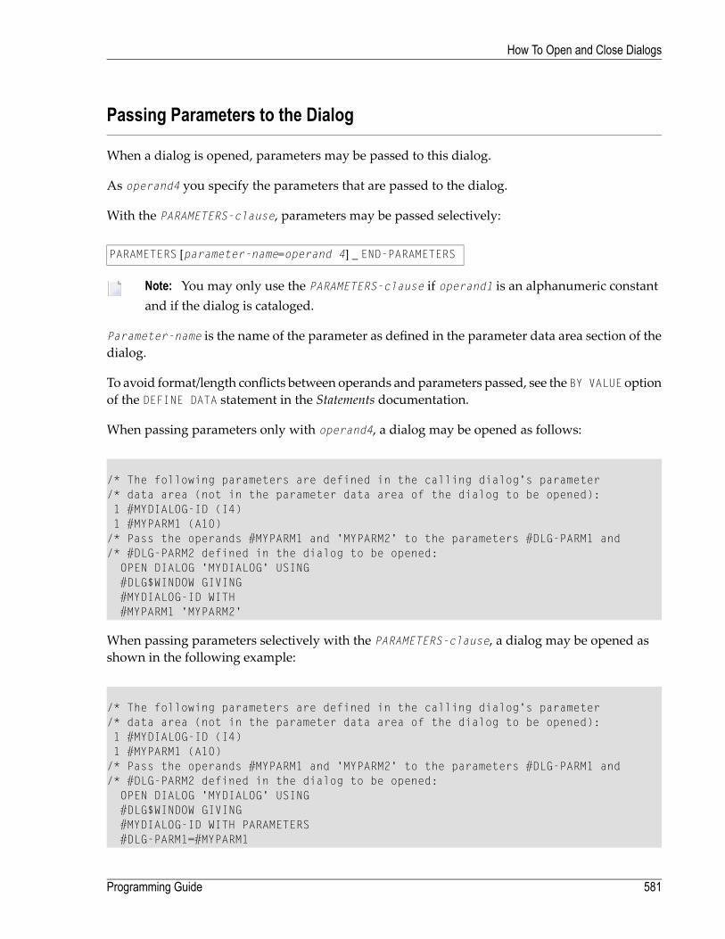
Passing Parameters to the Dialog
When a dialog is opened, parameters may be passed to this dialog.
As operand4 you specify the parameters that are passed to the dialog.
With the PARAMETERS-clause, parameters may be passed selectively:
PARAMETERS [parameter-name=operand 4] _ END-PARAMETERS
Note: You may only use the PARAMETERS-clause if operand1 is an alphanumeric constantand if the dialog is cataloged.
Parameter-name is the name of the parameter as defined in the parameter data area section of thedialog.
To avoid format/length conflicts between operands and parameters passed, see the BY VALUE optionof the DEFINE DATA statement in the Statements documentation.
When passing parameters only with operand4, a dialog may be opened as follows:
/* The following parameters are defined in the calling dialog's parameter/* data area (not in the parameter data area of the dialog to be opened):1 #MYDIALOG-ID (I4)1 #MYPARM1 (A10)/* Pass the operands #MYPARM1 and 'MYPARM2' to the parameters #DLG-PARM1 and/* #DLG-PARM2 defined in the dialog to be opened:
OPEN DIALOG 'MYDIALOG' USING#DLG$WINDOW GIVING#MYDIALOG-ID WITH#MYPARM1 'MYPARM2'
When passing parameters selectively with the PARAMETERS-clause, a dialog may be opened asshown in the following example:
/* The following parameters are defined in the calling dialog's parameter/* data area (not in the parameter data area of the dialog to be opened):1 #MYDIALOG-ID (I4)1 #MYPARM1 (A10)/* Pass the operands #MYPARM1 and 'MYPARM2' to the parameters #DLG-PARM1 and/* #DLG-PARM2 defined in the dialog to be opened:
OPEN DIALOG 'MYDIALOG' USING#DLG$WINDOW GIVING#MYDIALOG-ID WITH PARAMETERS#DLG-PARM1=#MYPARM1
581Programming Guide
How To Open and Close Dialogs

#DLG-PARM2='MYPARM2'END-PARAMETERS
Permanence in Creating, Passing and Checking Data
The term “permanence” is used inNatural to denote data defined in a base dialog's local data areawhose existence is guaranteed throughout the whole lifetime of the dialog. Data defined in theglobal data area are not kept permanent because the global data area can be exchanged while theapplication is executed.
The reference to the permanent data is kept by saving the parameter data area internally duringopening of the dialog. This reference is reused when
■ a dialog element receives an event;■ all parameters passed from one dialog to another are permanent, provided they reference thebase dialog's local data area.
Parameters are accessible
■ during the before-open and after-open event processing on opening of a dialog or■ if all of them reference the base dialog's local data area.
The following example illustrates a case in which two parameters are kept permanently and oneother is not. Assume the base dialog is dialog A. This base dialog now opens dialog B, passingparameters #X and #Y. After that, dialog B passes parameters #X and #Y on to dialog C. The #X and#Y parameterswhich are now in dialog Cwill be permanent, even if dialog B is closed. If, however,dialog B passes its own parameter #Zwhen opening dialog C, the parameter #Z is not permanent,because if dialog B is closed, the reference to its local data area is no longer valid. No parameterin dialog C is accessible (#Z does not reference the base dialog's local data area).
Programming Guide582
How To Open and Close Dialogs

Processing Steps When Opening a Dialog
This section describes what happens when a dialog is opening. You can open a dialog either byexecuting it, for example from the command line, or by invoking it with an OPEN DIALOG statement.
■ The dialog object is loaded and starts executing.■ The BEFORE-ANY event-handler section is executed, the value of the system variable *EVENT beingOPEN.
■ The BEFORE-OPEN event-handler section is executed.■ The dialog window is created as specified in the dialog editor.■ The BEFORE-ANY event-handler section is executed. *EVENT = AFTER-OPEN.■ All dialog elements are created as specified in the dialog editor.■ The dialog window and all dialogs are made visible except those that are VISIBLE = FALSE.■ The AFTER-OPEN event-handler section is executed.■ The AFTER-ANY event-handler section is executed. *EVENT = AFTER-OPEN.■ The AFTER-ANY event-handler section is executed. *EVENT = OPEN (not if the dialog's STYLE attributevalue is "Dialog Box").
583Programming Guide
How To Open and Close Dialogs

Closing Dialogs
To close a dialog dynamically, you specify the following:
operand1CLOSE DIALOG [USING] [DIALOG-ID]
*DIALOG-ID
Operand1 is the identifier of the dialog as returned in the OPEN DIALOG statement.
Example:
CLOSE DIALOG *DIALOG-ID /* Close the current Dialog
The dialogwill then be erased from the screen and removed frommemory. All local data associatedwith the dialog will be gone.
Note: If a modal dialog is a child in a hierarchy of dialogs, the modal dialog should notclose its parent(s) because this will result in a deadlock.
operand1
Operand1 is the name of the dialog to be closed.
To close the current dialog, you specify *DIALOG-ID.
Initializing Attribute Values
You can specify conditions for the opening and closing of a dialog: this applies to the before-open,after-open, and close events. These conditions can be used to initialize the attribute values in thedialog.
The following is an example of after-open event-handler code: Red foreground color is assignedto push buttons that the user must press after entering data in the associated input fields.
DEFINE DATA LOCAL...
1 #OK-BUTTON HANDLE OF PUSHBUTTON1 #CALC-BUTTON HANDLE OF PUSHBUTTON1 #SAVE-BUTTON HANDLE OF PUSHBUTTON1 #CONVERT-BUTTON
HANDLE OF PUSHBUTTON...
Programming Guide584
How To Open and Close Dialogs

END-DEFINE...#OK-BUTTON.FOREGROUND-COLOUR-NAME := RED#CALC-BUTTON.FOREGROUND-COLOUR-NAME := RED#SAVE-BUTTON.FOREGROUND-COLOUR-NAME := RED#CONVERT-BUTTON.FOREGROUND-COLOUR-NAME := RED
If you want to modify attribute values of dialog elements and of the dialog before the dialog isopened (and displayed to the end user), do not specify this in the "before open" event-handlercode, because the dialog elements and the dialog window are not yet created. Instead, create thedialog with the dialog editor and set the attribute VISIBLE to FALSE in the Dialog Attributeswindow. Then modify all the attribute values in the after-open event-handler code (when thehandles are available). Then make the dialog visible with VISIBLE = TRUE.
Example:
DEFINE DATA LOCAL...1 #DIA-1 HANDLE OF DIALOG1 #OK-BUTTON HANDLE OF PUSHBUTTON1 #CALC-BUTTON HANDLE OF PUSHBUTTON...END-DEFINE.../* AFTER OPEN event-handler code section...#OK-BUTTON.FOREGROUND-COLOUR-NAME := RED#CALC-BUTTON.FOREGROUND-COLOUR-NAME := RED#DIA-1.VISIBLE := TRUE
585Programming Guide
How To Open and Close Dialogs

586

63 How To Edit a Dialog's Enhanced Source Code
■ What Is The Enhanced Source Code Format? ..................................................................................... 588■ Avoiding Incompatibilities Between Dialog Editor And Program Editor ...................................................... 589■ How To Use The Enhanced Source Code Format ................................................................................. 590
587

What Is The Enhanced Source Code Format?
The enhanced source code format enables you to edit source code that has been generated by thedialog editor. You edit enhanced source code in a program editorwindow.When you edit a dialog,the dialog editor stores the results in internal structures. From these structures, source code isgenerated when you save, stow, list or execute any other system command on the dialog. Code isalso generated when you refresh the program editor's source code window.
You can edit enhanced source code as you do any other Natural user code. The source code syntaxis subject to a number of formal conventions, however. For a documentation of the enhancedsource code syntax, see Enhanced Source Code Format in the Dialog Editor part of the Editors docu-mentation.
When you execute a system command on a dialog you have just edited in the program editorsource code window, the dialog editor updates its internal structures and refreshes the sourcecode window.
Note: The dialog editor preserves code layout only in the user code sections, such as eventhandlers.
The dialog editor supports the following source formats:
■ 213. This is the format generated by Natural Version 2.1.3 (New Dimension). It is supported forinput only. You cannot generate 2.1.3 format with Natural Version 3.1 and Version 3.2.
■ 22C. This is the format generated by Natural Version 2.2.2. In Natural for Windows, Naturalfor UNIX and Natural for OpenVMS, dialogs can no longer be generated in this format. It, too,is supported for input only.
■ 22D. This is the “enhanced” source-code format that fromnowon is the standard. It is generatedfor compiling, storing, and editing dialogs in Natural Version 2.2.3 and above.
The characteristics of the enhanced source code format are:
■ Dialog sources are readable and printable without requiring conversion.■ Dialog sources consist only of legal and fully documented Natural syntax.■ Dialog sources can be edited textually using program editor functions such as scanning for andreplacing text.
■ Dialog sources can be displayed in the Natural Debugger.■ Dialog sources are larger than 213 or 22C format sources (by a factor between 1.25 and 3.5).■ Any code that can be generatedwith the dialog editor can also be codedmanually. For example,if you “draw” a push-button control onto the user interface, the corresponding code is generatedimplicitly. You can also create this push-button control explicitly with the help of a source-codewindow that provides you with the functions of the program editor.
Programming Guide588
How To Edit a Dialog's Enhanced Source Code

■ You can switch between the dialog editor and the program editor by selecting the source codewindow or the dialog window. If you edit in either window, you need to synchronize yourupdates: (graphically) modifying the dialog locks the source code window and you may notmake changes there. Correspondingly, if you change the source code, youmay notmake changesin the dialog window, which is locked. If your editor is locked, its status bar displays "Locked".
For dialogs in the old formats, this means:
■ They remain unchanged until they are processed in the dialog editor. They can be compiledand executed in their old format.
■ When you load them into the dialog editor, the dialogs are saved in the new format. If they aresaved in the enhanced format, you must include the local data area NGULKEY1. Note that thestorage size increases when the dialogs are saved.
■ When you list or print them and you enable the "enhanced list mode" option, the dialogs aredisplayed using the enhanced source code format.
Avoiding Incompatibilities Between Dialog Editor And Program Editor
When you edit the enhanced source code format, note that some of the syntax elements acceptedby the program editor are not accepted by the dialog editor. Enhanced source code editing is notintended as a new programming technique in addition to using the dialog editor:
■ Itmay be syntactically acceptable to replace a dialog element's numeric coordinate (a RECTANGLE-X attribute value) with a variable reference. The dialog editor, however, will not accept thiswhen the changes are synchronized, andwill prompt youwhen you issue a command requiringthe source code.
■ The dialog editor may accept a reference to a variable's STRING attribute even if the variable isnot declared, but the compiler will not accept this.
In the sections that are not user code, you should avoid such incompatibilities by adding onlycode that is acceptable to both the compiler and the dialog editor.
In the user code sections, such as in event-handler sections and in external or internal subroutines,your choice of programming techniques is not restricted by the dialog editor. In these sections,however, you have no visual editing support.
As a general rule, a mixed approach is often the best, especially when you use dialog-editor-generated code as a starting point.
Note: In the dialog editor, you can copy dialog elements to the clipboard and when youpaste them into user code, they appear as text.
589Programming Guide
How To Edit a Dialog's Enhanced Source Code

How To Use The Enhanced Source Code Format
To edit a dialog in the enhanced source code format
1 Load the dialog into the dialog editor.
2 From the Dialogmenu, choose Source Code.
Or:
Choose the "Source Code" toolbar button.
Or:
Press CTRL+ALT+C.
The dialog's source codewindowappears and the programeditor is loaded. This editor enablesyou to scan for text strings, replace them, and so on. For more information on how to use theprogram editor, refer to Program Editor.
The enhanced source code format's syntactical conventions are documented in the sectionEnhancedSource Code Format of the Dialog Editor part of the Editors documentation.
Enhanced source code can be listed and printed as usual. You can also scan for strings by usingthe Find command of the Editmenu.
Note: If you are replacing strings with this command, this canmake a dialog source incom-patible with the dialog editor.
Programming Guide590
How To Edit a Dialog's Enhanced Source Code

64 How Dialogs, Controls and Items Are Related
Hierarchically
Dialogs and their dialog elements are organized hierarchically. Typically, the dialog windowcontains a number of controls. The controls are children of the window or of other controls whichare capable of acting as containers. A control may contain a number of items. For example, a listbox control may contain several list box items. The control is the parent of the items.
The dialogs themselves are also organized hierarchically. Every time the OPEN DIALOG statementis specified, the parent of the newly created dialog must be provided as a parameter. This para-meter may be NULL-HANDLE or the handle of an existing dialog. If NULL-HANDLE is provided, thedialog belongs to the desktop rather than to any other dialog. This means that the dialog can beclosed and minimized independently of any other dialog in the application. A dialog having anexisting dialog as parent is closed or minimized when the parent dialog is closed or minimized.
The first dialog in an application plays a special role and is sometimes called the base dialog.Whenthe base dialog is closed, all other dialogs in the application are also closed, whether they arechildren of the base dialog or not.
All children on one hierarchical level are sorted in the sequence of their creation. Each dialog ele-ment therefore always “knows” its parent, its predecessor and successor (on the same hierarchicallevel), and its first and last child (if present). You can retrieve this information by using the followingattributes:
■ PARENT
■ PREDECESSOR
■ SUCCESSOR
■ FIRST-CHILD
■ LAST-CHILD
591

These attributes contain handle values of dialog elements. If their value is NULL, the dialog elementhas no parent, successor, or child. The following example demonstrates how to go through alldialog elements of a dialog.
Example 1:
1 #CONTROL HANDLE OF GUI
#CONTROL := #DLG$WINDOW.FIRST-CHILDREPEAT UNTIL #CONTROL = NULL-HANDLE
...#CONTROL := #CONTROL.SUCCESSOR
END-REPEAT
List box controls and list box items contain an additional attribute:
SELECTED-SUCCESSOR can be set for either the list box control itself or for any of its items. It pointsto the next selected item in a list box control. For the list box control itself, it points to the first se-lected item.
Example 2:
1 #ITEM HANDLE OF LISTBOXITEM
#ITEM := #LISTBOX.SELECTED-SUCCESSORREPEAT UNTIL #ITEM = NULL-HANDLE
...#ITEM := #ITEM.SELECTED-SUCCESSOR
END-REPEAT
The above example is the query necessary to find all selected items in a list box control wheremultiple selection is allowed (MULTI-SELECTION attribute).
Programming Guide592
How Dialogs, Controls and Items Are Related Hierarchically

65 How To Define Dialog Elements
■ Introduction .................................................................................................................................. 594■ HANDLE OF GUI ........................................................................................................................... 595■ NULL-HANDLE ............................................................................................................................. 595
593

Introduction
Dialog elements are uniquely identified by a handle. A handle is a binary value that is returnedwhen a dialog element is created. A handle must be defined in a DEFINE DATA statement of thedialog.
You can define a handle
■ by creating a dialog or a dialog element with the dialog editor; in this case, the handle definitionis generated;
■ by explicitly entering the definition in a global, local, or parameter data area of the dialog;■ by explicitly entering the definition in a subprogram or a subroutine.
Note: Handles of ActiveX controls are defined in a slightly different way than the standardhandle definition described below. This is described inWorking with ActiveX Controls.
A handle is defined inside a DEFINE DATA statement in the following way:
level handle-name [(array-defintion)] HANDLE OF dialog-element-type
Handles may be defined on any level.
Handle-name is the name to be assigned to the handle; the naming conventions for user-definedvariables apply.
Dialog-element-type is the type of dialog element. Its possible values are the values of the TYPEattribute. It may not be redefined and not be contained in a redefinition of a group.
Examples:
1 #SAVEAS-MENUITEM HANDLE OF MENUITEM1 #OK-BUTTON (1:10) HANDLE OF PUSHBUTTON
When you have defined a handle, you can use the handle-namewith handle attribute operandsin those Natural statements where an operand may be specified. With handle attribute operands,you can, for example, dynamically query, set, or modify attribute values for the defined dialog-element-type. This is themost important programming technique in the dialog editor. For details,see the section How To Manipulate Dialog Elements.
If there is a dialog element handle of the same name in two different dialogs, the PARENT attributeensures that Natural knows the difference between the two handles (two different PARENT values).Handles may be passed as parameters or may be assigned from one handle variable to another.
Programming Guide594
How To Define Dialog Elements

HANDLE OF GUI
In addition to the handle types referring to one dialog element, the generic handle type HANDLEOF GUI is available. In event-handler code, you can use HANDLE OF GUI to refer to the handle ofany type of dialog element.
This can be useful, for example, if you are querying an attribute value in all dialog elements onone level: you go through the dialog elements one after the other; in the course of this query, it isnot clear which type of dialog element is going to be queried next. Then a GUI handle makes itpossible to query the next dialog element regardless of its type. This saves a lot of coding, becauseotherwise, you would have to query the attribute's value of each dialog element separately.
Example:
...1 #CONTROL HANDLE OF GUI...#CONTROL := #DLG$WINDOW.FIRST-CHILDREPEAT UNTIL #CONTROL = NULL-HANDLE
...#CONTROL := #CONTROL.SUCCESSOR
END-REPEAT
NULL-HANDLE
The HANDLE constant NULL-HANDLEmay be used to query, set or modify a NULL value of a HANDLE.Such a NULL value means that the dialog element is nonexistent (even if it has been created expli-citly).
Example:
DEFINE DATA PARAMETER1 #PUSH HANDLE OF PUSHBUTTON
END-DEFINE...IF #PUSH = NULL-HANDLE...
The HANDLE constant NULL-HANDLE represents the NULL value of a HANDLE variable or of an attributewith format HANDLE. For handle variables, the value indicates that the expression handle.attributerefers to the global attribute list. For attributes, this value indicates that no value is currently set.
595Programming Guide
How To Define Dialog Elements

596

66 How To Manipulate Dialog Elements
■ Introduction .................................................................................................................................. 598■ Querying, Setting and Modifying Attribute Values ................................................................................. 598■ Querying and Modifying Unicode Attribute Values ................................................................................ 599■ Restrictions .................................................................................................................................. 600■ Numeric/Alphanumeric Assignment ................................................................................................... 600
597
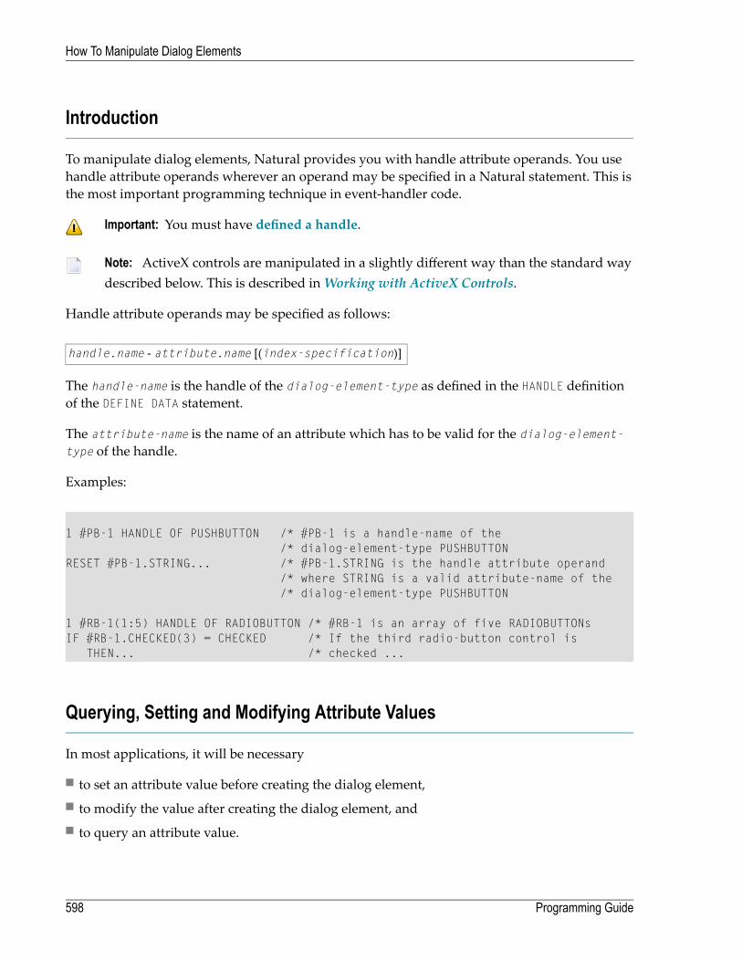
Introduction
To manipulate dialog elements, Natural provides you with handle attribute operands. You usehandle attribute operands wherever an operand may be specified in a Natural statement. This isthe most important programming technique in event-handler code.
Important: You must have defined a handle.
Note: ActiveX controls are manipulated in a slightly different way than the standard waydescribed below. This is described inWorking with ActiveX Controls.
Handle attribute operands may be specified as follows:
handle.name - attribute.name [(index-specification)]
The handle-name is the handle of the dialog-element-type as defined in the HANDLE definitionof the DEFINE DATA statement.
The attribute-name is the name of an attribute which has to be valid for the dialog-element-type of the handle.
Examples:
1 #PB-1 HANDLE OF PUSHBUTTON /* #PB-1 is a handle-name of the/* dialog-element-type PUSHBUTTON
RESET #PB-1.STRING... /* #PB-1.STRING is the handle attribute operand/* where STRING is a valid attribute-name of the/* dialog-element-type PUSHBUTTON
1 #RB-1(1:5) HANDLE OF RADIOBUTTON /* #RB-1 is an array of five RADIOBUTTONsIF #RB-1.CHECKED(3) = CHECKED /* If the third radio-button control is
THEN... /* checked ...
Querying, Setting and Modifying Attribute Values
In most applications, it will be necessary
■ to set an attribute value before creating the dialog element,■ to modify the value after creating the dialog element, and■ to query an attribute value.
Programming Guide598
How To Manipulate Dialog Elements
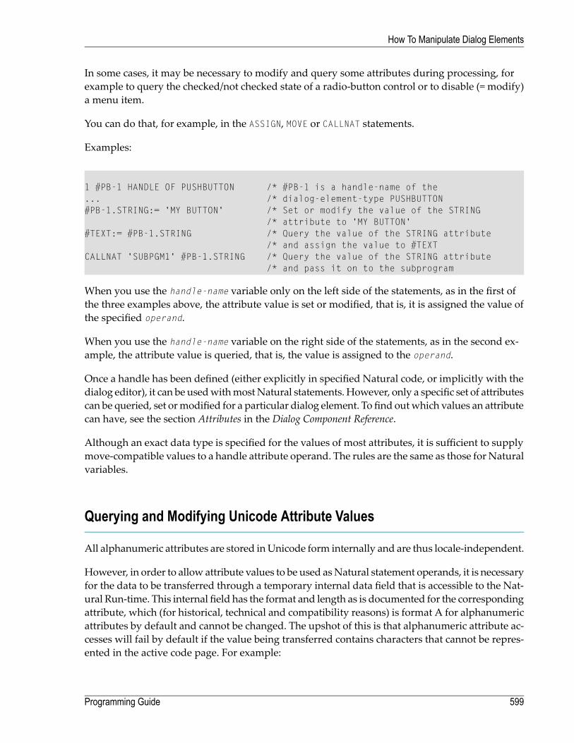
In some cases, it may be necessary to modify and query some attributes during processing, forexample to query the checked/not checked state of a radio-button control or to disable (= modify)a menu item.
You can do that, for example, in the ASSIGN, MOVE or CALLNAT statements.
Examples:
1 #PB-1 HANDLE OF PUSHBUTTON /* #PB-1 is a handle-name of the... /* dialog-element-type PUSHBUTTON#PB-1.STRING:= 'MY BUTTON' /* Set or modify the value of the STRING
/* attribute to 'MY BUTTON'#TEXT:= #PB-1.STRING /* Query the value of the STRING attribute
/* and assign the value to #TEXTCALLNAT 'SUBPGM1' #PB-1.STRING /* Query the value of the STRING attribute
/* and pass it on to the subprogram
When you use the handle-name variable only on the left side of the statements, as in the first ofthe three examples above, the attribute value is set or modified, that is, it is assigned the value ofthe specified operand.
When you use the handle-name variable on the right side of the statements, as in the second ex-ample, the attribute value is queried, that is, the value is assigned to the operand.
Once a handle has been defined (either explicitly in specified Natural code, or implicitly with thedialog editor), it can be usedwithmostNatural statements.However, only a specific set of attributescan be queried, set ormodified for a particular dialog element. To find outwhich values an attributecan have, see the section Attributes in the Dialog Component Reference.
Although an exact data type is specified for the values of most attributes, it is sufficient to supplymove-compatible values to a handle attribute operand. The rules are the same as those for Naturalvariables.
Querying and Modifying Unicode Attribute Values
All alphanumeric attributes are stored inUnicode form internally and are thus locale-independent.
However, in order to allow attribute values to be used asNatural statement operands, it is necessaryfor the data to be transferred through a temporary internal data field that is accessible to the Nat-ural Run-time. This internal field has the format and length as is documented for the correspondingattribute, which (for historical, technical and compatibility reasons) is format A for alphanumericattributes by default and cannot be changed. The upshot of this is that alphanumeric attribute ac-cesses will fail by default if the value being transferred contains characters that cannot be repres-ented in the active code page. For example:
599Programming Guide
How To Manipulate Dialog Elements

#PB-1.STRING := U'оши́бка' /* --> NAT3413 ERROR in non-Cyrillic locales
The solution to this problem is to inform Natural that the temporary internal data field should becreated with format U rather than with format A. This is done by appending a “-U” suffix to thename of any alphanumeric attribute. For example:
#PB-1.STRING-U := U'оши́бка' /* works in all locales
It is important to note that only the use of the “-U” suffix only has an effect on the format of thetemporary internal data field, not on the stored attribute. For example, there is only one STRINGattribute, regardless of whether it is addressed via the STRING or STRING-U notation. The samestorage location is used in both cases.
As a general rule, if alphanumeric attribute values are being set or retrieved that contain at least onecharacter that is not representable in the current code page, then the attribute name should be suffixed witha “-U”.
Restrictions
Handle attribute operands must not be used in the following statements:
AT BREAK, FIND, HISTOGRAM, INPUT, READ, READ WORK FILE.
User-defined variables can be used instead.
Numeric/Alphanumeric Assignment
If you assign numeric operands to alphanumeric attributes, the values of these attributes will bein a non-displayable format. The Natural arithmetic assignment rules apply.
If you need a displayable format, you can use MOVE EDITED.
Examples:
#PB-1.STRING:= -12.34 /* Non-displayable formatMOVE EDITED #I4 (EM = -Z(9)9) TO #PB-1.STRING /* Displayable format
The following edit masks may be used for the various format/length definitions of numeric oper-ands:
Programming Guide600
How To Manipulate Dialog Elements

Edit MaskFormat/Length
-ZZ9I1
-Z(5)9I2
-Z(9)9I4
-Z(n).9(m)Nn.m/Pn.m
601Programming Guide
How To Manipulate Dialog Elements

602

67 How To Create and Delete Dialog Elements Dynamically
■ Introduction .................................................................................................................................. 604■ Global Attribute List ........................................................................................................................ 604■ Creating Dialog Elements Statically and Dynamically ............................................................................ 604■ How to Handle Events of Dynamically Created Dialog Elements .............................................................. 606
603

Introduction
Dialog elements are usually added to a dialog by means of the dialog editor. However, they canalso be created and deleted dynamically. This may be done, for example, when the layout of adialog is strongly context-sensitive.
A dialog element is created dynamically with the ADD action of the PROCESS GUI statement. Thisaction returns a handle to the newly created dialog element. As soon as the dialog element is created,this handle points to a set of attributes specified for the dialog element just created.
Note: ActiveX controls are created in a slightly different way than the standard way de-scribed below. This is described inWorking with ActiveX Controls.
For more information on the actions available, and on the parameters that can be passed, see Ex-ecuting Standardized Procedures.
Global Attribute List
Bymodifying any handle attribute operand of the form handlename.attributename (for example,#PB-1.STRING), you change an attribute value of the specific dialog element. As long as the dialogelement is not yet created and the handle variable has its initial value (NULL-HANDLE), the handleattribute operand handlename.attributename refers to the global attribute list.
The global attribute list is a collection of all attributes defined for any dialog element. Naturalcontains one such collection.Whenever a dialog element is created, it “inherits” its attributes fromthis global attribute list. It does not inherit them when you create the dialog element with thePROCESS GUI statement action ADD using the WITH PARAMETERS option.
Creating Dialog Elements Statically and Dynamically
To define a dialog element statically (in the dialog editor), with an individual set of attributes, youmust first set the attributes in the global attribute list to the desired values and then create thedialog element. After creation, the values of the attributes in the global attribute list remain intact.The next created dialog element gets the same attributes from the global attribute list as the previousone, except those that have been modified.
The status of the global attribute list as found in the “after open” event handler is influenced bythe dialog elements defined statically. Therefore, before you start creating dialog elements dynam-ically in the “after open” event handler, you should reset the attributes by means of the PROCESSGUI action RESET-ATTRIBUTES to prevent your dialog elements from inheriting unexpected values
Programming Guide604
How To Create and Delete Dialog Elements Dynamically
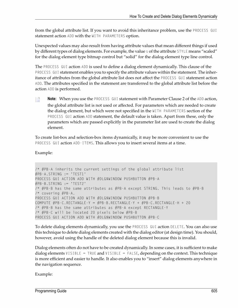
from the global attribute list. If you want to avoid this inheritance problem, use the PROCESS GUIstatement action ADDwith the WITH PARAMETERS option.
Unexpected values may also result from having attribute values that mean different things if usedby different types of dialog elements. For example, the value s of the attribute STYLEmeans “scaled”for the dialog element type bitmap control but “solid” for the dialog element type line control.
The PROCESS GUI action ADD is used to define a dialog element dynamically. This clause of thePROCESS GUI statement enables you to specify the attribute valueswithin the statement. The inher-itance of attributes from the global attribute list does not affect the PROCESS GUI statement actionADD. The attributes specified in the statement are transferred to the global attribute list before theaction ADD is performed.
Note: When you use the PROCESS GUI statement with Parameter Clause 2 of the ADD action,the global attribute list is not used or affected. For parameters which are needed to createthe dialog element, but which were not specified in the WITH PARAMETERS section of thePROCESS GUI action ADD statement, the default value is taken. Apart from these, only theparameters which are passed explicitly in the parameter list are used to create the dialogelement.
To create list-box and selection-box items dynamically, it may be more convenient to use thePROCESS GUI action ADD-ITEMS. This allows you to insert several items at a time.
Example:
/* #PB-A inherits the current settings of the global attribute list#PB-A.STRING := 'TEST1'PROCESS GUI ACTION ADD WITH #DLG$WINDOW PUSHBUTTON #PB-A#PB-B.STRING := 'TEST2'/* #PB-B has the same attributes as #PB-A except STRING. This leads to #PB-B/* covering #PB-A.PROCESS GUI ACTION ADD WITH #DLG$WINDOW PUSHBUTTON #PB-BCOMPUTE #PB-C.RECTANGLE-Y = #PB-B.RECTANGLE-Y + #PB-C.RECTANGLE-H + 20/* #PB-B has the same attributes as #PB-A except RECTANGLE-Y/* #PB-C will be located 20 pixels below #PB-BPROCESS GUI ACTION ADD WITH #DLG$WINDOW PUSHBUTTON #PB-C
To delete dialog elements dynamically, you use the PROCESS GUI action DELETE. You can also usethis technique to delete dialog elements createdwith the dialog editor (at design time). You should,however, avoid using the handle of the deleted dialog element because this is invalid.
Dialog elements often do not have to be created dynamically. In some cases, it is sufficient tomakedialog elements VISIBLE = TRUE and VISIBLE = FALSE, depending on the context. This techniqueis more efficient and easier to handle. It also enables you to “insert” dialog elements anywhere inthe navigation sequence.
Example:
605Programming Guide
How To Create and Delete Dialog Elements Dynamically
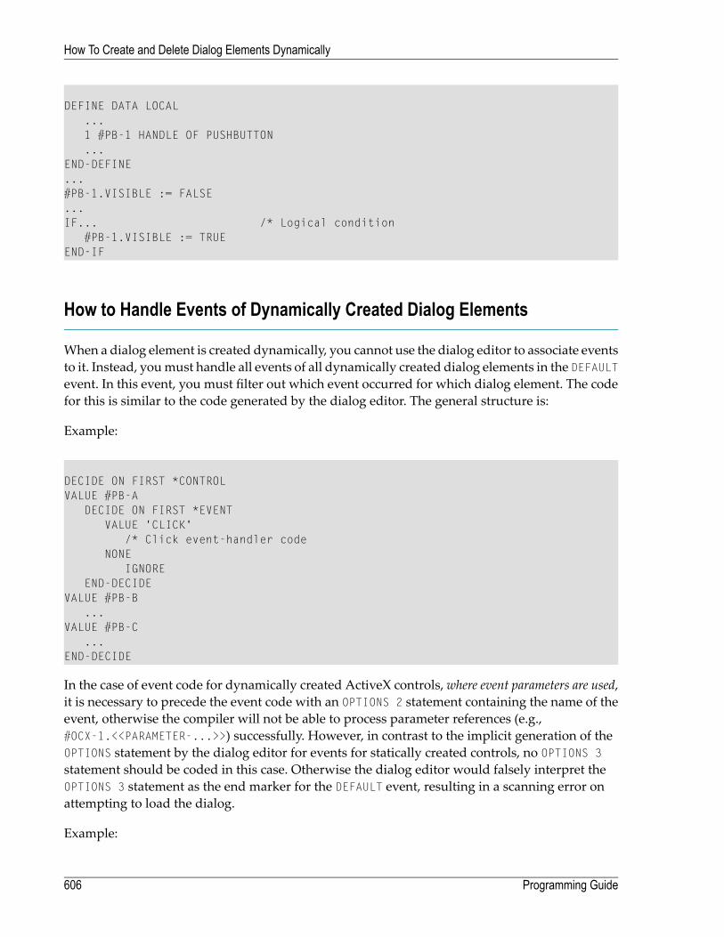
DEFINE DATA LOCAL...1 #PB-1 HANDLE OF PUSHBUTTON...
END-DEFINE...#PB-1.VISIBLE := FALSE...IF... /* Logical condition
#PB-1.VISIBLE := TRUEEND-IF
How to Handle Events of Dynamically Created Dialog Elements
When a dialog element is created dynamically, you cannot use the dialog editor to associate eventsto it. Instead, youmust handle all events of all dynamically created dialog elements in the DEFAULTevent. In this event, you must filter out which event occurred for which dialog element. The codefor this is similar to the code generated by the dialog editor. The general structure is:
Example:
DECIDE ON FIRST *CONTROLVALUE #PB-A
DECIDE ON FIRST *EVENTVALUE 'CLICK'
/* Click event-handler codeNONE
IGNOREEND-DECIDE
VALUE #PB-B...
VALUE #PB-C...
END-DECIDE
In the case of event code for dynamically created ActiveX controls, where event parameters are used,it is necessary to precede the event code with an OPTIONS 2 statement containing the name of theevent, otherwise the compiler will not be able to process parameter references (e.g.,#OCX-1.<<PARAMETER-...>>) successfully. However, in contrast to the implicit generation of theOPTIONS statement by the dialog editor for events for statically created controls, no OPTIONS 3statement should be coded in this case. Otherwise the dialog editor would falsely interpret theOPTIONS 3 statement as the end marker for the DEFAULT event, resulting in a scanning error onattempting to load the dialog.
Example:
Programming Guide606
How To Create and Delete Dialog Elements Dynamically

DECIDE ON FIRST *CONTROLVALUE #OCX-1 /* MS Calendar control
DECIDE ON FIRST *EVENTVALUE '-602' /* DispID for KeyDown event
OPTIONS 2 KeyDown/* KeyDown event-handler code containing parameter/* access (e.g. #OCX-1.<<parameter-shift>>)
NONEIGNORE
END-DECIDE...END-DECIDE
607Programming Guide
How To Create and Delete Dialog Elements Dynamically

608

68 How To Enable and Disable Dialog Elements
During end-user interaction, it may be implicitly clear that certain dialog elements must not beused. For example, if a dialog requiring personnel data contains a group of radio button controlsfor marital status and an input field control for date of marriage, the input field control must bedisabled whenever the marital status is other than married.
There are two ways to do this:
■ Use Natural code to enable/disable a dialog element dynamically.■ Use the dialog editor (to disable a dialog element initially).
The first method is used more often.
The Natural code might look like this:
/*First alternative...IF #RB-1.ENABLED = TRUE /* Logical condition
#IF-1.ENABLED := TRUE /* Set ENABLED to TRUEEND-IF.../*Second alternative#PB-1.ENABLED := #RB-1.ENABLED
When you use the dialog editor, you set the attribute ENABLED to TRUE by marking the Enabledentry in the dialog element's attributes window.
To disable editing in input-field controls, selection box controls and edit area controls, it is not al-ways necessary to disable these dialog elements entirely. It may be sufficient to make them MODI-FIABLE = FALSE.
609

610

69 Defining and Using Context Menus
■ Introduction .................................................................................................................................. 612■ Construction ................................................................................................................................. 612■ Association ................................................................................................................................... 613■ Invocation .................................................................................................................................... 614■ Manual Invocation ......................................................................................................................... 617■ Sharing of Context Menus ............................................................................................................... 618
611

Introduction
As from Natural v4.1.1, it is possible to create context menus for use within Natural applications.The context menus can be completely static (i.e., the menu contents are known in advance andcan be built via the dialog editor) or wholly or partially dynamic (i.e., the menu contents and/orstate depend on the runtime context and are not completely known at design time).
Construction
A context menu is very similar in concept to a submenu. Therefore, the same menu editor is usedfor editing a context menu as is used for editing a dialog's menu bar. Menu items can be addedto context menus, and events associated with them, in exactly the same way as for menu-barsubmenus. There are no functional differences to the menu bar editor, except that theOLE combobox (which is applicable only to top-level menu-bar submenus) will always be disabled. It shouldbe noted, however, that any accelerators defined for context menu items will be globally availableas long as thatmenu item exists. Furthermore, the acceleratorwill trigger themenu item forwhichit is defined even if the context menu is not being displayed or if the focus is on a control using adifferent context menu or no context menu at all.
The context menu editor may be invoked via either a new menu item, Context menus... on theDialogmenu, or via its associated accelerator (CTRL+ALT+X by default), or toolbar icon. However,because the contextmenu editor can only edit one contextmenu editor at a time, the context-menueditor is not invoked directly. Instead, theDialog Context Menuswindow is shown, where oper-ations on the context menu as a whole are made, and from which the menu editor for a given(selected) context menu can be invoked.
Internally, in order to distinguish between submenus and context menus, context menus have anew type, CONTEXT MENU. Otherwise, the generated code in both cases is identical. Here is somesample code illustrating the statements used to build up a simple context menu containing twomenu items:
/* CREATE CONTEXT MENU ITSELF:PROCESS GUI ACTION ADD WITH PARAMETERS
HANDLE-VARIABLE = #CONTEXT-MENU-1TYPE = CONTEXTMENUPARENT = #DLG$WINDOW
END-PARAMETERS GIVING *ERROR/* ADD FIRST MENU ITEM:PROCESS GUI ACTION ADD WITH PARAMETERS
HANDLE-VARIABLE = #MITEM-1TYPE = MENUITEMDIL-TEXT = 'Invokes the first item'
Programming Guide612
Defining and Using Context Menus

PARENT = #CONTEXT-MENU-1STRING = 'Item 1'
END-PARAMETERS GIVING *ERROR/* ADD SECOND MENU ITEM:PROCESS GUI ACTION ADD WITH PARAMETERS
HANDLE-VARIABLE = #MITEM-2TYPE = MENUITEMDIL-TEXT = 'Invokes the second item'PARENT = #CONTEXT-MENU-1STRING = 'Item 2'
END-PARAMETERS GIVING *ERROR
Note that if context menus or context-menu items are created dynamically in user-written code,the context menu or menu items will not be visible to the dialog editor. For example, the dynam-ically created menu item will not be visible in the context menu list box, and the dynamicallycreated menu items will not be visible in the context menu editor.
Association
After creating a context menu, the context menu needs to be associated with a Natural object.Contextmenus are supported for almost all controls types capable of receiving the keyboard focusand for the dialog window itself. The full list includes ActiveX controls, bitmaps, canvasses, editareas and input fields, list boxes, push buttons, radio buttons, scroll bars, selection boxes, tablecontrols, toggle buttons, standard and MDI child windows, and MDI frame windows.
For all object types supporting context menus, the corresponding attribute dialogs in the dialogeditor include a read-only combo box listing all contextmenus created by the dialog editor, togetherwith an empty entry. The selection of the empty entry implies that no context menu is to be usedfor this object, and is the default.
Internally, the association is achieved by a new attribute, CONTEXT MENU, which should be set tothe handle of a context menu. This attribute can be assigned at or after object creation time, anddefaults to NULL-HANDLE if not specified, indicating the absence of a context menu. For contextmenus created by the dialog editor, the context menu is specified at control creation time as illus-trated below:
PROCESS GUI ACTION ADD WITHPARAMETERS
HANDLE-VARIABLE = #LB-1TYPE = LISTBOXRECTANGLE-X = 585RECTANGLE-Y = 293RECTANGLE-W = 142RECTANGLE-H = 209MULTI-SELECTION = TRUE
613Programming Guide
Defining and Using Context Menus

SORTED = FALSEPARENT = #DLG$WINDOWCONTEXT-MENU = #CONTEXT-MENU-1SUPPRESS-FILL-EVENT = SUPPRESSED
END-PARAMETERS GIVING *ERROR
The same syntax can also be used for controls created in user-written event code. In other cases,where the controlwas created by the dialog editor but the contextmenuwas not, the contextmenuattribute must be assigned to the control after its creation, e.g., in the dialog's AFTER-OPEN event:
/* CONTEXT MENU SPECIFIED AFTER CREATION:
#LB-2.CONTEXT-MENU := #CONTEXT-MENU-2
Note that a context menu is not destroyed when an object using it is destroyed. Instead, it is des-troyed when its parent object (typically, the dialog for which the context menu was defined) isdestroyed. Similarly, the assignment of a new menu handle to the CONTEXT MENU attribute whereone is already assigned does not result in the previous context menu being destroyed. Thus, usingthe above examples, neither of the following statements results in CONTEXT-MENU-1 being destroyed:
PROCESS GUI ACTION DELETE WITH #LB-1 /* #CONTEXT-MENU-1 LIVES ON
#LB-1.CONTEXT-MENU := #CONTEXT-MENU-2 /* SAME HERE
Invocation
The context menu invocation process in Natural is as follows:
1. If the context menu is accessed via the mouse (i.e., secondary mouse button click), the targetcontrol is initially assumed to be the control immediately under the mouse cursor. Otherwise,if the context menu is accessed via the keyboard (i.e., either via the context menu key, if any,or via the key combination Shift+F10), the target control is initially assumed to be the control thatcurrently has the keyboard focus.
2. The control's click position is set, relative to the target control's client area. If the context menuis accessed via the keyboard, the click position is set to (0, 0).
3. A CONTEXT-MENU event is raised for the target control, if not suppressed via the SUPPRESS-CON-TEXT-MENU-EVENT attribute.
4. The target control's CONTEXT-MENU attribute is queried. Depending on its value and the type ofthe target control, the following action is taken:■ If the attribute is set to NULL-HANDLE and the target control is a dialog, the context menu in-vocation process is aborted, without any context menu having been displayed.
Programming Guide614
Defining and Using Context Menus
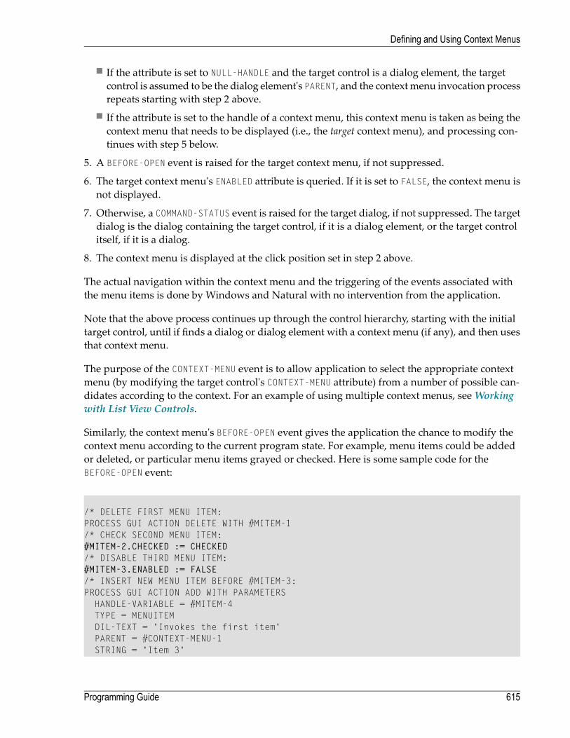
■ If the attribute is set to NULL-HANDLE and the target control is a dialog element, the targetcontrol is assumed to be the dialog element's PARENT, and the contextmenu invocation processrepeats starting with step 2 above.
■ If the attribute is set to the handle of a context menu, this context menu is taken as being thecontext menu that needs to be displayed (i.e., the target context menu), and processing con-tinues with step 5 below.
5. A BEFORE-OPEN event is raised for the target context menu, if not suppressed.
6. The target context menu's ENABLED attribute is queried. If it is set to FALSE, the context menu isnot displayed.
7. Otherwise, a COMMAND-STATUS event is raised for the target dialog, if not suppressed. The targetdialog is the dialog containing the target control, if it is a dialog element, or the target controlitself, if it is a dialog.
8. The context menu is displayed at the click position set in step 2 above.
The actual navigation within the context menu and the triggering of the events associated withthe menu items is done by Windows and Natural with no intervention from the application.
Note that the above process continues up through the control hierarchy, starting with the initialtarget control, until if finds a dialog or dialog element with a context menu (if any), and then usesthat context menu.
The purpose of the CONTEXT-MENU event is to allow application to select the appropriate contextmenu (by modifying the target control's CONTEXT-MENU attribute) from a number of possible can-didates according to the context. For an example of using multiple context menus, seeWorkingwith List View Controls.
Similarly, the context menu's BEFORE-OPEN event gives the application the chance to modify thecontext menu according to the current program state. For example, menu items could be addedor deleted, or particular menu items grayed or checked. Here is some sample code for theBEFORE-OPEN event:
/* DELETE FIRST MENU ITEM:PROCESS GUI ACTION DELETE WITH #MITEM-1/* CHECK SECOND MENU ITEM:#MITEM-2.CHECKED := CHECKED/* DISABLE THIRD MENU ITEM:#MITEM-3.ENABLED := FALSE/* INSERT NEW MENU ITEM BEFORE #MITEM-3:PROCESS GUI ACTION ADD WITH PARAMETERS
HANDLE-VARIABLE = #MITEM-4TYPE = MENUITEMDIL-TEXT = 'Invokes the first item'PARENT = #CONTEXT-MENU-1STRING = 'Item 3'
615Programming Guide
Defining and Using Context Menus

SUCCESSOR = #MITEM-3END-PARAMETERS GIVING *ERROR
For context menus not created by the dialog editor, the handling of the BEFORE-OPEN event mustbe done in the DEFAULT event for the dialog. Note also that if a control or dialog is disabled, nocontext menu is displayed, and the BEFORE-OPEN event is also not triggered. The same applies ifthe context menu itself is disabled. For example:
#CONTEXT-MENU-1.ENABLED := FALSE /* DISABLE CONTEXT MENU DISPLAY
Note that it is possible to disable the context menu in this way during the BEFORE-OPEN event, al-lowing selective disabling of the context menu depending on the mouse cursor position withinthe control. For example, it might be desired to only display a context menu if the mouse cursoris over a selected list-box item. Determining whether this is the case is possible via the use of twoPROCESS GUI ACTION calls:
■ INQ-CLICKPOSITION has been extended to controls other than bitmaps and canvasses to returnthe (X, Y) position of the rightmouse button clickwithin the control. In addition, these parametersare now optional, and a new optional parameter has been introduced that is set to TRUE if thecontext menu was accessed via the mouse, or FALSE if it was accessed by the keyboard. In thelatter case, the click position is set to (0, 0). All this information is updated immediately priorto the sending of the BEFORE-OPEN event.
■ INQ-ITEM-BY-POSITION. This allows translation of the relative co-ordinate returned byINQ-CLICKPOSITION applied to a list box to the corresponding item.
As an example of the use of these two new actions, consider the situation where we want to detectwhether the cursor was over a selected list-box item when the right mouse button was pressed inorder to determinewhether to display a contextmenu or not. This can be achieved by the followingcode in the BEFORE-OPEN event of the associated context menu:
PROCESS GUI ACTION INQ-CLICKPOSITION WITH#LB-1 #X-OFFSET #Y-OFFSET
PROCESS GUI ACTION INQ-ITEM-BY-POSITION WITH#LB-1 #X-OFFSET #Y-OFFSET #LBITEM
#MENU = *CONTROLIF #LBITEM = NULL-HANDLE /* NO ITEM UNDER (MOUSE) CURSOR */
#MENU.ENABLED := FALSEELSE
IF #LBITEM.SELECTED = FALSE /* ITEM UNDER CURSOR DESELECTED */#MENU.ENABLED := FALSE
ELSE /* ITEM UNDER CURSOR IS SELECTED */#MENU.ENABLED := TRUE
END-IFEND-IF
Programming Guide616
Defining and Using Context Menus

In some cases, it may be desired to automatically select the item under the mouse cursor if it isnot already selected, clearing any existing selection. For list boxes, it is possible to achieve this byusing the new AUTOSELECT attribute, either directly or via the new Autoselect check box in theList Box Attributeswindow in the dialog editor. If this attribute is set to TRUE, Natural will auto-matically update the selection before sending the BEFORE-OPEN event, if the context menu was in-voked over an unselected list-box item.
For table controls, any change in the selection must be done via the application itself in theBEFORE-OPEN event. Tomake this possible, another new PROCESS GUI ACTION has been introducedfor table controls:
■ TABLE-INQUIRE-CELL. This returns the cell's row and column number (starting from 1) for a rel-ative (X, Y) position within the table. This position can (and would typically be) the positionreturned by a previous call to PROCESS GUI ACTION INQ-CLICKPOSITION.
The COMMAND-STATUS event is an alternative location for the application to perform any updatingsuch as graying and checking of commands (i.e., menu items, tool bar items and signals). If youare already using this event, you do not need to perform these actions in the BEFORE-OPEN event.
Manual Invocation
In addition to the automatic context menu invocation process described above, it is also possibleto invoke a particular context menu manually at a specific position via the SHOW-CONTEXT-MENUaction.
This is primarily intended for (but not restricted to) usewithActiveX controls where the automaticmechanism is not always applicable. This is because some ActiveX controls, depending on theirinternal implementation, do not raise the message used by Natural to trigger the context menudisplay. In such cases, if the ActiveX control raises an event when the secondary mouse button ispressed, the context menu can be manually displayed within the event handler for that event viathis action.
For example, assuming we wish to display the context menu #CTXMENU-1 for the Microsoft RichTextbox ActiveX Control, #OCX-1, we could use the following code in the control's MouseDownevent handler:
IF #OCX-1.<<PARAMETER-Button>> = 2#X := #OCX-1.<<PARAMETER-x>> + 2#Y := #OCX-1.<<PARAMETER-y>> + 2PROCESS GUI ACTION SHOW-CONTEXT-MENU WITH
#CTXMENU-1 #OCX-1 #X #Y GIVING *ERROREND-IF
where the following local data definitions are assumed:
617Programming Guide
Defining and Using Context Menus

01 #X (I4)01 #Y (I4)
Note that the above code first checks whether the secondary mouse button was pressed, then in-vokes a context menu manually, based on the position passed by the control. The position is,however, first corrected slightly to account for the fact that the position supplied by the control isrelative to the ActiveX control (which has a 2-pixel sunken border), whereas the position used todisplay the context menu is assumed to be relative to the ActiveX control's containerwindow(which has no border).
Note that some ActiveX controls may return coordinates in units other than pixels, such as twips(twentieths of a point). The following example shows how to convert co-ordinates (#X, #Y) fromtwips to pixels:
#CONTROL := *CONTROL/* Convert x-coordinateMULTIPLY #X BY #CONTROL.DPIDIVIDE #X BY 1440/* Convert y-coordinateMULTIPLY #Y BY #CONTROL.DPIDIVIDE #Y BY 1440
where #CONTROL is defined as HANDLE OF GUI, and #X and #Y are assumed to be of format I4.
The value 1440 is the number of twips per logical inch, whereas the DPI attribute applied to adialog element returns the number of pixels per logical inch.
Sharing of Context Menus
It is of course possible to associate the same context menu with more than one object (i.e., controlor dialog). For example:
#LB-1.CONTEXT-MENU := #CTXMENU-1#LB-2.CONTEXT-MENU := #CTXMENU-1
In such a scenario,we need to be able to determine forwhich control the contextmenuwas invoked.We cannot use *CONTROL in the BEFORE-OPEN event, because this will contain the handle of thecontext menu itself. Instead, it is necessary to inquire which control has the focus, since Naturalautomatically places the focus on the control for which the context menu is being invoked. Hereis some sample BEFORE-OPEN event code illustrating the use of this technique:
Programming Guide618
Defining and Using Context Menus
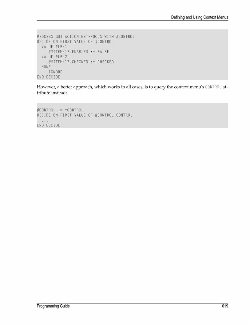
PROCESS GUI ACTION GET-FOCUS WITH #CONTROLDECIDE ON FIRST VALUE OF #CONTROL
VALUE #LB-1#MITEM-17.ENABLED := FALSE
VALUE #LB-2#MITEM-17.CHECKED := CHECKED
NONEIGNORE
END-DECIDE
However, a better approach, which works in all cases, is to query the context menu's CONTROL at-tribute instead:
#CONTROL := *CONTROLDECIDE ON FIRST VALUE OF #CONTROL.CONTROL
...END-DECIDE
619Programming Guide
Defining and Using Context Menus

620

70 Using the Clipboard and Drag and Drop
■ Introduction .................................................................................................................................. 622■ Clipboard Specifics ........................................................................................................................ 624■ Drag and Drop Specifics ................................................................................................................. 625■ Drag and Drop Insertion Marks ......................................................................................................... 627■ Drag-Drop Checklist ....................................................................................................................... 628
621

Introduction
Both clipboard and drag/drop data transfermake use of a logical clipboard at theNatural languagelevel, allowing a single set of methods to handle both requirements. The PROCESS GUI actions forhandling the logical clipboard are as follows: OPEN-CLIPBOARD, SET-CLIPBOARD-DATA,CLOSE-CLIPBOARD, GET-CLIPBOARD-DATA and INQ-FORMAT-AVAILABLE. Each Natural process hasexactly one logical clipboard, which is why it is referred to in the product documentation as the“local” clipboard.
OPEN-CLIPBOARD is the first step in building up the logical clipboard data. It takes an optionalparameter (owner window), which is typically the handle of the control sourcing the data. Ifanything was previously on the logical clipboard, this action empties it. Note that you don't needto call this for drag and drop, because Natural does this implicitly before raising the BEGIN-DRAGevent (see below).
SET-CLIPBOARD-DATA puts the actual data on the logical clipboard. The first parameter is the clip-board format, specified as a string. There are two pre-defined formats (defined in NGULKEY1 asCF-TEXT and CF-FILELIST), which are used for standard text transfer, and lists of files (suitablefor data exchange with theWindows Explorer andmany other applications) respectively. In addi-tion, an arbitrary string (which should not begin with a dgit) should be used to indicate a privateclipboard format that onlyNatural applications can understand (they just need to know the formatstring so they can pass it to GET-CLIPBOARD-DATA to retrieve the data). The second and subsequentarguments are an arbitrary number of data operands. These can be any combination of arrays(incl. index ranges) or scalars (incl. dynamic and large alpha variables). Arrays are internally ex-panded into their individual elements, which are then handled individually as for scalars.
For example, the following code:
DEFINE DATA LOCAL1 #ARR(A1/2,3) INIT (1,1)<'A'> (1,2)<'B'> (1,3)<'C'>
(2,1)<'X'> (2,2)<'Y'> (2,3)<'Z'>END-DEFINEPROCESS GUI ACTION SET-CLIPBOARD-DATA WITH CF-TEXT #ARR(*,*)
is equivalent to:
PROCESS GUI ACTION SET-CLIPBOARD-DATA WITH CF-TEXT'A' 'B' 'C' 'X' 'Y' 'Z'
For the pre-defined formats, the operands must be alphanumeric (format A). For private formats,the data arguments can be of almost any type. Exception: handle variables (incl. HANDLE OF OBJECT)are not supported, because they are process-specific. The data for private formats is stored “as-is”(i.e., no conversion).
Programming Guide622
Using the Clipboard and Drag and Drop

Note that multiple data formats can be placed on the clipboard by performing aSET-CLIPBOARD-DATA action for each required format. However, any call to SET-CLIPBOARD-DATAfor a particular format replaces any data that may already exist in that format.
Note also that the data is not placed on the Windows clipboard. This is done when the logicalclipboard is closed (see below).
CLOSE-CLIPBOARD closes the logical clipboard, and places the data on the Windows clipboard, sothat it becomes available for pasting into other applications. The data cannot be modified bySET-CLIPBOARD-DATA after this call. Note that this call is not necessary for drag and drop becauseyou usually don't need to also make the dragged data available for pasting. Drag and drop canwork directly with the logical clipboard.
GET-CLIPBOARD-DATA is used by the application performing the paste or acting as the drop targetto retrieves the data from the drag-drop clipboard (if a drag and drop operation is in progress) orfrom the Windows clipboard otherwise. The drag-drop clipboard is a synonym for the logicalclipboard belonging to the source Natural process. SET-CLIPBOARD-DATA, a clipboard format isspecified, followed by an arbitrary list of data operands (with the same format type restrictions).For private formats, the operands need not have the same format type as used in theGET-CLIPBOARD-DATA action. For example, you can place an integer on the clipboard and read itback into a packed numeric (P) variable. Internally, a MOVE conversion is done. Therefore, if differentformat types are used for setting and getting the data, they must be MOVE-compatible.
For pre-defined formats, where the individual data items are either delimited by CR/LF (for CF-TEXT format) or by null-terminators (for CF-FILELIST format), only one item is usually read intoeach receiving field. Exception: If the last receiving field is a dynamic alpha variable, it receivesall remaining data items, including the delimiters. This exception allows the application to use(for example) a single dynamic alpha variable to set and get multiple lines of data or multiplefile/directory names. Regardless of the format used, if too many receiving operands are specified,the excess fields are reset (see the RESET statement). Note that individual data fieldsmay be skippedby using the nX notation. For example, 5x skips 5 data items (where a “data item” is a single linefor CF-TEXT format).
INQ-FORMAT-AVAILABLE is used for querying whether data is available in a given format (see spe-cification for syntax). It is typically used to determine whether to enable or disable the Pastecommand, or whether to display the “no drop” cursor for drag/drop operations.
623Programming Guide
Using the Clipboard and Drag and Drop
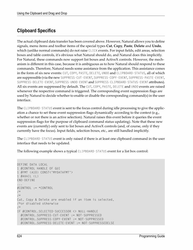
Clipboard Specifics
The actual clipboard data transfer has been covered above. However, Natural allows you to definesignals, menu items and toolbar items of the special types Cut, Copy, Paste, Delete and Undo,which (unlike normal commands) do not raise CLICK events. For input fields, edit areas, selectionboxes and table controls, it's obvious what Natural should do, and Natural does this implicitly.For Natural, these commands now support list boxes and ActiveX controls. However, the mech-anism is different in this case, because it is ambiguous as to how Natural should respond to thesecommands. Therefore, Natural needs some assistance from the application. This assistance comesin the form of six new events: CUT, COPY, PASTE, DELETE, UNDO and CLIPBOARD-STATUS, all of whichare suppressible (via the new SUPPRESS-CUT-EVENT, SUPPRESS-COPY-EVENT, SUPPRESS-PASTE-EVENT,SUPPRESS-DELETE-EVENT,SUPPRESS-UNDO-EVENT andSUPPRESS-CLIPBOARD-STATUS-EVENT attributes).All six events are suppressed by default. The CUT, COPY, PASTE, DELETE and UNDO events are raisedwhenever the respective command is triggered. The corresponding event suppression flags areused byNatural to decide whether to enable or disable the corresponding command(s) in the userinterface.
The CLIPBOARD-STATUS event is sent to the focus control during idle processing to give the applic-ation a chance to set these event suppression flags dynamically according to the context (e.g.,whether or not there is an active selection). Natural raises this event before it queries the eventsuppression flags for the purpose of clipboard command status updating). Note that these newevents are (currently) only sent to list boxes and ActiveX controls (and, of course, only if theycurrently have the focus). Input fields, selection boxes, etc., are still handled implicitly.
The CLIPBOARD-STATUS event is only raised if there is at least one clipboard command in the userinterface that needs to be updated.
The following example shows a typical CLIPBOARD-STATUS event for a list box control:
DEFINE DATA LOCAL1 #CONTROL HANDLE OF GUI1 #FMT (A10) CONST<'MYDATAFMT'>1 #AVAIL (L)END-DEFINE...#CONTROL := *CONTROL/*/*Cut, Copy & Delete are enabled if an item is selected,/*or disabled otherwise/*IF #CONTROL.SELECTED-SUCCESSOR <> NULL-HANDLE
#CONTROL.SUPPRESS-CUT-EVENT := NOT-SUPPRESSED#CONTROL.SUPPRESS-COPY-EVENT := NOT-SUPPRESSED#CONTROL.SUPPRESS-DELETE-EVENT := NOT-SUPPRESSEDELSE
Programming Guide624
Using the Clipboard and Drag and Drop

#CONTROL.SUPPRESS-CUT-EVENT := SUPPRESSED#CONTROL.SUPPRESS-COPY-EVENT := SUPPRESSED#CONTROL.SUPPRESS-DELETE-EVENT := SUPPRESSED
END-IF/*/* Paste command is enabled if data is available in a/* recognized format, or disabled otherwise/*PROCESS GUI ACTION INQ-FORMAT-AVAILABLEWITH #FMT #AVAIL GIVING *ERROR/*IF #BOOL
#CONTROL.SUPPRESS-PASTE-EVENT := NOT-SUPPRESSEDELSE
#CONTROL.SUPPRESS-PASTE-EVENT := SUPPRESSEDEND-IF
Drag and Drop Specifics
Drag and drop operations can be triggered automatically (for list boxes and bitmap controls) ormanually, via the new PERFORM-DRAG-DROP action (typically for ActiveX controls in response tocontrol-specificmouse click or drag start events). For automatic drag/drop, themouse cursormustbe over the active selection (if any). Formanual drag/drop, the parameters for PERFORM-DRAG-DROPinclude the handle of the control that should receive the drag/drop events (the drag source), andan optional flag indicating whether drag and drop should begin immediately, or only after theuser moves the mouse a system-defined minimum number of pixels. Both automatic and manualdrag/drop use the same code internally, so the same events are received in both cases.
Drag/drop is controlled by by two new I4 attributes, DRAG-MODE (for drag sources) and DROP-MODE(for drop targets). These attributes can be set to one of 8 values (defined in NGULKEY1): DM-NONE(no drag/drop allowed), DM-COPY (copy allowed), DM-MOVE (move allowed), DM-COPYMOVE (copyand move allowed), DM-LINK (link allowed), DM-COPYLINK (copy and link allowed), DM-MOVELINK(move and link allowed), DM-COPYMOVELINK (copy, move and link allowed). Link operations implythat the drop target should create a link to the source data, rather than creating a copy of it. Forfile operations, desktop shortcuts are typically used (not currently explicitly supported byNatural).Drag operations are only initiated if the source's DRAG-MODE attribute is set to something other thatthe default DM-NONE value. In addition, the application must respond to the BEGIN-DRAG event (seebelow).
Control types capable of acting as drop targets are: ActiveX controls, bitmap controls, list boxes,control boxes, edit areas, and dialogs (tab controls and table controls are planned for the futurebut are not currently supported). These windows are, however, only registered with OLE as droptargets if their DROP-MODE attribute is set to something other that the default DM-NONE value. Duringa drag/drop operation, OLE automatically searches up through the window hierarchy, startingwith the window immediately under the cursor, until it finds a window that has been registered
625Programming Guide
Using the Clipboard and Drag and Drop

as a drop target. This is the window that gets the OLE drop notifications and therefore is thewindow that receives the Natural drag/drop events (see below).
The new drag/drop related events are: BEGIN-DRAG, END-DRAG, DRAG-ENTER, DRAG-OVER andDRAG-LEAVE. In addition, the existing DRAG-DROP event (for theMickeyMouse non-OLE drag/dropsupport for bitmap controls) is also used. All events are suppressible via the appropriate eventsuppression attributes (SUPPRESS-BEGIN-DRAG-EVENT etc.), all of which are SUPPRESSED by default.
The BEGIN-DRAG event (if not suppressed) is sent to the drag source on initiation of a drag operation.The application must use the SET-CLIPBOARD-DATA action to place some data on the drag/dropclipboard before returning from this event, otherwise the drag/drop operation is implicitly cancelledwithout the mouse cursor having changed. Note that there is no need to call either of theOPEN-CLIPBOARD or CLOSE-CLIPBOARD actions.
The END-DRAG event (if not suppressed) is sent to the drag source after a drag/drop operation hascompleted (even if the drag operation was cancelled). The main use of this event is to delete thesource data if a Move operation occurred. The application can find out whether a Move operationhas occurred by calling the existing INQ-DRAG-DROP action, which has been extended with twonew optional integer output parameters. The first of these new parameters indicates whichmousebuttons are currently pressed (1 = Left button, 2 = Right button, 4 =Middle button, or a combinationthereof). The second newparameter is the onewe need here, and contains the drop effect resultingfrom a drag/drop operation (DM-NONE if no drop or if the operation was cancelled, DM-COPY if aCopy operation was performed, DM-MOVE if a Move operation was performed, and DM-LINK if alink operation was performed.
The DRAG-ENTER event (if not suppressed) is sent to the drop target when the drag cursor (re-)entersthe region occupied by the drop target. The application typically responds to this event by callingthe INQ-FORMAT-AVAILABLE action to find out if a compatible data format is available on the clip-board, and then setting the SUPPRESS-DRAG-DROP-EVENT attribute accordingly. The SUPPRESS-DRAG-DROP-EVENT is important because it not only determines whether the DRAG-DROP event should beraised, but also informs Natural as to whether a drop should be allowed. After raising theDRAG-ENTER and DRAG-OVER events, Natural inspects the SUPPRESS-DRAG-DROP-EVENT attribute anddisplays a “no drop” symbol. Otherwise, the drop effect is determined by the combination of thedrag source's DRAG-MODE value, the drop target's DROP-MODE value, and the augmentation keys(SHIFT and CTRL) that are currently being pressed.
The DRAG-OVER event (if not suppressed) is frequently sent to the drop target as the drag cursormoves over the drop target. It can be used, for example, to update the drop emphasis (if any) asthe user traverses the items within the control and/or to update the SUPPRESS-DRAG-DROP-EVENTattribute if the feasibility of a drop operation depends on the position within the drop target.
The DRAG-LEAVE event (if not suppressed) is sent to the drop target when the drag cursor leavesthe region occupied by the drop target without a drop having occurred. This is mainly used (if atall) to remove the drop emphasis (if any) applied in the DRAG-OVER event.
Programming Guide626
Using the Clipboard and Drag and Drop

The DRAG-DROP event (if not suppressed) is sent to the drop target when the user performs a drop.drag cursor leaves the region occupied by the drop target without a drop having occurred. Theapplication should respond to this by effectively performing a Paste operation, using the currentrelative positionwithin the control, if necessary. Both the relative position and the type of operationcan be retrieved via the INQ-DRAG-DROP action. The latter is returned in the new (optional) “dropeffect” parameter (see the description of the END-DRAG event above for more information).
Drag and Drop Insertion Marks
For list boxes, a new "insertion mark (i)" style can be used to indicate that a dashed horizontal linebe used to indicate the current insert position when the drag cursor is moved over the control(assuming it is a drop target). The application cannot query the insertion mark position directly,but can find out where to insert the data by querying the relative position within the control viathe INQ-DRAG-DROP action, then passing these coordinates to the INQ-ITEM-BY-POSITION action,as in the following example:
DEFINE DATA LOCAL1 #Y (I4)1 #CONTROL HANDLE OF GUI1 #ITEM HANDLE OF GUIEND-DEFINE.../* DRAG-DROP event:PROCESS GUI ACTION INQ-DRAG-DROP WITH 4X #Y GIVING *ERROR*IF #Y < 0
#Y := 0END-IF#CONTROL := *CONTROLPROCESS GUI ACTION INQ-ITEM-BY-POSITION WITH#CONTROL 0 #Y #ITEM GIVING *ERROR
After the above code has executed, the variable #ITEM contains the handle of the item immediatelyfollowing the insertion point. You can then dynamically insert one or more list box items at thisposition by calling the ADD actionwith the WITH PARAMETERS clause, setting the SUCCESSOR attributeto #ITEM.
Note that the correction for negative y-coordinate in the above example is necessary to cover thesituation where the drop position is on the list boxes top border. If no correction would be madehere, #ITEMwould be set to NULL-HANDLE and the new list box item(s) would be added undesirablyat the end of the list instead of at the beginning if we were to directly use #ITEM as the SUCCESSORattribute, as described above.
627Programming Guide
Using the Clipboard and Drag and Drop

Drag-Drop Checklist
For convenience, here is a brief overview of the steps involved in implementing drag-drop inNatural applications:
1. Set the DRAG-MODE for each drag source. If the drag source is a bitmap control, its DRAGGABLEattribute must also be set to TRUE.
2. Set SET-CLIPBOARD-DATA in the BEGIN-DRAG event for each drag source to provide the transferdata.
3. Set the DROP-MODE for each drop target.
4. In the DRAG-ENTER event, use the INQ-FORMAT-AVAILABLE action to set the SUPPRESS-DRAG-DROP-EVENT attribute to NOT-SUPPRESSED (0) if a supported clipboard format is available, orSUPPRESSED (1) otherwise. If the control can also act as a drag source and you need to prohibitdrag-drop operations within the control, call INQ-DRAG-DROP to get the source control handleand compare it to the current control (*CONTROL), suppressing the drag-drop event if both areidentical.
5. If the effect of the drop is position-sensitive within the target control, use the INQ-DRAG-DROPaction within the DRAG-OVER event to get the current position, determine the item under thedrag cursor (e.g. via the INQ-ITEM-BY-POSITION action) and set the SUPPRESS-DRAG-DROP-EVENTattribute appropriately. Highlight the current item if desired.
6. If the current itemwas highlighted in step 5 above, unhighlight it (if necessary) in the DRAG-LEAVEand (potentially) DRAG-DROP events.
7. Use GET-CLIPBOARD-DATA in the DRAG-DROP event to retrieve the transfer data and process itaccordingly.
8. In the END-DRAG event for the drag source, delete the source data if the drop effect returned byINQ-DRAG-DROP is set to DM-MOVE.
9. If the drag source is an ActiveX control, call the PERFORM-DRAG-DROP action to initiate the drag-drop operation in response to a "MouseDown" event (for example) if a locationwithin the currentselection is clicked.
Example - Use of X-Arrays for Transferring Data
One of the problems in setting or retrieving data that may need to be placed or already have beenplaced on the Windows or drag-drop clipboard in response to a user interaction is being able tocope with an arbitrary amount of data at run-time. For example, the user may select a single, afew, or possibly even hundreds or thousands of list box items before performing a clipboard ordrag-drop operation on them. With fixed-size arrays, one would have to define huge arrays tocope with the worst-case scenario, even though typically only a small percentage would be usedmost of the time.
Programming Guide628
Using the Clipboard and Drag and Drop

There are two possible solutions to this problem available in Natural. The first way is to use asingle dynamic alpha variable to contain all items to be set or retrieved. The application is thenresponsible for building up the items (including delimiters) in the dynamic variable before callingSET-CLIPBOARD-DATA, and for extracting the items from the dynamic variable after callingGET-CLIPBOARD-DATA. This approach is not possible for private formats, because these are not de-limited.
The second approach is tomake use of X-Arrays. For setting clipboard data, these behave similarlyto fixed-size arrays, except that their size can bemodified to contain exactly the number of elementsneeded in a specific situation. For example, if there are 17 items that need to be written to theclipboard, then you can use:
DEFINE DATA LOCAL1 #X-ARR(A80/1:*)1 #UPB (I4) INIT <17>END-DEFINERESIZE ARRAY #X-ARR TO (1:#UPB)PROCESS GUI ACTION SET-CLIPBOARD-DATA WITH CF-TEXT #X-ARR(*)
instead of having to use a wastefully large fixed array, of which only a small range is used:
DEFINE DATA LOCAL1 #ARR(A80/10000)1 #UPB (I4) INIT <17>END-DEFINEPROCESS GUI ACTION SET-CLIPBOARD-DATA WITH CF-TEXT ARR(1:#UPB)
When retrieving clipboard data, X-Arrays are even more useful, because the application does notknow in advance how many items are on the clipboard. Passing all array elements (10,000 in theabove example) would be relatively slow, because all unused elements need to be reset.
However, if an X-Array is used instead, Natural automatically resizes the array to (1:N), where Nis the minimum of the number of items (remaining) on the clipboard and the array's maximumupper bound (as defined in DEFINE-DATA, where * indicates the maximum possible value). Notethat there are three restrictions on the use of X-Arrays in conjunction with GET-CLIPBOARD-DATA:
■ The X-Array must be the last (or only) parameter.■ Only 1-dimensional X-Arrays are supported.■ The X-Arrays defined range must include the element 1.
Here is an example program illustrating the use of a dynamic X-Array for retrieving clipboarddata, including the use of a second X-Array to store and display the data lengths:
629Programming Guide
Using the Clipboard and Drag and Drop
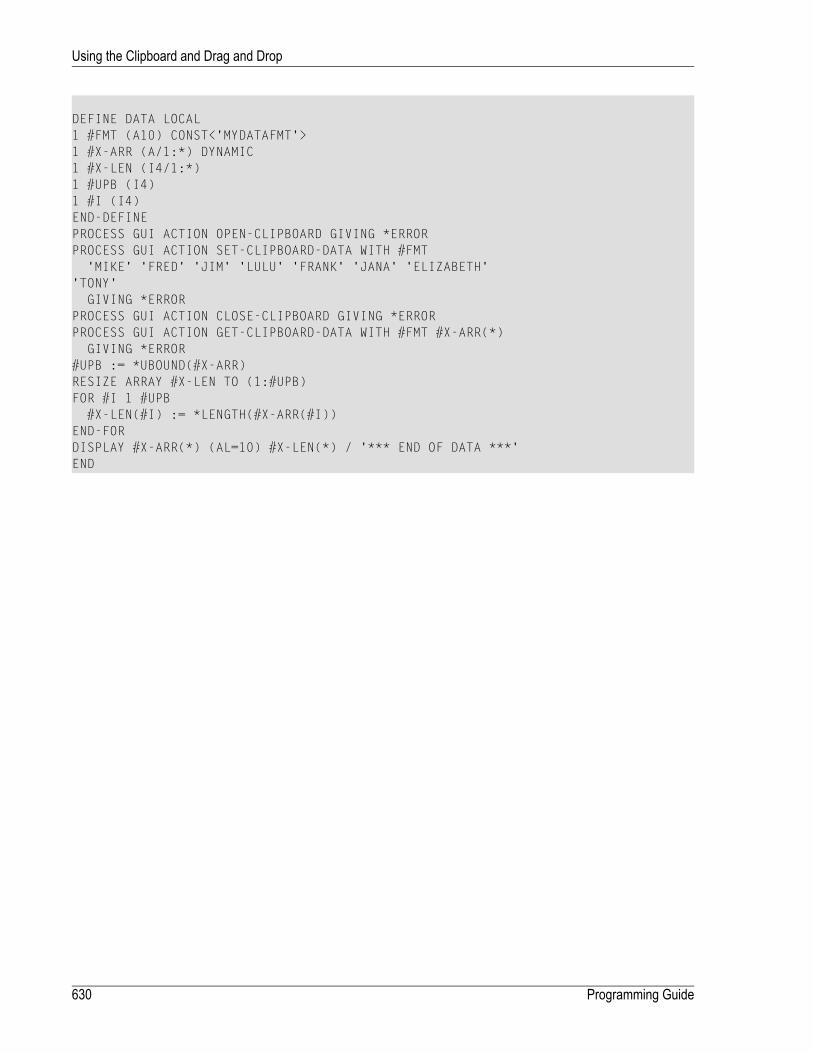
DEFINE DATA LOCAL1 #FMT (A10) CONST<'MYDATAFMT'>1 #X-ARR (A/1:*) DYNAMIC1 #X-LEN (I4/1:*)1 #UPB (I4)1 #I (I4)END-DEFINEPROCESS GUI ACTION OPEN-CLIPBOARD GIVING *ERRORPROCESS GUI ACTION SET-CLIPBOARD-DATA WITH #FMT
'MIKE' 'FRED' 'JIM' 'LULU' 'FRANK' 'JANA' 'ELIZABETH''TONY'
GIVING *ERRORPROCESS GUI ACTION CLOSE-CLIPBOARD GIVING *ERRORPROCESS GUI ACTION GET-CLIPBOARD-DATA WITH #FMT #X-ARR(*)
GIVING *ERROR#UPB := *UBOUND(#X-ARR)RESIZE ARRAY #X-LEN TO (1:#UPB)FOR #I 1 #UPB
#X-LEN(#I) := *LENGTH(#X-ARR(#I))END-FORDISPLAY #X-ARR(*) (AL=10) #X-LEN(*) / '*** END OF DATA ***'END
Programming Guide630
Using the Clipboard and Drag and Drop

71 System Variables
Whenever you specify an event to occur with a given dialog element, the dialog editor generatescode containing the Natural system variables *CONTROL, *DIALOG-ID and *EVENT.
During the processing, *CONTROL contains the dialog element's handle, *EVENT contains the eventname and *DIALOG-ID identifies an instance of a dialog.
You can reference these system variables whenever you enter Natural code within the dialog ed-itor. If, for example, the end user clicks on a push button control and the event handler calls ashared subroutine, you can use these system variables as logical condition criteria to trigger thesubroutine.
For further details on these system variables, see the System Variables documentation.
631

632

72 Generated Variables
■ #DLG$PARENT ............................................................................................................................ 634■ #DLG$WINDOW ........................................................................................................................... 634
633

#DLG$PARENT
You use this generated variable of type "user" to work with MDI child windows, for example.When you create a dialog, Natural generates this variable in order to hold the handle of the parentdialog. In event-handler code, you can, for example, use this variable to open anMDI child dialogfrom another MDI child dialog, as shown below.
Note: You should not use names for user-defined variables that begin with #DLG$ to avoidconflicts with generated variables.
Example:
OPEN DIALOG 'MDICHILD' #DLG$PARENT #CHILD-ID
#DLG$WINDOW
You use this generated variable to dynamically set the attributes within a dialog.When you createa dialog, Natural generates this variable in order to hold the handle of the dialog window.#DLG$WINDOW is the default name of this variable; you may change it by overwriting theNameentry in the upper left of the dialog's attributes window. In event-handler code, you can, for ex-ample, use this variable to minimize the dialog window if certain logical condition criteria aremet, as shown below.
#DLG$WINDOW represents the graphical user interface aspects of a dialog, while the *DIALOG-IDsystem variable represents the runtime aspects. *DIALOG-IDmust be used in OPEN DIALOG, CLOSEDIALOG and SEND EVENT statements.
Note: You should not use names for user-defined variables that begin with #DLG$ to avoidconflicts with generated variables.
Example:
...IF ...
#DLG$WINDOW.MINIMIZED := TRUEEND-IF...
Programming Guide634
Generated Variables
73 Using the TERMINATE or STOP Statements within
Dialog-based Applications■ Introduction .................................................................................................................................. 636■ Solution ....................................................................................................................................... 636■ Example ...................................................................................................................................... 636
635

Introduction
The execution of the TERMINATE and STOP statements relies on stack-based exception handlingin order to immediately abort the application’s execution, which is not guaranteed to work withinevent-driven (i.e., dialog-based) applications in consumer versions ofWindows. In particular, thiscan be the casewhere one ormore events on theNatural call stack have been synchronously raisedin response to the corresponding system event(s). This is because the relevant section of the systemcall stack in such situations can containWindows system code that has been compiledwith a smallperformance optimization to not generate the required stack frame information at run-time.
Furthermore, because the Windows system code involved changes over time, a TERMINATE orSTOP statement that works on one version of Windows is not guaranteed to continue to work onall later versions, or even on all later Service Packs for the same version.
For these reasons, the use of the TERMINATE and STOP statements in dialog-based applicationsis discouraged.
Solution
A universal solution is not available. However, in many cases, the problem can be circumventedby performing the termination asynchronously. For example, instead of coding a TERMINATEor STOP statement directly, one instead asynchronously invokes a user-defined event for thedialog via the CALL-DIALOG action, and places the TERMINATE or STOP statement within theevent handler for the user-defined event, as illustrated in the example below.
In particular, this workaround is applicable in situations where no dialog boxes are active.
Example
Suppose that the CLOSE event for a modeless dialog contains a TERMINATE statement.
/* CLOSE eventTERMINATE
This TERMINATE statement fails in some Windows versions in the case where the user attemptsto close the dialog via the Close (X) icon.
To solve this problem, we can firstly define a user-defined event for the dialog (e.g., with the name“TERMINATE”), and insert the TERMINATE statement there:
Programming Guide636
Using the TERMINATE or STOP Statements within Dialog-based Applications

/* TERMINATE eventTERMINATE
Secondly, we replace the original TERMINATE statement in the CLOSE event with the followingtwo statements:
/* CLOSE eventPROCESS GUI ACTION CALL-DIALOG WITH
#DLG$WINDOW NULL-HANDLE 'TERMINATE' FALSE GIVING *ERRORESCAPE ROUTINE IMMEDIATE
TheCALL-DIALOGactionwith the FALSE parameter causes the TERMINATE event to be executedasynchronously. The ESCAPE statement by-passes any subsequent event code and is absolutelynecessary in this case to ensure that the DELETE-WINDOWaction generated by the Dialog Editoris not performed, so that the dialog remains active until the TERMINATE event is received.
637Programming Guide
Using the TERMINATE or STOP Statements within Dialog-based Applications

638

74 Message Files and Variables as Sources of Attribute
Values
Most dialog elements have a STRING attribute. As an alternative to specifying the attribute valueby typing in the text in the String entry of the attributes window, you can select a variable or amessage file number from which the text is taken at runtime. In this case, the attribute value isdetermined by the variable's current value or the selected message file at the dialog element'screation time. You can also specify attribute sources for the BITMAP-FILE-NAME, DIL-TEXT and AC-CELERATOR attributes.
To select a message file number or specify a variable
1 Invoke the dialog element's attribute window.
2 Choose the Source button to the right of the String entry.
TheAttribute Source dialog box appears. The default attribute source is "Constant"; you canalso enter the number of the message file, or enter the variable name.
Note: If you are using an integer variable as the source of an attribute value, note that atruntime, the message with the corresponding number from your message file will be dis-played. To avoid this, you can MOVE the contents of this integer variable to a variable offormat N, for example.
639

640

75 Triggering User-Defined Events
■ Introduction .................................................................................................................................. 642■ Passing Parameters to the Dialog ..................................................................................................... 643
641

Introduction
Aside from standard events, such as before-open, youmay define user-defined events for dialogs.User-defined events are useful whenever it is necessary for one dialog to cause an action to occurin another dialog.
A user-defined event occurs whenever you have specified a SEND EVENT statement in dialog Awith the name of a user-defined event in the target dialog B. This target dialog B for which youwish to trigger the user-defined event must already be active. You can activate dialog B by usingthe OPEN DIALOG statement. If you do not issue the OPEN DIALOG statement first, the SEND EVENTstatement will cause a runtime error.
You can define your own events for dialogs by choosing theNew button in the Events dialogevent handler menu or from the dialog's context menu. Enter any name for your newly-definedevent and specify the corresponding event section. It is recommended that this name begin witha hash (#) to distinguish your event from predefined events.
During execution of an event handler, the SEND EVENT statement triggers the user-defined eventhandler in a different dialog. After this user-defined event handler has been executed, control willbe returned to the previous dialog, whose execution will resume at the statement following theSEND EVENT statement. This can be compared to a CALLNAT statement that causes a subprogram tobe executed.
Similar to the OPEN DIALOG statement, parameters may be passed to the dialog. In order to passparameters selectively (PARAMETERS-clause), you have to specify the name of the dialog in additionto the identifier of the dialog (operand2).
The SEND EVENT statement must not trigger an event in a dialog that is about to process an event.This is the case, for example, when dialog A sends an event to dialog B and the event handler indialog B sends an event to dialog A which has not yet finished its event handling. A similar caseis when dialog A opens dialog B and the before-open or after-open event contains a SEND EVENTback to dialog A.
To trigger a user-defined event, you specify the following syntax:
SEND EVENT operand1 TO [DIALOG-ID] operand2
WITH operand3... USING [DIALOG] 'dialog-name'WITH PARAMETRS-clause
Operands
Operand1 is the name of the event to be sent.
Programming Guide642
Triggering User-Defined Events

Operand2 is the identifier of the dialog receiving the user-defined event and must be defined withformat/length I4. You can retrieve this identifier, for example, by querying the value of#DLG$PARENT.CLIENT-DATA.
Passing Parameters to the Dialog
It is possible to pass parameters to the dialog receiving the user event.
As operand3 you specify the parameters which are passed to the dialog.
With the PARAMETERS-clause, parameters may be passed selectively.
PARAMETERS-clause
PARAMETERS [parameter-name = operand3]_ END-PARAMETERS
Note: You may only use the PARAMETERS-clause if the target dialog is cataloged.
Dialog-name is the name of the dialog receiving the user-defined event.
When you use only operand3 to pass parameters, it might look like this:
/* The following parameters are defined in the dialog's/* parameter data area:1 #DLG-PARM1 (A10)1 #DLG-PARM2 (A10)1 #DLG-PARM3 (A10)1 #DLG-PARM4 (A10)/* When sending the user-defined event, pass the operands #MYPARM1 'MYPARM2' tothe parameters #DLG-PARM1 and #DLG-PARM2:SEND EVENT 'MYEVENT' TO #DLG$DIA-ID WITH #MYPARM1 'MYPARM2'
When you use the PARAMETERS-clause, the user-defined event might look like this:
/* The following parameters are defined in the dialog's/* parameter data area:1 #DLG-PARM1 (A10)1 #DLG-PARM2 (A10)1 #DLG-PARM3 (A10)1 #DLG-PARM4 (A10)/* When sending the user-defined event, the operand #MYPARM2 is passed to the/* parameter #DLG-PARM2 and the operand 'MYPARM3' is passed to the parameter/* #DLG-PARM3:SEND EVENT 'MYEVENT' TO #DLG$DIA-ID
643Programming Guide
Triggering User-Defined Events

USING DIALOG 'MYDIALOG'WITH PARAMETERS
#DLG-PARM3='MYPARM3'#DLG-PARM2=#MYPARM2
END-PARAMETERS
To avoid format/length conflicts between operands passed and their parameter definitions, seethe BY VALUE option of the DEFINE DATA statement in the Statements documentation.
Programming Guide644
Triggering User-Defined Events
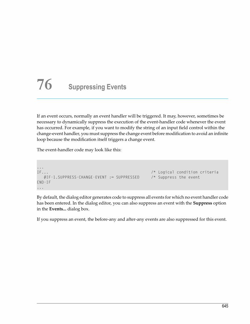
76 Suppressing Events
If an event occurs, normally an event handler will be triggered. It may, however, sometimes benecessary to dynamically suppress the execution of the event-handler code whenever the eventhas occurred. For example, if you want to modify the string of an input field control within thechange-event handler, youmust suppress the change event beforemodification to avoid an infiniteloop because the modification itself triggers a change event.
The event-handler code may look like this:
...IF... /* Logical condition criteria
#IF-1.SUPPRESS-CHANGE-EVENT := SUPPRESSED /* Suppress the eventEND-IF...
By default, the dialog editor generates code to suppress all events for which no event handler codehas been entered. In the dialog editor, you can also suppress an event with the Suppress optionin the Events... dialog box.
If you suppress an event, the before-any and after-any events are also suppressed for this event.
645

646

77 Menu Structures, Toolbars and the MDI
■ Creating a Menu Structure ............................................................................................................... 648■ Parent-Child Hierarchy in Menu Structures ......................................................................................... 650■ Creating a Toolbar ......................................................................................................................... 650■ Sharing Menu Structures, Toolbars and DILs (MDI Application) ............................................................... 651
647

Creating a Menu Structure
A menu structure consists of three types of dialog elements:
■ menu-bar controls,■ menu items,■ submenu controls.
A menu structure has one menu-bar control consisting of several menu items. The menu bar withits items is displayed directly beneath the window's title bar. Each menu item may be simple ormay represent a submenu control, which allows you to pull down several menu items groupedvertically. Therefore, submenu controls may contain items representing a submenu control onelevel lower. A submenu control becomes visible when the representing item in the menu-barcontrol or the parent submenu control is clicked upon.
There are two ways to create menu structures:
■ Use the dialog editor; or■ use Natural code.
If you use the dialog editor
1. Check theMenu Bar entry in the dialog's attribute window. ChooseOK. When you go back tothe dialog, a dummy menu-bar control appears.
2. Double-click on the dummymenu-bar control, or from theNaturalMenu, selectDialog >MenuBar, or use CTRL+M. TheDialog Menu Bar dialog box appears. This dialog box is divided intothree group frames: menu bar, selected submenu and selected menu item.
3. In the selected menu items group frame, useNew to add a menu item behind the selected pos-ition, or at the beginning. Now use the selected menu-item group frame to modify attributevalues or add event handlers to the new menu item.
Normal menu items have a click event whose code is executed when the end user clicks on themenu item.
Note: The MENU-ITEM-TYPE of themenu item can also be "Separator", in which case the itemis no text item.
If you use Natural code
1. Create a Menu Bar with the PARENT attribute set to NULL-HANDLE or windowhandle.
2. To create a simple menu item: the PARENT attribute must have the value menubarhandlename.
Programming Guide648
Menu Structures, Toolbars and the MDI

3. To create a submenu control: the submenu control's PARENT attribute must have the valueNULL-HANDLE or windowhandlename. Then create amenu itemwith PARENT = menubarhandlenameand MENU-HANDLE = submenuhandlename.
4. Then associate the menu bar with a dialog window by updating the window's MENU-HANDLEattribute with the handle of the menu bar as set in the first step.
5. The event handling for the dynamically created menu items must be done in the default eventhandler, as described in the section How to Create and Delete Dialog Elements Dynamically.
The PARENT attribute determines when the menu bar or the submenu control will be destroyed.When PARENT = windowhandlename, the menu bar/the submenu control will be destroyed whenthe window is destroyed. This is the default setting, which is also used by the dialog editor. IfPARENT = NULL-HANDLE, themenu bar/the submenu control will be destroyed onlywhen the applic-ation is terminated.
If you define themenu structure's handles inside a global data area, you can share these definitionsamong several dialogs.
To build the above menu structure
1 Define the handles of the menu-bar control, the menu items, and the submenu control(s) asthe user-defined variables in the handler of the applicable event.
2 Create the controls and items by assigning values to the attributes (PARENT, ...) and by executingthe PROCESS GUI statement action ADD.
3 Create the controls and items in the sequence menu-bar control, submenu control with menuitems.
4 Insert the controls and items in the sequence submenu control into menu-bar control, andmenu-bar control into dialog window.
You can study how to build a menu structure in code by using the enhanced dialog list mode tolist a dialog with an editor-built menu. To get a code model for creating a menu item, create amenu bar control with the dialog editor, go to themenu-bar control attributeswindow, cut amenuitem and paste it into any chosen event-handler section. The generated code for the menu itemappears.
649Programming Guide
Menu Structures, Toolbars and the MDI

Parent-Child Hierarchy in Menu Structures
Sometimes, it is necessary to use code for going through each element in a menu structure. Formenus, the parent-child hierarchy is structured in a way that is not evident from the graphicalrepresentation of the menu structure.
In the above diagram, the first child of the dialog would be the menu-bar control. Its successorwould be submenu control S1, and so on. To go from menu item MI-1 to submenu S1, you queryfor the MENU-HANDLE attribute value of MI-1. The value you get is the handle value of S1.
Creating a Toolbar
There are two ways of creating toolbars and their items:
■ Use the dialog editor; or■ use Natural code to create them dynamically.
To use the dialog editor
1 Double-click on the toolbar or from the Natural Menu, selectDialog > Toolbar. The toolbarattributes window opens.
Programming Guide650
Menu Structures, Toolbars and the MDI

2 Add toolbar items by choosing theNew button.
3 Assign bitmap file names and other attribute values to the new toolbar item.
If you want to use Natural code for dynamic creation, you can study how to build a tool bar incode. Use the enhanced dialog list mode to list a dialog with an editor-built tool bar.
Sharing Menu Structures, Toolbars and DILs (MDI Application)
An MDI (multiple document interface) application consists of a frame dialog that provides themenu structure, toolbar, and DIL shared among all child dialogs. An MDI frame dialog allowsyou to tile or cascade its child dialogs.
Note: Youmay only share the toolbar if the PARENT of the toolbar is the dialog of the highestlevel (the main dialog of an application).
To create an MDI frame dialog
1 Use the dialog editor, and go to the dialog object's attributes window.
2 Choose "MDI frame window" in the Type entry.
An MDI frame dialog must not contain dialog elements other than menu-bar control, submenucontrol, menu item, toolbar, and toolbar item.
To create an MDI child dialog
1 Use the dialog editor, and go to the dialog object's attributes window.
2 Choose "MDI child window" in the Type entry.
An MDI child dialog:
■ can be moved and sized only inside the area of their MDI frame dialog;■ can be maximized to the full size of the area of their MDI frame dialog;■ can be minimized, after which its icon appears at the bottom of its MDI frame dialog;■ can have its own menu structure, toolbar, and DIL. Those do not appear inside the child dialogbut are displayed in the MDI frame dialog when the child dialog is active. When another MDIchild dialog becomes active, the menu structure, toolbar, and DIL change at the same time;
■ can be arranged in a tile or cascade by setting a menu item's attribute MENU-ITEM-TYPE to thevalues "MDI Cascade" or "MDI Tile";
■ can have its title added to the end of an MDI-WINDOWMENU type submenu control. Bychoosing one of these menu items, the corresponding MDI child dialog becomes active.
651Programming Guide
Menu Structures, Toolbars and the MDI

If you want to open an MDI child dialog from within an MDI frame dialog, you can, for example,create a menu item in a menu structure of an MDI frame dialog and define a click event for themenu item. You then write the OPEN DIALOG code for opening an MDI child dialog in the clickevent handler. The end user will open the MDI child dialog from within the MDI frame dialog byclicking on the menu item, triggering the click event handler.
Example:
OPEN DIALOG 'MDICHILD' #DLG$WINDOW #CHILD-ID
The first operand is the name of the dialog created by the dialog editor by selecting "MDI childwindow" in theType selection box. The second operand is the parent of the newMDI child dialog.This must be the MDI frame dialog. The third operand is a Natural variable defined as I4 in thedialog's data areas. This variable receives the dialog ID returned by the system.
Note: #DLG$WINDOW is a generated variable.
You can also open an MDI child dialog from within another MDI child dialog (open a sibling ofyour MDI child dialog). Then you write a similar click-event handler as above:
OPEN DIALOG 'MDICHILD' #DLG$PARENT #CHILD-ID
The first and the third operands are the same as above. The second operand must be the parentof both MDI child dialogs.
Note: #DLG$PARENT is a generated variable.
Programming Guide652
Menu Structures, Toolbars and the MDI

78 Executing Standardized Procedures
■ Introduction .................................................................................................................................. 654■ PROCESS GUI Statement .............................................................................................................. 654
653

Introduction
For procedures frequently needed in event-driven applications, the following is available:
■ a set of PROCESS GUI statement actions and■ a set of NGU-prefixed subprograms and dialogs in library SYSTEM.
Examples for frequently needed procedures are starting up amessage box, reading the lines enteredinto an edit area control, or dynamically creating dialog elements.
For your convenience, the local data areasNGULKEY1 andNGULFCT1 are automatically includedin the list of local data areas used by any new dialog.
■ NGULFCT1 is necessary to use the NGU-prefixed subprograms and dialogs;■ NGULKEY1 lists reserved keywords to be used in any event-handler code. This enables you torefer to certain attribute values by the more meaningful keyword rather than by the numericIDs. It also enables you to use meaningful dialog element names as parameters.
For more information on the PROCESS GUI statement actions, subprograms and dialogs available,and on the parameters that can be passed, refer to the Dialog Component Reference.
PROCESS GUI Statement
The PROCESS GUI statement is used to perform an action. An action in this context is a procedurefrequently needed in event-driven applications.
As action-name, you specify the name of the action to be invoked.
As operand1, you specify the parameter(s) to be passed to the action. The parameters are passedin the sequence in which they are specified.
For the action ADD, you can also pass parameters by name (instead of position); to do so, you usethe PARAMETERS-clause:
PARAMETERS [parameter-name = operand1]_ END-PARAMETERS
This clause can only be used for the action ADD, not for any other action.
As operand2, you can specify a field to receive the response code from the invoked action afterthe action has been performed.
Programming Guide654
Executing Standardized Procedures
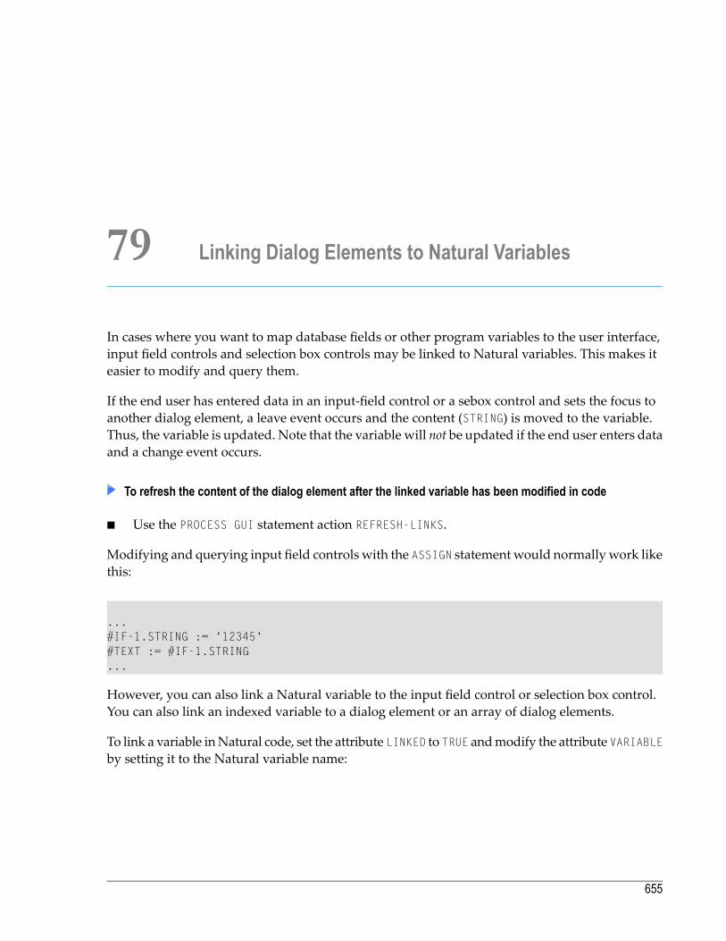
79 Linking Dialog Elements to Natural Variables
In cases where you want to map database fields or other program variables to the user interface,input field controls and selection box controls may be linked to Natural variables. This makes iteasier to modify and query them.
If the end user has entered data in an input-field control or a sebox control and sets the focus toanother dialog element, a leave event occurs and the content (STRING) is moved to the variable.Thus, the variable is updated. Note that the variable will not be updated if the end user enters dataand a change event occurs.
To refresh the content of the dialog element after the linked variable has been modified in code
■ Use the PROCESS GUI statement action REFRESH-LINKS.
Modifying and querying input field controls with the ASSIGN statementwould normallywork likethis:
...#IF-1.STRING := '12345'#TEXT := #IF-1.STRING...
However, you can also link a Natural variable to the input field control or selection box control.You can also link an indexed variable to a dialog element or an array of dialog elements.
To link a variable inNatural code, set the attribute LINKED to TRUE andmodify the attribute VARIABLEby setting it to the Natural variable name:
655

...#IF-1.LINKED := TRUE#IF-1.VARIABLE := MYVARIABLE...
To use the dialog editor to enter the name of the Natural variable
1. Double-click on your input field control. The corresponding attributes window appears.
2. Choose the Source button to the right of the String entry. The Source for handlename dialogbox appears.
3. Choose Linked variable.
4. Enter the variable name (such as MYVARIABLE in the example above).
There are two possibilities to link an indexed variable such as MYVARIABLE (A20/1:5):
■ you link a single dialog element to the indexed variable; then you specify the index, such asMYVARIABLE(2) in the variable name field of the Source for handlename dialog box, or
■ you link an array of dialog elements to the indexed variable; then you do not specify an indexin the variable name field. In this case, the occurrences of the array and the index of the variablemust be compatible. MYVARIABLE (A20/1:5) could be linked to a one-dimensional array withup to five occurrences.
Programming Guide656
Linking Dialog Elements to Natural Variables
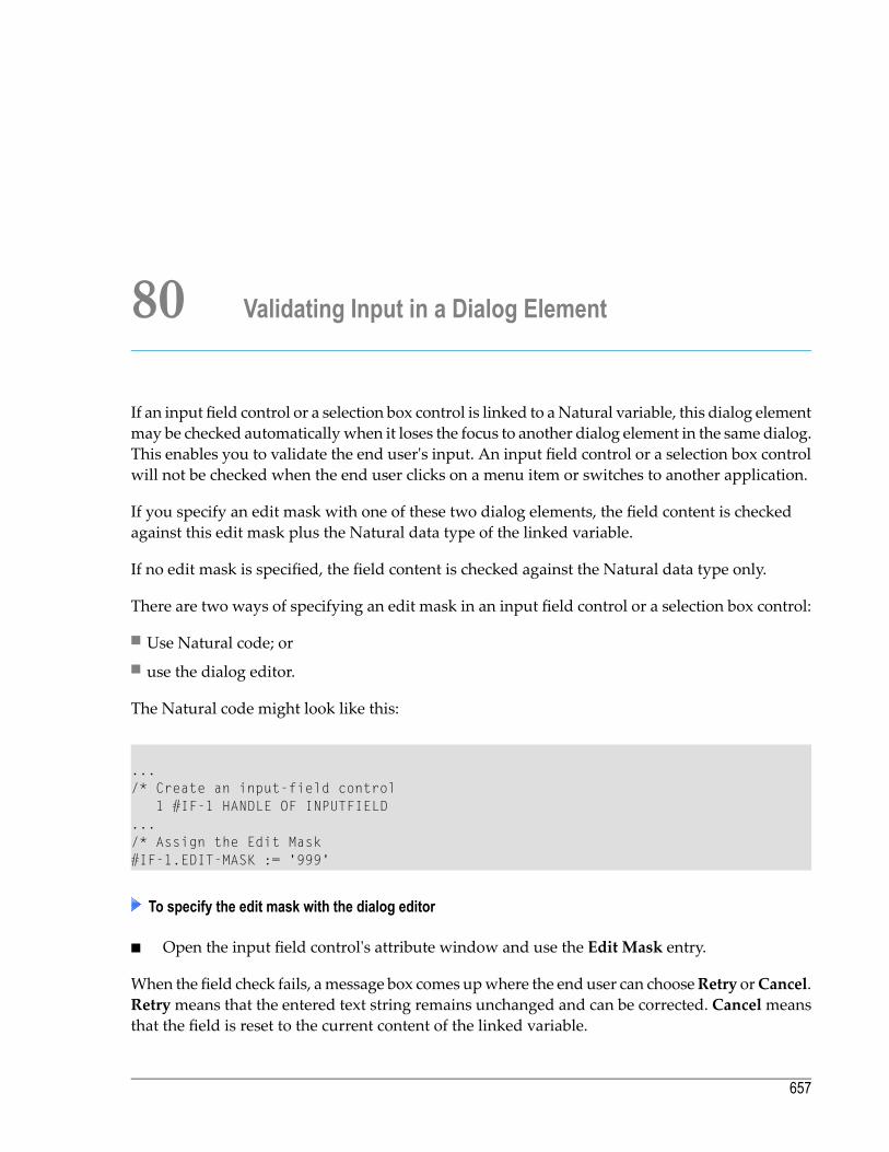
80 Validating Input in a Dialog Element
If an input field control or a selection box control is linked to aNatural variable, this dialog elementmay be checked automaticallywhen it loses the focus to another dialog element in the same dialog.This enables you to validate the end user's input. An input field control or a selection box controlwill not be checked when the end user clicks on a menu item or switches to another application.
If you specify an edit mask with one of these two dialog elements, the field content is checkedagainst this edit mask plus the Natural data type of the linked variable.
If no edit mask is specified, the field content is checked against the Natural data type only.
There are two ways of specifying an edit mask in an input field control or a selection box control:
■ Use Natural code; or■ use the dialog editor.
The Natural code might look like this:
.../* Create an input-field control
1 #IF-1 HANDLE OF INPUTFIELD.../* Assign the Edit Mask#IF-1.EDIT-MASK := '999'
To specify the edit mask with the dialog editor
■ Open the input field control's attribute window and use the Edit Mask entry.
When the field check fails, amessage box comes upwhere the end user can chooseRetry orCancel.Retrymeans that the entered text string remains unchanged and can be corrected. Cancelmeansthat the field is reset to the current content of the linked variable.
657

658

81 Storing and Retrieving Client Data for a Dialog Element
■ Introduction .................................................................................................................................. 660■ Integer Data ................................................................................................................................. 660■ Handle Data ................................................................................................................................. 661■ Keyed Alphanumeric Client Data ...................................................................................................... 661■ Keyed Client Data in Native Format ................................................................................................... 664■ Key Enumeration ........................................................................................................................... 667
659

Introduction
This section refers to the association of arbitrary user-defined information (“client data”) with a(dialog or) dialog element. There are various complementary ways of achieving this, which willbe discussed in detail in the following sections. The attributes and actions relating to the manipu-lation of client data in Natural are (in the order they are discussed in this document):
■ CLIENT-DATA attribute■ CLIENT-HANDLE attribute■ CLIENT-KEY attribute■ CLIENT-VALUE attribute■ SET-CLIENT-VALUE action■ GET-CLIENT-VALUE action■ ENUM-CLIENT-KEYS action
Integer Data
For a number of dialog element types, the CLIENT-DATA attribute may be used to associate a singlearbitrary 4-byte integer value with the dialog element. This may be useful for linking data to aspecific dialog element. A list box item, for example, can receive and pass on the ISN of a databaserecord. The CLIENT-DATA attribute value may be changed at any time.
In Natural code, this might look like this:
DEFINE DATALOCAL
1 #LBITEM-1 HANDLE OF LISTBOXITEM
1 #ISN (I4)...
END-DEFINE...READ...
#LBITEM-1.CLIENT-DATA:= #ISNEND-READ...
Note: The CLIENT-DATA attribute of a dialog is reserved for its dialog ID, and should not beused for the storage of user-defined client data.
Programming Guide660
Storing and Retrieving Client Data for a Dialog Element

Handle Data
Similarly, for all dialog element types, the CLIENT-HANDLE attribute may be used to associate asingle arbitrary GUI object handle with the dialog element. For example, in the sectionWorkingwithDialogBarControls, sample generic code is provided for building up a contextmenu containgentries for each tool bar control and dialog bar control in use by the dialog, allowing the user toindividually show and hide them. In this example, the CLIENT-HANDLE attribute of each suchmenuitem is set to the handle of the respective tool or dialog bar, allowing it to be both simply anddirectly retrieved when the menu item is clicked.
Keyed Alphanumeric Client Data
Note: The term “keyed” refers to the ability to store multiple items of information for agiven dialog element, each item being stored under a unique retrieval key.
Client data may also be set and retrieved as an alphanumeric string of up to 253 characters byusing the CLIENT-KEY and CLIENT-VALUE attributes in combination.
To update a dialog element with a particular string
1 You first assign a value to the dialog element's CLIENT-KEY attribute, if this attribute does notalready contained the desired value. This determines the key under which the string is to bestored for a dialog element.
2 You then assign an alphanumeric string to the CLIENT-VALUE attribute of the dialog element.
This enables you to store a number of key/value pairs for one dialog element.
Example:
#LB-1.CLIENT-KEY:= 'ANYKEY'#LB-1.CLIENT-VALUE:= 'ANYSTRING' /* The string to be stored
Note: In this and all following examples, the handle variable #LB-1 is used, which (by con-vention) normally refers to a list box. However, with the exception of the CLIENT-DATA at-tribute, client data can be associated with GUI objects of any type, even those without auser interface, such as timers or signals.
661Programming Guide
Storing and Retrieving Client Data for a Dialog Element

To query a dialog element for a particular string
1 You first assign a CLIENT-KEY value to the dialog element, if this attribute does not alreadycontained the desired value.
2 Then you query the CLIENT-VALUE attribute for the dialog element to retrieve the correspondingvalue.
If you query the CLIENT-VALUE of a CLIENT-KEY and there is no such key among the key/valuepairs of the dialog element, an empty string is returned.
Example:
#LB-1.CLIENT-KEY:= 'ANYKEY'IF #LB-1.CLIENT-VALUE EQ 'ANYSTRING' THEN...END-IF
If non-alphanumeric data is to be stored and retrieved, getting the data back into the originalformat may be a little more complicated, as shown below.
Example:
DEFINE DATA LOCAL01 #DATE (D)...END-DEFINE
#LB-1.CLIENT-KEY := 'ANYKEY'/* Store the current date#LB-1.CLIENT-VALUE := *DATX
/* Retrieve it as a date (D) fieldSTACK TOP DATA #LB-1.CLIENT-VALUEINPUT #DATE
The STACK statement retrieves the client value in alphanumeric form and places it one the Naturalstack, from which the INPUT statement unstacks it into the specified variable, #DATE, implicitlyconverting the data from alphanumeric to date form. Alternatively, it would be possible to retrievethe client value into an alphanumeric variable, followed by explicitly converting it to the date fieldvia a MOVE EDITED statement. However, the above approach has the advantage that it is not de-pendent on the date format (DTFORM), as well as not requiring the above-mentioned alphanumericvariable.
For some data types, such as dates and times, the default alphanumeric representation of the type(as used by the CLIENT-VALUE attribute) does not contain all the information contained in the ori-
Programming Guide662
Storing and Retrieving Client Data for a Dialog Element
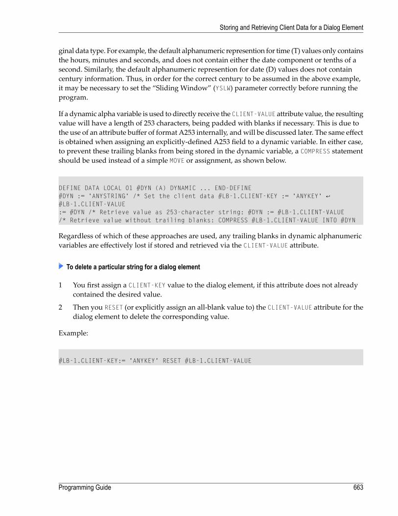
ginal data type. For example, the default alphanumeric represention for time (T) values only containsthe hours, minutes and seconds, and does not contain either the date component or tenths of asecond. Similarly, the default alphanumeric represention for date (D) values does not containcentury information. Thus, in order for the correct century to be assumed in the above example,it may be necessary to set the “Sliding Window” (YSLW) parameter correctly before running theprogram.
If a dynamic alpha variable is used to directly receive the CLIENT-VALUE attribute value, the resultingvalue will have a length of 253 characters, being padded with blanks if necessary. This is due tothe use of an attribute buffer of format A253 internally, andwill be discussed later. The same effectis obtained when assigning an explicitly-defined A253 field to a dynamic variable. In either case,to prevent these trailing blanks from being stored in the dynamic variable, a COMPRESS statementshould be used instead of a simple MOVE or assignment, as shown below.
DEFINE DATA LOCAL 01 #DYN (A) DYNAMIC ... END-DEFINE #DYN := 'ANYSTRING' /* Set the client data #LB-1.CLIENT-KEY := 'ANYKEY' ↩#LB-1.CLIENT-VALUE := #DYN /* Retrieve value as 253-character string: #DYN := #LB-1.CLIENT-VALUE /* Retrieve value without trailing blanks: COMPRESS #LB-1.CLIENT-VALUE INTO #DYN
Regardless of which of these approaches are used, any trailing blanks in dynamic alphanumericvariables are effectively lost if stored and retrieved via the CLIENT-VALUE attribute.
To delete a particular string for a dialog element
1 You first assign a CLIENT-KEY value to the dialog element, if this attribute does not alreadycontained the desired value.
2 Then you RESET (or explicitly assign an all-blank value to) the CLIENT-VALUE attribute for thedialog element to delete the corresponding value.
Example:
#LB-1.CLIENT-KEY:= 'ANYKEY' RESET #LB-1.CLIENT-VALUE
663Programming Guide
Storing and Retrieving Client Data for a Dialog Element
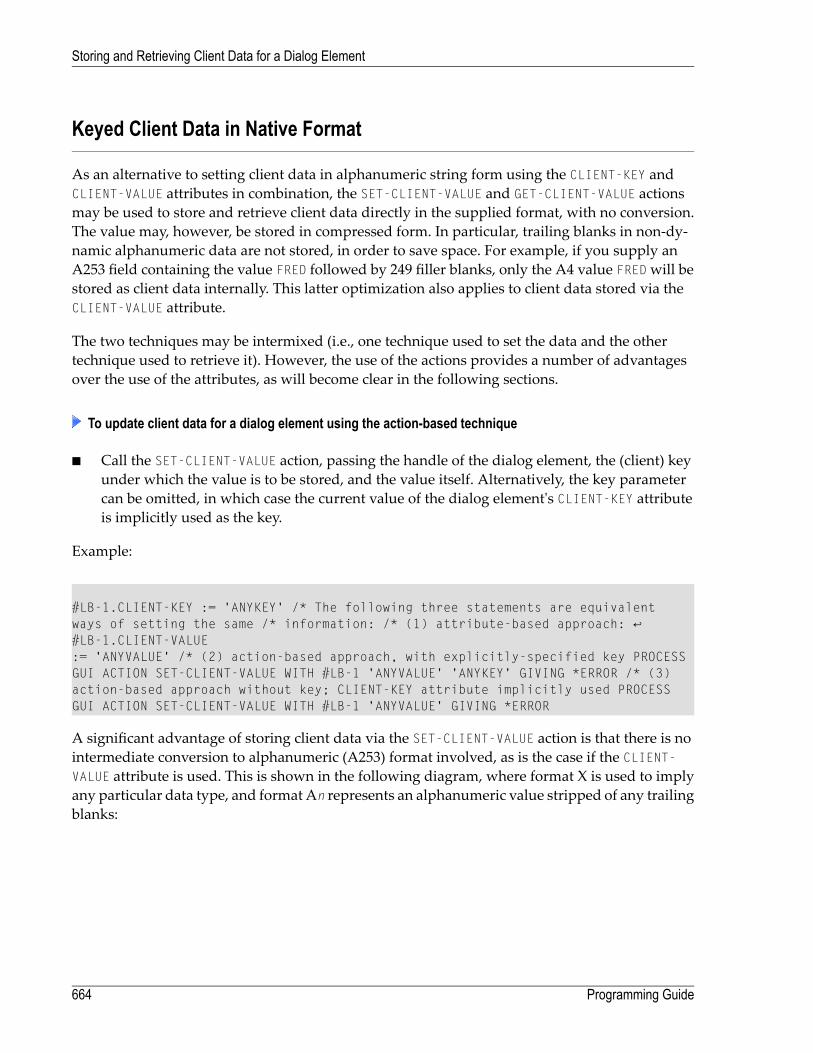
Keyed Client Data in Native Format
As an alternative to setting client data in alphanumeric string form using the CLIENT-KEY andCLIENT-VALUE attributes in combination, the SET-CLIENT-VALUE and GET-CLIENT-VALUE actionsmay be used to store and retrieve client data directly in the supplied format, with no conversion.The value may, however, be stored in compressed form. In particular, trailing blanks in non-dy-namic alphanumeric data are not stored, in order to save space. For example, if you supply anA253 field containing the value FRED followed by 249 filler blanks, only the A4 value FREDwill bestored as client data internally. This latter optimization also applies to client data stored via theCLIENT-VALUE attribute.
The two techniques may be intermixed (i.e., one technique used to set the data and the othertechnique used to retrieve it). However, the use of the actions provides a number of advantagesover the use of the attributes, as will become clear in the following sections.
To update client data for a dialog element using the action-based technique
■ Call the SET-CLIENT-VALUE action, passing the handle of the dialog element, the (client) keyunder which the value is to be stored, and the value itself. Alternatively, the key parametercan be omitted, in which case the current value of the dialog element's CLIENT-KEY attributeis implicitly used as the key.
Example:
#LB-1.CLIENT-KEY := 'ANYKEY' /* The following three statements are equivalent ways of setting the same /* information: /* (1) attribute-based approach: ↩#LB-1.CLIENT-VALUE := 'ANYVALUE' /* (2) action-based approach, with explicitly-specified key PROCESS GUI ACTION SET-CLIENT-VALUE WITH #LB-1 'ANYVALUE' 'ANYKEY' GIVING *ERROR /* (3) action-based approach without key; CLIENT-KEY attribute implicitly used PROCESS GUI ACTION SET-CLIENT-VALUE WITH #LB-1 'ANYVALUE' GIVING *ERROR
A significant advantage of storing client data via the SET-CLIENT-VALUE action is that there is nointermediate conversion to alphanumeric (A253) format involved, as is the case if the CLIENT-VALUE attribute is used. This is shown in the following diagram, where format X is used to implyany particular data type, and format An represents an alphanumeric value stripped of any trailingblanks:
Programming Guide664
Storing and Retrieving Client Data for a Dialog Element

Here we see that the storage and retrieval of client data via the CLIENT-VALUE attribute is a two-step process (as is indeed the case for all attributes in Natural) depicted by the arrows (1) and (2)above, involving an attribute buffer corresponding to the defined format for the attribute - in thiscase A253. In contrast, the use of the SET-CLIENT-VALUE and GET-CLIENT-VALUE actions is a singlestep process that is effectively equivalent to performing step (2) alone, by-passing the conversionbetween the attribute buffer and the source or target field. This offers the following advantages(aside from being somewhat faster):
■ Alphanumeric data longer than 253 characters may be stored without truncation, due to nothaving to pass through the attribute buffer.
■ Handle values may be stored. These are incompatible with the use of an alphanumeric attributebuffer, because conversions between handles and alphanumeric fields are not allowed.
■ If the data is being sourced from a dynamic alphanumeric variable, any trailing blanks are pre-served. If the attribute buffer is used, trailing blanks become indistinguishable from (and areassumed to be) buffer filler characters and are thus stripped from the value when it is stored.
■ Because the data is stored without conversion to and from alphanumeric format, non-alphanu-meric data may be stored without any loss of information. For example, date information andtenths of a second are not lost when time values are stored, and century information is not lostwhen dates are stored.
In addition, there are other advantages to using the action-based approach for client data storage:
■ Alphanumeric values consisting entirely of blanks may be stored. This is not possible via theCLIENT-VALUE attribute, as this would imply a delete operation.
■ Error codes (e.g., in the case where an invalid control handle is passed) are returned in theGIVING field (if specified), without standard error handling necessarily being invoked (althoughthis can be achieved, if desired, by the use of GIVING *ERROR).
665Programming Guide
Storing and Retrieving Client Data for a Dialog Element

To query client data for a dialog element using the action-based technique
■ Call the GET-CLIENT-VALUE action, passing the handle of the dialog element, the (client) keyfor which the value is to be retrieved, and a field to receive the value itself. Alternatively, thekey parameter can be omitted, inwhich case the current value of the dialog element's CLIENT-KEY attribute is implicitly used as the key.
Example:
DEFINE DATA LOCAL 01 #VALUE (A253) ... END-DEFINE PROCESS GUI ACTION GET-CLIENT-VALUEWITH #LB-1 #VALUE 'ANYKEY' GIVING *ERROR IF #VALUE <> ' ' /* Value found ... ELSE/* Value not found ... END-IF
Note that the format of the field specified to receive the value must be MOVE-compatible with theformat of the stored value.
If the specified key is not found for the specified dialog element, the value field is RESET. For ex-ample, an alphanumeric receiving field is filled with blanks, and a numeric receiving field is setto zero.
However, if such values can be explicitly stored for this key by the program, the value alone cannotbe used to determine whether the requested client data was found.
To query client data if resetted values are being explicitly stored
■ Call the GET-CLIENT-VALUE action, also passing (in addition to the standard parametersmentioned above) a field of type L to receive the found/not found status.
Example:
DEFINE DATA LOCAL 01 #VALUE (A253) 01 #FOUND (L) ... END-DEFINE * PROCESS GUIACTION GET-CLIENT-VALUE WITH #LB-1 #VALUE 'ANYKEY' #FOUND GIVING *ERROR * IF #FOUND... END-IF
Themain advantage of reading client data via the GET-CLIENT-VALUE action is again the avoidanceof going via an attribute buffer (see earlier diagram), implying that no intermediate conversion toor from alphanumeric (A253) format involved, as is the case if the CLIENT-VALUE attribute is used.Instead, the stored data is converted directly to the format of the receiving field for the value. Thisoffers the following advantages:
■ Alphanumeric data longer than 253 characters may be retrieved, without being truncated to thelength of the (not used) CLIENT-VALUE attribute buffer.
■ Handle values may be retrieved, which are not MOVE-compatible with the alphanumeric formatof the CLIENT-VALUE attribute buffer.
Programming Guide666
Storing and Retrieving Client Data for a Dialog Element

■ If the data is being read into a dynamic alphanumeric variable, any trailing blanks in stored al-phanumeric data are preserved. If the CLIENT-VALUE attribute is used, the dynamic variablewould receive the buffer's filler characters and be unable to distinguish them from any trailingblanks in the original data.
In addition, Stored alphanumeric values consisting entirely of blanks may be recognized. This isnot possible via the CLIENT-VALUE attribute, as there is noway to distinguish them from the implicit“not found” value.
To delete client data for a dialog element using the action-based technique
■ Call the SET-CLIENT-VALUE action, passing the handle of the dialog element and the (client)key for which the value is to be deleted, but omitting the value itself. Alternatively, the keyparameter can be omitted, in which case the current value of the dialog element's CLIENT-KEYattribute is implicitly used as the key.
Example:
/* No value supplied => delete any existing value for specified key PROCESS GUIACTION SET-CLIENT-VALUE WITH #LB-1 1X 'ANYKEY' GIVING *ERROR /* Alternatively,a mixed attribute/action approach can be used: #LB-1.CLIENT-KEY := 'ANYKEY' PROCESSGUI ACTION SET-CLIENT-VALUE WITH #LB-1 GIVING *ERROR
Key Enumeration
The above sections have dealt with the creation, updating, querying and deletion of client key andclient value data. Inmost cases this is enough. However, in some situations, the keys that are beingused by a dialog element are either not known to the code that reads them, or it is necessary to beable to verify that the expected keys are present for debugging or testing purposes. The iterativeprocess of retrieving the keys currently being used by a particular dialog element is known as keyenumeration.
To enumerate the client keys for a dialog element
1 Call the ENUM-CLIENT-KEYS action, passing the handle of the dialog element for which theclient keys should be enumerated, but omitting the key parameter. This has the effect of reset-ting the dialog element's enumeration cursor (i.e., position) back to the beginning of its internalkey list. Since the enumeration cursor is initially reset when a dialog element is created, thisstep is strictly not required for the first key enumeration for a particular dialog element.However, it is good practice to explicitly reset the cursor in this manner, in order to make theenumeration context-insensitive.
667Programming Guide
Storing and Retrieving Client Data for a Dialog Element
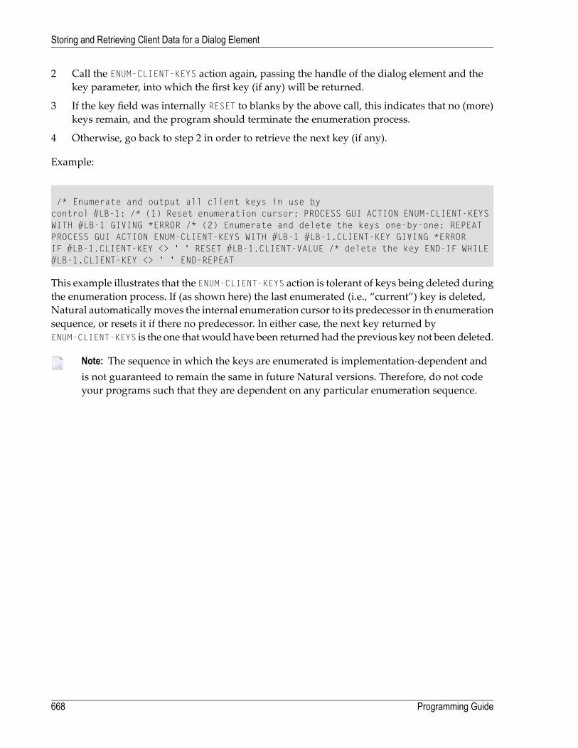
2 Call the ENUM-CLIENT-KEYS action again, passing the handle of the dialog element and thekey parameter, into which the first key (if any) will be returned.
3 If the key field was internally RESET to blanks by the above call, this indicates that no (more)keys remain, and the program should terminate the enumeration process.
4 Otherwise, go back to step 2 in order to retrieve the next key (if any).
Example:
/* Enumerate and output all client keys in use bycontrol #LB-1: /* (1) Reset enumeration cursor: PROCESS GUI ACTION ENUM-CLIENT-KEYSWITH #LB-1 GIVING *ERROR /* (2) Enumerate and delete the keys one-by-one: REPEATPROCESS GUI ACTION ENUM-CLIENT-KEYS WITH #LB-1 #LB-1.CLIENT-KEY GIVING *ERRORIF #LB-1.CLIENT-KEY <> ' ' RESET #LB-1.CLIENT-VALUE /* delete the key END-IF WHILE#LB-1.CLIENT-KEY <> ' ' END-REPEAT
This example illustrates that the ENUM-CLIENT-KEYS action is tolerant of keys being deleted duringthe enumeration process. If (as shown here) the last enumerated (i.e., “current”) key is deleted,Natural automaticallymoves the internal enumeration cursor to its predecessor in th enumerationsequence, or resets it if there no predecessor. In either case, the next key returned byENUM-CLIENT-KEYS is the one thatwould have been returned had the previous key not been deleted.
Note: The sequence in which the keys are enumerated is implementation-dependent andis not guaranteed to remain the same in future Natural versions. Therefore, do not codeyour programs such that they are dependent on any particular enumeration sequence.
Programming Guide668
Storing and Retrieving Client Data for a Dialog Element
82 Creating Dialog Elements on a Canvas Control
You can use a canvas control as a background to draw the following dialog elements on it: therectangle, line and graphictext controls. These dialog elements “visualize” information. You can,for example, create three or four rectangle controls, fill them with color and change their size atruntime. This way, you can build your own bar chart.
Once you have created a canvas control in the dialog, you can go on to create the rectangle, lineand graphictext controls in it.
Note: Graphictext controls do not repaint the background of the rectangle in which theyare located. The background of the rectangle is specified at creation time of the graphictextcontrol. What they do repaint is only the text specified in the text attribute.
To create dialog elements on a canvas control
■ Use the PROCESS GUI statement action ADD.
The rectangle, line and graphictext controls are then displayed inside the borders of the canvascontrol; if they exceed the canvas borders, they are clipped.
The following attributes are useful for controlling the behavior of the canvas control and the dialogelements on it:
■ OFFSET-X and OFFSET-Y determine the x and y axis offset of the canvas control's upper borderagainst the upper border of the area by which the rectangle, line or graphictext control haveexceeded the canvas control's borders.
■ RECTANGLE-X, RECTANGLE-Y, RECTANGLE-W and RECTANGLE-H determine the size of a rectanglecontrol and its position relative to the underlying canvas control.
■ P1-X, P1-Y, P2-X and P2-Y determine the start position (P1xx) and the end position (P2xx) of aline control relative to the underlying canvas control.
The following example illustrates how to create a canvas control
669

/* In the dialog's local data area, the following must be defined:01 #CNV1 HANDLE OF CANVAS01 #XAX HANDLE OF LINE01 #YAX HANDLE OF LINE01 #H1 HANDLE OF RECTANGLE01 #H2 HANDLE OF RECTANGLE01 #H3 HANDLE OF RECTANGLE01 #H4 HANDLE OF RECTANGLE01 #RESPONSE (I4)/* In the dialog's AFTER-OPEN event handler, the following must be defined:PROCESS GUI ACTION ADD WITHPARAMETERS
PARENT = #DLG$WINDOWTYPE = CANVASHANDLE-VARIABLE = #CNV1RECTANGLE-X = 20RECTANGLE-Y = 20RECTANGLE-W = 200RECTANGLE-H = 200STYLE = 'F'
END-PARAMETERSGIVING RESPONSEPROCESS GUI ACTION ADD WITHPARAMETERS
PARENT = #CNV1TYPE = LINEHANDLE-VARIABLE = #YAXSTYLE = 'S'P1-X = 20P1-Y = 20P2-X = 20P2-Y = 180
END-PARAMETERSGIVING RESPONSEPROCESS GUI ACTION ADD WITHPARAMETERS
PARENT = #CNV1TYPE = LINEHANDLE-VARIABLE = #XAXP1-X = 180P1-Y = 180P2-X = 20P2-Y = 180
END-PARAMETERSGIVING RESPONSEPROCESS GUI ACTION ADD WITHPARAMETERS
PARENT = #CNV1TYPE = RECTANGLEHANDLE-VARIABLE = #H1RECTANGLE-X = 20
Programming Guide670
Creating Dialog Elements on a Canvas Control

RECTANGLE-Y = 180RECTANGLE-H = 20RECTANGLE-W = -60FOREGROUND-COLOUR-NAME = BLACKBACKGROUND-COLOUR-NAME = RED
END-PARAMETERSGIVING RESPONSEPROCESS GUI ACTION ADD WITHPARAMETERS
PARENT = #CNV1TYPE = RECTANGLEHANDLE-VARIABLE = #H2RECTANGLE-X = 40RECTANGLE-Y = 180RECTANGLE-H = 20RECTANGLE-W = -40FOREGROUND-COLOUR-NAME = BLACKBACKGROUND-COLOUR-NAME = BLUE
END-PARAMETERSGIVING RESPONSEPROCESS GUI ACTION ADD WITH PARAMETERS
PARENT = #CNV1TYPE = RECTANGLEHANDLE-VARIABLE = #H3RECTANGLE-X = 60RECTANGLE-Y = 180RECTANGLE-H = 20RECTANGLE-W = -55FOREGROUND-COLOUR-NAME = BLACKBACKGROUND-COLOUR-NAME = GREEN
END-PARAMETERSGIVING RESPONSEPROCESS GUI ACTION ADD WITHPARAMETERS
PARENT = #CNV1TYPE = RECTANGLEHANDLE-VARIABLE = #H4RECTANGLE-X = 80RECTANGLE-Y = 180RECTANGLE-H = 20RECTANGLE-W = -80FOREGROUND-COLOUR-NAME = BLACKBACKGROUND-COLOUR-NAME = MAGENTA
END-PARAMETERSGIVING RESPONSE
671Programming Guide
Creating Dialog Elements on a Canvas Control

672

83 Label Editing in Tree View and List View Controls
■ Introduction .................................................................................................................................. 674■ Label Editing ................................................................................................................................. 674■ Changing an Item's Label Programmatically ........................................................................................ 676
673

Introduction
This section describes the process of editing item labels for both tree view and list view controls.The word “item” is therefore used throughout, in place of “tree view item” and “list view item”,respectively.
Label Editing
The editing of an item's label, unless prohibited (see below), may be initiated in one of three ways:
1. By the user, by clicking on the label of a selected item.
2. By the user, by pressing the F2 key (whereupon the itemwith the focus rectangle, if any, is edited).
3. By the program, by calling the EDIT-LABEL action.
Regardless of the means of initiation, the sequence of actions taken by Natural in response isidentical:
1. The control's MODIFIABLE attribute is examined. If this is FALSE (e.g., theModifiable optionwasnot checked in the control's attributeswindow), no further action occurs and label editingmodeis not entered.
2. The control's ITEM attribute is set to the handle of the item forwhich label editingwas requested(the “target” item).
3. Unless suppressed, a BEFORE-EDIT event is raised for the control.
4. The target item's MODIFIABLE attribute is examined. If this is FALSE, no further action occursand label editing mode is not entered.
5. Label editing mode is entered. The user may cancel any changes he has made via the ESC key.In this case, the original label is restored, edit mode exited, and no further action taken. Altern-atively, the user can commit the changes (e.g. by pressing the ENTER key or setting the focus toanother window or control).
6. The target item's STRING attribute is updated with the new label text.
7. Unless suppressed, an AFTER-EDIT event is raised for the control.
8. If the item's label is no longer identical to the item's STRING attribute (i.e., the application mod-ified the attribute during the AFTER-EDIT event), the item's label is updated accordingly.
The purpose of the BEFORE-EDIT event is twofold. Firstly, it allows the application to dynamicallyset the item's MODIFIABLE attribute (thus allowing or preventing label editing from taking place)according to the particular context. Secondly, it gives the application a chance to save the originallabel in case it wishes to restore it later in the AFTER-EDIT event.
Programming Guide674
Label Editing in Tree View and List View Controls

The AFTER-EDIT event has four options:
1. Do nothing, which case the new item label will be accepted.
2. Reject the new label, by restoring the previous value for the item's STRING attribute (as savedin the BEFORE-EDIT event).
3. Reject the new label, by setting the the item's STRING attribute to some other value that neithermatches the new nor old label (e.g. silently “correcting” the label entered by the user).
4. Re-enter edit mode for the item, forcing the user to modify the label again (possibly after dis-playing a message box to inform the user that the newly entered label is invalid).
As an example demonstrating some of the above topics, consider the following example. Firstly,we define some local data variables which we will need later:
01 #CONTROL HANDLE OF GUI 01 #ITEM HANDLE OF GUI01 #LABEL (A) DYNAMIC 01 #POS (I4)
Having done this, we can canwrite a trivial BEFORE-EDIT event, wherewe simply save the existinglabel of the item about to be edited in the dynamic variable #LABEL:
#CONTROL := *CONTROL #ITEM := #CONTROL.ITEM #LABEL:= #ITEM.STRING
To illustrate a few of the above techniques, we use the following AFTER-EDIT handler:
#CONTROL := *CONTROL #ITEM := #CONTROL.ITEM IF#ITEM.STRING = ' ' #ITEM.STRING := #LABEL ELSE EXAMINE #ITEM.STRING TRANSLATEINTO LOWER EXAMINE #ITEM.STRING FOR ' ' GIVING POSITION #POS IF #POS > 0 PROCESSGUI ACTION CALL-DIALOG WITH #DLG$WINDOW #ITEM 'EDIT-LABEL' FALSE END-IF END-IF
The above code performs the following actions:
1. If the new item label consists only of blank, the old item label, as saved in the BEFORE-EDITevent is restored.
2. Otherwise, the new item label is converted into lower case (EXAMINE TRANSLATE).
3. Then, if the new item label contains a blank, we treat the data as invalid and raise an asynchron-ous user-defined event for the item in order to request corrected data from the user (more later).
The asynchronous event allows an invalid item label to be provisionally accepted. However, onreceipt of the user-defined EDIT-LABEL event, we display a message box to inform the user thatthe data is invalid and in need of correction, then re-enter label editing mode. This is done via thefollowing code in the DEFAULT event handler for the dialog:
675Programming Guide
Label Editing in Tree View and List View Controls

IF *EVENT = 'EDIT-LABEL' #ITEM := *CONTROL OPEN DIALOG NGU-MESSAGEBOX USING #ITEM.PARENT WITH #BUTTON 'Invalid data - please ↩re-enter' 'Label Edit' '!O' PROCESS GUI ACTION EDIT-LABEL WITH #ITEM GIVING *ERROR END-IF
If it is sufficient to set an edit mask and/or maximum label length in characters, and/or specifythat only upper case characters should be allowed, this can be achieved without any coding bysetting the EDIT-MASK attribute, LENGTH attribute or Upper case (U) STYLE flag (respectively) forthe appropriate item(s). If an edit mask is specified, Natural automatically restores the old label,issuing a beep (if enabled), if the entered label does not match the mask.
Changing an Item's Label Programmatically
An item's label may be set directly via its STRING attribute. For example:
#ITEM.STRING := New label'
where #ITEM is the handle of the corresponding tree view or list view item.
In this case, only the item's edit mask (if any) is used. All other aspects of label editing describedabove do not apply here. In particular:
1. The label is changed regardless of the value of the MODIFIABLE attribute for the control and theitem.
2. No BEFORE-EDIT or AFTER-EDIT events are raised.
3. The control's ITEM attribute is not set.
4. The text is not automatically translated to upper case if the item's Upper case (U) STYLE flag isset.
5. The supplied label can exceed the limit (if any) imposed by the item's LENGTH attribute.
Programming Guide676
Label Editing in Tree View and List View Controls
84 Working with ActiveX Controls
■ Terminology .................................................................................................................................. 678■ How To Define an ActiveX Control ..................................................................................................... 678■ How To Create an ActiveX Control .................................................................................................... 678■ Accessing Simple Properties ............................................................................................................ 679■ Colors ......................................................................................................................................... 680■ Pictures ....................................................................................................................................... 681■ Fonts .......................................................................................................................................... 681■ Variants ....................................................................................................................................... 683■ Arrays ......................................................................................................................................... 684■ Using the PROCESS GUI Statement ................................................................................................. 684
677
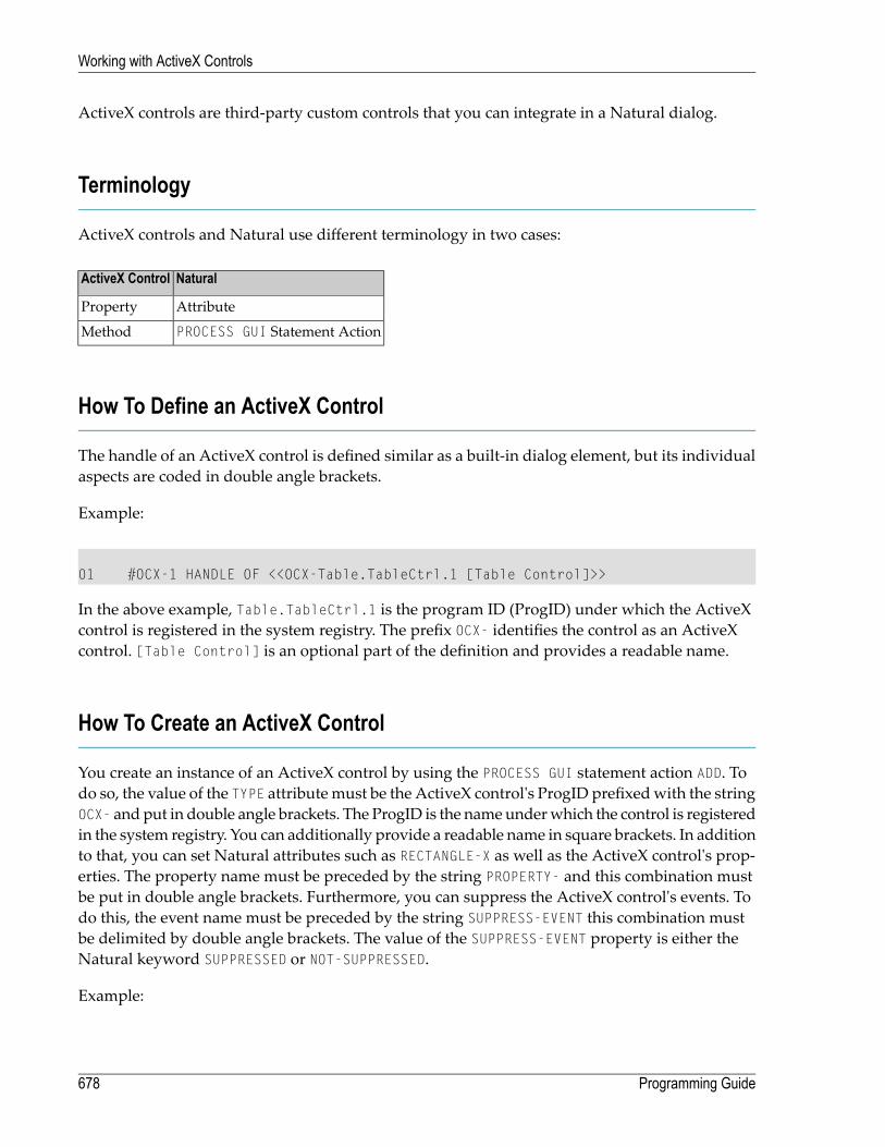
ActiveX controls are third-party custom controls that you can integrate in a Natural dialog.
Terminology
ActiveX controls and Natural use different terminology in two cases:
NaturalActiveX Control
AttributeProperty
PROCESS GUI Statement ActionMethod
How To Define an ActiveX Control
The handle of an ActiveX control is defined similar as a built-in dialog element, but its individualaspects are coded in double angle brackets.
Example:
01 #OCX-1 HANDLE OF <<OCX-Table.TableCtrl.1 [Table Control]>>
In the above example, Table.TableCtrl.1 is the program ID (ProgID) under which the ActiveXcontrol is registered in the system registry. The prefix OCX- identifies the control as an ActiveXcontrol. [Table Control] is an optional part of the definition and provides a readable name.
How To Create an ActiveX Control
You create an instance of an ActiveX control by using the PROCESS GUI statement action ADD. Todo so, the value of the TYPE attributemust be the ActiveX control's ProgID prefixedwith the stringOCX- and put in double angle brackets. The ProgID is the nameunderwhich the control is registeredin the system registry. You can additionally provide a readable name in square brackets. In additionto that, you can set Natural attributes such as RECTANGLE-X as well as the ActiveX control's prop-erties. The property name must be preceded by the string PROPERTY- and this combination mustbe put in double angle brackets. Furthermore, you can suppress the ActiveX control's events. Todo this, the event name must be preceded by the string SUPPRESS-EVENT this combination mustbe delimited by double angle brackets. The value of the SUPPRESS-EVENT property is either theNatural keyword SUPPRESSED or NOT-SUPPRESSED.
Example:
Programming Guide678
Working with ActiveX Controls

PROCESS GUI ACTION ADDWITH PARAMETERS
HANDLE-VARIABLE = #OCX-1TYPE = <<OCX-Table.TableCtrl.1 [Table Control]>>PARENT = #DLG$WINDOWRECTANGLE-X = 44RECTANGLE-Y = 31RECTANGLE-W = 103RECTANGLE-H = 46<<PROPERTY-HeaderColor>> = H'FF0080'<<PROPERTY-Rows>> = 16<<PROPERTY-Columns>> = 4<<SUPPRESS-EVENT-RowMoved>> = SUPPRESSED<<SUPPRESS-EVENT-ColMoved>> = SUPPRESSED
END-PARAMETERS
Accessing Simple Properties
Simple properties are properties that do not have parameters. Simple properties of an ActiveXcontrol are addressed like attributes of built-in controls. The attribute name is built by prefixingthe property namewith PROPERTY- and enclosing it in angle brackets.The properties of anActiveXcontrol are displayed in the Component Browser. The following examples assume that theActiveXcontrol #OCX-1 has the simple properties CurrentRow and CurrentCol.
Example:
* Get the value of a property.#MYROW := #OCX-1.<<PROPERTY-CurrentRow>>* Put the value of a property.#OCX-1.<<PROPERTY-CurrentCol>> := 17
The data types of ActiveX control properties are those defined by OLE Automation. In Natural,each of these data types is mapped to a corresponding Natural data type. The following tableshows which OLE Automation data type is mapped to which Natural data type.
NATURAL data typeOLE Automation data type
LVT_BOOL
A dynamicVT_BSTR
P15.4VT_CY
TVT_DATE
Pn.mVT_DECIMAL
HANDLE OF OBJECTVT_DISPATCH
679Programming Guide
Working with ActiveX Controls

NATURAL data typeOLE Automation data type
I4VT_ERROR
I2VT_I1
I2VT_I2
I4VT_I4
I4VT_INT
F4VT_R4
F8VT_R8
B1VT_U1
B2VT_U2
B4VT_U4
B4VT_UINT
HANDLE OF OBJECTVT_UNKNOWN
(any Natural data type)VT_VARIANT
B3OLE_COLOR (VT_UI4)
VT_FONT (VT_DISPATCH IFontDisp*) HANDLE OF FONTHANDLE OF OBJECT (IFontDisp*)A dynamic
VT_PICTURE (VT_DISPATCH IPictureDisp*) HANDLE OF OBJECT (IPictureDisp*)A dynamic
Read the table in the following way: Assume an ActiveX control #OCX-1 has a property named"Size", which is of type VT_R8. Then the expression #OCX-1.<<PROPERTY-SIZE>> has the type F8in Natural.
Note: The Component Browser displays the corresponding Natural data types directly.
Some special data types are considered individually in the following:
Colors
A property of type Color appears in Natural as a B3 value. The B3 value is interpreted as an RGBcolor value. The three bytes contain the red, green and blue elements of the color, respectively.Thus for exampleH'FF0000' corresponds to red,H'00FF00' corresponds to green,H'0000FF' corres-ponds to blue and so on.
Example:
Programming Guide680
Working with ActiveX Controls
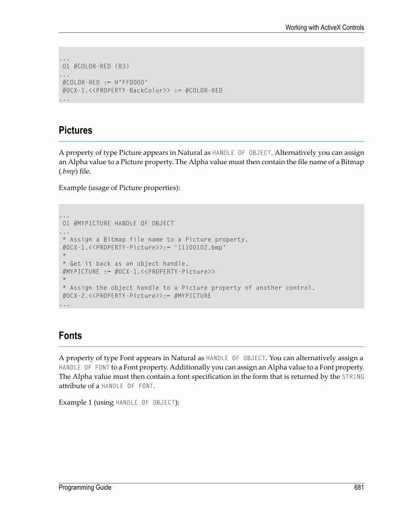
...01 #COLOR-RED (B3)...#COLOR-RED := H'FF0000'#OCX-1.<<PROPERTY-BackColor>> := #COLOR-RED...
Pictures
A property of type Picture appears in Natural as HANDLE OF OBJECT. Alternatively you can assignan Alpha value to a Picture property. The Alpha valuemust then contain the file name of a Bitmap(.bmp) file.
Example (usage of Picture properties):
...01 #MYPICTURE HANDLE OF OBJECT...* Assign a Bitmap file name to a Picture property.#OCX-1.<<PROPERTY-Picture>>:= '11100102.bmp'** Get it back as an object handle.#MYPICTURE := #OCX-1.<<PROPERTY-Picture>>** Assign the object handle to a Picture property of another control.#OCX-2.<<PROPERTY-Picture>>:= #MYPICTURE...
Fonts
A property of type Font appears in Natural as HANDLE OF OBJECT. You can alternatively assign aHANDLE OF FONT to a Font property. Additionally you can assign anAlpha value to a Font property.The Alpha value must then contain a font specification in the form that is returned by the STRINGattribute of a HANDLE OF FONT.
Example 1 (using HANDLE OF OBJECT):
681Programming Guide
Working with ActiveX Controls
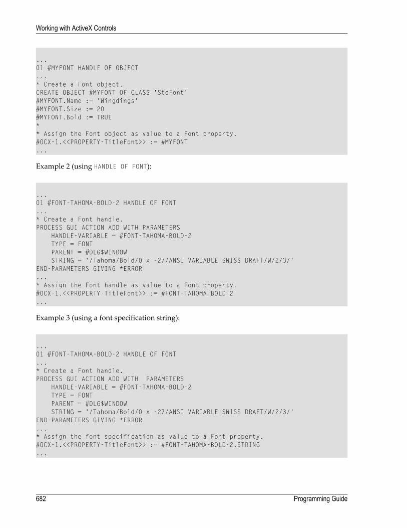
...01 #MYFONT HANDLE OF OBJECT...* Create a Font object.CREATE OBJECT #MYFONT OF CLASS 'StdFont'#MYFONT.Name := 'Wingdings'#MYFONT.Size := 20#MYFONT.Bold := TRUE** Assign the Font object as value to a Font property.#OCX-1.<<PROPERTY-TitleFont>> := #MYFONT...
Example 2 (using HANDLE OF FONT):
...01 #FONT-TAHOMA-BOLD-2 HANDLE OF FONT...* Create a Font handle.PROCESS GUI ACTION ADD WITH PARAMETERS
HANDLE-VARIABLE = #FONT-TAHOMA-BOLD-2TYPE = FONTPARENT = #DLG$WINDOWSTRING = '/Tahoma/Bold/0 x -27/ANSI VARIABLE SWISS DRAFT/W/2/3/'
END-PARAMETERS GIVING *ERROR...* Assign the Font handle as value to a Font property.#OCX-1.<<PROPERTY-TitleFont>> := #FONT-TAHOMA-BOLD-2...
Example 3 (using a font specification string):
...01 #FONT-TAHOMA-BOLD-2 HANDLE OF FONT...* Create a Font handle.PROCESS GUI ACTION ADD WITH PARAMETERS
HANDLE-VARIABLE = #FONT-TAHOMA-BOLD-2TYPE = FONTPARENT = #DLG$WINDOWSTRING = '/Tahoma/Bold/0 x -27/ANSI VARIABLE SWISS DRAFT/W/2/3/'
END-PARAMETERS GIVING *ERROR...* Assign the font specification as value to a Font property.#OCX-1.<<PROPERTY-TitleFont>> := #FONT-TAHOMA-BOLD-2.STRING...
Programming Guide682
Working with ActiveX Controls

Variants
A property of type Variant is compatible with any Natural data type. This means that the type ofthe expression #OCX-1.<<PROPERTY-Value>> is not checked by the compiler, if "Value" is a propertyof type Variant. So the assignments #OCX-1.<<PROPERTY-Value >> := #MYVAL and #MYVAL :=#OCX-1.<<PROPERTY-Value >> are allowed independently of the type of the variable #MYVAL. It ishowever up to the ActiveX control to accept or reject a particular property value at runtime, or todeliver the value in the requested format. If it does not, the ActiveX control will usually raise anexception. This exception is returned as a Natural error code to the Natural program. Here it canbe handled in the usual way in an ON ERROR block. You should check the documentation of theActiveX control to find out which data formats are actually allowed for a particular property oftype Variant.
An expression like #OCX-1.<<PROPERTY-Value>> (where "Value" is a Variant property) can occuras source operand in any statement. However, it can be used as target operand only in assignmentstatements.
Examples (usage of Variant properties):
(Assume that "Value" is a property of type Variant of the ActiveX control #OCX-1)
...01 #STR1 (A100)01 #STR2 (A100)...* These statements are allowed, because the Variant property is used* as source operand (its value is read).#STR1 := #OCX-1.<<PROPERTY-Value>>COMPRESS #OCX-1.<<PROPERTY-Value>> 'XYZ' to #STR2...* This leads to an error at compiletime, because the Variant* property is used as target operand (its value is modified) in* a statement other than an assignment.COMPRESS #STR1 "XYZ" to #OCX-1.<<PROPERTY-Value>>...* This statement is allowed, because the Variant property is used* as target operand in an assignment.COMPRESS #STR1 'XYZ' to #STR2#OCX-1.<<PROPERTY-Value>> := #STR2...
683Programming Guide
Working with ActiveX Controls

Arrays
A property of type SAFEARRAY of up to three dimensions appears in a Natural program as anarray with the same dimension count, occurrence count per dimension and the correspondingformat. (Properties of type SAFEARRAY with more than three dimensions cannot be used inNatural programs.) The dimension and occurrence count of an array property is not determinedat compiletime but only at runtime. This is because this information is variable and is not definedat compiletime. The format however is checked at compiletime.
Array properties are always accessed as a whole. So no index notation is necessary and allowedwith an array property.
Examples (usage of Array properties):
(Assume that "Values" is a property of the ActiveX control #OCX-1 an has the type SAFEARRAYof VT_I4)
...01 #VAL-L (L/1:10)01 #VAL-I (I4/1:10)...* This statement is allowed, because the format of the property* is data transfer compatible with the format of the receiving array.* However, if it turns out at runtime that the dimension count or* occurrence count per dimension do not match, a runtime error will* occur.VAL-I(*) := #OCX-1.<<PROPERTY-Values>>...* This statement leads to an error at compiletime, because* the format of the property is not data transfer compatible with* the format of the receiving array.VAL-L(*) := #OCX-1.<<PROPERTY-Values>>...
Using the PROCESS GUI Statement
Themethods of ActiveX controls are called as actions in a PROCESS GUI statement. The same is thecase with the complex properties of ActiveX controls (i. e. properties that have parameters). Themethods and properties of an ActiveX control are displayed in the Component Browser.
This section covers the following topics:
■ Performing Methods■ Getting Property Values
Programming Guide684
Working with ActiveX Controls

■ Putting Property Values■ Optional Parameters■ Error Handling■ Using Events With Parameters■ Suppressing Events At Runtime
Performing Methods
To perform a method of an ActiveX control the PROCESS GUI statement is used. The name of thecorresponding PROCESS GUI action is built by prefixing themethod namewith METHOD- and enclos-ing it in angle brackets. The ActiveX control handle and themethod parameters (if any) are passedin the WITH clause of the PROCESS GUI statement. The return value of themethod (if any) is receivedin the variable specified in the USING clause of the PROCESS GUI statement.
This means: To perform a method, you enter a statement
PROCESS GUI ACTION <<METHOD-methodname>> WITHhandlename [parameter]...
[USING method-return-operand]..
Examples:
* Performing a method without parameters:PROCESS GUI ACTION <<METHOD-AboutBox>> WITH #OCX-1* Performing a method with parameters:PROCESS GUI ACTION <<METHOD-CreateItem>> WITH #OCX-1 #ROW #COL #TEXT* Performing a method with parameters and a return value:PROCESS GUI ACTION <<METHOD-RemoveItem>> WITH #OCX-1 #ROW #COL USING #RETURN
Formats and length of the method parameters and the return value are checked at compiletimeagainst the definition of the method, as it is displayed in the Component Browser.
Getting Property Values
To get the value of a property that has parameters, the name of the corresponding PROCESS GUIaction is built by prefixing the property name with GET-PROPERTY- and enclosing it in anglebrackets. The ActiveX control handle and the property parameters (if any) are passed in the WITHclause of the PROCESS GUI statement. The property value is received in the USING clause of thePROCESS GUI statement.
This means: To get the value of a property that has parameters, you enter a statement
685Programming Guide
Working with ActiveX Controls
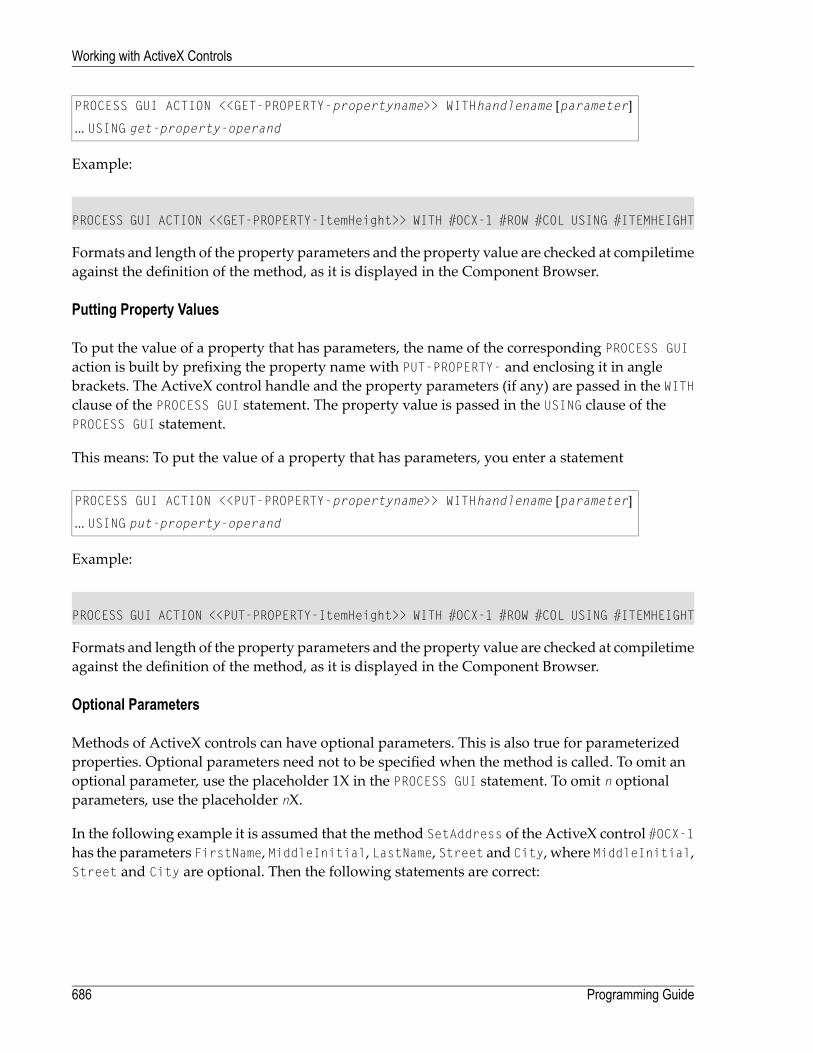
PROCESS GUI ACTION <<GET-PROPERTY-propertyname>> WITHhandlename [parameter]
... USING get-property-operand
Example:
PROCESS GUI ACTION <<GET-PROPERTY-ItemHeight>> WITH #OCX-1 #ROW #COL USING #ITEMHEIGHT
Formats and length of the property parameters and the property value are checked at compiletimeagainst the definition of the method, as it is displayed in the Component Browser.
Putting Property Values
To put the value of a property that has parameters, the name of the corresponding PROCESS GUIaction is built by prefixing the property name with PUT-PROPERTY- and enclosing it in anglebrackets. The ActiveX control handle and the property parameters (if any) are passed in the WITHclause of the PROCESS GUI statement. The property value is passed in the USING clause of thePROCESS GUI statement.
This means: To put the value of a property that has parameters, you enter a statement
PROCESS GUI ACTION <<PUT-PROPERTY-propertyname>> WITHhandlename [parameter]
... USING put-property-operand
Example:
PROCESS GUI ACTION <<PUT-PROPERTY-ItemHeight>> WITH #OCX-1 #ROW #COL USING #ITEMHEIGHT
Formats and length of the property parameters and the property value are checked at compiletimeagainst the definition of the method, as it is displayed in the Component Browser.
Optional Parameters
Methods of ActiveX controls can have optional parameters. This is also true for parameterizedproperties. Optional parameters need not to be specified when the method is called. To omit anoptional parameter, use the placeholder 1X in the PROCESS GUI statement. To omit n optionalparameters, use the placeholder nX.
In the following example it is assumed that the method SetAddress of the ActiveX control #OCX-1has the parameters FirstName, MiddleInitial, LastName, Street and City, where MiddleInitial,Street and City are optional. Then the following statements are correct:
Programming Guide686
Working with ActiveX Controls
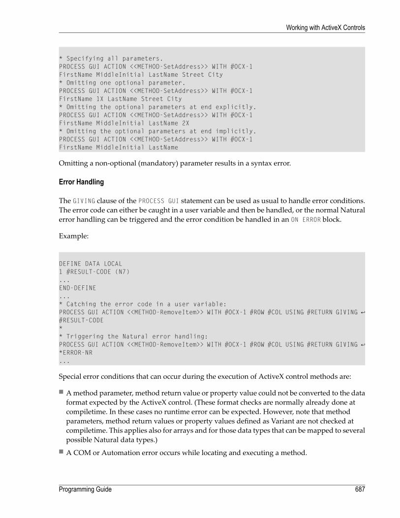
* Specifying all parameters.PROCESS GUI ACTION <<METHOD-SetAddress>> WITH #OCX-1FirstName MiddleInitial LastName Street City* Omitting one optional parameter.PROCESS GUI ACTION <<METHOD-SetAddress>> WITH #OCX-1FirstName 1X LastName Street City* Omitting the optional parameters at end explicitly.PROCESS GUI ACTION <<METHOD-SetAddress>> WITH #OCX-1FirstName MiddleInitial LastName 2X* Omitting the optional parameters at end implicitly.PROCESS GUI ACTION <<METHOD-SetAddress>> WITH #OCX-1FirstName MiddleInitial LastName
Omitting a non-optional (mandatory) parameter results in a syntax error.
Error Handling
The GIVING clause of the PROCESS GUI statement can be used as usual to handle error conditions.The error code can either be caught in a user variable and then be handled, or the normal Naturalerror handling can be triggered and the error condition be handled in an ON ERROR block.
Example:
DEFINE DATA LOCAL1 #RESULT-CODE (N7)...END-DEFINE...* Catching the error code in a user variable:PROCESS GUI ACTION <<METHOD-RemoveItem>> WITH #OCX-1 #ROW #COL USING #RETURN GIVING ↩#RESULT-CODE** Triggering the Natural error handling:PROCESS GUI ACTION <<METHOD-RemoveItem>> WITH #OCX-1 #ROW #COL USING #RETURN GIVING ↩*ERROR-NR...
Special error conditions that can occur during the execution of ActiveX control methods are:
■ Amethod parameter, method return value or property value could not be converted to the dataformat expected by the ActiveX control. (These format checks are normally already done atcompiletime. In these cases no runtime error can be expected. However, note that methodparameters, method return values or property values defined as Variant are not checked atcompiletime. This applies also for arrays and for those data types that can bemapped to severalpossible Natural data types.)
■ A COM or Automation error occurs while locating and executing a method.
687Programming Guide
Working with ActiveX Controls

■ The ActiveX control raises an exception during the execution of a method.
In these cases the error message contains further information provided by the ActiveX control,which can be used to determine the reason of the error with the help of the documentation of theActiveX control.
Using Events With Parameters
Events sent by ActiveX controls can have parameters. In the controls event-handler sections, theseparameters can be queried. Parameters passed by reference can also be modified. The events ofan ActiveX control, the names and data types of the parameters and the fact if a parameter ispassed by value or by reference is all displayed in the Component Browser.
Event parameters of an ActiveX control are addressed like attributes of built-in controls. The at-tribute name is built by prefixing the parameter name with PARAMETER- and enclosing it in anglebrackets. Alternatively, parameters can be addressed by position. This means the attribute nameis built by prefixing the number of the parameter with PARAMETER- and enclosing it in anglebrackets. The first parameter of an event has the number 1, the second the number 2 and so on.These attribute names are only valid inside the event handler of that particular event.
In the following examples it is assumed that a particular event of the ActiveX control #OCX-1 hasthe parameters KeyCode and Cancel. Then the event handler of that event might contain the fol-lowing statements:
* Querying a parameter by name:#PRESSEDKEY := #OCX-1.<<PARAMETER-KeyCode>>* Querying a parameter by position:#PRESSEDKEY := #OCX-1.<<PARAMETER-1>>
Parameters that are passed by reference can be modified in the event handler. In the followingexample it is assumed that the Cancel parameter is passed by reference and is thus modifiable.Then the event handler might contain the following statements:
* Modifying a parameter by name:#OCX-1.<<PARAMETER-Cancel>>:= TRUE* Modifying a parameter by position:#OCX-1.<<PARAMETER-2>>:= TRUE
Programming Guide688
Working with ActiveX Controls

Suppressing Events At Runtime
To suppress or unsuppress an event of an ActiveX control at runtime, modify the correspondingsuppress event attribute of the control. The name of the suppress event attribute is built by prefixingthe event namewith SUPPRESS-EVENT- and enclosing it in angle brackets. The events of anActiveXcontrol are displayed in the Component Browser.
The following example assumes that the ActiveX control #OCX-1 has the event ColMoved.
* Suppress the event.#OCX-1.<<SUPPRESS-EVENT-ColMoved>> := SUPPRESSED* Unsuppress the event.#OCX-1.<<SUPPRESS-EVENT-ColMoved>> := NOT-SUPPRESSED
689Programming Guide
Working with ActiveX Controls

690
85 Working with Arrays of Dialog Elements
It is sometimes convenient to arrange dialog elements in one or two dimensions. If, for example,you want to arrange several radio button controls in one column, it is possible to draw the firstone and specify the others as a one-dimensional array.
To work with arrays of dialog elements
1 Choose theArray button in the radio button control's attributes window. TheArray Specific-ation dialog box appears.
2 Enter:
■ the number of dimensions;■ the bounds of the first and second dimension, if applicable;■ the spacing on the x and y axis in pixels (depending on whether the array is arranged inrows or in columns);
■ the arrangement (rows or columns).
The array will now be treated as a graphical entity. Note that you will have to assign a commonGROUP-ID attribute to each radio button control. This will enable you to treat the array as a logicalentity.
For each dialog element in an array, the following attributes may be specified separately:
■ STRING
■ DIL-TEXT
■ BITMAP-FILE-NAME
In an event handler for an array of dialog elements, the system variable *CONTROLwill denote oneof the array elements.
691

If a variable is selected as the source of an attribute value, the array must contain at least the indexranges of the dialog element.
If a message file ID is specified as the source of an attribute value, consecutive messages are takenfor the array's sequence of dialog elements.
In an array of dialog elements, you can assign one value to all dialog elements in the array usingthe (*) notation or a range, such as in the following examples:
#PB-1.ENABLED(*) := TRUE /*invalid#PB-1.ENABLED(1:3) := TRUE /*invalid
An alternative way of creating a sequence of identical dialog elements is to duplicate or copy andpaste an individual dialog element and use the grid plus the cross-hair cursor to place them.
The following example illustrates how to set the STRING attribute of occurence 2 in a one-dimen-sional push button array:
#PB-2.STRING(2) := 'HUGO'
Programming Guide692
Working with Arrays of Dialog Elements

86 Working with Control Boxes
■ Introduction .................................................................................................................................. 694■ Purpose of Exclusive Control Boxes .................................................................................................. 694■ Examples of Use of Exclusive Control Boxes ....................................................................................... 695■ Creation of the Wizard Pages ........................................................................................................... 696
693

Introduction
A control box is is used to enhance the effectiveness of the nested control support. However,control boxes have a number of unique features that merit their separate discussion.
Control boxes are, in themselves, fairly inert controls, belonging to the same category as text con-stants and group frames in that they cannot receive the focus and do not receive any mouse orkeyboard input. Instead, they are intended to act as general-purpose containers for other controls(including, possibly, other control boxes), in order to build up a control hierarchy. In doing so,control boxes support three styles which are worthy of special mention here:
■ Because it is often desirable to be able to group controls together for convenience, but not desir-able that the user actually sees the container itself, control boxes can be marked with the style"transparent". In this case, no parts of the control box are drawn, and any underlying colors andcontrols show through.
■ Control boxes can also be marked with the style "exclusive". When an exclusive control box ismade visible, either in the dialog editor or at runtime, all other sibling control boxes that arealsomarked as "exclusive" are hidden. This applies to edit-time and runtime in a slightly differentway. At runtime, setting the VISIBLE attribute of an exclusive control box to TRUE hides all itsexclusive siblings and sets their VISIBLE attribute to FALSE. At edit-time, whenever an exclusivecontrol box or one of its descendants is selected, the exclusive control box becomes visible andall other exclusive siblings are hidden. However, in this latter case the VISIBLE attribute of thecontrols concerned is unaffected. This implies that the exclusive control box that is initially visiblewhen the dialog is run is independent of the exclusive control box that was visible at the timethe dialog was last saved.
■ Additionally, control boxes support the "size to parent" style. When a container control, or thedialog itself, is resized, all child control boxes (if any) with this style set are resized to entirelyfill the parent's client area. The same applies when this style is first set in the dialog editor.However, it is still possible to resize such control boxes independently of their container.
Purpose of Exclusive Control Boxes
Exclusive control boxes, as described above, are primarily intended for situations where it is ne-cessary to manage several overlapping “pages” of controls occupying the same region of a dialog.Without the auto-hiding feature which exclusive control boxes provide, it would be very difficultindeed for a user to handle this situation in the dialog editor, as many controls would be partiallyor completely overlapped by others. Of course, one could move the control to the front of thecontrol sequence during editing, but this would be highly inconvenient, and one would have toremember to move the control back before continuing.
Programming Guide694
Working with Control Boxes

Using exclusive control boxes, editing a control in this situation is as simple as selecting it. Forcontrols that are not currently on display, the selection can be made via the combo box in thedialog editor's status bar or by using the TAB key to walk through the controls sequentially untilthe target control is reached. When a control that is a descendant of an exclusive control box isselected, that exclusive control box is made visible (if not already so), and the previously visibleexclusive control box is hidden. These changes have no impact on the generated dialog sourcecode and the runtime state of the dialog.
Examples of Use of Exclusive Control Boxes
Although the design of control boxeswas intended to keep themas general as possible, two possiblesituations where overlapping control pages are desired (and hence where exclusive control boxesbecome extremely useful) are worthy of special mention here:
■ Wizard dialogs.■ Tabbed dialogs (“Property sheets”).
Within the rectangle highlighted in red, the so-called "wizard pages" are displayed. Within thisarea, we use a 2-level hierarchy of control boxes in order to implement the required functionality:
695Programming Guide
Working with Control Boxes

Here, #CTLBOX-1 is used as the “master” control box, which makes resizing of the pages easierlater, should this become necessary. Because all child control boxes are markedwith the style "sizeto parent", we can resize the wizard page area simply by resizing #CTLBOX-1.
The child control boxes are used to implement the actual wizard pages. #CTLBOX-2 contains thecontrols used for wizard page 1, #CTLBOX-3 contains the controls for wizard page 2, and so on.
Creation of the Wizard Pages
Creation of the wizard pages typically involves the following steps:
1. Create the top-level (“master”) control box as for any other control.
2. Via its attributes window, set the "transparent" style.
3. Create another control box within the first one. The new control box automatically becomes achild of the first one, because control boxes are always containers.
4. Via the attributes window for the child control box, set the "transparent", "exclusive" and "sizeto parent" styles. Because the "size to parent" style is set, the child control box expands to fillits container.
5. Now you can start adding the controls onto the newly-created control box, which becomeswizard page 1.
6. Adding a new wizard page is most easily achieved by selecting the child control box you wishto immediately precede the newone, then using the clipboard copy and paste commands. Before
Programming Guide696
Working with Control Boxes

doing the copy, Natural will prompt you as towhether youwant the child controls to be copied,too. Answer this question withNo.
7. Because the newly added child control box also has the exclusive flag set, the previously dis-played child control box is hidden, and the new blank one is shown, ready for you to startadding a new set of controls as for the first wizard page.
Switching between the wizard pages at edit-time
Switching between the pages at edit time can bemost simply achieved by selecting the child controlbox for the appropriate page, or one of the controls on it, from the combo box in the dialog editor'sstatus bar.
Creating the divider line
The divider line between the push buttons and the wizard pages can be implemented as a verythin group box (2 pixels high) with no caption. The still slightly visible sides of the group box ateach end can bemasked out by using a transparent control boxwhich comes after the group framein the control sequence. Make sure the "control clipping" style for the dialog is switched on forthis technique to work.
Implementing the Back and Next push buttons
Firstly, define a local variable for the dialog to store the handle of the currently active page. E.g.:
01 #ACTPAGE HANDLE OF CONTROLBOX ...
Secondly, set this variable to the handle of the first wizard page in the AFTER-OPEN event for thedialog:
#ACTPAGE := #CTLBOX-1.FIRST-CHILD ..
where #CTLBOX-1 is the handle of the top-level control box. Now we are ready to implement theCLICK event code for theNext push button (#PB-NEXT). This could look something like this:
IF #ACTPAGE.SUCCESSOR = NULL-HANDLECLOSE DIALOG *DIALOG-ID
ELSEREPEAT
#ACTPAGE := #ACTPAGE.SUCCESSORWHILE #ACTPAGE.ENABLED = FALSE
END-REPEAT#ACTPAGE.VISIBLE := TRUEIF #ACTPAGE.SUCCESSOR = NULL-HANDLE
697Programming Guide
Working with Control Boxes

#PB-NEXT.STRING := 'Finish'#PB-BACK.ENABLED := FALSE#PB-CANCEL.ENABLED := FALSE
ELSE#PB-BACK.ENABLED := TRUE
END-IFEND-IF..
Note that this logic does not be modified if further wizard pages are added later. Note also thatany intermediate wizard pages whose corresponding control box has been disabled are ignored.This allows certain wizard pages to be skipped, based on previous input, by simply setting therelevant control box ENABLED attribute to FALSE. When the last page is reached, the text for theNext push button is changed to "Finish".
The CLICK event code for the Back push button (#PB-BACK) is very similar:
REPEAT#ACTPAGE := #ACTPAGE.PREDECESSORWHILE #ACTPAGE.ENABLED = FALSE
END-REPEATIF #ACTPAGE.PREDECESSOR = NULL-HANDLE
#PB-BACK.ENABLED := FALSEEND-IF#ACTPAGE.VISIBLE := TRUE..
Note that the Back push button should be initially disabled in the dialog editor.
Clearing all controls on a wizard page
This can be conveniently achieved by selecting any (highest-level) control on the relevant page,then performing a Select All from the Editmenu to additionally select all the controls siblings.The selected controls can then be deleted as normal.
Example 2 - a tabbed dialog
A tabbed dialog (sometimes called a “property sheet”) is very similar in concept to awizard dialog.The only substantial difference is that instead of navigating between the control “pages” via theNext and Back push buttons, the user directly accesses the page he wants by clicking on the ap-propriate tab. The control page hierarchy can be built up and handled in the dialog editor in thesame way as in the wizard dialog example above. Several ActiveX controls are available whichprovide the actual tabs.
It should be noted, however, that the switching between the pages (i.e., switching between thecorresponding control boxes) is not automatic. The Natural programmer must insert code for theActiveX event raised by a tab switch, find out which tab is selected, and set the VISIBLE attribute
Programming Guide698
Working with Control Boxes

of the appropriate (exclusive) control box to TRUE. This cannot be done implicitly byNatural becauseeach ActiveX control can implement its functionality in any way it chooses. There is no standardevent raised for a tab switch and no standard method with standard parameters (or standardproperty) for determining the currently active tab.
An example tabbed dialog,making use of theMicrosoft "Tab Strip" ActiveX control (V4-NEST.NS3)is shipped as part of the Natural example libraries.
699Programming Guide
Working with Control Boxes

700

87 Working with Date and Time Picker (DTP) Controls
■ Introduction .................................................................................................................................. 702■ Date and Time Formats .................................................................................................................. 702■ Inputting Dates and Times ............................................................................................................... 703■ Null Values ................................................................................................................................... 704■ Calendar Colors and Font ............................................................................................................... 704
701
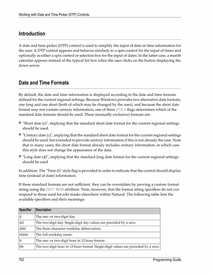
Introduction
A date and time picker (DTP) control is used to simplify the input of date or time information forthe user. A DTP control appears and behaves similarly to a spin control for the input of times andoptionally as either a spin control or selection box for the input of dates. In the latter case, a monthcalendar appears instead of the typical list box when the user clicks on the button displaying thedown arrow.
Date and Time Formats
By default, the date and time information is displayed according to the date and time formatsdefined for the current regional settings. BecauseWindows provides two alternative date formats,one long and one short (both of which may be changed by the user), and because the short dateformat may not contain century information, one of three STYLE flags determines which of thestandard date formats should be used. These (mutually exclusive) formats are:
■ "Short date (s)", implying that the standard short date format for the current regional settingsshould be used.
■ "Century date (c)", implying that the standard short date format for the current regional settingsshould be used, but extended to provide century information if this is not already the case. Notethat in many cases, the short date format already includes century information, in which casethis style does not change the appearance of the date.
■ "Long date (d)", implying that the standard long date format for the current regional settingsshould be used
In addition. The "Time (t)" style flag is provided in order to indicate that the control should displaytime (instead of date) information.
If these standard formats are not sufficient, they can be overridden by proving a custom formatstring using the EDIT-MASK attribute. Note, however, that the format string specifiers do not cor-respond to those used for edit masks elsewhere within Natural. The following table lists theavailable specifiers and their meanings:
DescriptionSpecifier
The one- or two-digit day.d
The two-digit day. Single-digit day values are preceded by a zero.dd
The three-character weekday abbreviation.ddd
The full weekday name.dddd
The one- or two-digit hour in 12-hour format.h
The two-digit hour in 12-hour format. Single-digit values are preceded by a zero.hh
Programming Guide702
Working with Date and Time Picker (DTP) Controls

DescriptionSpecifier
The one- or two-digit hour in 24-hour format.H
The two-digit hour in 24-hour format. Single-digit values are preceded by a zero.HH
The one- or two-digit minute.m
The two-digit minute. Single-digit values are preceded by a zero.mm
The one- or two-digit second.s
The two-digit second. Single-digit values are preceded by a zero.ss
The one- or two-digit month number.M
The two-digit month number. Single-digit values are preceded by a zero.MM
The three-character month abbreviation.MMM
The full month name.MMMM
The one-letter AM/PM abbreviation (that is, AM is displayed as A).t
The two-letter AM/PM abbreviation (that is, AM is displayed as AM).tt
The last two digits of the year (that is, 2005 would be displayed as 05).yy
The full year (that is, 2005 would be displayed as 2005).yyyy
In addition, any characters in quotes are displayed exactly as specified. To specify the quotecharacter itself within a quoted string, two consecutive single quote characters should be used.Spaces and punctuation marks (such as the comma) do not need to be quoted.
For example, in order to display the string "John's birthday is Friday, December 31, 1969", the DTPcontrol's EDIT-MASK attribute would be set to "John' 's birthday is' dddd, MMMM d, yyyy".
Inputting Dates and Times
The DTP control provides several ways of modifying the specified information:
■ By the user, by entering numerical information (day numbers, etc.) directly.■ By the user, by incrementing or decrementing the selected field (e.g. day number, month name)via the + or - keys, respectively.
■ By the user, if the DTP control has either the "Time (t)" or "Up-down (u)" style, by selecting therequired field and incrementing or decrementing the value via the up-down ("spin") control.
■ By the user, if the DTP control is using a month calendar, by pressing the down arrow to openthe month calendar and navigating to the required date. Unlike the above method, this methodupdates all date fields simultaneously.
■ Programmatically, by updating the TIME attribute with the required date or time.
For example, to set the date or time in a DTP control to the current date or time, use the followingassignments:
703Programming Guide
Working with Date and Time Picker (DTP) Controls

#DTP-1.TIME := *DATX
or
#DTP-1.TIME := *TIMX
respectively, where #DTP-1 is assumed to be the handle of the DTP control.
Note that the DTP control stores both date and time information, even though it only allowsediting of the date or time component, depending on the control's style.
If the DTP control's date or time is modified by the user, a CHANGE event is raised for the control(if not suppressed). This does not happen if the DTP control is modified programmatically.
Null Values
If the "Allow 'no value' (n)" style is specified for the DTP control, the control displays a check box.If this check box is unchecked, the interpretation is that there is no date or time associated withthe control. The application can test for this state by querying the control's CHECKED attribute. Itcan also revert the control to the "no value" state by setting the CHECKED attribute back to UNCHECKED.Note that it is, however, not possible to explicitly set the CHECKED attribute to CHECKED, as this isdone implicitlywhenever a date or time is applied to the control. Furthermore, the CHECKED attributemay not be set at all for DTP controls without the "Allow 'no value' (n)" style.
Calendar Colors and Font
The colors and font used by the month calendar (if any) associated with the DTP control may bechanged by use of the SET-AUX-COLOR and SET-AUX-FONT actions, respectively.
Programming Guide704
Working with Date and Time Picker (DTP) Controls

88 Working with Dialog Bar Controls
■ Introduction .................................................................................................................................. 706■ Creating a Dialog Bar Control ........................................................................................................... 706■ Types of Dialog Bar Control ............................................................................................................. 706■ UI Transparency ............................................................................................................................ 709■ Client-Size Event ........................................................................................................................... 709■ Close Button ................................................................................................................................. 710■ Sample Code ................................................................................................................................ 710
705

Introduction
A dialog bar is similar to a tool bar control in that it can either docked to one of the interior sidesof the dialog's frame or (optionally) floated in its own separate window. Unlike tool bar controls,however, dialog bar controls are conceived general-purpose container controls and are not dedicatedto containing primarily tool bar items. Furthermore, there are a number of other visual and beha-vioral differences between tool bar controls and dialog bars, some of which are discussed below.
A good example of a dialog bar control is the library workspace window in Natural Studio.
Creating a Dialog Bar Control
Dialog bar controls are created in the dialog editor in the same way as other standard controls(such as list boxes or push buttons) are. That is, they are either created statically in the dialog ed-itor via the Insertmenu or by drag and drop from the Insert tool bar, or dynamically at run-timeby using a PROCESS GUI ACTION ADD statement with the TYPE attribute set to DIALOGBAR.
Types of Dialog Bar Control
A dialog bar control can exist in one of the following three basic forms (in order of complexity):
1. Neither dockable nor sizeable.
2. Dockable, but not sizeable.
3. Dockable and sizeable.
The dialog bar control is dockable if its DRAGGABLE attribute is set. It is sizeable if the "Dynamic(Y)" STYLE flag is set.
The following example shows an example of a non-dockable, non-sizeable dialog bar. The editarea on the right fills the entire client area of the dialog. The dialog bar cannot be dragged by theuser and extends to fill the entire length of the side on which it is positioned:
Programming Guide706
Working with Dialog Bar Controls

Setting the “dockable” state in the Dialog Bar Attributeswindow in the dialog editor causes thewindow to be draggable by the user. Note also that the dialog bar no longer extends to occupythe full length of the side to which it is docked (another dialog bar control or tool bar control couldbe docked underneath it):
The user can drag the dialog bar control and re-dock it to another side of the owner dialog, or floatit in its own separate window, as shown below:
If the dialog bar control ismade sizeable (by checking the "Dynamic (Y)" style flag in theAttributeswindow), a longitudinal splitter bar appears, allowing the dialog bar control to be resized. Notethat sizeable dialog bar controls expand to fill the entire length of the side they are docked to thatis not occupied by non-sizeable bars:
707Programming Guide
Working with Dialog Bar Controls

If a gripper bar, zoom and close button are added (by setting the "Gripper (g)", "Zoom button (z)"and "Close button (x)" style flags in the Attributeswindow), the dialog bar control takes on thefamiliar appearance of the control used to display the library workspace in Natural Studio. Notethat the zoom button is disabled, because there is no other sizeable dialog bar control on the samerow:
If a second sizeable dialog bar control is added, and docked alongside the first on the same row,a transverse splitter bar appears allowing the relative sizes of the two dialog bar controls to bechanged. Note that the zoom button is now enabled:
Clicking on the zoom button toggles between the maximized and restored states of a sizeabledialog bar control. Maximizing a dialog bar control causes the other sizeable dialog bar controls
Programming Guide708
Working with Dialog Bar Controls

on the same row to be minimized, and the released space to be taken up by the maximized bar,as shown below:
Note that the direction of the arrow is displayed by the zoom button on the maximized bar haschanged direction in order to indicate that the next time this button is pressed, the bar will be re-stored, rather than maximized. When a bar is restored, all sizeable dialog bars on the row revertto their normalized sizes. These are usually the sizes prior to themaximize operation, unless therehas been a change in the visible bars on the row in themeantime (e.g., visible bar hidden or hiddenbar shown, new bar docked on row, etc.).
Note that if the length of a bar on a row is changed via a tranverse splitter bar, all visible bars onthe row are automatically restored.
UI Transparency
A dockable dialog bar control may normally be dragged via either its gripper bar (if any) or itsbackground. If the "UI transparent (T)" style is set, however, the bar may only be dragged via itsgripper bar (if any). If such a (sizeable) bar does not have a gripper bar, resizing of the control isonly possible via the splitter bar(s), whichmay be a desirable feature in some situations. Addition-ally, only allowing dragging via the gripper bar helps prevent unintentional initiation of dragoperations.
Client-Size Event
The dialog's client window is reduced in size to exclude the areas occupied by tool bar, status barand dialog bar controls. If a dockable window (tool bar or dialog bar control) is floated, re-dockedto another side of the owner window, or is shown or hidden, the size of the client window canchange, even though the exterior dimensions of the window have not altered. Because the SIZEevent is reserved for changes in a dialog's exterior size, applications which need to keep track ofthe size of the client window should instead use the CLIENT-SIZE event for this purpose. The ac-
709Programming Guide
Working with Dialog Bar Controls

tual size of the dialog client window can then be determined within this event by means of theINQ-INNER-RECT action.
Close Button
The close button (if present) hides a dialog bar control rather than closing it, as is also the case forthe close button on floated tool bar controls. It is up to the application to provide a method of re-showing the bar. The next section provides some code for doing this (amongst other things).
Sample Code
Below is a full listing of an external subroutine that can, in most cases, be used “as-is” in order toallow user control over the display of tool bars and dialog bars. The code is designed to bepowerful enough to cope withMDI applications, but also works with non-MDI (i.e., SDI) applica-tions.
The subroutine appends the tool and dialog bar captions (STRING attribute) to the dialog's contextmenu. If the dialog does not have a context menu, one is created and assigned to the dialog auto-matically. It assumes that, in anMDI application, there are some tool bars and dialog bars that areglobal (i.e., relevant for all types of MDI child dialogs) and some which are private (i.e., relevantonly for one type of MDI child dialog). For example, in Natural Studio, the Object tool bar is anexample of a global tool bar, whereas the dialog editor options tool bar is private to the dialogeditor. When the user switches between MDI child dialogs, the context menu is changed to onlyshow the global tool bars plus any private tool bars relevant to the currently active dialog. Further-more, the same private bars are displayed as the last time this dialog was displayed (if the Savelayout check box in the Dialog Attributeswindow is checked, the subset of bars shown is evenretained between sessions).
The subroutine should be called in the AFTER-ANY event handler of the main dialog (i.e., the MDIframe dialog for MDI applications), as follows (assuming the main dialog's handle variable nameis set to the default value of #DLG$WINDOW):
PERFORM PROCESS-BAR-COMMANDS #DLG$WINDOW
In addition, the following steps are optional:
1. The bars are listed in the contextmenu in the order inwhich they appear in the control sequence.Therefore, you may wish to re-sequence the tool and dialog bars (e.g., to ensure that the globaltool bars are displayed before the private ones in MDI applications).
2. The code does not insert a separator before the list of available bars on the context menu.Therefore, if you are already using a context menu for the dialog, you would probably want toensure that your context menu ends with a separator.
Programming Guide710
Working with Dialog Bar Controls

3. ForMDI applications, for each private bar, you should enter the name of the dialog (e.g. "CHILD"if the dialog's file name isCHILD.NS3) to which the tool bar “belongs” into theControl ID fieldof the Attributeswindow for the bar in the dialog editor. For each global bar, leave this fieldempty. If you wish the bar to be displayed only when no MDI child dialog is active, enter thename of the MDI frame dialog here.
4. For MDI applications, you should uncheck the Enabled check box in the Attributeswindowfor each bar that should not be displayed by default.
DEFINE DATAPARAMETER
1 #DIALOG HANDLE OF GUILOCAL
1 #CONTROL HANDLE OF GUI1 #ACTIVE-DLG HANDLE OF GUI1 #CTXMENU HANDLE OF CONTEXTMENU1 #MITEM-DYN HANDLE OF MENUITEM
LOCAL USING NGULKEY1END-DEFINE*DEFINE SUBROUTINE PROCESS-BAR-COMMANDS
DECIDE ON FIRST *EVENTVALUE 'COMMAND-STATUS'
PERFORM COMMAND-STATUSVALUE 'IDLE'
PERFORM IDLEVALUE 'CLICK'PERFORM CLICK
VALUE 'BEFORE-OPEN'PERFORM BEFORE-OPEN
VALUE 'AFTER-OPEN'PERFORM AFTER-OPEN
NONEIGNORE
END-DECIDE*
DEFINE SUBROUTINE COMMAND-STATUS/* Must enable our commands, otherwise they're automatically disabled!#CTXMENU := #DIALOG.CONTEXT-MENU#MITEM-DYN := #CTXMENU.FIRST-CHILDREPEAT WHILE #MITEM-DYN <> NULL-HANDLE
IF #MITEM-DYN.CLIENT-HANDLE <> NULL-HANDLE#MITEM-DYN.ENABLED := TRUE
END-IF#MITEM-DYN := #MITEM-DYN.SUCCESSOR
END-REPEATEND-SUBROUTINE
*DEFINE SUBROUTINE IDLE
PERFORM SWITCH-BARS
711Programming Guide
Working with Dialog Bar Controls
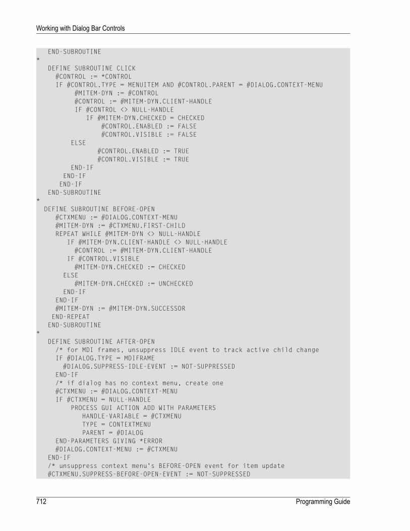
END-SUBROUTINE*
DEFINE SUBROUTINE CLICK#CONTROL := *CONTROLIF #CONTROL.TYPE = MENUITEM AND #CONTROL.PARENT = #DIALOG.CONTEXT-MENU
#MITEM-DYN := #CONTROL#CONTROL := #MITEM-DYN.CLIENT-HANDLEIF #CONTROL <> NULL-HANDLE
IF #MITEM-DYN.CHECKED = CHECKED#CONTROL.ENABLED := FALSE#CONTROL.VISIBLE := FALSE
ELSE#CONTROL.ENABLED := TRUE#CONTROL.VISIBLE := TRUE
END-IFEND-IF
END-IFEND-SUBROUTINE
*DEFINE SUBROUTINE BEFORE-OPEN
#CTXMENU := #DIALOG.CONTEXT-MENU#MITEM-DYN := #CTXMENU.FIRST-CHILDREPEAT WHILE #MITEM-DYN <> NULL-HANDLE
IF #MITEM-DYN.CLIENT-HANDLE <> NULL-HANDLE#CONTROL := #MITEM-DYN.CLIENT-HANDLE
IF #CONTROL.VISIBLE#MITEM-DYN.CHECKED := CHECKED
ELSE#MITEM-DYN.CHECKED := UNCHECKED
END-IFEND-IF#MITEM-DYN := #MITEM-DYN.SUCCESSOREND-REPEAT
END-SUBROUTINE*
DEFINE SUBROUTINE AFTER-OPEN/* for MDI frames, unsuppress IDLE event to track active child changeIF #DIALOG.TYPE = MDIFRAME
#DIALOG.SUPPRESS-IDLE-EVENT := NOT-SUPPRESSEDEND-IF/* if dialog has no context menu, create one#CTXMENU := #DIALOG.CONTEXT-MENUIF #CTXMENU = NULL-HANDLE
PROCESS GUI ACTION ADD WITH PARAMETERSHANDLE-VARIABLE = #CTXMENUTYPE = CONTEXTMENUPARENT = #DIALOG
END-PARAMETERS GIVING *ERROR#DIALOG.CONTEXT-MENU := #CTXMENU
END-IF/* unsuppress context menu's BEFORE-OPEN event for item update#CTXMENU.SUPPRESS-BEFORE-OPEN-EVENT := NOT-SUPPRESSED
Programming Guide712
Working with Dialog Bar Controls

/* display bars according to contextPERFORM SWITCH-BARSEND-SUBROUTINE
*DEFINE SUBROUTINE SWITCH-BARS
IF #DIALOG.TYPE = MDIFRAME#ACTIVE-DLG := #DIALOG.ACTIVE-CHILD
END-IFIF #ACTIVE-DLG = NULL-HANDLE#ACTIVE-DLG := #DIALOG
END-IFIF #ACTIVE-DLG <> #DIALOG.CLIENT-HANDLE#CTXMENU := #DIALOG.CONTEXT-MENUIF #CTXMENU <> NULL-HANDLE
/* Remove any dynamic menu items previously created#CONTROL := #CTXMENU.FIRST-CHILDREPEAT WHILE #CONTROL <> NULL-HANDLE#MITEM-DYN := #CONTROL.SUCCESSORIF #CONTROL.CLIENT-HANDLE <> NULL-HANDLE
PROCESS GUI ACTION DELETE WITH #CONTROLEND-IF#CONTROL := #MITEM-DYN
END-REPEAT/* Search for all tool bar and dialog bar controls#CONTROL := #DIALOG.FOLLOWSREPEAT WHILE #CONTROL <> #DIALOG
IF #CONTROL.TYPE = TOOLBARCTRL OR#CONTROL.TYPE = DIALOGBAR
#CONTROL.CLIENT-KEY := 'CONTROL-ID'IF #CONTROL.CLIENT-VALUE = ' ' OR
#CONTROL.CLIENT-VALUE = #ACTIVE-DLG.NAME#CONTROL.VISIBLE := #CONTROL.ENABLED/* Create menu entry for barPROCESS GUI ACTION ADD WITH PARAMETERSHANDLE-VARIABLE = #MITEM-DYNTYPE = MENUITEMPARENT = #CTXMENUSTRING = #CONTROL.STRINGSUCCESSOR = #MITEM-DYNCLIENT-HANDLE = #CONTROL
END-PARAMETERS GIVING *ERRORELSE#CONTROL.VISIBLE := FALSE
END-IFEND-IF#CONTROL := #CONTROL.FOLLOWS
END-REPEATEND-IF/* Save handle of currently active dialog#DIALOG.CLIENT-HANDLE := #ACTIVE-DLG
END-IFEND-SUBROUTINE
713Programming Guide
Working with Dialog Bar Controls

END-SUBROUTINEEND
Programming Guide714
Working with Dialog Bar Controls

89 Working with Error Events
When a runtime error occurs while a dialog is active, the dialog receives an error event. You canspecify event-handler code to be executed whenever this error occurs. If no error event-handlercode is specified, Natural aborts with an error message and all dialogs will be closed.
You can continue normal dialog processing after error handling by specifying an ESCAPE ROUTINEstatement at the end of the event-handler code.
The dialog editor generates an ON ERROR statement for the event handler. If, for example, youwantto prevent the end user from closing the entire application when trying to divide an integer byzero, and the parameter ZD is set to ON, the error event-handler code might look like this:
COMPRESS 'Natural error' *ERROR 'occurred.' INTO #DLG$WINDOW.STATUS-TEXTESCAPE ROUTINE
715

716

90 Working with a Group of Radio Button Controls
Radio button controls are created just like push button controls or toggle button controls; however,they are grouped using the GROUP-ID attribute. If you define a number of radio button controls asa group, only one button is selected at any time. The GROUP-ID attribute provides this selectionlogic.
You group several radio button controls by assigning them the same GROUP-ID value (groupnumber) in their attributeswindows. If the end user clicks on a radio button control, all other radio-button controls in the dialog with the same GROUP-IDwill be deselected. They will also bedeselected if one radio button control is selected by code like the following:
...1 #RB-1 HANDLE OF RADIOBUTTON
...#RB-1.CHECKED := CHECKED /* Set the CHECKED attribute to value CHECKED...
You also have to bear in mind that the end user should be able to use the keyboard for navigationinside a group of radio button controls: TAB selects the first radio button control, and the arrowkeys enable you to navigate within the radio button group. To ensure that Natural automaticallyallows for such navigation, the radio button controls must follow each other directly in the navig-ation sequence. If you are dynamically adding a radio button control via the PROCESS GUI statementaction ADD, this can be achieved by specifying a value for the button's FOLLOWS attribute.
To edit the navigation sequence
■ From the Dialogmenu, choose Control Sequence.
717

718
91 Working with Image List Controls
■ Introduction .................................................................................................................................. 720■ Creating the Image List Control ........................................................................................................ 720■ Adding Images .............................................................................................................................. 720■ Composite Images ......................................................................................................................... 721■ Scaling and Transparency ............................................................................................................... 721■ Bitmaps vs. Icons .......................................................................................................................... 722■ Using an Image List ....................................................................................................................... 723■ Referencing Images from the Image List ............................................................................................ 723■ Overlay Images ............................................................................................................................. 724■ Modifying Images .......................................................................................................................... 725■ Deleting Images ............................................................................................................................ 726■ Deleting the Image List Control ......................................................................................................... 726
719

Introduction
An image list control is a container of ordered images that can be associatedwith particular controltypes, such as list view and tree view controls. It allows images to be efficiently re-used by thecontrol's items without the image being re-loaded from the disk each time. It also ensures that allimages are compatible (e.g., are of the same size and color organization).
Creating the Image List Control
Image list controls are created, as usual, via the ADD action:
PROCESS GUI ACTION ADD WITHPARAMETERS
HANDLE-VARIABLE = #IMGLST-1TYPE = IMAGELISTPARENT = #DLG$WINDOWSTYLE = 'LS'
END-PARAMETERS GIVING *ERROR
An image list control may consist of up to two sets of images internally, one consisting of largeimages (typically 32 by 32 pixels) and one consisting of small images (typically 16 by 16 pixels).Which of these (if any) is created internally depends on the image list control's "Large Images (L)"and "Small Images (S)" STYLE flags. If neither of these flags are specified, a single set of images iscreated, with an explicit image size as determined by the image list control's ITEM-W and ITEM-Hattribute values. If both of these are zero, small images are assumed.
Adding Images
Images are added to an image list by creating an image control, based on the required image(bitmap or icon) file, as a child of the image list control:
PROCESS GUI ACTION ADD WITHPARAMETERS
HANDLE-VARIABLE = #IMG-1TYPE = IMAGEPARENT = #IMGLST-1BITMAP-FILE-NAME = 'example.bmp'
END-PARAMETERS GIVING *ERROR
Programming Guide720
Working with Image List Controls

Images are appended to the list by default, unless the SUCCESSOR attribute is used to insert themat a specific position.
Composite Images
Image controls can be categorized into two types: single-image image controls and multi-imageimage controls.
Single-image image controls contribute a single image to each set of images stored by the parentimage list control. That is, if the image list contains both large and small images, one of each isprovided by the image control. Single-image image controls may be bitmaps or icons.
Multi-image image controls, as the name suggests, may contribute more than one image (in eachrequired size) to the parent image list control.Multi-image image controlsmust be based on bitmapfiles, rather than icons, and are distinguishable from single-image image controls in that their"Composite image (C)" STYLE flag is set:
PROCESS GUI ACTION ADD WITHPARAMETERS
HANDLE-VARIABLE = #IMG-1TYPE = IMAGEPARENT = #IMGLST-1STYLE = 'CsT'BITMAP-FILE-NAME = 'composite.bmp'
END-PARAMETERS GIVING *ERROR
The number of images in the composite bitmap is automatically calculated from the size of thebitmap and the width and height of the images in the (smallest) set of images stored by the parentimage list control. Thus, in the case where both large and small images are stored, the bitmapwould typically be 16 pixels high, and (16 * N) pixels wide, where N is the number of images tobe stored in the image control. Here is an example of a composite bitmap containing five images:
Scaling and Transparency
In the example provided in the preceding section, two other style flags were specified in additionto the "Composite image (C)" style: namely, the "Scaled (s)" and the "Transparent (T)" style flags.The first of these is absolutely necessary if the parent image list control contains multiple sets ofimages in different sizes. For example, if large images are also being used, the flag causes thecomposite image to be scaled internally first before being chopped up into its constituent images,as follows:
721Programming Guide
Working with Image List Controls

Note that if the "Scaled (s)" style flag were not specified, the composite bitmapwould be extendedin the background color, rather than being scaled, before being chopped up, as shown below:
This would result in the following five large images:
Needless to say, this is not normally what you want!
The "Transparent (T)" style flag indicates that the images should be rendered transparently, suchthat all pixels in the bitmap's background color are not drawn. The background color can be expli-citly specified by setting the BACKGROUND-COLOUR-VALUE and/or BACKGROUND-COLOUR-NAME attributesfor the image control to the required value. Otherwise, if no color is specified (as in the previousexample), the color of the first (i.e., top-left) pixel in the bitmap is taken as being the backgroundcolor.
Of course, both the "Scaled (s)" and the "Transparent (T)" style flags can also be applied to non-composite images.
Bitmaps vs. Icons
Apart fromnot being able to sourcemulitple images (as described above), icons differ frombitmapsin two important ways. Firstly, a single icon (.ICO) file can contain multiple versions of the iconsin different sizes. Thus when Natural requires the large image, and the source is an icon file, thelarge icon defined in the icon file is used, if present, in preference to synthesizing it from one ofthe other icons in the file by scaling. Similarly, when Natural requires the small image, and thesource is an icon file, the small icon defined in the icon file is used, if present. In contrast, bitmapfiles do not contain multiple images, so if both large and small images are required for an imagelist, one of the two images (usually the large image)must by synthesized from the other as describedin the previous section.
Secondly, icons typically contain amonochromebitmap (known as the imagemask) that determineswhich pixels in the image are transparent (i.e., should not be drawn). Thus, when Natural loadsan image from an icon file, and the image control's BACKGROUND-COLOUR-NAME attribute is set toDEFAULT (or is not specified), and the image control's "Transparent (T)" style flag is specifiedwithoutthe "Scaled (s)" style flag, Natural uses the icon's transparencymask, instead of making the above-mentioned assumption that all pixels in the same color as the first pixel are to be rendered trans-parently, as is the case for images loaded from a bitmap file. If an explicit (i.e., non-default) back-
Programming Guide722
Working with Image List Controls
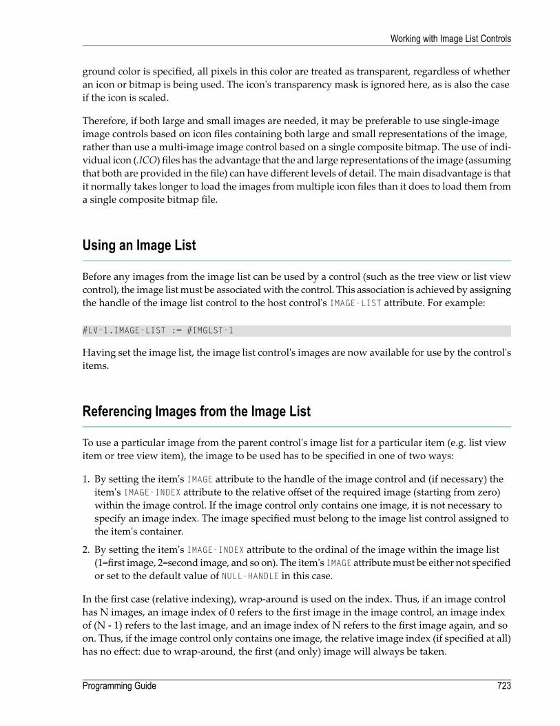
ground color is specified, all pixels in this color are treated as transparent, regardless of whetheran icon or bitmap is being used. The icon's transparency mask is ignored here, as is also the caseif the icon is scaled.
Therefore, if both large and small images are needed, it may be preferable to use single-imageimage controls based on icon files containing both large and small representations of the image,rather than use a multi-image image control based on a single composite bitmap. The use of indi-vidual icon (.ICO) files has the advantage that the and large representations of the image (assumingthat both are provided in the file) can have different levels of detail. Themain disadvantage is thatit normally takes longer to load the images frommultiple icon files than it does to load them froma single composite bitmap file.
Using an Image List
Before any images from the image list can be used by a control (such as the tree view or list viewcontrol), the image listmust be associatedwith the control. This association is achieved by assigningthe handle of the image list control to the host control's IMAGE-LIST attribute. For example:
#LV-1.IMAGE-LIST := #IMGLST-1
Having set the image list, the image list control's images are now available for use by the control'sitems.
Referencing Images from the Image List
To use a particular image from the parent control's image list for a particular item (e.g. list viewitem or tree view item), the image to be used has to be specified in one of two ways:
1. By setting the item's IMAGE attribute to the handle of the image control and (if necessary) theitem's IMAGE-INDEX attribute to the relative offset of the required image (starting from zero)within the image control. If the image control only contains one image, it is not necessary tospecify an image index. The image specified must belong to the image list control assigned tothe item's container.
2. By setting the item's IMAGE-INDEX attribute to the ordinal of the image within the image list(1=first image, 2=second image, and so on). The item's IMAGE attributemust be either not specifiedor set to the default value of NULL-HANDLE in this case.
In the first case (relative indexing), wrap-around is used on the index. Thus, if an image controlhas N images, an image index of 0 refers to the first image in the image control, an image indexof (N - 1) refers to the last image, and an image index of N refers to the first image again, and soon. Thus, if the image control only contains one image, the relative image index (if specified at all)has no effect: due to wrap-around, the first (and only) image will always be taken.
723Programming Guide
Working with Image List Controls

In the second case (absolute indexing), no wrap-around is used on the image index, which mustbe in the range 1 through to the number of images in the image list (inclusive). If the specifiedvalue is not in this range, no image is displayed for the specified item.
Note that the IMAGE-INDEX attribute can also be applied to an image control. In this case, the attributeis read-only, and returns the offset (starting from zero) of the image control's first image withinthe parent image list control.
One advantage of using relative indexing is that Natural keeps track the references to the specifiedimage (both in the dialog editor and at run-time) and automatically propagates changes to theimage control or to its position in the image list. In practice, absolute indexing is probably mostuseful in situations where an image list control with a single composite (i.e., multi-image) imagecontrol is used, and where the images are not modified at run-time.
Overlay Images
There are situations where it is desirable to be able to offer several variations of an image. For ex-ample, the displayed image for an item representing a foldermay need to bemodified to indicatedthat the folder is active. Rather than providing an image of a folder and an image of an activefolder, it may be more convenient to provide only the first of these images, and to indicate theactive state via a second image containing only the “active” symbol, which is then superimposedon the first. Such an image is referred to as an overlay image, to distinguish it from the underlyingbase image.
Overlay images are contained within the same image list that is used to display the base images,as determined via the host control's IMAGE-LIST attribute. They are therefore the same size as thebase images, but are always rendered transparently, to allow the underlying image to showthrough.
To use an overlay image for an item, a value must be specified for the item's OVERLAY and/orOVERLAY-INDEX attributes. These attributes are used analogously to the IMAGE and IMAGE-INDEXattributes (respectively) for base images (see above).
For technical reasons, images intended for use as overlay images must be “pre-registered”. InNatural, this is done by setting the image list control's "O" (Overlay) STYLE. However, if the overlaycontrols are defined statically, this style is automatically set by the dialog editor. The presence orabsence of this style distinguishes base images from overlay images. Consequently, the OVERLAYattribute (if specified) can only refer to an image control with this style, whereas the IMAGE attribute(if specified) can only refer to an image control without it. If absolute indexing (see above) is beingused, the IMAGE-INDEX can refer to an overlay image (which is then “misused” as a base image).However, a corresponding attempt to use the OVERLAY-INDEX attribute to refer to a base imagefails (no overlay image is drawn).
Programming Guide724
Working with Image List Controls

Windows sets a limit on the number of overlay images that may be defined for an image list. Thislimit is currently 15. Note that if any composite overlay image controls are used, each sub-imagein the composite bitmap counts separately towards this quota.
As an example, suppose we create an image control based on a composite image containing theindividual overlay images, as follows:
PROCESS GUI ACTION ADD WITHPARAMETERS
HANDLE-VARIABLE = #IMG-2TYPE = IMAGEPARENT = #IMGLST-1STYLE = 'COs'BITMAP-FILE-NAME = 'overlays.bmp'
END-PARAMETERS GIVING *ERROR
Then, we could create a list view item (say) using the second overlay image from the compositebitmap by executing the following code:
PROCESS GUI ACTION ADD WITHPARAMETERS
TYPE = LISTVIEWITEMPARENT = #LV-1STRING = 'Item with overlay'IMAGE = #IMG-1IMAGE-INDEX = 3OVERLAY = #IMG-2OVERLAY-INDEX = 1
END-PARAMETERS GIVING *ERROR
In the above example, the list view item will use the fourth image from COMPOSITE.BMP as itsbase image, and the second image from OVERLAYS.BMP as the overlay image (relative imageindexes are, as alreadymentioned, zero-based). Note that the list view item is created anonymously(i.e., no explicit HANDLE-VARIABLE attribute value specified).
Modifying Images
Image controls may be modified even if they are currently in use. For example:
725Programming Guide
Working with Image List Controls

#IMG-1.BITMAP-FILE-NAME := 'new.bmp'
Natural keeps track of, and automatically updates and redraws, each item that explicitly (i.e., viarelative indexing) references an image from the modified image control. However, if absolute in-dexing is used, the corresponding items are not updated, even if they are implicitly referring toan image within the modified image control.
Deleting Images
Imagesmay be removed from the image list by deleting the complete image control via the DELETEaction. For example:
PROCESS GUI ACTION DELETE WITH #IMG-1 GIVING *ERROR
All items that explicitly (i.e., via relative indexing) reference an image from the deleted imagecontrol are automatically updated and redrawn to show no image.
However, if absolute indexing is being used, no automatic updating occurs. For example, supposean image list control contains three single-image image controls and that items exists that refer toall three images via absolute indexing. If the second image control is deleted, the items that usedto refer to the second image would suddenly reference the third image and the items that used torefer to the third image would “fall off the end” and not reference anything. Furthermore, thecontrols containing the items would not automatically be redrawn to reflect the changes.
It is, of course, also possible to delete all images in the image list in one go, via the DELETE-CHILDRENaction:
PROCESS GUI ACTION DELETE-CHILDREN WITH #IMGLST-1 GIVING *ERROR
This is equivalent to deleting each image in the image list individually.
Note that it is not possible to delete individual imageswithin a composite (i.e., multi-image) imagecontrol.
Deleting the Image List Control
An image list control may be deleted when no longer required, even if it is in use. For example:
Programming Guide726
Working with Image List Controls

PROCESS GUI ACTION DELETE WITH #IMGLST-1 GIVING *ERROR
All controls using the image list control are updated accordingly, and their IMAGE-LIST attributeis automatically reset to NULL-HANDLE.
727Programming Guide
Working with Image List Controls

728

92 Working with List Box Controls and Selection Box
Controls
List box controls and selection box controls contain a number of items. Both the controls and theitems are dialog elements; the controls are the parents of the items.
There are two ways of creating list box items and selection box items:
■ Use Natural code to create individual and multiple list box items dynamically; or■ use the dialog editor (to add single or arrays of list box items and selection box items).
In Natural code, this may look like this:
#AMOUNT := 5ITEM (1) := 'BERLIN'ITEM (2) := 'PARIS'ITEM (3) := 'LONDON'ITEM (4) := 'MILAN'ITEM (5) := 'MADRID'PROCESS GUI ACTION ADD-ITEMS WITH #LB-1 #AMOUNT #ITEM (1:5) GIVING #RESPONSE
You first specify the number of items you want to create, name the items, and use the PROCESSGUI statement action ADD-ITEMS.
If you want to go through all items of a list box control to find out which ones are selected, it isadvisable to use the SELECTED-SUCCESSOR attribute because if a list box control contains a largenumber of items (100, for example), this helps improve performance. If you use SELECTED-SUC-CESSOR, you have one query instead of 100 individual queries if you use the attributes SELECTEDand SUCCESSOR.
Example:
729

/* Displays the STRING attribute of every SELECTED list-box itemMOVE #LISTBOX.SELECTED-SUCCESSOR TO #LBITEMREPEAT UNTIL #LBITEM = NULL-HANDLE
.../* STRING display logic
MOVE #LBITEM.SELECTED-SUCCESSOR TO #LBITEMEND-REPEAT
For performance reasons, you should not use the SELECTED-SUCCESSOR attribute to refer to thesame dialog element handle twice, because Natural goes through the list of item handles twice:
/* Displays the STRING attribute of every SELECTED list-box item,/* but may be slowMOVE #LISTBOX.SELECTED-SUCCESSOR TO #LBITEMREPEAT UNTIL #LBITEM = NULL-HANDLE
IF #LBITEM.SELECTED-SUCCESSOR = NULL-HANDLE /* Searches in the list of itemsIGNORE
END-IF.../* STRING display logicMOVE #LBITEM.SELECTED-SUCCESSOR TO #LBITEM /* Searches in the list of items
END-REPEAT /* for the second time
To avoid this problem, you use a second variable #OLDITEM besides #LBITEM:
/* Displays the STRING attribute of every SELECTED list-box itemMOVE #LISTBOX.SELECTED-SUCCESSOR TO #LBITEMREPEAT UNTIL #LBITEM = NULL-HANDLE
#OLDITEM = #LBITEM#LBITEM = #LBITEM.SELECTED-SUCCESSOR/* Searches in the list of items (once)IF #LBITEM = NULL-HANDLE
IGNOREEND-IF.../* Display logic using #OLDITEM.STRING
END-REPEAT
If you retrieve the handle values of the selected items, a value other than NULL-HANDLEwouldnormally be returned by selected items. Such a handle value can also be returned by non-selecteditems if you assign SELECTED-SUCCESSOR a value immediately before retrieving the SELECTED-SUCCESSOR value of a non-selected item, as shown in the following example:
Programming Guide730
Working with List Box Controls and Selection Box Controls

...PTR := #LB-1.SELECTED-SUCCESSORPTR := NOT_SELECTEDHANDLE.SELECTED-SUCCESSORIF NOT_SELECTEDHANDLE.SELECTED-SUCCESSOR = NULL-HANDLE THEN
#DLG$WINDOW.STATUS-TEXT := 'NULL-HANDLE'ELSE
COMPRESS 'NEXT SELECTION: ' PTR.STRING TO #DLG$WINDOW.STATUS-TEXTEND-IF...
If you want to query whether a particular item in a list box control is selected, you get the bestperformance by using the SELECTED attribute:
#DLG$WINDOW.STRING:= #LB-1-ITEMS.SELECTED(3)
Protecting Selection Box Controls and Input Field Controls
To prevent an end user from typing in input data in a selection box control or input field control,you have several possiblities, for example:
■ setting the MODIFIABLE attribute to FALSE for the dialog element, or■ setting session parameter AD=P, or■ using a control variable (CV).
If a selection box control is protected, it is still possible to select items; only values from the itemlist will be displayed in its input field. If the STRING attribute is set to a value (dynamically or byinitialisation) which is not in the item list, the value will not be visible to the end user.
731Programming Guide
Working with List Box Controls and Selection Box Controls

732

93 Working with List View Controls
■ Introduction .................................................................................................................................. 734■ View Modes .................................................................................................................................. 734■ Setting Item Images ....................................................................................................................... 736■ Item Placement ............................................................................................................................. 736■ Item Selection ............................................................................................................................... 738■ Item Activation .............................................................................................................................. 739■ List View Columns and Sub-items ..................................................................................................... 740■ Sorting ........................................................................................................................................ 743■ Label Editing ................................................................................................................................. 745■ Multiple Context Menus .................................................................................................................. 747■ Drag and Drop .............................................................................................................................. 748
733

Introduction
A list view control can be used to display data in icon or column-based form. It is a very powerfulcontrol. Nevertheless, if you wish to display your data in tabular form and support direct in-placeediting of any column value, you should consider using the table control instead.
View Modes
List view controls in Natural can display their data in one of four view modes: icon, small icon,list or report.
In icon view mode, the data is displayed in large icon form:
In small icon view mode, the item labels are displayed alongside the icons. As for the icon view,the items can optionally be displayed in arbitrary positions:
In list view mode, the items are displayed similarly to the small icon view, but cannot be freelypositioned. Instead, they are displayed in columns:
Programming Guide734
Working with List View Controls
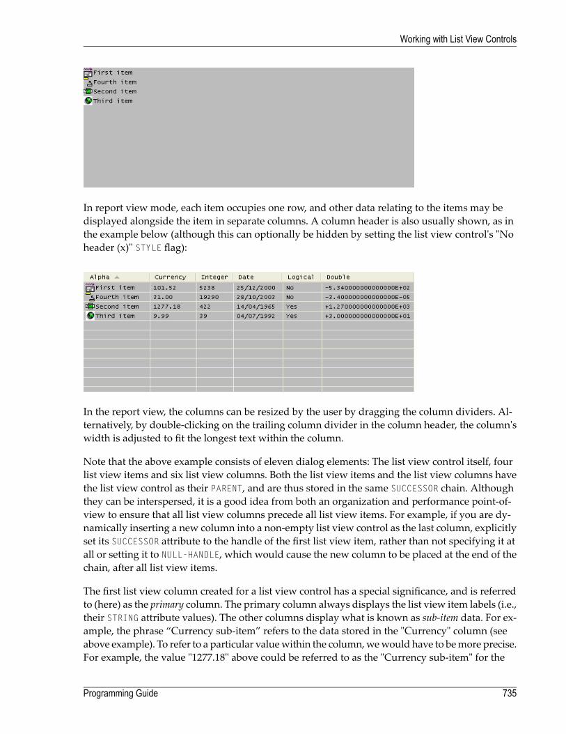
In report view mode, each item occupies one row, and other data relating to the items may bedisplayed alongside the item in separate columns. A column header is also usually shown, as inthe example below (although this can optionally be hidden by setting the list view control's "Noheader (x)" STYLE flag):
In the report view, the columns can be resized by the user by dragging the column dividers. Al-ternatively, by double-clicking on the trailing column divider in the column header, the column'swidth is adjusted to fit the longest text within the column.
Note that the above example consists of eleven dialog elements: The list view control itself, fourlist view items and six list view columns. Both the list view items and the list view columns havethe list view control as their PARENT, and are thus stored in the same SUCCESSOR chain. Althoughthey can be interspersed, it is a good idea from both an organization and performance point-of-view to ensure that all list view columns precede all list view items. For example, if you are dy-namically inserting a new column into a non-empty list view control as the last column, explicitlyset its SUCCESSOR attribute to the handle of the first list view item, rather than not specifying it atall or setting it to NULL-HANDLE, which would cause the new column to be placed at the end of thechain, after all list view items.
The first list view column created for a list view control has a special significance, and is referredto (here) as the primary column. The primary column always displays the list view item labels (i.e.,their STRING attribute values). The other columns display what is known as sub-item data. For ex-ample, the phrase “Currency sub-item” refers to the data stored in the "Currency" column (seeabove example). To refer to a particular valuewithin the column,wewould have to bemore precise.For example, the value "1277.18" above could be referred to as the "Currency sub-item" for the
735Programming Guide
Working with List View Controls
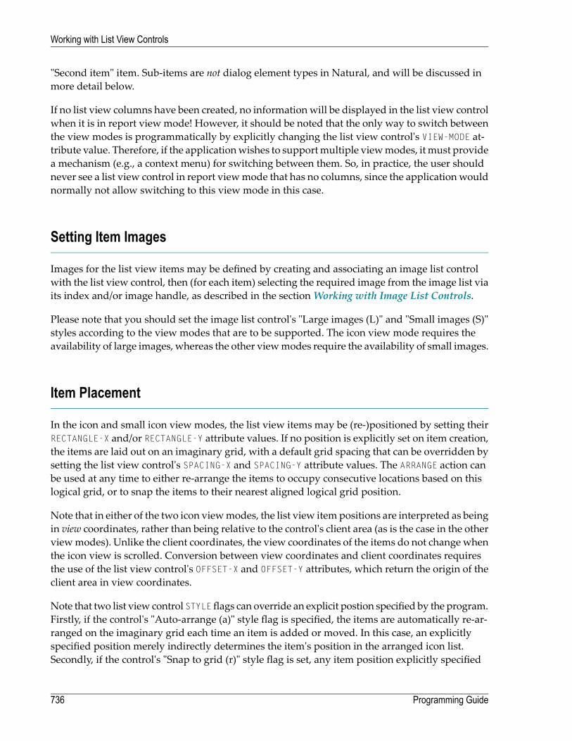
"Second item" item. Sub-items are not dialog element types in Natural, and will be discussed inmore detail below.
If no list view columns have been created, no informationwill be displayed in the list view controlwhen it is in report view mode! However, it should be noted that the only way to switch betweenthe view modes is programmatically by explicitly changing the list view control's VIEW-MODE at-tribute value. Therefore, if the applicationwishes to supportmultiple viewmodes, itmust providea mechanism (e.g., a context menu) for switching between them. So, in practice, the user shouldnever see a list view control in report viewmode that has no columns, since the applicationwouldnormally not allow switching to this view mode in this case.
Setting Item Images
Images for the list view items may be defined by creating and associating an image list controlwith the list view control, then (for each item) selecting the required image from the image list viaits index and/or image handle, as described in the sectionWorking with Image List Controls.
Please note that you should set the image list control's "Large images (L)" and "Small images (S)"styles according to the view modes that are to be supported. The icon view mode requires theavailability of large images, whereas the other viewmodes require the availability of small images.
Item Placement
In the icon and small icon view modes, the list view items may be (re-)positioned by setting theirRECTANGLE-X and/or RECTANGLE-Y attribute values. If no position is explicitly set on item creation,the items are laid out on an imaginary grid, with a default grid spacing that can be overridden bysetting the list view control's SPACING-X and SPACING-Y attribute values. The ARRANGE action canbe used at any time to either re-arrange the items to occupy consecutive locations based on thislogical grid, or to snap the items to their nearest aligned logical grid position.
Note that in either of the two icon viewmodes, the list view item positions are interpreted as beingin view coordinates, rather than being relative to the control's client area (as is the case in the otherviewmodes). Unlike the client coordinates, the view coordinates of the items do not change whenthe icon view is scrolled. Conversion between view coordinates and client coordinates requiresthe use of the list view control's OFFSET-X and OFFSET-Y attributes, which return the origin of theclient area in view coordinates.
Note that two list view control STYLEflags can override an explicit postion specified by the program.Firstly, if the control's "Auto-arrange (a)" style flag is specified, the items are automatically re-ar-ranged on the imaginary grid each time an item is added or moved. In this case, an explicitlyspecified position merely indirectly determines the item's position in the arranged icon list.Secondly, if the control's "Snap to grid (r)" style flag is set, any item position explicitly specified
Programming Guide736
Working with List View Controls

by the program will be adjusted to the nearest aligned position on the imaginary grid. Note thatthis style is superfluous if the "auto-arrange" style is set.
Since users are often familiar with being able tomodify list view item positions via drag and drop,it may be expected that the control automatically provides this capability. However, this is notthe case. If the application wishes to support drag and drop, it must explicitly cater for it, as de-scribed in the next section.
In the list view mode, the items are always displayed in columns (as already mentioned above)and are not re-positionable. However, the spacing between adjacent columns may be set via theSPACING attribute.
Note that the list view control does not remember item positions when switching between viewmodes. For example, if you switch away from one of the icon view modes and then back to itagain, the icons are always arranged. This behavior can be circumvented by providing explicitprogram code for saving and restoring item positions, as shown in the following example:
DEFINE SUBROUTINE SAVE-ITEM-POSITIONS#ITEM := #CONTROL.FIRST-CHILDREPEAT WHILE #ITEM <> NULL-HANDLE
IF #ITEM.TYPE = LISTVIEWITEM#ITEM.CLIENT-KEY := 'RECTANGLE-X'#ITEM.CLIENT-VALUE := #ITEM.RECTANGLE-X#ITEM.CLIENT-KEY := 'RECTANGLE-Y'#ITEM.CLIENT-VALUE := #ITEM.RECTANGLE-Y
END-IF#ITEM := #ITEM.SUCCESSOR
END-REPEATEND-SUBROUTINE*DEFINE SUBROUTINE RESTORE-ITEM-POSITIONS
#ITEM := #CONTROL.FIRST-CHILDREPEAT WHILE #ITEM <> NULL-HANDLE
IF #ITEM.TYPE = LISTVIEWITEM#ITEM.CLIENT-KEY := 'RECTANGLE-X'IF #ITEM.CLIENT-VALUE <> ' '#ITEM.RECTANGLE-X := VAL(#ITEM.CLIENT-VALUE)END-IF#ITEM.CLIENT-KEY := 'RECTANGLE-Y'IF #ITEM.CLIENT-VALUE <> ' '
#ITEM.RECTANGLE-Y := VAL(#ITEM.CLIENT-VALUE)END-IF
END-IF#ITEM := #ITEM.SUCCESSOR
END-REPEATEND-SUBROUTINE*DEFINE SUBROUTINE SWITCH-VIEW-MODE
IF #VIEW-MODE <> #CONTROL.VIEW-MODE
737Programming Guide
Working with List View Controls
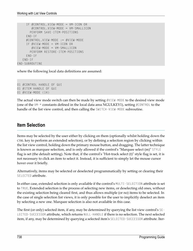
IF #CONTROL.VIEW-MODE = VM-ICON OR#CONTROL.VIEW-MODE = VM-SMALLICONPERFORM SAVE-ITEM-POSITIONS
END-IF#CONTROL.VIEW-MODE := #VIEW-MODEIF #VIEW-MODE = VM-ICON OR
#VIEW-MODE = VM-SMALLICONPERFORM RESTORE-ITEM-POSITIONS
END-IFEND-IF
END-SUBROUTINE
where the following local data definitions are assumed:
01 #CONTROL HANDLE OF GUI01 #ITEM HANDLE OF GUI01 #VIEW-MODE (I4)
The actual view mode switch can then be made by setting #VIEW-MODE to the desired view mode(one of the VM-* constants defined in the local data area NGULKEY1), setting #CONTROL to thehandle of the list view control, and then calling the SWITCH-VIEW-MODE subroutine.
Item Selection
Items may be selected by the user either by clicking on them (optionally whilst holding down theCTRL key to perform an extended selection), or by defining a selection region by clicking withinthe list view control, holding down the primarymouse button, and dragging. The latter techniqueis known as marquee selection, and is only allowed if the control's "Marquee select (m)" STYLEflag is set (the default setting). Note that, if the control's "Hot-track select (t)" style flag is set, it isnot necessary to click an item to select it. Instead, it is sufficient to simply let the mouse cursorhover over it briefly.
Alternatively, items may be selected or deselected programmatically by setting or clearing theirSELECTED attribute.
In either case, extended selection is only available if the control's MULTI-SELECTION attribute is setto TRUE. Extended selection is the process of selecting new items, or deselecting old ones, withoutthe existing selection being cleared first, and thus allows multiple (or no) items to be selected. Inthe case of single selection list views, it is only possible for the user to implicitly deselect an itemby selecting a new one. Marquee selection is also not available in this case.
The first (or only) selected item, if any, may be determined by querying the list view control's SE-LECTED-SUCCESSOR attribute, which returns NULL-HANDLE if there is no selection. The next selecteditem, if any, may be determined by querying a selected item's SELECTED-SUCCESSOR attribute. Iter-
Programming Guide738
Working with List View Controls

ative application of this technique allows complete enumeration of all selected items, as shown inthe section below on drag and drop.
For each item that is selected or deselected, a CLICK event is raised for the list view control (if notsuppressed), with the handle of the corresponding item being set in the control's ITEM attribute.Because many items may be selected in quick succession (e.g., via marquee selection), this eventshould not perform any lengthy processing. For example, it may be better to simply set a logicalvariable to TRUE in the CLICK event handler, indicating that more involved processing is required,and do the actual processing in the dialog's IDLE event handler in response to this flag being set.Don't forget to clear the flag after doing the work!
If the list view control's "Check boxes (c)" style flag is set, check boxes are displayed alongsideeach item. The item's CHECKED attribute may be used to retrieve or set an item's checked statusprogrammatically. The first checked item, if any, may be determined by querying the list viewcontrol's CHECKED-SUCCESSOR attribute, and querying this attribute for a checked item returns thehandle of the next checked item, if any, thus allowing complete enumeration of all checked items,as shown in the following example, which simply counts the number of checked items:
RESET #COUNT#ITEM := #LV-1.CHECKED-SUCCESSORREPEAT WHILE #ITEM <> NULL-HANDLE
ADD 1 TO #COUNT#ITEM := #ITEM.CHECKED-SUCCESSOR
END-REPEAT
where the following local data definitions are assumed:
01 #LV-1 HANDLE OF LISTVIEW01 #ITEM HANDLE OF LISTVIEWITEM01 #COUNT (I4)
Whenever an item is checked or unchecked, a CHECK event is raised for the list view control, if notsuppressed via the SUPPRESS-CHECK-EVENT attribute, with the handle of the corresponding itembeing set in the control's ITEM attribute.
Item Activation
When a user double-clicks on an item, an ACTIVATE event is raised (unless suppressed) for the listview control. The application, if it decides to handle this event, normally performs a default actionon each selected control. The default action is user-defined and can be different for each item. Forexample, activating an item representing a text file might cause the file to be opened in an editor,whereas activating an item representing an audio file might cause the file to be played. Note thatthere may be other, non-default, actions applicable to one or more of the selected items, but these
739Programming Guide
Working with List View Controls

are typically accessed via othermechanisms. For example, theymay be listed (typically alongwiththe default action) in a context menu displayed by the application.
If multiple selection is allowed (see above) and the CTRL key is held down whilst double-clickingan item, the selection state of the item is toggled before the ACTIVATE event is raised.
If either of the control's "Underline hot (u)" or "Underline cold (U)" STYLE flags are set, it is onlynecessary to single-click on an item in order to activate it.
The ACTIVATE event can also be triggered via the keyboard. This can be done in either of twoways:
1. By pressing the key or key combination defined for the list view control's ACCELERATOR attribute.The control need not currently have the focus.
2. By pressing the ENTER key, if the list view control currently has the focus. This method onlyworks if the dialog neither contains a default pushbutton, nor a pushbuttonwith the "OKButton(O)" STYLE flag set.
In either case, no ACTIVATE event is raised if no items are currently selected.
List View Columns and Sub-items
Each column in a list view (as displayed when the list view control is in report view mode) cancontain (at most) one item of data per list view item, which is then (if present) displayed for theitem in that column. As already mentioned above, this data is known as sub-item data.
In order to be able to support sorting correctly (see next section), the sub-item data does not needto be alphanumeric, as it is per default, but can be one of any of the pre-defined types supportedby the column's FORMAT attribute. In addition, an editmask can be applied to the column by settingits EDIT-MASK attribute. The values seen in the report view column by the user for a column arethe alphanumeric representations of the sub-item for that column, using the associated edit mask(if any). The conversion between the sub-item data and the displayed data is compatible with theMOVE EDITED statement if an editmask is supplied. Otherwise, the conversion between the internaland displayed data, and vice-versa, is compatible with the conversion involved in copying thedata to and from the Natural stack (see the STACK TOP DATA and INPUT statements). For example,numeric values are displayed using the current decimal character (as defined by the DC parameter)if necessary, with a leading minus character if negative, date values are displayed in the formatdefined by the DTFORM parameter setting, logical values are displayed as an "X" if true and as ablank if false, and so on.
The first column defined for a list view control (the primary column) has a special significance: Italways displays the item's label. Therefore, any changes to an item's sub-item data for the firstcoumn automatically update the item's label, and vice-versa. Otherwise, and for all other columns,the only means of updating the sub-item data is via the SET-SUBITEM-DATA action. When calling
Programming Guide740
Working with List View Controls

this action, the sub-item data must be supplied in a format compatible with the internal data type,as specified by the column's FORMAT attribute value (alphanumeric by default).
For example, suppose we add a column to a list view control as shown below:
PROCESS GUI ACTION ADD WITHPARAMETERS
HANDLE-VARIABLE = #LVCOL-DATETYPE = LISTVIEWCOLUMNSTRING = 'Date'PARENT = #LV-1RECTANGLE-W = 83STYLE = 'l'FORMAT = FT-DATEEDIT-MASK = 'YYYY/MM/DD'
END-PARAMETERS GIVING *ERROR
The sub-item data for this column for a particular list view item, #LVITEM-1 (say), can then be setto the current date as follows:
PROCESS GUI ACTION SET-SUBITEM-DATA WITH#LVITEM-1 #LVCOL-DATE *DATX GIVING *ERROR
Note that we could also have used *TIMX instead of *DATX, because time values in Natural areautomatically convertible to date values. In either case, the value is then displayed as the currentdate in YYYY/MM/DD format. For the primary column, the display string is the item label, whichmeans that the effects of themodificationwill be visible even if the list view control is not currentlyin report view mode.
Note also that the data is not supplied in display format. For example, the followingwill not work:
PROCESS GUI ACTION SET-SUBITEM-DATA WITH#LVITEM-1 #LVCOL-DATE '2004/11/03' GIVING *ERROR /* Does NOT work!
However, if the column happens to be the primary column, then it is alternatively possible toupdate the column data indirectly, by setting the item's label. For example:
#LVITEM-1.STRING := '2004/11/03'
Retrieval of the sub-item data may be achieved by calling the GET-SUBITEM-DATA action, whichtakes the same parameters as the SET-SUBITEM-DATA action. For example:
741Programming Guide
Working with List View Controls

PROCESS GUI ACTION GET-SUBITEM-DATA WITH#LVITEM-1 #LVCOL-DATE #DATE GIVING *ERROR
where #DATE is defined as follows:
01 #DATE (D)
One fact to bear in mind, however, is that there may be no sub-item data to be retrieved. For ex-ample, the sub-item data may not have been created, or may have been deleted (see below). Nat-ural, however, does not support null values. Therefore, by default, Natural resets the receivingfields when a null value is returned (see the RESET statement). However, if a default value hasbeen set for a list view column, this default value is returned instead. Setting a default value fora column is done by calling SET-SUBITEM-DATA, specifying NULL-HANDLE in place of a list box itemhandle. For example, for a numeric column, #LVCOL-NUM, where only positive values are allowed,we might choose to set the default value to -1, as shown below:
#NUM := -1PROCESS GUI ACTION SET-SUBITEM-DATA WITH
NULL-HANDLE #LVCOL-NUM #NUM GIVING *ERROR
where #NUM can be a field of any signed numeric format (e.g. I2).
The use of default values allows a value to be chosen by the programmer that does not match anyexplicit value that can be used in the program. If necessary, the program should be changed toprevent the default value being entered as explicit data.
For both the SET-SUBITEM-DATA and GET-SUBITEM-DATA actions, it is possible to set or get (respect-ively) the sub-itemdata (for a specific item) formultiple columns in a single statement. For example:
PROCESS GUI ACTION SET-SUBITEM-DATA WITH#LVITEM-1 #LVCOL-NUM #NUM #LVCOL-DATE #DATE GIVING *ERROR
In other words, multiple [column handle, receiving field] operand pairs may be specified.
To delete the subitem data (causing null values to be stored internally, as if no data had been set),use the DELETE-SUBITEM-DATA action. For example:
Programming Guide742
Working with List View Controls

PROCESS GUI ACTION DELETE-SUBITEM-DATA WITH#LVITEM-1 #LVCOL-DATE GIVING *ERROR
Again, multiple sub-items may be deleted for a specific item in a single statement, by specifyingmultiple column handles:
PROCESS GUI ACTION DELETE-SUBITEM-DATA WITH#LVITEM-1 #LVCOL-DATE #LVCOL-NUM GIVING *ERROR
When list view items are deleted, their associated sub-itemdata (if any) is deletedwith them.Notethat if you wish to delete all items in a list view control, but leave the list view columns intact, usethe CLEAR action:
PROCESS GUI ACTION CLEAR WITH #LV-1 GIVING *ERROR
where #LV-1 is the list view control handle.
Sorting
Sorting of the subitem data for a list view column may be achieved either by the user (if the listview control's "No header (x)" and "No sort header (y)" STYLE flags are not set), by clicking on acolumn header, or by the program, by calling the SORT-ITEMS action. In the latter case, items maybe sorted even if no columns are available, by passing the handle of the list view control itselfrather than the list view column. See the documentation for the SORT-ITEMS action formore inform-ation.
The sorting on clicking on a column in the columnheader of a list view control is normally implicitlyperformed by Natural. However, before performing the sort, Natural raises a CLICK event (if notsuppressed) for the list view column. On returning from this event, Natural checks whether thecolumn is already sorted in the required direction, and performs no further action if this is thecase. This means that the application can perform the sort itself instead of Natural, as long as itobeys the rules for the sort direction (i.e., specifies descending sequence if the column is currentlysorted in ascending sequence, or ascending sequence otherwise). This can be useful if the sortoptions (e.g. case-sensitivity) need to be dynamic, or if it is required to perform application-specificcode after the sort. An example of a column CLICK event handler performing an explicit sort follows:
743Programming Guide
Working with List View Controls
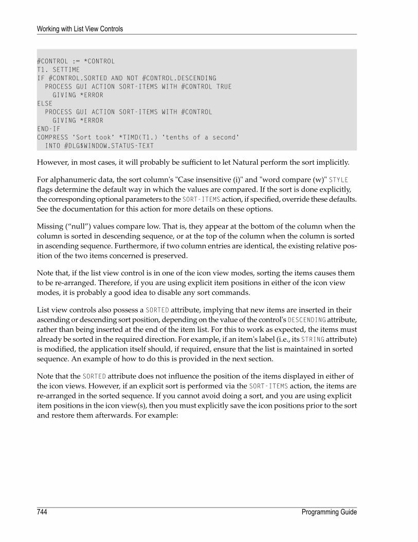
#CONTROL := *CONTROLT1. SETTIMEIF #CONTROL.SORTED AND NOT #CONTROL.DESCENDING
PROCESS GUI ACTION SORT-ITEMS WITH #CONTROL TRUEGIVING *ERROR
ELSEPROCESS GUI ACTION SORT-ITEMS WITH #CONTROL
GIVING *ERROREND-IFCOMPRESS 'Sort took' *TIMD(T1.) 'tenths of a second'
INTO #DLG$WINDOW.STATUS-TEXT
However, in most cases, it will probably be sufficient to let Natural perform the sort implicitly.
For alphanumeric data, the sort column's "Case insensitive (i)" and "word compare (w)" STYLEflags determine the default way in which the values are compared. If the sort is done explicitly,the corresponding optional parameters to the SORT-ITEMS action, if specified, override these defaults.See the documentation for this action for more details on these options.
Missing (“null”) values compare low. That is, they appear at the bottom of the column when thecolumn is sorted in descending sequence, or at the top of the column when the column is sortedin ascending sequence. Furthermore, if two column entries are identical, the existing relative pos-ition of the two items concerned is preserved.
Note that, if the list view control is in one of the icon view modes, sorting the items causes themto be re-arranged. Therefore, if you are using explicit item positions in either of the icon viewmodes, it is probably a good idea to disable any sort commands.
List view controls also possess a SORTED attribute, implying that new items are inserted in theirascending or descending sort position, depending on the value of the control's DESCENDING attribute,rather than being inserted at the end of the item list. For this to work as expected, the items mustalready be sorted in the required direction. For example, if an item's label (i.e., its STRING attribute)is modified, the application itself should, if required, ensure that the list is maintained in sortedsequence. An example of how to do this is provided in the next section.
Note that the SORTED attribute does not influence the position of the items displayed in either ofthe icon views. However, if an explicit sort is performed via the SORT-ITEMS action, the items arere-arranged in the sorted sequence. If you cannot avoid doing a sort, and you are using explicititem positions in the icon view(s), then youmust explicitly save the icon positions prior to the sortand restore them afterwards. For example:
Programming Guide744
Working with List View Controls

PERFORM SAVE-ITEM-POSITIONSPROCESS GUI ACTION SORT-ITEMS WITH #CONTROL GIVING *ERRORIF #CONTROL.VIEW-MODE = VM-ICON OR
#CONTROL.VIEW-MODE = VM-SMALLICONPERFORM RESTORE-ITEM-POSITIONS
END-IF
where #CONTROL is the handle of the list view control, and where the subroutines defined abovefor saving and restoring the item positions are used. Note that the icons are re-drawn (at their oldpositions), causing some flicker. Therefore, if possible, try to avoid performing a sort whilst thelist view control is in one of the icon view modes. See the section below on label editing for anexample of how this may be done.
Label Editing
The process of label editing for list view controls is the same as for tree view controls. Therefore,for more information on this subject, please refer to the section Label Editing in Tree View andList View Controls.
Note that even if the SORTED attribute is set, the items are not automatically re-sequenced after alabel editing operation has been completed. If this is required, this can be done as shown in theexample below. Firstly, we define some variables for later use:
01 #SORTOBJ HANDLE OF GUI01 #SORT (L)01 #AUTO-ARRANGE (I4)
In addition, it is assumed that the list view control is named #LV-1.
In the list view control's AFTER-EDIT event, we cannot do the re-sequencing asynchronously, asthis would interfere with the (as yet incomplete) editing process. Instead, we simply set the #SORTflag to indicate that the re-sequencing should occur at a later time, after the editing process hasbeen completed:
#SORT := TRUE
In order to decide whether to perform a re-sequencing of the items, wewill need to checkwhetherthe items are already sorted. We will do this by querying the SORTED and DESCENDING attributesof the primary column if the list view has columns, or those of the list view control itself otherwise.The relevant object handle is set in the dialog's AFTER-OPEN event:
745Programming Guide
Working with List View Controls
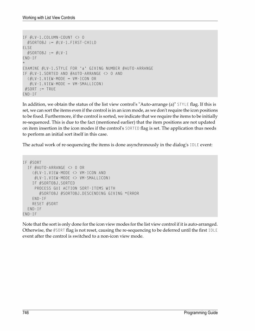
IF #LV-1.COLUMN-COUNT <> 0#SORTOBJ := #LV-1.FIRST-CHILD
ELSE#SORTOBJ := #LV-1
END-IF*EXAMINE #LV-1.STYLE FOR 'a' GIVING NUMBER #AUTO-ARRANGEIF #LV-1.SORTED AND #AUTO-ARRANGE <> 0 AND
(#LV-1.VIEW-MODE = VM-ICON OR#LV-1.VIEW-MODE = VM-SMALLICON)
#SORT := TRUEEND-IF
In addition, we obtain the status of the list view control's "Auto-arrange (a)" STYLE flag. If this isset, we can sort the items even if the control is in an iconmode, aswe don't require the icon positionsto be fixed. Furthermore, if the control is sorted, we indicate that we require the items to be initiallyre-sequenced. This is due to the fact (mentioned earlier) that the item positions are not updatedon item insertion in the icon modes if the control's SORTED flag is set. The application thus needsto perform an initial sort itself in this case.
The actual work of re-sequencing the items is done asynchronously in the dialog's IDLE event:
IF #SORTIF #AUTO-ARRANGE <> 0 OR
(#LV-1.VIEW-MODE <> VM-ICON AND#LV-1.VIEW-MODE <> VM-SMALLICON)IF #SORTOBJ.SORTEDPROCESS GUI ACTION SORT-ITEMS WITH
#SORTOBJ #SORTOBJ.DESCENDING GIVING *ERROREND-IFRESET #SORT
END-IFEND-IF
Note that the sort is only done for the icon viewmodes for the list view control if it is auto-arranged.Otherwise, the #SORT flag is not reset, causing the re-sequencing to be deferred until the first IDLEevent after the control is switched to a non-icon view mode.
Programming Guide746
Working with List View Controls

Multiple Context Menus
If you wish to support just a single context menu for a control, you can simply set the control'sCONTEXT-MENU attribute to the handle of the context menu you wish to display, and leave it set tothis value. However, it is often required to be able to display more than one context menu for aparticular control, whereby this approach is too inflexible.
To address the above problem, the CONTEXT-MENU event was introduced (not to be confused withthe attribute of the same name as mentioned above!). This event (if not suppressed) is raised forthe target control immediately before its CONTEXT-MENU attribute is evaluated, allowing the applic-ation to dynamically set this attribute to the handle of the appropriate context menu first.
As an example, assume thatwe have defined two contextmenus in the dialog editor: one containingitem-related commands, #CTXMENU-ITEMS, and one containing generic commands (e.g., forswitching the view mode for a list view control), #CTXMENU-DEFAULT. In this case, the followingCONTEXT-MENU event could be used:
#CONTROL := *CONTROLIF #CONTROL.SELECTED-SUCCESSOR <> NULL-HANDLE
#CONTROL.CONTEXT-MENU:= #CTXMENU-ITEMSELSE
#CONTROL.CONTEXT-MENU := #CTXMENU-DEFAULTEND-IF
where the following local data definition is assumed:
01 #CONTROL HANDLE OF GUI
In this example, the context menu #CTXMENU-ITEMSwill be displayed if the user right clicks at aposition occupied by an item, or #CTXMENU-DEFAULT otherwise.
Of course, this technique can be refined further to display context menus specific to the type(s) ofthe selected item(s).
747Programming Guide
Working with List View Controls

Drag and Drop
Drag and drop may be used for re-positioning items within a list view control, as well as for datatransfer to and fromotherwindows. There is nodifference between the two cases. The re-positioningscenario is merely a special case where the drop is made in the same list view control in which thedrag was initiated.
The basic technique for providing drag and drop support is described in the section Using theClipboard and Drag and Drop. In particular, it should be noted that it is still necessary to placesome data on the drag and drop clipboard even if it is only required to support re-positioning ofthe items within the control, in order to inform Natural that drag and drop should be initiated.Secondly, there is a caveat specific to list view controls, in that the re-positioning of items canchange the origin of the list view control, so that the top near corner of the list view control's displayarea may no longer begin at the default origin of (0, 0).
The following example provides some code for demonstrating the use of drag and drop with thelist view control, in order to support the following operations:
1. Re-positioning of list view items.
2. Dragging and dropping text from another application (e.g. WordPad) onto a list view item inorder to change its label.
The first step is to ensure that the drag and drop modes are set correctly for the list view control.In the List View Control Attributeswindow in the dialog editor, set theDragmode selection boxto "Move" and theDropmode selection box to "Copy+Move". This causes the control's DRAG-MODEand DROP-MODE attributes to be set to DM-MOVE and DM-COPYMOVE, respectively, in the generatedsource code for the dialog.
Next, the required local variables that are going to be used below must be defined:
01 #CONTROL HANDLE OF GUI01 #DROP-ITEM HANDLE OF GUI01 #ITEM HANDLE OF GUI01 #SELECTED (L)01 #AVAIL (L)01 #X (I4)01 #Y (I4)01 #ORIG-X (I4)01 #ORIG-Y (I4)
Having done this, we can write the necessary event handlers. The logical place to start is with theBEGIN-DRAG event:
Programming Guide748
Working with List View Controls
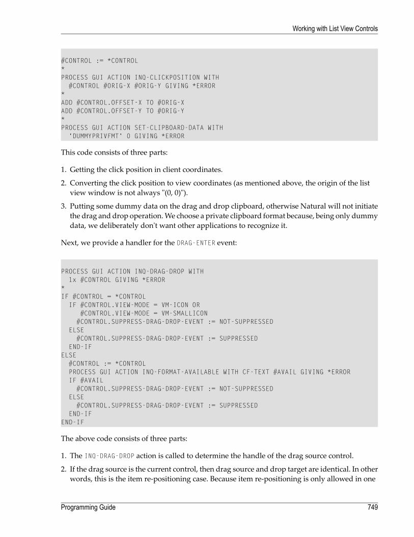
#CONTROL := *CONTROL*PROCESS GUI ACTION INQ-CLICKPOSITION WITH
#CONTROL #ORIG-X #ORIG-Y GIVING *ERROR*ADD #CONTROL.OFFSET-X TO #ORIG-XADD #CONTROL.OFFSET-Y TO #ORIG-Y*PROCESS GUI ACTION SET-CLIPBOARD-DATA WITH
'DUMMYPRIVFMT' 0 GIVING *ERROR
This code consists of three parts:
1. Getting the click position in client coordinates.
2. Converting the click position to view coordinates (as mentioned above, the origin of the listview window is not always "(0, 0)").
3. Putting some dummy data on the drag and drop clipboard, otherwise Natural will not initiatethe drag and drop operation.We choose a private clipboard format because, being only dummydata, we deliberately don't want other applications to recognize it.
Next, we provide a handler for the DRAG-ENTER event:
PROCESS GUI ACTION INQ-DRAG-DROP WITH1x #CONTROL GIVING *ERROR
*IF #CONTROL = *CONTROL
IF #CONTROL.VIEW-MODE = VM-ICON OR#CONTROL.VIEW-MODE = VM-SMALLICON#CONTROL.SUPPRESS-DRAG-DROP-EVENT := NOT-SUPPRESSED
ELSE#CONTROL.SUPPRESS-DRAG-DROP-EVENT := SUPPRESSED
END-IFELSE
#CONTROL := *CONTROLPROCESS GUI ACTION INQ-FORMAT-AVAILABLE WITH CF-TEXT #AVAIL GIVING *ERRORIF #AVAIL
#CONTROL.SUPPRESS-DRAG-DROP-EVENT := NOT-SUPPRESSEDELSE
#CONTROL.SUPPRESS-DRAG-DROP-EVENT := SUPPRESSEDEND-IF
END-IF
The above code consists of three parts:
1. The INQ-DRAG-DROP action is called to determine the handle of the drag source control.
2. If the drag source is the current control, then drag source and drop target are identical. In otherwords, this is the item re-positioning case. Because item re-positioning is only allowed in one
749Programming Guide
Working with List View Controls

of the icon views, we unsuppress the DRAG-DROP event to allow the drop in this case. Otherwise,we suppress this event in order to prohibit a drop such that the “no drop” drag cursor appears.Note that we could have also prevented a drag from occuring at all by not putting the data onthe drag and drop clipboard in this case. However, although not demonstrated in this example,it is often desired to drag one or more items from a list view control to another window, evenif the source control is in list or report view mode, for which the above code provides a betterbasis.
3. If the drag source and drop target are different, an attempt is being made to transfer data fromanother window. In this case, we check to see if data is available in the required format, CF-TEXT, and allow the drop if so. Otherwise the drop is prohibited.
To provide drop emphasis during the dragging of external data across the list view control, aDRAG-OVER event handler is supplied:
PROCESS GUI ACTION INQ-DRAG-DROP WITH1X #CONTROL 1X #X #Y GIVING *ERROR
*IF #CONTROL <> *CONTROL
#CONTROL := *CONTROLIF #CONTROL.SUPPRESS-DRAG-DROP-EVENT = NOT-SUPPRESSED
PROCESS GUI ACTION INQ-ITEM-BY-POSITION WITH#CONTROL #X #Y #ITEM GIVING *ERROR
IF #ITEM <> #DROP-ITEMIF #DROP-ITEM <> NULL-HANDLE
#DROP-ITEM.SELECTED := #SELECTEDEND-IF#DROP-ITEM := #ITEMIF #DROP-ITEM <> NULL-HANDLE
#SELECTED := #DROP-ITEM.SELECTED#DROP-ITEM.SELECTED := TRUE
END-IFEND-IF
END-IFEND-IF
The above code performs the following:
1. The INQ-DRAG-DROP action is called to determine the handle of the drag source control and thecurrent drop position.
2. If the drag source and drag target are identical (item re-positioning), no further action is taken,as no drop emphasis is required in this case. Otherwise the INQ-ITEM-BY-POSITION action isused to find the list view item (if any) at the current drop position.
3. The current target item (“drop item”) is tracked in #DROP-ITEM. Every time this changes, thecurrent selection state of the new drop item is first checkpointed in #SELECTED, and then theitem is selected to provide the drop emphasis by setting its SELECTED attribute to TRUE. In additionthe selection state of the old drop item (if any) is restored to its previously checkpointed value.
Programming Guide750
Working with List View Controls
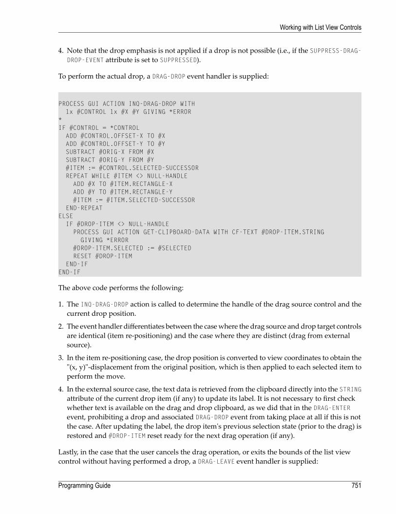
4. Note that the drop emphasis is not applied if a drop is not possible (i.e., if the SUPPRESS-DRAG-DROP-EVENT attribute is set to SUPPRESSED).
To perform the actual drop, a DRAG-DROP event handler is supplied:
PROCESS GUI ACTION INQ-DRAG-DROP WITH1x #CONTROL 1x #X #Y GIVING *ERROR
*IF #CONTROL = *CONTROL
ADD #CONTROL.OFFSET-X TO #XADD #CONTROL.OFFSET-Y TO #YSUBTRACT #ORIG-X FROM #XSUBTRACT #ORIG-Y FROM #Y#ITEM := #CONTROL.SELECTED-SUCCESSORREPEAT WHILE #ITEM <> NULL-HANDLE
ADD #X TO #ITEM.RECTANGLE-XADD #Y TO #ITEM.RECTANGLE-Y#ITEM := #ITEM.SELECTED-SUCCESSOR
END-REPEATELSE
IF #DROP-ITEM <> NULL-HANDLEPROCESS GUI ACTION GET-CLIPBOARD-DATA WITH CF-TEXT #DROP-ITEM.STRINGGIVING *ERROR
#DROP-ITEM.SELECTED := #SELECTEDRESET #DROP-ITEM
END-IFEND-IF
The above code performs the following:
1. The INQ-DRAG-DROP action is called to determine the handle of the drag source control and thecurrent drop position.
2. The event handler differentiates between the casewhere the drag source and drop target controlsare identical (item re-positioning) and the case where they are distinct (drag from externalsource).
3. In the item re-positioning case, the drop position is converted to view coordinates to obtain the"(x, y)"-displacement from the original position, which is then applied to each selected item toperform the move.
4. In the external source case, the text data is retrieved from the clipboard directly into the STRINGattribute of the current drop item (if any) to update its label. It is not necessary to first checkwhether text is available on the drag and drop clipboard, as we did that in the DRAG-ENTERevent, prohibiting a drop and associated DRAG-DROP event from taking place at all if this is notthe case. After updating the label, the drop item's previous selection state (prior to the drag) isrestored and #DROP-ITEM reset ready for the next drag operation (if any).
Lastly, in the case that the user cancels the drag operation, or exits the bounds of the list viewcontrol without having performed a drop, a DRAG-LEAVE event handler is supplied:
751Programming Guide
Working with List View Controls
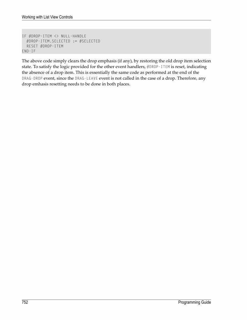
IF #DROP-ITEM <> NULL-HANDLE#DROP-ITEM.SELECTED := #SELECTEDRESET #DROP-ITEM
END-IF
The above code simply clears the drop emphasis (if any), by restoring the old drop item selectionstate. To satisfy the logic provided for the other event handlers, #DROP-ITEM is reset, indicatingthe absence of a drop item. This is essentially the same code as performed at the end of theDRAG-DROP event, since the DRAG-LEAVE event is not called in the case of a drop. Therefore, anydrop emhasis resetting needs to be done in both places.
Programming Guide752
Working with List View Controls

94 Working with Nested Controls
■ Introduction .................................................................................................................................. 754■ Which Control Types can be Containers? ........................................................................................... 755■ Creating a Nested Control ............................................................................................................... 755■ Multiple Selection, Control Sequence and Clipboard Operations .............................................................. 756
753

Introduction
It is possible to create controls as children of other controls in addition to so-called “top-level”controls, which are direct children of the dialog. Such controls are referred to as nested controls.The parent control is referred to as the container. We will also use the term siblings to refer to aset of child controls which all have the same parent. Clearly, there can be many different sets ofsibling controls within a control hierarchy.
Creation of a control hierarchy enables the Natural programmer to group together controls suchthat they can be manipulated more easily and more efficiently within a Natural program. Thefollowing list describes the characteristics of nested controls:
■ Their position is relative to the client area of the container control instead of relative to the dialog.■ Their display is clipped to their respective ancestor windows. This means that the areas of thenested control that are outside the boundary of its container are not visible. The dialog editordoes not allow dragging of nested controls outside of the container.
■ Nested controls are always displayed in front of their container control, regardless of their pos-ition in the control sequence.
■ Nested controls are moved with their container control. This applies at both edit-time in thedialog editor (when the container is dragged) and at runtime (when the container's RECTANGLE-X and/or RECTANGLE-Y attributes are modified).
■ Nested controls are hidden when the container control is hidden, even though the VISIBLE at-tribute of the nested control remains unchanged.
■ Nested controls are disabled at runtime when the container control is disabled, even thoughthe ENABLED attribute of the nested control remains unchanged and even though the controldoes not become grayed.
■ Nested controls are deleted when the container control is deleted.
Note: Natural does not impose any arbitrary limits on the number of levels that a controlhierarchymay contain. The level number for a particular control is displayed together withthe control's name in the dialog editor status bar combo box.
Programming Guide754
Working with Nested Controls

Which Control Types can be Containers?
Not all control types are capable of acting as a container. It is not possible to create a control as achild of an input field, for example. There are currently three types of container control supportedby Natural:
■ Group frames that have the (new) "container" style set. This can be changed in the dialog editor(via its attributes window) after the group frame has been created. If a group frame is convertedto a container, all controls that are spatially containedwithin it aremoved in the control hierarchyto become descendants of the group frame. If a group frame is converted to a non-container, alldirect children of the group frame are moved up a level in the hierarchy to become siblings ofthe group frame.
■ ActiveX controls which are marked as "OLEMISC_SIMPLEFRAME" in the registry. This flag isfixed by design for a particular ActiveX control class.
■ Control boxes. This control type is always a control container. Indeed, that is its entire purposein life. See the sectionWorking with Control Boxes for more information.
Creating a Nested Control
Nested controls are created in the dialog editor in the same way as non-nested controls are. If,during control insertion, the initial left mouse button click is determined to be over a containercontrol, the new control is created automatically byNatural as a child of that container. Even beforethe mouse button is clicked in insert mode, the dialog editor's status bar is continually updatedwith the container-relative mouse co-ordinates as the mouse cursor traverses the dialog.
In addition, nested controls can be indirectly created within the dialog editor when convertinggroup frames to containers as described above.
At runtime, nested controls can be created dynamically, via the PROCESS GUI ACTION ADD statementfor the nested control, by specifying the PARENT attribute as the handle of the required containercontrol instead of the handle of the dialog. The nested control's position (RECTANGLE-X and RECT-ANGLE-Y attributes) should be specified relative to the container's client area. The client area of acontrol is the internal area of a control, excluding frame components such as 3-D borders, single-pixel frames resulting from use of the "Framed" style, and a control's scroll bars.
755Programming Guide
Working with Nested Controls

Multiple Selection, Control Sequence and Clipboard Operations
The dialog editor prohibits selection of multiple controls which do not have the same parent (i.e.,are not all siblings of each other). This applies regardless of whether multiple controls are selectedvia “rubber banding” (marking of a regionwith the left mouse button held down) or via extendedselection (holding down the SHIFT key whilst selecting a control). However, if a selected containercontrol is deleted, then all its direct and indirect children (descendants) are of course implicitly de-leted also, even though they are not explicitly selected. For this reason, a clipboard cut operationalways copies the selected control(s) and all descendant controls (if any) to the clipboard. For aclipboard copy operation, it is not clear whether to copy the container alone, or the container plusall its descendants. In this case, a message box is displayed, allowing the user to choose betweenthe two options.
The pasting of controls from the clipboard uses the same control sequence (tab order) insertionposition logic as for a control created from scratch. In both cases, the new control is created at aposition in the control sequence immediately following the selected sibling (if any) plus any of itssuccessive descendants. If a control other than a sibling is selected, an “effective sibling” is usedinstead, based on the position of the (active) selected control in the control sequence. The “active”selected control is the selected control (if any) which is highlighted using black (rather than gray)selection handles. If no selection is active, the control is inserted into the control sequence imme-diately preceding the first sibling control, or immediately after its container (or at the front of thecontrol sequence for top-level controls) if the container is empty. Note, however, that the controlsequence is maintained independently of the hierarchy. After a control has been created, it ispossible to explicitly move any control to any position in the control sequence via the ControlSequence command on the Dialogmenu.
The position of the newly-created control in the hierarchy is determined slightly differently inthese two cases. In the case of a control being created from scratch, the container is determinedby searching for the (topmost) container at the position where the left mouse button was pressed.However, in the case of pasting from the clipboard, we have no "(X, Y)"-position which we canuse. In this case, the container is assumed to be the container of the selected control(s), or the dialogitself if no controls are selected. This means that if, for example, it is desired to copy and paste acontrol from one container to another, a control within the second containermust be selected priorto the paste, not the container itself. If the second container is empty, this requires temporary cre-ation of a dummy child control first, which can be deleted after the paste operation is complete.
Deletion of controls also deletes any of their descendant controls.
With the introduction of nested controls, the Select All command has been changed to operate inthe following manner:
■ If no control is currently selected, the command selects all top-level controls.■ Otherwise, all other controls that are siblings of the currently selected one(s) are additionallyselected.
Programming Guide756
Working with Nested Controls

Thus, in the common case where only one level of hierarchy is in use, the Select All commandcontinues, as before, to select all dialog controls.
757Programming Guide
Working with Nested Controls

758

95 Working with a Dynamic Information Line
Event-driven applications aremuchmore user-friendlywhen text in the dynamic information line(DIL) explains the dialog element that currently has the focus. A dialog element has the focus ifit can receive the end user's keyboard input.
You have two options to relate a dialog element to a DIL text:
■ Use the dialog editor (most likely because it is the easiest way); or■ use Natural code to specify everything dynamically.
When you use the dialog editor, you will have to go through the following steps:
1. Set the attribute HAS-DIL to TRUE for the dialog by marking the Dyn. Info Line entry in theDialog Attributeswindow.
2. Set the attribute DIL-TEXT to "diltextstring" for the dialog element. Choose the Source...button to the right of theDILText: entry in the attributeswindow. ThewindowSpecify attributeSource appears. Choose one of the attribute sources and enter the text in theValue field. Ensurethat "diltextstring" explains the dialog element's usage in a short phrase.
When you use Natural code, the above two steps may look like this:
...PERSDATA-DIALOG.HAS-DIL := TRUE /* Set HAS-DIL To TRUE#PB-1.DIL-TEXT := 'DILTEXTSTRING' /* Assign the text string...
Note: The STATUS-TEXT and the DIL-TEXT are displayed in the same area if the dialog hasa status line and a text is displayed on the DIL.
759

760

96 Working with Spin Controls
■ Introduction .................................................................................................................................. 762■ Up-Down Control ........................................................................................................................... 762■ Buddy Control ............................................................................................................................... 762■ Date and Time Formats .................................................................................................................. 763■ Inputting Dates and Times ............................................................................................................... 764■ Null Values ................................................................................................................................... 765■ Calendar Colors and Font ............................................................................................................... 765
761
Introduction
A spin control consists of a pair of vertically-opposed arrow buttons known as an “up-down”control, optionally with an associated input field control known as a “buddy” control. The spincontrol has an associated integer range and current position. The buddy control (if present) displaysthe contents relating to the current position. The current position may be changed either by usingthe arrow buttons, the up and down cursor keys, or by typing the value directly into the buddyinput field (if available and modifiable).
Up-Down Control
The up-down control allows the user to explicitly scroll through the spin control's integer range.The up-down control's buttons can also be implicitly selected by using the up arrow and downarrow cursor keys. Holding down the button or key causes the value to be incremented or decre-mented repeatedly, cycling round to the opposite end of the range when the corresponding limitis reached, if the control's "Wrap (w)" style is set. Initially, the incrementation or decrementationstep is 1, but this increases after a few seconds. This acceleration may be disabled or modified viathe SET-ACCELERATION action.
The control's range may be defined by setting its MIN and MAX attributes. The control's current po-sitionwithin this rangemay be programmatically set or obtained by setting or querying the POSI-TION attribute value, respectively.
Whenever the current position is changed by the user, a CHANGE event is raised for the control (ifnot suppressed). This event is not raise if the control's value is changed programatically. Alternat-ively, if a buddy input field control is present, the CHANGE event of the buddy control can be used.
Buddy Control
If the control's "Left align (l)" or "Right align (r)" style flag is set, the spin control contains an inputfield, known as the buddy control, which on the right or left of the up-down control respectively(the alignment relates to the up-down control, not to the buddy control).
The buddy control is a child of the spin control, and appears as a standard Natural input fieldcontrol. This gives theNatural programmer access to all the features available for standalone inputfield controls. For example, the buddy control can be made to accept only digits and/or be madenon-modifiable, for example.
If the spin control's "Set buddy (s)" style is set, the buddy control is automatically updated withthe current position of the up-down control when the current position is changed. Otherwise, the
Programming Guide762
Working with Spin Controls

contents of the buddy control mus be updated manually in response to the spin control's CHANGEevent.
Date and Time Formats
By default, the date and time information is displayed according to the date and time formatsdefined for the current regional settings. BecauseWindows provides two alternative date formats,one long and one short (both of which may be changed by the user), and because the short dateformat may not contain century information, one of three STYLE flags determines which of thestandard date formats should be used. These (mutually exclusive) formats are:
■ "Short date (s)", implying that the standard short date format for the current regional settingsshould be used.
■ "Century date (c)", implying that the standard short date format for the current regional settingsshould be used, but extended to provide century information if this is not already the case. Notethat in many cases, the short date format already includes century information, in which casethis style does not change the appearance of the date.
■ "Long date (d)", implying that the standard long date format for the current regional settingsshould be used.
In addition, the "Time (t)" style flag is provided in order to indicate that the control should displaytime (instead of date) information.
If these standard formats are not sufficient, they can be overridden by proving a custom formatstring using the EDIT-MASK attribute. Note, however, that the format string specifiers do not cor-respond to those used for edit masks elsewhere within Natural. The following table lists theavailable specifiers and their meanings:
DescriptionSpecifier
The one- or two-digit day.d
The two-digit day. Single-digit day values are preceded by a zero.dd
The three-character weekday abbreviation.ddd
The full weekday name.dddd
The one- or two-digit hour in 12-hour format.h
The two-digit hour in 12-hour format. Single-digit values are preceded by a zero.hh
The one- or two-digit hour in 24-hour format.H
The two-digit hour in 24-hour format. Single-digit values are preceded by a zero.HH
The one- or two-digit minute.m
The two-digit minute. Single-digit values are preceded by a zero.mm
The one- or two-digit second.s
763Programming Guide
Working with Spin Controls

DescriptionSpecifier
The two-digit second. Single-digit values are preceded by a zero.ss
The one- or two-digit month number.M
The two-digit month number. Single-digit values are preceded by a zero.MM
The three-character month abbreviation.MMM
The full month name.MMMM
The one-letter AM/PM abbreviation (that is, AM is displayed as "A").t
The two-letter AM/PM abbreviation (that is, AM is displayed as "AM").tt
The last two digits of the year (that is, 2005 would be displayed as "05").yy
The full year (that is, 2005 would be displayed as "2005").yyyy
In addition, any characters in quotes are displayed exactly as specified. To specify the quotecharacter itself within a quoted string, two consecutive single quote characters should be used.Spaces and punctuation marks (such as the comma) do not need to be quoted.
For example, in order to display the string "John's birthday is Friday, December 31, 1969", the DTPcontrol's EDIT-MASK attribute would be set to "'John''s birthday is' dddd, MMMM d, yyyy".
Inputting Dates and Times
The DTP control provides several ways of modifying the specified information:
■ By the user, by entering numerical information (day numbers, etc.) directly.■ By the user, by incrementing or decrementing the selected field (e.g. day number, month name)via the + or - keys, respectively.
■ By the user, if the DTP control has either the "Time (t)" or "Up-down (u)" style, by selecting therequired field and incrementing or decrementing the value via the up-down (“spin”) control.
■ By the user, if the DTP control is using a month calendar, by pressing the down arrow to openthe month calendar and navigating to the required date. Unlike the above method, this methodupdates all date fields simultaneously.
■ Programmatically, by updating the TIME attribute with the required date or time.
For example, to set the date or time in a DTP control to the current date or time, use the followingassignments:
Programming Guide764
Working with Spin Controls

#DTP-1.TIME := *DATX
or
#DTP-1.TIME := *TIMX
respectively, where #DTP-1 is assumed to be the handle of the DTP control.
Note that the DTP control stores both date and time information, even though it only allowsediting of the date or time component, depending on the control's style.
Null Values
If the "Allow 'no value' (n)" style is specified for the DTP control, the control displays a check box.If this check box is unchecked, the interpretation is that there is no date or time associated withthe control. The application can test for this state by querying the control's CHECKED attribute. Itcan also revert the control to the “no value” state by setting the CHECKED attribute back to UNCHECKED.Note that it is, however, not possible to explicitly set the CHECKED attribute to CHECKED, as this isdone implicitlywhenever a date or time is applied to the control. Furthermore, the CHECKED attributemay not be set at all for DTP controls without the "Allow 'no value' (n)" style.
Calendar Colors and Font
The colors and font used by the month calendar (if any) associated with the DTP control may bechanged by use of the SET-AUX-COLOR and SET-AUX-FONT actions, respectively.
765Programming Guide
Working with Spin Controls

766
97 Working with a Status Bar
In a similar way as the dynamic information line, the status barmakes an event-driven applicationmore user-friendly.
The programmer has two options to relate a dialog element to a status bar:
■ use the dialog editor (most likely because it is the easiest way); and■ use Natural code to specify everything dynamically.
When you use the dialog editor, you will have to:
■ Set the attribute HAS-STATUS-BAR to TRUE for the dialog by marking the Status Bar entry in theDialog Attributeswindow. The HAS-STATUS-BAR attribute determines whether the status barmay be modified. If HAS-STATUS-BAR is false, but HAS-DIL is true, the status bar appears, but isonly used as dynamic information line.
When you use Natural code, the above step may look like this:
...PERSDATA-DIALOG.HAS-STATUS-BAR := TRUE /* Set HAS-STATUS-BAR To TRUEPERSADTA-DIALOG.STATUS-TEXT := 'HELLO' /* Set the text to 'Hello'...
Note: The STATUS-TEXT and the DIL-TEXT are displayed in the same area if the dialog hasa status line and a text is displayed on the DIL.
767

768

98 Working with Status Bar Controls
■ Introduction .................................................................................................................................. 770■ Creating a Status Bar Control ........................................................................................................... 770■ Using Status Bar Controls without Panes ............................................................................................ 770■ Outputting Text to a Status Bar Control .............................................................................................. 771■ Sharing a Status Bar in an MDI Application ......................................................................................... 772■ Pane-specific Context Menus ........................................................................................................... 773
769

Introduction
Note: Status bar controls are not to be confusedwith the traditional dialog status bar whichis created by selecting the status bar check box in the Dialog Attributeswindow in thedialog editor, or by setting the dialog's HAS-STATUS-BAR attribute at run-time. If you areusing status bar controls, you should leave the status bar check box unchecked and not setthe HAS-STATUS-BAR attribute.
Creating a Status Bar Control
Status bar controls are created in the dialog editor in the same way as other standard controls(such as list boxes or push buttons) are. That is, they are either created statically in the dialog ed-itor via the Insertmenu or by drag and drop from the Insert tool bar, or dynamically at run-timeby using a PROCESS GUI ACTION ADD statement with the TYPE attribute set to STATUSBARCTRL.
Unlike most other control types, status bar controls cannot be nested within another control andcannot be created within an MDI child dialog. In an MDI application, the status bar control(s)must belong to the MDI frame dialog.
A status bar control may have zero or more panes associated with it. Panes may be defined in thedialog editor from within the status bar control's attribute window, or at run-time by performinga PROCESS GUI ACTION ADD statement with the TYPE attribute set to STATUSBARPANE.
Using Status Bar Controls without Panes
A status bar controlwithout panes offers restricted functionality, becausemost attributes providingaccess to the enhanced functionality of status bar controls are only supported for status bar panes.If you wish to do more with a status bar control than simply display a line of text, but don't needto split up the status bar control intomultiple sections, you should create a single pane that occupiesthe full width of the status bar control.
Programming Guide770
Working with Status Bar Controls

Stretchy vs. non-stretchy panes
If panes are defined for a status bar control, it should be decidedwhether each pane should stretch(or contract) when the containing dialog is resized, orwhether it shouldmaintain a constantwidth.The former are referred to here as “stretchy” panes, and the latter as “non-stretchy” panes.
There is no explicit flag in the Status Bar Control Attributeswindow to mark a pane as stretchyor non-stretchy. Instead, any pane defined with a width (RECTANGLE-W attribute) of 0 is implicitlyassumed to be a stretchy pane, whereas any panes with a non-zero width definition are implicitlyassumed to be fixed-width panes of the specified width (in pixels). Because the RECTANGLE-W at-tribute defaults to 0, all panes are initially stetchy when defined in the dialog editor.
The width of a visible stretchy pane is determined by taking the total width available for all panesin the status bar control, subtracting the widths of all visible fixed-width panes, then dividing theresult by the number of visible stretchy panes.
Note: The total availablewidth for all panes normally excludes the sizing gripper, implyingthat the last pane stops short of the gripper, if present. However, if the status bar controlhas exactly one pane, and that pane is a stretchy pane, the full width of the dialog (includingany sizing gripper) is used.
Outputting Text to a Status Bar Control
Text can be output to the status bar control in one of three ways:
1. For status bar controls with panes, by setting the STRING attribute of the pane whose text is tobe set.
2. By setting the STRING attribute of the status bar control itself, which is equivalent to setting theSTRING attribute of the first stretchy pane (if any) for status bar controls with panes.
3. By setting the STATUS-TEXT attribute of the dialog. This is equivalent to setting the STRING at-tribute of the status bar control (if any) identified by the dialog's STATUS-HANDLE attribute.
Note that the last method is often themost convenient for setting themessage text, because it doesnot require a knowledge of the status bar control or pane handles.
Example:
771Programming Guide
Working with Status Bar Controls

DEFINE DATA LOCAL01 #DLG$WINDOW HANDLE OF WINDOW01 #STAT-1 HANDLE OF STATUSBARCTRL01 #PANE-1 HANDLE OF STATUSBARPANEEND-DEFINE...#DLG$WINDOW.STATUS-HANDLE := #STAT-1...#PANE-1.STRING := 'Method 1'...#STAT-1.STRING := 'Method 2'...#DLG$WINDOW.STATUS-TEXT := 'Method 3'
Note: The dialog editor automatically generates code to set the STATUS-HANDLE attribute tothe first status bar control (if any). Therefore, the STATUS-HANDLE attribute only needs to beset explicitly if you are dynamically creating status bar controls, or if you have definedmorethan one status bar control in a dialog, and wish to switch between them.
Sharing a Status Bar in an MDI Application
Because status bar controls cannot be created for MDI child dialogs, it is convenient to not haveto define multiple status bar controls in the MDI frame dialog. An alternative method is to definejust a single status bar, and share it between each child dialog. This can be achieved as follows:
1. Define all possible panes you wish to use in your application within a single status bar controlin the MDI frame dialog.
2. Mark all panes as "shared".
3. Export the handles of all panes to corresponding shadow variables in a GDA, so that the MDIchild dialogs can access them directly.
4. In the COMMAND-STATUS event handler, set the VISIBLE attribute of all panes you wish to displayfor that dialog to TRUE. All other panes will be automatically made invisible.
Note: In the COMMAND-STATUS event, you must also set the ENABLED state of any commands(signals, or menu or tool bar items which do not reference another object via their SAME-ASattribute) associated with the dialog, otherwise they will be automatically disabled. Thecommands associatedwith the dialog are all non-shared commands for theMDI frame andall shared commands for the active MDI child (or MDI frame, if no MDI child dialog isactive).
Programming Guide772
Working with Status Bar Controls

Pane-specific Context Menus
Context menus are defined for the status bar control and not per-pane. However, if you wish toensure that the context menu for a status bar control only appears when the user right clicks aparticular pane, you can associate a context menu with the status bar control, but suppress it ifthe user clicks outside that pane.
Example:
DEFINE DATA LOCAL01 #CTXMENU-1 HANDLE OF CONTEXTMENU01 #STAT-1 HANDLE OF STATUSBARCTRL01 #PANE-1 HANDLE OF STATUSBARPANE01 #PANE-2 HANDLE OF STATUSBARPANE01 #PANE-3 HANDLE OF STATUSBARPANE01 #PANE HANDLE OF STATUSBARPANE01 #X (I4)01 #Y (I4)END-DEFINE...#STAT-1.CONTEXT-MENU := #CTXMENU-1...DECIDE ON FIRST *CONTROL
...VALUE #CTXMENU-1
DECIDE ON FIRST *EVENT...
VALUE 'BEFORE-OPEN'/* Get click position relative to status bar controlPROCESS GUI ACTION INQ-CLICKPOSITION WITH#STAT-1 #X #Y GIVING *ERROR
/* Get pane (if any) at specified positionPROCESS GUI ACTION INQ-ITEM-BY-POSITION WITH#STAT-1 #X #Y #PANE
/* Only show context menu if user clicked in second paneIF #PANE = #PANE-2
#CTXMENU-1.ENABLED := TRUEELSE
#CTXMENU-1.ENABLED := FALSEEND-IF
...END-DECIDE
...END-DECIDE...END
773Programming Guide
Working with Status Bar Controls

Note: If you wish to display a different context menu for different status bar panes, themenu items must be created dynamically in the context menu's BEFORE-OPEN event.
Programming Guide774
Working with Status Bar Controls

99 Working with Tab Controls
■ Creating a Tab Control .................................................................................................................... 776■ Assigning Controls to Tabs .............................................................................................................. 776■ Use of Control Boxes as Tab Control Pages ........................................................................................ 777■ Switching Between Controls Belonging To Different Tabs ....................................................................... 778■ Mixing Tab-dependent and Tab-independent Controls ........................................................................... 779■ Keyboard Navigation ...................................................................................................................... 779■ Tab Switching Events ..................................................................................................................... 780
775

Creating a Tab Control
Tab controls are created in the dialog editor in the same way as other standard controls (such aslist boxes or push buttons) are. That is, they are either created statically in the dialog editor viathe Insertmenu or by drag and drop from the Insert tool bar, or dynamically at run-time by usinga PROCESS GUI ACTION ADD statement with the TYPE attribute set to TABCTRL.
Alternatively, dialogs containing tab controls may be generated with the Dialog Wizard. In thiscase, many of the techniques described in this section are applied automatically by the wizard,and either do not need to be explicitly implemented, or simply need to be extended or “filled-out”,whilst retaining the generated structure. This can significantly reduce the programming effort re-quired.
A tab control may have zero or more tabs associated with it. Tabs may be defined in the dialogeditor from within the tab control's attribute window, or at run-time by performing a PROCESSGUI ACTION ADD statement with the TYPE attribute set to TABCTRLTAB.
Assigning Controls to Tabs
The tab control is a container. However, the individual tabs are not containers, in the Natural im-plementation of this control. When controls are created within the tab control in the dialog editor,the control's PARENT attribute is automatically set to the handle of the tab control, and not to thehandle of the currently active tab (if any). In order to associate a child control with a particulartab, the child control's OWNER attribute is set to the handle of the tab with which the control shouldbe associated. The control is then automatically hidden by Natural when the tab is deactivated,and automatically re-shown when it is re-activated.
Note, however, that the dialog editor only automatically sets the child control's OWNER attribute ifthe tab control's "UI active (U)" STYLE flag is set, which is the default setting. Otherwise the childcontrol's OWNER attribute is left unset (i.e., NULL-HANDLE). In the latter case, the child control is notautomatically shown and hiddenwhen switching between tabs. Note that the "UI active (U)" STYLEhas no effect at run-time.
Programming Guide776
Working with Tab Controls

Use of Control Boxes as Tab Control Pages
As stated above, all child controls within a tab control have a tab control as their parent, regardlessof the tab towhich they belong.Whilst this is sufficient, it may be preferable to separate the controlson different tabs into separate sub-hierarchies.
The most convenient way of achieving this is to create a child control box for each tab to representthe tab “pages”. All other child controls are then created as child controls of the respective controlbox. Assuming that the tab control's "UI active (U)" STYLE flag is set, the control boxes will beautomatically hidden and shown during tab switching, and thus t heir respective child controlswith them (child controls are automatically hidden if any ancestor window is hidden). Otherwise,the program must do the page switching explicitly, as described in the next section.
The control's organization is shown in the following diagram:
As shown in the diagram, each child control box should be transparent, that the tab control'sbackground texture (if any) shows through, and have the "size to parent (z)" STYLE, so that thecontrol boxes automatically exactly fill the interior area of the tab control, both immediately andwhenever the size of the tab control is changed. In addition, each control box should be “exclusive”if the tab control is not UI active, such that only one child control box is visible at any time.
777Programming Guide
Working with Tab Controls

Switching Between Controls Belonging To Different Tabs
Note: This section only relates to tab controls that are not UI active. Otherwise, the controlswitching is done automatically by Natural.
In the dialog editor, this is performed automatically by the dialog editor when a control belongingto an exclusive control box (or the control box itself) is selected, which is not currently being dis-played. The dialog editor makes the currently visible exclusive control box (if any) invisible (thusalso hiding any controls placedwithin it) andmakes the control box containing the selected controlvisible (thus also showing any controls placed within it). This process is independent of how theselection is made (for example, explicitly, from the selection box in the status bar, or implicitly,by simply tabbing through the controls).
Note: If the status bar is not shown, set the Status Bar under the Dialog Editor tab of theOptions dialog opened via the Tools > Options command.
At run-time, the control boxesmust, of course, be shown or hidden in response to the user selectingthe corresponding tab. This can be achieved by querying the active tab in the tab control's CHANGEevent and setting the VISIBLE attribute of the corresponding control box to TRUE. One way ofmaking the tab/control box associations is to store the handle of the control box in the CLIENT-HANDLE attribute of the corresponding tab in the AFTER-OPEN event of the dialog.
For example:
/* Map control boxes to tabs:#TAB-1.CLIENT-HANDLE := #CTLBOX-1#TAB-2.CLIENT-HANDLE := #CTLBOX-2..#TAB-N.CLIENT-HANDLE := #CTLBOX-N
Then, assuming #CONTROL is defined as HANDLE OF GUI, the CHANGE event of the tab control(#TABCTRL-1) could look like this:
/* Get active tab#CONTROL := #TABCTRL-1.SELECTED-SUCCESSOR/* Switch to control box belonging to active tab:#CONTROL := #CONTROL.CLIENT-HANDLEIF #CONTROL <> NULL-HANDLE
#CONTROL.VISIBLE := TRUEEND-IF
Programming Guide778
Working with Tab Controls
Mixing Tab-dependent and Tab-independent Controls
In some situations, it may be desirable to display controls that remain visible, irrespective of whichtab is currently selected.
There are two ways of achieving this:
1. If control boxes are being used, the control boxes can be made smaller in order to cover onlypart of the tab control's interior area, leaving the remaining space available for controls thatshould be permanently displayed. The "size to parent (z)" STYLEmust be switched off for thecontrol boxes.
2. If control boxes are not being used and the tab control is UI active, permanently displayedcontrols may be created by ensuring that the "UI active (U)" STYLE for the tab control is tempor-arily switched off whilst creating the child control(s) that are to be permanently displayed.
If the tab control is not UI active, a two-layer control box hierarchy can be used, where the childcontrol boxes described above are created as child controls of a transparent top-level control box,which in turn is created as a child of the tab control. The top-level control box (which does nothave the "size to parent" flag set), can then be positioned and sized appropriately to define thereplaceable region.
Note: This is very similar to the technique used for wizard dialogs. See the sectionWorkingwith Control Boxes for more information
Keyboard Navigation
There are three methods of navigating between the tabs of a tab control via the keyboard, anycombination of which can be applied simultaneously:
1. If the tab control is assigned the "browsable (z)" STYLE flag, the tab control is included in thetab sequence (i.e., can be navigated to via the TAB key). When the tab control receives the focus,navigation between the tabs is possible via the arrow keys. There is no “wrap-around” betweenthe first and last tabs in this case.
2. The tab captions (STRING attribute)may contain an ampersand (&), indicating that the followingcharacter is a mnemonic character. The tab is selected when the mnemonic character is pressedtogether with the ALT key. This allows for “direct” keyboard navigation to the desired tab.
3. If the dialog has the "Property Sheet (p)" STYLE set, the keyboard shortcuts CTRL+TAB andCTRL+SHIFT+TABmay be used to navigate to the next and previous tab (respectively), with wrap-around.
779Programming Guide
Working with Tab Controls

Note that the focus does not have to be on the tab control or a dialog element within it in orderfor the last technique to work. Starting from the focus control, Natural examines each container(ancestor), until a container (if any) is found that contains one ormore tab controls. If this containercontains exactly one tab control, the keyboard shortcuts are then applied to this tab control. If itcontains two or more tab controls, these shortcuts have no effect. If the dialog does not contain atab control, the shortcuts perform their usual function, as if the "Property Sheet (p)" STYLE had notbeen set.
Note that this default usage of the CTRL+TAB and CTRL+SHIFT+TAB key combinationsmay be overriddenby redefining them via the ACCELERATOR attribute.
Tab Switching Events
Whenever a tab switch is performed (either by the user or programmatically), the following se-quence of events occurs:
1. The currently selected tab receives a LEAVE event, if not suppressed. This event is typically usedfor data validation and/or committing the data on the tab page.
2. The MODIFIABLE attribute of the tab control is then examined. If it is set to FALSE, the tab switchis not performed. The currently selected tab remains selected and no further events are raised.This can be useful if data validation performed during the LEAVE event found an error, whichshould be corrected by the user before continuing.
3. All direct child controls (if any) that have currently selected tab as their OWNER are automaticallyhidden.
4. The new tab is selected.
5. All direct child controls (if any) that have the newly-selected tab as their OWNER are automaticallyshown, if their VISIBLE attribute is set to TRUE.
6. The newly-selected tab receives an ENTER event. If not suppressed. This event is typically usedfor initializing controls on the new tab page.
7. The tab control receives a CHANGE event. This is convenient for tracking tab switches and respond-ing to them without having to modify the event handlers for each tab.
Note that no initial ENTER event is raised for the selected tab when the control is created, and thatthe tab control does not receive an initial CHANGE event either. Furthermore, when the dialog con-taining the tab control is closed, the currently-selected tab does not receive a LEAVE event.
Programming Guide780
Working with Tab Controls
100 Working with Tree View Controls
■ Introduction .................................................................................................................................. 782■ Setting Item Images ....................................................................................................................... 782■ Item Selection ............................................................................................................................... 783■ Item Activation .............................................................................................................................. 783■ Item Data ..................................................................................................................................... 784■ Sorting ........................................................................................................................................ 784■ Label Editing ................................................................................................................................. 785■ Multiple Context Menus .................................................................................................................. 786■ Dynamic Item Creation ................................................................................................................... 786■ Drag and Drop .............................................................................................................................. 788
781

Introduction
A tree view control is used to display data in hierarchical form. Each node in the hierarchy isrepresented internally as a tree view item. The following shows a simple tree view (with optionalcheck boxes) displaying a 3-level hierarchy containing seven tree view items:
The tree view control shown above is specified with the "+/- buttons (b)", "Lines (l)", "Lines at root(r)" and "Check boxes (c)" STYLE flags.
The height of each item and the indentation between levels can be set via the ITEM-H and SPACINGattributes, respectively. If either of these are zero, the default setting is used.
Setting Item Images
Images for the tree view items may be defined by creating and associating an image list controlwith the tree view control, then (for each item) selecting the required image from the image listvia its index and/or image handle, as described in the sectionWorking with Image List Controls.
Please note that it is not necessary to set the image list control's "Large images (L)" style, unlessyou are additionally using the same image list for a list view control, because the tree view controlonly uses small images.
Programming Guide782
Working with Tree View Controls
Item Selection
Unlike the list view control, the tree view control only supports one selected item. The currentselection (if any) may be retrieved by querying the tree view control's (read-only) SELECTED-SUC-CESSOR attribute.
In addition to being selected by the user, items may be selected or deselected programmaticallyby setting or clearing their SELECTED attribute.
When an item is selected, a CLICK event is raised for the list view control (if not suppressed), withthe handle of the corresponding item being set in the control's ITEM attribute.
Item Activation
When a user double-clicks on an item, an ACTIVATE event is raised (unless suppressed) for the treeview control. The application, if it decides to handle this event, normally performs a user-defineddefault action on the selected item, the handle to which may be obtained via either the ITEM orSELECTED-SUCCESSOR attributes of the tree view control. Note that theremay be other, non-default,actions applicable to the selected item, but these are typically accessed via other mechanisms. Forexample, they may be listed (typically along with the default action) in a context menu displayedby the application.
If the "Dbl. click expand (d)" STYLE flag is set, double clicking a tree view item that has child itemsexpands the item in addition to activating it.
The ACTIVATE event can also be triggered via the keyboard. This can be done in either of twoways:
1. By pressing the key or key combination defined for the tree view control's ACCELERATOR attribute.The control need not currently have the focus.
2. By pressing the ENTER key, if the tree view control currently has the focus. This method onlyworks if the dialog neither contains a default pushbutton, nor a pushbuttonwith the "OKButton(O)" STYLE flag set.
In either case, no ACTIVATE event is raised if no item is currently selected.
783Programming Guide
Working with Tree View Controls

Item Data
In order to be able to support sorting correctly (see next section), a tree view item's data does notneed to be alphanumeric, as it is per default, but can be one of any of the pre-defined types sup-ported by the column's FORMAT attribute. In addition, an edit mask can be applied to the item bysetting its EDIT-MASK attribute. The item's label, as seen by the user for the item, is the alphanumericrepresentation of the item's internal data, using the associated edit mask (if any). The conversionbetween the item's internal data and the displayed data is compatible with the MOVE EDITEDstatement if an editmask is supplied. Otherwise, the conversion between the internal and displayeddata, and vice-versa, is compatible with the conversion involved in copying the data to and fromthe Natural stack (see the STACK TOP DATA and INPUT statements). For example, numeric valuesare displayed using the current decimal character (as defined by the DC parameter) if necessary,with a leading minus character if negative, date values are displayed in the format defined by theDTFORM parameter setting, logical values are displayed as an "X" if true and as a blank if false, andso on.
An example of use of a non-alpha tree view item is shown below:
PROCESS GUI ACTION ADD WITHPARAMETERS
HANDLE-VARIABLE = #TVITEM-DATETYPE = TREEVIEWITEMPARENT = #TV-1STRING = '+123.456'FORMAT = FT-DECIMALEDIT-MASK = '+ZZZ,ZZ9.999'
END-PARAMETERS GIVING *ERROR
In this case, the specified item label (STRING attribute value) must of course be a valid number ofa form compatible with the specified edit mask (+ZZZ,ZZ9.999). Internally, the label is convertedto the data type and length corresponding to the specified format, FT-DECIMAL (= P10.5).
Note that it is not possible to access the underlying data for a tree view item directly. The item'sdata can only be set or retrieved via the item's label.
Sorting
Tree view items can either be inserted in sorted sequence or explicitly sorted after insertion, bycalling the SORT-ITEMS action. Items are inserted in ascending alphabetical sequence if either thetree view control or the tree view item being inserted have their SORTED attribute set to TRUE. Inthe latter case, the items are optionally sorted in ascending or descending sequence according totheir internal data (see last section). See the documentation for the SORT-ITEMS action for moreinformation. Note that it is the responsibility of the programmer to ensure that the underlying
Programming Guide784
Working with Tree View Controls

item formats of the items concerned (as defined by the FORMAT attribute) are of comparable types.For example, it is possible to mix integers and floating point values, but not integers and dates.
Label Editing
The process of label editing for tree view controls is the same as for list view controls. Therefore,for more information on this subject, please refer to the section Label Editing in Tree View andList View Controls.
Note that even if the SORTED attribute is set, the items are not automatically re-sequenced after alabel editing operation has been completed. If this is required, this can be done as shown in theexample below. Firstly, we define some variables for later use:
01 #CONTROL HANDLE OF GUI 01 #ITEM HANDLE OF TREEVIEWITEM01 #SORTITEM HANDLE OF TREEVIEWITEM
In addition, it is assumed that the tree view control is named #TV-1.
In the tree view control's AFTER-EDIT event, we cannot do the re-sequencing asynchronously, asthis would interfere with the (as yet incomplete) editing process. Instead, we simply set the#SORTITEM variable to indicate that the re-sequencing should occur at a later time, after the editingprocess has been completed. This only needs to be done if the tree view items are sorted:
#CONTROL := *CONTROL #ITEM := #CONTROL.ITEM IF #CONTROL.SORTED OR #ITEM.SORTED#SORTITEM := #ITEM ELSE #SORTITEM := NULL-HANDLE END-IF
Note that this examples assumes the use of the default (ascending alphabetical) sorting providedby the tree view control iteself.
The actual work of re-sequencing the items is done asynchronously in the dialog's IDLE event:
IF #SORTITEM <> NULL-HANDLE PROCESS GUI ACTION SORT-ITEMS WITH #SORTITEM.PARENTGIVING *ERROR RESET #SORTITEM END-IF
785Programming Guide
Working with Tree View Controls
Multiple Context Menus
If you wish to support just a single context menu for the control, you can simply set the control'sCONTEXT-MENU attribute to the handle of the context menu you wish to display, and leave it set tothis value. However, it is often required to be able to display more than one context menu for listview controls, whereby this approach is too inflexible.
To address the above problem, the CONTEXT-MENU event was introduced (not to be confused withthe attribute of the same name as mentioned above!). This event (if not suppressed) is raised forthe target control immediately before its CONTEXT-MENU attribute is evaluated, allowing the applic-ation to dynamically set this attribute to the handle of the appropriate context menu first.
As an example, assume thatwe have defined two contextmenus in the dialog editor: one containingitem-related commands, #CTXMENU-ITEMS, and one containing generic commands (e.g., forswitching the view mode), #CTXMENU-DEFAULT. In this case, the following CONTEXT-MENU eventcould be used:
#CONTROL := *CONTROL IF #CONTROL.SELECTED-SUCCESSOR<> NULL-HANDLE #CONTROL.CONTEXT-MENU := #CTXMENU-ITEMS ELSE #CONTROL.CONTEXT-MENU:= #CTXMENU-DEFAULT END-IF
where the following local data definition is assumed:
01 #CONTROL HANDLE OF GUI
In this example, the context menu #CTXMENU-ITEMSwill be displayed if the user right clicks at aposition occupied by an item, or #CTXMENU-DEFAULT otherwise.
Of course, this technique can be refined further to display context menus specific to the type(s) ofthe selected item(s).
Dynamic Item Creation
When a tree view item is expanded or collapsed, an EXPAND event or COLLAPSE event (respectively)is raised for the control, if the event is not suppressed. Amongst other things, these events allowtree-view items to be dynamically created and deleted on demand.
For example, the following code demonstrates the dynamic creation of three items in response tothe EXPAND event. It assumes that a dummyplaceholder itemwith an empty STRING attribute valueis already in place at the position where the items should be inserted. The placeholder can eitherhave been statically defined in the dialog editor, or dynamically-defined during the initial tree
Programming Guide786
Working with Tree View Controls

view item creation. The purpose of the placeholder is to ensure that a "+" button (if button displayenabled via the "+/- buttons (b)" STYLE) appears next to the parent node.
The following EXPAND event code assumes that the variable #TGT-ITEM contains the handle of thetree view item under which the dynamic tree view items are to be created:
#CONTROL := *CONTROL#ITEM := #CONTROL.ITEMIF #ITEM = #TGT-ITEM
#TVITEM-DYN := #ITEM.FIRST-CHILDIF #TVITEM-DYN <> NULL-HANDLE AND
#TVITEM-DYN.STRING = ' 'PROCESS GUI ACTION DELETE WITH #TVITEM-DYN GIVING *ERRORFOR #I 1 3COMPRESS 'Dynamic Item' #I INTO #APROCESS GUI ACTION ADD WITH PARAMETERS
HANDLE-VARIABLE = #TVITEM-DYNTYPE = TREEVIEWITEMPARENT = #ITEMSTRING = #A
END-PARAMETERS GIVING *ERROREND-FOR
END-IFEND-IF
where the following local data definitions are assumed:
01 #CONTROL HANDLE OF GUI01 #ITEM HANDLE OF TREEVIEWITEM01 #TVITEM-DYN HANDLE OF TREEVIEWITEM01 #TGT-ITEM HANDLE OF TREEVIEWITEM01 #I (I4)01 #A (A) DYNAMIC
The above code first looks to see whether the item being expanded is the target item. If so, itqueries the STRING attribute of the first child, to find out whether a placeholder is present. If thisis the case, the placeholder is deleted, and three dynamic tree view items are created. The STRINGattribute value for the inserted items is specified on creation, rather than modified afterwards, toensure that the code also works correctly for SORTED tree views.
To save resources, the dynamically-created items could optionally be deleted again in the COLLAPSEevent handler, being replaced by a placeholder item:
787Programming Guide
Working with Tree View Controls

#CONTROL := *CONTROL#ITEM := #CONTROL.ITEMIF #ITEM = #TGT-ITEM
PROCESS GUI ACTION DELETE-CHILDREN WITH #ITEM GIVING *ERRORPROCESS GUI ACTION ADD WITH PARAMETERS /* placeholder
TYPE = TREEVIEWITEMPARENT = #ITEM
END-PARAMETERS GIVING *ERROREND-IF
Drag and Drop
The basic technique for providing drag and drop support is described in the section Using theClipboard and Drag and Drop.
Note that it is the responsibility of the programmer to (if required) highlight the item (if any) underthe mouse cursor by setting its SELECTED attribute, and to restore the original selection (if any) af-terwards.
The following example provides some code for demonstrating a tree view control acting as a droptarget, in order to support dragging and dropping text from another application (e.g. WordPad)onto a tree view item in order to change its label.
The first step is to ensure that the drop mode is set correctly for the tree view control. In the TreeView Control Attributeswindow in the dialog editor, set the Drop mode selection box toCopy+Move. This causes the control's DROP-MODE attribute to be set to DM-COPYMOVE in the generatedsource code for the dialog.
Next, the required local variables that are going to be used below must be defined:
01 #CONTROL HANDLE OF GUI01 #DROP-ITEM HANDLE OF GUI01 #ITEM HANDLE OF GUI01 #SELECTED HANDLE OF GUI01 #AVAIL (L)01 #X (I4)01 #Y (I4)
Having done this, we can write the necessary event handlers. The logical place to start is with theDRAG-ENTER event:
Programming Guide788
Working with Tree View Controls

#CONTROL := *CONTROL#CONTROL.CLIENT-HANDLE := #CONTROL.SELECTED-SUCCESSORPROCESS GUI ACTION INQ-FORMAT-AVAILABLE WITH CF-TEXT #AVAIL GIVING *ERRORIF #AVAIL
#CONTROL.SUPPRESS-DRAG-DROP-EVENT := NOT-SUPPRESSEDELSE
#CONTROL.SUPPRESS-DRAG-DROP-EVENT := SUPPRESSEDEND-IF
The above code first saves the handle of the currently selected item in the control's CLIENT-HANDLEattribute for the purposes of restoring the selection to this item later. The event handler then checkswhether text data is available on the drag-drop clipboard. If it is, the DRAG-DROP event is unsup-pressed in order to allow a drop. Otherwise, we suppress this event in order to prohibit a dropsuch that the “no drop” drag cursor appears.
To provide drop emphasis during the dragging of external data across the tree view control, aDRAG-OVER event handler is supplied:
#CONTROL := *CONTROLIF #CONTROL.SUPPRESS-DRAG-DROP-EVENT = NOT-SUPPRESSED
PROCESS GUI ACTION INQ-DRAG-DROP WITH3X #X #Y GIVING *ERROR
PROCESS GUI ACTION INQ-ITEM-BY-POSITION WITH#CONTROL #X #Y #ITEM GIVING *ERROR
IF #ITEM <> #DROP-ITEM#DROP-ITEM := #ITEMIF #DROP-ITEM <> NULL-HANDLE#DROP-ITEM.SELECTED := TRUE
END-IFEND-IF
END-IF
The above code performs the following:
1. If a drop was disallowed in the DRAG-ENTER event, the event is ignored, as no drag emphasis isrequired in this case.
2. Otherwise, the INQ-DRAG-DROP action is called to determine the current drop position.
3. The INQ-ITEM-BY-POSITION action is used to find the tree view item (if any) at the current dropposition. This item is tracked in #DROP-ITEM.
4. The tree view item (if any) under the cursor is selected to provide the drop emphasis by settingits SELECTED attribute to TRUE.
To perform the actual drop, a DRAG-DROP event handler is supplied:
789Programming Guide
Working with Tree View Controls

IF #DROP-ITEM <> NULL-HANDLEPROCESS GUI ACTION GET-CLIPBOARD-DATA WITH CF-TEXT #DROP-ITEM.STRING
GIVING *ERROREND-IF#CONTROL := CONTROL /* "parameter" for subroutine belowPERFORM RESET-SELECTION
If there is a tree view item representing the drop target, the above code retrieves the text from thedrag-drop clipboard directly into the item's caption. Afterwards, the original selection state of thetree view control is restored. The RESET-SELECTION subroutine used for this purpose can bewrittenas follows:
#ITEM := #CONTROL.CLIENT-HANDLEIF #ITEM <> NULL-HANDLE
/* Restore original selection:#ITEM.SELECTED := TRUE
ELSE/* Nothing was originally selected,/* so clear any existing selection:#ITEM := #CONTROL.SELECTED-SUCCESSOR#ITEM.SELECTED := FALSE
END-IFRESET #DROP-ITEM
To satisfy the logic provided for the other event handlers, #DROP-ITEM is also reset, indicating theabsence of a drop item.
Lastly, in the case that the user cancels the drag operation, or exits the bounds of the tree viewcontrol without having performed a drop, a DRAG-LEAVE event handler is supplied:
#CONTROL := CONTROL /* "parameter" for subroutine belowPERFORM RESET-SELECTION
The above code simply invokes the inline subroutine listed above in order to clear the drop em-phasis (if any), and to restore the original selection state.
Programming Guide790
Working with Tree View Controls
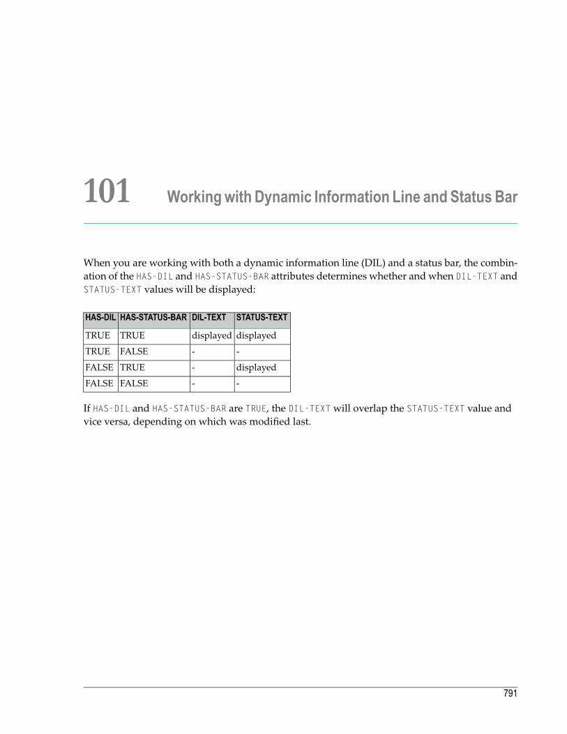
101 Workingwith Dynamic Information Line and Status Bar
When you are working with both a dynamic information line (DIL) and a status bar, the combin-ation of the HAS-DIL and HAS-STATUS-BAR attributes determines whether and when DIL-TEXT andSTATUS-TEXT values will be displayed:
STATUS-TEXTDIL-TEXTHAS-STATUS-BARHAS-DIL
displayeddisplayedTRUETRUE
--FALSETRUE
displayed-TRUEFALSE
--FALSEFALSE
If HAS-DIL and HAS-STATUS-BAR are TRUE, the DIL-TEXTwill overlap the STATUS-TEXT value andvice versa, depending on which was modified last.
791

792

102 Adding a Maximize/Minimize/System Button
To add a Maximize/Minimize/System button to your dialog
■ Open the Dialog Attributeswindow. Check the System Button orMaximizable orMinim-izable entry.
When the System Button entry is checked, the dialog's standard control menu is available. Thisincludes the control menu box (to close the dialog), the title bar, and the Maximize and Minimizebuttons.
793

794
103 Defining Color
You can define colors for dialogs and dialog elements. These can be foreground colors and back-ground colors. To do this, you use the following attributes:
■ BACKGROUND-COLOUR-NAME
■ BACKGROUND-COLOUR-VALUE
■ FOREGROUND-COLOUR-NAME
■ FOREGROUND-COLOUR-VALUE
You can assign only standard colors to the attributes ending with NAME. The attributes ending onVALUE, however, can be assigned customized colors following the RGB model.
You can set colors:
■ in an attributes window, or■ in event-handler code.
You can directly assign a value to the attributes ending with NAME. If you want to assign a valueto an attribute ending with VALUE, you must set the NAME attribute to the value CUSTOM. If you donot set the NAME attribute to the value CUSTOM, the VALUE attribute is ignored.
Examples:
#DIA.BACKGROUND-COLOUR-NAME:= MAGENTA /* Assign a value to a NAME/* attribute
#DIA.BACKGROUND-COLOUR-NAME:= CUSTOM /* Set NAME to CUSTOM#DIA.BACKGROUND-COLOUR-VALUE:= H'FF0000' /* Then assign Red, Green, and
/* Blue values to the VALUE/* attribute (hexadecimal)
795

Note: You can not use all customized colors in all parts of the user interface. Colors in text,for example, must always be monochrome.
When setting a color in an attributes window, you have three possibilities:
■ Use the attribute ending with NAME and leave the value at DEFAULT. You can also do this in code.Your color will then be determined by your color settings in the windowing system.
■ Use the attribute endingwith NAME by pulling down the list box and choose one of the predefinedcolors.
■ Define your own color by using the attribute ending with VALUE.
To define a color
1 Choose the Custom push-button control right of the Background color entry. A dialog boxappears.
2 Select one of the predefined colors or choose theDefine CustomColors push-button control.To set the red, green, and blue values, use the cursor to select the desired color or enter avalue from 1 to 253 in the red, green, and blue value display fields.
3 Choose the Add to Custom Color push button control. To save the newly defined color,choose theOK button in the dialog box. The newly defined color is now selected by default.
4 To set it, close the attributes window.
Programming Guide796
Defining Color
104 Adding Text in a Certain Font
To choose a specific font for the text assigned to a dialog element (for example, the caption on a pushbutton control)
1 Use the dialog element's attributes window.
2 Choose the ... push button control to the right of the Font entry. A dialog box opens.
3 From the list of available fonts, select a font type, for example Times New Roman.
4 From the list of styles available for the font type, select a font style, for example italics.
5 From the list of sizes available for the font type and style, select a font size, for example 10.A sample of your selected font will be displayed.
6 To set it: Close the attributes window.
Note: When adding centered or right-aligned text in a dialog element, the following min-imum heights of the dialog element apply (RECTANGLE-H attribute): 4-point font - height of8; 8-point - 22; 12-point - 24.
Additionally, the dialog editor allows selecting a font for the whole dialog in the dialog attributeswindow. This font is defined in the FONT-STRING attribute and is valid for the dialog and each ofits children. A major advantage of selecting a font for the whole dialog is that if the chosen font istoo large or too small for the dialog layout, you change the FONT-STRING attribute once instead ofgoing through all children of the dialog.
Initially, the FONT-STRING attribute must be set as a parameter while the dialog is being createdwith PROCESS GUI action ADD. If a dialog element inside the dialog contains text with no particularfont assigned to it, this text will be displayed in the font specified by FONT-STRING.
797

798
105 Adding Online Help
From an application written with the dialog editor, you can invoke help for a specified help topicID. Please bear in mind that you will have to create parts of the help associated with these helptopic IDs outside the Natural development environment. You will also have to compile the helpwith the platform-specific help compiler.
To keep an overview of all the different help sections in an application, Natural provides youwiththe help organizer. With this organizer,
■ you assign a help ID (HELP-ID attribute value) to a specific dialog element;■ you write the help text for the associated help topic; this text is converted to a .rtf file to be pro-cessed by the help compiler;
■ you optionally define the help topic's keywords;■ you optionally assign a help compiler macro to the help topic;■ and optionally you add a comment for your internal documentation purposes.
To create a help topic
1 Invoke the help organizer's main dialog.
2 Select a particular dialog element.
3 Generate a new help topic ID.
4 Return to the help organizer main dialog.
5 Assign the generated help topic ID.
6 Enter the external definitions for the help topic ID, such as the help topic text and the topicname.
7 Return to the help organizer main dialog.
799

8 Go to the topic list and see whether this new help topic fits your general organization of thehelp file to be created.
9 Return to the help organizer main dialog.
10 Save everything.
A dialog or dialog element can also be assigned a HELP-ID number independently of the help or-ganizer.
To do so
■ Open the corresponding attributes window. Enter a numeric value in theHelp ID entry.
Youmust use the help topic's .h file tomap the numerical ID that you enter here to the correspond-ing help topic ID (created by a markup in the .hlp file).
Natural expects the help file to be located in the resource (RES) subdirectory of the current libraryor one of the STEPLIBs, or in the directory referred to by the environment variable NATGUI_BMP.By default, Natural searches for a help file with the same name as the current library, but you canexplicitely set the name of the help file via the HELP-FILENAME attribute. If no file extension isspecified, Natural searches for a compiled HTML help file with the extension ".chm" first, then (ifnot found) for a WinHelp help file with the extension ".hlp". Thus, if no file extension is specified,it is possible to upgrade from using WinHelp to using HTML help without changing the Naturalprogram. Note, however, that the Help Organizer only supports WinHelp. If you wish to createHTML help content, you must use an external help authoring tool to do so.
Whenever an end user presses F1 in an active dialog, Natural first queries for a file with the valueof the HELP-FILENAME attribute plus the extension ".hnn" where nn is the Natural language code.If it does not find such a file, it queries for a filewith the value of HELP-FILENAME plus the extension".hlp"
Whenever the dialog element has the focus and the end user presses F1, Natural jumps to this helpID.
Note: When adding online help to an application, it is recommended to assign a HELP-IDnumber to each dialog and to write help texts for the dialogs. If the end user selects a dialogelement towhich no HELP-IDwas assigned and presses F1 to request help, help on the currentdialog will come up. If no HELP-IDwas assigned to a dialog element, Natural will checkwhether the dialog element's parent - the dialog - has a HELP-ID. If not, Natural will checkwhether the dialog's parent - the dialog one level higher - has a HELP-ID, and so on, untilthe top-level dialog is reached.
To build a help file
1 Go to your command promt.
Programming Guide800
Adding Online Help

2 Change to the directory referred to by the environment variable $NATGUI_BMP.
3 Issue the command HCRTF -X helpfilename.
Note: This assures that the directory containing HCRTF.EXE is specified in the PATHenvironment variable.
To test a help file
1 Invoke a dialog in your application.
2 Press F1.
The help topic for the dialog should appear.
Alternatively, the help file can be conveniently built and tested interactively by opening the .hpjfile in the Help Compiler Workshop (HCW.EXE).
To display help in a popup window
1 Check the Popup Help option in the dialog attributes window.
2 Run the dialog.
3 Press F1 with the focus on a control which has a help ID associated with it.
The help topic associated with the focus control should appear in a popup window.
801Programming Guide
Adding Online Help

802

106 Defining Mnemonic and Accelerator Keys
■ Introduction .................................................................................................................................. 804■ Defining a Mnemonic Key ................................................................................................................ 804■ Defining an Accelerator Key ............................................................................................................. 805■ Displaying Accelerator Keys in Menus ............................................................................................... 805
803

Introduction
There are two ways of providing keyboard commands:
■ A mnemonic key is determined by an underlined character in a visible dialog element, for ex-ample a menu item. The end user can select the menu item by pressing “ALT+mnemonic key”,for example ALT+A.
■ An accelerator key is defined in the ACCELERATOR attribute. By pressing this key, the end usercauses a double-click or click event for the dialog element regardless of whether the dialog ele-ment is visible or not, as long as the dialog element is enabled.
Defining a Mnemonic Key
You define a mnemonic key in the dialog element's STRING attribute by specifying "&" before thedesired character. At runtime, the character will be underlined. Example: the STRING attributevalue "E&xplanation" will be displayed as follows at runtime:
Explanation
If you define a mnemonic key with a text constant control or a group frame control, and the enduser presses the mnemonic key at runtime, the next dialog element in the control sequence willget the focus. For example, if the next dialog element after a text constant control is an input-fieldcontrol, the text constant control's mnemonic key sets the focus to the input field control.Whenever you disable such an input field control at runtime, you should also disable the corres-ponding text constant control.
You can define mnemonic keys in the STRING attribute of the following types of dialog elements:group frame control, menu item, push button control, radio button control, text constant control,toggle button control, tool bar item.
You can still display an "&" in your runtime STRING by specifying "&&". Example: "A&&B" willbe displayed as "A&B".
Note: In recentWindows versions (e.g.Windows 2000),mnemonic characters are, by default,not underlined until the ALT key is pressed. However, this new behavior can be disabledby the user, such that mnemonic characters are always underlined. For example, this canbe achieved on the English version of Windows 2000 by unchecking theHide Keyboardnavigation indicators until I use theAlt key option under Start/Control Panel/Display/Ef-fects.
Programming Guide804
Defining Mnemonic and Accelerator Keys
Defining an Accelerator Key
You define an accelerator key by setting the ACCELERATOR attribute to a key or a key combinationfor the dialog element, for example to F6 or CTRL+1. If the end user presses the accelerator key, thedouble-click event occurs for the dialog element, or if no double-click event is available, the clickevent occurs. The accelerator key does not work if the corresponding event is suppressed, or ifthe dialog element is disabled.
Standard system accelerators such as ALT+ESC, CTRL+ESC, ALT+TAB and CTRL+ALT+DEL can be definedas accelerators, but do not cause the dialog element's click or double-click event to be triggered.Instead, they cause the associated system functionality to be invoked. The same applies to standardMDI accelerators (such as CTRL+F4 and CTRL+F6) if usedwithinMDI applications and to any acceler-ators belonging to in-place activated servers (e.g. ActiveX controls which currently have the focus).
Note that user-defined accelerator keys overwrite identical user-defined shortcut keys associatedwith desktop items.
If the same accelerator key is associated with more than one dialog element, the dialog elementwhose click or double-click event is triggered is not defined.
A dialog element which references another via its SAME-AS attribute inherits the accelerator of thereferenced object. For example, if a menu item references a signal, and the signal's accelerator isCTRL+ALT+X, then querying the menu item's ACCELERATOR attribute will also return CTRL+ALT+X.However, the accelerator, if pressed,will only trigger a click event for the referenced dialog element(i.e., the signal in this example).
Accelerators of the form ALT+X, where "X" is one of the alphabetic characters, should be avoided,because they are reserved for use as keyboard mnemonics.
Displaying Accelerator Keys in Menus
In order to show accelerators for menu items, the menu text needs to first be appended with a tab(h'09') character and then appendedwith the text for the accelerator. This cannot be done staticallyin the dialog editor's menu editor, because there is no way to enter a tab character into the stringdefinition. However, the accelerators may be appended dynamically using a generic piece of codewhich iterates round all menu items for a dialog. This is illustrated by the following externalsubroutine, which can conveniently be called from within a dialog's AFTER-OPEN event.
805Programming Guide
Defining Mnemonic and Accelerator Keys

DEFINE DATAPARAMETER
1 #DLG$WINDOW HANDLE OF WINDOWLOCAL
1 #CONTROL HANDLE OF GUI1 #COMMAND HANDLE OF GUI
LOCAL USING NGULKEY1END-DEFINE*DEFINE SUBROUTINE APPEND-ACCELERATORS#CONTROL := #DLG$WINDOW.FIRST-CHILDREPEAT UNTIL #CONTROL = NULL-HANDLE
IF #CONTROL.TYPE = SUBMENU OR #CONTROL.TYPE = CONTEXTMENU#COMMAND := #CONTROL.FIRST-CHILDREPEAT UNTIL #COMMAND = NULL-HANDLEIF #COMMAND.ACCELERATOR <> ' 'COMPRESS #COMMAND.STRING H'09' #COMMAND.ACCELERATOR INTO
#COMMAND.STRING LEAVING NO SPACEEND-IF#COMMAND := #COMMAND.SUCCESSOR
END-REPEATEND-IF
#CONTROL := #CONTROL.SUCCESSOREND-REPEATEND-SUBROUTINEEND
This dynamic technique has the advantage that the accelerator does not, in effect, have to be definedtwice (i.e., for the ACCELERATOR and STRING attributes of the menu item).
Note that if the target language is not English, the ACCELERATOR attribute value will probably haveto be translated before being appended to the menu item string.
Programming Guide806
Defining Mnemonic and Accelerator Keys

107 Dynamic Data Exchange - DDE
■ Concepts ..................................................................................................................................... 808■ Developing a DDE Server Application ................................................................................................ 809■ Developing a DDE Client Application ................................................................................................. 810■ Return Codes ............................................................................................................................... 811
807

Concepts
DDE is a protocol defined by Microsoft Corp. to enable different applications to exchange data.This means that, for example, an application written in Natural may exchange data with aspreadsheet, because they are both able to process the DDEprotocol. An application that processesthe DDE protocol communicates with another DDE application via standardized messages. Oneof the applications is defined as the client, the other as the server. Client and server are holding aDDE conversation.
Note: For an overview of DDE concepts and terminology, see your Microsoft Windowsdocumentation.
Data in a DDE conversation is identified by a three-level hierarchy:
■ service,■ topic,■ item.
A DDE conversation is established whenever a client requests a service from a DDE server. A DDEserver offers one or more services to all active applications.
For each service, a DDE server may offer any number of topics. The DDE client then requests aconversation on a topic of a service.
In a conversation on a topic of a service, the DDE client and the DDE server uniquely identify datato be exchanged by an item name.
A DDE server may support a number of services, which in turnmay consist of a number of topics,which themselves may contain a number of items.
With Natural, you can develop both DDE client applications as well as DDE server applications.Youmay, for example, write aNatural DDE client application that requests data from a spreadsheetacting as a DDE server, or you may write a Natural DDE server application that supplies a wordprocessor (DDE client) with data.
To develop DDE client and DDE server applications, the following functionality is provided:
■ A number of NGU-prefixed subprograms in library SYSTEM; these send messages and data asdefined in the parameter data area NGULDDE1
■ a parameter data area (NGULDDE1) which describes the parameters used by the subprogramsin a DDE conversation (the DDE-VIEW);
■ a DDE-Client event and a DDE-Server event which handle DDE messages.
Programming Guide808
Dynamic Data Exchange - DDE
Youdevelop aDDE server application by reacting to theDDE-Server event and by using theNGU-SERVER-prefixed subprograms from library SYSTEM to register services and topics and to sendmessages and data to the DDE client application.
You develop a DDE client application by reacting to the DDE-Client event and by using the NGU-CLIENT-prefixed subprograms from library SYSTEM to initiate conversations and send requestsand other DDE commands to DDE server applications.
You always have to include the parameter data areaNGULDDE1and the local data areaNGULFCT1in your client or server dialog. (You need NGULFCT1 in order to use the NGU-prefixed subpro-grams in library SYSTEM).
Developing a DDE Server Application
The following topics are covered below:
■ Registering/Unregistering Services and Topics■ Getting Data From The Client■ Sending Data To The Client■ Terminating DDE Server Operation
Registering/Unregistering Services and Topics
Before a DDE server application can be addressed by a DDE client application, it must register itsservice names and all supported topics for the services. You use subprogram NGU-SERVER-RE-GISTER to do this for each service/topic the DDE server supports. Registering will usually behandled in the “after open” event of the base dialog.
When registering a service/topic for the first time, youwill need to supplyNaturalwith the dialog-ID of the dialog that will function as the server and that will therefore receive all DDE messagesfrom clients. This is done by setting the DDE-VIEW.CONV-ID to the respective dialog-ID and alsoby setting DDE-VIEW.MESSAGE to the string "DLGID".
Note that at a later time you are able to add more topics to a service or even entirely new services.You can also make a topic unavailable by using subprogram NGU-SERVER-UNREGISTER.
809Programming Guide
Dynamic Data Exchange - DDE
Getting Data From The Client
After successful registration, it is possible that the DDE server application receives DDEmessagesfrom aDDE client applicationwhich is establishing a conversation on a registered topic of a service.
Suchmessages for aDDE server are received in theDDE-Server event of the dialog.At the beginningof the event-handler section, it is necessary to fill the DDE-VIEW with the client's message data.This is done by using subprogram NGU-SERVER-GET-DATA. After reading the data, it will benecessary to act based on the client message received. The possible messages and their meaningare explained in the description of subprogram NGU-SERVER-GET-DATA.
Sending Data To The Client
In many cases, the client message ultimately requires the server to send data to the client. This isachieved by using the subprogram NGU-SERVER-DATA.
Terminating DDE Server Operation
WheneverDDE server operation is supposed to terminate, you use the subprogramNGU-SERVER-STOP. It unregisters all services and terminates all active conversations. You terminate the serverapplication with the CLOSE DIALOG statement.
Developing a DDE Client Application
The following topics are covered below:
■ Connecting With The DDE Server Application■ Using The Services of a DDE Server Application■ Receiving Data From The DDE Server Application■ Disconnecting From The DDE Server Application■ Terminating DDE Client Operation
Connecting With The DDE Server Application
In order to establish a conversation with a DDE server application, a DDE client application mustcall the subprogram NGU-CLIENT-CONNECT with the service and topic name of the server itwants to connect. In order to receive the appropriate DDE events from a server, it is necessary toset the DDE-VIEW.CONV-ID to the client's dialog-ID and also to set DDE-VIEW.MESSAGE to the string"DLGID". The call will return a unique conversation ID in DDE-VIEW.CONV-ID. This value must beset appropriately in all further communication with the server.
Programming Guide810
Dynamic Data Exchange - DDE
Using The Services of a DDE Server Application
The client has several options to use the services of a server once a conversation has been estab-lished. It can
■ request data on a specific item (using NGU-CLIENT-REQUEST),■ send data to the server (using NGU-CLIENT-POKE),■ ask the server to execute a command (using NGU-CLIENT-EXECUTE), or■ establish a warm or hot link to the server (using NGU-CLIENT-ADVISE-HOT, NGU-CLIENT-ADVISE-WARM and NGU-CLIENT-ADVISE-TERM).
Receiving Data From The DDE Server Application
The DDE client will receive data or other messages from the DDE server via the client dialog'sDDE-Client event. Whenever a server has sent a message, this event occurs. Themessage contentsmust first be retrieved using NGU-CLIENT-GET-DATA. This will fill the DDE-VIEW structureappropriately. The clientmust then determinewhichmessage (DDE-VIEW.MESSAGE) has arrivedand react appropriately. The possible messages are listed in the description of subprogramNGU-CLIENT-GET-DATA.
Disconnecting From The DDE Server Application
Whenever the client determines that the conversation is no longer needed, a call toNGU-CLIENT-DISCONNECT must be issued to inform the server that the conversation is to be terminated.
Terminating DDE Client Operation
Whenever the client application terminates or wants to stop using DDE, it needs to call NGU-CLIENT-STOP. This informs Natural to close all active conversations of the client and shut downDDE operation for the application.
Return Codes
Possible return codes are described in this section.
Note: Each error-code description is not necessarily comprehensive. In these cases, the de-scription is marked with an asterisk (*).
811Programming Guide
Dynamic Data Exchange - DDE

MeaningCode
You have specified an incorrect command or command parameter. Ensure that your DDE dataarea is of the correct type and that the command is correct.
-1
The function was processed correctly.0
This value is returned when an application has attempted to initialize with the DDEML librarymore than once. Check the logic of your program.Also ensure that theDDEMLwas exited correctlyduring the last run of the program.
1
This value may be returned from the server-initialize function if you have run the program beforeand not exited the DDEML correctly. It is also returned by a call-back function, whenever therequested service failed.
2
An error occurred in the underlying layer. *
The conversation ID referenced does not represent an active conversation. Check if you havespecified a correct service name.
3
The application could not initialize with the DDE library as the maximum number of instancesare connected.
4
The DDEML communication has not been initialized. You must initialize with the DDEML beforeany DDE activity can take place.
5
Memory allocation problems encountered. This error might occur if the queue of messages foreither part in the conversation becomes too long. *
6
A service, topic or item name was longer than 255 characters. Check if your fields are correctlyspecified for DDE-VIEW and make sure that you are not attempting to place a string longer than255 characters in any one of the above variables.
7
An error occurred in the DDE library. Contact Software AG Support. *8
Parameters passed to this function were illegal. This can be returned by any function call. Checkyour parameters.
9
“Server Type Link” is supported but no call-back function for UNLINK is passed to the functionPIDsRegisterTopic. *
10
An attempt was made to remove a topic for which at least one conversation is still active. Thisincludes trying to unregister a topic for which a conversation still exists.
11
The service/topic referenced has not been registered with the function PIDsRegisterTopic.12
No links were active for the DDE-VIEW.SERVICE when the NGU-Server-Data subprogram wasused. Check your service name and use the DDE-SPY in the SDK Tool Kit to see what services areavailable.
13
The requested type of link is invalid.14
The transaction ID is corrupted. Check the value of your transaction ID in your DDE view.15
The client application requested a conversation and prior to that, no functionwas specified to sendthe data for the links.
16
An asynchronous transaction was requested, but the client application did not specify a functionto send details of the completed transaction. Such a function must be specified when theconversation is initialized.
17
Programming Guide812
Dynamic Data Exchange - DDE

MeaningCode
A synchronous transaction timeout expired. The amount of time taken for your transaction tocompletewas longer than the TIMEOUTvalue in yourDDE-VIEWstructure. Increase the TIMEOUTvalue or set it to "-1" for indefinite waiting.
18
For internal use only.19 - 24
813Programming Guide
Dynamic Data Exchange - DDE

814

108 Object Linking and Embedding - OLE
■ What is OLE in the Natural Context? ................................................................................................. 816■ OLE Documents Support ................................................................................................................ 816■ Embedding and Linking .................................................................................................................. 816■ Visual Editing - In-place Activation ..................................................................................................... 817■ ActiveX Controls Support ................................................................................................................ 818■ OLE Container Control .................................................................................................................... 818■ Attributes, Events and PROCESS GUI Statement Actions ...................................................................... 821
815

What is OLE in the Natural Context?
Natural supports the following OLE technologies:
■ OLE Documents■ OLE Visual Editing (In-place Activation)■ ActiveX Controls
If you are new to OLE, it is highly recommended that you first get a basic overview by referringto one of the various sources available. One such source, for example, is the Microsoft Win32software development kit documentation.
OLE Documents Support
OLE documents is a technology that integrates differentWindows applications seamlessly so thatthe end user can concentrate on the data rather than on handling the different applications. WithOLE you can, for example, embed aWord for Windows document in a Natural dialog. Wheneverthe enduser enters the text container to edit the document, the entireWord functionality is available.Thus, the end user does not have to invoke Word.
OLE Documents Support is provided by the Natural dialog element OLE container control.
TheOLEdocuments technology defines container and server applications. A container applicationis an application that is able to use objects created by a server application. These objects are usedby linking or embedding them. In this context, Natural is the container application because thedialog editor provides an OLE container control. A typical server application is Microsoft Word;the Word documents would then be the objects used by Natural.
Embedding and Linking
■ Linking means that the content of a document is accessed via a link to an external file. This fileis stored in the server's format (for example, a file in .rtf format would be stored in a file systemoutside Natural; the server residing in this external file system would be Microsoft Word).
■ Embedding means that the content of a document is maintained in the container applicationand is stored in the container's internal format. Embedded documents are created■ either by building them from scratch in the container application;■ or by loading an external document.
Programming Guide816
Object Linking and Embedding - OLE

Embedded objects are edited by visual editing (“in-place activation”), whereas linked objectsmustbe opened in an extra server window for editing.
Natural provides the dialog elementOLE container control for embedding and linking documents.Furthermore, Natural provides actions to save and load embedded documents in internal Naturalformat. By default, these embedded objects in internal format are stored and retrieved in the%NATGUI_BMP% directory with a default extension of .neo (Natural Embedded Object).
To display an embedded object with the OLE container control when the dialog starts
1 Invoke the container control's attribute window.
2 Set the Type entry to "Existing OLE Object".
3 Select a file specification in the Name field.
To display an embedded object dynamically at runtime
■ Use the PROCESS GUI statement action OLE-READ-FROM-FILE.
To display a linked object with the OLE container control when the dialog starts
1 Invoke the container control's attribute window.
2 Set the Type entry to "OLE Server".
3 In the Select OLE Server or Document dialog that comes up, select Create From File andselect a file specification.
To display a linked object dynamically at runtime
■ Assign the file specification of the external document to the attribute SERVER-OBJECT.
Visual Editing - In-place Activation
In-place activation means that the end user is able to activate a server application in the containerapplication's window. Such a server application is related to an object embedded in a Naturaldialog's OLE container control. The server application is activated by double-clicking on the OLEcontainer control. The Natural dialog's toolbar and menu-bar control are then merged with theserver application's menu and toolbar. The dialog now contains toolbar items and menu itemsthat enable you to edit the object with the help of the server's functionality.
817Programming Guide
Object Linking and Embedding - OLE

ActiveX Controls Support
ActiveX controls support enables the Natural programmer to use the many third-party ActiveXcontrols inside a Natural dialog. Natural enables you to access the ActiveX controls propertiesand methods direct and to program the ActiveX controls events.
ActiveX controls support is provided by the Natural dialog element “ActiveX control”. For moreinformation, seeWorking with ActiveX Controls.
OLE Container Control
The following topics are covered below:
■ Creating an OLE Container Control■ Creating an OLE Container Control in the Dialog Editor■ Creating an OLE Container Dynamically At Runtime■ Clearing or Deleting an OLE Container At Runtime■ OLE Container Controls And The Dialog's Menu Bar■ Other OLE Container Control Functionality
Creating an OLE Container Control
You can create an OLE container control either statically in the dialog editor or dynamically atruntime.
Creating an OLE Container Control in the Dialog Editor
The OLE container control enables you to integrate server applications. You can integrate serverapplications in the following three ways, as indicated by theObject Information group frame,Type entry of the OLE container control's attributes window.
■ Type: New OLE object. You create an OLE container control that acts as a placeholder for theinsertable object. At runtime, your end user can create the embedded object by starting theserver application. The embedded object can then be saved as Natural embedded object (.neofile).
■ Type: Existing OLE object. Your end user changes an existing embedded object in the OLEcontainer control. The embedded object is saved as Natural embedded object (.neo file).
■ Type: OLE server. You create a native OLE object in your application or you create a link to anexternal object.
Programming Guide818
Object Linking and Embedding - OLE

To create an OLE container control in the dialog editor
1 In the dialog editor main menu, choose Insert, thenOLE Container.
2 Draw a rectangle by holding down the rightmouse button, dragging themouse vertically/ho-rizontally and releasing the mouse button.
An empty OLE container is created.
To display a document in the OLE container when starting the dialog
1 Double-click the OLE container control to invoke the attribute window.
2 In the Type selection box, chooseOLE server for linking an external document. Or chooseExisting OLE object for reading in an embedded object.
3 Choose the ... button to select the external or embedded object file.
Creating an OLE Container Dynamically At Runtime
Before you enter the examples in an event-handler section, declare a handle variable for the OLEcontainer control in the local data area of the dialog:
01 #OCT-1 HANDLE OF OLECONTAINER
Example for creating an OLE container control at runtime and linking an external document:
PROCESS GUI ACTION ADD WITHPARAMETERS
HANDLE-VARIABLE = #OCT-1TYPE = OLECONTAINERSERVER-OBJECT = 'PICTURE.BMP'RECTANGLE-X = 56RECTANGLE-Y = 32RECTANGLE-W = 336RECTANGLE-H = 160PARENT = #DLG$WINDOWSUPPRESS-CLICK-EVENT = SUPPRESSEDSUPPRESS-DBL-CLICK-EVENT = SUPPRESSEDSUPPRESS-CLOSE-EVENT = SUPPRESSEDSUPPRESS-ACTIVATE-EVENT = SUPPRESSEDSUPPRESS-CHANGE-EVENT = SUPPRESSED
END-PARAMETERS GIVING *ERROR
Example for creating an OLE container control at runtime and embedding a Natural embeddedobject:
819Programming Guide
Object Linking and Embedding - OLE

PROCESS GUI ACTION ADD WITHPARAMETERS
HANDLE-VARIABLE = #OCT-1TYPE = OLECONTAINEREMBEDDED-OBJECT = 'SLIDE.NEO'RECTANGLE-X = 56RECTANGLE-Y = 32RECTANGLE-W = 336RECTANGLE-H = 160PARENT = #DLG$WINDOWSUPPRESS-CLICK-EVENT = SUPPRESSEDSUPPRESS-DBL-CLICK-EVENT = SUPPRESSEDSUPPRESS-CLOSE-EVENT = SUPPRESSEDSUPPRESS-ACTIVATE-EVENT = SUPPRESSEDSUPPRESS-CHANGE-EVENT = SUPPRESSEDEND-PARAMETERS GIVING *ERROR
Clearing or Deleting an OLE Container At Runtime
This section contains examples for clearing and deleting an OLE container at runtime.
Before you enter the examples in an event-handler section, declare a handle variable for the OLEcontainer control in the local data area of the dialog:
01 #OCT-1 HANDLE OF OLECONTAINER
Example for clearing (removing the document of) the OLE container control:
PROCESS GUI ACTION CLEAR WITH #OCT-1
Example for deleting the OLE container control:
PROCESS GUI ACTION DELETE WITH #OCT-1
OLE Container Controls And The Dialog's Menu Bar
The menu item attribute MENU-ITEM-OLE can have four different values which detemine if andwhere the menu item in question is displayed during in-place activation of a server.
The menu item attribute MENU-ITEM-TYPE also has the value MT-OBJECTVERBS. This enables you tohave the OLE container control display the available server actions (command verbs) in this menuitem.
Programming Guide820
Object Linking and Embedding - OLE

Other OLE Container Control Functionality
While a document is displayed in an OLE container control, the end user has the possibility toactivate the default command verb of the server by double-clicking inside the OLE containercontrol's rectangle. This is equivalent to executing the PROCESS GUI statement action OLE-ACTIVATE.Furthermore, the end user can select a server command verb by displaying a popup menu. Youdisplay this popupmenu by holding down the right mouse button inside the OLE container. Thenyou select the desired command verb and release the mouse button.
If the MODIFIABLE attribute of an OLE container control is set to FALSE, a double-click on the con-tainer does not start the default command verb of the server and holding down the right mousebutton does not show the popupmenuwith the available server commandverbs (see alsoExecutingStandardized Procedures).
During visual editing (in-place activation), the server uses the Natural dialog for the editing ofthe document. The server does its work as a task on its own and the Natural processing continues.Thus, it is possible to execute event code and, for example, to limit the visual editing to a certaintime by specifying PROCESS GUI ACTION OLE-DEACTIVATE, WITH #OCT-1 in a timer's event section(see also Executing Standardized Procedures).
Attributes, Events and PROCESS GUI Statement Actions
The following sections list all the attributes, events and PROCESS GUI statement actions that applyspecifically to the OLE container control.
Attributes
The OLE-specific attributes provided with the OLE container control are:
■ EMBEDDED-OBJECT
■ ICONIZED
■ OBJECT-SIZE
■ SERVER-OBJECT
■ SERVER-PROGID
■ SUPPRESS-ACTIVATE-EVENT
■ SUPPRESS-CLOSE-EVENT
■ ZOOM-FACTOR
821Programming Guide
Object Linking and Embedding - OLE
Event
This OLE-specific event occurs when a server application is activated:
■ Activate event
PROCESS GUI Statement Actions
The OLE-specific PROCESS GUI statement actions provided with the OLE container control are:
■ OLE-ACTIVATE
■ OLE-DEACTIVATE
■ OLE-GET-DATA
■ OLE-INSERT-OBJECT
■ OLE-READ-FROM-FILE
■ OLE-SAVE-TO-FILE
■ OLE-SET-DATA
Programming Guide822
Object Linking and Embedding - OLE

XI Results Interface
823

824

109 Results Interface
■ Purpose of the Results Interface ....................................................................................................... 826■ Results Window Control Bar Access .................................................................................................. 826■ Tab Handling ................................................................................................................................ 827■ Image Handling ............................................................................................................................. 827■ Context Menu Handling .................................................................................................................. 828■ Command Handling ....................................................................................................................... 828■ Column Handling ........................................................................................................................... 829■ Row Handling ............................................................................................................................... 829■ Data Handling ............................................................................................................................... 830■ Selection Handling ......................................................................................................................... 830
825

Purpose of the Results Interface
The Results Interface enables programmers to display data within the results window of NaturalStudio. See also Results Window in the Using Natural Studio documentation.
Note: The results of the menu commands Find Objects and Cat All are not affected by theResults Interface.
The design and the usage of a tab in the results window can be determined via application pro-gramming interfaces (API). In general, a detailed view with columns and lines is used.
A context menu can be created for each entry, so that after the user-defined tab is shown it can beused for further processing.
This processing has to be defined within two programs:
1. In an update command handler before a context menu is shown.
2. In a command handler if an item is selected.
The application programming interfaces for the Results Interface are USR5001N - USR5017N and canbe found in the library SYSEXT.
An example of the various functions is available in USR5001Pwith the update command handlerin USR5001A and the command handler in USR5001B.
Notes:
1. Modifications of the pre-defined tabs (for example, the tabs with the labels Find Objects andCat All) are not possible with this interface.
2. The results window and the Results Interface can be accessed only from Natural Studio.
Results Window Control Bar Access
The following application programming interface can be used to access the results window controlbar.
Programming Guide826
Results Interface
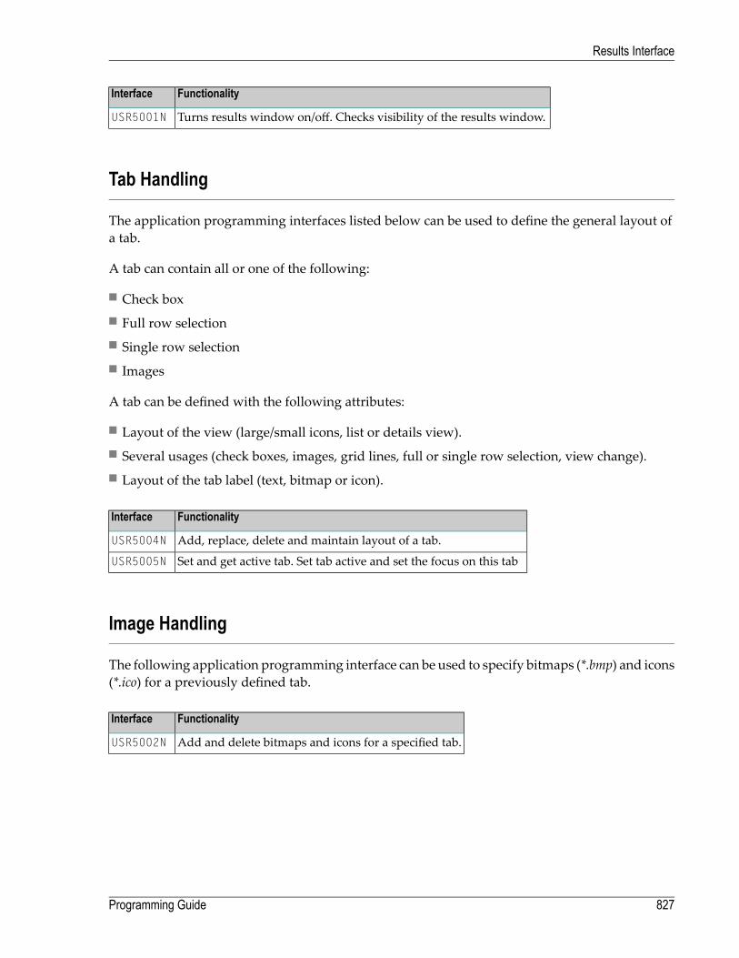
FunctionalityInterface
Turns results window on/off. Checks visibility of the results window.USR5001N
Tab Handling
The application programming interfaces listed below can be used to define the general layout ofa tab.
A tab can contain all or one of the following:
■ Check box■ Full row selection■ Single row selection■ Images
A tab can be defined with the following attributes:
■ Layout of the view (large/small icons, list or details view).■ Several usages (check boxes, images, grid lines, full or single row selection, view change).■ Layout of the tab label (text, bitmap or icon).
FunctionalityInterface
Add, replace, delete and maintain layout of a tab.USR5004N
Set and get active tab. Set tab active and set the focus on this tabUSR5005N
Image Handling
The following application programming interface can be used to specify bitmaps (*.bmp) and icons(*.ico) for a previously defined tab.
FunctionalityInterface
Add and delete bitmaps and icons for a specified tab.USR5002N
827Programming Guide
Results Interface

Context Menu Handling
The following application programming interfaces can be used to specify user-defined contextmenus.
FunctionalityInterface
Add, remove and delete context menus of a tab.USR5003N
Set and get checked/enabled state of context menu items.USR5007N
The hierachy of the context menu must be defined manually.
The following array components can be defined:
DescriptionValueArray Component
1 to 4Type 1 - Context menu handling.2 - Separator line.3 - Begin of submenu.4 - End of submenu.
Free selectable number to identify a certain item in a context menu(used within the command handler).
1 to 255Command ID
Text for the context menu items of type 1 and 3. A text for the statusbar can be separated with H'0'A.
alphanumeric textLabel
Handle of a previously defined image (bitmap or icon). The imagewill be placed before the text of the context menu item.
Handle of imageImage
Command Handling
A program can be assigned as an update command handler or as a command handler.
User-defined data can be saved/restored in the internal work area of the command handlers.
For example: handles of tabs.
The following application programming interfaces are available:
Programming Guide828
Results Interface

FunctionalityInterface
Define update command handler and command handler.USR5006N
Set and get data for the command handler work area.USR5016N
Column Handling
The following application programming interfaces can be used to define the general layout of acolumn.
A column can contain all or one of the following:
■ Title■ Width■ Data position■ Column sort
In addition, the default width and specified width of the column can be set up individually.
FunctionalityInterface
Add, insert and delete columns of a tab.USR5008N
Count number of columns.USR5009N
Set and get default column width and width for specified columns.USR5010N
Row Handling
The following application programming interfaces can be used to define the rows with imagesand context menus.
FunctionalityInterface
Count number of rows.USR5009N
Add, insert and delete rows of a tab.USR5011N
A row can be scrolled into the visible area of the result window.USR5015N
829Programming Guide
Results Interface

Data Handling
The following application programming interfaces can be used to write user-defined data intodefined columns/rows.
If check boxes have been defined for a tab, they can be activated/deactivated for every row.
FunctionalityInterface
Set and get data into a tab.USR5012N
Set and get checked state of a row.USR5013N
Selection Handling
The following application programming interfaces can be used to select rows individually.
FunctionalityInterface
USR5014N ■ Set, reset and get selected rows.■ Count amount of selected rows.■ Set and reset row selection.
Set and get row of focus.USR5015N
Copy selected rows to the Clipboard.USR5017N
Programming Guide830
Results Interface
XII Designing Character-Based User Interfaces for Your
Application
The user interface of an application, that is, the way an application presents itself to the user, is akey consideration when writing an application.
This part provides information on the various possibilities Natural offers for designing character-based user interfaces that are uniform in presentation and provide powerful mechanisms for userguidance and interaction.
Note: For information on the design of graphical user interfaces (GUI), refer to Introductionto Event-Driven Programming.
When designing user interfaces, standards and standardization are key factors.
Using Natural, you can offer the end user common functionality across various hardware andoperating systems.
This includes the general screen layout (information, data andmessage areas), function-key assign-ment and the layout of windows.
This part covers the following topics:
Screen Design
Dialog Design
831

832

110 Screen Design
■ Control of the Message Line - Terminal Command %M .......................................................................... 834■ Assigning Colors to Fields - Terminal Command %= ............................................................................. 834■ Infoline - Terminal Command %X ...................................................................................................... 835■ Windows ...................................................................................................................................... 836■ Standard/Dynamic Layout Maps ....................................................................................................... 842■ Multilingual User Interfaces .............................................................................................................. 842■ Skill-Sensitive User Interfaces .......................................................................................................... 847
833

Control of the Message Line - Terminal Command %M
Various options of the terminal command %M are available for defining how andwhere theNaturalmessage line is to be displayed.
Below is information on:
■ Positioning the Message Line■ Message Line Color
Positioning the Message Line
%MBThe message line is displayed at the bottom of the screen.
%MTThe message line is displayed at the top of the screen.
Other options for the positioning of the message line are described in%M - Control of Message Linein the Terminal Commands documentation.
Message Line Color
%M=color-codeThe message line is displayed in the specified color (for an explanation of color codes, see thesession parameter CD as described in the Parameter Reference).
Assigning Colors to Fields - Terminal Command %=
You can use the terminal command %= to assign colors to field attributes for programs that wereoriginally not written for color support. The command causes all fields/text defined with the spe-cified attributes to be displayed in the specified color.
If predefined color assignments are not suitable for your terminal type, you can use this commandto override the original assignments with new ones.
You can also use the %= terminal command within Natural editors, for example to define colorassignments dynamically during map creation.
Programming Guide834
Screen Design

DescriptionCodes
Clear color translate table.blank
Newly defined colors are to override colors assigned by the program.F
Color attributes assigned by program are not to be modified.N
Output field.O
Modifiable field (output and input).M
Text constant.T
BlinkingB
ItalicC
DefaultD
IntensifiedI
UnderlinedU
Reverse videoV
BackgroundBG
BlueBL
GreenGR
NeutralNE
PinkPI
RedRE
TurquoiseTU
YellowYE
Example:
%=TI=RE,OB=YE
This example assigns the color red to all intensified text fields and yellow to all blinking outputfields.
Infoline - Terminal Command %X
The terminal command %X controls the display of the Natural infoline.
835Programming Guide
Screen Design

For further information, see the description of the terminal command %X in the Terminal Commandsdocumentation.
Windows
Below is information on:
■ What is a Window?■ DEFINE WINDOW Statement■ INPUT WINDOW Statement
What is a Window?
Awindow is that segment of a logical page, built by a program, which is displayed on the terminalscreen.
A logical page is the output area for Natural; in other words the logical page contains the currentreport/map produced by the Natural program for display. This logical page may be larger thanthe physical screen.
There is always awindowpresent, although youmay not be aware of its existence. Unless specifieddifferently (by a DEFINE WINDOW statement), the size of the window is identical to the physical sizeof your terminal screen.
You can manipulate a window in two ways:
■ You can control the size and position of the window on the physical screen.■ You can control the position of the window on the logical page.
Positioning on the Physical Screen
The figure below illustrates the positioning of a window on the physical screen. Note that thesame section of the logical page is displayed in both cases, only the position of the window on thescreen has changed.
Programming Guide836
Screen Design
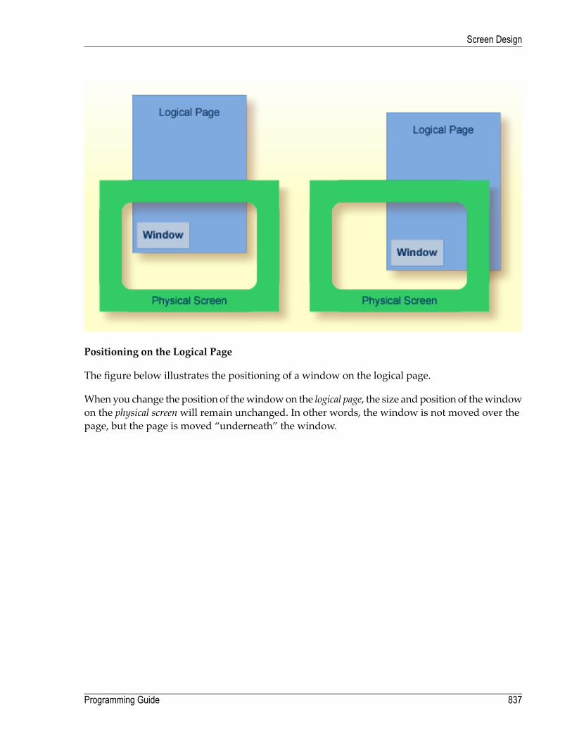
Positioning on the Logical Page
The figure below illustrates the positioning of a window on the logical page.
When you change the position of thewindowon the logical page, the size andposition of thewindowon the physical screenwill remain unchanged. In other words, the window is not moved over thepage, but the page is moved “underneath” the window.
837Programming Guide
Screen Design

DEFINE WINDOW Statement
You use the DEFINE WINDOW statement to specify the size, position and attributes of a window onthe physical screen.
A DEFINE WINDOW statement does not activate a window; this is donewith a SET WINDOW statementor with the WINDOW clause of an INPUT statement.
Various options are available with the DEFINE WINDOW statement. These are described below inthe context of the following example.
The following program defines a window on the physical screen.
** Example 'WINDX01': DEFINE WINDOW************************************************************************DEFINE DATA LOCAL1 COMMAND (A10)END-DEFINE*DEFINE WINDOW TEST
SIZE 5*25BASE 5/40TITLE 'Sample Window'CONTROL WINDOWFRAMED POSITION SYMBOL BOTTOM LEFT
Programming Guide838
Screen Design

*INPUT WINDOW='TEST' WITH TEXT 'message line'
COMMAND (AD=I'_') /'dataline 1' /'dataline 2' /'dataline 3' 'long data line'
*IF COMMAND = 'TEST2'
FETCH 'WINDX02'ELSE
IF COMMAND = '.'STOP
ELSEREINPUT 'invalid command'
END-IFEND-IFEND
Thewindow-name identifies thewindow. The namemay be up to 32 characters long. For awindowname, the same naming conventions apply as for user-defined variables. Here the name is TEST.
The window size is set with the SIZE option. Here the window is 5 lines high and 25 columns(positions) wide.
The position of the window is set by the BASE option. Here the top left-hand corner of the windowis positioned on line 5, column 40.
With the TITLE option, you can define a title that is to be displayed in thewindow frame (of course,only if you have defined a frame for the window).
With the CONTROL clause, you determine whether the PF-key lines, the message line and the stat-istics line are displayed in the window or on the full physical screen. Here CONTROL WINDOW causesthe message line to be displayed inside the window. CONTROL SCREENwould cause the lines to bedisplayed on the full physical screen outside the window. If you omit the CONTROL clause, CONTROLWINDOW applies by default.
With the FRAMED option, you define that the window is to be framed. This frame is then cursor-sensitive. Where applicable, you can page forward, backward, left or right within the window bysimply placing the cursor over the appropriate symbol (<, -, +, or >; see POSITION clause) and thenpressing Enter. In other words, you are moving the logical page underneath the window on thephysical screen. If no symbols are displayed, you can page backward and forward within thewindow by placing the cursor in the top frame line (for backward positioning) or bottom frameline (for forward positioning) and then pressing Enter.
With the POSITION clause of the FRAMED option, you define that information on the position of thewindow on the logical page is to be displayed in the frame of the window. This applies only if thelogical page is larger than thewindow; if it is not, the POSITION clausewill be ignored. The positioninformation indicates in which directions the logical page extends above, below, to the left and tothe right of the current window.
839Programming Guide
Screen Design

If the POSITION clause is omitted, POSITION SYMBOL TOP RIGHT applies by default.
POSITION SYMBOL causes the position information to be displayed in form of symbols: “More: < -+ >”. The information is displayed in the top and/or bottom frame line.
TOP/BOTTOM determines whether the position information is displayed in the top or bottom frameline.
LEFT/RIGHT determines whether the position information is displayed in the left or right part ofthe frame line.
INPUT WINDOW Statement
The INPUT WINDOW statement activates the window defined in the DEFINE WINDOW statement. Inthe example, the window TEST is activated. Note that if you wish to output data in a window (forexample, with a WRITE statement), you use the SET WINDOW statement.
When the above program is run, thewindow is displayedwith one input field COMMAND. The sessionparameter AD is used to define that the value of the field is displayed intensified and an underscoreis used as filler character.
Output of ProgramWINDX01:
Multiple Windows
You can, of course, open multiple windows. However, only one Natural window is active at anyone time, that is, themost recentwindow.Any previouswindowsmay still be visible on the screen,but are no longer active and are ignored by Natural. You may enter input only in the most recentwindow. If there is not enough space to enter input, the window size must be adjusted first.
When TEST2 is entered in the COMMAND field, the program WINDX02 is executed.
Programming Guide840
Screen Design

** Example 'WINDX02': DEFINE WINDOW************************************************************************DEFINE DATA LOCAL1 COMMAND (A10)END-DEFINE*DEFINE WINDOW TEST2
SIZE 5*30BASE 15/40TITLE 'Another Window'CONTROL SCREENFRAMED POSITION SYMBOL BOTTOM LEFT
*INPUT WINDOW='TEST2' WITH TEXT 'message line'
COMMAND (AD=I'_') /'dataline 1' /'dataline 2' /'dataline 3' 'long data line'
*IF COMMAND = 'TEST'
FETCH 'WINDX01'ELSE
IF COMMAND = '.'STOP
ELSEREINPUT 'invalid command'
END-IFEND-IFEND
A second window is opened. The other window is still visible, but it is inactive.
841Programming Guide
Screen Design

Note that for the new window the message line is now displayed at the bottom of the outputwindow and not in the window. This was defined by the CONTROL SCREEN clause in the WINDX02program.
For further details on the statements DEFINE WINDOW, INPUT WINDOW and SET WINDOW, see the cor-responding descriptions in the Statements documentation.
Standard/Dynamic Layout Maps
Standard Layout Maps
A standard layout can be defined in the map editor. This layout guarantees a uniform appearancefor all maps that reference it throughout the application.
When a map that references a standard layout is initialized, the standard layout becomes a fixedpart of the map. This means that if this standard layout is modified, all affected maps must be re-cataloged before the changes take effect.
Dynamic Layout Maps
In contrast to a standard layout, a dynamic layout does not become a fixed part of a map that refer-ences it, rather it is executed at runtime.
This means that if you define the layout map as “dynamic” on the Define Map Settings For MAPscreen in the map editor, any modifications to the layout map are also carried out on all maps thatreference it. The maps need not be re-cataloged.
For further details on layout maps, seeMap Editor in the Editors documentation.
Multilingual User Interfaces
Using Natural, you can create multilingual applications for international use.
Maps, helproutines, error messages, programs, functions, subprograms and copycodes can bedefined in up to 60 different languages (including languages with double-byte character sets).
Below is information on:
■ Language Codes■ Defining the Language of a Natural Object■ Defining the User Language■ Referencing Multilingual Objects
Programming Guide842
Screen Design

■ Programs■ Error Messages■ Edit Masks for Date and Time Fields
Language Codes
In Natural, each language has a language code (from 1 to 60). The table below is an extract from thefull table of language codes. For a complete overview, refer to the description of the system variable*LANGUAGE in the System Variables documentation.
Map Code in Object NamesLanguageLanguage Code
1English1
2German2
3French3
4Spanish4
5Italian5
6Dutch6
7Turkish7
8Danish8
9Norwegian9
AAlbanian10
BPortuguese11
The language code (left column) is the code that is contained in the system variable *LANGUAGE.This code is used by Natural internally. It is the code you use to define the user language (seeDefining the User Language below). The code you use to identify the language of a Natural objectis the map code in the right-hand column of the table.
Example:
The language code for Portuguese is “11”. The code you usewhen cataloging a PortugueseNaturalobject is “B”.
For the full table of language codes, see the system variable *LANGUAGE as described in the SystemVariables documentation.
843Programming Guide
Screen Design

Defining the Language of a Natural Object
To define the language of a Natural object (map, helproutine, program, function, subprogram orcopycode), you add the corresponding map code to the object name. Apart from the map code,the name of the object must be identical for all languages.
In the example below, amap has been created in English and in German. To identify the languagesof the maps, the map code that corresponds to the respective language has been included in themap name.
Example of Map Names for a Multilingual Application
DEMO1 = English map (map code 1)
DEMO2 = German map (map code 2)
Defining Languages with Alphabetical Map Codes
Map codes are in the range 1-9, A-Z or a-y. The alphabetical map codes require special handling.
Normally, it is not possible to catalog an object with a lower-case letter in the name - all charactersare automatically converted into capitals.
This is however necessary, if for example you wish to define an object for Kanji (Japanese) whichhas the language code 59 and the map code x.
To catalog such an object, you first set the correct language code (here 59) using the terminalcommand %L=nn, where nn is the language code.
You then catalog the object using the ampersand (&) character instead of the actual map code inthe object name. So to have a Japanese version of the map DEMO, you stow themap under the nameDEMO&.
If you now look at the list of Natural objects, you will see that the map is correctly listed as DEMOx.
Objects with language codes 1-9 and upper case A-Z can be cataloged directly without the use ofthe ampersand (&) notation.
In the example list below, you can see the three maps DEMO1, DEMO2 and DEMOx. To delete the mapDEMOx, you use the same method as when creating it, that is, you set the correct language with theterminal command %L=59 and then confirm the deletionwith the ampersand (&) notation (DEMO&).
Programming Guide844
Screen Design

Defining the User Language
You define the language to be used per user - as defined in the system variable *LANGUAGE - withthe profile parameter ULANG (which is described in the Parameter Reference) or with the terminalcommand %L=nn (where nn is the language code).
Referencing Multilingual Objects
To reference multilingual objects in a program, you use the ampersand (&) character in the nameof the object.
The program below uses the maps DEMO1 and DEMO2. The ampersand (&) character at the end ofthe map name stands for the map code and indicates that the map with the current language asdefined in the *LANGUAGE system variable is to be used.
DEFINE DATA LOCAL1 PERSONNEL VIEW OF EMPLOYEES
2 NAME (A20)2 PERSONNEL-ID (A8)
1 CAR VIEW OF VEHICLES2 REG-NUM (A15)
1 #CODE (N1)END-DEFINE*INPUT USING MAP 'DEMO&' /* <--- INVOKE MAP WITH CURRENT LANGUAGE CODE...
When this program is run, the English map (DEMO1) is displayed. This is because the current valueof *LANGUAGE is 1 = English.
845Programming Guide
Screen Design

MAP DEMO1
SAMPLE MAP
Please select a function!
1.) Employee information
2.) Vehicle information
Enter code here: _
In the example below, the language code has been switched to 2 = German with the terminalcommand %L=2.
When the program is now run, the German map (DEMO2) is displayed.
BEISPIEL-MAP
Bitte wählen Sie eine Funktion!
1.) Mitarbeiterdaten
2.) Fahrzeugdaten
Code hier eingeben: _
Programming Guide846
Screen Design
Programs
For some applications it may be useful to define multilingual programs. For example, a standardinvoicing program, might use different subprograms to handle various tax aspects, depending onthe country where the invoice is to be written.
Multilingual programs are defined with the same technique as described above for maps.
Error Messages
Using theNatural utility SYSERR, you can translateNatural errormessages into up to 60 languages,and also define your own error messages.
Which message language a user sees, depends on the *LANGUAGE system variable.
For further information on error messages, see SYSERR Utility in the Utilities documentation.
Edit Masks for Date and Time Fields
The language used for date and time fields defined with edit masks also depends on the systemvariable *LANGUAGE.
For details on edit masks, see the session parameter EM as described in the Parameter Reference.
Skill-Sensitive User Interfaces
Users with varying levels of skill may wish to have different maps (of varying detail) while usingthe same application.
If your application is not for international use by users speaking different languages, you can usethe techniques for multilingual maps to define maps of varying detail.
For example, you could define language code 1 as corresponding to the skill of the beginner, andlanguage code 2 as corresponding to the skill of the advanced user. This simple but effectivetechnique is illustrated below.
The followingmap (PERS1) includes instructions for the end user on how to select a function fromthe menu. The information is very detailed. The name of the map contains the map code 1:
847Programming Guide
Screen Design

MAP PERS1
SAMPLE MAP
Please select a function
1.) Employee information _
2.) Vehicle information _
Enter code: _
To select a function, do one of the following:
- place the cursor on the input field next to desired function and press Enter- mark the input field next to desired function with an X and press Enter- enter the desired function code (1 or 2) in the 'Enter code' field and press
Enter
The samemap, but without the detailed instructions is saved under the same name, but with mapcode 2.
MAP PERS2
SAMPLE MAP
Please select a function
1.) Employee information _
2.) Vehicle information _
Enter code: _
In the example above, the map with the detailed instructions is output, if the ULANG profile para-meter has the value 1, the map without the instructions if the value is 2. See also the descriptionof the profile parameter ULANG (in the Parameter Reference).
Programming Guide848
Screen Design
111 Dialog Design
■ Field-Sensitive Processing .............................................................................................................. 850■ Simplifying Programming ................................................................................................................ 852■ Line-Sensitive Processing ............................................................................................................... 853■ Column-Sensitive Processing ........................................................................................................... 854■ Processing Based on Function Keys .................................................................................................. 854■ Processing Based on Function-Key Names ......................................................................................... 855■ Processing Data Outside an Active Window ........................................................................................ 856■ Copying Data from a Screen ............................................................................................................ 859■ Statements REINPUT/REINPUT FULL .............................................................................................. 862■ Object-Oriented Processing - The Natural Command Processor .............................................................. 863
849

This chapter tells you howyou can design character-based user interfaces thatmake user interactionwith the application simple and flexible.
Note: For information on the design of graphical user interfaces (GUI), refer to Introductionto Event-Driven Programming.
Field-Sensitive Processing
*CURS-FIELD and POS(field-name)
Using the system variable *CURS-FIELD together with the system function POS(field-name), youcan define processing based on the fieldwhere the cursor is positioned at the time the user pressesEnter.
*CURS-FIELD contains the internal identification of the fieldwhere the cursor is currently positioned;it cannot be used by itself, but only in conjunction with POS(field-name).
You can use *CURS-FIELD and POS(field-name), for example, to enable a user to select a functionsimply by placing the cursor on a specific field and pressing Enter.
The example below illustrates such an application:
DEFINE DATA LOCAL1 #EMP (A1)1 #CAR (A1)1 #CODE (N1)END-DEFINE*INPUT USING MAP 'CURS'*DECIDE FOR FIRST CONDITION
WHEN *CURS-FIELD = POS(#EMP) OR #EMP = 'X' OR #CODE = 1FETCH 'LISTEMP'
WHEN *CURS-FIELD = POS(#CAR) OR #CAR = 'X' OR #CODE = 2FETCH 'LISTCAR'
WHEN NONEREINPUT 'PLEASE MAKE A VALID SELECTION'
END-DECIDEEND
And the result:
Programming Guide850
Dialog Design
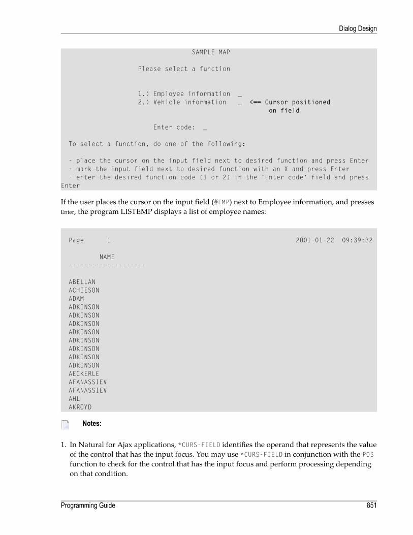
SAMPLE MAP
Please select a function
1.) Employee information _2.) Vehicle information _ <== Cursor positioned
on field
Enter code: _
To select a function, do one of the following:
- place the cursor on the input field next to desired function and press Enter- mark the input field next to desired function with an X and press Enter- enter the desired function code (1 or 2) in the 'Enter code' field and press
Enter
If the user places the cursor on the input field (#EMP) next to Employee information, and pressesEnter, the program LISTEMP displays a list of employee names:
Page 1 2001-01-22 09:39:32
NAME--------------------
ABELLANACHIESONADAMADKINSONADKINSONADKINSONADKINSONADKINSONADKINSONADKINSONADKINSONAECKERLEAFANASSIEVAFANASSIEVAHLAKROYD
Notes:
1. In Natural for Ajax applications, *CURS-FIELD identifies the operand that represents the valueof the control that has the input focus. You may use *CURS-FIELD in conjunction with the POSfunction to check for the control that has the input focus and perform processing dependingon that condition.
851Programming Guide
Dialog Design

2. The values of *CURS-FIELD and POS(field-name) serve for internal identification of the fieldsonly. They cannot be used for arithmetical operations.
Simplifying Programming
System Function POS
The Natural system function POS(field-name) contains the internal identification of the fieldwhose name is specified with the system function.
POS(field-name)may be used to identify a specific field, regardless of its position in a map. Thismeans that the sequence and number of fields in a map may be changed, but POS(field-name)will still uniquely identify the same field. With this, for example, you need only a single REINPUTstatement to make the field to be MARKed dependent on the program logic.
Note: The value POS(field-name) serves for internal identification of the fields only. Itcannot be used for arithmetical operations.
Example:
...DECIDE ON FIRST VALUE OF ...
VALUE ...COMPUTE #FIELDX = POS(FIELD1)
VALUE ...COMPUTE #FIELDX = POS(FIELD2)
...END-DECIDE...REINPUT ... MARK #FIELDX...
Full details on *CURS-FIELD and POS(field-name) are described in the System Variables and SystemFunctions documention.
Programming Guide852
Dialog Design

Line-Sensitive Processing
System Variable *CURS-LINE
Using the system variable *CURS-LINE, you can make processing dependent on the line where thecursor is positioned at the time the user presses Enter.
Using this variable, you can make user-friendly menus. With the appropriate programming, theusermerely has to place the cursor on the line of the desiredmenu option and press Enter to executethe option.
The cursor position is definedwithin the current activewindow, regardless of its physical placementon the screen.
Note: The message line, function-key lines and statistics line/infoline are not counted asdata lines on the screen.
The example below demonstrates line-sensitive processing using the *CURS-LINE system variable.When the user presses Enter on the map, the program checks if the cursor is positioned on line 8of the screen which contains the option Employee information. If this is the case, the programthat lists the names of employees LISTEMP is executed.
DEFINE DATA LOCAL1 #EMP (A1)1 #CAR (A1)1 #CODE (N1)END-DEFINE*INPUT USING MAP 'CURS'*DECIDE FOR FIRST CONDITION
WHEN *CURS-LINE = 8FETCH 'LISTEMP'
WHEN NONEREINPUT 'PLACE CURSOR ON LINE OF OPTION YOU WISH TO SELECT'
END-DECIDEEND
Output:
853Programming Guide
Dialog Design
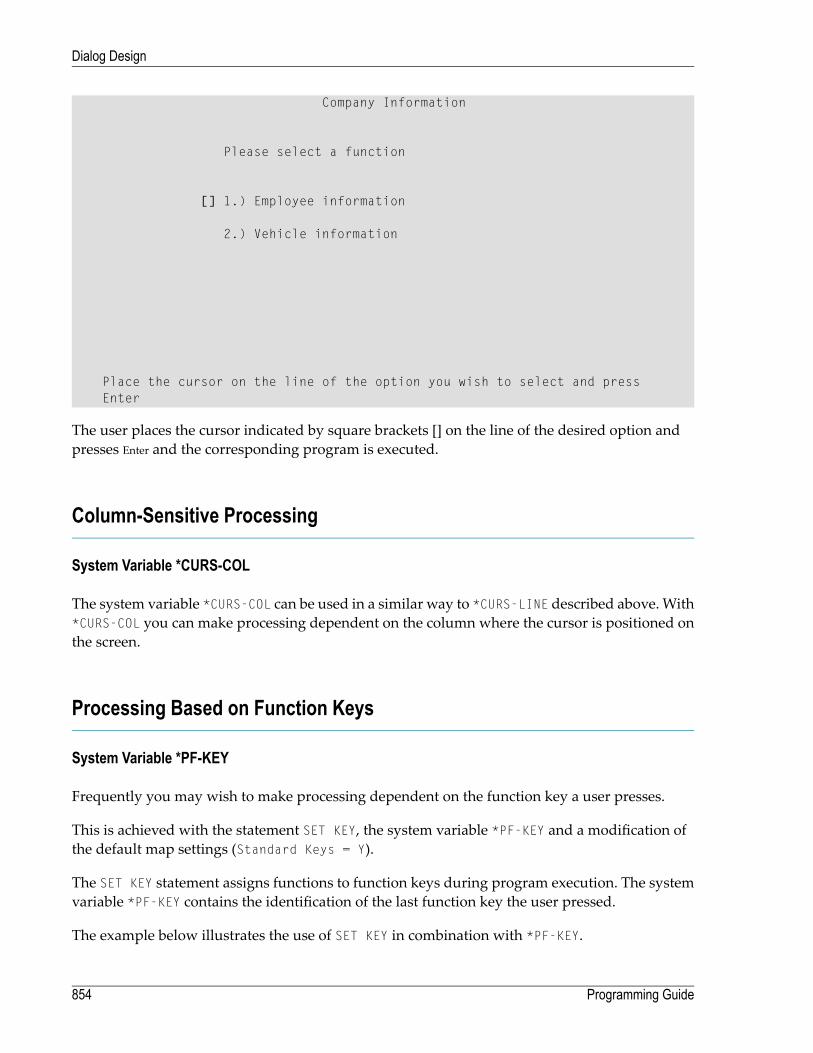
Company Information
Please select a function
[] 1.) Employee information
2.) Vehicle information
Place the cursor on the line of the option you wish to select and pressEnter
The user places the cursor indicated by square brackets [] on the line of the desired option andpresses Enter and the corresponding program is executed.
Column-Sensitive Processing
System Variable *CURS-COL
The system variable *CURS-COL can be used in a similar way to *CURS-LINE described above. With*CURS-COL you can make processing dependent on the column where the cursor is positioned onthe screen.
Processing Based on Function Keys
System Variable *PF-KEY
Frequently you may wish to make processing dependent on the function key a user presses.
This is achieved with the statement SET KEY, the system variable *PF-KEY and a modification ofthe default map settings (Standard Keys = Y).
The SET KEY statement assigns functions to function keys during program execution. The systemvariable *PF-KEY contains the identification of the last function key the user pressed.
The example below illustrates the use of SET KEY in combination with *PF-KEY.
Programming Guide854
Dialog Design
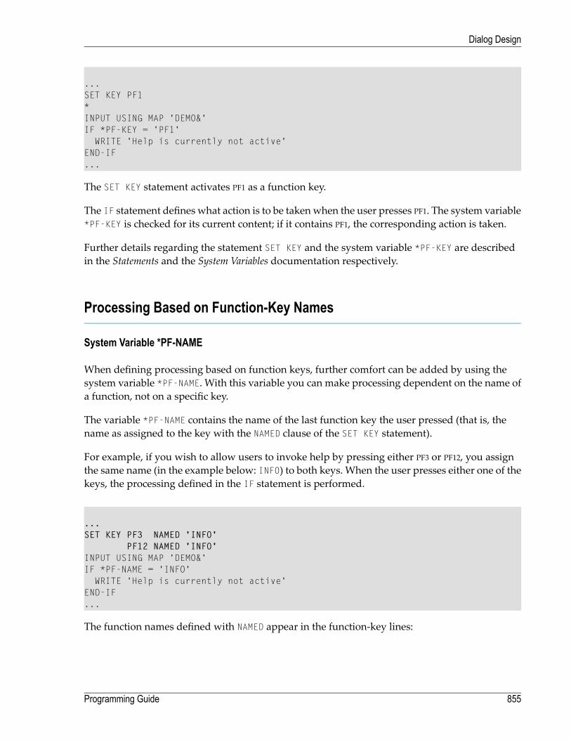
...SET KEY PF1*INPUT USING MAP 'DEMO&'IF *PF-KEY = 'PF1'
WRITE 'Help is currently not active'END-IF...
The SET KEY statement activates PF1 as a function key.
The IF statement defines what action is to be taken when the user presses PF1. The system variable*PF-KEY is checked for its current content; if it contains PF1, the corresponding action is taken.
Further details regarding the statement SET KEY and the system variable *PF-KEY are describedin the Statements and the System Variables documentation respectively.
Processing Based on Function-Key Names
System Variable *PF-NAME
When defining processing based on function keys, further comfort can be added by using thesystem variable *PF-NAME. With this variable you can make processing dependent on the name ofa function, not on a specific key.
The variable *PF-NAME contains the name of the last function key the user pressed (that is, thename as assigned to the key with the NAMED clause of the SET KEY statement).
For example, if you wish to allow users to invoke help by pressing either PF3 or PF12, you assignthe same name (in the example below: INFO) to both keys. When the user presses either one of thekeys, the processing defined in the IF statement is performed.
...SET KEY PF3 NAMED 'INFO'
PF12 NAMED 'INFO'INPUT USING MAP 'DEMO&'IF *PF-NAME = 'INFO'
WRITE 'Help is currently not active'END-IF...
The function names defined with NAMED appear in the function-key lines:
855Programming Guide
Dialog Design
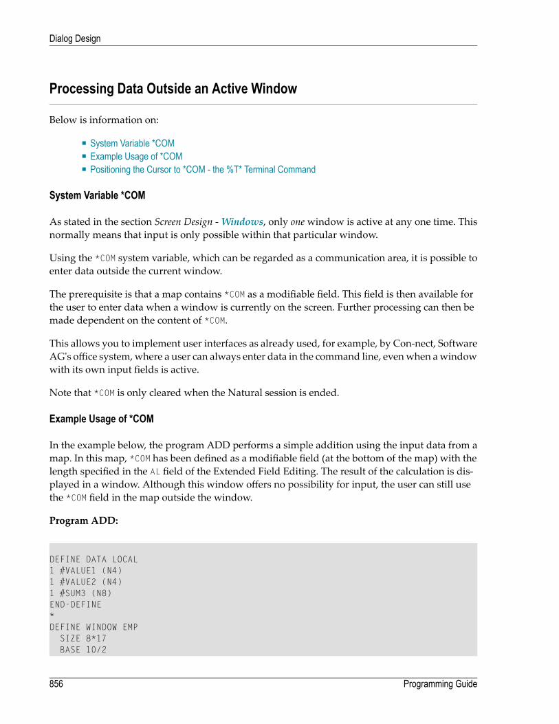
Processing Data Outside an Active Window
Below is information on:
■ System Variable *COM■ Example Usage of *COM■ Positioning the Cursor to *COM - the %T* Terminal Command
System Variable *COM
As stated in the section Screen Design -Windows, only onewindow is active at any one time. Thisnormally means that input is only possible within that particular window.
Using the *COM system variable, which can be regarded as a communication area, it is possible toenter data outside the current window.
The prerequisite is that a map contains *COM as a modifiable field. This field is then available forthe user to enter data when a window is currently on the screen. Further processing can then bemade dependent on the content of *COM.
This allows you to implement user interfaces as already used, for example, by Con-nect, SoftwareAG's office system,where a user can always enter data in the command line, evenwhen awindowwith its own input fields is active.
Note that *COM is only cleared when the Natural session is ended.
Example Usage of *COM
In the example below, the program ADD performs a simple addition using the input data from amap. In this map, *COM has been defined as a modifiable field (at the bottom of the map) with thelength specified in the AL field of the Extended Field Editing. The result of the calculation is dis-played in a window. Although this window offers no possibility for input, the user can still usethe *COM field in the map outside the window.
Program ADD:
DEFINE DATA LOCAL1 #VALUE1 (N4)1 #VALUE2 (N4)1 #SUM3 (N8)END-DEFINE*DEFINE WINDOW EMP
SIZE 8*17BASE 10/2
Programming Guide856
Dialog Design

TITLE 'Total of Add'CONTROL SCREENFRAMED POSITION SYMBOL BOT LEFT
*INPUT USING MAP 'WINDOW'*COMPUTE #SUM3 = #VALUE1 + #VALUE2*SET WINDOW 'EMP'INPUT (AD=O) / 'Value 1 +' /
'Value 2 =' //' ' #SUM3
*IF *COM = 'M'
FETCH 'MULTIPLY' #VALUE1 #VALUE2END-IFEND
Output of Program ADD:
Map to Demonstrate Windows with *COM
CALCULATOR
Enter values you wish to calculate
Value 1: 12__Value 2: 12__
+-Total of Add-+! !! Value 1 + !! Value 2 = !! !! 24 !! !+--------------+
Next line is input field (*COM) for input outside the window:
In this example, by entering the value M, the user initiates amultiplication function; the two valuesfrom the input map are multiplied and the result is displayed in a second window:
857Programming Guide
Dialog Design

Map to Demonstrate Windows with *COM
CALCULATOR
Enter values you wish to calculate
Value 1: 12__Value 2: 12__
+-Total of Add-+ +--------------+! ! ! !! Value 1 + ! ! Value 1 x !! Value 2 = ! ! Value 2 = !! ! ! !! 24 ! ! 144 !! ! ! !+--------------+ +--------------+
Next line is input field (*COM) for input outside the window:M
Positioning the Cursor to *COM - the %T* Terminal Command
Normally, when a window is active and the window contains no input fields (AD=M or AD=A), thecursor is placed in the top left corner of the window.
With the terminal command %T*, you can position the cursor to a *COM system variable outsidethe window when the active window contains no input fields.
By using %T* again, you can switch back to standard cursor placement.
Example:
...INPUT USING MAP 'WINDOW'*COMPUTE #SUM3 = #VALUE1 + #VALUE2*SET CONTROL 'T*'SET WINDOW 'EMP'INPUT (AD=O) / 'Value 1 +' /
'Value 2 =' //' ' #SUM3
...
Programming Guide858
Dialog Design

Copying Data from a Screen
Below is information on:
■ Terminal Commands %CS and %CC■ Selecting a Line from Report Output for Further Processing
Terminal Commands %CS and %CC
With these terminal commands, you can copy parts of a screen into the Natural stack (%CS) or intothe system variable *COM (%CC). The protected data from a specific screen line are copied field byfield.
The full options of these terminal commands are described in the Terminal Commands documenta-tion.
Once copied to the stack or *COM, the data are available for further processing. Using these com-mands, you can make user-friendly interfaces as in the example below.
Selecting a Line from Report Output for Further Processing
In the following example, the program COM1 lists all employee names from Abellan to Alestia.
Program COM1:
DEFINE DATA LOCAL1 EMP VIEW OF EMPLOYEES
2 NAME(A20)2 MIDDLE-NAME (A20)2 PERSONNEL-ID (A8)
END-DEFINE*READ EMP BY NAME STARTING FROM 'ABELLAN' THRU 'ALESTIA'
DISPLAY NAMEEND-READFETCH 'COM2'END
Output of Program COM1:
859Programming Guide
Dialog Design
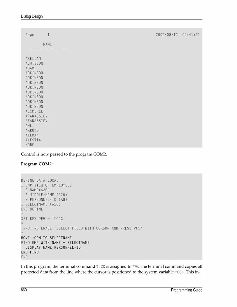
Page 1 2006-08-12 09:41:21
NAME--------------------
ABELLANACHIESONADAMADKINSONADKINSONADKINSONADKINSONADKINSONADKINSONADKINSONADKINSONAECKERLEAFANASSIEVAFANASSIEVAHLAKROYDALEMANALESTIAMORE
Control is now passed to the program COM2.
Program COM2:
DEFINE DATA LOCAL1 EMP VIEW OF EMPLOYEES
2 NAME(A20)2 MIDDLE-NAME (A20)2 PERSONNEL-ID (A8)
1 SELECTNAME (A20)END-DEFINE*SET KEY PF5 = '%CCC'*INPUT NO ERASE 'SELECT FIELD WITH CURSOR AND PRESS PF5'*MOVE *COM TO SELECTNAMEFIND EMP WITH NAME = SELECTNAME
DISPLAY NAME PERSONNEL-IDEND-FINDEND
In this program, the terminal command %CCC is assigned to PF5. The terminal command copies allprotected data from the line where the cursor is positioned to the system variable *COM. This in-
Programming Guide860
Dialog Design
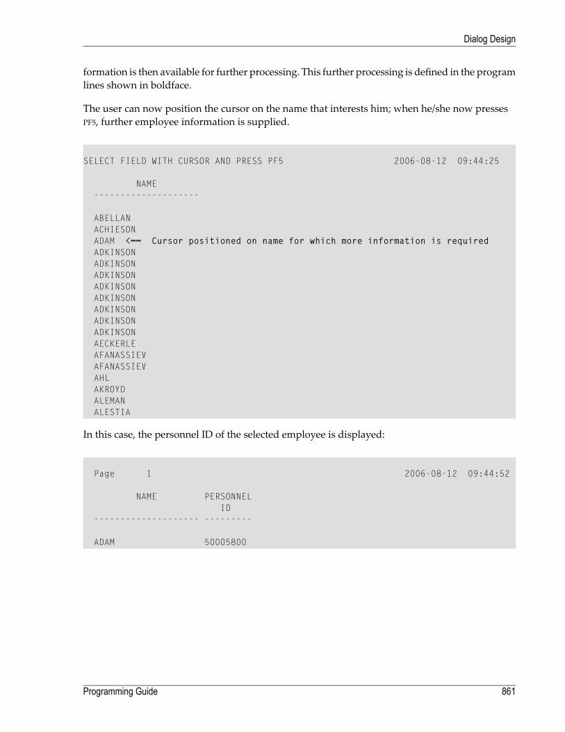
formation is then available for further processing. This further processing is defined in the programlines shown in boldface.
The user can now position the cursor on the name that interests him; when he/she now pressesPF5, further employee information is supplied.
SELECT FIELD WITH CURSOR AND PRESS PF5 2006-08-12 09:44:25
NAME--------------------
ABELLANACHIESONADAM <== Cursor positioned on name for which more information is requiredADKINSONADKINSONADKINSONADKINSONADKINSONADKINSONADKINSONADKINSONAECKERLEAFANASSIEVAFANASSIEVAHLAKROYDALEMANALESTIA
In this case, the personnel ID of the selected employee is displayed:
Page 1 2006-08-12 09:44:52
NAME PERSONNELID
-------------------- ---------
ADAM 50005800
861Programming Guide
Dialog Design

Statements REINPUT/REINPUT FULL
If you wish to return to and re-execute an INPUT statement, you use the REINPUT statement. It isgenerally used to display amessage indicating that the data input as a result of the previous INPUTstatement were invalid.
If you specify the FULL option in a REINPUT statement, the corresponding INPUT statement will bere-executed fully:
■ With an ordinary REINPUT statement (without FULL option), the contents of variables that werechanged between the INPUT and REINPUT statement will not be displayed; that is, all variableson the screenwill show the contents they hadwhen the INPUT statementwas originally executed.
■ With a REINPUT FULL statement, all changes that have been made after the initial execution ofthe INPUT statement will be applied to the INPUT statement when it is re-executed; that is, allvariables on the screen contain the values they had when the REINPUT statement was executed.
■ If youwish to position the cursor to a specified field, you can use the MARK option, and to positionto a particular position within a specified field, you use the MARK POSITION option.
The example below illustrates the use of REINPUT FULLwith MARK POSITION.
DEFINE DATA LOCAL1 #A (A10)1 #B (N4)1 #C (N4)END-DEFINE*INPUT (AD=M) #A #B #CIF #A = ' '
COMPUTE #B = #B + #CRESET #CREINPUT FULL 'Enter a value' MARK POSITION 5 IN *#A
END-IFEND
The user enters 3 in field #B and 3 in field #C and presses Enter.
#A #B 3 #C 3
The program requires field #A to be non-blank. The REINPUT FULL statement with MARK POSITION5 IN *#A returns the input screen; the now modified variable #B contains the value 6 (after theCOMPUTE calculation has been performed). The cursor is positioned to the 5th position in field #Aready for new input.
Programming Guide862
Dialog Design

Enter name of field#A _ #B 6 #C 0
Enter a value
This is the screen that would be returned by the same statement, without the FULL option. Notethat the variables #B and #C have been reset to their status at the time of execution of the INPUTstatement (each field contains the value 3).
#A _ #B 3 #C 3
Object-Oriented Processing - The Natural Command Processor
The Natural Command Processor is used to define and control navigation within an application.It consists of two parts: The development part and the run-time part.
■ The development part is the utility SYSNCP. With this utility, you define commands and theactions to be performed in response to the execution of these commands. From your definitions,SYSNCPgenerates decision tableswhichdeterminewhat happenswhen auser enters a command.
■ The run-time part is the statement PROCESS COMMAND. This statement is used to invoke theCommand Processor within a Natural program. In the statement you specify the name of theSYSNCP table to be used to handle the data input by a user at that point.
For further information regarding the Natural Command Processor, see SYSNCP Utility in theUtilities documentation and the statement PROCESS COMMAND as described in the Statements docu-mentation.
863Programming Guide
Dialog Design

864

XIII Natural Native Interface
This part covers the following topics:
Introduction
Interface Library and Location
Interface Versioning
Interface Access
Interface Instances and Natural Sessions
Interface Functions
Parameter Description Structure
Natural Data Types
Flags
Return Codes
Natural Exception Structure
Interface Usage
Threading Issues
865

866

112 Introduction
The Natural Native Interface enables an application to execute Natural code in its own processcontext through function calls according to the C calling convention. The interface consists of aDLL that contains a set of interface functions. These functions include initialization and uninitial-ization of a Natural session, logging on to a specific Natural library and execution of individualNatural modules. The calling application loads the interface library dynamically with operatingsystem calls and then locates and calls the interface functions.
An example C program nnisample.c that shows the usage of the interface is contained in%NAT-DIR%\%NATVERS%\samples\sysexnni.
The Natural modules called by the C program nnisample.c are contained in the Natural librarySYSEXNNI.
867

868

113 Interface Library and Location
The interface consists of aDLL that exports a set of functions. The individual functions are describedin Interface Functions. The interface DLL is called natni.dll and is contained in the Natural bindirectory.
When executing a program that uses the Natural Native Interface, the Natural bin directory mustbe defined in the environment variable PATH, so that the calling program can locate the interfacelibrary and all dependent libraries.
869

870

114 Interface Versioning
The Natural Native Interface might change in future versions of Natural. Natural versions thatprovide a modified interface will support previous interface versions in parallel, until a point intime that is determined by Software AG and is announced in time. To access an instance of a spe-cific version of the interface, the application calls the function nni_get_interface. The applicationpasses the required interface version number to the function and receives a structurewith functionpointers in return. The application may also request the most recent interface version, withoutspecifying the interface version explicitly.
871

872
115 Interface Access
In order to access the interface, an application loads the interface library using a platformdependentsystem call.
Then the application locates the address of the function nni_get_interface, again using a platformdependent system call. Once the application has located the central function nni_get_interface,it requests an instance of the interface by calling the function nni_get_interface and specifyingthe desired interface version. The resulting structure contains the interface function pointers.
After having finished using the interface functions, the application unloads the interface libraryusing a platform dependent system call.
The sample program nnisample.c demonstrates the interface. Also the platform dependent mech-anismof loading the interface library and the access to the function nni_get_interface is illustratedby this sample program.
873

874
116 Interface Instances and Natural Sessions
The function nni_get_interface returns a pointer to an instance of the Natural Native Interface.One interface instance can host one Natural session at a time. An application initializes a Naturalsession by calling the function nni_initialize on a given interface instance. It uninitializes theNatural session by calling nni_uninitialize on that interface instance. After that it can initializea new Natural session on the same interface instance.
It is implementation dependent if multiple interface instances and thus multiple Natural sessionscan bemaintained per process or per thread. In the current implementation ofNatural onWindows,UNIX and OpenVMS, one process can host one Natural session at a time. Consequently, everycall to nni_get_interface in one process yields the same interface instance. However, this uniqueinterface instance can be used alternating by several concurrently running threads. The threadsynchronization is implicitly performed by the interface functions themselves. Optionally it canbe performed by the application explicitly. The interface provides the required synchronizationfunctions nni_enter, nni_try_enter and nni_leave.
875

876

117 Interface Functions
■ nni_get_interface ........................................................................................................................... 879■ nni_free_interface .......................................................................................................................... 880■ nni_initialize .................................................................................................................................. 880■ nni_is_initialized ............................................................................................................................ 882■ nni_uninitialize .............................................................................................................................. 882■ nni_enter ..................................................................................................................................... 883■ nni_try_enter ................................................................................................................................ 883■ nni_leave ..................................................................................................................................... 884■ nni_logon ..................................................................................................................................... 885■ nni_logoff ..................................................................................................................................... 885■ nni_callnat .................................................................................................................................... 886■ nni_create_object .......................................................................................................................... 887■ nni_send_method .......................................................................................................................... 888■ nni_get_property ........................................................................................................................... 890■ nni_set_property ............................................................................................................................ 891■ nni_delete_object .......................................................................................................................... 893■ nni_create_parm ........................................................................................................................... 894■ nni_create_module_parm ................................................................................................................ 895■ nni_create_method_parm ................................................................................................................ 896■ nni_create_prop_parm .................................................................................................................... 897■ nni_parm_count ............................................................................................................................ 898■ nni_init_parm_s ............................................................................................................................. 898■ nni_init_parm_sa ........................................................................................................................... 899■ nni_init_parm_d ............................................................................................................................. 901■ nni_init_parm_da ........................................................................................................................... 901■ nni_get_parm_info ......................................................................................................................... 903■ nni_get_parm ................................................................................................................................ 903■ nni_get_parm_array ....................................................................................................................... 905■ nni_get_parm_array_length ............................................................................................................. 906■ nni_put_parm ................................................................................................................................ 907■ nni_put_parm_array ....................................................................................................................... 908■ nni_resize_parm_array ................................................................................................................... 909
877

■ nni_delete_parm ............................................................................................................................ 910■ nni_from_string ............................................................................................................................. 911■ nni_to_string ................................................................................................................................. 912
Programming Guide878
Interface Functions

nni_get_interface
Syntax
int nni_get_interface( int iVersion, void** ppnni_func );
The function returns an instance of the Natural Native Interface.
An application calls this function after having retrieved and loaded the interface library withplatformdepending system calls. The function returns a pointer to a structure that contains functionpointers to the individual interface functions. The functions returned in the structure may differbetween interface versions.
Instead of a specific interface version, the caller can also specify the constant NNI_VERSION_CURR,which always refers to the most recent interface version. The interface version number belongingto a given Natural version is defined in the header file natni.h that is delivered with that version.In Natural Version n.n, the interface version number is defined as NNI_VERSION_nn.NNI_VERSION_CURR is also defined as NNI_VERSION_nn. If the Natural version against which thefunction is called does not support the requested interface version, the error code NNI_RCVERSION_ERROR is returned. Otherwise the return code is NNI_RC_OK.
The pointer returned by the function represents one instance of the interface. In order to use thisinterface instance, the application holds on to that pointer and passes it to subsequent interfacecalls.
Usually the application will subsequently initialize a Natural session by calling nni_initializeon the given instance. After the application has finished using that Natural session, it callsnni_uninitialize on that instance. After that it can initialize a different Natural session on thesame interface instance. After the application has finished using the interface instance entirely, itcalls nni_free_interface on that instance.
Parameters
MeaningParameter
Interface version number. (NNI_VERSION_nn or NNI_VERSION_CURR).iVersion
Points to an NNI interface instance on return.ppnni_func
Return Codes
The meaning of the return codes is explained in the section Return Codes.
879Programming Guide
Interface Functions

RemarkReturn Code
NNI_RC_OK
NNI_RC_PARM_ERROR
NNI_RC_VERSION_ERROR
nni_free_interface
Syntax
int nni_free_interface(void* pnni_func);
An application calls this function after it has finished using the interface instance and has unini-tialized the Natural session it hosts. The function frees the resources occupied by that interfaceinstance.
Parameters
MeaningParameter
Pointer to an NNI interface instance.pnni_func
Return Codes
The meaning of the return codes is explained in the section Return Codes.
RemarkReturn Code
NNI_RC_OK
nni_initialize
Syntax
int nni_initialize(void* pnni_func, const char* szCmdLine, void*, void*);
The function initializes a Natural session with a given command line. The syntax and semanticsof the command line is the same as when Natural is started interactively. If a Natural session hasalready been initialized on the given interface instance, that session is implicitly uninitialized beforethe new session is initialized.
The command line must be specified in the way that the Natural initialization can be completedwithout user interaction. Thismeans especially that if a program is passed on the stack or a startup
Programming Guide880
Interface Functions

program is specified, that programmust not perform an INPUT statement that is not satisfied fromthe stack. Otherwise the subsequent behavior of the Natural session is undetermined.
The Natural session is initialized as batch session and in server mode. This means that the usageof certain statements and commands in the executedNaturalmodules is restricted. These restrictionsand error conditions are the same as documented in the section Using Statements and Commandsin a NaturalX Server Environment of the Operations documentation.
When initalizing aNatural session underNatural Security, the command linemust contain a LOGONcommand to a freely chosen default library under which the sessionwill be started, and an appro-priate user ID and password.
Example:
int iRes =pnni_func->nni_initialize( pnni_func, "STACK=(LOGON,MYLIB,MYUSER,MYPASS)", 0, 0);
If the application later calls nni_logon to a different librarywith a different user ID and afterwardscalls nni_logoff, theNatural sessionwill be reset to the library and user ID thatwas passed duringnni_initialize.
Parameters
MeaningParameter
Pointer to an NNI interface instance.pnni_func
Natural command line. May be a null pointer.szCmdLine
For future use. Must be a null pointer.void*
For future use. Must be a null pointer.void*
Return Codes
The meaning of the return codes is explained in the section Return Codes.
RemarkReturn Code
NNI_RC_OK
NNI_RC_PARM_ERROR
Natural startup error. The real Natural startup error number asdocumented in Natural Startup Errors (which is part of the Operationsdocumentation) can be determined by the following calculation:
startup-error-nr = - (rc - NNI_RC_SERR_OFFSET)
rc, where rc <NNI_RC_SERR_OFFSET
Warnings that occur during session initialization are ignored.
Natural error number.> 0
881Programming Guide
Interface Functions
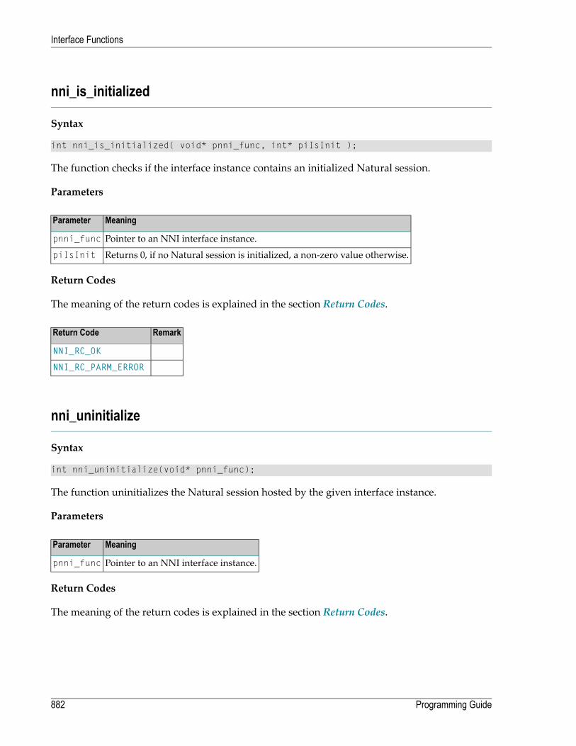
nni_is_initialized
Syntax
int nni_is_initialized( void* pnni_func, int* piIsInit );
The function checks if the interface instance contains an initialized Natural session.
Parameters
MeaningParameter
Pointer to an NNI interface instance.pnni_func
Returns 0, if no Natural session is initialized, a non-zero value otherwise.piIsInit
Return Codes
The meaning of the return codes is explained in the section Return Codes.
RemarkReturn Code
NNI_RC_OK
NNI_RC_PARM_ERROR
nni_uninitialize
Syntax
int nni_uninitialize(void* pnni_func);
The function uninitializes the Natural session hosted by the given interface instance.
Parameters
MeaningParameter
Pointer to an NNI interface instance.pnni_func
Return Codes
The meaning of the return codes is explained in the section Return Codes.
Programming Guide882
Interface Functions

RemarkReturn Code
NNI_RC_OK
nni_enter
Syntax
int nni_enter(void* pnni_func);
The function lets the current thread wait for exclusive access to the interface instance and theNatural session it hosts. A thread calls this function if it wants to issue a series of interface callsthatmay not be interrupted by other threads. The thread releases the eclusive access to the interfaceinstance by calling nni_leave.
Parameters
MeaningParameter
Pointer to an NNI interface instance.pnni_func
Return Codes
The meaning of the return codes is explained in the section Return Codes.
RemarkReturn Code
NNI_RC_OK
nni_try_enter
Syntax
int nni_try_enter(void* pnni_func);
The function behaves like nni_enter except that it does not block the thread and instead alwaysreturns immediately. If a different thread already has exclusive access to the interface instance,the function returns NNI_RC_LOCKED.
883Programming Guide
Interface Functions

Parameters
MeaningParameter
Pointer to an NNI interface instance.pnni_func
Return Codes
The meaning of the return codes is explained in the section Return Codes.
RemarkReturn Code
NNI_RC_OK
NNI_RC_LOCKED
nni_leave
Syntax
int nni_leave(void* pnni_func);
The function releases exclusive access to the interface instance and allows other threads to accessthat instance and the Natural session it hosts.
Parameters
MeaningParameter
Pointer to an NNI interface instance.pnni_func
Return Codes
The meaning of the return codes is explained in the section Return Codes.
RemarkReturn Code
NNI_RC_OK
Programming Guide884
Interface Functions

nni_logon
Syntax
int nni_logon(void* pnni_func, const char* szLibrary, const char* szUser, const ↩char* szPassword);
The function performs a LOGON to the specified Natural library.
Parameters
MeaningParameter
Pointer to an NNI interface instance.pnni_func
Name of the Natural library.szLibrary
Name of the Natural user. May be a null pointer, if the Natural session is not running underNatural Security or if AUTO=ONwas used during initialization.
szUser
Password of that user. May be a null pointer, if the Natural session is not running underNatural Security or if AUTO=ONwas used during initialization..
szPassword
Return Codes
The meaning of the return codes is explained in the section Return Codes.
RemarkReturn Code
NNI_RC_OK
NNI_RC_NOT_INIT
NNI_RC_PARM_ERROR
Natural error number.> 0
nni_logoff
Syntax
int nni_logoff(void* pnni_func);
The function performs a LOGOFF from the current Natural library. This corresponds to a LOGON tothe previously active library and user ID.
885Programming Guide
Interface Functions

Parameters
MeaningParameter
Pointer to an NNI interface instance.pnni_func
Return Codes
The meaning of the return codes is explained in the section Return Codes.
RemarkReturn Code
NNI_RC_OK
NNI_RC_NOT_INIT
NNI_RC_PARM_ERROR
Natural error number.> 0
nni_callnat
Syntax
int nni_callnat(void* pnni_func, const char* szName, int iParm, struct ↩parameter_description* rgDesc, struct natural_exception* pExcep);
The function calls a Natural subprogram.
The function receives its parameters as an array of parameter_description structures. The callercreates these structures using NNI functions in the following way:
■ Use one the functions create_parm or create_module_parm to create an appropriate parameterset for the subprogram.
■ If you have used create_parm, use the functions init_parm_* to initialize each parameter tothe appropriate Natural data format. If you have used create_module_parm, the parameters arealready initialized to the appropriate Natural data format.
■ Assign a value to each parameter, using one the functions nni_put_parm or nni_put_parm_array.■ Call nni_get_parm on each parameter in the set. This fills the parameter_description structures.■ Pass the array of parameter_description structures to the function nni_callnat.■ After the call has been executed, extract the modified parameter values from the parameter setusing the function nni_get_parm or nni_get_parm_array.
Programming Guide886
Interface Functions

Parameters
MeaningParameter
Pointer to an NNI interface instance.pnni_func
Name of the Natural subprogram.szName
Number of parameters. Indicates the number of occurrences of the array rgDesc.iParm
An array of parm_description structures containing the parameters for the subprogram. Ifthe subprogram does not expect parameters, the caller passes a null pointer.
rgDesc
Pointer to a natural_exception structure. If a Natural error occurs during execution of thesubprogram,this structure is filled with Natural error information. The caller may specify anull pointer. In this case no extended error information is returned.
pExcep
Return Codes
The meaning of the return codes is explained in the section Return Codes.
RemarkReturn Code
NNI_RC_OK
NNI_RC_NOT_INIT
NNI_RC_PARM_ERROR
NNI_RC_NO_MEMORY
Natural error number.> 0
nni_create_object
Syntax
int nni_create_object(void* pnni_func, const char* szName, int iParm, struct ↩parameter_description* rgDesc, struct natural_exception* pExcep); ↩
Creates a Natural object (an instance of a Natural class).
The function receives its parameters as a one-element array of parameter_description structures.The caller creates the structures using NNI functions in the following way:
■ Use the function nni_create_parm to create parameter set with one element.■ Use the function nni_init_parm_s to initialize the parameter with the type HANDLE OF OBJECT.■ Call nni_get_parm_info on this parameter. This fills the parameter_description structure.■ Pass the parameter_description structure to the function nni_create_object.■ After the call has been executed, extract the modified parameter value from the parameter setusing one the function nni_get_parm.
887Programming Guide
Interface Functions

The parameters passed in rgDesc have the following meaning:
■ The first (and only) parameter must be initialized with the data type HANDLE OF OBJECT andcontains on return the Natural object handle of the newly created object.
Parameters
MeaningParameter
Pointer to an NNI interface instance.pnni_func
Name of the class.szName
Number of parameters. Indicates the number of occurrences of the array rgDesc.iParm
An array of parm_description structures containing the parameters for the object creation.The caller always passes one parameter, which will contain the object handle on return.
rgDesc
Pointer to a natural_exception structure. If a Natural error occurs during object creation,this structure is filled with Natural error information. The caller may specify a null pointer.In this case no extended exception information is returned.
pExcep
Return Codes
The meaning of the return codes is explained in the section Return Codes.
RemarkReturn Code
NNI_RC_OK
NNI_RC_NOT_INIT
NNI_RC_PARM_ERROR
NNI_RC_NO_MEMORY
Natural error number.> 0
nni_send_method
Syntax
int nni_send_method(void* pnni_func, const char* szName, int iParm, struct ↩parameter_description* rgDesc, struct natural_exception* pExcep);
Sends a method call to a Natural object (an instance of a Natural class).
The function receives its parameters as an array of parameter_description structures. The callercreates these structures using NNI functions in the following way:
■ Use the function nni_create_parm or nni_create_method_parm to create amatching parameterset.
Programming Guide888
Interface Functions

■ If you have used create_parm, use the functions init_parm_* to initialize each parameter tothe appropriateNatural data format. If you have used nni_create_method_parm, the parametersare already initialized to the appropriate Natural data format.
■ Assign a value to each parameter using one the functions nni_put_parm or nni_put_parm_array.■ Call nni_get_parm_info on each parameter in the set. This fills the parameter_descriptionstructures.
■ Pass the array of parameter_description structures to the function nni_send_method.■ After the call has been executed, extract the modified parameter values from the parameter setusing one of the nni_get_parm functions.
The parameters passed in rgDesc have the following meaning:
■ The first parameter contains the object handle.■ The second parameter must be initialized to the data type of the method return value. If themethod does not have a return value, the second parameter remains not initialized. On returnfrom the method call, this parameter contains the return value of the method.
■ The remaining parameters are the method parameters.
Parameters
MeaningParameter
Pointer to an NNI interface instance.pnni_func
Name of the method.szName
Number of parameters. Indicates the number of occurrences of the array rgDesc. This is always2 + the number of method parameters.
iParm
An array of parm_description structures containing the parameters for the method. If themethod does not expect parameters, the caller still passes two parameters, the first for theobject handle and the second for the return value.
rgDesc
Pointer to a natural_exception structure. If a Natural error occurs during execution of themethod, this structure is filled with Natural error information. The caller may specify a nullpointer. In this case no extended exception information is returned.
pExcep
Return Codes
The meaning of the return codes is explained in the section Return Codes.
889Programming Guide
Interface Functions

RemarkReturn Code
NNI_RC_OK
NNI_RC_NOT_INIT
NNI_RC_PARM_ERROR
NNI_RC_NO_MEMORY
Natural error number.> 0
nni_get_property
Syntax
int nni_get_property(void* pnni_func, const char* szName, int iParm, struct ↩parameter_description* rgDesc, struct natural_exception* pExcep); ↩
Retrieves a property value of a Natural object (an instance of a Natural class).
The function receives its parameters as an array of parameter_description structures. The callercreates these structures using NNI functions in the following way:
■ Use the function nni_create_parm or nni_create_method_parm to create amatching parameterset.
■ If you have used create_parm, use the functions init_parm_* to initialize each parameter tothe appropriate Natural data format. If you have used create_method_parm, the parameters arealready initialized to the appropriate Natural data format.
■ Assign a value to each parameter using one the functions nni_put_parm or nni_put_parm_array.■ Call nni_get_parm_info on each parameter in the set. This fills the parameter_descriptionstructures.
■ Pass the array of parameter_description structures to the function nni_send_method.■ After the call has been executed, extract the modified parameter values from the parameter setusing one of the nni_get_parm functions.
The parameters passed in rgDesc have the following meaning:
■ The first parameter contains the object handle.■ The second parameter is initialized to the data type of the property. On return from the propertyaccess, this parameter contains the property value.
Programming Guide890
Interface Functions
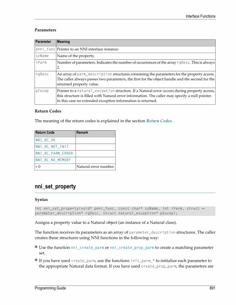
Parameters
MeaningParameter
Pointer to an NNI interface instance.pnni_func
Name of the property.szName
Number of parameters. Indicates the number of occurrences of the array rgDesc. This is always2.
iParm
An array of parm_description structures containing the parameters for the property access.The caller always passes two parameters, the first for the object handle and the second for thereturned property value.
rgDesc
Pointer to a natural_exception structure. If a Natural error occurs during property access,this structure is filled with Natural error information. The caller may specify a null pointer.In this case no extended exception information is returned.
pExcep
Return Codes
The meaning of the return codes is explained in the section Return Codes.
RemarkReturn Code
NNI_RC_OK
NNI_RC_NOT_INIT
NNI_RC_PARM_ERROR
NNI_RC_NO_MEMORY
Natural error number.> 0
nni_set_property
Syntax
int nni_set_property(void* pnni_func, const char* szName, int iParm, struct ↩parameter_description* rgDesc, struct natural_exception* pExcep);
Assigns a property value to a Natural object (an instance of a Natural class).
The function receives its parameters as an array of parameter_description structures. The callercreates these structures using NNI functions in the following way:
■ Use the function nni_create_parm or nni_create_prop_parm to create a matching parameterset.
■ If you have used create_parm, use the functions init_parm_* to initialize each parameter tothe appropriate Natural data format. If you have used create_prop_parm, the parameters are
891Programming Guide
Interface Functions
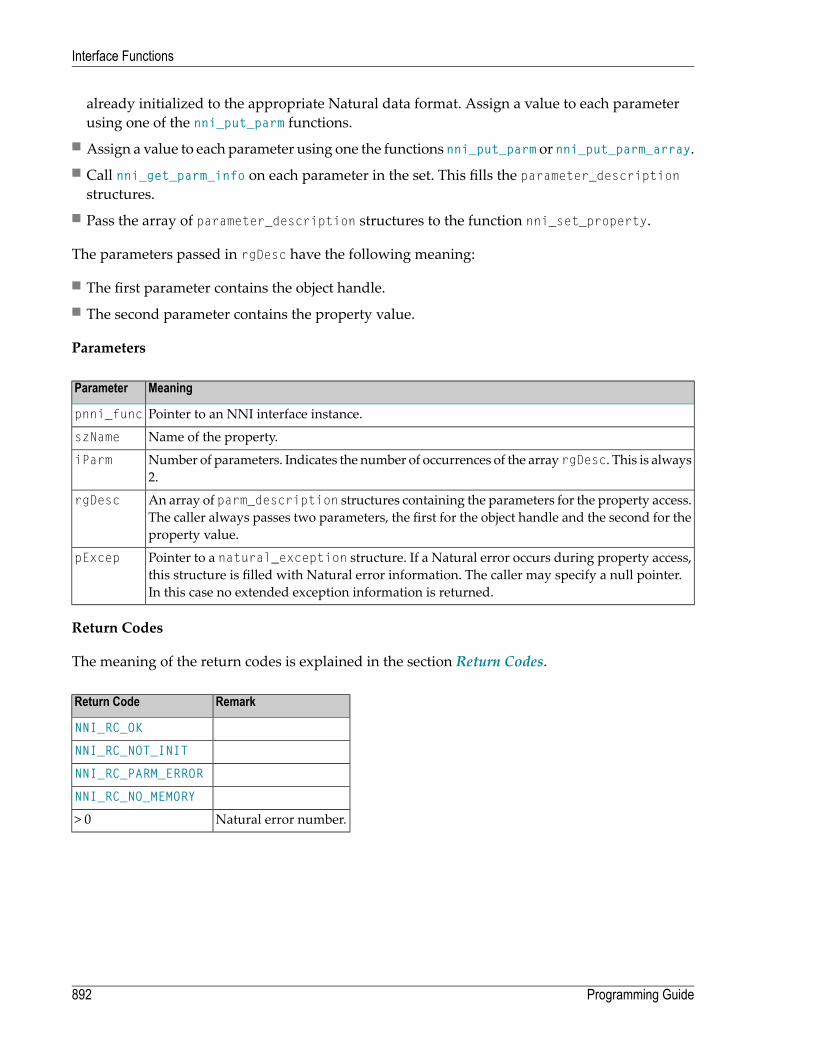
already initialized to the appropriate Natural data format. Assign a value to each parameterusing one of the nni_put_parm functions.
■ Assign a value to each parameter using one the functions nni_put_parm or nni_put_parm_array.■ Call nni_get_parm_info on each parameter in the set. This fills the parameter_descriptionstructures.
■ Pass the array of parameter_description structures to the function nni_set_property.
The parameters passed in rgDesc have the following meaning:
■ The first parameter contains the object handle.■ The second parameter contains the property value.
Parameters
MeaningParameter
Pointer to an NNI interface instance.pnni_func
Name of the property.szName
Number of parameters. Indicates the number of occurrences of the array rgDesc. This is always2.
iParm
An array of parm_description structures containing the parameters for the property access.The caller always passes two parameters, the first for the object handle and the second for theproperty value.
rgDesc
Pointer to a natural_exception structure. If a Natural error occurs during property access,this structure is filled with Natural error information. The caller may specify a null pointer.In this case no extended exception information is returned.
pExcep
Return Codes
The meaning of the return codes is explained in the section Return Codes.
RemarkReturn Code
NNI_RC_OK
NNI_RC_NOT_INIT
NNI_RC_PARM_ERROR
NNI_RC_NO_MEMORY
Natural error number.> 0
Programming Guide892
Interface Functions

nni_delete_object
Syntax
int nni_delete_object(void* pnni_func, int iParm, struct parameter_description* ↩rgDesc, struct natural_exception* pExcep);
Deletes a Natural object (an instance of a Natural class) created with nni_create_object.
The function receives its parameters as a one-element array of parameter_description structures.The caller creates the structures using NNI functions in the following way:
■ Use the function nni_create_parm to create parameter set with one element.■ Use the function nni_init_parm_s to initialize the parameter with the type HANDLE OF OBJECT.■ Assign a value to the parameter using one the functions nni_put_parm.■ Call nni_get_parm_info on this parameter. This fills the parameter_description structure.■ Pass the parameter_description structure to the function nni_delete_object.
The parameters passed in rgDesc have the following meaning:
■ The first (and only) parameter must be initialized with the data type HANDLE OF OBJECT andcontains the Natural object handle of the object to be deleted.
Parameters
MeaningParameter
Pointer to an NNI interface instance.pnni_func
Name of the class.szName
Number of parameters. Indicates the number of occurrences of the array rgDesc. This is always1.
iParm
An array of parm_description structures containing the parameters for the object creation.The caller always passes one parameter, which contains the object handle.
rgDesc
Pointer to a natural_exception structure. If a Natural error occurs during object creation,this structure is filled with Natural error information. The caller may specify a null pointer.In this case no extended exception information is returned.
pExcep
Return Codes
The meaning of the return codes is explained in the section Return Codes.
893Programming Guide
Interface Functions

RemarkReturn Code
NNI_RC_OK
NNI_RC_NOT_INIT
NNI_RC_PARM_ERROR
NNI_RC_NO_MEMORY
Natural error number.> 0
nni_create_parm
Syntax
int nni_create_parm(void* pnni_func, int iParm, void** pparmhandle);
Creates a set of parameters that can be passed to a Natural module.
The parameters contained in the set are not yet initialized to specific Natural data types. Beforeusing the parameter set in a call to nni_callnat, nni_create_object, nni_send_method,nni_set_property or nni_get_property:
■ Initialize each parameter to the required Natural data type using one of the functionsnni_init_parm_s, nni_init_parm_sa, nni_init_parm_d or nni_init_parm_da.
■ Assign a value to each parameter using one of the functions nni_put_parm ornni_put_parm_array.
■ Turn each parameter into a parm_description structure using the function nni_get_parm_info.
Parameters
MeaningParameter
Pointer to an NNI interface instance.pnni_func
Requested number of parameters. The maxinum number of parameters is 32767.iParm
Points a to a pointer to a parameter set on return.pparmhandle
Return Codes
The meaning of the return codes is explained in the section Return Codes.
Programming Guide894
Interface Functions

RemarkReturn Code
NNI_RC_OK
NNI_RC_NOT_INIT
NNI_RC_PARM_ERROR
NNI_RC_ILL_PNUM
Natural error number.> 0
nni_create_module_parm
Syntax
int nni_create_module_parm(void* pnni_func, char chType, const char* szName, void** ↩pparmhandle); ↩
Creates a set of parameters that can be used in a call to nni_callnat. The function enables an ap-plication to dynamically explore the signature of a callable Natural module.
The parameters contained in the returned set are already initialized toNatural data types accordingto the parameter data area of the specified module. Before using the parameter set in a call tonni_callnat:
■ Assign a value to each parameter using one of the functions nni_put_parm ornni_put_parm_array.
■ Turn each parameter into a parm_description structure using the function nni_get_parm_info.
Parameters
MeaningParameter
Pointer to an NNI interface instance.pnni_func
Type of the Natural module. Always N (for subprogram).chType
Name of the Natural module.szName
Points a to a pointer to a parameter set on return.pparmhandle
Return Codes
The meaning of the return codes is explained in the section Return Codes.
895Programming Guide
Interface Functions

RemarkReturn Code
NNI_RC_OK
NNI_RC_NOT_INIT
NNI_RC_PARM_ERROR
Natural error number.> 0
nni_create_method_parm
Syntax
int nni_create_method_parm( void* pnni_func, const char* szClass, const char* ↩szMethod, void** pparmhandle ); ↩
Creates a set of parameters that can be used in a call to nni_send_method. The function enablesan application to dynamically explore the signature of a method of a Natural class.
The returned parameter set contains not only themethod parameters, but also the other parametersrequired by nni_send_method. This means: If the method has n parameters, the parameter setcontains n + 2 parameters.
■ The first parameter in the set is initialized to the data type HANDLE OF OBJECT.■ The second parameter in the set is initialized to the data type of the method return value. If themethod does not have a return value, the second parameter is not initialized.
■ The remaining parameters in the set are initialized to the data types of the method parameters.
Before using the parameter set in a call to nni_send_method:
■ Assign a value to each parameter using one of the functions nni_put_parm ornni_put_parm_array.
■ Turn each parameter into a parm_description structure using the function nni_get_parm_info.
Parameters
MeaningParameter
Pointer to an NNI interface instance.pnni_func
Name of the Natural class.szClass
Name of the Natural method.szMethod
Points a to a pointer to a parameter set on return.pparmhandle
Return Codes
The meaning of the return codes is explained in the section Return Codes.
Programming Guide896
Interface Functions

RemarkReturn Code
NNI_RC_OK
NNI_RC_NOT_INIT
NNI_RC_PARM_ERROR
Natural error number.> 0
nni_create_prop_parm
Syntax
int nni_create_prop_parm(void* pnni_func, const char* szClass, const char* ↩szProp,void** pparmhandle); ↩
Creates a set of parameters that can be used in a call to nni_get_property or nni_set_property.The returned parameter set contains all parameters required by nni_get_property ornni_set_property. The function enables an application to determine the data type of a propertyof a Natural class.
■ The first parameter in the set is initialized to the data type HANDLE OF OBJECT.■ The second parameter in the set is initialized to the data type of the property.
Before using the parameter set in a call to nni_get_property or nni_set_property:
■ Assign a value to each parameter using one of the functions nni_put_parm ornni_put_parm_array.
■ Turn each parameter into a parm_description structure using the function nni_get_parm_info.
Parameters
MeaningParameter
Pointer to an NNI interface instance.pnni_func
Name of the Natural class.szClass
Name of the Natural property.szProp
Points a to a pointer to a parameter set on return.pparmhandle
Return Codes
The meaning of the return codes is explained in the section Return Codes.
897Programming Guide
Interface Functions

RemarkReturn Code
NNI_RC_OK
NNI_RC_NOT_INIT
NNI_RC_PARM_ERROR
Natural error number.> 0
nni_parm_count
Syntax
int nni_parm_count( void* pnni_func, void* parmhandle, int* piParm )
The function retrieves the number of parameters in a parameter set.
Parameters
MeaningParameter
Pointer to an NNI interface instance.pnni_func
Pointer to a parameter set.parmhandle
Returns the number of parameters in the parameter set.piParm
Return Codes
The meaning of the return codes is explained in the section Return Codes.
RemarkReturn Code
NNI_RC_OK
NNI_RC_NOT_INIT
NNI_RC_PARM_ERROR
nni_init_parm_s
Syntax
int nni_init_parm_s(void* pnni_func, int iParm, void* parmhandle, char chFormat, ↩int iLength, int iPrecision, int iFlags); ↩
Initializes a parameter in a parameter set to a static data type.
Programming Guide898
Interface Functions

Parameters
MeaningParameter
Pointer to an NNI interface instance.pnni_func
Index of the parameter. The first parameter in the set has the index 0.iParm
Pointer to a parameter set.parmhandle
Natural data type of the parameter.chFormat
Natural length of the parameter.iLength
Number of decimal places (NNI_TYPE_NUM and NNI_TYPE_PACK only).iPrecision
Parameter flags. The following flags can be used:iFlags
NNI_FLG_PROTECTED
Return Codes
The meaning of the return codes is explained in the section Return Codes.
RemarkReturn Code
NNI_RC_OK
NNI_RC_NOT_INIT
NNI_RC_PARM_ERROR
NNI_RC_ILL_PNUM
NNI_RC_NO_MEMORY
NNI_RC_BAD_FORMAT
NNI_RC_BAD_LENGTH
nni_init_parm_sa
Syntax
int nni_init_parm_sa (void* pnni_func, int iParm, void* parmhandle, char chFormat, ↩int iLength, int iPrecision, int iDim, int* rgiOcc, int iFlags); ↩
Initializes a parameter in a parameter set to an array of a static data type.
899Programming Guide
Interface Functions
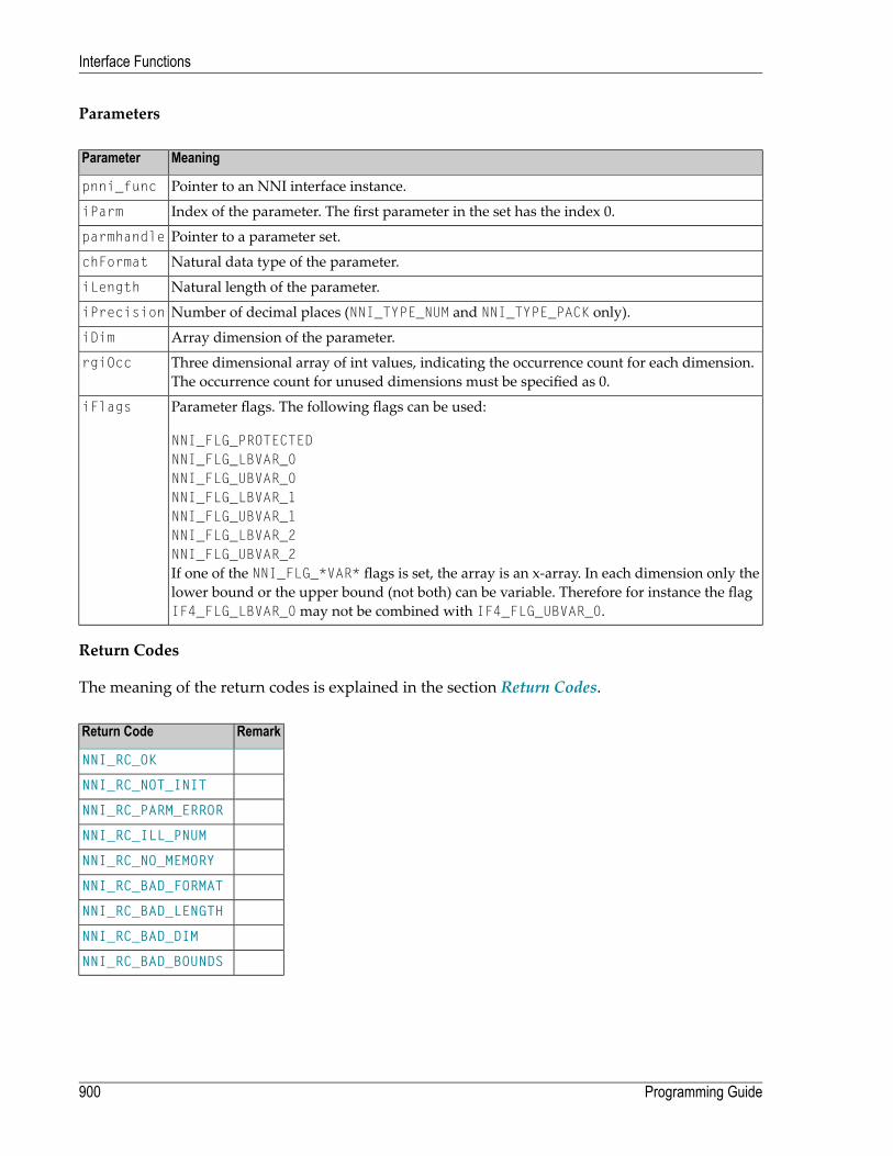
Parameters
MeaningParameter
Pointer to an NNI interface instance.pnni_func
Index of the parameter. The first parameter in the set has the index 0.iParm
Pointer to a parameter set.parmhandle
Natural data type of the parameter.chFormat
Natural length of the parameter.iLength
Number of decimal places (NNI_TYPE_NUM and NNI_TYPE_PACK only).iPrecision
Array dimension of the parameter.iDim
Three dimensional array of int values, indicating the occurrence count for each dimension.The occurrence count for unused dimensions must be specified as 0.
rgiOcc
Parameter flags. The following flags can be used:iFlags
NNI_FLG_PROTECTEDNNI_FLG_LBVAR_0NNI_FLG_UBVAR_0NNI_FLG_LBVAR_1NNI_FLG_UBVAR_1NNI_FLG_LBVAR_2NNI_FLG_UBVAR_2If one of the NNI_FLG_*VAR* flags is set, the array is an x-array. In each dimension only thelower bound or the upper bound (not both) can be variable. Therefore for instance the flagIF4_FLG_LBVAR_0may not be combined with IF4_FLG_UBVAR_0.
Return Codes
The meaning of the return codes is explained in the section Return Codes.
RemarkReturn Code
NNI_RC_OK
NNI_RC_NOT_INIT
NNI_RC_PARM_ERROR
NNI_RC_ILL_PNUM
NNI_RC_NO_MEMORY
NNI_RC_BAD_FORMAT
NNI_RC_BAD_LENGTH
NNI_RC_BAD_DIM
NNI_RC_BAD_BOUNDS
Programming Guide900
Interface Functions

nni_init_parm_d
Syntax
int nni_init_parm_d(void* pnni_func, int iParm, void* parmhandle, char chFormat, ↩int iFlags); ↩
Initializes a parameter in a parameter set to a dynamic data type.
Parameters
MeaningParameter
Pointer to an NNI interface instance.pnni_func
Index of the parameter. The first parameter in the set has the index 0.iParm
Pointer to a parameter set.parmhandle
Natural data type of the parameter (NNI_TYPE_ALPHA or NNI_TYPE_BIN).chFormat
Parameter flags. The following flags can be used:iFlags
NNI_FLG_PROTECTED
Return Codes
The meaning of the return codes is explained in the section Return Codes.
RemarkReturn Code
NNI_RC_OK
NNI_RC_NOT_INIT
NNI_RC_PARM_ERROR
NNI_RC_ILL_PNUM
NNI_RC_NO_MEMORY
NNI_RC_BAD_FORMAT
nni_init_parm_da
Syntax
int nni_init_parm_da (void* pnni_func, int iParm, void* parmhandle, char chFormat, ↩int iDim, int* rgiOcc, int iFlags); ↩
Initializes a parameter in a parameter set to an array of a dynamic data type.
901Programming Guide
Interface Functions
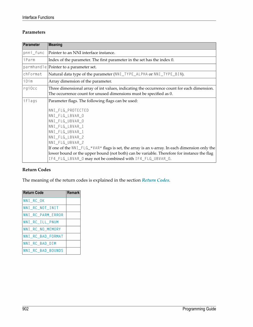
Parameters
MeaningParameter
Pointer to an NNI interface instance.pnni_func
Index of the parameter. The first parameter in the set has the index 0.iParm
Pointer to a parameter set.parmhandle
Natural data type of the parameter (NNI_TYPE_ALPHA or NNI_TYPE_BIN).chFormat
Array dimension of the parameter.iDim
Three dimensional array of int values, indicating the occurrence count for each dimension.The occurrence count for unused dimensions must be specified as 0.
rgiOcc
Parameter flags. The following flags can be used:iFlags
NNI_FLG_PROTECTEDNNI_FLG_LBVAR_0NNI_FLG_UBVAR_0NNI_FLG_LBVAR_1NNI_FLG_UBVAR_1NNI_FLG_LBVAR_2NNI_FLG_UBVAR_2If one of the NNI_FLG_*VAR* flags is set, the array is an x-array. In each dimension only thelower bound or the upper bound (not both) can be variable. Therefore for instance the flagIF4_FLG_LBVAR_0may not be combined with IF4_FLG_UBVAR_0.
Return Codes
The meaning of the return codes is explained in the section Return Codes.
RemarkReturn Code
NNI_RC_OK
NNI_RC_NOT_INIT
NNI_RC_PARM_ERROR
NNI_RC_ILL_PNUM
NNI_RC_NO_MEMORY
NNI_RC_BAD_FORMAT
NNI_RC_BAD_DIM
NNI_RC_BAD_BOUNDS
Programming Guide902
Interface Functions
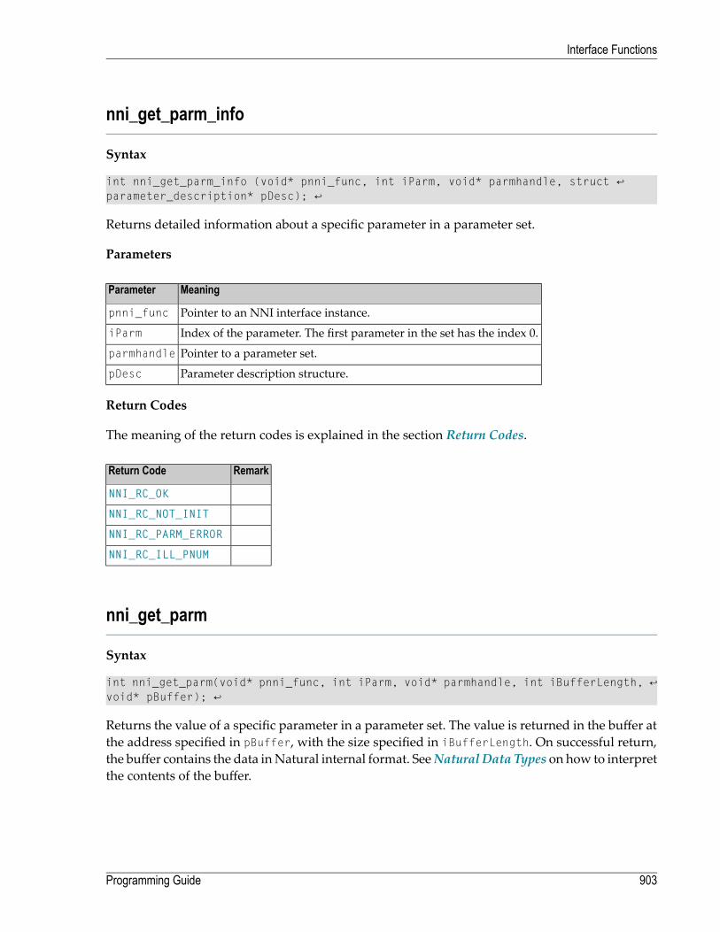
nni_get_parm_info
Syntax
int nni_get_parm_info (void* pnni_func, int iParm, void* parmhandle, struct ↩parameter_description* pDesc); ↩
Returns detailed information about a specific parameter in a parameter set.
Parameters
MeaningParameter
Pointer to an NNI interface instance.pnni_func
Index of the parameter. The first parameter in the set has the index 0.iParm
Pointer to a parameter set.parmhandle
Parameter description structure.pDesc
Return Codes
The meaning of the return codes is explained in the section Return Codes.
RemarkReturn Code
NNI_RC_OK
NNI_RC_NOT_INIT
NNI_RC_PARM_ERROR
NNI_RC_ILL_PNUM
nni_get_parm
Syntax
int nni_get_parm(void* pnni_func, int iParm, void* parmhandle, int iBufferLength, ↩void* pBuffer); ↩
Returns the value of a specific parameter in a parameter set. The value is returned in the buffer atthe address specified in pBuffer, with the size specified in iBufferLength. On successful return,the buffer contains the data inNatural internal format. SeeNatural Data Types on how to interpretthe contents of the buffer.
903Programming Guide
Interface Functions

If the length of the parameter according to the Natural data type is greater than iBufferLength,Natural truncates the data to the given length and returns the code NNI_RC_DATA_TRUNC. The callercan use the function nni_get_parm_info to request the length of the parameter value in advance.
If the length of the parameter according to the Natural data type is smaller than iBufferLength,Natural fills the buffer according to the length of the parameter and returns the length of the copieddata in the return code.
If the parameter is an array, the function returns the whole array in the buffer. This makes senseonly for fixed size arrays of fixed size elements, because in other cases the caller cannot interpretthe contents of the buffer. In order to retrieve an individual occurrence of an arbitrary array usethe function nni_get_parm_array.
If nomemory of the size specified in iBufferLength is allocated at the adress specified in pBuffer,the results of the operation are unpredictable. Natural only checks that pBuffer is not null.
Parameters
MeaningParameter
Pointer to an NNI interface instance.pnni_func
Index of the parameter. The first parameter in the set has the index 0.iParm
Pointer to a parameter set.parmhandle
Length of the buffer specified in pBuffer.iBufferLength
Buffer in which the value is returned.pBuffer
Return Codes
The meaning of the return codes is explained in the section Return Codes.
RemarkReturn Code
NNI_RC_OK
NNI_RC_NOT_INIT
NNI_RC_PARM_ERROR
NNI_RC_ILL_PNUM
NNI_RC_DATA_TRUNC
Successful operation, but only n bytes were returned in the buffer.= n, where n > 0
Programming Guide904
Interface Functions

nni_get_parm_array
Syntax
int nni_get_parm_array(void* pnni_func, int parmnum, void* parmhandle, int ↩iBufferLength, void* pBuffer, int* rgiInd);
Returns the value of a specific occurrence of a specific array parameter in a parameter set. Theonly difference to nni_get_parm is that array indices can be specified. The indices for unused di-mensions must be specified as 0.
Parameters
MeaningParameter
Pointer to an NNI interface instance.pnni_func
Index of the parameter. The first parameter in the set has the index 0.iParm
Pointer to a parameter set.parmhandle
Length of the buffer specified in pBuffer.iBufferLength
Buffer in which the value is returned.pBuffer
Three dimensional array of int values, indicating a specific array occurrence. The indicesstart with 0.
rgiInd
Return Codes
The meaning of the return codes is explained in the section Return Codes.
RemarkReturn Code
NNI_RC_OK
NNI_RC_NOT_INIT
NNI_RC_PARM_ERROR
NNI_RC_ILL_PNUM
NNI_RC_DATA_TRUNC
NNI_RC_NOT_ARRAY
NNI_RC_BAD_INDEX_0
NNI_RC_BAD_INDEX_1
NNI_RC_BAD_INDEX_2
Successful operation, but only n bytes were returned.= n, where n > 0
905Programming Guide
Interface Functions

nni_get_parm_array_length
Syntax
int nni_get_parm_array_length(void* pnni_func, int iParm, void* parmhandle, int* ↩piLength, int* rgiInd);
Returns the length of a specific occurrence of a specific array parameter in a parameter set.
Parameters
MeaningParameter
Pointer to an NNI interface instance.pnni_func
Index of the parameter. The first parameter in the set has the index 0.iParm
Pointer to a parameter set.parmhandle
Pointer to an int in which the length of the value is returned.piLength
Three dimensional array of int values, indicating a specific array occurrence. The indices startwith 0.
rgiInd
Return Codes
The meaning of the return codes is explained in the section Return Codes.
RemarkReturn Code
NNI_RC_OK
NNI_RC_ILL_PNUM
NNI_RC_DATA_TRUNC
NNI_RC_NOT_ARRAY
NNI_RC_BAD_INDEX_0
NNI_RC_BAD_INDEX_1
NNI_RC_BAD_INDEX_2
Programming Guide906
Interface Functions

nni_put_parm
Syntax
int nni_put_parm(void* pnni_func, int iParm, void* parmhandle, int iBufferLength, ↩const void* pBuffer); ↩
Assigns a value to a specific parameter in a parameter set. The value is passed to the function inthe buffer at the address specified in pBuffer, with the size specified in iBufferLength. See Nat-ural Data Types on how to prepare the contents of the buffer.
If the length of the parameter according to the Natural data type is smaller than the given bufferlength, the data will be truncated to the length of the parameter. The rest of the buffer will be ig-nored. If the length of the parameter according to the Natural data type is greater than the givenbuffer length, the data will copied only to the given buffer length, the rest of the parameter valuestays unchanged. See Natural Data Types on the internal length of Natural data types.
If the parameter is a dynamic variable, it is automatically resized according to the given bufferlength.
If the parameter is an array, the function expects the whole array in the buffer. This makes senseonly for fixed size arrays of fixed size elements, because in other cases the caller cannot providethe correct contents of the buffer. In order to assign a value to an individual occurrence of an ar-bitrary array use the function nni_put_parm_array.
Parameters
MeaningParameter
Pointer to an NNI interface instance.pnni_func
Index of the parameter. The first parameter in the set has the index 0.iParm
Pointer to a parameter set.parmhandle
Length of the buffer specified in pBuffer.iBufferLength
Buffer in which the value is passed.pBuffer
Return Codes
The meaning of the return codes is explained in the section Return Codes.
907Programming Guide
Interface Functions

RemarkReturn Code
NNI_RC_OK
NNI_RC_NOT_INIT
NNI_RC_PARM_ERROR
NNI_RC_ILL_PNUM
NNI_RC_WRT_PROT
NNI_RC_DATA_TRUNC
NNI_RC_NO_MEMORY
Successful operation, but only n bytes of the buffer were used.= n, where n > 0
nni_put_parm_array
Syntax
int nni_put_parm_array(void* pnni_func, int iParm, void* parmhandle, int ↩iBufferLength, const void* pBuffer, int* rgiInd);
Assigns a value to a specific occurrence of a specific array parameter in a parameter set. The onlydifference to nni_get_parm is that array indices can be specified. The indices for unused dimensionsmust be specified as 0.
Parameters
MeaningParameter
Pointer to an NNI interface instance.pnni_func
Index of the parameter. The first parameter in the set has the index 0.iParm
Pointer to a parameter set.parmhandle
Length of the buffer specified in pBuffer.iBufferLength
Buffer in which the value is passed.pBuffer
Three dimensional array of int values, indicating a specific array occurrence. The indicesstart with 0.
rgiInd
Return Codes
The meaning of the return codes is explained in the section Return Codes.
Programming Guide908
Interface Functions

RemarkReturn Code
NNI_RC_OK
NNI_RC_NOT_INIT
NNI_RC_PARM_ERROR
NNI_RC_ILL_PNUM
NNI_RC_WRT_PROT
NNI_RC_DATA_TRUNC
NNI_RC_NO_MEMORY
NNI_RC_NOT_ARRAY
NNI_RC_BAD_INDEX_0
NNI_RC_BAD_INDEX_1
NNI_RC_BAD_INDEX_2
Successful operation, but only n bytes of the buffer were used.= n, where n > 0
nni_resize_parm_array
Syntax
int nni_resize_parm_array(void* pnni_func, int iParm, void* parmhandle, int* rgiOcc); ↩
Changes the occurrence count of a specific x-array parameter in a parameter set. For an n-dimen-sional array an occurrence count must be specified for all n dimensions. If the dimension of thearray is less than 3, the value 0 must be specified for the not used dimensions.
The function tries to resize the occurrence count of each dimension either by changing the lowerbound or the upper bound, whatever is appropriate for the given x-array.
Parameters
MeaningParameter
Pointer to an NNI interface instance.pnni_func
Index of the parameter. The first parameter in the set has the index 0.iParm
Pointer to a parameter set.parmhandle
Three dimensional array of int values, indicating the new occurrence count of the array.rgiOcc
Return Codes
The meaning of the return codes is explained in the section Return Codes.
909Programming Guide
Interface Functions

RemarkReturn Code
NNI_RC_OK
NNI_RC_NOT_INIT
NNI_RC_PARM_ERROR
NNI_RC_ILL_PNUM
NNI_RC_WRT_PROT
NNI_RC_DATA_TRUNC
NNI_RC_NO_MEMORY
NNI_RC_NOT_ARRAY
NNI_RC_NOT_RESIZABLE
Natural error number.> 0
nni_delete_parm
Syntax
int nni_delete_parm(void* pnni_func, void* parmhandle);
Deletes the specified parameter set.
Parameters
MeaningParameter
Pointer to an NNI interface instance.pnni_func
Pointer to a parameter set.parmhandle
Return Codes
The meaning of the return codes is explained in the section Return Codes.
RemarkReturn Code
NNI_RC_OK
NNI_RC_NOT_INIT
NNI_RC_PARM_ERROR
Programming Guide910
Interface Functions

nni_from_string
Syntax
int nni_from_string(void* pnni_func, const char* szString, char chFormat, int ↩iLength, int iPrecision, int iBufferLength, void* pBuffer); ↩
Converts the string representation of a Natural P, N, D or T value into the internal representationof the value, as it is used in the functions nni_get_parm, nni_get_parm_array, nni_put_parm andnni_put_parm_array.
The string representations of these Natural data types look like this:
String representationFormat
For example, -3.141592, where the decimal character defined in the DC parameter is used.P, N
Date format as defined in the DTFORM parameter, (e. g. “2004-07-06”, if DTFORM=I).D
Date format as defined in the DTFORM parameter, combined with a Time value in the form hh:ii:ss:t(e. g. 2004-07-06 11:30:42:7, if DTFORM=I) or Time value in the formhh:ii:ss:t (e. g. 11:30:42:7).
T
Parameters
MeaningParameter
Pointer to an NNI interface instance.pnni_func
String representation of the value.szString
Natural data type of the value.chFormat
Natural length of the value. The total number of significant digits in the case ofNNI_TYPE_NUM and NNI_TYPE_PACK, 0 otherwise.
iLength
Number of decimal places in the case ofNNI_TYPE_NUM andNNI_TYPE_PACK, 0 otherwise.iPrecision
Length of the buffer provided in pBuffer.iBufferLength
Buffer that contains the internal representation of the value on return. The buffer mustbe large enough to hold the internal Natural representation of the value. The requiredsizes are documented in Format and Length of User-Defined Variables.
pBuffer
Return Codes
The meaning of the return codes is explained in the section Return Codes.
911Programming Guide
Interface Functions
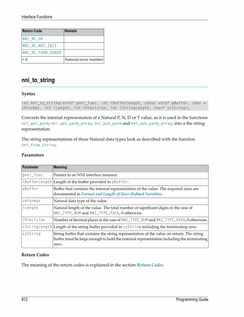
RemarkReturn Code
NNI_RC_OK
NNI_RC_NOT_INIT
NNI_RC_PARM_ERROR
Natural error number> 0
nni_to_string
Syntax
int nni_to_string(void* pnni_func, int iBufferLength, const void* pBuffer, char ↩chFormat, int iLength, int iPrecision, int iStringLength, char* szString);
Converts the internal representation of a Natural P, N, D or T value, as it is used in the functionsnni_get_parm, nni_get_parm_array, nni_put_parm and nni_put_parm_array, into a the stringrepresentation.
The string representations of these Natural data types look as described with the functionnni_from_string.
Parameters
MeaningParameter
Pointer to an NNI interface instance.pnni_func
Length of the buffer provided in pBuffer.iBufferLength
Buffer that contains the internal representation of the value. The required sizes aredocumented in Format and Length of User-Defined Variables.
pBuffer
Natural data type of the value.chFormat
Natural length of the value. The total number of significant digits in the case ofNNI_TYPE_NUM and NNI_TYPE_PACK, 0 otherwise.
iLength
Number of decimal places in the case ofNNI_TYPE_NUM andNNI_TYPE_PACK, 0 otherwise.iPrecision
Length of the string buffer provided in szString including the terminating zero.iStringLength
String buffer that contains the string representation of the value on return. The stringbuffermust be large enough to hold the external representation including the terminatingzero.
szString
Return Codes
The meaning of the return codes is explained in the section Return Codes.
Programming Guide912
Interface Functions

RemarkReturn Code
NNI_RC_OK
NNI_RC_NOT_INIT
NNI_RC_PARM_ERROR
Natural error number> 0
913Programming Guide
Interface Functions

914

118 Parameter Description Structure
The interface provides information about the parameters of a Natural subprogram or method ina structure named parameter_description. The structure is defined in the header file natuser.h.This file is contained in the directory%NATDIR%\%NATVERS%\samples\sysexnni.
An array of parameter_description structures is passed to the interface with each call tonni_callnat and similar functions. A parameter_description structure is created from a para-meter in a parameter set using the function nni_get_parm_info.
The relevant elements of the structure contain the following information. All elements not listedin this table are for internal use only.
ContentElement NameFormat
Address of the parameter value. Must not be reallocated or freed. The addresselement is a null pointer for arrays of dynamic variables and for x-arrays. In these
addressvoid*
cases, the array data cannot be accessed as a whole, but can only be accessedelementwise through the parameter access function nni_get_parm.
Natural data type of the parameter. Refer to Natural Data Types for furtherinformation.
formatint
Natural length of the parameter value. In the case of the data typesNNI_TYPE_ALPHA and NNI_TYPE_UNICODE, the number of characters. In the case
lengthint
of the data types NNI_TYPE_PACK and NNI_TYPE_NUM, the number of digits beforethe decimal character. In the case of an array, the length of a single occurrence. Inthe case of an array of dynamic variables, the length is indicatedwith 0. The lengthof an individual occurrence must then be determined with the functionnni_get_parm_array_length.
In the case of the data types NNI_TYPE_PACK and NNI_TYPE_NUM the number ofdigits after the decimal character, 0 otherwise.
precisionint
Length of the parameter value in bytes. In the case of an array the byte length ofa single occurrence. In the case of an array of dynamic variables the byte length is
byte_lengthint
indicated with 0. The length of an individual occurrence must then be determinedwith the function nni_get_parm_array_length.
915

ContentElement NameFormat
Number of dimensions. 0 in the case of a scalar. The maximum number ofdimensions is 3.
dimensionsint
Total length of the parameter value in bytes. In the case of an array the byte lengthof the whole array. In the case of an array of dynamic variables the total length is
length_allint
indicated with 0. The length of an individual occurrence must then be determinedwith the function nni_get_parm_array_length.
Parameter flags, see Flags.flagsint
Number of occurrences in each dimension. Only the first three occurrences areused.
occurrences[10]int
Array indexfactors for each dimension. Only the first three occurrences are used.indexfactors[10]int
In the case of arrays with fixed bounds of variables with fixed length, the array contents can beaccessed directly using the structure element address. In these cases the following applies:
■ The address of the element (i,j,k) of a three dimensional array is computed as follows:
elementaddress = address + i * indexfactors[0] + j * indexfactors[1] + k * indexfactors[2]■ The address of the element (i,j) of a two dimensional array is computed as follows:
elementaddress = address + i * indexfactors[0] + j * indexfactors[1]■ The address of the element (i) of a one dimensional array is computed as follows:
elementaddress = address + i * indexfactors[0]
Programming Guide916
Parameter Description Structure

119 Natural Data Types
Someof the parameter access functions (like nni_get_parm, nni_put_parm) use a buffer that containsa parameter value in the correct representation. The length of the buffer depends on the Naturaldata type. The data format of the buffer is defined according to the following table:
Buffer FormatNatural Data Type
char[ ]A
byte[ ]B
shortC
floatF4
doubleF8
signed charI1
shortI2
intI4
NNI_L_TRUE or NNI_L_FALSE, see natni.hL
byte[8]HANDLE OF OBJECT
The buffer content should be created from a string representationwith the functionnni_from_string. It can be transformed to a string representationwith the functionnni_to_string.
P, N, D, T
An array of UTF-16 characters. On Windows and on those UNIX and OpenVMSplatforms where a wchar corresponds to a UTF-16 character, this is a wchar[].
U
Some of the parameter access functions (like nni_get_parm, and nni_put_parm) require a Naturaldata type to be specified. In these cases the following constants should be used. The constants aredefined in the header file natni.h. This file is contained in the directory%NAT-DIR%\%NATVERS%\samples\sysexnni.
917

ConstantNatural Data Type
NNI_TYPE_ALPHAA
NNI_TYPE_BINB
NNI_TYPE_CVC
NNI_TYPE_DATED
NNI_TYPE_FLOATF
NNI_TYPE_INTI
NNI_TYPE_LOGL
NNI_TYPE_NUMN
NNI_TYPE_OBJECTHANDLE OF OBJECT
NNI_TYPE_PACKP
NNI_TYPE_TIMET
NNI_TYPE_UNICODEU
Programming Guide918
Natural Data Types

120 Flags
The structure parameter_description has an element flags that contains information about thestatus of the parameter. Also the functions nni_init_parm* allow specifying some of these flagswhe initializing a parameter. The individual flags can be combinedwith a logical OR in the elementflags. The following flags are defined in the header file natni.h. This file is contained in the directory%NATDIR%\%NATVERS%\samples\sysexnni.
MeaningReturn Code
Parameter is write protected.NNI_FLG_PROTECTED
Parameter is dynamic (variable length or x-array).NNI_FLG_DYNAMIC (*)
Array is not contiguous.NNI_FLG_NOT_CONTIG (*)
Parameter is an AIV or INDEPENDENT variable.NNI_FLG_AIV (*)
Parameter has variable length.NNI_FLG_DYNVAR (*)
Parameter is an x-array.NNI_FLG_XARRAY (*)
Lower bound of dimension 0 is variable.NNI_FLG_LBVAR_0
Upper bound of dimension 0 is variable.NNI_FLG_UBVAR_0
Lower bound of dimension 1 is variable.NNI_FLG_LBVAR_1
Upper bound of dimension 1 is variable.NNI_FLG_UBVAR_1
Lower bound of dimension 2 is variable.NNI_FLG_LBVAR_2
Upper bound of dimension 2 is variable.NNI_FLG_UBVAR_2
Only the flags marked with (*) can be explicitly set in the functions nni_init_parm*. The otherflags are automatically set by the interface according to the type of the parameter.
If one of the NNI_FLG_*VAR* flags is set, the array is an x-array. In each dimension of an x-arrayonly the lower bound or the upper bound, not both, can be variable. Therefore for instance theflag NNI_FLG_LBVAR_0may not be combined with NNI_FLG_UBVAR_0.
919

If NNI_FLG_DYNAMIC is on, also NNI_FLG_DYNVAR, NNI_FLG_XARRAY or both are on. If both are on,the parameter is an x-array with elements of variable length.
Programming Guide920
Flags
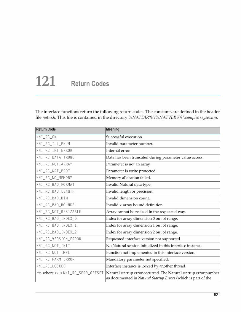
121 Return Codes
The interface functions return the following return codes. The constants are defined in the headerfile natni.h. This file is contained in the directory%NATDIR%\%NATVERS%\samples\sysexnni.
MeaningReturn Code
Successful execution.NNI_RC_OK
Invalid parameter number.NNI_RC_ILL_PNUM
Internal error.NNI_RC_INT_ERROR
Data has been truncated during parameter value access.NNI_RC_DATA_TRUNC
Parameter is not an array.NNI_RC_NOT_ARRAY
Parameter is write protected.NNI_RC_WRT_PROT
Memory allocation failed.NNI_RC_NO_MEMORY
Invalid Natural data type.NNI_RC_BAD_FORMAT
Invalid length or precision.NNI_RC_BAD_LENGTH
Invalid dimension count.NNI_RC_BAD_DIM
Invalid x-array bound definition.NNI_RC_BAD_BOUNDS
Array cannot be resized in the requested way.NNI_RC_NOT_RESIZABLE
Index for array dimension 0 out of range.NNI_RC_BAD_INDEX_0
Index for array dimension 1 out of range.NNI_RC_BAD_INDEX_1
Index for array dimension 2 out of range.NNI_RC_BAD_INDEX_2
Requested interface version not supported.NNI_RC_VERSION_ERROR
No Natural session initialized in this interface instance.NNI_RC_NOT_INIT
Function not implemented in this interface version.NNI_RC_NOT_IMPL
Mandatory parameter not specified.NNI_RC_PARM_ERROR
Interface instance is locked by another thread.NNI_RC_LOCKED
Natural startup error occurred. The Natural startup error numberas documented in Natural Startup Errors (which is part of the
rc, where rc < NNI_RC_SERR_OFFSET
921

MeaningReturn Code
Operationsdocumentation) can be determined from the return codeby the following calculation:
startup-error-nr = - (rc - NNI_RC_SERR_OFFSET)
Natural error number.> 0
Programming Guide922
Return Codes
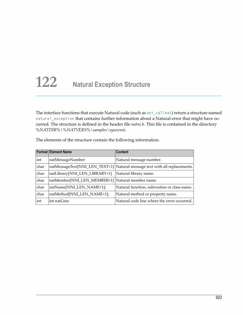
122 Natural Exception Structure
The interface functions that execute Natural code (such as nni_callnat) return a structure namednatural_exception that contains further information about a Natural error that might have oc-curred. The structure is defined in the header file natni.h. This file is contained in the directory%NATDIR%\%NATVERS%\samples\sysexnni.
The elements of the structure contain the following information.
ContentElement NameFormat
Natural message number.natMessageNumberint
Natural message text with all replacements.natMessageText[NNI_LEN_TEXT+1]char
Natural library name.natLibrary[NNI_LEN_LIBRARY+1]char
Natural member name.natMember[NNI_LEN_MEMBER+1]char
Natural function, subroutine or class name.natName[NNI_LEN_NAME+1];char
Natural method or property name.natMethod[NNI_LEN_NAME+1];char
Natural code line where the error occurred.int natLine;int
923

924
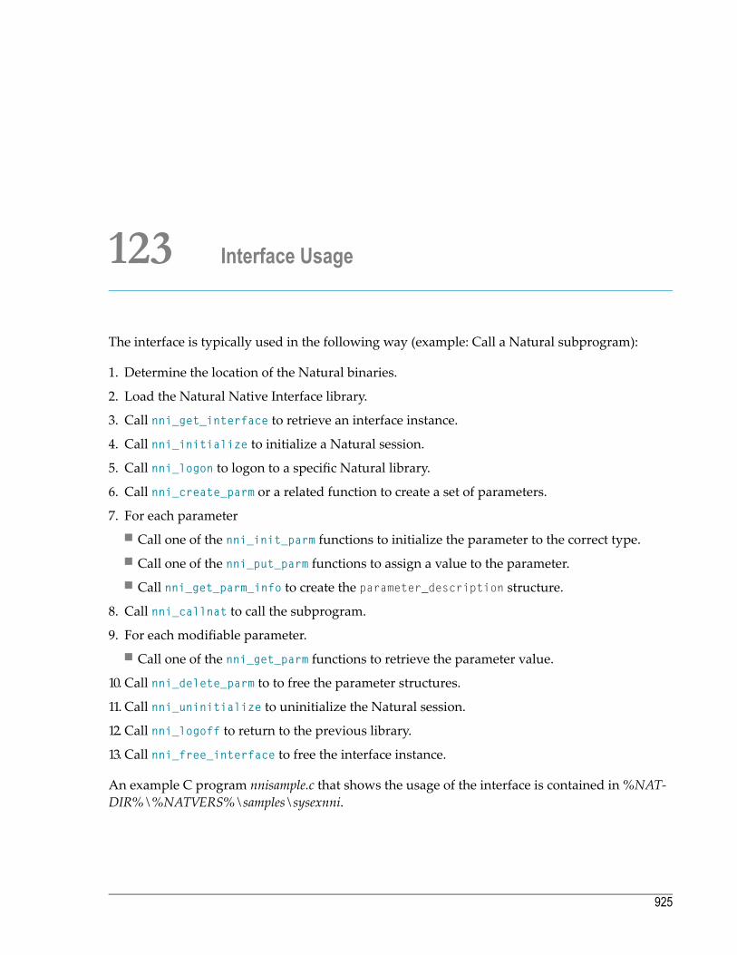
123 Interface Usage
The interface is typically used in the following way (example: Call a Natural subprogram):
1. Determine the location of the Natural binaries.
2. Load the Natural Native Interface library.
3. Call nni_get_interface to retrieve an interface instance.
4. Call nni_initialize to initialize a Natural session.
5. Call nni_logon to logon to a specific Natural library.
6. Call nni_create_parm or a related function to create a set of parameters.
7. For each parameter■ Call one of the nni_init_parm functions to initialize the parameter to the correct type.■ Call one of the nni_put_parm functions to assign a value to the parameter.■ Call nni_get_parm_info to create the parameter_description structure.
8. Call nni_callnat to call the subprogram.
9. For each modifiable parameter.■ Call one of the nni_get_parm functions to retrieve the parameter value.
10. Call nni_delete_parm to to free the parameter structures.
11. Call nni_uninitialize to uninitialize the Natural session.
12. Call nni_logoff to return to the previous library.
13. Call nni_free_interface to free the interface instance.
An example C program nnisample.c that shows the usage of the interface is contained in%NAT-DIR%\%NATVERS%\samples\sysexnni.
925

926

124 Threading Issues
ANatural process onWindows,UNIX andOpenVMSalways contains only one thread that executesNatural code. Thus in an interactively started Natural session, it can never occur that severalthreads try to execute Natural code in parallel. The situation is different when a client programthat runs several threads in parallel uses the Natural Native Interface.
The Natural Native Interface can be used by multithreaded applications. The interface functionsare thread safe. As long as a given thread T is executing one of the interface functions, other threadsof the same process that call one of the interface functions are blocked until T has left the interfacefunction. Effectively the parallel executing threads of the process are serialized as far as the usageof the interface functions is concerned. It is not necessary to serialize interface access among thethreads of different processes, because each different process that uses the NNI runs its ownNatural session.
The calling application can also control the multithreaded access to the NNI explicitly. This canmake sense if a threadwants to execute a series of NNI calls without being interrupted by anotherthread. To achieve this, the thread calls nni_enter, which lets the threadwait until all other threadshave left the NNI. Then the thread does its work and calls NNI functions at will. After havingfinished its work, the thread calls nni_leave to allow other threads to access the NNI.
A multithreaded application that uses the NNI must follow these rules:
■ The functions nni_initialize and nni_uninitializemust be called at least once per process.■ The function nni_uninitializemust be called on the same thread as the corresponding call tonni_initialize.
■ The function nni_uninitializemust not be called before the last thread that uses the NNI hasterminated.
927

928

XIV NaturalX
This part describes how to develop and distribute object-based applications.
The following topics are covered:
Introduction to NaturalX
Developing NaturalX Applications
Distributing NaturalX Applications
ActiveX Component SoftwareAG.NaturalX.Utilities
Interface INaturalXUtilities
Interface IRunningObjects
ActiveX Component SoftwareAG.NaturalX.Enumerator
Interface IEnumerator
929

930

125 Introduction to NaturalX
■ Why NaturalX? .............................................................................................................................. 932■ Programming Techniques ................................................................................................................ 933
931

This chapter contains a short introduction to component-based programming involving the useof the NaturalX interface and a dedicated set of Natural statements.
Why NaturalX?
Software applications that are based on component architecture offer many advantages over tra-ditional designs. These include the following:
■ Faster development. Programmers can build applications faster by assembling software fromprebuilt components.
■ Reduced development costs. Having a common set of interfaces for programs means less workintegrating the components into complete solutions.
■ Improvedflexibility. It is easier to customize software for different departmentswithin a companyby just changing some of the components that constitute the application.
■ Reduced maintenance costs. In the case of an upgrade, it is often sufficient to change some ofthe components instead of having to modify the entire application.
■ Easier distribution. Components encapsulate data structures and functionality in distributableunits.
Using NaturalX you can create component-based applications.
You can use NaturalX in conjunction with DCOM. This enables you to:
■ allow your components to be accessed by other components,■ execute these components on local and/or remote servers,■ access components written in a variety of programming languages across process and machineboundaries from within Natural programs,
■ provide your existing Natural applications with (quasi) standardized interfaces.
The following scenario illustrates how a company could exploit these advantages. A companyintroduces a new sales management system that is based on an application design using compon-ents. There are numerous data entry components in the application, one for each sales point. Butall of these sales points use a common tax calculation component that runs on a server. If the taxlegislation is changed, then only the tax component has to be updated instead of changing thedata entry components at each site. In addition, the life of the programmers ismade easier becausethey do not have to worry about network programming and the integration of components thatare written in different languages.
Programming Guide932
Introduction to NaturalX
Programming Techniques
This section covers the following topics:
■ Object-Based Programming■ Defining Classes■ Defining Interfaces■ Interface Inheritance
Object-Based Programming
NaturalX follows an object-based programming approach. Characteristic for this approach is theencapsulation of data structures with the corresponding functionality into classes. Encapsulationis a good basis for easy distribution. Because there are (quasi) standards for the interoperation ofsoftware components on the basis of object models, an object-based approach is also a good basisfor making software components interoperable across program, machine and programming lan-guage boundaries.
Defining Classes
In an object-based application, each function is considered to be a service that is provided by anobject. Each object belongs to a class. Clients use the services either to perform a business task orto build even more complex services and to provide these to other clients. Hence the basic step increating an application with NaturalX is to define the classes that form the application. In manycases, the classes simply correspond to the real things that the application in question deals with,for example, bank accounts, aircraft, shipments etc. There is a wide range of good literature aboutobject-oriented design, and a number of well-proven methods can be used to identify the classesin a given business.
The process of defining a class can be broadly broken down into the following steps:
■ Create a Natural module of type class.■ Specify the name of the class using the DEFINE CLASS statement. This name will be used by theclients to create objects of that class.
■ Use the OBJECT clause of the DEFINE DATA statement to define how an object of the class willlook internally. Create a local data area that describes the layout of the object with the data areaeditor, and assign this data area in the OBJECT clause.
These steps are described in more detail in the section Developing Object-Based Natural Applic-ations.
933Programming Guide
Introduction to NaturalX

Defining Interfaces
In order to be useful to clients, a class must provide services, which it does through interfaces. Aninterface is a collection of methods and properties. A method is a function that an object of theclass can perform when requested by a client. A property is an attribute of an object that a clientcan retrieve or change. A client accesses the services by creating an object of the class and usingthe methods and properties of its interfaces.
The process of defining an interface can be broadly broken down into the following steps:
■ Use the INTERFACE clause to specify an interface name.■ Define the properties of the interface with PROPERTY definitions.■ Define the methods of the interface with METHOD definitions.
These steps are described in more detail in the section Developing Object-Based Natural Applic-ations.
Simple classes only have one interface, but a class may have more than one interface. This possib-ility can be used to group methods and properties into one interface that belong to the samefunctional aspect of the class and to define different interfaces to handle other functional aspects.For example, an Employee class could have an interface Administration that contains all of themethods and properties of the administrative aspects of an employee. This interface could containthe properties Salary and Department and themethod TransferToDepartment. Another interfaceQualifications could contain the qualification aspects of an employee.
Interface Inheritance
Defining several interfaces for a class is the first step towards using interface inheritance, whichis a more advanced method of designing classes and interfaces. This makes it possible to reusethe same interface definition in different classes. Assume that there is a class Manager, which is tobe treated in the same way as the class Employeewith respect to qualification, but which is to behandled differently as far as administration is concerned. This can be achieved by having theQualification interface in both classes. This has the advantage that a client that uses theQualification interface on a given object does not have to check explicitly whether the objectrepresents an Employee or a Manager. It can simply use the same methods and properties withouthaving to know of what class the object is. The properties or methods can even be implementedin a differentway in both classes provided they are presented through the same interface definition.
The process of using interface inheritance can be broadly broken down into the following steps:
■ Use the INTERFACE statements to define one ormore interfaces in a copycode instead of definingthem directly in the class.
■ The METHOD and PROPERTY definitions in the INTERFACE statement do not need to contain the ISclause. At this point, you just define the external appearance of the interface without assigningimplementations to the methods and properties.
Programming Guide934
Introduction to NaturalX

■ Use the INTERFACE clause to include the copycode with its interface definition in each class thatwill implement the interface.
■ Use the METHOD and PROPERTY statements to assign implementations to themethods andpropertiesof the interface in each class that will implement the interface.
935Programming Guide
Introduction to NaturalX

936
126 Developing NaturalX Applications
■ Development Environments ............................................................................................................. 938■ Defining Classes ........................................................................................................................... 938■ Using Classes and Objects .............................................................................................................. 943
937

This chapter describes how to develop an application by defining and using classes.
Development Environments
■ Developing Classes on Windows PlatformsOnWindows platforms, Natural provides the Class Builder as the tool to develop Naturalclasses. The Class Builder shows a Natural class in a structured hierarchical order and allowsthe user to manage the class and its components efficiently. If you use the Class Builder, noknowledge or only a basic knowledge of the syntax elements described below is required.
■ Developing Classes Using SPoDIn aNatural Single Point ofDevelopment (SPoD) environment that includes aMainframe,UNIXand/or OpenVMS remote development server, you can use the Class Builder available with theNatural Studio front-end to develop classes on Mainframe, UNIX and/or OpenVMS platforms.In this case, no knowledge or only a basic knowledge of the syntax elements described belowis required.
■ Developing Classes on Mainframe, UNIX or OpenVMS PlatformsIf you do not use SPoD, you develop classes on these platforms using the Natural program ed-itor. In this case, you should know the syntax of class definition described below.
Defining Classes
When you define a class, youmust create aNatural classmodule, withinwhich you create a DEFINECLASS statement. Using the DEFINE CLASS statement, you assign the class an externally usablename and define its interfaces, methods and properties. You can also assign an object data areato the class, which describes the layout of an instance of the class. The DEFINE CLASS statement isalso used to supply a global unique identifier to those classes that are to be registered as COMclasses.
This section covers the following topics:
■ Creating a Natural Class Module■ Specifying a Class■ Defining an Interface■ Assigning an Object Data Variable to a Property■ Assigning a Subprogram to a Method
Programming Guide938
Developing NaturalX Applications
■ Implementing Methods
Creating a Natural Class Module
To create a Natural class module
■ Use the CREATE OBJECT statement to create a Natural object of type Class.
Specifying a Class
The DEFINE CLASS statement defines the name of the class, the interfaces the class supports andthe structure of its objects. For classes that are to be registered as COM classes, it specifies also theglobally unique ID of the class and its activation policy.
To specify a class
■ Use the DEFINE CLASS statement as described in the Statements documentation.
Defining an Interface
Each interface of a class is specified with an INTERFACE statement inside the class definition. AnINTERFACE statement specifies the name of the interface and a number of properties andmethods.For classes that are to be registered as COM classes, it specifies also the globally inique ID of theinterface.
A class can have one or several interfaces. For each interface, one INTERFACE statement is codedin the class definition. Each INTERFACE statement contains one or several PROPERTY and METHODclauses. Usually the properties and methods contained in one interface are related from either atechnical or a business point of view.
The PROPERTY clause defines the name of a property and assigns a variable from the object dataarea to the property. This variable is used to store the value of the property.
The METHOD clause defines the name of a method and assigns a subprogram to the method. Thissubprogram is used to implement the method.
To define an interface
■ Use the INTERFACE statement as described in the Statements documentation.
939Programming Guide
Developing NaturalX Applications
Assigning an Object Data Variable to a Property
The PROPERTY statement is used only when several classes are to implement the same interface indifferent ways. In this case, the classes share the same interface definition and include it from aNatural copycode. The PROPERTY statement is then used to assign a variable from the object dataarea to a property, outside the interface definition. Like the PROPERTY clause of the INTERFACEstatement, the PROPERTY statement defines the name of a property and assigns a variable from theobject data area to the property. This variable is used to store the value of the property.
To assign an object data variable to a property
■ Use the PROPERTY statement as described in the Statements documentation.
Assigning a Subprogram to a Method
The METHOD statement is used only when several classes are to implement the same interface indifferent ways. In this case, the classes share the same interface definition and include it from aNatural copycode. The METHOD statement is then used to assign a subprogram to themethod, outsidethe interface definition. Like the METHOD clause of the INTERFACE statement, the METHOD statementdefines the name of a method and assigns a subprogram to the method. This subprogram is usedto implement the method.
To assign a subprogram to a method
■ Use the METHOD statement as described in the Statements documentation.
Implementing Methods
A method is implemented as a Natural subprogram in the following general form:
DEFINE DATA statement** Implementation code of the method*END
For information on the DEFINE DATA statement see the Statements documentation.
All clauses of the DEFINE DATA statement are optional.
It is recommended that you use data areas instead of inline data definitions to ensure data consist-ency.
If a PARAMETER clause is specified, the method can have parameters and/or a return value.
Programming Guide940
Developing NaturalX Applications

Parameters that are marked BY VALUE in the parameter data area are input parameters of themethod.
Parameters that are not marked BY VALUE are passed “by reference” and are input/output para-meters. This is the default.
The first parameter that ismarked BY VALUE RESULT is returned as the return value for themethod.If more than one parameter is marked in this way, the others will be treated as input/outputparameters.
Parameters that are marked OPTIONAL need not be specified when the method is called. They canbe left unspecified by using the nX notation in the SEND METHOD statement.
To make sure that the method subprogram accepts exactly the same parameters as specified inthe corresponding METHOD statement in the class definition, use a parameter data area instead ofinline data definitions. Use the same parameter data area as in the corresponding METHOD statement.
To give the method subprogram access to the object data structure, the OBJECT clause can be spe-cified. To make sure that the method subprogram can access the object data correctly, use a localdata area instead of inline data definitions. Use the same local data area as specified in the OBJECTclause of the DEFINE CLASS statement.
The GLOBAL, LOCAL and INDEPENDENT clauses can be used as in any other Natural program.
While technically possible, it is usually not meaningful to use a CONTEXT clause in a method sub-program.
The following example retrieves data about a given person from a table. The search key is passedas a BY VALUE parameter. The resulting data is returned through “by reference” parameters (“byreference” is the default definition). The return value of the method is defined by the specificationBY VALUE RESULT.
941Programming Guide
Developing NaturalX Applications
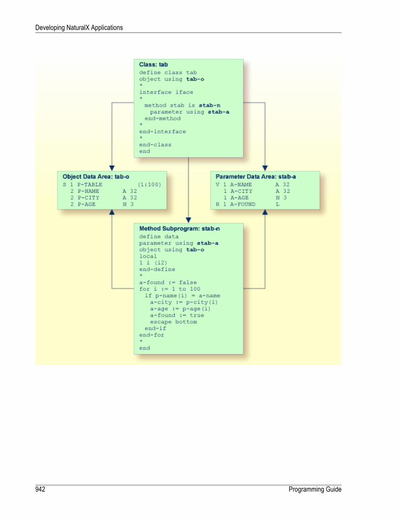
Programming Guide942
Developing NaturalX Applications

Using Classes and Objects
Objects created in a local Natural session can be accessed by other modules in the same Naturalsession.
Objects created in other processes or on remote machines can be accessed via DCOM.
In both cases the rules for accessing and using classes and their objects are the same.
The statement CREATE OBJECT is used to create an object (also known as an instance) of a givenclass.
To reference objects in Natural programs, object handles have to be defined in the DEFINE DATAstatement. Methods of an object are invoked with the statement SEND METHOD. Objects can haveproperties, which can be accessed using the normal assignment syntax.
Note: In order to use a NaturalX class via DCOM, the class must first be registered.
These steps are described below:
■ Defining Object Handles■ Creating an Instance of a Class■ Invoking a Particular Method of an Object■ Accessing Properties■ Sample Application
Defining Object Handles
To reference objects in Natural programs, object handles have to be defined as follows in theDEFINE DATA statement:
DEFINE DATA
level-handle-name [(array-definition)] HANDLE OF OBJECT
...
END-DEFINE
Example:
943Programming Guide
Developing NaturalX Applications

DEFINE DATA LOCAL1 #MYOBJ1 HANDLE OF OBJECT1 #MYOBJ2 (1:5) HANDLE OF OBJECTEND-DEFINE
Creating an Instance of a Class
To create an instance of a class
■ Use the CREATE OBJECT statement as described in the Statements documentation.
Invoking a Particular Method of an Object
To invoke a particular method of an object
■ Use the SEND METHOD statement as described in the Statements documentation.
Accessing Properties
Properties can be accessed using the ASSIGN (or COMPUTE ) statement as follows:
ASSIGN operand1.property-name = operand2
ASSIGN operand2 = operand1.property-name
Object Handle - operand1
operand1must be defined as an object handle and identifies the object whose property is to beaccessed. The object must already exist.
operand2
As operand2, you specify an operandwhose formatmust be data transfer-compatible to the formatof the property. Please refer to the data transfer compatibility rules for further information.
If the object is to be accessed via DCOM, you must also take into account the rules for data typeconversionwhich are outlined in the sectionUsing Type Information in theOperationsdocumentation.
property-name
The name of a property of the object.
If the property name conforms to Natural identifier syntax, it can be specified as follows
Programming Guide944
Developing NaturalX Applications
create object #o1 of class "Employee"#age := #o1.Age
If the property name does not conform to Natural identifier syntax, it must be enclosed in anglebrackets:
create object #o1 of class "Employee"#salary := #o1.<<%Salary>>
The property name can also be qualified with an interface name. This is necessary if the object hasmore than one interface containing a property with the same name. In this case, the qualifiedproperty name must be enclosed in angle brackets:
create object #o1 of class "Employee"#age := #o1.<<PersonalData.Age>>
Example:
define datalocal1 #i (i2)1 #o handle of object1 #p (5) handle of object1 #q (5) handle of object1 #salary (p7.2)1 #history (p7.2/1:10)end-define* ...* Code omitted for brevity.* ...* Set/Read the Salary property of the object #o.#o.Salary := #salary#salary := #o.Salary* Set/Read the Salary property of* the second object of the array #p.#p.Salary(2) := #salary#salary := #p.Salary(2)** Set/Read the SalaryHistory property of the object #o.#o.SalaryHistory := #history(1:10)#history(1:10) := #o.SalaryHistory* Set/Read the SalaryHistory property of* the second object of the array #p.#p.SalaryHistory(2) := #history(1:10)#history(1:10) := #p.SalaryHistory(2)*
945Programming Guide
Developing NaturalX Applications
* Set the Salary property of each object in #p to the same value.#p.Salary(*) := #salary* Set the SalaryHistory property of each object in #p* to the same value.#p.SalaryHistory(*) := #history(1:10)** Set the Salary property of each object in #p to the value* of the Salary property of the corresponding object in #q.#p.Salary(*) := #q.Salary(*)* Set the SalaryHistory property of each object in #p to the value* of the SalaryHistory property of the corresponding object in #q.#p.SalaryHistory(*) := #q.SalaryHistory(*)*end
In order to use arrays of object handles and properties that have arrays as values correctly, it isimportant to know the following:
A property of an occurrence of an array of object handles is addressed with the following indexnotation:
#p.Salary(2) := #salary
A property that has an array as value is always accessed as a whole. Therefore no index notationis necessary with the property name:
#o.SalaryHistory := #history(1:10)
A property of an occurrence of an array of object handles which has an array as value is thereforeaddressed as follows:
#p.SalaryHistory(2) := #history(1:10)
Sample Application
An example application is provided in the libraries SYSEXCOM and SYSEXCOC. See the A-README members in these libraries for information about how to run the example.
Programming Guide946
Developing NaturalX Applications
127 Distributing NaturalX Applications
■ General ....................................................................................................................................... 948■ Globally Unique Identifiers - GUIDs ................................................................................................... 950
947
An application consisting of NaturalX classes can be distributed across several processes andmachines using DCOM.
See also Using Statements and Commands in a NaturalX Server Environment in the Operations docu-mentation.
General
Using NaturalX, you can make Natural classes and their services available to local and remoteclients, thus creating distributed applications. Local clients are processes that run on the samemachine as a given NaturalX server, and remote clients are processes that run on a different ma-chine.
In order to distribute applications, a widely used distributed object technology is used - the Mi-crosoft Distributed Component Object Model (DCOM). When you register a Natural class toDCOM, its interfaces are presented to clients in a quasi-standardized fashion as dynamic COMinterfaces, which are also known as dispatch interfaces. These interfaces can be easily addressedby many programming languages including Visual Basic, Java, C++ and, of course, Natural.
There are several points that must be taken into consideration when organizing the distributionof a NaturalX application. Each of these points is discussed in more detail in this section and inthe Operations documentation.
■ Determine whether each class should be internal, external or local (see the section Internal, Ex-ternal and Local Classes).
■ Globally unique IDs (GUIDs) must be assigned to the internal and external classes and theirinterfaces in order to be able to address them uniquely in the network (see the sectionGloballyUnique Idenitfiers (GUIDs)).
■ You can define the activation policy for each class in order to control the conditions underwhichDCOM activates it (see section Activation Policies in the Operations documentation).
■ In order to organize classes to applications, you can define NaturalX servers and assign theclasses to them (see the section NaturalX Servers in the Operations documentation).
■ Classes must be registered to make them known to DCOM (see section Registration in theOper-ations documentation).
■ You can configure an application in order to further control its behavior (see the sectionsConfig-uration Overview and DCOM Configuration on Windows in the Operations documentation).
Programming Guide948
Distributing NaturalX Applications

Internal, External and Local Classes
It is important to distinguish between classes for internal use, classes for external use and thosefor local use only.
Internal Classes
Objects (instances) of internal classes can only be created in the client process.
Internal classes have the following features:
■ Access to client session-dependent resources such as files and system variables.■ Can run within the client transaction.■ Can be debugged using the Natural debugger (local debugging).
External Classes
Objects (instances) of external classes can be created in a different process or on a differentmachine.If the client process is simultaneously a server for the class, they can also be created in the clientprocess.
External classes have the following features:
■ No access to client session-dependent resources such as stacks, files and system variables.■ Do not run within the client transaction.■ Can be used by remote nodes.■ Can be used by various clients using a variety of languages such as Natural, Java, Visual Basic,C/C++, etc.
■ Can be debugged with the Natural debugger (remote debugging).
Local Classes
Local classes are classes, which are executed in local execution mode. Natural executes a classlocally (within the Natural session) if it is either not registered or if DCOM is not available.
Local classes have the following features:
■ Can be used even if DCOM is not available.■ Need not be registered with DCOM.■ Cannot be used from outside the client process.
949Programming Guide
Distributing NaturalX Applications
Globally Unique Identifiers - GUIDs
DCOM uses global unique identifiers (GUIDs) - 128-bit integers that are virtually guaranteed tobe unique throughout the world - to identify every interface and every class. This helps to ensurethat server components can be located and to prevent clients connecting to an object accidentally.
If a class is to be registered to DCOM, every interface defined in a Natural class and the class itselfmust be associated with such a globally unique ID.
Once a globally unique ID has been assigned to an interface or a class, the ID must never bechanged.
Using the Class Builder
Natural provides the Class Builder as the tool to develop Natural classes. The Class Builder auto-matically assigns a GUID to every class and interface.
Programming Guide950
Distributing NaturalX Applications

128 ActiveX Component SoftwareAG.NaturalX.Utilities
■ Purpose ....................................................................................................................................... 952■ Interfaces ..................................................................................................................................... 954
951

Purpose
The ActiveX component SoftwareAG.NaturalX.Utilities provides a number of methods thatare useful in the context of NaturalX and Natural Studio plug-ins.
As an example, the general usage of the component in a Natural application is in the followingway.
define datalocal1 #util handle of object1 #studio handle of objectend-define** First create an instance of the class SoftwareAG.NaturalX.Utilities.create object #util of 'SoftwareAG.NaturalX.Utilities.4'if #util eq null-handle
escape routineend-if** Now call the individual methods of the component, for instance* to get access to the Natural Studio Automation Interface.*send 'GetThisNaturalStudio' to #util return #studioif #studio eq null-handle
escape routineend-if*end
This examplewill run successfully only if it is executed in aNatural Studio session. If it is executedin a Natural runtime session or under the Natural debugger, the call to GetThisNaturalStudiowill return NULL-HANDLE. This is because only a Natural Studio session has an INatAutoStudiointerface. If the program is running under the Natural debugger, it is effectively executed in aNatural runtime session outside Natural Studio; therefore, the call to GetThisNaturalStudiowillalso return NULL-HANDLE.
Tomake this example run also under theNatural debugger,modify it as follows, in order to retrievethe INatAutoStudio interface of the Natural Studio session:
Programming Guide952
ActiveX Component SoftwareAG.NaturalX.Utilities

define datalocal1 #util handle of object1 #studio handle of object1 #rot handle of object1 #ro (a) dynamicend-define** First create an instance of the class SoftwareAG.NaturalX.Utilities.create object #util of 'SoftwareAG.NaturalX.Utilities.4'if #util eq null-handle
escape routineend-if** Now call the individual methods of the component, for instance* to get access to the Natural Studio Automation Interface.*send 'GetThisNaturalStudio' to #util return #studioif #studio eq null-handle* We might be in a debugging session.* Try to locate the Natural Studio session* from which the debugger has been started.* Retrieve the running objects table.
send 'GetRunningObjects' to #util return #rotif #rot eq null-handle
escape routineend-if
* Iterate across the running objects table.repeat
send 'Next' to #rot return #roif #ro eq ' 'escape bottom
end-if* If we hit a running Natural Studio session, we access it.
if substring(#ro,1,13) eq 'NaturalStudio'send 'BindToObject' to #utilwith #ro (ad=o) return #studioescape bottom
end-ifend-repeat
end-if*end
953Programming Guide
ActiveX Component SoftwareAG.NaturalX.Utilities

Interfaces
The individual interfaces, their methods and their usage are described in detail in separate docu-ments.
The component provides the following interfaces:
■ Interface INaturalXUtilities
■ Interface IRunningObjects
Programming Guide954
ActiveX Component SoftwareAG.NaturalX.Utilities
129 Interface INaturalXUtilities
■ Purpose ....................................................................................................................................... 956■ Methods ...................................................................................................................................... 956
955

Purpose
This is themain interface of the component SoftwareAG.NaturalX.Utilities. It is returnedwhena new instance of the component is created.
Example:
define datalocal1 #util handle of objectend-define** Create an instance of the class SoftwareAG.NaturalX.Utilities.create object #util of 'SoftwareAG.NaturalX.Utilities.4'if #util eq null-handle
escape routineend-if*end
After successful execution of the CREATE OBJECT statement, the variable #util contains an interfaceof the type INaturalXUtilities.
Methods
The following methods are available:
■ GetThisNaturalStudio■ GetRunningObjects■ BindToObject
GetThisNaturalStudio
Retrieves the root interface INatAutoStudio of the current Natural Studio session. After havingretrieved this interface, the client has access to Natural Studio functionality as it is provided bythe Natural Studio Automation interface.
Programming Guide956
Interface INaturalXUtilities

Parameters
RemarkVariant TypeNatural TypeName
VT_DISPATCH (INatAutoStudio)HANDLE OF OBJECTReturn value
Return ValueThe root interface INatAutoStudio of the current Natural Studio session. NULL-HANDLE, if themethod is called in a Natural session that is not a Natural Studio session.
GetRunningObjects
Returns an interface IRunningObjects that is used to iterate across the names of the objects con-tained in the running objects table (ROT).
Parameters
RemarkVariant TypeNatural TypeName
VT_DISPATCH (IRunningObjects)HANDLE OF OBJECTReturn value
Return ValueAn interface IRunningObjects that is used to iterate across the names of the objects containedin the running objects table (ROT).
BindToObject
Returns an interface to an object that is identified by a specific kind of name, a so-called “moniker”(Windows terminology). See Interface IRunningObjects for the necessary information aboutmonikers.
Parameters
RemarkVariant TypeNatural TypeName
VT_DISPATCHHANDLE OF OBJECTReturn value
By valueVT_BSTRAName
Return ValueAn interface to the object identified by the name specified in Name.
NameUsed to identify a specific object by name. The name must be from one of the following cat-egories:■ A file moniker, for instance c:\MyDoc.doc.■ AnURLmoniker, for instance http://www.myorg.org/MyDoc.docor ftp://ftp.myorg.org/MyDoc.doc.
957Programming Guide
Interface INaturalXUtilities

■ A name of an object contained in the ROT. The names of the objects in the ROT can be re-trieved using the interface IRunningObjects.
If a file or URL moniker is specified, the corresponding object is loaded into the applicationthat is registered for the corresponding file extension and an interface pointer (object handle)to the object is returned. If the object is already loaded into the application, an interfacepointer (object handle) to the already running instance is returned.
Example:
define datalocal1 #util handle of object1 #obj handle of object1 #content handle of object1 #word handle of object1 #doc (a) dynamic1 #text (a) dynamicend-define** Create an instance of the utilities class.create object #util of 'SoftwareAG.NaturalX.Utilities.4'if #util eq null-handle
escape routineend-if** Load a document into Microsoft Word.* The option (ad=o) is essential, because the* method expects a by value parameter.#doc := 'c:\word.doc'send 'BindToObject' to #util with #doc (ad=o) return #objif #obj eq null-handle
escape routineend-if** Access the content of the document.#content := #obj.Content#text := #content.Textwrite 'Content:' #text (al=60)** Close Microsoft Word.#word := #obj.Applicationsend 'Quit' to #word*end
Programming Guide958
Interface INaturalXUtilities

130 Interface IRunningObjects
■ Purpose ....................................................................................................................................... 960■ Methods ...................................................................................................................................... 962
959

Purpose
This interface is an iterator across the names of the objects that are contained in the running objectstable (ROT). The ROT is a system table that is provided and maintained by Windows. It allowsapplications to make the objects or documents on which the user is currently working availableto other applications.
Each object contained in this table is identified by a so-called “moniker”. Amoniker is a name thatfollows a specific syntax. For instance, there are file monikers that identify a file in the file system.A file moniker in its readable form is nothing else than a file name with full path name, likec:\MyDoc.doc. As another example, there are URLmonikers that identify a resource in the internetand the protocol to be used to access it. AURLmoniker in its readable form is just a commonURL,like http://www.myorg.org/MyDoc.doc.
An application that wants to access an object in the ROT specifies the moniker that identifies theobject and receives an interface pointer (an object handle) to the object.
Applications often enter the object or document on which the user is currently working in theROT.
Example
If you open the document c:\MyDoc.doc in Microsoft Word, Microsoft Word will enter the nameof this document (that is: c:\MyDoc.doc) and an interface pointer to this document into the ROT.
When a Natural Studio session is started, Natural Studio enters the Automation root interfaceINatAutoStudio of this session into the ROT. The interface is identified by a name built as follows:
NaturalStudio/<version>/<userid>/>processid>
Example
NaturalStudio/n.n/SCULLY/42
where n.n is the product version.
By specifying this name, other applications can retrieve the Automation root interface in the ROTand use it to access the Natural Studio session.
The interface IRunningObjects allows iterating across the names of all objects currently containedin the ROT. The found names can then be used in themethod INaturalXUtilities::BindToObjectto retrieve an interface pointer (object handle) to the corresponding object.
Programming Guide960
Interface IRunningObjects

Example
In the following sample program, the characters n.n stand for theNatural product version. Please,replace these characters by the current Natural product version if you want to run the sampleprogram.
define datalocal1 #util handle of object1 #studio handle of object1 #objects handle of object1 #progs handle of object1 #prog handle of object1 #rot handle of object1 #ro (a) dynamicend-define** Create an instance of the Utilities class.create object #util of 'SoftwareAG.NaturalX.Utilities.4'if #util eq null-handle
escape routineend-if** Retrieve the running objects table.send 'GetRunningObjects' to #util return #rotif #rot eq null-handle
escape routineend-if** Iterate across the running objects table.repeat
send 'Next' to #rot return #roif #ro eq ' '
escape bottomend-if
* If we hit a running Natural Studio session,...if substring(#ro,1,17) eq 'NaturalStudio/n.n'
* ...we access it,...send 'BindToObject' to #utilwith #ro (ad=o) return #studio
* ...open a Program Editor in that session...#objects := #studio.objects#progs := #objects.programssend 'Add' to #progswith 1009 return #prog
* ...and display the identifier of this session in the editor.compress 'This is' #ro to #ro#prog.source := #ro
end-ifend-repeat
961Programming Guide
Interface IRunningObjects

*end
Methods
The following methods are available:
■ Next■ Reset
Next
Returns the name of the next object in the ROT. The name can then be used in the methodINaturalXUtilities::BindToObject to retrieve an interface pointer (object handle) to the corres-ponding object.
Parameters
RemarkVariant TypeNatural TypeName
VT_BSTRAReturn value
Return ValueThe name of the next object in the ROT.
Reset
Resets the iterator to its initial state. After having called Reset, a subsequent call to Next returnsthe name of the first object in the ROT.
Programming Guide962
Interface IRunningObjects

131 ActiveXComponent SoftwareAG.NaturalX.Enumerator
■ Purpose ....................................................................................................................................... 964■ Interface ...................................................................................................................................... 965
963

Purpose
The ActiveX component SoftwareAG.NaturalX.Enumerator provides a general enumerator classthat can be used to iterate across collections of Automation objects.
As an example, the general usage of the component in a Natural application is in the followingway. A full working example is the program UTIL04 in the library SYSEXPG.
define datalocal1 #enum handle of object1 #files handle of object1 #file handle of objectend-define** First create an instance of the class SoftwareAG.NaturalX.Enumerator.create object #enum of 'SoftwareAG.NaturalX.Enumerator.4'if #enum eq null-handle
escape routineend-if** Have a collection of Automation objects* in the variable #files.* Code omitted.* ...** Attach the collection to the enumerator.send 'Attach' to #enum with #files (ad=o)** Now iterate across the collection.send 'Next' to #enum return #filerepeat while #file ne null-handle* Process the item.* Code omitted.* ...* Get the next item.
send 'Next' to #enum return #fileend-repeat*end
Programming Guide964
ActiveX Component SoftwareAG.NaturalX.Enumerator

Interface
The interface of this component, its methods and their usage are described in detail in a separatedocument.
The component provides the following interface:
■ Interface IEnumerator
965Programming Guide
ActiveX Component SoftwareAG.NaturalX.Enumerator

966

132 Interface IEnumerator
■ Purpose ....................................................................................................................................... 968■ Methods ...................................................................................................................................... 968
967

Purpose
This is the main interface of the component SoftwareAG.NaturalX.Enumerator. It is returnedwhen a new instance of the component is created.
define datalocal1 #enum handle of objectend-define** Create an instance of the class SoftwareAG.NaturalX.Enumerator.create object #enum of 'SoftwareAG.NaturalX.Enumerator.4'if #enum eq null-handle
escape routineend-if*end
After successful execution of the CREATE OBJECT statement, the variable #enum contains an interfaceof the type IEnumerator.
Methods
The following methods are available:
■ Attach■ Reset■ Next
Attach
Attaches a collection to the enumerator. A previously attached collection is then automaticallydetached. After having attached a collection, the enumerator can be used to enumerate the itemscontained in that collection.
Programming Guide968
Interface IEnumerator

Parameters
RemarkVariant TypeNatural TypeName
By valueVT_DISPATCHHANDLE OF OBJECTCollection
CollectionA collection of Automation objects.
Reset
Resets the enumerator to its initial state. A subsequent call to the method Next returns the firstitem in the collection.
Next
Returns the next item in the collection. If there is no next item, NULL-HANDLE is returned. To startthe enumeration over, the method Reset can be called.
Parameters
RemarkVariant TypeNatural TypeName
VT_DISPATCHHANDLE OF OBJECTReturn value
Return valueAn interface to the next item in the collection.
969Programming Guide
Interface IEnumerator

970

XV■ 133 Natural Reserved Keywords ....................................................................................................... 973■ 134 Referenced Example Programs .................................................................................................. 991
971

972

133 Natural Reserved Keywords
■ Alphabetical List of Natural Reserved Keywords .................................................................................. 974■ Performing a Check for Natural Reserved Keywords ............................................................................. 989
973
This chapter contains a list of all keywords that are reserved in theNatural programming language.
Important: To avoid any naming conflicts, you are strongly recommended not to useNaturalreserved keywords as names for variables.
Alphabetical List of Natural Reserved Keywords
The following list is an overview of Natural reserved keywords and is for general informationonly. In case of doubt, use the keyword check function of the compiler.
[ A | B | C | D | E | F | G | H | I | J | K | L |M | N | O | P | Q | R | S | T | U | V |W | X | Y| Z ]
- A -
ABSABSOLUTEACCEPTACTIONACTIVATIONADADDAFTERALALARMALLALPHAALPHABETICALLYANDANYAPPLAPPLICATIONARRAYASASCASCENDINGASSIGNASSIGNINGASYNCATATNATTATTRIBUTESAUTH
Programming Guide974
Natural Reserved Keywords
AUTHORIZATIONAUTOAVERAVG
- B -
BACKOUTBACKWARDBASEBEFOREBETWEENBLOCKBOTBOTTOMBREAKBROWSEBUTBXBY
- C -
CABINETCALLCALLDBPROCCALLINGCALLNATCAPCAPTIONEDCASECCCDCDIDCFCHARCHARLENGTHCHARPOSITIONCHILDCIPHCIPHERCLASSCLOSECLRCOALESCECODEPAGE
975Programming Guide
Natural Reserved Keywords

COMMANDCOMMITCOMPOSECOMPRESSCOMPUTECONCATCONDITIONCONSTCONSTANTCONTEXTCONTROLCONVERSATIONCOPIESCOPYCOSCOUNTCOUPLEDCSCURRENTCURSORCV
- D -
DATADATAAREADATEDAYDAYSDCDECIDEDECIMALDEFINEDEFINITIONDELETEDELIMITEDDELIMITERDELIMITERSDESCDESCENDINGDIALOGDIALOG-IDDIGITSDIRECTIONDISABLED
Programming Guide976
Natural Reserved Keywords

DISPDISPLAYDISTINCTDIVIDEDLDLOGOFFDLOGONDNATIVEDNRETDODOCUMENTDOENDDOWNLOADDUDYDYNAMIC
- E -
EDITEDEJEJECTELSEEMENCODEDENDEND-ALLEND-BEFOREEND-BREAKEND-BROWSEEND-CLASSEND-DECIDEEND-DEFINEEND-ENDDATAEND-ENDFILEEND-ENDPAGEEND-ERROREND-FILEEND-FINDEND-FOREND-FUNCTIONEND-HISTOGRAMENDHOCEND-IFEND-INTERFACE
977Programming Guide
Natural Reserved Keywords

END-LOOPEND-METHODEND-NORECEND-PARAMETERSEND-PARSEEND-PROCESSEND-PROPERTYEND-PROTOTYPEEND-READEND-REPEATEND-RESULTEND-SELECTEND-SORTEND-STARTEND-SUBROUTINEEND-TOPPAGEEND-WORKENDINGENTERENTIREENTREQEQUALERASEERRORERRORSESESCAPEEVENEVENTEVERYEXAMINEEXCEPTEXISTSEXITEXPEXPANDEXPORTEXTERNALEXTRACTING
- F -
FALSEFC
Programming Guide978
Natural Reserved Keywords

FETCHFIELDFIELDSFILEFILLFILLERFINALFINDFIRSTFLFLOATFORFORMFORMATFORMATTEDFORMATTINGFORMSFORWARDFOUNDFRACFRAMEDFROMFSFULLFUNCTIONFUNCTIONS
- G -
GCGEGENGENERATEDGETGFIDGIVEGIVINGGLOBALGLOBALSGREATERGTGUI
- H -
HANDLE
979Programming Guide
Natural Reserved Keywords

HAVINGHCHDHEHEADERHEXHISTOGRAMHOLDHORIZHORIZONTALLYHOURHOURSHW
- I -
IAICIDIDENTICALIFIGNOREIMIMMEDIATEIMPORTININCINCCONTINCDICINCDIRINCLUDEINCLUDEDINCLUDINGINCMACINDEPENDENTINDEXINDEXEDINDICATORINITINITIALINNERINPUTINSENSITIVEINSERTINT
Programming Guide980
Natural Reserved Keywords
INTEGERINTERCEPTEDINTERFACEINTERFACE4INTERMEDIATEINTERSECTINTOINVERTEDINVESTIGATEIPISISN
- J -
JOINJUSTJUSTIFIED
- K -
KDKEEPKEYKEYS
- L -
LANGUAGELASTLCLELEAVELEAVINGLEFTLENGTHLESSLEVELLIBLIBPWLIBRARYLIBRARY-PASSWORDLIKELIMITLINDICATORLINES
981Programming Guide
Natural Reserved Keywords

LISTEDLOCALLOCKSLOGLOG-LSLOG-PSLOGICALLOOPLOWERLSLT
- M -
MACROAREAMAPMARKMASKMAXMCMCGMESSAGESMETHODMGIDMICROSECONDMINMINUTEMODALMODIFIEDMODULEMONTHMOREMOVEMOVINGMPMSMTMULTI-FETCHMULTIPLY
- N -
NAMENAMEDNAMESPACENATIVE
Programming Guide982
Natural Reserved Keywords

NAVERNCNCOUNTNENEWPAGENLNMINNONODENOHDRNONENORMALIZENORMALIZEDNOTNOTITNOTITLENULLNULL-HANDLENUMBERNUMERIC
- O -
OBJECTOBTAINOCCURRENCESOFOFFOFFSETOLDONONCEONLYOPENOPTIMIZEOPTIONALOPTIONSORORDEROUTEROUTPUT
- P -
PACKAGESETPAGE
983Programming Guide
Natural Reserved Keywords

PARAMETERPARAMETERSPARENTPARSEPASSPASSWPASSWORDPATHPATTERNPA1PA2PA3PCPDPENPERFORMPFn (n = 1 to 9)PFnn(nn = 10 to 99)PGDNPGUPPGMPHYSICALPMPOLICYPOSPOSITIONPREFIXPRINTPRINTERPROCESSPROCESSINGPROFILEPROGRAMPROPERTYPROTOTYPEPRTYPSPTPW
- Q -
QUARTERQUERYNO
Programming Guide984
Natural Reserved Keywords

- R -
RDREADREADONLYRECRECORDRECORDSRECURSIVELYREDEFINEREDUCEREFERENCEDREFERENCINGREINPUTREJECTRELRELATIONRELATIONSHIPRELEASEREMAINDERREPEATREPLACEREPORTREPORTERREPOSITIONREQUESTREQUIREDRESETRESETTINGRESIZERESPONSERESTORERESULTRETRETAINRETAINEDRETRYRETURNRETURNSREVERSEDRGRIGHTROLLBACKROUNDEDROUTINE
985Programming Guide
Natural Reserved Keywords

ROWROWSRRRSRULEVARRUN
- S -
SASAMESCANSCREENSCROLLSECONDSELECTSELECTIONSENDSENSITIVESEPARATESEQUENCESERVERSETSETSSETTIMESFSGSGNSHORTSHOWSINSINGLESIZESKIPSLSMSOMESORTSORTEDSORTKEYSOUNDSPACESPECIFIEDSQLSQLID
Programming Guide986
Natural Reserved Keywords

SQRTSTACKSTARTSTARTINGSTATEMENTSTATICSTATUSSTEPSTOPSTORESUBPROGRAMSUBPROGRAMSSUBROUTINESUBSTRSUBSTRINGSUBTRACTSUMSUPPRESSSUPPRESSEDSUSPENDSYMBOLSYNCSYSTEM
- T -
TANTCTERMINATETEXTTEXTAREATEXTVARIABLETHANTHEMTHENTHRUTIMETIMESTAMPTIMEZONETITLETOTOPTOTALTPTR
987Programming Guide
Natural Reserved Keywords

TRAILERTRANSACTIONTRANSFERTRANSLATETREQTRUETSTYPETYPES
- U -
UCUNDERLINEDUNIONUNIQUEUNKNOWNUNTILUPDATEUPLOADUPPERURUSEDUSERUSING
- V -
VALVALUEVALUESVARGRAPHICVARIABLEVARIABLESVERTVERTICALLYVIAVIEW
- W -
WHWHENWHEREWHILEWINDOW
Programming Guide988
Natural Reserved Keywords

WITHWORKWRITEWITH_CTE
- X -
XML
- Y -
YEAR
- Z -
ZDZP
Performing a Check for Natural Reserved Keywords
There is a subset ofNatural keywordswhich,whenused as names for variables,would be ambigu-ous. These are in particular keywordswhich identifyNatural statements (ADD, FIND, etc.) or systemfunctions (ABS, SUM, etc.). If you use such a keyword as the name of a variable, you cannot use thisvariable in the context of optional operands (with CALLNAT, WRITE, etc.).
Example:
DEFINE DATA LOCAL1 ADD (A10)END-DEFINECALLNAT 'MYSUB' ADD 4 /* ADD is regarded as ADD statementEND
To check variable names in a programming object against such Natural reserved keywords, youcan use theNatural profile parameter KCHECK or the KCHECK option of the COMPOPT system command.
The following table contains a list of Natural reserved keywords that are checked by KC or KCHECK.
989Programming Guide
Natural Reserved Keywords
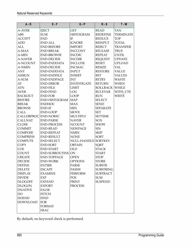
T - WR - SG - PE - FA - D
TANREADGETEJECTA-AVERTERMINATEREDEFINEHISTOGRAMELSEABSTOPREDUCEIFENDACCEPTTOTALREINPUTIGNOREEND-ALLADDTRANSFERREJECTIMPORTEND-BEFOREALLTRUERELEASEINCCONTEND-BREAKA-MAXUNTILREPEATINCDICEND-BROWSEA-MINUPDATEREQUESTINCDIREND-DECIDEA-NAVERUPLOADRESETINCLUDEEND-ENDDATAA-NCOUNTVALRESIZEINCMACEND-DECIDEA-NMINVALUERESTOREINPUTEND-ENDDATAANYVALUESRETINSERTEND-ENDFILEASSIGNWASTERETRYINTEND-ENDPAGEA-SUMWHENRETURNINVESTIGATEEND-ERRORATWHILEROLLBACKLIMITEND-FILEATNWITH_CTERULEVARLOGEND-FINDAVERWRITERUNLOOPEND-FORBACKOUT
SELECTMAPEND-HISTOGRAMBEFORESENDMAXENDHOCBREAKSEPARATEMINEND-IFBROWSESETMOVEEND-LOOPCALLSETTIMEMULTIPLYEND-NORECCALLDBPROCSGNNAVEREND-PARSECALLNATSHOWNCOUNTEND-PROCESSCLOSESINNEWPAGEEND-READCOMMITSKIPNMINEND-REPEATCOMPOSESORTNONEEND-RESULTCOMPRESSSORTKEYNULL-HANDLEEND-SELECTCOMPUTESQRTOBTAINEND-SORTCOPYSTACKOLDEND-STARTCOSSTARTONEND-SUBROUTINECOUNTSTOPOPENEND-TOPPAGECREATESTOREOPTIONSEND-WORKDECIDESUBSTRPARSEENTIREDEFINESUBSTRINGPASSWESCAPEDELETESUBTRACTPERFORMEXAMINEDISPLAYSUMPOSEXPDIVIDESUSPENDPRINTEXPANDDLOGOFF
PROCESSEXPORTDLOGONFALSEDNATIVEFETCHDOFINDDOENDFORDOWNLOADFORMATFRAC
By default, no keyword check is performed.
Programming Guide990
Natural Reserved Keywords
134 Referenced Example Programs
■ READ Statement ........................................................................................................................... 992■ FIND Statement ............................................................................................................................ 993■ Nested READ and FIND Statements ................................................................................................. 997■ ACCEPT and REJECT Statements ................................................................................................... 999■ AT START OF DATA and AT END OF DATA Statements ...................................................................... 1001■ DISPLAY and WRITE Statements ................................................................................................... 1004■ DISPLAY Statement ..................................................................................................................... 1008■ Column Headers .......................................................................................................................... 1009■ Field-Output-Relevant Parameters .................................................................................................. 1011■ Edit Masks .................................................................................................................................. 1017■ DISPLAY VERT with WRITE Statement ............................................................................................ 1020■ AT BREAK Statement ................................................................................................................... 1021■ COMPUTE, MOVE and COMPRESS Statements ............................................................................... 1022■ System Variables ......................................................................................................................... 1025■ System Functions ........................................................................................................................ 1028
991

This chapter contains some additional example programs that are referenced in the ProgrammingGuide.
READ Statement
The following example is referenced in the section Statements for Database Access.
READX03 - READ statement (with LOGICAL clause)
** Example 'READX03': READ (with LOGICAL clause)************************************************************************DEFINE DATA LOCAL1 EMPLOY-VIEW VIEW OF EMPLOYEES
2 NAME2 PERSONNEL-ID2 JOB-TITLE
END-DEFINE*LIMIT 8READ EMPLOY-VIEW LOGICAL BY PERSONNEL-ID
DISPLAY NOTITLE *ISN NAME'PERS-NO' PERSONNEL-ID'POSITION' JOB-TITLE
END-READEND
Output of Program READX03:
ISN NAME PERS-NO POSITION----------- -------------------- -------- -------------------------
204 SCHINDLER 11100102 PROGRAMMIERER205 SCHIRM 11100105 SYSTEMPROGRAMMIERER206 SCHMITT 11100106 OPERATOR207 SCHMIDT 11100107 SEKRETAERIN208 SCHNEIDER 11100108 SACHBEARBEITER209 SCHNEIDER 11100109 SEKRETAERIN210 BUNGERT 11100110 SYSTEMPROGRAMMIERER211 THIELE 11100111 SEKRETAERIN
Programming Guide992
Referenced Example Programs

FIND Statement
The following examples are referenced in the section Statements for Database Access.
FINDX07 - FIND statement (with several clauses)
** Example 'FINDX07': FIND (with several clauses)************************************************************************DEFINE DATA LOCAL1 EMPLOY-VIEW VIEW OF EMPLOYEES
2 NAME2 FIRST-NAME2 CITY2 SALARY (1)2 CURR-CODE (1)
END-DEFINE*FIND EMPLOY-VIEW WITH PHONETIC-NAME = 'JONES' OR = 'BECKR'
AND CITY = 'BOSTON' THRU 'NEW YORK'BUT NOT 'CHAPEL HILL'SORTED BY NAMEWHERE SALARY (1) < 28000
DISPLAY NOTITLE NAME FIRST-NAME CITY SALARY (1)END-FINDEND
Output of Program FINDX07:
NAME FIRST-NAME CITY ANNUALSALARY
-------------------- -------------------- -------------------- ----------
BAKER PAULINE DERBY 4450JONES MARTHA KALAMAZOO 21000JONES KEVIN DERBY 7000
FINDX08 - FIND statement (with LIMIT)
** Example 'FINDX08': FIND (with LIMIT)** Demonstrates FIND statement with LIMIT option to** terminate program with an error message if the** number of records selected exceeds a specified** limit (no output).************************************************************************DEFINE DATA LOCAL
993Programming Guide
Referenced Example Programs

1 EMPLOY-VIEW VIEW OF EMPLOYEES2 NAME2 JOB-TITLE
END-DEFINE*FIND EMPLOY-VIEW WITH LIMIT (5) JOB-TITLE = 'SALES PERSON'
DISPLAY NAME JOB-TITLEEND-FINDEND
Runtime Error Caused by Program FINDX08:
NAT1005 More records found than specified in search limit.
FINDX09 - FIND statement (using *NUMBER, *COUNTER, *ISN)
** Example 'FINDX09': FIND (using *NUMBER, *COUNTER, *ISN)************************************************************************DEFINE DATA LOCAL1 EMPLOY-VIEW VIEW OF EMPLOYEES
2 DEPT2 NAME
END-DEFINE*FIND EMPLOY-VIEW WITH CITY = 'BOSTON'
WHERE DEPT = 'TECH00' THRU 'TECH10'DISPLAY NOTITLE
'COUNTER' *COUNTER NAME DEPT 'ISN' *ISNAT START OF DATA
WRITE '(TOTAL NUMBER IN BOSTON:' *NUMBER ')' /END-START
END-FINDEND
Output of Program FINDX09:
COUNTER NAME DEPARTMENT ISNCODE
----------- -------------------- ---------- -----------
(TOTAL NUMBER IN BOSTON: 7 )
1 STANWOOD TECH10 7822 PERREAULT TECH10 842
Programming Guide994
Referenced Example Programs

FINDX10 - FIND statement (combined with READ)
** Example 'FINDX10': FIND (combined with READ)************************************************************************DEFINE DATA LOCAL1 EMPLOY-VIEW VIEW OF EMPLOYEES
2 PERSONNEL-ID2 NAME2 FIRST-NAME
1 VEHIC-VIEW VIEW OF VEHICLES2 PERSONNEL-ID2 MAKE
END-DEFINE*LIMIT 15*EMP. READ EMPLOY-VIEW BY NAME STARTING FROM 'JONES'
VEH. FIND VEHIC-VIEW WITH PERSONNEL-ID = PERSONNEL-ID (EMP.)IF NO RECORDS FOUNDMOVE '*** NO CAR ***' TO MAKE
END-NORECDISPLAY NOTITLE
NAME (EMP.) (IS=ON)FIRST-NAME (EMP.) (IS=ON)MAKE (VEH.)
END-FINDEND-READEND
Output of Program FINDX10:
NAME FIRST-NAME MAKE-------------------- -------------------- --------------------
JONES VIRGINIA CHRYSLERMARSHA CHRYSLER
CHRYSLERROBERT GENERAL MOTORSLILLY FORD
MGEDWARD GENERAL MOTORSMARTHA GENERAL MOTORSLAUREL GENERAL MOTORSKEVIN DATSUNGREGORY FORD
JOPER MANFRED *** NO CAR ***JOUSSELIN DANIEL RENAULTJUBE GABRIEL *** NO CAR ***JUNG ERNST *** NO CAR ***
995Programming Guide
Referenced Example Programs

JUNKIN JEREMY *** NO CAR ***KAISER REINER *** NO CAR ***
FINDX11 - FIND NUMBER statement (with *NUMBER)
** Example 'FINDX11': FIND NUMBER (with *NUMBER)************************************************************************DEFINE DATA LOCAL1 EMPLOY-VIEW VIEW OF EMPLOYEES
2 FIRST-NAME2 NAME2 CITY2 JOB-TITLE2 SALARY (1)
*1 #PERCENT (N.2)1 REDEFINE #PERCENT
2 #WHOLE-NBR (N2)1 #ALL-BOST (N3.2)1 #SECR-ONLY (N3.2)1 #BOST-NBR (N3)1 #SECR-NBR (N3)END-DEFINE*F1. FIND NUMBER EMPLOY-VIEW WITH CITY = 'BOSTON'F2. FIND NUMBER EMPLOY-VIEW WITH CITY = 'BOSTON'
AND JOB-TITLE = 'SECRETARY'*MOVE *NUMBER(F1.) TO #ALL-BOST #BOST-NBRMOVE *NUMBER(F2.) TO #SECR-ONLY #SECR-NBRDIVIDE #ALL-BOST INTO #SECR-ONLY GIVING #PERCENT*WRITE TITLE LEFT JUSTIFIED UNDERLINED
'There are' #BOST-NBR 'employees in the Boston offices.' /#SECR-NBR '(=' #WHOLE-NBR (EM=99%')') 'are secretaries.'
*SKIP 1FIND EMPLOY-VIEW WITH CITY = 'BOSTON'
AND JOB-TITLE = 'SECRETARY'DISPLAY NAME FIRST-NAME JOB-TITLE SALARY (1)
END-FINDEND
Output of Program FINDX11:
Programming Guide996
Referenced Example Programs

There are 7 employees in the Boston offices.3 (= 42%) are secretaries.
-------------------------------------------------------------------------------
NAME FIRST-NAME CURRENT ANNUALPOSITION SALARY
-------------------- -------------------- ------------------------- ----------
SHAW LESLIE SECRETARY 18000CREMER WALT SECRETARY 20000COHEN JOHN SECRETARY 16000
Nested READ and FIND Statements
The following examples are referenced in the section Database Processing Loops.
READX04 - READ statement (in combination with FIND and the system variables *NUMBERand *COUNTER)
** Example 'READX04': READ (in combination with FIND and the system** variables *NUMBER and *COUNTER)************************************************************************DEFINE DATA LOCAL1 EMPLOY-VIEW VIEW OF EMPLOYEES
2 PERSONNEL-ID2 NAME2 FIRST-NAME
1 VEHIC-VIEW VIEW OF VEHICLES2 PERSONNEL-ID2 MAKE
END-DEFINE*LIMIT 10RD. READ EMPLOY-VIEW BY NAME STARTING FROM 'JONES'
FD. FIND VEHIC-VIEW WITH PERSONNEL-ID = PERSONNEL-ID (RD.)IF NO RECORDS FOUNDENTER
END-NOREC/*DISPLAY NOTITLE
*COUNTER (RD.)(NL=8) NAME (AL=15) FIRST-NAME (AL=10)*NUMBER (FD.)(NL=8) *COUNTER (FD.)(NL=8) MAKE
END-FINDEND-READEND
Output of Program READX04:
997Programming Guide
Referenced Example Programs
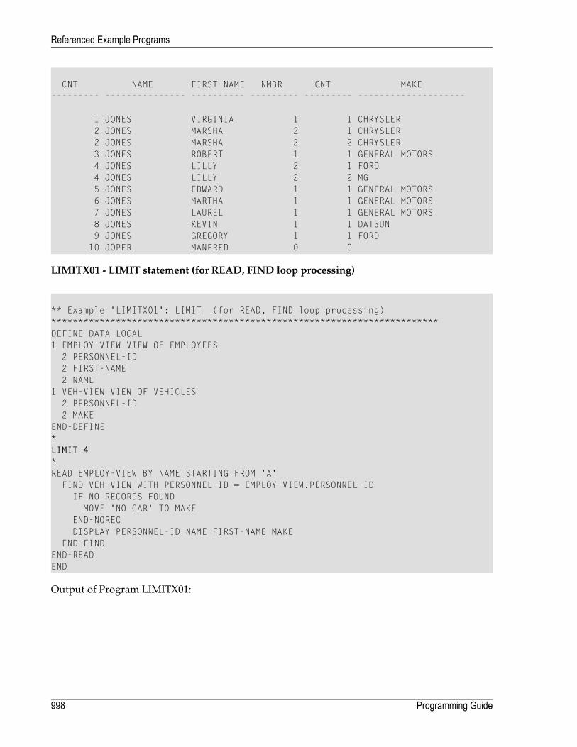
CNT NAME FIRST-NAME NMBR CNT MAKE--------- --------------- ---------- --------- --------- --------------------
1 JONES VIRGINIA 1 1 CHRYSLER2 JONES MARSHA 2 1 CHRYSLER2 JONES MARSHA 2 2 CHRYSLER3 JONES ROBERT 1 1 GENERAL MOTORS4 JONES LILLY 2 1 FORD4 JONES LILLY 2 2 MG5 JONES EDWARD 1 1 GENERAL MOTORS6 JONES MARTHA 1 1 GENERAL MOTORS7 JONES LAUREL 1 1 GENERAL MOTORS8 JONES KEVIN 1 1 DATSUN9 JONES GREGORY 1 1 FORD10 JOPER MANFRED 0 0
LIMITX01 - LIMIT statement (for READ, FIND loop processing)
** Example 'LIMITX01': LIMIT (for READ, FIND loop processing)************************************************************************DEFINE DATA LOCAL1 EMPLOY-VIEW VIEW OF EMPLOYEES
2 PERSONNEL-ID2 FIRST-NAME2 NAME
1 VEH-VIEW VIEW OF VEHICLES2 PERSONNEL-ID2 MAKE
END-DEFINE*LIMIT 4*READ EMPLOY-VIEW BY NAME STARTING FROM 'A'
FIND VEH-VIEW WITH PERSONNEL-ID = EMPLOY-VIEW.PERSONNEL-IDIF NO RECORDS FOUNDMOVE 'NO CAR' TO MAKE
END-NORECDISPLAY PERSONNEL-ID NAME FIRST-NAME MAKE
END-FINDEND-READEND
Output of Program LIMITX01:
Programming Guide998
Referenced Example Programs
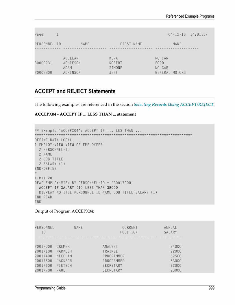
Page 1 04-12-13 14:01:57
PERSONNEL-ID NAME FIRST-NAME MAKE------------ -------------------- -------------------- --------------------
ABELLAN KEPA NO CAR30000231 ACHIESON ROBERT FORD
ADAM SIMONE NO CAR20008800 ADKINSON JEFF GENERAL MOTORS
ACCEPT and REJECT Statements
The following examples are referenced in the section Selecting Records Using ACCEPT/REJECT.
ACCEPX04 - ACCEPT IF ... LESS THAN ... statement
** Example 'ACCEPX04': ACCEPT IF ... LES THAN ...************************************************************************DEFINE DATA LOCAL1 EMPLOY-VIEW VIEW OF EMPLOYEES
2 PERSONNEL-ID2 NAME2 JOB-TITLE2 SALARY (1)
END-DEFINE*LIMIT 20READ EMPLOY-VIEW BY PERSONNEL-ID = '20017000'
ACCEPT IF SALARY (1) LESS THAN 38000DISPLAY NOTITLE PERSONNEL-ID NAME JOB-TITLE SALARY (1)
END-READEND
Output of Program ACCEPX04:
PERSONNEL NAME CURRENT ANNUALID POSITION SALARY
--------- -------------------- ------------------------- ----------
20017000 CREMER ANALYST 3400020017100 MARKUSH TRAINEE 2200020017400 NEEDHAM PROGRAMMER 3250020017500 JACKSON PROGRAMMER 3300020017600 PIETSCH SECRETARY 2200020017700 PAUL SECRETARY 23000
999Programming Guide
Referenced Example Programs

20018000 FARRIS PROGRAMMER 3050020018100 EVANS PROGRAMMER 3100020018200 HERZOG PROGRAMMER 3150020018300 LORIE SALES PERSON 2800020018400 HALL SALES PERSON 3000020018500 JACKSON MANAGER 3600020018800 SMITH SECRETARY 2400020018900 LOWRY SECRETARY 25000
ACCEPX05 - ACCEPT IF ... AND ... statement
** Example 'ACCEPX05': ACCEPT IF ... AND ...************************************************************************DEFINE DATA LOCAL1 EMPLOY-VIEW VIEW OF EMPLOYEES
2 NAME2 CITY2 JOB-TITLE2 SALARY (1:2)
END-DEFINE*LIMIT 6READ EMPLOY-VIEW PHYSICAL WHERE SALARY(2) > 0
ACCEPT IF SALARY(1) > 10000AND SALARY(1) < 50000
DISPLAY (AL=15) 'SALARY I' SALARY (1) 'SALARY II' SALARY (2)NAME JOB-TITLE CITY
END-READEND
Output of Program ACCEPX05:
Page 1 04-12-13 14:05:28
SALARY I SALARY II NAME CURRENT CITYPOSITION
---------- ---------- --------------- --------------- ---------------
48000 46000 SPENGLER SACHBEARBEITER DARMSTADT45000 40000 SPECK SACHBEARBEITER DARMSTADT48000 46000 SCHINDLER PROGRAMMIERER HEPPENHEIM36000 32000 SCHMIDT SEKRETAERIN HEPPENHEIM
Programming Guide1000
Referenced Example Programs

ACCEPX06 - REJECT IF ... OR ... statement
** Example 'ACCEPX06': REJECT IF ... OR ...************************************************************************DEFINE DATA LOCAL1 EMPLOY-VIEW VIEW OF EMPLOYEES
2 PERSONNEL-ID2 SALARY (1)2 JOB-TITLE2 CITY2 NAME
END-DEFINE*LIMIT 20READ EMPLOY-VIEW LOGICAL BY PERSONNEL-ID = '20017000'
REJECT IF SALARY (1) < 20000OR SALARY (1) > 26000
DISPLAY NOTITLE SALARY (1) NAME JOB-TITLE CITYEND-READEND
Output of Program ACCEPX06:
ANNUAL NAME CURRENT CITYSALARY POSITION
---------- -------------------- ------------------------- --------------------
22000 MARKUSH TRAINEE LOS ANGELES22000 PIETSCH SECRETARY VISTA23000 PAUL SECRETARY NORFOLK24000 SMITH SECRETARY SILVER SPRING25000 LOWRY SECRETARY LEXINGTON
AT START OF DATA and AT END OF DATA Statements
The following examples are referenced in the section AT START/END OF DATA Statements.
1001Programming Guide
Referenced Example Programs
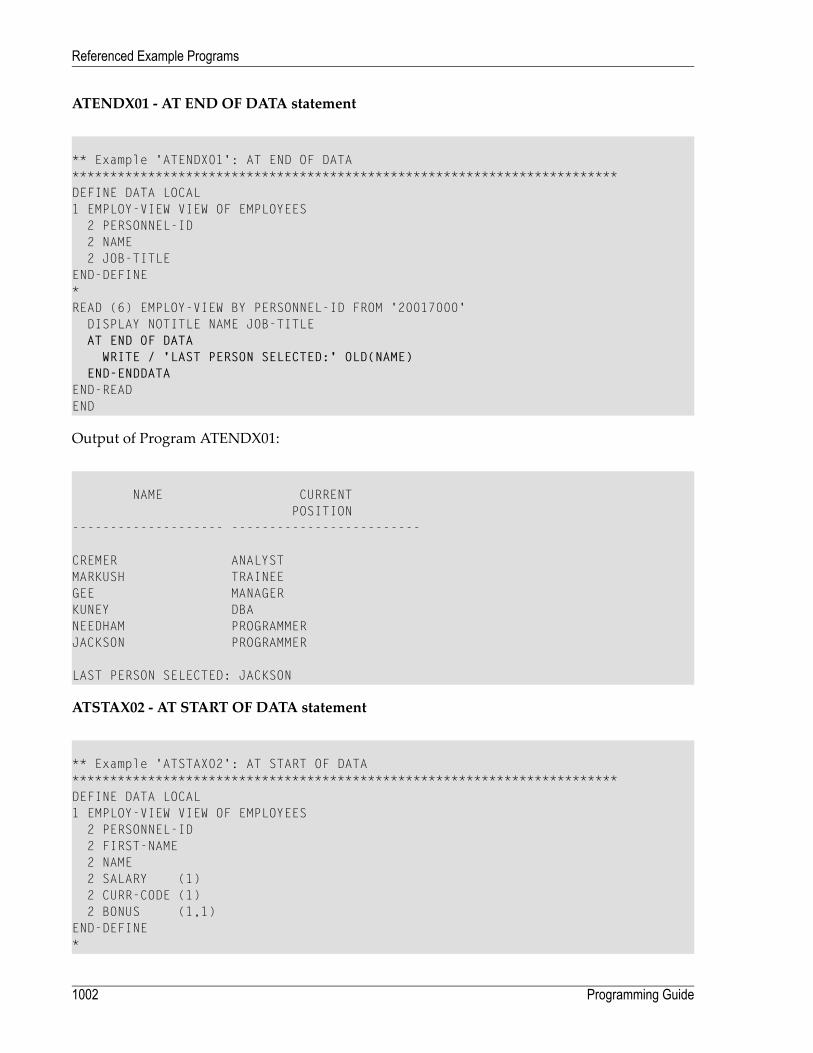
ATENDX01 - AT END OF DATA statement
** Example 'ATENDX01': AT END OF DATA************************************************************************DEFINE DATA LOCAL1 EMPLOY-VIEW VIEW OF EMPLOYEES
2 PERSONNEL-ID2 NAME2 JOB-TITLE
END-DEFINE*READ (6) EMPLOY-VIEW BY PERSONNEL-ID FROM '20017000'
DISPLAY NOTITLE NAME JOB-TITLEAT END OF DATA
WRITE / 'LAST PERSON SELECTED:' OLD(NAME)END-ENDDATA
END-READEND
Output of Program ATENDX01:
NAME CURRENTPOSITION
-------------------- -------------------------
CREMER ANALYSTMARKUSH TRAINEEGEE MANAGERKUNEY DBANEEDHAM PROGRAMMERJACKSON PROGRAMMER
LAST PERSON SELECTED: JACKSON
ATSTAX02 - AT START OF DATA statement
** Example 'ATSTAX02': AT START OF DATA************************************************************************DEFINE DATA LOCAL1 EMPLOY-VIEW VIEW OF EMPLOYEES
2 PERSONNEL-ID2 FIRST-NAME2 NAME2 SALARY (1)2 CURR-CODE (1)2 BONUS (1,1)
END-DEFINE*
Programming Guide1002
Referenced Example Programs
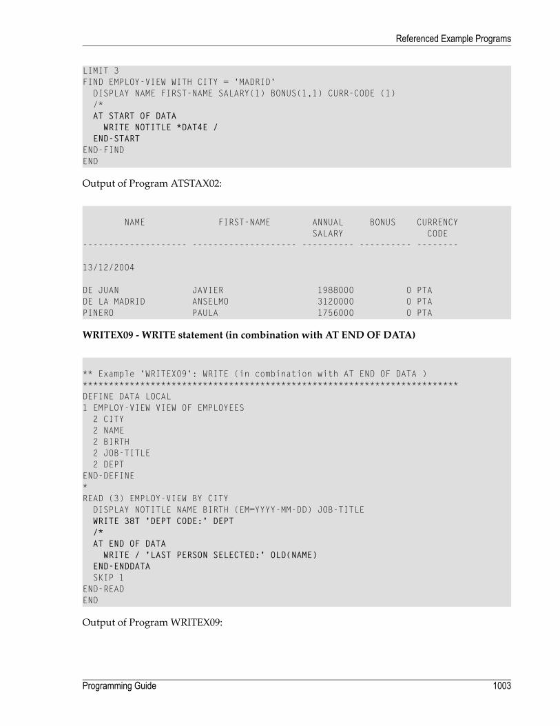
LIMIT 3FIND EMPLOY-VIEW WITH CITY = 'MADRID'
DISPLAY NAME FIRST-NAME SALARY(1) BONUS(1,1) CURR-CODE (1)/*AT START OF DATA
WRITE NOTITLE *DAT4E /END-START
END-FINDEND
Output of Program ATSTAX02:
NAME FIRST-NAME ANNUAL BONUS CURRENCYSALARY CODE
-------------------- -------------------- ---------- ---------- --------
13/12/2004
DE JUAN JAVIER 1988000 0 PTADE LA MADRID ANSELMO 3120000 0 PTAPINERO PAULA 1756000 0 PTA
WRITEX09 - WRITE statement (in combination with AT END OF DATA)
** Example 'WRITEX09': WRITE (in combination with AT END OF DATA )************************************************************************DEFINE DATA LOCAL1 EMPLOY-VIEW VIEW OF EMPLOYEES
2 CITY2 NAME2 BIRTH2 JOB-TITLE2 DEPT
END-DEFINE*READ (3) EMPLOY-VIEW BY CITY
DISPLAY NOTITLE NAME BIRTH (EM=YYYY-MM-DD) JOB-TITLEWRITE 38T 'DEPT CODE:' DEPT/*AT END OF DATA
WRITE / 'LAST PERSON SELECTED:' OLD(NAME)END-ENDDATASKIP 1
END-READEND
Output of ProgramWRITEX09:
1003Programming Guide
Referenced Example Programs

NAME DATE CURRENTOF POSITION
BIRTH-------------------- ---------- -------------------------
SENKO 1971-09-11 PROGRAMMERDEPT CODE: TECH10
GODEFROY 1949-01-09 COMPTABLEDEPT CODE: COMP02
CANALE 1942-01-01 CONSULTANTDEPT CODE: TECH03
LAST PERSON SELECTED: CANALE
DISPLAY and WRITE Statements
The following examples are referenced in the section Statements DISPLAY and WRITE.
DISPLX13 - DISPLAY statement (compare with WRITEX08 using WRITE)
** Example 'DISPLX13': DISPLAY (compare with WRITEX08 using WRITE)************************************************************************DEFINE DATA LOCAL1 EMPLOY-VIEW VIEW OF EMPLOYEES
2 PERSONNEL-ID2 FIRST-NAME2 NAME2 SALARY (2)2 BONUS (1,1)2 CITY
END-DEFINE*LIMIT 2READ EMPLOY-VIEW WITH CITY = 'CHAPEL HILL' WHERE BONUS(1,1) NE 0
/*DISPLAY 'PERS/ID' PERSONNEL-ID NAME / FIRST-NAME
'**' '=' SALARY(1:2) 'BONUS' BONUS(1,1) CITY (AL=15)/*SKIP 1
END-READEND
Output of Program DISPLX13:
Programming Guide1004
Referenced Example Programs

Page 1 04-12-13 14:11:28
PERS NAME ANNUAL BONUS CITYID FIRST-NAME SALARY
-------- -------------------- ------------- ---------- ---------------
20027000 CUMMINGS ** 41000 1500 CHAPEL HILLPUALA 38900
20000200 WOOLSEY ** 26000 3000 CHAPEL HILLLOUISE 24700
WRITEX08 - WRITE statement (compare with DISPLX13 using DISPLAY)
** Example 'WRITEX08': WRITE (compare with DISPLX13 using DISPLAY)************************************************************************DEFINE DATA LOCAL1 EMPLOY-VIEW VIEW OF EMPLOYEES
2 PERSONNEL-ID2 FIRST-NAME2 NAME2 SALARY (2)2 BONUS (1,1)2 CITY
END-DEFINE*LIMIT 2READ EMPLOY-VIEW WITH CITY = 'CHAPEL HILL' WHERE BONUS(1,1) NE 0
/*WRITE 'PERS/ID' PERSONNEL-ID NAME / FIRST-NAME
'**' '=' SALARY(1:2) 'BONUS' BONUS(1,1) CITY (AL=15)/*SKIP 1
END-READEND
Output of ProgramWRITEX08:
Page 1 04-12-13 14:12:43
PERS/ID 20027000 CUMMINGSPUALA ** ANNUAL SALARY: 41000 38900 BONUS 1500CHAPEL HILL
PERS/ID 20000200 WOOLSEYLOUISE ** ANNUAL SALARY: 26000 24700 BONUS 3000CHAPEL HILL
1005Programming Guide
Referenced Example Programs

DISPLX14 - DISPLAY statement (with AL, SF and nX)
** Example 'DISPLX14': DISPLAY (with AL, SF and nX)************************************************************************DEFINE DATA LOCAL1 EMPLOY-VIEW VIEW OF EMPLOYEES
2 FIRST-NAME2 NAME2 ADDRESS-LINE (1)2 TELEPHONE
3 AREA-CODE3 PHONE
2 CITYEND-DEFINE*READ (3) EMPLOY-VIEW BY NAME STARTING FROM 'W'
DISPLAY (AL=15 SF=5) NAME CITY / ADDRESS-LINE(1) 2X TELEPHONESKIP 1
END-READEND
Output of Program DISPLX14:
Page 1 04-12-13 14:14:00
NAME CITY TELEPHONEADDRESS
AREA TELEPHONECODE
--------------- --------------- --------------- ---------------
WABER HEIDELBERG 06221 456452ERBACHERSTR. 78
WADSWORTH DERBY 0332 51536556 PINECROFT CO
WAGENBACH FRANKFURT 069 983218BECKERSTR. 4
Programming Guide1006
Referenced Example Programs

WRITEX09 - WRITE statement (in combination with AT END OF DATA)
** Example 'WRITEX09': WRITE (in combination with AT END OF DATA )************************************************************************DEFINE DATA LOCAL1 EMPLOY-VIEW VIEW OF EMPLOYEES
2 CITY2 NAME2 BIRTH2 JOB-TITLE2 DEPT
END-DEFINE*READ (3) EMPLOY-VIEW BY CITY
DISPLAY NOTITLE NAME BIRTH (EM=YYYY-MM-DD) JOB-TITLEWRITE 38T 'DEPT CODE:' DEPT/*AT END OF DATA
WRITE / 'LAST PERSON SELECTED:' OLD(NAME)END-ENDDATASKIP 1
END-READEND
Output of ProgramWRITEX09:
NAME DATE CURRENTOF POSITION
BIRTH-------------------- ---------- -------------------------
SENKO 1971-09-11 PROGRAMMERDEPT CODE: TECH10
GODEFROY 1949-01-09 COMPTABLEDEPT CODE: COMP02
CANALE 1942-01-01 CONSULTANTDEPT CODE: TECH03
LAST PERSON SELECTED: CANALE
1007Programming Guide
Referenced Example Programs
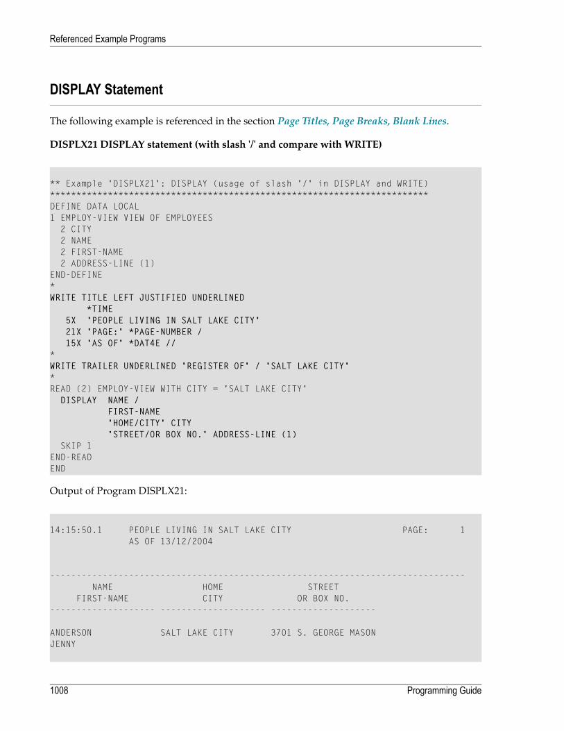
DISPLAY Statement
The following example is referenced in the section Page Titles, Page Breaks, Blank Lines.
DISPLX21 DISPLAY statement (with slash '/' and compare with WRITE)
** Example 'DISPLX21': DISPLAY (usage of slash '/' in DISPLAY and WRITE)************************************************************************DEFINE DATA LOCAL1 EMPLOY-VIEW VIEW OF EMPLOYEES
2 CITY2 NAME2 FIRST-NAME2 ADDRESS-LINE (1)
END-DEFINE*WRITE TITLE LEFT JUSTIFIED UNDERLINED
*TIME5X 'PEOPLE LIVING IN SALT LAKE CITY'21X 'PAGE:' *PAGE-NUMBER /15X 'AS OF' *DAT4E //
*WRITE TRAILER UNDERLINED 'REGISTER OF' / 'SALT LAKE CITY'*READ (2) EMPLOY-VIEW WITH CITY = 'SALT LAKE CITY'
DISPLAY NAME /FIRST-NAME'HOME/CITY' CITY'STREET/OR BOX NO.' ADDRESS-LINE (1)
SKIP 1END-READEND
Output of Program DISPLX21:
14:15:50.1 PEOPLE LIVING IN SALT LAKE CITY PAGE: 1AS OF 13/12/2004
-------------------------------------------------------------------------------NAME HOME STREET
FIRST-NAME CITY OR BOX NO.-------------------- -------------------- --------------------
ANDERSON SALT LAKE CITY 3701 S. GEORGE MASONJENNY
Programming Guide1008
Referenced Example Programs

SAMUELSON SALT LAKE CITY 7610 W. 86TH STREETMARTIN
REGISTER OFSALT LAKE CITY
-------------------------------------------------------------------------------
Column Headers
The following example is referenced in the section Column Headers.
DISPLX15 - DISPLAY statement (with FC, UC)
** Example 'DISPLX15': DISPLAY (with FC, UC)************************************************************************DEFINE DATA LOCAL1 EMPLOY-VIEW VIEW OF EMPLOYEES
2 FIRST-NAME2 NAME2 ADDRESS-LINE (1)2 CITY2 TELEPHONE
3 AREA-CODE3 PHONE
END-DEFINE*FORMAT AL=12 GC== UC=%*READ (3) EMPLOY-VIEW BY NAME STARTING FROM 'R'
DISPLAY NOTITLE (FC=*)NAME FIRST-NAME CITY (FC=- UC=-) /ADDRESS-LINE(1) TELEPHONE
SKIP 1END-READEND
Output of Program DISPLX15:
****NAME**** *FIRST-NAME* ----CITY---- ========TELEPHONE========**ADDRESS***
****AREA**** *TELEPHONE******CODE****
%%%%%%%%%%%% %%%%%%%%%%%% ------------ %%%%%%%%%%%% %%%%%%%%%%%%
RACKMANN MARIAN FRANKFURT 069 375849FINKENSTR. 1
1009Programming Guide
Referenced Example Programs
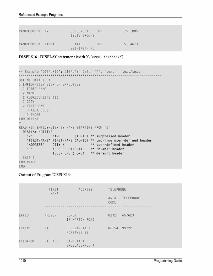
RAMAMOORTHY TY SEPULVEDA 209 175-188512018 BROOKS
RAMAMOORTHY TIMMIE SEATTLE 206 151-4673921-178TH PL
DISPLX16 - DISPLAY statement (with '/', 'text', 'text/text')
** Example 'DISPLX16': DISPLAY (with '/', 'text', 'text/text')************************************************************************DEFINE DATA LOCAL1 EMPLOY-VIEW VIEW OF EMPLOYEES
2 FIRST-NAME2 NAME2 ADDRESS-LINE (1)2 CITY2 TELEPHONE
3 AREA-CODE3 PHONE
END-DEFINE*READ (5) EMPLOY-VIEW BY NAME STARTING FROM 'E'
DISPLAY NOTITLE'/' NAME (AL=12) /* suppressed header'FIRST/NAME' FIRST-NAME (AL=10) /* two-line user-defined header'ADDRESS' CITY / /* user-defined header' ' ADDRESS-LINE(1) /* 'blank' header
TELEPHONE (HC=L) /* default headerSKIP 1
END-READEND
Output of Program DISPLX16:
FIRST ADDRESS TELEPHONENAME
AREA TELEPHONECODE
---------- -------------------- ------ ---------------
EAVES TREVOR DERBY 0332 65762317 HARTON ROAD
ECKERT KARL OBERRAMSTADT 06154 99722FORSTWEG 22
ECKHARDT RICHARD DARMSTADTBRESLAUERPL. 4
Programming Guide1010
Referenced Example Programs

EDMUNDSON LES TULSA 918 945-49162415 ALSOP CT.
EGGERT HERMANN STUTTGART 0711 981237RABENGASSE 8
Field-Output-Relevant Parameters
The following examples are referenced in the sectionParameters to Influence theOutput of Fields.
They are provided to demonstrate the use of the parameters LC, IC, TC, AL, NL, IS, ZP and ES, andthe SUSPEND IDENTICAL SUPPRESS statement:
DISPLX17 - DISPLAY statement (with NL, AL, IC, LC, TC)
** Example 'DISPLX17': DISPLAY (with NL, AL, IC, LC, TC)************************************************************************DEFINE DATA LOCAL1 EMPLOY-VIEW VIEW OF EMPLOYEES
2 FIRST-NAME2 NAME2 SALARY (1)2 BONUS (1,1)
END-DEFINE*READ (3) EMPLOY-VIEW BY NAME STARTING FROM 'JONES'
DISPLAY NOTITLE (IS=ON NL=15)NAME
'-' '=' FIRST-NAME (AL=12)'ANNUAL SALARY' SALARY(1) (LC=USD TC=.00) /'+ BONUSES' BONUS(1,1) (IC='+ ' TC=.00)
SKIP 1END-READEND
Output of Program DISPLX17:
NAME FIRST-NAME ANNUAL SALARY+ BONUSES
-------------------- -------------- ----------------------
JONES - VIRGINIA USD 46000.00+ 9000.00
- MARSHA USD 50000.00
1011Programming Guide
Referenced Example Programs

+ 0.00
- ROBERT USD 31000.00+ 0.00
DISPLX18 - DISPLAY statement (using default settings for SF, AL, UC, LC, IC, TC and comparewith DISPLX19)
** Example 'DISPLX18': DISPLAY (using default settings for SF, AL, UC,** LC, IC, TC and compare with DISPLX19)************************************************************************DEFINE DATA LOCAL1 EMPLOY-VIEW VIEW OF EMPLOYEES
2 NAME2 FIRST-NAME2 CITY2 SALARY (1)2 BONUS (1,1)
END-DEFINE*FIND (6) EMPLOY-VIEW WITH CITY = 'CHAPEL HILL'
DISPLAY NAME FIRST-NAME SALARY(1) BONUS(1,1)END-FINDEND
Output of Program DISPLX18:
Page 1 04-12-13 14:20:48
NAME FIRST-NAME ANNUAL BONUSSALARY
-------------------- -------------------- ---------- ----------
KESSLER CLARE 41000 0ADKINSON DAVID 24000 0GEE TOMMIE 39500 0HERZOG JOHN 31500 0QUILLION TIMOTHY 30500 0CUMMINGS PUALA 41000 1500
Programming Guide1012
Referenced Example Programs

DISPLX19 - DISPLAY statement (with SF, AL, LC, IC, TC and compare with DISPLX18)
** Example 'DISPLX19': DISPLAY (with SF, AL, LC, IC, TC and compare** with DISPLX19)************************************************************************DEFINE DATA LOCAL1 EMPLOY-VIEW VIEW OF EMPLOYEES
2 NAME2 FIRST-NAME2 CITY2 SALARY (1)2 BONUS (1,1)
END-DEFINE*FORMAT SF=3 AL=15 UC==*FIND (6) EMPLOY-VIEW WITH CITY = 'CHAPEL HILL'
DISPLAY (NL=10)NAMEFIRST-NAME (LC='- ' UC=-)SALARY (1) (LC=USD)BONUS (1,1) (IC='*** ' TC=' ***')
END-FINDEND
Output of Program DISPLX19:
Page 1 04-12-13 14:21:57
NAME FIRST-NAME ANNUAL BONUSSALARY
=============== ----------------- ============== ===================
KESSLER - CLARE USD 41000 *** 0 ***ADKINSON - DAVID USD 24000 *** 0 ***GEE - TOMMIE USD 39500 *** 0 ***HERZOG - JOHN USD 31500 *** 0 ***QUILLION - TIMOTHY USD 30500 *** 0 ***CUMMINGS - PUALA USD 41000 *** 1500 ***
1013Programming Guide
Referenced Example Programs

SUSPEX01 - SUSPEND IDENTICALSUPPRESS statement (in conjunctionwith parameters IS,ES, ZP in DISPLAY)
** Example 'SUSPEX01': SUSPEND IDENTICAL SUPPRESS (in conjunction with** parameters IS, ES, ZP in DISPLAY)************************************************************************DEFINE DATA LOCAL1 EMPLOY-VIEW VIEW OF EMPLOYEES
2 PERSONNEL-ID2 FIRST-NAME2 NAME2 CITY
1 VEH-VIEW VIEW OF VEHICLES2 PERSONNEL-ID2 MAKE
END-DEFINE*LIMIT 15RD. READ EMPLOY-VIEW BY NAME STARTING FROM 'JONES'
SUSPEND IDENTICAL SUPPRESSFD. FIND VEH-VIEW WITH PERSONNEL-ID = PERSONNEL-ID (RD.)
IF NO RECORDS FOUNDMOVE '******' TO MAKE
END-NORECDISPLAY NOTITLE (ES=OFF IS=ON ZP=ON AL=15)
NAME (RD.)FIRST-NAME (RD.)MAKE (FD.) (IS=OFF)
END-FINDEND-READEND
Output of Program SUSPEX01:
NAME FIRST-NAME MAKE--------------- --------------- ---------------
JONES VIRGINIA CHRYSLERJONES MARSHA CHRYSLER
CHRYSLERJONES ROBERT GENERAL MOTORSJONES LILLY FORD
MGJONES EDWARD GENERAL MOTORSJONES MARTHA GENERAL MOTORSJONES LAUREL GENERAL MOTORSJONES KEVIN DATSUNJONES GREGORY FORDJOPER MANFRED ******
Programming Guide1014
Referenced Example Programs

JOUSSELIN DANIEL RENAULTJUBE GABRIEL ******JUNG ERNST ******JUNKIN JEREMY ******KAISER REINER ******
SUSPEX02 - SUSPEND IDENTICALSUPPRESS statement (in conjunctionwith parameters IS,ES, ZP in DISPLAY) Identical to SUSPEX01, but with IS=OFF.
** Example 'SUSPEX02': SUSPEND IDENTICAL SUPPRESS (in conjunction with** parameters IS, ES, ZP in DISPLAY)** Identical to SUSPEX01, but with IS=OFF.************************************************************************DEFINE DATA LOCAL1 EMPLOY-VIEW VIEW OF EMPLOYEES
2 PERSONNEL-ID2 FIRST-NAME2 NAME2 CITY
1 VEH-VIEW VIEW OF VEHICLES2 PERSONNEL-ID2 MAKE
END-DEFINE*LIMIT 15RD. READ EMPLOY-VIEW BY NAME STARTING FROM 'JONES'
SUSPEND IDENTICAL SUPPRESSFD. FIND VEH-VIEW WITH PERSONNEL-ID = PERSONNEL-ID (RD.)
IF NO RECORDS FOUNDMOVE '******' TO MAKE
END-NORECDISPLAY NOTITLE (ES=OFF IS=OFF ZP=ON AL=15)
NAME (RD.)FIRST-NAME (RD.)MAKE (FD.) (IS=OFF)
END-FINDEND-READEND
Output of Program SUSPEX02:
NAME FIRST-NAME MAKE--------------- --------------- ---------------
JONES VIRGINIA CHRYSLERJONES MARSHA CHRYSLERJONES MARSHA CHRYSLERJONES ROBERT GENERAL MOTORSJONES LILLY FORD
1015Programming Guide
Referenced Example Programs

JONES LILLY MGJONES EDWARD GENERAL MOTORSJONES MARTHA GENERAL MOTORSJONES LAUREL GENERAL MOTORSJONES KEVIN DATSUNJONES GREGORY FORDJOPER MANFRED ******JOUSSELIN DANIEL RENAULTJUBE GABRIEL ******JUNG ERNST ******JUNKIN JEREMY ******KAISER REINER ******
COMPRX03 - COMPRESS statement
** Example 'COMPRX03': COMPRESS (using parameters LC and TC)************************************************************************DEFINE DATA LOCAL1 EMPLOY-VIEW VIEW OF EMPLOYEES
2 CITY2 SALARY (1)2 CURR-CODE (1)2 LEAVE-DUE2 NAME2 FIRST-NAME2 JOB-TITLE
*1 #SALARY (N9)1 #FULL-SALARY (A25)1 #VACATION (A11)END-DEFINE*READ (3) EMPLOY-VIEW WITH CITY = 'BOSTON'
MOVE SALARY(1) TO #SALARYCOMPRESS 'SALARY :' CURR-CODE(1) #SALARY INTO #FULL-SALARYCOMPRESS 'VACATION:' LEAVE-DUE INTO #VACATION/*DISPLAY NOTITLE NAME FIRST-NAME
'JOB DESCRIPTION' JOB-TITLE (LC='JOB : ') /'/' #FULL-SALARY /'/' #VACATION (TC='DAYS')
SKIP 1END-READEND
Output of Program COMPRX03:
Programming Guide1016
Referenced Example Programs
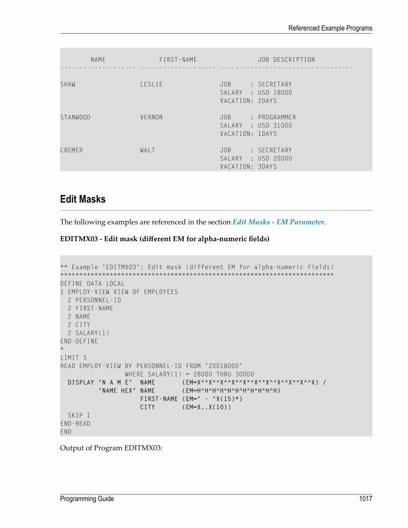
NAME FIRST-NAME JOB DESCRIPTION-------------------- -------------------- -----------------------------------
SHAW LESLIE JOB : SECRETARYSALARY : USD 18000VACATION: 2DAYS
STANWOOD VERNON JOB : PROGRAMMERSALARY : USD 31000VACATION: 1DAYS
CREMER WALT JOB : SECRETARYSALARY : USD 20000VACATION: 3DAYS
Edit Masks
The following examples are referenced in the section Edit Masks - EM Parameter.
EDITMX03 - Edit mask (different EM for alpha-numeric fields)
** Example 'EDITMX03': Edit mask (different EM for alpha-numeric fields)************************************************************************DEFINE DATA LOCAL1 EMPLOY-VIEW VIEW OF EMPLOYEES
2 PERSONNEL-ID2 FIRST-NAME2 NAME2 CITY2 SALARY(1)
END-DEFINE*LIMIT 3READ EMPLOY-VIEW BY PERSONNEL-ID FROM '20018000'
WHERE SALARY(1) = 28000 THRU 30000DISPLAY 'N A M E' NAME (EM=X^^X^^X^^X^^X^^X^^X^^X^^X^^X^^X) /
'NAME HEX' NAME (EM=H^H^H^H^H^H^H^H^H^H^H)FIRST-NAME (EM=' - 'X(15)*)CITY (EM=X..X(10))
SKIP 1END-READEND
Output of Program EDITMX03:
1017Programming Guide
Referenced Example Programs

Page 1 04-12-13 14:26:57
N A M E FIRST-NAME CITYNAME HEX
-------------------------------- ------------------ -------------
L O R I E - JEAN-PAUL * C..LEVELANDD3 D6 D9 C9 C5 40 40 40 40 40 40
H A L L - ARTHUR * A..NN ARBERC8 C1 D3 D3 40 40 40 40 40 40 40
V A S W A N I - TOMMIE * M..ONTERREYE5 C1 E2 E6 C1 D5 C9 40 40 40 40
EDITMX04 - Edit mask (different EM for numeric fields)
** Example 'EDITMX04': Edit mask (different EM for numeric fields)************************************************************************DEFINE DATA LOCAL1 EMPLOY-VIEW VIEW OF EMPLOYEES
2 PERSONNEL-ID2 FIRST-NAME2 NAME2 SALARY (1)2 BONUS (1,1)2 LEAVE-DUE
END-DEFINE*LIMIT 2READ EMPLOY-VIEW BY PERSONNEL-ID = '20018000'
WHERE SALARY(1) = 28000 THRU 30000DISPLAY (SF=4)
'N A M E' NAME'SALARY' SALARY(1) (EM=*USD^ZZZ,999)'BONUS (ZZ)' BONUS(1,1) (EM=S*ZZZ,999) /'BONUS (Z9)' BONUS(1,1) (EM=SZ99,999+) /'->' '=' BONUS(1,1) (EM=-999,999)'VAC/DUE' LEAVE-DUE (EM=+999)
SKIP 1END-READEND
Output of Program EDITMX04:
Programming Guide1018
Referenced Example Programs

Page 1 04-12-13 14:27:43
N A M E SALARY BONUS (ZZ) VACBONUS (Z9) DUE
BONUS-------------------- ----------- ----------- ---
LORIE USD *28,000 +**4,000 +13+ 04,000+-> 004,000
HALL USD *30,000 +**5,000 +14+ 05,000+-> 005,000
EDITMX05 - Edit mask (EM for date and time system variables)
** Example 'EDITMX05': Edit mask (EM for date and time system variables)************************************************************************WRITE NOTITLE //
'DATE INTERNAL :' *DATX (DF=L) /' :' *DATX (EM=N(9)' 'ZW.'WEEK 'YYYY) /' :' *DATX (EM=ZZJ'.DAY 'YYYY) /' ROMAN :' *DATX (EM=R) /' AMERICAN :' *DATX (EM=MM/DD/YYYY) 12X 'OR ' *DAT4U /' JULIAN :' *DATX (EM=YYYYJJJ) 15X 'OR ' *DAT4J /' GREGORIAN:' *DATX (EM=ZD.''L(10)''YYYY) 5X 'OR ' *DATG ///'TIME INTERNAL :' *TIMX 14X 'OR ' *TIME /' :' *TIMX (EM=HH.II.SS.T) /' :' *TIMX (EM=HH.II.SS' 'AP) /' :' *TIMX (EM=HH)
END
Output of Program EDITMX05:
DATE INTERNAL : 2004-12-13: Monday 51.WEEK 2004: 348.DAY 2004
ROMAN : MMIVAMERICAN : 12/13/2004 OR 12/13/2004JULIAN : 2004348 OR 2004348GREGORIAN: 13.December2004 OR 13December 2004
TIME INTERNAL : 14:28:49 OR 14:28:49.1: 14.28.49.1
1019Programming Guide
Referenced Example Programs

: 02.28.49 PM: 14
DISPLAY VERT with WRITE Statement
WRITEX10 - WRITE statement (with nT, T*field and P*field)
** Example 'WRITEX10': WRITE (with nT, T*field and P*field)************************************************************************DEFINE DATA LOCAL1 EMPLOY-VIEW VIEW OF EMPLOYEES
2 JOB-TITLE2 NAME2 SALARY (1)2 BONUS (1,1)
END-DEFINE*READ (3) EMPLOY-VIEW WITH JOB-TITLE FROM 'SALES PERSON'
DISPLAY NOTITLE NAME 30T JOB-TITLEVERT AS 'SALARY/BONUS' SALARY(1) BONUS(1,1)
AT BREAK OF JOB-TITLEWRITE 20T 'AVERAGE' T*JOB-TITLE OLD(JOB-TITLE) (AL=15)
'(SAL)' P*SALARY AVER(SALARY(1)) /46T '(BON)' P*BONUS AVER(BONUS(1,1)) /
END-BREAKSKIP 1
END-READEND
Output of ProgramWRITEX10:
NAME CURRENT SALARYPOSITION BONUS
-------------------- ------------------------- ----------
SAMUELSON SALES PERSON 320006000
PAPAYANOPOULOS SALES PERSON 340007000
HELL SALES PERSON 380009000
AVERAGE SALES PERSON (SAL) 34666(BON) 7333
Programming Guide1020
Referenced Example Programs
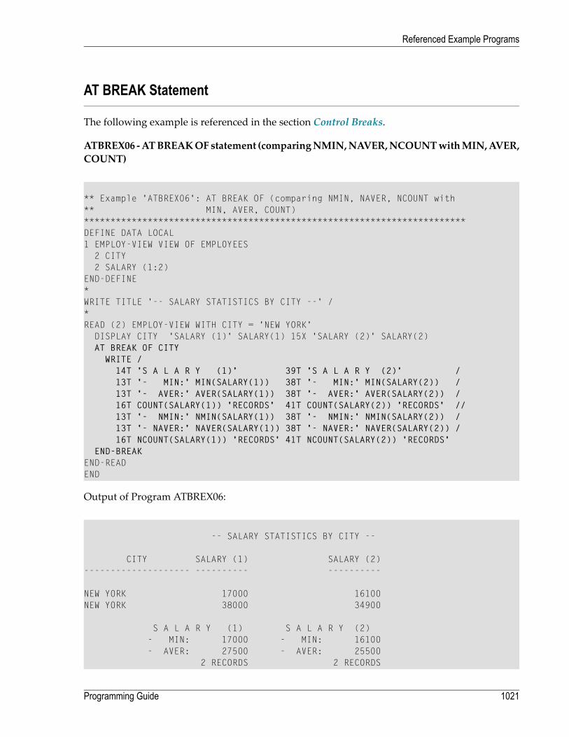
AT BREAK Statement
The following example is referenced in the section Control Breaks.
ATBREX06 -ATBREAKOFstatement (comparingNMIN,NAVER,NCOUNTwithMIN,AVER,COUNT)
** Example 'ATBREX06': AT BREAK OF (comparing NMIN, NAVER, NCOUNT with** MIN, AVER, COUNT)************************************************************************DEFINE DATA LOCAL1 EMPLOY-VIEW VIEW OF EMPLOYEES
2 CITY2 SALARY (1:2)
END-DEFINE*WRITE TITLE '-- SALARY STATISTICS BY CITY --' /*READ (2) EMPLOY-VIEW WITH CITY = 'NEW YORK'
DISPLAY CITY 'SALARY (1)' SALARY(1) 15X 'SALARY (2)' SALARY(2)AT BREAK OF CITY
WRITE /14T 'S A L A R Y (1)' 39T 'S A L A R Y (2)' /13T '- MIN:' MIN(SALARY(1)) 38T '- MIN:' MIN(SALARY(2)) /13T '- AVER:' AVER(SALARY(1)) 38T '- AVER:' AVER(SALARY(2)) /16T COUNT(SALARY(1)) 'RECORDS' 41T COUNT(SALARY(2)) 'RECORDS' //13T '- NMIN:' NMIN(SALARY(1)) 38T '- NMIN:' NMIN(SALARY(2)) /13T '- NAVER:' NAVER(SALARY(1)) 38T '- NAVER:' NAVER(SALARY(2)) /16T NCOUNT(SALARY(1)) 'RECORDS' 41T NCOUNT(SALARY(2)) 'RECORDS'
END-BREAKEND-READEND
Output of Program ATBREX06:
-- SALARY STATISTICS BY CITY --
CITY SALARY (1) SALARY (2)-------------------- ---------- ----------
NEW YORK 17000 16100NEW YORK 38000 34900
S A L A R Y (1) S A L A R Y (2)- MIN: 17000 - MIN: 16100- AVER: 27500 - AVER: 25500
2 RECORDS 2 RECORDS
1021Programming Guide
Referenced Example Programs

- NMIN: 17000 - NMIN: 16100- NAVER: 27500 - NAVER: 25500
2 RECORDS 2 RECORDS
COMPUTE, MOVE and COMPRESS Statements
The following examples are referenced in the section Data Computation.
WRITEX11 - WRITE statement (with nX, n/n and COMPRESS)
** Example 'WRITEX11': WRITE (with nX, n/n and COMPRESS)************************************************************************DEFINE DATA LOCAL1 EMPLOY-VIEW VIEW OF EMPLOYEES
2 PERSONNEL-ID2 SALARY (1)2 FIRST-NAME2 NAME2 CITY2 ZIP2 CURR-CODE (1)2 JOB-TITLE2 LEAVE-DUE2 ADDRESS-LINE (1)
*1 #SALARY (A8)1 #FULL-NAME (A25)1 #FULL-CITY (A25)1 #FULL-SALARY (A25)1 #VACATION (A16)END-DEFINE*READ (3) EMPLOY-VIEW LOGICAL BY PERSONNEL-ID = '2001800'
MOVE SALARY(1) TO #SALARYCOMPRESS FIRST-NAME NAME INTO #FULL-NAMECOMPRESS ZIP CITY INTO #FULL-CITYCOMPRESS 'SALARY :' CURR-CODE(1) #SALARY INTO #FULL-SALARYCOMPRESS 'VACATION:' LEAVE-DUE 'DAYS' INTO #VACATION/*DISPLAY NOTITLE 'NAME AND ADDRESS' NAME
5X 'PERS-NO.' PERSONNEL-ID3X 'JOB TITLE' JOB-TITLE (LC='JOB : ')
WRITE 1/5 #FULL-NAME 1/37 #FULL-SALARY2/5 ADDRESS-LINE(1) 2/37 #VACATION3/5 #FULL-CITY
SKIP 1
Programming Guide1022
Referenced Example Programs

END-READEND
Output of ProgramWRITEX11:
NAME AND ADDRESS PERS-NO. JOB TITLE-------------------- -------- -----------------------------------
FARRIS 20018000 JOB : PROGRAMMERJACKIE FARRIS SALARY : USD 30500918 ELM STREET VACATION: 10 DAY32306 TALLAHASSEE
EVANS 20018100 JOB : PROGRAMMERJO EVANS SALARY : USD 310001058 REDSTONE LANE VACATION: 11 DAY68508 LINCOLN
HERZOG 20018200 JOB : PROGRAMMERJOHN HERZOG SALARY : USD 31500255 ZANG STREET #253 VACATION: 12 DAY27514 CHAPEL HILL
IFX03 - IF statement
** Example 'IFX03': IF************************************************************************DEFINE DATA LOCAL1 EMPLOY-VIEW VIEW OF EMPLOYEES
2 NAME2 CITY2 BONUS (1,1)2 SALARY (1)
*1 #INCOME (N9)1 #TEXT (A26)END-DEFINE*WRITE TITLE '-- DISTRIBUTION OF CATALOGS I AND II --' /*READ (3) EMPLOY-VIEW BY CITY = 'SAN FRANSISCO'
COMPUTE #INCOME = BONUS(1,1) + SALARY(1)/*IF #INCOME > 40000
MOVE 'CATALOGS I AND II' TO #TEXTELSE
MOVE 'CATALOG I' TO #TEXTEND-IF/*
1023Programming Guide
Referenced Example Programs

DISPLAY NAME 5X 'SALARY' SALARY(1) / BONUS(1,1)WRITE T*SALARY '-'(10) /
16X 'INCOME:' T*SALARY #INCOME 3X #TEXT /16X '='(19)
SKIP 1END-READEND
Output of Program IFX03:
-- DISTRIBUTION OF CATALOGS I AND II --
NAME SALARYBONUS
-------------------- ----------
COLVILLE JR 560000
----------INCOME: 56000 CATALOGS I AND II===================
RICHMOND 91500
----------INCOME: 9150 CATALOG I===================
MONKTON 13500600
----------INCOME: 14100 CATALOG I===================
COMPRX03 - COMPRESS statement (using parameters LC and TC)
** Example 'COMPRX03': COMPRESS (using parameters LC and TC)************************************************************************DEFINE DATA LOCAL1 EMPLOY-VIEW VIEW OF EMPLOYEES
2 CITY2 SALARY (1)2 CURR-CODE (1)2 LEAVE-DUE2 NAME2 FIRST-NAME2 JOB-TITLE
*1 #SALARY (N9)
Programming Guide1024
Referenced Example Programs

1 #FULL-SALARY (A25)1 #VACATION (A11)END-DEFINE*READ (3) EMPLOY-VIEW WITH CITY = 'BOSTON'
MOVE SALARY(1) TO #SALARYCOMPRESS 'SALARY :' CURR-CODE(1) #SALARY INTO #FULL-SALARYCOMPRESS 'VACATION:' LEAVE-DUE INTO #VACATION/*DISPLAY NOTITLE NAME FIRST-NAME
'JOB DESCRIPTION' JOB-TITLE (LC='JOB : ') /'/' #FULL-SALARY /'/' #VACATION (TC='DAYS')
SKIP 1END-READEND
Output of Program COMPRX03:
NAME FIRST-NAME JOB DESCRIPTION-------------------- -------------------- -----------------------------------
SHAW LESLIE JOB : SECRETARYSALARY : USD 18000VACATION: 2DAYS
STANWOOD VERNON JOB : PROGRAMMERSALARY : USD 31000VACATION: 1DAYS
CREMER WALT JOB : SECRETARYSALARY : USD 20000VACATION: 3DAYS
System Variables
The following examples are referenced in the section System Variables and System Functions.
1025Programming Guide
Referenced Example Programs
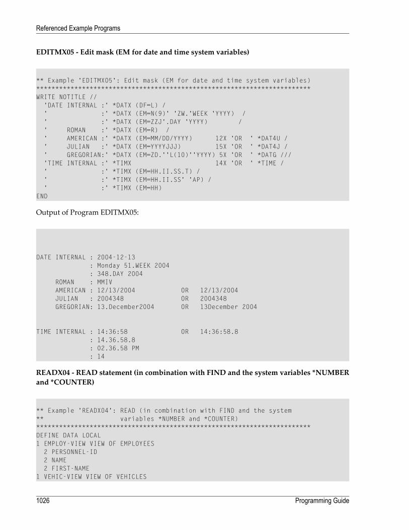
EDITMX05 - Edit mask (EM for date and time system variables)
** Example 'EDITMX05': Edit mask (EM for date and time system variables)************************************************************************WRITE NOTITLE //
'DATE INTERNAL :' *DATX (DF=L) /' :' *DATX (EM=N(9)' 'ZW.'WEEK 'YYYY) /' :' *DATX (EM=ZZJ'.DAY 'YYYY) /' ROMAN :' *DATX (EM=R) /' AMERICAN :' *DATX (EM=MM/DD/YYYY) 12X 'OR ' *DAT4U /' JULIAN :' *DATX (EM=YYYYJJJ) 15X 'OR ' *DAT4J /' GREGORIAN:' *DATX (EM=ZD.''L(10)''YYYY) 5X 'OR ' *DATG ///'TIME INTERNAL :' *TIMX 14X 'OR ' *TIME /' :' *TIMX (EM=HH.II.SS.T) /' :' *TIMX (EM=HH.II.SS' 'AP) /' :' *TIMX (EM=HH)
END
Output of Program EDITMX05:
DATE INTERNAL : 2004-12-13: Monday 51.WEEK 2004: 348.DAY 2004
ROMAN : MMIVAMERICAN : 12/13/2004 OR 12/13/2004JULIAN : 2004348 OR 2004348GREGORIAN: 13.December2004 OR 13December 2004
TIME INTERNAL : 14:36:58 OR 14:36:58.8: 14.36.58.8: 02.36.58 PM: 14
READX04 - READ statement (in combination with FIND and the system variables *NUMBERand *COUNTER)
** Example 'READX04': READ (in combination with FIND and the system** variables *NUMBER and *COUNTER)************************************************************************DEFINE DATA LOCAL1 EMPLOY-VIEW VIEW OF EMPLOYEES
2 PERSONNEL-ID2 NAME2 FIRST-NAME
1 VEHIC-VIEW VIEW OF VEHICLES
Programming Guide1026
Referenced Example Programs
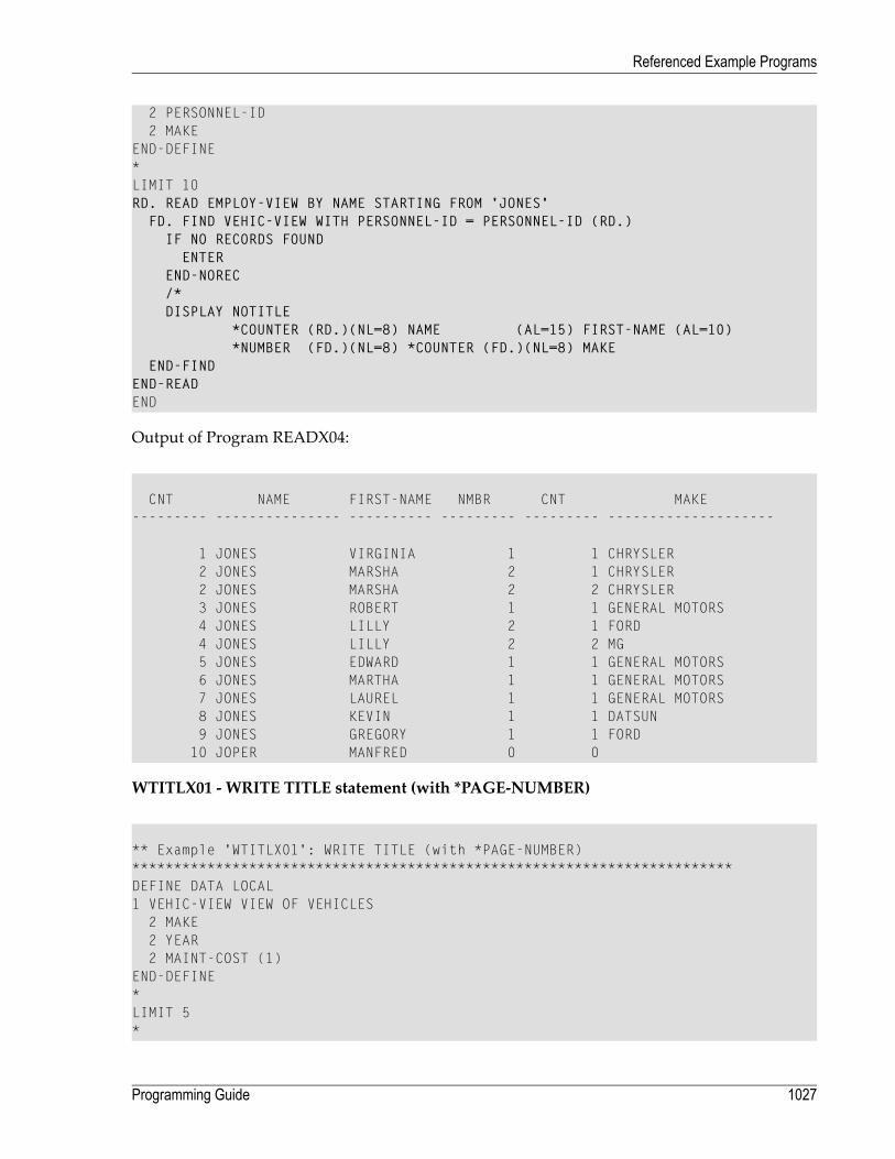
2 PERSONNEL-ID2 MAKE
END-DEFINE*LIMIT 10RD. READ EMPLOY-VIEW BY NAME STARTING FROM 'JONES'
FD. FIND VEHIC-VIEW WITH PERSONNEL-ID = PERSONNEL-ID (RD.)IF NO RECORDS FOUNDENTER
END-NOREC/*DISPLAY NOTITLE
*COUNTER (RD.)(NL=8) NAME (AL=15) FIRST-NAME (AL=10)*NUMBER (FD.)(NL=8) *COUNTER (FD.)(NL=8) MAKE
END-FINDEND-READEND
Output of Program READX04:
CNT NAME FIRST-NAME NMBR CNT MAKE--------- --------------- ---------- --------- --------- --------------------
1 JONES VIRGINIA 1 1 CHRYSLER2 JONES MARSHA 2 1 CHRYSLER2 JONES MARSHA 2 2 CHRYSLER3 JONES ROBERT 1 1 GENERAL MOTORS4 JONES LILLY 2 1 FORD4 JONES LILLY 2 2 MG5 JONES EDWARD 1 1 GENERAL MOTORS6 JONES MARTHA 1 1 GENERAL MOTORS7 JONES LAUREL 1 1 GENERAL MOTORS8 JONES KEVIN 1 1 DATSUN9 JONES GREGORY 1 1 FORD
10 JOPER MANFRED 0 0
WTITLX01 - WRITE TITLE statement (with *PAGE-NUMBER)
** Example 'WTITLX01': WRITE TITLE (with *PAGE-NUMBER)************************************************************************DEFINE DATA LOCAL1 VEHIC-VIEW VIEW OF VEHICLES
2 MAKE2 YEAR2 MAINT-COST (1)
END-DEFINE*LIMIT 5*
1027Programming Guide
Referenced Example Programs

READ VEHIC-VIEWEND-ALLSORT BY YEAR USING MAKE MAINT-COST (1)
DISPLAY NOTITLE YEAR MAKE MAINT-COST (1)AT BREAK OF YEAR
MOVE 1 TO *PAGE-NUMBERNEWPAGE
END-BREAK/*WRITE TITLE LEFT JUSTIFIED
'YEAR:' YEAR 15X 'PAGE' *PAGE-NUMBEREND-SORTEND
Output of ProgramWTITLX01:
YEAR: 1980 PAGE 1YEAR MAKE MAINT-COST----- -------------------- ----------
1980 RENAULT 200001980 RENAULT 200001980 PEUGEOT 20000
System Functions
The following examples are referenced in the section System Variables and System Functions.
ATBREX06 -ATBREAKOFstatement (comparingNMIN,NAVER,NCOUNTwithMIN,AVER,COUNT)
** Example 'ATBREX06': AT BREAK OF (comparing NMIN, NAVER, NCOUNT with** MIN, AVER, COUNT)************************************************************************DEFINE DATA LOCAL1 EMPLOY-VIEW VIEW OF EMPLOYEES
2 CITY2 SALARY (1:2)
END-DEFINE*WRITE TITLE '-- SALARY STATISTICS BY CITY --' /*READ (2) EMPLOY-VIEW WITH CITY = 'NEW YORK'
DISPLAY CITY 'SALARY (1)' SALARY(1) 15X 'SALARY (2)' SALARY(2)AT BREAK OF CITY
WRITE /
Programming Guide1028
Referenced Example Programs

14T 'S A L A R Y (1)' 39T 'S A L A R Y (2)' /13T '- MIN:' MIN(SALARY(1)) 38T '- MIN:' MIN(SALARY(2)) /13T '- AVER:' AVER(SALARY(1)) 38T '- AVER:' AVER(SALARY(2)) /16T COUNT(SALARY(1)) 'RECORDS' 41T COUNT(SALARY(2)) 'RECORDS' //13T '- NMIN:' NMIN(SALARY(1)) 38T '- NMIN:' NMIN(SALARY(2)) /13T '- NAVER:' NAVER(SALARY(1)) 38T '- NAVER:' NAVER(SALARY(2)) /16T NCOUNT(SALARY(1)) 'RECORDS' 41T NCOUNT(SALARY(2)) 'RECORDS'
END-BREAKEND-READEND
Output of Program ATBREX06:
-- SALARY STATISTICS BY CITY --
CITY SALARY (1) SALARY (2)-------------------- ---------- ----------
NEW YORK 17000 16100NEW YORK 38000 34900
S A L A R Y (1) S A L A R Y (2)- MIN: 17000 - MIN: 16100- AVER: 27500 - AVER: 25500
2 RECORDS 2 RECORDS
- NMIN: 17000 - NMIN: 16100- NAVER: 27500 - NAVER: 25500
2 RECORDS 2 RECORDS
ATENPX01 - AT ENDOF PAGE statement (with system function available via GIVE SYSTEMFUNCTIONS in DISPLAY)
** Example 'ATENPX01': AT END OF PAGE (with system function available** via GIVE SYSTEM FUNCTIONS in DISPLAY)************************************************************************DEFINE DATA LOCAL1 EMPLOY-VIEW VIEW OF EMPLOYEES
2 PERSONNEL-ID2 NAME2 JOB-TITLE2 SALARY (1)
END-DEFINE*READ (10) EMPLOY-VIEW BY PERSONNEL-ID = '20017000'
DISPLAY NOTITLE GIVE SYSTEM FUNCTIONSNAME JOB-TITLE 'SALARY' SALARY(1)
/*AT END OF PAGE
1029Programming Guide
Referenced Example Programs

WRITE / 24T 'AVERAGE SALARY: ...' AVER(SALARY(1))END-ENDPAGE
END-READEND
Output of Program ATENPX01:
NAME CURRENT SALARYPOSITION
-------------------- ------------------------- ----------
CREMER ANALYST 34000MARKUSH TRAINEE 22000GEE MANAGER 39500KUNEY DBA 40200NEEDHAM PROGRAMMER 32500JACKSON PROGRAMMER 33000PIETSCH SECRETARY 22000PAUL SECRETARY 23000HERZOG MANAGER 48500DEKKER DBA 48000
AVERAGE SALARY: ... 34270
Programming Guide1030
Referenced Example Programs
Related Documents