Energy 31 (2006) 2073–2081 Reducing CO 2 emissions of internally heat-integrated distillation columns for separation of close boiling mixtures M. Gadalla a, ,Z ˇ . Olujic´ b , A. de Rijke b , P.J. Jansens b a Departament d’Engingeria Quı´mica, Universitat Rovira i Virgili, Paisos Catalans 26, 43007 Tarragona, Spain b Laboratory for Process Equipment, TU Delft, Leeghwaterstraat 44, 2628 CA Delft, The Netherlands Abstract A model developed originally for crude oil distillation units has been applied to a standalone internally heat integrated distillation column (HIDiC) to evaluate emissions levels and to generate design options for direct carbon dioxide emissions reduction. Simulations indicate that for propylene–propane separation, an ideal (no reboiler) HIDiC enables a reduction in emissions of 83% and of 36%, compared to conventional and heat pump alternatives, respectively. Integrating a turbine to drive the compressor, in conjunction with a suitable fuel is the key to the minimization of the emissions associated with the operation of a HIDiC. Importantly, while substantial emission reductions are achieved, the process economics are improved. r 2005 Elsevier Ltd. All rights reserved. 1. Introduction Since distillation columns separating close-boiling mixtures are highly energy intensive, vapour recompression (heat pumping) has been adopted as a technique to increase the energy efficiency of distillation [1–4]. In a direct vapour recompression column (VRC), the vapour leaving the top of the distillation column is compressed and is then condensed in the reboiler of the same column, providing the heat needed for vapour generation at the bottom of the column. Further intensifications of this concept led to the development of internally heat-integrated distillation column (HIDiC). These configurations can have significantly lower energy demand than conventional distillation columns and heat pump assisted alternatives [5–7]. As illustrated in Fig. 1, the HIDiC configuration contains two separate distillation columns, the stripping and rectifying columns. There is a pressure difference between the two columns; the overhead vapour of the stripping column is compressed and then enters the bottom of the rectifying column. The rectifying column operates at a higher pressure, i.e. a higher temperature. The liquid from the bottom of the rectifying column is fed into the top of the stripping column, as is the column feed. The pressure of the recycled liquid stream from the rectifying column is equalised with that of the stripping column through a throttling valve. The vapour leaving the top of the rectifying column is the light product, while the heavy product is the bottom stream of the stripping column. The two columns are configured in a particular way so that the energy of the ARTICLE IN PRESS www.elsevier.com/locate/energy 0360-5442/$ - see front matter r 2005 Elsevier Ltd. All rights reserved. doi:10.1016/j.energy.2005.10.029 Corresponding author. Tel.: +34 977 55 96 61; fax: +34 977 55 96 61. E-mail address: [email protected] (M. Gadalla).

Welcome message from author
This document is posted to help you gain knowledge. Please leave a comment to let me know what you think about it! Share it to your friends and learn new things together.
Transcript
ARTICLE IN PRESS
0360-5442/$ - se
doi:10.1016/j.en
�CorrespondE-mail addr
Energy 31 (2006) 2073–2081
www.elsevier.com/locate/energy
Reducing CO2 emissions of internally heat-integrated distillationcolumns for separation of close boiling mixtures
M. Gadallaa,�, Z. Olujicb, A. de Rijkeb, P.J. Jansensb
aDepartament d’Engingeria Quımica, Universitat Rovira i Virgili, Paisos Catalans 26, 43007 Tarragona, SpainbLaboratory for Process Equipment, TU Delft, Leeghwaterstraat 44, 2628 CA Delft, The Netherlands
Abstract
A model developed originally for crude oil distillation units has been applied to a standalone internally heat integrated
distillation column (HIDiC) to evaluate emissions levels and to generate design options for direct carbon dioxide emissions
reduction. Simulations indicate that for propylene–propane separation, an ideal (no reboiler) HIDiC enables a reduction in
emissions of 83% and of 36%, compared to conventional and heat pump alternatives, respectively. Integrating a turbine to
drive the compressor, in conjunction with a suitable fuel is the key to the minimization of the emissions associated with the
operation of a HIDiC. Importantly, while substantial emission reductions are achieved, the process economics are
improved.
r 2005 Elsevier Ltd. All rights reserved.
1. Introduction
Since distillation columns separating close-boiling mixtures are highly energy intensive, vapourrecompression (heat pumping) has been adopted as a technique to increase the energy efficiency of distillation[1–4]. In a direct vapour recompression column (VRC), the vapour leaving the top of the distillation column iscompressed and is then condensed in the reboiler of the same column, providing the heat needed for vapourgeneration at the bottom of the column. Further intensifications of this concept led to the development ofinternally heat-integrated distillation column (HIDiC). These configurations can have significantly lowerenergy demand than conventional distillation columns and heat pump assisted alternatives [5–7].
As illustrated in Fig. 1, the HIDiC configuration contains two separate distillation columns, the strippingand rectifying columns. There is a pressure difference between the two columns; the overhead vapour of thestripping column is compressed and then enters the bottom of the rectifying column. The rectifying columnoperates at a higher pressure, i.e. a higher temperature. The liquid from the bottom of the rectifying column isfed into the top of the stripping column, as is the column feed. The pressure of the recycled liquid stream fromthe rectifying column is equalised with that of the stripping column through a throttling valve. The vapourleaving the top of the rectifying column is the light product, while the heavy product is the bottom streamof the stripping column. The two columns are configured in a particular way so that the energy of the
e front matter r 2005 Elsevier Ltd. All rights reserved.
ergy.2005.10.029
ing author. Tel.: +34977 55 96 61; fax: +34 977 55 96 61.
ess: [email protected] (M. Gadalla).

ARTICLE IN PRESS
Condenser
Rectifying
Stripping
Reboiler
Compressor
Heat transferFeed
BottomsValve
Fig. 1. Schematic representation of a HIDiC [7].
M. Gadalla et al. / Energy 31 (2006) 2073–20812074
hot-rectifying column is used to heat the stripping column. As a result, continuous condensation of the vapourphase occurs along the rectifying column and continuous evaporation, i.e. vapour generation takes place in thestripping column. The heat is transferred on each integrated column stage through the indirect contact of therectifying hot vapour and the stripping cold liquid streams. The amount of heat transfer between the twocolumns can vary, and correspondingly the reboiler duty will change. When no heat is transferred, the reboilerduty will be the greatest, i.e. equal to that of the conventional column. In other words, a HIDiC may bepartial, when the reboiler energy requirement is reduced, compared to that of a conventional column, or ideal,when the reboiler duty is zero.
The HIDiC concept was first introduced and evaluated by Mah and co-workers [8,9] under the name‘secondary reflux and vaporization’ (SRV). Seader [10], and Glenchur and Govind [11] suggested differentcolumn configurations for HIDiCs implementation. A shell and tube-type packed column was introduced forHIDiC by Aso et al. [12]. Recently, a group of Japanese researchers [13–15] studied HIDiCs, concentrating ontheoretical evaluation and pilot plant testing. Most recently, Gadalla et al. [16] developed a design approachusing pinch analysis principles for improving performances of exiting designs of internal heat-integrateddistillation columns. All these studies indicate significant, practically ultimate energy savings potential withrespect to energy requirements of conventional columns.
Certainly a reduction in energy requirements implies a corresponding indirect reduction of the associatedCO2 emissions. However there is an increasing need for quantification of the accompanying emissions. Mostrecently, a model has been developed by Gadalla et al. [17] for the purpose of quantifying the emissionsassociated with large heat integrated distillation systems, such as those employed in refineries in crude oildistillation units. Internally heat-integrated distillation columns are expected to show a good opportunity foremissions reduction due to their large potential for energy savings. The objective of the present study is touse this method to quantify CO2 emissions from existing designs of HIDiC separating a mixture ofpropylene–propane. Also the potential of these column designs for further emissions reduction compared toconventional alternatives is evaluated, by considering the effect of changing fuels and using gas turbines. Thelatter one appeared to be the key to minimization of emissions associated with operation of a HIDiC.
2. Estimation of CO2 emissions from HIDiCs
Regarding the modelling approach the same working equations as those introduced in the above-mentionedreference are used to estimate CO2 emissions, i.e. fuel equivalents consumed by different configurations of
ARTICLE IN PRESSM. Gadalla et al. / Energy 31 (2006) 2073–2081 2075
HIDiC. In this case the total process heat requirement is equal to the reboiler duty involved, which varies fromzero for an ideal HIDiC to a certain value for a partial HIDiC. Certainly, in an ideal HIDiC case no emissionsare produced due to heating; however, there are still emissions at the central power station for providingcompressor power (electricity) requirement.
The only exception in the calculations procedure is the ideal HIDiC with a turbine used to drive thecompressor. In this case, the required compressor power, which is equal to the power produced by gas turbine,WGT (kW), is given and is used to estimate the mass flow rate of the flue gas, MFG (kg/s), needed by the turbinevia the following empirical equation:MFG ¼ 0:0029W GT . Therefore, in this case no excessive power isavailable, i.e. the CO2 emissions are equivalent to the amount of the fuel consumed by the turbine. However,the equivalent heat of the hot effluent gases of the turbine can be used to provide heat for other processes(energy export or steam saving), including the reboiler duty in case of partial HIDiC, as it will be elaborated inmore detail later on.
3. Case study—a propylene–propane splitter
Propylene–propane splitters are notorious for their immense energy requirements, and as such maincandidates for implementation of energy conserving concepts to single columns. An internally heat-integrateddistillation column was designed for separating an equimolar propylene–propane mixture based on actualplant data for a state of the art heat pump assisted column [18]. The design specifications are shown in Table 1.In this design, the stripping stages are integrated with the top stages of the rectifying column, i.e. the total 57stripping stages are heated by the first top 57 stages of the rectifying section. The ideal HIDiC requires1.54MW of energy to be transferred per stage from the rectifying column to the stripping column. Thecorresponding compressor power is 5.84MW. A conventional column with the same number of stages (basicdata are given in Table 1) consumes 89.2MW; a traditional heat pump assisted column consumes 75.8MW ofheat and its compressor electricity demand is 8.1MW. Note that in heat pump assisted columns, the reboilerdoes not require steam, since the compressed top vapour is used for heating purposes. These results wereobtained by using a rigorous model for distillation column calculations available in Aspen Plus [19]. Thephysical and thermodynamic properties of feed, intermediate and product streams were calculated by the PengRobinson model [19]. Although ideal HIDiC requires no reboiler for heating purposes, a reboiler unit isnecessary for start-up procedure. In this study, the cost of a start-up reboiler is not included, however thisissue will be considered in greater detail in a later stage of design where controllability and operability aspectsof HIDiC and related costs will be stressed on. Namely, for CO2 emissions studies, which compare differentHIDiC configurations, the consideration of start-up reboilers is not essential. In the situations with a partialHIDiC, the same reboiler is used for start-up purposes.
In this study different levels of heat integration are considered, leading to different reboiler duties.Emissions are calculated for a range of reboiler duties, from zero (ideal HIDiC) to the maximum value. When
Table 1
HIDiC problem data and specifications for propylene–propane separation
Feed Propylene–propane
Column specifications
Composition (propylene, mole %) 50
Flow rate (t/h) 111.6
Pressure (bar) 12.2
Temperature (1C) 31.7
Rectifying pressure (bar) 19.2
Stripping pressure (bar) 12.2
Rectifying stages 154
Stripping stages 57
Top product purity (propylene, mole %) 99.6
Bottom product purity (propylene, mole %) 1.1
ARTICLE IN PRESSM. Gadalla et al. / Energy 31 (2006) 2073–20812076
increasing the heat integration level between the two columns, the reboiler duty will reduce. At zero reboilerduty (ideal HIDiC), complete heat integration is exploited; this requires an energy transfer of 1.54MW perstage. This case represents a full energy saving (100%). Note that by increasing heat integration, compressorloads are also increasing. This means that extra money will be spent on both the capital cost and electricityrequirement of the compressor unit. Therefore, an optimisation is required to arrive at the best conditions ofheat integration levels and the corresponding reboiler duty [16]. In what follows, the emissions from HIDiC,with and without turbine, are compared with that associated with conventional and heat pump assistedcolumns, for, respectively, heavy oil and natural gas as fuels.
4. Results and discussion
4.1. CO2 emissions quantification
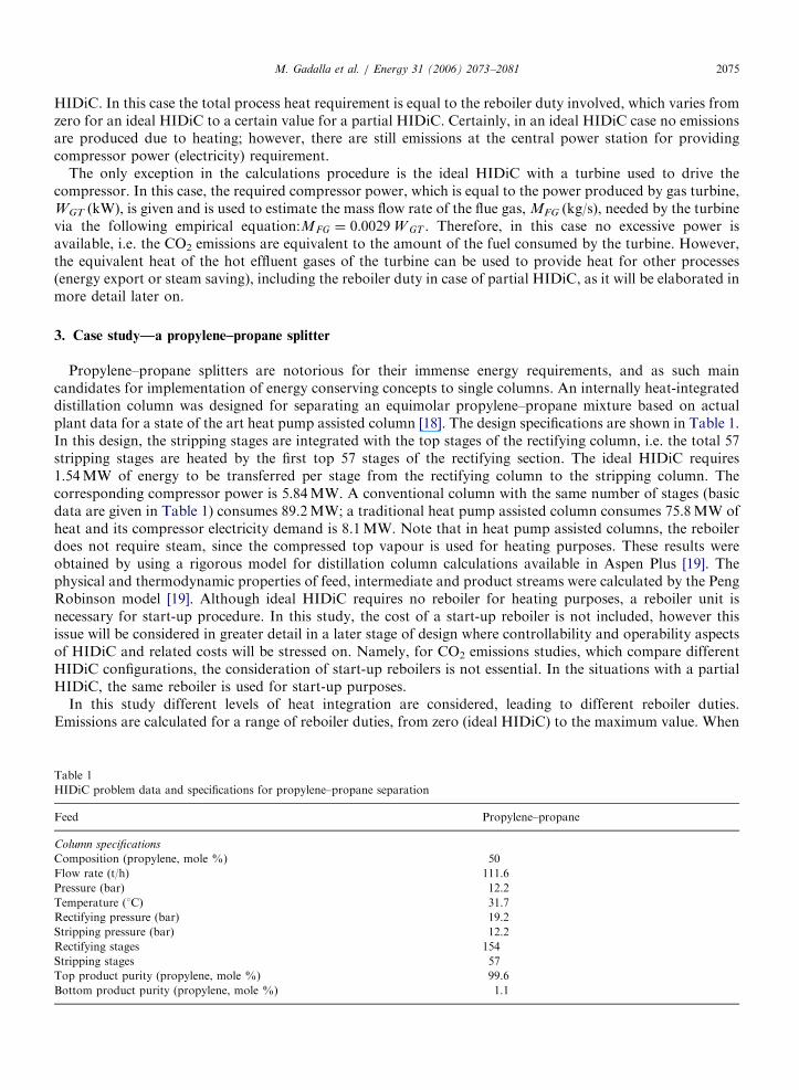
Fig. 2 shows the CO2 emissions calculated for the HIDiCs with different reboiler duties, compared withthose from conventional and heat pump columns. The emissions are produced in the boiler that provides therequired steam and in the power station. A conventional column (fed by fuel oil) produces CO2 emissions ofabout 32 t/h. On the other hand, heat pump design (VRC using fuel oil) produces 8.7 t/h of CO2 globally. Notethat for the vapour recompression column, emissions are produced only at the power station. The localemissions (see Fig. 2) account for emissions from the boilers, while the global emissions include the emissionsof the power station. Thus, the difference between the two emissions represents emissions produced at thepower station. As shown, emissions reduce significantly with reducing the reboiler duty. This indicates thatless steam is needed for heating and consequently the load of the boilers that produce CO2 emissions isreduced. Obviously, the level of emissions is strongly dependent on the nature of the fuel used. Compared toheavy oil, the natural gas can be considered as an environmentally friendly fuel.
The local emissions start (equivalent to maximum reboiler duty) from the same emissions value produced bya conventional alternative and then reduce to zero when an ideal HIDiC is operated, i.e. no reboiler is used.Along the local emissions line, the emissions from the power station are not considered. The global emissionsstart (no heat integration) at a value higher than that of the conventional column and then end at a valuehigher than zero, which is equivalent to the emissions of electricity production. It is clear that at the idealHIDiC conditions, the emissions from HIDiCs are smaller than those from heat pumps (i.e. VRCs). Thisis because the HIDiCs consume less electricity than heat pumps. In order to operate a HIDiC in anenvironmental friendly manner, the reboiler duty needs to be lower than 7.5MW (see Fig. 2); this value isequivalent to the emissions which are produced by heat pump designs. At this reboiler duty, HIDiCs will have
0
5
10
15
20
25
30
35
40
0 20 40 60 80 100Reboiler duty (MW)
CO
2 em
issi
ons
(t/h
)
7.5 MW
Vapour recompression1
Conventional1
HIDiC (local)1HIDiC (global)1
1fuel oil 2 natural gas
HIDiC (global)2
HIDiC (local)2Conventional2
Vapour recompression2
Fig. 2. CO2 emissions from a HIDiC without gas turbine integration; fed by fuel oil or natural gas (column details are given in Table 1).
ARTICLE IN PRESS
-5.0000
0.0000
5.0000
10.0000
15.0000
20.0000
25.0000
30.0000
35.0000
40.0000
45.0000
0 10 20 30 40 50 60 70 80 90 100
Reboiler duty(MW)
CO
2 em
issi
ons
(t/h
)
22 MW
Conventional1
VRC1
HIDiC with turbine1
HIDiC basecase1
HIDiC base case 2
HIDiC with turbine21fuel oil 2natural gas
VRC2
Conventional2
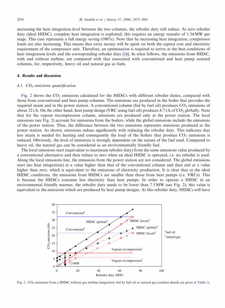
Fig. 3. Global CO2 emissions from a HIDiC with a gas turbine (fed by fuel oil or natural gas).
M. Gadalla et al. / Energy 31 (2006) 2073–2081 2077
the same environmental impact as heat pumps (VRCs). The emissions from an ideal HIDiC are reduced by83% compared to a conventional column, and by 36% compared to a heat pump. These emissions savings areroughly equivalent to the energy savings experienced in these two cases.
When a gas turbine is integrated with a HIDiC, the global emissions are expected to rise compared to theoriginal case (without turbine). This is due to an extra amount of fuel which is burnt by the gas turbine toprovide the required compressor power and heat duty. It is assumed that the excess power produced by theturbine will be exported to the neighbouring site. In addition, the hot flue gases of the gas turbine have asurplus heat that can be exported to other processes and thus extra savings in steams will be gained. This isvalid when HIDiC is ideal, i.e. no reboiler is used.
Fig. 3 illustrates the global CO2 emissions for a HIDiC equipped with a gas turbine, fed either by heavy fueloil or natural gas. As shown, the emissions from the unit with a gas turbine reduce significantly compared tothe base case (without gas turbine). It must be noted that the emissions in this case are divided into three parts,emissions from the steam boiler, the gas turbine and the power station.
As shown in Fig. 3, the emissions for a HIDiC with very small reboiler duties and integrated with a gasturbine are lower than those for a heat pump assisted column (VRC). There is also a sharp decrease in theglobal emissions below a reboiler duty of approximately 40MW. This is because, below this reboiler range, thepower generated in the gas turbine is exactly that required by the compressor. Hence, there is no excess powerto be produced and consequently no additional fuel is burnt by the gas turbine, which reduces emissions.
Furthermore, as indicated in Fig. 3, when the HIDiC is operated with no reboiler and the power required bythe compressor is supplied by the gas turbine the global emissions are negative (�570 kg/h; for fuel oil). This isdue to the fact that no emissions are produced locally by the HIDiC, from the steam boilers or globally due topower consumption. Moreover, the gas turbine has a surplus heat that can be exported. This exported heatprovides an opportunity for other processes to save emissions. Therefore, the reductions in emissions forHIDiCs with turbine are estimated to be above 100%, compared to heat pump assisted columns (VRCs).
When a HIDiC is to be operated with a reboiler, there should be an optimum value for the reboiler duty;this value could be economically driven, related to control issues or related to environmental consequences.For the environmental perspective, the results of Fig. 3 may suggest that the reboiler duty should be below22MW. At these conditions, the emissions from HIDiCs will be less than or equal to those of the heat pumpedalternative. Therefore, the environmental impact will be no greater than that for an efficient heat pumpassisted column design (VRC).
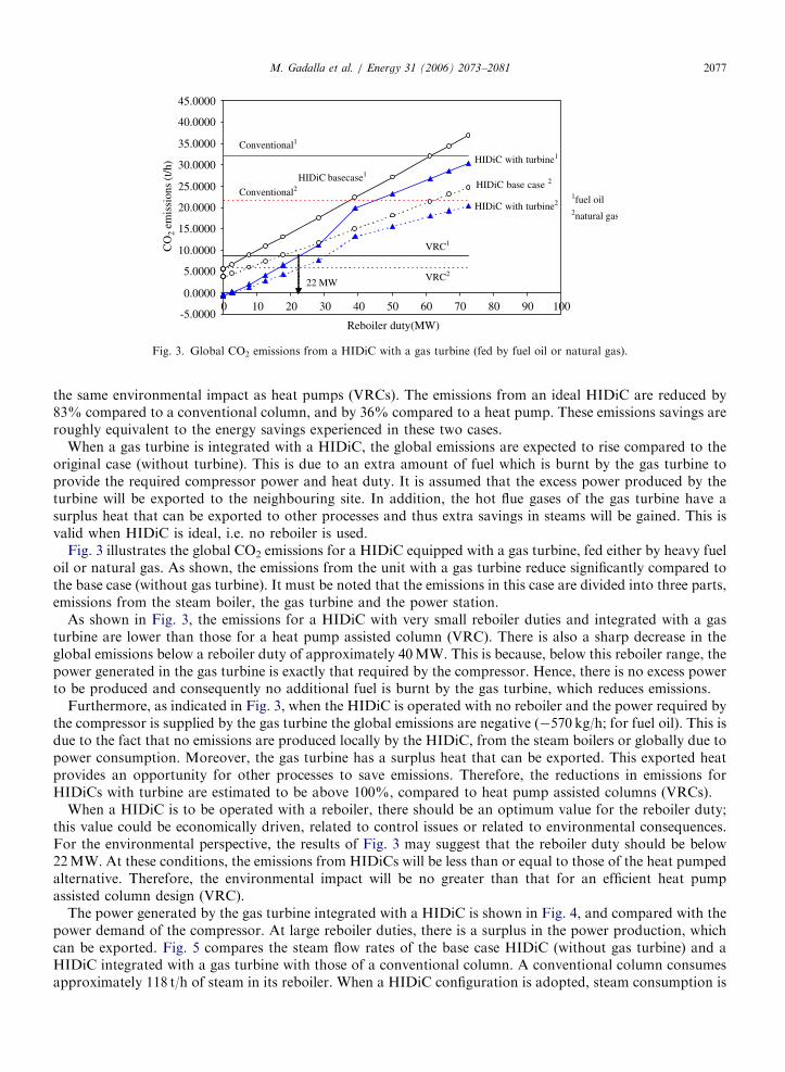
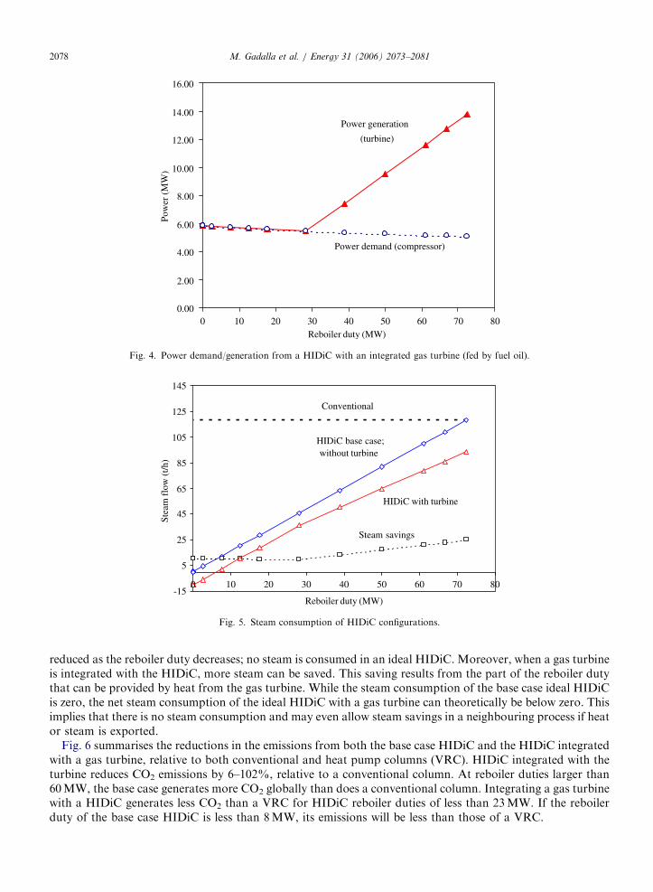
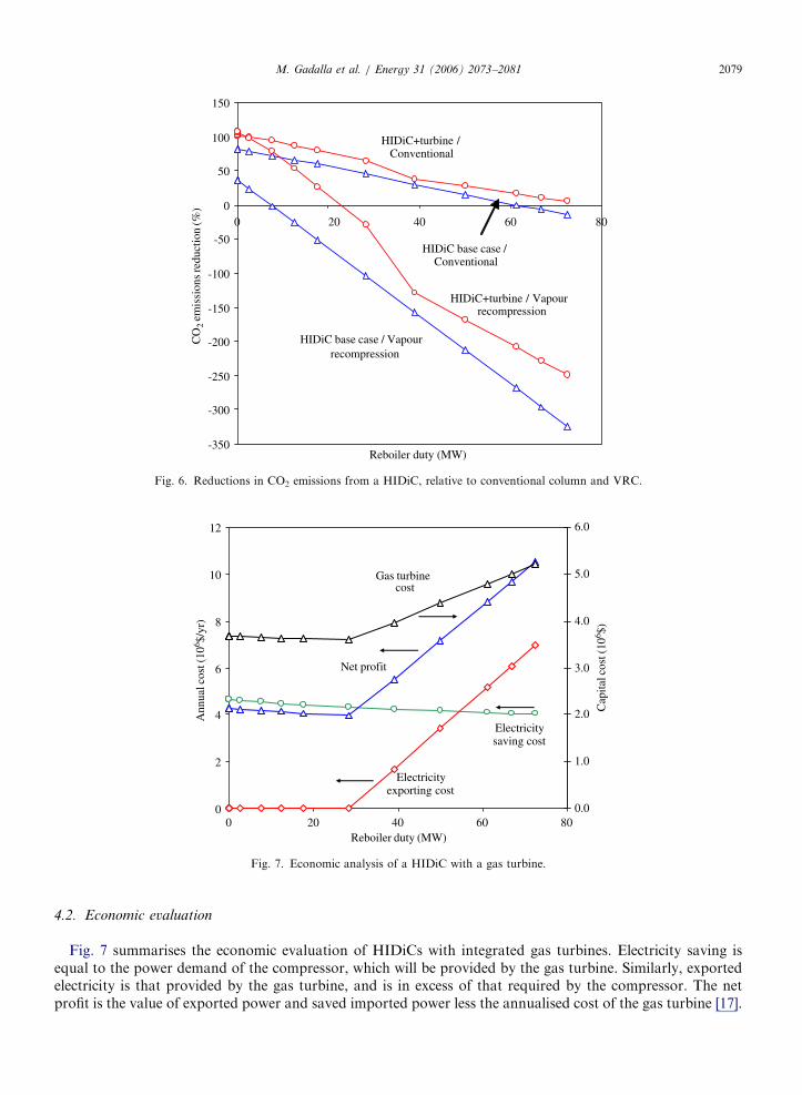
The power generated by the gas turbine integrated with a HIDiC is shown in Fig. 4, and compared with thepower demand of the compressor. At large reboiler duties, there is a surplus in the power production, whichcan be exported. Fig. 5 compares the steam flow rates of the base case HIDiC (without gas turbine) and aHIDiC integrated with a gas turbine with those of a conventional column. A conventional column consumesapproximately 118 t/h of steam in its reboiler. When a HIDiC configuration is adopted, steam consumption is
ARTICLE IN PRESS
0.00
2.00
4.00
6.00
8.00
10.00
12.00
14.00
16.00
0 10 20 30 40 50 60 70 80Reboiler duty (MW)
Pow
er (
MW
)
Power demand (compressor)
Power generation
(turbine)
Fig. 4. Power demand/generation from a HIDiC with an integrated gas turbine (fed by fuel oil).
-15
5
25
45
65
85
105
125
145
0 10 20 30 40 50 60 70 80
Reboiler duty (MW)
Stea
m f
low
(t/h
)
Conventional
Steam savings
HIDiC with turbine
HIDiC base case;without turbine
Fig. 5. Steam consumption of HIDiC configurations.
M. Gadalla et al. / Energy 31 (2006) 2073–20812078
reduced as the reboiler duty decreases; no steam is consumed in an ideal HIDiC. Moreover, when a gas turbineis integrated with the HIDiC, more steam can be saved. This saving results from the part of the reboiler dutythat can be provided by heat from the gas turbine. While the steam consumption of the base case ideal HIDiCis zero, the net steam consumption of the ideal HIDiC with a gas turbine can theoretically be below zero. Thisimplies that there is no steam consumption and may even allow steam savings in a neighbouring process if heator steam is exported.
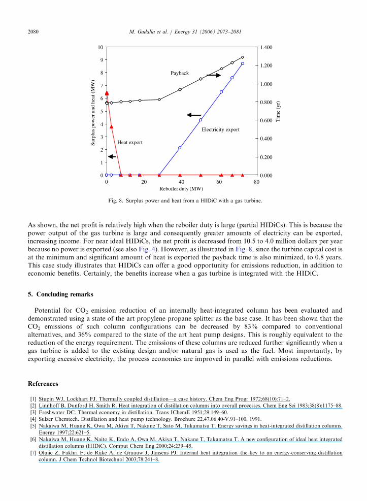
Fig. 6 summarises the reductions in the emissions from both the base case HIDiC and the HIDiC integratedwith a gas turbine, relative to both conventional and heat pump columns (VRC). HIDiC integrated with theturbine reduces CO2 emissions by 6–102%, relative to a conventional column. At reboiler duties larger than60MW, the base case generates more CO2 globally than does a conventional column. Integrating a gas turbinewith a HIDiC generates less CO2 than a VRC for HIDiC reboiler duties of less than 23MW. If the reboilerduty of the base case HIDiC is less than 8MW, its emissions will be less than those of a VRC.
ARTICLE IN PRESS
-350
-300
-250
-200
-150
-100
-50
0
50
100
150
0 20 40 60 80
Reboiler duty (MW)
CO
2 em
issi
ons
redu
ctio
n (%
)
HIDiC base case / Vapourrecompression
HIDiC+turbine / Vapourrecompression
HIDiC base case /Conventional
HIDiC+turbine /Conventional
Fig. 6. Reductions in CO2 emissions from a HIDiC, relative to conventional column and VRC.
0
2
4
6
8
10
12
0 20 40 60 80Reboiler duty (MW)
Ann
ual c
ost (
106 $/
yr)
0.0
1.0
2.0
3.0
4.0
5.0
6.0
Cap
ital c
ost (
106 $)
Gas turbinecost
Net profit
Electricitysaving cost
Electricityexporting cost
Fig. 7. Economic analysis of a HIDiC with a gas turbine.
M. Gadalla et al. / Energy 31 (2006) 2073–2081 2079
4.2. Economic evaluation
Fig. 7 summarises the economic evaluation of HIDiCs with integrated gas turbines. Electricity saving isequal to the power demand of the compressor, which will be provided by the gas turbine. Similarly, exportedelectricity is that provided by the gas turbine, and is in excess of that required by the compressor. The netprofit is the value of exported power and saved imported power less the annualised cost of the gas turbine [17].
ARTICLE IN PRESS
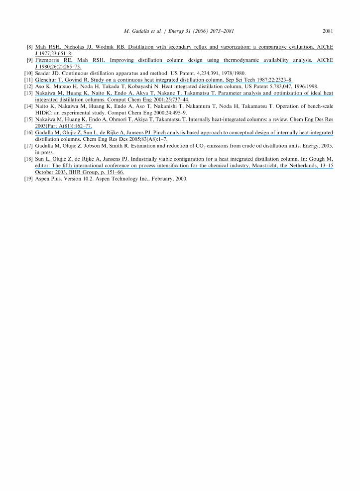
0
1
2
3
4
5
6
7
8
9
10
0 20 40 60 80Reboiler duty (MW)
Surp
lus
pow
er a
nd h
eat (
MW
)
0.000
0.200
0.400
0.600
0.800
1.000
1.200
1.400
Tim
e (y
r)
Payback
Heat export
Electricity export
Fig. 8. Surplus power and heat from a HIDiC with a gas turbine.
M. Gadalla et al. / Energy 31 (2006) 2073–20812080
As shown, the net profit is relatively high when the reboiler duty is large (partial HIDiCs). This is because thepower output of the gas turbine is large and consequently greater amounts of electricity can be exported,increasing income. For near ideal HIDiCs, the net profit is decreased from 10.5 to 4.0 million dollars per yearbecause no power is exported (see also Fig. 4). However, as illustrated in Fig. 8, since the turbine capital cost isat the minimum and significant amount of heat is exported the payback time is also minimized, to 0.8 years.This case study illustrates that HIDiCs can offer a good opportunity for emissions reduction, in addition toeconomic benefits. Certainly, the benefits increase when a gas turbine is integrated with the HIDiC.
5. Concluding remarks
Potential for CO2 emission reduction of an internally heat-integrated column has been evaluated anddemonstrated using a state of the art propylene-propane splitter as the base case. It has been shown that theCO2 emissions of such column configurations can be decreased by 83% compared to conventionalalternatives, and 36% compared to the state of the art heat pump designs. This is roughly equivalent to thereduction of the energy requirement. The emissions of these columns are reduced further significantly when agas turbine is added to the existing design and/or natural gas is used as the fuel. Most importantly, byexporting excessive electricity, the process economics are improved in parallel with emissions reductions.
References
[1] Stupin WJ, Lockhart FJ. Thermally coupled distillation—a case history. Chem Eng Progr 1972;68(10):71–2.
[2] Linnhoff B, Dunford H, Smith R. Heat integration of distillation columns into overall processes. Chem Eng Sci 1983;38(8):1175–88.
[3] Freshwater DC. Thermal economy in distillation. Trans IChemE 1951;29:149–60.
[4] Sulzer Chemtech. Distillation and heat pump technology. Brochure 22.47.06.40-V.91–100, 1991.
[5] Nakaiwa M, Huang K, Owa M, Akiya T, Nakane T, Sato M, Takamatsu T. Energy savings in heat-integrated distillation columns.
Energy 1997;22:621–5.
[6] Nakaiwa M, Huang K, Naito K, Endo A, Owa M, Akiya T, Nakane T, Takamatsu T. A new configuration of ideal heat integrated
distillation columns (HIDiC). Comput Chem Eng 2000;24:239–45.
[7] Olujic Z, Fakhri F, de Rijke A, de Graauw J, Jansens PJ. Internal heat integration–the key to an energy-conserving distillation
column. J Chem Technol Biotechnol 2003;78:241–8.
ARTICLE IN PRESSM. Gadalla et al. / Energy 31 (2006) 2073–2081 2081
[8] Mah RSH, Nicholas JJ, Wodnik RB. Distillation with secondary reflux and vaporization: a comparative evaluation. AIChE
J 1977;23:651–8.
[9] Fitzmorris RE, Mah RSH. Improving distillation column design using thermodynamic availability analysis. AIChE
J 1980;26(2):265–73.
[10] Seader JD. Continuous distillation apparatus and method. US Patent, 4,234,391, 1978/1980.
[11] Glenchur T, Govind R. Study on a continuous heat integrated distillation column. Sep Sci Tech 1987;22:2323–8.
[12] Aso K, Matsuo H, Noda H, Takada T, Kobayashi N. Heat integrated distillation column, US Patent 5,783,047, 1996/1998.
[13] Nakaiwa M, Huang K, Naito K, Endo A, Akya T, Nakane T, Takamatsu T. Parameter analysis and optimization of ideal heat
integrated distillation columns. Comput Chem Eng 2001;25:737–44.
[14] Naito K, Nakaiwa M, Huang K, Endo A, Aso T, Nakanishi T, Nakamura T, Noda H, Takamatsu T. Operation of bench-scale
HIDiC: an experimental study. Comput Chem Eng 2000;24:495–9.
[15] Nakaiwa M, Huang K, Endo A, Ohmori T, Akiya T, Takamatsu T. Internally heat-integrated columns: a review. Chem Eng Des Res
2003(Part A(81)):162–77.
[16] Gadalla M, Olujic Z, Sun L, de Rijke A, Jansens PJ. Pinch analysis-based approach to conceptual design of internally heat-integrated
distillation columns. Chem Eng Res Des 2005;83(A8):1–7.
[17] Gadalla M, Olujic Z, Jobson M, Smith R. Estimation and reduction of CO2 emissions from crude oil distillation units. Energy, 2005,
in press.
[18] Sun L, Olujic Z, de Rijke A, Jansens PJ. Industrially viable configuration for a heat integrated distillation column. In: Gough M,
editor. The fifth international conference on process intensification for the chemical industry, Maastricht, the Netherlands, 13–15
October 2003, BHR Group, p. 151–66.
[19] Aspen Plus. Version 10.2. Aspen Technology Inc., February, 2000.
Related Documents


