Recommendations for Updating the Technical Requirements for Inverters in Distributed Energy Resources Smart Inverter Working Group Recommendations January 2014 FILED 2-07-14 10:09 AM

Welcome message from author
This document is posted to help you gain knowledge. Please leave a comment to let me know what you think about it! Share it to your friends and learn new things together.
Transcript
Recommendations for Updating the Technical Requirements for Inverters in
Distributed Energy Resources
Smart Inverter Working Group Recommendations
January 2014
FILED2-07-1410:09 AM

SIWG Rule 21 Recommendations for the CPUC Page i
Contents1. Introduction .............................................................................................................................. 7
1.1 California’s Electric Tariff Rule 21 ....................................................................................... 7
1.2 California’s Distributed Generation Policy Goals ................................................................ 8
1.3 Technical Challenges Associated with Widespread Adoption of Distributed Generation .......................................................................................................................... 9
1.4 The Potential for Optimizing Distributed Generation within the Distribution System ...... 9
1.5 The International and California Backdrop ....................................................................... 11 1.5.1 European and International Efforts ................................................................ 11 1.5.2 IEEE 1547 Update Status and Relationship to Rule 21 .................................... 12 1.5.3 California’s Smart Inverter Working Group (SIWG) ........................................ 13
1.6 Implementation Road Map ............................................................................................... 14
1.7 Proposed Phase 1: Autonomous Inverter Functionalities Recommended as Technical Operating Standards within Electric Tariff Rule 21 ........................................................... 17 1.7.1 Enabling Proposed Phase 1 Autonomous Inverter Functionalities ................. 17 1.7.2 Defining the Potential Phase 2 Communications Standards for Smart
Inverters ......................................................................................................... 19 1.7.3 Defining the Potential Phase 3 Additional Advanced Smart Inverter
Functionalities ................................................................................................ 19
2. Proposed Phase 1: Detailed Autonomous Inverter Functionalities Recommended as Technical Operating Standards within Electric Tariff Rule 21 ................................................ 21
2.1 Anti‐Islanding Protection .................................................................................................. 21 2.1.1 Purpose of Anti‐Islanding Protection ............................................................. 21 2.1.2 Current Rule 21 Requirements for Anti‐Islanding........................................... 21 2.1.3 Issues with Current Rule 21 Anti‐Islanding Requirements .............................. 21 2.1.4 Proposed Anti‐Islanding Requirements for Rule 21 ........................................ 22 2.1.5 Proposed Rule 21 Text Modifications for Anti‐Islanding ................................ 22 2.1.6 Benefits of the Proposed New Anti‐Islanding Requirements ......................... 22
2.2 Low/High Voltage Ride‐Through (L/HVRT) ....................................................................... 22 2.2.1 Purpose of L/HVRT ......................................................................................... 22 2.2.2 Current Rule 21 Requirements for L/HVRT ..................................................... 23 2.2.3 Issues with Current Rule 21 L/HVRT ............................................................... 23 2.2.4 L/HVRT Function Concepts ............................................................................. 23 2.2.5 Proposed Rule 21 Default Voltage Ride‐Through Requirements .................... 24 2.2.6 Proposed Rule 21 Text Modification for L/HVRT ............................................ 26 2.2.7 Benefits of the Proposed L/HVRT Requirements ............................................ 26
2.3 Low/High Frequency Ride‐Through (L/HFRT) ................................................................... 26 2.3.1 Purpose of L/HFRT .......................................................................................... 26 2.3.2 Current Rule 21 Requirements for L/HFRT ..................................................... 27 2.3.3 Issues with Current Rule 21 L/HFRT ............................................................... 27

SIWG Rule 21 Recommendations for the CPUC Page ii
2.3.4 L/HFRT Function Concepts ............................................................................. 27 2.3.5 Proposed Rule 21 Default Frequency Ride‐Through Requirements ............... 29 2.3.6 Proposed Rule 21 Text Modification for L/HFRT ............................................ 30 2.3.7 Benefits of the Proposed L/HFRT Requirements ............................................ 30
2.4 Dynamic Volt/Var Operations ........................................................................................... 31 2.4.1 Purpose of Dynamic Volt/Var Operations ...................................................... 31 2.4.2 Current Rule 21 Requirements for Dynamic Volt/Var Operations .................. 31 2.4.3 Issues with Current Rule 21 Dynamic Volt/Var Operations ............................ 31 2.4.4 Dynamic Volt/Var Operations Concepts ......................................................... 31 2.4.5 Proposed Rule 21 Default Dynamic Volt/Var Operation Requirements ......... 32 2.4.6 Proposed Rule 21 Text Modification for Dynamic Volt/Var Operations ......... 34 2.4.7 Benefits of the Proposed Dynamic Volt/Var Operations Requirements ......... 35
2.5 Ramp Rates ....................................................................................................................... 35 2.5.1 Purpose of Ramp Rates .................................................................................. 35 2.5.2 Current Rule 21 Requirements for Ramp Rates .............................................. 35 2.5.3 Issues with Current Rule 21 on Ramp Rates ................................................... 35 2.5.4 Proposed Ramp Rate Requirements ............................................................... 35 2.5.5 Proposed Rule 21 Text Modification for Ramp Rates ..................................... 36 2.5.6 Benefits of the Proposed Ramp Rate Requirements ...................................... 36
2.6 Fixed Power Factor ........................................................................................................... 37 2.6.1 Purpose of Fixed Power Factor (PF)................................................................ 37 2.6.2 Current Rule 21 Requirements for Fixed Power Factor .................................. 37 2.6.3 Issues with the Current Rule 21 Requirement for Fixed Power Factor ........... 37 2.6.4 Fixed Power Factor Concepts ......................................................................... 37 2.6.5 Proposed Fixed Power Factor Requirements .................................................. 37 2.6.6 Proposed Rule 21 Text Modification .............................................................. 37 2.6.7 Benefits of the Proposed Fixed Power Factor Capability ................................ 38
2.7 Reconnect by “Soft‐Start” Methods ................................................................................. 38 2.7.1 Purpose of Reconnection by “Soft‐Start” Methods ........................................ 38 2.7.2 Current Rule 21 Requirements on Reconnection ........................................... 38 2.7.3 Issues with Current Rule 21 on Reconnection ................................................ 38 2.7.4 “Soft‐Start” Reconnection Concepts .............................................................. 38 2.7.5 Proposed Rule 21 Reconnection Requirements ............................................. 39 2.7.6 Proposed Rule 21 Text Modifications for “Soft‐Start” Reconnection ............. 39 2.7.7 Benefits of the Proposed “Soft‐Start” Reconnection ...................................... 39
2.8 Phase 1 I‐DER System Parameters and Monitored Points................................................ 39 2.8.1 Phase 1 I‐DER Parameters for Manufacturers ................................................ 39 2.8.2 Nameplate Information .................................................................................. 43 2.8.3 I‐DER System Monitored Points for Testing ................................................... 44 2.8.4 Default Activation States for Phase 1 Functions ............................................. 45 2.8.5 Default Prioritization of Phase 1 Functions .................................................... 45
3. Defining the Potential Phase 2 Communications Technologies for I‐DER Functions ............. 47
SIWG Rule 21 Recommendations for the CPUC Page iii
3.1 Purpose of Communications Technologies for I‐DER functions ....................................... 47
3.2 Current Rule 21 Requirements for Communications ....................................................... 47
3.3 Problems Created by the Absence of a Statewide Communication Standard for DER Systems ............................................................................................................................. 48
3.4 Communications Concepts and Issues ............................................................................. 48 3.4.1 Hierarchical Models of DER System Configurations ....................................... 48 3.4.2 Communications Alternatives ........................................................................ 52
3.5 Proposed Communications Requirements for Rule 21 .................................................... 53
3.6 Benefits of Communications with I‐DER Systems ............................................................. 54
4. Defining the Potential Phase 3 Additional Advanced Inverter Functionalities ...................... 55
4.1 Purpose of the Additional Advanced Inverter Functionalities ......................................... 55
4.2 Early Definition of Advanced Inverter Functionalities for Rule 21 ................................... 55
4.3 Benefits of the Additional Advanced Inverter Functionalities ......................................... 57
5. Proposed Test Plan for Smart I‐DER Systems ......................................................................... 58 5.1.1 Scope and Purpose ......................................................................................... 58 5.1.2 Types of Tests ................................................................................................. 58 5.1.3 Sources of Testing Requirements ................................................................... 59
5.2 Implementation Procedures ............................................................................................. 59 5.2.1 UL Certification for Pilot and for Commercial I‐DER Systems ......................... 59 5.2.2 Permissive Implementation Schedules ........................................................... 60 5.2.3 Staggered Test groups .................................................................................... 60
5.3 Schedules for Permissive Implementations of Staggered Testing of Smart I‐DER Functions ........................................................................................................................... 61 5.3.1 Gantt Chart of Testing and Implementation Schedules .................................. 63 5.3.2 CPUC‐Related Tasks: Review, Comment, and Update CPUC On‐Record
Documents ..................................................................................................... 64 5.3.3 Upcoming Smart Inverter Working Group (SIWG) Tasks ................................ 65 5.3.4 Test group A – Phase 1 Autonomous Functions for Larger I‐DER Systems ..... 66 5.3.5 Test group B – Phase 1 Autonomous Functions for Smaller I‐DER Systems.... 66 5.3.6 Test group C – Phase 2 Communications Capabilities for I‐DER Systems ....... 67 5.3.7 Test group D – Phase 3 Additional I‐DER Functions ........................................ 68
6. Proposed Milestones .............................................................................................................. 70
7. Conclusion ............................................................................................................................... 71
A. Appendix A: Chart of Mandatory, Recommended, Optional I‐DER Functions ....................... 72
A.1 Phase 1: Key Autonomous I‐DER Functions ...................................................................... 72
A.2 Phase 2: Communications Technologies for I‐DER Functions .......................................... 75
A.3 Phase 3: I‐DER Functions Requiring Communications ...................................................... 76
A.4 Phase 3: Additional Autonomous I‐DER Functions ........................................................... 79
A.5 Optional I‐DER Functions .................................................................................................. 81
SIWG Rule 21 Recommendations for the CPUC Page iv
B. Appendix B: Definitions of Terms and Acronyms ................................................................... 84
C. Appendix C: Smart Inverter Working Group Participants ....................................................... 87

SIWG Rule 21 Recommendations for the CPUC Page v
Figures
Figure 1: Must disconnect and must remain connected zones ............................................. 24
Figure 2: Graph of default voltage ride‐through settings (see table for actual settings) ...... 26
Figure 3: NERC’s Graph of Off‐Nominal Frequency Curves for Different Interconnections ... 28
Figure 4: Graph of default frequency parameters (see tables for detailed settings and ranges) .................................................................................................................................. 30
Figure 5: Example settings of volt/var mode using available vars and a deadband around the nominal voltage (P2‐P3) ........................................................................................................ 32
Figure 6: Example of volt/var curve with hysteresis, with arrows indicating direction of voltage changes .................................................................................................................... 32
Figure 7: P‐Q capability curve (P: real power; Q: reactive power; S: apparent power) ......... 33
Figure 8: 5 Levels of the Hierarchical DER System Architecture Showing Communications Protocols ............................................................................................................................... 50
Figure 9: Communication layers, possible communications protocols choices, and an example of a communications gateway for translating protocols ........................................ 53
Figure 10: Staggered Test groups .......................................................................................... 61
SIWG Rule 21 Recommendations for the CPUC Page vi
Tables
Table 1: Default Rule 21 voltage ride‐through voltage‐time values ...................................... 25
Table 2: NERC’s Western Interconnection Transmission Off‐Nominal Frequency Durations 28
Table 3: WECC Off Nominal Frequency Load Shedding Limits ............................................... 29
Table 4: Default interconnection system response to abnormal frequencies ....................... 30
Table 5: Default volt/var settings .......................................................................................... 34
Table 6: Phase 1 I‐DER Parameters ....................................................................................... 40
Table 7: Nameplate and Static Settings ................................................................................ 43
Table 8: I‐DER System Monitored Points .............................................................................. 44
Table 9: Initial Tasks: Review, Comment, and Update Documents ....................................... 64
Table 10: Smart Inverter Working Group Tasks .................................................................... 65
Table 11: Test group A – Phase 1 Autonomous Functions for Larger I‐DER Systems ............ 66
Table 12: Test group B – Phase 1 Autonomous Functions for Smaller I‐DER Systems ........... 67
Table 13: Test group C – Phase 2 Communications Capabilities for I‐DER Systems .............. 68
Table 14: Test group D – Phase 3 Autonomous I‐DER Functions ........................................... 69
Table 15: Milestones ............................................................................................................. 70
Table 16: Phase 1 Basic Autonomous I‐DER functions .......................................................... 73
Table 17: Standards‐based communications technologies requirements ............................. 75
Table 18: I‐DER functions requiring communications ........................................................... 77
Table 19: Phase 3 Additional Autonomous I‐DER functions .................................................. 79
Table 20: Optional I‐DER Functions ....................................................................................... 81
Table 21: List of SIWG Participants ....................................................................................... 87
SIWG Rule 21 Recommendations for the CPUC Page 7
1. Introduction
Governor Jerry Brown’s goal of adding 12,000 MW of distributed generation to California’s electrical grid by 2020 creates a technical challenge. At such a scale, Distributed Energy Resource (DER)1 systems have the potential to provide significant environmental and financial benefits to California. At the same time, achieving this goal will require a fundamental paradigm shift in the technical operation of the distribution system.
The core technical challenge is this: Today, DER systems are interconnected to distribution grids originally designed for one‐way flows of power from substations through the grid to customer loads. Distributed generation introduces two‐way power flows, at sites dispersed throughout the system; where the source is renewable energy, the generation itself is intermittent. The technical operating standards set out in California’s interconnection rules accommodate the power flows from DER systems, but do not optimize the distributed generation to support distribution system operations.
The purpose of this document is to set out the technical steps for the paradigm shift that is needed as California approaches greater numbers of installed DER systems, higher penetrations on certain circuits, and the implementation of a smart distribution system that optimizes interconnected resources. The three major technical steps discussed and proposed here are: first, adoption of certain autonomous functionalities to be performed by certain DER systems; second, a commitment to define and propose communication standards for certain DER systems; and third, a commitment to define and propose advanced functionalities utilizing the communications capabilities. The ultimate goal is more efficient management of the distribution system while maintaining standards of reliable and safe service.
This proposal is the product of the Smart Inverter Working Group (SIWG), which was formed in early 2013 as a joint effort between the CPUC and California Energy Commission (CEC) in order to develop recommendations to the CPUC for the technical steps to be taken in order to optimize inverter‐based DER to support distribution system operations.
1.1 California’s Electric Tariff Rule 21
California’s Electric Tariff Rule 21 (Rule 21) is a CPUC‐approved tariff that describes the interconnection, operating and metering requirements for generation facilities to be connected to an investor‐owned utility’s distribution system, over which the California Public Utilities Commission (CPUC) has jurisdiction.2 The CPUC requires that the technical operating standards and interconnection procedures in Rule 21 for each of California’s IOUs are identical.
1 Distributed Energy Resources (DER) systems are defined in this document as all generation and storage devices connected directly or indirectly (behind the customer’s meter) to the utility’s distribution system.
2 California’s investor‐owned utilities are Pacific Gas and Electric Company (PG&E), San Diego Gas & Electric Company (SDG&E), and Southern California Edison (SCE), collectively referred to here as “IOUs.”

SIWG Rule 21 Recommendations for the CPUC Page 8
The CPUC originally adopted Rule 21 in the 1980s to provide for the interconnection of non‐utility owned generation following enactment of the Public Utilities Regulatory Policies Act (PURPA), in 1978. During the 1980s and 1990s, Rule 21 was primarily used to interconnect “qualifying facilities” pursuant to PURPA. With the rise of customer‐side generation in the 1990s, the CPUC modified Rule 21 significantly in 2000 to provide for simplified interconnection for small, net energy metered systems.
The CPUC has modified Rule 21 in response to market and regulatory changes. Most recently, the CPUC opened a rulemaking to evaluate whether the tariff is achieving the CPUC’s goals for a transparent, timely, cost‐effective and technology‐neutral interconnection process. The scope for phase two of this rulemaking includes an examination of the technical operating standards in Rule 21, and the potential introduction of smart inverter functionalities.
1.2 California’s Distributed Generation Policy Goals
California Governor Jerry Brown has called for 12,000 MW of “localized electricity generation”, or DER, to help the State procure 33 percent of its energy from renewable resources by 2020. The programs that the CPUC has implemented or is currently implementing to achieve Governor Brown’s distributed generation goal including: the California Solar Initiative (CSI) program, the Self‐Generation Incentive Program (SGIP), the Renewable Market Adjusting Tariff, or ReMAT, and the AB 1613 highly efficient combined heat and power (CHP) feed‐in tariff. In addition, the net energy metering (NEM) program, an important program supporting widespread installation of DER systems, continues to incorporate new models, such as load aggregation for larger contiguous properties, Virtual Net Energy Metering for multi‐family housing, and renewable generation paired with storage.3
Within this diverse DER marketplace, solar photovoltaics, which use an inverter to convert their power from direct current to alternating current, predominate, although other inverter‐based DER systems can also provide significant distributed generation and storage energy. This document proposes that these inverter‐based “I‐DER” systems must include new functions and capabilities that will enable them to support distribution grid operations to better cope with this paradigm shift. Instead of protecting distribution grids against possible undesirable impacts of I‐DER systems, as interconnection standards presently do, the recommendations here establish programmable functions that I‐DER systems will perform to support power system operations.
3 An overview of the status of Distributed Generation in California can be found in “Biennial Report on Impacts of Distributed Generation”, prepared in compliance with Assembly Bill 578 (2008, Blakeslee). Available for download at http://www.cpuc.ca.gov/NR/rdonlyres/29DCF6CC‐45BC‐4875‐9C7D‐F8FD93B94213/0/CPUCDGImpactReportFinal2013_05_23.pdf

SIWG Rule 21 Recommendations for the CPUC Page 9
1.3 Technical Challenges Associated with Widespread Adoption of Distributed Generation
The core technical challenge is this: Today, DER systems are interconnected to distribution grids originally designed for one‐way flows of power from substations through the grid to customer loads. Distributed generation introduces two‐way power flows, at sites dispersed throughout the system, and where the source is renewable energy, the generation itself is intermittent. The technical operating standards set out in California’s interconnection rules accommodate the current small amounts of the power flows from DER systems, but will not adequately cope with the expected large amounts of the distributed generation to support the paradigm shift in distribution system.
This increasing number of DER systems can impact the stability, reliability, and efficiency of power grid operations. First, DER systems are usually located for the convenience of the DER owner, not the utility, and therefore may be in less‐than‐optimal locations from the perspective of grid operators. Second, DER systems are of widely varying sizes and purposes (e.g., as secondary to offsetting customers’ loads and/or their power production). Third, without coordination with the distribution equipment on the grid, DER systems could actually cause voltage oscillations, create reverse power flows on circuits not designed for two‐way flows, and cause other power system impacts that could actually increase the frequency and durations of outages.
The policy driver for most of California’s distributed generation programs has been to stimulate market development and support emerging technology. To date, the California interconnection standards have not yet focused on integrating or coordinating DER systems; instead, DER systems are tolerated but are required to trip‐off instantaneously in the event of any distribution system disturbance. This approach has recently led to grid stability problems in other countries with high penetrations of DER systems. Specifically, Germany and Italy have observed that allowing DER systems to trip‐off prematurely during voltage or frequency anomalies can actually exacerbate those problems, possibly causing unnecessary outages.4
1.4 The Potential for Optimizing Distributed Generation within the Distribution System
In California, ambitious policy goals for DER systems are causing a paradigm shift in power system management, reflecting the new capabilities provided by the following technologies:
DER systems can become very powerful tools for managing reliability and power quality. Local generators have been used for decades to improve the reliability of industrial facilities that have critical loads, and are often deployed in addition to local
4 European Network of Transmission System Operators for Electricity (ENTSO‐E) SPD Report “Dispersed Generation Impact On CE Region Security, Dynamic Study, Final Report”, 22‐03‐2013. See also California Energy Commission, “European Renewable Distributed Generation Infrastructure Study‐Lessons Learned from Electricity Markets in Germany and Spain ‐ Consultant Report”, December 2011, CEC‐400‐2011‐011. Available at: “http://www.energy.ca.gov/publications/displayOneReport.php?pubNum=CEC‐400‐2011‐011
SIWG Rule 21 Recommendations for the CPUC Page 10
utility service. The majority of current DER systems use inverters to convert their primary form of electrical energy (often direct current (DC) or non‐standard frequency) to the utility power grid standard electrical operational requirements of 60 Hz (or 50 Hz) alternating current (AC). These inverters are controlled by software applications and therefore many of their electrical characteristics can be modified through software settings and commands. These software applications can cause the inverters to change the real power output, voltage levels, power factor, and other electrical characteristics, and can thus be used to improve power quality and efficiency.
Many DER systems are becoming quite “smart” and can perform “autonomously”. If provided with pre‐established settings, many DER systems can operate autonomously by adjusting their output to local conditions, thus helping maintain power system reliability and power quality. In particular, DER systems can monitor local voltage levels and respond to deviations by adjusting vars to help bring voltage levels back within normal ranges. DER systems can also respond to frequency deviations by adjusting their real power outputs.
Information and Communications Technology (ICT)5 can provide improved coordination of DER systems. If communications capabilities are enabled, DER systems can respond to commands to override or modify their autonomous actions by utilities and/or retail energy providers. In some cases, DER systems, just like bulk power generation, may be directly monitored and controlled by utilities in real‐time. In other cases, these ICT capabilities may issue emergency commands, or may support normally autonomous operations by updating software settings, providing demand response pricing signals, establishing schedules for energy and ancillary services, adjusting the curves for active and reactive power, and other types of utility‐DER interactions. The ICT infrastructure could include private utility or REP networks, cellphone networks, utility WANs, AMI backhauls, or, for some types of information exchanges, the Internet. Cyber security is a major aspect of ICT, and controls are needed within ICT to protect the utility power system from cyber attacks while also protecting the privacy and confidentiality of DER owners/operators.
Coordination of DER settings with distribution equipment can improve operations. The use of smart DER systems can increase the life of distribution equipment by minimizing their operations while at the same time improving the power quality for customers by minimizing the switching of capacitor banks and by keeping CVR levels more accurately. To achieve these benefits, coordination with other utility equipment and methods will be necessary. Upon voltage or frequency anomalies, the DER disconnect settings should be consistent with utility load shedding and other safety settings. Voltage management is currently handled by load tap changers, voltage regulators, and capacitor banks, but DER systems will also be capable of providing these services. In the future, it will be a question of power engineering analysis, economics, tariffs, etc., as to which equipment
5 ICT is a term widely used in Europe and implies not only the communication media and protocols, but also the design and standardization of the “data objects” (data formats) and the types of information exchanges among the various utility, REP, facility systems, and DER systems.

SIWG Rule 21 Recommendations for the CPUC Page 11
and what methods are used by utilities under what conditions to ensure power system reliability, resilience, and power quality. Utilities will therefore experience challenges in coordinating these DER and distribution equipment settings, and will need to rely on scarce resources such as experienced engineers, advanced software applications, computer‐based studies of different combinations of equipment in different scenarios, and testing of these various combinations in equipment labs and in the field. For these reasons it is very important for utilities to perform research with smart inverters to assess their field performance in order to propose proper settings for all types of field equipment.
Introducing smart DER system capabilities is a preemptive action to avoid costly retrofitting. The introduction of certain capabilities for DER systems can avoid the possible need to retrofit DER systems during the course of their useful life or their contractual period, as unfortunately occurred in Germany. European experience has shown that the implementation of some DER functions can cost‐effectively improve the reliability and power quality of the power grid. The additional capabilities could include autonomous DER functions, basic communications capabilities, and advanced DER management. The European experience has also shown that waiting to implement these functions, and/or providing overly prescriptive requirements for low penetration scenarios and not anticipating higher penetration scenarios, may lead to costly upgrades and replacements. Therefore, it is critical to determine which DER functions to permit and/or recommend in a timely manner.
1.5 The International and California Backdrop
1.5.1 European and International Efforts
New I‐DER functions have recently become technically feasible by I‐DER manufacturers, and have been assessed by European and American utilities as potentially providing significant benefits to distribution operations.6 After experiencing some power system emergencies due to the high numbers of DER systems, European countries have mandated key I‐DER functions in European regulations to maintain reliable power system operations, and identified others as beneficial.7
Subsequently, in an international effort to develop the communications requirements for enabling these I‐DER functions, the International Electrotechnical Commission (IEC)8
6 As an example, the Western Electric Industry Leaders (WEIL) group issued a public letter on August 7, 2013 advocating the widespread adoption of smart inverters “allowing customers, technology, and renewable energy sources to come seamlessly together to create an even better, cleaner grid for our nation.”
7 For a description of I‐DER functionalities, see EPRI Report 1026809, “Common Functions for Smart Inverters, Version 2,” November 2012.
8 IEC provides international standards and conformity assessment for all electrical, electronic and related technologies, and is referenced as primary source of standards for these areas in Europe and many other jurisdictions around the world. See http://www.iec.ch/

SIWG Rule 21 Recommendations for the CPUC Page 12
expanded these requirements in the communications standard IEC/TR 61850‐90‐7.9 This communications standard provides interoperability for DER systems across all DER manufacturers. In Germany, the key I‐DER functionalities are mandated and enabled and the communications protocols have been specified so that utilities can monitor these DER systems, update their settings, and issue commands.
1.5.2 IEEE 1547 Update Status and Relationship to Rule 21
Rule 21’s interconnection standards are based on the Institute of Electrical and Electronics Engineers (IEEE) 1547 parallel operation DER interconnection standard. Currently, IEEE’s 1547 interconnection standard requires that systems interconnected to the distribution grid automatically shut‐off in the event of even a brief power system anomaly. Thus, the 1547 standard currently prevents DER systems from providing any type grid assistance or from either ameliorating these anomalies or “riding‐through” short‐lived anomalous conditions. Therefore, IEEE 1547 prohibits I‐DER systems from actively participating in distribution system operations.
Observing certain undesirable impacts of distributed generation on the grid and recognizing the potential benefits of emerging I‐DER capabilities, the IEEE recognized that an update to the 1547 interconnection standards for I‐DER interconnected to North American distribution systems was required. In mid‐2013 the IEEE members of the 1547 standards community initiated a “fast‐track” amendment to IEEE 1547, labeled IEEE 1547a.
Balloted and approved by IEEE in September 2013, IEEE 1547a10 is a “permissive” update to the existing IEEE 1547: its main purpose is to permit some DER actions that are not currently allowed in the IEEE 1547 standard. For example, IEEE 1547a permits the DER system to actively regulate voltage at the point of common coupling under certain conditions. IEEE 1547a also permits the high and low limits of voltage and frequency to be extended for specific time periods so that voltage and frequency ride‐through by DER systems can occur.
Additional related efforts include the development of IEEE 1547.1a11 and IEEE 1547.8.12 IEEE 1547.1a will provide the testing requirements for IEEE 1547a, and therefore will serve as an
9 These DER functions are also described in the publicly available Smart Grid Interoperability Panel (SGIP 1) web site: “Advanced Functions for DER Systems Modeled in IEC 61850‐90‐7” at http://collaborate.nist.gov/twiki‐
sggrid/pub/SmartGrid/PAP07Storage/Advanced_Functions_for_DER_Inverters_Modeled_in_IEC_61850‐90‐7.pdf The IEC standard formally defining these functions and the communications models for implementing them, IEC 61850‐90‐7, was published in February 2013.
10 IEEE Std P1547a/D2�Amendment, “Draft Standard for Interconnecting Distributed Resources with Electric Power Systems Amendment 1,” June 2013. The standard was balloted and passed with 91% approval by IEEE members. Final release of the amendment is expected by the end of 2013.
11 Preliminary work has taken place but no actual document has been produced 12 IEEE P1547.8™/D5.0, “Draft Recommended Practice for 1 Establishing Methods and Procedures that Provide 2 Supplemental Support for Implementation Strategies 3 for Expanded Use of IEEE Standard 1547”, July 2013
SIWG Rule 21 Recommendations for the CPUC Page 13
addendum to the original IEEE 1547.1 testing requirements. Coordination between the UL 1741 testing and certification requirements and these IEEE testing requirements are taking place. IEEE 1547.8 provides recommended practices for high penetrations of DER and is still in progress, but is expected to extend the permissive capabilities in IEEE 1547a with specific recommendations for DER functions and settings in high‐penetration scenarios. In addition, the base IEEE 1547 standard is being updated to reflect the new DER requirements.
The IEEE standardization process necessarily takes a long time to ensure the recommendations are both appropriately constrained and yet flexible enough for utilities operating under a wide range of grid conditions, from the Hawaiian Islands to the congested East Coast. However, California’s expectations for distributed generation and the observed impact of higher penetration levels in other countries led the CPUC and the CEC to establish the SIWG and pursue development of the technical steps needed to optimize the role of distributed generation in supporting distribution system operations. Fortunately, California can now take advantage of the permissive standard soon to be fully affirmed in IEEE 1547a.
California also understands that it is important to continue to be consistent with IEEE 1547 as it is updated. In addition, results from testing and pilot implementations may identify some settings and constraints that could or should be modified. Therefore, it is expected that some I‐DER technical values identified in this document may be updated at a later date.
1.5.3 California’s Smart Inverter Working Group (SIWG)
The scope of the CPUC’s interconnection proceeding identifies technical operating standards of I‐DER systems, including smart inverter functionalities, as a path toward optimizing the integration of I‐DER systems into distribution system operations. The CPUC and the CEC jointly formed the Smart Inverter Working Group (SIWG) in January 2013, and are leading its activities. The purpose of the SIWG is to explore and define the technical steps needed to integrate inverter‐based DER functionalities and allow efficient management of the distribution system while maintaining standards of reliable and safe service.
The CPUC noticed the formation of the SIWG to the service list of the interconnection proceeding, R.11‐09‐011. From its inception, the SIWG has been open to all interested stakeholders, including California’s investor‐owned utilities, I‐DER developers and integrators, inverter manufacturers, ratepayer advocates, trade associations, and advocacy groups. Participants do not need to be parties to the CPUC’s interconnection proceeding to participate.
From January through December 2013, the SIWG discussed and assessed the list of autonomous and advanced smart inverter functionalities, communications protocols, and implementation plan contained in this document through biweekly conference calls, a CEC‐sponsored web site (http://www.energy.ca.gov/electricity_analysis/rule21/index.html), an active e‐mail list, regularly circulated updates to this document, and an in‐person workshop held in June 2013. The list of participants to date is included in Appendix C.

SIWG Rule
The SIWother tesystems operate and cert
The centfunctionCaliforni
1.6 Im
The SIWsupport ProposedadvanceSIWG apsimilar m
Figure
e 21 Recomme
WG is workinsting expertto ensure taccording tification mi
tral challens for smara regulators
mplementa
WG recommethis shift id Phase 2 ad functionaproach to P
model.
e 1: Process
endations for t
ng with Undts to establhat the proto Californilestones are
ge of the Srt inverterss can make
ation Road
ends a phasn Californiaaddresses calities, someProposed Ph
s for Integra
the CPUC
derwriters Lish UL 1741posed invera safety ane described
SIWG has b, and definpolicy chan
d Map
sed approaa. Proposedcommunicate of which hase I is diag
ating the Pro
Laboratory 1 testing anrter functionnd reliabilityin Section 5
been to undne a phaseges to realiz
ch to unded Phase 1 ations standautilize Pha
grammed be
oposed Pha
(UL), Sandind certificatnalities andy requireme5.
derstand thed approacze the bene
rtaking theaddresses aards, and Pase 2 commelow. Phase
ase I Autono
a National tion require communicaents. The p
he entire rah for recoefits of smar
technical sautonomousProposed Phmunicationses 2 and 3 w
omous Inve
Pa
Laboratory,ements for Iations standproposed te
ange of posmmending rt inverters.
steps needes functionalhase 3 iden standards.will each foll
rter Functio
age 14
, and I‐DER dards esting
ssible how
ed to lities, tifies . The low a
ons
SIWG Rule 21 Recommendations for the CPUC Page 15
Proposed Phase 1: During Proposed Phase 1, the SIWG has defined and proposed an implementation plan to establish and enable key autonomous inverter functionalities in DER systems interconnecting to the distribution grid in California. DER systems that include any of the smart inverter functionalities are herein termed “I‐DER systems” to clarify that inverter component of DER systems is being addressed within this proposal.
Proposed Phase 1 Autonomous Functions: The proposed autonomous functions include the ability to “ride‐through” wider ranges of voltage and frequency fluctuations, the capability to actively counteract voltage changes (volt‐var control), and the “soft‐reconnect” capability to avoid sharp spikes when large numbers of I‐DER systems reconnect to the distribution system, while still safely disconnecting during power outages. These functions are consistent with existing IEC standards and proposed IEEE standards and can be found in more detail in Section 2 of this document.
Implementation of Phase 1 has four interdependent steps that collectively constitute the implementation plan for Proposed Phase 1:
First, this document sets out the SIWG’s proposed autonomous inverter functionalities and their default settings for use in the State of California.
Because interconnecting the inverters that include these autonomous functionalities requires a change in interconnection rules, the proposal must be approved by the CPUC.
Second, a safety certification process to certify inverters that include the autonomous functionalities must be made available. Members of the SIWG are participating in the development of that process, and upon CPUC approval of the autonomous functionalities, inverter manufacturers may initiate certification of their products.
Third, the CPUC must approve a transition period to ensure market fairness and the opportunity to collect and publish data from the operations of I‐DER systems with the autonomous functionalities enabled.
The SIWG proposes an 18‐month transitional permissive period during which utilities may request the enabling of one or more of the autonomous functionalities in certified equipment, by mutual consent with the host customer. During the transitional permissive period, utilities, research laboratories and other organizations are expected to conduct pilot operations and analysis of I‐DER systems with enabled autonomous functionalities, either in California or on similarly configured circuits in other locations, and publish the results.
Fourth, at the end of the transitional permissive period, the CPUC will consider mandating these autonomous smart inverter functionalities for all I‐DER systems interconnecting to the distribution system in California. The CPUC’s decision will be informed by ongoing SIWG discussions, published operational data from I‐DER systems with enabled autonomous functionalities, and other considerations.
The technical details of these Phase 1 functions are defined in Section 2 of this document, and the Phase 1 testing milestones are shown in Section 5.3.4.
Proposed Phase 2: During Proposed Phase 2, the SIWG will define and propose an implementation plan for communication capabilities and standards for inverters. Some parts of
SIWG Rule 21 Recommendations for the CPUC Page 16
the Proposed Phase 2 implementation plan are defined here, in order to set out a broad road map. For example, basic communications requirements draw on existing communications standards, such as Internet specifications and the IEC 61850 communications standards for DER systems. Future SIWG discussions will adapt and refine communications standards to California‐specific needs in a structure similar to that set out for Proposed Phase 1: definition of the standards, a transitional permissive period, collection and publication of operational data, and CPUC consideration of mandatory standards.
Further details regarding Phase 2 can be found in Section 3 of this document and the Phase 2 testing milestones can be found in Section 5.3.6.
Proposed Phase 3: During Proposed Phase 3, the SIWG will define and propose an implementation plan for establishing a set of advanced inverter functionalities that benefit from the communications capabilities developed in Proposed Phase 2. Advanced functions will permit I‐DER systems to play an even more active role in distribution system stabilization, power system reliability, and overall energy efficiency. These functions include providing near‐real‐time data, permitting utility emergency control of I‐DER systems, counteracting rapid frequency variability, providing utilities with forecasts of I‐DER energy capacities, allowing utilities to update I‐DER software and parameters, and permitting utilities to schedule I‐DER functions. These I‐DER functions are being adopted from the existing IEC standards, along with necessary adaptations to meet California‐specific requirements.
Again, the SIWG has set out the road map for Proposed Phase 3 in broad terms, and envisions a structure similar to the prior phases: definition of the standards, a transitional permissive period, collection and publication of operational data, and CPUC consideration of mandatory standards.
Additional information regarding Phase 3 and a description of these functions can be found in Section 4 and Appendix A of this document. The Phase 3 testing plan can be found in Section 5.3.7.
While not acting to adopt Proposed Phases 2 and 3 now, the CPUC is expected to acknowledge aspects of the road map so that the SIWG can further develop those implementation plans.
The three proposed phases are linked together in order to set out a road map for stakeholders, including inverter manufacturers, DER installers, investor‐owned utilities, and regulatory and other California agencies. The ultimate goal in introducing the use of smart inverter functionality standards is to enable one of several solutions13 for more effective
13 While the primary focus of this effort is to define the advanced inverter functionalities for inverter‐based
DER systems, such as photovoltaic systems, wind turbines, and energy storage systems, some capabilities may also apply to DER systems that use synchronous motors, induction generating units, and electric vehicle charging systems.
SIWG Rule 21 Recommendations for the CPUC Page 17
management of a distribution grid with integrated distributed generation while maintaining high standards of reliable and safe service.
1.7 Proposed Phase 1: Autonomous Inverter Functionalities Recommended as Technical Operating Standards within Electric Tariff Rule 21
The SIWG recommends the following autonomous inverter functionality modifications to the technical operating standards set out in Rule 21:
1. Support anti‐islanding to trip off under extended anomalous conditions.
2. Provide ride‐through of low/high voltage excursions beyond normal limits.
3. Provide ride‐through of low/high frequency excursions beyond normal limits.
4. Provide volt/var control through dynamic reactive power injection through autonomous responses to local voltage measurements.
5. Define default and emergency ramp rates as well as high and low limits.
6. Provide reactive power by a fixed power factor.
7. Reconnect by “soft‐start” methods.
1.7.1 Enabling Proposed Phase 1 Autonomous Inverter Functionalities
The implementation road map described here relies on several decisions by the CPUC, because the CPUC has jurisdiction over the interconnection standards set out in Rule 21. Therefore, the Smart Inverter Working Group (SIWG) proposes:
(1) CPUC consideration of allowing inverters equipped with the Proposed Phase 1 autonomous smart inverter functionalities to qualify as “certified equipment” under Rule 21, provided that a nationally recognized testing laboratory or laboratories have made an accepted revised ANSI/UL 1741 testing procedure available to market participants,
(2) CPUC consideration of the immediate modification of Rule 21 to allow the installation of certified inverters that include the Proposed Phase 1 autonomous inverter functionalities applying for interconnection under Rule 21,
(3) CPUC consideration of an 18‐month transitional permissive period during which the investor‐owned utility distribution provider and the DER system installer may, by mutual agreement during the interconnection process, activate one or more of the Proposed Phase 1 autonomous functionalities for the purposes of conducting pilot operations, analysis, and publishing the results of any analysis,
(4) Following the transitional permissive period and based on operational data collected and published during that period as well as any other relevant factors, CPUC consideration of mandating the Proposed Phase 1 autonomous smart inverter functionalities for inverter‐based distributed energy systems applying for interconnection under Rule 21,

SIWG Rule 21 Recommendations for the CPUC Page 18
(5) Upon further recommendations and future proposals by the Smart Inverter Working Group, CPUC consideration of Proposed Phase 2 communications capabilities and Proposed Phase 3 advanced inverter functionalities for inverter‐based distributed energy systems in California, and CPUC consideration of the nature and potential value of third‐party grid support enabled by utilizing the autonomous and advanced functionalities discussed in this document.
The proposed key milestones and dates for testing and implementation of each of Proposed Phases 1, 2, and 3 are set out below. These milestones and dates are contingent on certain CPUC approvals, as well as the ability of the SIWG to continue its work. Where two milestones are interdependent, delays in accomplishing one milestone would necessarily cause the next to occur later than anticipated. Since not all milestones are anticipated to require orders in the Commission’s Rule 21 proceeding, the Commission should nonetheless find that all of these activities need to be monitored, coordinated, and continued to support the rollout of this entire proposal.
Milestones Proposed Milestone Dates
UL publishes first revision of ANSI/UL 1741 with testing procedures for the Proposed Phase 1 autonomous inverter functionalities.
March 31, 2014
California investor‐owned utilities permit UL‐certified inverters with Proposed Phase 1 autonomous functionalities available to enable such functionalities upon utility request during the Rule 21 interconnection process.
Following completion of UL certification process for individual inverters
Upon CPUC approval of such a requirement, initiate commercial deployment by requiring all inverter‐based DER systems applying for interconnection under Rule 21 to include the Proposed Phase 1 functionalities.
October 1, 2015
Based on SIWG recommendations, UL publishes the second revision of ANSI/UL 1741 with testing procedures for Proposed Phase 2 communications standards.
June 30, 2014
Based on SIWG recommendations, and upon CPUC approval of such a requirement, initiate commercial deployment by requiring all inverter‐based DER systems applying for interconnection under Rule 21 to include the Proposed Phase 2 communications capabilities.
January 1, 2016
Based on SIWG recommendations, UL publishes the third revision of ANSI/UL 1741 with testing procedures for Proposed Phase 3 functionalities.
September 30, 2014
SIWG Rule 21 Recommendations for the CPUC Page 19
Milestones Proposed Milestone Dates
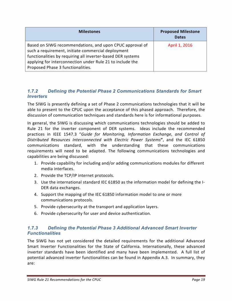
Based on SIWG recommendations, and upon CPUC approval of such a requirement, initiate commercial deployment functionalities by requiring all inverter‐based DER systems applying for interconnection under Rule 21 to include the Proposed Phase 3 functionalities.
April 1, 2016
1.7.2 Defining the Potential Phase 2 Communications Standards for Smart Inverters
The SIWG is presently defining a set of Phase 2 communications technologies that it will be able to present to the CPUC upon the acceptance of this phased approach. Therefore, the discussion of communication techniques and standards here is for informational purposes.
In general, the SIWG is discussing which communications technologies should be added to Rule 21 for the inverter component of DER systems. Ideas include the recommended practices in IEEE 1547.3 “Guide for Monitoring, Information Exchange, and Control of Distributed Resources Interconnected with Electric Power Systems”, and the IEC 61850 communications standard, with the understanding that these communications requirements will need to be adapted. The following communications technologies and capabilities are being discussed:
1. Provide capability for including and/or adding communications modules for different media interfaces.
2. Provide the TCP/IP internet protocols.
3. Use the international standard IEC 61850 as the information model for defining the I‐DER data exchanges.
4. Support the mapping of the IEC 61850 information model to one or more communications protocols.
5. Provide cybersecurity at the transport and application layers.
6. Provide cybersecurity for user and device authentication.
1.7.3 Defining the Potential Phase 3 Additional Advanced Smart Inverter Functionalities
The SIWG has not yet considered the detailed requirements for the additional Advanced Smart Inverter Functionalities for the State of California. Internationally, these advanced inverter standards have been identified and many have been implemented. A full list of potential advanced inverter functionalities can be found in Appendix A.3. In summary, they are:

SIWG Rule 21 Recommendations for the CPUC Page 20
Advanced Inverter Functionalities Requiring Communications
1. Provide emergency alarms and information.
2. Provide status and measurements on current energy and ancillary services.
3. Limit maximum real power output at the Point of Common Coupling (PCC) upon a direct command from the utility.
4. Support direct command to disconnect or reconnect.
5. Provide operational characteristics at initial interconnection and upon changes.
6. Test I‐DER software patching and updates.
Advanced Inverter Functionalities Benefiting from Communications
1. Counteract frequency excursions beyond normal limits by decreasing or increasing real power.
2. Counteract voltage excursions beyond normal limits by providing dynamic current support.
3. Limit maximum real power output at the Electrical Connection Point (ECP) or optionally at the PCC to a preset value.
4. Modify real power output autonomously in response to local voltage variations.
5. Set actual real power output at the PCC.
6. Schedule actual or maximum real power output at specific times.
7. Smooth minor frequency deviations by rapidly modifying real power output to these deviations.
8. Follow schedules for energy and ancillary service outputs.
9. Set or schedule the storage of energy for later delivery, indicating time to start charging, charging rate and/or “charge‐by” time.
SIWG Rule 21 Recommendations for the CPUC 21
2. Proposed Phase 1: Detailed Autonomous Inverter Functionalities Recommended as Technical Operating Standards within Electric Tariff Rule 21
The requirements, default settings, and ranges of setting values for the Phase 1 autonomous I‐DER functionalities are described in the following subsections.
2.1 Anti-Islanding Protection
2.1.1 Purpose of Anti-Islanding Protection
Anti‐islanding protection requires I‐DER systems to disconnect or otherwise cease to energize an unintentionally created electrical island when the Area Electric Power System (EPS) is de‐energized, with the purpose of ensuring the safety of personnel and equipment that might come in contact with that electrical island.
2.1.2 Current Rule 21 Requirements for Anti-Islanding
Rule 21 identifies the anti‐islanding protection requirements in IEEE 1547, including the clearing times for voltage and frequency abnormal conditions.
An additional condition is included in Rule 21 that permits the use of reverse‐power relaying at the PCC as positive anti‐islanding protection for non‐export facilities (G.1.i.Option 1).
2.1.3 Issues with Current Rule 21 Anti-Islanding Requirements
The current Rule 21 anti‐islanding requirements, reflecting the voltage and frequency disconnection requirements in IEEE 1547, do not permit the voltage ride‐through and frequency ride‐through functions which are being recommended (see Section 2.2 Low/High Voltage Ride‐Through (L/HVRT) and Section 2.3 Low/High Frequency Ride‐Through (L/HFRT) of this document).
I‐DER systems can meet the recommended anti‐islanding ride‐through requirements as a separate function. However, there may be anti‐islanding issues if the additional recommended volt/var capabilities (see Section 2.4 Dynamic Volt/Var Operations) are activated. The primary issue caused by the dynamic volt/var function is how I‐DER systems can detect potential islands.
Currently I‐DER systems use a number of methods for detecting possible unintentional islanding situations, including “pushing” against the grid to determine to what degree it resists voltage and/or frequency changes; either the grid is “stiff” (not islanded) or “movable” (possibly islanded). However, if the dynamic volt/var function is activated, then this islanding detection method may not work in all cases.

SIWG Rule 21 Recommendations for the CPUC 22
Some possible new methods have been proposed that would coordinate between anti‐islanding and volt/var functions. One new method would establish a longer time and a larger voltage change (termed a deadband) that would have to take place before the volt/var function responds to voltage anomalies, thus giving the anti‐islanding function time to detect a possible island. Other methods have also been proposed involving a communications signal from utility substations (permissive volt/var signal) whose loss could indicate a power system problem and would deactivate the volt/var function.
From such discussions, one thing is clear: additional study efforts are needed to determine the best methods and optimal volt/var settings to ensure that anti‐islanding operates correctly.
2.1.4 Proposed Anti-Islanding Requirements for Rule 21
Although the Rule 21 requirement to protect the Area EPS from unintentional islanding remains the same, the SIWG proposes that the islanding settings be changed to those identified in Section 2.2 Low/High Voltage Ride‐Through (L/HVRT) and Section 2.3 Low/High Frequency Ride‐Through (L/HFRT) of this document.
The SIWG proposes that certification testing continue to meet the existing anti‐islanding protection requirements in Rule 21, except the references to the disconnect clearing time settings in IEEE 1547 Section 4.2.3 Voltage and Section 4.2.4 Frequency are replaced by the new settings in this document’s proposed High/Low Voltage Ride‐Through Section 2.1.6 and the High/Low Frequency Ride‐Through Section 2.3.
2.1.5 Proposed Rule 21 Text Modifications for Anti-Islanding
The SIWG proposes that Rule 21 Section H.1.a.(2) be revised to reflect the new ride‐through settings in sections 2.2 and 2.3.
2.1.6 Benefits of the Proposed New Anti-Islanding Requirements
The proposed expansion of high and low voltage and frequency protection limits will permit the I‐DER systems to ride through temporary voltage or frequency anomalies, thus decreasing the number of unnecessary disconnections by I‐DER systems and possible power outages, since I‐DER systems will no longer disconnect before the anomalous levels have had time to possibly recover and return within their normal limits.
2.2 Low/High Voltage Ride-Through (L/HVRT)
2.2.1 Purpose of L/HVRT
Low/High Voltage Ride‐Through (L/HVRT) refers to the connect/disconnect behavior of the I‐DER systems during anomalous voltage conditions. L/HVRT defines the voltage levels and

SIWG Rule 21 Recommendations for the CPUC 23
time durations during which the I‐DER systems should remain connected to the Area EPS and, similarly, the voltage levels and time durations at which the I‐DER system must disconnect.
The primary purpose of L/HVRT is to require I‐DER systems to continue to operate for longer times during voltage anomalies than is currently allowed in IEEE 1547.
The reason for this proposed change is that a voltage fluctuation, which causes the voltage to go beyond the normal voltage limits, can often return inside the normal range within a short period of time. However, if high amounts of I‐DER generation disconnect during that voltage fluctuation, the voltage may not be able to return to normal, and unnecessary power outages may occur.
2.2.2 Current Rule 21 Requirements for L/HVRT
The current Rule 21, based on the IEEE 1547 requirements, does not permit the L/HVRT function to be used.
2.2.3 Issues with Current Rule 21 L/HVRT
Since the current Rule 21 does not permit the L/HVRT function to be used, it is expected that increasing numbers of unnecessary outages may occur as increased numbers of I‐DER systems are interconnected with the Area EPS. Europeans have recognized this problem, and many of the European country grid codes now require L/HVRT.
In addition, IEEE 1547 is being updated, first as IEEE 1547a to permit extended voltage ride‐through ranges to be used. Secondly, the base IEEE 1547 document is expected to be updated in the near future to include the L/HVRT requirements.
2.2.4 L/HVRT Function Concepts
For low/high voltage ride through, parameters are used to define the “must disconnect” and “must remain connected” zones by setting the voltage‐time pairs for each point (Hx or Lx) in Figure 1. The three types of zones are:
Blue “must disconnect” zone of voltage levels versus time. This zone is defined by a combination of the I‐DER system safety constraints, local regulatory requirements, and any specific operational situations (anti‐islanding requirement).
Pink “remaining connected or disconnecting is allowed” zone of voltage levels versus time. This zone is defined by the area (if any) between the must disconnect and the must remain connected curves.
Yellow “must remain connected” zone of voltage levels versus time. This curve is also defined by a combination of the I‐DER system safety constraints, local regulatory requirements, and any specific operational situations (e.g. microgrid creation
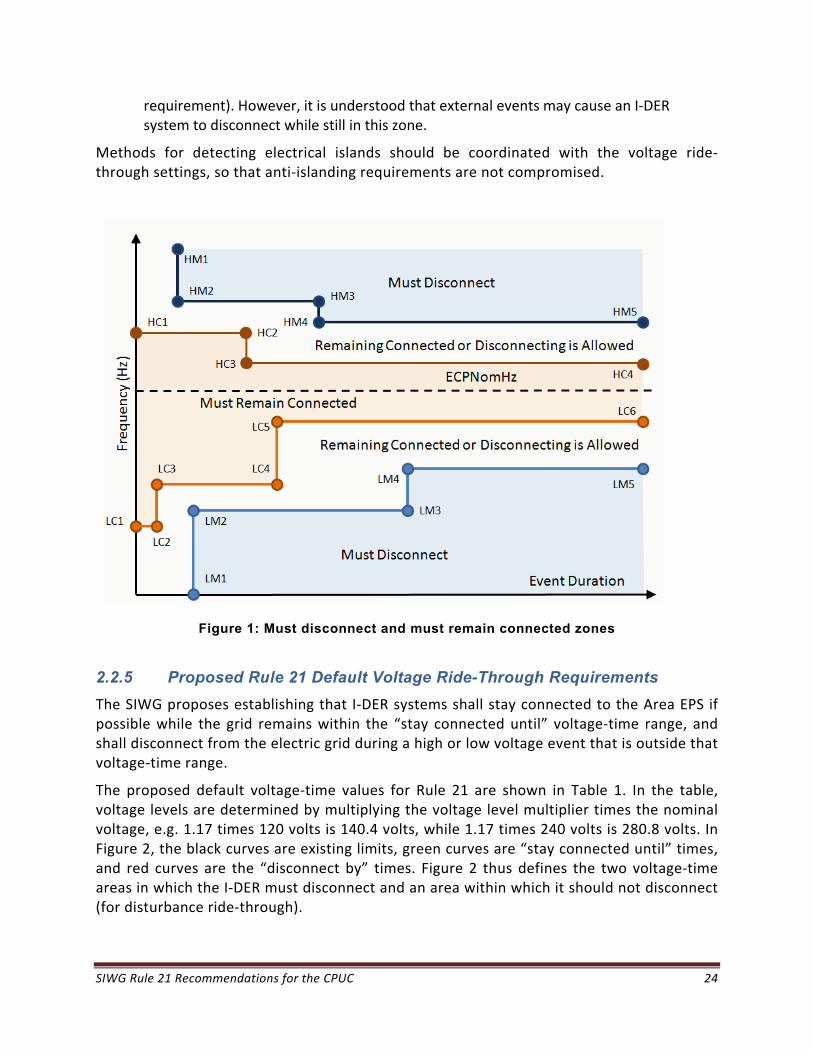
SIWG Rule 21 Recommendations for the CPUC 24
requirement). However, it is understood that external events may cause an I‐DER system to disconnect while still in this zone.
Methods for detecting electrical islands should be coordinated with the voltage ride‐through settings, so that anti‐islanding requirements are not compromised.
Figure 1: Must disconnect and must remain connected zones
2.2.5 Proposed Rule 21 Default Voltage Ride-Through Requirements
The SIWG proposes establishing that I‐DER systems shall stay connected to the Area EPS if possible while the grid remains within the “stay connected until” voltage‐time range, and shall disconnect from the electric grid during a high or low voltage event that is outside that voltage‐time range.
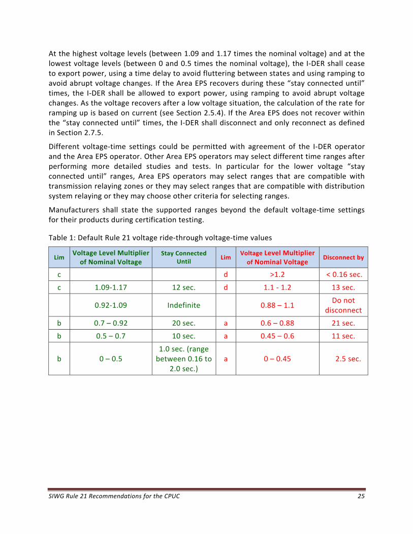
The proposed default voltage‐time values for Rule 21 are shown in Table 1. In the table, voltage levels are determined by multiplying the voltage level multiplier times the nominal voltage, e.g. 1.17 times 120 volts is 140.4 volts, while 1.17 times 240 volts is 280.8 volts. In Figure 2, the black curves are existing limits, green curves are “stay connected until” times, and red curves are the “disconnect by” times. Figure 2 thus defines the two voltage‐time areas in which the I‐DER must disconnect and an area within which it should not disconnect (for disturbance ride‐through).
SIWG Rule 21 Recommendations for the CPUC 25
At the highest voltage levels (between 1.09 and 1.17 times the nominal voltage) and at the lowest voltage levels (between 0 and 0.5 times the nominal voltage), the I‐DER shall cease to export power, using a time delay to avoid fluttering between states and using ramping to avoid abrupt voltage changes. If the Area EPS recovers during these “stay connected until” times, the I‐DER shall be allowed to export power, using ramping to avoid abrupt voltage changes. As the voltage recovers after a low voltage situation, the calculation of the rate for ramping up is based on current (see Section 2.5.4). If the Area EPS does not recover within the “stay connected until” times, the I‐DER shall disconnect and only reconnect as defined in Section 2.7.5.
Different voltage‐time settings could be permitted with agreement of the I‐DER operator and the Area EPS operator. Other Area EPS operators may select different time ranges after performing more detailed studies and tests. In particular for the lower voltage “stay connected until” ranges, Area EPS operators may select ranges that are compatible with transmission relaying zones or they may select ranges that are compatible with distribution system relaying or they may choose other criteria for selecting ranges.
Manufacturers shall state the supported ranges beyond the default voltage‐time settings for their products during certification testing.
Table 1: Default Rule 21 voltage ride‐through voltage‐time values
Lim Voltage Level Multiplier of Nominal Voltage
Stay Connected Until
Lim Voltage Level Multiplier of Nominal Voltage
Disconnect by
c d >1.2 < 0.16 sec.
c 1.09‐1.17 12 sec. d 1.1 ‐ 1.2 13 sec.
0.92‐1.09 Indefinite 0.88 – 1.1 Do not
disconnect
b 0.7 – 0.92 20 sec. a 0.6 – 0.88 21 sec.
b 0.5 – 0.7 10 sec. a 0.45 – 0.6 11 sec.
b 0 – 0.5 1.0 sec. (range between 0.16 to
2.0 sec.) a 0 – 0.45 2.5 sec.
SIWG Rule 21 Recommendations for the CPUC 26
Figure 2: Graph of default voltage ride‐through settings (see table for actual settings)
2.2.6 Proposed Rule 21 Text Modification for L/HVRT
The SIWG proposes that Rule 21 Section H.1.a.(2) and Table H.1 be revised to reflect the new voltage ride‐through settings in this document’s section 2.2.5.
2.2.7 Benefits of the Proposed L/HVRT Requirements
The proposed expansion of high and low voltage protection limits will permit the I‐DER systems to ride through temporary voltage spikes and sags, thus decreasing the number of unnecessary disconnections by I‐DER systems and possible power outages, since I‐DER systems will no longer disconnect before the voltage levels have had time to possibly recover and return within their normal limits.
2.3 Low/High Frequency Ride-Through (L/HFRT)
2.3.1 Purpose of L/HFRT
Low/High Frequency Ride‐Through (L/HFRT) refers to the connect/disconnect behavior of the I‐DER system during frequency deviations. L/HFRT defines the frequency levels and time durations during which the I‐DER system should remain connected to the Area EPS and, similarly, the frequency levels and time durations at which the I‐DER system must disconnect.
The primary purpose of L/HFRT is to require I‐DER systems to continue to operate for longer times during frequency deviations than is currently allowed in IEEE 1547.

SIWG Rule 21 Recommendations for the CPUC 27
The reason for this proposed change is that a frequency fluctuation, which causes the frequency to go beyond the normal frequency limits, can often return inside the normal range within a short period of time. However, if high amounts of I‐DER generation disconnect during that frequency fluctuation, the frequency may not be able to return to normal, and unnecessary power outages may occur.
2.3.2 Current Rule 21 Requirements for L/HFRT
The current Rule 21, based on the IEEE 1547 requirements, does not permit the L/HVRT function to be enabled.
2.3.3 Issues with Current Rule 21 L/HFRT
Since the current Rule 21 does not permit the L/HFRT function to be enabled, it is expected that increasing numbers of unnecessary power outages may occur as increased numbers of I‐DER systems are interconnected with the Area EPS. Such widespread outages might have occurred in Europe, if they had not made expensive retrofits of many I‐DER systems to include L/HFRT. FERC, in its recent Notice of Proposed Rulemaking (NOPR) RM13‐2‐000, item 46,14 also identified this potential problem of I‐DER systems tripping during low/high frequency events, and recommends preventing automatic disconnections.
In addition, IEEE 1547 is being updated, first as IEEE 1547a to permit extended frequency ride‐through ranges to be used. Secondly, the base IEEE 1547 document is expected to be updated in the near future to include the L/HFRT requirements.
2.3.4 L/HFRT Function Concepts
There is no system benefit for having a distributed generating resource disconnect during under‐frequency conditions until the grid frequency goes below 57 Hz when most conventional resources will have disconnected. (For island systems such as in Hawaii or Catalina, even this may be reduced to 56 Hz.) For over frequency conditions, it is believed that system stability would be enhanced by ramping down I‐DER output from its normal levels near 60 Hz to zero near 61 Hz (and back up again as frequency decreases).
Faults will cause temporary phase shifts and changes to zero crossing times, which may be misinterpreted as frequency change. I‐DER control and protection systems should be designed to discriminate between these events and act appropriately.
14 RM13‐2‐000, item 46 “While the German government has ordered the retrofit of thousands of PV systems at significant cost to address its frequency issue, the Commission proposes to prevent such problems with frequency now to mitigate this risk. The proposed revisions to section 1.5.4 of the pro forma SGIA will require the Interconnection Customer to design, install, maintain, and operate its Small Generating Facility, in accordance with the latest version of the applicable standards (IEEE1547 and UL 1741) to prevent automatic disconnection during an over‐ or under‐frequency event and to ensure that rates remain just and reasonable.”
SIWG Rule 21 Recommendations for the CPUC 28
Methods for detecting electrical islands should be coordinated with the frequency ride‐through settings, so that anti‐islanding requirements are not compromised.
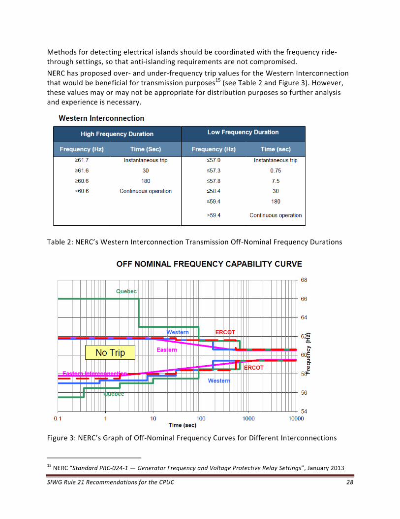
NERC has proposed over‐ and under‐frequency trip values for the Western Interconnection that would be beneficial for transmission purposes15 (see Table 2 and Figure 3). However, these values may or may not be appropriate for distribution purposes so further analysis and experience is necessary.
Table 2: NERC’s Western Interconnection Transmission Off‐Nominal Frequency Durations
Figure 3: NERC’s Graph of Off‐Nominal Frequency Curves for Different Interconnections
15 NERC “Standard PRC‐024‐1 — Generator Frequency and Voltage Protective Relay Settings”, January 2013
SIWG Rule 21 Recommendations for the CPUC 29
2.3.5 Proposed Rule 21 Default Frequency Ride-Through Requirements
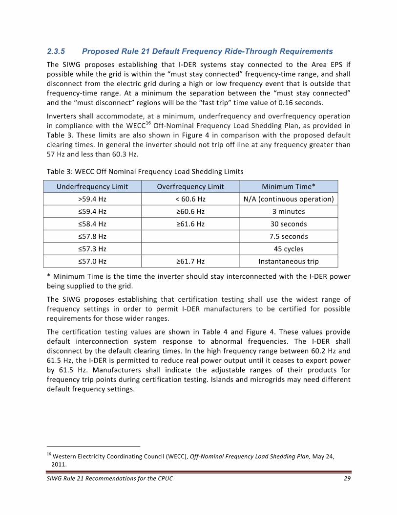
The SIWG proposes establishing that I‐DER systems stay connected to the Area EPS if possible while the grid is within the “must stay connected” frequency‐time range, and shall disconnect from the electric grid during a high or low frequency event that is outside that frequency‐time range. At a minimum the separation between the “must stay connected” and the “must disconnect” regions will be the “fast trip” time value of 0.16 seconds.
Inverters shall accommodate, at a minimum, underfrequency and overfrequency operation in compliance with the WECC16 Off‐Nominal Frequency Load Shedding Plan, as provided in Table 3. These limits are also shown in Figure 4 in comparison with the proposed default clearing times. In general the inverter should not trip off line at any frequency greater than 57 Hz and less than 60.3 Hz.
Table 3: WECC Off Nominal Frequency Load Shedding Limits
Underfrequency Limit Overfrequency Limit Minimum Time*
>59.4 Hz < 60.6 Hz N/A (continuous operation)
≤59.4 Hz ≥60.6 Hz 3 minutes
≤58.4 Hz ≥61.6 Hz 30 seconds
≤57.8 Hz 7.5 seconds
≤57.3 Hz 45 cycles
≤57.0 Hz ≥61.7 Hz Instantaneous trip
* Minimum Time is the time the inverter should stay interconnected with the I‐DER power being supplied to the grid.
The SIWG proposes establishing that certification testing shall use the widest range of frequency settings in order to permit I‐DER manufacturers to be certified for possible requirements for those wider ranges.
The certification testing values are shown in Table 4 and Figure 4. These values provide default interconnection system response to abnormal frequencies. The I‐DER shall disconnect by the default clearing times. In the high frequency range between 60.2 Hz and 61.5 Hz, the I‐DER is permitted to reduce real power output until it ceases to export power by 61.5 Hz. Manufacturers shall indicate the adjustable ranges of their products for frequency trip points during certification testing. Islands and microgrids may need different default frequency settings.
16 Western Electricity Coordinating Council (WECC), Off‐Nominal Frequency Load Shedding Plan, May 24, 2011.

SIWG Rule 21 Recommendations for the CPUC 30
Table 4: Default interconnection system response to abnormal frequencies
System frequency
Default Frequency settings (Hz)
Range of adjustability (Hz)
Default clearing time (s)
Range of adjustability (s)
f > 62 > 62 62 ‐ 64 0.16 0 ‐ 300
60.0 < f < 62 60.5 60 ‐ 62 300 0 ‐ 300
58.5 < 60.5 indefinite
57.0 < f < 58.5 58.5 57 ‐ 60 300 0 – 600
f < 57.0 57 53 ‐ 57 0.16 0 ‐ 5
Figure 4: Graph of default frequency parameters (see tables for detailed settings and ranges)
2.3.6 Proposed Rule 21 Text Modification for L/HFRT
The SIWG proposes that Rule 21 Section H.1.a.(2) and Table H.2 be revised to reflect the new frequency ride‐through settings in this document’s Section 2.3.5.
2.3.7 Benefits of the Proposed L/HFRT Requirements
The proposed expansion of high and low frequency protection limits will permit the I‐DER systems to ride through temporary frequency rises and dips, thus decreasing the number of unnecessary disconnections by I‐DER systems and possible power outages, since I‐DER

SIWG Rule 21 Recommendations for the CPUC 31
systems will no longer disconnect before the frequency levels have had time to possibly recover and return within their normal limits.
2.4 Dynamic Volt/Var Operations
2.4.1 Purpose of Dynamic Volt/Var Operations
Dynamic volt/var operations, also called dynamic reactive power compensation, allow I‐DER systems to counteract voltage deviations from the nominal voltage level (but still within normal operating ranges) by consuming or producing reactive power.17 Dynamic volt/var “curves” are defined that specify the changes in vars in response to changes in the local voltage measured by the I‐DER system (see Figure 5).
The purpose of volt/var operations is to use I‐DER systems to help maintain voltage levels within their normal ranges. This capability can be particularly important for I‐DER systems (and aggregations of I‐DER systems) that may impact the normal voltage range on a feeder, such as those at the end of long, electrically “weak” circuits.18 However, dynamic volt/var operations could be used for other purposes such as helping to maintain conservation voltage reduction (CVR) levels.
2.4.2 Current Rule 21 Requirements for Dynamic Volt/Var Operations
Rule 21 permits setting the power factor of a I‐DER system to a static value, but it does not permit dynamic volt/var operations, based on the IEEE 1547 constraint that the I‐DER system cannot actively regulate the voltage at the PCC.
2.4.3 Issues with Current Rule 21 Dynamic Volt/Var Operations
Preventing dynamic volt/var operations limits the capability to use I‐DER systems to improve the efficiency of the Area EPS. In addition, IEEE 1547 is being updated, first as IEEE 1547a to permit active regulation of voltage at the PCC. Secondly, the base IEEE 1547 document is expected to be updated in the near future and may include additional dynamic volt/var requirements, possibly based on those proposed in this document for Rule 21.
2.4.4 Dynamic Volt/Var Operations Concepts
The amount of reactive power can be established by a “curve” defining voltage versus percentage of reactive power. Percentage of reactive power can be calculated as:
17 Reactive power is measured in volt‐ampere reactive units (vars). 18 Weakness and strength of circuits is determined by their “stiffness”, defined as the ability of an Area EPS to resist voltage deviations caused by the DER system.

SIWG Rule 21 Recommendations for the CPUC 32
Percentage of available reactive power for the measured percentage of the reference voltage. “Available vars” implies the consumption or production of reactive power that does not affect the real power output.
Percentage of maximum reactive power. In this case, consumption or production of reactive power may affect the real power output.
The volt/var curve using available vars is shown In Figure 5, including a deadband between P2 and P3. Hysteresis can be included in the curve to dampen unnecessary swings, as shown in Figure 6.
Figure 5: Example settings of volt/var mode using available vars and a deadband around the nominal voltage (P2‐P3)
Figure 6: Example of volt/var curve with hysteresis, with arrows indicating direction of voltage changes
2.4.5 Proposed Rule 21 Default Dynamic Volt/Var Operation Requirements
The SIWG proposes establishing that the I‐DER system be capable of operating dynamically within a power factor (defined as cos φ between voltage and current) range of +/‐ 0.85 PF
VA
Rs
Ge
ner
ate
d
System Voltage
Voltage-Rising/FallingP1 (V = 97%VRef , Q = 50%VArAval )
P2 (V = 99%VRef, Q = 0%VArAval)
P3 (V = 101%VRef, Q = 0%VArAval)
P4 (V = 103%VRef , Q = -50%VArAval )
Example settings for providing % of available vars
Inductive/Underexcited
Capacitive/Overexcited

SIWG Rule
for large(<15 kWillustratedeactiva
I‐DER syquadranTesting ovoluntar
Figure 7:
The SIWpower ina decrealine voltcurve to
The SIWGreactive
Tco
Tra
19 The termused in Iare all in
e 21 Recomme
er (>15 kW) W), down toed in Figureted.
ystems are t operationof these laily be perfo
: P‐Q capabi
WG proposesn response tase in line voage to reacminimize u
G proposes power com
he I‐DER sysoupling to go
he full Rangather than li
ms in the diagEC 61850‐90‐n agreement
endations for t
systems, doo 20% of rae 7. This dy
permitted s for storagrger permisrmed durin
ility curve (P
s establishinto an increaoltage. In gective powernnecessary
establishingpensation (
stem output o outside th
e A should bmiting it to t
ram, “underex7, since often
the CPUC
own to 5% oted power,ynamic volt
to operatege systems, ssive rangesg Phase 1.
P: real powe
ng that the se in line voeneral, a cur output. Hychanges. Se
g that the I‐dynamic vo
shall not cae requireme
be allowed fothe lower ra
xcited”, “overthese terms a
of rated pow, based on t/var capab
e in larger possibly wits will be pa
er; Q: reacti
I‐DER systeoltage, and rve shall beysteresis anee Figures in
‐DER systemolt/var opera
use the line ents of the la
or distributioange for CVR
rexcited”, “indare used diffe
wer, and +/‐available v
bility shall b
power factth additionaart of Phas
ive power; S
em shall beproduce reae establishednd deadbann Section 2.
m shall be caation) withi
voltage at tatest version
on feeders wR.
d.”, and “cap.”rently by diffe
‐ 0.9 PF for vars, as parbe able to
tor ranges, al anti‐islanse 3, but th
S: apparent
e able to coactive powed that corrends may be .4.1.
apable of prn the follow
the point of cn of ANSI C8
with custom
” are differenterent groups,
smaller sysrt of Phase be activate
including nding protechis testing c
power)19
onsume reaer in responelates changincluded in
roviding dynwing constra
common 84.1, Range A
er generatio
t from the termbut the conce
33
tems 1 as
ed or
in 4‐ction. could
active se to ges in n the
namic aints:
A.
on,
ms epts
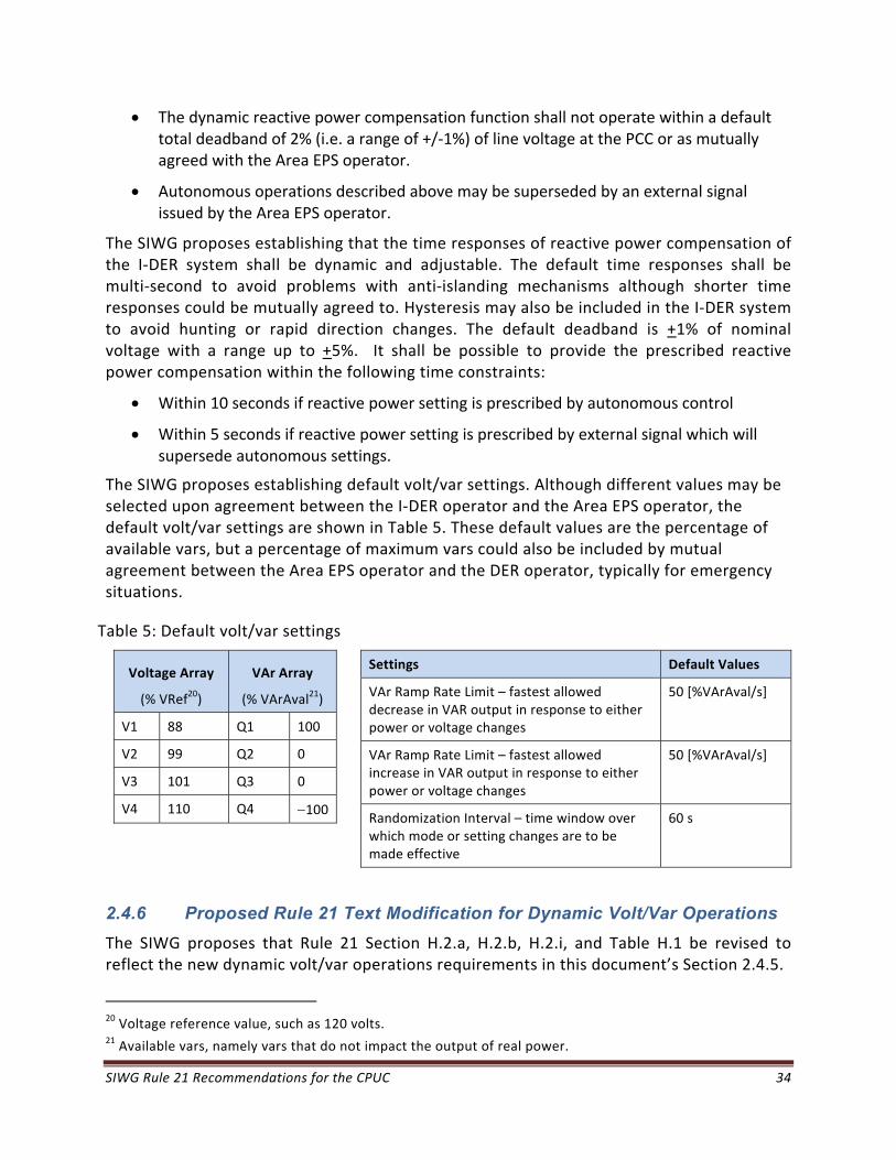
SIWG Rule 21 Recommendations for the CPUC 34
The dynamic reactive power compensation function shall not operate within a default total deadband of 2% (i.e. a range of +/‐1%) of line voltage at the PCC or as mutually agreed with the Area EPS operator.
Autonomous operations described above may be superseded by an external signal issued by the Area EPS operator.
The SIWG proposes establishing that the time responses of reactive power compensation of the I‐DER system shall be dynamic and adjustable. The default time responses shall be multi‐second to avoid problems with anti‐islanding mechanisms although shorter time responses could be mutually agreed to. Hysteresis may also be included in the I‐DER system to avoid hunting or rapid direction changes. The default deadband is +1% of nominal voltage with a range up to +5%. It shall be possible to provide the prescribed reactive power compensation within the following time constraints:
Within 10 seconds if reactive power setting is prescribed by autonomous control
Within 5 seconds if reactive power setting is prescribed by external signal which will supersede autonomous settings.
The SIWG proposes establishing default volt/var settings. Although different values may be selected upon agreement between the I‐DER operator and the Area EPS operator, the default volt/var settings are shown in Table 5. These default values are the percentage of available vars, but a percentage of maximum vars could also be included by mutual agreement between the Area EPS operator and the DER operator, typically for emergency situations.
Table 5: Default volt/var settings
Voltage Array
(% VRef20)
VAr Array
(% VArAval21)
V1 88 Q1 100
V2 99 Q2 0
V3 101 Q3 0
V4 110 Q4 100
Settings Default Values
VAr Ramp Rate Limit – fastest allowed decrease in VAR output in response to either power or voltage changes
50 [%VArAval/s]
VAr Ramp Rate Limit – fastest allowed increase in VAR output in response to either power or voltage changes
50 [%VArAval/s]
Randomization Interval – time window over which mode or setting changes are to be made effective
60 s
2.4.6 Proposed Rule 21 Text Modification for Dynamic Volt/Var Operations
The SIWG proposes that Rule 21 Section H.2.a, H.2.b, H.2.i, and Table H.1 be revised to reflect the new dynamic volt/var operations requirements in this document’s Section 2.4.5.
20 Voltage reference value, such as 120 volts. 21 Available vars, namely vars that do not impact the output of real power.
SIWG Rule 21 Recommendations for the CPUC 35
2.4.7 Benefits of the Proposed Dynamic Volt/Var Operations Requirements
Permitting active voltage regulation will allow I‐DER systems to compensate for any voltage impacts that their generation might have on the circuit, and can also help maintain conservation voltage reduction (CVR) voltage levels and stabilize voltage deviations caused by other I‐DER systems and loads.
2.5 Ramp Rates
2.5.1 Purpose of Ramp Rates
I‐DER systems can ramp the rate of increasing and/or decreasing their power output. These ramp rates are constrained by what the I‐DER systems can physically do. For instance, if they are outputting their maximum power, they can ramp down but cannot ramp up, while a completely charged storage system may ramp up (discharge power into the Area EPS) but cannot ramp down.
The purpose of establishing ramp‐up and ramp‐down rates for I‐DER systems is to help in smoothing out the transitions from one output level to another output level. Although a single I‐DER system might not impact the grid through a single sharp transition, aggregated I‐DER systems responding to a specific event could cause significant rapid jumps in overall output if they do not ramp to the new level. Such sharp transitions could cause power quality issues such as voltage spikes or dips, harmonics, or oscillations.
2.5.2 Current Rule 21 Requirements for Ramp Rates
Neither Rule 21 nor IEEE 1547 addresses ramp rates.
2.5.3 Issues with Current Rule 21 on Ramp Rates
Since Rule 21 does not address ramp rates, it would not be possible for specific ramp rates to be required under different situations.
2.5.4 Proposed Ramp Rate Requirements
The SIWG proposes establishing at least three types of ramp‐up rates for use by different functions, although they may optionally be implemented as one general ramp rate. Ramp rates are contingent upon sufficient energy available from the I‐DER. Manufacturers can indicate the types of ramp‐up rates provided in their products during certification testing:
“Normal ramp‐up rate”: For transitions between energy output levels. The default value is 100% of maximum current output per second22, with a range of adjustment between 0.1%/sec to 100%/sec or with a range as specified by the manufacturer.
22 IEC 61850‐7‐420 ramp rates will be updated from minutes to seconds

SIWG Rule 21 Recommendations for the CPUC 36
“Emergency ramp‐up rate”: For emergency conditions, including after a power system event. The default value is 2% of maximum energy output per second or the maximum ramp rate supported by the I‐DER, whichever is less.
“Soft‐start connect ramp‐up rate”: For use when a disconnected I‐DER system is reconnected to the Area EPS. The default value is 2% of maximum current output per second, with a range of adjustment between 0.1%/sec to 100%/sec or with a range as specified by the manufacturer.
The SIWG proposes establishing at least three ramp‐down rates shall be established for use by different functions, although they may optionally be implemented as one general ramp rate. Manufacturers shall indicate the types of ramp‐down rates provided in their products during certification testing:
“Normal ramp‐down rate”: Established for transitions between energy output levels, The default value is 100% of maximum current output per second, with a range of adjustment between 0.1%/sec to 100%/sec or with a range as specified by the manufacturer.
“Emergency ramp‐down rate”: May be used under emergency conditions. The default value is 2% of maximum current output per second with a range of adjustment between 0.1%/sec to 100%/sec, or with a range as specified by the manufacturer or the maximum ramp rate supported by the I‐DER, whichever is less.
“Soft disconnect ramp‐down rate”: Used if possible whenever the I‐DER system disconnects from the Area EPS in non‐emergency situations. The default value is 2% of maximum current output per second, with a range of adjustment between 0.1%/sec to 100%/sec or with a range as specified by the manufacturer.
2.5.5 Proposed Rule 21 Text Modification for Ramp Rates
The SIWG proposes that a new sub‐section within Rule 21, Section H include the proposed new ramp rate requirements in this document’s Section 2.5.4.
2.5.6 Benefits of the Proposed Ramp Rate Requirements
Establishing the use of ramp rates for moving from one output level to another will help avoid sharp transitions and the consequential power quality problems of voltage spikes or dips, harmonics, and oscillations.
SIWG Rule 21 Recommendations for the CPUC 37
2.6 Fixed Power Factor
2.6.1 Purpose of Fixed Power Factor (PF)
The most efficient operation of an Area EPS is if it has zero reactive power, and thus has the optimal power factor (PF) of 1.0. However different types of loads and I‐DER systems can generate reactive power, thus lowering the PF below the optimal value of 1.0.
The purpose of establishing fixed power factors in I‐DER systems is to help compensate for those loads and other I‐DER systems that generate reactive power. If, on average, a circuit has a power factor of +0.95, then some of the I‐DER systems on that circuit can be set to have a power factor of ‐0.95.
2.6.2 Current Rule 21 Requirements for Fixed Power Factor
Rule 21 does permit fixed power factors to be set by the I‐DER systems and/or by the Area EPS operator, but currently limits the power factor values to be between ‐0.9 and +0.9.
2.6.3 Issues with the Current Rule 21 Requirement for Fixed Power Factor
The current limits to the power factor values prevent wider ranges to be requested if they are needed.
2.6.4 Fixed Power Factor Concepts
I‐DER systems can establish a fixed power factor that can help offset loads and other DER systems that cause the circuit’s power factor to deviate from the optimal value of 1.0.
Although the autonomous fixed power factor must be preset, it is expected that in subsequent phases, this fixed power factor value could be modified for some I‐DER systems through communications.
2.6.5 Proposed Fixed Power Factor Requirements
The SIWG proposes establishing that the I‐DER system be capable of operating at a fixed power factor with the default value of 1.0 +.01 within the power factor ranges defined in Section 2.4.5.
2.6.6 Proposed Rule 21 Text Modification
The SIWG proposes that Rule 21 Section H.2.i be revised to reflect the new power factor ranges proposed in this document’s Section 2.6.5.
SIWG Rule 21 Recommendations for the CPUC 38
2.6.7 Benefits of the Proposed Fixed Power Factor Capability
Establishing fixed power factors can help offset different types of loads and the possible impacts of different types of DER systems. This will permit the circuits to better maintain the optimal power factor of 1.0. In particular, when communications are established with I‐DER systems, the fixed power factor value can be adjusted as needed for matching the circuit’s efficiency needs more closely.
2.7 Reconnect by “Soft-Start” Methods
2.7.1 Purpose of Reconnection by “Soft-Start” Methods
Following an outage, when power is restored to the Area EPS, the I‐DER systems on that circuit will need to reconnect to start generating power. If all I‐DER systems started to output real power at exactly the same time, the circuit could experience a sharp transition, which could cause instability, possibly voltage spikes, or even sharp frequency increases.
The purpose of the reconnection by “Soft‐Start” is to ameliorate these sharp transitions by ramping or staggering the reconnections of the I‐DER systems.
2.7.2 Current Rule 21 Requirements on Reconnection
Rule 21 specifies the Area EPS voltage and frequency requirements for reconnection, but does not address “soft‐start” reconnection requirements.
2.7.3 Issues with Current Rule 21 on Reconnection
Although the current Rule 21 does not prevent “soft‐start” reconnection requirements, it also does not establish any specific requirements on how to perform such “soft‐start” reconnections.
2.7.4 “Soft-Start” Reconnection Concepts
After power is restored to a circuit and voltage and frequency have returned within their normal ranges for a specified time period, the I‐DER systems will also reconnect and start operating. If all I‐DER systems started exactly at the same time with a jump in real power output, the circuit could experience a sharp transition which could cause instability and possibly voltage spikes or even sharp frequency increases or oscillations.
Two methods can be used to ameliorate such a sharp transition: either the I‐DER systems ramp up over time to their normal output level, or they randomly reconnect within a time window of a few minutes.
The delay time between power restoration and the reconnection of I‐DER systems could also be different depending upon whether the outage was momentary (e.g. less than 5 minutes) or long (e.g. greater than 5 minutes).

SIWG Rule 21 Recommendations for the CPUC 39
2.7.5 Proposed Rule 21 Reconnection Requirements
The SIWG proposes the following I‐DER reconnection requirements. The I‐DER system determines that the Area EPS is available for reconnection and assures that both the voltage level and the frequency are within the normal ANSI B ranges. After the I‐DER has disconnected for any length of time, the I‐DER system delays reconnecting until the voltage and frequency have remained with ANSI B range for a default delay time of 15 seconds. The range of the delay time is the same as in IEEE 1547:2003, namely any time within 0‐5 minutes or for a fixed 5 minutes. The I‐DER system then reconnects to the Area EPS after power is restored and voltage and frequency measurements are within the allowable range for the specified delay time. This reconnection shall use one (or both) of two soft‐start methods:
Ramping up: The I‐DER ramps up according to the reconnect ramp‐up rate as defined in the Ramp Rates in section 2.5.4.
Randomly within a time window: The I‐DER connects randomly within a time window. If the time window is zero, the I‐DER system will reconnect immediately. The default time window is 15 seconds, with a range of 0 to 30 seconds.
2.7.6 Proposed Rule 21 Text Modifications for “Soft-Start” Reconnection
The SIWG proposes that Rule 21 Section H.1.a.(2) be revised to reflect the reconnection requirements in this document’s Section 2.7.5.
2.7.7 Benefits of the Proposed “Soft-Start” Reconnection
By either requiring I‐DER systems to ramp up during reconnection or to reconnect randomly within a time window, the sharp transitions and consequential power quality problems of voltage spikes, harmonics, and oscillations can be avoided, including the possibility that the disruptions caused by the reconnection of large numbers of I‐DER systems actually precipitates another power outage.
2.8 Phase 1 I-DER System Parameters and Monitored Points
2.8.1 Phase 1 I-DER Parameters for Manufacturers
For the convenience of manufacturers, definitions of I‐DER parameters are defined in Table 6. It is understood that there may be many other parameters needed by different manufacturers for different types of I‐DER systems, so this list just contains the basic parameters needed for describing the Phase 1 functions. Some of these parameters will necessarily be mandatory to provide the Phase 1 functions, but many will be optional, depending upon the methods used to implement the functions. The main proviso is that if a particular parameter is used, it should be implemented as having the same definition as included in this list.

SIWG Rule 21 Recommendations for the CPUC 40
The parameter names are for convenience in referencing, although there is a strong correlation with IEC 61850 names. These I‐DER parameters are shown in Table 6.
Table 6: Phase 1 I‐DER Parameters
Parameter name Description Example Values
WMax
The maximum watts that the I‐DER system would be able to output. This is a settable limit that may be the same as the nameplate value, or may be (typically) a lower value reflecting actual implementation limit.
14,500 W
WChaMax
The maximum watts that the storage I‐DER system would be able to store. This is a settable limit that may be the same as the nameplate value, or may be (typically) a lower value reflecting actual implementation limit.
14,500 W
VAMax
The maximum volt‐amps that the I‐DER system would be able to provide. This is a settable limit that may be the same as the nameplate value, or may be (typically) a lower value reflecting actual implementation limit.
16,000 VA
VAChaMax
The maximum volt‐amps that the storage I‐DER system would be able to store. This is a settable limit that may be the same as the nameplate value, or may be (typically) a lower value reflecting actual implementation limit.
16,000 VA
VArMax
The maximum VArs that the I‐DER system would be able to provide. This is a settable limit that may be the same as the nameplate value, or may be (typically) a lower value reflecting actual implementation limit.
12,000 VAR
CtlHzHiLim The hard high frequency limit, as setpoint for the upper level of Hz allowed for the I‐DER system.
63.2 Hz
CtlHzLoLim The hard low frequency limit, as setpoint for the lower level of Hz allowed for the I‐DER system.
56.3 Hz
VRef The reference voltage or nominal voltage 120 V
VRefOfs The offset from the reference voltage due to the electrical location of the I‐DER system. This may be a setting or may be calculated dynamically from local voltage measurements.
2 V
WGra
The default ramp rate of change of active power output, that will be used if possible. Additional types of ramp rates may also exist, such as the reconnect ramp rate or specified ramp rates in commands or schedules.
20 % WMax/second
WChaGra
The default charging ramp rate for storage devices that will be used if possible. Additional types of ramp rates may also exist, such as an emergency ramp rate or specified ramp rates in commands or schedules.
15 % WChaMax/second
PFsign (optional) Power factor: sign convention 1 = IEC; 2 = EEI;
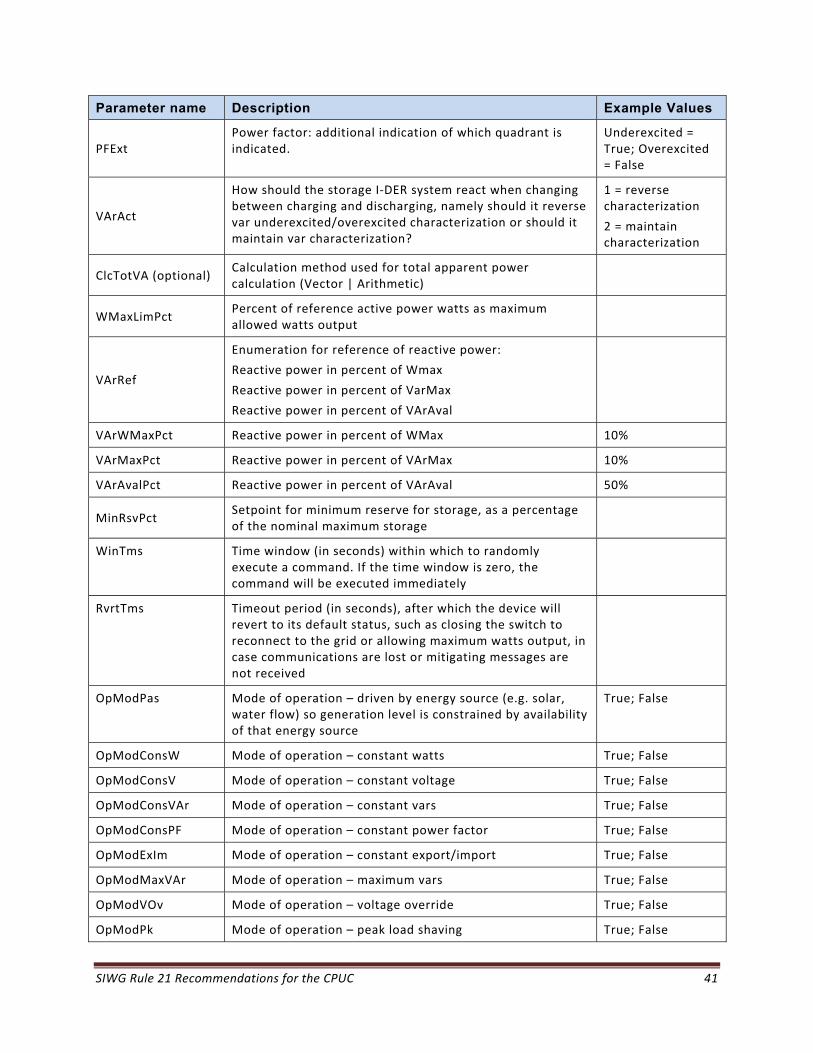
SIWG Rule 21 Recommendations for the CPUC 41
Parameter name Description Example Values
PFExt Power factor: additional indication of which quadrant is indicated.
Underexcited = True; Overexcited = False
VArAct
How should the storage I‐DER system react when changing between charging and discharging, namely should it reverse var underexcited/overexcited characterization or should it maintain var characterization?
1 = reverse characterization
2 = maintain characterization
ClcTotVA (optional) Calculation method used for total apparent power calculation (Vector | Arithmetic)
WMaxLimPct Percent of reference active power watts as maximum allowed watts output
VArRef
Enumeration for reference of reactive power:
Reactive power in percent of Wmax
Reactive power in percent of VarMax
Reactive power in percent of VArAval
VArWMaxPct Reactive power in percent of WMax 10%
VArMaxPct Reactive power in percent of VArMax 10%
VArAvalPct Reactive power in percent of VArAval 50%
MinRsvPct Setpoint for minimum reserve for storage, as a percentage of the nominal maximum storage
WinTms Time window (in seconds) within which to randomly execute a command. If the time window is zero, the command will be executed immediately
RvrtTms Timeout period (in seconds), after which the device will revert to its default status, such as closing the switch to reconnect to the grid or allowing maximum watts output, in case communications are lost or mitigating messages are not received
OpModPas Mode of operation – driven by energy source (e.g. solar, water flow) so generation level is constrained by availability of that energy source
True; False
OpModConsW Mode of operation – constant watts True; False
OpModConsV Mode of operation – constant voltage True; False
OpModConsVAr Mode of operation – constant vars True; False
OpModConsPF Mode of operation – constant power factor True; False
OpModExIm Mode of operation – constant export/import True; False
OpModMaxVAr Mode of operation – maximum vars True; False
OpModVOv Mode of operation – voltage override True; False
OpModPk Mode of operation – peak load shaving True; False

SIWG Rule 21 Recommendations for the CPUC 42
Parameter name Description Example Values
OpModIsld Mode of operation – islanded at the ECP True; False
OpModPrc Mode of operation – pricing signal True; False
OpModVrt Mode of operation – voltage ride‐through True; False
OpModFrt Mode of operation – frequency ride‐through True; False
OpModVVAr Mode of operation – dynamic volt/var mode True; False
Voltage ride‐through arrays
High voltage must disconnect array of voltage vs. time
High voltage must stay connected array of voltage vs. time
Low voltage must stay connected array of voltage vs. time Low voltage must disconnect array of voltage vs. time
4 arrays;
10 pairs of v‐t settings each
Frequency ride‐through arrays
High frequency must disconnect array of frequency vs. time
High frequency must stay connected array of frequency vs. time
Low frequency must stay connected array of frequency vs. time Low frequency must disconnect array of frequency vs. time
4 arrays;
6 pairs of f‐t settings each
Dynamic volt/var arrays
Voltage vs. vars array
Deadband array for each volt/var segment
Hysteresis volt/var array
2 arrays;
4 pairs of v‐var settings with deadbands for forward hysteresis;
4 pairs of v‐var settings for return hysteresis
RampTms Ramp time, in seconds, for moving from current operational settings to new operational mode settings
1 second
RampRte Default ramp up or down rate for transitions between output power levels (constrained by DER capabilities), power versus time
100% of max current output per second
NomUpRamp (optional)
Nominal ramp up rate if separate up and down ramp rates are required
100% of max current output per second
NomDnRamp (optional)
Nominal ramp down rate if separate up and down ramp rates are required
100% of max current output per second
EmgRampUpRtg Emergency ramp up rate 2% of max current output per second
ConnRampDnRtg (optional)
Disconnection ramp down rate (non‐emergency) 2% of max current output per second
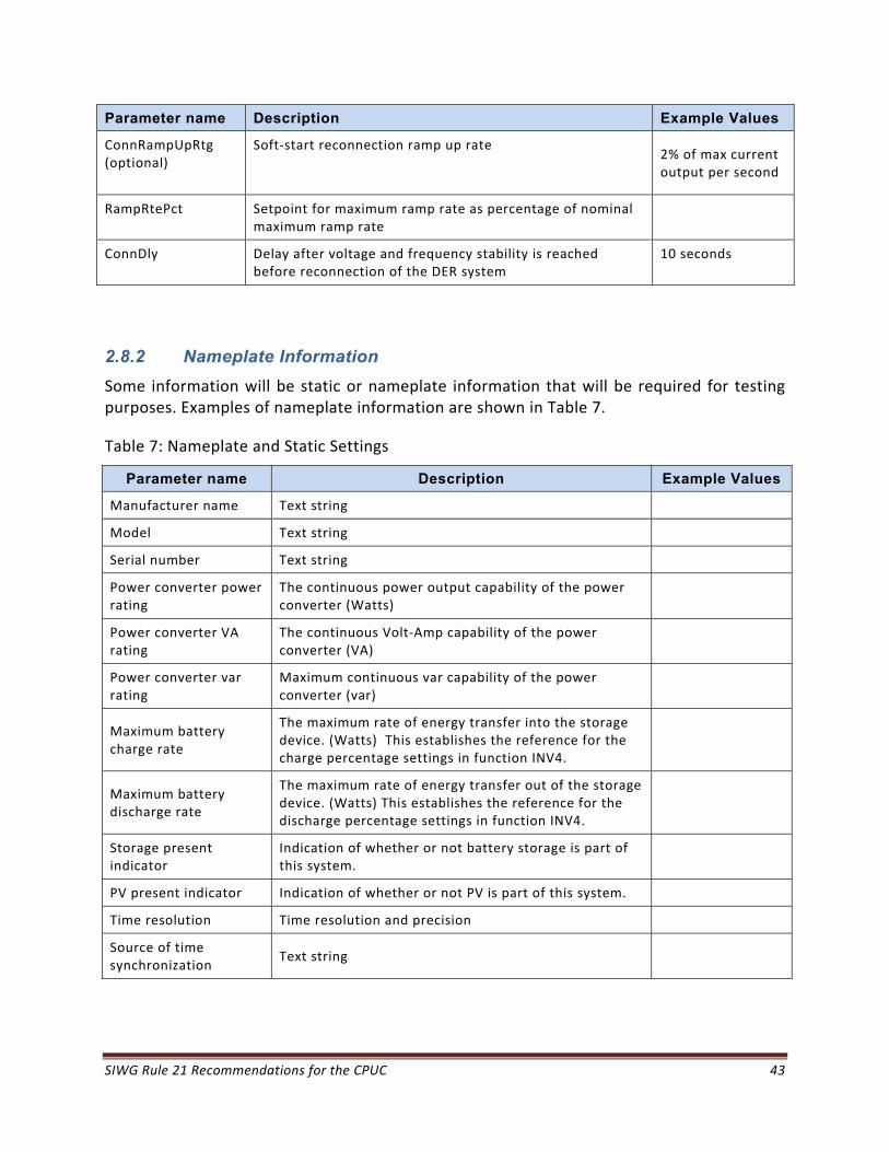
SIWG Rule 21 Recommendations for the CPUC 43
Parameter name Description Example Values
ConnRampUpRtg (optional)
Soft‐start reconnection ramp up rate 2% of max current output per second
RampRtePct Setpoint for maximum ramp rate as percentage of nominal maximum ramp rate
ConnDly Delay after voltage and frequency stability is reached before reconnection of the DER system
10 seconds
2.8.2 Nameplate Information
Some information will be static or nameplate information that will be required for testing purposes. Examples of nameplate information are shown in Table 7.
Table 7: Nameplate and Static Settings
Parameter name Description Example Values
Manufacturer name Text string
Model Text string
Serial number Text string
Power converter power rating
The continuous power output capability of the power converter (Watts)
Power converter VA rating
The continuous Volt‐Amp capability of the power converter (VA)
Power converter var rating
Maximum continuous var capability of the power converter (var)
Maximum battery charge rate
The maximum rate of energy transfer into the storage device. (Watts) This establishes the reference for the charge percentage settings in function INV4.
Maximum battery discharge rate
The maximum rate of energy transfer out of the storage device. (Watts) This establishes the reference for the discharge percentage settings in function INV4.
Storage present indicator
Indication of whether or not battery storage is part of this system.
PV present indicator Indication of whether or not PV is part of this system.
Time resolution Time resolution and precision
Source of time synchronization
Text string
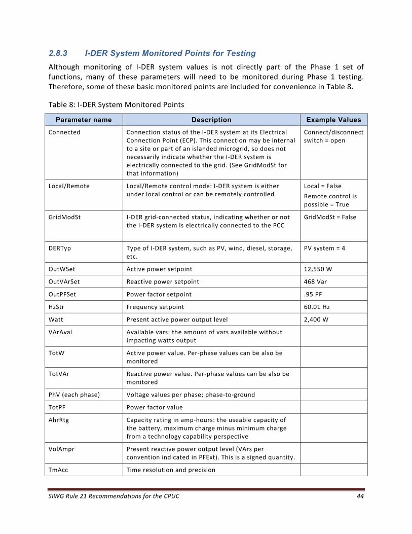
SIWG Rule 21 Recommendations for the CPUC 44
2.8.3 I-DER System Monitored Points for Testing
Although monitoring of I‐DER system values is not directly part of the Phase 1 set of functions, many of these parameters will need to be monitored during Phase 1 testing. Therefore, some of these basic monitored points are included for convenience in Table 8.
Table 8: I‐DER System Monitored Points
Parameter name Description Example Values
Connected Connection status of the I‐DER system at its Electrical Connection Point (ECP). This connection may be internal to a site or part of an islanded microgrid, so does not necessarily indicate whether the I‐DER system is electrically connected to the grid. (See GridModSt for that information)
Connect/disconnect switch = open
Local/Remote Local/Remote control mode: I‐DER system is either under local control or can be remotely controlled
Local = False
Remote control is possible = True
GridModSt I‐DER grid‐connected status, indicating whether or not the I‐DER system is electrically connected to the PCC
GridModSt = False
DERTyp Type of I‐DER system, such as PV, wind, diesel, storage, etc.
PV system = 4
OutWSet Active power setpoint 12,550 W
OutVArSet Reactive power setpoint 468 Var
OutPFSet Power factor setpoint .95 PF
HzStr Frequency setpoint 60.01 Hz
Watt Present active power output level 2,400 W
VArAval Available vars: the amount of vars available without impacting watts output
TotW Active power value. Per‐phase values can be also be monitored
TotVAr Reactive power value. Per‐phase values can be also be monitored
PhV (each phase) Voltage values per phase; phase‐to‐ground
TotPF Power factor value
AhrRtg Capacity rating in amp‐hours: the useable capacity of the battery, maximum charge minus minimum charge from a technology capability perspective
VolAmpr Present reactive power output level (VArs per convention indicated in PFExt). This is a signed quantity.
TmAcc Time resolution and precision
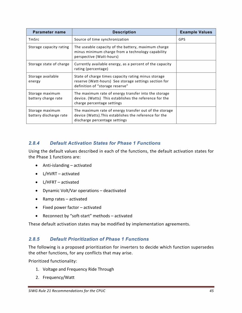
SIWG Rule 21 Recommendations for the CPUC 45
Parameter name Description Example Values
TmSrc Source of time synchronization GPS
Storage capacity rating The useable capacity of the battery, maximum charge minus minimum charge from a technology capability perspective (Watt‐hours)
Storage state of charge Currently available energy, as a percent of the capacity rating (percentage)
Storage available energy
State of charge times capacity rating minus storage reserve (Watt‐hours) See storage settings section for definition of “storage reserve”
Storage maximum battery charge rate
The maximum rate of energy transfer into the storage device. (Watts) This establishes the reference for the charge percentage settings
Storage maximum battery discharge rate
The maximum rate of energy transfer out of the storage device (Watts).This establishes the reference for the discharge percentage settings
2.8.4 Default Activation States for Phase 1 Functions
Using the default values described in each of the functions, the default activation states for the Phase 1 functions are:
Anti‐islanding – activated
L/HVRT – activated
L/HFRT – activated
Dynamic Volt/Var operations – deactivated
Ramp rates – activated
Fixed power factor – activated
Reconnect by “soft‐start” methods – activated
These default activation states may be modified by implementation agreements.
2.8.5 Default Prioritization of Phase 1 Functions
The following is a proposed prioritization for inverters to decide which function supersedes the other functions, for any conflicts that may arise.
Prioritized functionality:
1. Voltage and Frequency Ride Through
2. Frequency/Watt
SIWG Rule 21 Recommendations for the CPUC 46
3. Commanded (set P, limit P)
4. Set PF or Volt/Var, Volt/W
SIWG Rule 21 Recommendations for the CPUC 47
3. Defining the Potential Phase 2 Communications Technologies for I-DER Functions
The SIWG is presently defining a set of Phase 2 communications technologies that it will be able to present to the CPUC upon the acceptance of this phased approach. Therefore, the discussion of communication standards here is for informational purposes.
3.1 Purpose of Communications Technologies for I-DER functions
Although the Proposed Phase 1 I‐DER functions can operate autonomously, they cannot be easily activated and deactivated without communications, while their parameters and software cannot be updated. In addition, some Proposed Phase 3 functions require communications, such as an emergency command from the utility for I‐DER systems to decrease or increase output or even to disconnect from the grid. Communications allows functional and security updates to be issued to the I‐DER systems without the need to physically go to each site.
3.2 Current Rule 21 Requirements for Communications
Currently Rule 21 does not address communications requirements for DER systems beyond what is covered in IEEE 1547. Since the current IEEE 1547 includes very limited communications requirements, it is explicitly “technology neutral” with respect to communication technologies.
However, IEEE 1547.3, the Guide for Monitoring, Information Exchange, and Control of Distributed Resources Interconnected with Electric Power Systems, states “[Monitoring, Information exchange, and Control (MIC)] for DR systems should support interoperability between the DR devices and the area EPS. Interoperability is the ability of two or more devices to exchange information and work together in a system. This is achieved by using published object and data definitions, standard commands, and standard protocols.”
Therefore, to ensure interoperability of the I‐DER functions throughout California, it is necessary to define the communications technologies based on the concepts covered in IEEE 1547.3 and using internationally recognized standards where possible.
In particular, IEEE 1547.3 references the International Electrotechnical Commission (IEC) as the recommended source of communications standards for DER systems. The IEC has developed many of the necessary communications standards which have been adopted and implemented by European and many other countries for their DER systems. The primary communications standard for DER is IEC 61850. The US does not always adopt IEC standards without making some adaptations for US requirements, therefore the IEC 61850 standards are expected to serve as the basis for these communications standards but may result in adaptations for California.
SIWG Rule 21 Recommendations for the CPUC 48
3.3 Problems Created by the Absence of a Statewide Communication Standard for DER Systems
The absence of a statewide communication standard for DER systems in California means that I‐DER systems may offer no communications capability or any of a wide variety of communications protocols. Many systems operating on different communications platforms are not necessarily interoperable. This is a clearly impracticable situation.
The SIWG’s aim is to specify a small set of communications technologies to prevent the need for future retrofitting, to promote interoperability across all implementations, and to optimize the benefits of the smart I‐DER functionalities.
Communications for large numbers of disparate types of I‐DER systems should be based on a small set of well‐designed communications standards that ensure interoperability across all stakeholders. Otherwise there would be a proliferation of different methods, hardware, and software that would lead to a total lack of interoperability. As an example in the cellphone world, if each cellphone manufacturer used its own proprietary communications methods, then people with iPhones would not be able to talk to people with Nokia or Samsung phones, or people using Verizon could not call people using AT&T – everyone would be required to have one phone of each type so they could call their friends or colleagues.
Therefore, it is critical to establish a basic set of communications standards that sets most of the requirements but allows flexibility where it is needed. For instance, I‐DER communications could use different media, such as the cellphone network, or a utility radio‐based network, or even the Internet, just as people can exchange emails via their phones, or their computers, or their iPads. However, standards would need to be imposed for the formats of data, since the contents of the communications must be understandable regardless of what media is used to transmit it or what applications are used to read it. For instance, email standards have been established so that people can read emails in Outlook, Thunderbird, Eudora, or directly on‐line in Gmail.
In utility domain, the IEC is the primary source of communications standards, particularly the IEC 61850 series of standards.
3.4 Communications Concepts and Issues
3.4.1 Hierarchical Models of DER System Configurations
Direct control by utilities is not practical nor desirable at this time for the thousands if not millions of DER systems in the field, so the SIWG is using the same hierarchical categorization of DER systems as used to date by international communications experts (see Figure 8).
Under the Proposed Phase 1 standards, at the local level, both large and small DER systems will be expected to manage their own generation and storage activities autonomously most of the time, based on local conditions, pre‐established settings, and DER owner

SIWG Rule 21 Recommendations for the CPUC 49
preferences. However, the anticipated advanced smart inverter functionalities will make DER systems active participants in grid operations, and therefore they must be coordinated with other DER systems and distribution grid equipment. This requires a single set of statewide communication standards. For simple facilities, such as at a residential home, the DER controllers could provide these communications capabilities. Larger or more sophisticated customer sites could include Facilities DER Energy Management Systems (FDEMS) that could modify these autonomous settings and issue direct commands. The distribution utilities could interact directly with these DER systems or through the FDEMS if it is available, to occasionally update settings, to broadcast/multicast operational or pricing signals, and/or to issue control commands.
In addition, the distribution utilities must interact with regional transmission organizations (RTOs) and/or independent system operators (ISOs) for reliability and market purposes. In some regions, retail energy providers (REPs) are responsible for managing groups of DER systems.
Although in general DER systems will be part of a hierarchy, many different configurations of DER systems will exist. For instance, small residential PV systems may not include any FDEMS or only simple FDEMS, while large industrial and commercial sites could include multiple FDEMS and even multiple levels of FDEMS. Some DER systems will be managed by REPs through demand response programs, while others may be managed (not necessarily directly controlled) by utilities through financial and operational contracts or tariffs with DER owners. Some of the larger, more strategically placed DER systems, such as storage systems located in substations or large numbers of DER systems in a power plant, may be controlled directly by the utility.
For the purpose of understanding and specifying the communications requirements, the 5‐Level hierarchical DER system architecture23 is shown in Figure 8 and described briefly below. In addition, examples of the information models (e.g. IEC 61850 and CIM) and the protocols for transporting the data defined by the models (e.g. DNP3, ModBus, and SEP 2) are shown as yellow arrows.
23 See draft SGIP DRGS White Paper at http://collaborate.nist.gov/twiki‐sggrid/pub/SmartGrid/DRGS/DRGS_Subgroup_B_White_Paper_‐_Categorizing_Hierarchical_DER_Systems_v2‐nm1.docx
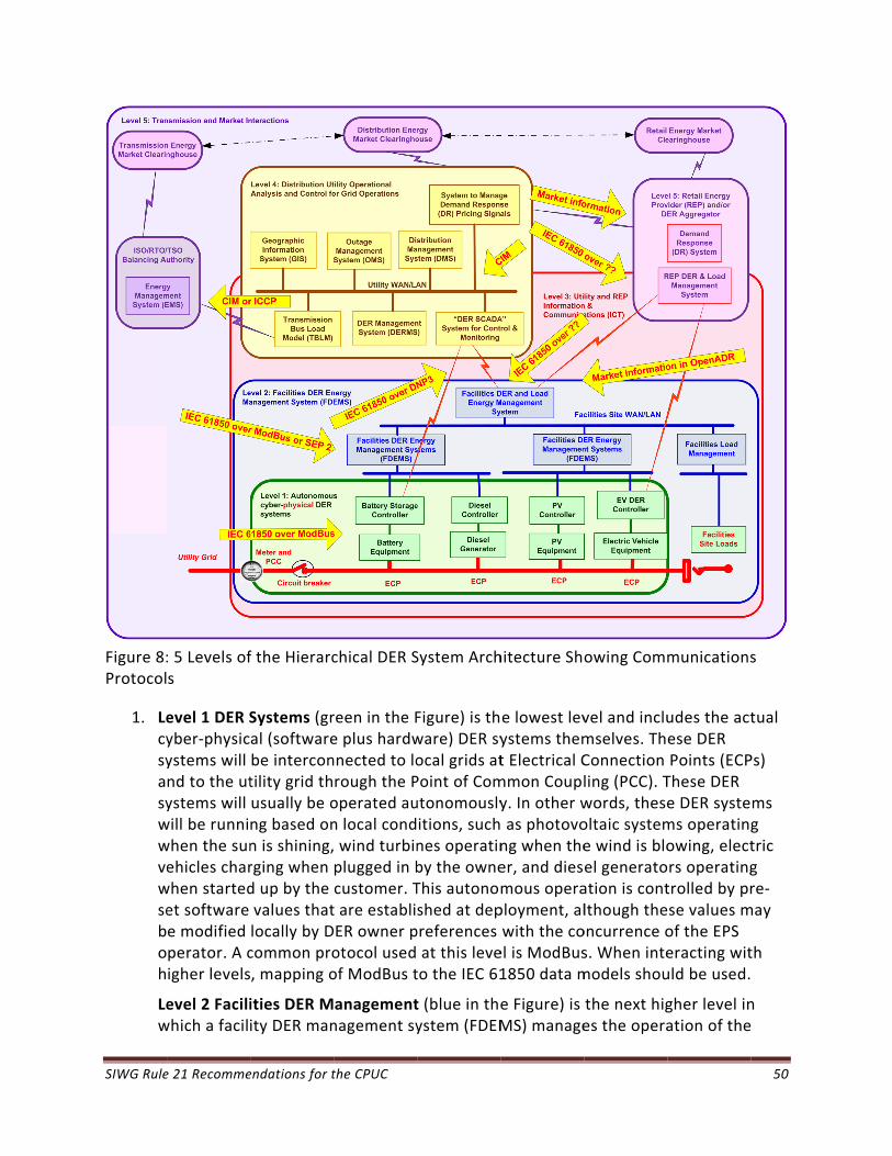
SIWG Rule
Figure 8:Protocol
1. Lecysyasywwvewseboh
Lew
e 21 Recomme
: 5 Levels ofs
evel 1 DER Syber‐physicystems will nd to the utystems will will be runniwhen the sunehicles charwhen startedet software e modified perator. A cigher levels
evel 2 Faciliwhich a facili
endations for t
f the Hierarc
Systems (gral (softwarebe intercontility grid thusually be ong based onn is shining,rging when d up by the values thatlocally by Dcommon pro, mapping o
ities DER Mity DER man
the CPUC
chical DER S
reen in the Fe plus hardwnnected to lorough the Poperated aun local cond wind turbinplugged in bcustomer. Tt are establiER owner potocol usedof ModBus t
anagementnagement sy
System Arch
Figure) is thware) DER syocal grids atPoint of Comutonomouslyitions, suchnes operatinby the owneThis autonomshed at deppreferences at this leveto the IEC 61
t (blue in theystem (FDEM
hitecture Sh
e lowest levystems themt Electrical Cmmon Couply. In other w as photovong when theer, and diesmous operaployment, alwith the coel is ModBus1850 data m
e Figure) is MS) manage
owing Comm
vel and inclumselves. ThConnection ling (PCC). Twords, theseoltaic systeme wind is bloel generatoation is contlthough theoncurrence os. When intemodels shou
the next higes the opera
munications
udes the actese DER Points (ECPThese DER e DER systems operatingowing, electrs operatingtrolled by prse values mof the EPS eracting wituld be used.
gher level ination of the
50
s
tual
Ps)
ms g tric g re‐
may
th
n
SIWG Rule 21 Recommendations for the CPUC 51
Level 1 DER systems. For simple facilities, such as a residential home, the FDEMS may be combined with the DER controllers, basically providing communications capabilities to the Level 1 DER systems. If a separate system, the FDEMS may be managing one or two DER systems in a residential home (e.g. a PV system and an electric vehicle). Larger FDEMS will be managing multiple DER systems in commercial and industrial sites, such as university campuses and shopping malls. Utilities may also use a FDEMS to handle DER systems located at utility sites such as substations or power plant sites. Within facilities, a number of different protocols could be used such as SEP2, BACnet, or OPC/UA but again, the protocols should be mapped to the IEC 61850 data models.
Level 3 Information and Communications Technology (ICT) Infrastructure (red in the Figure) provided the information exchanges beyond the local site to allow utilities and market‐based aggregators and retail energy providers (REP) to request or even command DER systems (typically through a FDEMS) to take specific actions, such as turning on or off, setting or limiting output, providing ancillary services (e.g. volt/var control), and other grid management functions. REP/aggregator requests would likely be price‐based focused on greater power system efficiency, while utility commands would also include safety and reliability purposes. The combination of this level and level 2 may have varying scenarios, while still fundamentally providing the same services, including cyber security. Power system management interactions should be based on IEC 61850 with mapping to DNP3, SEP2, or XMPP, while financial interactions could use other data models and protocols, such as OpenADR.
Level 4 Distribution Utility Operational Analysis (yellow/brown in the Figure) applies to utility applications that are needed to determine what requests or commands should be issued to which DER systems. Utilities must monitor the power system and assess if efficiency or reliability of the power system can be improved by having DER systems modify their operation. This utility assessment involves many utility control center systems, including, but not limited to, Distribution Management Systems, Geographical Information Systems, Load Management Systems, Outage Management Systems, Demand Response systems, as well as DER database and management systems. Once the utility has determined that modified requests or commands should be issued, it will send these out as per Level 3. The interactions within the utility are expected to use the Common Information Model (CIM) (IEC 61968 and IEC 61970), MultiSpeak, or similar data models over “Internet XML‐based protocols” such as SOAP, XMPP, OPC/UA, etc.
Level 5 Transmission and Market Operations (purple in the Figure) is the highest level, and involves the larger utility environment where regional transmission operators (RTOs) or independent system operators (ISOs) may need information about DER capabilities or operations and/or may provide efficiency or reliability requests to the utility that is managing the DER systems within its domain. This may also involve the bulk power market systems, as well as market functions of retail energy providers.
SIWG Rule 21 Recommendations for the CPUC 52
3.4.2 Communications Alternatives
From the DER architecture diagram shown above, it is clear that a number of different communications technologies may be used in different environments and for different purposes. More than one type of communications media may be used across a network, different protocols may be involved, and different types of information exchanges may be needed. Cybersecurity needs to be “end‐to‐end” but different media and protocols use different cybersecurity methods, including different cipher suites, different key management approaches, and different network management methods.
IEC 61850‐7‐420 and IEC 61850‐90‐7 are standards that define the data models for most of the DER functions described in this document. They cover the “power system management” interactions that are required to manage the DER functions, while leaving the “financial” interactions that can include pricing signals to other data models, such as OpenADR. The IEC 61850 data models can be “mapped” to communication protocols, including ModBus, DNP3, SEP2, MMS, and others.
It is expected that utilities will primarily have “power system management” interactions with DER systems, or in many cases with the Facility DER Energy Management Systems (FDEMS). The FDEMS in turn will manage their DER systems using these same “power system management” data models. These “power system management” interactions will update settings, activate functions, monitor DER output, and issue commands to DER systems.
It is expected that Retail Energy Providers, Aggregators, and other Third Parties will primarily use “financial” interactions to trigger behavior changes of DER systems, although some may include “power system management” interactions depending upon contractual arrangements. The financial triggers will indicate to the FDEMS and their DER systems that the DER systems should use certain settings or initiate actions, but would not actually change any of the settings.
Two basic configurations can be used for translating between different protocols, namely translations within the utility environment and translations within the facility environment. In both cases, a “gateway” or other system provides this translation with two protocol stacks (see Figure 9). The utility and/or I‐DER owners could provide these translation gateways.

SIWG Rule 21 Recommendations for the CPUC 53
Figure 9: Communication layers, possible communications protocols choices, and an example of a communications gateway for translating protocols
3.5 Proposed Communications Requirements for Rule 21
The SIWG is presently defining a set of Phase 2 communications technologies based on standards that it will be able to present to the CPUC upon the acceptance of this phased approach. Therefore, the discussion of communication technologies here is for informational purposes.
In general, the SIWG is discussing communications requirements to be added to Rule 21 for the inverter component of DER systems. Ideas include the recommended practices in IEEE 1547.3 “Guide for Monitoring, Information Exchange, and Control of Distributed Resources Interconnected with Electric Power Systems”, and the IEC 61850 communications standard, with the understanding that these communications requirements will need to be adapted. The following communications technologies and capabilities are being discussed:
1. Provide capability for including and/or adding communications modules for different media interfaces.
2. Provide the TCP/IP internet protocols.
Utility DER-Related Applications
“Application” Protocol
Communications Layers
Data Model
DER Controller
Data Model
“Transport” Protocol
Communications Media
Utility private WANCellphone GPRSPublic InternetAMI NetworkRadio-based Network
“Application” Protocol
“Transport” Protocol
Communications Media
Internet Protocols:TCP/IP
DNP3 or XML
IEC 61850 Data Model
Possible Communication Choices
ModBus, SEP2, or XML
IEC 61850 Data Model
Internet Protocols:TCP/IP
SIWG Rule 21 Recommendations for the CPUC 54
3. Use the international standard IEC 61850 as the information model for defining the I‐DER data exchanges.
4. Support the mapping of the IEC 61850 information model to one or more communications protocols.
5. Provide cybersecurity at the transport and application layers.
6. Provide cybersecurity for user and device authentication.
3.6 Benefits of Communications with I-DER Systems
Although the Phase 1 I‐DER functions do not explicitly require communications, the full benefits of smart inverter functions can only be gained with the addition of communications. The primary benefits include:
Ability to update default or pre‐set parameters to meet changing power system requirements. For instance, if an I‐DER system is installed with specific parameter values, but 6 months later, either additional I‐DER systems are installed on the same circuit or the circuit itself is reconfigured, then those parameter values may need to be updated
Ability to monitor and control I‐DER systems so that the state of the power system can be better understood and managed by the utility.
Ability to upgrade smart inverter functions so that new understandings of how I‐DER systems interact with power system equipment or impact power system operations can be reflected in improved I‐DER functional capabilities. This capability is particularly important since many studies and analyses will need to take place on how best to integrate the smart I‐DER functions with existing utility equipment capabilities.
Ability to respond to safety and other emergencies through direct control actions on the I‐DER systems.
SIWG Rule 21 Recommendations for the CPUC 55
4. Defining the Potential Phase 3 Additional Advanced Inverter Functionalities
The SIWG has not yet considered the detailed requirements for the additional Advanced Smart Inverter Functionalities for the State of California. Internationally, advanced inverter standards are being considered and implemented.
4.1 Purpose of the Additional Advanced Inverter Functionalities
As the distribution system becomes more complex for utilities to manage with higher penetrations of I‐DER systems, additional I‐DER functions can provide significant benefits to safety, reliability, and efficiency of power system operations by providing utilities with increased visibility into the distribution system, additional control over these generation and storage capabilities, and more nuanced management of the power system. Utilities can take advantage of the communications provided in Phase 2 to interact directly or indirectly with large numbers of I‐DER systems.
These additional I‐DER functions will require additional discussion and refinement by the SIWG to develop consensus on key processes and parameters while still permitting the flexibility to modify details to meet specific utility requirements.
Currently Rule 21 does not presently address any advanced inverter functionalities.
4.2 Early Definition of Advanced Inverter Functionalities for Rule 21
Some of the advanced functionalities below identify the need for measurements at either the ECP or the PCC: it is expected that smaller I‐DER systems will most likely rely on measurements at their ECPs, while larger I‐DER systems may be required to use measurements at the PCC, depending upon specific interconnection requirements.
The SIWG has not begun formal discussions, but advanced inverter functionalities may consist of:
1. Provide emergency alarms and information: The I‐DER system (and aggregations of I‐DER systems, such as virtual power plants) provides alarms and supporting emergency information via the FDEMS to the utility. This function is feasible only if the ICT infrastructure is available.
2. Provide status and measurements on current energy and ancillary services: The I‐DER system (and aggregations of I‐DER systems, such as virtual power plants) provides current status, power system measurements, and other real‐time data (possibly aggregated via the FDEMS) to the utility, in order to support real‐time and short‐term analysis applications. This function is feasible only if the ICT infrastructure is available. (Revenue metering data is provided via alternate means.)
3. Limit maximum real power output at an ECP or the PCC upon a direct command from the utility: The utility issues a direct command to limit the maximum real power output at the ECP or PCC. The reason might be that unusual or emergency conditions are causing reverse flow into the feeder’s substation or because the total I‐DER real power

SIWG Rule 21 Recommendations for the CPUC 56
output on the feeder is greater than some percentage of total load. The command might be an absolute watt value or might be a percentage of I‐DER output. This function is feasible only if the ICT infrastructure is available. It might also be used to ensure fairness across many I‐DER systems.
4. Support direct command to disconnect or reconnect: The I‐DER system performs a disconnect or reconnect at the ECP or PCC. Time windows are established for different I‐DER systems to respond randomly within that window to the disconnect and reconnect commands. This function is feasible only if the ICT infrastructure is available.
5. Provide operational characteristics at initial interconnection and upon changes: The I‐DER system provides operational characteristics after its “discovery” and whenever changes are made to its operational status.
6. Test I‐DER software patching and updates: Initial I‐DER software installations and later updates are tested before deployment for functionality and for meeting regulatory and utility requirements, including safety. After deployment, testing validates the I‐DER systems are operating correctly, safely, and securely.
7. Counteract frequency excursions beyond normal limits by decreasing or increasing real power: The I‐DER system reduces real power to counteract frequency excursions beyond normal limits (and vice versa if additional generation or storage is available), particularly for microgrids. Hysteresis can be used as the frequency returns within the normal range to avoid abrupt changes by groups of I‐DER systems.
8. Counteract voltage excursions beyond normal limits by providing dynamic current support: The I‐DER system counteracts voltage anomalies (spikes or sags) through “dynamic current support”. The I‐DER system supports the grid during short periods of abnormally high or low voltage levels by feeding reactive current to the grid until the voltage either returns within its normal range, or the I‐DER system ramps down, or the I‐DER system is required to disconnect.
9. Limit maximum real power output at the ECP or PCC to a preset value: I‐DER systems are interconnected to the grid with a preset limit of real power output to be measured at the PCC. The reason might be that the I‐DER system is sized to handle most of the local load behind an ECP or the PCC, but occasionally that load decreases below a critical level and the increased real power at the ECP or PCC may cause backflow at the substation and be a reliability concern for the utility. This will be most effective for larger I‐DER systems or for large groups of smaller I‐DER systems.
10. Modify real power output autonomously in response to local voltage variations: The I‐DER system monitors the local (or feeder) voltage and modifies real power output in order to damp voltage deviations. Settings are coordinated between the utility and I‐DER operator. Hysteresis and delayed responses could be used to ensure overreactions or hunting do not occur.
11. Set actual real power output at the ECP or PCC: The utility either presets or issues a direct command to set the actual real power output at the ECP or PCC (constant export/import if load changes; constant watts if no load). The reason might be to establish a base or known generation level without the need for constant monitoring.

SIWG Rule 21 Recommendations for the CPUC 57
This is the approach often used today with synchronous generators. This function is feasible only if the ICT infrastructure is available. Meter reads could provide 15‐minute energy by the end of the day could provide production information for operational planning.
12. Schedule actual or maximum real power output at specific times: The utility establishes (or pre‐establishes) a schedule (e.g. on‐peak & off‐peak) of actual or maximum real power output levels at the ECP or PCC, possibly combining generation, storage, and load management. The reason might be to minimize output during low load conditions while allowing or requiring higher output during peak load time periods.
13. Smooth minor frequency deviations by rapidly modifying real power output to these deviations: The I‐DER system modifies real power output rapidly to counter minor frequency deviations. The frequency‐watt settings define the percentage of real‐power output to modify for different degrees of frequency deviations on a second or even sub‐second basis.
14. Follow schedules for energy and ancillary service outputs: The I‐DER system receives and follows schedules for real power settings, reactive settings, limits, modes (such as autonomous volt/var, frequency‐watt), and other operational settings.
15. Set or schedule the storage of energy for later delivery, indicating time to start charging, charging rate and/or “charge‐by” time: For a I‐DER system that has storage capabilities, such as battery storage or a combined PV + storage system or a fleet of electric vehicles. Preset time‐of‐charge values can be established. Settings are coordinated between the utility and I‐DER operator. Different scenarios could include:
Low load conditions at night are causing some renewable energy to be wasted, so charging energy storage I‐DER systems at that time makes power system operations more efficient.
I‐DER controller charges at the specified rate (less than or equal to the maximum charging rate) until the state‐of‐charge (SOC) reaches a specified level.
I‐DER controller charges at the necessary rate in order to reach the specified SOC within the “charge‐by” time.
4.3 Benefits of the Additional Advanced Inverter Functionalities
The many additional advanced I‐DER functions will increase utility visibility and control over the grid, improve grid stability, respond to utility emergencies, provide very fast counteractions to voltage and frequency fluctuations, improve power quality, and increase grid efficiency.
Each of the additional I‐DER functions will provide benefits for different situations as higher penetrations of I‐DER and other DER systems increasingly impact traditional distribution operations. These additional I‐DER functions will be further identified and discussed by the SIWG during the development of their detailed requirements during Phase 3.

SIWG Rule 21 Recommendations for the CPUC 58
5. Proposed Test Plan for Smart I-DER Systems
5.1.1 Scope and Purpose
The SIWG proposes a phased Test Plan for testing and validating I‐DER systems that include the smart I‐DER functions (smart I‐DER systems). All I‐DER systems that can support these smart I‐DER functions must be tested before they will be permitted to interconnect to the utility power systems.
The purpose of this testing is to ensure that these I‐DER systems do not compromise the safety and reliability of the utility’s power system, as well as that they meet the smart I‐DER functional requirements as identified in Rule 21.
5.1.2 Types of Tests
The following types of tests are necessary for ensuring the safety and reliability of the grid:
Internal manufacturer product testing: Manufacturer factory software tests for product functionality, performance, and basic communications before the products are released for external product testing. This testing is expected to be performed but is out‐of‐scope for this test plan document.
External manufacturer product testing: External product testing provides an independent assessment of product capabilities and conformance to specifications. Successful testing could lead to certification of the products. This testing could be done by NREL, SunSpec Alliance, TÜV Rhineland, DOE SunShot, Sandia, or other testing facility. Combinations of these testing facilities could be used, depending upon the purposes of the testing, funding levels, etc.
UL 1741 safety testing: Utilities will need to work with UL to develop two utility‐specific amendments to UL 1741 for certification (termed "Special Purpose Utility Interactive" Inverter Test). The first amendment should cover the safety requirements for the Phase 1 functions, while the second amendment should cover the safety requirements for the remaining Phase 2 and the Phase 3 functions.
Utility product functional and safety testing: Utilities may specify both general and utility‐specific requirements. Either the utility will participate in factory acceptance tests at the manufacturer’s site, or will bench test example products, and/or will require utility‐specific certification from the external testing processes, including UL 1741 certification, to ensure products meet these utility‐specific requirements.
Commissioning and site acceptance testing: Testing of I‐DER systems once commissioned covers the proper operation in the field. These tests may include Information and Communications Technology (ICT) testing, and on‐going I‐DER interconnection testing and experimenting with different settings for the functions.

SIWG Rule 21 Recommendations for the CPUC 59
Periodic interconnection tests: Periodic testing of the I‐DER functions should be used to verify continued compliance with the requirements, particularly if changes have been made to the I‐DER system, if nearby EPS configurations have been modified, or if significantly more I‐DER generation and storage have been added in electrically neighboring locations.
Product interoperability testing: Interoperability testing may be undertaken later when the complete suite ICT is specified and many products have implemented the smart I‐DER functions.
5.1.3 Sources of Testing Requirements
Tests should cover all mandatory and recommended I‐DER functions that are specified in Rule 21, including any mandatory information and communications technologies (ICT).
IEEE 1547.1 should be used as a source for updating California testing requirements for the specified I‐DER interconnections, but cannot wait for 1547.1a. However, coordination with that update process will be critical.
UL 1741 should be used as source for safety testing certification. Therefore, it is expected that California utilities will work with UL to update these safety certification requirements to cover the specified functions, using the UL utility‐specific amendment process. The Sandia National Laboratory has developed draft test procedures for the I‐DER functions which can be used by the UL testing group to develop the functional testing requirements and their safety criteria. Testing of I‐DER systems can then take place at any of the nationally recognized testing laboratories (NRTLs) which can issue UL certificates in addition to the functional test results.
Testing requirements for the ICT capabilities need to be defined, preferably using available testing procedures for transport layer communications (layers 1‐4/5), DNP3 testing, IEC 61850‐to‐DNP3 mapping tests, and other IEC 61850‐xx mappings. The Sandia National Laboratory draft test plans for the IEC 61850‐7‐420/90‐7 I‐DER functions and mappings can also be used as a source for these testing procedures.
5.2 Implementation Procedures
5.2.1 UL Certification for Pilot and for Commercial I-DER Systems
The pilot or experimental I‐DER systems that are sponsored by California utilities should undergo functional testing of the smart inverter functions, but do not necessarily require UL certification. Since the updating of the UL 1741 certification testing requirements may need many months, the functional testing of pilot I‐DER systems could be permitted to take place before the UL certification testing requirements are finalized.

SIWG Rule 21 Recommendations for the CPUC 60
Nonetheless, UL 1741 certification provides manufacturers with assurance that their product testing will meet the ultimate goal of certification for commercial I‐DER systems and avoids the need to undertake multiple testing procedures.
Therefore, it is recommended that, in conjunction with the SIWG, UL sponsor the development of the detailed functional testing procedures using the default settings and ranges, so that any certification issues can be handled within that process. Products could then be provided with UL certification after being tested at NRTLs.
5.2.2 Permissive Implementation Schedules
The functional testing and implementation of I‐DER systems should be based on a permissive schedule. In such a permissive schedule, certain milestones would have to be passed, but the next steps could then take place as rapidly or as slowly as the stakeholders agree to, up until the next milestone requirement. These milestones could have expected fixed dates or could result from joint agreements of stakeholders.
The milestones envisioned for permissive implementation schedules include:
Development of California‐specific Smart Inverter Functional Testing Procedures for each of the Test groups (Phase 1 functional tests, Phase 2 communication tests, and Phase 3 functional and communication tests), including testing assumptions, testing parameters, and testing compliance pass/fail criteria.
Utility permission to start deployment and site testing of pilot I‐DER systems that have passed the appropriate Smart Inverter Functional Tests.
Development of the California‐specific UL 1741 certification document and testing.
Utility permission to start deployment and site testing of commercially‐owned I‐DER systems that have passed the appropriate Smart Inverter Functional Tests and are UL 1741 certified.
Deadline for all new I‐DER implementations to comply with both Smart Inverter Functional Tests and UL 1741 certification.
5.2.3 Staggered Test groups
Although ultimately all I‐DER functions required by Rule 21 must be conformance tested for all sizes of I‐DER systems, this testing can be grouped and staggered over time to permit implementations to move ahead more rapidly in pilot projects and experimental systems. With this staggered testing approach the more critical Phase 1 functions can be implemented and tested first in the larger I‐DER installations, with the remaining functions and I‐DER sizes tested soon afterwards.
Therefore, four (4) test groups are defined (see Figure 10):
Test group A: Phase 1 autonomous functions for larger individual I‐DER systems > 10kW

SIWG Rule 21 Recommendations for the CPUC 61
Test group B: Phase 1 autonomous functions for smaller individual I‐DER systems < 10 kW
Test group C: Phase 2 communications capabilities
Test group D: Phase 3 additional functions in all I‐DER systems
Figure 10: Staggered Test groups
Test plans for optional I‐DER functions are not covered at this time.
5.3 Schedules for Permissive Implementations of Staggered Testing of Smart I-DER Functions
Utilities require the conformance testing of I‐DER systems according to Rule 21 before these I‐DER systems are interconnected to their power systems.
The testing and deployment of these I‐DER systems involve a number of tasks by manufacturers and implementers. Some of these testing tasks may be performed in parallel and/or staggered over time, but all must eventually be undertaken and successfully passed.
The initial tasks are common to all Test groups, and cover the publishing, review, and comment resolution of the smart I‐DER functions and the test plan. The tasks for the different Test groups are covered in separate schedules.
Since subsequent dates in the timeframe may be affected by the completion of tasks on previous dates, both the dates that are the goals for each task and the delta months between tasks are shown in the Tables. If major discrepancies between the goal date and

SIWG Rule 21 Recommendations for the CPUC 62
the delta months occur during these test groups, the goal dates will be reviewed. The final milestone date is the most important, so even if intermediate goal dates are not met, the final milestone date for each Group must be achieved.
The dates in the testing tables below are defined as follows:
Milestones are dates by which the required actions should take place.
Permissive dates are the start time that actions may begin to take place but are not required to take place.
Other dates are expected or desired dates for actions to take place but are not binding.
A Gantt chart is provided to capture the key scheduling tasks and milestones.
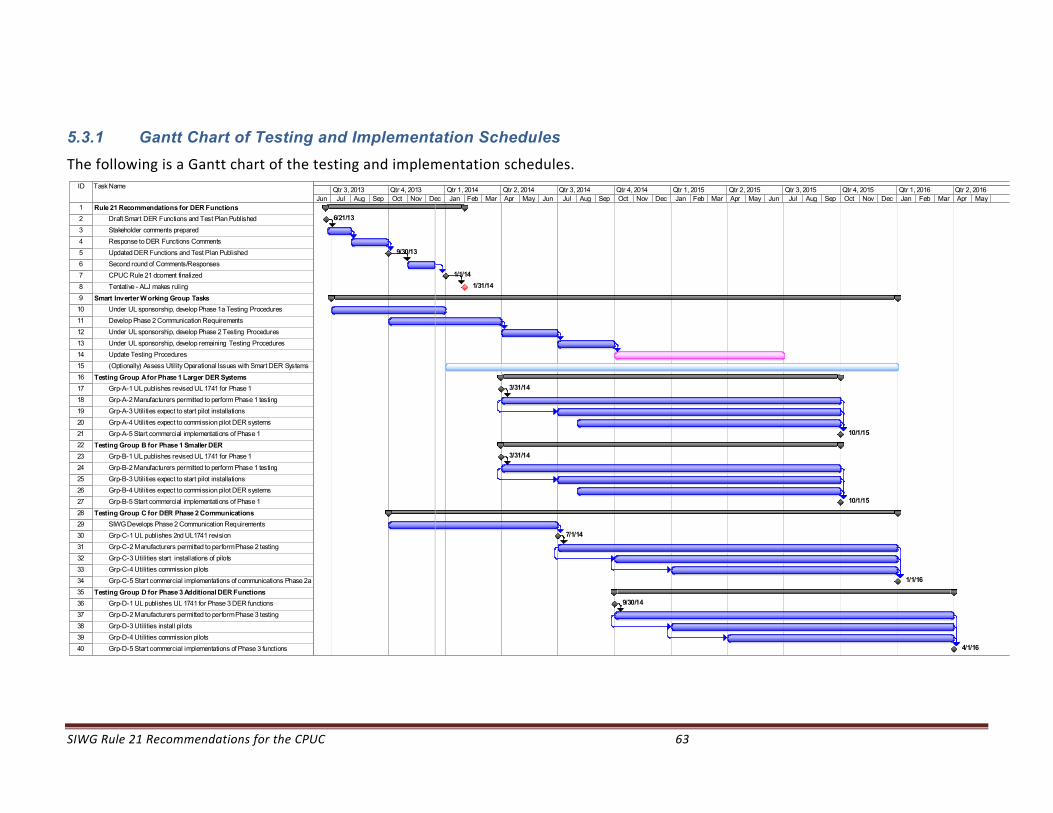
SIWG Rule 21 Recommendations for the CPUC 63
5.3.1 Gantt Chart of Testing and Implementation Schedules
The following is a Gantt chart of the testing and implementation schedules.
ID Task Name
1 Rule 21 Recommendations for DER Functions
2 Draft Smart DER Functions and Test Plan Published
3 Stakeholder comments prepared
4 Response to DER Functions Comments
5 Updated DER Functions and Test Plan Published
6 Second round of Comments/Responses
7 CPUC Rule 21 dcoment finalized
8 Tentative - ALJ makes ruling
9 Smart Inverter W orking Group Tasks
10 Under UL sponsorship, develop Phase 1a Testing Procedures
11 Develop Phase 2 Communication Requirements
12 Under UL sponsorship, develop Phase 2 Testing Procedures
13 Under UL sponsorship, develop remaining Testing Procedures
14 Update Testing Procedures
15 (Optionally) Assess Utility Operational Issues with Smart DER Systems
16 Testing Group A for Phase 1 Larger DER Systems
17 Grp-A-1 UL publishes revised UL 1741 for Phase 1
18 Grp-A-2 Manufacturers permitted to perform Phase 1 testing
19 Grp-A-3 Utilities expect to start pilot installations
20 Grp-A-4 Utilities expect to commission pilot DER systems
21 Grp-A-5 Start commercial implementations of Phase 1
22 Testing Group B for Phase 1 Smaller DER
23 Grp-B-1 UL publishes revised UL 1741 for Phase 1
24 Grp-B-2 Manufacturers permitted to perform Phase 1 testing
25 Grp-B-3 Utilities expect to start pilot installations
26 Grp-B-4 Utilities expect to commission pilot DER systems
27 Grp-B-5 Start commercial implementations of Phase 1
28 Testing Group C for DER Phase 2 Communications
29 SIWG Develops Phase 2 Communication Requirements
30 Grp-C-1 UL publishes 2nd UL1741 revision
31 Grp-C-2 Manufacturers permitted to perform Phase 2 testing
32 Grp-C-3 Utilities start installations of pilots
33 Grp-C-4 Utilities commission pilots
34 Grp-C-5 Start commercial implementations of communications Phase 2a
35 Testing Group D for Phase 3 Additional DER Functions
36 Grp-D-1 UL publishes UL 1741 for Phase 3 DER functions
37 Grp-D-2 Manufacturers permitted to perform Phase 3 testing
38 Grp-D-3 Utilities install pilots
39 Grp-D-4 Utilities commission pilots
40 Grp-D-5 Start commercial implementations of Phase 3 functions
6/21/13
9/30/13
1/1/14
1/31/14
3/31/14
10/1/15
3/31/14
10/1/15
7/1/14
1/1/16
9/30/14
4/1/16
Jun Jul Aug Sep Oct Nov Dec Jan Feb Mar Apr May Jun Jul Aug Sep Oct Nov Dec Jan Feb Mar Apr May Jun Jul Aug Sep Oct Nov Dec Jan Feb Mar Apr MayQtr 3, 2013 Qtr 4, 2013 Qtr 1, 2014 Qtr 2, 2014 Qtr 3, 2014 Qtr 4, 2014 Qtr 1, 2015 Qtr 2, 2015 Qtr 3, 2015 Qtr 4, 2015 Qtr 1, 2016 Qtr 2, 2016
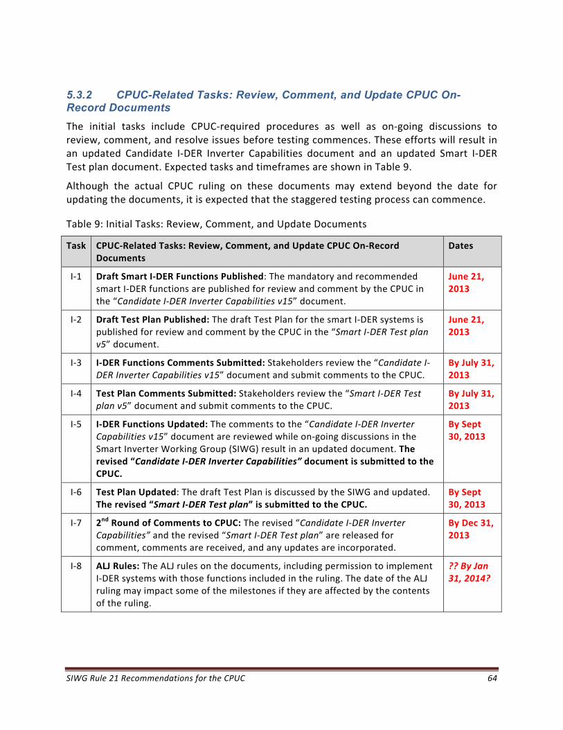
SIWG Rule 21 Recommendations for the CPUC 64
5.3.2 CPUC-Related Tasks: Review, Comment, and Update CPUC On-Record Documents
The initial tasks include CPUC‐required procedures as well as on‐going discussions to review, comment, and resolve issues before testing commences. These efforts will result in an updated Candidate I‐DER Inverter Capabilities document and an updated Smart I‐DER Test plan document. Expected tasks and timeframes are shown in Table 9.
Although the actual CPUC ruling on these documents may extend beyond the date for updating the documents, it is expected that the staggered testing process can commence.
Table 9: Initial Tasks: Review, Comment, and Update Documents
Task CPUC‐Related Tasks: Review, Comment, and Update CPUC On‐Record Documents
Dates
I‐1 Draft Smart I‐DER Functions Published: The mandatory and recommended smart I‐DER functions are published for review and comment by the CPUC in the “Candidate I‐DER Inverter Capabilities v15” document.
June 21, 2013
I‐2 Draft Test Plan Published: The draft Test Plan for the smart I‐DER systems is published for review and comment by the CPUC in the “Smart I‐DER Test plan v5” document.
June 21, 2013
I‐3 I‐DER Functions Comments Submitted: Stakeholders review the “Candidate I‐DER Inverter Capabilities v15” document and submit comments to the CPUC.
By July 31, 2013
I‐4 Test Plan Comments Submitted: Stakeholders review the “Smart I‐DER Test plan v5” document and submit comments to the CPUC.
By July 31, 2013
I‐5 I‐DER Functions Updated: The comments to the “Candidate I‐DER Inverter Capabilities v15” document are reviewed while on‐going discussions in the Smart Inverter Working Group (SIWG) result in an updated document. The revised “Candidate I‐DER Inverter Capabilities” document is submitted to the CPUC.
By Sept 30, 2013
I‐6 Test Plan Updated: The draft Test Plan is discussed by the SIWG and updated. The revised “Smart I‐DER Test plan” is submitted to the CPUC.
By Sept 30, 2013
I‐7 2nd Round of Comments to CPUC: The revised “Candidate I‐DER Inverter Capabilities” and the revised “Smart I‐DER Test plan” are released for comment, comments are received, and any updates are incorporated.
By Dec 31, 2013
I‐8 ALJ Rules: The ALJ rules on the documents, including permission to implement I‐DER systems with those functions included in the ruling. The date of the ALJ ruling may impact some of the milestones if they are affected by the contents of the ruling.
?? By Jan 31, 2014?

SIWG Rule 21 Recommendations for the CPUC 65
5.3.3 Upcoming Smart Inverter Working Group (SIWG) Tasks
The Smart Inverter Working Group (SIWG) is expected to continue to work together to address tasks related to defining functional and communication requirements as well as the testing procedures for meeting those requirements. These tasks are shown in Table 10.
Table 10: Smart Inverter Working Group Tasks
Task SIWG Tasks: Develop Smart Inverter Testing Procedures Milestones
SIWG‐1 Under UL sponsorship, develop Phase 1 Testing Procedures: Working under the sponsorship of UL and coordinating with the IEEE 1547.1a effort, the SIWG defines the testing procedures, the testing assumptions, the testing parameters for each of the I‐DER functions, and the pass/fail criteria for each type of test for Phase 1 functions. These detailed Testing Procedures will become a part of ANSI/UL 1741 to be used to certify the Phase 1 I‐DER functions.
By Mar 31, 2014
SIWG‐2 Develop Phase 2 Communication Requirements: Working with communication experts and other stakeholders, the SIWG defines the communication and cyber security requirements for I‐DER systems interconnected to California power systems.
By Mar 31, 2014
SIWG‐3 Under UL sponsorship, develop Phase 2 Communication Testing Procedures: Working under the sponsorship of UL and including communication experts and other stakeholders, the SIWG defines the testing procedures, the testing assumptions, the testing parameters for communications and cyber security, and the pass/fail criteria for each type of test for Phase 2 capabilities.
By June 30, 2014
SIWG‐4 Under UL sponsorship, develop Remaining Testing Procedures: Working under the sponsorship of UL and coordinating with the IEEE 1547.1a group and other stakeholders, the SIWG defines the testing procedures, the testing assumptions, the testing parameters for each of the I‐DER functions, and the pass/fail criteria for each type of test for the remaining Phase 1 and 2 I‐DER functions.
By June 30, 2014
SIWG‐5 Update Testing Procedures: As needed, the SIWG will update the testing procedures, coordinating with the test groups and the standards groups with the goal of interoperability.
By Mar 31, 2015
SIWG‐6 (Optionally) Assess Utility Operational Issues with Smart I‐DER Systems: Since these smart I‐DER systems will impact utility operational procedures, the SIWG could optionally study these impacts on California utility operations in conjunction with IEEE 1547 groups and other stakeholders.
Open

SIWG Rule 21 Recommendations for the CPUC 66
5.3.4 Test group A – Phase 1 Autonomous Functions for Larger I-DER Systems
Test group A covers the testing of Phase 1 autonomous functions for larger I‐DER systems that are greater than 10 kW as individual units. Some of the tasks are milestones with dates that will affect subsequent tasks. Some tasks are permissive or expectations of when certain activities may commence, but are not binding. The schedule of tasks is shown in Table 11.
Table 11: Test group A – Phase 1 Autonomous Functions for Larger I‐DER Systems
Tasks Test group A – Phase 1 Autonomous Functions for Larger I‐DER Systems
Schedule Goals
Delta Months
Grp‐A‐1
Milestone
UL Publishes the Revised ANSI/UL 1741: UL publishes the first revision of ANSI/UL 1741 with testing procedures for the autonomous Phase 1 functions for Group A.
By March 31, 2014
Group A Testing Start (Start Grp‐A)
Grp‐A‐2 Start Functional Testing and Certification: Manufacturers are permitted to start the initial external manufacturing product testing and certification of their I‐DER systems using the default settings and covering the complete range of adjustment for Phase 1 I‐DER functions.
April 1, 2014
Permissive immediately after Milestone
Grp‐A‐3 Start Pilot Installations: Manufacturers and utilities commence the installation of tested and certified I‐DER systems in pilot or experimental settings.
July 1, 2014 3 months from Start Grp‐A
Grp‐A‐4 Commission Pilot Implementations: Manufacturers and utilities commence the commissioning of the pilot I‐DER systems after any required site acceptance testing.
August 1, 2014
4 months from Start Grp‐A
Grp‐A‐5
Milestone
Start Commercial Implementations of I‐DER Systems:
Start commercial implementations of Phase 1 I‐DER systems: all new implementations of I‐DER systems include the Phase 1 functions.
Oct 1, 2015 18 months from Start Grp‐A
5.3.5 Test group B – Phase 1 Autonomous Functions for Smaller I-DER Systems
Test group B covers the testing of the Phase 1 autonomous functions for smaller I‐DER systems that are less than 10 kW. The schedule of tasks is shown in Table 12.

SIWG Rule 21 Recommendations for the CPUC 67
Table 12: Test group B – Phase 1 Autonomous Functions for Smaller I‐DER Systems
Tasks Group B – Phase 1 Autonomous Functions for Smaller DERs < 10kW
Schedule Goals
Delta Months
Grp‐B‐1
Milestone
UL Publishes the Revised ANSI/UL 1741: UL publishes the first revision of ANSI/UL 1741 with testing procedures for the autonomous Phase 1 functions for Group B.
By March 31, 2014
Group A Testing Start (Start Grp‐B)
Grp‐B‐2 Start Functional Testing and Certification: Manufacturers are permitted to start the initial external manufacturing product testing and certification of their I‐DER systems using the default settings and covering the complete range of adjustment for Phase 1 I‐DER functions.
April 1, 2014
Permissive immediately after Milestone
Grp‐B‐3 Start Pilot Installations: Manufacturers and utilities commence the installation of tested and certified I‐DER systems in pilot or experimental settings.
July 1, 2014 3 months from Start Grp‐B
Grp‐B‐4 Commission Pilot Implementations: Manufacturers and utilities commence the commissioning of the pilot I‐DER systems after any required site acceptance testing.
August 1, 2014
4 months from Start Grp‐B
Grp‐B‐5
Milestone
Start Commercial Implementations of I‐DER Systems: All new commercial implementations of I‐DER systems must meet the Rule 21 Phase 1 requirements.
Oct 1, 2015 18 months from Start Grp‐B
5.3.6 Test group C – Phase 2 Communications Capabilities for I-DER Systems
Test group C covers the testing of Phase 2 communications for I‐DER systems. This testing covers only the actual communications capabilities, and does not necessarily cover any I‐DER functions that might use the communications. However, some I‐DER functions could be identified as part of default methods for testing the communications. The schedule of tasks is shown in Table 13.

SIWG Rule 21 Recommendations for the CPUC 68
Table 13: Test group C – Phase 2 Communications Capabilities for I‐DER Systems
Tasks Group C – Phase 2 Communications Capabilities for I‐DER Systems
Schedule Goals
Delta Months
Grp‐C‐1
Milestone
UL Publishes the Second Revision of ANSI/UL 1741: UL publishes the second revision of ANSI/UL 1741, covering the Phase 2 testing procedures for I‐DER systems with communications, including the default settings and conditions to be used in testing communications for Group C.
By June 30, 2014
Group C Testing Start (Start Grp‐C)
Grp‐C‐2 Start Functional Testing and Certification: Manufacturers are permitted to start the initial external manufacturing product testing and certification of I‐DER systems with communications including protocol converters and security. UL 1741 testing will be based on the second California‐specific amendment.
July 1, 2014 Permissive immediately after Milestone
Grp‐C‐3 Start Pilot Installations: Manufacturers and utilities commence the installation of tested and certified I‐DER systems with communications in pilot or experimental settings including protocol converters and security.
Oct 1, 2014 3 months from Start Grp‐C
Grp‐C‐4 Commission Pilot Implementations: Manufacturers and utilities commence the commissioning of the pilot I‐DER systems with communications after any required site acceptance testing including protocol converters and security.
Jan 1, 2015 6 months from Start Grp‐C
Grp‐C‐5
Milestone Start Commercial Implementations of I‐DER Systems
Start commercial Implementations of Phase 2 communications for I‐DER systems: all new implementations of I‐DER systems include the Phase 2 communication capabilities.
Jan 1, 2016 18 months from Start Grp‐C
5.3.7 Test group D – Phase 3 Additional I-DER Functions
Test group E covers the testing of the Phase 3 additional I‐DER functions which require communications capabilities, including the updating of settings for the autonomous I‐DER functions in Phase 1. It also covers the testing of the Phase 3 autonomous functions for all I‐DER systems. The schedule of tasks is shown in Table 14.
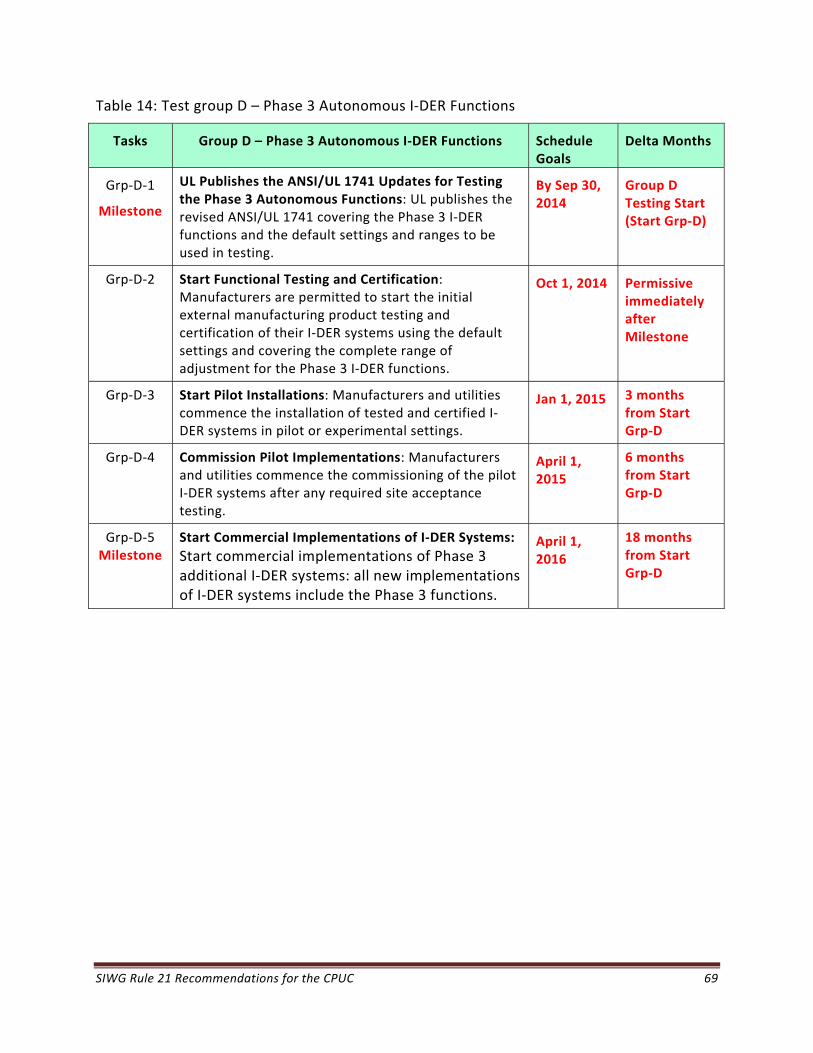
SIWG Rule 21 Recommendations for the CPUC 69
Table 14: Test group D – Phase 3 Autonomous I‐DER Functions
Tasks Group D – Phase 3 Autonomous I‐DER Functions Schedule Goals
Delta Months
Grp‐D‐1
Milestone
UL Publishes the ANSI/UL 1741 Updates for Testing the Phase 3 Autonomous Functions: UL publishes the revised ANSI/UL 1741 covering the Phase 3 I‐DER functions and the default settings and ranges to be used in testing.
By Sep 30, 2014
Group D Testing Start (Start Grp‐D)
Grp‐D‐2 Start Functional Testing and Certification: Manufacturers are permitted to start the initial external manufacturing product testing and certification of their I‐DER systems using the default settings and covering the complete range of adjustment for the Phase 3 I‐DER functions.
Oct 1, 2014 Permissive immediately after Milestone
Grp‐D‐3 Start Pilot Installations: Manufacturers and utilities commence the installation of tested and certified I‐DER systems in pilot or experimental settings.
Jan 1, 2015 3 months from Start Grp‐D
Grp‐D‐4 Commission Pilot Implementations: Manufacturers and utilities commence the commissioning of the pilot I‐DER systems after any required site acceptance testing.
April 1, 2015
6 months from Start Grp‐D
Grp‐D‐5 Milestone
Start Commercial Implementations of I‐DER Systems:
Start commercial implementations of Phase 3 additional I‐DER systems: all new implementations of I‐DER systems include the Phase 3 functions.
April 1, 2016
18 months from Start Grp‐D
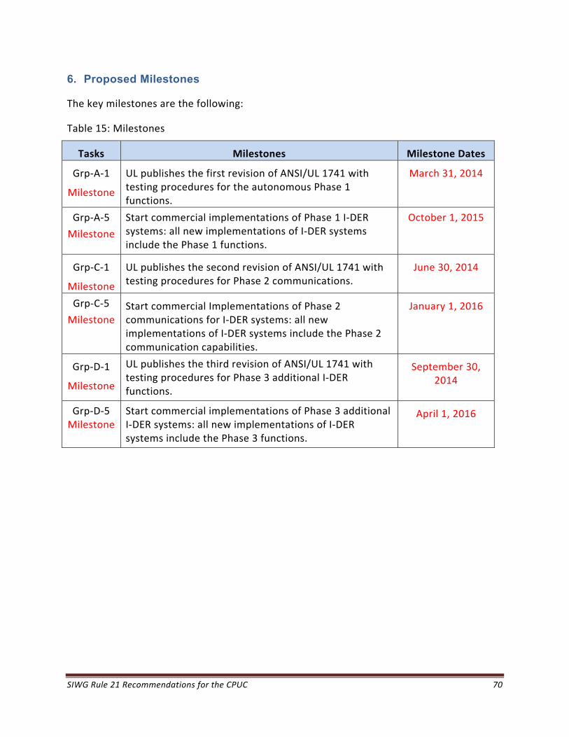
SIWG Rule 21 Recommendations for the CPUC 70
6. Proposed Milestones
The key milestones are the following:
Table 15: Milestones
Tasks Milestones Milestone Dates
Grp‐A‐1
Milestone
UL publishes the first revision of ANSI/UL 1741 with testing procedures for the autonomous Phase 1 functions.
March 31, 2014
Grp‐A‐5
Milestone
Start commercial implementations of Phase 1 I‐DER systems: all new implementations of I‐DER systems include the Phase 1 functions.
October 1, 2015
Grp‐C‐1
Milestone
UL publishes the second revision of ANSI/UL 1741 with testing procedures for Phase 2 communications.
June 30, 2014
Grp‐C‐5
Milestone Start commercial Implementations of Phase 2 communications for I‐DER systems: all new implementations of I‐DER systems include the Phase 2 communication capabilities.
January 1, 2016
Grp‐D‐1
Milestone
UL publishes the third revision of ANSI/UL 1741 with testing procedures for Phase 3 additional I‐DER functions.
September 30, 2014
Grp‐D‐5 Milestone
Start commercial implementations of Phase 3 additional I‐DER systems: all new implementations of I‐DER systems include the Phase 3 functions.
April 1, 2016
SIWG Rule 21 Recommendations for the CPUC 71
7. Conclusion
As California approaches greater numbers of installed DER systems and higher penetrations on certain circuits, enabling the use of smart inverter functionalities will assist with the transition to smarter distribution grid operation that optimizes the distributed generation and storage capabilities of interconnected resources.
The diverse stakeholders of the SIWG recommend the approach set out in this document as the path forward to that optimization.

SIWG Rule 21 Recommendations for the CPUC 72
A. Appendix A: Chart of Mandatory, Recommended, Optional I-DER Functions
The following 5 charts assemble all of the I‐DER functionalities discussed in this document.
Phase 1 includes all the mandatory basic autonomous I‐DER functionalities.
Phase 2 includes the mandatory requirements for information and communications technologies (ICT) for communications with I‐DER systems.
Phase 3 includes the additional advanced recommended I‐DER functionalities.
The I‐DER Functions column provides a brief description of the function.
The Description column provides additional information on the purpose and likely use of the function. This information is strictly technical; it does not address financial, regulatory, or legal issues. I‐DER systems will only be expected to meet the requirements within their capabilities. Minimum capabilities will need to be established for specific situations.
The Communications Requirements column indicates whether the function is essentially autonomous (not requiring communications), or local (requiring some local communications such as monitoring voltage), or ICT (requiring ICT facilities with the utility or other entity for direct commands, updating settings, establishing schedules, and other information exchanges).
The M/R/O column indicates whether the I‐DER function should be identified as mandated (M) or recommended (R) in Rule 21. Mandated functions must be able to operate at least autonomously, although some functions may also require ICT capabilities. If a function is mandated, all new I‐DER systems would be required to provide that function or capability, although the function may not be activated initially.
The Constraints and Comments column indicates what constraints there should be on the Rule 21 requirements. These include constraints on I‐DER size, type of I‐DER, location of I‐DER, etc.
– No specific value has yet been determined to identify a “larger” I‐DER system, and this size may vary depending upon the “electrical” environment of the I‐DER, including location relative to the substation, the capabilities of neighboring I‐DER systems, and the resilience of the grid to perturbations.
– The additional (E) indicates mandated in some European countries.
A.1 Phase 1: Key Autonomous I-DER Functions
It is recommended that the Phase 1 key autonomous I‐DER functions shown in Table 16 should be required (M in the Table) in Rule 21 such that utilities may specify them for new implementations of inverter‐based I‐DER systems in California, even though these functions

SIWG Rule 21 Recommendations for the CPUC 73
may not necessarily be immediately activated. Most, but not all, of the Phase 1 functions are described in IEC 61850‐90‐7, with extracts provided in the document “Advanced Functions for I‐DER Inverters Modeled in IEC 61850‐90‐7.pdf”.24
Table 16: Phase 1 Basic Autonomous I‐DER functions
Phase 1 I‐DER Functions
Description Communication Requirements
M/R Constraints & Comments
Anti‐Islanding: Support anti‐islanding to trip off under extended anomalous conditions
The I‐DER system trips off if voltage or frequency limits are exceeded over specified time periods.
Although default trip‐off limits settings would be implemented initially, these settings could be modifiable through agreement between the Area EPS and the I‐DER operator.
Autonomous
Local: Monitor voltage
Local: Monitor frequency
M All I‐DER systems
(E)
LHVRT: Provide ride‐through of low/high voltage excursions beyond normal limits
The I‐DER system remains connected during voltage excursions beyond normal limits, based on extended voltage limits during specified time windows. The I‐DER system would disconnect only when the ride‐through window has expired.
Although default ride‐through settings would be implemented initially, these settings could be modifiable through agreement between the Area EPS and the I‐DER operator, based on the technical capabilities of the I‐DER system and used to possibly mitigate abrupt losses of generation.
Autonomous
Local: Monitor voltage
M All I‐DER systems
(E)
24 Available at http://collaborate.nist.gov/twiki‐sggrid/pub/SmartGrid/PAP07Storage/Advanced_Functions_for_DER_Inverters_Modeled_in_IEC_61850‐90‐7.pdf

SIWG Rule 21 Recommendations for the CPUC 74
Phase 1 I‐DER Functions
Description Communication Requirements
M/R Constraints & Comments
LHFRT: Provide ride‐through of low/high frequency excursions beyond normal limits
The I‐DER system remains connected during frequency excursions beyond normal limits, based on extended frequency limits during specified time windows. The I‐DER system would disconnect only when the ride‐through window has expired.
Although default ride‐through settings would be implemented initially, these settings could be modifiable through agreement between the Area EPS and the I‐DER operator, based on the technical capabilities of the I‐DER system and used to possibly mitigate abrupt losses of generation.
Autonomous
Local: Monitor frequency
M All I‐DER systems
(E)
Volt‐Var Control: Provide volt/var control through dynamic reactive power injection through autonomous responses to local voltage measurements
The I‐DER system implements volt/var curves that define the available reactive power required at different voltage levels. Settings are coordinated between the utility and I‐DER operator. Available reactive power is defined as what reactive power is available without decreasing real power output.
I‐DER controller contains pre‐established volt/var settings, and/or
Volt/var settings can be updated remotely
Autonomous
Local: Monitor voltage
ICT: Utility updates volt/var curves
M
All I‐DER systems but may not always be activated
(E)
Ramping: Define ramp rates
The default ramp rate is established, contingent upon what the I‐DER can do. Additional emergency ramp rates and high/low ramp rate limits may also be defined.
Autonomous
ICT: Utility modifies the ramp rate
M All I‐DER systems but may not always be activated
Fixed PF: Provide reactive power by a fixed power factor
The I‐DER system sets the inverter to the specified power factor setting:
I‐DER controller contains pre‐established power factor setting, and/or
Power factor setting can be updated remotely
Autonomous
ICT: Utility modifies the power factor
M
All I‐DER systems
(E)

SIWG Rule 21 Recommendations for the CPUC 75
Phase 1 I‐DER Functions
Description Communication Requirements
M/R Constraints & Comments
Soft‐Start Reconnection: Reconnect after grid power is restored
The I‐DER system reconnects to the grid after power is restored using soft‐start methods such as ramping up and/or randomly turning on within a time window after grid power is restored, to avoid abrupt increases in generation.. The delay time between power restoration and the start of reconnection is preset, as are the ramping rate and the time window.
Autonomous
Local: Monitor voltage
Local: Monitor frequency
M All I‐DER systems but may not always be activated
(E)
A.2 Phase 2: Communications Technologies for I-DER Functions
It is recommended that standards‐based communications technologies necessary for supporting information exchanges between utilities and I‐DER facilities and based on the requirements shown in Table 17, should be mandatory for use by all new implementations of I‐DER systems requiring communications in California. Details of these communication requirements are in a separate document. The compliance date may be later than for autonomous I‐DER functions.
Table 17: Standards‐based communications technologies requirements
Phase 2 I‐DER Communications
Description Communication Requirements
M/R/O
Constraints & Comments
Communication Interface: Provide capability for adding communication modules for media interfaces
Standard interfaces can connect to different wired and/or wireless media. These media could include utility wireless systems, cellphone GPRS, customer WiFi network, and the Internet.
Utilities would specify which communication interface modules are required for specific implementations.
ICT: Provide communications between the I‐DER system and the utility (possibly through the customer’s FDEMS)
M The ability to communicate is mandatory, but no specific media is mandated
Transport Protocols: Provide the TCP/IP internet protocols
Basic Internet transport layer standards of TCP/IP, in particular an IP address.
ICT: Use common transport layer protocols
M IP address is required. Possibly IPv6 address?
Data Model: Use the IEC 61850 information model for defining data exchanges
Abstract information models for I‐DER systems should use the IEC 61850‐7‐420 and IEC 61850‐90‐7 for I‐DER systems.
ICT: Use interoperable data models, even if mapped to different protocols
M Require international standards for information models

SIWG Rule 21 Recommendations for the CPUC 76
Phase 2 I‐DER Communications
Description Communication Requirements
M/R/O
Constraints & Comments
Mapping to Application Protocols: Support the mapping of the IEC 61850 information model to communication protocols
I‐DER systems should support the ability to map the abstract IEC 61850 information model to standard protocols, such as ModBus, DNP3 (IEEE 1815), IEC 61850 (MMS), SEP 2.0, etc.
The default protocol for communications with a utility is DNP3 (IEEE 1815:2012) although other mutually agreed to protocols could be used. The utility protocol may be used between a facility gateway and the utility, while the communications between the facility gateway and the I‐DER systems may use other protocols. This gateway may be provided by the I‐DER owner or by the utility, reflecting the most economical arrangement.
ICT: Permit different protocol mappings
M The ability to map from the IEC 61850 information model to protocols is required. DNP3 (IEEE 1815:2012) is expected to be used for communications with the utilities through a facility gateway, although other protocols may be mutually agreed to,
Transport Cyber Security: Provide cyber security at the transport layer
Cyber security at the transport layer should be provided, such as Transport Layer Security (TLS) or IEEE 802.11i.
ICT: Provide transport layer cybersecurity
M TLS provides easily implemented standard cybersecurity
User Cyber Security: Provide cyber security for user and device authentication
Cyber security for user and device identification and authentication should be provided, based on user passwords, device security certificates, and role‐based access control. Confidentiality is optional. Public Key Infrastructure (PKI) could be used for key management.25
ICT: Require user and device authentication
M All access to I‐DER systems should include authentication
A.3 Phase 3: I-DER Functions Requiring Communications
It is recommended that the Phase 3 I‐DER functions requiring communication shown in Table 18 should be required (M in the Table) or recommended (R in the Table) in Rule 21 such that utilities may specify them for new implementations of inverter‐based I‐DER systems, even though these functions may not necessarily be immediately activated.
25References to external documents on I‐DER cyber security include: ISA 99, NISTIR 7628, I‐DER cyber security in SGIP DRGS DEWG, and IEC 62351 series.
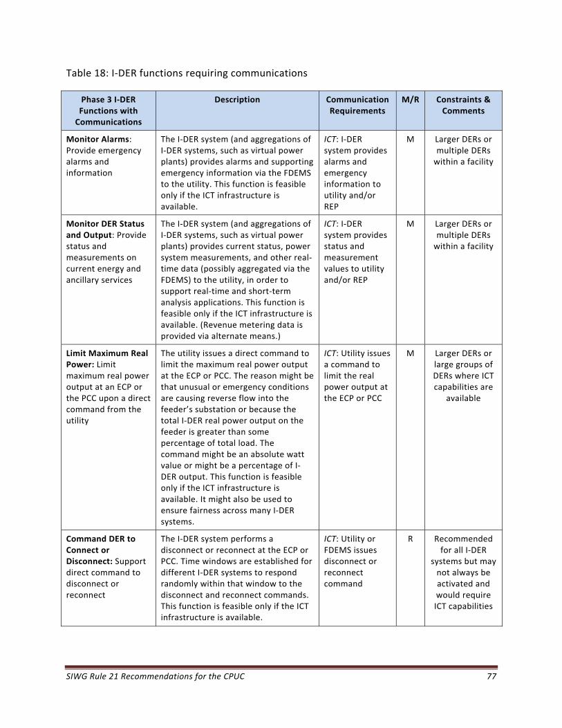
SIWG Rule 21 Recommendations for the CPUC 77
Table 18: I‐DER functions requiring communications
Phase 3 I‐DER Functions with Communications
Description Communication Requirements
M/R Constraints & Comments
Monitor Alarms: Provide emergency alarms and information
The I‐DER system (and aggregations of I‐DER systems, such as virtual power plants) provides alarms and supporting emergency information via the FDEMS to the utility. This function is feasible only if the ICT infrastructure is available.
ICT: I‐DER system provides alarms and emergency information to utility and/or REP
M Larger DERs or multiple DERs within a facility
Monitor DER Status and Output: Provide status and measurements on current energy and ancillary services
The I‐DER system (and aggregations of I‐DER systems, such as virtual power plants) provides current status, power system measurements, and other real‐time data (possibly aggregated via the FDEMS) to the utility, in order to support real‐time and short‐term analysis applications. This function is feasible only if the ICT infrastructure is available. (Revenue metering data is provided via alternate means.)
ICT: I‐DER system provides status and measurement values to utility and/or REP
M Larger DERs or multiple DERs within a facility
Limit Maximum Real Power: Limit maximum real power output at an ECP or the PCC upon a direct command from the utility
The utility issues a direct command to limit the maximum real power output at the ECP or PCC. The reason might be that unusual or emergency conditions are causing reverse flow into the feeder’s substation or because the total I‐DER real power output on the feeder is greater than some percentage of total load. The command might be an absolute watt value or might be a percentage of I‐DER output. This function is feasible only if the ICT infrastructure is available. It might also be used to ensure fairness across many I‐DER systems.
ICT: Utility issues a command to limit the real power output at the ECP or PCC
M Larger DERs or large groups of DERs where ICT capabilities are
available
Command DER to Connect or Disconnect: Support direct command to disconnect or reconnect
The I‐DER system performs a disconnect or reconnect at the ECP or PCC. Time windows are established for different I‐DER systems to respond randomly within that window to the disconnect and reconnect commands. This function is feasible only if the ICT infrastructure is available.
ICT: Utility or FDEMS issues disconnect or reconnect command
R Recommended for all I‐DER
systems but may not always be activated and would require ICT capabilities
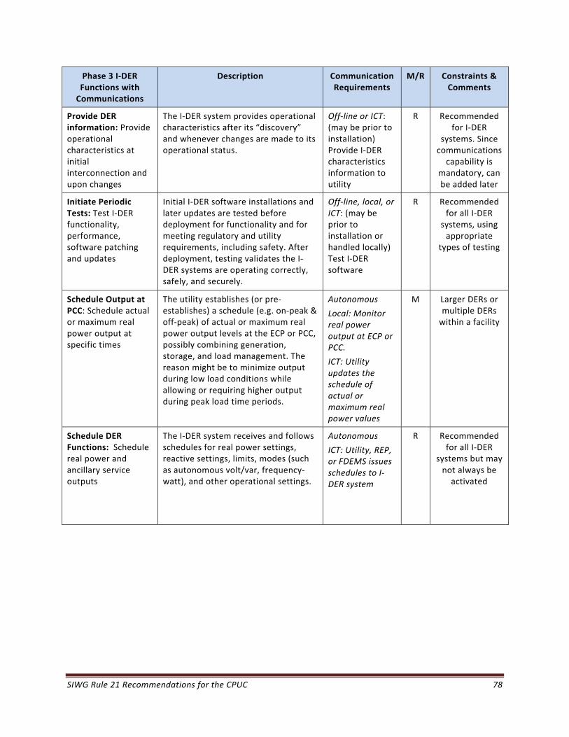
SIWG Rule 21 Recommendations for the CPUC 78
Phase 3 I‐DER Functions with Communications
Description Communication Requirements
M/R Constraints & Comments
Provide DER information: Provide operational characteristics at initial interconnection and upon changes
The I‐DER system provides operational characteristics after its “discovery” and whenever changes are made to its operational status.
Off‐line or ICT: (may be prior to installation) Provide I‐DER characteristics information to utility
R Recommended for I‐DER
systems. Since communications capability is
mandatory, can be added later
Initiate Periodic Tests: Test I‐DER functionality, performance, software patching and updates
Initial I‐DER software installations and later updates are tested before deployment for functionality and for meeting regulatory and utility requirements, including safety. After deployment, testing validates the I‐DER systems are operating correctly, safely, and securely.
Off‐line, local, or ICT: (may be prior to installation or handled locally) Test I‐DER software
R Recommended for all I‐DER
systems, using appropriate
types of testing
Schedule Output at PCC: Schedule actual or maximum real power output at specific times
The utility establishes (or pre‐establishes) a schedule (e.g. on‐peak & off‐peak) of actual or maximum real power output levels at the ECP or PCC, possibly combining generation, storage, and load management. The reason might be to minimize output during low load conditions while allowing or requiring higher output during peak load time periods.
Autonomous
Local: Monitor real power output at ECP or PCC.
ICT: Utility updates the schedule of actual or maximum real power values
M Larger DERs or multiple DERs within a facility
Schedule DER Functions: Schedule real power and ancillary service outputs
The I‐DER system receives and follows schedules for real power settings, reactive settings, limits, modes (such as autonomous volt/var, frequency‐watt), and other operational settings.
Autonomous
ICT: Utility, REP, or FDEMS issues schedules to I‐DER system
R Recommended for all I‐DER
systems but may not always be activated

SIWG Rule 21 Recommendations for the CPUC 79
Phase 3 I‐DER Functions with Communications
Description Communication Requirements
M/R Constraints & Comments
Schedule Storage: Set or schedule the storage of energy for later delivery, indicating time to start charging, charging rate and/or “charge‐by” time
For a I‐DER system that has storage capabilities, such as battery storage or a combined PV + storage system or a fleet of electric vehicles. Preset time‐of‐charge values can be established. Settings are coordinated between the utility and I‐DER operator. Different scenarios could include:
Low load conditions at night are causing some renewable energy to be wasted, so charging energy storage I‐DER systems at that time makes power system operations more efficient.
I‐DER controller charges at the specified rate (less than or equal to the maximum charging rate) until the state‐of‐charge (SOC) reaches a specified level.
I‐DER controller charges at the necessary rate in order to reach the specified SOC within the “charge‐by” time.
Autonomous
ICT: Utility updates the storage settings and/or schedule
R Recommended for I‐DER
systems with storage
capabilities
A.4 Phase 3: Additional Autonomous I-DER Functions
It is recommended that the Phase 3 additional autonomous I‐DER functions shown in Table 19 should be required (M in the Table) or recommended (R in the Table) in Rule 21 such that utilities may specify them for new implementations of inverter‐based I‐DER systems, even though these functions may not necessarily be immediately activated.
Table 19: Phase 3 Additional Autonomous I‐DER functions
Phase 3 Autonomous I‐DER Functions
Description Communication Requirements
M/R Constraints & Comments
Frequency‐Watt: Counteract frequency excursions beyond normal limits by decreasing or increasing real power
The I‐DER system reduces real power to counteract frequency excursions beyond normal limits (and vice versa if additional generation or storage is available), particularly for microgrids. Hysteresis can be used as the frequency returns within the normal range to avoid abrupt changes by groups of I‐DER systems.
Autonomous
Local: Monitor voltage anomalies
ICT: Utility updates frequency response settings
M All I‐DER systems but may not always be activated
(E)
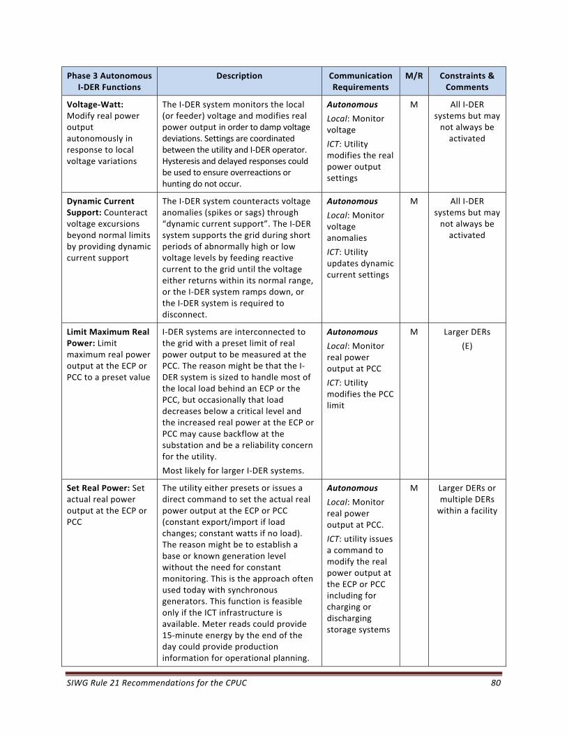
SIWG Rule 21 Recommendations for the CPUC 80
Phase 3 Autonomous I‐DER Functions
Description Communication Requirements
M/R Constraints & Comments
Voltage‐Watt: Modify real power output autonomously in response to local voltage variations
The I‐DER system monitors the local (or feeder) voltage and modifies real power output in order to damp voltage deviations. Settings are coordinated between the utility and I‐DER operator. Hysteresis and delayed responses could be used to ensure overreactions or hunting do not occur.
Autonomous
Local: Monitor voltage
ICT: Utility modifies the real power output settings
M All I‐DER systems but may not always be activated
Dynamic Current Support: Counteract voltage excursions beyond normal limits by providing dynamic current support
The I‐DER system counteracts voltage anomalies (spikes or sags) through “dynamic current support”. The I‐DER system supports the grid during short periods of abnormally high or low voltage levels by feeding reactive current to the grid until the voltage either returns within its normal range, or the I‐DER system ramps down, or the I‐DER system is required to disconnect.
Autonomous
Local: Monitor voltage anomalies
ICT: Utility updates dynamic current settings
M All I‐DER systems but may not always be activated
Limit Maximum Real Power: Limit maximum real power output at the ECP or PCC to a preset value
I‐DER systems are interconnected to the grid with a preset limit of real power output to be measured at the PCC. The reason might be that the I‐DER system is sized to handle most of the local load behind an ECP or the PCC, but occasionally that load decreases below a critical level and the increased real power at the ECP or PCC may cause backflow at the substation and be a reliability concern for the utility.
Most likely for larger I‐DER systems.
Autonomous
Local: Monitor real power output at PCC
ICT: Utility modifies the PCC limit
M
Larger DERs
(E)
Set Real Power: Set actual real power output at the ECP or PCC
The utility either presets or issues a direct command to set the actual real power output at the ECP or PCC (constant export/import if load changes; constant watts if no load). The reason might be to establish a base or known generation level without the need for constant monitoring. This is the approach often used today with synchronous generators. This function is feasible only if the ICT infrastructure is available. Meter reads could provide 15‐minute energy by the end of the day could provide production information for operational planning.
Autonomous
Local: Monitor real power output at PCC.
ICT: utility issues a command to modify the real power output at the ECP or PCC including for charging or discharging storage systems
M Larger DERs or multiple DERs within a facility
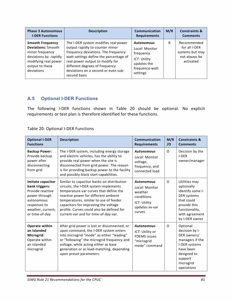
SIWG Rule 21 Recommendations for the CPUC 81
Phase 3 Autonomous I‐DER Functions
Description Communication Requirements
M/R Constraints & Comments
Smooth Frequency Deviations: Smooth minor frequency deviations by rapidly modifying real power output to these deviations
The I‐DER system modifies real power output rapidly to counter minor frequency deviations. The frequency‐watt settings define the percentage of real‐power output to modify for different degrees of frequency deviations on a second or even sub‐second basis
Autonomous
Local: Monitor frequency
ICT: Utility updates the frequency‐watt settings
R
Recommended for all I‐DER
systems but may not always be activated
A.5 Optional I-DER Functions
The following I‐DER functions shown in Table 20 should be optional. No explicit requirements or test plan is therefore identified for these functions.
Table 20: Optional I‐DER Functions
Optional I‐DER Functions
Description Communication Requirements
M/R/O
Constraints & Comments
Backup Power: Provide backup power after disconnecting from grid
The I‐DER system, including energy storage and electric vehicles, has the ability to provide real power when the site is disconnected from grid power. The reason is for providing backup power to the facility and possibly black start capabilities.
Autonomous
Local: Monitor voltage, frequency, and connected load
O Decision by the I‐DER owner/manager
Imitate capacitor bank triggers: Provide reactive power through autonomous responses to weather, current, or time‐of‐day
Similar to capacitor banks on distribution circuits, the I‐DER system implements temperature‐var curves that define the reactive power for different ambient temperatures, similar to use of feeder capacitors for improving the voltage profile. Curves could also be defined for current‐var and for time‐of‐day‐var.
Autonomous
Local: Monitor weather conditions
ICT: Utility updates xx‐var curves
O Utilities may optionally identify some I‐DER systems that could provide this functionality, with agreement by I‐DER owner
Operate within an Islanded Microgrid: Operate within an islanded microgrid
After grid power is lost or disconnected, or upon command, the I‐DER system enters into microgrid “mode” as either “leading” or “following” the microgrid frequency and voltage, while acting either as base generation or as load‐matching, depending upon preset parameters.
Autonomous
ICT: Utility or FDEMS issues “microgrid mode” command
O Optional decision by I‐DER owners/ managers if the I‐DER systems have been designed to support microgrid operations

SIWG Rule 21 Recommendations for the CPUC 82
Optional I‐DER Functions
Description Communication Requirements
M/R/O
Constraints & Comments
Provide low cost energy
Utility, REP, or FDEMS determines which I‐DER systems are to generate how much energy over what time period in order to minimize energy costs. Some I‐DER systems, such as PV systems, would provide low cost energy autonomously, while storage systems would need to be managed.
Autonomous for renewables
ICT: Utility or REP issues real power output requirement to other I‐DER systems
O Optional, market driven, and based on capabilities of the I‐DER systems
Provide low emissions energy
Utility, REP, or FDEMS determines which non‐renewable I‐DER systems are to generate how much energy in order to minimize emissions. Renewable I‐DER systems would operate autonomously.
Autonomous for renewables
ICT: Utility or REP issues real power output level to other I‐DER systems
O Optional, market driven, and based on capabilities of the I‐DER systems
Provide renewable energy
Utility, REP, or FDEMS selects which non‐renewable I‐DER systems are to generate how much energy in order to maximize the use of renewable energy. Renewable I‐DER systems would operate autonomously.
Autonomous for renewables
ICT: Utility or REP issues real power output level to other I‐DER systems
O Optional, market driven, and based on capabilities of the I‐DER systems
Execute schedules: Scheduled, planned, or forecast of available energy and ancillary services
The FDEMS provides scheduled, planned, and/or forecast information for available energy and ancillary services over the next hours, days, weeks, etc., for input into planning applications. Separate I‐DER generation from load behind the PCC. This function is feasible only if the ICT infrastructure is available.
ICT: FDEMS provides information to utility and/or REP
O Optional, market driven, and based on capabilities of the I‐DER systems
Issue generation and storage schedules
The I‐DER system provides schedules of expected generation and storage reflecting customer requirements, maintenance, local weather forecasts, etc. This function is feasible only if the ICT infrastructure is available.
ICT: Provide scheduling information to Utility, REP, or FDEMS
O Optional, and may not always be activated
Provide black start capabilities
The I‐DER system operates as a microgrid (possibly just itself) and supports additional loads being added, so long as they are within its generation capabilities. This function is feasible only if the ICT infrastructure is available.
ICT: Utility issues “black start mode” command
O Optional, market driven, and based on capabilities of the I‐DER systems

SIWG Rule 21 Recommendations for the CPUC 83
Optional I‐DER Functions
Description Communication Requirements
M/R/O
Constraints & Comments
Participate in AGC: Support frequency regulation by automatic generation control (AGC) commands
The I‐DER system (or aggregations of I‐DER systems) implements modification of real‐power output based on AGC signals on a multi‐second basis. This function is feasible only if the ICT infrastructure is available.
ICT: Utility issues AGC commands to modify real power output
O Utilities may identify some I‐DER systems to provide this functionality, with agreement by I‐DER owner
Provide “spinning” or operational reserve as bid into market
The I‐DER system provides emergency real power upon command at short notice (seconds or minutes), either through increasing generation or discharging storage devices. This function would be in response to market bids for providing this reserve. This function is feasible only if the ICT infrastructure is available.
ICT: Utility issues command for emergency reserve
O Optional, market driven, and based on capabilities of the I‐DER systems
Respond to Pricing Signals: Manage real power output based on demand response (DR) pricing signals
The I‐DER system receives a demand response (DR) pricing signal from a utility or retail energy provider (REP) for a time period in the future and determines what real power to output at that time. This function is feasible only if the ICT infrastructure is available.
ICT: Utility or REP issues DR pricing signal
O Optional, market driven, and based on capabilities of the I‐DER systems
Respond to Pricing Signals: Manage selected ancillary services based on demand response (DR) pricing signals
The I‐DER system receives a DR pricing signal from a utility or retail energy provider (REP) for a time period in the future and determines what ancillary services to provide at that time. This function is feasible only if the ICT infrastructure is available.
ICT: Utility or REP issues DR pricing signal
O Optional, market driven, and based on capabilities of the I‐DER systems
Registration: Initiate automated “discovery” of I‐DER systems
The I‐DER system supports its automated “discovery” as interconnected to a location on the power system and initiates the integration process.
This function is feasible only if the ICT infrastructure is available. Otherwise, manual methods must be used.
Off‐line or ICT: Utility, REP, or FDEMS “discovers” a new or moved I‐DER system
O Optional for I‐DER systems. Since communications capability is mandatory, can be added later

SIWG Rule 21 Recommendations for the CPUC 84
B. Appendix B: Definitions of Terms and Acronyms
Term Definition
Anti‐islanding Protection to prevent a I‐DER from energizing an unintentional electrical island
Area EPS Area Electric Power System, an EPS that serves Local EPSs. It is alternately referred to as the utility grid or the distribution power system. It is separated from the Local EPS at the Point of Common Coupling (PCC)
Area EPS Operator The entity responsible for designing, building, operating, and maintaining the Area EPS
Cease to Energize Condition where the DER remains connected but not providing voltage at the ECP. No mandatory time delays are required for reconnection following a Cease to Energize condition.
Cease to Export Condition where there will be no net export of current at the PCC (would require an isolation device at the PCC). The DER is allowed to continue to provide power to local loads. No mandatory time delays for reconnection are required following a Cease to Export condition.
CEC California Energy Commission
Clearing Disconnecting
Connected Condition of the DER system during which it is electrically linked to an EPS through an ECP.
CPUC California Public Utilities Commission
CVR Conservation Voltage Reduction
DER Distributed Energy Resource. Sources of electric power that are not directly connected to a bulk power transmission system. DER includes both generators and energy storage technologies, and sometimes may include controllable loads.
Disconnected Condition of the DER system during which all connections to the EPS are removed or galvanically isolated.
Disconnected
Condition of the DER system during which output of the DER to the EPS is de‐energized or galvanically isolated. A disconnect condition results in a mandatory time delay before reconnection.
DOE Department of Energy
ECP Electrical Connection Point
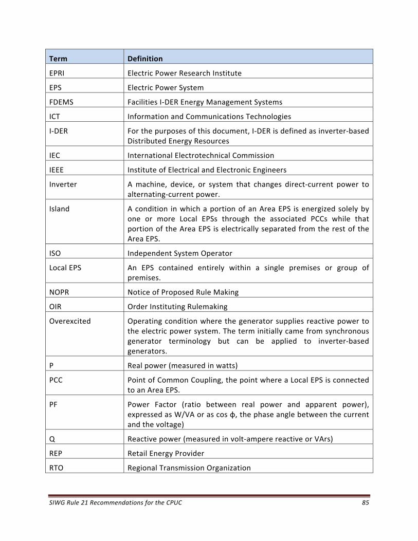
SIWG Rule 21 Recommendations for the CPUC 85
Term Definition
EPRI Electric Power Research Institute
EPS Electric Power System
FDEMS Facilities I‐DER Energy Management Systems
ICT Information and Communications Technologies
I‐DER For the purposes of this document, I‐DER is defined as inverter‐based Distributed Energy Resources
IEC International Electrotechnical Commission
IEEE Institute of Electrical and Electronic Engineers
Inverter A machine, device, or system that changes direct‐current power to alternating‐current power.
Island A condition in which a portion of an Area EPS is energized solely by one or more Local EPSs through the associated PCCs while that portion of the Area EPS is electrically separated from the rest of the Area EPS.
ISO Independent System Operator
Local EPS An EPS contained entirely within a single premises or group of premises.
NOPR Notice of Proposed Rule Making
OIR Order Instituting Rulemaking
Overexcited Operating condition where the generator supplies reactive power to the electric power system. The term initially came from synchronous generator terminology but can be applied to inverter‐based generators.
P Real power (measured in watts)
PCC Point of Common Coupling, the point where a Local EPS is connected to an Area EPS.
PF Power Factor (ratio between real power and apparent power), expressed as W/VA or as cos φ, the phase angle between the current and the voltage)
Q Reactive power (measured in volt‐ampere reactive or VArs)
REP Retail Energy Provider
RTO Regional Transmission Organization
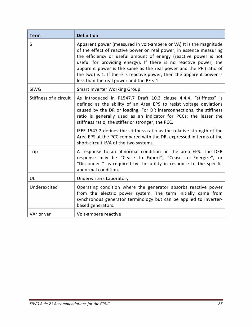
SIWG Rule 21 Recommendations for the CPUC 86
Term Definition
S Apparent power (measured in volt‐ampere or VA) It is the magnitude of the effect of reactive power on real power, in essence measuring the efficiency or useful amount of energy (reactive power is not useful for providing energy). If there is no reactive power, the apparent power is the same as the real power and the PF (ratio of the two) is 1. If there is reactive power, then the apparent power is less than the real power and the PF < 1.
SIWG Smart Inverter Working Group
Stiffness of a circuit As introduced in P1547.7 Draft 10.3 clause 4.4.4, “stiffness” is defined as the ability of an Area EPS to resist voltage deviations caused by the DR or loading. For DR interconnections, the stiffness ratio is generally used as an indicator for PCCs; the lesser the stiffness ratio, the stiffer or stronger, the PCC.
IEEE 1547.2 defines the stiffness ratio as the relative strength of the Area EPS at the PCC compared with the DR, expressed in terms of the short‐circuit kVA of the two systems.
Trip A response to an abnormal condition on the area EPS. The DER response may be “Cease to Export”, “Cease to Energize”, or “Disconnect” as required by the utility in response to the specific abnormal condition.
UL Underwriters Laboratory
Underexcited Operating condition where the generator absorbs reactive power from the electric power system. The term initially came from synchronous generator terminology but can be applied to inverter‐based generators.
VAr or var Volt‐ampere reactive

SIWG Rule 21 Recommendations for the CPUC 87
C. Appendix C: Smart Inverter Working Group Participants
The following list includes all participants in the Smart Inverter Working Group through December 2013.
Table 21: List of SIWG Participants
Company Name
AEI Bill Randle
AEI Christopher Heinzer
AEI John Foster
AEI Michael Mills‐Price
APS David Narang
APS Jihad Zaghloul
APS Marques Montes
Aspen Ashley Spaulding
ASU Faraz Ebneali
Balch Leonard Tillman
Black & Veatch Dan Wilson
Black & Veatch E.A. Sutton
Bloom Energy Carl Cottuli
Bloom Energy Prasad PMSVVSV
Bloom Energy Rajesh Gopinath
Bonfiglioli Bryce Laber
Bonfiglioli Elie Nasr
Bonfiglioli Matthew Charles
Bonfiglioli Patrick McGinn
California Energy Commission John Mathias
California Energy Commission Linda Kelly
California Energy Commission Matt Coldwell
California Energy Commission Rachel MacDonald
California Energy Commission Robert Elliot
California Independent System Operator Dennis Peters
California Independent System Operator John Blatchford
California Public Utilities Commission Anthony Mazy
California Public Utilities Commission Charles Mee
California Public Utilities Commission Connie Chen
California Public Utilities Commission Jamie Ormond
California Public Utilities Commission Keith White
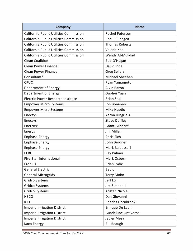
SIWG Rule 21 Recommendations for the CPUC 88
Company Name
California Public Utilities Commission Rachel Peterson
California Public Utilities Commission Radu Ciupagea
California Public Utilities Commission Thomas Roberts
California Public Utilities Commission Valerie Kao
California Public Utilities Commission Wendy Al‐Mukdad
Clean Coalition Bob O'Hagan
Clean Power Finance David Inda
Clean Power Finance Greg Sellers
Consultant* Michael Sheehan
CPUC Ryan Yamamoto
Department of Energy Alvin Razon
Department of Energy Guohui Yuan
Electric Power Research Institute Brian Seal
Empower Micro Systems Jon Bonanno
Empower Micro Systems Mika Nuotio
Enecsys Aaron Jungrieis
Enecsys Steve Deffley
EnerNex Grant Gilchrist
Enesys Jim Miller
Enphase Energy Chris Eich
Enphase Energy John Berdner
Enphase Energy Mark Baldassari
FERC Ray Palmer
Five Star International Mark Osborn
Fronius Brian Lydic
General Electric Bebic
General Microgrids Terry Mohn
Gridco Systems Jeff Lo
Gridco Systems Jim Simonelli
Gridco Systems Kristen Nicole
HECO Dan Giovanni
ICFI Charles Hornbrook
Imperial Irrigation District Enrique De Leon
Imperial Irrigation District Guadelupe Ontiveros
Imperial Irrigation District Javier Meza
Kaco Energy Bill Reaugh
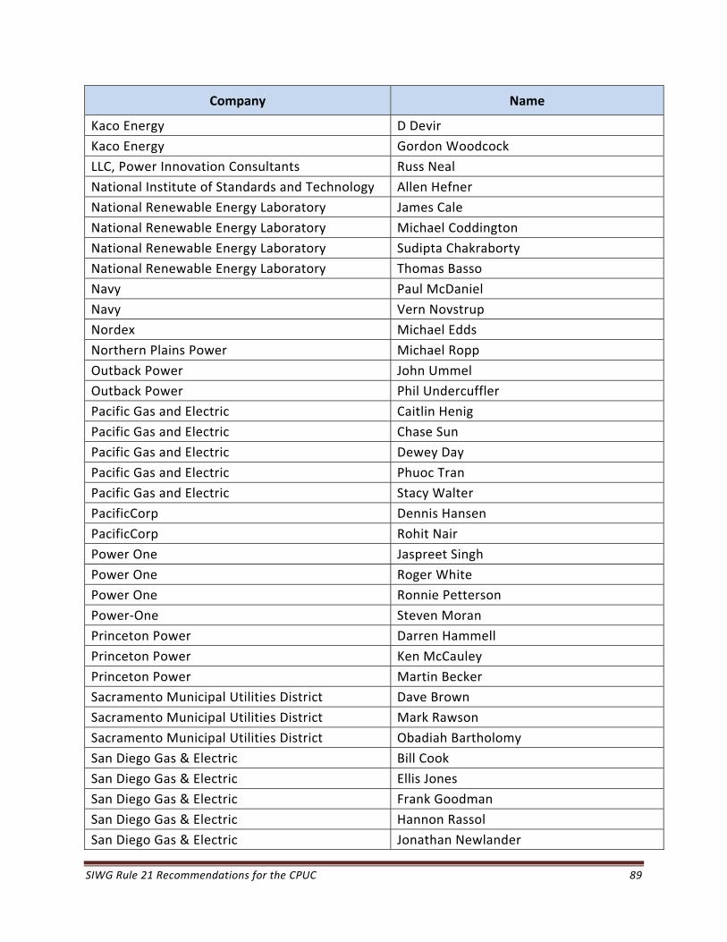
SIWG Rule 21 Recommendations for the CPUC 89
Company Name
Kaco Energy D Devir
Kaco Energy Gordon Woodcock
LLC, Power Innovation Consultants Russ Neal
National Institute of Standards and Technology Allen Hefner
National Renewable Energy Laboratory James Cale
National Renewable Energy Laboratory Michael Coddington
National Renewable Energy Laboratory Sudipta Chakraborty
National Renewable Energy Laboratory Thomas Basso
Navy Paul McDaniel
Navy Vern Novstrup
Nordex Michael Edds
Northern Plains Power Michael Ropp
Outback Power John Ummel
Outback Power Phil Undercuffler
Pacific Gas and Electric Caitlin Henig
Pacific Gas and Electric Chase Sun
Pacific Gas and Electric Dewey Day
Pacific Gas and Electric Phuoc Tran
Pacific Gas and Electric Stacy Walter
PacificCorp Dennis Hansen
PacificCorp Rohit Nair
Power One Jaspreet Singh
Power One Roger White
Power One Ronnie Petterson
Power‐One Steven Moran
Princeton Power Darren Hammell
Princeton Power Ken McCauley
Princeton Power Martin Becker
Sacramento Municipal Utilities District Dave Brown
Sacramento Municipal Utilities District Mark Rawson
Sacramento Municipal Utilities District Obadiah Bartholomy
San Diego Gas & Electric Bill Cook
San Diego Gas & Electric Ellis Jones
San Diego Gas & Electric Frank Goodman
San Diego Gas & Electric Hannon Rassol
San Diego Gas & Electric Jonathan Newlander
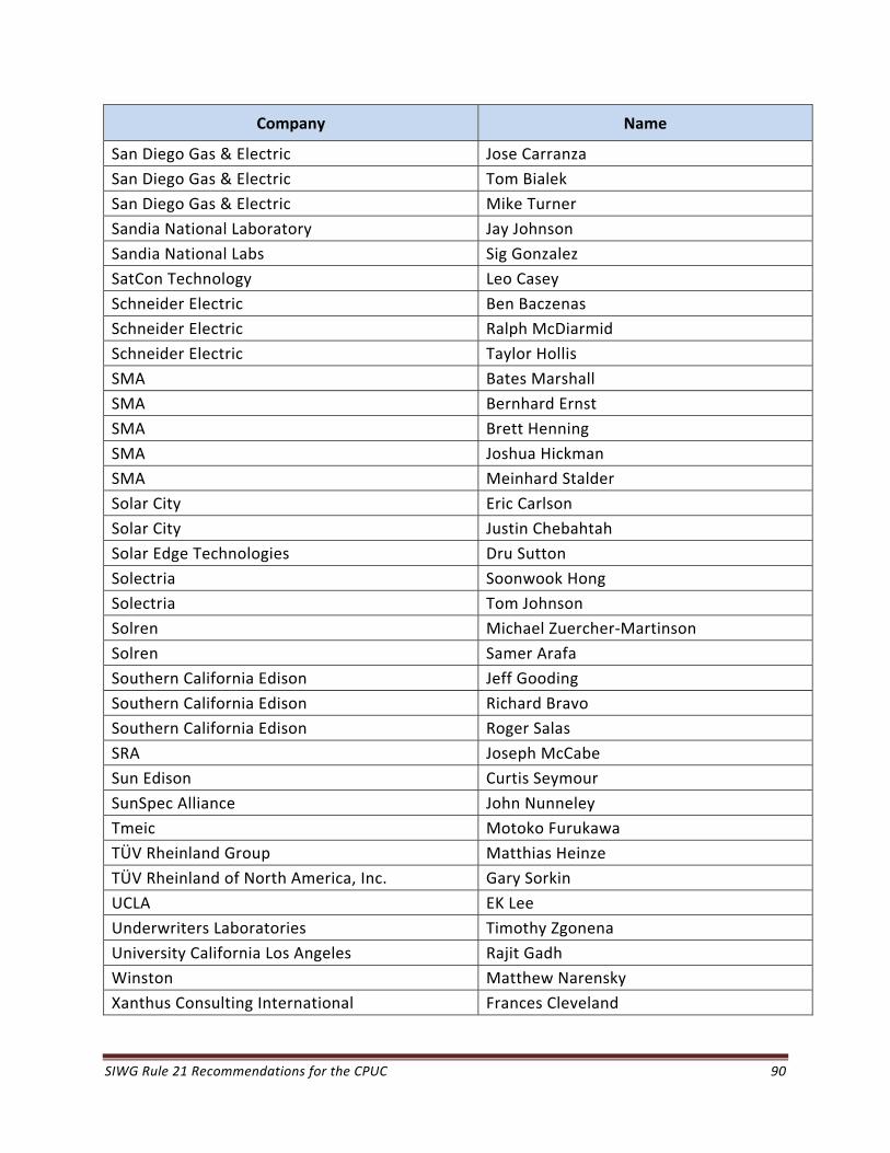
SIWG Rule 21 Recommendations for the CPUC 90
Company Name
San Diego Gas & Electric Jose Carranza
San Diego Gas & Electric Tom Bialek
San Diego Gas & Electric Mike Turner
Sandia National Laboratory Jay Johnson
Sandia National Labs Sig Gonzalez
SatCon Technology Leo Casey
Schneider Electric Ben Baczenas
Schneider Electric Ralph McDiarmid
Schneider Electric Taylor Hollis
SMA Bates Marshall
SMA Bernhard Ernst
SMA Brett Henning
SMA Joshua Hickman
SMA Meinhard Stalder
Solar City Eric Carlson
Solar City Justin Chebahtah
Solar Edge Technologies Dru Sutton
Solectria Soonwook Hong
Solectria Tom Johnson
Solren Michael Zuercher‐Martinson
Solren Samer Arafa
Southern California Edison Jeff Gooding
Southern California Edison Richard Bravo
Southern California Edison Roger Salas
SRA Joseph McCabe
Sun Edison Curtis Seymour
SunSpec Alliance John Nunneley
Tmeic Motoko Furukawa
TÜV Rheinland Group Matthias Heinze
TÜV Rheinland of North America, Inc. Gary Sorkin
UCLA EK Lee
Underwriters Laboratories Timothy Zgonena
University California Los Angeles Rajit Gadh
Winston Matthew Narensky
Xanthus Consulting International Frances Cleveland
Related Documents