Geotechnical Engineering Office, Civil Engineering and Development Department The Government of the Hong Kong Special Administrative Region GEO Technical Guidance Note No. 32 (TGN 32) Updating of Geoguide 4 – Guide to Cavern Engineering Issue No.: 1 Revision: - Date: 17.1.2012 Page: 1 of 16 1. SCOPE 1.1 This Technical Guidance Note (TGN) supplements the guidelines given in Geoguide 4 - Guide to Cavern Engineering. 1.2 Any feedback on this TGN should be directed to Chief Geotechnical Engineer/Planning of the GEO. 2. TECHNICAL POLICY 2.1 The technical recommendations promulgated in this TGN were agreed by GEO Geotechnical Control Conference on 4 January 2012. 3. RELATED DOCUMENTS 3.1 ASTM Standard D7625-10 (2010). Standard Test Method for Laboratory Determination of Abrasiveness of Rock Using the CERCHAR Method. ASTM International, West Conshohocken, PA, DOI: 10.1520/D7625-10 3.2 Bandis, S.C., Sharp, J.C., Schinas, C.A., Hardingham, A.D., Kennington, G.J., Storry, R.B. (2000). Design and construction of large span tunnel portals for West Rail. Proceedings of the IMMHK Conference on Engineering Geology HK 2000, IMMHK, pp 47-61. 3.3 Barton, N., Lien, R. & Lunde, J. (1974). Engineering classification of rock masses for the design of tunnel support. Rock Mechanics. 6(4), pp 189-236. 3.4 Barton, N. & Bieniawski, Z.T. (2008). RMR and Q – Setting records straight. Tunnels and Tunnelling International, Feb. 2008, pp 26-29. 3.5 Bieniawski, Z.T. (1976). Rock mass classification in rock engineering. Proceedings of the Symposium on Exploration for Rock Engineering. Johannesburg, vol. 1, pp 97-106. 3.6 Free, M.W., Haley, J., Klee, G. & Rummel, F. (2000). Determination of in situ stress in jointed rock in Hong Kong using hydraulic fracturing and over-coring methods. Proceedings of the Conference on Engineering Geology HK 2000, Institution of Mining and Metallurgy, Hong Kong Branch, pp 31-45. 3.7 Garshol, K.F. (2007). Pre-excavation grouting in rock-tunnelling. UGC International Division of BASF Construction, Zürich, Switzerland. 3.8 GCO (1987). Guide to Site Investigation (Geoguide 2). Geotechnical Control Office, Hong Kong, 365 p. [\\CEDD4722\TGN\TGN32_FINAL.docx][17.1.2012][KJR]

Welcome message from author
This document is posted to help you gain knowledge. Please leave a comment to let me know what you think about it! Share it to your friends and learn new things together.
Transcript

Geotechnical Engineering Office, Civil Engineering and Development Department
The Government of the Hong Kong Special Administrative Region
GEO Technical Guidance Note No. 32 (TGN 32)
Updating of Geoguide 4 – Guide to Cavern Engineering
Issue No.: 1 Revision: - Date: 17.1.2012 Page: 1 of 16
1. SCOPE
1.1 This Technical Guidance Note (TGN) supplements the guidelines given in Geoguide 4 -
Guide to Cavern Engineering.
1.2 Any feedback on this TGN should be directed to Chief Geotechnical Engineer/Planning of
the GEO.
2. TECHNICAL POLICY
2.1 The technical recommendations promulgated in this TGN were agreed by GEO
Geotechnical Control Conference on 4 January 2012.
3. RELATED DOCUMENTS
3.1 ASTM Standard D7625-10 (2010). Standard Test Method for Laboratory Determination
of Abrasiveness of Rock Using the CERCHAR Method. ASTM International, West
Conshohocken, PA, DOI: 10.1520/D7625-10
3.2 Bandis, S.C., Sharp, J.C., Schinas, C.A., Hardingham, A.D., Kennington, G.J., Storry, R.B.
(2000). Design and construction of large span tunnel portals for West Rail. Proceedings of
the IMMHK Conference on Engineering Geology HK 2000, IMMHK, pp 47-61.
3.3 Barton, N., Lien, R. & Lunde, J. (1974). Engineering classification of rock masses for the
design of tunnel support. Rock Mechanics. 6(4), pp 189-236.
3.4 Barton, N. & Bieniawski, Z.T. (2008). RMR and Q – Setting records straight. Tunnels and
Tunnelling International, Feb. 2008, pp 26-29.
3.5 Bieniawski, Z.T. (1976). Rock mass classification in rock engineering. Proceedings of the
Symposium on Exploration for Rock Engineering. Johannesburg, vol. 1, pp 97-106.
3.6 Free, M.W., Haley, J., Klee, G. & Rummel, F. (2000). Determination of in situ stress in
jointed rock in Hong Kong using hydraulic fracturing and over-coring methods.
Proceedings of the Conference on Engineering Geology HK 2000, Institution of Mining
and Metallurgy, Hong Kong Branch, pp 31-45.
3.7 Garshol, K.F. (2007). Pre-excavation grouting in rock-tunnelling. UGC International
Division of BASF Construction, Zürich, Switzerland.
3.8 GCO (1987). Guide to Site Investigation (Geoguide 2). Geotechnical Control Office,
Hong Kong, 365 p.
[\\CEDD4722\TGN\TGN32_FINAL.docx][17.1.2012][KJR]

Geotechnical Engineering Office, Civil Engineering and Development Department
The Government of the Hong Kong Special Administrative Region
GEO Technical Guidance Note No. 32 (TGN 32)
Updating of Geoguide 4 – Guide to Cavern Engineering
Issue No.: 1 Revision: - Date: 17.1.2012 Page: 2 of 16
3.9 GEO (1992). Guide to Cavern Engineering (Geoguide 4). Geotechnical Engineering
Office, Hong Kong, 156 p.
3.10 GEO (2007). Engineering Geological Practice in Hong Kong (GEO Publication No.
1/2007). Geotechnical Engineering Office, Hong Kong, 278 p.
3.11 GEO (2009a). Geoguide 2 - Guide to Site Investigation Updated Appendix B: Sources of
Information. GEO Technical Guidance Note No. 5 (TGN 5), Geotechnical Engineering
Office, Hong Kong, 359 p.
3.12 GEO (2009b). Site Investigation for Tunnel Works. Technical Guidance Note No. 24
(TGN 24), Geotechnical Engineering Office, Hong Kong, 9 p.
3.13 GEO (2010). New Control Framework for Soil Slopes Subjected to Blasting Vibration.
Technical Guidance Note No. 28 (TGN 28), Geotechnical Engineering Office, Hong Kong,
4 p.
3.14 Grimstad, E. & Barton, N. (1993). Updating the Q-system for NMT. International
Symposium on Sprayed Concrete (eds. Kompen, Opsahl and Berg), 89, A30-36
3.15 Grimstad, E., Bhasin, R., Hagen, A.W., Kayna, A. & Kankes, K. (2003). Q-system
advance for sprayed lining. Tunnels and Tunnelling International, Part 1 - January 2003
and Part II - March 2003.
3.16 Hardingham, A.D., Sharp, J.C., Sekula, J., Bandis, S.C. & Sin, S. (1998). Lai King rock
tunnel complex - design and construction. Proceedings of the HKIE Geotechnical Division
Seminar on Geotechnical Aspects of the Airport Core Projects, Hong Kong, pp 1-18.
3.17 Hoek, E. (1994). Strength of rock and rock masses. ISRM News Journal, 2(2), pp 4-16.
3.18 Hoek, E. (2007). Practical Rock Engineering. Rocscience.
3.19 Hoek, E. & Brown E.T. (1980). Underground Excavations in Rock. Institution of
Mining and Metallurgy, London, 536 p.
3.20 Hoek, E., Kaiser, P.K. & Bawden, W.F. (1995). Support of Underground Excavations in
Hard Rock. Rotterdam, Balkema, 215 p.
3.21 ISRM (1981). Rock Characterization Testing and Monitoring: ISRM Suggested Methods,
edited by E.T. Brown. Pergamon Press, Oxford, 211 p.
3.22 ISRM (2007). The Complete ISRM Suggested Methods for Rock Characterisation,
Testing and Monitoring: 1974 – 2006, edited by Ulusay, R. & Hudson, J.A. ISRM Turkish
National Group, Ankara, Turkey, 628 p.
[\\CEDD4722\TGN\TGN32_FINAL.docx][17.1.2012][KJR]

Geotechnical Engineering Office, Civil Engineering and Development Department
The Government of the Hong Kong Special Administrative Region
GEO Technical Guidance Note No. 32 (TGN 32)
Updating of Geoguide 4 – Guide to Cavern Engineering
Issue No.: 1 Revision: - Date: 17.1.2012 Page: 3 of 16
3.23 Klee, G., Rummel, F. & Williams, A. (1999). Hydraulic fracturing stress measurements
in Hong Kong. International Journal of Rock Mechanics and Mining Sciences, vol. 36, pp
731-741.
3.24 Marinos, P. & Hoek, E. (2000). GSI – A geologically friendly tool for rock mass strength
estimation. Proceedings of GeoEng 2000 Conference, Melbourne, pp 1422-1442.
3.25 Norwegian Tunnelling Society (2004). Water Control. Publication No. 12. 101 p.
3.26 Norwegian Tunnelling Society (2010). Rock Support in Norwegian Tunnelling.
Publication No. 19. 88 p.
3.27 Norwegian Tunnelling Society (2011). Rock Mass Grouting. Publication No. 20.
106 p.
3.28 Ove Arup & Partners Ltd. (2011). Working Paper No. 4 – Review of Geoguide 4:
Guide to Cavern Engineering. Agreement No. CE66/2009(GE) Enhanced Use of
Underground Space in Hong Kong – Feasibility Study. Geotechnical Engineering Office,
Hong Kong, 37 p. plus Appendices.
3.29 Palmström, A. (1995). Characterising rock masses by the RMi for use in Practical Rock
Engineering, Part 1: The development of the Rock Mass Index (RMi). Tunnelling and
Underground Space Technology, vol. 11, No. 2, pp 175-188.
3.30 Palmström, A. & Broch, E. (2006). Use and misuse of rock mass classification systems
with particular reference to the Q-system. Tunnelling and Underground Space
Technology, vol. 21, pp 575-593.
3.31 Palmström, A. & Singh, R. (2001). The deformation modulus of rock masses – comparisons between in-situ tests and indirect estimates. Tunnelling and Underground
Space Technology, vol. 16, pp 115-131.
3.32 Palmström, A. & Stille, H. (2010). Rock Engineering. Thomas Telford, London, 408 p.
4. BACKGROUND
4.1 Geoguide 4 (GEO, 1992) provides the recommended standard of good practice for the
civil engineering aspects of rock cavern applications in Hong Kong. It also serves as a
reference document for non-specialists involved in the administration of cavern projects.
The document gives guidance on good engineering practice, and its recommendations are
not intended to be mandatory. It is recognised that experienced practitioners, on whose
judgment the success of any underground excavation depends, may wish to use alternative
methods to those recommended herein.
4.2 In March 2010, GEO commissioned a study on the Enhanced Use of Underground Space in
Hong Kong. One of the requirements under the Brief of the study was to review Geoguide
[\\CEDD4722\TGN\TGN32_FINAL.docx][17.1.2012][KJR]

Geotechnical Engineering Office, Civil Engineering and Development Department
The Government of the Hong Kong Special Administrative Region
GEO Technical Guidance Note No. 32 (TGN 32)
Updating of Geoguide 4 – Guide to Cavern Engineering
Issue No.: 1 Revision: - Date: 17.1.2012 Page: 4 of 16
4, recommend areas for updating and outline major outdated information in the form of a
Working Paper (Ove Arup & Partners Ltd., 2011). The major areas for updating are
described below and summarised in Table 1 (Annex TGN 32 A1).
5. DEFINITIONS
None.
6. TECHNICAL RECOMMENDATIONS
Solid Geology (Section 2.2.1 of Geoguide 4)
6.1 GEO Technical Guidance Note No. 5 (GEO, 2009a) provides an update on the sources of
information on geological and related maps and memoirs.
Sources of Information (Section 3.3.2 of Geoguide 4)
6.2 GEO Technical Guidance Note No. 5 (GEO, 2009a) provides an update on the sources of
information for the planning of site investigation in Hong Kong and supersedes
Appendix B: Sources of Information of Geoguide 2 (GCO, 1987).
Field Investigation (Section 3.6 of Geoguide 4)
6.3 References to ISRM (1981) which relates to the complete ISRM suggested methods for
rock characterisation, testing and monitoring should be replaced by ISRM (2007).
6.4 Directional drilling is a major advance in the ground investigation for underground works
that allows control of the direction of long drillholes along the tunnel axis. The technology
makes it possible to drill in a forced straight line as well as controlling the drillhole in one
or more curves, hitting the target with very high precision. Further discussion on
directional drilling is given in GEO Technical Guidance Note, TGN No. 24 (GEO, 2009b)
on Site Investigation for Tunnel Works.
Joint Orientation (Section 3.7.3 of Geoguide 4)
6.5 New and common methods available in Hong Kong include the Acoustic Televiewer and
Optical Televiewer, which are becoming more commonly used compared with
Impression Packers, Core Orientators and Closed Circuit Television Surveying as
described in Section 3.7.3 of Geoguide 4.
Rock Stress Measurement (Sections 3.7.5 and 4.2.6 of Geoguide 4)
Since 1990, additional hydraulic fracture stress measurements to about 200 m depth were
conducted in Hong Kong. The in situ tests were carried out by using the wireline
hydrofracture technique. Klee et al (1999) reported that although the tests were performed
both in fractured and un-fractured crystalline rocks and the drillholes are located in areas of
[\\CEDD4722\TGN\TGN32_FINAL.docx][17.1.2012][KJR]
6.6

Geotechnical Engineering Office, Civil Engineering and Development Department
The Government of the Hong Kong Special Administrative Region
GEO Technical Guidance Note No. 32 (TGN 32)
Updating of Geoguide 4 – Guide to Cavern Engineering
Issue No.: 1 Revision: - Date: 17.1.2012 Page: 5 of 16
pronounced topographical relief, the results yield a consistent orientation of the
maximum horizontal stress of N108°±28°. Above 150 m depth, the vertical stress Sv due
to the weight of the overburden with given rock density is the minimum principal stress,
while the limited amount of deeper data available suggests that the minimum horizontal
principal stress is the least principal stress. Free et al (2000) provided a good summary of
the general in situ stress measurements in Hong Kong and compiled the data from other
references to depict the general major and minor principal stress states for rocks in various
parts of Hong Kong. Figure 1 (Annex TGN 32 A2) shows the general relationship of in
situ stress with depth that has been recorded. This is typical for rock masses at shallow
depth over the majority of the world where due to removal of overburden, the near surface
stresses are higher horizontally than vertically.
Test for Drillability (Section 3.7.12 of Geoguide 4)
6.7 An additional test that can identify the drillability of the rock is the Cerchar test (ASTM
Standard D7625-10, 2010). This test is more commonly used in Hong Kong to assess the
abrasivity and drillability of the rock and hence for assessment of the performance of
Tunnel Boring Machines (TBM) (e.g. TBM penetration/advance rates, cutter wear rates,
etc.).
Rock Classification Systems for Determining Rock Support Requirements (Sections
4.1.4 and 4.5.2 of Geoguide 4)
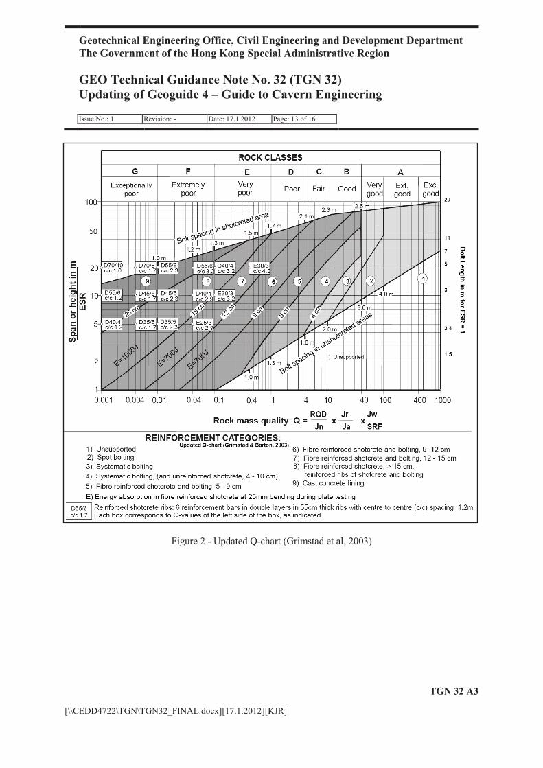
6.8 The Q-system was developed by the Norwegian Geotechnical Institute in the early
1970s (Barton et al, 1974), and a major update was published in 1993 (Grimstad &
Barton, 1993). Guidance on limitations and the proper use of Q-system is also given by
Palmström & Broch (2006) and Barton & Bieniawski (2008). The Q-chart for
estimates of rock support (Grimstad et al, 2003) is presented in Figure 2 (Annex TGN 32
A3).
6.9 The Q-system incorporates the experience obtained from more than 1,000 case histories
from existing tunnels, and an empirically based diagram showing the correspondence of
Q-values and the support used in these cases has been constructed. The diagram also
includes Reinforced Ribs of Sprayed Concrete (RRS), a design which is partly based on
numerical modelling. RRS has been developed for use in very poor to extremely poor
rock conditions for relevant cavern spans, as may be seen from the Q-chart. Situations
where use of the Q-system may not be adequate and software tools may be used to assess
the rock support requirements are discussed in Section 6.20.
Groundwater (Section 4.2.5 of Geoguide 4)
6.10 Reference should be made to Publication No. 12 of the Norwegian Tunnelling Society
(2004) on water control in tunnelling.
RMR Method of Rock Classification (Section 4.5.3 of Geoguide 4)
6.11 Bieniawski (1976) showed that the relationship between the RMR rating and the equivalent
Q-values is given by the following equation:
[\\CEDD4722\TGN\TGN32_FINAL.docx][17.1.2012][KJR]

Geotechnical Engineering Office, Civil Engineering and Development Department
The Government of the Hong Kong Special Administrative Region
GEO Technical Guidance Note No. 32 (TGN 32)
Updating of Geoguide 4 – Guide to Cavern Engineering
Issue No.: 1 Revision: - Date: 17.1.2012 Page: 6 of 16
RMR = 9 loge Q + 44
6.12 Although this may be adequate for many cases, there are some cases where inaccurate
results are found, up to ±50% from the actual value. It is therefore recommended that
rather than using the correlation to derive the corresponding number, the value in
the other classification system should be derived wherever possible by using the values or
ratings of the input parameters for that system. It is more relevant to calculate the RMR
values separately from the input parameters (and vice versa). Useful guidance has also
been given by Hoek (2007) on the use of Q and RMR systems.
The Geological Strength Index (GSI) (New Item under Section 4.5 of Geoguide 4)
6.13 The GSI was introduced to provide a system for estimating rock mass strengths for
different geological conditions as identified by field observations. The GSI ranges from 10
(for extremely poor rock mass) to 100 (for intact rock). The rock mass characterisation is
straightforward and based on the visual appearance of the rock structure, in terms of
blockiness, and the surface condition of the discontinuities as indicated by joint roughness
and alteration. The combination of these two parameters provides a practical basis for
describing a wide range of rock mass types. It should be noted that there is no input for the
strength of the rock material in the GSI system. The GSI chart for jointed rocks (as
proposed by Marinos & Hoek (2000)), is shown in Figure 3 (Annex TGN 32 A4). The
figure provides a list of mechanical rock properties in tabular form, which can be used for
modelling purposes.
The Rock Mass Index, RMi (New Item under Section 4.5 of Geoguide 4)
6.14 The rock mass index (RMi) is a volumetric parameter indicating the approximate uniaxial
compressive strength of a rock mass. The RMi system was formulated by Palmström
(1995) and has since been further developed and presented in several papers. It makes use
of the uniaxial compressive strength of intact rock (sc) and the strength reduction effect of
the joints penetrating the rock (JP).
6.15 The RMi value can be applied as input to other rock engineering methods, such as
numerical modelling, the Hoek-Brown failure criterion for rock masses (Hoek & Brown,
1980), and to estimate the deformation modulus for rock masses (Palmström & Singh,
2001). It can also be used for estimating rock support using a support chart. Further details
are shown in Figure 4 (Annex TGN 32 A5) (Palmström & Stille, 2010).
Numerical Models (Section 4.6.3 of Geoguide 4)
6.16 The development of computer hardware for numerical modelling has resulted in a situation
where computational power and data memory is no longer a limiting factor in numerical
analyses. The development of modelling software has also managed to successfully
combine features from both continuum and discontinuum models allowing more complex
and realistic models to be developed. Lists of currently accepted geotechnical
computer programs, including those with applications in tunnel/cavern construction, for
private and Government works, are respectively given at the following links:
http://www.bd.gov.hk/english/inform/comprogram/agp.pdf and http://geosis.ccgo.hksarg
[\\CEDD4722\TGN\TGN32_FINAL.docx][17.1.2012][KJR]

Geotechnical Engineering Office, Civil Engineering and Development Department
The Government of the Hong Kong Special Administrative Region
GEO Technical Guidance Note No. 32 (TGN 32)
Updating of Geoguide 4 – Guide to Cavern Engineering
Issue No.: 1 Revision: - Date: 17.1.2012 Page: 7 of 16
/hkss/eng/studies/computer_program/accepted_computer_program.htm. Further details of
program application areas and limitations can be obtained from the general registries of
BD and CGE/S&T respectively.
6.17 Different computer models may have respective strengths and weaknesses making them
suitable for different geotechnical design problems. For input parameters to numerical
models, the limiting factor is the heterogeneous nature of the rock mass material, which in
a practical scale is impossible to investigate sufficiently in the field and to represent
realistically in a model.
6.18 Numerical modelling can be a powerful tool in geotechnical design. With recent
software development, it has become more time and cost efficient to utilise numerical
modelling. Despite this, the result of numerical modelling is only indicative of typical
expected rock mass behaviour and the results must be subject to proper interpretation
before it is incorporated in the design.
6.19 Universal Distinct Element Code (UDEC) analysis of jointed rock often produces
conservative analysis as it is based upon 2D representation of the rock masses. The
software tool is useful in understanding the stress changes and how rock blocks will react to
the changes in stress around the excavation. In addition, it provides an essential tool in
examining the rock bolt lengths and support requirements for large span excavations for
which the empirical support charts are less reliable. An example of UDEC analysis for a
large span cavern is shown in Figure 5 (Annex TGN 32 A6).
6.20 Other scenarios, in addition to large span excavations, where software tools should be used
in assessing the rock support requirements include intersections/pillars supports, closely
spaced cavern/tunnel openings, excavations in close proximity to foundations of existing
buildings/structures, excavations under shallow rock cover and mixed ground conditions.
Local case histories of using UDEC are described by Hardingham et al (1998) and Bandis
et al (2000). A three-dimensional version of the program, 3DEC, is also available.
Planning the Excavation (Section 5.2 of Geoguide 4)
6.21 During the past 20 years, there has been a significant development of tunnelling equipment
that should be taken into account during project planning. Typical standard
equipment used during cavern and tunnel construction is described below.
6.22 Computerised drill jumbos are capable of drilling up to 3 m per minute in rock with
uniaxial compressive strength up to 160 MPa. The largest currently available models can
drill close to 200 m2
faces from a single set up and have a maximum drilling height of 13 m.
The computer controlled drilling performance automatically performs alignment for the
next round and surveying of the previous excavated profile.
6.23 Mucking is performed by wheel loader and trucks. Diesel/electric loading equipment is
applied to improve the environment at the tunnel face. A mobile crusher can be installed
underground close to the face and connected to a conveying system. This can reduce the
number of trucks significantly and as a result improve the air quality.
[\\CEDD4722\TGN\TGN32_FINAL.docx][17.1.2012][KJR]

Geotechnical Engineering Office, Civil Engineering and Development Department
The Government of the Hong Kong Special Administrative Region
GEO Technical Guidance Note No. 32 (TGN 32)
Updating of Geoguide 4 – Guide to Cavern Engineering
Issue No.: 1 Revision: - Date: 17.1.2012 Page: 8 of 16
6.24 Support is performed by highly automated and computerised robots for sprayed concrete,
whilst drilling for rock bolts is mainly done by a drill jumbo. For a large cavern complex,
a dedicated rockbolting machine may be preferred especially where the total number of
rockbolts is large. Scaling is normally performed by hydraulic hammers mounted on
excavators, but final scaling by handheld bars is still used.
6.25 Rock mass grouting takes place using computerised units that can mix, agitate and deliver
grout to several grout holes simultaneously upon pre-determined termination criteria in
terms of intake volume, injection pressure or duration. Advances in grouting technology
now allow for higher penetration into the rock mass creating a drier tunnel environment.
This technology is just starting to be introduced to Hong Kong (Norwegian Tunnelling
Society, 2011) and will need further experience before it can be used with confidence.
Concrete Lining (Section 5.6.8 of Geoguide 4)
6.26 Reference should be made to Publication No. 19 of the Norwegian Tunnelling Society
(2010) on the choice of final support and the drainage design of concrete lining.
Blast Vibration Acceptance Criteria (Section 5.7.2 of Geoguide 4)
6.27 There have been further developments in the blasting limits set on soil slopes as outlined in
GEO Technical Guidance Note No. 28 (GEO, 2010), which promulgates a new control
framework for soil slopes subject to blasting vibrations.
Grouts and Grouting (Section 5.8.3 of Geoguide 4)
6.28 The practice of pre-grouting for rock excavations, which is an important construction
element in cavern construction within urban areas, is presented by Garshol (2007).
State-of-the-art grouting being introduced into Hong Kong has also been presented by the
Norwegian Tunnelling Society (2011).
Construction Records (Section 5.12 of Geoguide 4)
6.29 For geological records, GEO has developed a standard electronic template for collection of
tunnel data in the form of a Rock Mass Mapping and Classification Sheet (RMMCS). The
RMMCS is available for downloading from the CEDD website at the following hyperlink:
http://hkss.cedd.gov.hk/hkss/eng/download/rock-mass/GEO_Rock_Mass_Mapping_Prof
orma.xls. The standard template can be modified and used for geological records during
cavern construction.
Exposed Rock Surfaces (Section 6.3.2 of Geoguide 4)
6.30 Within the Stanley Sewage Treatment Plant, which was completed in 1995, there
was an early issue with a minor rockfall incident at the start of the facility operation.
Subsequently, remedial measures were proposed with the application of additional dowels
and shotcrete that were applied over the majority of the exposed rock surfaces in the roof of
the caverns. The original cavern support design was based on the Q-system (Barton, 1974)
that required permanent support of systematic bolting in large areas of the cavern roof,
[\\CEDD4722\TGN\TGN32_FINAL.docx][17.1.2012][KJR]

Geotechnical Engineering Office, Civil Engineering and Development Department
The Government of the Hong Kong Special Administrative Region
GEO Technical Guidance Note No. 32 (TGN 32)
Updating of Geoguide 4 – Guide to Cavern Engineering
Issue No.: 1 Revision: - Date: 17.1.2012 Page: 9 of 16
without shotcrete support. The extensive remedial works that were undertaken whilst the
Sewage Treatment Plant was in operation could have been avoided had the requirement for
rockfall protection been identified during the detailed design stage. The guidance already
provided in Sections 5.6.2 (b) and 5.6.3 of Geoguide 4 should be further emphasized in
Section 6.3.2 of Geoguide 4, stating that the extent of final roof support should be related to
the future use, occupancy and psychological factors, in consultation with the owner.
7 ANNEXES
7.1 TGN 32 A1 – Table 1 – A summary of major updates or proposed new sections for
Geoguide 4
7.2 TGN 32 A2 – Figure 1 – Summary of hydraulic fracturing test data on minimum
horizontal stress ratio Kh (Sh/Sv) versus depth (Free et al, 2000)
7.3 TGN 32 A3 – Figure 2 – Updated Q-chart (Grimstad et al, 2003)
7.4 TGN 32 A4 – Figure 3 – GSI system (Marinos & Hoek, 2000)
7.5 TGN 32 A5 – Figure 4 – RMi system (Palmström & Stille, 2010)
7.6 TGN 32 A6 – Figure 5 – An example of UDEC analysis (for a large span tunnel showing
support loading and displacement contours for staged excavation) (Ove
Arup & Partners Ltd., 2011)
(Y C Chan)
Head, Geotechnical Engineering Office
[\\CEDD4722\TGN\TGN32_FINAL.docx][17.1.2012][KJR]

Geotechnical Engineering Office, Civil Engineering and Development Department
The Government of the Hong Kong Special Administrative Region
GEO Technical Guidance Note No. 32 (TGN 32)
Updating of Geoguide 4 – Guide to Cavern Engineering
Issue No.: 1 Revision: - Date: 17.1.2012 Page: 10 of 16
Table 1 - A summary of major updates or proposed new sections for Geoguide 4
Geoguide 4 (GEO, 1992) Summary of Major Updates or Proposed New Sections
Section 2.2.1 – Solid
Geology
GEO Technical Guidance Note No. 5 (GEO, 2009a) provides an
update on the sources of geological information.
Section 3.3.2 – Sources of Information
GEO Technical Guidance Note No. 5 (GEO, 2009a) provides an
update on the sources of information for the planning of site
investigation in Hong Kong.
Section 3.6 – Field Investigation
References to ISRM (1981) for rock characterisation, testing and
monitoring should be replaced by ISRM (2007).
Directional drilling introduced as a major advance in ground
investigation for underground works.
Section 3.7.3 – Joint Orientation
New and common methods available in Hong Kong include the
Acoustic Televiewer and Optical Televiewer.
Sections 3.7.5 and 4.2.6 – Rock Stress Measurement
Summary of information on in situ stress measurements in Hong
Kong.
Section 3.7.12 – Test for Drillability
An additional test that can identify the drillability of the rock is the
Cerchar test.
Sections 4.1.4 and 4.5.2 – Rock Classification Systems
for Determining Rock
Support Requirements
A major update of the Q-system in 1993. The Q-chart for estimates of
rock support (Grimstad et al, 2003) is presented.
Section 4.2.5 – Groundwater
Reference should be made to Publication No. 12 of the Norwegian
Tunnelling Society (2004) on water control in tunnelling.
Section 4.5.3 – Recommended to derive the RMR values using the values of the input
RMR Method of Rock parameters in that system.
Classification
TGN 32 A1 [1/2]
[\\CEDD4722\TGN\TGN32_FINAL.docx][17.1.2012][KJR]

Geotechnical Engineering Office, Civil Engineering and Development Department
The Government of the Hong Kong Special Administrative Region
GEO Technical Guidance Note No. 32 (TGN 32)
Updating of Geoguide 4 – Guide to Cavern Engineering
Issue No.: 1 Revision: - Date: 17.1.2012 Page: 11 of 16
Geoguide 4 (GEO, 1992) Summary of Major Updates or Proposed New Sections
Section 4.5 – Evaluation of Rock Mass
Quality and Rock Support
New Item: The Geological Strength Index (GSI).
The Geological Strength Index has been introduced to provide a
system for estimating rock mass strengths for different geological
conditions as identified by field observations.
Section 4.5 – Evaluation of Rock Mass
Quality and Rock Support
New Item: The Rock Mass Index (RMi)
The rock mass index is a volumetric parameter indicating the
approximate uniaxial compressive strength of a rock mass.
Section 4.6.3 – Numerical Models
Numerical modelling can be a powerful tool in geotechnical design,
and with recent software development has become more time and cost
efficient to utilise.
Section 5.2 – Planning the Excavation
Significant development of tunnelling equipment/machines have taken
place over the last 20 years.
Section 5.6.8 – Concrete Lining
Reference should be made to Publication No. 19 of the Norwegian
Tunnelling Society (2010) on the choice of final support and the
drainage design of concrete lining.
Section 5.7.2 – GEO Technical Guidance Note No. 28 promulgates a new control
Blast Vibration Acceptance framework for soil slopes subject to blasting vibrations.
Criteria
Section 5.8.3 – Grouts and Grouting
The practice of pre-grouting for rock excavation and the
state-of-the-art grouting are presented by Garshol (2007) and
Norwegian Tunnelling Society (2011) respectively.
Section 5.12 – Construction Records
For geological records, GEO has developed a standard electronic
template for collection of tunnel data in the form of a Rock Mass
Mapping and Classification Sheet.
Section 6.3.2 – Exposed Rock Surfaces
The guidance already provided in Sections 5.6.2 (b) and 5.6.3 of
Geoguide 4 should be further emphasized in Section 6.3.2 of Geoguide
4 stating that the extent of final roof support should be related to the
future use, occupancy and psychological factors.
TGN 32 A1 [2/2]
[\\CEDD4722\TGN\TGN32_FINAL.docx][17.1.2012][KJR]

Geotechnical Engineering Office, Civil Engineering and Development Department
The Government of the Hong Kong Special Administrative Region
GEO Technical Guidance Note No. 32 (TGN 32)
Updating of Geoguide 4 – Guide to Cavern Engineering
Issue No.: 1 Revision: - Date: 17.1.2012 Page: 12 of 16
Figure 1 – Summary of hydraulic fracturing test data on minimum horizontal stress ratio Kh
(Sh/Sv) versus depth (Free et al, 2000)
TGN 32 A2
[\\CEDD4722\TGN\TGN32_FINAL.docx][17.1.2012][KJR]
Geotechnical Engineering Office, Civil Engineering and Development Department
The Government of the Hong Kong Special Administrative Region
GEO Technical Guidance Note No. 32 (TGN 32)
Updating of Geoguide 4 – Guide to Cavern Engineering
Issue No.: 1 Revision: - Date: 17.1.2012 Page: 13 of 16
Figure 2 - Updated Q-chart (Grimstad et al, 2003)
TGN 32 A3
[\\CEDD4722\TGN\TGN32_FINAL.docx][17.1.2012][KJR]

Geotechnical Engineering Office, Civil Engineering and Development Department
The Government of the Hong Kong Special Administrative Region
GEO Technical Guidance Note No. 32 (TGN 32)
Updating of Geoguide 4 – Guide to Cavern Engineering
Issue No.: 1 Revision: - Date: 17.1.2012 Page: 14 of 16
Fig
ure
3 -
GS
I sy
stem
(M
arin
os
& H
oek
, 2000)
TGN 32 A4
[\\CEDD4722\TGN\TGN32_FINAL.docx][17.1.2012][KJR]

Geotechnical Engineering Office, Civil Engineering and Development Department
The Government of the Hong Kong Special Administrative Region
GEO Technical Guidance Note No. 32 (TGN 32)
Updating of Geoguide 4 – Guide to Cavern Engineering
Issue No.: 1 Revision: - Date: 17.1.2012 Page: 15 of 16
Fig
ure
4 -
RM
i sy
stem
(P
alm
strö
m &
Sti
lle,
2010)
TGN 32 A5
[\\CEDD4722\TGN\TGN32_FINAL.docx][17.1.2012][KJR]

Geotechnical Engineering Office, Civil Engineering and Development Department
The Government of the Hong Kong Special Administrative Region
GEO Technical Guidance Note No. 32 (TGN 32)
Updating of Geoguide 4 – Guide to Cavern Engineering
Issue No.: 1 Revision: - Date: 17.1.2012 Page: 16 of 16
Figure 5 - An example of UDEC analysis (for a large span tunnel showing support loading and
displacement contours for staged excavation) (Ove Arup & Partners Ltd., 2011)
TGN 32 A6
[\\CEDD4722\TGN\TGN32_FINAL.docx][17.1.2012][KJR]
Related Documents