RAYLEIGH-BE ´ NARD CONVECTION OF WATER IN A PERFECTLY CONDUCTING CUBICAL CAVITY: EFFECTS OF TEMPERATURE-DEPENDENT PHYSICAL PROPERTIES IN LAMINAR AND TURBULENT REGIMES L. Valencia, J. Pallares, I. Cuesta, and F. X. Grau Department of Mechanical Engineering, University Rovira i Virgili, Avinguda dels Paı ¨sos Catalans, Tarragona, Spain The effects of a non-Boussinesq fluid are discussed for Rayleigh-Be ´nard convection in a cubical cavity with perfectly conducting side walls at low and high Rayleigh numbers using water as a convecting fluid. Non-Boussinesq simulations were calculated with a vari- ation of 62% and 40% of the thermal expansion coefficient and viscosity, respectively, between cold and hot plates. These variations are well above the 10% usually accepted to consider the Boussinesq approximation. The overall laminar and turbulent flow topologies obtained are not significantly affected by the effects of the physical properties variation with temperature. INTRODUCTION Natural-convection flows are generated by density differences within the fluid. These density differences can be produced by temperature or concentration gradi- ents. Rayleigh-Be ´nard convection is a type of natural convection that is produced by an unstable vertical density stratification in a bounded horizontal fluid layer. Natural convection in parallelepipedic cavities heated from below has been the topic of numerous experimental and theoretical studies because of their geometric sim- plicity and the diversity of complex flow structures that may develop. These flow configurations have been used extensively as benchmarks for testing computational fluid dynamics (CFD) codes [1]. Particularly, flows in cubical cavities are of interest because the direction of gravity is the only preferred direction of flow motion. Leong et al. [2] reported experimental averaged Nusselt numbers at the cold face of a per- fectly conducting cubical cavity filled with air with two opposite isothermal faces at different temperatures. The measurements were performed in the range 10 4 Ra 10 8 for three angles of inclination of the cavity. Rayleigh-Be ´nard convec- tion of a Boussinesq fluid in a cubical cavity heated from below at low Rayleigh Received 30 July 2004; accepted 10 September 2004. This study was financially supported by the Spanish Ministry of Science of Technology under projects DPI2003-06725-C02-01 and VEM2003-20048. A preliminary version of this article was presented at CHT-04: An ICHMT International Symposium on Advances in Computational Heat Transfer, April 2004, G. de Vahl Davis and E. Leonardi (eds.), CD-ROM Proceedings, ISBN 1-5670-174-2, Begell House, New York, 2004. Address correspondence to Leonardio Valencia, Department of Mechanical Engineering, Univer- sity Rovira i Virgili, Avinguda dels Paı ¨sos Catalans 26, 43007 Tarragona, Spain. E-mail: lvalencia@ etseq.urv.es 333 Numerical Heat Transfer, Part A, 47: 333–352, 2005 Copyright # Taylor & Francis Inc. ISSN: 1040-7782 print=1521-0634 online DOI: 10.1080/10407780590889130

Welcome message from author
This document is posted to help you gain knowledge. Please leave a comment to let me know what you think about it! Share it to your friends and learn new things together.
Transcript
RAYLEIGH-BENARD CONVECTION OF WATER INA PERFECTLY CONDUCTING CUBICAL CAVITY: EFFECTSOF TEMPERATURE-DEPENDENT PHYSICAL PROPERTIESIN LAMINAR AND TURBULENT REGIMES
L. Valencia, J. Pallares, I. Cuesta, and F. X. GrauDepartment of Mechanical Engineering, University Rovira i Virgili,Avinguda dels Paısos Catalans, Tarragona, Spain
The effects of a non-Boussinesq fluid are discussed for Rayleigh-Benard convection in
a cubical cavity with perfectly conducting side walls at low and high Rayleigh numbers
using water as a convecting fluid. Non-Boussinesq simulations were calculated with a vari-
ation of 62% and 40% of the thermal expansion coefficient and viscosity, respectively,
between cold and hot plates. These variations are well above the 10% usually accepted to
consider the Boussinesq approximation. The overall laminar and turbulent flow topologies
obtained are not significantly affected by the effects of the physical properties variation
with temperature.
INTRODUCTION
Natural-convection flows are generated by density differences within the fluid.These density differences can be produced by temperature or concentration gradi-ents. Rayleigh-Benard convection is a type of natural convection that is producedby an unstable vertical density stratification in a bounded horizontal fluid layer.Natural convection in parallelepipedic cavities heated from below has been the topicof numerous experimental and theoretical studies because of their geometric sim-plicity and the diversity of complex flow structures that may develop. These flowconfigurations have been used extensively as benchmarks for testing computationalfluid dynamics (CFD) codes [1]. Particularly, flows in cubical cavities are of interestbecause the direction of gravity is the only preferred direction of flow motion. Leonget al. [2] reported experimental averaged Nusselt numbers at the cold face of a per-fectly conducting cubical cavity filled with air with two opposite isothermal faces atdifferent temperatures. The measurements were performed in the range104�Ra� 108 for three angles of inclination of the cavity. Rayleigh-Benard convec-tion of a Boussinesq fluid in a cubical cavity heated from below at low Rayleigh
Received 30 July 2004; accepted 10 September 2004.This study was financially supported by the Spanish Ministry of Science of Technology under
projects DPI2003-06725-C02-01 and VEM2003-20048.A preliminary version of this article was presented at CHT-04: An ICHMT International
Symposium on Advances in Computational Heat Transfer, April 2004, G. de Vahl Davis and E. Leonardi
(eds.), CD-ROM Proceedings, ISBN 1-5670-174-2, Begell House, New York, 2004.Address correspondence to Leonardio Valencia, Department of Mechanical Engineering, Univer-
sity Rovira i Virgili, Avinguda dels Paısos Catalans 26, 43007 Tarragona, Spain. E-mail: lvalencia@
etseq.urv.es
333
Numerical Heat Transfer, Part A, 47: 333–352, 2005
Copyright # Taylor & Francis Inc.
ISSN: 1040-7782 print=1521-0634 online
DOI: 10.1080/10407780590889130
numbers (Ra� 8� 104), and three Prandtl numbers has been studied numerically [3]and experimentally [4]. These authors considered perfectly conducting side walls andadiabatic lateral walls and they identified seven different structures in the steady andlaminar regime. Large-eddy simulations of Rayleigh-Benard convection of a Boussi-nesq fluid with a Prandtl number of 0.71 in a perfectly conducting cubical cavitywere performed by Pallares et al. [5] at Ra ¼ 106 and Ra ¼ 108. They reported thetime-averaged velocity and temperature fields and a relatively small subgrid-scalecontribution for the grid resolution used. Most of the existing studies in natural con-vection of fluids with temperature-dependent physical properties are focused onlarge viscosity variations and are related mainly to simulations of the planetarymantle convection [6–9]. Under these conditions the viscosity difference within thefluid is sufficiently large to produce a stagnant fluid layer near the top cold wallof the enclosure in which the heat is transferred only by conduction.
The present study is focused on the analysis of the numerical simulations ofRayleigh-Benard convection using water as a convecting fluid (Pr ¼ 5.9) in the lami-nar (Ra ¼ 104 and Ra ¼ 5� 104) and turbulent regimes (Ra ¼ 107). The flow ina cubical cavity heated from below with perfectly conducting side walls is considered
NOMENCLATURE
BFS Boussinesq fluid simulation
BT buoyancy term
CT convective term
DT diffusive term
FVST fluctuating viscous stresses terms
g gravitational acceleration, m=s2
h convective heat transfer coefficient,
W=m2K
k thermal conductivity, W=mK
L vertical dimension of the cavity, m
N number of grid points
NBFSb Non-Boussinesq fluid simulation
with dependence on temperature of
the thermal expansion coefficient
NBFSm Non-Boussinesq fluid simulation
with dependence on temperature of
the viscosity and thermal
conductivity
NBFSmb Non-Boussinesq fluid simulation
with the combined effect of the
dependence on temperature of the
viscosity, thermal conductivity, and
thermal expansion coefficient
Nu Nusselt number (¼hL=k)
p pressure, N=m2
Pr Prandtl number (¼n=a)PT pressure gradient term
Ra Rayleigh number (¼gbDTL3=na)t time, s
T temperature, K
TT turbulent transport terms
u, v, w velocity components, m=s
x, y, z Cartesian coordinates, m
a thermal diffusivity, m2=s
b thermal expansion
coefficient, 1=K
dij Kronecker delta
D increment
h autocorrelation function
k2 second largest eigenvalue of the
velocity gradient tensor
m dynamic viscosity, kg=ms
n kinematic viscosity, m2=s
q density, kgm3
r standard deviation (root-mean
square, RMS)
T integral time scale, s
Superscripts and Subscripts
i initial value
C cold plate
H hot plate
s surface-averaged quantity
t total value
V volume average
0 reference value at mean temperature� nondimensional quantity
‘ fluctuating value� average value
334 L. VALENCIA ET AL.
to determine the differences between the Boussinesq fluid simulation (BFS) and the non-Boussinesq fluid simulations (NBFSs) with variations of the thermal expansion coef-ficient, the viscosity, and the thermal conductivity with temperature.
MODEL
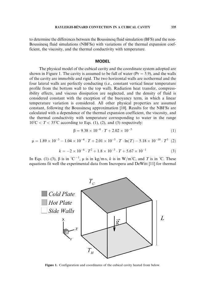
The physical model of the cubical cavity and the coordinate system adopted areshown in Figure 1. The cavity is assumed to be full of water (Pr ¼ 5.9), and the wallsof the cavity are immobile and rigid. The two horizontal walls are isothermal and thefour lateral walls are perfectly conducting (i.e., constant vertical linear temperatureprofile from the bottom wall to the top wall). Radiation heat transfer, compress-ibility effects, and viscous dissipation are neglected, and the density of fluid isconsidered constant with the exception of the buoyancy term, in which a lineartemperature variation is considered. All other physical properties are assumedconstant, following the Boussinesq approximation [10]. Results for the NBFSs arecalculated with a dependence of the thermal expansion coefficient, the viscosity, andthe thermal conductivity with temperature corresponding to water in the range10�C < T < 35�C according to Eqs. (1), (2), and (3) respectively:
b ¼ 9:38� 10�6 � T þ 2:02� 10�5 ð1Þ
m ¼ 1:89� 10�3 � 1:04� 10�4 � T þ 2:01� 10�5 � T � ln Tð Þ � 5:18� 10�10 � T3 ð2Þ
k ¼ �2� 10�6 � T2 þ 1:8� 10�3 � T þ 5:67� 10�1 ð3Þ
In Eqs. (1)–(3), b is in �C�1, m is in kg=ms, k is in W=m�C, and T is in �C. Theseequations fit well the experimental data from Incropera and DeWitt [11] for thermal
Figure 1. Configuration and coordinates of the cubical cavity heated from below.
RAYLEIGH-BENARD CONVECTION IN A CUBICAL CAVITY 335
expansion coefficient, from Potter and Wiggert [12] for viscosity, and from Holman[13] for thermal conductivity.
Gray and Giorgini [10] fixed the maximum temperature differences within thefluid to consider the Boussinesq approximation valid as those producing a variationof 10% of the physical properties. For water at T0 ¼ 26.0�C, the maximum tem-perature differences according to this criterion are DT� 2.9�C for the thermal expan-sion coefficient, DT� 4.5�C for the viscosity, and DT� 35.7�C for the thermalconductivity. In this study, the variation of viscosity and thermal conductivity withtemperature is first considered to determine the differences with the constant physi-cal properties simulation. The variation of the thermal expansion coefficient withtemperature is also considered to determine its individual effect on the flow and tem-perature fields, and finally, the combined effects of the variation of the three physicalproperties are studied and compared with the BFS.
The maximum variation of the physical properties of water for the temperatureincrement used in this study (DT ¼ 17.5�C ) are given in Table 1. It can be seen thatthe differences for the thermal expansion coefficient and viscosity are well abovethe 10% proposed by Gray and Giorgini [10]. Note that the temperature incrementis six times larger than the maximum suggested by these authors for the variation ofthermal expansion coefficient with temperature. The cubical cavity heights (L)are 0.0031, 0.0055, and 0.0313m for Ra ¼ 104, Ra ¼ 5� 104, and Ra ¼ 107,respectively.
The continuity equation, the momentum equations, and the thermal energyequation in terms of nondimensional variables and in Cartesian coordinates are
qu�iqx�i
¼ 0 ð4Þ
qu�iqt�
þqðu�j u�i Þqx�j
¼�qp�
qx�iþPr0
qqx�j
m�qu�iqx�j
þqu�j@x�i
!" #þRa0 Pr0ðT� þBT�2Þdi1 ð5Þ
and
qT�
qt�þ u�i
qT�
qx�i¼ qqx�i
k�qT�
qx�i
� �� �ð6Þ
respectively.In Eqs. (5) and (6), m� ¼ m(T )=m0, k� ¼ k(T )=k0, and B ¼ 9.38� 10�6DT=2b0
according to the fitting functions of Eqs. (1), (2), and (3). The reference scales forlength, velocity, time, and pressure are, respectively, L, a0=L, L
2=a0, and a02q0=L
2.
Table 1. Variation of physical properties of water for a temperature difference of
17.5�C between cold and hot plates in comparison to their values at the mean
temperature (T0 ¼ 26:0�C) ð%q ¼ ðqTH � qTCÞ100=qToÞ
%b %m %k %Cp %q
62.1 40.0 4.8 0.6 0.4
336 L. VALENCIA ET AL.
The nondimensional temperature is defined as T� ¼ (T� T0)=DT, whereDT ¼ (TH � TC) and T0 is the mean temperature T0 ¼ (THþTC)=2. All the physicalproperties in the Ra and Pr numbers are evaluated at T0. The six walls are assumedto be rigid and static (ui
� ¼ 0), and the thermal conditions at the hot and cold platesare TH ¼ 0.5 and TC ¼ �0.5, respectively. A linear temperature profile between hotplate and cold plate is imposed at the vertical walls (T� ¼ �x� þ 0.5). In calculationswith the Boussinesq approximation, m� ¼ k� ¼ 1.0 is used and the buoyancy termhas a linear dependence on temperature [i.e., B ¼ 0 in Eq. (5)]. Consequently, forBFS, Eqs. (5) and (6) become
qu�iqt�
þqðu�j u�i Þqx�j
¼ � qp�
qx�iþ Pr0
q2u�iqx�2j
þRa0 Pr0 T�di1 ð7Þ
qT�
qt�þ u�i
qT�
qx�i¼ q2T�
qx�2ið8Þ
The local and average Nusselt numbers at the hot and cold plates were com-puted with second-order accuracy and are defined as
Nu ¼ k�qT�
qx�
��������x�¼0 or 1
ð9Þ
and
Nus ¼ k�Z 1
0
Z 1
0
Nu dy�dz� ð10Þ
where k� ¼ 1 in the calculations with BFS and NBFSb. Equations (4), (5), and (6)and the corresponding boundary conditions have been solved numerically with thecontrol-volume code 3DINAMICS. In this second-order-accuracy code, the diffus-ive and convective fluxes are discretized in a staggered grid using a central scheme.The code performs the time-marching procedure with an explicit Adams-Bashforthscheme. The coupling between the pressure and the velocity field is computed using apredictor-corrector scheme involving a Poisson equation that is solved with the con-jugate gradient method. The details of the complete mathematical formulation andthe description of the numerical methods can be found in Cuesta [14]. Uniform gridsof 413 nodes have been used for the low Rayleigh number simulations (Ra ¼ 104 andRa ¼ 5� 104). Pallares et al. [4] showed that this grid resolution is adequate fordescribing these flows. They successfully compared numerical velocity distributionsof the different flow structures at Ra� 8� 104 and Pr ¼ 130 computed using thesame grid resolution with the corresponding experimentally measured distributions.At Ra ¼ 8� 104 and Pr ¼ 130 the difference in average Nusselt numbers using uni-form grids of 413 and 813 nodes was 2.5%. Consequently, the numerical simulationsat low Rayleigh numbers (Ra ¼ 104 and Ra ¼ 5� 104) were carried out withuniform grids of 413 and time steps of Dt� ¼ 5� 10�6.
RAYLEIGH-BENARD CONVECTION IN A CUBICAL CAVITY 337
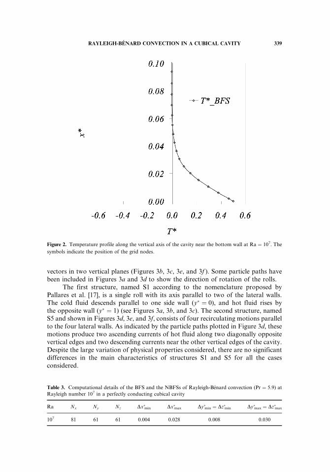
Numerical simulations at Ra ¼ 107 and Pr ¼ 5.9 were conducted with directnumerical simulation (DNS) with nonuniform grids of Nx ¼ 81, Ny ¼ 61, andNz ¼ 61 nodes and time steps of about Dt� ¼ 5� 10�7. According to the large-eddysimulation (LES) reported by Pallares et al. [5], at Ra ¼ 106, the use of time stepsof Dt� ¼ 1.2� 10�6, and nonuniform grids of 613 nodes produces averagedratios between the subgrid-scale viscosity and the molecular viscosity of only 0.5%.Grotzbach [15] deduced criteria to predict grid sizes for accurate direct numericalsimulations of Rayleigh-Benard turbulent flows. These criteria are based on wave-length considerations, boundary-layer-thickness estimates, and on a simplified theo-retical model to calculate the coefficient of a subgrid-scale heat flux model. The meangrid widths used in this work agree with the minimum corresponding to the criteriareported by Grotzbach [15] (see Table 2). The grid used at Ra ¼ 107 has at least 8grid nodes within the thermal boundary layers near the horizontal walls, as shownin Figure 2. Table 3 shows the computational details of the numerical simulationsat Ra ¼ 107.
RESULTS AND DISCUSSION
In this section the influences of the variation of thermal expansion coefficient,viscosity, and thermal conductivity with temperature are presented for the flowstructures at low (Ra ¼ 104 and Ra ¼ 5� 104) and high (Ra ¼ 107) Rayleigh num-bers for water at T0 ¼ 26.0�C (Pr ¼ 5.9).
Laminar Flow: Non-Boussinesq Effects at Low Rayleigh Numbers
We investigate the individual and the combined effects of the dependence of thephysical properties of the fluid on temperature, for two stable, steady, and laminarflow structures. The different cases analyzed are
1. Effects of viscosity and thermal conductivity variation with temperature(NBFSm).
2. Effects of thermal expansion coefficient variation with temperature(NBFSb).
3. Combined effects of viscosity, thermal conductivity, and thermal expansioncoefficient variation with temperature (NBFSmb).
The flow structures are depicted in Figure 3 in terms of isosurfaces of thesecond largest eigenvalue of the velocity gradient tensor (Figures 3a and 3d), follow-ing the method to detect the occurrence of vortex cores [16] and in terms of velocity
Table 2. Required mean grid widths (Dxyz�m ¼ (Dx�mDy�mDz�m)1=3) and horizontal number of nodes
(Ny ¼ Nz) according to the criteria deduced by Grotzbach [15] for turbulent flow at Ra ¼ 107 and Pr ¼ 5.9
Required Required Present Present Present Present
Ra Dxyz�m Ny ¼ Nz Dx�m Dy�m ¼ Dz�m Dxyz�m Ny ¼ Nz
107 0.0174 48 0.0126 0.0168 0.0152 61
338 L. VALENCIA ET AL.
vectors in two vertical planes (Figures 3b, 3c, 3e, and 3f ). Some particle paths havebeen included in Figures 3a and 3d to show the direction of rotation of the rolls.
The first structure, named S1 according to the nomenclature proposed byPallares et al. [17], is a single roll with its axis parallel to two of the lateral walls.The cold fluid descends parallel to one side wall (y� ¼ 0), and hot fluid rises bythe opposite wall (y� ¼ 1) (see Figures 3a, 3b, and 3c). The second structure, namedS5 and shown in Figures 3d, 3e, and 3f, consists of four recirculating motions parallelto the four lateral walls. As indicated by the particle paths plotted in Figure 3d, thesemotions produce two ascending currents of hot fluid along two diagonally oppositevertical edges and two descending currents near the other vertical edges of the cavity.Despite the large variation of physical properties considered, there are no significantdifferences in the main characteristics of structures S1 and S5 for all the casesconsidered.
Table 3. Computational details of the BFS and the NBFSs of Rayleigh-Benard convection (Pr ¼ 5.9) at
Rayleigh number 107 in a perfectly conducting cubical cavity
Ra Nx Ny Nz Dx�min Dx�max Dy�min ¼ Dz�min Dy�max ¼ Dz�max
107 81 61 61 0.004 0.028 0.008 0.030
Figure 2. Temperature profile along the vertical axis of the cavity near the bottom wall at Ra ¼ 107. The
symbols indicate the position of the grid nodes.
RAYLEIGH-BENARD CONVECTION IN A CUBICAL CAVITY 339
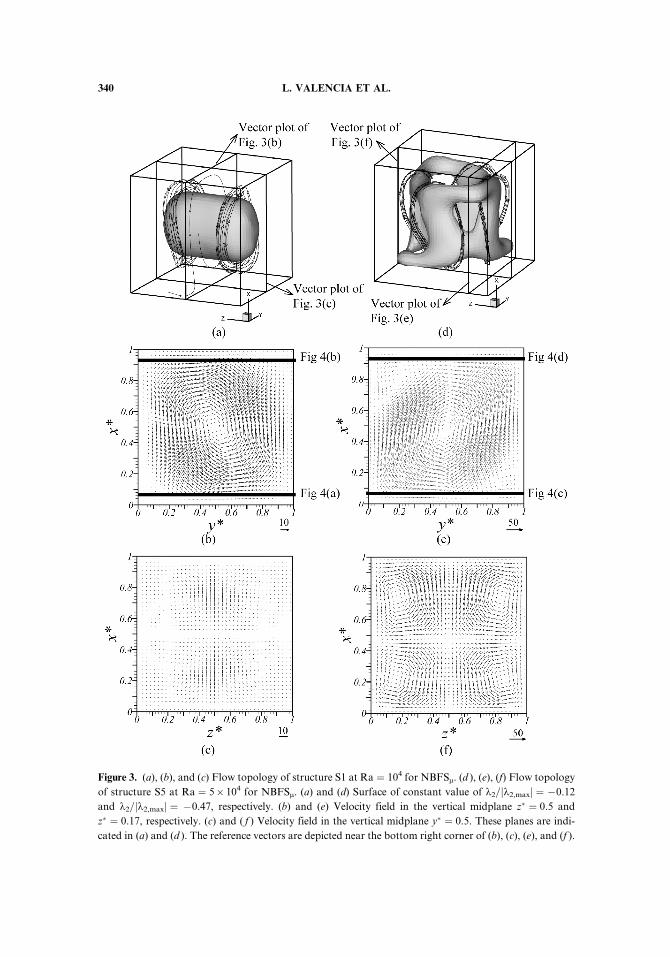
Figure 3. (a), (b), and (c) Flow topology of structure S1 at Ra ¼ 104 for NBFSm. (d ), (e), (f) Flow topology
of structure S5 at Ra ¼ 5� 104 for NBFSm. (a) and (d) Surface of constant value of k2=jk2,maxj ¼ �0.12
and k2=jk2,maxj ¼ �0.47, respectively. (b) and (e) Velocity field in the vertical midplane z� ¼ 0.5 and
z� ¼ 0.17, respectively. (c) and ( f ) Velocity field in the vertical midplane y� ¼ 0.5. These planes are indi-
cated in (a) and (d ). The reference vectors are depicted near the bottom right corner of (b), (c), (e), and (f ).
340 L. VALENCIA ET AL.
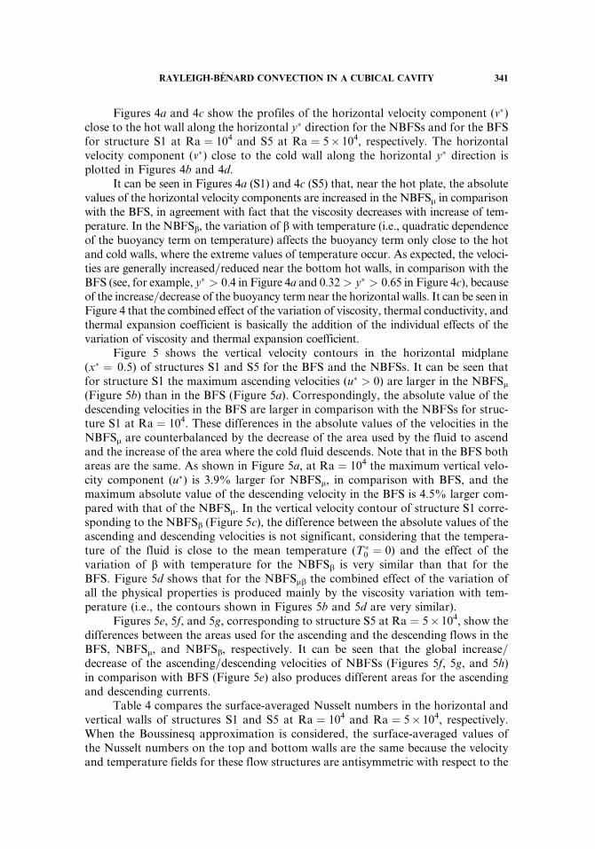
Figures 4a and 4c show the profiles of the horizontal velocity component (v�)close to the hot wall along the horizontal y� direction for the NBFSs and for the BFSfor structure S1 at Ra ¼ 104 and S5 at Ra ¼ 5� 104, respectively. The horizontalvelocity component (v�) close to the cold wall along the horizontal y� direction isplotted in Figures 4b and 4d.
It can be seen in Figures 4a (S1) and 4c (S5) that, near the hot plate, the absolutevalues of the horizontal velocity components are increased in the NBFSm in comparisonwith the BFS, in agreement with fact that the viscosity decreases with increase of tem-perature. In the NBFSb, the variation of b with temperature (i.e., quadratic dependenceof the buoyancy term on temperature) affects the buoyancy term only close to the hotand cold walls, where the extreme values of temperature occur. As expected, the veloci-ties are generally increased=reduced near the bottom hot walls, in comparison with theBFS (see, for example, y� > 0.4 in Figure 4a and 0.32 > y� > 0.65 in Figure 4c), becauseof the increase=decrease of the buoyancy term near the horizontal walls. It can be seen inFigure 4 that the combined effect of the variation of viscosity, thermal conductivity, andthermal expansion coefficient is basically the addition of the individual effects of thevariation of viscosity and thermal expansion coefficient.
Figure 5 shows the vertical velocity contours in the horizontal midplane(x� ¼ 0.5) of structures S1 and S5 for the BFS and the NBFSs. It can be seen thatfor structure S1 the maximum ascending velocities (u� > 0) are larger in the NBFSm(Figure 5b) than in the BFS (Figure 5a). Correspondingly, the absolute value of thedescending velocities in the BFS are larger in comparison with the NBFSs for struc-ture S1 at Ra ¼ 104. These differences in the absolute values of the velocities in theNBFSm are counterbalanced by the decrease of the area used by the fluid to ascendand the increase of the area where the cold fluid descends. Note that in the BFS bothareas are the same. As shown in Figure 5a, at Ra ¼ 104 the maximum vertical velo-city component (u�) is 3.9% larger for NBFSm, in comparison with BFS, and themaximum absolute value of the descending velocity in the BFS is 4.5% larger com-pared with that of the NBFSm. In the vertical velocity contour of structure S1 corre-sponding to the NBFSb (Figure 5c), the difference between the absolute values of theascending and descending velocities is not significant, considering that the tempera-ture of the fluid is close to the mean temperature (T�
0 ¼ 0) and the effect of thevariation of b with temperature for the NBFSb is very similar than that for theBFS. Figure 5d shows that for the NBFSmb the combined effect of the variation ofall the physical properties is produced mainly by the viscosity variation with tem-perature (i.e., the contours shown in Figures 5b and 5d are very similar).
Figures 5e, 5f, and 5g, corresponding to structure S5 at Ra ¼ 5� 104, show thedifferences between the areas used for the ascending and the descending flows in theBFS, NBFSm, and NBFSb, respectively. It can be seen that the global increase=decrease of the ascending=descending velocities of NBFSs (Figures 5f, 5g, and 5h)in comparison with BFS (Figure 5e) also produces different areas for the ascendingand descending currents.
Table 4 compares the surface-averaged Nusselt numbers in the horizontal andvertical walls of structures S1 and S5 at Ra ¼ 104 and Ra ¼ 5� 104, respectively.When the Boussinesq approximation is considered, the surface-averaged values ofthe Nusselt numbers on the top and bottom walls are the same because the velocityand temperature fields for these flow structures are antisymmetric with respect to the
RAYLEIGH-BENARD CONVECTION IN A CUBICAL CAVITY 341
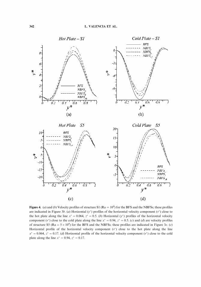
Figure 4. (a) and (b) Velocity profiles of structure S1 (Ra ¼ 104) for the BFS and the NBFSs; these profiles
are indicated in Figure 3b. (a) Horizontal (y�) profiles of the horizontal velocity component (v�) close to
the hot plate along the line x� ¼ 0.064, z� ¼ 0.5. (b) Horizontal (y�) profiles of the horizontal velocity
component (v�) close to the cold plate along the line x� ¼ 0.94, z� ¼ 0.5. (c) and (d) are velocity profiles
of structure S5 (Ra ¼ 5� 104) for the BFS and the NBFSs; these profiles are indicated in Figure 3e. (c)
Horizontal profile of the horizontal velocity component (v�) close to the hot plate along the line
x� ¼ 0.064, z� ¼ 0.17. (d) Horizontal profile of the horizontal velocity component (v�) close to the cold
plate along the line x� ¼ 0.94, z� ¼ 0.17.
342 L. VALENCIA ET AL.
Figure
5.Verticalvelocity
contours
(u� )
inthehorizontalmidplane(x
�¼
0.5)for(a)BFS,(b)NBFSm,(c)NBFSb,and(d)NBFSmbatRa¼
104,andfor(e)BFS,(f)
NBFSm,(g)NBFSb,and(h)NBFSmbatRa¼
5�104.Continuous=dashed
linecontours
correspondto
positive=negativevalues.
343
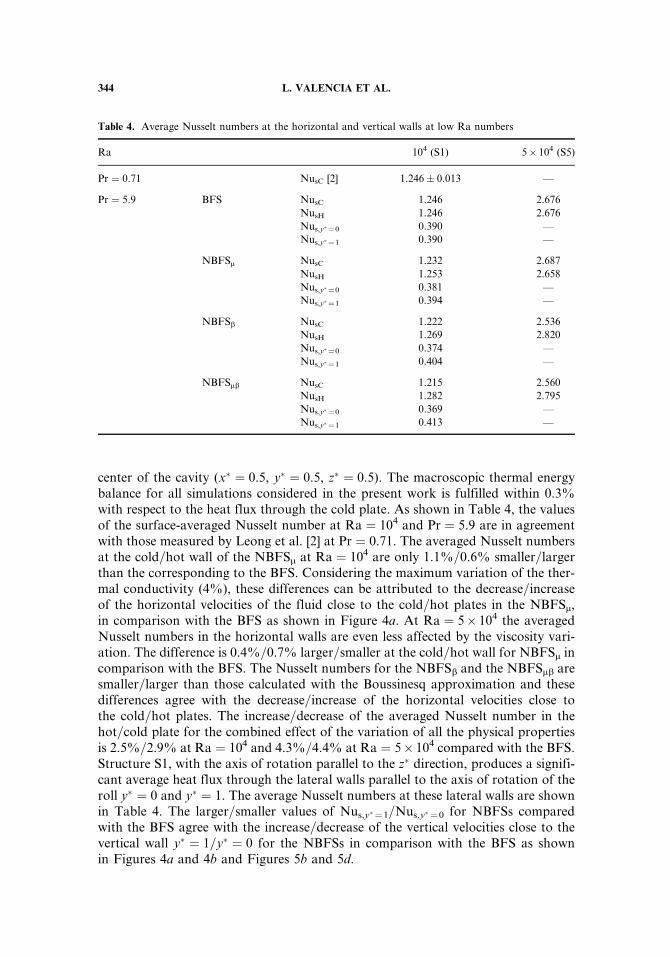
center of the cavity (x� ¼ 0.5, y� ¼ 0.5, z� ¼ 0.5). The macroscopic thermal energybalance for all simulations considered in the present work is fulfilled within 0.3%with respect to the heat flux through the cold plate. As shown in Table 4, the valuesof the surface-averaged Nusselt number at Ra ¼ 104 and Pr ¼ 5.9 are in agreementwith those measured by Leong et al. [2] at Pr ¼ 0.71. The averaged Nusselt numbersat the cold=hot wall of the NBFSm at Ra ¼ 104 are only 1.1%=0.6% smaller=largerthan the corresponding to the BFS. Considering the maximum variation of the ther-mal conductivity (4%), these differences can be attributed to the decrease=increaseof the horizontal velocities of the fluid close to the cold=hot plates in the NBFSm,in comparison with the BFS as shown in Figure 4a. At Ra ¼ 5� 104 the averagedNusselt numbers in the horizontal walls are even less affected by the viscosity vari-ation. The difference is 0.4%=0.7% larger=smaller at the cold=hot wall for NBFSm incomparison with the BFS. The Nusselt numbers for the NBFSb and the NBFSmb aresmaller=larger than those calculated with the Boussinesq approximation and thesedifferences agree with the decrease=increase of the horizontal velocities close tothe cold=hot plates. The increase=decrease of the averaged Nusselt number in thehot=cold plate for the combined effect of the variation of all the physical propertiesis 2.5%=2.9% at Ra ¼ 104 and 4.3%=4.4% at Ra ¼ 5� 104 compared with the BFS.Structure S1, with the axis of rotation parallel to the z� direction, produces a signifi-cant average heat flux through the lateral walls parallel to the axis of rotation of theroll y� ¼ 0 and y� ¼ 1. The average Nusselt numbers at these lateral walls are shownin Table 4. The larger=smaller values of Nus,y� ¼1=Nus,y� ¼0 for NBFSs comparedwith the BFS agree with the increase=decrease of the vertical velocities close to thevertical wall y� ¼ 1=y� ¼ 0 for the NBFSs in comparison with the BFS as shownin Figures 4a and 4b and Figures 5b and 5d.
Table 4. Average Nusselt numbers at the horizontal and vertical walls at low Ra numbers
Ra 104 (S1) 5� 104 (S5)
Pr ¼ 0.71 NusC [2] 1.246� 0.013 —
Pr ¼ 5.9 BFS NusC 1.246 2.676
NusH 1.246 2.676
Nus,y� ¼0 0.390 —
Nus,y� ¼1 0.390 —
NBFSm NusC 1.232 2.687
NusH 1.253 2.658
Nus,y� ¼0 0.381 —
Nus,y� ¼1 0.394 —
NBFSb NusC 1.222 2.536
NusH 1.269 2.820
Nus,y� ¼0 0.374 —
Nus,y� ¼1 0.404 —
NBFSmb NusC 1.215 2.560
NusH 1.282 2.795
Nus,y� ¼0 0.369 —
Nus,y� ¼1 0.413 —
344 L. VALENCIA ET AL.
Structures S1 and S5 do not produce any net heat flux on the lateral wallsperpendicular to the axis of their rolling motions in the case of constant physical pro-perties because the heat flux to the side wall generated by the ascending current isthe same as the heat flux from the wall caused by the descending current.
To determine the effects of viscosity, thermal conductivity, and thermal expan-sion coefficient variation with temperature on the mechanisms of the flow, we ana-lyzed the different terms of the vertical momentum equation for the three NBFSsand the BFS. The vertical momentum budget can be written as
0 ¼� 1
RaPr
qp�
qx�1þ 1
Ra
qqx�j
m�qu�1qx�j
þqu�jqx�1
!" #þ ðT� þ BT�2Þ � 1
RaPr
qðu�1u�j Þqx�j
ðPTÞ ðDTÞ ðBTÞ ðCTÞPressure Diffusive term Buoyancy Convective
gradient term term
term ð11Þ
Note that all terms of the x-momentum equation [Eq. (5)] have been displaced to theright-hand side and divided by RaPr to obtain Eq. (11).
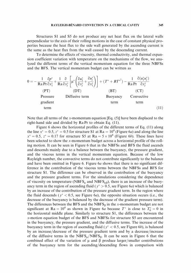
Figure 6 shows the horizontal profiles of the different terms of Eq. (11) alongthe line x� ¼ 0.5, z� ¼ 0.5 for structure S1 at Ra ¼ 104 (Figure 6a) and along the linex� ¼ 0.5, z� ¼ 0.17 for structure S5 at Ra ¼ 5� 104 (Figure 6b). These lines havebeen selected to show the x-momentum budget across a horizontal profile of the roll-ing motion. It can be seen in Figure 6 that in the NBFSs and BFS the fluid ascendsand descends mainly due to a balance between the buoyancy, the pressure gradient,and the viscous terms in the vertical momentum equation. Because of the lowRayleigh number, the convective terms do not contribute significantly to the balanceand have been omitted in Figure 6. Figure 6a shows that there is no significant dif-ference in the contribution of the viscous terms between the NBFSs and BFS forstructure S1. The difference can be observed in the contribution of the buoyancyand the pressure gradient terms. For the simulations considering the dependenceof viscosity on temperature (NBFSm and NBFSmb), there is an increase of the buoy-ancy term in the region of ascending fluid ( y� > 0.5, see Figure 6a) which is balancedby an increase of the contribution of the pressure gradient term. In the region wherethe fluid descends ( y� < 0.5, see Figure 6a), the opposite situation occurs (i.e., thedecrease of the buoyancy is balanced by the decrease of the gradient pressure term).The differences between the BFS and the NBFSb in the x-momentum budget are notsignificant at Ra ¼ 104 as shown in Figure 6a because T � is close to T�
0 ¼ 0 inthe horizontal middle plane. Similarly to structure S1, the differences between thex-motion equation budget of the BFS and NBFSs for structure S5 are encounteredin the buoyancy, the pressure gradient, and the diffusive terms. The increase of thebuoyancy term in the region of ascending fluid ( y� < 0.5, see Figure 6b), is balancedby an increase=decrease of the pressure gradient term and by a decrease=increaseof the diffusive terms in the NBFSm=NBFSb. It can be seen in Figure 6 that thecombined effect of the variation of m and b produce larger=smaller contributionsof the buoyancy term for the ascending=descending flows in comparison with
RAYLEIGH-BENARD CONVECTION IN A CUBICAL CAVITY 345
the Boussinesq simulation. In the region of descending fluid, the situation is theopposite to that in the ascending region.
BFS and NBFS of Turbulent Flow at Ra=107
The effect of the variation of m, b, and k with temperature on turbulentRayleigh-Benard flow is analyzed at Ra ¼ 107 using water as a convecting fluid atT0 ¼ 26.0�C (Pr ¼ 5.9). The NBFSs were performed with a temperature differencebetween the hot and cold plates of 17.5�C, which corresponds to a cavity height ofL ¼ 0.031m. This temperature increment produces a variation of b and m of 62%and 40%, respectively (see Table 1).
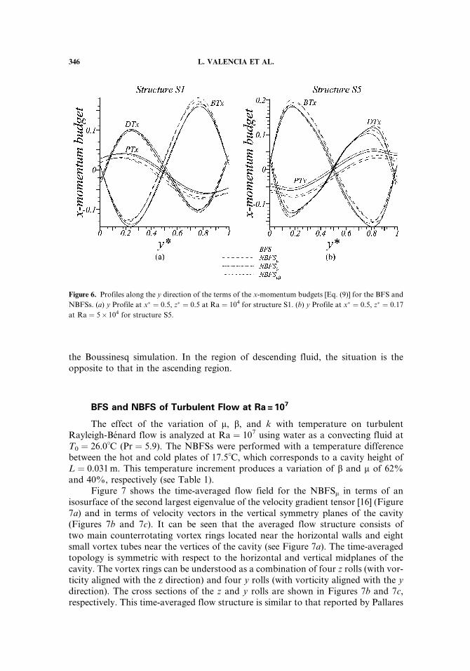
Figure 7 shows the time-averaged flow field for the NBFSm in terms of anisosurface of the second largest eigenvalue of the velocity gradient tensor [16] (Figure7a) and in terms of velocity vectors in the vertical symmetry planes of the cavity(Figures 7b and 7c). It can be seen that the averaged flow structure consists oftwo main counterrotating vortex rings located near the horizontal walls and eightsmall vortex tubes near the vertices of the cavity (see Figure 7a). The time-averagedtopology is symmetric with respect to the horizontal and vertical midplanes of thecavity. The vortex rings can be understood as a combination of four z rolls (with vor-ticity aligned with the z direction) and four y rolls (with vorticity aligned with the ydirection). The cross sections of the z and y rolls are shown in Figures 7b and 7c,respectively. This time-averaged flow structure is similar to that reported by Pallares
Figure 6. Profiles along the y direction of the terms of the x-momentum budgets [Eq. (9)] for the BFS and
NBFSs. (a) y Profile at x� ¼ 0.5, z� ¼ 0.5 at Ra ¼ 104 for structure S1. (b) y Profile at x� ¼ 0.5, z� ¼ 0.17
at Ra ¼ 5� 104 for structure S5.
346 L. VALENCIA ET AL.
et al. [5] at Ra ¼ 106 (Pr ¼ 0.71). The flow structure and velocity fields for the Bous-sinesq simulation and the other non-Boussinesq simulations (NBFSb and NBFSmb)are very similar to those shown in Figure 7 corresponding to NBFSm and conse-quently have been omitted.
The flow at Ra ¼ 107 presents large fluctuations in the velocity and tempera-ture fields with respect to the time-averaged values. Table 5 shows the values ofthe integral scale, the number of integral scales sampled (t�t =T �), and the time-averaged fluctuations of the surface-averaged Nusselt number on the cold plate(NuC) and u�, v�, and T� at the position x� ¼ 0.5, y� ¼ 0.75, and z� ¼ 0.5. The flowstatistics discussed in this section were obtained by sampling the statisticallydeveloped velocity and thermal fields during t�t ¼ 0:071 nondimensional time units.
Figure 7. Time-average flow fields at Ra ¼ 107 for the NBFSm. (a) Surface of constant value of
k2=jk2,maxj ¼ �0.017. (b) Velocity field in the vertical midplane z� ¼ 0.5 and (c) Velocity field in the
vertical midplane y� ¼ 0.5. These midplanes are indicated in (a). The reference vector is depicted near
the bottom right corner of (b) and (c).
RAYLEIGH-BENARD CONVECTION IN A CUBICAL CAVITY 347
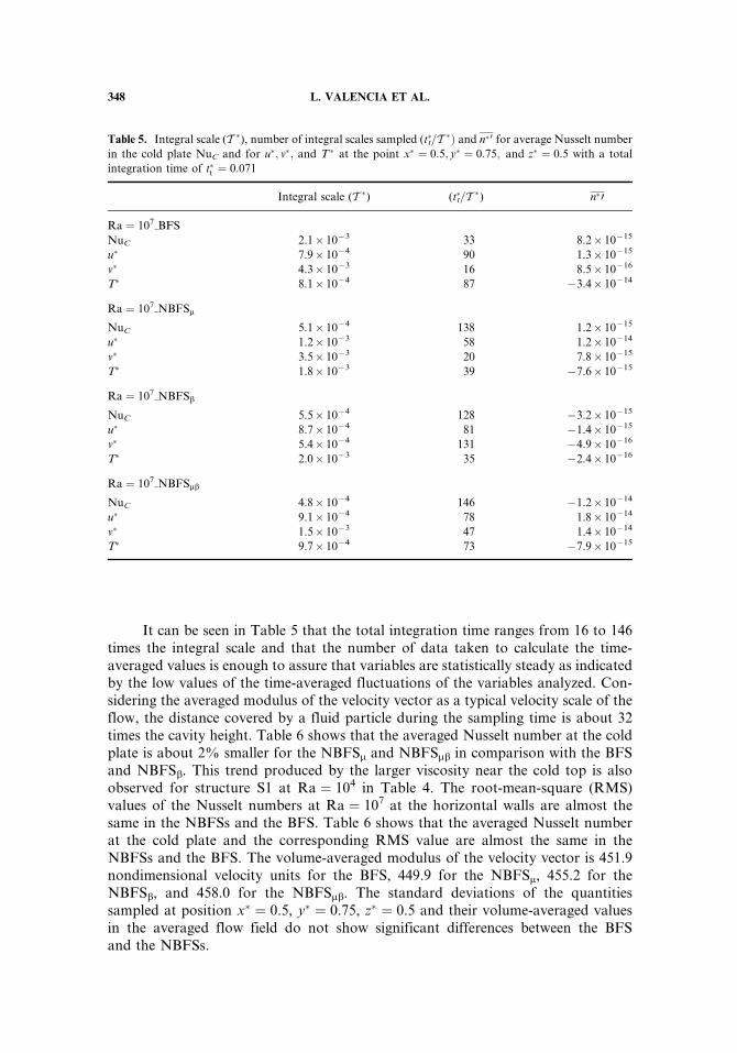
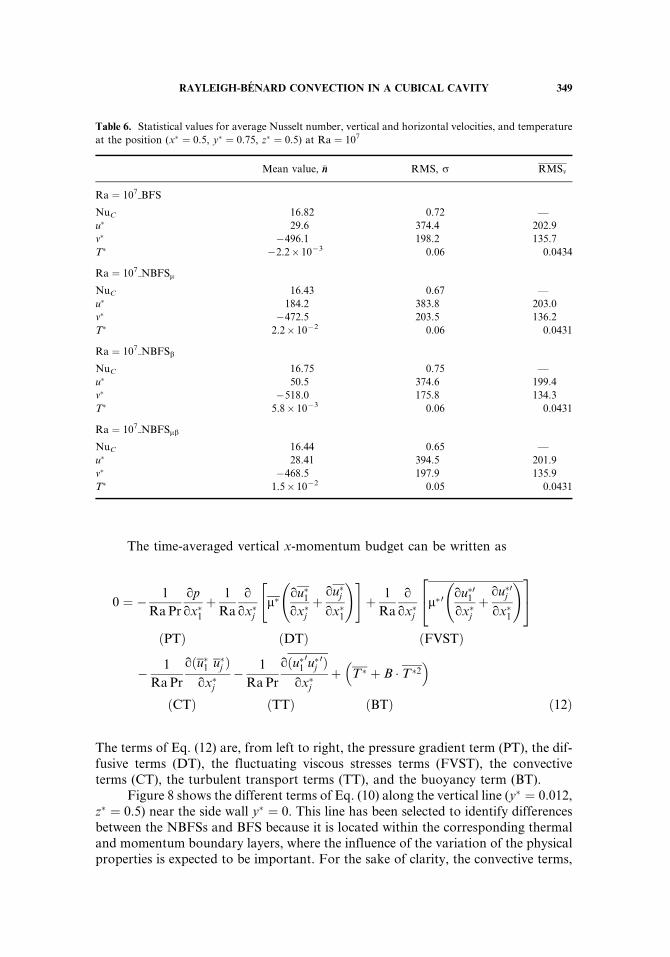
It can be seen in Table 5 that the total integration time ranges from 16 to 146times the integral scale and that the number of data taken to calculate the time-averaged values is enough to assure that variables are statistically steady as indicatedby the low values of the time-averaged fluctuations of the variables analyzed. Con-sidering the averaged modulus of the velocity vector as a typical velocity scale of theflow, the distance covered by a fluid particle during the sampling time is about 32times the cavity height. Table 6 shows that the averaged Nusselt number at the coldplate is about 2% smaller for the NBFSm and NBFSmb in comparison with the BFSand NBFSb. This trend produced by the larger viscosity near the cold top is alsoobserved for structure S1 at Ra ¼ 104 in Table 4. The root-mean-square (RMS)values of the Nusselt numbers at Ra ¼ 107 at the horizontal walls are almost thesame in the NBFSs and the BFS. Table 6 shows that the averaged Nusselt numberat the cold plate and the corresponding RMS value are almost the same in theNBFSs and the BFS. The volume-averaged modulus of the velocity vector is 451.9nondimensional velocity units for the BFS, 449.9 for the NBFSm, 455.2 for theNBFSb, and 458.0 for the NBFSmb. The standard deviations of the quantitiessampled at position x� ¼ 0.5, y� ¼ 0.75, z� ¼ 0.5 and their volume-averaged valuesin the averaged flow field do not show significant differences between the BFSand the NBFSs.
Table 5. Integral scale (T �), number of integral scales sampled (t�t=T �Þ and n�0 for average Nusselt number
in the cold plate NuC and for u�; v�; and T� at the point x� ¼ 0:5; y� ¼ 0:75; and z� ¼ 0:5 with a total
integration time of t�t ¼ 0:071
Integral scale (T �) (t�t=T �) n�0
Ra ¼ 107 BFS
NuC 2.1� 10�3 33 8.2� 10�15
u� 7.9� 10�4 90 1.3� 10�15
v� 4.3� 10�3 16 8.5� 10�16
T� 8.1� 10�4 87 �3.4� 10�14
Ra ¼ 107 NBFSm
NuC 5.1� 10�4 138 1.2� 10�15
u� 1.2� 10�3 58 1.2� 10�14
v� 3.5� 10�3 20 7.8� 10�15
T� 1.8� 10�3 39 �7.6� 10�15
Ra ¼ 107 NBFSb
NuC 5.5� 10�4 128 �3.2� 10�15
u� 8.7� 10�4 81 �1.4� 10�15
v� 5.4� 10�4 131 �4.9� 10�16
T� 2.0� 10�3 35 �2.4� 10�16
Ra ¼ 107 NBFSmb
NuC 4.8� 10�4 146 �1.2� 10�14
u� 9.1� 10�4 78 1.8� 10�14
v� 1.5� 10�3 47 1.4� 10�14
T� 9.7� 10�4 73 �7.9� 10�15
348 L. VALENCIA ET AL.
The time-averaged vertical x-momentum budget can be written as
0 ¼ � 1
RaPr
qpqx�1
þ 1
Ra
qqx�j
m�qu�1qx�j
þqu�jqx�1
!" #þ 1
Ra
qqx�j
m�0qu�01qx�j
þqu�0jqx�1
!24
35
ðPTÞ ðDTÞ ðFVSTÞ
� 1
RaPr
qðu�1 u�j Þqx�j
� 1
RaPr
qðu�10u�j
0Þqx�j
þ T� þ B � T�2� �
ðCTÞ ðTTÞ ðBTÞ ð12Þ
The terms of Eq. (12) are, from left to right, the pressure gradient term (PT), the dif-fusive terms (DT), the fluctuating viscous stresses terms (FVST), the convectiveterms (CT), the turbulent transport terms (TT), and the buoyancy term (BT).
Figure 8 shows the different terms of Eq. (10) along the vertical line (y� ¼ 0.012,z� ¼ 0.5) near the side wall y� ¼ 0. This line has been selected to identify differencesbetween the NBFSs and BFS because it is located within the corresponding thermaland momentum boundary layers, where the influence of the variation of the physicalproperties is expected to be important. For the sake of clarity, the convective terms,
Table 6. Statistical values for average Nusselt number, vertical and horizontal velocities, and temperature
at the position (x� ¼ 0.5, y� ¼ 0.75, z� ¼ 0.5) at Ra ¼ 107
Mean value, �nn RMS, r RMSv
Ra ¼ 107 BFS
NuC 16.82 0.72 —
u� 29.6 374.4 202.9
v� �496.1 198.2 135.7
T� �2.2� 10�3 0.06 0.0434
Ra ¼ 107 NBFSm
NuC 16.43 0.67 —
u� 184.2 383.8 203.0
v� �472.5 203.5 136.2
T� 2.2� 10�2 0.06 0.0431
Ra ¼ 107 NBFSb
NuC 16.75 0.75 —
u� 50.5 374.6 199.4
v� �518.0 175.8 134.3
T� 5.8� 10�3 0.06 0.0431
Ra ¼ 107 NBFSmb
NuC 16.44 0.65 —
u� 28.41 394.5 201.9
v� �468.5 197.9 135.9
T� 1.5� 10�2 0.05 0.0431
RAYLEIGH-BENARD CONVECTION IN A CUBICAL CAVITY 349
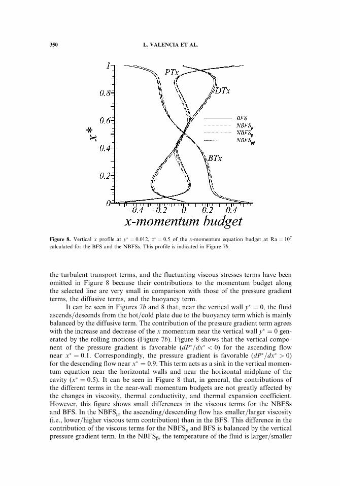
the turbulent transport terms, and the fluctuating viscous stresses terms have beenomitted in Figure 8 because their contributions to the momentum budget alongthe selected line are very small in comparison with those of the pressure gradientterms, the diffusive terms, and the buoyancy term.
It can be seen in Figures 7b and 8 that, near the vertical wall y� ¼ 0, the fluidascends=descends from the hot=cold plate due to the buoyancy term which is mainlybalanced by the diffusive term. The contribution of the pressure gradient term agreeswith the increase and decrease of the x momentum near the vertical wall y� ¼ 0 gen-erated by the rolling motions (Figure 7b). Figure 8 shows that the vertical compo-nent of the pressure gradient is favorable (dP�=dx� < 0) for the ascending flownear x� ¼ 0.1. Correspondingly, the pressure gradient is favorable (dP�=dx� > 0)for the descending flow near x� ¼ 0.9. This term acts as a sink in the vertical momen-tum equation near the horizontal walls and near the horizontal midplane of thecavity (x� ¼ 0.5). It can be seen in Figure 8 that, in general, the contributions ofthe different terms in the near-wall momentum budgets are not greatly affected bythe changes in viscosity, thermal conductivity, and thermal expansion coefficient.However, this figure shows small differences in the viscous terms for the NBFSsand BFS. In the NBFSm, the ascending=descending flow has smaller=larger viscosity(i.e., lower=higher viscous term contribution) than in the BFS. This difference in thecontribution of the viscous terms for the NBFSm and BFS is balanced by the verticalpressure gradient term. In the NBFSb, the temperature of the fluid is larger=smaller
Figure 8. Vertical x profile at y� ¼ 0.012, z� ¼ 0.5 of the x-momentum equation budget at Ra ¼ 107
calculated for the BFS and the NBFSs. This profile is indicated in Figure 7b.
350 L. VALENCIA ET AL.
in the lower=higher half of the cavity, and this produces a decrease=increase of thebuoyancy term in comparison with the Boussinesq simulation. These changes inthe buoyancy term are mainly counterbalanced by the corresponding changes ofthe diffusive term. In the NBFSmb, the changes of the buoyancy term in comparisonwith the BFS are similar to those obtained in the NBFSb. However, these changesare balanced by changes in the gradient pressure term as in the NBFSm. It can be seenin Figure 8 that the individual influence of the dependence of m and b on temperaturein the diffusive terms is cancelled when the variation of both physical properties isconsidered and the contributions of the diffusive terms of BFS and NBFSmb are verysimilar.
CONCLUSIONS
Laminar and turbulent Rayleigh-Benard convection of water (T0 ¼ 26.0�C,Pr ¼ 5.9) in a perfectly conducting cavity have been studied considering constantphysical properties, variable viscosity and thermal conductivity, variable thermalexpansion coefficient, and the combined influence of the simultaneous variation ontemperature of these three properties. We considered a temperature increment of17.5�C between the bottom hot wall and the top cold wall. This maximum tempera-ture difference produces variations of 62% in thermal expansion coefficient, 40% inthe viscosity, and variations of only 4.5% in the thermal conductivity of water, withrespect to the corresponding values at the reference temperature (T0 ¼ 26.0�C). Thevariation of the thermal expansion coefficient and viscosity is well above the limit of10% usually considered for the adoption of the Boussinesq approximation. At lowRayleigh numbers (Ra ¼ 104 and Ra ¼ 5� 104), the variation of viscosity and ther-mal expansion coefficient produce an increase=decrease of the maximum horizontalvelocity of about 5% near the hot=cold plate due to the decrease=increase ofviscosity with temperature and the increase=decrease of the buoyancy term in thex-momentum equation. When the variations of viscosity, thermal conductivity,and thermal expansion coefficient with temperature are considered, the averagedNusselt numbers on the cold=hot wall are about 3% (Ra ¼ 104) and 4.5%(Ra ¼ 5� 104) larger=smaller in comparison with the corresponding values obtainedwith constant physical properties. At Ra ¼ 107 the time-averaged properties of theturbulent flow are not significantly affected by the dependence on temperature ofthe physical properties analyzed. The volume-averaged modulus of the velocity isonly 1.3% greater in the NBFSmb than in the BFS. The maximum differences inthe averaged Nusselt numbers at the horizontal plates is 1% for the four simulationscarried out at this Rayleigh number. There are also no significant differences in thecontribution of the different terms of the momentum budget within the vertical ther-mal and momentum boundary layer, where the viscous terms are important and thusthe variation of viscosity with temperature is not negligible. It can be concluded that,for the flow conditions analyzed in this work, a variation of 62% of the thermalexpansion coefficient and 40% of the viscosity have very limited influence on theflow. Consequently, the limit of a variation of 10% in the physical properties forthe applicability of the Boussinesq approximation suggested by Gray and Giorgini[10] can be considered too restrictive, especially for turbulent flows in which the
RAYLEIGH-BENARD CONVECTION IN A CUBICAL CAVITY 351
temperature gradients, and thus the effects of the variation of the physical properties,are restricted to the thin thermal boundary layers.
REFERENCES
1. D. W. Pepper and K. G. T. Hollands, Summary of Benchmark Numerical Studies for3-D Natural Convection in an Air-Filled Enclosure, Numer. Heat Transfer A, vol. 42,pp. 1–11, 2002.
2. W. H. Leong, K. G. T. Hollands, and A. P. Brunger, Experimental Nusselt Numbers for aCubical-Cavity Benchmark Problem in Natural Convection, Int. J. Heat Mass Transfer,vol. 42, no. 11, pp. 1979–1989, 1999.
3. J. Pallares, F. X. Grau, and F. Giralt, Flow Transitions in Laminar Rayleigh-BenardConvection in a Cubical Cavity at Moderate Rayleigh Numbers, Int. J. Heat Mass Trans-fer, vol. 42, pp. 753–769, 1999.
4. J. Pallares, M. P. Arroyo, F. X. Grau, and F. Giralt, Experimental Laminar Rayleigh-Benard Convection in a Cubical Cavity at Moderate Rayleigh and Prandtl Numbers,Exp. Fluids, vol. 31, no. 2, pp. 208–218, 2001.
5. J. Pallares, I. Cuesta, and F. X. Grau, Laminar and Turbulent Rayleigh-Benard Convec-tion in a Perfectly Conducting Cubical Cavity, Int. J. Heat Fluid Flow, vol. 23, pp. 346–358, 2002.
6. M. Manga, D. Weeraratne, and S. J. S. Morris, Boundary-Layer Thickness and Instabil-ities in Benard Convection of a Liquid with a Temperature-Dependent Viscosity, Phys.Fluids, vol. 13, pp. 802–805, 2001.
7. R. A. Trompert and U. Hansen, On the Rayleigh Number Dependence of Convectionwith a Strongly Temperature-Dependent Viscosity, Phys. Fluids, vol. 10, pp. 351–360,1998.
8. L. N. Moresi and V. S. Solomatov, Numerical Investigation of 2D Convection withExtremely Large Viscosity Variations, Phys. Fluids, vol. 7, pp. 2154–2162, 1995.
9. V. S. Solomatov, Scaling of Temperature- and Stress-Dependent Viscosity Convection,Phys. Fluids, vol. 7, pp. 266–274, 1995.
10. D. D. Gray and A. Giorgini, The Validity of the Boussinesq Approximation for Liquidsand Gasses, Int. J. Heat Mass Transfer, vol. 19, pp. 545–551, 1976.
11. F. P. Incropera and D. P. DeWitt, Fundamentals of Heat and Mass Transfer, 4th ed.,pp. 846–847, Wiley, New York, 1996.
12. M. C. Potter and D. C. Wiggert, Mec�aanica de Fluidos, 2d ed., pp. 754–755, Prentice Hall,Mexico, 1998.
13. J. P. Holman, Heat Transfer, 4th ed., p. 503, McGraw-Hill Kogakusha, Tokyo, 1976.14. I. Cuesta, Estudi Numeric de Fluxos Laminars i Turbulents en una Cavitat Cubica, Ph.D.
thesis, Universitat Rovira i Virgili, Tarragona, Spain, pp. 40–64, 1993.15. G. Grotzbach, Spatial Resolution Requirements for Direct Numerical Simulation of the
Rayleigh-Benard Convection, J. Comput. Phys., vol. 49, pp. 241–264, 1983.16. J. Jeong and F. Hussain, On the Identification of a Vortex, J. Fluid Mech, vol. 285,
pp. 69–80, 1995.17. J. Pallares, I. Cuesta, F. X. Grau, and F. Giralt, Natural Convection in a Cubical Cavity
Heated from Below at Low Rayleigh Numbers, Int. J. Heat Mass Transfer, vol. 39,pp. 3233–3247, 1996.
352 L. VALENCIA ET AL.
Related Documents