Pergamon Inf J. Heat Moss Transfer. Vol. 39, No. 15. pp. 3233-3247. 1996 Copyright ‘II 1996 Elsevier Science Ltd Prmted m Great Britam. All rights reserved 0017 9310/96$15.00+0.00 0017-9310(95)00390-8 Natural convection in a cubical cavity heated from below at low Rayleigh numbers J. PALLARES, I. CUESTA,? F. X. GRAU and FRANCESC GIRALT* Departament d’Enginyeria Electrica i Mecanica, *Departament d’Enginyeria Quimica. Escola Tecnica Superior d’Enginyeria Quimica, Universitat Rovira i Virgili, Ctra. Salou s/n, 43006 Tarragona. Spain (Received 17 May 1995 and infinalform 15 September 1995) Abstract-Natural convection in a cubical cavity heated from below is examined by means of the three- dimensional computation of the time dependent Navier-Stokes and energy transport equations in the range of Rayleigh numbers 3500 $ Ra < 10000. The Boussinesq approximation has been used to model buoyancy effects on momentum transfer. Four different stable convective structures occur with orientation and flow circulation dictated by the combined effect of the four adiabatic confining lateral walls. Three of these structures are typical single rolls with their axis of rotation or vorticity horizontal and either parallel to two opposite vertical walls, structures Sl and S3, or orientated towards two opposite vertical edges (S2). The fourth structure (S4) is a nearly toroidal roll with the descending motion aligned with the four vertical edges and the single ascending current along the vertical axis of the enclosure. The effect of the Rayleigh number and the type of flow structure on heat transfer rates at the top and bottom plates is also reported. For the single roll-type structures the surface averaged Nusselt number increases with a power of the Rayleigh number that changes within the range studied from 0.7 to 0.4. A similar trend is observed for the toroidal roll but in this case heat transfer rates are 65% lower. The distribution of local heat transfer coefficients at the top and bottom surfaces agrees with the topology of the flow patterns portrayed with the aid of the second invariant of the velocity gradient and the modulus of the cross product of the corresponding velocity and vorticity fields. Copyright 0 1996 Elsevier Science Ltd. INTRODUCTION Natural convection is a fundamental mechanism for momentum, heat and mass transfer in some natural phenomena and of interest in engineering systems. Independently from its geophysical, meteorological, astrophysical and engineering applications, natural convection in enclosures heated from below has been the topic of numerous theoretical and experimental studies because of its geometric simplicity and fun- damental implications. Among all possible con- figurations, the cubical cavity offers the additional interest of not having any preferred direction other than the direction of gravity. This characteristic enables the occurrence of different complex flow struc- tures under steady-state conditions for a given set of Rayleigh and Prandtl numbers. Furthermore, each structure affects the transfer of heat from the hot to the cold plate differently and the average Nusselt number becomes a function of the Rayleigh and Prandtl numbers and of the type of structure present. The Rayleigh-BCnard convection (RB) problem [l] in cavities has been extensively studied theoretically, experimentally and numerically since the beginning of the present century [2, 31. Koschmieder [4], Normand et al. [5], Oertel [6], Ostrach [7] and Yang [8] defined and described the main characteristics of the flow in t Author to whom correspondence should be addressed. heated enclosures. Flow stability is mainly affected by fluid properties, enclosure geometry and the external field. It is well known that there is a critical Rayleigh number (Ra,) for RB convection beyond which a buoyancy-driven flow develops with a corresponding increase in transfer rates. In the cubical cavity with lateral adiabatic walls the critical Rayleigh number is 3446 [9]. This theoretical value agrees with the exper- imental work of Heitz and Westwater [IO]. On the other hand, RB convection in a cubical cavity with perfectly conducting lateral walls presents a critical Rayleigh number of 7000 [ 11, 121. Concerning the topology of the flow. Ozoe et nf. [ 131 obtained two convective structures in the supercritical region 4000 < Ra < 8000 for the cubical cavity with adiabatic lateral walls. Both patterns may be described as single circulating rolls, one with axis parallel to two opposite vertical walls and the other with axis parallel to the diagonal of the horizontal walls. Recently Her- nandez and Frederick [14] found numerically a new convective structure at Ru = 8000 which exhibits a characteristic toroidal like form, with flow descending near the four vertical edges and ascending at the cen- tral vertical axis of the cube. The purpose of this study is to characterize numeri- cally the natural convection in a cubical cavity where buoyancy has been induced by imposing a moderate temperature difference between the bottom (hot) and the top (cold) plates with perfectly adiabatic vertical 3233

Welcome message from author
This document is posted to help you gain knowledge. Please leave a comment to let me know what you think about it! Share it to your friends and learn new things together.
Transcript

Pergamon
Inf J. Heat Moss Transfer. Vol. 39, No. 15. pp. 3233-3247. 1996 Copyright ‘II 1996 Elsevier Science Ltd
Prmted m Great Britam. All rights reserved 0017 9310/96$15.00+0.00
0017-9310(95)00390-8
Natural convection in a cubical cavity heated from below at low Rayleigh numbers
J. PALLARES, I. CUESTA,? F. X. GRAU and FRANCESC GIRALT* Departament d’Enginyeria Electrica i Mecanica, *Departament d’Enginyeria Quimica.
Escola Tecnica Superior d’Enginyeria Quimica, Universitat Rovira i Virgili, Ctra. Salou s/n, 43006 Tarragona. Spain
(Received 17 May 1995 and infinalform 15 September 1995)
Abstract-Natural convection in a cubical cavity heated from below is examined by means of the three- dimensional computation of the time dependent Navier-Stokes and energy transport equations in the range of Rayleigh numbers 3500 $ Ra < 10000. The Boussinesq approximation has been used to model buoyancy effects on momentum transfer. Four different stable convective structures occur with orientation and flow circulation dictated by the combined effect of the four adiabatic confining lateral walls. Three of these structures are typical single rolls with their axis of rotation or vorticity horizontal and either parallel to two opposite vertical walls, structures Sl and S3, or orientated towards two opposite vertical edges (S2). The fourth structure (S4) is a nearly toroidal roll with the descending motion aligned with the four vertical edges and the single ascending current along the vertical axis of the enclosure. The effect of the Rayleigh number and the type of flow structure on heat transfer rates at the top and bottom plates is also reported. For the single roll-type structures the surface averaged Nusselt number increases with a power of the Rayleigh number that changes within the range studied from 0.7 to 0.4. A similar trend is observed for the toroidal roll but in this case heat transfer rates are 65% lower. The distribution of local heat transfer coefficients at the top and bottom surfaces agrees with the topology of the flow patterns portrayed with the aid of the second invariant of the velocity gradient and the modulus of the cross product of the
corresponding velocity and vorticity fields. Copyright 0 1996 Elsevier Science Ltd.
INTRODUCTION
Natural convection is a fundamental mechanism for momentum, heat and mass transfer in some natural phenomena and of interest in engineering systems. Independently from its geophysical, meteorological, astrophysical and engineering applications, natural convection in enclosures heated from below has been the topic of numerous theoretical and experimental studies because of its geometric simplicity and fun- damental implications. Among all possible con- figurations, the cubical cavity offers the additional interest of not having any preferred direction other than the direction of gravity. This characteristic enables the occurrence of different complex flow struc- tures under steady-state conditions for a given set of Rayleigh and Prandtl numbers. Furthermore, each structure affects the transfer of heat from the hot to the cold plate differently and the average Nusselt number becomes a function of the Rayleigh and Prandtl numbers and of the type of structure present.
The Rayleigh-BCnard convection (RB) problem [l] in cavities has been extensively studied theoretically, experimentally and numerically since the beginning of the present century [2, 31. Koschmieder [4], Normand et al. [5], Oertel [6], Ostrach [7] and Yang [8] defined and described the main characteristics of the flow in
t Author to whom correspondence should be addressed.
heated enclosures. Flow stability is mainly affected by fluid properties, enclosure geometry and the external field. It is well known that there is a critical Rayleigh number (Ra,) for RB convection beyond which a buoyancy-driven flow develops with a corresponding increase in transfer rates. In the cubical cavity with lateral adiabatic walls the critical Rayleigh number is 3446 [9]. This theoretical value agrees with the exper- imental work of Heitz and Westwater [IO]. On the other hand, RB convection in a cubical cavity with perfectly conducting lateral walls presents a critical Rayleigh number of 7000 [ 11, 121.
Concerning the topology of the flow. Ozoe et nf. [ 131 obtained two convective structures in the supercritical region 4000 < Ra < 8000 for the cubical cavity with adiabatic lateral walls. Both patterns may be described as single circulating rolls, one with axis parallel to two opposite vertical walls and the other with axis parallel to the diagonal of the horizontal walls. Recently Her- nandez and Frederick [14] found numerically a new convective structure at Ru = 8000 which exhibits a characteristic toroidal like form, with flow descending near the four vertical edges and ascending at the cen- tral vertical axis of the cube.
The purpose of this study is to characterize numeri- cally the natural convection in a cubical cavity where buoyancy has been induced by imposing a moderate temperature difference between the bottom (hot) and the top (cold) plates with perfectly adiabatic vertical
3233
3234 .I. PALLARt% rt ~1.
NOMENCLATURE
.Y gravitational acceleration [m s ‘1 Greek letters H /H x W( [m s ‘1 thermal diffusivity [m’ s’] L reference length [m] i; thermal expansion coefficient [K -‘I I1 normal dimensionless coordinate o,, Kronecker delta N number of grid nodes in one direction I kinematic viscosity [m’ s ‘1 Nu Nusselt number. hL/k n second invariant of the velocity P pressure [Pa] gradient tensor [s-‘1 Pf Prandtl number, ~11~ vorticity vector [s ‘1 Rll Rayleigh number. g/IATL”,:vct ;I; rotation tensor, !2,,!2,, = - 0’/2 [s ‘1 RUC critical Rayleigh number A” increment.
S!, strain tensor [s’] T temperature [K] Superscripts and subscripts u velocity vector [m s ‘1 s surface averaged quantity II. I‘, II. velocity components * dimensionless quantity
Ims ‘I c cold wall .I-. J‘, z Cartesian coordinates h hot wall
b-4. 0 average quantity.
walls. The occurrence and topology of the different types of stable convective structures are examined within the interval 3500 ,< Ra < 10000 and their effect in heat transfer rates at the top and bottom plates is characterized. Flow and heat transfer for the two roll-typed structures previously described by Ozoe rf cl/. [ 131 with a coarser grid, hereinafter referred to as Sl and S2. are determined. The occurrence of an additional new roll-type structure (S3) with different topological and heat transport features is also reported. Finally. the flow and heat transfer charac- teristics of the toroidal roll (S4) described by Her- nandez and Frederick [14] at Ra = 8000 and a 21’ grid. is determined at Ra = 9000 and 10 000 using a finer 41’ grid.
GOVERNING EQUATIONS
The geometry of the cubical cavity and the coor- dinate system is shown in Fig. 1. Both the bottom and the top plates are taken to be isothermal with the lower one held at temperature Tn which is moderately greater than the temperature of the upper wall Tc, The four vertical walls are perfectly insulated.
The fluid considered in this study is air (Pr = 0.7 I ). Compressibility effects. viscous dissipation and the
??Cold plate
0 Adiabatic walls
??Hot Plate
Fig. I. Physical model of the cubical cavity heated from below.
variation of fluid properties with temperature have been neglected, with the only exception of the buoy- ancy term, for which the Boussinesq approximation has been adopted. As a result, the Navier-Stokes and the energy transport equations are coupled only by the body force term, where linear dependence of den- sity with temperature is assumed. According to Gray and Giorgini [ 151. the Boussinesq approximation for air at mean temperature T, = 15°C and P = 1 atm. holds for temperature differences up to 18.6 C when the two horizontal walls are 1 m apart.
The reference scales for length. velocity, time and pressure are, respectively, L, a/L. L’/sl and pd/L’. The non-dimensional temperature is defined as
T* _ -T-T, _ T- (TH + 7-c)/2 AT TH - T, (1)
while all other variables are converted into dimen- sionless form using the above scales. The non-dimen- sional governing transport equations in Cartesian coordinates are,
c;u* -CO ?.I?
for continuity.
(2)
?u,* + d(u,$,?y l?p* pu*
i-t* - p=-G+Pr
2X* I &* + RaPrT*b
I I
(3)
for momentum and
?T’ c:(u;T*) (7’T* (7r*+ (7.q = ~ (7u*.x* ‘i I
for energy.
(4)

Natural convection in a cubical cavity 3235
NUMERICAL METHOD
Numerical scheme The CFD code 3DINAMICS [ 16, 171 was used to
obtain numerical solutions of the above governing equations with second order accuracy and in terms of the primitive variables. In this code equations (2)-(4) are discretized following a control volume scheme [ 181 with non-uniform three-dimensional staggered grids. All computational grids used in the present study were regular. The convective fluxes across the surfaces of the control volumes were discretized using a second order QUICK scheme [19]. 3DINAMICS incor- porates the non-uniform grid version of QUICK pro- posed by Perng and Street [20] to enhance conver- gence. Second order approximations were also implemented for the diffusive fluxes with a centered scheme. The SMAC algorithm [21] was applied to compute the pressure field. This algorithm is based on a typical predictorcorrector scheme and leads to a fractional step method for the velocity-pressure coupling.
A critical step in the pressure algorithm, that affects the global performance of the code, is the solution of the Poisson equation. According to Koshla and Rubin [22] a much faster solution of Poisson-like equations is obtained with the Conjugate Gradient Method than with other methods. This methodology has been adopted in the present study. Convergence was increased by using the diagonal scaling technique to precondition the coefficient matrix. A semi-implicit, second order accurate, AD1 method [23] was applied for time-marching integration.
Heat transfer rates at the top and bottom walls is characterized with local and surface averaged Nusselt numbers defined, respectively, by
aT* N” = az* _.=Qor, I I
and
1 1
Nus = ss NM d-u* dy* 0 0
(6)
Equations (5) and (6) were solved using second order finite differences and interpolation schemes.
The boundary conditions for the dynamic field are u, = 0 at the walls, i.e., all six walls of the cavity are assumed to be rigid and at rest. The thermal boundary conditions are (aT/&) = 0 at the four adiabatic ver- tical walls, TR = 0.5 at bottom plate and Tr = -0.5 at the top plate.
Even though the RB problem with air in a cubical enclosure at Rayleigh numbers below 10 000 has only steady solutions, the numerical simulations using 3DINAMICS provide a complete description of the time-evolution towards steady-state conditions.
As initial conditions, the fluid was assumed to be at rest and a conductive temperature distribution was established in the whole domain. In order to enhance
the RB convective regime, a random disturbance in the temperature field with an amplitude of f0.05 (10% of the local temperature) was added to this initial thermal field [24]. This strategy avoids the pre- determination of the final convective structure. All four structures described in this work have been obtained starting all computations from this unbiased initial condition at different Rayleigh numbers. The use of other initial conditions, such as a non-uniform heating or cooling at the bottom or top plates, respec- tively, or a non-adiabatic condition at any of the four lateral walls during a short computational time, could favour the development of any of the aforementioned four structures, as well as that of other convective motions not reported in the present study for the range of Rayleigh numbers covered. Results obtained at a given Rayleigh number were successively used as initial conditions for computations at higher or lower Rayleigh numbers, to check the stability of the structures.
Validation Cuesta [ 161 and Cuesta et al. [I 71 validated
3DlNAMICS describing the flow in a cubical cavity driven either by the upper moving lid or the sim- ultaneous heating and cooling of two opposite vertical walls. Among these computations, the natural con- vection results are of special relevance to the present work. As it can be seen in Table 1, heat transfer rates predicted by Cuesta et al. [17] for two lateral and opposite walls in the range lo3 < Ra < lo6 are in good agreement with numerical predictions reported else- where [25-281.
The performance of 3DINAMICS in the RB prob- lem is established by comparing predictions with other numerical results and experimental data, and by ver- ifying the grid-independence of the present results. First, present results are consistent with previous com- putations, namely those of Ozoe et al. [13] and Her- nandez and Frederick [14]. Table 2 shows predicted Nusselt numbers for the structures Sl and S4 at different values of the Rayleigh number. It should be noted that Ozoe et al. [13] reported two different structures of the flow, Sl and S2, but only provided heat transfer rates for structure Sl. There is good agreement between present and previous predictions with discrepancies being caused by differences in grid size and Prandtl number.
The grid independence study was carried out at Ra = 10000. Starting with the coarsest grid of 213 control volumes, the grids were successively refined to 31”, 413 and 513 with uniformly distributed nodes. Figure 2 shows the evolution of the predicted surface averaged Nusselt number with the inverse of the num- ber of grid points for the three single roll-typed struc- tures Sl-S3 reported in this study. Structure S4 can only be obtained at Ra 10 000 with the finest grids of 41’ and 513 nodes. It should be noted that at this Rayleigh number this structure is close to a new tran- sition and the influence of the boundary layer at the

3236 J. PALLARES c/ (11.
Table 1. Comparison between several surface averaged Nusselt numbers reported in the literature for the side-heated cubical cavity
Ra Cuesta [ 161 Fusegi rt al. [25] Haldenwang [26] B. Mabrouk [27] David-Jones [28]
3D 3D 3D 3D 2D
IO’ 1.052 1.085 1.073 1.118 10J 2.187 2.1 2.083 2.243 IO5 4.512 4.361 4.31 4.452 4.519 IO” 8.846 x.77 X.61 9.215 8.8
Table 2. Comparison between several surface averaged Nusselt numbers reported in the literature for the cubical cavity heated from below
Author
Ozoe er u/. [13]
Hernandez and Frederick [ 141
RU
4000 6000 8000
x000
N% PI Structure Nns present work
I Sl 1.165 (9’) 1.164 (41’) I SI 1.535 (9’) 1.522 (41’) I Sl 1.746 (9’) 1.755 (413)
0.71 SJ 1.1 (3ll) 1.04 (41’) I .06 (212)
1.85
N”s
1.80
1.75
1.70 0.0 0.2 0.4 0.6 0.8 1.0 1.2
104/N3 Fig. 2. Surface averaged Nusselt number for the convecttve structures Sl. S2 and S3 at Ra = 10000 for different grid
densities.
lateral walls can only be captured with these finest grids. According to Fig. 2, increasing the nodes from 4 1’ to 5 I 3 does not represent more than 0.3 % variation in terms of the surface averaged Nusselt number. A similar discrepancy has been obtained for S4. Accord- ing to these results. the regular mesh of 4 I 3 points was used in all the computations.
To our knowledge. only numerical results are avail- able in the literature for cubical cavities. In order to
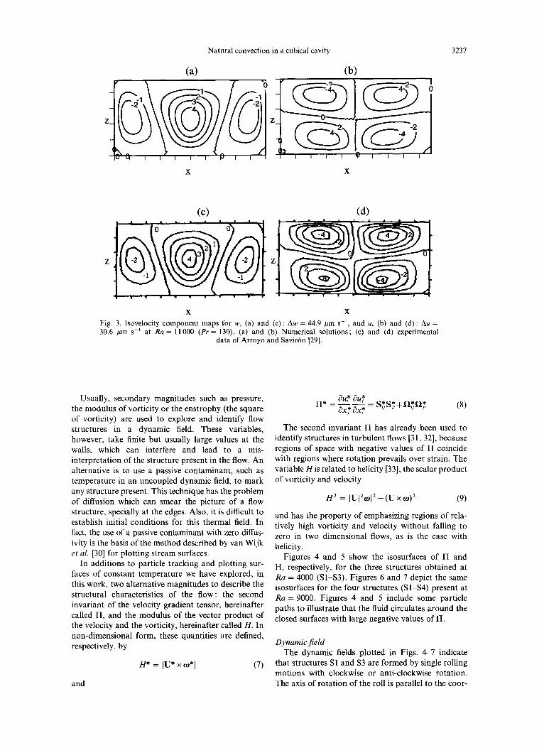
check 3DINAMICS with experimental results, those obtained by Arroyo and Saviron [29] for Rayleigh number 11000 and Prandtl number 130, at an average temperature of 25°C. have been selected. The physical dimensions of the cavity used by Arroyo and Saviron [29] are L.Y = 25 mm, L,v = 14.6 mm and LZ = 12.3 mm, with silicon oil (Pr = 130) as working fluid. Fig- ure 3 shows the comparison between these data and present predictions. in terms of isoline of either con- stant u-velocity or constant n,-velocity. at the central (J = constant) plane, where r-velocity equals zero. The numerical results obtained with a regular grid of 41 x 21 x 2 1 nodes are in good agreement qualitatively and quantitatively with the experimental data. Note that this grid is coarser in the .Y and z directions than the 41’ used in the present calculations for the cubical cavity.
RESULTS AND DISCUSSION
The visualization of three-dimensional (3D) dynamic fields is still a challenge in CFD. mainly because of their vectorial character. The objective of such visualization is to portray an image of the flow structure. The most common approach is to plot vec- tor fields or, similarly, fields of streamlines, pathlines or streaklines, all coincident in steady-state regimes, The definition of stream surfaces is somehow ambigu- ous because there are infinite ways of connecting streamlines. Despite this fact, this technique is one of the most suitable ways to ‘freeze’ a 3D flow field [30].
Natural convection in a cubical cavity 3231
(a> (b)
X X
Fig. 3. Isovelocity component maps for w, (a) and (c): Aw = 44.9 pm SC’, and U, (b) and (d): Au = 30.6 pm SK’ at Ra = 11000 (Pr = 130). (a) and (b) Numerical solutions; (c) and (d) experimental
data of Arroyo and Saviron [29].
Usually, secondary magnitudes such as pressure, the modulus of vorticity or the enstrophy (the square of vorticity) are used to explore and identify flow structures in a dynamic field. These variables, however, take finite but usually large values at the walls, which can interfere and lead to a mis- interpretation of the structure present in the flow. An alternative is to use a passive contaminant, such as temperature in an uncoupled dynamic field. to mark any structure present. This technique has the problem of diffusion which can smear the picture of a flow structure, specially at the edges. Also, it is difficult to establish initial conditions for this thermal field. In fact, the use of a passive contaminant with zero diffus- ivity is the basis of the method described by van Wijk et al. [30] for plotting stream surfaces.
au* au* n* = 22 = S?$?+Q?fi* ax: ax* I, I, 1, I, (8)
The second invariant II has already been used to identify structures in turbulent flows [31, 321, because regions of space with negative values of II coincide with regions where rotation prevails over strain. The variable His related to helicity [33], the scalar product of vorticity and velocity
(9)
and has the property of emphasizing regions of rela- tively high vorticity and velocity without falling to zero in two dimensional flows, as is the case with helicity.
In additions to particle tracking and plotting sur- faces of constant temperature we have explored, in this work, two alternative magnitudes to describe the structural characteristics of the flow: the second invariant of the velocity gradient tensor, hereinafter called II, and the modulus of the vector product of the velocity and the vorticity, hereinafter called H. In non-dimensional form, these quantities are defined, respectively, by
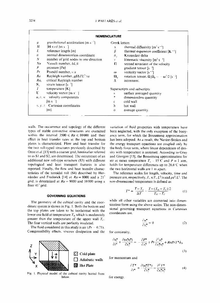
Figures 4 and 5 show the isosurfaces of II and H, respectively, for the three structures obtained at Ra = 4000 (Sl-S3). Figures 6 and 7 depict the same isosurfaces for the four structures (Sl-S4) present at Ra = 9000. Figures 4 and 5 include some particle paths to illustrate that the fluid circulates around the closed surfaces with large negative values of IT.
Dynamic field
H* = ]U* xw*I (7)
The dynamic fields plotted in Figs. 47 indicate that structures Sl and S3 are formed by single rolling motions with clockwise or anti-clockwise rotation. The axis of rotation of the roll is parallel to the coor- and
3238 J. PALLARkS e/ ul
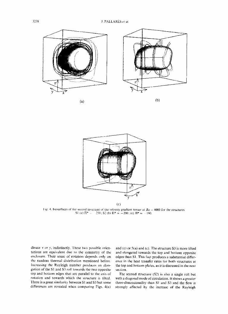
(cl Fig. 4. Isosurfaces of the second invmant of the veloaty gradient tensor at Ra = 4000 for the structures
SI (a) rI* = -. 250: s2 (b) rl* = -200; (c) rl* = -190.
dinate s or y, indistinctly. These two possible orien- tations are equivalent due to the symmetry of the enclosure. Their sense of rotation depends only on the random thermal distribution mentioned before. Increasing the Rayleigh number produces an elon- gation of the SI and S3 roll towards the two opposite top and bottom edges that are parallel to the axis of rotation and towards which the structure is tilted. There is a great similarity between Sl and S3 but some differences are revealed when comparing Figs. 4(a)
and (c) or 5(a) and (c). The structure S3 is more tilted and elongated towards the top and bottom opposite edges than Sl. This fact produces a substantial differ- ence in the heat transfer rates for both structures at the top and bottom plates, as it is discussed in the next section.
The second structure (S2) is also a single roll but with a diagonal mode of circulation. It shows a greater three-dimensionality than Sl and S3 and the flow is strongly affected by the increase of the Rayleigh
Natural convection in a cubical cavity
(b)
3239
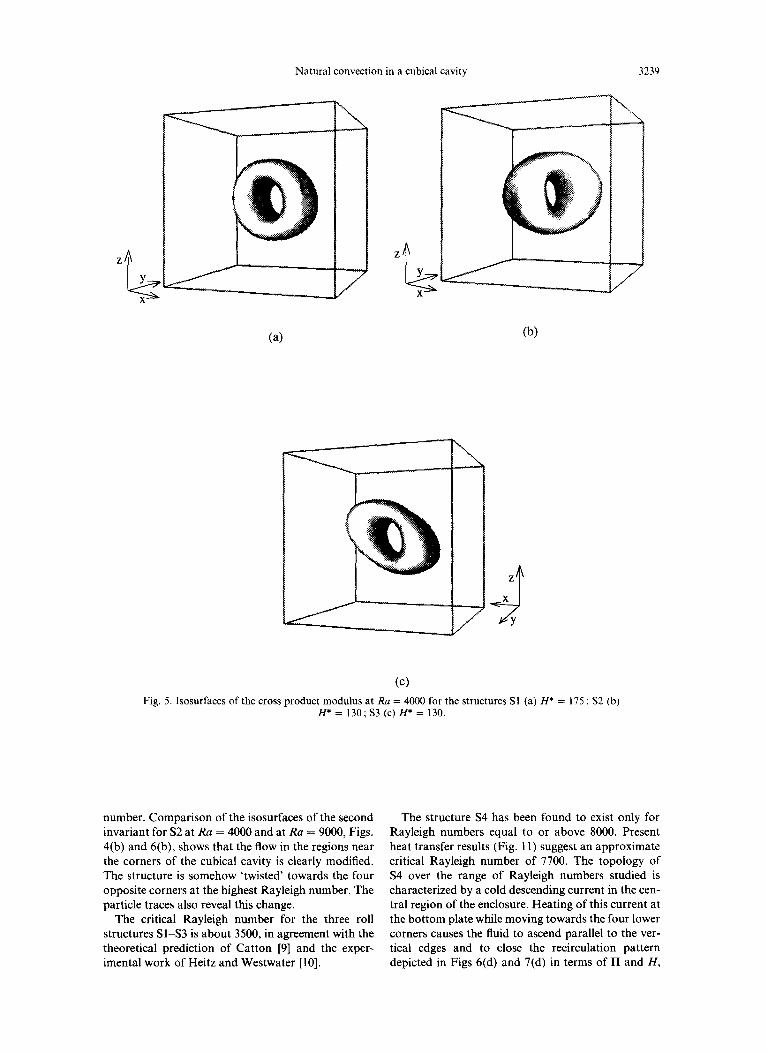
(cl Fig. 5. Isosurfaces of the cross product modulus at Ra = 4000 for the structures Sl (a) H* = 175 ; S2 (b)
H*=l30;S3(c)H*=130.
number. Comparison of the isosurfaces of the second invariant for S2 at Ra = 4000 and at Ra = 9000, Figs. 4(b) and 6(b), shows that the flow in the regions near the corners of the cubical cavity is clearly modified. The structure is somehow ‘twisted’ towards the four opposite corners at the highest Rayleigh number. The particle traces also reveal this change.
The critical Rayleigh number for the three roll structures Sl-S3 is about 3500, in agreement with the theoretical prediction of Catton [9] and the exper- imental work of Heitz and Westwater [lo].
The structure S4 has been found to exist only for Rayleigh numbers equal to or above 8000. Present heat transfer results (Fig. 11) suggest an approximate critical Rayleigh number of 7700. The topology of S4 over the range of Rayleigh numbers studied is characterized by a cold descending current in the cen- tral region of the enclosure. Heating of this current at the bottom plate while moving towards the four lower corners causes the fluid to ascend parallel to the ver- tical edges and to close the recirculation pattern depicted in Figs 6(d) and 7(d) in terms of n and H,
J. PALLARkS et al.
(a) (b)
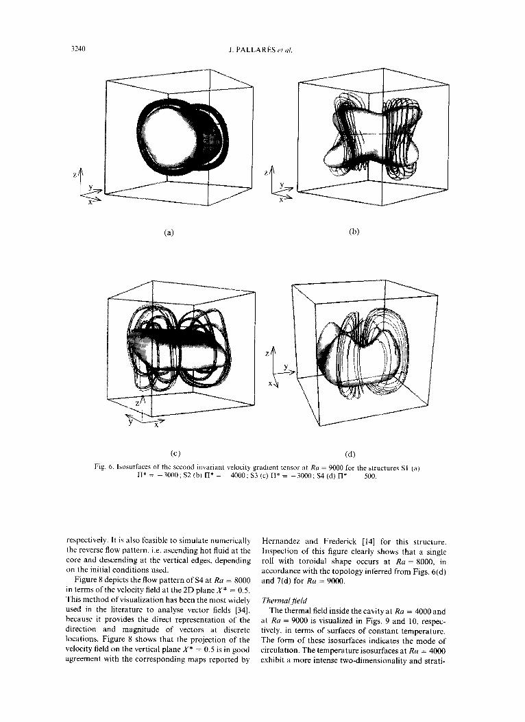
Fig. 6. Isosurfaces of the second invariant velocity gradlent tensor at Ra = 9000 for the structures Sl (a) n* = -3000; S2 (b) II* = -4000; S3 (c) II* = -3000; S4 (d) n* = -500.
respectively. It is also feasible to simulate numerically the reverse flow pattern. i.e. ascending hot fluid at the core and descending at the vertical edges, depending on the initial conditions used.
Figure 8 depicts the flow pattern of S4 at Ru = 8000 in terms of the velocity field at the 2D plane X* = 0.5. This method of visualization has been the most widely used in the literature to analyse vector fields [34], because it provides the direct representation of the direction and magnitude of vectors at discrete locations. Figure 8 shows that the projection of the velocity field on the vertical plane X* = 0.5 is in good agreement with the corresponding maps reported by
Hernrindez and Frederick [14] for this structure. Inspection of this figure clearly shows that a single roll with toroidal shape occurs at Ra = 8000, in accordance with the topology inferred from Figs. 6(d) and 7(d) for Ra = 9000.
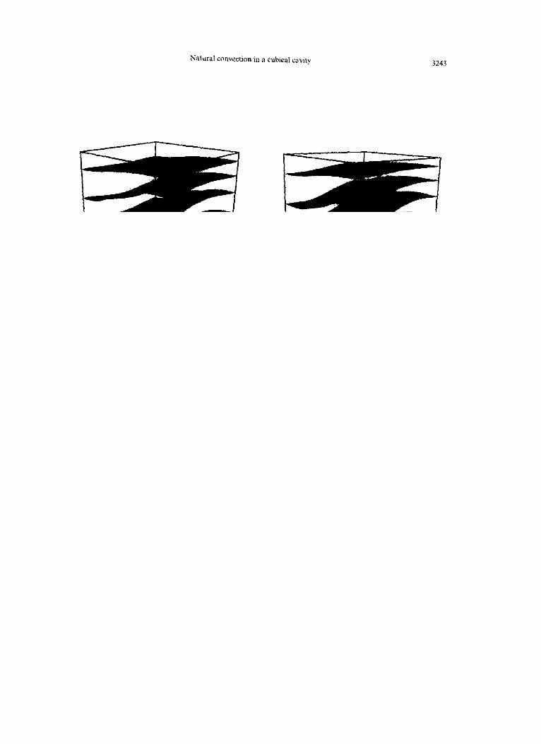
Thermal field The thermal field inside the cavity at Ra = 4000 and
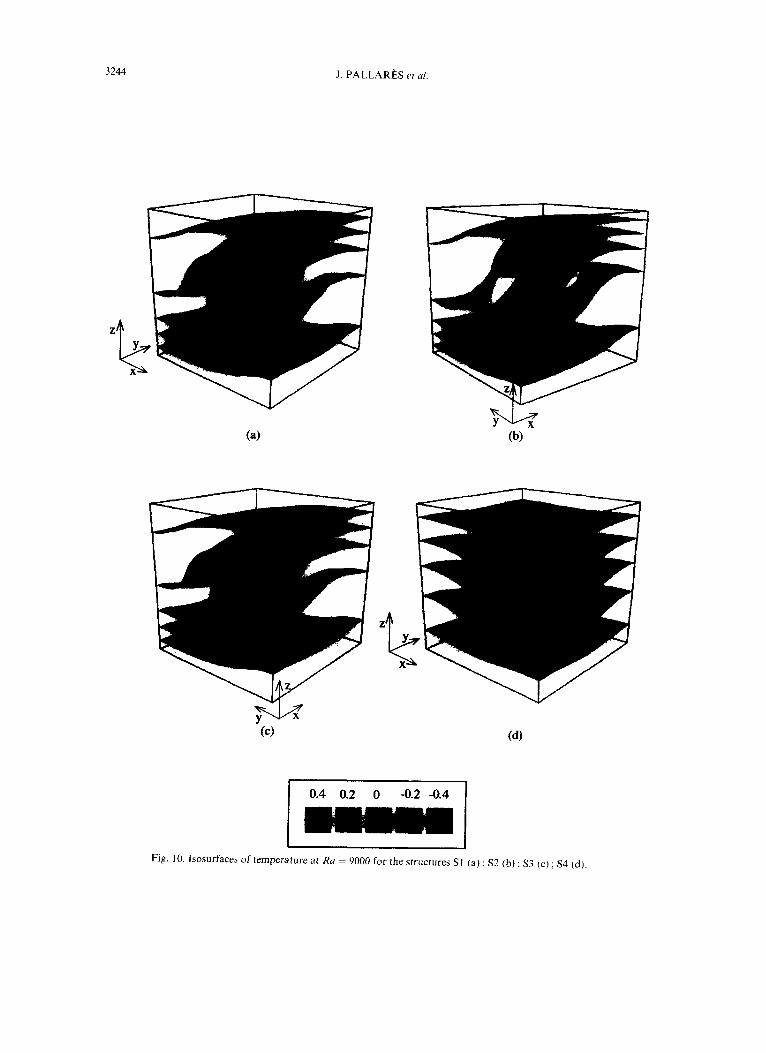
at Ra = 9000 is visualized in Figs. 9 and 10, respec- tively, in terms of surfaces of constant temperature. The form of these isosurfaces indicates the mode of circulation. The temperature isosurfaces at Ra = 4000 exhibit a more intense two-dimensionality and strati-

Natural convection in a cubical cavity 3241
(c) (4 Fig. 7. Isosurfaces of the cross-product modulus at Ra = 9000 for the structures Sl (a) H* = 1100; S2 (b)
H* = 1100 ; S3 (c) H* = 900 ; S4 (d) H* = 120.
fication than those corresponding to Ra = 9000, which, in turn, are more affected by the lateral walls. Figures 9(a) and (c) or 10(a) and (c) show that there are no obvious visual differences between the thermal fields corresponding to Sl and S3, whereas the flow patterns previously discussed for these structures reveal intrinsic structural differences between them. These results indicate that the thermal field is not a convenient way for visualizing the topology of how structures in enclosures or near walls.
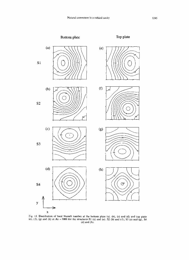
The effect of the type of structure on heat transfer rates at the top and bottom plates is shown in Fig. 11, where the 2D distribution of the local Nusselt number
is plotted for Ra = 9000. The 2D thermal fields are given in terms of lines of constant local Nusselt num- bers for the four flow structures SlLS4 identified. In these plots, a maximum absolute value of the Nusselt number corresponds to a region of impingement of an ascending or descending current, while relatively low absolute values correspond to regions of bound- ary layer flow for the fluid leaving the two plates. Figures 11 (a)-(d) and 11 (e)-(h) show, respectively, the distribution of local Nusselt numbers at the top and bottom plates for the four structures present in the flow. For Sl, S2 and S3 [Figs. 11 (a)-(g)], the distributions of the hot and cold plates are perfectly
3242 .I. PALLAReS et al
X’
, I ,‘
01
0 0.5 1
Y’ Fig. 8. Projection of the velocity vector field on the vertical
plane Z* = 0.5 at Ra = 8000 for the structure S4.
anti-symmetrical, in accordance with the presence of‘ a single rotating roll. The maps for S4 agree with a nearly toroidal structure with dominating descending currents at the vertical edges and a strong ascending current in the core.
Although the distribution of local Nusselt numbers for Sl and S3 have a very similar appearance, a detailed study of Figs. 11 (a) and (c), and 11 (e) and (g), reveals a different heat transfer behaviour. Maximum heat transfer rates occur close to the vertical walls for S3 due to the elongation of this structure towards the two opposite horizontal edges parallel to the axis of rotation. This elongation provides extra space for flow circulation causing a decrease in recirculating vel- ocities and yielding slightly lower values for the Nus- selt numbers. The maps for S2 reveal that the orien- tation of the structure along the diagonal plane produces higher heat transfer rates, but in a narrower region than for the other two single roll structures. Among all different structures. S4 is by far the less effective for transferring heat between the top and bottom plates, as indicated by the lower values of the local Nusselt numbers given in Figs. 11 (d) and (h).
Table 3 indicates the location (.u*.J*) where the maximum values of the Nusselt number occur at the hot plate, for the four structures Sl-S4. While at Ra = 4000 only Sl and S2 have different locations for the maximum heat transfer rates, at Ra = 9000 the location of the maximum value for S3 also separates from that of Sl, getting closer to the lateral wall. Maximum values are centered somewhere in the diag- onal for S2 and located near the center of the plate for S4, in accordance with the data of Figs. 11 (a)-(d).
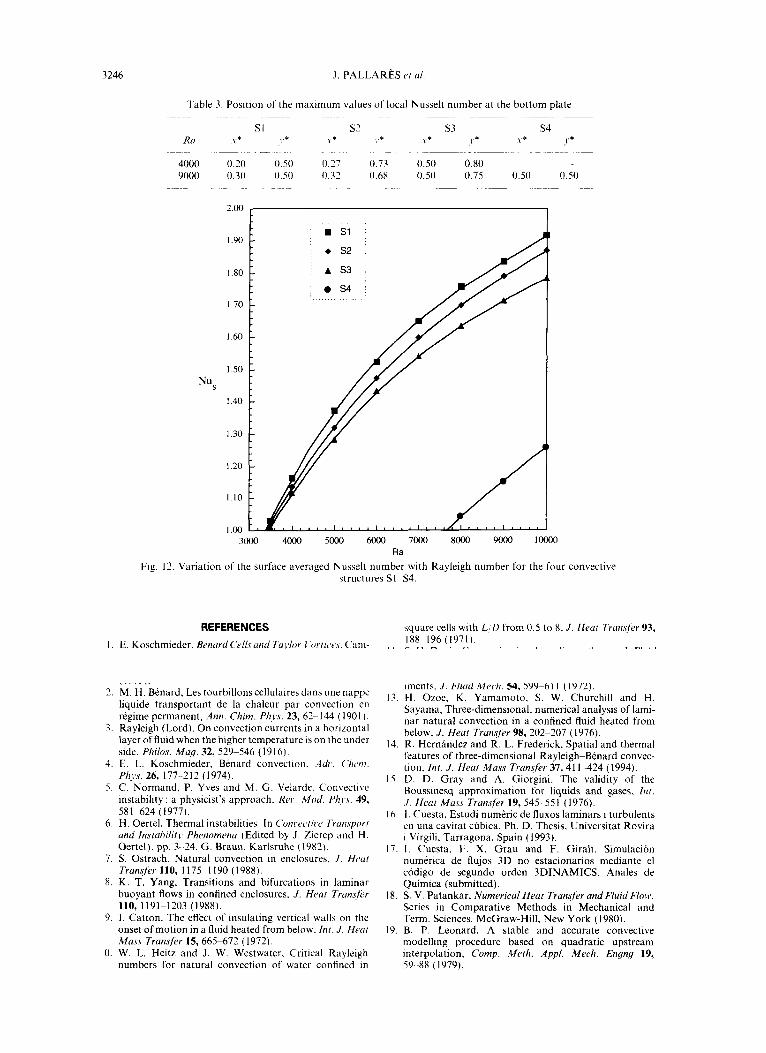
Surface averaged Nusselt numbers depend both on
the Rayleigh number and on the kind of structure present in the flow, as shown in Fig. 12. The variation of the averaged Nusselt number with Rayleigh num- ber for structures Sl-S3 is clearly different from that corresponding to S4. The same critical Rayleigh number, of approximately 3500 is observed for the first three structures (Sl-S3). while the critical value for S4 occurs at around 7700, indicating two different bifurcations of the Navier-Stokes equations. The higher critical value for S4 suggests that this structure is more influenced by the lateral adiabatic walls.
The three single roll structures Sl-S3 yield similar heat transfer characteristics. with Nusselt numbers increasing with a power of the Rayleigh number in the range 0.7-0.4. Figure 12 shows that Sl is the most efficient for transferring heat followed by S2, which is 2% less efficient, and by S3. It is interesting to note that while S3 is topologically similar to Sl, it yields even lower heat transfer rates than S2. with a 4% drop at Ru = 4000 and a 7% at Ru = 10 000. The variation of the Nusselt number with the Rayleigh number for S4 is similar to that for the single roll structures, but with transfer rates 65% lower.
CONCLUDING REMARKS
This numerical study presents a detailed description of the topology of the different convective structures present in a cubical cavity heated below, in the range 3500 < RN 6 10000, using air (Pr = 0.71) as working fluid. It is interesting to note the ability of the second invariant of the velocity gradient tensor n and the modulus of the vector product H to portray the struc- tural characteristics of the flow. While II gives closed surfaces that illustrate the structure characteristics, the 3D maps for Hdescribe the fluid venae. The spatial distributions of the four stable detected structures are influenced by the four adiabatic lateral walls which favour certain privileged orientations. Two structures, Sl and S3, have orientations parallel to two opposite lateral walls while the other two, S? and S4. are ori- ented along the diagonal of the top and bottom plates. The difference on the critical Rayleigh number for the single roll structures (SI. S2 and S3), Ra, = 3500, and for the toroidal structure S4, Ru, = 7700. suggests that there are different bifurcations of the Navier-Stokes equations. Moreover, the existence of four different structures makes the surface averaged Nusselt number dependent on the pattern adopted by the flow. The three single roll structures Sl-S3 yield heat transfer rates at the top and the bottom plates that are 65% higher that those of the toroidal roll S4. All the struc- tures are stable and do not evolve into other possible structures in the range 3500 < Ra < 10 000.
.~cX-no,~ledgrments-The financial support received from DGICYT. project PB93-0656-C02-01, is gratefully acknowl- edged.
Natural convection in a cubical cavity 3243
z
t
2
Y
X
j &&,&J
Fig. 9. kmufaces temperature at Ra = 4000 for the structures S1 (a) ; ~2 (b) ; s3 cc)
3244 J. PALLARES et al.
I I
Fig. IO. kosurfaees of temperature at Ro = 9000 for the structures St (a); ~2 (b) ; S3 cc) ; S4 cd),
Natural convection in a cubical cavity
Bottom plate
3245
Top plate
Sl
(4
s4
Y t
1
I.6 Q 0 0 1
I > X
Fig. 11. Distribution of local Nusselt number at the bottom plate (a), (b), (c) and (d) and top plate (e), (f), (g) and (h) at Ra = 9000 for the structures Sl (a) and (e) ; S2 (b) and (f) ; S3 (c) and (g) ; S4
(d) and (h).
3246
1.60 -
1.50 - Nu s
1.40 -
J, PALLARES rr ~1.
Table 3. Position of the maximum values of local Nusselt number at the bottom plate
Sl s7 S3 S4 RU Y* .1.* \-* 1.* .x* J.* \ * .I’+
4000 0.20 0.50 0.27 0.73 0.50 0.80 9000 0.30 0.50 0.32 0.6X 0.50 0.75 0.50 0.50
1.00 L
3000 4wo 5000 m 7coO 8ooo 9ooo 10000 Ra
Fig. I?. Variation of the surface averaged Nusselt number with Rayleigh number for the four convective structures SI-S4.
REFERENCES
I. E. Koschmieder. BPnurd Cells und Torlur I ‘~w/Iw.\. Cam- bridge Monographs on Mechanics and Applied Math- ematics. Cambridge University Press, Cambridge. U.K. (1993).
2. M. H. Benard. Les tourbillons cellulaires dans une nappe liquide transportant de la chaleur par convection en regime permanent, Ants. Chim. Phy.5. 23, 62-~ I44 ( 190 I ).
3. Rayleigh (Lord). On convection currents in a horirontal layer of fluid when the higher temperature is on the under side. Philas. Mug. 32, 529-546 (1916).
4. E. L. Koschmieder, Benard convection. .4(/r. C%c,nr. Plzw. 26, 177 -2 12 (I 974).
5. C. Normand, P. Yves and M. G. Velarde, Convective instability : a physicist’s approach. Rw Mod. P/II,\. 49, 581-624 (1977).
6. H. Oertel, Thermal instabilities. In Con~.e~.fire Trurzs~~o~r und Instability Phenomena (Edited by J. Zierep and H. Oertel), pp. 3- 24. G. Braun. Karlsruhe (1982).
7. S. Ostrach. Natural convection in enclosures. J. Herr/ Tran+r 110, II7551190(1988).
8. K. T. Yang. Transitions and bifurcations in laminar buoyant flows in confined enclosures, J. Heat Transfir 110, 1191~1203 (1988).
9. I. Catton. The effect of insulating vertical walls on the onset of motion in a fluid heated from below. Inr. J. Heur Mass Transfer 15, 6655672 ( 1972).
0. W. L. Heitz and J. W. Westwater. Critical Rayleigh numbers for natural convection of water confined in
square cells with L:0 from 0.5 to X. .f. Heat Trumftir 93, 1888196 (1971).
I I. S. H. Davis. Convection in a box : linear theory, /. Fluid Mrc,h. 30, 4655478 ( 1967).
12. K. Stork and U. Mtiller, Convection in boxes: exper- iments, J. Fluid Mwh. 54. 5999611 (1972).
Ii. H. Ozoe, K. Yamamoto. S. W. Churchill and H. Sayama. Three-dimensional, numerical analysis of lami- nar natural convection in a confined fluid heated from below. J. He& Trunsfer 98, 202-207 (I 976).
14. R. Hernandez and R. L. Frederick, Spatial and thermal features of three-dimensional Rayleigh-BCnard convec- tion, Int. J. Heat Mass Tran.$r 37, 41 I-424 (1994).
15. D. D. Gray and A. Giorgini. The validity of the Boussinesq approximation for liquids and gases. htr. .I. Heat Mass Trunsfkr 19, 545~ 551 (1976).
16. 1. Cuesta. Estudi numeric de fluxos laminars i turbulents en una cavitat ctibica, Ph. D. Thesis, Universitat Rovira i Virgili, Tarragona, Spain ( 1993).
17. I. Cuesta, F. X. Grau and F. Girah. Simulation numerica de flujos 3D no estacionarios mediante el codigo de Segundo orden 3DINAMICS. Anales de Quimica (submitted).
18. S. V. Patankar, Numerical Hear Trarwfer und Fluid Flow. Series in Comparative Methods in Mechanical and Term. Sciences. McGraw-Hill, New York (1980).
19. B. P. Leonard, A stable and accurate convecttve modelling procedure based on quadratic upstream interpolation. Camp. Merh. Appl. Mech. Engng 19, 59.-88 (1979).
Natural convection in a cubical cavity 3241
20. CH-Y. Perng and R. L. Street, Three-dimensional unsteady flow simulations: alternative strategies for a volume-averaged calculation, Inc. J. Numer. Meth. Fluids 28. 9.341-362 (1989).
21.
22.
23.
24.
25.
26.
27.
A. A. Amsden and F. H. Harlow, The SMAC method : a numerical technique for calculating incompressible fluid 29.
flows, Los Alamos Scientific Laboratory of the Uni- versity of California, LA-4370 (1970). P. K. Koshla and S. G. Rubin, A conjugate gradient iterative method, Comp. Fluids 9, 1099121 (1981). 30.
D. W. Peaceman and H. H. Rachford, The numerical solution of parabolic and elliptic differential equations, J. Sot. Ind. Appl. Math. 3,2841 (1955). 31.
G. Grotzbach, Direct numerical simulation of laminar and turbulent Btnard convection, J. Fluids Mech. 19, 27-53 (1982). T. Fusegi, J. M. Hyun. K. Kuwahara and B. Farouk, A
32.
numerical study of three-dimensional natural convection in a differentially heated cubical enclosure. Int. J. Hear 33. Mass Transfer 34, 1543-1557 (1991). P. Haldenwang, Resolution tridimensionnelle des equa- tions de Navier-Stokes par methodes spectrales Tch- ebycheff: application a la convectoin naturalle, Ph. D. Thesis, Universite de Provence (1984). 34. S. Ben Mabrouk. Etude numerique de la convection
naturelle en cavitt tridimensionnelle. Ph. D. Thesis, Universite de Poitiers (1984). G. De Vahl Davis and I. P. Jones, Natural convection in a square cavity : a comparison exercise, Int. J. Numer. Meth. Fluids 3,227-248 (1983). M. P. Arroyo and J. M. Saviron, Rayleigh-Benard con- vection in -a small box: spatial features and thermal dependence of the velocity field. J. Fluid Mech 235.725- 34’8 (1992). J. J. Van Wijk, A. J. S. Hin, W. C. de Leeuw and F. H. Post, Three ways to show 3D fluid flow, IEEE Compul. Graphics Appl. 14 Sept. (1994). J. C. R. Hunt, A. A. Wray and P. Moin, Eddies. streams and convergence zones in turbulent flows, Proceedings of the 1988 Summer Program, NASA-Stanford Center for Turbulence Research, 193-208 (1988). N. D. Sandham and L. Kleiser, The late stages of tran- sition to turbulence in channel flow, J. Fluid Mech. 245, 319-348 (1992). F. Hussain, New approaches to vortex dynamics : core dynamics, helical waves, and interaction with fine scale turbulence. In Eddy Structure Identification in Free Tur- bulent Shear Flows (Edited by J. P. Bonnet and M. N. Glauser), pp. 13-25 (1993). S. Shirayama, Processing of computed vector fields for visualization, J. Comp. Phys. 106, 3&41 (1993).
Related Documents