RATIONAL DESIGN OF NANOSTRUCTURED POLYMER ELECTROLYTES AND SOLID – LIQUID INTERPHASES FOR LITHIUM BATTERIES A DISSERTATION PRESENTED TO THE FACULTY OF THE GRADUATE SCHOOL OF CORNELL UNIVERSITY IN PARTIAL FULFILLMENT OF THE REQUIREMENTS FOR THE DEGREE OF DOCTOR OF PHILOSOPHY BY SNEHASHIS CHOUDHURY AUGUST 2018

Welcome message from author
This document is posted to help you gain knowledge. Please leave a comment to let me know what you think about it! Share it to your friends and learn new things together.
Transcript

RATIONAL DESIGN OF NANOSTRUCTURED POLYMER ELECTROLYTES
AND SOLID – LIQUID INTERPHASES FOR LITHIUM BATTERIES
A DISSERTATION
PRESENTED TO THE FACULTY OF THE GRADUATE SCHOOL
OF CORNELL UNIVERSITY
IN PARTIAL FULFILLMENT OF THE REQUIREMENTS FOR THE DEGREE OF
DOCTOR OF PHILOSOPHY
BY
SNEHASHIS CHOUDHURY
AUGUST 2018

© 2018 SNEHASHIS CHOUDHURY

RATIONAL DESIGN OF NANOSTRUCTURED POLYMER ELECTROLYTES
AND SOLID – LIQUID INTERPHASES FOR LITHIUM BATTERIES
Snehashis Choudhury, Ph. D.
Cornell University 2018
Advances in understanding of the basic science and engineering principles the underpin
performance of electrochemical storage technologies is imperative for significant
progress in portable electrical storage. In this regard, metal based batteries comprising
of a reactive metal (like Li, Na, Al) as anode have attracted significant attention because
of their promise of improving the anode-specific capacity by as much 10-fold, compared
to the current state-of-art Li-ion battery using graphitic anode. Perhaps their greatest
advantage lies in the possibility of using of a Li-free high-capacity cathode like oxygen
that can improve the gravimetric energy density of batteries from ~0.3kWh/kg to
~12kWh/kg (i.e. comparable to the useful energy available from combustion of
hydrocarbons). A persistent challenge with batteries based on metallic anodes, concerns
their propensity to fail by short-circuits produced by dendrite growth during battery
recharge, as well as by runaway of the cell resistance due to internal side reactions with
liquid electrolytes. The work reported in this thesis utilizes multiscale transport
modeling and experiments to fundamentally understand and to thereby develop rational
designs for polymer electrolytes and electrode – electrolyte interphases that overcome
these challenges . On the basis of a linear stability analysis of dendrite growth during

metal electrodeposition, it is shown that the length – scale on which transport occurs
near the electrodes can be as important as electrolyte modulus in stabilizing metals
against dendrite formation. To evaluate this proposal, cross-linked polymer electrolytes
were designed with tunable pore size and the stability of metal electrodeposition was
quantified in these systems. Direct visualization of electrodeposition using these
electrolytes showed remarkable agreement with the theoretical predictions.
Furthermore, when operated in a battery, the crosslinked membrane demonstrated stable
galvanostatic cycling of lithium metal anodes for several hundreds of hours.
Importantly, these studies showed that while the tendency for battery failure by
dendrite-induced short-circuits can be reduced, the issue of capacity-fading as a result
of continuous reactions of the metal with liquid electrolyte persists. Through multiscale
modeling of ion transport, artificial solid electrolyte interphase designs are proposed for
lithium-oxygen batteries to enable stable recharge and low overpotentials even with
chemically reactive liquid electrolytes.

v
BIOGRAPHICAL SKETCH
Snehashis Choudhury was born in a small town of Brajrajnagar in the state of Odisha in
India. He went to high-school in Kolkata, India. As a child, his favorite topics were
Mathematics, Chemistry and Economics. Following his high-school, he decided to
pursue Engineering over his second choice of Economics. He went to National Institute
of Technology Calicut to pursue Bachelor of Technology in Chemical Engineering in
the year 2009. The four years of experience in NIT Calicut was one of the best time of
his life, where he made several great friends and also learnt about independent research.
He joined Cornell University for his Masters of Engineering in the School of Chemical
and Biomolecular Engineering in the year 2013. He worked in the group of Professor
Lynden Archer, thereafter continued as a PhD student in the following year. In this PhD,
he started his work on designing covalently grafted hairy nanoparticles to understand
their structure and dynamics. In his second year Cornell, he developed an interest in
understanding the instabilities and thereafter stabilizing of metal-based batteries. He
found that the prior-designed hairy nanoparticles are excellent candidates in serving as
solid or gel electrolytes to inhibit battery short-circuits in lithium metal batteries.
However, a glaring failure mechanism he discovered in these metal batteries, was the
unwanted side reactions at the battery interfaces causing slow fading in the capacity. He
took this challenge head-on by designing artificial interfaces to inhibit these side
reactions, thereby enabling stable cycling of a solid polymer electrolyte in a high energy
metal battery. He will always be grateful to all the collaborators and group members for
their constant support not only in research but also in other endeavors.

vi
DEDICATED TO MY FAMILY, MY STUDENTS AND TO ALL THOSE WHO
LIVE WITH A PASSION

vii
ACKNOWLEDGMENTS
I have to apologize as my words will not do justice to all the help and support I have
received from everyone in my PhD journey and in my life. I would like to firstly thank
Prof. Lynden Archer for his help not only in my PhD work but also in my career
counseling. His knowledge in a wide spectrum of subjects and his passion for science
has always driven me to improve every single day I spent at Cornell. I greatly appreciate
the help from my committee members Prof. Yong Joo and Prof. Geoffrey Coates. I
greatly enjoyed the discussions with them on my research.
Perhaps one of the most satisfying and inspiring experience at Cornell was my Teaching
Assistant responsibilities. Overall, I served as a TA for four different times in the
Chemical Engineering and Physics department. I want to thank every student in these
classes, who have inspired me and helped me in discovering my love for teaching. I am
grateful to Prof. Julius Lucks, Prof. William Olbricht and Prof. Chris Alabi for providing
me guidance and as well as independence in conducting lectures and recitations in my
TA classes.
Thanks to all the former and current members of Archer group. I am greatly thankful to
Rajesh for being my mentor in first year at Cornell as a Master of Engineering student.
I have to say, I wouldn’t have been in the PhD program without Rajesh’s guidance. I
am sincerely grateful to Akanksha who have been a great friend, mentor and
collaborator. I will always miss our long conversations about research, people and life

viii
with her while simultaneously working long hours in lab. Also, in course of my PhD, I
met a great human being and researcher, Zhengyuan, whose dedication towards research
was extraordinary. I thank him for making my life so easy in handling different projects
and serving as a great partner in everything I worked on in my PhD. Over the five years
at Cornell, I have worked with several undergraduate and masters students who have
been more of my mentor than vice-versa. I am thankful to Charles, Dylan and Sanjuna
for their constant support in research and making my experience in the group so
memorable.
A big thanks to Himanshu, Prayag, Samanvaya, Sanjuna, Dylan, Ritesh, Pooja,
Zhengyuan, Anubhav, Yue, Alex, Kaihang, Nijam, Rohit, Prajwal, Rahul, Mun Sek,
Sampson for their strong support in my in research and life. I am greatly obliged to all
my collaborators outside Archer group, Prof. Tomas Arias, Prof. Mendoza Cortes, Prof.
Ravishankar Sundaraman, Prof. Donald Koch and Dr. A. Nijamudheen. I am specially
grateful to Professor Lena Kourkoutis and Dr. Michael Zachman for their constant
support in cryo-electron microscopy. Also, I am thankful to all the staff scientists for
their help at Argonne National Lab and Cornell High Energy Synchrotron Facicility.
Lastly, and most importantly, I want to thank my parents and brother for their love and
sacrifice all through my life.

ix
TABLE OF CONTENTS
ABSTRACT iii
BIOGRAPHICAL SKETCH v
DEDICATION vi
ACKNOWLEDGEMENT vii
CHAPTER 1: INTRODUCTION……………………………………………………...1
1.1!The Lithium Metal Battery………………………………………………………...2
1.2!Rational Design Principles……………………………………….………………...5
1.2.1! Nanostructured Electrolytes……………………...…………………….………5
1.2.2! Solid-Liquid Interphases…………………………………………...….…...…10
1.3!Outline…………………………………………………………..……..………….19
CHAPTER 2: SELF-SUSPENDED SUSPENSIONS OF COVALENTLY GRAFTED
HAIRY NANOPARTICLES …………………………………………………….......27
2.1!Abstract……………………………………………...............................................28
2.2!Introduction………………………………………………………………..……...28
2.3!Experimental Section…………………………………………………..................31
2.3.1 Synthesis of Self-Suspended Covalently Grafted Nanoparticles……………….31
2.3.2 Characterization………………………………………………………………...33
2.3.3 Small Angle X-Ray Scattering Measurements…………………………………33
2.3.4 Rheology Measurements………………………………………………………..34

x
2.4 Results and Discussion……………………………………………………………34
2.5 Conclusion……………………………………..…………………………………48
Acknowledgement……………………………………..……………………………..49
References……………………………………..………………………………….…..50
Appendix……………………………………..……………………………….......…..60
CHAPTER 3: A HIGHLY CONDUCTIVE, NON-FLAMMABLE POLYMER-
NANOPARTICLE HYBRID ELECTROLYTE ………………………………….....69
3.1 Abstract……………………………………………...............................................70
3.2 Introduction………………………………………………………………..……...71
3.3 Materials and Methods……………………………………………………………73
3.3.1 Synthesis………………………………………..………………………………73
3.3.2 Characterization………………………………………..…………….…………74
3.3.3 Electrochemical Measurements……………………………..…………….……75
3.3.4 Characterizing Flammability……………………………………………………75
3.4 Results and Discussion………………………….………..…………….…………77
3.5 Conclusion………………………….………..…………….…………………..…89
References……………………………………..………………………………….…..91
Appendix……………………………………..……………………………….......…..98
CHAPTER 4: HYBRID HAIRY NANOPARTICLE ELECTROLYTES STABILIZE
LITHIUM METAL BATTERIES………………………………………………..…102

xi
4.1 Abstract…………………………………………….............................................103
4.2 Introduction………………………………………………………………….…..103
4.3 Materials and Methods…………………………………………………………..107
4.3.1 Synthesis………………………………………………………………………107
4.3.2 Characterization…………………………………………………………….…108
4.3.3 Electrochemical Measurements…………………………………………….....109
4.3.4 Analyzing the Columbic Efficiency…………………………………………...110
4.3.5 Cell Lifetime Study……………………………………………………………111
4.4 Results and Discussion………………………………………………………..…111
4.4.1 Physical Characterization and Ion Transport…………………………………...73
4.4.2 Structural Factor Analysis………………………………………………..……114
4.4.3 Variation of Interfacial Resistance……………………………………….……118
4.4.4 Surface Characterization of Li Anode…………………………………………120
4.4.5 Enhanced Electrochemical Stability of Nanocomposites…………………..…123
4.4.6 Analyzing Galvanostatic Performance……………………………………...…124
4.5 Conclusion………………………………………………………………………128
References………………………………………………………………………...…130
Appendix……………………………………………………………………….……141
CHAPTER 5: A HIGHLY REVERSIBLE ROOM TEMPERATURE LITHIUM
METAL BATTERY BASED ON CROSS-LINKED HAIRY NANOPARTICLES.146
5.1 Abstract…………………………………………….............................................147
5.2 Introduction………………………………………………………………….…..147

xii
5.3 Methods……………………………………………………………………...…..150
5.3.1 Materials………………………….………………………………...………….150
5.3.2 Nanoparticle-Polymer Crosslink Synthesis and Composite Electrolyte
Preparation………………………….………………………………...…….……….150
5.3.3 TEM And Small Angle X-Ray Scattering………………………….……...….151
5.3.4 Mechanical Properties………………………….……..................................….152
5.3.5 Electrochemical Characterization……………………….….……...............….152
5.3.6 Cell Lifetime and Failure Studies………………………….……................….153
5.3.7 Measuring the Coulombic Efficiency………………………….……..........….153
5.3.8 Half-Cell Testing………………………….…………………………..........….154
5.4 Results…………………………………………………………………..........….155
5.4.1 Synthesis and Physical Characterization of Crosslinked Membrane…........….155
5.4.2 Mechanical and Electrochemical Properties of Crosslinked Membrane….......159
5.4.3 Analyzing Stability of Lithium Electrodeposition Using Crosslinked
Membranes…………………………………………………………………………..162
5.5 Discussion…………………………………………...…………………………..169

xiii
Acknowledgments…………………………………………...…………………..…..170
References………………………………………………………………………...…171
Appendix……………………………………………………………………….……179
CHAPTER 6: CONFINING ELECTRODEPOSITION OF METALS IN
STRUCTURED ELECTROLYTES…………………………………………….......193
6.1 Abstract…………………………………………….............................................194
6.2 Significance………………………………………………………………….…..195
6.3 Introduction………………………………………………………………….…..195
6.4 Materials and Methods…………………………………………………………..198
6.4.1 Materials………………………….………………………………...………….198
6.4.2 Linear Stability Analysis………………………….…………………………...198
6.4.3 Crosslinked Hairy Nanoparticles Synthesis………………………….…….….198
6.4.4 Dielectric Spectroscopy………………………….………………...………….198
6.4.5 Transmission Electron Microscopy………………………...……...………….199
6.4.6 Scanning Electron Microscopy…………………….…….………...………….199
6.4.7 Mechanical Properties………………………….……………………..……….199
6.4.8 Direct Visualization Experiments………………………….………………….200
6.5 Results…………………………………………………………………..........….200
6.5 Conclusion………………………………………………………………………216
Acknowledgements……………………………..…………...…………………..…..217
References………………………………………………………………………...…218

xiv
Appendix……………………………………………………………………….……224
CHAPTER 7: SOFT COLLOIDAL GLASSES AS SOLID-STATE
ELECTROLYTES……………………………………………...…………….……..239
7.1 Abstract…………………………………………….............................................240
7.2 Introduction………………………………………………………………….…..240
7.3 Results and Discussions…………….…………………………………..........….243
7.3.1 Synthesis and Chemical Analysis……………………..…………...………….243
7.3.2 Calorimetry and Ion Transport………..…………………………...…………..247
7.3.3 Structure Analysis and Rheology………..…………………………...………..250
7.3.4 Analysis of Electrochemical Performance………..…………………….……..257
7.5 Conclusion………………………………………………………………………261
Acknowledgements……………………………..…………...…………………..…..261
References………………………………………………………………………...…263
Appendix……………………………………………………………………….……270
CHAPTER 8: SOLID POLYMER INTERPHASES FOR LITHIUM METAL
BATTERIES………………………………………………………………….……..285
8.1 Abstract…………………………………………….............................................286
8.2 Introduction………………………………………………………………….…..286
8.3 Results and Discussion…………..…………….…………………………….…..289
8.4 Methods……………...…………..…………….…………………………….…..303
8.4.1 Fabrication of crosslinked polymer network and coated lithium………..…….303

xv
8.4.2 Material Characterization………………………………………………..…….303
8.4.3 Electrochemical Characterization………………………….……...…………..304
References………………………………………………………………………...…306
Appendix……………………………………………………………………….……309
CHAPTER 9: STABILIZING POLYMER ELECTROLYTES IN HIGH-VOLTAGE
LITHIUM BATTERIES……………………..……………………………….……..318
9.1 Abstract…………………………………………….............................................319
9.2 Introduction………………………………………………………………….…..320
9.3 Results and Discussion…………..…………….…………………………….…..323
9.4 Methods……………...…………..…………….…………………………….…..303
9.4.1 Computational Details………………………………………….………..…….343
7.4.2 Experimental Details…...………………………………………………..…….343
References………………………………………………………………………...…344
Appendix……………………………………………………………………….……350
CHAPTER 10: LITHIUM FLUORIDE ADDITIVES FOR STABLE CYCLING OF
LITHIUM BATTERIES AT HIGH CURRENT DENSITIES……………….....…..377
10.1 Abstract………………………………………….............................................378
10.2 Introduction……………………………………………………………….…..378
10.3 Experimental Section…………….……………………………...…..........……381
10.3.1 Materials……………………...……………………..…………...………….381
10.3.2 Methods…………………….………..…………………………...…………..382

xvi
10.3.3 Electrochemical Characterizations…..…..………………………….………..382
10.4 Results……………………………………………..…………………….……..383
Acknowledgements……………………………..…………...…………………..…..397
References………………………………………………………………………...…398
Appendix……………………………………………………………………….……403
CHAPTER 11: DESIGNING SOLID-LIQUID INTERPHASES FOR SODIUM
BATTERIES………………………………………………….……………………..407
11.1 Abstract…………………………………………...............................................408
11.2 Introduction……………………………………………………………..….…..408
11.3 Methods………………………………………………………………..…...…..412
11.3.1 Materials……………………….………………………………...……..…….412
11.3.2 Sodium Bromide and Other Halide Coating Formation ……………..……...412
11.3.3 Physical Characterization…………………..………………………..…...…..413
11.3.4 Electrochemical Characterization…………………..……………...….....…..414
11.3.5 Scanning Electron Microscopy…………………………………...….......…..414
11.3.6 Focused Ion Beam/Scanning Electron Microscopy………………….......…..415
11.3.7 In Situ Visualization Studies…………………..……………...…….....……..415
11.3.8 Cell Lifetime and Failure Studies…………………………………...….........416
11.3.9 Sulfur-Pan Cathode Cycling…………………..…………….....….................416
11.4 Results…………………..……………...…........................................................417
11.4.1 Joint Density-Functional Theory (JDFT) Study of SEI………..…………….417
11.4.2 Formulation and Stability a NaBr-Based SEI Layer on Sodium Metal…...…420

xvii
11.4.4 Electrodeposition of Sodium Metal with NaBr Coated Anode……………....428
11.5 Discussion……………………..……..…………...…………………..……......434
Acknowledgements……………………………..…………...…………………..…..435
References………………………………………………………………………...…436
Appendix……………………………………………………………………….……442
CHAPTER 12: ELECTROLESS FORMATION OF HYBRID LITHIUM ANODES
FOR HIGH INTERFACIAL ION TRANSPORT…………………………………..450
12.1 Abstract………………………………..………….............................................451
12.2 Introduction……………………..………………………………………….…..451
12.3 Results…………………………..……………………………………..........….454
12.3 Conclusion……………......……………………………………………………468
Acknowledgements……………………………..…………...…………………..…..469
References………………………………………………………………………...…470
Appendix……………………………………………………………………….……475
CHAPTER 13: DESIGNER INTERPHASES FOR THE LITHIUM-OXYGEN
ELECTROCHEMICAL CELL…………………………..………………………….488
13.1 Abstract…………………………………………………………………….…..489
13.2 Introduction………………………………..……………………………….…..490
13.3 Results and Discussion………………………………..……...…………….…..494
13.3.1 Understanding the Anode Protection Mechanism……………………….…..494
13.3.1.1 Characterization of the Anode…………………...…………………….…..494

xviii
13.3.1.2 Lithium-Electrolyte Stability…………………...…………………….……500
13.3.1.3 Anode Protection Mechanism…………………...…………………………504
13.3.2 Understanding the Cathode Stabilization Mechanism…………………….…506
13.3.2.1 Characterizing Cathode Products…………………...…………...…………506
13.3.2.2 Cycling Performance…………………...……………………......…………508
13.3.2.3 Cathode Stabilization Mechanism…………………...…………….………511
13.4 Conclusions………………………………………………………………….…512
References………………………………………………………………………...…514
Appendix……………………………………………………………………….……522
BIBLIOGRAPHY………………………………………..………………………….534

1
CHAPTER 1
INTRODUCTION

2
1.1 The Lithium Metal Battery
Upsurge in consumer electronics and electrical appliances have necessitated the need
for high power, lightweight, long lasting batteries at low cost. In this regard, lithium
ion batteries have found their place in the commercial world because of their
robustness and reversibility1–3. Moving forward in the line of energy storage
advancement, the next generation batteries are predicted to also base on lithium metal,
however, instead of using a graphitic anode for lithium intercalation, an absolute
lithium film can serve as anode. Although, this replacement may seem trivial, use of
lithium metal anode can mean a paradigm shift in battery technology. Some of the
advantages of a lithium metal full cell battery over lithium ion batteries are as follows:
1) High power density, because rate of intercalation of Li ions into graphite anode is
much slower than Li ion plating onto lithium anode; 2) Low cost, as use of Li anode
avoids the cost of graphite in the anode; 3) Lightweight, for not using graphitic anode;
4) High energy density, use of Li anode provides the liberty of using many cathode
materials like sulfur and oxygen that have the higher specific capacity than any
currently used cathode4; 5) Batteries can be made in variety of form factors.
However, the main bottleneck in the practicality of Lithium metal batteries is the
safety issue and low reversibility. During the alternate charge and discharge cycles,
lithium may get unevenly deposited onto the anode, resulting in growth of dendritic
structures having the potential of puncturing the separator and causing internal short
circuit and at times explosion1. The low reversibility is related with the slow
degradation of electrolyte due to parasitic reactions with the anode5. Although, these
problems also persistent in Lithium ion batteries, they exacerbated in a Lithium metal

3
battery, where the reactive surface of lithium is exposed to the organic electrolyte.
Broadly, these issues can be divided in three categories-; 1) morphological instability -
inevitable dendritic deposition, especially at high current densities; and 2) chemical
instability - unregulated reactions at electrode-electrolyte interface and 3)
hydrodynamic instability - unstable ion transport that create space charge near the
electrode surface. We believe that the origin of these instabilities is a three-stage
process6, as shown in Figure 1.1. In stage-1, the electrolyte passivates the Li metal
electrode by side reactions owing to its high reactivity, however this passive layer so
called solid-electrolyte interface (SEI) is non-uniform, creating gradients of surface
conductivity. In stage-2, the Li ions selectively electrodeposit on regions having
higher conductivity, leading to formation of uneven and sharp nucleates (deposits).
These rough deposits increase the surface area of contact between the electrode and
electrolyte, thus amplifying the unwanted parasitic reactions resulting in battery-
capacity fade over time. Finally, in stage-3, by repeated battery cycling, the lithium
ions continue to deposit on the tips of these nucleates due to higher local electric field
causing the formation of needle like dendrites that grow bigger in size to ultimately
short-circuiting the cell, which often accompanied with fire and explosions. My PhD
thesis is bifurcated in two major topics- 1) designing theory-inspired nanostructured
electrolytes for preventing the proliferation of dendrite. 2) understanding the role of
interfacial chemistry in the nucleation step of electrodeposition. There has been
extensive scientific research in this field for past four decades to understand the origin
of such instabilities in a battery and techniques to mitigate them.

4
Figure 1.1 Schematic showing different stages of instabilities during electrodeposition
on a lithium metal anode

5
1.2 Rational Design Principles
The three frameworks discussed in the last section all lead to different
recommendations for enabling Li anodes. Some common methods include use of
additives for stabilizing electrode-electrolyte interface7–12, high mechanical strength
separator for providing compression force on the surface13–16, nanostructured
electrolytes for controlling the length-scale of electrodeposition17–19 and ion transport
modification using single ion conducting electrolytes20,21. Overall, thee strategies have
led to significant attention among the researcher to fundamentally understand the
transport and thermodynamic aspects of nanostructured electrolytes and solid-liquid
interphases. The on-going efforts in these two broad areas are discussed here:
1.2.1 Nanostructured Electrolytes
Solid-state electrolytes have recently gained significant attention because of the
general notion in battery literature that although chemical modifications in liquid
electrolyte recipe can extend the lifetime of battery to a significantly large timescale,
but it cannot explicitly ensure safety. Previous work by Monroe and Newman using
solid mechanics showed that dendrite growth can be prevented using a solid
electrolyte with modulus twice that of the electrode.22,23 In this regard, ceramics have
been of primary focus of investigation as candidates for SSE’s. Previously, Dudney et
al.24 designed a SSE with LiPON chemistry that demonstrated over 10,000 cycles of
galvanostatic charge and discharge in Lithium vs. NMO configuration, with minimal
capacity fading and close to 100% coulombic efficiency as shown in Figure 1.2. The
long cycle-life performance sets a benchmark for rechargeable battery operation;

6
Figure 1.2: LiPON based solid – state electrolyte used in Li||NMO micro battery
showing stable performance for over 10,000 cycles with high capacity retention and
coulombic efficiency. (Adapted from: Li, J., Ma, C., Chi, M., Liang, C. & Dudney, N.
J. Solid Electrolyte: the Key for High- Voltage Lithium Batteries. Adv. Energy Mater.
5, 1401408 (2015))

7
which to best of our knowledge hasn’t been reported in batteries based on liquid
electrolytes. However, there are major shortcomings associated with the LiPON solid
electrolyte and the most notable is the low ionic conductivity (<10-5 S cm-1) at room
temperature. It is for this reason, the cell reported in the mentioned work is micro-
scale and similar performance hasn’t been replicated in pouch level or even coin-type
cell configurations. There has been intensive research in this area for the chemical
modification of the ceramic electrolytes for improving the conductivity, however the
electrochemical stability is seen to deteriorate. Another major disadvantage with the
ceramic-based solid electrolytes is the poor solid-solid contact between electrode and
electrolyte that causes major setback in the interfacial conductivity. Further, the
brittleness and high cost of raw material imparts a huge challenge in terms of
commercialization of the metal batteries with inorganic solid electrolytes.
Recent on nanostructured electrolytes based on alumina membrane18,25 and crosslinked
hairy nanoparticles17 that has gained significant attention owing to the unprecedented
stable cycling and simplicity of implementation. Tikekar et al.16,26 using linear
stability analysis of dendrite growth analyzed different properties of electrolyte
components required for ‘dendrite-free’ battery operation. In a nutshell, the electrode
surface was modeled a perturbation equation: Hc = L + Hc’eVt eikx where, σ represent
the dendrite growth rate and k as the inverse deposition length-scale. The growth rate
was further shown to depend on multiple factors like surface tension, modulus and
anion transference number of the electrolyte. On analyzing dendrite growth with
during small electrode - perturbations (that represent the initial nucleation size during
deposition), it was seen that under typical operating conditions, the surface tension of

8
electrolyte-electrode interphase plays a major role in limiting the growth rate of
dendrites at low-order nucleate sizes, in fact below a critical size absolute stability can
be attained as shown in the state diagram in Figure 1.3. Further it is evident that the
critical nucleate size can be manipulated by varying anion transference number and
the electrolyte modulus. In light of these revelations, we systematically designed
nanoporous alumina separator with varying pore-size. It was seen that pore-size
correlated with the deposition length-scale, such that the high-modulus separator
framework restricted the higher-than-pore dendrite growth. Thus, it was possible to
eliminate battery failure by short circuits even in liquid electrolytes. Building on this
diagnostic experimentation, we designed polymer composite membrane using
crosslinked hairy nanoparticles for a scalable and low-cost solution. The membrane
was designed by interlinking polyethylene oxide grafted silica nanoparticles with
polypropylene glycol based cross-linker. In contrast to most previously reported
polymer electrolytes, the crosslinked membrane simultaneously showed good
mechanical strength (~1MPa) and high ionic conductivity at room temperature
(~5mS/cm), which is a consequence of the high crosslinking node points in these
membranes. Direct visualization experiments were performed to understand the effect
of pore-size on dendrite growth, which showed remarkable agreement with the
theoretical predictions. Furthermore, when operated in a battery, the crosslinked
membrane showed one of the highest short-circuit time compared to similar
electrolytes reported in the literature. Unlike previous studies of nanocomposite
electrolytes where nanoparticles were used as fillers in polymer solutions, this was one
of the first studies, where nanoparticles were linked with polymer matrix using

9
Figure 1.3: Theoretical state diagram showing how different parameters like surface
tension, deposit size, transference number or modulus affects the deposition stability

10
covalent bonding. Consequently, there have several follow-up studies involving
synthesis of advanced materials with similar architecture for energy applications.27–31
Other nanostructure designs for inhibiting dendrite growth include on single ion
conducting electrolytes with silica nanoparticle fillers with sulfonate groups tethered
on their surface21 as well as UV-crosslinked pegylated sulfonic groups32 (see Figure
1.4). These electrolytes have been reported to have transference number higher than
0.8, while having high ionic conductivity at room temperature. As previously
mentioned, the high transference number or fixed anionic species lowers the threshold
of instability during electrodeposition, thus it was observed that stable surface could
be obtained with traditional separators. In another set of studies, it was reported that
ionic liquids (eg. Imazolium, piperidium) when tethered to the silica nanoparticle
surface33,34, or crosslinked by electric field demonstrated stable cycling in lithium
metal batteries35. These observations throw light on two different stabilizing
mechanisms; ionic liquids act as supporting electrolytes in battery electrolyte, such
that these species tend to crowd on specific unstable electrode regions thereby
normalizing the overall electric field. Also, the silica nanoparticles as well as ionic
liquids serve as stabilization agents for the SEI layer for preventing side reactions.36
Thus, it is clear that once can achieve significant gain in both scientific knowhow and
battery performance on combining and unifying these stabilizing agents.
1.2.2 Solid-Liquid Interphases
Chemical modification of the solid-electrolyte interphase (SEI) is an elegant way of
eliminating the dendrite forming nucleates. Conventional electrolytes form a relatively
thick and insulating SEI layer on the Li metal, which cracks during Li ion insertion

11
a b c
d e
Figure 1.4: Ionic polymers and functionalized nanoparticle salts: (a)
nanoparticle grafted with sulfonic acid-lithium salts; (b) polymerized ionic
membrane; (c) polarization showing >1500 stable cycling with ionic membrane;
(d) ionic liquid functionalized silica nanoparticles; (e) comparison of short circuit
time of IL based nanoparticles with control liquid electrolytes

12
and desertion, exposing fresh metal to the electrolyte leading to repeated formation of
interfacial species, which can consume the electrolyte. The chemical modifications in
this context apply to an artificial SEI layer, which often comprises of a different
chemistry from the bulk electrolyte by use of additives or thin film technology. While
the behavior of the interface appears in the aforementioned theories in form of the
surface energy, the interface and the interfacial layers are not explicitly modeled,
rendering this approach a somewhat trial-and-error effort.
Recently, a Stanford group showed that ~99% coulombic efficiency can be achieved
for a LMB by a two-fold anode protection technique 33 comprised of: 1) stable SEI
forming electrolytes with additives, and 2) a thin-film protective coating of
interconnected hollow carbon nanospheres that shield the anode preventing direct
contact with electrolyte 33. This result provides a futuristic perspective toward stable
lithium metal battery by combining the benefits of a stable electrolyte and a thin-film
protector.
Aurbach et al. (2002)5 realized that no electrolytes are stable when in contact with
lithium metal causing the formation of a passivation layer that worsens at high charge
and discharge rates due to the large volume changes. However, some electrolytes have
indeed shown to form a more stable SEI layer than others. For example, 1,3 Dioxalane
(DOL) undergoes ring opening reaction at the Li surface to form an elastic surface
layer of polydioxalane oligomers that expand and contract with lithium insertion and
desertion 34. Similarly, glyme based electrolytes like Dimethoxyethane (monoglyme),
diglyme, tetraglyme are also good for formation of alkoxy based SEI (ROLi), which
stabilizes electrodeposition in both Li and Na metal batteries 35, 36. In contrast,

13
Propylene Carbonate (PC) and other carbonate-based electrolytes form a very
unstable, thick and insulating passivation layer mostly comprising of Lithium
Carbonate (Li2CO3) that can yield a maximum efficiency of ~77% in absence of any
additives.37 Thus, it is evident that the chemical composition of the interfacial layer is
of utmost importance in determining the degree of coulombic stability.
Recently, Joint Density Functional Theory (JDFT) calculations 38 revealed that surface
diffusion barriers for Li are much lower in halide salts (LiBr, LiI, LiF) compared to
regular SEI salts like LiOH and Li2CO3 (see Figure 1.5). This means that Li ions can
move laterally and rearrange on the interfacial layer before getting deposited as Li
atoms, thus having a lesser chance of forming dendritic nucleates. Based on this
concept, Lu et al. 39 used LiF additive in the electrolyte that showed remarkable results
in terms of dendrite suppression and capacity retention (see Figure 1.6). An LiF rich
SEI layer can also act as a thin film barrier between the anode and electrolyte, which is
recently confirmed by coulombic efficiency measurements in presence of carbonate-
based electrolytes resulting in over 10% improvement40. In other studies, an interfacial
layer of LiF is formed by using fluoride-based additives in the electrolyte. These
include Hydrogen Fluoride (HF)41 and Fluoro-ethylene Carbonate (FEC), which
stabilizes both Li metal 42 and Silicon based anodes 43 giving very high capacity for
several cycles. Use of dual salt of LiTFSI and LiFSI is also one such technique, where
the side reaction between these two salts in presence of lithium metal forms a thin
layer of LiF that improves the efficiency of the battery 34. Excess use of salt (near
saturation point), LiFSI in DME electrolyte leads to the same outcome as it is known

14
Figure 1.5: Bar Chart showing the Surface Diffusion Barrier for various compounds
typically exist in the interfacial layer of lithium or sodium metal battery cycling using
liquid as well as solid superionic electrolytes

15
from computational chemistry methods that, LiFSI decomposes to LiF, which
ultimately protects both the anode and cathode 35.
There have been several other additives used in LMBs for improving the battery
performance. Of these, Lithium Nitrate (LiNO3) is a prominent candidate, because its
presence in the electrolyte can significantly improve the efficiency of a Lithium sulfur
battery to nearly 100%, whereas a neat electrolyte has below 60% efficiency due to
polysulfide shuttling that attacks the lithium metal continuously causing corrosion and
failure 44, 45. While the mechanism behind this phenomenon is still debatable, Aurbach
et al (2009) 46 shed some light on the abundance of oxy-sulfur and oxy-nitrogen
species in the SEI layer of lithium in presence of LiNO3 and polysulfides. It can be
inferred that these species prevent the access of polysulfides to fresh lithium; even the
smooth and compact morphology of the SEI layer, points toward the same direction 44.
A similar behavior is also seen when the lithium anode is protected by a layer of Li3N,
which possess the additional advantage of high Li conductivity 61. Other additives
include Vinylene Carbonate 47–49, Sultones 50, 51, LiBOB52, 53, and many others. Some
of these additives have additional advantages. For example, alkyl phosphates and
fluorine-based additives act as flame-retardants by reducing the self-heating rates
significantly 54.
As the investigation towards finding the right additive for LMB intensifies, current
trends indicate that previously used additives for graphite-based lithium ion batteries
work efficiently with appropriate compositions. It is however, clear, that additives-
based lithium battery stabilization is a rather empirical science that depends upon the
battery configuration as well as component combinatorics. A recent study shows that

16
Figure 1.6: Strip Plate measurement using symmetric lithium cell showing stable
cycling with LiF added electrolyte in black in contrast to sudden short circuit with a
liquid electrolyte without any additive.

17
rationalistic selection of additives can dramatically improve the specific capacity of a
Li-O2 battery with a high energy efficiency of ~93.2% for several hundred cycles even
in presence of water 55. Using relatively high concentration of LiI additives promotes
the formation of LiOH in presence of water on cathode surface. This gives lower
insulating properties and LiOH easily reduced in presence of iodide anion that serves
as a redox mediator 55.
The second approach in lithium metal protection is ex-situ formation of a thin-film that
serves as artificial SEI layer protecting the anode from parasitic reactions with
electrolytes and dendrite formation. This is a multidisciplinary field where a broad
range of techniques can be utilized to manufacture thin-films on lithium. This
approach can also benefit from the two previous practice methods viz. modification of
transport and enhancement of elasticity, providing a rationale for design. The work of
Song et al. (2015) 18 employing Nafion as surface protection layer for Li anodes
demonstrates this confluence of methods. Another recent example is the use of Atomic
Layer Deposition (ALD) technique for depositing a monolayer of alumina on lithium
surface 56. An emerging ex-situ coating of lithium metal anode include usage of a
secondary metal coating based on tin (shown in Figure 1.7) or indium that can act as a
host for the lithium ions to alloy or intercalate before electrodeposition Such a
monolayer works excellently for preventing corrosion of lithium metal from not only
the electrolyte but also ambient air.42,43 In another study, Polyacrylonitrile (PAN) was
oxidized to enhance ion transport and electrospun to form PAN nanofibers, which was
then placed on the electrode surface 57. This nanostructured network allowed smooth
electrodeposition by confining the lithium ion plating inside the network. The other

18
Figure 1.7: Direct Visualization experiment with and without protection with a Tin
coating. The control lithium shows dendritic rough deposits, while the tin protection
slows down the growth rate.

19
artificial SEI formers include Boron Nitride nanosheets 58, PEG tethered silica
nanoparticles 59, etc.
In the future, polymer based artificial SEI layer would be popular because of several
reasons, including ease of industrial scale manufacturing, low cost, minimal reduction
in ion conductivity if the polymer has its intrinsic ion transport pathway. Recent work
on crosslinked polymer networks of different chemistries has shown good ion
conduction ability as well as dendrite suppression capability 23, 27. In situ crosslinking
or network formation with rational choice of polymer chemistry on the lithium metal
can be an effective means of lithium metal protection.
1.3 Outline
In the present work, we utilize multiscale transport modeling and experiments to
fundamentally understand and to thereby develop rational designs for polymer
electrolytes and electrode-electrolyte interphases that overcome the rampant
instabilities in metal-based batteries. In Chapter 2 – 4, we show novel architectures of
polymer grafted nanoparticles where poly (ethylene oxide) is grafted covalently on the
surface of silica nanoparticles. Even in absence of any suspending media these hybrid
nanoparticles show good phase stability, confirmed using Transmission Electron
Microscopy and Small Angle X-ray Scattering. Furthermore, they show unusual
properties like temperature induced jamming and shoot-up in startup of shear flow. On
suspending in a liquid electrolyte, they show simultaneous good conductivity and high
mechanical modulus. Furthermore, the silica nanoparticles act as good flame retardant
even when suspended in flammable electrolyte solvents.

20
In Chapter 5 – 6, we discuss on crosslinked polymer electrolytes and their role in
preventing dendritic growth in metal batteries. These membranes re synthesized by
linked hairy nanoparticles with poly(propylene oxide) polymers. Their texture is
rubbery, and they can soak significant amount of electrolyte to successfully address
the dilemma between conductivity and modulus. There membranes serve as mode
nanoporous media because the silica nanoparticles act as barriers to impede dendrite
growth while the interparticle spacing hosts oligomer chains that enable metal ion
transport. Also, one can explicitly control the pore size of these membranes by tuning
the volume fraction of nanoparticles in the membranes. We performed direct
visualization electrodeposition to understand the effect of pore size on dendritic
growth. The results were validated using a linear stability analysis calculation. In a
battery, the membranes showed excellent performance in symmetric cell cycling as
well as when paired with a commercial cathode.
Importantly, these studies showed that while the tendency for battery failure by
dendrite-induced short-circuits can be reduced in polymer electrolytes, the issue of
capacity-fading as a result of continuous reactions of the metal with liquid electrolyte
persists. An additional striking fact in the electrodeposition literature not addressed by
the linear stability analysis is that certain metals, including Magnesium, do not form
dendrites. In Chapter 7 – 9 we show how multiscale analysis of transport at
electrochemical interfaces enables design of stable solid-liquid interphases for reactive
metal batteries. Specifically, we used Density Functional Theory (DFT) calculations to
quantify the diffusion energy barrier of ions on Mg, Li, Na surfaces and interestingly it
seen that the diffusion barrier of Mg (0.02eV/atom) is several folds lower than Li

21
(0.14eV/atom) or Na (0.16eV/atom) metals. In fact, the diffusion barrier of Li2CO3,
Li2O (the commonly found compounds in lithium interface) is even higher, which is
consistent with the dendritic electrodeposition in such batteries. However, in quest for
finding stable interfaces, we observed that most metal halides (LiF, LiBr, NaF etc.) as
well as Indium metal have much lower diffusion barrier. In other words, halide-rich or
Indium coated interfaces on lithium or sodium can lead to stable electrodeposition
similar to Mg deposition. The predictions from the DFT model were validated using
ex-situ scanning electron microscopy as well as in-situ optical microscopy. The
nucleation pattern, indeed, showed a strike difference between usual (carbonate-rich)
and halide-rich lithium interfaces. Based on these fundamental understanding, in
Chapter 10, a solid electrolyte interphase in lithium metal batteries were artificially
designed using organo-metallic reactions to enable enhanced reversibility in high
energy density Lithium-Oxygen battery that demonstrated extended capacity retention
and longer cycle life.

22
REFERENCES
1. Tarascon, J. M. & Armand, M. Issues and challenges facing rechargeable
lithium batteries. Nature 414, 359–67 (2001).
2. Dresselhaus, M. S. & Thomas, I. L. Alternative energy technologies. Nature
414, 332–7 (2001).
3. Armand, M. & Tarascon, J.-M. Building better batteries. Nature 451, 652–7
(2008).
4. Bruce, P. G., Freunberger, S. a, Hardwick, L. J. & Tarascon, J.-M. Li-O2 and
Li-S batteries with high energy storage. Nat. Mater. 11, 19–29 (2012).
5. Aurbach, D., Zinigrad, E., Cohen, Y. & Teller, H. A short review of failure
mechanisms of lithium metal and lithiated graphite anodes in liquid electrolyte
solutions. Solid State Ionics 148, 405–416 (2002).
6. Tikekar, M. D., Choudhury, S., Tu, Z. & Archer, L. A. Design principles for
electrolytes and interfaces for stable lithium-metal batteries. Nat. Energy 1,
16114 (2016).
7. Zhang, S. S. A review on electrolyte additives for lithium-ion batteries. J.
Power Sources 162, 1379–1394 (2006).
8. Pieczonka, N. P. W. et al. Impact of lithium bis(oxalate)borate electrolyte
additive on the performance of high-voltage spinel/graphite Li-ion batteries. J.
Phys. Chem. C 117, 22603–22612 (2013).
9. Choudhury, S. & Archer, L. A. Lithium Fluoride Additives for Stable Cycling
of Lithium Batteries at High Current Densities. Adv. Electron. Mater. 1–6
(2015). doi:10.1002/aelm.201500246

23
10. Guo, J., Wen, Z., Wu, M., Jin, J. & Liu, Y. Vinylene carbonate–LiNO3: A
hybrid additive in carbonic ester electrolytes for SEI modification on Li metal
anode. Electrochem. commun. 51, 59–63 (2015).
11. Aurbach, D. et al. On the use of vinylene carbonate (VC) as an additive to
electrolyte solutions for Li-ion batteries. Electrochim. Acta 47, 1423–1439
(2002).
12. Li, B., Xu, M., Li, T., Li, W. & Hu, S. Prop-1-ene-1,3-sultone as SEI formation
additive in propylene carbonate-based electrolyte for lithium ion batteries.
Electrochem. commun. 17, 92–95 (2012).
13. Khurana, R., Schaefer, J. L., Archer, L. A. & Coates, G. W. Suppression of
lithium dendrite growth using cross-linked polyethylene/poly(ethylene oxide)
electrolytes: a new approach for practical lithium-metal polymer batteries. J.
Am. Chem. Soc. 136, 7395–7402 (2014).
14. Bouchet, R. et al. Single-ion BAB triblock copolymers as efficient electrolytes
for lithium-metal batteries. Nat. Mater. 12, 452–457 (2013).
15. Srivastava, S., Schaefer, J. L., Yang, Z., Tu, Z. & Archer, L. A. 25Th
Anniversary Article: Polymer-Particle Composites: Phase Stability and
Applications in Electrochemical Energy Storage. Adv. Mater. 26, 201–34
(2014).
16. Tikekar, M. D., Archer, L. A. & Koch, D. L. Stability Analysis of
Electrodeposition across a Structured Electrolyte with Immobilized Anions. J.
Electrochem. Soc. 161, A847–A855 (2014).
17. Choudhury, S., Mangal, R., Agrawal, A. & Archer, L. A. A highly reversible

24
room-temperature lithium metal battery based on crosslinked hairy
nanoparticles. Nat. Commun. 6, 10101 (2015).
18. Tu, Z., Kambe, Y., Lu, Y. & Archer, L. A. Nanoporous Polymer-Ceramic
Composite Electrolytes for Lithium Metal Batteries. Adv. Energy Mater. 4,
1300654 (2014).
19. Tu, Z., Nath, P., Lu, Y., Tikekar, M. D. & Archer, L. A. Nanostructured
Electrolytes for Stable Lithium Electrodeposition in Secondary Batteries. Acc.
Chem. Res. 48, 2947–2956 (2015).
20. Lu, Y. et al. Stable Cycling of Lithium Metal Batteries Using High
Transference Number Electrolytes. Adv. Energy Mater. 5, 1402073 (2015).
21. Schaefer, J. L., Yanga, D. A. & Archer, L. A. High Lithium Transference
Number Electrolytes via Creation of 3-Dimensional, Charged, Nanoporous
Networks from Dense Functionalized Nanoparticle Composites. Chem. Mater.
25, 834–839 (2013).
22. Monroe, C. & Newman, J. The Impact of Elastic Deformation on Deposition
Kinetics at Lithium/Polymer Interfaces. J. Electrochem. Soc. 152, A396 (2005).
23. Monroe, C. & Newman, J. The Effect of Interfacial Deformation on
Electrodeposition Kinetics. J. Electrochem. Soc. 151, A880 (2004).
24. Li, J., Ma, C., Chi, M., Liang, C. & Dudney, N. J. Solid Electrolyte: the Key for
High-Voltage Lithium Batteries. Adv. Energy Mater. 5, 1401408 (2015).
25. Tu, Z. et al. Nanoporous Hybrid Electrolytes for High-Energy Batteries Based
on Reactive Metal Anodes. Adv. Energy Mater. 7, 1602367 (2017).
26. Tikekar, M. D., Archer, L. A. & Koch, D. L. Stabilizing electrodeposition in

25
elastic solid electrolytes containing immobilized anions. Sci. Adv. 2, (2016).
27. Hu, J. et al. Flexible Organic–Inorganic Hybrid Solid Electrolytes Formed via
Thiol–Acrylate Photopolymerization. Macromolecules 50, 1970–1980 (2017).
28. Zhang, J. et al. Flexible and ion-conducting membrane electrolytes for solid-
state lithium batteries: Dispersion of garnet nanoparticles in insulating
polyethylene oxide. Nano Energy 28, 447–454 (2016).
29. Li, Y., Wong, K. W., Dou, Q. & Ng, K. M. A single-ion conducting and shear-
thinning polymer electrolyte based on ionic liquid-decorated PMMA
nanoparticles for lithium-metal batteries. J. Mater. Chem. A 4, 18543–18550
(2016).
30. Lu, Q. et al. Dendrite-Free, High-Rate, Long-Life Lithium Metal Batteries with
a 3D Cross-Linked Network Polymer Electrolyte. Adv. Mater. 29, 1604460
(2017).
31. Lee, Y.-G. et al. Dendrite-Free Lithium Deposition for Lithium Metal Anodes
with Interconnected Microsphere Protection. Chem. Mater. 29, 5906–5914
(2017).
32. Ma, L., Nath, P., Tu, Z., Tikekar, M. & Archer, L. A. Highly Conductive,
Sulfonated, UV-Cross-Linked Separators for Li–S Batteries. Chem. Mater. 28,
5147–5154 (2016).
33. Lu, Y., Das, S. K., Moganty, S. S. & Archer, L. a. Ionic liquid-nanoparticle
hybrid electrolytes and their application in secondary lithium-metal batteries.
Adv. Mater. 24, 4430–5 (2012).
34. Wei, S. et al. A stable room-temperature sodium–sulfur battery. Nat. Commun.

26
7, 11722 (2016).
35. Wei, S. et al. Highly Stable Sodium Batteries Enabled by Functional Ionic
Polymer Membranes. Adv. Mater. 29, 1605512 (2017).
36. Choudhury, S., Agrawal, A., Wei, S., Jeng, E. & Archer, L. A. Hybrid Hairy
Nanoparticle Electrolytes Stabilizing Lithium Metal Batteries. Chem. Mater.
28, 2147–2157 (2016).
37. Barghamadi, M. et al. Lithium–sulfur batteries—the solution is in the
electrolyte, but is the electrolyte a solution? Energy Environ. Sci. 7, 3902–3920
(2014).
38. Li, W. et al. The synergetic effect of lithium polysulfide and lithium nitrate to
prevent lithium dendrite growth. Nat. Commun. 6, 7436 (2015).
39. Chen, L., Wang, K., Xie, X. & Xie, J. Effect of vinylene carbonate (VC) as
electrolyte additive on electrochemical performance of Si film anode for lithium
ion batteries. J. Power Sources 174, 538–543 (2007).
40. Pires, J. et al. Role of propane sultone as additive to improve the performance
of lithium-rich cathode material at high potential. RSC Adv. (2015).
doi:10.1039/C5RA05650K
41. Xu, K., Zhang, S. & Jow, T. R. LiBOB as Additive in LiPF[sub 6]-Based
Lithium Ion Electrolytes. Electrochem. Solid-State Lett. 8, A365 (2005).
42. Tu, Z. et al. Fast ion transport at solid–solid interfaces in hybrid battery anodes.
Nat. Energy (2018). doi:10.1038/s41560-018-0096-1
43. Choudhury, S. et al. Electroless Formation of Hybrid Lithium Anodes for Fast
Interfacial Ion Transport. Angew. Chemie Int. Ed. 56, 13070–13077 (2017).

27
CHAPTER 2
SELF-SUSPENDED SUSPENSIONS OF COVALENTLY GRAFTED HAIRY
NANOPARTICLES

28
2.1 Abstract
Dispersions of small particles in liquids have been studied continuously for almost two
centuries for their ability to simultaneously advance understanding of physical
properties of fluids and their widespread use in applications. In both settings, the
suspending (liquid) and suspended (particle) phases are normally distinct and
uncoupled on long length and time-scales. In this study, we report on the synthesis and
physical properties of a novel family of covalently grafted nanoparticles that exist as
self-suspended suspensions with high particle loadings. In such suspensions, we find
that the grafted polymer chains exhibit unusual, multiscale structural transitions and
enhanced conformational stability at sub-nanometer and nanometer length scales. On
mesoscopic length-scales, the suspensions exhibit exceptional homogeneity and
colloidal stability, which we attribute to steric repulsions between grafted chains,
which prevent close contact, and a space filling constraint on the tethered chains,
which inhibits phase segregation. On macroscopic length scales, the suspensions exist
as neat fluids, which exhibit soft glassy rheology and, counter-intuitively, display
enhanced elasticity upon increasing temperature. This feature is discussed in terms of
increased interpenetration of the grafted chains and jamming of the nanoparticles.
2.2 Introduction
Dispersions of small particles in simple liquids have been studied for at least a century
to understand their interaction forces and dynamics1–4. In recent years interest in
suspensions of particles with nanometer-sized dimensions has grown in response to
their exceptional promise for applications in multiple fields of technology. In
29
medicine, they are receiving increasing attention as therepeutics5,6 and for biomedical
imaging7–10. In energy harvesting and storage, nanosize particles have been reported to
provide attractive attributes when used as tunable components in the anode, cathode,
or electrolyte11–24. Because of the small size of the particles, surface forces dominate
and the difficulty in preparing dispersions of un-aggregated nanoparticles is well
known and extensively studied. This challenge has nevertheless hindered fundamental
studies of the materials and delayed progress in understanding their colloidal
science25–27. A variety of approaches have been reported in the literature for
controlling phase stability of large and small particles. Only two are regarded as
sufficiently versatile to be employed in practice: electrostatic stabilization28,29 using
charges physically adsorbed to the particle surface in solution; and steric stabilization
using physically/chemically attached polymers 30–35.
Recently, the concept of solvent-less nanoparticle fluids has been proposed, which
structurally resemble block copolymers micelles and multi-arm star polymers36–42.
These nanoparticle fluids are comprised of polymer chains grafted to nanoparticles at
such high coverage that the particles exhibit remarkable phase stability and fluidity in
the absence of a solvent25,43,44. Theoretical studies show that the exceptional colloidal
stability of such self-suspended suspensions arise from two sources, steric forces
between the tethered polymer chains and by the space filling constraints these chains
experience in the absence of any suspending medium45,46. Density functional
theoretical and molecular simulation studies further show that each nanoparticle in a
self-suspended material carries its own share of the suspending fluid (the tethered

30
polymer) on its back such that exactly one neighboring core is excluded by each hairy
nanoparticle. This feature of the materials simultaneously make them analogous to
incompressible, single-component fluids comprised of molecular units and leads to a
vanishing structure factor S(q->0) = 0 45,46 and good model systems for understanding
interactions, structure, and dynamics of soft colloids45–49.
A fundamental question that arises in the context of using self-suspended materials as
model systems for soft colloids arises from the fidelity of the ligand coupling34-35
possible with the ionic sulfonic acid – amine bond most commonly used for creating
the most widely studied materials25,43,50. Additionally, recent work by Fernandez et al.
show that electrostatic interactions between ionically linked core and corona can lead
to leading to complex layering of the charged core and corona51. In particular, these
authors found that the diffusivity of the grafted polymeric chains do not correlate with
the hard sphere like diffusivity of the core51,52 and contended that exchange of
polymers between a bilayer of chains tethered to the particles creates a dynamic
interface between the core and polymer51,52. In a model self-suspended system of
nanoparticles, this exchange is undesirable. Herein we report a synthesis strategy for
creating truly self-suspended suspensions of nanoparticles in which polymeric ligands
are covalently grafted to nanoparticles at coverage where the system spontaneously
exhibits a homogeneous fluid state in the absence of any solvent. The materials open
new opportunities for both fundamental studies and for applications where the
particles must be exposed to high-dielectric constant, polar solvents that may
dissociate the polymer-particle linkages in their ionic counterparts. We show by means

31
of scattering experiments and rheology that the materials are self-suspended, exhibit
hierarchical structure, and soft glassy fluid rheology.
2.3 Experimental Section
2.3.1 Synthesis of self-suspended covalently grafted nanoparticles
Figure 2.1(a) shows the reaction scheme used for the synthesis. Briefly these
covalently grafted hairy nanoparticles are synthetized in a two-step process in which
the polymer is first functionalized with a silane group, after which it is grafted to the
silica nanoparticle surface. In the first step of reaction, the Polymer (in this case
Polyethylene Oxide,) was attached to a Silane group, by the reacting the isocyanate
group in 3-(Triethoxysilyl) propyl isocyanate (purchased from Sigma Aldrich) to the
amine group present in Amino-Polyethylene Oxide (MW~5000Da, purchased from
Polymer Source) in stoichiometric ratio, creating a stable urethane bond between the
core and corona. In the next step, the Silanized PEO is reacted to the silanol groups on
the surface of colloidal silica. The excess polymer chains were removed from the
system by repeated centrifugation in a chloroform-hexane mixture. This is an
important step, in order to make sure that there are no extra polymeric chains other
than what is carried by the nanoparticles. The inorganic content of these hairy
nanoparticles was analyzed after each centrifuge cycle using Thermo-gravimetric
Analysis (TGA) on TGA Q1000 (TA Instruments). The inorganic content was found
to reduce with successive cycles, finally reaching a constant value. Systems with
grafting densities of 1.18 chains/nm2,1.03 chains/nm2, 0.703 chains/nm2 and 0.576
chains/nm2 were synthesized and characterized.

32
Figure 2.1 a) Reaction schematic for synthesizing the functionalized PEO and then
tethering it to silica. b) Upturned vial showing liquid-like behavior of solventless
covalently grafted nanoparticles. c) A typical transmission electron microscopy (TEM)
image of the covalently grafted hairy nanoparticles. The scale for all the images is
200nm.

33
2.3.2 Characterization
1H NMR (Nuclear Magnetic Resonance) spectra were collected on NOVA 600 MHz
NMR operating at 599.50 MHz at 25°C to confirm the formation of covalent bond.
The chemical shifts were referenced to CDCl3 as standards. 2D 1H-13C short-range
correlation spectra were recorded through edited HSQC (Heteronuclear Single
Quantum Correlation) using HSQCAD sequence in CDCl3. HMBC (Heteronulear
Multiple Bond Correlation) experiment was performed with gradient HMBCAD
sequence in CDCl3 for long-range correlation. Melting temperature of tethered and
free PEO chains were studied using Differential Scanning Calorimetry on a DSC
Q2000 (TA Instruments).
Further analysis of chain conformations was done using Attenuated Total Reflectance-
Fourier Transform Infrared Spectroscopy (ATR FT-IR) on a Nicolet iS10 FTIR
spectrometer (Thermo Fisher Scientific) equipped with deuterated triglycine sulfate
(DTGS) detector and SMART iTR diamond ATR accessory.
2.3.3 Small Angle X-ray Scattering measurements
Small Angle X-ray Scattering (SAXS) measurements were performed at Station D1 of
Cornell High Energy Synchrotron Source (CHESS) using a point collimated X-ray
beam. All the samples were smeared on a thermal sample cell and the measurements
were performed at different temperatures above melting temperature of PEO. The
measured scattering intensity, I(q) depends on wave vector q and particle volume
fraction φ as:
I(q, φ)= P(q)S(q,φ) (1)

34
Where, P(q), and S(q,φ) represent the particle form factor and the inter-particle
structure factor. Since in the limit of infinite dilution S(q,φ→0)~1, the particle form
factor can thus be obtained from the scattering intensities of dilute aqueous
suspensions of particle. The structure factor can then be obtained by normalizing the
scattered intensity with the form factor.
2.3.4 Rheology measurements
Oscillatory Shear Measurements were performed on an MCR501 (Anton Paar)
Rheometer using a 10mm cone and plate fixture at temperatures ranging from 70°C to
150°C. All the suspensions were presheared to erase any strain history. Variable
amplitude oscillatory measurements were performed at a fixed angular frequency of
ω=10 rad/s.
2.4 Results and Discussion
On macroscopic length scales, these materials exhibit liquid-like behavior, even in the
absence of a solvent as evident from Figure 1(b), while at nano-scale, as observed
from the Transmission Electron Micrograph (TEM) for these systems, shown in
Figure 2.1(c), each nanoparticle is uniformly dispersed and well segregated from each
other. It is remarkable that there is no aggregation or phase separation in the sea of
nanoparticles.
The formation of covalent bond is mapped using FTIR and NMR techniques. Figure
2.2(a) shows the Infra-red Spectra for Monoamine terminated Polyethylene oxide,
Silane Propyl Isocyanate and the Silane terminated PEO. It is clearly observed that the

35
Figure 2.2 (a) FTIR spectra of a tethered PEO chain, free PEO, and 3-
(triethoxysilyl)propyl isocyanate. (b) 1H NMR spectra with structural assignments of
functionalized PEO. (c) DSC thermograms of free PEO (solid line) and tethered PEO
chains (dashed lines). Free PEO chains have three types of crystallite structures-
extended, once folded, and twice folded-as seen on going from high to low
temperature corresponding to the three peaks while the tethered chains have just the
extended-type crystallite structure and thus only one peak in the DSC.

36
-NCO peak (2270cm-1) present in the Silane Propyl Isocyanate is consumed, while in
the Silane terminated PEO, there is evidence of the formation of the urethane bond
indicated by the –NH bond (3350cm-1) and -C=O bond (1640cm-1)53. Also, to further
confirm the reaction step, two-dimensional HSQC and HMBC NMR experiments
were performed on Silanized PEO (shown in Supplementary Figure 2.2). Figure
2.2(b), shows the 1H NMR spectrum with structural assignments of the functionalized
PEO. All the chemical species and bonds in the expected structure of the Silanized
PEO are observed in the NMR spectrum. This confirms the formation of a covalent
bond between silane isocyanate and the PEO chain.
The stability of these covalently grafted particles is contrasted with their ionic
counterparts using ultracentrifuge at 10000 rpm for one hour in water. Supplementary
Figure 2.3 (a,b) shows the solid content of the ionic and covalently grafted hairy
nanoparticles before and after ultracentrifugation in water. Owing to the ionic linkage
and dissociation of ions in a high-dielectric constant medium, there is a noticeable loss
of polymer chains in the ionically grafted materials under a high centrifugal force in
the presence of water. This can be contrasted with the covalently grafted materials
where the net polymer content is essentially completely preserved after
ultracentrifugation under the same conditions! Further, it is shown in Supplementary
Figure 2.3 that the amplitude sweep curves obtained from rheological measurements
overlap for samples before and after ultracentrifugation. It has been previously
reported that an untethered PEO has three melting peaks owing to three types of
crystallites while there is just one melting peak (single crystallite) present in tethered

37
Figure 2.3 (a) FTIR spectra for tethered PEO chains with different grafting densities
and for free PEO chains. (b) Intensity ratios as obtained from the Gaussian fitting
between helix and zigzag structures of tethered (squares) and free (dashed line) PEO
chains. (c) Intensity ratio between gauche (wavenumber ≈ 1357 cm−1) and trans
(wavenumber ≈ 1342 cm−1) conformations of C−C bonds of tethered (triangles) and
free (dashed line) PEO chains. The decrease in grafting density leads to increased
helix and gauche conformations for the tethered chains, indicating enhanced stability.

38
PEO polymer54. Figure 2.2(c) indeed shows the reduction of melting modes from three
to one in the DSC thermogram of PEO after the above steps, again confirming the
absence of free chains and covalent linkage of the PEO onto silica particles.
The reduction of the degrees of freedom in polymer chains by surface confinement has
been previously reported to lead to stable conformations54,55. Figure 2.3(a) reports
results from FTIR measurements on covalent SiO2-PEO systems with different
grafting densities. For a PEO polymer, the chain conformations can be determined
using the relative intensities of the FTIR peaks18,54,56,57. It has been previously reported
that the most stable conformation in a PEO strand is trans-trans-gauche, followed by
trans-trans-trans in (-O-CH2-CH2) which, ultimately form the building blocks for
helix-like and zigzag unit cells, respectively18,54,56,57. These hairy nanoparticles can be
characterized using only C-C trans and gauche conformation modes of the CH2 (1342-
1360cm-1) (shown in Table STI of Supplementary Information). The relative FTIR
intensities were measured exactly by de-convolution the peak using Gaussian function
(shown in Supplementary Figure 2.4). Figure 2.3(b) and 2.3(c) show relative
conformational abundance in angstrom scale and nanometer scale respectively. The
tethered PEO chains are shown to have higher abundance of gauche conformations at
lower grafting density (shown in Figure 2.3(b)). It is known that the gauche state has
lower energy compared to the trans state in a C-C bond18,54. Thus, it can be concluded
that at the molecular level the PEO chains are more thermodynamically stable when
tethered at a lower grafting density. At the mesoscale, the helix and zigzag type unit
cells were counted by adding up the intensities at each assigned peak, as given in

39
Figure 2.4 Structure factor, S(q), varies with the wave vector nondimensionalized
with the core radius, qa, for (a) Σ ≈ 1.18 chains/nm2, (b) Σ ≈ 1.03 chains/nm2, (c) Σ ≈
0.703 chains/nm2, and (d) Σ ≈ 0.576 chains/nm2. The red circles are for experimental
values, the solid blue lines represent the DFT fit, and the dotted black lines are for
hard-sphere calculations. Symbols in (d) are for hard-sphere calculations.

40
Table STI of Supplementary Information. Figure 2.3(c) shows the proportion of these
two types of structures at various grafting densities (Ʃ). Again, the PEO chains in
lower grafting densities are seen to have higher stability owing to the fact that the
helix unit cell is more stable than the zigzag type18,54.
To further understanding of the structural changes in these materials with variation in
grafting density were obtained from Small Angle X-ray Scattering (SAXS)
measurements. The scattering intensities shown in Supplementary Figure 2.5, show
the absence of an upturn in low q region58, which indicates that the particles are well-
dispersed with no aggregation or phase separation. Figure 4 reports the structure factor
S(q) for different grafting densities (Ʃ) as a function of the wave vector q non-
dimensionalised with the particle core radius a. The structure factors determined from
experiment are compared with the predictions from DFT theory for self-suspended
NOHMs45,59,and with reference hard-sphere systems. It is evident from Figure 2.4 that
both the experiment and DFT theory show stronger peaks in S(q) than the
corresponding hard-sphere suspensions, which indicate an enhanced particle-particle
correlation. Also, the first peak is shifted to a smaller q value, which implies a larger
inter-particle separation due to steric repulsion from the chains, and lower S(q) values
in the low q region is a direct manifestation of the entropic penalty imposed on the
tethered chains to uniformly fill the spaces between the cores.45 A notable feature of
the self-suspended covalently grafted nanoparticles is the presence of a stronger first
peak than the second peak in S(q). The first peak is now understood to be an indication
of the steric repulsion of the chains while the second peak is a reflection of entropic
41
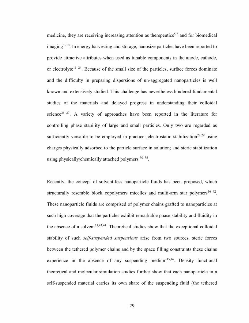
Figure 2.5 (a) Interparticle distance, dp‑p, extracted from the experimental S(q)
(closed symbols) increases with grafting density. A similar trend is observed for
theoretical dp‑p (open symbols). The dashed lines are a guide to the eye. (b) The
height of first peak of S(q) decreases while the (c) S(0) values increases with
increasing grafting density. The experimental values agree well with DFT, and the HS
S(0) values are seen to be higher.

42
attraction between the chains. In contrast to previous observations in ionically grafted
particles,59 where the first peak was found to be weaker for densely grafted systems,
the stronger first peak observed for the present systems even at higher grafting
densities is a consequence of the permanent bond between the chains and the particle
surface. Remarkably, this observation of a weaker second peak has also been observed
in computer simulations of self-suspended particles47. It was postulated that this trend
reflects the fact that chains in covalently grafted hairy nanoparticles are directly
tethered to the surface of the core as opposed to previous studies where electrostatic
interactions between the positively charged core with negatively charged corona52,59
produced stronger S(q) peaks at higher q. The recently developed DFT theory59
predicts polydispersities in core size and grafting densities to fit the experimental data.
Supplementary Figure 2.1 shows the polydispersity in core size, as extracted from
Gaussian fitting of a dilute suspension of the silica nanoparticles. It shows an average
size of 10±2nm, which corresponds to a polydispersity of 20% in core size. On
assuming a polydispersity of 20% in core size, as extracted from Gaussian fitting of
the dilute suspension of silica nanoparticles (Supplementary Figure 2.1), we obtain the
polydispersities in grafting density for different systems from DFT, as reported in
Table 2.1. It can be noted that with increasing Ʃ, or decreasing particle volume
fraction, the polydispersity in grafting density increases. This suggests that the
stronger entropic constraints on the chains at lower volume fraction can be released
more efficiently by introducing more polydispersity in the grafting density.

43
Figure 2.5a) compares the inter-particle distance, dp-p extracted from the first peak
position of S(q) with Ʃ. It can be seen that the inter-particle distance increases with Ʃ
which is not surprising as higher grafting density means that the tethered chains are
more effective in keeping the cores apart, and thus exhibit an effectively higher steric
repulsion as compared to systems with lower grafting density. The experimental dp-p is
found to be roughly consistent with the theoretical estimate of dp-p=2a(0.63/φ)1/3,
where φ is particle volume fraction. A similar trend is manifested in the decrease of
peak height of first peak S(qpeak) (Figure 2.5(b)) with increasing grafting density. Since
densely tethered cores are able to push each other more due to stronger steric repulsion
by the tethered chains, this results in a decrease of correlation amongst the nearest
neighbors as opposed to the sparsely tethered cores where the chains are not able to
stretch out as much and thus the particles are much closer, and the correlation is hence
much enhanced. A potentially even more interesting feature is the increasing S(q)
value at low qÆ0 with the increase in Ʃ, as shown in Figure 2.5(c). A lower S(0) value
at lower grafting densities indicates a more uniform distribution for particles than at
higher grafting densities. The S(0) value for experimental systems was extracted by
performing a quadratic fit for S(q) in the low q region (qa<1.5) and was then
extrapolated to q=0. It is noteworthy, that the S(0) values for experiment are
comparable to theory and are much lower than the hard sphere values, which is strong
evidence of a more uniform distribution for self-suspended particles as opposed to
hard spheres.

44
Figure 2.6 (a) The height of the normalized loss maximum, G″/G″γ→0, increases
with temperature. The inset shows a typical soft glassy response of the material. All
measurements are performed at ω = 10 rad/s. (b) The interparticle distance does not
change with temperature, as observed from the variation of the first peak of structure
factor S(q) with wave vector q at different temperatures for the system. (c) The loss
tangent, tan δ, decreases with temperature. All results are for Σ ≈ 1.18 chains/nm2.
The inset shows a decrease in noise temperature, X, with temperature. The dashed line
is the VFT fit to the data.

45
Next, we performed oscillatory shear experiments at variable shear strain to
investigate the properties of these self-suspended nanoparticles on macroscopic length
scale. The observed material response (inset of Figure 2.6(a)) is typical of a soft
glass43,60,61 wherein the storage modulus G’ dominates the loss modulus G” at low
strain values and on further increasing the strain a prominent maximum is observed in
G” which is now understood to be associated with breaking of the cages neighboring
particles exert on each other.
On investigating the effects of temperature variation (shown in Figure 2.6(a)) we
observe that the loss maximum increases with temperature indicating enhanced
jamming as the height of G” is a reflection of the degree of jamming in the system. As
previously seen in ionically grafted silica nanoparticles50, variation of temperature
does not change the location of the first peak in the structure factor S(q) (Figure 2.6b))
of these covalently grafted systems as well, which implies that change in temperature
does not alter the inter-particle spacing of the cores. This justifies that the increase in
temperature leads to effectively stiffer corona chains resulting in an enhanced corona
inter-penetration, and thus leads to tighter and more jammed cages with increase in
temperature. This trend is further confirmed by decrease in loss tangent, tanδ
(=G”/G’) with increase in temperature (Figure 2.6(c)).
The temperature induced jamming of the system can be quantified using a parameter
referred to as noise temperature, X which has been described in the soft glassy
rheology (SGR) model61,62 as an indication of the amount of energy available for each

46
particle to hop out of its potential energy well in the energy landscape. The noise
temperature can be related to loss tangent as: GS21� X 42,52. The inset of Figure
2.6c) shows a decreasing trend for X with increase in temperature for Ʃ~1.18
chains/nm2, which implies that the particles have lesser energy available for hopping
at higher temperatures, thus leading to jamming of the system with increase in
temperature. Similar behavior with temperature is seen at lower grafting densities of
0.703 and 0.576 chains/nm2 as shown in the supporting information. It is also striking
that the dependence of X on T follows the Vogel-Fulcher-Tammann (VFT) fit63:
)*
exp(TT
BAX�
, where A is the high temperature value of X, B is the activation
energy and T* is the Vogel temperature. All the values are listed in TableI. It is
remarkable that the T* values are close to the melting point of PEG for all the systems,
indicating that the tethered chains play a crucial role in determine the dependence of X
on T. It is also notable that the value of A is always close to unity, indicating that the
colloidal glass transition occurs at high temperature. The thermal jamming observed
here is reminiscent of thermal vitrification that is observed in star polymers.64,65 In
those systems, the star polymers form clusters due to improved solvent quality on
heating. It is rather different from our systems, as the space filling constraint imposed
on the tethered chains prevents any formation of clusters or any inhomogeneties. Also,
the solvent is attached to the core and thus the suspending medium and the suspension
are the same, which excludes any possibility of an improvement in solvent quality.

47
Figure 2.7 (a) G′ in the linear viscoelastic regime decreases with increasing grafting
density while (b) the cage size, R, estimated from G′ and SAXS, and (c) the linear
viscoelastic loss tangent, tan δγ0, increases with increasing grafting density. The lines
are guides for the eye.

48
The effect of variation of grafting density (6) also has a strong effect on the variation
of cage strength. From Figure 2.7a) it is apparent that the value of G’ in the linear
viscoelastic regime decreases with increase in 6. Previous studies have shown that G’
varies as ~kT/r2locD, where rloc is the particle localization length within the cage and D
is the particle diamtere, maximum distance which can be moved by the particle inside
the cage.66,67 However, since in our systems, the cage is determined by the interactions
of the tethered chains while the particles are fixed relative to the chains, the cage size
is determined by the extent of inter-penetration of the chains. So, we assume the
localization length of the cage similar to its maximum size, and thus use G’ ~kT/R3,
where 2R is the cage size. The cage size estimated from G’ is found to be in close
agreement with the cage size obtained from SAXS data as 2R=dp-p-2a (Figure 2.6b)).
The cage size is found to increase with an increase in 6, which implies that the system
becomes less jammed on increasing the grafting density. This behavior is further
confirmed by plotting tanδ as a function of 6 (Figure 2.6c)). The increase in tanδ with
6 indicates un-jamming of the system on adding more chains to the particles, which
further suggests that the cage strength is lowered by an increase in grafting density.
2.5 Conclusion
In summary, we report a facile synthesis route for creating self-suspended
nanoparticles in which each particle permanently carries its own share of liquid in the
form of covalently tethered polymer chains. The materials are found to exhibit
outstanding phase stability in absence of any solvent; they are among the first example

49
of a nanoparticle-polymer composite in which each and every building block is itself a
nanocomposite. On nanometer length scales, the materials show the dominance of
thermodynamically stable conformational modes in the polymer strands compared to
free polymer. At mesoscopic length-scales, we observe that these systems exhibit less
heterogeneity as opposed to their ionic counterparts and have stronger steric repulsions
due to the absence of any electrostatic interactions between the core and corona
conforming to the observations from DFT results. On macroscopic length scales,
dynamic rheology measurements firmly place the materials in the universality class of
soft glasses, but we find that temperature can enhance jamming in the systems, an
unexpected result for a true soft glass where the cage energy is considered
substantially higher than kT.
Acknowledgement
This work was supported by the National Science Foundation, Award No. DMR-
1006323 and by Award No. KUS–C1–018–02, made by King Abdullah University of
Science and Technology (KAUST). Use of the Cornell High Energy Synchrotron
Source was supported by the U.S. DOE under Contract No. DE–AC02–06CH11357.
This work made use of the Cornell Center for Materials Research Shared Facilities,
which are supported through the NSF MRSEC program (DMR-1120296). We thank
Dr. Rajesh Mallavajula for his insights and ideas. We also acknowledge Dr. Ivan
Keresztes for the help with the NMR experiment. We would also like to thank Adithya
Sagar Gurram for his help with DFT calculations.

50
REFERENCES
(1) Einstein, A. Investigations on the Theory of the Brownian Movement. Ann. d.
Phys 1906, 19, 371–381.
(2) Batchelor, G. K. Sedimentation in a Dilute Dispersion of Spheres. J. Fluid
Mech. 1972, 52, 245–268.
(3) Batchelor, G. K. Brownian Diffusion of Particles with Hydrodynamic
Interaction. J. Fluid Mech. 1976, 74, 1–29.
(4) Batchelor, G. K. The Effect of Brownian Motion on the Bulk Stress in a
Suspension of Spherical Particles. J. Fluid Mech. 1977, 83, 97–117.
(5) Davis, M. E.; Chen, Z. G.; Shin, D. M. Nanoparticle Therapeutics: An
Emerging Treatment Modality for Cancer. Nat. Rev. Drug Discov. 2008, 7,
771–782.
(6) Salata, O. V. Applications of Nanoparticles in Biology and Medicine. 2004, 6,
1–6.
(7) Phillips, E.; Penate-Medina, O.; Zanzonico, P. B.; Carvajal, R. D.; Mohan, P.;
Ye, Y.; Humm, J.; Gonen, M.; Kalaigian, H.; Schoder, H.; et al. Clinical
Translation of an Ultrasmall Inorganic Optical-PET Imaging Nanoparticle
Probe. Sci. Transl. Med. 2014, 6, 260ra149–ra260ra149.

51
(8) Kim, Y.; Lobatto, M. E.; Kawahara, T.; Lee Chung, B.; Mieszawska, A. J.;
Sanchez-Gaytan, B. L.; Fay, F.; Senders, M. L.; Calcagno, C.; Becraft, J.; et al.
Probing Nanoparticle Translocation across the Permeable Endothelium in
Experimental Atherosclerosis. Proc. Natl. Acad. Sci. U. S. A. 2014, 111, 1078–
1083.
(9) Rocco, M. a; Kim, J.-Y.; Burns, A.; Kostecki, J.; Doody, A.; Wiesner, U.;
DeLisa, M. P. Site-Specific Labeling of Surface Proteins on Living Cells Using
Genetically Encoded Peptides That Bind Fluorescent Nanoparticle Probes.
Bioconjug. Chem. 2009, 20, 1482–1489.
(10) Bradbury, M. S.; Phillips, E.; Montero, P. H.; Cheal, S. M.; Stambuk, H.;
Durack, J. C.; Sofocleous, C. T.; Meester, R. J. C.; Wiesner, U.; Patel, S.
Clinically-Translated Silica Nanoparticles as Dual-Modality Cancer-Targeted
Probes for Image-Guided Surgery and Interventions. Integr. Biol. (Camb).
2013, 5, 74–86.
(11) Liu, S.; Wang, H.; Imanishi, N.; Zhang, T.; Hirano, a.; Takeda, Y.; Yamamoto,
O.; Yang, J. Effect of Co-Doping Nano-Silica Filler and N-Methyl-N-
Propylpiperidinium Bis(trifluoromethanesulfonyl)imide into Polymer
Electrolyte on Li Dendrite Formation in Li/poly(ethylene Oxide)-
Li(CF3SO2)2N/Li. J. Power Sources 2011, 196, 7681–7686.

52
(12) Lu, Y.; Korf, K.; Kambe, Y.; Tu, Z.; Archer, L. a. Ionic-Liquid-Nanoparticle
Hybrid Electrolytes: Applications in Lithium Metal Batteries. Angew. Chemie
2014, 126, 498–502.
(13) Schaefer, J. L.; Moganty, S. S.; Yanga, D. a.; Archer, L. a. Nanoporous Hybrid
Electrolytes. J. Mater. Chem. 2011, 21, 10094.
(14) Croce, F.; Appetecchi, G. B.; Persi, L.; Scrosati, B. Nanocomposite Polymer
Electrolytes for Lithium Batteries. Nature 1998, 394, 456–458.
(15) Bruce, P. G.; Scrosati, B.; Tarascon, J.-M. Nanomaterials for Rechargeable
Lithium Batteries. Angew. Chem. Int. Ed. Engl. 2008, 47, 2930–2946.
(16) Gurevitch, I.; Buonsanti, R.; Teran, a. a.; Gludovatz, B.; Ritchie, R. O.; Cabana,
J.; Balsara, N. P. Nanocomposites of Titanium Dioxide and Polystyrene-
Poly(ethylene Oxide) Block Copolymer as Solid-State Electrolytes for Lithium
Metal Batteries. J. Electrochem. Soc. 2013, 160, A1611–A1617.
(17) Moganty, S. S.; Srivastava, S.; Lu, Y.; Schaefer, J. L.; Rizvi, S. a.; Archer, L. a.
Ionic Liquid-Tethered Nanoparticle Suspensions: A Novel Class of Ionogels.
Chem. Mater. 2012, 24, 1386–1392.
(18) Chrissopoulou, K.; Andrikopoulos, K. S.; Fotiadou, S.; Bollas, S.;
Karageorgaki, C.; Los, D. C.; Voyiatzis, G. A.; Anastasiadis, S. H. Crystallinity
and Chain Conformation in PEO / Layered Silicate Nanocomposites. 2011,
9710–9722.

53
(19) Zheng, G.; Lee, S. W.; Liang, Z.; Lee, H.-W.; Yan, K.; Yao, H.; Wang, H.; Li,
W.; Chu, S.; Cui, Y. Interconnected Hollow Carbon Nanospheres for Stable
Lithium Metal Anodes. Nat. Nanotechnol. 2014, 9, 618–623.
(20) Liu, S.; Imanishi, N.; Zhang, T.; Hirano, a.; Takeda, Y.; Yamamoto, O.; Yang,
J. Effect of Nano-Silica Filler in Polymer Electrolyte on Li Dendrite Formation
in Li/poly(ethylene oxide)–Li(CF3SO2)2N/Li. J. Power Sources 2010, 195,
6847–6853.
(21) Lu, Y.; Das, S. K.; Moganty, S. S.; Archer, L. a. Ionic Liquid-Nanoparticle
Hybrid Electrolytes and Their Application in Secondary Lithium-Metal
Batteries. Adv. Mater. 2012, 24, 4430–4435.
(22) Baker, G. L.; Colsons, S. Composite Polymer Electrolytes Using Fumed Silica
Fillers : Rheology and Ionic Conductivity. 1994, 2359–2363.
(23) Srivastava, S.; Schaefer, J. L.; Yang, Z.; Tu, Z.; Archer, L. a. 25Th Anniversary
Article: Polymer-Particle Composites: Phase Stability and Applications in
Electrochemical Energy Storage. Adv. Mater. 2014, 26, 201–234.
(24) Agrawal, A.; Choudhury, S.; Archer, L. A. A Highly Conductive, Non-
Flammable Polymer-Nanoparticle Hybrid Electrolyte. RSC Adv. 2015.
DOI: 10.1039/C5RA01031D
(25) Srivastava, S.; Agarwal, P.; Archer, L. a. Tethered Nanoparticle-Polymer
Composites: Phase Stability and Curvature. Langmuir 2012, 28, 6276–6281.

54
(26) Balazs, A. C.; Emrick, T.; Russell, T. P. Nanoparticle Polymer Composites:
Where Two Small Worlds Meet. Science 2006, 314, 1107–1110.
(27) Krishnamoorti, R. Strategies for Dispersing Nanoparticles in Polymers. MRS
Bull. 2007, 32.
(28) Park, B. J.; Vermant, J.; Furst, E. M. Heterogeneity of the Electrostatic
Repulsion between Colloids at the Oil–water Interface. Soft Matter 2010, 6,
5327.
(29) Fritz, G.; Scha, V.; Willenbacher, N.; Wagner, N. J. Electrosteric Stabilization
of Colloidal Dispersions. 2002, 6381–6390.
(30) Zhulina, E. B.; Borisov, O. V; Priamitsyn, V. a. Theory of Steric Stabilization
of Colloid Dispersions by Grafted Polymers. J. Colloid Interface Sci. 1990,
137, 495–511.
(31) Smith, G. D.; Bedrov, D. Dispersing Nanoparticles in a Polymer Matrix: Are
Long, Dense Polymer Tethers Really Necessary? Langmuir 2009, 25, 11239–
11243.
(32) Kalb, J.; Dukes, D.; Kumar, S. K.; Hoy, R. S.; Grest, G. S. End Grafted
Polymer Nanoparticles in a Polymeric Matrix: Effect of Coverage and
Curvature. Soft Matter 2011, 7, 1418.

55
(33) Chevigny, C.; Jestin, J.; Gigmes, D.; Schweins, R.; Di-Cola, E.; Dalmas, F.;
Bertin, D.; Boue, F. “Wet-to-Dry” Conformational Transition of Polymer
Layers Grafted to Nanoparticles in Nanocomposite. Macromolecules 2010, 43,
4833–4837.
(34) Green, D. L.; Mewis, J.; Engineering, C.; Uni, V.; Way, E.; Charlottes, V.
Connecting the Wetting and Rheological Behaviors of Poly ( Dimethylsiloxane
) -Grafted Silica Spheres in Poly ( Dimethylsiloxane ) Melts. 2006, 9546–9553.
(35) Hasegawa, R.; Aoki, Y.; Doi, M. Optimum Graft Density for Dispersing
Particles in Polymer Melts. 1996, 9297, 6656–6662.
(36) Roovers, J.; Paul, L. Z.; Zwan, M. Van Der; Iatrou, H.; Hadjichristidisi, N.
Regular Star Polymers with 64 and 128 Arms. Models for Polymeric Micelles?
Macromolecules 1993, 4324–4331.
(37) Watanabe, H.; Yao, M.; Sato, T.; Osaki, K. Non-Newtonian Flow Behavior of
Diblock Copolymer Micelles : Shear-Thinning in a Nonentangling Matrix.
Macromolecules 1997, 9297, 5905–5912.
(38) Watanabe, H. Nonlinear Rheology of Diblock Copolymer Micellar Dispersion:
A Review of Recent Findings. J. Nonnewton. Fluid Mech. 1999, 82, 315–329.
(39) Sato, T.; Watanabe, H.; Osaki, K. Relaxation of Spherical Micellar Systems of
Styrene - Isoprene Diblock Copolymers . 1 . Linear Viscoelastic and Dielectric
Behavior. Macromolecules 1996, 9297, 3881–3889.

56
(40) Willner, L.; Richter, J. J. D.; Roovers, J.; Z, L.; Festkorperforschung, I.; Gmbh,
F. J. Structural Investigation of Star Polymers in Solution by Small Angle
Neutron Scattering. Macromolecules 1994, 3821–3829.
(41) Adams, J. L.; Graessley, W. W. Rheology and the Microphase Separation
Transition in Styrene-Isoprene. Macromolecules 1994, 6026–6032.
(42) Fetters, L. J.; Andrea, D. K.; J, D. S. P.; Quack, G. F.; Vitus, F. J. Rheological
Behavior of Star-Shaped Polymers. Macromolecules 1993, 647–654.
(43) Agarwal, P.; Qi, H.; Archer, L. a. The Ages in a Self-Suspended Nanoparticle
Liquid. Nano Lett. 2010, 10, 111–115.
(44) Fernandes, N. J.; Akbarzadeh, J.; Peterlik, H.; Giannelis, E. P. Terms of Use
Synthesis and Properties of Highly Dispersed Ionic Silica À Poly ( Ethylene
Oxide ) Nanohybrids. 2013, 1265–1271.
(45) Yu, H.-Y.; Koch, D. L. Structure of Solvent-Free Nanoparticle-Organic Hybrid
Materials. Langmuir 2010, 26, 16801–16811.
(46) Chremos, A.; Panagiotopoulos, A. Z.; Yu, H.-Y.; Koch, D. L. Structure of
Solvent-Free Grafted Nanoparticles: Molecular Dynamics and Density-
Functional Theory. J. Chem. Phys. 2011, 135, 114901.

57
(47) Hong, B.; Chremos, A.; Panagiotopoulos, A. Z. Simulations of the Structure
and Dynamics of Nanoparticle-Based Ionic Liquids. Faraday Discuss. 2012,
154, 29.
(48) Chremos, A.; Panagiotopoulos, A. Z.; Koch, D. L. Dynamics of Solvent-Free
Grafted Nanoparticles. J. Chem. Phys. 2012, 136, 044902.
(49) Goyal, S.; Escobedo, F. a. Structure and Transport Properties of Polymer
Grafted Nanoparticles. J. Chem. Phys. 2011, 135, 184902.
(50) Agarwal, P.; Srivastava, S.; Archer, L. a. Thermal Jamming of a Colloidal
Glass. Phys. Rev. Lett. 2011, 107, 268302.
(51) Jespersen, M. L.; Mirau, P. A.; Meerwall, E. Von; Vaia, R. A.; Rodriguez, R.;
Ќ, E. P. G. Canopy Dynamics in Nanoscale Ionic Materials. 2010, 4, 3735–
3742.
(52) Fernandes, N. J.; Wallin, T. J.; Vaia, R. a.; Koerner, H.; Giannelis, E. P.
Nanoscale Ionic Materials. Chem. Mater. 2014, 26, 84–96.
(53) Coleman, M. M.; Skrovanek, D. J.; Hu, J.; Painter, P. C. Hydrogen Bonding in
Polymer Blends. 1. FTIR Studies of Urethane-Ether Blends. Macromolecules
1988, 21, 59–65.
(54) Kim, S. a; Archer, L. a. Hierarchical Structure in Semicrystalline Polymers
Tethered to Nanospheres. Macromolecules 2014, 47, 687–694.

58
(55) Agarwal, P.; Kim, S. a.; Archer, L. a. Crowded, Confined, and Frustrated:
Dynamics of Molecules Tethered to Nanoparticles. Phys. Rev. Lett. 2012, 109,
258301.
(56) Matsuura, H.; Fukuhara, K. Vibrational Spectroscopic Studies of Conformation
of Poly ( oxyethy1ene ). 11 . Conformation- Spectrum Correlations. 1986, 24,
1383–1400.
(57) Deng, Y.; Dixon, J. B.; White, G. N. Bonding Mechanisms and Conformation
of Poly(ethylene Oxide)-Based Surfactants in Interlayer of Smectite. Colloid
Polym. Sci. 2005, 284, 347–356.
(58) Glatter, O.; Kratky, O. Small Angle X-Ray Scattering; United Sta.; Academic
Press: New York, 1982.
(59) Yu, H.-Y.; Srivastava, S.; Archer, L. a; Koch, D. L. Structure Factor of Blends
of Solvent-Free Nanoparticle-Organic Hybrid Materials: Density-Functional
Theory and Small Angle X-Ray Scattering. Soft Matter 2014, 10, 9120–9135.
(60) Mason, T. G.; Weitz, D. A. Linear Viscoelasticity of Colloidal Hard SPhere
Suspensions near the Glass Transition. 1995, 75, 2770–2773.
(61) Sollich, P.; Lequeux, F.; Hébraud, P.; Cates, M. Rheology of Soft Glassy
Materials. Phys. Rev. Lett. 1997, 78, 2020–2023.

59
(62) Sollich, P. Rheological Constitutive Equation for a Model of Soft Glassy
Materials. Phys. Rev. E 1998, 58, 738–759.
(63) Angell, C. a.; Ngai, K. L.; McKenna, G. B.; McMillan, P. F.; Martin, S. W.
Relaxation in Glassforming Liquids and Amorphous Solids. J. Appl. Phys.
2000, 88, 3113.
(64) Kapnistos, M.; Vlassopoulos, D.; Fytas, G.; Mortensen, K.; Fleischer, G.;
Roovers, J. Reversible Thermal Gelation in Soft Spheres. Phys. Rev. Lett. 2000,
85, 4072–4075.
(65) Loppinet, B.; Stiakakis, E.; Vlassopoulos, D.; Fytas, G.; Roovers, J. Reversible
Thermal Gelation in Star Polymers : An Alternative Route to Jamming of Soft
Matter. 2001, 8216–8223.
(66) Mason, T. G. Estimating the Viscoelastic Moduli of Complex Fluids Using the
Generalized Stokes-Einstein Equation. Rheol. Acta 2000, 39, 371–378.
(67) Shah, S. a.; Chen, Y.-L.; Schweizer, K. S.; Zukoski, C. F. Viscoelasticity and
Rheology of Depletion Flocculated Gels and Fluids. J. Chem. Phys. 2003, 119,
8747.

60
APPENDIX
Supplementary Information for Chapter 2
Figures-
Supplementary Figure 2.2. a) HSQC 1H-
13C in CDCl
3 at 25°C. b) HMBC 1H-13C in
CDCl3 at 25°C

61
Supplementary Figure 2.1. Size distribution of Silica nanoparticles as determined from SAXS analysis. The solid line denoted Gaussian fits to the data. Inset: Experimental scattering intensity for Silica nanoparticles(red dots) and the fit to data (Black line).
a)
b)

62
a)
b)
Supplementary Figure 2.3. Comparison of centrifuge and ultra-centrifuge for a) covalently grafted nanoparticles and b) Ionically grafted nanoparticles. It can be observed that the resultant weight % for the covalent system is the same from both the methods while for the ionic system the weight fraction of silica goes on decreasing when ultra-centrifuged. c) Amplitude sweep measurement of the covalently grafted sample for normal centrifuge and after ultra-centrifuge. The two measurements can be seen to overlap.
c)

63
Supplementary Figure 2.4 Gaussian fitting of the FT-IR peaks for tethered PEO chains of grafting density, Ʃ~1.03 chains/nm2.

64
Supplementary Figure 2.5. Variation of intensity(I(q)) as measured from SAXS experiments with q at different grafting densities.

65
Supplementary Figure 2.6 a) Variation of normalised loss modulus G”/G”γÆ0 and b) tan(δ) with strain amplitude at different temperatures. All the measurements are performed at ω=10 rad/s c) Similar trends are seen in noise temperature X variation with temperature. The results are for system with Ʃ~0.703 chains/nm2
c)
b) a)

66
Supplementary Figure 2.7 a) Variation of normalised loss modulus G”/G”γÆ0 and b) tan(δ) with strain amplitude at different temperatures and at ω=10rad/s c) Similar trends are seen in noise temperature X variation with temperature. The results are for system with Ʃ~0.576 chains/nm2
c)
a) b)

67
a) b)
c)
Supplementary Figure 2.8 Frequency sweep measurements at γ=0.1% at different temperatures for a) Ʃ~1.18 chains/nm2 b) Ʃ~0.703chains/nm2 and c) Ʃ~0.576 chains/nm2. Storage Modulus, G’ (closed symbols) is found to be always greater than the loss modulus, G” (open symbols)

68

69
CHAPTER 3
A HIGHLY CONDUCTIVE, NON-FLAMMABLE POLYMER-
NANOPARTICLE HYBRID ELECTROLYTE

70
3.1 Abstract
We report on physical properties of lithium-ion conducting nanoparticle-polymer
hybrid electrolytes created by dispersing bidisperse mixtures of polyethylene glycol
(PEG)-functionalized silica nanoparticles in an aprotic liquid host. At high particle
contents, we find that the ionic conductivity is a non-monotonic function of the
fraction of larger particles xL in the mixtures, and that for the nearly symmetric case
xL≈ 0.5 (i.e. equal volume fraction of small and large particles), the room temperature
ionic conductivity is nearly ten-times larger than in similar nanoparticle hybrid
electrolytes comprised of the pure small or large particle components used in the
mixtures. Complementary behaviors are seen in the activation energy for ion
migration and effective tortuosity of the electrolytes, which both exhibit minima near
xL≈ 0.5. Characterization of the electrolytes by dynamic rheology reveals that the
maximum conductivity coincides with a distinct transition in soft glassy properties
from a jammed to partially jammed and back to jammed state, as the fraction of large
particles is increased from 0 to 1; indicating that the conductivity enhancement arises
from purely entropic loss of correlation between nanoparticle centers arising from
particle size dispersity. As a consequence of these features, we show that it is possible
to create hybrid electrolytes with 1 MPa elastic moduli and 1 mS/cm ionic
conductivities at room temperature using common aprotic liquid media as the
electrolyte solvent. Remarkably, we also find that even in highly flammable liquid
media, the bidisperse nanoparticle hybrid electrolytes can be formulated to exhibit low
or no flammability without compromising their favorable ionic conductivity and
mechanical properties.

71
3.2 Introduction
Significant amount of research has been devoted towards improving the portability,
power, lifetime and safety of secondary rechargeable batteries with exclusive focus on
battery electrolytes and ion conducting membranes1–6. Polymer nanocomposite is a
special class of such an electrolyte that has created new platforms to mitigate the
issues associated with conventional flammable liquid electrolytes4–8. These
nanocomposite electrolytes have improved the safety as well as portability of batteries
and have prevented electrolyte leakage, thus eliminating the need of a physical
separator9–15. The inorganic particles in polymer electrolytes affect the ion transport
mainly as passive filler and sometimes as active filler9. As a passive filler, they act as
plasticizers for the polymers preventing crystallization, thus speeding up the segmental
dynamics of polymer host and enhancing the ion transport9,12,14–16. However, an
optimum nanoparticle loading is required to ensure a well-dispersed state of the
particles, such that the ion transport pathway is not disrupted due to high particle
concentration. Active fillers directly participate in the ion transfer process either by
providing additional cations/anions or by surface reaction with mobile ions. They are
shown to improve the cation transference number that ultimately results in significant
increment in the coulombic stability of the batteries9,11,12,15,17,18.
Perhaps, the greatest benefit of these nanocomposite electrolytes is their integration
towards higher mechanical stability. It has been previously reported that a high
modulus electrolyte can be effective in preventing dendrite-induced short circuit in a
Lithium metal battery19–25. Nanocomposite based batteries have shown encouraging

72
results in this regard26–28,16. Although all the above properties are of relevant interest
for application in rechargeable battery industry, low ambient conductivity and high
interfacial resistance hinder the practicality of the nanocomposite electrolytes9,26,29,30.
Weston and Steele31 were the first to make improvements towards developing a
decently ion conducting and highly mechanical stable electrolyte by adding ceramic
fillers in low volume fractions to polyethylene oxide polymer. However, achieving
practical conductivity at high particle loadings, where the mechanical strength is
maximized, has been a tough task for over a decade.
Recent studies on hybrid electrolytes based on polymer-tethered nanoparticles have
shown a significant promise towards this step32–34. These hybrid electrolytes based on
hairy nanoparticles have good mechanical and electrochemical properties, and at the
same time they provide enough room for nano-engineering to improve the current
state of art even further. The polymer-grafted nanoparticles have been shown to
exhibit interesting physical properties like viscoelasticity35, thermal jamming36, and
star polymer like relaxation37. Previously, studies on binary mixture of star polymers
have gained significant attention by showing that addition of smaller star polymers to
bigger ones leads to a transition from glassy state to liquid state38,39. Similar studies on
the self-suspended binary mixtures of these hairy nanoparticles have demonstrated that
addition of either small or bigger particles leads to un-jamming of the system40.
Currently, we focus on this jamming transition observed in binary hairy nanoparticles
in the context of an electrolyte and try to utilize it to build a better battery.

73
In this article we report on ionic conductivity, mechanical properties, and structure of
hybrid electrolytes comprised of a bidisperse blend of SiO2-PEG hairy nanoparticles
dispersed in propylene carbonate (PC). The study focuses on silica particles with
diameters of 10 nm and 25 nm covalently functionalized with PEG oligomers. Our
specific interest is in understanding the effect of both the total particle volume
fraction, Φ, and relative volume fraction of the bigger particles xL – at a fixed Φ – on
suspension structure and physical properties. We find that the additional degree of
freedom provided by xL allows the structure and transport properties of polymer-
nanoparticle hybrid electrolytes to be tuned in novel ways to achieve both high ionic
conductivity and good mechanical performance. To our knowledge, this is the first
study to systematically investigate the effect of particle size dispersity on conductivity
of nanoparticle-polymer hybrid electrolytes.
3.3 Materials and Methods
3.3.1 Synthesis
Silica nanoparticles (Ludox, SM-30 and TM-50; Sigma Aldrich) with diameters of
10nm and 25nm, respectively, were grafted by covalent attachment of a
trimethoxysilane functionalized polyethylene glycol methyl ether (PEG,
MW~500g/mol, Gelest chemicals) in aqueous solution using a previously reported
silane chemistry41,42 (see schematic in Figure 3.1(a)). The grafting densities were
computed from analysis of the residual inorganic content using thermal gravimetric
analysis (TGA) to be Σ~1.3 chains/nm2 and Σ~1.5 chains/nm2 for 10nm and 25nm
particles, respectively. Following synthesis, the hairy particles were purified using a

74
two-step process, first by dialysis using a snake skin membrane to remove any
dissolved salts along with unattached free PEG chains; and second by repeated
centrifugation at 8500 rpm for 10 minutes using a chloroform(solvent)-hexane(non-
solvent) mixture to completely remove any remaining unattached PEG oligomers. The
particles were then subsequently dried in convection oven at 55°C overnight and at
least for 12hrs under high vacuum. The dried sample was quickly transferred to Argon
filled glove box for storage and subsequent modification. Electrolytes were prepared
inside the glove box by suspending the hairy nanoparticles in the electrolyte solvent
propylene carbonate (PC, Sigma Aldrich) at various core volume fractions, Φ ranging
from 0.1 to 0.5. For each Φ, the relative fraction of bigger particles with respect to the
overall particle volume fraction, i.e. ΦL/Φ=xL, in the SiO2-PEG/PC suspensions was
varied. The resulting solution of hybrid nanoparticles in PC was doped with
bis(trifluoromethanesulfone imide) (LiTFSi, Sigma Aldrich) salt to create SiO2-
PEG/PC hybrid electrolytes containing 1M LiTFSI based on the total organic content
(i.e. PEG corona and PC electrolyte solvent).
3.3.2 Characterization
The particle weight fraction in the SiO2-PEG/PC-LiTFSi hybrid electrolytes was
determined from thermal gravimetric analysis (TGA) by heating the sample at 10
°C/min to 600 °C. The structure and dispersion state of the nanoparticles was
characterized by angle-resolved Small Angle X-ray Scattering (SAXS) measurements
at Station D1 of Cornell High Energy Synchrotron Source (CHESS) using a point

75
collimated X-ray beam. All studied materials were smeared on a sample cell and the
measurements were performed at 30 °C.
Dynamic rheological properties were studied using frequency- and strain-dependent
oscillatory shear measurements at 30 °C on a MCR 301 rheometer outfitted with
10mm diameter, 2° cone and plate fixtures. The frequency sweep measurements were
performed at a low strain, γ=0.05%, which is within the linear viscoelastic regime for
the materials. The strain-dependent oscillatory shear measurements were performed at
a fixed angular frequency of ω=10rad/s.
3.3.3 Electrochemical measurements
The ionic conductivity of the SiO2-PEG/PC-LiTFSI hybrid electrolytes was measured
as a function of temperature, ranging from 0°C to 105°C, using a Novocontrol
Broadband Dielectric spectrometer. For each temperature, the frequency was varied
from 0.1-3x10⁶ Hz. The DC conductivity at each temperature was obtained from the
plot of real part of the conductivity with frequency using the procedure described by
Jonscher43. The Re[conductivity] can be expressed as σ’(ω) = σDC+Aωs; where A is a
constant. The DC conductivity can thus be estimated from the plateau value of the plot
between Re[conductivity] and ω.
3.3.4 Characterizing Flammability

76
The flammability of electrolytes containing the hairy SiO2-PEG nanoparticles was
studied by suspending the particles in a more flammable electrolyte mixture, ethylene
carbonate/diethyl carbonate (EC: DEC, Sigma Aldrich). This approach was necessary

77
Figure 3.1 Physical Characterization – (a) schematic of hairy nanoparticle
synthesis. (b) Transmission Electron Micrograph (TEM) image of binary hairy
nanoparticle composite with xL . 0.5. (c) Intensity (I(q)) as a function of wave vector
(q) for xL . 0.5 at different F, obtained from SAXS measurements. (d) Pictorial
representation of a battery with binary hairy nanoparticle composite electrolyte.
because the PC solvent used for the other studies is flammable only at very high
temperatures. The samples used for this component of the study were doped with 1M
of Lithium hexafluorophosphate (LiPF6, Sigma Aldrich). 0.2g of SiO2-
PEG/EC:DEC/LiPF6 hybrid electrolytes at xL= 0.5 and various Φ were transferred to
Aluminum pans. Material flammability was studied by igniting each electrolyte
specimen with butane torch lighter and recording images at the time of ignition, 4s
after ignition, and at the time the flame self-extinguished.
3.4 Results and Discussion
Figure 3.1(b) is a Transmission electron micrograph (TEM) of a SiO2-PEG/PC hybrid
electrolyte with Φ=0.5 and xL=0.5. The particles are observed to be quite well
dispersed in the PC host. Figure 3.1(c) reports the wavenumber (q)-dependent
scattering intensity (I(q)) for SiO2-PEG/PC hybrid electrolyte obtained using SAXS
measurements. The results are reported for a fixed value of xL=0.5 at different Φ. It is
evident that at any Φ, in the low q region, I(q) is at best a very weak function of q,
whereas in the high q region, I(q) varies as q-4. Both observations are characteristic of
un-aggregated well-dispersed spherical nanoparticles confirming the good dispersion
state of the materials inferred from the small-area TEM measurements44,45.

78
Figure 3.2 shows the temperature dependent DC conductivity of SiO2-PEG/PC-
LiTFSi hybrid electrolytes at various particle volume fractions (Φ) and for a range of
xL values (0≤ xL ≤1). The data is well described by the Vogel-Fulcher-Thamann
(VFT) temperature dependent conductivity, S(T) = Aexp(-Ea/k(T-T0)), over much of
Figure 3.2 Electrochemical properties – conductivity as a function of inverse of
temperature for different core volume fraction (F) at various fractions of bigger
nanoparticles in the binary composite electrolyte indicated by xL, as, (a) xL = 0; (b)
xL = 0.25; (c) xL = 0.5; (d) xL = 0.75; (e) xL = 1.

79
the temperature range and for all the electrolytes studied. Here the prefactor A, with
units S/cm, is proportional to the number of mobile ions present in the electrolyte, Ea
is the activation energy for ion mobility in kJ/mole, k is the gas constant in kJ/mole-K,
and To is the empirical reference Temperature in K.46 The fact that conductivity for
all electrolyte compositions studied are well described by the VFT relation over the
entire range of temperature implies that there is no melting or crystallization transition,
and that there is no phase separation.
In order to understand the effect of particle size dispersity on ionic conductivity, the
DC conductivity measured at a fixed temperature T=30C is plotted as a function of xL
at different Φ, in Figure 3.3(a). It can be observed that at Φ =0.1 and 0.2, the
conductivity does not vary much with changes in xL. However, for Φ≥0.3
conductivity for the bidisperse SiO2-PEG/PC-LiTFSi hybrid electrolytes is noticeably
higher than the conductivity of hybrid electrolytes comprised of the pure small (xL=0)
or big (xL=1) SiO2-PEG hairy nanoparticles. This effect is most pronounced at Φ=0.5,
where a clear maximum is seen near xL=0.5. The conductivity is also plotted as a
function of overall particle volume fraction for different xL values in Supplementary
Figure 3.1. There is a greater drop in the conductivity on increasing the particle
volume fraction for pure small (xL=0) and big (xL=1) SiO2-PEG/PC-LiTFSi hybrid
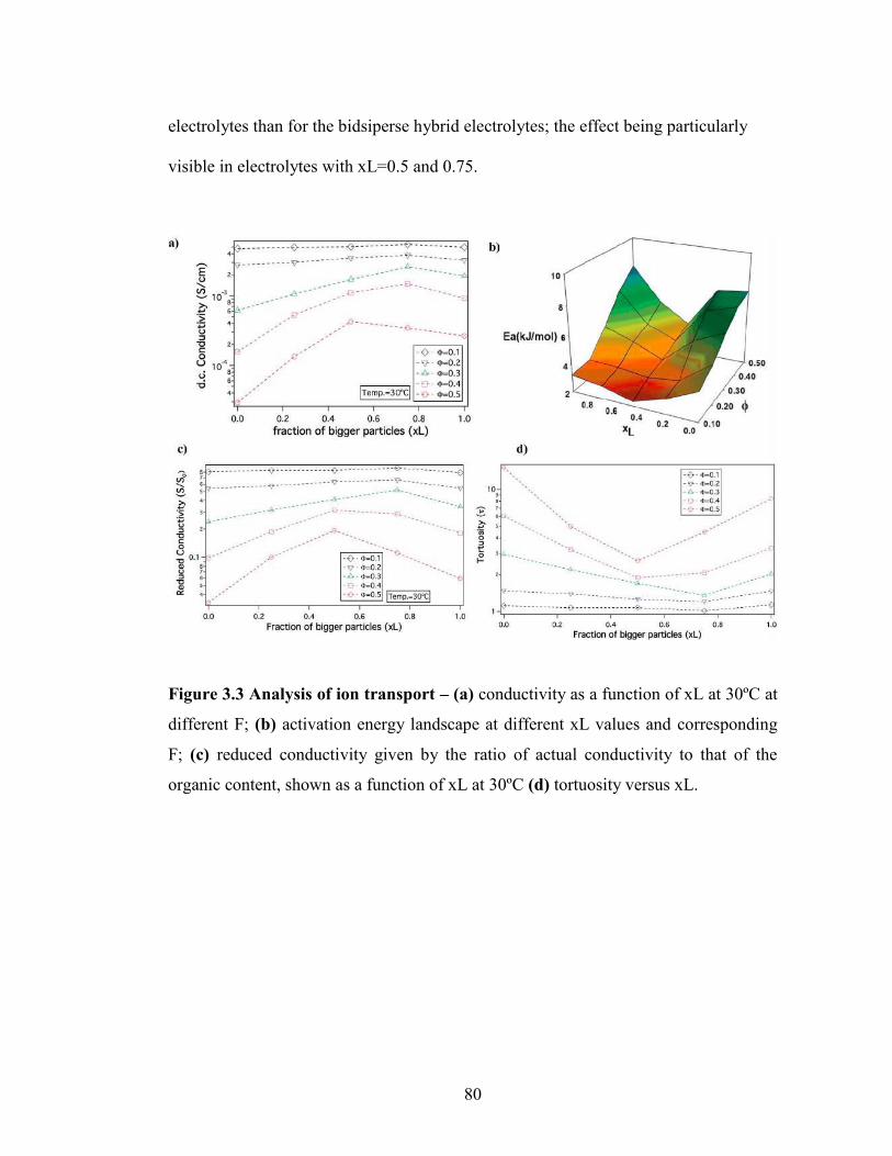
80
electrolytes than for the bidsiperse hybrid electrolytes; the effect being particularly
visible in electrolytes with xL=0.5 and 0.75.
Figure 3.3 Analysis of ion transport – (a) conductivity as a function of xL at 30ºC at
different F; (b) activation energy landscape at different xL values and corresponding
F; (c) reduced conductivity given by the ratio of actual conductivity to that of the
organic content, shown as a function of xL at 30ºC (d) tortuosity versus xL.

81
Activation energies computed from the VFT fits of temperature-dependent
conductivity provides additional insights about the nature of ion transfer processes in
electrolytes. It is known that for electrolytes with higher activation energy there is a
significant change in conductivity associated with temperature, which is correlated
with more practical risks, such as thermal runaway and fire in cells in which there are
exothermic side reactions47. Figure 3.3(b) reports the activation energy landscape
obtained from VFT fits at different Φ and xL. It is seen that for high Φ the activation
energy is greatest for the pure small (xL= 0) or pure big (xL=1) hybrid electrolyte and
that it is minimum near xL ≈ 0.5 (see also, Table ST1 in Supplementary Information).
Consistent with the conductivity data, the effect becomes weaker as the overall
particle volume fraction, Φ, in the electrolytes is reduced. Thus, the bidisperse system
of nanocomposite electrolytes can find wide applications as electrolytes that can be
used at ambient temperatures, while sustaining sudden thermal shocks.
We hypothesize that the observed enhancement in conductivity in bidisperse SiO2-
PEG/PC-LiTFSI hybrid electrolytes at high Φ and xL≈0.5 may arise due to reduced
correlation between particle-centers in the bidisperse materials. In particular at the
high particle volume fractions, where bidispersity has the most noticeable effect on
conductivity and activation energy, the positions of SiO2-PEG nanospheres in a
monodisperse suspension are more correlated than in the bidisperse case. The tethered
PEG corona chains are hence more crowed and confined in electrolytes containing
either pure small or pure large SiO2-PEG particles. Such crowding of surface grafted
chains has already been reported to lead to dramatically slower chain reorientation

82
dynamics for cis-1,4-polyisoprene tethered to SiO2.35 The motion of ions mediated by
the confined PEG chains would therefore be expected to be correspondingly impaired
and sluggish, which is consistent with the higher activation energy. In contrast, for a
bidisperse suspension of SiO2-PEG nanospheres, neighboring particles exert weaker
constraints on each other because of the size dispersity. In other words, at high particle
loadings, the system is less jammed due to the heterogeneities introduced by addition
of a different sized species40,48,49, thus loosening the packing of particles and reducing
the confinement on tethered PEG chains, increasing their mobility and lowering the
activation energy. This freedom would in turn increase the rate at which ions migrate
in the electrolyte, reflected in a higher ionic conductivity. This hypothesis can also
account for the weaker of particle size dispersity at lower Φ where the tethered PEG
chains are not confined and ion motion is controlled more in coordination with the
mobile PC phase.
Since, the organic phase in the SiO2-PEG/PC-LiTFSi hybrid electrolytes is comprised
of both PC and tethered PEG chains, it is useful to resolve the relative content of PEG
and PC in different electrolytes to better understand the effect of bidispersity of the
nanocores on electrolyte properties. The conductivity of PC/PEG-LITFSi liquid
electrolyte mixtures was measured as a function of composition and the results are
reported in Supplementary Figure 3.2. A straight-line fit of the data allows us to
determine how the content of PC/PEG influences ionic conductivity in the absence of
particles. Using this knowledge, the conductivity contribution (So) attributable to the
organic content for each electrolyte shown in Figure 3.3(a) can be recovered. The

83
relative PC content in each sample is tabulated in Supplementary Table 1. In order to
isolate the contribution of the nanocores, we plot the reduced conductivity as S/So
versus the fraction of bigger particles (xL) in Figure 3.3(c). The effect of particle size
dispersity is now more profound, but again the maximum is most readily apparent for
hybrids with the highest Φ and the maximum is clear. Hence, we conclude that the
idea of unjamming a high-volume fraction nanoparticle hybrid electrolyte by
introducing bidispersity is not a function of the chemistry of the electrolyte solvent,
making the concept a potentially powerful tool in other fields, such as ion exchange
chromatography, desalination, and electroplating, where ion transport through
complex media is relevant.
To understand the nature of the inter-particle spaces in the SiO2-PEG/PC hybrid
electrolytes, we look at the trends in ‘tortuosity’ of these materials, as previously
proposed by Carman50. The conductivity of an electrolyte is a direct reflection of the
tortuous nature of the conducting phase, where, tortuosity is defined as the ratio
between the actual distance covered by the ions to travel across the bulk and the
shortest distance between the two points. In the context of electrolytes, the
conductivity of a neat electrolyte is suppressed by the addition of nanoparticles or
other non-conducting entities depending upon the resulting porosity, which is
equivalent to the volume fraction of the conductive phase in a suspension electrolyte.
The experimental conductivity, S, is lower than that obtained empirically, So(1- Φ),
this discrepancy is quantified using the term effective tortuosity51. Figure 3.3(d)
reports tortuosity as a function of xL for different volume fractions for the binary hairy

84
nanoparticle electrolytes. It is seen that for low volume fractions, there is little change
across the range of xL, and the tortuosity values remain close to unity. This is
consistent with intuition that, at low particle volume fraction, the nature of the
conducting pathway across the electrolyte is almost same as for the particle-free
electrolyte and size dispersity of the particulate phase has no obvious effect on
conductivity. On increasing the particle volume fraction, the tortuosity of the pure
small or pure big SiO2-PEG/PC-LiTFSI electrolyte becomes greater than 10, however
the bidisperse hybrid electrolytes are seen to have substantially lower effective
tortuosity. This behavior can be attributed to the unjamming of densely packed SiO2-
PEG nanoparticles, facilitating nearly unimpeded transport of ions in the electrolyte.
Although empirical models for tortuosity for different shaped randomly spaced
particles exist,51–55 such models do not yet exist for the surface-functionalized particles
used in this study, making it difficult at the present time to understand the significance
of the experimentally determined values for tortuosity.
The changes in ionic conductivity are associated with important changes in
mechanical properties of the electrolytes. It can be seen from Figure 3.4(a) that for a
given xL value, on changing Φ from 0.2 to 0.5, the system undergoes a well-studied
transition from a viscoelastic liquid in which the loss modulus, G”, is larger than the
storage modulus G’, to a soft glass, characterized by G’ >> G” at low shear strains,
and the tell tale maximum in G” at higher strains associated with yielding and flow
(G”> G’) of the material56,57. In particular, at low Φ and for xL =0 or 1, G” > G’,
indicating the electrolytes exhibit liquid-like behavior; remarkably, even under these

85
Figure 3.4: Rheological properties- a) Evolution of storage modulus, G’ (closed
symbol) and loss modulus, G” (open symbol) as a function of amplitude strain, γ with
particle volume fraction, Φ at xL =0,0.5 and 1 on going from left to right. b) Variation
of Loss Tangent, tan(δ)= G”/ G’ obtained at γÆ0 as a function of xL at Φ=0.5. Since
tan(δ) is the ratio of loss modulus to storage modulus, the higher the loss tangent the
more fluid-like or un-jammed the system is. It can be observed that addition of either
small or big particles leads to increase in un-jamming of the particles as compared to
the pure species. c) Storage modulus at γÆ0 varying as a function of Φ at different xL
values. It can be seen that at high Φ, the modulus values are extremely high, more than
106.

86
conditions the bidisperse mixture with xL=0.5 shows soft glassy behavior. In
concentrated particulate suspensions, soft glassy rheology is understood to result from
crowding and trapping of particles in cages formed due to the presence of neighboring
particles. Upon increasing the shear strain, these cages break producing the burst of
dissipated energy as particles move relative to each other, which manifests as a
maximum in G”.58,59 This implies that in such suspensions high shear strains can
transform a jammed material to a less solid-like, processable form; removal of the
strain causes the cage structure to reform and the solid-like jammed state is restored.
The degree of jamming in a soft glassy material can be quantified using the value of
its loss tangent (tanδ=G”/G’), measured at low stains in the linear viscoelastic regime
of oscillatory shear measurements. Figure 3.4(b) shows tanδ value as a function of xL,
it is seen that addition of either the bigger or smaller particles to their pure cohorts
leads to an increase in tanδ; implying that introduction of heterogeneity leads to less
jamming of the system. Remarkably, at Φ = 0.5, where the electrolyte exhibits soft
glassy rheology over the entire range of xL, tanδ exhibits a clear maximum near
xL=0.5, i.e. exactly where the maximum in ionic conductivity and minimum in
activation energy for the electrolytes is observed. This finding succinctly shows that
the enhanced conductivity for the bidisperse SiO2-PEG/PC hybrid electrolytes is a
result of reduced jamming. Figure 3.4(c) shows the viscoelastic storage modulus (G’)
of these electrolytes as a function of volume fraction for various xL. At high particle
loading, these electrolytes display G’ values around 5MPa (Supplementary Table 3.1),

87
which is only modestly lower than the modulus of hybrid electrolytes created using the
pure small or pure large particles at Φ = 0.5.
The favorable ionic conductivity and mechanical properties of these bidisperse SiO2-
PEG/PC-LiTFSI hybrid electrolytes at relatively high nanoparticle concentrations is
already attractive for the application related investigations outlined in the introduction.
Since silica and PEG are both non- or poorly-flammable materials, it is possible that at
the high particle loadings where size dispersity has the greatest effect on conductivity
and rheology of the electrolytes, it may also have a positive effect on their safety. To
explore this aspect of the materials, we briefly studied their flammability using a
previously disclosed protocol.13 The experiments are complicated by the fact that
propylene carbonate, the electrolyte solvent used in the study so far, is only flammable
at very high temperatures. In order to correctly assess the role of particles on
flammability, we have created similar nanoparticle hybrid electrolytes in a more
flammable electrolyte solvent (EC: DEC with 1M LiPF6). Figure 3.5 reports the
results from these experiments in the form of snapshots of an electrolyte with xL=0.5,
with varying nanoparticle contents at different times following ignition. Figure 3.5(a)
shows the physical appearance of the electrolyte specimen at each volume fraction
before ignition. Figure 3.5(b) shows the same materials at the time of ignition, i.e. at
t=0. It can be seen that the electrolyte specimen with Φ=0.4 initially catches fire, it is
extinguished within one second of ignition; whereas the specimen with Φ=0.5 is
highly fire resistant. At the same time, the neat electrolyte without any particle or the
samples with lower core volume fractions burn when ignited, as also seen in Figure

88
Figure 3.5: Flammability Test- Electrolyte samples with different particle volume
fraction a) before ignition i.e. t<0. b) At ignition time i.e. t=0 c) after ignition i.e. at
t=4s d) At the extinguishing time. The binary electrolyte sample used here
corresponds to xL=0.5.

89
3.5(c). Figure 3.5(d) marks the time required for the fire to completely extinguish.
Among the flammable samples, the particle-free electrolyte burns out the quickest,
while the electrolytes with Φ=0.3 take the longest to completely extinguish; implying
that the degree of flammability decreases for higher volume fractions. The bidisperse
hybrid electrolytes with Φ=0.4 and 0.5 therefore appear to be good candidates for
future applications-oriented studies.
3.5 Conclusion
In summary, we have synthesized nanoparticle hybrid electrolytes based on bidisperse
mixtures of PEG-functionalized silica nanoparticles in aprotic electrolyte solvents.
The nanoparticles are found to be well dispersed and un-aggregated in their liquid
hosts, even at high volume fractions. The conductivity of electrolytes containing
nanoparticles with a bimodal size distribution is found to exhibit a pronounced
maximum when the volume fraction of small and large particles is the same. This
observation is attributed to the ability of large/small particles in a concentrated
suspension of the opposite counterpart to produce disordering of the suspension by
lowering correlation among the polydisperse particles. The tortuosity as well as
activation energy values obtained from the measured conductivity show pronounced
minima that correlate with the maximum conductivity, lending support to the idea that
loose packing of the cores in a binary suspension is responsible for the observed
enhancement in conductivity. Oscillatory shear rheology measurements show that the
hybrid electrolytes transits from a jammed state to relatively unjammed and back to a
jammed state when the fraction of bigger particles in the mixture is increased from 0

90
to 1. At high nanoparticle volume contents, where the effect of particle size dispersity
on conductivity is greatest, little changes are seen in the elastic modulus of the
materials. In particular, it is possible to create nanoparticle hybrid electrolytes with 5
MPa mechanical modulus and 1 mS/cm level ionic conductivity at room temperature.
Preliminary studies of flammability show that even if the electrolyte solvent used in
such bidisperse nanoparticle hybrid electrolytes is a high-flammability aprotic liquid,
the electrolytes can be formulated to exhibit low flammability. Thus, we conclude that
nanoparticle hybrid electrolytes created using bidisperse mixtures of PEG-
functionalized particles in conventional aprotic liquids provide an attractive platform
for tuning multiple properties of contemporary interest for applications.

91
REFERENCES
(1) Dunn, B.; Kamath, H.; Tarascon, J.-M. Electrical Energy Storage for the Grid:
A Battery of Choices. Science 2011, 334, 928–935.
(2) Yang, P.; Tarascon, J.-M. Towards Systems Materials Engineering. Nat.
Mater. 2012, 11, 560–563.
(3) Bouchet, R.; Maria, S.; Meziane, R.; Aboulaich, A.; Lienafa, L.; Bonnet, J.;
Phan, T. N. T.; Bertin, D.; Gigmes, D.; Devaux, D.; et al. Efficient Electrolytes for
Lithium-Metal Batteries. Nat. Mater. 2013, 12, 452–457.
(4) Tarascon, J. M.; Armand, M. Issues and Challenges Facing Rechargeable
Lithium Batteries. Nature 2001, 414, 359–367.
(5) Dresselhaus, M. S.; Thomas, I. L. Alternative Energy Technologies. Nature
2001, 414, 332–337.
(6) Armand, M.; Tarascon, J.-M. Building Better Batteries. Nature 2008, 451,
652–657.
(7) Zhou, M.; Cai, T.; Pu, F.; Chen, H.; Wang, Z.; Zhang, H.; Guan, S.
Graphene/carbon-Coated Si Nanoparticle Hybrids as High-Performance Anode
Materials for Li-Ion Batteries. ACS Appl. Mater. Interfaces 2013, 5, 3449–3455.
(8) Goodenough, J. B.; Kim, Y. Challenges for Rechargeable Li Batteries †.
Chem. Mater. 2010, 22, 587–603.
(9) Srivastava, S.; Schaefer, J. L.; Yang, Z.; Tu, Z.; Archer, L. a. 25Th
Anniversary Article: Polymer-Particle Composites: Phase Stability and Applications
in Electrochemical Energy Storage. Adv. Mater. 2014, 26, 201–234.

92
(10) Croce, F.; Sacchetti, S.; Scrosati, B. Advanced, Lithium Batteries Based on
High-Performance Composite Polymer Electrolytes. J. Power Sources 2006, 162, 685–
689.
(11) Bruce, P. G.; Scrosati, B.; Tarascon, J.-M. Nanomaterials for Rechargeable
Lithium Batteries. Angew. Chem. Int. Ed. Engl. 2008, 47, 2930–2946.
(12) Croce, F.; Appetecchi, G. B.; Persi, L.; Scrosati, B. Nanocomposite Polymer
Electrolytes for Lithium Batteries. Nature 1998, 394, 456–458.
(13) Kashiwagi, T.; Du, F.; Douglas, J. F.; Winey, K. I.; Harris, R. H.; Shields, J. R.
Nanoparticle Networks Reduce the Flammability of Polymer Nanocomposites. Nat.
Mater. 2005, 4, 928–933.
(14) Tang, C.; Hackenberg, K.; Fu, Q.; Ajayan, P. M.; Ardebili, H. High Ion
Conducting Polymer Nanocomposite Electrolytes Using Hybrid Nanofillers. 2012,
1152–1156.
(15) Croce, F.; Scrosati, B. Nanocomposite Lithium Ion Conducting Membranes.
Ann. N.Y. Acad Sci. 984 2003, 207, 194–207.
(16) Liu, S.; Imanishi, N.; Zhang, T.; Hirano, a.; Takeda, Y.; Yamamoto, O.; Yang,
J. Effect of Nano-Silica Filler in Polymer Electrolyte on Li Dendrite Formation in
Li/poly(ethylene oxide)–Li(CF3SO2)2N/Li. J. Power Sources 2010, 195, 6847–6853.
(17) Schaefer, J. L.; Yanga, D. a.; Archer, L. a. High Lithium Transference Number
Electrolytes via Creation of 3-Dimensional, Charged, Nanoporous Networks from
Dense Functionalized Nanoparticle Composites. Chem. Mater. 2013, 25, 834–839.
(18) Jung, S.; Kim, D. W.; Lee, S. D.; Cheong, M.; Nguyen, D. Q. Fillers for Solid-
State Polymer Electrolytes : Highlight. 2009, 30.

93
(19) Monroe, C.; Newman, J. The Effect of Interfacial Deformation on
Electrodeposition Kinetics. J. Electrochem. Soc. 2004, 151, A880.
(20) Monroe, C.; Newman, J. The Impact of Elastic Deformation on Deposition
Kinetics at Lithium/Polymer Interfaces. J. Electrochem. Soc. 2005, 152, A396.
(21) Hallinan, D. T.; Mullin, S. a.; Stone, G. M.; Balsara, N. P. Lithium Metal
Stability in Batteries with Block Copolymer Electrolytes. J. Electrochem. Soc. 2013,
160, A464–A470.
(22) Tikekar, M. D.; Archer, L. a.; Koch, D. L. Stability Analysis of
Electrodeposition across a Structured Electrolyte with Immobilized Anions. J.
Electrochem. Soc. 2014, 161, A847–A855.
(23) Tu, Z.; Kambe, Y.; Lu, Y.; Archer, L. a. Nanoporous Polymer-Ceramic
Composite Electrolytes for Lithium Metal Batteries. Adv. Energy Mater. 2014, 4, n/a
– n/a.
(24) Khurana, R.; Schaefer, J. L.; Archer, L. a; Coates, G. W. Suppression of
Lithium Dendrite Growth Using Cross-Linked Polyethylene/poly(ethylene Oxide)
Electrolytes: A New Approach for Practical Lithium-Metal Polymer Batteries. J. Am.
Chem. Soc. 2014, 136, 7395–7402.
(25) Lu, Y.; Tu, Z.; Archer, L. a. Stable Lithium Electrodeposition in Liquid and
Nanoporous Solid Electrolytes. Nat. Mater. 2014, 13, 961–969.
(26) Stone, G. M.; Mullin, S. a.; Teran, a. a.; Hallinan, D. T.; Minor, a. M.;
Hexemer, a.; Balsara, N. P. Resolution of the Modulus versus Adhesion Dilemma in
Solid Polymer Electrolytes for Rechargeable Lithium Metal Batteries. J. Electrochem.
Soc. 2012, 159, A222–A227.

94
(27) Gurevitch, I.; Buonsanti, R.; Teran, a. a.; Gludovatz, B.; Ritchie, R. O.;
Cabana, J.; Balsara, N. P. Nanocomposites of Titanium Dioxide and Polystyrene-
Poly(ethylene Oxide) Block Copolymer as Solid-State Electrolytes for Lithium Metal
Batteries. J. Electrochem. Soc. 2013, 160, A1611–A1617.
(28) Liu, S.; Wang, H.; Imanishi, N.; Zhang, T.; Hirano, a.; Takeda, Y.; Yamamoto,
O.; Yang, J. Effect of Co-Doping Nano-Silica Filler and N-Methyl-N-
Propylpiperidinium Bis(trifluoromethanesulfonyl)imide into Polymer Electrolyte on
Li Dendrite Formation in Li/poly(ethylene Oxide)-Li(CF3SO2)2N/Li. J. Power
Sources 2011, 196, 7681–7686.
(29) Baker, G. L.; Colsons, S. Composite Polymer Electrolytes Using Fumed Silica
Fillers : Rheology and Ionic Conductivity. 1994, 2359–2363.
(30) Singh, M.; Odusanya, O.; Wilmes, G. M.; Eitouni, H. B.; Gomez, E. D.; Patel,
A. J.; Chen, V. L.; Park, M. J.; Fragouli, P.; Iatrou, H.; et al. Effect of Molecular
Weight on the Mechanical and Electrical Properties of Block Copolymer Electrolytes.
2007, 4578–4585.
(31) Weston, J. E.; Steele, B. C. H. Effects Of Inert Fillers On The Mechanical And
Electrochemical Properties Of Lithium Salt-Poly ( Ethylene Oxide ) Polymer
Electrolytes _ I B. 1982, 7, 75–79.
(32) Nugent, J. L.; Moganty, S. S.; Archer, L. a. Nanoscale Organic Hybrid
Electrolytes. Adv. Mater. 2010, 22, 3677–3680.
(33) Schaefer, J. L.; Moganty, S. S.; Yanga, D. a.; Archer, L. a. Nanoporous Hybrid
Electrolytes. J. Mater. Chem. 2011, 21, 10094.

95
(34) Gowneni, S.; Ramanjaneyulu, K.; Basak, P.; Division, P. C.; Technology, C.;
Institutes, N.; Energy, S.; Pradesh, A. Polymer-Nanocomposite Brush-like
Architectures as an All-Solid Electrolyte Matrix. ACS Nano 2014, 8, 11409–11424.
(35) Agarwal, P.; Qi, H.; Archer, L. a. The Ages in a Self-Suspended Nanoparticle
Liquid. Nano Lett. 2010, 10, 111–115.
(36) Agarwal, P.; Srivastava, S.; Archer, L. a. Thermal Jamming of a Colloidal
Glass. Phys. Rev. Lett. 2011, 107, 268302.
(37) Agarwal, P.; Kim, S. a.; Archer, L. a. Crowded, Confined, and Frustrated:
Dynamics of Molecules Tethered to Nanoparticles. Phys. Rev. Lett. 2012, 109,
258301.
(38) Mayer, C.; Zaccarelli, E.; Stiakakis, E.; Likos, C. N.; Sciortino, F.; Munam, a;
Gauthier, M.; Hadjichristidis, N.; Iatrou, H.; Tartaglia, P.; et al. Asymmetric Caging in
Soft Colloidal Mixtures. Nat. Mater. 2008, 7, 780–784.
(39) Zaccarelli, E.; Mayer, C.; Asteriadi, a.; Likos, C.; Sciortino, F.; Roovers, J.;
Iatrou, H.; Hadjichristidis, N.; Tartaglia, P.; Löwen, H.; et al. Tailoring the Flow of
Soft Glasses by Soft Additives. Phys. Rev. Lett. 2005, 95, 268301.
(40) Agrawal, A.; Yu, H.; Srivastava, S.; Narayanan, S.; Lynden, A. Jamming and
Un-Jamming in Binary Soft Colloids.
(41) Zhang, Q.; Archer, L. a. Poly(ethylene oxide)/Silica Nanocomposites:
Structure and Rheology. Langmuir 2002, 18, 10435–10442.
(42) Moganty, S. S.; Jayaprakash, N.; Nugent, J. L.; Shen, J.; Archer, L. a. Ionic-
Liquid-Tethered Nanoparticles: Hybrid Electrolytes. Angew. Chemie 2010, 122,
9344–9347.

96
(43) Jonscher, A. K. The “Universal” Dielectric Response. Nature 1977, 267.
(44) Glatter, O.; Kratky, O. Small Angle X-Ray Scattering; United Sta.; Academic
Press: New York, 1982.
(45) Srivastava, S.; Agarwal, P.; Archer, L. a. Tethered Nanoparticle-Polymer
Composites: Phase Stability and Curvature. Langmuir 2012, 28, 6276–6281.
(46) Duclot, M.; Levy, M. Salt-Polymer Complexes: Strong or Weak Electrolytes?
1996, 85, 149–157.
(47) Wong, D. H. C.; Thelen, J. L.; Fu, Y.; Devaux, D.; Pandya, A. a; Battaglia, V.
S.; Balsara, N. P.; DeSimone, J. M. Nonflammable Perfluoropolyether-Based
Electrolytes for Lithium Batteries. Proc. Natl. Acad. Sci. U. S. A. 2014, 111, 3327–
3331.
(48) Sentjabrskaja, T.; Babaliari, E.; Hendricks, J.; Laurati, M.; Petekidis, G.;
Egelhaaf, S. U. Yielding of Binary Colloidal Glasses. Soft Matter 2013, 9, 4524.
(49) Sentjabrskaja, T.; Hermes, M.; Poon, W. C. K.; Estrada, C. D.; Castaneda-
Priego, R.; Egelhaaf, S. U.; Laurati, M. Transient Dynamics during Stress Overshoots
in Binary Colloidal Glasses. Soft Matter 2014, 10.
(50) Carman, P. C. Flow of Gases through Porous Media. New York Acad. Press
1956.
(51) Bouchet, R.; Phan, T. N. T.; Beaudoin, E.; Devaux, D.; Davidson, P.; Bertin,
D.; Denoyel, R. Charge Transport in Nanostructured PS–PEO–PS Triblock
Copolymer Electrolytes. 2014.
(52) Then, E. The Tortuosity Concept in Fixed and Fluidized Bed. 1993, 48, 2173–
2175.

97
(53) Khirevich, S.; Höltzel, A.; Daneyko, A.; Seidel-Morgenstern, A.; Tallarek, U.
Structure-Transport Correlation for the Diffusive Tortuosity of Bulk, Monodisperse,
Random Sphere Packings. J. Chromatogr. A 2011, 1218, 6489–6497.
(54) Bouchet, R.; Denoyel, R. Influence of Molecule Size on Its Transport. 2010,
82, 2668–2679.
(55) Thorat, I. V.; Stephenson, D. E.; Zacharias, N. a.; Zaghib, K.; Harb, J. N.;
Wheeler, D. R. Quantifying Tortuosity in Porous Li-Ion Battery Materials. J. Power
Sources 2009, 188, 592–600.
(56) Frith, W. J.; Strivens, T. A.; Mewis, J. Dynamic Mechanical Properties of
Polymerically Stabilized Dispersions. J. Colloids Interface Sci. 1990, 139.
(57) Larson, R. G. The Structure and Rheology of Complex Fluids; 1999.
(58) Sollich, P.; Lequeux, F.; Hébraud, P.; Cates, M. Rheology of Soft Glassy
Materials. Phys. Rev. Lett. 1997, 78, 2020–2023.
(59) Sollich, P. Rheological Constitutive Equation for a Model of Soft Glassy
Materials. Phys. Rev. E 1998, 58, 738–759.

98
APPENDIX
Supplementary Information for Chapter 3
Supplementary Figure 3.2: Conductivity as a function of volume fraction of PC in a mixture of PC and Peg. It is fitted to a linear regression. The conductivity values obtained from this line at different organic content are used to normalize the actual conductivity for the respective hybrid samples.

99
Supplementary Figure 3.1: Conductivity as a function of volume fraction for different binary ratios, while the conductivity for pure samples decrease significantly, that of binary mixtures are not as low at particle loading

100
Supplementary Table 3.1. Relative volume fraction of PC with respect to PEG, storage modulus in the limit of zero stain, G’γÆ0; DC ionic conductivity at 30qC, σDC; normalized ionic conductivity with neat blend of PC-PEG, S/S0; and pseudo-activation energy, Ea at different values of Φ with variation in xL.
Supplementary Figure 3.3: Variation of storage modulus, G’ (closed symbols) and loss modulus, G”(open symbols) with angular frequency, ω(rad/s) at different particle volume fraction, Φ for varying xL values.

101

102
CHAPTER 4
HYBRID HAIRY NANOPARTICLE ELECTROLYTES STABILIZE
LITHIUM METAL BATTERIES

103
4.1 Abstract
Rechargeable batteries comprising an energetic metal (e.g. Li, Na, Al) at the anode
provide unparalleled opportunities for increasing the energy stored in batteries either
on a per unit mass or volume basis. A major problem that has hindered development
of such batteries for the last three decades concerns the electrochemical and
mechanical instability of the interface between an energetic metal and an ion
conducting organic liquid electrolyte. This study reports that hybrid electrolytes
created by blending low volatility liquids with a bi-disperse mixture of hairy
nanoparticles provide multiple attractive attributes for engineering electrolytes that are
stable in the presence of reactive metals and at high charge potentials. Specifically, we
report that such hybrid electrolytes exhibit exceptionally high voltage stability (> 7V)
over extended times; protect the Li metal anode by forming a particle-rich coating on
the electrode that allows stable-long term cycling of the anode at high columbic
efficiency; and manifest low bulk and interfacial resistance at room temperature that
enables stable cycling of Li/LiFePO4 half cells at a C/3 rate. We also investigate
connections between particle curvature and ion transport in the bulk and at interfaces
in such bi-disperse hybrid electrolytes.
4.2 Introduction
A rechargeable battery that uses metallic lithium as the anode is among the most
sought-after technologies for portable storage of electrical energy. Such batteries are
attractive for multiple reasons. First, lithium has the lowest redox potential (-3.04V vs.
Standard Hydrogen Electrode (SHE)); Second, lithium has a low gravimetric density

104
(0.534gm/cm3) and high theoretical capacity (3860mAh/gm).1–3 Third, because the
anode is lithium, the cathode in such lithium metal batteries (LMBs) can be an
unlithiated material, such as sulfur, oxygen, or carbon dioxide/oxygen mixtures, which
opens up opportunities for batteries with very high specific energies (SE), relative to
today’s Li-ion technology (e.g. SELi-ion = 0.15kWh/kg; SELi-S = 2.5kWh/kg; SELi-O2/CO2
= 10.5kWh/kg). Four decades of focused research aimed at creating LMBs that live up
to the promise of this technology has revealed multiple major problems associated
with the reactivity of the metal with liquid electrolytes and the stability of Li
electrodeposition at the anode during cell recharge.
During normal battery operation exposed surfaces of a Li metal electrode react with
the electrolyte to form a passivation layer loosely termed the solid electrolyte interface
(SEI), which ideally would prevent further side reactions between the Li electrode and
electrolyte. In practice, the SEI formed on a Li metal surface breaks and reforms due
to the expansion and compression of lithium, during plating (charge) and stripping
(discharge), resulting in continuous consumption of electrolyte.4 The lifetime and
cyclability of a lithium metal battery is therefore now understood to depend on the
ability to create a mechanically and electrochemically robust SEI layer, which also
allows for relatively fast transport of Li-ions across the electrolyte/electrode interface.
After extensive studies, Aurbach et al.5 in 2002 concluded that none of the aprotic
organic electrolyte solvents in current use is compatible with a lithium metal anode
because all react with Li to form unstable SEI layers at the high current densities
required for practical battery operation. Researchers have pursued several approaches

105
for stabilizing the SEI on a Li metal anode. Chemical electrolyte additives, such as
vinylene carbonate (VC), that react preferentially with Li metal to form cross-linked
polymers have been used as sacrificial agents to create mechanically robust
passivating layers on Li that also offer interfacial ionic conductivities comparable to a
bulk liquid electrolyte.6–8 More recently, a larger number of electrolyte additives,
including LiBOB9, LiNO310, LiF11,12, and sultones13,14 have been shown to produce
SEI compositions that not only limits contact between the electrolyte solvent and Li-
metal, but which allow the SEI layer to retain its mechanical integrity during charge
and discharge cycles. Methods of introducing such stabilizing components indirectly
in the SEI using specific solvents, e.g. Fluoroethylene Carbonate15, or salts (e.g. binary
LiTFSI-LiFSI16 or excess LiFSI1 ) in the electrolyte have also been reported. In a
recent departure from these approaches, Cui et al.4 showed that a thin film comprising
of hollow carbon nanospheres on the lithium surface provides a robust artificial SEI
layer that improved columbic efficiency of a Li metal anode to over 99%. Similar
results have been observed with coatings of Boron Nitride17 and Polyacrylonitile18 on
Li metal. Problems involving parasitic reaction between Li anodes and liquid
electrolytes are exacerbated under conditions of uneven/dendritic electrodeposition of
the metal during cell recharge because such deposition increases the contact surface
area between the electrolyte and anode, promoting formation of new SEI after every
charge cycle. Modifying ion transport in the electrolyte via single ion conducting
species19,20 or at the electrolyte/electrode interface by means of halide salts12,21 have
been shown to prevent growth of dendritic structures during charging. Nanostructured

106
separators with high modulus components have also been reported to yield flatter,
more compact deposition.7,12,22–25
Weston and Steele26 in 1982 were to our knowledge among the first to propose using
nanocomposites, comprised of nanoparticle fillers in a liquid or polymer based
electrolyte, as electrolytes in rechargeable batteries. Since then there have been myriad
studies that have established the benefits of such nanocomposite electrolytes for
making portable, leakage-free, non-flammable batteries.24,27,28 High modulus inorganic
fillers have also been successfully utilized in the past to suppress rough
electrodeposition.24 In this respect, surface modification of such fillers by special
ionically active species like PEO29, anionic groups20, ionic liquids (IL)30,31 have been
illustrated as particularly effective in stabilizing electrodeposition of Li as a result of
ion transport modifications. Korf et al.32, for example, recently used silica nano-fillers
covalently grafted with the ionic liquid 1-methyl-1-propylpiperidinium
bis(trifluoromethanesulfone) imide in a liquid propylene carbonate (PC) electrolyte in
symmetric Li/Li cells and, interestingly, on postmortem analysis of the Li electrodes
following several cycles of plating and stripping found that the regions where
nanoparticles adsorb to the Li electrodes exhibited significantly smoother morphology
compared to those where nanoparticles are absent. This finding is important because it
is counter to what one would expect if the insulating SiO2 particles are assumed to
retard ion transport to the electrode it also opens up opportunities for more targeted
use of nanocomposites as interfacial stabilizers and as building blocks for creating
artificial SEI layers on battery electrodes.

107
Unfortunately, previous reports on nanocomposite electrolytes suggest that their ionic
conductivity are too low at high particle volume fractions to realize these beneficial
effects under ambient conditions.33,34 Very recently we showed that this difficulty can
be overcome by deliberately introducing size polydispersity to suspensions of hairy
nanoparticles in liquid electrolyte hosts.35 Herein, we build on these findings to create
nanocomposite SEI layers on Li metal electrodes and to carry out an in-depth
exploration of their transport and interfacial properties. We find that a SEI layer
enriched with a polydisperse, nanoparticle-rich electrolyte imparts novel interfacial
and transport behaviors at the electrode/electrolyte interface of a LMB and may also
be used to enhance the high-voltage stability of aprotic liquid electrolytes.
4.3 Materials and Methods
4.3.1 Synthesis
Trimethoxysilane functionalized polyethylene glycol methyl ether (PEG,
MW~500g/mol, Gelest chemicals) were grafted to silica nanoparticles with size 10nm
(Ludox, SM-30, Sigma Aldrich) and 25nm (Ludox, TM-50, Sigma Aldrich) using a
previously described method.57 The particles were purified by performing dialysis
using a snake skin membrane to remove an unattached PEG chains, followed by
repeated centrifugation using ethanol-hexane as solvent-non-solvent to remove any
residual PEG from the material. The particles were then dried at 60°C for 24hours in a
convection oven, followed by vacuum drying for 48 hours. Thermo Gravimetric
Analysis (TGA) was used to estimate the residual inorganic content to compute the

108
grafting densities (number of chains per unit surface area) which were evaluated to be
Σ~1.3 chains/nm2 and Σ~1.5chains/nm2 for 10nm and 25nm particles respectively.
Hybrid electrolytes were prepared in Argon filled glove box by dispersing the hair
nanoparticles in propylene carbonate (PC, Sigma Aldrich) at various core volume
fractions ϕ ranging from 0.2 to 0.4. At each ϕ, the relative fraction of larger particles
added was varied which is given by the parameter xL=ϕL/ϕ. 1M of
bis(trifluoromethanesulfoneimide) (LiTFSI, Sigma Aldrich) salt was added to the
resultant solution of hybrid silica nanoparticles in PC to create SiO2-PEG/PC hybrid
electrolytes.
4.3.2 Characterization
The dispersion and structure of hybrid particles was determined from Transmission
Electron Microscopy (TEM) and Small Angle X-ray Scattering (SAXS)
measurements. For TEM measurements, dilute suspensions of the hybrid electrolyte
dissolved in chloroform were dropped on copper grids, with subsequent solvent
evaporation and annealing at 70°C for 48 hours.
SAXS measurements were performed at D-1 beamline of Cornell High Energy
Synchrotron Source (CHESS) using a point-collimated X-ray beam source. The
scattered x-ray intensity from the hybrid electrolyte is measured with the variation in
the wave-vector q and can be given as a function of particle form factor P(q,D) and
structure factor S(q ϕ,D)
I(q,ϕ,D)= Φ Δρe V P(q,D) S(q,ϕ,D)

109
Where, V and Δρe is the volume of a single particle core, and electron density contrast
between the particle and the surrounding medium respectively. The form factor P(q,D)
gives the information about the size and shape of a single particle.
The glass transition temperature of the electrolytes was determined from Differential
Scanning Calorimetric (DSC, Q2000 TA instruments) measurements.
4.3.3 Electrochemical Measurements
The ionic conductivities of the electrolytes were measured at room temperature using
a Novocontrol Broadband Dielectric spectrometer with a frequency range of 0.1-3x10⁶
Hz. The DC conductivities were obtained from the plateau of real part of the
conductivity versus frequency curve.74 The molar diffusivities were obtained using the
Nernst-Einstein Equation:
where, σ (S-m2/mol) is the D.C. molar ionic conductivity, kB (J/K) is the Boltzmann
constant, T (K) is the temperature, C0 (#/m3) is the ion concentration and q (C) is the
charge of the diffusing entity.
The AC impedance measurements were performed on a Solortron Electrochemical
Impedance Spectrometer using a symmetric coin cell with lithium metal as the
electrodes and SiO2-PEG/PC as the electrolyte at different ϕ and xL at ambient
temperature. The frequency was varied from 1MHz to 0.1Hz at amplitude of 50mV.

110
Error bars in the final impedances were evaluated as deviations from running each
measurement for 12 symmetric cells.
Electrochemical stability voltage window was determined by linear scan voltammetry
measurements performed at a scan rate 1mV/s between -0.2V and 6.5V. The stability
was further confirmed by performing floating-point test measurements where the
voltage was stepped up to 7V, with each voltage step of 0.5V maintained for 5hours.
4.3.4 Analyzing the Columbic Efficiency
Li| electrolyte |Stainless steel 2032 type coin cells were assembled in an Argon-filled
Glove Box. Control liquid electrolyte comprising 1M LiTFSi-PC with 1wt% Lithium
Nitrate (LiNO3) and 2vol% vinylene carbonate and a standard Celgrad separator were
compared against hybrid nanoparticles dispersed in the same electrolyte with ϕ=0.3
and xL=0.5. In both cases, prior to the measurements, cells were conditioned by
cycling them between 0 to 0.5V for 10 cycles, to ensure the formation of a stable SEI
layer on the electrodes as shown previously.7 To characterize the columbic efficiency,
the conditioned cells were first discharged at a constant current density of 0.25mA/cm2
for 2 hours to transfer an amount of lithium corresponding to 0.50mAh/cm2 of charge
from the Li electrode to the stainless steel electrode. The amount of charge recovered
in the reverse cycle was then recorded where the cell was charged back to 0.5V at the
same current density, and the fractional recovery between the two cycled was used to
determine the columbic efficiency.

111
The lithium electrode surface was characterized using a similar procedure for hybrid
electrolytes with ϕ=0.2 and xL=0.5 without any additives. The coin cells were
disassembled inside the glove box and the lithium foil was repeatedly washed with
pure PC to dissolve any excess of particles on the surface. Scanning Electron
Microscopy (SEM) measurements were performed on the lithium foil to image the
electrode surface.
4.3.5 Cell lifetime study
LiFePO4 slurry was prepared by mixing the active material, super-P carbon and PVDF
binder in 8:1:1 ratio in a ball-mill in presence of NMP solvent. The slurry was casted
on an aluminium sheet using a doctor blade to prepared cathode sheets of 0.5mAh/cm2
surface capacity. Half-cells were made in glovebox with Lithium foil as anode,
Lithium Iron Phosphate as cathode and the hybrid binary nanocomposite as
electrolyte. The batteries were cycled at constant current between the voltage limits of
2.5V and 3.8V.
4.4 Results and Discussion
4.4.1 Physical Characterization and Ion Transport
Aggregation and phase separation are among the most important hurdles that have
limited application of nanoparticle-polymer composites in many fields of
technology.33,36–40 Surface functionalization of particles with short polymer chains is a
widely practiced technique for creating uniform dispersion of particles in polymers
and liquid hosts.41–49 Here we utilize previous chemistry to densely graft short

112
polyethylene glycol methyl ether (PEGME, MW~500g/mol) chains to SiO2
nanoparticles (dp = 10nm and 25nm) and dispersed these particles and their binary
mixtures in Propylene Carbonate (PC)-based liquid electrolytes. The dispersion state
of hairy nanoparticles in the resultant hybrid electrolytes was analyzed by observing
their transmission electron micrographs (TEM). Figure 4.1(a) shows that irrespective
of the volume ratio (xL) of larger (dp = 25nm) to smaller (dp = 10nm) particles, the
particles appear as well-dispersed objects in the hybrid electrolytes. This finding is
confirmed by analyzing the variation in the scattered intensity I(q) of X-rays from the
bulk hybrid electrolytes using small-angle x-ray scattering (SAXS). Figure 1(b)
reports typical I(q) vs q data from SAXS measurements performed on a hybrid
electrolyte with fixed volume fraction of nanoparticles ( f = 0.3), but with varying
fractions xL of the larger particles. I(q) is seen to exhibit a plateau for all xL values in
the low q region and a q-4 scaling in the high q region. Both of these features are
known characteristics of uniformly dispersed, un-aggregated spheres.41,50
Previous studies on bi-disperse suspensions of star polymers and hairy nanoparticles
have shown that introduction of a larger species to a mono-disperse suspension
comprised of smaller ones results in a transition from a highly jammed glass to a
weakly jammed suspension, and, for large enough size ratios, ultimately to a liquid
state.51–53 This transition has also been reported in self-suspended suspensions of bi-
disperse hairy particles and is thought to reflect differences in the degree of inter-
penetration of tethered oligomer chains produced by differences in curvature of the
two different nanocore populations.53 As a consequence, tethered oligomer chains in a
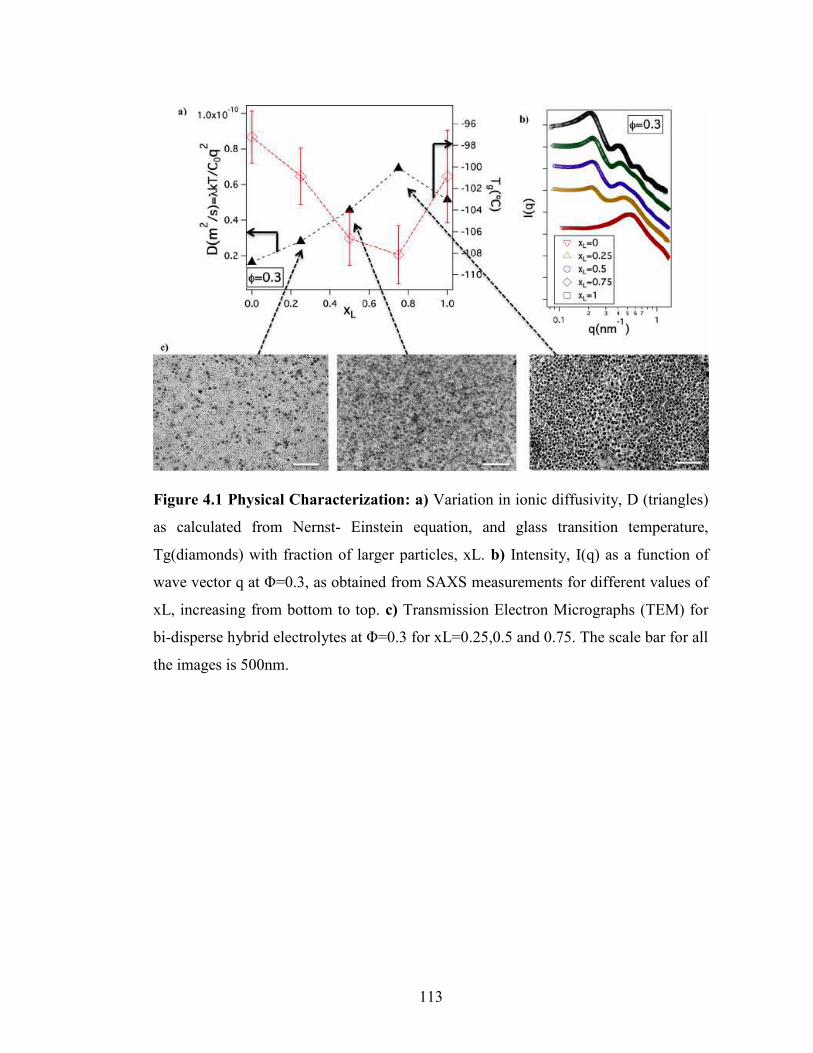
113
Figure 4.1 Physical Characterization: a) Variation in ionic diffusivity, D (triangles)
as calculated from Nernst- Einstein equation, and glass transition temperature,
Tg(diamonds) with fraction of larger particles, xL. b) Intensity, I(q) as a function of
wave vector q at Φ=0.3, as obtained from SAXS measurements for different values of
xL, increasing from bottom to top. c) Transmission Electron Micrographs (TEM) for
bi-disperse hybrid electrolytes at Φ=0.3 for xL=0.25,0.5 and 0.75. The scale bar for all
the images is 500nm.

114
bi-disperse blend of hairy particles may acquire higher configurational entropy even at
the same overall particle volume fraction. It has been observed previously that lithium-
ion transport in electrolytes containing PEO occur predominantly by local diffusion of
polymer chain segments and hopping of Li-ions between ether groups on PEO
chains.33,34 Figure 4.1(a) reports the diffusivity of lithium ions obtained, via the
Nernst-Einstein equation, from ionic conductivity data for a SiO2-PEGME/PC hybrid
electrolyte with ϕ=0.3. The figure shows that the diffusivity is a maximum near xL =
0.75. This higher diffusivity can be explained in terms of the lower interpenetration
and hence higher mobility of PEGME chains in the binary hairy particle mixtures; the
higher mobility of PEGME chains allows Li-ions in an electrolyte to migrate at a
faster rate, which results in an increase in ionic conductivity and higher ionic
diffusivity in the bi-disperse hybrid electrolytes. Figure 4.1(a) also reports the glass
transition temperature, Tg, for SiO2-PEGME/PC hybrid electrolytes as a function of xL.
Consistent with the explanation of the enhanced diffusivity at xL ≈ 0.75, it is seen that
Tg exhibits a minimum at xL close to where the maximum in diffusivity is observed. A
reduced Tg for the bi-disperse suspension implies an increased free volume, which is
consistent with our hypothesis that the tethered PEGME chains are less constrained in
the bi-disperse hybrid electrolytes. Supplementary Figure 4.1 presents results for
electrolytes with ϕ=0.2 and 0.4 and shows that the observation of a maximum
diffusivity at xL ≈ 0.75 and Tg minimum near this value is a generic feature of these
materials.
4.4.2 Structural Factor Analysis

115
Further insight about the structure of the SiO2-PEGME/PC electrolytes and about the
confinement of PEGME chains can be obtained by analyzing the SAXS structure
factor S(q) of the materials. Figure 4.2(a) compares the experimentally obtained S(q)
with the calculated structure factor for a binary hard sphere (HS) suspension using the
Percus-Yevick (PY) approximation.54 To account for the fact that a few PEGME chain
segments nearest the anchor points on the particles are likely to be completely
correlated with their particle substrate,42 the theoretical S(q) approximate the particle
size in terms of an effective radius, aeff,i= ai+ nm,ilmcos(θ/2), such that a certain number
of monomers, nm,i, are assumed to be part of the core. Here i=s,l for smaller particles
and larger particles respectively, ai is the original radius of the particle, lm=0.35nm
which is the monomer length for PEO, and θ= 68° which is the bond tetrahedral angle.
In analyzing the experimental data using the PY approximation, nm,i was treated as an
unknown variable and its value adjusted so that the peak positions of S(q) computed
for a binary HS suspension model coincide with those seen in the experimental S(q). It
can be observed from Figure 4.2(a) that whereas the S(q) peak amplitudes and
positions estimated from PY-HS analysis are in good agreement with the experimental
values for electrolytes with low f , the first S(q) maxima are much higher than the
predicted ones in electrolytes with high f . A higher first-peak height for S(q) implies
a stronger inter-particle correlation, which results in the hybrid particles from
enhanced interaction of tethered corona chains.55–57 Supplementary Figure 4.2 reports
the corresponding results for electrolytes with a range of particle size polydispersities,
xL=0, 0.25, 0.75 and 1. The discrepancy in the calculated and measured peak heights,
especially the first peak, is clearly greatest in systems with the largest asymmetry in

116
Figure 4.2 Structure Factor: a) Evolution of Structure factor, S(q) with the wave
vector q for different volume fractions, Φ=0.2, 0.3 and 0.4 at xL=0.5. The open
symbols are the experimentally obtained S(q) values and the dashed lines are
predictions from binary HS model for the same systems. The schematic above
illustrates the effective particle radius, which includes some fraction of monomers as
part of the core. b) Surface-to-surface distances, h11, h12 and h22 for the same
volume fractions as a function of xL. The graphics illustrates the two scenarios for
surface-surface distances which will be positive when there is no overlap and negative
when the polymer chains have significant overlap.

117
nanoparticle size. The discrepancy is thought to reflect enhanced interaction between
tethered oligomer chains in the hybrid particle electrolytes, which are not included in
the PY-HS analysis.
Additional insights about the structure of the electrolytes can be obtained from the PY-
HS predictions by resolving the structure factor into its three components- S11, S12 and
S22 where 1 and 2 denote smaller and larger particles respectively (see Supplementary
Figure 4.3). From the first peak positions of each of these components, three different
inter-particle distances can be obtained viz., dp-p,11, dp-p,12 and dp-p,22. Figure 4.2(b)
show the variation in surface-to-surface distance for ϕ=0.2,0.3 and 0.4, as a function of
fraction of larger particles xL. The surface-to-surface distance is calculated by
subtracting the effective core diameter from the inter-particle distance i.e. hij=dp-p,ij -
2aeff,ij, where i,j= 1 and 2 and i=j when analyzing the distance between the same
species. It can be observed that for certain values of f and xL, hij is negative which
implies that the corona chains overlap or inter-penetrate for those regions. It can be
seen that as f increases, as expected hij assumes higher negative values, implying
higher degree of interpenetration and thereby confinement for tethered chains at higher
volume fractions. For any core volume fraction f , it can also be observed that initial
addition of larger particles to a pure mono-disperse suspension of smaller ones, first
decreases the distance between the smaller particles after which the h11 value increases
with further addition of larger particles. For the same xL values, however, h22 is larger
for a smaller fraction of large particles and decreases with further increase in xL. This
implies that for smaller xL values, the larger particles confine the smaller particles and

118
increases the distance between themselves, and subsequent increase in xL values leads
to an increase in the average distance between smaller particles. This interpretation is
confirmed from the h12 values, which always increase with increase in xL, meaning
that the distance between a smaller and a larger particle always increases. Also, for the
pure mono-disperse suspensions of smaller and larger particles the hij values are either
negative or close to zero, which implies that the tethered corona chains inter-penetrate
much more in these suspensions, while hij values for bi-disperse suspensions are either
positive or less negative than their mono-disperse counterparts, which indicates less
interpenetration and hence reduced confinement of corona chain motions in bi-
disperse suspension. This observation is in agreement with the trends seen in the
diffusivity and Tg values, which confirms the hypothesis that in a bi-disperse
suspension the tethered PEO chains are less confined or have higher mobility which
subsequently leads to a higher ionic conductivity values for these hybrid electrolytes
as observed previously.35
4.4.3 Variation of interfacial resistance
Figure 4.3(a)-(c) report Nyquist plots obtained using electrochemical impedance
spectroscopy measurements to evaluate the impedance in bulk electrolyte and at the
electrode-electrolyte interface in symmetric Li/Li cells. The experimental plot is fitted
using the circuit model shown schematically in Figure 4.3, where Rb corresponds to
the resistance in bulk electrolyte, Rint represents interfacial resistance to ion migration
at the electrode-electrolyte interface, CPE is the constant phase element capacitance
near the electrode surface and Wd is the Warburg diffusion element.23 Figure 4.3(d)

119
Figure 4.3 Electrochemical Characterization: Impedance spectra for electrolytes
with core volume fractions a) Φ=0.2, b) 0.3, and c) 0.4 measured at different fractions
of larger particles added, xL. The black symbols are experimental data and the red
lines are fit to the equivalent circuit model as shown. d) Bulk resistance, Rb and e)
Interfacial resistance, Ri measured at different core volume fractions as a function of
xL.

120
and (e) summarize the magnitude of Rb and Rint as a function of xL at different core
volume fractions f , respectively. While Rb does not show significant variation with xL,
Rint decreases significantly and exhibits similar trends to those discussed earlier for the
ionic diffusivity and Tg. We postulate that the relative invariance in Rb occurs because
of adsorption of significant fraction of particles from the bulk electrolyte to the
electrode surface, which results in bulk resistance values similar to those of liquid
electrolytes with low nanoparticle loadings where ion transport is dominated by
diffusion of electrolyte solvent-ion associates. This would then also lead to variations
in interfacial resistance similar to trends seen in diffusivity due to the presence of
particles.
4.4.4 Surface Characterization of Li anode
In order to evaluate the hypothesis that surface adsorption of SiO2-PEGME particles is
the source of the weaker dependence of Rb and Rint on xL, we performed Scanning
Electron Microscopy (SEM) analysis of the lithium electrodes harvested from
symmetric Li/Li cells following galvanostatic cycling at a low current density of
0.03mA/cm2 for 10 cycles. Prior to SEM analysis, the electrodes were vigorously
washed with pure PC to remove any loosely bound material. Figure 4.4(a) shows a
representative SEM image of the Li metal electrode for small and higher
magnifications. It is apparent that a dense layer of bi-disperse particles of size 10nm
and 25nm are adsorbed to the surface of the electrode. The hairy particles appear to
form a continuous, protective film on the electrode surface.

121
It has been observed in a typical Lithium ion battery (LIB) that during charging or
discharging, oppositely charged ions accumulate near the surface of respective
electrodes.58–60 The electrochemical capacitance (EC) near the electrode surface can be
determined from the relaxation frequency f0 deduced from the Nyquist plot61–63 and its
relationship, 2πf0RintCd=1, to the interfacial resistance and capacitance.64 The
calculated capacitance can be written in terms of the dielectric constant at the interface
as, Cd=εε0A/l where, ε is the dielectric permittivity of the material at the interface, ε0 is
the vacuum permittivity, A is the surface area of the electrode and l is the thickness of
the capacitive layer. Figure 4.4(b) shows the variation in the electrochemical
capacitance Cd as a function of xL for f =0.3. It is apparent that hybrid electrolytes
based on bi-disperse SiO2-PEGME nanoparticles display higher interfacial capacitance
than the mono-disperse particle suspension. This observation can be explained either
in terms of an increase in the effective dielectric constant or a reduction in the SEI
layer thickness as xL increases. Based on the earlier observation that the particles form
a stable, dense film on the Li anode, we conclude that l is likely to be a fixed number
of the order of average particle diameter in the electrolytes. Inserting this value in the
above formula, allows us to estimate ε and, from it, an apparent Debye screening
length ( l =eeoRT2F2C0
), which is also shown as a function of xL in Fig. 4.4b. Here F is
Faraday’s constant and C0 is the molar concentration of salt in the electrolyte. For a
pure PC electrolyte containing 1M salt, λ ≈ 0.26nm, which is comparable to the
highest values obtained in Fig. 4b, but somewhat larger than the values estimated for
the electrolytes with xL= 0 or xL = 1, which is consistent with expectations for the

122
Figure 4.4 Surface Characterization: a) Scanning Electron Micrographs (SEM) for
lithium electrode surface after the symmetric cell was cycled for 10 cycles at
0.03mA/cm2 with the bi-disperse hybrid electrolyte. The schematic illustrates the
electrode surface as observed in SEM, where the particles form protective layer on the
electrode surface. b) Electrical double layer, λ(triangles) and electrochemical
capacitance per unit area, Cd(squares) for ϕ=0.3 as a function of xL.

123
factor of 5 to 10 difference in the reported dielectric constants for PEG and PC36,65–68.
One explanation of the high Cd and l values apparent at intermediate xL is that they
reflect greater access of PC to the SEI, which would increase ε. It is important to note
however, that even the largest l values are more than an order of magnitude lower
than l, meaning that the electric field gradients in the SEI layer formed by a hairy
particle coating of Li are substantially smaller than in a pure electrolyte, which would
lower both the diffusive and electro-convective flux of anions to the Li metal surface.
The Li+ transference number (tLi+) was determined by the Bruce-Scrosati method69,70
(see Supplementary Information) which was found to be approximately 0.32 for this
electrolyte, in agreement with previously reported transference numbers for PEG
based electrolytes.34 The presence of particles in the SEI therefore does not influence
the lithium ion transference number, which is consistent with expectations based on
the theoretical predictions of Jacob71, where it was found that the transference number
has a strong dependence of the ratio of pore size to double layer thickness.
4.4.5 Enhanced electrochemical stability of nanocomposites
If the Li metal in a LMB is unprotected, the electrolyte continuously reacts with the
anode to form insulating products, which increase the interfacial resistance of the
battery with time. The interface stability in symmetric cells containing SiO2-
PEGME/PC hybrid electrolyte with f =0.3 and xL =0.5 were evaluated using
impedance measurements as a function of time for a period of 2 months. It can be seen
from Figure 4.5(a) that the time-resolved impedance plots overlay well onto each
other, indicating that the particle-rich SEI layer imparts long-term enhanced chemical

124
stability to Li-metal/electrolyte interface. This enhanced stability is consistent with the
existence of a passivating particle film on the Li anode as deduced from the earlier
SEM experiments. Figure 4.5(b) reports results from linear-sweep voltammetry and
electrochemical floating-point measurements on lithium cells containing the hybrid
electrolytes. The linear sweep voltagram reveals that at higher particle volume
fractions (e.g. f =0.3 and f =0.4) and for xL =0.5 the hybrid electrolytes are stable up
to 6.5V vs. Li/Li+. In contrast, electrolytes containing lower fractions f =0.2 of
particles (inset of Figure 4.5(b)) become unstable at around 4V. The initial peak at
0.2V in all the measurements is the cathodic peak associated with the Li/Li+
reaction.7,12 Its presence for all of the materials studied means that this process is not
compromised in the hybrid electrolytes. Similar trends were also observed in the
floating-point tests in Figure 4.5(c), where hybrid electrolytes containing higher
nanoparticle volume fractions are seen to manifest negligible leakage currents even
after exposure to voltages as high as 7.5V for 5 hours. In contrast, the particle-free PC
electrolyte or a blend of un-tethered PEG in PC already exhibits high leakage currents
at 5V. Together, these results clearly show that SiO2-PEGME/PC hybrid electrolytes
with high SiO2 are exceptionally stable, in agreement with previous reports.72
4.4.6 Analyzing galvanostatic performance
As a final assessment of the ability of a nanoparticle-rich SEI to stabilize Li metal
anodes against reaction with liquid electrolytes, we analyzed the columbic efficiency
obtained in galvanostatic measurements employing Li/stainless steel electrodes. In
these experiments, a fixed amount of Li+ ions is stripped from lithium metal and

125
Figure 5 Electrochemical Stability: a) Initial impedance spectra (open symbols) for
a symmetric cell with hybrid particle electrolyte at Φ=0.3 and xL =0.5 compared with
the spectra at t=1440 hours (closed symbols). b) Variation in faradic current density, J
as a function of voltage as measured from Linear sweep voltammetry measurements
for xL =0.5 compared for Φ=0.3 (red line) and Φ=0.4 (black line). Inset shows the
measurements for neat PC (red line) and Φ=0.2 (black line). c) Leak current measured
as a function of time for different steps of voltage as measured in a floating-point test.
Profiles for symmetric cell with hybrid electrolyte at Φ=0.3 (black solid line) and
Φ=0.4 (black dashed line) are compare against neat electrolytes with PC (blue line)
and with PEG and PC (red line) blended in the same ratio as that for hybrid particle
electrolyte with Φ=0.3.

126
deposited to the stainless-steel substrate and plated back in successive runs. By
measuring the capacity ratio for the strip and plate segments of the cycle, the columbic
efficiency (CE) of the cell can be quantified. It has been reported that PC-based
electrolytes spontaneously form an insulating and unstable SEI layer on Li, yielding a
low CE of ~70%.73 It has also been shown that the CE for PC can be improved by
employing VC and LiNO3 as electrolyte additives.6,7 To study the effect of particles on
CE of Li metal electrodes, we utilized a PC-based electrolyte reinforced with 1%
LiNO3 and 2% VC as a control. It can be seen from Figure 4.6(a) that although both
the control and hybrid PC electrolytes exhibit high CE, the control electrolyte is
unable to maintain the improvements beyond ~25 cycles, implying that the VC and
LiNO3 are consumed. In contrast, the SiO2-PEGME/PC hybrid electrolyte displays
high CE for at least 80 cycles. In the control experiment, despite use of additives, the
PC electrolyte decomposes over cycles due to its low stability window and uneven
electrodeposition which exposes higher effective surface area of the electrode for the
electrolyte to react, thus the additive fails to maintain high columbic efficiency over
~25 cycles. On the other hand, as previously inferred from electrochemical stability
tests and electron microscopy, the SiO2-PEGDME form a protective monolayer on the
electrode surface that prevents constant exposure of liquid electrolyte with lithium
surface and breakdown of the additive rich SEI. This synergistic effect of the additives
and SiO2-PEGDME helps in maintaining high columbic efficiency large number of
cycles compared to the control without particles. Figure 4.6(b) shows the room-
temperature performance of the binary hybrid nanocomposite electrolytes in a
Li/LiFePO4 half-cell in which a SiO2-PEGME/PC hybrid with f = 0.3 and xL =0.5 is

127
Figure 6 Galvanostatic performance: a) Comparison of columbic efficiency as a
function of cycle number for neat PC electrolyte and hybrid particle electrolyte with
Φ=0.3 and xL =0.5 for Li|electrolyte|Stainless Steel configuration. Measurements
were performed at a current density of 0.25mA/cm2. b) Charge-discharge profiles for
Li/LFP half-cell containing hybrid particle electrolyte with Φ=0.3 and xL =0.5 at a
fixed rate of C/3 in the initial, 10th and 50th cycle.

128
employed. The figure reports the voltage profiles (voltage versus capacity) for the 1st,
10th and 50th cycles of charge and discharge. The low efficiency in the first cycle is
associated with irreversible reactions that help in forming a stable passivation layer on
the Li anode. The results in Figure 4.6(b) shows that even after 50 cycles the cells
maintain a high discharge capacity of ~130mAh/gm at C/3 rate.
4.5 Conclusion
In conclusion, we have studied hybrid electrolytes created by blending a low-volatility
carbonate (PC) with a bi-disperse mixture of SiO2-PEGDME nanoparticles. We show
that hybrid electrolytes based on bi-disperse hairy nanoparticles can be designed to
provide multiple attractive features, including exceptional high voltage stability (>
7V) over extended times; protection of a Li metal anode that allows stable-long term
cycling of the anode at high columbic efficiency; and low bulk and interfacial
resistance at room temperature that enables stable cycling of Li/LiFePO4 half cells at a
C/3 rate.
The origin of the enhanced ion mobility in bi-disperse hybrid electrolytes is shown by
means of DSC measurements, to be the reduction in Tg of the tethered PEG chains and
more fundamentally from SAXS analysis, to arise from an increase in mobility of
tethered PEGME chains due to lower levels of chain interpenetration caused by
differences in curvature of the larger and smaller particles in the bi-disperse
electrolytes. By means of interfacial impedance measurements, it was further shown
that the interfacial mobility of hybrid electrolytes at a Li metal electrode is a much

129
stronger function of polydispersity than the bulk resistance. We hypothesize that this
difference arises from the spontaneous adsorption of particles to the high energy Li
metal electrode to form a dense protective film. Post-mortem analysis of the Li
electrode surface following galvanostatic cycling shows that a dense particle-rich film
accumulates at the Li metal surface, which increases the interfacial capacitance and
appears to be very effective in limiting access of liquid electrolyte to the Li metal
surface without compromising interfacial transport of Li-ions. In contrast to control,
particle-free electrolytes, hybrid electrolytes based on bi-disperse hairy nanoparticles
are shown to enable Li/stainless steel cells with high columbic efficiency for at least
80 cycles and Li/LiFePO4 cells with high discharge capacity in extended cycling at
room-temperature.

130
REFERENCES
(1) Qian, J.; Henderson, W. a; Xu, W.; Bhattacharya, P.; Engelhard, M.; Borodin,
O.; Zhang, J.-G. High Rate and Stable Cycling of Lithium Metal Anode. Nat.
Commun. 2015, 6, 6362.
(2) Xu, W.; Wang, J.; Ding, F.; Chen, X.; Nasybulin, E.; Zhang, Y.; Zhang, J.-G.
Lithium Metal Anodes for Rechargeable Batteries. Energy Environ. Sci. 2014,
7, 513.
(3) Tu, Z.; Nath, P.; Lu, Y.; Tikekar, M. D.; Archer, L. A. Nanostructured
Electrolytes for Stable Lithium Electrodeposition in Secondary Batteries. Acc.
Chem. Res. 2015, acs.accounts.5b00427.
(4) Zheng, G.; Lee, S. W.; Liang, Z.; Lee, H.-W.; Yan, K.; Yao, H.; Wang, H.; Li,
W.; Chu, S.; Cui, Y. Interconnected Hollow Carbon Nanospheres for Stable
Lithium Metal Anodes. Nat. Nanotechnol. 2014, 9, 618–623.
(5) Aurbach, D.; Zinigrad, E.; Cohen, Y.; Teller, H. A Short Review of Failure
Mechanisms of Lithium Metal and Lithiated Graphite Anodes in Liquid
Electrolyte Solutions. Solid State Ionics 2002, 148, 405–416.
(6) Guo, J.; Wen, Z.; Wu, M.; Jin, J.; Liu, Y. Vinylene carbonate–LiNO3: A
Hybrid Additive in Carbonic Ester Electrolytes for SEI Modification on Li
Metal Anode. Electrochem. commun. 2015, 51, 59–63.

131
(7) Choudhury, S.; Mangal, R.; Agrawal, A.; Archer, L. A. A Highly Reversible
Room-Temperature Lithium Metal Battery Based on Crosslinked Hairy
Nanoparticles. Nat. Commun. 2015, 1–9.
(8) Chen, L.; Wang, K.; Xie, X.; Xie, J. Effect of Vinylene Carbonate (VC) as
Electrolyte Additive on Electrochemical Performance of Si Film Anode for
Lithium Ion Batteries. J. Power Sources 2007, 174, 538–543.
(9) Xu, K.; Zhang, S.; Jow, T. R. LiBOB as Additive in LiPF[sub 6]-Based Lithium
Ion Electrolytes. Electrochem. Solid-State Lett. 2005, 8, A365.
(10) Li, W.; Yao, H.; Yan, K.; Zheng, G.; Liang, Z.; Chiang, Y.-M.; Cui, Y. The
Synergetic Effect of Lithium Polysulfide and Lithium Nitrate to Prevent
Lithium Dendrite Growth. Nat. Commun. 2015, 6, 7436.
(11) Choudhury, S.; Archer, L. A. Lithium Fluoride Additives for Stable Cycling of
Lithium Batteries at High Current Densities. Adv. Electron. Mater. 2015, 1–6.
(12) Lu, Y.; Tu, Z.; Archer, L. A. Stable Lithium Electrodeposition in Liquid and
Nanoporous Solid Electrolytes. Nat. Mater. 2014, 13, 961–969.
(13) Pires, J.; Timperman, L.; Castets, A.; Santos-pena, J.; Dumont, E.; Levasseur,
S.; Dedryvere, R.; Tessier, C.; Anouti, M. Role of Propane Sultone as Additive
to Improve the Performance of Lithium-Rich Cathode Material at High
Potential. RSC Adv. 2015.

132
(14) Li, B.; Xu, M.; Li, T.; Li, W.; Hu, S. Prop-1-Ene-1,3-Sultone as SEI Formation
Additive in Propylene Carbonate-Based Electrolyte for Lithium Ion Batteries.
Electrochem. commun. 2012, 17, 92–95.
(15) Etacheri, V.; Haik, O.; Goffer, Y.; Roberts, G. A.; Stefan, I. C.; Fasching, R.;
Aurbach, D. Effect of Fluoroethylene Carbonate (FEC) on the Performance and
Surface Chemistry of Si-Nanowire Li-Ion Battery Anodes. Langmuir 2012, 28,
965–976.
(16) Miao, R.; Yang, J.; Feng, X.; Jia, H.; Wang, J.; Nuli, Y. Novel Dual-Salts
Electrolyte Solution for Dendrite-Free Lithium-Metal Based Rechargeable
Batteries with High Cycle Reversibility. J. Power Sources 2014, 271, 291–297.
(17) Luo, W.; Zhou, L.; Fu, K.; Yang, Z.; Wan, J.; Manno, M.; Yao, Y.; Zhu, H.;
Yang, B.; Hu, L. A Thermally Conductive Separator for Stable Li Metal
Anodes. Nano Lett. 2015, 150810091733009.
(18) Liang, Z.; Zheng, G.; Liu, C.; Liu, N.; Li, W.; Yan, K.; Yao, H.; Hsu, P.-C.;
Chu, S.; Cui, Y. Polymer Nanofiber-Guided Uniform Lithium Deposition for
Battery Electrodes. Nano Lett. 2015, 150330172314009.
(19) Lu, Y.; Tikekar, M.; Mohanty, R.; Hendrickson, K.; Ma, L.; Archer, L. A.
Stable Cycling of Lithium Metal Batteries Using High Transference Number
Electrolytes. Adv. Energy Mater. 2015, 5, n/a – n/a.

133
(20) Schaefer, J. L.; Yanga, D. A.; Archer, L. A. High Lithium Transference
Number Electrolytes via Creation of 3-Dimensional, Charged, Nanoporous
Networks from Dense Functionalized Nanoparticle Composites. Chem. Mater.
2013, 25, 834–839.
(21) Ozhabes, Y.; Gunceler, D.; Arias, T. A. Stability and Surface Diffusion at
Lithium-Electrolyte Interphases with Connections to Dendrite Suppression.
arXiv 2015, 1504.05799, 1–7.
(22) Khurana, R.; Schaefer, J. L.; Archer, L. A; Coates, G. W. Suppression of
Lithium Dendrite Growth Using Cross-Linked Polyethylene/poly(ethylene
Oxide) Electrolytes: A New Approach for Practical Lithium-Metal Polymer
Batteries. J. Am. Chem. Soc. 2014, 136, 7395–7402.
(23) Tu, Z.; Kambe, Y.; Lu, Y.; Archer, L. A. Nanoporous Polymer-Ceramic
Composite Electrolytes for Lithium Metal Batteries. Adv. Energy Mater. 2014,
4, n/a – n/a.
(24) Gurevitch, I.; Buonsanti, R.; Teran, a. a.; Gludovatz, B.; Ritchie, R. O.; Cabana,
J.; Balsara, N. P. Nanocomposites of Titanium Dioxide and Polystyrene-
Poly(ethylene Oxide) Block Copolymer as Solid-State Electrolytes for Lithium
Metal Batteries. J. Electrochem. Soc. 2013, 160, A1611–A1617.
134
(25) Bouchet, R.; Maria, S.; Meziane, R.; Aboulaich, A.; Lienafa, L.; Bonnet, J.;
Phan, T. N. T.; Bertin, D.; Gigmes, D.; Devaux, D.; et al. Efficient Electrolytes
for Lithium-Metal Batteries. Nat. Mater. 2013, 12, 452–457.
(26) Weston, J. E.; Steele, B. C. H. Effects of inert fillers on the mechanical and
electrochemical properties of lithium salt-poly ( ethylene oxide ) polymer
electrolytes _ i b. Solid State Ionics 1982, 7, 75–79.
(27) Croce, F.; Scrosati, B. Nanocomposite Lithium Ion Conducting Membranes.
Ann. N.Y. Acad Sci. 984 2003, 207, 194–207.
(28) Agrawal, A.; Choudhury, S.; Archer, L. A. A Highly Conductive, Non-
Flammable Polymer-Nanoparticle Hybrid Electrolyte. RSC Adv. 2015.
(29) Srivastava, S.; Schaefer, J. L.; Yang, Z.; Tu, Z.; Archer, L. A. 25Th
Anniversary Article: Polymer-Particle Composites: Phase Stability and
Applications in Electrochemical Energy Storage. Adv. Mater. 2014, 26, 201–
234.
(30) Lu, Y.; Korf, K.; Kambe, Y.; Tu, Z.; Archer, L. A. Ionic-Liquid-Nanoparticle
Hybrid Electrolytes: Applications in Lithium Metal Batteries. Angew. Chemie
2014, 126, 498–502.
(31) Lu, Y.; Das, S. K.; Moganty, S. S.; Archer, L. A. Ionic Liquid-Nanoparticle
Hybrid Electrolytes and Their Application in Secondary Lithium-Metal
Batteries. Adv. Mater. 2012, 24, 4430–4435.

135
(32) Korf, K. S.; Lu, Y.; Kambe, Y.; Archer, L. A. Piperidinium Tethered
Nanoparticle-Hybrid Electrolyte for Lithium Metal Batteries. J. Mater. Chem. A
2014, 2, 11866–11873.
(33) Nugent, J. L.; Moganty, S. S.; Archer, L. a. Nanoscale Organic Hybrid
Electrolytes. Adv. Mater. 2010, 22, 3677–3680.
(34) Schaefer, J. L.; Moganty, S. S.; Yanga, D. A.; Archer, L. A. Nanoporous
Hybrid Electrolytes. J. Mater. Chem. 2011, 21, 10094.
(35) Agrawal, A.; Choudhury, S.; Archer, L. A. A Highly Conductive, Non-
Flammable Polymer–nanoparticle Hybrid Electrolyte. RSC Adv. 2015, 5,
20800–20809.
(36) Zhang, Q.; Archer, L. A. Poly(ethylene oxide)/Silica Nanocomposites:
Structure and Rheology. Langmuir 2002, 18, 10435–10442.
(37) Moganty, S. S.; Jayaprakash, N.; Nugent, J. L.; Shen, J.; Archer, L. A. Ionic-
Liquid-Tethered Nanoparticles: Hybrid Electrolytes. Angew. Chemie 2010, 122,
9344–9347.
(38) Hussain, F. Review Article: Polymer-Matrix Nanocomposites, Processing,
Manufacturing, and Application: An Overview. J. Compos. Mater. 2006, 40,
1511–1575.

136
(39) Palmqvist, A. E. C. Synthesis of Ordered Mesoporous Materials Using
Surfactant Liquid Crystals or Micellar Solutions. Curr. Opin. Colloid Interface
Sci. 2003, 8, 145–155.
(40) Balazs, A. C.; Emrick, T.; Russell, T. P. Nanoparticle Polymer Composites :
Meet Two Small Worlds. Science (80-. ). 2013, 314, 1107–1110.
(41) Mangal, R.; Srivastava, S.; Archer, L. A. Phase Stability and Dynamics of
Entangled Polymer–nanoparticle Composites. Nat. Commun. 2015, 6, 1–9.
(42) Green, D. L.; Mewis, J.; Engineering, C.; Uni, V.; Way, E.; Charlottes, V.
Connecting the Wetting and Rheological Behaviors of Poly ( Dimethylsiloxane
) -Grafted Silica Spheres in Poly ( Dimethylsiloxane ) Melts. Langmuir 2006,
9546–9553.
(43) Srivastava, S.; Agarwal, P.; Archer, L. A. Tethered Nanoparticle-Polymer
Composites: Phase Stability and Curvature. Langmuir 2012, 28, 6276–6281.
(44) McEwan, M.; Green, D. Rheological Impacts of Particle Softness on Wetted
Polymer-Grafted Silica Nanoparticles in Polymer Melts. Soft Matter 2009, 5,
1705.
(45) Dutta, N.; Green, D. Nanoparticle Stability in Semidilute and Concentrated
Polymer Solutions. Langmuir 2008, 24, 5260–5269.

137
(46) Lindenblatt, G.; Schärtl, W.; Pakula, T.; Schmidt, M. Structure and Dynamics
of Hairy Spherical Colloids in a Matrix of Nonentangled Linear Chains.
Macromolecules 2001, 34, 1730–1736.
(47) Oh, H.; Green, P. F. Polymer Chain Dynamics and Glass Transition in
Athermal Polymer/nanoparticle Mixtures. Nat. Mater. 2009, 8, 139–143.
(48) Meng, D.; Kumar, S. K.; D. Lane, J. M.; Grest, G. S. Effective Interactions
between Grafted Nanoparticles in a Polymer Matrix. Soft Matter 2012, 8, 5002.
(49) Ohno, K.; Morinaga, T.; Takeno, S.; Tsujii, Y.; Fukuda, T. Suspensions of
Silica Particles Grafted with Concentrated Polymer Brush: Effects of Graft
Chain Length on Brush Layer Thickness and Colloidal Crystallization.
Macromolecules 2007, 40, 9143–9150.
(50) Glatter, O.; Kratky, O. Small Angle X-Ray Scattering; United Sta.; Academic
Press: New York, 1982.
(51) Zaccarelli, E.; Mayer, C.; Asteriadi, A.; Likos, C.; Sciortino, F.; Roovers, J.;
Iatrou, H.; Hadjichristidis, N.; Tartaglia, P.; Löwen, H.; et al. Tailoring the
Flow of Soft Glasses by Soft Additives. Phys. Rev. Lett. 2005, 95, 268301.
(52) Mayer, C.; Zaccarelli, E.; Stiakakis, E.; Likos, C. N.; Sciortino, F.; Munam, A;
Gauthier, M.; Hadjichristidis, N.; Iatrou, H.; Tartaglia, P.; et al. Asymmetric
Caging in Soft Colloidal Mixtures. Nat. Mater. 2008, 7, 780–784.

138
(53) Agrawal, A.; Yu, H.-Y.; Srivastava, S.; Choudhury, S.; Narayanan, S.; Archer,
L. Dynamics and Yielding of Binary Self-Suspended Nanoparticle Fluids. Soft
Matter 2015, 11, 5224–5234.
(54) Ashcroft, N. W.; Langreth, D. C. Structure of Binary Liquid Mixtures. I. Phys.
Rev. 1967, 16, 685–692.
(55) Srivastava, S.; Shin, J. H.; Archer, L. a. Structure and Rheology of
Nanoparticle–polymer Suspensions. Soft Matter 2012, 8, 4097.
(56) Yu, H.-Y.; Srivastava, S.; Archer, L. A; Koch, D. L. Structure Factor of Blends
of Solvent-Free Nanoparticle-Organic Hybrid Materials: Density-Functional
Theory and Small Angle X-Ray Scattering. Soft Matter 2014, 10, 9120–9135.
(57) Choudhury, S.; Agrawal, A.; Kim, S. A; Archer, L. A. Self-Suspended
Suspensions of Covalently Grafted Hairy Nanoparticles. Langmuir 2015, 31,
3222–3231.
(58) Qu, D.; Qu, D.; Shi, H.; Shi, H. Studies of Activated Carbons Used in Double-
Layer Capacitors. J. Power Sources 1998, 74, 99–107.
(59) Shi, H. Activated Carbons and Double Layer Capacitance. Electrochim. Acta
1996, 41, 1633–1639.
(60) Choi, N. S.; Chen, Z.; Freunberger, S. a.; Ji, X.; Sun, Y. K.; Amine, K.; Yushin,
G.; Nazar, L. F.; Cho, J.; Bruce, P. G. Challenges Facing Lithium Batteries and

139
Electrical Double-Layer Capacitors. Angew. Chemie - Int. Ed. 2012, 51, 9994–
10024.
(61) Flandrois, S.; Simon, B. Carbon Materials for Lithium-Ion Rechargeable
Batteries. Carbon N. Y. 1999, 37, 165–180.
(62) Shiraishi, S.; Kurihara, H.; Tsubota, H.; Oya, A.; Soneda, Y.; Yamada, Y.
Electric Double Layer Capacitance of Highly Porous Carbon Derived from
Lithium Metal and Polytetrafluoroethylene. Electrochem. Solid-State Lett.
2001, 4, A5–A8.
(63) Largeot, C.; Portet, C.; Chmiola, J.; Taberna, P. L.; Gogotsi, Y.; Simon, P.
Relation between the Ion Size and Pore Size for an Electric Double-Layer
Capacitor. J. Am. Chem. Soc. 2008, 130, 2730–2731.
(64) Lanfredi, S.; Rodrigues, a. C. M. Impedance Spectroscopy Study of the
Electrical Conductivity and Dielectric Constant. J. Appl. Phys. 1999, 86, 2215.
(65) Payne, R.; Theodorou, I. E. Dielectric Properties and Relaxation in Ethylene
Carbonate and Propylene Carbonate. J. Phys. Chem. 1972, 76, 2892–2900.
(66) Simeral, L.; Ameyib, R. L.; Amey, L. Dielectric Properties of Liquid Propylene
Carbonate ’". J. Phys. Chem. 1970, 74, 1968–1971.
(67) Sengwa, R. J.; Kaur, K.; Chaudhary, R. Dielectric Properties of Low Molecular
Weight Poly ( Ethylene Glycol ) S. Polym Int. 2000, 608, 599–608.

140
(68) Schneider, U.; Lunkenheimer, P.; Brand, R.; Loidl, A. Broadband Dielectric
Spectroscopy on Glass-Forming Propylene Carbonate. Phys. Rev. E. Stat. Phys.
Plasmas. Fluids. Relat. Interdiscip. Topics 1999, 59, 6924–6936.
(69) Bruce, P. Conductivity and Transference Number Measurements on Polymer
Electrolytes. Solid State Ionics 1988, 28-30, 918–922.
(70) Appetecchi, G. B. A New Class of Advanced Polymer Electrolytes and Their
Relevance in Plastic-Like, Rechargeable Lithium Batteries. J. Electrochem.
Soc. 1996, 143, 6.
(71) Jorne, J. Transference Number Approaching Unity in Nanocomposite
Electrolytes. Nano Lett. 2006, 6, 2973–2976.
(72) Capuano, F.; Croce, F.; Scrosati, B. Composite Polymer Electrolytes. J.
Electrochem. Soc. 2003, 203, 197–203.
(73) Ding, F.; Xu, W.; Graff, G. L.; Zhang, J.; Sushko, M. L.; Chen, X.; Shao, Y.;
Engelhard, M. H.; Nie, Z.; Xiao, J.; et al. Dendrite-Free Lithium Deposition via
Self-Healing Electrostatic Shield Mechanism. J. Am. Chem. Soc. 2013, 135,
4450–4456.
(74) Jonscher, A. K. The “Universal” Dielectric Response. Nature 1977, 267, 673–
679.

141
APPENDIX
Supplementary Information for Chapter 4
Supplementary Figure 4.1 Variation of glass transition temperature (open symbols)
and diffusivity (close symbols) as a function of fraction of larger particles xL, for core
volume fraction a) ϕ=0.2 and b) ϕ=0.4. The dashed lines are guide to eye.

142
Supplementary Figure 4.2 Evolution of structure factor S(q) as a function of the
wave vector q at volume fractions Φ=0.2, 0.3 and 0.4 for a) xL=0, b) xL=0.25, c)
xL=0.75, and d) xL=1. The open symbols are experimental values and the dashed
lines are fit to experimental S(q) using binary Hard Sphere model.

143
Supplementary Figure 4.3 Variation in three components of structure factor viz.,
S11, S12, and S22 as estimated from Binary Hard Sphere model predictions. Here, 1
and 2 indicate smaller and larger particles respectively. The structure factors are
shown for xL=0.5 for different volume fraction a) Φ=0.2, b) Φ=0.3, and c) Φ=0.4.

144
Supplementary Figure 4.4 Electrical double layer (square symbols) and
electrochemical capacitance (triangle symbols) for different values of xL at a) Φ=0.2
and b) Φ=0.4

145
Supplementary Figure 4.5 a) Electrochemical impedance measurements for a
symmetric lithium cell before polarization (open symbols) and after steady state is
reached (closed symbols). R0 and Rss were determined by fitting these impedances to
the circuit model mentioned in the main text. b) Current decay for the cell undergoing
polarization at 20mV potential. I0 and ISS were used in the calculations as observed in
the plot.

146
CHAPTER 5
A HIGHLY REVERSIBLE ROOM TEMPERATURE LITHIUM METAL
BATTERY BASED ON CROSS-LINKED HAIRY NANOPARTICLES

147
5.1 Abstract
Rough electrodeposition, uncontrolled parasitic side-reactions with electrolytes, and
dendrite induced short-circuits have hindered development of advanced energy storage
technologies based on metallic Li, Na and Al electrodes. Solid polymer electrolytes
and nanoparticle-polymer composites have shown promise as candidates to suppress
Li dendrite growth, but the challenge of simultaneously maintaining high mechanical
strength and high ionic conductivity at room temperature has so far been unmet in
these materials. Here, we report a facile and scalable method of fabricating tough,
freestanding membranes that combine the best attributes of solid polymers,
nanocomposites, and gel-polymer electrolytes. Hairy nanoparticles are employed as
multifunctional nodes for polymer cross-linking, which produces mechanically robust
membranes that are exceptionally effective in inhibiting dendrite growth in a lithium
metal battery. The membranes are also reported to enable stable cycling of Lithium
batteries paired with conventional intercalating cathodes. Our findings appear to
provide an important step towards room temperature dendrite-free batteries.
5.2 Introduction
The search for portable, high capacity and safe electrical energy storage technologies
remains one of the paramount motivators for materials research. High voltage
cathodes, high energy anodes, and highly conductive, but stable electrolytes for
lithium-ion batteries (LIBs) have received a lop-sided share of the attention by
researchers because of their multiple attractive features, including high energy density,
light weight, high operating voltage and minimal memory effects1–3. Secondary

148
lithium metal batteries (LMBs), wherein metallic lithium serves as the anode, are an
attractive alternative to LIBs, but are known to have a serious problem associated with
dendrite-induced short circuits4. During repeated cycles of charge and discharge, the
uneven deposition of Li-ion on this metal lead to the formation of ramified structures,
which grow unstably, puncture the separator, and ultimately causes cell failure by
short circuiting the anode and cathode. Over the years, a growing number of studies
have explored electrolyte and separator platforms to suppress the dendrite growth in
an effort to enable LMBs5,6. Recent efforts have focused on stabilizing the surface of
the Li anode using electrolyte additives7–9, hybrid ionic liquid nanostructures10,11, or
by using a high modulus separator12–14, which can also provide a means of applying
compression forces to stabilize the anode during deposition. Infusion of a nanoporous
ceramic or polymer membrane separator with a liquid electrolyte that can facilitate Li
ions transfer, without compromising the mechanical properties of the nanoporous
membrane, provides a more straightforward route towards mechanically strong, room-
temperature electrolytes/separators that prevent dendrite growth15,16.
Solid or gel-polymer electrolyte have been researched extensively for their ability to
enable batteries in various form factors that are leakage free, flexible, yet safer12–14,17–
21. However, these gel electrolyte systems have consistently underperformed in terms
of the ionic conductivity requirements for room-temperature operation of advanced
batteries22. In a block copolymer solid electrolyte system, the ratio of the hard non-
conducting phase to the soft conducting phase determines the mechanical strength of
the system. It has been shown for instance that in poly(styrene)-poly(ethylene oxide)

149
(PS-PEO) electrolytes, a PS/PEO molar ratio of around unity provides a good balance
between mechanical strength and ionic conductivity23. However, the abundance of the
non-conducting, reinforcing PS phase still results in low bulk conductivity relative to
liquid electrolytes, necessitating elevated temperature battery operation, which is a
limitation for many consumer-based applications. Nanocomposite electrolytes
comprised of liquid or polymeric electrolytes reinforced with nanoparticle fillers can
achieve higher modulus at lower reinforcing material content, which potentially offers
multiple straightforward paths towards electrolytes with high modulus and acceptable
room-temperature ionic conductivity24–28. Uniform dispersion of the fillers in the
polymer host is understood to be a prerequisite to prevent particle agglomeration and
local inhomogeneity in the electrolyte medium. Unfortunately, strong attractive Van
der Waals and depletion forces on the particles result in particle aggregation and phase
separation29,30. Several recent studies have shown that various physical and chemical
modifications of nanoparticle-polymer interactions can lead to dramatic improvements
in phase stability and electrolyte properties of such systems29,31–34.
A strategy towards a hybrid electrolyte platform, which can provide high ionic
conductivity and attractive mechanical properties, is designing a cross-linked polymer
web in which hairy nanoparticles serve as cross-linkers. A perhaps obvious benefit of
this design is that chemistry introduced on the surface of the precursor particles can be
presented in the pores of the cross-linked material to selectively pass Li ions while
hindering the unstable dendrite growth. Here, we report the first realization of this
concept and show that an electrolyte with the proposed design combining the

150
advantages of a nanocomposite and solid polymer electrolyte. In the systems reported
herein, a hydrophobic polymer provides a porous conductive pathway for Li ions
while a short hydrophilic oligomer tethered to the nanoparticle surface constrain the
network providing structure and mechanical strength. The nanoparticle-induced cross-
linking of the polymer prevents particle aggregation, which is known to compromise
flexibility and elasticity of nanocomposites.
5.3 Methods
5.3.1 Materials
Ludox SM30 colloidal silica (d = 10±2 nm), poly(propylene glycol)-toluene-2,4-
diisocyante, propylene carbonate, Bis(trifluoromethane) sulfonamide lithium salt,
ethylene carbonate/ diethylene carbonate (1v:1v) with lithium hexafluorophosphate
were all purchased from Sigma Aldrich. Hydoxy terminated poly (ethylene oxide)-
silane was obtained from Gelest. All the chemicals were used as received in
appropriate conditions.
5.3.2 Nanoparticle-Polymer Crosslink Synthesis and Composite Electrolyte
Preparation
Crosslinked-Nanoparticle-Polymer-Composites (CNPC) were synthesized using a
two-step process. In the first step, colloidal silica was grafted with hydroxy-
poly(ethylene oxide)-silane [500Da] in water by the reaction of silanol groups of the
PEO chain and OH- groups on the silica particle. A predetermined amount of the

151
Ludox SM30 and a large excess of the hydroxy-PEO-Silane was first heated at 80OC
for a period of two days, before centrifuging the thus obtained mixture in a
chloroform-hexane mixed solvent five times at a speed of 8500rpm for 10 minutes in
order to remove all unlinked PEO from the hairy nanoparticles. The recovered OH-
PEO-SiO2 hairy particle suspension was rigorously dried and saved for the next
reaction step. In the second step, poly(propylene glycol)-toluene-2,4-diisocyante and
the OH-PEO-SiO2 nanoparticles were combined in a 4:1 ratio by weight and dissolved
anhydrous chloroform using a vortex mixer. The obtained solution was casted onto a
rectangular Teflon mould of desired size. The mixture was allowed to crosslink
overnight under ambient conditions to produce CNPC films/membranes of desired
thicknesses. The resultant membranes were characterized using TGA, DSC and FTIR.
In order to use the synthesized CNPC membranes as battery electrolytes, they were
soaked for a period of two days in conventional liquid electrolytes in an Argon-filled
Glove Box.
5.3.3 TEM and Small Angle X-ray Scattering
The nanoscale structure of the as prepared CNPC membranes was characterized using
a FEI T12 Spirit TEM. For these measurements, a thin layer of the precursor material
was casted onto the TEM grid, allowing it to crosslink on the grid. Before TEM
imaging, coated grids were dried overnight using the same procedure used to prepare
the freestanding CNPC membranes. Small Angle X-ray Scattering (SAXS)
measurements were performed at the Cornell High Energy Synchotron Source

152
(CHESS) on a strip of the CNPC film using a point collimated X-ray source at room
temperature.
5.3.4 Mechanical Properties
Mechanical properties of CNPC membranes and CNPC electrolytes were analyzed
using dynamic mechanical analysis (DMA Q800) at room temperature. A fixed strain
of 0.1% was applied on the strip over a range of frequency of 1Hz to 100Hz, in order
to obtain the storage modulus of the samples. A similar experiment was done on the
Silica-PPO suspension using an Anton Paar MCR501 shear Rheometer in order to
characterize the effect of cross-linking on mechanical properties of the materials.
5.3.5 Electrochemical Characterization
The ionic conductivity of CNPC electrolytes was measured as a function of
temperature using a Novocontrol N40 Broadband Dielectric instrument. The d.c.
conductivity was obtained from the plateau, high frequency region of the a.c.
conductivity versus frequency data. Impedance Spectroscopy measurements were
performed using a Solatron frequency analyzer. A two-electrode, symmetric Li|Li cell
in which the CNPC electrolyte was sandwiched between lithium foils was studied in a
frequency range from 10-3Hz to 107Hz. Linear sweep and cyclic voltammetry were
performed at a sweep rate of 1mV/s between -0.2V to 6.5V using Li/CNPC
electrolyte/Stainless Steel cells to quantify the voltage stability window of the
electrolytes.

153
5.3.6 Cell Lifetime and Failure Studies
Symmetric 2032 type Li|Li coin cells containing either liquid of CNPC electrolytes
were prepared inside an Argon-filled Glove Box. To facilitate comparisons, all cells
used in this component of the study also included a standard Celgard separator, with a
diameter of 6.4 mm. The cells were evaluated using both galvanostatic (strip-plate)
cycling and in step current (polarization) modes over a range of current density using a
Neware CT-3008 battery tester. In the ‘strip-plate’ experiments, the cells were charged
and discharged at a predetermined current density for a period of three hours each.
Failure was deduced either from a sudden drop of the resultant voltage waveform or
when the waveform exhibited new harmonics and displayed irregular time
dependence. In the polarization experiments, the symmetric cells were constantly
charged at a particular current density until the cell failed. In this case failure was
determined either by a sudden drop in the resultant voltage profile or by the
appearance of irregular transients in the voltage profile. Postmortem characterization
of the lithium surface after cycling was used to corroborate our conclusions about
failure from the electrical response of the cells and for assessing the surface structure
of Li in cells that showed no electrical signatures of failure. For this purpose, cells
were dissembled in the glove box and the Li foil removed and was washed repeatedly
in pure PC to remove the electrolyte, before performing SEM (LEO155FESEM)
analysis.
5.3.7 Measuring the Coulombic Efficiency
154
Li| electrolyte |Stainless steel 2032 type coin cells were assembled in an Argon-filled
Glove Box. Control experiments using liquid electrolytes comprised of 1M LiTFSI-
PC with 1%(w.t.) LiNO3 and 2%(vol.) vinylene carbonate additives and a standard
Celgard separator were compared to measurements using CNPC electrolytes created
by soaking CNPC membranes in these same liquid electrolytes. In both cases, prior to
the measurements, cells were conditioned by cycling them between 0 to 0.5V for 10
cycles, following a procedure reported in literature44 thought to enable formation of a
stable SEI layer on the electrodes. To characterize the columbic efficiency, the
conditioned cells were first discharged at a constant current density of 0.25mA/cm2 for
2 hours to transfer an amount of lithium corresponding to 0.50mAh/cm2 of charge
from the Li electrode to the stainless steel electrode. The amount of charge recovered
in the reverse cycle when the cell is charged back to 0.5V at the same current density
was recorded, and the fractional recovery used to determine the Columbic efficiency.
5.3.8 Half-cell testing
Both LTO and LFP cathodes were prepared by mixing the active materials with Super
P carbon and PVDF binder in the ratio of 8:1:1, by weight, in the presence of NMP,
and casting a layer of the resultant slurry onto aluminum foil. Next, the cathode was
dried first at room temperature and then at 70OC overnight under vacuum. The surface
capacity of both the films was maintained constant as 0.5mAh/cm2. Li|CNPC
electrolyte|LTO and Li|CNPC electrolyte|LFP 2032 type coin cells were assembled
under argon environment in a glove box.

155
5.4 Results
5.4.1 Synthesis and Physical characterization of crosslinked membrane
Figure 5.1(a) is a schematic of the reaction steps involved in the synthesis of our
cross-linked hybrid electrolyte material. First, short-chained oligomers, poly(ethylene
oxide)-500Da, are grafted onto silica particles to form nanoparticle organic hybrids
with reactive end groups. The PEO-tethered silica particles are next linked with
difunctional poly(propylene oxide)-2000Da (PPO) to form the cross-linked
nanoparticle-polymer composite (CNPC) in a desired macroscopic shape. The
materials used in the present study achieve high levels of cross-linking by two-
reaction mechanisms: dimerization between isocyanate end groups in PPO and
reaction between isocyanate group in PPO and end-functional hydroxyl groups on the
hairy nanoparticles to form stable urethane linkages. The CNPC membrane (Figure
5.1(c)) is mechanically tough and has a ‘rubbery’ texture. In order to use it as a
composite electrolyte, the membrane was soaked in a liquid electrolyte comprised of
propylene carbonate (PC) containing 1M lithium bis(trifluoromethanesulfonyl)imide
(LiTFSI) salt for a period of two days. This step yields a material with a swollen, gel-
like appearance (shown in Figure 5.1(d)), but with little loss of the solid
nanocomposite material’s mechanical strength. In contrast, it is seen that on soaking
with electrolyte the un-crosslinked components separate out in the liquid, leaving
behind a transparent film with no observable particle aggregates. For brevity, the
CNPC membranes infiltrated with liquid electrolytes are hereafter referred to as CNPC
electrolytes.

156
The reaction progress can be facilely mapped using Fourier transform infrared
spectroscopy (FTIR) as illustrated in Supplementary Figure 5.2. It is evident that the -
NCO bond at (2270cm-1) present in the neat PPO-diisocyanate polymer is consumed
in the reaction and at same time generates a urethane linkage, evident by the -NH
vibration (3288cm-1) and -C=O bond peak (1680cm-1). TGA analysis of these
materials (Supplementary Figure 5.2) shows that the freestanding crosslinked film
contains 6% silica by weight and in the final CNPC electrolyte material the silica
content is 2% (Supplementary Table 5.2), thus there is a preponderance of ion-
conducting entity in the material. Significantly, because the silica particles are nano
sized (~10nm) and have multiple chains attached to their surface (~55 chains/particle),
each particle provides a large number of node points for cross-linking the PPO
polymer. Thus, even a low particle content in the precursor material is expected to
enable extensive cross-linking via particle nodes, which should lead to dramatic
improvements in mechanical properties without compromising room temperature ionic
conductivity of the liquid electrolyte hosted by a CNPC membrane.
The synthesized CNPC membranes were characterized using differential scanning
calorimetry (DSC) measurements (Supplementary Figure 5.3), which reveal a low
glass transition temperature (Tg) of -630C for neat PPO polymer, after crosslinking, Tg
increases to -420C. The dispersion and arrangement of nanoparticles in the cross-
linked polymer matrix is important for the targeted application as nanostructured
electrolytes. Figure 5.1(b) shows a 2D image of a thin layer of the material obtained
from Transmission Electron Microscopy (TEM). The image shows that the particles

157
organize in disordered inter-connected, string-like phases to produce tortuous pores
with an average diameter of 24 ± 2 nm estimated from the TEM micrograph (see
Supplementary Figure 5.4). Small Angle X-ray Scattering (SAXS) has been used
previously to study particle packing and polymer-nanoparticle interactions in bulk
nanocomposite based electrolyte materials35–37. Figure 5.1(e) shows the experimental
Intensity I(q) as a function of wave number (q) obtained from SAXS measurements on
CNPCs. The solid line through the experimental I(q) data was obtained using the
Beaucage Unified model (see Supporting Information). The power-law scattering
regime I(q) ∼ q- a , with exponent a » 2observed at low q indicates that the particles
in the materials are organized in the form of mass fractals with sizes in the range 50
nm to 70 nm. The shoulder at q = qs » 0.6nm-1 implies that the scattering originates
from particles with average diameter d = 2p / qs » 10.5nm, which is close to the
average diameter of the SiO2 nanocores used for synthesizing the materials. Finally,
the absence of any additional structure contribution (maxima) in I(q) in the
intermediate and high q regime means that the primary particles are reasonably far
apart. The interparticle distance can be theoretically calculated assuming random
packing of hard spheres in suspension, dp-p= d(0.63/ϕ)1/3, where d is the nanoparticle
diameter and ϕ is the volume fraction of particles in the polymer network. This
analysis yields an interparticle spacing of approximately 27nm, which is comparable
to the particle separation of 24 ± 2 nm deduced from analysis of the TEM image in
Figure 5.1(b) (see Supplementary Figure 5.4). Thus, the TEM and SAXS results imply
that in a freestanding CNPC membrane, randomly distributed particles organize in
string-like phases to form tortuous path for ion and mass transport through the

158
Figure 5.1: From hybrid nanostructure to macroscale membrane: Clockwise. a,
The first row shows the scheme of reaction involved in the synthesis of the free-
standing Crosslinked Nanoparticle Polymer Composite. Silica tethered with Hydroxy-
terminated Polyethylene Oxide is reacted with Polypropylene Oxide-Diisocyanate
with a weight ratio of 1:4 at room temperature in a Teflon mould of appropriate shape.
b, TEM image of the Crosslinked membrane. The black circles are silica particle
dispersed in the polymer matrix. c, The photograph of a free-standing membrane is
shown. Physically it has a rubbery texture and is transperent. d, Image of the wet
polymer gel is shown which is obtained by long time soaking of the prepared
membrane in unimolar electrolyte liquid. e, Scattered intensity I(q) vs wave vector q
profile obtained from SAXS measurements. Solid line represents the fit for Beaucage
Unified model to the data. The fit in the low q regime shows a power law scattering
( ( ) ~I q q D� ) with an exponent (D) of around 2, indicating the presence of mass
fractals

159
materials. Such nanostructured materials have been hypothesized, largely without
proof, to be excellent candidates to hinder dendrite-induced short circuit in Lithium
batteries13,14,20.
5.4.2 Mechanical and Electrochemical properties of crosslinked membrane
Figure 5.2(a) reports the storage modulus as a function of frequency for a freestanding
CNPC film before and after soaking in liquid electrolyte. The storage modulus of a
suspension of PPO in silica is also shown in the figure. Clearly, cross-linking
increments the modulus by several orders of magnitude. The mechanical strength of
the material is about five orders of magnitude higher than a neat PEO based
electrolyte, and is comparable to the elastic shear modulus reported for dry PS-PEO
Block copolymer-based electrolytes23,38. Additionally, it is seen that even after soaking
in a liquid electrolyte, the elastic modulus of the CNPC material remains high; it is
higher than those recently reported for cross-linked PEO-PE-PEO solid polymer
electrolytes.14 This latter feature we attribute to the large number of cross-links made
to a single particle and the short length and stiffness of the polymer fragments used as
cross-linkers. Figure 5.2(b) reports the dc conductivity in Arrhenius plot for CNPC
electrolytes obtained by soaking the as synthesized CNPC membranes in two widely
studied liquid electrolytes, PC-LiTFSI and EC/DEC-LiPF6. In comparison to the neat
(no nanoparticles) liquid electrolytes, the conductivity is lower, by about one order of
magnitude, but is still high enough at room temperature for most lithium battery
applications. This high conductivity is attributed to the low glass transition
temperature of PPO and the low fraction of non-conductive nanoparticles needed to

160
produce materials with high mechanical strength. The conductivity versus temperature
data is well described by the Vogel Tamman Fulcher (VFT) relationship σ = Α exp(-
B/(T-TO)), where A is the pre-exponential factor corresponding to conductivity at
infinite temperature, B is the Activation Energy and TO is the reference temperature.
The respective coefficients for the different systems are tabulated in Supplementary
Table 5.1.
Figure 5.2(c) reports temperature-dependent impedance spectra for CNPC electrolytes
obtained by soaking the membranes in PC-1MLiTFSI electrolyte. The measurements
were performed in symmetric (Li|Li), two-electrode cells. The solid lines through the
data were obtained using an equivalent circuit model previously reported for
nanocomposite based electrolyte systems39–41. The bulk and interfacial resistance
deduced from the Nyquist plots are plotted as a function of temperature in Figure S5.
It is evident that both resistances decrease with temperature and the bulk resistance is
always lower than the interfacial resistance. This implies that ion transport through the
tortuous materials is in reality easier relative to ion transfer across the
electrolyte/electrode interface. It is apparent nonetheless that the bulk and interfacial
resistances (Supplementary Figure 5.5) exhibit similar dependence on temperature,
indicating that both have similar activation energy. It can therefore be concluded that
the CNPC electrolytes make good contact with the Li metal, as just the polymer itself
appears to limit ion transport across the interface. The electrochemical stability for the
CNPC electrolyte was analyzed at room temperature using cyclic voltammetry in a
prototype cell with the following configuration, Li|CNPC+PC-1MLiTFSI|Stainless
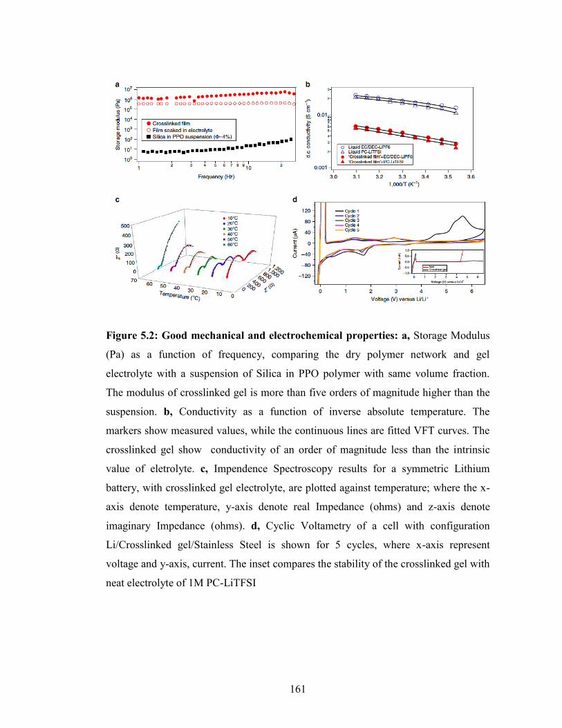
161
Figure 5.2: Good mechanical and electrochemical properties: a, Storage Modulus
(Pa) as a function of frequency, comparing the dry polymer network and gel
electrolyte with a suspension of Silica in PPO polymer with same volume fraction.
The modulus of crosslinked gel is more than five orders of magnitude higher than the
suspension. b, Conductivity as a function of inverse absolute temperature. The
markers show measured values, while the continuous lines are fitted VFT curves. The
crosslinked gel show conductivity of an order of magnitude less than the intrinsic
value of eletrolyte. c, Impendence Spectroscopy results for a symmetric Lithium
battery, with crosslinked gel electrolyte, are plotted against temperature; where the x-
axis denote temperature, y-axis denote real Impedance (ohms) and z-axis denote
imaginary Impedance (ohms). d, Cyclic Voltametry of a cell with configuration
Li/Crosslinked gel/Stainless Steel is shown for 5 cycles, where x-axis represent
voltage and y-axis, current. The inset compares the stability of the crosslinked gel with
neat electrolyte of 1M PC-LiTFSI

162
Steel. Measurements were performed between -0.2V to 6.5V and a scan rate of 1mV/s
was employed. Figure 5.2(d) shows the current as a function of Voltage for the CNPC
electrolyte at different cycle numbers, while the inset shows the equivalent first cycle
results obtained using a PC-1MLiTFSI liquid electrolyte. The significant current peaks
at ~ -0.2V vs. Li+/Li and +0.2V vs. Li+/Li indicate that plating and stripping of Li ions
onto/from stainless steel42. As previously reported43, a passivation layer is formed on
the Li metal surface at 4.1V vs. Li+/Li, indicated by the current peak, which disappears
in subsequent cycles. The CNPC electrolyte also shows a high stability window, with
cathodic stability of at least 5V vs. Li+/Li, which is superior to what is observed for a
PC-LiTFSI liquid electrolyte.
Figure 5.4.3 Analyzing stability of Lithium electrodeposition using crosslinked
membranes
Figure 5.3 (a, d) report results from a so-called ‘strip-plate test’ in which symmetric
Li|Li cells are charged and discharged sequentially for a period of three hours. The
voltage profiles for liquid electrolytes are shown in Supplementary Figure 5.6. It is
clear that cells containing the CNPC electrolyte exhibit remarkably high cycling
stability in comparison to standard cells with the same liquid electrolyte infused in the
CNPC membrane. At a current density of 0.20mA/cm2, the cells show stable voltage
profiles for more than 500 hours. In comparison, a control symmetric cell with the
same electrolyte and without the cross-linked membranes fails within 60 hours (see
Supplementary Figure 5.6). At a higher current density of 1mA/cm2, the cells run for
more than 120 hours, whereas, the voltage profile for the control cell is already

163
unstable from the first cycle of the test. Figure 5.3 reports the morphology of the
Lithium anode surface using Scanning Electron Microscopy (SEM) after 100 hours of
cycling for both types of cells discussed above. At a current density of 0.20mA/cm2,
the anode surface is smooth with only sporadic patches of rough deposits (Figure
5.3(b)) for cells based on the CNPC electrolyte. In contrast, clear sharp dendrites are
formed on the surface of the anode cycled in the control liquid electrolyte (Figure
5.3(c)). For cells cycled at the higher current density of 1mA/cm2 the SEM images
show that after 100 hours, a dendritic structure is visibly present on the anode surface
cycled in both the CNPC and control liquid electrolytes, however, the control cells
display comparatively sharper and much larger dendrites.
In an LMB, electrolytes are also prone to degradation as a result of parasitic chemical
and electrochemical reactions with the reactive lithium metal anode. Uneven
electrodeposition exacerbates this failure mode by creating fresh surface for additional
reactions. The coulombic efficiency is an important parameter that allows these effects
to be quantified and tracked from cycle to cycle; it can therefore be considered a
surrogate measure of the stability of the Solid Electrolyte Interface (SEI) on the
lithium metal anode. Several recent studies have considered methods for improving
the stability of the SEI layer using protective films on Li anodes.44,45 Procedures
ranging from deployment of sacrificial, surface-reactive additives in liquid
electrolytes,7,9,46–48 to use of electrolytes saturated with salt 49 have been reported to be
effective in stabilizing lithium metal.

164
We performed cycling studies in which a fixed amount of Li is transferred from a
lithium metal electrode onto a stainless-steel substrate and quantify the recovery in the
reverse process when Li is stripped from the substrate to determine the coulombic
efficiency. Understanding that surface protection of lithium is required for meaningful
coulombic efficiencies in LMBs, the control measurements were performed using
liquid electrolytes comprised of PC containing 1wt% LiNO3, and 2wt% vinylene
carbonate (VC) as an additive, which are reported to form a stable SEI on Li.48 In
contrast to the symmetric cell studies discussed in the previous section where
reasonable cycling was possible in liquid electrolytes in cells using O-ring style
separators, we discovered that the poor adhesion between deposited lithium and the
stainless steel counterelectrode caused lithium to separate and become electrically
disconnected from the stainless steel substrate, resulting in poor columbic efficiencies.
Replacing the O-rings with a conventional Celgard separator eliminated this problem.
The coulombic efficiency obtained in this manner is plotted in Figure 5.3(g) as a
function of cycle number at a current density of 0.25mA/cm2 for the control liquid
electrolyte and for CNPC electrolytes (CNPC membranes soaked in the control liquid
electrolyte). A typical voltage-capacity curve measured at the 40th cycle of these
measurements is provided in the Supplementary Figure 5.8. PC is known to form a
very unstable SEI layer, yielding a low coulombic efficiency (~75%)50, however, it is
evident that the additives improve the efficiency to over 90% both in liquid PC and in
the CNPC electrolytes. Nevertheless, it is seen from Figure 5.3(g) that the neat
electrolyte fails to sustain high coulombic efficiency beyond 45 cycles, while the

165
Figure 5.3: Inhibiting dendrites and enabling smooth electrodeposition: a, Plate-
Strip cycles for a symmetric cell comprising of crosslinked gel electrolyte is shown at
a current density of 0.20 mA/cm2, it shows stable performance for over 500 hours. b,
The morphology of Lithium metal anode after 100 hours of cycling of with the
crosslinked gel electrolyte is shown, where very smooth surface is observed. c,
Similarly, the morphology of Lithium metal anode neat electrolyte is shown, where
dendritic structures of Lithium is seen to have formed. d, Volatge vs. time plots at 1.00
mA/cm2 for crosslinked gel based cells are shown, the cells show no sign of short
circuit for at least 120 hours. e, The post mortem analysis shows scatters of Lithium
structures. f, The Lithium surface after 100 hours of cycling shows dense dendrites
that are capable of shorting the cells. All white scale bars measure 20 microns. g,
Electrochemical tests with Li| electrolyte| Stainless Steel configuration at a current
density of 0.25mA/cm2 comparing coulombic efficiency as a function of cycle
numbers for pristine and crosslinked gel electrolytes with 2%(vol.) V.C. and 1%(wt.)
LiNO3 additive.

166
CNPC electrolytes maintain high coulombic efficiency for at least 100 cycles. This
can be rationalized by our earlier observation of smoother electrodeposition in the
latter electrolytes, which helps in preventing the rupture and reformation of SEI layer
in successive charge and discharge cycles.
Polarization experiments at a fixed current density provide a more aggressive protocol
for evaluating stability of lithium electrodeposition. Figure 5.4(a) compares the cell
lifetimes obtained using strip-plate and polarization measurements. A typical voltage
vs. time curve is shown in the Supplementary Figure 5.9. It is again apparent that the
CNPC electrolytes enable cells that deliver over two orders of magnitude
improvement in lifetime. The short circuit times (TSC ) deduced for both the
polarization test and strip-plate cycling studies can be fitted with a power-law function
of the form, TSC = A.J-K, where J is the current density and A is a transport coefficient.
The power law exponents for the strip-plate and polarization measurements are,
respectively, 1.84 and 1.35; consistent with previous reports14,43.
Figure 5.4(a) compares the short circuit time from our plate-strip and polarization
experiments with results from a wide variety of literature studies. For example, Rosso
et al.51 studied the stability of lithium electrodeposition in high-molecular-weight
poly(ethylene oxide) containing lithium salt at 90OC. The figure shows that at
equivalent current densities, the cross-linked nanocomposite electrolyte based cells
register substantially higher short circuit times in comparison to those obtained in the
polymer electrolytes studied by Rosso et al. Figure 5.4(a) also reports results from the
work of Liu et al.39,40,52 who performed electrochemical experiments in visualization

167
cells in which surface modified silica-PEO based nanocomposite electrolytes, solid
polymer electrolytes comprised of PEOxLiTFSI repeating units, and combinations of
the two were used to stabilize deposition in lithium metal batteries at elevated
temperature; from Sannier et. al.53 who performed symmetric cell studies using gel
polymer membranes based on PEO and PVdF-HFP polymers; and from Khurana et
al.14 using cross-linked PEO-PE-PEO polymers. It is important to note that all of these
experiments were performed at elevated operating temperature between 60OC and
90OC to overcome the poor room temperature ionic conductivity of the electrolyte
materials. It is apparent from the figure that the CNPC electrolytes deliver as good or
better performance than all of these other studies with the important difference that the
experiments the CNPC electrolytes were all performed at room temperature! Finally,
Figure 5.4(a) reports results from simple liquid electrolytes (here termed Neat
electrolytes) and other state-of-art nanocomposite and polymer based electrolytes
reported previously to be effective inhibitors of dendrite growth in LMBs operated at
room temperature. Comparison of these results with those obtained in the present
study also show that cells that utilize CNPC electrolytes exhibit superior ability to
stabilize electrodeposition of Li than any of the other room-temperature
electrolyte/separator materials.11,54 On the basis of these results, we therefore conclude
that the CNPC electrolytes reported in the present study are promising candidates
towards the goal of dendrite-free room temperature LMBs.
To further characterize the galvanostatic performance of our electrolyte materials,
LMBs were constructed in which metallic lithium was paired with Lithium Titanium

168
Figure 5.4: High short circuit time and good cyclic stability: a, Short circuit time of crosslinked gel electrolytes compared with other state of art battery performance. Red squares and red circles indicate the Tsc for strip-plate test and polarization test in this work respectively. The black filled symbols represent polarization tests done at Room Temperature, while the open symbols represent elevated temperature experiments. Black closed triangles represent Silica tethered with Imidazolium (Si-IM-IL) and Piperidinium Ionic Liquid (Si-PP-IL) at various volume fractions of Silica, indicated in parenthesis11. Black closed diamonds indicate anion tethered hybrid silica nanocomposites54. The high temperature data include crosslinked PE-PEO solid polymer with different plasticizer content given in parenthesis14. Other data points are PVdF-HFP/PEO composite53, high molecular weight polymer51, silica –polymer composite40, polymer with ionic liquid39 as well as their combination52. The blue symbols indicate neat/pristine electrolyte systems. b, Cycling Performance for Li| crosslinked gel| LTO is shown at 1C (0.50mA/cm2). The inset shows the voltage profiles of the same. c, Cyclic performance for Li| crosslinked gel| LFP at C-rate of C/2 (0.25mA/cm2) is shown, with inset showing voltage profiles. In last two figures, closed black symbols indicate discharge capacity, open black indicate charge capacity. The red triangles denote coulombic efficiency.

169
Oxide (LTO) and Lithium Iron Phosphate (LFP) as the cathode. For these studies,
CNPC membranes were soaked in the commonly used EC: DEC (1v: 1v) electrolyte
solvent mixture containing 1M LiPF6 salt. Again the CNPC electrolytes exhibited
mS/cm level room-temperature ionic conductivities, allowing the batteries to be
operated at room temperature. For practical applications, it is important for a battery to
have high capacity for large number of cycles, even at high current densities. Figure
5.4(b) reports the cycling performance of Li|CNPC+EC:DEC1MLiPF6|LTO cells at a
current density of 0.5mA/cm2. The batteries retain high capacity for at least 150
cycles. Figure 5.4(c) reports the performance of a battery where we paired metallic
lithium with a LFP cathode in the CNPC electrolyte. At a current density of
0.25mA/cm2, the battery retains a capacity of over 120mAh/cm2 upto 150 cycles. The
inset of the figures shows the voltage profiles of the respective cells exhibit clear
plateaus and low IR losses. These results clearly show that the CNPC electrolytes have
good compatibility with lithium metal and with conventional high-performance
intercalating cathodes and anodes. This makes them promising candidate materials for
LMBs in which a metallic lithium anode is paired with conventional intercalating
cathodes.
5.5 Discussion
Our findings provide a novel pathway towards nanostructured membranes in which
chemistry introduced on the surface of nanoparticles can be internalized in the pores
for regulating ion and mass transport. Here we illustrate the approach using hairy
nanoparticles that can be cross-linked with rigid polymers to create ion-conducting

170
membranes with good mechanical properties. Because each particle is functionalized
with up to 55 reactive groups, this allows one to achieve highly cross-linked materials
at very low particle contents. This makes it possible to create electrolyte membranes
with both high mechanical modulus (GN = 1MPa) and high, liquid-like ionic
conductivity (σo = 5mS/cm) at ambient temperature, where traditional high modulus
electrolyte systems fail to maintain high conductivity. The cross-linked polymer
nanoparticle composite (CNPC) electrolytes are shown to be exceptionally effective in
promoting smooth, dendrite-free electrodeposition of lithium metal at intermediate
current densities. Comparison of the lithium metal anode lifetimes achievable in the
new materials with those reported for other polymer, block-copolymer, cross-linked
polymers and polymer-nanoparticle composites show that CNPC systems are the most
promising for room-temperature LMB systems. Further, it is shown that these
materials work efficiently in LMBs based on low-voltage LTO and intermediate
voltage LFP cathodes, where they can be reversibly cycled with high discharge
capacity for over 150 cycles, at high current densities.
Acknowledgments
This work was supported by the National Science Foundation, Award No. DMR–
1006323 and by Award No. KUS–C1018–02, made by King Abdullah University of
Science and Technology (KAUST). Small-angle X-ray Scattering facilities available
through the Cornell High Energy Synchotron Source (CHESS) were used in the study.
CHESS is supported by the NSF & NIH/NIGMS via NSF award DMR-1332208.

171
REFERENCES
1. Armand, M. & Tarascon, J.-M. Building better batteries. Nature 451, 652–7
(2008).
2. Dresselhaus, M. S. & Thomas, I. L. Alternative energy technologies. Nature
414, 332–7 (2001).
3. Dunn, B., Kamath, H. & Tarascon, J.-M. Electrical energy storage for the grid:
a battery of choices. Science 334, 928–35 (2011).
4. Tarascon, J. M. & Armand, M. Issues and challenges facing rechargeable
lithium batteries. Nature 414, 359–67 (2001).
5. Kim, H., Jeong, G., Kim, Y.U., Kim, J.H., Parke, C.M., and Sohn, H.J.,
Metallic anodes for next generation secondary batteries. Chem. Soc. Rev. 42,
9011–34 (2013).
6. Xu, W. et al. Lithium metal anodes for rechargeable batteries. Energy Environ.
Sci. 7, 513 (2014).
7. Pieczonka, N. P. W. et al. Impact of lithium bis(oxalate)borate electrolyte
additive on the performance of high-voltage spinel/graphite Li-ion batteries. J.
Phys. Chem. C 117, 22603–22612 (2013).

172
8. Li, B., Xu, M., Li, T., Li, W. & Hu, S. Prop-1-ene-1,3-sultone as SEI formation
additive in propylene carbonate-based electrolyte for lithium ion batteries.
Electrochem. commun. 17, 92–95 (2012).
9. Aurbach, D. et al. On the use of vinylene carbonate (VC) as an additive to
electrolyte solutions for Li-ion batteries. Electrochim. Acta 47, 1423–1439
(2002).
10. Lu, Y., Das, S. K., Moganty, S. S. & Archer, L. A. Ionic liquid-nanoparticle
hybrid electrolytes and their application in secondary lithium-metal batteries.
Adv. Mater. 24, 4430–5 (2012).
11. Lu, Y., Korf, K., Kambe, Y., Tu, Z. & Archer, L. A. Ionic-Liquid-Nanoparticle
Hybrid Electrolytes: Applications in Lithium Metal Batteries. Angew. Chemie
126, 498–502 (2014).
12. Bouchet, R. et al. efficient electrolytes for lithium-metal batteries. Nat. Mater.
12, 452–457 (2013).
13. Gurevitch, I. et al. Nanocomposites of Titanium Dioxide and Polystyrene-
Poly(ethylene oxide) Block Copolymer as Solid-State Electrolytes for Lithium
Metal Batteries. J. Electrochem. Soc. 160, A1611–A1617 (2013).
14. Khurana, R., Schaefer, J. L., Archer, L. A & Coates, G. W. Suppression of
lithium dendrite growth using cross-linked polyethylene/poly(ethylene oxide)

173
electrolytes: a new approach for practical lithium-metal polymer batteries. J.
Am. Chem. Soc. 136, 7395–402 (2014).
15. Tu, Z., Kambe, Y., Lu, Y. & Archer, L. A. Nanoporous Polymer-Ceramic
Composite Electrolytes for Lithium Metal Batteries. Adv. Energy Mater. 4, n/a–
n/a (2014).
16. Tikekar, M. D., Archer, L. A. & Koch, D. L. Stability Analysis of
Electrodeposition across a Structured Electrolyte with Immobilized Anions. J.
Electrochem. Soc. 161, A847–A855 (2014).
17. Fuller, J., Breda, A. C. & Carlin, R. T. Ionic Liquid-Polymer Gel Electrolytes.
J. Electrochem. Soc. 144, 8–11 (1997).
18. Zhang, J., Sun, B., Huang, X., Chen, S. & Wang, G. Honeycomb-like porous
gel polymer electrolyte membrane for lithium ion batteries with enhanced
safety. Sci. Rep. 4, 6007 (2014).
19. Stephan, A. M. Review on gel polymer electrolytes for lithium batteries. Eur.
Polym. J. 42, 21–42 (2006).
20. Cheng, X.-B., Peng, H.-J., Huang, J.-Q., Wei, F. & Zhang, Q. Dendrite-Free
Nanostructured Anode: Entrapment of Lithium in a 3D Fibrous Matrix for
Ultra-Stable Lithium-Sulfur Batteries. Small 1–7 (2014).

174
21. Hallinan, D. T., Mullin, S. A., Stone, G. M. & Balsara, N. P. Lithium Metal
Stability in Batteries with Block Copolymer Electrolytes. J. Electrochem. Soc.
160, A464–A470 (2013).
22. Hallinan, D. T. & Balsara, N. P. Polymer Electrolytes. Annu. Rev. Mater. Res.
43, 503–525 (2013).
23. Singh, M. et al. Effect of Molecular Weight on the Mechanical and Electrical
Properties of Block Copolymer Electrolytes. Macromolecules 4578–4585
(2007).
24. Croce, F., Appetecchi, G. B., Persi, L. & Scrosati, B. Nanocomposite polymer
electrolytes for lithium batteries. Nature 394, 456–458 (1998).
25. Tang, C., Hackenberg, K., Fu, Q., Ajayan, P. M. & Ardebili, H. High Ion
Conducting Polymer Nanocomposite Electrolytes Using Hybrid Nanofillers.
Nano Lett. 1152–1156 (2012).
26. Bertasi, F. et al. Single-Ion-Conducting Nanocomposite Polymer Electrolytes
for Lithium Batteries Based on Lithiated-Fluorinated-Iron Oxide and
Poly(ethylene glycol) 400. Electrochim. Acta (2015).
27. Agrawal, A., Choudhury, S. & Archer, L. A. A highly conductive, non-
flammable polymer-nanoparticle hybrid electrolyte. RSC Adv, 5, 20800. (2015).

175
28. Croce, F., Sacchetti, S. & Scrosati, B. Advanced, lithium batteries based on
high-performance composite polymer electrolytes. J. Power Sources 162, 685–
689 (2006).
29. Balazs, A. C., Emrick, T. & Russell, T. P. Nanoparticle polymer composites:
where two small worlds meet. Science 314, 1107–10 (2006).
30. Krishnamoorti, R. Strategies for Dispersing Nanoparticles in Polymers. MRS
Bull. 32, (2007).
31. Smith, G. D. & Bedrov, D. Dispersing nanoparticles in a polymer matrix: are
long, dense polymer tethers really necessary? Langmuir 25, 11239–43 (2009).
32. Chandran, S., Begam, N., Padmanabhan, V. & Basu, J. K. Confinement
enhances dispersion in nanoparticle-polymer blend films. Nat. Commun. 5,
3697 (2014).
33. Patra, T. K. & Singh, J. K. Polymer directed aggregation and dispersion of
anisotropic nanoparticles. Soft Matter 10, 1823–30 (2014).
34. Srivastava, S., Agarwal, P. & Archer, L. A. Tethered nanoparticle-polymer
composites: phase stability and curvature. Langmuir 28, 6276–81 (2012).
35. Litschauer, M., Peterlik, H. & Neouze, M.-A. Nanoparticles/Ionic Linkers of
Different Lengths: Short-Range Order Evidenced by Small-Angle X-ray
Scattering. J. Phys. Chem. C 113, 6547–6552 (2009).

176
36. Litschauer, M., Puchberger, M., Peterlik, H. & Neouze, M.-A. Anion metathesis
in ionic silica nanoparticle networks. J. Mater. Chem. 20, 1269 (2010).
37. Moganty, S. S. et al. Ionic Liquid-Tethered Nanoparticle Suspensions: A Novel
Class of Ionogels. Chem. Mater. 24, 1386–1392 (2012).
38. Stone, G. M. et al. Resolution of the Modulus versus Adhesion Dilemma in
Solid Polymer Electrolytes for Rechargeable Lithium Metal Batteries. J.
Electrochem. Soc. 159, A222–A227 (2012).
39. Liu, S. et al. Lithium Dendrite Formation in Li/Poly(ethylene oxide)–Lithium
Bis(trifluoromethanesulfonyl)imide and N-Methyl-N-propylpiperidinium
Bis(trifluoromethanesulfonyl)imide/Li Cells. J. Electrochem. Soc. 157, A1092
(2010).
40. Liu, S. et al. Effect of nano-silica filler in polymer electrolyte on Li dendrite
formation in Li/poly(ethylene oxide)–Li(CF3SO2)2N/Li. J. Power Sources 195,
6847–6853 (2010).
41. Schaefer, J. L., Moganty, S. S., Yanga, D. A. & Archer, L. A. Nanoporous
hybrid electrolytes. J. Mater. Chem. 21, 10094 (2011).
42. Georén, P. & Lindbergh, G. On the use of voltammetric methods to determine
electrochemical stability limits for lithium battery electrolytes. J. Power
Sources 124, 213–220 (2003).

177
43. Lu, Y., Tu, Z. & Archer, L. A. Stable lithium electrodeposition in liquid and
nanoporous solid electrolytes. Nat. Mater. 13, 961–969 (2014).
44. Zheng, G. et al. Interconnected hollow carbon nanospheres for stable lithium
metal anodes. Nat. Nanotechnol. 9, 618–623 (2014).
45. Luo, W. et al. A Thermally Conductive Separator for Stable Li Metal Anodes.
Nano Lett. 15 (9), 6149–6154 (2015).
46. Li, W. et al. The synergetic effect of lithium polysulfide and lithium nitrate to
prevent lithium dendrite growth. Nat. Commun. 6, 7436 (2015).
47. Pires, J. et al. Role of propane sultone as additive to improve the performance
of lithium-rich cathode material at high potential. RSC Adv. 5, 42088-42094
(2015).
48. Guo, J., Wen, Z., Wu, M., Jin, J. & Liu, Y. Vinylene carbonate–LiNO3: A
hybrid additive in carbonic ester electrolytes for SEI modification on Li metal
anode. Electrochem. commun. 51, 59–63 (2015).
49. Qian, J. et al. High rate and stable cycling of lithium metal anode. Nat.
Commun. 6, 6362 (2015).
50. Ding, F. et al. Dendrite-free lithium deposition via self-healing electrostatic
shield mechanism. J. Am. Chem. Soc. 135, 4450–6 (2013).

178
51. Rosso, M., Gobron, T., Brissot, C., Chazalviel, J.-N. & Lascaud, S. Onset of
dendritic growth in lithium/polymer cells. J. Power Sources 97-98, 804–806
(2001).
52. Liu, S. et al. Effect of co-doping nano-silica filler and N-methyl-N-
propylpiperidinium bis(trifluoromethanesulfonyl)imide into polymer electrolyte
on Li dendrite formation in Li/poly(ethylene oxide)-Li(CF3SO2)2N/Li. J.
Power Sources 196, 7681–7686 (2011).
53. Sannier, L., Bouchet, R., Rosso, M. & Tarascon, J. M. Evaluation of GPE
performances in lithium metal battery technology by means of simple
polarization tests. J. Power Sources 158, 564–570 (2006).
54. Schaefer, J. L., Yanga, D. A. & Archer, L. A. High Lithium Transference
Number Electrolytes via Creation of 3-Dimensional, Charged, Nanoporous
Networks from Dense Functionalized Nanoparticle Composites. Chem. Mater.
25, 834–839 (2013).

179
APPENDIX
Supplementary Information for Chapter 5
Supplementary Figures
Supplementary Fig. 5.1: Fourier Transform- Infrared Spectroscopy (FTIR)
Characterization of the Reaction Scheme: The reaction process is confirmed by the
IR-peak transition involved in urethane reaction. The –NCO peak of the PPO
Diisocyanate disappears, while characteristic peaks of –NH vibration and shift in the –
C=O peak appear because of the urethane bond formation in the final product.

180
Supplementary Fig. 5.2: TGA Analysis: The initial silica content in the hairy
nanoparticle (Si-PEO) was 83%, which reduces to 6% silica in the final product of
crosslinked film. Thus, the non-conducting entity in the entire material is remarkably
low, in-spite of having decent mechanical strength. Further soaking the CNPC in 1M
electrolytes comprising of PC-LiTFSI, reduces the silica content close to 2%, as
shown in the inset of the figure. Also, it is evident that the film is remarkably stable,
such that there is degradation of the product up-to 120OC, where PC starts to degrade.

181
Supplementary Fig. 5.3: DSC Characterization of: The glass transition temperature
of the PPO polymer increases from -63OC to -42OC due to the reduction of free
volume as the chains are constricted due to the crosslinking. However, the crosslinked
film is still in amorphous state at room temperature where it is used as electrolyte in
battery systems. The amorphous nature of the polymer membrane enables higher ionic
conductivity compared to other high MW PEO based electrolyte at room temperature.

182
Supplementary Fig. 5.4: TEM Analysis: The inter-particle spacing in the
crosslinked polymer is estimated by graphical analysis of TEM micrograph.

183
Supplementary Fig. 5.5: Equivalent Electric Circuit for the Impedance
Spectroscopy results: The Nyquist plot obtained by the measurement of the
Impedance at a wide range of frequency can be fitted by an equivalent circuit shown
above. The bulk resistance and the interfacial resistance, thus obtained are plotted
against temperature; and it is seen that the interfacial resistance is always higher than
the bulk resistance, which indicates interface limited ion transfer.

184
Supplementary Fig. 5.6: Strip-Plate measurement of a symmetric Lithium cell
without CNPC separator: The voltage profile of a control cell (Li/PC+LiTFSI/Li) is
plotted against time. a, it is seen that at current density of 0.20mA/cm2 about 55 hours
of charging-discharging, the voltage profile gets distorted and the voltage range drops
down which is a signature of dendrite induced short circuit. b, at current density of
1.00mA/cm2, the voltage profile is unstable even at the start of cycle.
(a)
b

185
Supplementary Fig. 5.7: SEM image of Pristine Lithium: Surface of Lithium is
presented in order to compare the changes in surface morphology after cycling using
neat and crosslinked gel based electrolytes. (Scale bar is 10 microns)
10 µm

186
Supplementary Fig. 8: Coulombic Efficiency Test using Li| electrolyte| Stainless
Steel configuration showing 40th cycle: Batteries with crosslinked gel electrolyte and
pristine PC-LiTFSI were cycled at 0.25mA/cm2. It is seen that at the 40th cycle, the
neat electrolyte exhibits deposition at a much lower voltage and also low coulombic
efficiency compared to the crosslinked gel electrolyte.

187
Supplementary Fig. 5.9: Polarization curve of symmetric Lithium cell with
crosslinked gel electrolyte: A symmetric Lithium cell consisting of crosslinked gel
electrolyte is charged constantly at a current density of 0.12mA/cm2. It is seen that the
cell successfully depositing Li ion onto the anode surface for about 400 hours before
failing, indicated by drop in the voltage profile.

188
Supplementary Fig. 5.10: Cycling Performance using LTO cathode: It is seen that
using the crosslinked gel electrolyte, a LTO based battery cycles well for over 150
cycles at a high current density of 1mA/cm2

189
Supplementary Fig. 5.11: Cycling Performance of LiFePO4 battery using
crosslinked gel electrolyte: It is seen that at a C-rate of C/3, the battery cycles with
minimum fade for at least 100 cycles.

190
Supplementary Tables Supplementary Table 5.1: Content of different components at successive
synthesis stage: The weight percent of the Silica, PEO, PPO, electrolyte is given in
table. It is seen that ultimately in the crosslinked gel electrolyte contains as low as 2%
silica, still having a relatively high mechanical modulus.
Type of product Si-PEO Si-PEO-PPO Si-PEO-PPO-Electrolyte
Component Wt. % Wt. % Wt. %
Silica 83 6 2
PEO 17 1.3 0.4
PPO - 92.7 30.9
Electrolyte - - 66.7

191
Supplementary Table T2: VFT parameters of the different electrolyte
configuration: σ=Αexp(-B/(T-TO)), where A is the pre-exponential factor
corresponding to conductivity at infinite temperature, B is the Activation Energy and
TO is the reference temperature.
Parameters A (S/cm)
B (K)
TO (K)
LiPF6-EC/DEC 0.045 56.9 237
LiTFSI-PC 0.044 61 239
Crosslinked film-LiPF6-EC-DEC 0.239 870.5 84.3
Crosslinked film-LiTFSI-PC 0.237 891.5 85

192
Supplementary Methods:
The size of clusters was obtained by fitting the SAXS data with Beaucage unified
equation [1] as shown below.
First two terms (Guinier and power law) contribute to the scattering for spheres in a
dilute suspension with radius 53 pa R ~ 4-5 nm and power law exponent 1p (~4). A
and B are the Guinier and Porod scaling factors. The last term contributes to the
scattering from the fractal objects in the low q regime with 53fractal cR R ~ 51-72 nm
with a power exponent 2p ~2, indicating the fractals to be mass fractals. Since the low
q regime has only the power law scattering no Guinier term has been included
suggesting that the fractalR obtained from the fitting will be the lower bound as exact
dimension cannot be determined. C is the pre-factor factor for the power law
scattering in the low q. Absence of any additional structure contribution in
intermediate to high q suggests that the particles are reasonably far apart.
Supplementary References
1. Beaucage, G., Small-angle scattering from polymeric mass fractals of arbitrary
massfractal dimension. Journal of Applied Crystallography 29 (2), 134-146
(1996)
1 2,3 3,
2 2 2 26 6( ) exp exp3 3
ip p
p c i
p pi
i
qR qRq R q R
I q A Berf C erfq q
§ · § ·§ · § ·¨ ¸ ¨ ¸¨ ¸ ¨ ¸§ · § ·¨ ¸ ¨ ¸© ¹ © ¹ � � � �¨ ¸ ¨ ¸¨ ¸ ¨ ¸¨ ¸ ¨ ¸© ¹ © ¹¨ ¸ ¨ ¸
¨ ¸¨ ¸ © ¹© ¹
¦

193
CHAPTER 6
CONFINING ELECTRODEPOSITION OF METALS IN STRUCTURED
ELECTROLYTES

194
6.1 Abstract
Electrochemical cells based on alkali metal (Li, Na) anodes have attracted significant
recent attention because of their promise for producing large increases in gravimetric
energy density for energy storage in batteries. To facilitate stable, long-term operation
of such cells a variety of structured electrolytes have been designed in different
physical forms, ranging from soft polymer gels to hard ceramics, including porous
ceramics that host a liquid or molten polymer in their pores. In almost every case, the
electrolytes are reported to be substantially more effective than anticipated by early
theories in improving uniformity of deposition and lifetime of the metal anode. These
observations have been speculated to reflect the effect of electrolyte structure in
regulating ion transport to the metal electrolyte interface, thereby stabilizing metal
electrodeposition processes at the anode. Here, we create, and study model structured
electrolytes composed of covalently linked polymer grafted nanoparticles that host a
liquid electrolyte in the pores. The electrolytes exist as free-standing membranes with
effective pore-size that can be systematically manipulated through straightforward
control of the volume fraction of the nanoparticles. By means of physical analysis and
direct visualization experiments we report that at current densities approaching the
diffusion limit, there is a clear transition from unstable to stable electrodeposition at Li
metal electrodes in membranes with average pore sizes below 500 nm. We show that
this transition is consistent with expectations from a recent theoretical analysis that
takes into account local coupling between stress and ion transport at metal-electrolyte
interfaces.

195
6.2 Significance
Electrochemical cells based on lithium and sodium metal anodes are considered
among the most versatile platforms for high-energy electrical energy storage.
Unfortunately, unstable dendritic metal deposition at currents below the diffusion limit
lead to premature cell failure by internal short-circuits. In a volatile electrolyte, the
ohmic heat generated by these shorts pose significant safety risks. The manuscript
reports that electrodeposition of metals can be stabilized by confining ion transport to
length scales below a few hundred nanometers. It is also shown that dendrite growth
can be arrested in electrolytes with mechanical moduli well below that of the metal.
This finding contradicts current orthodoxy, which holds that solid-state electrolytes
with moduli higher than the metal are required for preventing dendrite growth.
6.3 Introduction
Rechargeable electrochemical cells based on alkali metal anodes provide opportunities
to substantially push the energy storage limits of batteries. Such cells achieve this feat
both by increasing the amount of electrical energy that can be stored on a mass or
volume basis at the anode and by enabling more flexible material choices for the
cathode.1–6 Parasitic reactions between the chemically reactive anode7–11 and
proliferation of rough, dendritic/mossy electrodeposition at the metal anode during
battery recharge have been reported to reduce stability of the cells by increasing the
likelihood of failure by internal short circuits and by increasing the surface area of
reactive metals in contact with electrolytes.12,13

196
The stability analysis of electrodeposition reported by Monroe and Newman14,15 (MN)
is to our knowledge the first to employ continuum modeling of ion transport processes
and mechanics in bulk electrolytes to predict morphological transitions at a metal
anode. This work showed that marginal stability is achieved at any current density in
an electrolyte with mechanical modulus about twice that of the metal electrode. One
study using block copolymer electrolytes based on hard polystyrene and ion
conductive poly(ethylene oxide) segments to systematically adjust the electrolyte
modulus provided early support for this prediction.16–19 This finding, however, stands
in contrast to a large and growing body of recent experimental reports which show that
rough deposition of metals can be inhibited in gel-like electrolytes20,21, cross-linked
polymer electrolytes18,22,23 and in ion conducting polymer electrolytes,24–26 all with
mechanical moduli three or more orders of magnitude below that of the metal
electrode. Recently, Zhao et al.27 showed that a composite polymer electrolyte with
immobilized ions and ceramic fillers can indeed inhibit dendrites at ambient
conditions. Even more dramatic are reports which show that dendrite-induced short-
circuits in lithium and sodium batteries can be delayed or even eliminated at low and
moderate current densities in liquid electrolytes in which a fixed fraction of anions is
maintained at the interface,28–33 or in liquid electrolytes in which halide ions are
present at the electrode-electrolyte interface.11,34–37 Essentially nothing is known about
the working mechanisms by which such low-modulus materials prevent metal dendrite
proliferation at either low or high current densities, relative to the diffusion limiting
current J*, and a variety of qualitative arguments have been proposed to explain their
working mechanism.

197
The present study is motivated by recent theoretical work by Tikekar et al.,7,38 which
extended the MN analysis to consider the effect of local stress-transport coupling with
ion migration profiles and the impact such coupling has on stability of metal
electrodeposition. This analysis shows that at current densities below J*, stable
electrodeposition of metals can be achieved under a broad range of conditions,
including in electrolytes with shear moduli as low as 0.1MPa (i.e. more than four
orders of magnitude lower than that of the metal electrode). Another conclusion from
the analysis is that electrolytes created by hosting simple liquids in porous materials
should be able to prevent rough electrodeposition of any metal when the average pore
size of the host falls-below a certain critical electrolyte-dependent value. This
prediction is important because it means that solid-state electrolytes are not required to
stabilize electrodeposition at metal anodes in batteries; it is also testable. Here, we
design structured electrolytes based on cross-linked nanoparticle-polymer hybrid
membranes in which the effective pore size can be facilely manipulated by changing
the volume fraction of particles in the precursor material. We also use these
electrolytes to systematically investigate the effect of electrolyte network structure and
mechanical properties on the stability of metal deposition at currents close to the
critical current density, J*. The study takes advantage of an optical visualization
technique that allows time-dependent changes in morphology of the metal-electrolyte
interface to be directly imaged. Used in combination with the analysis of Tikekar et
al.38, these efforts are shown to lead to a comprehensive understanding of how and
why structured electrolytes that do not meet the MN modulus criteria are able to
prevent metal dendrite proliferation.

198
6.4 Materials and Methods:
6.4.1 Materials
Lithium rods, Ethylene Carbonate, Dimethylene carbonate, Lithium
Hexafluorophosphate, Anydrous Copper Chloride, Dimethyl Sulfoxide, Glass fibers
Ludox SM30 colloidal silica (d=10±2 nm), poly(propylene glycol)-toluene-2,4-
diisocyante were all purchased from Sigma Aldrich. Hydoxy terminated poly
(ethylene oxide)-silane was obtained from Gelest. Copper foil was obtained from Alfa
Aesar. All the chemicals were used as received in after rigorous drying in a ~0ppm
water level and <5ppm oxygen glove box.
6.4.2 Linear Stability Analysis
The details regarding the linear stability analysis is presented in a previous paper by
Tikekar et al.38
6.4.3 Crosslinked Hairy Nanoparticles Synthesis
The reaction procedure for crosslinking between the grafted silica nanoparticles and
functionalized PPO polymer is given in a previous work.18 Different crosslinked
nanoparticles with varying pore sizes was synthesized by adjusting the ratio between
the silica nanoparticles and the PPO polymer as given in the Supplementary Table 1.
The ratio between the liquid electrolyte and the crosslinked composite was kept
constant at 2:1 by weight.
6.4.4 Dielectric Spectroscopy
The dielectric spectroscopy measurements were done using a Novocontrol N40
Broadband Dielectric instrument. The crosslinked hairy nanoparticles as well as neat
PPO (without liquid electrolyte) were casted at the center of a teflon o-ring. The

199
measurements were done in a frequency range from 10−3 to 107 Hz at various
temperatures
6.4.5 Transmission Electron Microscopy
The TEM measurements were performed to understand the nanostructure of the
crosslinked hairy nanoparticles using a FEI T12 Spirit TEM. A thin layer of the
materials was casted onto the TEM grid using chloroform as the solvent and it was
allowed to crosslink in the TEM grid. Before the measurements, the samples were
dried overnight at 60°C.
6.4.6 Scanning Electron Microscopy
SEM analysis was done using the LEO155FESEM instrument. In this experiment,
symmetric lithium coin cell was constructed using the crosslinked electrolyte (r.c.p. =
20 nm). ‘Plate-strip’ measurements were performed at a current density of 0.1
mA/cm2 for 100 hours, with each cycle comprising of 3 hours; thereafter the lithium
electrode was extracted and dried in the ante-chamber of glove-box overnight.
6.4.7 Mechanical Properties
The crosslinking process was studied mechanically by casting the precursor materials
in the rheometer with parallel-plate geometry of diameter 25mm using a ARES
Rheometer. Specifically, for time-sweep measurements, a constant strain amplitude of
5% and fixed frequency of 10Hz was applied until the storage modulus reached a
fixed value. The frequency sweep measurements were performed at a fixed strain
amplitude of 5% between 1Hz to 100Hz for all materials. All the measurements were
done without any addition of liquid electrolytes and at the same temperature value of
60°C.

200
6.4.8 Direct Visualization experiments
The visualization experiment was carried out for understanding the electrodeposition
process with various forms of electrolytes mentioned in the manuscript. In all the
measurements the ratio between the weight of the composite material and liquid
electrolyte (1M LiPF6 EC/DMC) was kept to be constant at 1:2. The details of the
visualization cell for lithium deposition measurements is presented in a previous
paper.10 The dendrite growth was done using a semi-automatic analysis in MATLAB,
where the sizes of the focused dendrites are measured over time.
6.5 Results
Figure 6.1(a) shows the synthetic route used to create cross-linked hairy nanoparticle-
based electrolytes. Briefly, silica nanoparticles (diameter ~10nm) are first grafted in
aqueous solution with an alkoxy silane terminated oligomeric polyethylene glycol
(PEO-OH, Mw = 500 g/mol). As shown in our previous work,18,39,40 the approach
produces SiO2 nanoparticles densely grafted (∑ ≈ 1 chain/nm2; from Thermal
gravimetric analysis (TGA)) with PEO chains bearing a reactive terminal hydroxyl
group. The resultant SiO2–PEO-OH nanoparticles are subsequently used as
multifunctional node points for cross-linking poly(propylene oxide) (PPO, Mw = 2000
g/mol) chains functionalized with isocyanate groups at both ends. A straightforward
calculation shows that on average there are ~300 PEO-OH molecules anchored to a
single SiO2 nanoparticle, meaning that materials with a high degree of cross-linking
are achieved. Additionally, because the PEO chains are short and the PPO linkers are
amorphous at ambient temperatures, the cross-linked materials exist as free-standing

201
membranes with high flexibility and toughness for silica content of 6.5% (by weight)
(see Figure 6.1(b)). The large number of grafting sites available on each SiO2
nanoparticle makes it possible to introduce different functionalities, including ionic
species41 or flame retardants such as phosphates 42 in the materials. Cross-linking
these nanostructures provides a facile route to nanoporous membranes in which the
surface chemistry of the pores can be manipulated for regulating the ion transport
characteristics or for preventing thermal runway in lithium batteries. Furthermore, by
varying the volume fraction of particles it is possible to systematically change the
configuration of the particle-tethered PEO and PPO chains in the cross-linked
materials to create membranes with vastly different pore sizes and mechanical
properties.
It is possible to monitor the progress of the cross-linking reaction by measuring the
time-dependent development of elasticity in the materials by means of dynamic shear
rheological measurements (Figure 6.1(c)). Specifically, we employed oscillatory shear
to continuously measure the storage and loss modulus of the initial slurry of PEO-
grafted nanoparticles and PPO-diisocyanate chains at 60qC using a small-amplitude
shear strain of 1% and a fixed oscillatory shear frequency of 10Hz. It is observed that
the storage modulus increases over time indicative of the cross-linking process, which
reaches its maximum value in about 24 hours. It is important to note that although the
chemical reaction between an isocyanate and hydroxyl group is very fast, the overall
cross-linking reaction kinetics are under diffusion control as it becomes progressively
harder for PPO chains tethered to one particle to bond to a neighboring site on another
particle to increase network elasticity. It can also be seen from Fig. 6.1(c) that the loss

202
Figure 6.1: Synthesis Crosslinked Hairy Nanoparticles: (a) Schematic showing
synthesis procedure of the crosslinked nanoparticles; (b) Photograph of the
free-standing membrane with 6.8% (by weight) silica content; (c) Time sweep
measurements under oscillatory shear at strain 1% and frequency of 10Hz at
60qC

203
modulus decreases and rolls over to very low values at long times, consistent with the
gradual loss of dissipation processes as the network becomes more fully cross-linked.
These effects are most dramatically demonstrated by comparison of the storage and
loss moduli for the unlinked PPO polymer. It is seen that whereas the loss modulus
dominates storage for the unlinked, liquid-like material, the storage modulus
dominates as cross-linking nears completion. It is remarkable that at just 6.8 w% of
SiO2 in the materials there is increment of over five orders of magnitude in modulus.
More in-depth knowledge of the configuration and dynamics of the linker polymer
chains is possible from dielectric relaxation measurements. It is known that polymers
such as poly(propylene oxide) and cis-1,4-polyisoprene possess type-A dipole that
facilitate alignment of the polymer chain end-to-end vector in the direction of an
imposed electric field; thus one can quantify the end-to-end chain relaxation from the
dielectric loss spectrum.43,44 Additionally, from the magnitude of the loss peak, one
can calculate the dielectric strength, which for flexible, amorphous chains can be used
to estimate the relative degree of chain stretch.45 Supplementary Figure 6.1(a), (b)
show the loss permittivity of the neat PPO and cross-linked PPO at various
frequencies and temperatures. The experimental data was fitted using
Havriliak−Negami (H-N) equation: ε*(ω) = ε∞ + Δε/[(1 + (iωτ)D)β ], where D and β
are associated with broadening dielectric-peaks, τ represent the H−N relaxation time,
ω is frequency, ε∞ is dielectric constant (ε′) at high frequency limit, and Δε is the
dielectric strength. The relaxation times at various temperature obtained from the H-N
fits are shown in Supplementary Figure 6.1(c). It can be seen that the relaxation time

204
for all temperatures follow Vogel–Fulcher–Tammann (VFT) model, represented by
the continuous lines in the figure, The VFT model is given as: τ =Α
exp(−B/k(T−To)), where, A is the prefactor, B is the activation energy and To is
reference temperature, shown in Supplementary Table 6.1. It can be seen that the
activation energy of the relaxation dynamics of PPO polymer increases dramatically
from 9.8 kJ/mole to 20 kJ/mole as a result of cross-linking, which is consistent with
expectations based on the molecular weight of the polymers and high levels of cross-
linking achieved.18 Comparison of the dielectric strength for the untethered and
tethered PPO indicates that the linkers are also highly stretched (shown in
Supplementary Figure 6.1(d)). For random coil type-A dielectric polymer chains, the
dielectric strength Δε is proportional to the mean squared end-to-end vector of the
polymer chain. The results in Supplementary Figure 6.1d) show that Δε measured
using the cross-linked membranes is approximately 250 times larger than the
corresponding value for the linear unlinked polymer. Considering that the molecular
weight of the PPO chains is just 2kDa, the large increases in Δε also imply that dipoles
on the particle tethered chains are also highly correlated.
The cross-linked hairy nanoparticles provide an opportunity to understand the
underlying physics of metal electrodeposition in heterogeneous environment, because
these materials serve as model nanoporous structures such that the silica nanoparticles
act as non-conductive physical barriers and the polymeric chains in the inter-particle
gaps as pathways for ion migration. In this context, the volume fraction of silica
nanoparticles in the entire composite was varied and the corresponding inter-particle
distance was estimated by assuming random closed packing (r.c.p.) arrangement of

205
spherical nanoparticles: , as reported in Supplementary
Table 6.2 for different weight fraction of silica content. We utilized Transmission
Electron Microscope (TEM) to analyze the spatial arrangement of the nanoparticles in
the polymer composite as shown in Supplementary Figure 6.2(a) for r.c.p. pore-sizes
of 20nm, 100 and 500nm. The interparticle distance of the silica nanoparticles was
furthered measured from the TEM images and the corresponding variation was fitted
to a Normal Distribution function obtained from the respective mean and standard
deviations and plotted as inset of the images. The average interparticle distances
measured from TEM is observed to be similar to r.c.p. pore sizes (Figure 6.2(a)).
However, the variance of the distribution is seen to increase with decreasing silica
volume fractions (Supplementary Figure 6.3). We furthered performed frequency
sweep measurements at a constant amplitude of 5% for different crosslinked PPO as
well as neat PPO polymer. The storage and loss modulus of obtained from the
measurements are plotted in Supplementary Figure 6.2(b) and (c), respectively. The
results show that the composite materials at all crosslinking densities have higher G’
than G”, indicating elastic behavior that is unseen at such low core volume fractions in
colloidal suspensions. The elastic modulus is seen to progressively increase with
increasing core volume fraction, the associated cage volume (kT/G’) is reported in
Figure 6.2(a). Membranes with r.c.p. pore size 20 nm show the highest shear modulus
of approximately 1MPa, while in the uncross-linked state the materials are simple
Newtonian liquid. The higher variance of spatial distribution of silica nanoparticles
and reminiscence of elasticity at low core fractions indicate that the particles form
hierarchical string-like mass fractals due to the fixed length of the crosslinker (PPO),

206
b
a
Increasing silica concentrat ion in polymer network
Figure 6.2: Characterization of pore architecture in the crosslinked structure: (a)
Comparing the pore sizes obtained from TEM as well as cage sizes obtained
from frequency sweep measurements with the random closed packing pore
sizes; (b) Schematic showing the changes in pore structures with the variation
of silica nanoparticle volume fractions. In all the sub-parts, the sample names
are characterized by the random closed packing interparticle distance between
silica nanoparticles in the composites

207
as shown in in Figure 6.2(b), also confirmed using small-angle x-ray scattering in our
previous work46.
Next, we systematically study the morphology of the lithium-electrolyte interface in
the cross-linked hairy nanoparticles soaked with liquid electrolyte using direct
visualization of the lithium metal anode during electrodeposition in an optical cell.
The cell comprises of a lithium metal and stainless-steel electrodes separated by a
chamber containing electrolyte of 1M LiPF6-EC/DMC.10 For the conditions used in
the experiments, the diffusion limited current density for the different membranes
were calculated from the measured conductivity and transference number: J* =
2zcoFDapp(taL)-1. Here, z is the charge number of cation, F is the Faraday constant, co
is salt concentration, ta is the anion transference number and L is the inter-electrode
spacing (1 mm) and Dapp is the diffusion coefficient. Using the Bruce-Vincent
method33 the transference number (see Supplementary Figure 6.4), was determined to
be 0.38 for the crosslinked nanoparticles (r.c.p. = 20 nm). The variation of
conductivity and critical current density (J*) for the crosslinked nanoparticles at
different pore sizes are reported in Supplementary Figure 6.5. It is seen that J* varies
in the range ~5 to 9 mA/cm2 for the materials studied. Using the previously reported
values of Li+ transference number (0.36) and lithium ion diffusivity (3*10-6 cm2/sec)
for 1M EC:DMC-LiPF6 electrolyte, the diffusion limited current density can be
estimated to be 9 mA/cm2 for the same inter-electrode spacing.47,48
Figure 6.3(a) reports snapshots of the negative electrode at different stages of
electrodeposition for the cases without any separator, with a commercial glass fiber
separator and crosslinked hairy nanoparticles (r.c.p. pore size = 20 nm) at a constant

208
current density of 8 mA/cm2, which 0.9 times the J* calculated for liquid electrolyte.
Through visual inspection, it is obvious that Li electrodeposition in the absence of a
separator is uneven, mossy and blackened, which is indicative of the side reactions
between electrode and electrolyte as well as porous nature of the deposited layers. At
first appearance, the deposits are already quite large, at least 100 µm in diameter,
which is much larger than typical Li dendrite nucleate sizes assumed in the literature.6
Deposition studies based on a commercial glass fiber separator shows that deposition
is relatively compact until a capacity of around 2 mAh/cm2 (i.e. approximately 10
µm/cm2 Li is transferred), where after dendritic structures develop and proliferate in
time, ultimately piercing the separator and continue their growth through the separator.
This sequence is associated with the short-circuiting phenomena described in the
introduction section and can lead to catastrophic cell failure by fire, explosion, or both.
In comparison to the cases with and without separator, the deposition pattern with the
cross-linked hairy nanoparticles display uniform deposition for entire one hour of the
charging process.
By tracking the advancing front of the Li electrode over time, it is possible to quantify
the dendrite growth as a function of time (see Figure 6.3(b)). The apparent growth rate
obtained from the initial time through the assumption of linearity is shown in the inset.
The larger sized error bars for the neat electrolyte case is a reflection of the
unevenness of electrodeposition. The apparent growth rate of dendrite in the
commercial glass fiber separator is calculated to be ~0.13 Pm/sec, while for the cross-
linked hairy nanoparticles it is estimated to be 0.03 Pm/sec which is modestly larger

209
Figure 6.3: Stability of electrodeposition by direct visualization of electrode: (a)
Snapshots of the electrode and electrolyte in every 15 minutes during charging
at the rate of 8 mA cm-2; (b) Height of dendrite at various points of the electrode
for the initial 1500 seconds, the inset compares the growth rate by assuming a
linear growth for electrodeposition at 8 mA cm-2
0 mAh cm-2 6 mAh cm-2 8 mAh cm-24 mAh cm-22 mAh cm-2
No
sepa
rato
rGl
ass
fiber
Cros
slin
ked
NP’
s
100 μm
Capacity of lithium deposited
0
0.1
0 .2
0 .3
0 .4
Grow
th r
ate
(μm
/sec
)

210
than the theoretical rate (0.011 Pm/sec) for perfectly smooth electrodeposition at 8
mAh/cm2.
This idea that one could control the stability of electrodeposition by manipulating the
nanostructure of an electrolyte (Supplementary Figure 6.6) was previously discussed
in the theoretical analysis by Tikekar et al.7,38 and has also been adapted in an adhoc
manner to explain previous experimental results.49,50 Deposition in membranes with
pores larger than the critical nucleate diameter at which electrodeposition is unstable,
is in this analysis thought to lead to unchecked growth of dendrites that penetrate
through this pores, as in the case of the glass fiber separator. In contrast, in the
crosslinked hairy nanoparticles the pore size of 20 nm is evidently much smaller than
the nucleate size leading to a significant retardation of dendrite growth. To determine
the effect of SEI formation and chemical instability on the topological features
observed during the electrodeposition process, we performed post-mortem analysis of
lithium electrode after repeated charge and discharge cycling in a coin cell.
Specifically, we utilized a symmetric lithium battery with the crosslinked nanoparticle
electrolyte (20 nm) and operated the battery at a current of 0.1 mA/cm2 for 100 hours,
with each half-cycle comprising of 3 hours, as shown in Supplementary Figure S7. We
intentionally chose low current densities for the operation to isolate the effect of
chemical and not morphological instabilities. The SEM image of the extracted lithium
metal is seen to be smooth and unperturbed (Supplementary Figure 6.8). This provides
evidence that the observed evolution of electrode surface in visualization experiment
is dominant by dendritic growth of lithium and not due to parasitic reactions at the
interface.

211
a b
Figure 6.4: Analyzing pore size dependence on dendrite growth: (a), (b) Growth
rate at different pore sizes and corresponding elastic modulus, respectively for
the crosslinked hairy nanoparticles at current density of 8 mA/cm2 as well as for
variable current densities matching 0.9 times of the limiting current densities
measured for respective samples

212
One could make these tentative ideas more concrete by interrogating the evolution of
the interface in cross-linked electrolytes in which the average pore size is
systematically varied. Supplementary Figure 6.9 show the snapshots of deposition at
same current density of 8 mA/cm2, and Supplementary Figure 6.10 report the
analytical results from such studies in which the morphology of the Li-electrolyte
interface is characterized in cross-linked nanoparticles with varying pore size (or,
weight fraction of SiO2 in the composite). The liquid electrolyte weight was
maintained to be same in all cases reported in this work, which is twice as that of the
composite weight. The results show that when the effective pore size of the membrane
is 1000 nm, dendrite growth is unimpeded and rapid. However, at high volume
fractions of silica nanoparticles corresponding to interparticle distance of order 500
nm, Supplementary Figure 6.10 shows two regimes of dendrite-growth, wherein, the
growth rate at the initial time is low, followed by an accelerated rate of dendrite
propagation at longer time. The results in Supplementary Figure 6.9 also shows that
for the membranes with 500 nm pores, dendrites with ‘needle-like’ morphology are
visible at 4 mAh/cm2, in contrast to the mossy-blackened deposited lithium apparent
when the pores are larger and in neat electrolytes. Furthermore, it is seen that in
membranes with effective pore size of around 100 nm, the deposition is similarly
restricted as for the 20 nm case, implying that there is a threshold pore size between
500 nm and 100 nm where the resistance to dendrite proliferation is large enough to
prevent growth.
Figure 6.4(a) and (b) summarizes the growth rate deduced from experiments as a
function of average membrane pore size and elastic modulus, respectively at 8

213
mA/cm2 as well as for varying current densities such that J/J* remains constant at 0.9
(see Supplementary Figure 6.5). Optical snapshots of the initial deposition and the
corresponding current densities (at J/J* = 0.9) are reported in Supplementary Figure
6.11. The experimental results reveal a sudden transition from stable deposition to
dendrite growth between 100 to 500 nm pore-size in agreement with our hypothesis
that electrodeposition stability is function of electrolyte length-scale. Also, the shear
modulus measured from rheology doesn’t have a linear relation with growth rate can
be rationalized by the fact that the crosslinked membrane is comprised of building
blocks having different inherent modulus (SiO2 and polymer). As the deposition takes
place in the inter-particle gap, the growing ‘dendrites’ only experience the modulus of
the liquid electrolyte and polymers, thus the length scale of the polymeric phase plays
a greater role than the overall modulus of the material. We also analyze the growth
rate of dendrites as a function of pore size obtained from TEM micrograph analysis as
well as the pore volume calculated from plateau modulus as kT/G’, As shown in
Supplementary Figure 6.12, a similar non-linear behavior is observed.
Figure 6.5(a) plots the perturbation growth rate versus wavelength deduced from the
analysis of Tikekar et al.38 It is seen that the growth rate is negative for small wave
lengths and goes through a maximum at a particular wavelength that decreases as the
current density approaches critical current density, J*. The first of these results can be
shown to arise from the greater influence of surface tension in suppression growth of
small dendrite nucleates, while the presence of the maximum reflects the effect of the
physical (macroscopic) dimensions of the simulation cell in restricting nucleate size
below certain limits. As the current density increases, the growth rate of the fastest

214
a b
Figure 6.5: Linear Stability analysis of dendrite growth: (a) Normalized Growth
rate of the deposited nucleate at different normalized wave numbers obtained by
linear stability analysis; (b) Maximum growth at different theoretical pore sizes
at various effective currents. The different lines in parts (a) and (b) represent
different values of J/J*

215
(most unstable) mode increases and its wavelength decreases because the interfacial
tension has to compete with progressively more aggressive electroconvection to stop
the roughening. The fastest growing mode can therefore be thought of as
representative of the typical size of dendrites that one would observe in an experiment
under similar conditions. A porous material would restrict the size of the growing
dendrite, since the deposition can only happen on length scales smaller than the pore
size. In Figure 6.5(b), we show the calculated growth rate for the fastest growing mode
as a function of the critical wavelength. For very large pores, the pore size is predicted
to have no effect on the dendrite growth, and the growth occurs more or less at the
same rate as in the absence of the porous material. For smaller pores however, the pore
diameter restricts the sizes of the dendrites that can form in them, causing the growth
rate of the fastest mode to plummet. Below a certain size, there can be no unstable
deposition, as surface tension adequately competes with current density driven
dendritic growth at all possible length scales. This critical pore size decreases with
current density due to the requirement of a higher contribution from surface tension as
seen in Supplementary Figure 6.13. The inset in Figure 6.13 plots the analogous
growth rate deduced from experiments as a function of membrane pore size for a fixed
current density, J/J* ~0.9. The experimental results show a similar trend as calculated
from the linear stability analysis, wherein there is sudden transition from stable
deposition to dendrite growth. The transition point from the theoretical prediction
corresponding to non-zero growth is ~1.6 Pm, while the experiments indicate the
crossover between 100-500 nm pore-size as previously mentioned in Figure 6.4(a).
Considering the variety of sources of error in comparing the experiments and theory,

216
including the tortuosity of the pores in the cross-linked materials, the polydispersity of
the particle size, uncertainty in the value of the Li transference number under the
conditions of the experiments48, and the deviation from linearity in calculation of
initial growth rate, the agreement between the theoretical and observed transition is
fair.
6.5 Conclusion
In conclusion, we utilize a crosslinked network by covalently linking polymer-grafted
nanoparticles, where varying the volume fraction of the nanoparticles in the composite
can conveniently change the effective pore size. It was shown that these crosslinked
nanoparticles when used as gel electrolytes showed stable electrodeposition in contrast
to mossy and dendritic morphology for cases without separator and with glass fibers
respectively. We performed visualization experiments for different pore sizes
determined by volume fractions to demonstrate that below 500 nm, the deposition is
smooth and compact, while dendritic for other cases. These experimental observations
were rationalized using linear stability analysis of dendrite growth at different
perturbation length scale representing pore diameter of the electrolytes. It was
understood that below the limiting current density, the electrodeposition can be
stabilized by implementing a separator with pore-size lower than the length scale of
the most unstable nucleate. Overall, this work will provide guidelines for designing
solid state electrolytes and separators for metal-based batteries.

217
Acknowledgements
This work was supported by the National Science Foundation, Division of Materials
Research, through Award No. DMR–1609125.

218
REFERENCES
1. Lin, D., Liu, Y. & Cui, Y. Reviving the lithium metal anode for high-energy
batteries. Nat. Nanotechnol. 12, 194–206 (2017).
2. Cheng, X. et al. A Review of Solid Electrolyte Interphases on Lithium Metal
Anode. Adv. Sci. 3, 1–20 (2016).
3. Cheng, X.-B., Zhang, R., Zhao, C.-Z. & Zhang, Q. Toward Safe Lithium Metal
Anode in Rechargeable Batteries: A Review. Chem. Rev. 117, 10403–10473
(2017).
4. Ma, L., Hendrickson, K. E., Wei, S. & Archer, L. A. Nanomaterials: Science
and applications in the lithium–sulfur battery. Nano Today 10, 315–338 (2015).
5. Zhang, W. et al. Design Principles of Functional Polymer Separators for High-
Energy, Metal-Based Batteries. Small 1703001–n/a
doi:10.1002/smll.201703001
6. Wei, S., Choudhury, S., Tu, Z., Zhang, K. & Archer, L. A. Electrochemical
Interphases for High-Energy Storage Using Reactive Metal Anodes. Acc. Chem.
Res. (2017). doi:10.1021/acs.accounts.7b00484
7. Tikekar, M. D., Archer, L. A. & Koch, D. L. Stabilizing electrodeposition in
elastic solid electrolytes containing immobilized anions. Sci. Adv. 2, (2016).
8. Chazalviel, J.-N. Electrochemical aspects of the generation of rampified
metallic electrodeposits. 42, 7355–7367 (1990).
9. Bai, P., Li, J., Brushett, F. R. & Bazant, M. Z. Transition of lithium growth
mechanisms in liquid electrolytes. Energy Environ. Sci. 9, 3221–3229 (2016).

219
10. Choudhury, S. et al. Electroless Formation of Hybrid Lithium Anodes for Fast
Interfacial Ion Transport. Angew. Chemie Int. Ed. 56, 13070–13077 (2017).
11. Choudhury, S., Wei, S., Ozhabes, Y., Gunceler, D. & Nath, P. Designing Solid-
liquid Interphases for Sodium Batteries. Nat. Commun. 8, (2017).
12. Wood, K. N. et al. Dendrites and Pits: Untangling the Complex Behavior of
Lithium Metal Anodes through Operando Video Microscopy. ACS Cent. Sci. 2,
790–801 (2016).
13. Zheng, G. et al. Interconnected hollow carbon nanospheres for stable lithium
metal anodes. Nat. Nanotechnol. 9, 618–623 (2014).
14. Monroe, C. & Newman, J. The Effect of Interfacial Deformation on
Electrodeposition Kinetics. J. Electrochem. Soc. 151, A880 (2004).
15. Monroe, C. & Newman, J. The Impact of Elastic Deformation on Deposition
Kinetics at Lithium/Polymer Interfaces. J. Electrochem. Soc. 152, A396 (2005).
16. Stone, G. M. et al. Resolution of the Modulus versus Adhesion Dilemma in
Solid Polymer Electrolytes for Rechargeable Lithium Metal Batteries. J.
Electrochem. Soc. 159, A222–A227 (2012).
17. Agrawal, A., Choudhury, S. & Archer, L. a. A highly conductive, non-
flammable polymer–nanoparticle hybrid electrolyte. RSC Adv. 5, 20800–20809
(2015).
18. Choudhury, S., Mangal, R., Agrawal, A. & Archer, L. A. A highly reversible
room-temperature lithium metal battery based on crosslinked hairy
nanoparticles. Nat. Commun. 6, 10101 (2015).
19. Lu, Y., Korf, K., Kambe, Y., Tu, Z. & Archer, L. a. Ionic-Liquid-Nanoparticle

220
Hybrid Electrolytes: Applications in Lithium Metal Batteries. Angew. Chemie
126, 498–502 (2014).
20. Zhang, J., Sun, B., Huang, X., Chen, S. & Wang, G. Honeycomb-like porous
gel polymer electrolyte membrane for lithium ion batteries with enhanced
safety. Sci. Rep. 4, 6007 (2014).
21. Stephan, a. M. Review on gel polymer electrolytes for lithium batteries. Eur.
Polym. J. 42, 21–42 (2006).
22. Wu, H. et al. Stable Li-ion battery anodes by in-situ polymerization of
conducting hydrogel to conformally coat silicon nanoparticles. Nat. Commun. 4,
1943 (2013).
23. Khurana, R., Schaefer, J. L., Archer, L. A. & Coates, G. W. Suppression of
lithium dendrite growth using cross-linked polyethylene/poly(ethylene oxide)
electrolytes: a new approach for practical lithium-metal polymer batteries. J.
Am. Chem. Soc. 136, 7395–7402 (2014).
24. Porcarelli, L., Gerbaldi, C., Bella, F. & Nair, J. R. Super Soft All-Ethylene
Oxide Polymer Electrolyte for Safe All-Solid Lithium Batteries. Sci. Rep. 6,
19892 (2016).
25. Long, L., Wang, S., Xiao, M. & Meng, Y. Polymer electrolytes for lithium
polymer batteries. J. Mater. Chem. A 4, 10038–10069 (2016).
26. Gurevitch, I. et al. Nanocomposites of Titanium Dioxide and Polystyrene-
Poly(ethylene oxide) Block Copolymer as Solid-State Electrolytes for Lithium
Metal Batteries. J. Electrochem. Soc. 160, A1611–A1617 (2013).
27. Zhao, C.-Z. et al. An anion-immobilized composite electrolyte for dendrite-free

221
lithium metal anodes. Proc. Natl. Acad. Sci. 114, 11069 LP-11074 (2017).
28. Tu, Z. et al. Designing Artificial Solid-Electrolyte Interphases for Single-Ion
and High-Efficiency Transport in Batteries. Joule (2017).
doi:https://doi.org/10.1016/j.joule.2017.06.002
29. Choudhury, S. et al. Designer interphases for the lithium-oxygen
electrochemical cell. Sci. Adv. 3, (2017).
30. Ma, L., Nath, P., Tu, Z., Tikekar, M. & Archer, L. A. Highly Conductive,
Sulfonated, UV-Cross-Linked Separators for Li–S Batteries. Chem. Mater. 28,
5147–5154 (2016).
31. Lu, Y. et al. Stable Cycling of Lithium Metal Batteries Using High
Transference Number Electrolytes. Adv. Energy Mater. 5, 1402073 (2015).
32. Oh, H. et al. Poly(arylene ether)-Based Single-Ion Conductors for Lithium-Ion
Batteries. Chem. Mater. 28, 188–196 (2016).
33. Bouchet, R. et al. Single-ion BAB triblock copolymers as efficient electrolytes
for lithium-metal batteries. Nat. Mater. 12, 452–457 (2013).
34. Choudhury, S. & Archer, L. A. Lithium Fluoride Additives for Stable Cycling
of Lithium Batteries at High Current Densities. Adv. Electron. Mater. 1–6
(2015). doi:10.1002/aelm.201500246
35. Lu, Y., Tu, Z. & Archer, L. A. Stable lithium electrodeposition in liquid and
nanoporous solid electrolytes. Nat. Mater. 13, 961–969 (2014).
36. Seh, Z. W., Sun, J., Sun, Y. & Cui, Y. A Highly Reversible Room-Temperature
Sodium Metal Anode. ACS Cent. Sci. 1, 449–455 (2015).
37. Zhang, X., Cheng, X., Chen, X., Yan, C. & Zhang, Q. Fluoroethylene

222
Carbonate Additives to Render Uniform Li Deposits in Lithium Metal Batteries.
Adv. Funct. Mater. 27, 1605989 (2017).
38. Tikekar, M. D., Archer, L. A. & Koch, D. L. Stability Analysis of
Electrodeposition across a Structured Electrolyte with Immobilized Anions. J.
Electrochem. Soc. 161, A847–A855 (2014).
39. Choudhury, S., Agrawal, A., Kim, S. a & Archer, L. a. Self-Suspended
Suspensions of Covalently Grafted Hairy Nanoparticles. Langmuir 31, 3222–
3231 (2015).
40. Choudhury, S., Agrawal, A., Wei, S., Jeng, E. & Archer, L. A. Hybrid Hairy
Nanoparticle Electrolytes Stabilizing Lithium Metal Batteries. Chem. Mater.
28, 2147–2157 (2016).
41. Wei, S. et al. Highly Stable Sodium Batteries Enabled by Functional Ionic
Polymer Membranes. Adv. Mater. 29, 1605512 (2017).
42. Stalin, S., Choudhury, S., Zhang, K. & Archer, L. A. Multifunctional Cross-
Linked Polymeric Membranes for Safe, High-Performance Lithium Batteries.
Chem. Mater. 30, 2058–2066 (2018).
43. Agarwal, P., Kim, S. A. & Archer, L. A. Crowded, Confined, and Frustrated:
Dynamics of Molecules Tethered to Nanoparticles. Phys. Rev. Lett. 109,
258301 (2012).
44. Ding, Y. et al. Dielectric Spectroscopy Investigation of Relaxation in C 60 -
Polyisoprene Nanocomposites. 3201–3206 (2009). doi:10.1021/ma8024333
45. Adachi, K. & Kotaka, T. Dielectric normal mode relaxation. Prog. Polym. Sci.
18, 585–622 (1993).

223
46. Choudhury, S., Mangal, R., Agrawal, A. & Archer, L. A. A highly reversible
room-temperature lithium metal battery based on crosslinked hairy
nanoparticles. Nat. Commun. 6, 10101 (2015).
47. Nyman, A., Behm, M. & Lindbergh, G. Electrochemical characterisation and
modelling of the mass transport phenomena in LiPF6-EC-EMC electrolyte.
Electrochim. Acta 53, 6356–6365 (2008).
48. Valoen, L. O. & Reimers, J. N. Transport Properties of LiPF6-Based Li-Ion
Battery Electrolytes. J. Electrochem. Soc. 152, A882 (2005).
49. Tu, Z., Nath, P., Lu, Y., Tikekar, M. D. & Archer, L. A. Nanostructured
Electrolytes for Stable Lithium Electrodeposition in Secondary Batteries. Acc.
Chem. Res. 48, 2947–2956 (2015).
50. Tu, Z. et al. Nanoporous Hybrid Electrolytes for High-Energy Batteries Based
on Reactive Metal Anodes. Adv. Energy Mater. 7, 1602367 (2017).
51. Rosso, M., Gobron, T., Brissot, C., Chazalviel, J.-N. & Lascaud, S. Onset of
dendritic growth in lithium/polymer cells. J. Power Sources 97–98, 804–806
(2001).

224
APPENDIX
Supplementary Information for Chapter 6
Supplementary Figure 6.1: Dielectric Relaxation of Crosslinked Hairy
Nanoparticles: (a), (b) Dielectric Permittivity at various temperatures fitted with the
H-N model for Neat PPO and crosslinked hairy nanoparticles, respectively; (c)
Polymer relaxation time as a function of temperatures fitted with a VFT model; (d)
comparison between the dielectric strength between the neat PPO and crosslinked
PPO, the symbols are same as in part c.
d
b a

225
Supplementary Figure 6.2: Characterization of pore architecture in the
crosslinked structure: (a) TEM micrographs of crosslinked nanoparticles. The
scale bar represents 200 nm. From left to right, the samples are r.c.p. pore sizes
20 nm, 100 nm and 500 nm. (b) Storage Modulus and (c) Loss Modulus
obtained through frequency sweep measurements at strain of 5% for different
crosslinked samples and neat PPO at 60qC

226
Supplementary Figure 6.3: Normal Distribution of interparticle distances obtained
by analysis of TEM images for crosslinked hairy nanoparticles with different random
closed packing pore sizes

227
Supplementary Figure 6.4: Polarization of a symmetric lithium cell using the
crosslinked hairy nanoparticle electrolyte (r.c.p.=20nm) soaked with the electrolyte
1M EC/DMC LiPF6 at 20mV. The inset shows the impedance results before and after
polarization.

228
Supplementary Figure 6.5: Room temperature conductivity and limiting current
density variation with different pore sized membranes. The arrows show the
corresponding values for a neat electrolyte of 1M EC/MC LiPF6.

229
Supplementary Figure 6.6: Schematic representing the idea that the pore size of the
electrolyte/separator is important and related to the stability of electrodeposition. In
this figure, the crosslinked nanoparticles have random closed packing pore size of 20
nm

230
Supplementary Figure 6.7: Charge and discharge cycles in a symmetric lithium coin
cell using the crosslinked hairy nanoparticles electrolyte with pore size of 20 nm. The
battery was operated at a current density of 0.1 mA/cm2 with each half cycle is 3hour
long.

231
Supplementary Figure 6.8: (a), (b) SEM images of lithium electrode surface before
and after cycling in a symmetric lithium cell for 100 hours at 0.1 mA/cm2.
a c Before After

232
Supplementary Figure 6.9: Electrodeposition with different pore size of the
crosslinked nanoparticles: Snapshots of the electrode and crosslinked
electrolyte with pore sizes of 1000, 500 and 100nm in every 15 minutes during
charging at the rate of 8 mA cm-2

233
Supplementary Figure 6.10: Height of dendrite at various points of the electrode for the initial 1500 seconds, the inset compares the growth rate by assuming a linear growth for the visualization experiment in Figure S9 at a current density of 8 mA cm-2;

234
Supplementary Figure 6.11: (a) Snapshots of electrodeposition with different
crosslinked membrane pore sizes at variable current density such that the J/J* is
maintained at 0.9 for each case; (b) Height of dendrite as a function of time for
different samples. The absolute values of current densities are reported in the label that
correspond to J/J = 0.9. The inset shows the comparision of the dendrite growth rates
for the respective pore sizes reported in the main figure.
a b
0 mins 30 mins15 mins
1000
nm50
0nm
100n
m
Cros
slin
ked
Hairy
Nan
opar
ticle
s-po
re s
ize
Time of lithium deposition
100 μm
0
0.1
0.2
Grow
th r
ate
(μm
/sec
)

235
Supplementary Figure 6.12: Pore size dependence of dendrite growth at a current
density of 8 mA/cm2, where the pore size is obtained from the TEM analysis. The
inset shows the growth rate as a function of pore volume obtained from the plateau
modulus using the equation (kT/G’)

236
Supplementary Figure 6.13: Critical pore size, representative of crossover from
positive to zero growth rate, at various normalized current density. The inset
show the same graph in semi-logarithmic scale
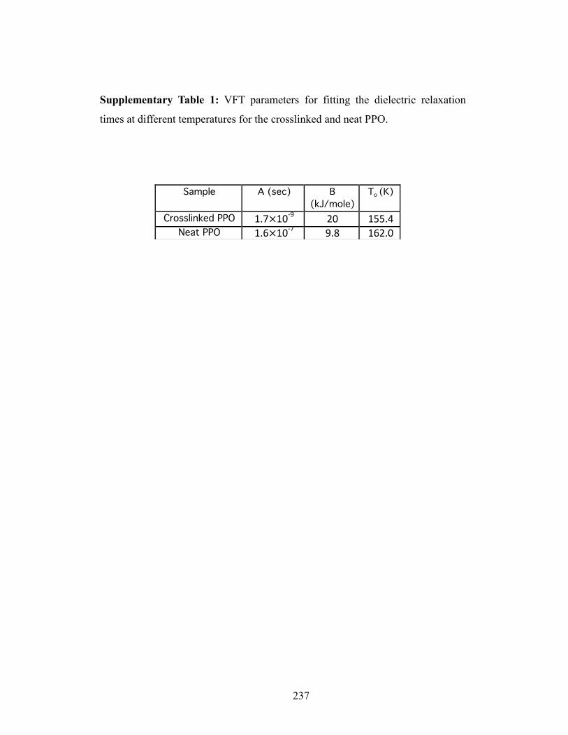
237
Supplementary Table 1: VFT parameters for fitting the dielectric relaxation
times at different temperatures for the crosslinked and neat PPO.

238
Supplementary Table 6.2: Weight fraction of silica nanoparticles
corresponding to the effective pore size obtained by the random packing
fraction spherical particles

239
Chapter 7
Soft Colloidal Glasses as Solid-state Electrolytes

240
7.1 Abstract
Solid state electrolytes are regarded as an attractive alternative to liquid electrolytes in
lithium batteries because of their intrinsic safety features and mechanical strength,
however maintaining high bulk and interfacial ion fluxes in scalable electrolyte
chemistries remains a significant challenge. In this work, we report on synthesis and
electrochemical features of a class of solid state hybrid polymer electrolytes comprised
of silica nanoparticles with grafted poly(ethylene oxide) chains. By regulating the salt
content in the materials, we find that it is possible to drive microstructural changes,
including nanoparticle arrangements, to achieve appreciable levels of room
temperature ionic conductivity in a solid-state polymer composite. Additionally, we
show that rationally designed salt additives can be used to create cathode-electrolyte
interphases (CEI) that increase the oxidative stability of PEO-based electrolytes. In so
doing, we report that solid-state lithium batteries comprised of a high-voltage nickel
manganese cobalt oxide cathode, a metallic Li anode, and a solid state hybrid polymer
electrolyte can be cycled stably with high levels of reversibility.
7.2 Introduction
Rechargeable batteries that utilize a metallic lithium anode simultaneously offer
opportunities and challenges as reversible electrochemical storage systems.1–5 Lithium
has the highest electronegativity and lowest atomic radius among other metals,
however a major drawback is the propensity of the metal to form unstable, dendritic
deposits during battery recharge, which produce premature battery failure by internal
short-circuits or by voltage runaway when the deposited lithium reacts with electrolyte

241
to form a thick, ion-retarding interphase. The ohmic heat generated by Li short circuits
in a conventional liquid electrolyte poses a serious impediment to progress for at least
three inter-related reasons.6–8 First a consequence of the flammability of the liquid
electrolytes in current use is that release of such heat in a closed electrochemical cell
would invariable end in fire, explosion, or both. Second, the relatively low melting
point (Tm = 180oC) of metallic lithium means that heat produced from a localized short
can quickly destabilize the structural integrity of the electrode, causing catastrophic
cell failure by thermal runaway. Finally, the intrinsic high reactivity with and
exothermic reactions of metallic Li with commonly used fire-fighting reagents means
that highly specialized procedures would be required to successfully intervene to stop
a lithium metal battery fire.
Solid state electrolytes are attractive candidates for lithium metal cells both because of
their non-flammable characteristics and the potential to eliminate leakage, meaning
that cells in a wider range of form factors are possible.9–11 Additionally, a solid-state
electrolyte can limit growth of Li dendrites and may limit transport of reactive species
to a thin boundary region near the interface, localizing parasitic reactions between a Li
anode and electrolyte components. The work by Li et al.12 provide the most
compelling demonstration of how these features of a solid-state electrolyte can be used
to advantage. Specifically, the authors show that a micro-lithium battery comprised of
metallic lithium anode, a Nickel Manganese Cobalt Oxide (NCM) cathode, and a
glassy Lithium Phosphorus Oxynitride (LiPON) solid electrode can be cycled stably
for at least 10,000 cycles with minimal loss of capacity. Notwithstanding intense

242
research by research teams world-wide, it has been a daunting challenge to achieve
similar stability in larger scale versions of these cells. Myriad challenges ranging from
the low bulk ionic conductivity of LiPON, its low mechanical toughness, and poor
interfacial contact have been reported.13–20 Recently, Han et al.21 has demonstrated that
some of these challenges can be overcome in solid-state batteries in which alumina-
coated lithium is used in tandem with a Li7La2.75Ca0.25Zr1.75Nb0.25O12 (LLCZN) garnet-
type solid electrolyte, but these cells face other challenges associated with cost of the
electrolyte, environmental stability of the electrolyte under conditions typically used
for battery assembly, mechanical instability of the alumina coating layer, poor
interfacial ion transport at phase boundaries between the solid-state electrolyte and
intercalating cathodes, and the tendency of Li to form three-dimensional, dendritic
deposits that appear to grow along the grain boundaries of the solid-state electrolyte.
Solid electrolytes based on amorphous or semi-crystalline polymers, most notably
poly(ethylene oxide) (PEO), have been investigated for decades because of their
flexible mechanics, straight forward manufacturability, and ability to transport lithium
ions in both amorphous and crystalline forms.22,23 Perhaps, the greatest challenge in
solid electrolytes common in both ceramics and polymers is the poor interfacial
contact between the solid electrode and electrolyte and many recent articles have
focused on developing novel strategies to ensure unrestricted electron and ion
transport in such interfaces.24–26 Solid polymer electrolytes are problematic, however,
because of their poor oxidative stability, strong coordination with Li and low
molecular mobility, which make them unsuitable for either high-voltage or high-power

243
cells capable of room temperature operation. Infusing inorganic fillers in the PEO
electrolyte has attracted significant interest as a facile strategy for simultaneously
increasing electrolyte modulus and fraction of high-conductivity amorphous phases in
the polymer, potentially breaking the usual modulus-conductivity tradeoff.7,11,27,28
However, at high loading of fillers, new challenges associated with aggregation and
phase separation of the polymer and particle phases obscure these benfits.7,29,30
In this work, we report what is to our knowledge the first example of a solid-state
polymer electrolyte that offers the combination of oxidative stability, excellent
mechanical properties, and high-enough ion mobility to enable stable operation of a
lithium metal battery at 25oC. Composed of short (Mw = 5KDa) PEO chains covalently
grafted to SiO2 nanostructures, the electrolytes exhibit soft glassy behaviors, including
existence of a yield stress that allows them to flow in response to an external load and
to vitrify when the load is removed. We demonstrate the practical utility of these soft
glassy electrolytes in electrochemical cells in which a metallic lithium anode is paired
with a Nickel Cobalt Manganese Oxide (NCM) cathode. Further, it is shown that the
oxidative instability of ether-based electrolytes at a high voltage cathode and
morphological instability of Li during battery recharge can be simultaneously
addressed in a simple solid-state electrolyte design.
7.3 Results And Discussion
7.3.1 Synthesis and Chemical Analysis
Figure 7.1 shows the schematic of the solid-state electrolyte design used in the study.
Specifically, we synthesize silanized poly(ethylene oxide) by the reaction of amine-

244
Figure 7.1: (a) Schematic of silica nanoparticle (25nm) and silane- functionalized
polyethylene oxide (5000Da) involved in the covalent grafting process; (b) Hairy
nanoparticles blended with LiTFSI salt to form electrolytes; (c) Cartoon showing the soft
glassy electrolyte sandwiched between two electrodes

245
functionalized PEO (5KDa) with 3-(Triethoxysilyl)propyl isocyanate (in 1:1 molar
basis) in anhydrous chloroform.31 Thereafter, silane-PEO is covalently grafted on the
surface of silica nanoparticles (25nm) in aqueous media (Figure 7.1(a)). A rigorous
washing process is carried out to expel the free polymer chains from the grafted
nanoparticles. The presence of free chains in the composite is a concern because it can
trigger similar adverse effects to those reported in plasticized solid polymer
electrolytes, where free molecules migrate to the electrode-electrolyte interface to
participate in parasitic reactions, similar to what is observed in liquid electrolytes. The
self-suspended materials produced by this synthesis protocol are mixed with
Bis(trifluoromethane) sulfonimide lithium salt (LiTFSI) at different ratios to provide a
cation source in the composite (Figure 7.1(b)). The SiO2-PEO/LiTFSI composite
forms the entire soft glassy electrolyte (SGE) composition (see Figure 7.1(c)). To
understand the relationship between salt composition, physico-chemical, and transport
properties of the SGE, we created SiO2-PEO/LiTFSI electrolytes with different salt
concentrations. In so doing it is possible to vary the ratio of Li+ cation and ethylene
oxide (EO) units in the composite from r = 0 to r = 0.2.
Figure 7.2 reports results from Fourier Transform- Infrared Spectroscopy (FTIR)
measurements on the soft glassy electrolytes. The major differences in the FTIR
spectra occur in the ‘finger-print’ region ranging from wavelength 900cm-1 to 1500cm-
1. Among the most obvious observations from these spectra is that absence of
contamination associated with water absorption in the materials.32,33 It is also seen that
there are several IR bands corresponding to similar vibrations in pure PEO (r = 0) and
LiTFSI. The intensity of the –CF bond stretch at 1175cm-1 can be utilized to

246
Figure 7.2: Transmitted infrared wave as a function of wavenumber obtained using
FTIR. The different r’s represent the ratio between lithium ions and ethylene oxide
monomers in the glassy electrolyte

247
understand molecular structuring in the salt in the SGE. At ratios, r = 0, 0.00625 and
0.0125, the peak at 1175cm-1 is absent. This observation is consistent with a model in
which all Li+ cations and TFSI- anions are dissociated and coordinated with PEO
moieties in the composite. Further complexation of LiTFSI (r = 0.025 and 0.05) leads
to the appearance of the 1175cm-1 peak. At higher salt contents (r = 0.10 and 0.20) the
intensity of the peak rises, implying that the LiTFSI forms aggregates in the composite
with a low degree of dissociation, and consequently low fractions of mobile ions for
charge transport in the electrolyte. These observations suggest that r = 0.025 and 0.05
are close to the optimum salt concentrations for the studied SGE electrolytes as nearly
complete salt dissociation is promoted by the particle tethered PEO chains.
7.3.2 Calorimetry and Ion Transport
The molecular structure of the SGE can be further analyzed using Differential
Scanning Calorimetry (DSC). Figure 7.3(a) reports the gravimetric heat flow as a
function of temperature for SGE with salt concentration ranging from r = 0 to 0.2. The
sharp singlet peak at ~54qC for the r = 0 sample is an indication of a lone crystallite
structure in contrast to three melting peaks reported for free PEO polymer.31,32 It can
be seen that for samples with LiTFSI salt, the thermogram still maintains a singular
peak, however with differing intensities. Supplementary Figure 7.1 reports the melting
temperatures (Tm) for the different LiTFSI: EO ratios. Interestingly, it is seen that the
Tm is maintained very close to ~54qC for SPE samples ranging from r = 0 to r = 0.025,
although the intensity is seen to go down due to the decrease in the overall content of
PEO moieties. The low degree of variation in the melting temperature in this range is

248
Figure 7.3: (a) Thermogram showing gravimetric heat flow as a function of
temperature; (b) VFT fitted experimental data of conductivity in the temperature range
above melting.

249
thought to reflect the minimum influence of the salt in disrupting the crystallite
structures of PEO. In other words, the interaction of LiTFSI with PEO in this range are
ionic and effective in dissociating Li and TFSI ions in the salt, but appear to have no
effect on the PEO crystallite size. At higher salt contents, there is a stiff drop in the Tm
at r = 0.05 to Tm = ~40qC, corresponding to this change, the crystallization peak in
Figure 7.3(a) also significantly broadens in comparison to the lower or zero salt
concentration. The decrease in Tm provides evidence of molecular interaction between
LiTFSI and PEO groups. At r = 0.10 and r= 0.20, no melting transition is observed,
implying that interactions with the salt completely disrupt crystallization of PEG
chains tethered to the SiO2 nanocores. Taken together, these observations imply that r
= 0.05 is a critical point in that it heralds a transition from less disruptive ionic to more
disrupting molecular interactions between ions in the salt and tethered PEO chains.
The molecular structure and ionic transport in an electric field can be further inferred
using conductivity measurements of these composite materials. Supplementary Figure
7.2 reports the d.c. conductivity obtained using Dielectric Spectroscopy performed
over a wide temperature range, plotted in Arrhenius form, for SGE ranging from r =
0.0125 to r = 0.2. It is known that although PEO molecules can transport ions in
amorphous as well as crystalline states, the transport timescales are considerably
different. The conductivity values for r = 0.0125, 0.025 and 0.05 are consistent with
this understanding and reveal an abrupt change in slope at 48qC, 36qC and 24qC,
respectively. This observation is also in agreement with the DSC results, which reveal
a crystallization transition in the materials. We isolated the temperature range from
48qC to 120qC for the measurements and fitted the measured conductivities with a

250
Vogel–Fulcher–Tammann (VFT) model, V = Α exp(−Ea/R(T−To)); where A is the
prefactor, Ea is the apparent activation energy for ion transport, R is universal gas
constant and To is the shift temperature. That the VFT model provides a good fit to the
data points in this range (see Figure 7.3(b)) indicates the absence of any thermal
degradation of the material or temperature-induced abnormalities in ion transport. The
fitting parameters are given in Supplementary Table 7.1. It is important to note that the
previously observed temperature-induced jamming in the self-suspended hairy
nanoparticles appears to have no noticeable effect on ionic motion.34–37 Figure 7.3(b)
further shows that the ionic conductivity at r = 0.05 is higher than the values measured
at all other Li: EO ratios in the measured temperature range (see Supplementary
Figure 7.3). The maxima in the conductivity in a material that is evidently still semi-
crystalline at low temperature provides support to our earlier suggestion that at this
salt concentration the tethered PEO chains provide maximum dissociation of ion pairs
in the LiTFSI salt. On this basis, one could further conclude that the salt concentration
at lower ratios is insufficient to produce full complexation with all the available ether-
oxygens, while at higher than r = 0.05, LiTFSI partially exist as undissociated and
non-conducting ion-pairs. For this reason, we chose r = 0.05 as the optimum
electrolyte composition for the electrochemical studies discussed next.
7.3.3 Structure Analysis and Rheology
The bulk scale (nm-Pm) characteristics of SPEs are dominated by structural
contributions from the SiO2 nanoparticle cores. For this reason we used small-angle X-
ray scattering and oscillatory shear rheology to analyze the electrolytes.

251
Figure 7.4: (a) Structure Factor obtained from SAXS analysis as a function of
radius normalized wave vector; (b) Interparticle distance obtained from the first
peak as well as value of S(q) as qÆ0 for different salt compositions.

252
Supplementary Figure 7.4 reports the scattered X-ray intensities plotted against the
wave vector q, for measurements performed at 90qC. Several features of the intensity
profile can be used to understand the structure of these materials. At high q, the I(q)
decay as the fourth power of the wave vector (I(q) ~ q-4) with repeated oscillations,
indicating that the particles are spherical in shape. Further at low q, the I(q) is
independent of q, denoting the absence of long range density fluctuations and structure
in the materials.38–40 Both characteristics are indicative of well-dispersed particles.
Figure 7.4(a) reports the structure factor (S(q)) plotted as a function of wave vector
normalized by the particle radius ~12.5nm. Remarkably, in the limit as qÆ0, S(q) is
seen to be significantly lower than previously obtained results for hard sphere
suspensions. This behavior has been reported previously and reflects the effect of
space-filling constrains on the tethered polymer chains which drive hyperuniformity in
the materials, such that S(q=0) Æ0.41,42 Figure7.4(b) reports S(q ~ 0) for the different
salt concentrations investigated. The results show there are no noticeable differences
in S(0) until r = 0.05, however, upon increasing the salt concentration beyond this
value, there is a jump in S(0), reminiscence of long-range ordering. This finding lends
support to our earlier inference that above the critical salt concentration LiTFSI is no
longer associated with PEO chains and instead occupies space between the silica
nanoparticles, reducing the strength of the space-filling constraint on grafted polymer
chains. The location of the peaks in the S(q) (see Figure 7.4(a)) confirms this point.
Specifically, the center-to-center distance between the silica nanoparticles can be
estimated from the location of the first peak S1, plotted in Figure 7.4(b). It is seen to
rise steeply beyond r = 0.05 consistent with the existence of LiTFSI as undissociated

253
Figure 7.5: (a), (b) Frequency sweep and amplitude sweep measurements obtained from
oscillatory shear measurements, respectively at 90°C. The frequency sweep were done at
strain = 0.1% and amplitude sweep at 𝛚 = 10% ; (c) Plateau modulus as strain Æ 0 from
different compositions of glassy electrolytes; (d) Dissipation energy obtained by calculating
the area under the curve of G” maxima, obtained by lognormal fitting.

254
salt clusters in the materials. It has been previously reported that the first peak of the
structure factor (S1) signifies the steric repulsions and the second peak (S2) reflect the
entropic attractions in these materials.31 Consistent with previous results using
covalently grafted particles, the S1 peak height is much larger than that of S2, in
contrast to their ionic counterparts; also signifying that the ionic linkages formed due
to the salts do not significantly alter the macroscopic distribution of the nanoparticles.
We performed oscillatory shear rheology on these materials to understand the
relationships between their dynamics and bulk transport properties. Results from
oscillatory shear measurements at a fixed shear strain (J = 0.1%) and variable dynamic
frequency (Z) and at a fixed frequency (Z = 10 s-1) and variable strain amplitude are
reported in Figure 7.5(a) and 7.5(b), respectively. All measurements were performed
at 90qC. Interestingly, for all salt compositions, the storage modulus (G’) dominates
the loss modulus (G”) in the low-strain, linear viscoelastic regime, indicating the
materials possess solid-like, elastic consistency. Large Amplitude Oscillatory Shear
(LAOS) measurements (Figure 5(b)) show that the materials are in fact soft glasses.43–
45 At low shear strain, G’ >> G” and nearly independent of Z (Figure 7.5a) and J
(Figure 7.5b). In contrast at higher shear strain, G’ decreases with increasing strain,
while G” initially rises, then falls less rapidly than G’. As a result G” displays a local
maximum, crosses G’, and ultimately becomes larger than G’ at high shear strains.
This transition of the materials from solid-like (G’ dominant) to liquid-like (G”
dominant) consistencies at higher strains, along with the appearance of the G”
maximum at an intermediate shear strain are all well-known traits of soft glasses.
They are known to arise from arrested motion or caging of the SiO2 cores by the

255
interdigitated tethered PEO molecules followed by strain-induced breakdown of the
cages, yielding particles that slide past each other dissipating energy as a result of
frictional contacts between the dislocated corona polymer chains.31,40
Figure 7.5(c) reports the normalized elastic modulus obtained from the results in
Figure 7.5(a) at different salt concentrations. Here G’ is normalized by the Brownian
Stress kT/R3, such that values above unity imply that the stresses produced by caging
are sufficient to prohibit uncorrelated, random motion of the cores. The results show
that at all salt concentrations <G’/(kT/R3)> is significantly larger than unity meaning
that the particle motions are completely arrested by the interdigitated PEO corona. The
PEO chains can therefore be thought of effective cross-links that lock the SiO2 cores
in place to create a tortuous nanoporous medium in which ions must move in these
electrolytes.
At low salt concentrations, results in Figure 7.5(c) show that addition of salt to the
SiO2-PEO material causes <G’/(kT/R3)> to decrease. The decrease continues until r =
0.0125, whereafter it begins to rise, reaching a maximum value at r = 0.05. It is known
that Li+ cations are able coordinate with multiple EO moieties in an amorphous
polymer, which would enhance the bridging effect produced by the interdigitated PEO
chains.46,47 The saturation of the elastic modulus beyond r = 0.05 is consistent with our
designation of r = 0.05 as the critical salt concentration. The specific energy
dissipated (Ud) (shown in Figure 7.5(d)) during the cage breakage transition can be
calculated from the area under the G”(J) curve, obtained by fitting the experimental
results with a Normal Distribution function. The effect of salt concentration on Ud
tracks closely the <G’/(kT/R3)> data, indicating that the two effects originate from the

256
Figure 7.6: (a) SEM image of the surface of lithium metal electrode covered with multiple
stacks of colloidal soft glassy electrolytes ; (b) Voltage profile for the Li||NCM cell at a
current density of 0.20mA/cm2 for cycle 1, 10 and 25.

257
same source and consistent with what one would expect from a cage breakage event
arising from breakage of PEO cross-links.
To investigate electrochemical properties of SGE materials, we designed a lithium
metal battery using lithium metal electrode and SGE with r = 0.05 as the solid
electrolyte. Figure 7.6(a) reports the Scanning Electron Microcopy (SEM) image of
the surface of lithium metal laminated with the SGE. The particles are seen to be well
dispersed without any visible aggregates. It is noteworthy than even after multiple
layers, the particles are essentially randomly distributed in space, consistent with the
idea that the materials can be conceptualized as nanoporous media, with pore size set
by the inter-particle distance, which is of the order 4 nm for r = 0.05 (Figure 4(b)). On
the basis of linear stability analysis48,49 and experiment11,50,51, we previously reported
that electrolytes with such nanoporous morphology are effective in suppressing
growth of dendrites during metal electrodeposition.
7.3.4 Analysis of Electrochemical Performance
As discussed earlier, the poor oxidative stability of PEO-based electrolytes has
traditionally limited use of such electrolytes to batteries in which metallic lithium is
paired with relatively low voltage (< 3.8V vs Li/Li+) cathode chemistries, including
lithium titanate LiTi4O7 or lithium iron phosphate LiFePO4. This has in turn reduced
practical interest in lithium batteries that utilize PEO-based polymers as solid-state
electrolytes. We analyzed the voltage stability window of the soft glassy electrolyte
using cyclic voltammetry using a lithium versus stainless steel electrochemical cell as
shown in Supplementary Figure 7.5. It was observed that the oxidative potential for

258
the SGE is ~4.2V vs. Li/Li+. This extended stability window can be asserted to the
immobilization of the PEO groups by the surface grafting on silica nanoparticles.
Similar improvement has been also reported in block-copolymer electrolytes based on
PS-PEO with LiTFSI salt52. However, in addition to the physical approach, it is
important to chemically inhibit the electrochemical oxidation of ether-oxide groups
below 4.3V vs Li/Li+ to enable stable cycling in a high voltage Li||NCM battery.
Recently, we performed ab-initio calculations and inferred that a salt additive lithium
bis(oxalate) borate (LiBOB) can be employed as a sacrificial agent in a liquid
electrolyte to produce negatively charged ion clusters at the cathode electrolyte
interphase (CEI).53 A negatively charged SEI is hypothesized to create a rectifying
mechanism that restricts transport of oxidation products formed during
electrochemical breakdown of PEO-based electrolytes. Here, we evaluate the
effectiveness of this concept for enabling high voltage operation of a solid polymer
electrolyte based on PEO. Specifically, we create a CEI on the surface of a NCM
cathode (areal loading = 2mAh/cm2) by first wetting the cathode with a LIBOB-
containing liquid electrolyte (0.4M LiBOB, 0.6M LiTFSI, 0.05M LiPF6 - EC/DMC)54
and use the wetted cathodes in electrochemical cells. LiPF6 is include in the
formulation because it is thought to be important for preventing corrosion of the Al
current-collector used for the cathode55, LiTFSI is the common ion carrier for
transport at the CEI and in the bulk SGE phase.
Supplementary Figure 7.6 shows the impedance spectra of the Li||SGE | liq.||NCM
plotted in the for of a Nyquist plot at 30qC. The experimental data was fitted to the
equivalent circuit model shown in the inset of Figure 7.6, which comprises of a bulk

259
resistor in series with two other resistors representing the anodic and cathodic
interfaces parallel to constant phase elements representing the static charges in the
debye layer. The bulk resistance is calculated to be 19:, while the anodic and
cathodic interfacial resistances are 127: and 435:, respectively. It can be inferred
from these resistances that the liquid electrolyte partially solvates the SGE at the
anode side, thus offering low overall battery resistance for operation at room
temperature at low to moderate currents. The ionic conductivity of the solvated SGE
electrolyte can be calculated as 0.5 mS/cm. Furthermore, we analyzed the impedance
spectra of the battery after 100 cycles shown in the inset of Supplementary Figure 7.6.
It can be seen that, while the bulk impedance (20:) remains similar to the original
value, the interfacial resistance drops from 127: to 40:, which implies that formation
of ionic pathways sue to wetting of the PEO chains by the liquid electrolyte. Although
we operate the battery in this work at ambient conditions in the current work, it will be
interesting in future to observe the physical behavior of the soft glassy electrolyte as
well robustness of the interfacial layer when the operated at elevated temperature.
However, it is important to note that the hairy nanoparticles maintain their viscoelastic
nature at high temperatures and also the borate salts are thermally stable.
The CEI layer formed during cycling was analyzed using Fourier Transform Infrared
Spectroscopy measurements. The IR spectra is shown in Supplementary Figure 7.7
after the battery was cycled 5 times and the relevant peaks are marked using dashed
lines. The peaks at 1060 cm-1 represent O-B-O bond, while that at 1260 cm-1 and 1360
cm-1 indicate C-O and B-O bonds.56 Thus, it can be argues that the CEI is dominated
by carboxylic and boro-oxylate species. Figure 7.6(b) shows the voltage profiles for

260
the Li||NCM cell operated at 0.20 mA/cm2, cycled between 4.3 V to 3 V. The first
charging involves a long step associated with the formation of an interfacial phase. It
is observed that the nominal discharge voltage is ~3.7 V as expected for a NCM
cathode in absence of any IR loss. The initial discharge capacity is obtained to be
~178 mAh/gm and in 25 cycles the capacity retention is over 97%. The coulombic
efficiency of the first cycle is seen to be ~78%, thereafter it increases to more than
99% in the course of cycling as seen in Supplementary Figure 7.8. The low C.E. in the
initial cycle can be arise from the irreversible reactions to form the interfacial layer on
the cathode. We further performed post-mortem analysis of the electrodes at different
stages of cycling to fundamentally understand the cycling behavior. Supplementary
Figure 7.9 displays the surface of lithium metal anode and the NCM cathode after 5
cycles. It can be seen that the lithium metal anode is covered with the multilayers of
PEO-grafted silica nanoparticles similar to the anode surface before cycling shown in
Figure 6(a). This supports many previous observations in nanocomposite electrolytes,
where it is argued the hairy nanoparticles adsorb to the surface of the anode forming a
mechanically stable artificial SEI layer.57,58 At the end of 100 cycles of stable charging
and discharging the Li ||NCM cell, it is seen from Supplementary Figure 7.10 that the
surface of lithium metal anode is cracked with multiple wide openings, presumably
due to the large volume expansion and contraction (10Pm) during lithium plating and
stripping. Unlike previous reports of battery cycling using liquid electrolytes, there is
no sign of dendritic growth even after prolonged cycling due to the mechanical
reinforcement by the soft glassy electrolytes. The SEM analysis of the NCM cathode

261
after 5 and 100 cycles (as shown in Supplementary Figure 7.9 and 7.10 reveals that
there is minimal disintegration of the cathode particles upon cycling.
7.4 Conclusion
In conclusion, we designed a glass-type solid polymer by covalent linkage between
silica nanoparticles and polyethylene oxide polymer and blending with a lithium salt.
Variation of the salt content in the solid electrolyte leads to number of interesting
structural and transport properties. The molar ratio of 0.05 for Li+ and ethylene oxide
molecules was seen to be the optimum, such that above this value, lithium salt remain
as aggregates, while at low content the number of ions inadequately complex with the
tethered polymers. The amount of salt in the composite also leads to macroscopic
changes in the modulus and nanoparticle arrangements. We further characterized the
novel material in a lithium metal battery, where the colloidal particles were seen to
arrange in a uniform multilayered fashion. As a first example of a safe, high voltage
solid-state lithium metal battery, we demonstrated stable cycling of a Nickel
Manganese Cobalt Oxide cathode after interfacial engineering with ionic additives.
We believe, this work will open up a new avenue in the solid polymer electrolyte
literature with ether-oxide based chemistries that often fail at high oxidation
potentials.
Acknowledgements
The authors acknowledge support of the National Science Foundation, Division of
Materials Research, through Award No. DMR–1609125. This work made use of the

262
Cornell Center for Materials Research Shared Facilities, which are supported through
the NSF MRSEC program (DMR-1719875).

263
REFERENCES
(1) Cheng, X.; Zhang, R.; Zhao, C.; Wei, F.; Zhang, J.; Zhang, Q. A Review of
Solid Electrolyte Interphases on Lithium Metal Anode. Adv. Sci. 2016, 3, 1–20.
(2) Tikekar, M. D.; Choudhury, S.; Tu, Z.; Archer, L. A. Design Principles for
Electrolytes and Interfaces for Stable Lithium-Metal Batteries. Nat. Energy
2016, 1, 16114.
(3) Lin, D.; Liu, Y.; Cui, Y. Reviving the Lithium Metal Anode for High-Energy
Batteries. Nat. Nanotechnol. 2017, 12, 194–206.
(4) Cheng, X.-B.; Zhang, R.; Zhao, C.-Z.; Zhang, Q. Toward Safe Lithium Metal
Anode in Rechargeable Batteries: A Review. Chem. Rev. 2017, 117, 10403–
10473.
(5) Wei, S.; Choudhury, S.; Tu, Z.; Zhang, K.; Archer, L. A. Electrochemical
Interphases for High-Energy Storage Using Reactive Metal Anodes. Acc. Chem.
Res. 2018, 51, 80–88.
(6) Stalin, S.; Choudhury, S.; Zhang, K.; Archer, L. A. Multifunctional Cross-
Linked Polymeric Membranes for Safe, High-Performance Lithium Batteries.
Chem. Mater. 2018, 30, 2058–2066.
(7) Agrawal, A.; Choudhury, S.; Archer, L. A. A Highly Conductive, Non-
Flammable Polymer-Nanoparticle Hybrid Electrolyte. RSC Adv. 2015.
(8) Guo, Q.; Han, Y.; Wang, H.; Hong, X.; Zheng, C.; Liu, S.; Xie, K. Safer
Lithium Metal Battery Based on Advanced Ionic Liquid Gel Polymer
Nonflammable Electrolytes. RSC Adv. 2016, 6, 101638–101644.

264
(9) Hu, J.; Wang, W.; Peng, H.; Guo, M.; Feng, Y.; Xue, Z.; Ye, Y.; Xie, X.
Flexible Organic–Inorganic Hybrid Solid Electrolytes Formed via Thiol–
Acrylate Photopolymerization. Macromolecules 2017, 50, 1970–1980.
(10) Khurana, R.; Schaefer, J. L.; Archer, L. A.; Coates, G. W. Suppression of
Lithium Dendrite Growth Using Cross-Linked Polyethylene/poly(ethylene
Oxide) Electrolytes: A New Approach for Practical Lithium-Metal Polymer
Batteries. J. Am. Chem. Soc. 2014, 136, 7395–7402.
(11) Choudhury, S.; Mangal, R.; Agrawal, A.; Archer, L. A. A Highly Reversible
Room-Temperature Lithium Metal Battery Based on Crosslinked Hairy
Nanoparticles. Nat. Commun. 2015, 6, 10101.
(12) Li, J.; Ma, C.; Chi, M.; Liang, C.; Dudney, N. J. Solid Electrolyte: The Key for
High-Voltage Lithium Batteries. Adv. Energy Mater. 2015, 5, 1401408.
(13) Takada, K. Progress in Solid Electrolytes toward Realizing Solid-State Lithium
Batteries. J. Power Sources 2018, 394, 74–85.
(14) Zheng, F.; Kotobuki, M.; Song, S.; Lai, M. O.; Lu, L. Review on Solid
Electrolytes for All-Solid-State Lithium-Ion Batteries. J. Power Sources 2018,
389, 198–213.
(15) Put, B.; Vereecken, P.; Stesmans, A. On the Chemistry and Electrochemistry of
LiPON Breakdown. J. Mater. Chem. A 2018, 6, 4848–4859.
(16) Le Van-Jodin, L.; Claudel, A.; Secouard, C.; Sabary, F.; Barnes, J.-P.; Martin,
S. Role of the Chemical Composition and Structure on the Electrical Properties
of a Solid State Electrolyte: Case of a Highly Conductive LiPON. Electrochim.
Acta 2018, 259, 742–751.

265
(17) Bai, L.; Xue, W.; Li, Y.; Liu, X.; Li, Y.; Sun, J. The Interfacial Behaviours of
All-Solid-State Lithium Ion Batteries. Ceram. Int. 2018, 44, 7319–7328.
(18) Lei, F.; Shuya, W.; Siyuan, L.; Qi, L.; Yingying, L. Recent Progress of the
Solid‐State Electrolytes for High‐Energy Metal‐Based Batteries. Adv. Energy
Mater. 2018, 8, 1702657.
(19) Yu, X.; Bates, J. B.; Jellison, G. E.; Hart, F. X. A Stable Thin‐Film Lithium
Electrolyte: Lithium Phosphorus Oxynitride. J. Electrochem. Soc. 1997, 144,
524–532.
(20) Chih-Jung, C.; Tatsuhiro, M.; Anirudha, J.; Hung-Yu, L.; Nai-Hsuan, Y.; Nae-
Lih, W.; Ho, C.; Shu-Fen, H.; Ru-Shi, L. Optimizing the Lithium Phosphorus
Oxynitride Protective Layer Thickness on Low‐Grade Composite Si‐Based
Anodes for Lithium‐Ion Batteries. ChemistrySelect 2018, 3, 729–735.
(21) Han, X.; Gong, Y.; Fu, K. (Kelvin); He, X.; Hitz, G. T.; Dai, J.; Pearse, A.; Liu,
B.; Wang, H.; Rubloff, G.; et al. Negating Interfacial Impedance in Garnet-
Based Solid-State Li Metal Batteries. Nat. Mater. 2016, 16, 572.
(22) Weidong, Z.; Zhengyuan, T.; Jiawei, Q.; Snehashis, C.; A., A. L.; Yingying, L.
Design Principles of Functional Polymer Separators for High‐Energy, Metal‐
Based Batteries. Small 2018, 14, 1703001.
(23) Stephan, a. M. Review on Gel Polymer Electrolytes for Lithium Batteries. Eur.
Polym. J. 2006, 42, 21–42.
(24) Zhang, W.; Zhuang, H. L.; Fan, L.; Gao, L.; Lu, Y. A “cation-Anion
Regulation” Synergistic Anode Host for Dendrite-Free Lithium Metal Batteries.
Sci. Adv. 2018, 4.

266
(25) Cheng, X.-B.; Yan, C.; Zhang, X.-Q.; Liu, H.; Zhang, Q. Electronic and Ionic
Channels in Working Interfaces of Lithium Metal Anodes. ACS Energy Lett.
2018, 3, 1564–1570.
(26) Zhao, C.-Z.; Zhang, X.-Q.; Cheng, X.-B.; Zhang, R.; Xu, R.; Chen, P.-Y.; Peng,
H.-J.; Huang, J.-Q.; Zhang, Q. An Anion-Immobilized Composite Electrolyte
for Dendrite-Free Lithium Metal Anodes. Proc. Natl. Acad. Sci. 2017, 114,
11069 LP-11074.
(27) Baker, G. L.; Colsons, S. Composite Polymer Electrolytes Using Fumed Silica
Fillers : Rheology and Ionic Conductivity. 1994, 2359–2363.
(28) Lu, Y.; Korf, K.; Kambe, Y.; Tu, Z.; Archer, L. a. Ionic-Liquid-Nanoparticle
Hybrid Electrolytes: Applications in Lithium Metal Batteries. Angew. Chemie
2014, 126, 498–502.
(29) Stone, G. M.; Mullin, S. a.; Teran, a. a.; Hallinan, D. T.; Minor, a. M.;
Hexemer, a.; Balsara, N. P. Resolution of the Modulus versus Adhesion
Dilemma in Solid Polymer Electrolytes for Rechargeable Lithium Metal
Batteries. J. Electrochem. Soc. 2012, 159, A222–A227.
(30) Bruce, P. Conductivity and Transference Number Measurements on Polymer
Electrolytes. Solid State Ionics 1988, 28–30, 918–922.
(31) Choudhury, S.; Agrawal, A.; Kim, S. a; Archer, L. a. Self-Suspended
Suspensions of Covalently Grafted Hairy Nanoparticles. Langmuir 2015, 31,
3222–3231.
(32) Kim, S. A.; Archer, L. A. Hierarchical Structure in Semicrystalline Polymers
Tethered to Nanospheres. Macromolecules 2014, 47, 687–694.

267
(33) Wong, D. H. C.; Thelen, J. L.; Fu, Y.; Devaux, D.; Pandya, A. a; Battaglia, V.
S.; Balsara, N. P.; DeSimone, J. M. Nonflammable Perfluoropolyether-Based
Electrolytes for Lithium Batteries. Proc. Natl. Acad. Sci. U. S. A. 2014, 111,
3327–3331.
(34) Agarwal, P.; Srivastava, S.; Archer, L. A. Thermal Jamming of a Colloidal
Glass. Phys. Rev. Lett. 2011, 107, 268302.
(35) Agrawal, A.; Wenning, B. M.; Choudhury, S.; Archer, L. A. Interactions,
Structure, and Dynamics of Polymer-Tethered Nanoparticle Blends. Langmuir
2016, 32, 8698–8708.
(36) Agrawal, A.; Yu, H.-Y.; Sagar, A.; Choudhury, S.; Archer, L. A. Molecular
Origins of Temperature Induced Jamming in Self-Suspended Hairy
Nanoparticles. Macromolecules 2016.
(37) Agrawal, A.; Yu, H.-Y.; Srivastava, S.; Choudhury, S.; Narayanan, S.; Archer,
L. Dynamics and Yielding of Binary Self-Suspended Nanoparticle Fluids. Soft
Matter 2015, 11, 5224–5234.
(38) Yu, H.-Y.; Srivastava, S.; Archer, L. a; Koch, D. L. Structure Factor of Blends
of Solvent-Free Nanoparticle-Organic Hybrid Materials: Density-Functional
Theory and Small Angle X-Ray Scattering. Soft Matter 2014, 10, 9120–9135.
(39) Ashcroft, N. W.; Langreth, D. C. Structure of Binary Liquid Mixtures. I. Phys.
Rev. 1967, 16, 685–692.
(40) Srivastava, S.; Choudhury, S.; Agrawal, A.; Archer, L. A. Self-Suspended
Polymer Grafted Nanoparticles. Curr. Opin. Chem. Eng. 2017, 16, 92–101.
(41) Chremos, A.; Panagiotopoulos, A. Z.; Koch, D. L. Dynamics of Solvent-Free

268
Grafted Nanoparticles. J. Chem. Phys. 2012, 136, 44902.
(42) Chremos, A.; Panagiotopoulos, A. Z.; Yu, H.-Y.; Koch, D. L. Structure of
Solvent-Free Grafted Nanoparticles: Molecular Dynamics and Density-
Functional Theory. J. Chem. Phys. 2011, 135, 114901.
(43) Sollich, P. Rheological Constitutive Equation for a Model of Soft Glassy
Materials. Phys. Rev. E 1998, 58, 738–759.
(44) Sollich, P.; Lequeux, F.; Hébraud, P.; Cates, M. Rheology of Soft Glassy
Materials. Phys. Rev. Lett. 1997, 78, 2020–2023.
(45) Zaccarelli, E.; Mayer, C.; Asteriadi, a.; Likos, C.; Sciortino, F.; Roovers, J.;
Iatrou, H.; Hadjichristidis, N.; Tartaglia, P.; Löwen, H.; et al. Tailoring the
Flow of Soft Glasses by Soft Additives. Phys. Rev. Lett. 2005, 95, 268301.
(46) Nugent, J. L.; Moganty, S. S.; Archer, L. a. Nanoscale Organic Hybrid
Electrolytes. Adv. Mater. 2010, 22, 3677–3680.
(47) Schaefer, J. L.; Moganty, S. S.; Yanga, D. a.; Archer, L. a. Nanoporous Hybrid
Electrolytes. J. Mater. Chem. 2011, 21, 10094.
(48) Tikekar, M. D.; Archer, L. A.; Koch, D. L. Stabilizing Electrodeposition in
Elastic Solid Electrolytes Containing Immobilized Anions. Sci. Adv. 2016, 2.
(49) Tikekar, M. D.; Archer, L. A.; Koch, D. L. Stability Analysis of
Electrodeposition across a Structured Electrolyte with Immobilized Anions. J.
Electrochem. Soc. 2014, 161, A847–A855.
(50) Tu, Z.; Zachman, M. J.; Choudhury, S.; Wei, S.; Ma, L.; Yang, Y.; Kourkoutis,
L. F.; Archer, L. A. Nanoporous Hybrid Electrolytes for High-Energy Batteries
Based on Reactive Metal Anodes. Adv. Energy Mater. 2017, 7, 1602367.

269
(51) Tu, Z.; Nath, P.; Lu, Y.; Tikekar, M. D.; Archer, L. A. Nanostructured
Electrolytes for Stable Lithium Electrodeposition in Secondary Batteries. Acc.
Chem. Res. 2015, 48, 2947.
(52) Bouchet, R.; Maria, S.; Meziane, R.; Aboulaich, A.; Lienafa, L.; Bonnet, J.;
Phan, T. N. T.; Bertin, D.; Gigmes, D.; Devaux, D.; et al. Single-Ion BAB
Triblock Copolymers as Efficient Electrolytes for Lithium-Metal Batteries. Nat.
Mater. 2013, 12, 452–457.
(53) Choudhury, S.; Tu, Z.; Nijamudheen, A.; Zhao, Q.; Vu, D.; A., J. L. M.-C.;
Archer, L. A. Stabilizing Polymer Electrolytes in High-Voltage Lithium
Batteries. submitted.
(54) Zheng, J.; Engelhard, M. H.; Mei, D.; Jiao, S.; Polzin, B. J.; Zhang, J.-G.; Xu,
W. Electrolyte Additive Enabled Fast Charging and Stable Cycling Lithium
Metal Batteries. Nat. Energy 2017, 2, 17012.
(55) Zhang, S. S. A Review on Electrolyte Additives for Lithium-Ion Batteries. J.
Power Sources 2006, 162, 1379–1394.
(56) Beaucage, G. Small-Angle Scattering from Polymeric Mass Fractals of
Arbitrary Mass-Fractal Dimension. J. Appl. Crystallogr. 1996, 29, 134–146.
(57) Choudhury, S.; Agrawal, A.; Wei, S.; Jeng, E.; Archer, L. A. Hybrid Hairy
Nanoparticle Electrolytes Stabilizing Lithium Metal Batteries. Chem. Mater.
2016, 28, 2147–2157.
(58) Wei, S.; Xu, S.; Agrawral, A.; Choudhury, S.; Lu, Y.; Tu, Z.; Ma, L.; Archer,
L. A. A Stable Room-Temperature Sodium–sulfur Battery. Nat. Commun.
2016, 7, 11722.

270
APPENDIX
Supplementary Information for Chapter 7
Supplementary Figure 7.1: Melting temperature obtained from DSC plotted with Li :
EO ratio

271
Supplementary Figure 7.2: d.c. conductivity plotted a function of Arrhenius
temperature

272
Supplementary Figure 7.3: Variation of d.c. conductivity with the Li/EO ratios at
various temperatures

273
Supplementary Figure 7.4: Intensity of scattered x-ray as a function of wave vector
for different glassy electrolytes with varying salt concentrations

274
Supplementary Figure 7.5: Cyclic Voltammetry at 90℃ for a coin cell comprising of
lithium vs. stainless steel battery with the soft glassy electrolyte with Li/EO ratio
being 0.05. The dotted line shows the oxidative breakdown potential at ~4.2V vs.
Li/Li+

275
Supplementary Figure 7.6: Impedance spectra obtained at 30℃ for a coin cell
comprising of lithium vs. NCM battery with the soft glassy electrolyte with Li/EO
ratio being 0.05 on the anode side along with a layer of liquid electrolyte on the
cathode surface that comprises of 0.4M LiBOB, 0.6M LiTFSI and 0.05M LiPF6 in
EC/DMC. The inset shows the equivalent circuit model along with the corresponding
resistances. The second inset shows the impedance profile of the same battery after
100 cycles

276
Supplementary Figure 7.7: FTIR analysis of the NCM cathode after cycling 5 times.
The dashed lines represent the location of the peaks for the carboxylic and boro-
oxalate bonds signifying the chemistry of the cathode electrolyte interphase.
O-B-O symmet ric st ret ch
B-O and C-O asymmet ric st ret ch

277
Supplementary Figure 7.8: Cycling performance of lithium vs. NCM battery with
the soft glassy electrolyte with Li/EO ratio being 0.05 on the anode side along with a
layer of liquid electrolyte on the cathode surface that comprises of 0.4M LiBOB, 0.6M
LiTFSI and 0.05M LiPF6 in EC/DMC. He inset shows the equivalent circuit model
along with the corresponding resistances

278
Supplementary Figure 7.9: SEM micrographs of the lithium metal anode and NCM
cathode after 5 cycles.
500nm 20μm
Li anode after 5 cycles NCM cathode after 5 cycles

279
Supplementary Figure 7.10: SEM micrographs of the lithium metal anode and NCM
cathode after 100 cycles.
5μm 50μm
Li anode after 100 cycles NCM cathode after 100 cycles
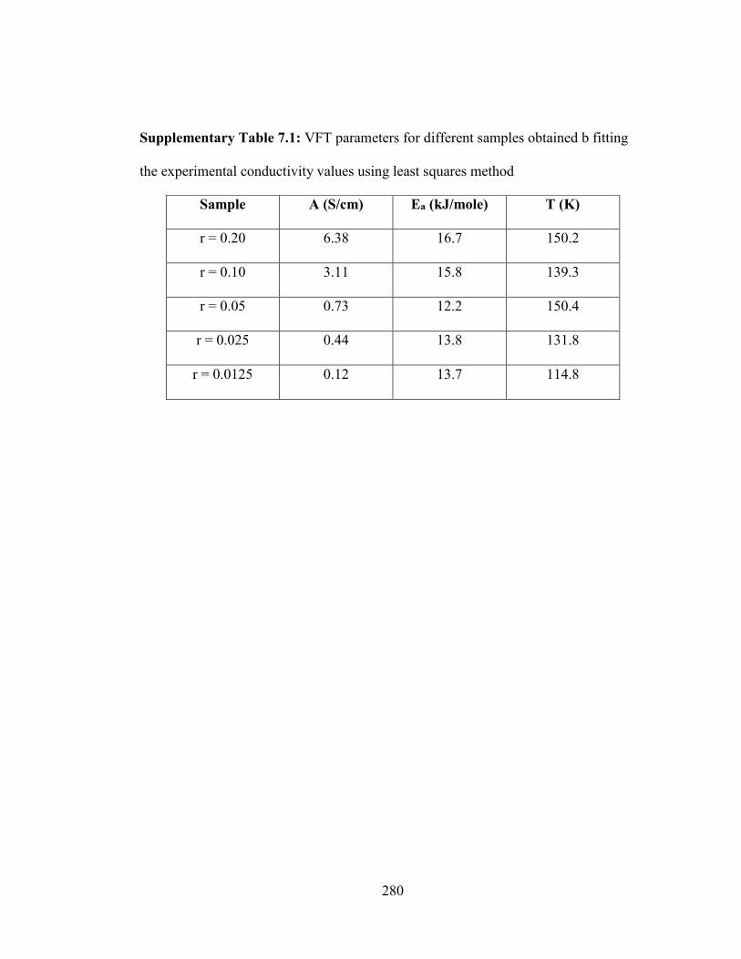
280
Supplementary Table 7.1: VFT parameters for different samples obtained b fitting
the experimental conductivity values using least squares method
Sample A (S/cm) Ea (kJ/mole) T (K)
r = 0.20 6.38 16.7 150.2
r = 0.10 3.11 15.8 139.3
r = 0.05 0.73 12.2 150.4
r = 0.025 0.44 13.8 131.8
r = 0.0125 0.12 13.7 114.8

281
Materials and Methods:
1. Synthesis of Self-Suspended Covalently grafted Hairy Nanoparticles:
Self-Suspended covalently grafted nanoparticles were prepared using a previously
described method. Briefly, these nanoparticles are prepared using a two-step process,
in which Polyethylene oxide was first functionalized with a silane group by reacting
the isocyanate end in 3-(triethoxysilyl) propyl isocyanate (Sigma-Aldrich) with the
amine end in amino-polyethylene oxide (MW ≈ 5000 Da, PDI ≈ 1.1, purchased from
Laysan Bio) in a stoichiometric ratio, creating a urethane bond in the process. The
prepared silane functionalized polymer was condensed onto silica nanoparticles with
diameter 25 ± 2 nm by reaction with the hydroxyl groups on the surface of the
particles ( TM-50, Sigma-Aldrich). Excess unreacted polymer chains were removed
by repeated centrifugation in a choloroform-hexane mixture. The inorganic content of
these hairy nanoparticles was analyzed using thermogravimetric analysis (TGA) on a
TGA Q1000 (TA Instruments). The TGA for different samples revealed inorganic
content of 51 % corresponding to grafting density of approximately 1.47 chains/nm2.
2. Characterization:
Glassy electrolytes were prepared by mixing the hairy nanoparticles with pre-
determined amount of LiTFSI salt (Sigma-Aldrich). The molecular structuring in the
glassy electrolytes were studied using attenuated total reflectance−Fourier transform
infrared spectroscopy (ATR-FTIR) on a Nicolet iS10 FTIR spectrometer (Thermo
Fisher Scientific) equipped with a deuterated triglycine sulfate (DTGS) detector and a
SMART iTR diamond ATR accessory. Melting transitions were then investigated

282
using differential scanning calorimetry on a DSC Q2000 (TA Instruments) at a scan
rate of 10oC/min. Morphology of the electrolytes at the electrode-electrolyte interface
was studied using Scanning Electron Microscope (Zeiss Gemini 500) at the Cornell
Centre for Materials Research (CCMR). Fourier transform infrared spectroscopy
(ATR FTIR) was performed on a Nicolet iS10 FTIR spectrometer (Thermo Fisher
Scientific) equipped with a deuterated triglycine sulfate (DTGS) detector and a
SMART iTR diamond ATR accessory.
3. Electrochemical Measurements
2030 coin-type cells were assembled in a glovebox (MBraun Labmaster) with Nickel
Cobalt Manganese Oxide (NCM) Cathode (2 mA/cm2) as the cathode and lithium foil
(Alfa Aesar) as the anode. The NCM cathode has 80%cative material (NCM 622),
10% binder (PTFE) and 10% carbon. The active material loading was ~11mg/cm2.
The glassy electrolyte was sandwiched between the two electrodes, after wetting the
cathode in a liquid electrolyte comprised of LiBOB (Oakwood Chemicals), LiTFSI
(Sigma-Aldrich) and LiPF6(Sigma-Aldrich) salts in an Ethylene Carbonate/Dimethyl
Carbonate (Sigma Aldrich) mixture.
Ionic transport in the bulk and at the interface in this system was studied using
conductivity and impedance measurements using a Novocontrol N40 broadband
spectrometer fitted with a Quarto temperature control system. The samples were
sandwiched between two gold-plated blocking electrodes. The cyclic voltametrry was
done in lithium versus stainless steel configuration using a CHI600 potentiostat. The

283
cycling characteristics of the cells were evaluated under galvanostatic conditions using
Neware CT-3008 battery testers.
3. Small-angle x-ray scattering measurements
X-ray scattering (SAXS) measurements were performed on the solvent-less
SiO2−PEGME nanoparticles at sector 12-ID-B of Argonne National Laboratory, using
a point collimated X-ray beam. The sample was smeared on a thermal cell, and the
measurements were performed at different temperatures, all above melting point of
PEG. The measured scattering intensity, I(q), depends on wave vector q and particle
volume fraction φ as
I (q, φ)= P(q) S(q,φ)
where P(q) and S(q, φ) represent the particle form factor and the interparticle structure
factor, respectively. Because in the limit of infinite dilution S (q, φ → 0) ≈ 1, the
particle form factor can thus be obtained from the scattering intensities of dilute
aqueous suspensions of particles. The structure factor can then be obtained by
normalizing the scattering intensity with the form factor.
4. Rheology Measurements: Rheology Measurements. Oscillatory shear rheology
measurements were performed at a temperature of 90°C using a Physica MCR 501
rheometer (Anton Paar at Cornell Energy Systems Institute (CESI)), outfitted with a
cone and plate geometry (10 mm diameter, 2° cone angle). To study the linear and
nonlinear viscoelastic properties of the materials, variable strain amplitude

284
measurements at a fixed angular frequency of ω = 10 rad/s as well as variable
frequency measurements at a fixed strain amplitude γ = 0.5%, were employed.

285
Chapter 8
Solid Polymer Interphases for Lithium Metal Batteries

286
8.1 Abstract
Metal based batteries that comprise of a reactive metal anode like lithium, sodium or
potassium are the future of energy storage devices because of their high volumetric
and gravimetric energy density. However, these batteries fail by three distinct modes –
chemical instability due to internal reactions, morphological instability due to uneven
electrodeposition and hydrodynamic instability due to convective flows at the vicinity
of electrode-electrolyte interface. Both liquid based, and solid-state electrolytes have
their individual advantages and disadvantages in mitigating these issues. Here, we
show that solid-polymer interphases based on crosslinked polymer networks can
essentially possess qualities from both of these worlds. We find that by tuning the
thermodynamic interactions between the polymer network and oligomer diluents, one
can control the bulk properties like ion transport and mass transfer rate. Thus, it is
possible to design solid-like electrolyte-phases where the electroconvective flows can
be inhibited, while maintaining high ionic conductivity. We further show that these
polymer networks act as excellent interfacial layer for lithium metal electrode to
inhibit dendrite growth and side reactions. On pairing with high voltage cathodes, the
lithium metal battery at ambient conditions exhibit over 250 cycles of stable operation
even at a high rate of 1mA/cm2.
8.2 Introduction
Powerful and long-lasting electrical energy storage devices are essential in modern
times. One highly sought-after pathway to such devices is evolving today’s ubiquitous
lithium-ion batteries to so-called ‘metal batteries’ that replace the graphitic anode with

287
an alkali metal block, including lithium, sodium and potassium.1,2 These batteries not
only augment the anodic capacity by factors as high as ten times, but also enables use
of higher-energy cathodes, including sulfur and oxygen.3–7 However, fundamental
issues involving morphological, chemical, and hydrodynamic instabilities at the alkali
metal anode must be addressed. First, rough electrodeposit structures grow on the
metallic anode to eventually short-circuit the cell, inducing early battery failure and
potential thermal runaway processes.8,9 Second, parasitic side-reactions between the
electrolyte and the expanded anode promote electrolyte loss, ultimately lowering the
cell efficiency over time.10–13 These effects are both exacerbated by the large volume
change experienced by alkali metal electrodes during cycles of charge and discharge
and by the tendency of associated interface strain to damage/destroy the passivating,
but fragile interfacial material phases formed spontaneously on the electrode. A third
mode of failure arises from unstable electro-convective flows in liquid electrolytes at
current densities above the diffusion limit. This latter process is a consequence of ion
depletion at the electrode interface and has been studied extensively in the context of
electroplating processes.14
Conventional wisdom holds that solid-state electrolytes composed of mechanically
strong and chemically inert materials may offer a unified strategy for mitigating all
three sources of instability. The successes and failings of such all solid-state alkali
metal batteries are beginning to emerge from fundamental9,15–17 and application-
focused studies.18,11,19,12 Among the most important challenges that have emerged
from such studies include: (i) the difficulty of finding materials that simultaneously
offer sufficient mechanical rigidity to slow the growth kinetics of non-planar metal

288
deposits and fast room-temperature bulk and interfacial ion transport — particularly
when the alkali metal electrode is used in tandem with high-capacity intercalating
cathodes such as LiCoO2 (LCO), LiNiMnCoO2 (NMC), and LiNiCoAlO2 (NCA); (ii)
the inability for many of the best electrolyte candidates to reversibly deform and flex
to accommodate volume change at the anode; and (iii) the complex, insulating
interphases formed by solid-state electrolytes in contact with the reactive alkali metal
electrode. Dense polyether-based networks with high crosslink densities have been
reported in multiple recent studies18,20,21 to be effective in overcoming some of these
challenges at low current densities. More recently, Wei, et al.22 reported that liquid
electrolytes that incorporate high molar mass polymers to form molecular
entanglements in the liquid and thereby impart viscoelasticity are effective in
stabilizing deposition of metals at intermediate current densities, particularly at
electrodes composed of softer alkali metals such as sodium.
We report on the physical and electrochemical characteristics of thin, cross-linked
polymer electrolyte interphases formed directly on the surface of Li metal anodes. We
find that the interactions and composition of such interfaces can be easily tuned in the
presence of a compatible liquid electrolyte host to create single-component, elastic
membranes on the surface of a lithium metal anode. It is further shown that intrinsic
chemical and physical features of the membrane design imparts high levels of
reversibility to electrochemical processes at the anode, including elimination of
hydrodynamic instability by indefinitely extending the diffusion limited ion migration
regime. Deployment of the cross-linked polymer membranes in electrochemical cells
composed of metallic Li anodes and commercial-grade Nickel Manganese Cobalt

289
Oxide (NMC) cathodes reveals that the membranes facilitate high-columbic efficiency
stable cell operations in cell configurations where the membranes function either as
artificial solid electrolyte interfaces or as single component solid-state electrolytes.
Direct visualization studies of Li electrodeposition reveal that the ability of the elastic
interfaces formed in contact with the Li anode to promote compact deposition is an
important source of the electrochemical stability and versatility of the materials.
8.3 Results and Discussion
Figure 8.1a shows a schematic of the synthesis scheme used to create the polymer
membranes used in the present study. It is a facile, single-step polymerization process
and does not involve incorporation of any undesired solvent. Specifically,
poly(ethylene glycol) dimethacrylate (PEGDMA) of molecular weight 750 Da is
added to Bis(2-methoxyethyl) ether (diglyme) at varying volume fractions. In the
presence of a suitable free-radical initiator, such as methyl benzoylformate (MBF), the
DMA end groups form up to two linkages with other PEGDMA chains; rapidly cross-
linking the material and trapping the mobile diglyme component in the pores. The
ratio of lithium ions (Li+) to ethylene oxide (EO) was maintained at 0.10 via addition
of a simple, low-cost lithium salt, Lithium Nitrate (LiNO3). Cross-linking was
achieved in the present work through photo polymerization via exposure of the
interfaces to ultraviolet (UV) light (320 nm) irradiation. The result of the photo-
polymerization is a soft membrane, tightly bound to the underlying substrate. The
degree of softness is dependent on the diglyme content in the overall mixture because
only PEGDMA participates in cross-linking. Figure 8.1b shows a membrane with 40%
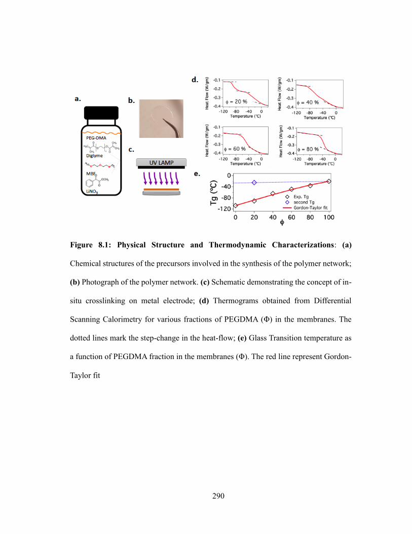
290
Figure 8.1: Physical Structure and Thermodynamic Characterizations: (a)
Chemical structures of the precursors involved in the synthesis of the polymer network;
(b) Photograph of the polymer network. (c) Schematic demonstrating the concept of in-
situ crosslinking on metal electrode; (d) Thermograms obtained from Differential
Scanning Calorimetry for various fractions of PEGDMA (Φ) in the membranes. The
dotted lines mark the step-change in the heat-flow; (e) Glass Transition temperature as
a function of PEGDMA fraction in the membranes (Φ). The red line represent Gordon-
Taylor fit

291
PEGDMA content (I) that is transparent and homogenous, exhibiting no observable
aggregates or signs of crystallite formation. Further it can be seen in Supplementary
Figure 8.1 that it has a rubbery texture and is able to recover fully even after
macroscopic deformation. The curing process can be carried out on lithium or other
substrates of lower surface energy (represented in the schematic of Figure 8.1c). This
versatility is important as it allows the materials to be studied in detail either in the
form of in-tact solid electrolyte interphases on Li, as single-component solid-state
electrolytes, or as free-standing films.
Evolution of the chemical bonding chemistry in the membranes with varying
PEGDMA content in the precursor solution (I) was studied via Fourier transform
infrared spectroscopy (FTIR). The results illustrated in Supplementary Figure 8.2
show that the C=O bond at ~1,700 cm-1 associated with PEGDMA increases in
intensity and shifts to lower wave number with increasing PEGDMA content. This
shift is an indication of a reduction in the effective moment of inertia of the absorbers,
which correlates with a reduction in the spacing between network points in the cross-
linked material. Thus, increasing PEGDMA content results in higher crosslink density,
which leads to membranes that are macroscopically more elastic and mechanically
stronger.
Supplementary Figure 8.3 illustrates how such an in-situ cross-linked membrane might
be used as artificial solid-electrolyte interphases (ASEI) to inhibit physical and
chemical instabilities at an alkali metal electrode. Before assessing the electrochemical
consequences of this ASEI design, we first consider the fundamental physical features
of the materials and on that basis elucidate their versatility. Results from differential

292
scanning calorimetry (DSC) of the of pure diglyme-LiNO3 (I = 0 %) as well as pure
PEGDMA membrane-LiNO3 (I = 100 %) are shown in in Supplementary Figure 8.4,
while the DSC thermograms for intermediate I’s are provided in Figure 8.1d. In the
specific ranges of temperatures displayed in these figures, a second-order phase
transition is observed that is associated with the glass transition of the polymer
membranes. This transition reflects the phase change from melt to a glassy state due to
kinetic entrapment of the molecules due to free volume reduction. The glass transition
temperature (Tg) observed for I = 0, corresponding to pure diglyme-LiNO3 and I =
100 % (pure PEGDMA - LiNO3) are -107.58qC and -20.37qC, respectively as shown
in Supplementary Figure 8.4. Polymer blends with It is known that compatible
polymeric mixtures show distinct Tg’s intermediate of the respective materials, while
that of a fully-mixed blend result in a single Tg that is dependent on the molecular
dispersion and relative strength of intermolecular forces in the materials. The
membrane with 20% PEGDMA content shows two distinct Tg values of -91.01qC and
-25qC (see Figure 8.1d), which can be asserted to two-phases that are rich in diglyme
and PEGDMA, respectively. At this particular I, the membrane exists in two separate
phases, which implies that the PEGDMA in the original mixture is not adequate to
form a fully-connected network after crosslinking. This means that only a small
fraction of the added diglyme interacts with the crosslinked phase, while the rest exists
as a second phase that is essentially a free liquid.
At I =40%, the glass transition event occurs over a visibly broadened range of
temperature, indicating that the PEGDMA network in the membrane is at that point at

293
the limits where it exists as a one single component. At this composition, the separate
Tg values begin to merge, indicating a chemically homogenous material such that the
PEG chains are permeated evenly throughout the membrane and it inherits the
mechanical toughness of a fully crosslinked network, while maintaining conductivity
close to that of a neat (liquid) electrolyte. As the PEGDMA composition is increased
further, the Tg values fully merge to a sharp transition (shown at I = 60% and above),
indicating the formation of a single phase percolated network. At this point, the cross-
linked networks exhibits characteristics of so-called solid-state electrolytes:
mechanically resilient yet limited by low ionic conductivity.
Figure 8.1e compares Tg values for the synthesized material at all PEGDMA content.
The measured Tg values were fitted to the classical Gordon-Taylor relation: Tg =
(w1Tg1 + Kow2Tg2) / (w1 + Kow2), where w1 and w2 are weight fractions of
diglyme-LiNO3 and PEGDMA-LiNO3, while Tg1 and Tg2 are the glass transition
temperature of the same. Ko here is 0.35 that is obtained from the least square fitting of
the experimental values, which is indicative of the relative change in heat capacities
compared to the pure components. The Gordon-Taylor relationships holds for non-
interacting (F = 0) polymer mixtures. It was noted that the second glass transition
temperature at I = 20% that doesn’t follow the Gordon-Taylor relation was recorded
to be close to the value at I = 100%. Thus, it can be concluded that as the PEGDMA
content in the overall mixture increases, the first phase (rich in PEG network) continue
to grow and essentially engulf the diglyme molecules to form a dense and swollen
percolated network of polymer chains.

294
Figure 8.2: Structure dependent Ion Transport Properties: (a) Normalized ac
Conductivity as a function of frequency. Measured values are shown as markers, while lines
are the data fitted to Cramer’s Equation. (b) Results from frequency dependent conductivity
measurements. Left axis shows the ion transport relaxation time, and right axis describes ratio
of back hop-rate over forward hop-rate obtained from the power-law model. (c) Conductivity
as a function of PEGDMA content at fixed temperature. (d) Activation energy of ion transport
as a function of PEGDMA content obtained by VFT model.

295
Frequency dependent conductivity can reveal important information regarding the ion
transport mechanisms as well as structural arrangements. Figure 8.2a reports the
normalized real component of a.c. conductivity as a function of frequency for different
PEGDMA content obtained using Dielectric Spectroscopy at 30qC. The range of
frequency values reported in Figure 8.2a only captures the high-to-mid values below
which polarization effects at electrode-electrolyte interface start to dominate. It is seen
that at lower frequencies the conductivity is independent of frequency denoting the
bulk or d.c. conductivity (Vo). In the high frequency region, the conductivity values
progressively rise beyond a critical frequency of Zc due to correlated ionic motions
and depend on the host media microstructure as well as temperature. Such behavior
has also observed universally in several glassy and solid polymer electrolytes reported
in the literature. The solid line fits in Figure 8.2a represent the jump-relaxation model
proposed by Jonscher23 for thermally activated processes that was be mathematically
reproduced by Cramer et al.24 as a power-law expression: σ = σo [1 + (τω)p]. Here τ
is the timescale for dielectric relaxation that depends upon the coulombic interactions
between the polymer chains and mobile ions. The power law exponent p denotes the
ratio between the forward hop to backward hop relaxation time. The variation of τ and
p with different PEGDMA content (I) is represented in Figure 8.2b. It is seen that the
ion hopping relaxation time (τ) increases rapidly beyond I = 40%. This can be
attributed to a transition of conduction mechanism from bulk motion of oligomers to
ion hopping processes along the EO links in the percolated network. The evidence of
this is the transition from a mixed diglyme-network to a single-phase solid electrolyte
observed from the glass transition behavior at and beyond I = 40%. Furthermore, the

296
p-value is seen to changes from >1 to less than unity at the same fraction. Previously
in the literature, solid polymer electrolytes based on PEO have been reported to
exhibit p < 1 due to the cationic nature of the ion transport where Li+ ions hop through
coordination with EO molecules, however, at elevated temperatures as well as for
liquid electrolytes p is seen be higher than 1. This argument similarly validates our
proposed idea that all diglyme molecules are ‘tightly’ bound by the percolated
network beyond I = 40%.
Supplementary Figure 8.5 reports the d.c. conductivity obtained from the plateau
region of the frequency dependent conductivity as a function of inverse temperature.
The continuous lines here represent the Vogel–Fulcher–Tammann (VFT) model given
by, σo = Α exp(−Ea/R(T−To)), provides relationship between the ion transport rate
and temperature. Here, A is a pre-factor related to the overall number of charge carrier,
Ea is the activation energy and To denote the characteristic temperature below which
the ion transport ceases to take place. The excellent fitting of the VFT model confirm
the absence of any temperature induced chemical or morphological changes in the
measured range. The comparison of the conductivity values at 30qC is plotted as a
function of I in Figure 8.2c. It is seen that the conductivity from I = 0 to 40% only
decreases by an order of magnitude and thereafter, as PEGDMA becomes the majority
in mixture, the conductivity of the membrane quickly drops off by several orders of
magnitude. Operation of cells created using the membrane of above 40% PEGDMA
content as an electrolyte composite content would require increased operating
temperatures similar to solid polymer electrolytes previously reported in the
literature.20,25,26 Figure 8.2d reports the activation energy obtained from the VFT
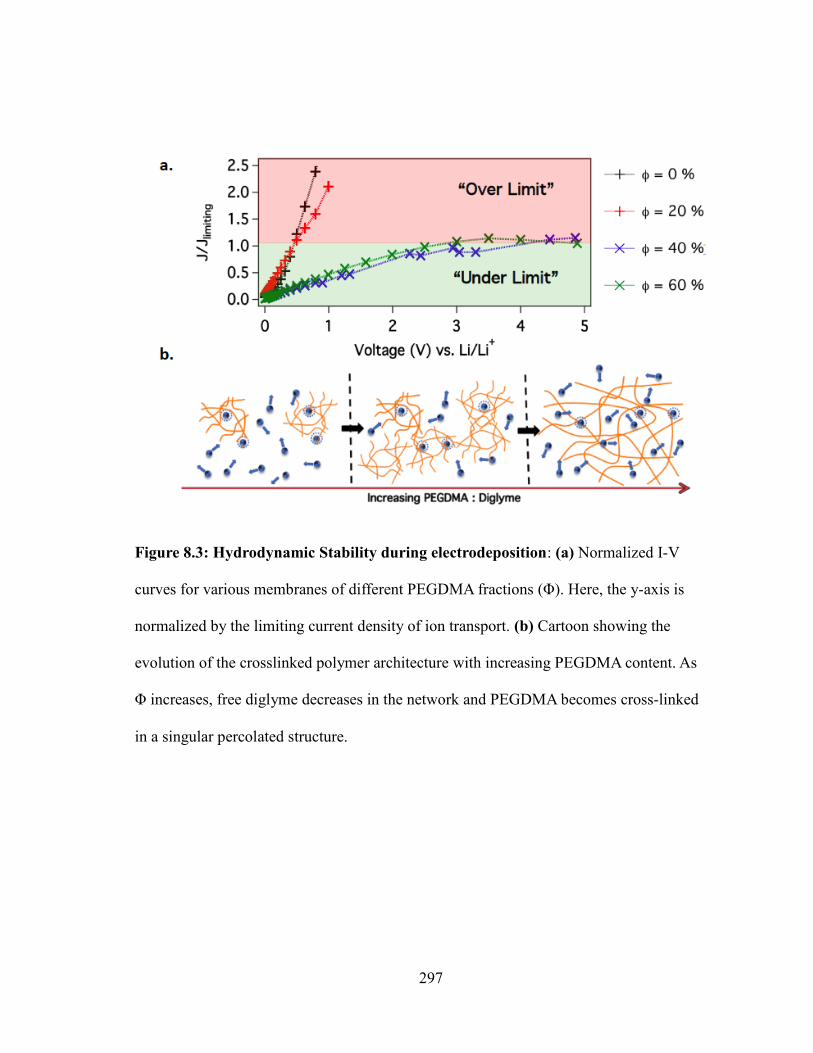
297
Figure 8.3: Hydrodynamic Stability during electrodeposition: (a) Normalized I-V
curves for various membranes of different PEGDMA fractions (Φ). Here, the y-axis is
normalized by the limiting current density of ion transport. (b) Cartoon showing the
evolution of the crosslinked polymer architecture with increasing PEGDMA content. As
Φ increases, free diglyme decreases in the network and PEGDMA becomes cross-linked
in a singular percolated structure.

298
fittings. It is evident that the activation energy for ion hopping increases sharply
beyond I = 40%. This implies that ion transport through the membrane occurs at more
easily at lower PEGDMA content. Thus, the molecular interactions between the
oligomers and polymer network ultimately regulates the bulk-scale ion transport
processes.
In absence of forced convections, electrodeposition is a diffusion-limited process such
that ion transport rate at every potential differences should be a function of ionic
conductivity. However, at intermediate voltage differences, the ion transport rate
should reach a maximum value, known as the limited current density, which can be
calculated as Jlim = zFDc/G, where z is the charge, F is Faraday constant, c is bulk
concentration, D is ion diffusivity and G is the diffusion layer thickness. At even higher
voltages, the ion migration rate cannot exceed the diffusion rate, thus the
electroneutrality fails to be maintained at the electrode-electrolyte interfaces resulting
in creation of a space charge region. It has been experimentally observed as well as
predicted from Nernst-Planck Theory that a large electric field near the electrodes
generates a convective flow field driving the ions across the space charge region,
thereby exceeding the limiting current to a ‘over-limiting’ value. Since, the current
flow in these conditions occur not by the electroconvective flows rather than ion
diffusion, it results in several unwanted events like electrolyte degradation and
rampant dendritic growth on the electrodes. It can be safely argued that these
instabilities are absent in all solid-state electrolytes but can occur in Newtonian fluids.
Thus, such experiments are important with context of the present work to classify the
crosslinked polymer networks.

299
Supplementary Figure 8.6 reports current density as a function of voltage for our
membranes of different PEGDMA content. The measurements were performed in
symmetric (Li||Li) two-electrode cells. The voltage was scanned in stair-case
progression from 0V to 5V vs. Li/Li+, and the resultant steady-state current was
recorded. In I = 0, 20% PEGDMA content electrolytes, quick divergence of current
can be observed, without any obvious plateau region in the current density as opposed
to the higher PEGDMA contents. Figure 8.3a shows the data reported in
Supplementary Figure 8.6 after normalization by the limiting current of ion transport.
Jlim for I = 0, 20% were calculated from the theoretical expression using G as the inter-
electrode spacing while, Jlim for the I < 40% was calculated from the observed plateau
region. The data reports that for PEGDMA content I < 40% quickly rises to regions of
transport instability, over the limiting current. Past the diffusion-limited current,
electroconvection dominates ion transport. However, for I ≥ 40%, the current through
the electrochemical systems is limited at the critical current, signaling stable ion
transport. As the PEGDMA polymer network architecture exist as a single percolating
solid at higher (40-100%) PEGDMA content, electroconvection is negated.
A cartoon summarizing the observed effect is represented in Figure 8.3b. The
architecture of the crosslinked PEGDMA chain network in the solid polymer
interphase membrane is shown. With diglyme in excess, the physically wet membrane
exhibits many free diglyme chains, and some interacting in a thinly populated
PEGDMA supramolecules. As the PEGDMA content was incrementally increased, the
percolated network exhibited more diglyme chains interactions. It is interesting that
oligomer-polymer interactions not only regulate the thermodynamic behavior, but it is

300
Figure 8.4: Morphological Stability and Electrochemical Performances: (a)
Snapshots from direct-visualization. The first row shows results lithium coated with
the synthesized solid polymer interphase; the second row shows results with the
uncoated lithium electrode. In both cases the electrolyte of 1 M LiPF6 in EC/DMC
was used and current density was 4mA/cm2. (b) Average height of dendrite as a
function of time. (c), (d) Voltage profiles for lithium vs. NCM batteries where the
lithium anode is coated with the solid polymer interphase for C-rates of C/5 and C/2
respectively. The electrolyte used is 0.6M LiTFSI, 0.4M LiBOB 0.05 LiPF6 in
EC/DMC.

301
also manifested in ion transport behavior and macro-scale hydrodynamics. Based on
this, we can select PEGDMA content I = 40%, as the optimum candidate for
designing our Solid Polymer Interphase (SPI) that simultaneously exhibit liquid and
solid-like characteristics.
To characterize macroscopic morphological evolution during electrodeposition, an in-
house built visualization setup was utilized. The set-up contained dual-lithium metal
rods as the electrodes coated with the SPI and liquid electrolyte of 1M EC:DMC LiPF6
in the interelectrode space, filling the center of the tube. Electrodeposition was
visually recorded under an optical microscope using a current density of 4 mA cm-2.
Electrodeposit morphology for both coated and uncoated electrodes was observed at
regular intervals up to 1 hour, as shown in Figure 8.4a. For the control electrolyte, the
electrodeposit morphology is “mossy” and rough as compared to the case with the
solid polymer interphase. This effect is the result of three mechanisms. The physical
barrier provided by the SPI provides the electrolyte with the mechanical modulus to
resist uneven deposition. Further, the negation of electroconvection due to the
permeating polymer network encourages stable ion transport towards the electrode
surface. Lastly, at the electrode surface, the presence of the polymer composites
prevents continuous side reactions with the carbonate electrolyte. Quantitative analysis
of electrodeposit morphology was also reported. This was done by plotting the height
of deposit at various times, shown in Figure 8.4b. In a linear regression of the data, the
growth rate of the pristine lithium deposits with the control electrolyte was found to be
~90 nm s-1, while that with the SPI was found to be ~20 nm s-1. Supplementary Figure
8.7 reports cell coulombic efficiency (CE) as a function of cycle number. Results were

302
obtained using an antisymmetric coin cell, with pristine Li electrode and stainless-steel
counter electrode with and without the SPI coating. In the control case, the cell cycles
stably at above 80% CE for around 30 cycles, before the CE drops and the cell fails. In
contrast, the coin cells fabricated with the SPI coating exhibited >80% CE for at least
100 cycles. It is clear that the SPI can promote long term electrodeposition stability.
Finally, we paired the SPI coated lithium metal anode with high voltage cathode of
Nickel Manganese Cobalt Oxide (NMC). The electrolyte used is 0.6M LiTFSI, 0.4M
LiBOB 0.05 LiPF6 in EC/DMC (1/1 by wt.), which has been reported to be stable in
high potential operation. Figure 8.4c, 8.4d report the voltage profiles at a rate of C/5
and C/2, respectively. The capacity and coulombic efficiencies as a function of cycle
numbers are reported in Supplementary Figure 8.8a, 8.8b. Here, where 1C corresponds
to a current density of 2 mA cm-2. It can be seen in both the C-rates, that the initial
capacity is ~100 mAh gm-1 that eventually increases to ~185 mAh gm-1 and ~155 mAh
gm-1 for C/5 and C/2 respectively. However, the coulombic efficiency is seen to be
remain close to 100% throughout the battery operation, this indicates that initial rise in
the capacity is due to the increasing interfacial conductivity as the liquid electrolyte
wets the SPI. It can be seen at both C-rates that the discharge capacity retention even
after 250 cycles of operation is more than 90%.
In conclusion, we designed crosslinked solid polymer networks based on PEG
chemistry for using as a solid polymer interphase on a lithium metal electrode. We
systematically varied diglyme diluent in the polymer network to understand how
thermodynamic interactions affect bulk properties. It was observed at high diglyme
content, it partly interacts with the sporadic networks and the majority remains

303
unbounded. Specifically, at 20% PEGDMA two distinct Tg’s were observed, followed
by a fully interacting network at 40% and beyond. Thus at 40% PEGDMA content, the
diglymes was loosely held by the network resulting in high ionic conductivity in
contrast to higher content values. Also, at this critical content of PEGDMA, the solid
electrolyte membrane did not manifest any electroconvective flows, thus possessing
qualities of both solid and liquid electrolytes. Finally, we utilized the optimum
crosslinked network as a solid interphase on lithium metal battery to show stable
battery cycling due to inhibition of dendritic growth and electrode-electrolyte side
reactions.
8.4 Methods
8.4.1 Fabrication of crosslinked polymer network and coated lithium
Poly(ethylene glycol) Dimethacrylate (Mn = 750), Diglyme and Lithium Nitrate were
purchased from Sigma Aldrich. All chemicals were thoroughly dried before usage.
The PEGDMA and diglyme were mixed in different ratios as required, however the
LiNO3 content was maintained at Li:EO = 0.1 for all the samples. The mixture was
thoroughly mixed to obtain a uniform solution. After addition of 4 wt.% of a
photoinitiator methyl benzoylformate (MBF), the solution was casted on a desired
substrate and exposed to UV light (VMR UVAC 115 V ∼60 Hz 254/365 nm) for 20
minutes. After the reaction, the membranes were utilized as is for characterizations.
The solid polymer interphase was formed using the same procedure, however the
reaction was carried out on a flat piece of lithium metal anode in an Argon-filled
glove-box.

304
8.4.2 Material Characterization
The molecular structuring in the glassy electrolytes were studied using attenuated total
reflectance−Fourier transform infrared spectroscopy (ATR-FTIR) on a Nicolet iS10
FTIR spectrometer (Thermo Fisher Scientific) equipped with a deuterated triglycine
sulfate (DTGS) detector and a SMART iTR diamond ATR accessory. Melting
transitions were then investigated using differential scanning calorimetry on a DSC
Q2000 (TA Instruments) at a scan rate of 10oC/min.
8.4.3 Electrochemical Characterization
Ionic transport in the bulk and at the interface in this system was studied using
conductivity and impedance measurements using a Novocontrol N40 broadband
spectrometer fitted with a Quarto temperature control system. The samples were
sandwiched between two gold-plated blocking electrodes. The I-V analysis were done
using staircase voltammetry where each voltage steps comprise of 20 seconds using
Maccor battery testers.
2030 coin-type cells were assembled in a glovebox (MBraun Labmaster) with Nickel
Cobalt Manganese Oxide (NCM) Cathode (2 mA/cm2) as the cathode and lithium foil
(Alfa Aesar) as the anode. The solid-polymer coated lithium was paired with the NCM
cathode, and the in a liquid electrolyte comprised of LiBOB (Oakwood Chemicals),
LiTFSI (Sigma-Aldrich) and LiPF6 (Sigma-Aldrich) salts in an Ethylene
Carbonate/Dimethyl Carbonate (Sigma Aldrich) mixture.

305
The coulombic efficiency tests were performed in a cell configuration of lithium
anode with or without the solid polymer coating paired against a stainless steel counter
electrode. The electrolyte utilized was 1M EC:DMC LiPF6. In this measurement a
fixed amount of lithium was plated onto the stainless steel electrode and stripped back,
such that the ratio of stripped and plated lithium determined the coulombic efficiency
for each cycle.
The direct visualization experiment was done using two lithium rod-type electrodes in
a tube-like visualization cell.27

306
REFERENCES
1. Wei, S., Choudhury, S., Tu, Z., Zhang, K. & Archer, L. A. Electrochemical
Interphases for High-Energy Storage Using Reactive Metal Anodes. Acc. Chem.
Res. 51, 80–88 (2018).
2. Cheng, X. et al. A Review of Solid Electrolyte Interphases on Lithium Metal
Anode. Adv. Sci. 3, 1–20 (2016).
3. Lin, D., Liu, Y. & Cui, Y. Reviving the lithium metal anode for high-energy
batteries. Nat. Nanotechnol. 12, 194–206 (2017).
4. Cheng, X.-B., Zhang, R., Zhao, C.-Z. & Zhang, Q. Toward Safe Lithium Metal
Anode in Rechargeable Batteries: A Review. Chem. Rev. 117, 10403–10473
(2017).
5. Armand, M. & Tarascon, J.-M. Building better batteries. Nature 451, 652–7
(2008).
6. Ma, L., Hendrickson, K. E., Wei, S. & Archer, L. A. Nanomaterials: Science
and applications in the lithium–sulfur battery. Nano Today 10, 315–338 (2015).
7. Aurbach, D., McCloskey, B. D., Nazar, L. F. & Bruce, P. G. Advances in
understanding mechanisms underpinning lithium–air batteries. Nat. Energy 1,
16128 (2016).
8. Choudhury, S. et al. Confining electrodeposition of metals in structured
electrolytes. Proc. Natl. Acad. Sci. (2018).
9. Bai, P., Li, J., Brushett, F. R. & Bazant, M. Z. Transition of lithium growth
mechanisms in liquid electrolytes. Energy Environ. Sci. 9, 3221–3229 (2016).

307
10. Zhang, S. S. A review on electrolyte additives for lithium-ion batteries. J.
Power Sources 162, 1379–1394 (2006).
11. Suo, L. et al. Fluorine-donating electrolytes enable highly reversible 5-V-class
Li metal batteries. Proc. Natl. Acad. Sci. (2018).
12. Choudhury, S. & Archer, L. A. Lithium Fluoride Additives for Stable Cycling
of Lithium Batteries at High Current Densities. Adv. Electron. Mater. 1–6
(2015). doi:10.1002/aelm.201500246
13. Lu, Y., Tu, Z. & Archer, L. A. Stable lithium electrodeposition in liquid and
nanoporous solid electrolytes. Nat. Mater. 13, 961–969 (2014).
14. Tikekar, M. D., Choudhury, S., Tu, Z. & Archer, L. A. Design principles for
electrolytes and interfaces for stable lithium-metal batteries. Nat. Energy 1,
16114 (2016).
15. Tikekar, M. D., Archer, L. A. & Koch, D. L. Stabilizing electrodeposition in
elastic solid electrolytes containing immobilized anions. Sci. Adv. 2, e1600320
(2016).
16. Liu, W., Lin, D., Pei, A. & Cui, Y. Stabilizing Lithium Metal Anodes by
Uniform Li-Ion Flux Distribution in Nanochannel Confinement. J. Am. Chem.
Soc. 138, 15443–15450 (2016).
17. Zheng, G. et al. Interconnected hollow carbon nanospheres for stable lithium
metal anodes. Nat. Nanotechnol. 9, 618–623 (2014).
18. Choudhury, S., Mangal, R., Agrawal, A. & Archer, L. A. A highly reversible
room-temperature lithium metal battery based on crosslinked hairy
nanoparticles. Nat. Commun. 6, 10101 (2015).

308
19. Kozen, A. C. et al. Next-Generation Lithium Metal Anode Engineering via
Atomic Layer Deposition. ACS Nano 9, 5884–5892 (2015).
20. Khurana, R., Schaefer, J. L., Archer, L. A. & Coates, G. W. Suppression of
lithium dendrite growth using cross-linked polyethylene/poly(ethylene oxide)
electrolytes: a new approach for practical lithium-metal polymer batteries. J.
Am. Chem. Soc. 136, 7395–7402 (2014).
21. Bouchet, R. et al. Single-ion BAB triblock copolymers as efficient electrolytes
for lithium-metal batteries. Nat. Mater. 12, 452–457 (2013).
22. Wei, S. et al. Stabilizing electrochemical interfaces in viscoelastic liquid
electrolytes. Sci. Adv. 4, (2018).
23. Jonscher, A. K. The ‘universal’ dielectric response. Nature 267, 673–679
(1977).
24. Funke, K. & Cramer, C. Conductivity spectroscopy. Curr. Opin. Solid State
Mater. Sci. 2, 483–490 (1997).
25. Gurevitch, I. et al. Nanocomposites of Titanium Dioxide and Polystyrene-
Poly(ethylene oxide) Block Copolymer as Solid-State Electrolytes for Lithium
Metal Batteries. J. Electrochem. Soc. 160, A1611–A1617 (2013).
26. Stone, G. M. et al. Resolution of the Modulus versus Adhesion Dilemma in
Solid Polymer Electrolytes for Rechargeable Lithium Metal Batteries. J.
Electrochem. Soc. 159, A222–A227 (2012).
27. Choudhury, S. et al. Electroless Formation of Hybrid Lithium Anodes for Fast
Interfacial Ion Transport. Angew. Chemie Int. Ed. 56, 13070–13077 (2017).

309
APPENDIX
Supplementary Information for Chapter 7
Supplementary Figure 8.1: Photograph of the flexible crosslinked membrane.

310
Supplementary Figure 8.2: FTIR analysis of the crosslinked membrane at various
PEGDMA content that shows C=O bond at (1,700 cm-1) shifting to lower intensity
values as the volume percent PEGDMA is increased in solution.

311
Supplementary Figure 8.3: Schematic demonstrating the concept of stabilization
using a solid polymer interphase.

312
Supplementary Figure 8.4: Thermograms obtained from Differential Scanning
Calorimetry for pure diglyme (Φ = 0 %) and pure PEGDMA network (Φ = 100 %).
The dotted lines mark the step-change in the heat-flow

313
Supplementary Figure 8.5: d.c. conductivity as a function of inverse absolute
temperature. Measured values are shown as markers, and the data is fitted to Vogel
Tamman Fulcher function.

314
Supplementary Figure 8.6: Current as a function of voltage. Divergence in current
was seen for Φ=0% and Φ=20%, signaling the presence of electroconvection. For
Φ=40% and beyond, the current reached a limiting value at higher voltages

315
Supplementary Figure 8.7: Coulombic efficiency measurement in Li || stainless steel
coin cell with and without the solid polymer interphase at a current density of 1 mA
cm-2 and capacity of 1 mAh cm-2, using the 1 M LiPF6 in EC/DMC electrolyte.

316
Supplementary Figure 8.8: Cycling performances for Li||NMC cell operated at a C-
rate of (a) C/5 and (b) C/2. Here the lithium metal electrode was coated with the solid
polymer interphase that comprises of the polymer network and diglyme, with
PEGDMA content of 40%. The thickness of the polymer coating was ~100Pm. The
capacity of cathode is 2mAh/cm2 and the electrolyte used here is 0.6M LiTFSI, 0.4M
LiBOB, 0.05 LiPF6 in EC/DMC (1:1 by wt.)
a
b

317
Supplementary Figure 8.9: Cycling performances for Li||NMC cell operated at a C-
rate of C/5. Here the electrolyte utilized was an all-solid state polymer electrolyte that
comprises of the polymer network and diglyme, with PEGDMA content of 40% and
with the salt LiNO3 (Li:EO = 0.10) and 0.4M LiBOB as additive. The thickness of the
solid polymer electrolyte was ~400Pm. The capacity of cathode is 2mAh/cm2. The
cathode surface was wetted by liquid electrolyte of diglyme-LiNO3 (Li:EO = 0.1) and
0.4M LiBOB.

318
Chapter 9
Stabilizing Polymer Electrolytes in High-Voltage Lithium Batteries
319
9.1 Abstract
More than forty years after the first report of a rechargeable lithium battery,
electrochemical cells that utilize metallic lithium anodes are again under active study
for their potential to provide more energy dense storage in batteries. Electrolytes based
on small-molecule ethers and their polymeric counterparts are known to form stable
interfaces with alkali metal electrodes and for this reason are among the most
promising choices for rechargeable lithium batteries. Uncontrolled anionic
polymerization of the electrolyte at the low anode potentials and oxidative degradation
at the working potentials of the most interesting cathode chemistries have led to a
quite concession in the field that solid-state or flexible batteries based on polymer
electrolytes can only be achieved in cells based on low- or moderate-voltage cathodes.
Here we show that cationic chain transfer agents in an ether electrolyte provide a
fundamental strategy for limiting polymer growth at the anode, enabling long term (at
least 2000) cycles of high-efficiency operation of asymmetric lithium cells. Building
on these ideas, we also report that cathode electrolyte interphases composed of anionic
polymers and the superstructures they form spontaneously at high electrode potentials
provide as fundamental a strategy for extending the high voltage stability of ether-
based electrolytes to potentials well above conventionally accepted limits. Through
computational chemistry, we discuss the mechanistic processes responsible for the
extended high voltage stability and on this basis report Li||NMC cells based on a
simple diglyme electrolyte that offer unprecedented stability in extended galvanostatic
cycling studies.

320
9.2 Introduction
Small-molecule linear and cyclic ethers/glymes and their carbonate esters formed by
reaction with carbon dioxide have emerged as the most important family of
electrolytes for lithium batteries. These molecules are attractive for a variety of
reasons, including their low viscosity and ability to coordinate with lithium ions,
producing higher concentrations of mobile charge carriers than one would anticipate
from classical theory, based on their dielectric constants alone.1–6 Macromolecular
analogs, most notably polyethylene glycol dimethyl ether (PEGDME), have been
reported to offer additional beneficial effects, including orders of magnitude higher
mechanical modulus, low volatility and low flammability, making them attractive
candidates for solid-state or flexible lithium batteries in a variety of form factors.7–11
A substantial body of work focused on charge carrier transport mechanisms in
polyethers has shown that lithium ion mobility is coordinated with molecular motions
and that charge carrier transport occurs predominantly in the amorphous phase of the
materials where molecular mobility is highest.12–16 A less studied, but as important
trait of ethers is the ease with which they can be electropolymerized at the reducing
potentials at the lithium battery anode, as well as at the oxidizing potentials of the
cathode. Almost nothing is known about how these processes can be regulated to
produce self-limiting interphases and how fast ion transport at such interphases might
be used to stabilize deposition at the Li anode.
Reduction of small-molecule ethers and carbonate esters at a lithium battery anode
produces less mobile polymeric species by ring-opening and/or anionic

321
chemistries.2,4,17–19 In favorable situations (e.g. at the graphitic carbon anode of state-
of-the art lithium ion batteries) the reactions are self-limiting and produce a thin
coating of a low-molar mass polymer-rich phase (interphase) at the electrode surface.
This so-called solid-electrolyte interface (SEI) limits molecular access to the electrode
surface and prevents continuous loss of electrolyte. The SEI is known to be crucial for
stable, long-term battery operation, but almost nothing is known about how the tools
of polymer chemistry can be used to harness it to achieve a similar electrochemical
function at more unstable (chemical and morphological) alkali metal anodes. In cells
that use lithium metal as anode, spontaneously formed interphases are in fact rarely
self-limiting. Numerous studies have begun to appear that center on materials
synthesis strategies for creation of specially designed self-limiting interfaces on such
anodes using sacrificial, easily reduced species added to an electrolyte,20–23 or
application of ion permeable coatings formed ex-situ.24–26
At the intercalating composite cathodes (e.g. NMC, LMO, LCO) of greatest
contemporary interest for lithium cells, electrolyte-electrode interfaces are not
restricted to planes. Designing self-limiting interphases able to reduce/prevent
electrolyte oxidation is therefore far more complex. Because ethers are particularly
vulnerable to oxidative attack, a concession is the field is that ether- and polyether-
based electrolytes cannot be used in practical electrochemical cells that employ high-
voltage cathodes.27 As a consequence, solid-state ceramic electrolytes have emerged in
recent years as the most promising candidates for all solid-state lithium batteries.

322
Here, we consider the chemical processes responsible for uncontrolled interphase
polymer chain growth at the anode and oxidative degradation of ethers at the cathode
of a lithium cell and on that basis show that electrolytes based on ethers can be
designed to overcome conventional limitations. We show in particular that inhibition
of anionic polymerization of electrolytes based on chain transfer agents (CTAs) offer
unusually high levels of interphase stability at a lithium metal anode. We further
report that anionic species able to limit transport of polymer intermediates at the
cathode are an integral component in designing self-limiting cathode electrolyte
interfaces (CEIs) able to stabilize glymes at highly oxidizing electrode potentials.
Taken together with recent work showing that polyethers in a variety of cross-linked
configurations are able to inhibit rough, dendritic electrodeposition at a lithium metal
anode during battery recharge, the results reported herein provide a path towards safe,
cost-effective solid state and flexible batteries based on polymer electrolytes.7,28,29
The electrolyte used in the study is comprised of Bis(2-methoxyethyl) ether (diglyme)
and Lithium Nitrate (LiNO3) salt. The choice of LiNO3 is based on the fact that it is
cheaper compared to other salts and it is known to form a stable interfacial layer on
the anode.30 Diglyme is chosen as the simplest oligo-ether that offers the combination
of a high boiling point (162qC) and appreciable ion transport rate at ambient
temperature to be of interest as an electrolyte for the lithium metal battery. The
chemical structure of the electrolyte, including the ease with which the molecule can
be electropolymerized at the cathode or anode of an electrochemical cell is shared with
all ether-based liquid and solid polymer electrolytes, which means that the interfacial
polymerization, oxidative breakdown, and transport characteristics of diglyme at

323
electrodes are to a reasonable approximation representative of a much broader class of
polymer electrolyte candidates. The LiNO3 concentration in diglyme is systematically
adjusted by varying the ratio, r, of Li+ cations to ether oxygen (EO) molecules in the
electrolyte.
9.3 Results and Discussions
Supplementary Figure 9.1a reports the effect of r on the temperature-dependent
electrolyte conductivity. The conductivity values at room temperature are seen exceed
1mS/cm for all materials used in the study, but there are appreciable variations at sub-
zero temperatures. It is clear from the results that diglyme-LiNO3 electrolytes with r =
0.1 exhibit the highest conductivity compared across the range of measurement
temperatures employed in the study. It is also notable that even at temperature of -
30qC, the conductivity of this electrolyte is >1mS/cm, which makes it suitable for low-
temperature battery operation without any compromise in power density. The
continuous lines in Supplementary Figure 9.1a shows that the Vogel–Fulcher–
Tammann (VFT) model, V = Α exp(−Ea/R(T−To)). Here, Ea is related to the free
volume required to move the ions and To is related to the glass transition temperature
of the polymer (typically found to be in order of Tg-50). Ea, obtained from this
analysis provides a measure of the facility with which ions move in an electrolyte
plotted and are reported as a function of r in Supplementary Figure 9.1b. Ea is seen to
increase monotonically with r, similar to the glass transition temperature (Tg), also
plotted in Supplementary Figure 9.1b. This result indicates that there are high levels of
molecular association between the diglyme and the salt and is consistent with the idea

324
that as the salt concentration is increased, diglyme molecules move in a more coupled
manner. On the basis of these results, we utilize an electrolyte with r = 0.1 for all
subsequent studies.
Glyme or ether based electrolytes are known to undergo anionic polymerization at the
surface of alkali metals, particularly at the highly reducing potentials at the anode. The
resultant polymer-rich interphases are desirable because they passivate the electrode
against parasitic chemical reactions with the electrolyte. Glymes are for this reason
among the most preferred electrolytes for electrochemical cells in which alkali metals
are to be used as anodes.1,19,30 Unfortunately, left unchecked, the polymers formed
may grow to such high molecular weights that Li+ transport to the electrode is
severely retarded. Alkali metals are thought to initiate polymerization by cleaving a
proton from the side-chain of a glyme molecule as shown in Figure 9.1a. The polymer
chain grows by an addition process wherein the active anionic reactive center collides
with another glyme molecule, extending the length of the chain. Because electrostatic
interactions between active centers prevent collisions between growing chains and
centers can be stabilized by Li ions in solution, the growth can in principle progress
indefinitely to produce extremely large, poorly conductive polymer chains or until all
available glyme molecules are integrated into the growing center. In either event, ion
mobility in the electrolyte bulk falls and interfacial resistance rises, producing
premature failure of the cell by voltage run-away.

325
Figure 9.1: Enabling stable electrodeposition of lithium metal: (a) Schematic showing the possible cleavage sites for diglyme and HFiP molecules such that the uncontrolled polymerization of diglyme is quenched by the CH(CF3)2
+ radical; (b) Voltage profile for the electroplating and stripping of lithium metal at the same current density. The different numbers represent cycle no.; (c) Scanning electron microscopy image of stainless steel substrate after lithium deposition for 6 hours at the current density of 1mA/cm2; (d) Coulombic efficiency measurements in a Li||stainless steel battery at a current density of 1mA/cm2 and capacity of 1mAh/cm2. The black circles represent the diglyme-LiNO3 electrolyte with the HFiP additive and red triangles are for neat electrolyte

326
We hypothesize that an electrolyte that addresses this fundamental, termination-free
characteristic of anionic addition polymerization could limit chain growth to produce
self-limited SEI on a metallic electrode. To test this idea, we employ the molecule
Tris(hexafluoro-iso-propyl)phosphate (HFiP) that is known to readily degenerate to
form multiple CH(CF3)2+ species per molecule 31,32. The large number of electron
withdrawing groups near the cationic fragments should enable rapid, and efficient
quenching of anionic polymerization of glyme molecules by the chain transfer
mechanism depicted in Figure 9.1a. As a proof of concept, we performed a simple
analysis wherein lithium metal was dipped in diglyme-LiNO3 electrolyte with and
without HFiP additive aged for a month. Supplementary Figure 9.2 shows the image
vial bottles, where it is seen that the electrolyte without the CTA turns yellow due to
uncontrolled polymerization of the diglyme molecules, while the lithium is blackened
due to surface reactions. In comparison, the HFiP additive stabilizes not only the
diglyme solution but also the lithium surface maintains its pristine form. Furthermore,
surface of lithium from both vial bottles were analyzed using X-ray Photoelectron
Spectroscopy (XPS) and reported in Supplementary Figure 9.3 & 9.4. The F-1s XPS
for the case with HFiP additive has a single peak at 688.9eV representing–CF3 bond,
which is further confirmed from the C-1s XPS from the peak at 293.3eV, while it is
absent in the C-1s for the lithium extracted from additive-free lithium.33 The absence
of a metal-fluoride binding energy peak is a confirmation that the –CF3 groups do not
decompose in the presence of the lithium metal electrode, ruling out an alternative
stabilizing mechanism reported in our previous work.22,23

327
The effectiveness of the approach to create self-limited interphases on a Li anode was
evaluated in an asymmetric electrochemical cell comprised of lithium metal and
stainless-steel electrodes. By comparing the electric current generated when a specific
amount of Li is stripped from the Li electrode and deposited onto the stainless-steel
electrode, with the current required for the reverse process, the coulombic efficiency
(CE) of the cell can be determined. Figure 9.1b shows the voltage profile during a
typical measurement in cells with and without the HFiP chain transfer agent. It can be
seen that although for the 100th cycle the CE values for the two electrolytes are the
same, the overpotential for stripping and plating Li are vastly reduced by the chain
transfer agent, consistent with expectations for the CTA’s ability to terminate polymer
chain growth. The consequence of these effects is quite clearly seen in Figure 9.1d
and Supplementary Figure 9.5, which report the CE for electrolyte with and without
the CTA, at current densities of 1mA/cm2 and 0.25mA/cm2, respectively with each
half cycle comprising of 1 hour. This means that approximately 5 µm and 1.25 µm of
the 450 µm Li electrode is stripped and plated during each cycle, respectively. It is
seen that the CE is maintained at a value >98% for 2000 plate-strip cycles, even
without efforts to optimize the composition of the CTA in the electrolyte or its
efficiency in terminating addition polymerization! This level of stability has to our
knowledge not been observed in a lithium metal cell using a liquid electrolyte. The
benefits of the CTA are obvious when results for electrolytes with and without this
species are compared (Figure 9.1d). It is observed that whereas the control diglyme-
LiNO3 electrolyte with/without the chain transfer agent have similar CE for the initial
200 cycles, upon longer-term cycling large fluctuations appear in the latter that are

328
absent in the former. Similar behavior is observed at the lower current density of
0.25mA/cm2, however the fluctuations in CE are seen after 500 cycles. We further
characterize the electrodeposition by SEM analysis of the stainless-steel electrode
after electrodeposition of 6mAh/cm2 (ca 30 µm of Li) at 1mA/cm2 (Figure 9.1c) and at
0.25mA/cm2 (Supplementary Figure 9.6), in the glyme electrolyte containing HFiP
additive. It is seen that the deposits are compact at both these current densities; also
the coverage of the smooth deposits span over several microns indicating the large
scale uniformity.
The fluctuations in CE observed in the control electrolytes are associated with the
sporadic electrical connections with electrically disconnected fragments of lithium
(‘orphaned lithium’) formed during the electrodeposition process and are indicative of
the irreversibility of the process. These findings are confirmed by postmortem analysis
of the electrode surface after cycling the Li||stainless steel cell with and without HFiP
additive at current density of 1mA/cm2 for 100 cycles, followed by depositing lithium
of capacity 1mAh/cm2 on the stainless steel electrode. The SEM images of the
electrodeposited stainless steel reported in Supplementary Figure 9.7 indicate that in
contrast to open, dendritic or needle-like deposits are observed in the control
electrolyte, the CTA containing electrolyte resulted in compact structures. This
difference underscores the consequence of faster diffusion of lithium ions and low
charge transfer resistance for the anodic reaction: Li+ + e- Æ Li at interphases where
polymerization of the glyme is constrained.

329
The continuous polymerization of the diglyme molecules without the HFiP chain
transfer agent can lead to increased battery resistance over cycling which can be
verified by impedance spectroscopy measurements of batteries. Supplementary Figure
9.8 reports the Nyquist plots of the cells containing the electrolyte of diglyme-LiNO3
with and without the HFiP additive. The cells were comprised of lithium metal and
stainless steel disk as electrodes and were cycled 100 times at 1mA/cm2 current
density and 1mAh/cm2 capacity with plating in the last step. After fitting the
impedance spectra with the appropriate circuit model (shown in the inset of
Supplementary Figure 9.8), it was seen that the interfacial resistance for the cell using
control electrolyte was 77.5:, while that of the CTA containing cell was 50.9:. Thus,
it can be argued that the chain transfer agent enables longer term stable cycling by
preventing electrolyte degradation. We also analyzed the surface of lithium metal
extracted from a Li|| stainless steel cell with the diglyme-LiNO3-HFiP electrolyte after
100 cycles using XPS (reported in Supplementary Figure 9.9). It was seen that the
majority of the F-1s spectra comprised of the peak at 688.9eV corresponding to the -
CF3, it also shows presence of a peak at 684eV that can be ascertained to the presence
of LiF species. Several previous works on electrode-electrolyte interfaces have
demonstrated that LiF stabilizes electrodeposition of metallic lithium.23,34
The success of a CTA in limiting polymer growth under the reducing potentials at the
Li anode lead us to hypothesize that an analogous approach might be used to enable all
ether based electrolytes to be operated at higher potentials, where oxidative
breakdown of the electrolytes is a well-known and longstanding barrier to ether-based
electrolytes. Because the cathodes of greatest contemporary interest are porous

330
Figure 9.2: Designing a cathodic interface based on immobilized anions: (a) Schematic showing the structure of lithiated nafion (Lithion) utilized to form the artificial interface; (b) Bar chart compares the oxidative stability of different electrolytes with (black) and without (red) the Lithion coating on the electrode. The measurements were done in 3-electrode setup with Ag/AgCl as reference and stainless steel as counter and working electrodes. The scan rate was 10mV/s. The electrolytes investigated are: 1M LiNO3 in water, r = 0.1 LiNO3 in diglyme, r = 0.05 LiNO3 in PEO-250, r = 0.05 LiNO3 in PEO-500 and 1M LiNO3 in dimethylacetamide. The inset shows the linear san voltammetry for the 1M LiNO3-water electrolyte. All the voltages are shifted with respect to Li/Li+; (c) Cryo-SEM image of the cross-section for a Lithion coated Nickel Manganese Cobalt Oxide (NCM) electrode obtained by Focused Ion Beam milling. The images on the right represent the EDX mapping of different atoms present in the cross-section.

331
materials and the active polymer centers once initiated can in principle react with
electrolyte solvent able to diffuse from any other location in the cell, a localized
strategy that limits active center diffusion away from the electrode-electrolyte
interface and lowers solvent migration to the active center is evidently needed. Here,
we chose to study interphases formed by the semi-crystalline anionic polymer
electrolyte, Lithion (see Figure 9.2a). This choice is motivated by three primary
considerations. First, we discovered that solutions of Lithion in aprotic carbonate ester
solvents possess sufficiently low viscosity that the polymer can be transported by
liquid carriers into the pores of preformed cathodes. Second, the immobilized anions
on Lithion can be thought to provide a barrier to oxidation reactions of the negatively
charged species and lewis bases in the electrolyte. We’ve previously explored
electrokinetic attributes of this barrier and on that basis shown that the negative charge
adopted by Lithion in solution provides an effective electrostatic shield that limits
transport of negatively charged species at planar electrodes, yielding lithium
transference numbers approaching unity in liquid electrolytes,35 Finally, the
coexistence if hydrophobic and hydrophilic domains in Lithion means that at
appropriate thicknesses it should be possible to retard molecular solvent transport,
without compromising anion mobility.
To evaluate this concept, we performed linear scan voltammetry in a three-electrode
cell using Ag/AgCl as the reference electrode and Lithion coated stainless steel as the
working and counter electrodes. A variety of liquid electrolytes were tested ranging
from aqueous to oligomers and the electrochemical oxidation potential was compared
to the case without the Lithion coating. The inset of Figure 9.2b reports the oxidative

332
window of 1M LiNO3-water as electrolyte. It is seen that the Lithion coating elevates
the degradation potential of water by ~0.3V even in a dilute concentration, in contrast
to several recent reports involving high concentration (water-in-salt) aqueous
electrolytes. This finding is important from the fundamental perspective of the
working mechanism of supersaturated electrolytes, where it is argued that the solvent
molecules bind with the ionic content to kinetically inhibit the electrochemical
reactions at the electrode. Here, we demonstrate that enabling an immobilized layer of
salt at the electrode surface can serve the same purpose of inhibiting electrolyte
degradation at the interface. It is hypothesized that the immobilized ionic species
strongly desolvate lithium ions in the interfacial region due to electrostatic
interactions, thus the reactive solvent molecules are shielded away from high
potentials. Furthermore, it is important to note that this methodology is not limited by
solubility limit of salt in the bulk electrolyte and cost-effective from industrial point-
of-view. We performed similar voltammetry analysis for non-aqueous electrolytes of
dimethylacetamide, diglyme, PEG250 and PEG500 with LiNO3 salt and reported the
results in Supplementary Figure 9.10. In all the reported electrolytes, an improvement
in the oxidative potential was observed, as summarized in Figure 9.2b. The
universality of this effect further supports our claim that we are able to isolate the
interfacial degradation mechanism from the bulk electrolyte.
We believe that the generalized finding mentioned here, can be utilized to design
stable interphases in different electrochemical systems (like Li-O2, Li||NMC batteries)
that operate at potentials beyond the thermodynamic stability limits of the electrolytes
and at the same time do not have much room of electrolyte chemistry modifications. In

333
Figure 9.3: Immobilized anions on cathode prevent glyme oxidation: (a) Voltage profile of a lithium||NCM cell using the base electrolyte of diglyme-LiNO3-HFiP at C/10 rate; (b) Voltage profile of Li||NCM cell using the same base electrolyte, however the cathode is coated with a layer of lithion, operated at C/10; (c) Floating point experiment in a Li||NCM cell, where the voltage is fixed at different values ranging from 3.6V to 4.3V for a period of 24 hours and the current response is measured. The black curves represent results for uncoated NCM and blue is for lithion-coated NCM; (d) Intensity profile obtained from Fourier Transform Infrared Spectroscopy (FTIR) for pristine (uncycled) NCM and NCM cathode extracted from a Li||NCM cell cycled twice at C/10 with and without the Lithion coating; (e) Schematic showing the proposed mechanism for the proton extraction from the diglyme molecule due to oxidation at high voltages

334
this work, we demonstrate this studied electrochemical characteristics of a cell
comprised of a lithium metal anode, NMC cathode and the base electrolyte (diglyme-
LiNO3-HFiP). Specifically, we use drop-cast method to form a coating on the NMC
electrode disc. The thickness of the Lithion layer was analyzed using scanning
electron microscopy at cryo temperatures shown in Supplementary Figure 9.11. It was
observed that the Lithion drop-cast method yielded a thickness range of 90 to 30Pm,
the edges being relatively thicker than the central regions. We further investigated the
Lithion coating on the NMC active particles by a focused ion beam milling of the
cross-section and EDX mapping of all the atoms as shown in Figure 9.2c and
Supplementary Figure 9.12. It can be seen that the C and F atoms are highly populated
around the individual metal atoms of Ni, Mn and Co, which implies that the Lithion
layer not only laminates the surface but also conformally surrounds the NMC
particles.
The baseline battery performance with the diglyme-LiNO3-HFiP electrolyte without
the Lithion coating is demonstrated in Figure 9.3a, where it is seen that the voltage
profile exhibits a prolonged charging step in the 1st cycle and erratic fluctuations in the
2nd cycle above 3.8V vs. Li/Li+. The discharge step does not show such fluctuations,
however a high overpotential is observed in the 2nd cycle indicative of high battery
resistance due to the oxidative degradation of glyme electrolytes. These results can be
compared with observations provided in Figure 9.3b where the the NMC electrode
was coated with the mentioned Lithion layer. As seen from voltage profiles for the 1st
and 2nd cycles in Figure 9.3b, the Li||NMC cells do not show the prolonged charging
characteristics observed for the controls. Furthermore, the battery comprising of a thin

335
metallic lithium (50Pm) as anode shows stable cycling for over 100 cycles as seen in
Supplementary Figure 9.13. In addition, we cycled the Lithion coated NMC cathodes
in lithium metal batteries with varying charging potentials upto 4.4V, as shown in
Supplementary Figure 9.14. Although previous works based on glyme electrolytes
have demonstrated stable cycling with lithium iron phosphate cathode29, the facile
coating technique is able to augment the stability limits for cycling a high voltage
NMC cathode.
We further investigated the high voltage stabilization using electrochemical floating
experiments. In this experiment, Li||NMC cells with and without the lithion coating
are charged at voltages ranging from 3.6V to 4.3V in a step-wise ramp and the voltage
maintained at a targeted value for a period of 24 hours, as shown in Figure 9.3c. The
leakage current obtained at each voltage is recorded and can be used to directly assess
the importance of electrochemical degradation of electrolytes in the fully charged
state. The results show that the leak current is always higher for the control cells (ie.
without the Lithion electrode treatment) than for those that utilize a lithion-coated
NMC electrode. In addition, it is seen that the leakage current for the neat NMC cell
start to exceed the modified NMC based cell at a faster rate beyond 4V, which is also
consistent with the low coulombic efficiency in the Li||NMC half-cell cycling. Fourier
Transform Infrared Spectroscopic analysis was used to provide deeper insight into the
mechanism(s) through which the glyme molecules fail at high potentials and how
Lithion coatings increase electrolyte stability in the cathode. The NMC cathodes after
the formation cycles, with and without the Lithion layer were analyzed and the
intensity profiles are plotted in Figure 9.3d. Although most of the chemical bonds are

336
Figure 9.4: In-situ formation of anionic aggregates at cathode interface: (a) Structures of plausible coupling products of BOB2⁻ and diglyme. Calculated reaction free energies (in eV) for the formation of anionic (green color) and neutral (red color) dimers are presented; (b) Optimized geometries for the dimer and higher order coupling products of BOB and diglyme. Respective charge is shown in the parenthesis; (c) Table showing calculated redox potentials for diglyme and its oligomers with BOB molecules. Oxidation/reduction potentials are calculated with respect to that of Li/Li+ couple. A positive or negative sign is used represent reduction and oxidation potentials, respectively; (d) Infrared (IR) spectra comparing the intensity profiles obtained from experiment and DFT calculations. The experimental profile was obtained from a NCM cathode harvested from a Li||NCM cell comprising of diglyme-LiNO3-HFiP electrolyte with 0.4M LiBOB salt additive and the battery was cycled twice at C/10.

337
present in both cases of with and without Lithion layer, the major difference is the
occurrence of the peak at 1600cm-1 without the Lithion coating that corresponds to the
formation of unsaturated C=C bonds due to the H-abstraction from the diglyme
molecules as shown in Figure 9.3e. The de-protonation of the ether oxide molecules
during the high voltage charging can leads to self-polymerization and formation of
side products on the electrode surface resulting in high overpotentials and battery
fading. Similar, C=C bond formation was also found in the electrolyte remains at the
battery separator surface, shown in Supplementary Figure 9.15 that is absent in
pristine diglyme solution.
The effectiveness of the Lithion cathode coatings suggests that other approaches that
lead to in-situ formation of anionic polymer coatings throughout the cathode would be
a more straightforward strategy for enabling ether-based electrolytes in lithium cells
employing high voltage cathodes. To evaluate this concept, we use the lithium salt
bis(oxalate)borate (LiBOB) salt as and electrolyte additive in the base electrolyte and,
by means of hybrid density functional theory (DFT), computationally study the
interphases the salt forms at various electrode potentials. The BOB anion is of interest
because it has been reported in previous studies to readily form either an open, dianion
by breaking a B–O bond, or can furnish dissociation products.36–38 The reactions of
these intermediate species with diglyme would generate distinct coupling products.
We calculated the reaction free energies for the formation of a series of neutral and
anionic O–C, C–C, and B–C coupling products from the diglyme and BOB dianion.
These transformations proceed through the release of CO2 molecules. Unique coupling
products considered here and the respective free energy changes are presented in

338
Figure 9.4a. The calculations indicate that the formation of negatively charged species
are thermodynamically more favorable than the respective neutral analogues. Among
the anionic dimers, the C–C coupling product (a, Figure 9.4a) formed by the release of
a CO2 molecule is thermodynamically most favorable (ΔG = -0.64 eV).
Starting from the negatively charged dimer, one could envision its subsequent
reactions with diglyme and BOB2⁻ , which will generate oligomers, polymers, or a
supramolecular assembly at the electrode-electrolyte interface. We have calculated the
reaction free energies for the step-wise generation of neutral or negatively charged
dimer, trimer, tetramer, and pentamer from BOB2⁻ and diglyme (Figure 9.4b). These
calculations reveal that the formation of neutral or negatively charged trimer and
higher aggregates is thermodynamically unfavorable. The formation of anionic and
neutral forms of trimer from the dimer is endothermic by 1-4 eV, whereas the
generation of higher order coupling products is highly unfavorable (ΔG > 10 eV). At
higher voltages, the trimers could still form, however it is very unlikely that further
polymerization will occur. The higher oligomers with multiple charges may not be
stable as they would readily dissociate to smaller charged dimers or trimers. We
theoretically calculate the redox potentials of glyme molecule and its oligomers with
BOB molecules, presented in Figure 9.4c using the computational methodology
described in the Supplementary Information. It is seen that the glyme-BOB oligomers
are charged and at the same time electrochemically stable even at high potentials. It
can be argued that these initially generated oligomers would form a network at the
cathode via strong non-covalent interactions; furnishing a charged supramolecular

339
Figure 9.5: Enabling stable cycling of high voltage lithium battery: (a) Schematic showing the proposed mechanism according to which the oxidation of glymes is inhibited by a layer of immobilized anions; (b) Poetential-current diagram obtained from linear scan voltammetry in a 3-electrode setup comprising of Ag/AgCl reference electrode and stanless steel as working and counter-electrodes. The scan rate was 10mV/s. The electrolytes used here was diglyme-LiNO3-HFiP, with (blue) and without (red) 0.4M LiBOB salt additive. (c) Voltage profile for 5th, 50th and 100th cycles of Li||NCM cycling using 0.4M LiBOB additive; (d) Discharge capacity retention and coulombic efficiency over 200 cycles in Li||NCM cell diglyme-LiNO3-HFiP electrolyte with 0.4M LiBOB additive. Here, the lithium used is 50Pm thick, thus the anode to cathode capacity ratio is 5.

340
assembly (as shown in the schematic of Figure 9.5a. This might be the reason for the
prevention of further oxidation of diglyme at the cathode.
To experimentally interrogate the cathode-electrolyte interphase (CEI) formed in the
presence of a LiBOB salt, we cycled a Li||NMC battery with LiBOB additive in
diglyme-LiNO3-HFiP (base) electrolyte twice at C/10 and extracted the NMC cathode
for FTIR analysis and compared it with the computational IR-spectra of the predicted
oligomeric species, as shown in Figure 9.4d. We find that there is a good agreement
between the peak locations of the simulations and experiments. The differences in the
relative intensities can be ascertained to the presence of additional species in the
experiment as the electrolyte comprise of additional components (salt, additive,
surface impurities) hat are not considered in the DFT calculations. The verification of
our hypothesis that LiBOB additive in diglyme based electrolyte enhances the
oxidation potential was done using 3-electrode linear scan voltammetry and
electrochemical floating point test reported in Figure 9.5b and Supplementary Figure
9.16, respectively. It is seen that the degradation potential of diglyme electrolyte is
enhanced by ~0.3V when LiBOB was used as additive (Figure 9.5b). Since, the
measurement was done in a 3-electrode cell with stainless steel as working electrode,
our argument that the LiBOB in-situ forms the CEI in the liquid-phase is further
strengthened. The floating experiments with and without LiBOB additive was done
using the same protocol as mentioned for the Lithion case, where we charged a
Li||NMC battery at varying voltages for 24 hours each. The results (Supplementary
Figure 9.16) show that the leak current for the cells containing LiBOB additive is
lower than the control cells at all voltages. We also characterized the surface of

341
lithium metal anode using XPS after two initial cycles of charge and discharge at C/10
rate (reported and discussed in Supplementary Figure 9.17).
Finally, we cycle a lithium metal battery with the NMC cathode and a thin lithium
anode (50Pm) such that the anode to cathode capacity ratio is 5:1 and using the base
electrolyte (diglyme-LiNO3-HFiP) and LiBOB as additive. The voltage profiles for the
5th, 50th and 100th cycles are shown in Figure 9.5c and the cycle life in Figure 9.5d. It
is seen that coulombic efficiency of the cells is high (>98%) and that the discharge
capacity is retained to more than 80% for at least 200 cycles at a rate of C/5. A similar
performance is also observed at a relatively higher rate of discharge (C/2) reported in
Supplementary Figure 9.18. It is remarkable that by rational design of the cathodic
interphases, we have been successful in enabling stable operation of glyme
electrolytes in high voltage batteries for several hundreds of cycles, while they
spontaneously fail without the interfacial modification. The concept of high voltage
stabilization using anionic interfaces is not limited in oligomeric liquid electrolytes but
also in other classes of polymer electrolytes including gels and crosslinked
nanocomposites. We further designed gel electrolytes comprising of 1wt.% PEG
(100k) in diglyme electrolyte (image shown in Supplementary Figure 9.19) and
operated Li||NMC cells with and without LiBOB salt additive at ambient conditions
with a rate of C/5 as shown in Supplementary Figure 9.20. We find that unlike control
liquid electrolyte, the gel electrolyte is able to show charge-discharge profiles even
without LiBOB for first few cycles. However, beyond 20 cycles, there is sharp drop in
the capacity followed by a noisy charge profile due to the breakdown of the gel
electrolyte at high voltages similar to its liquid counterparts. The limited stabilization

342
of the control gel electrolytes can be attributed to transport barrier of the viscous
components preventing spontaneous breakdown in the initial cycles. In contrast, it is
found that LiBOB additive in the gel electrolyte enables stable cycling and high
capacity retention for at least 100 cycles. We also demonstrate the stable cycling
behavior of a Li||NMC cell in Supplementary Figure 9.21 using a recently reported
crosslinked nanoparticle membrane39,40 as solid-electrolyte by infusing the base
diglyme electrolyte with LiBOB additive.
In conclusion, we have shown that cationic chain-transfer agents can be used to
terminate anionic polymerization of ether-/glyme-based electrolytes at a lithium metal
electrode, producing self-limiting interfaces, high Coulombic efficiency, and extend
the lifetime of the anode (to over 4000 hours) in asymmetric lithium||stainless steel
cells. Building on these observations, we show that a longstanding barrier to
deployment of glyme electrolytes can be removed using either ex- or in-situ generated
interphases in the cathode that limit transport and reduce reactivity of active polymer
centers by what we hypothesize to be an electrostatic shielding mechanism.
Specifically, we show that a cathode electrolyte interphase (CEI) that hosts
immobilized anions tethered to a polymeric backbone can act as a barrier for the
oxidation reaction. Extending this concept to create an in-situ generated interphase
composed of anionic polymer aggregates at the cathode result in significantly
enhanced lifetime of a high voltage lithium metal battery. We believe, this work opens
a new pathway for conventional, solid-state, and flexible lithium metal batteries based
on ether and polyether-based electrolytes.

343
9.4 Methods
9.4.1 Computational details
All structures are optimized in the gas-phase using wB97X-D41,42 functional and 6-
311G(d,p)43 basis sets implemented in the Gaussian suite of programs.44 Vibrational
frequencies are calculated at the same level of theory to ensure that the optimized
geometry represents a true minimum; i.e, no negative frequencies are found. Further,
single point calculations are performed on these structures by employing a polarizable
continuum model (PCM) to mimic the effects of diglyme.45 We used a dielectric
constant of 7.23 for diglyme. A value of 1.63 eV is assumed for the electron solvation
free energy.46
9.4.1 Experimental details
The detailed description of the synthesis procedure is provided in the Supplementary
Information.

344
REFERENCES
1. Qian, J. et al. High rate and stable cycling of lithium metal anode. Nat.
Commun. 6, 6362 (2015).
2. Cheng, X.-B., Zhang, R., Zhao, C.-Z. & Zhang, Q. Toward Safe Lithium Metal
Anode in Rechargeable Batteries: A Review. Chem. Rev. 117, 10403–10473
(2017).
3. Cheng, X. et al. A Review of Solid Electrolyte Interphases on Lithium Metal
Anode. Adv. Sci. 3, 1–20 (2016).
4. Tikekar, M. D., Choudhury, S., Tu, Z. & Archer, L. A. Design principles for
electrolytes and interfaces for stable lithium-metal batteries. Nat. Energy 1,
16114 (2016).
5. Wei, S., Choudhury, S., Tu, Z., Zhang, K. & Archer, L. A. Electrochemical
Interphases for High-Energy Storage Using Reactive Metal Anodes. Acc. Chem.
Res. (2017). doi:10.1021/acs.accounts.7b00484
6. Lin, D., Liu, Y. & Cui, Y. Reviving the lithium metal anode for high-energy
batteries. Nat. Nanotechnol. 12, 194–206 (2017).
7. Long, L., Wang, S., Xiao, M. & Meng, Y. Polymer electrolytes for lithium
polymer batteries. J. Mater. Chem. A 4, 10038–10069 (2016).
8. Porcarelli, L., Gerbaldi, C., Bella, F. & Nair, J. R. Super Soft All-Ethylene
Oxide Polymer Electrolyte for Safe All-Solid Lithium Batteries. Sci. Rep. 6,
19892 (2016).

345
9. Khurana, R., Schaefer, J. L., Archer, L. A. & Coates, G. W. Suppression of
lithium dendrite growth using cross-linked polyethylene/poly(ethylene oxide)
electrolytes: a new approach for practical lithium-metal polymer batteries. J.
Am. Chem. Soc. 136, 7395–7402 (2014).
10. Bouchet, R. et al. Single-ion BAB triblock copolymers as efficient electrolytes
for lithium-metal batteries. Nat. Mater. 12, 452–457 (2013).
11. Agrawal, A., Choudhury, S. & Archer, L. a. A highly conductive, non-
flammable polymer–nanoparticle hybrid electrolyte. RSC Adv. 5, 20800–20809
(2015).
12. Srivastava, S., Schaefer, J. L., Yang, Z., Tu, Z. & Archer, L. A. 25Th
Anniversary Article: Polymer-Particle Composites: Phase Stability and
Applications in Electrochemical Energy Storage. Adv. Mater. 26, 201–34
(2014).
13. Rojas, A. A. et al. Effect of Lithium-Ion Concentration on Morphology and Ion
Transport in Single-Ion-Conducting Block Copolymer Electrolytes.
Macromolecules 48, 6589–6595 (2015).
14. Chintapalli, M. et al. Effect of Grain Size on the Ionic Conductivity of a Block
Copolymer Electrolyte. Macromolecules 47, 5424–5431 (2014).
15. Schaefer, J. L., Yanga, D. A. & Archer, L. A. High Lithium Transference
Number Electrolytes via Creation of 3-Dimensional, Charged, Nanoporous
Networks from Dense Functionalized Nanoparticle Composites. Chem. Mater.
25, 834–839 (2013).
16. Schaefer, J. L., Moganty, S. S., Yanga, D. a. & Archer, L. a. Nanoporous hybrid

346
electrolytes. J. Mater. Chem. 21, 10094 (2011).
17. (Youngman) Chusid, O., Ein Ely, E., Aurbach, D., Babai, M. & Carmeli, Y.
Electrochemical and spectroscopic studies of carbon electrodes in lithium
battery electrolyte systems. J. Power Sources 43, 47–64 (1993).
18. Aurbach, D. Review of selected electrode–solution interactions which
determine the performance of Li and Li ion batteries. J. Power Sources 89,
206–218 (2000).
19. Miao, R. et al. Novel dual-salts electrolyte solution for dendrite-free lithium-
metal based rechargeable batteries with high cycle reversibility. J. Power
Sources 271, 291–297 (2014).
20. Zhang, X., Cheng, X., Chen, X., Yan, C. & Zhang, Q. Fluoroethylene
Carbonate Additives to Render Uniform Li Deposits in Lithium Metal Batteries.
Adv. Funct. Mater. 27, 1605989 (2017).
21. Choudhury, S. et al. Electroless Formation of Hybrid Lithium Anodes for Fast
Interfacial Ion Transport. Angew. Chemie Int. Ed. 56, 13070–13077 (2017).
22. Choudhury, S. & Archer, L. A. Lithium Fluoride Additives for Stable Cycling
of Lithium Batteries at High Current Densities. Adv. Electron. Mater. 2,
1500246 (2015).
23. Lu, Y., Tu, Z. & Archer, L. A. Stable lithium electrodeposition in liquid and
nanoporous solid electrolytes. Nat. Mater. 13, 961–969 (2014).
24. Zheng, G. et al. Interconnected hollow carbon nanospheres for stable lithium
metal anodes. Nat. Nanotechnol. 9, 618–623 (2014).
25. Li, N.-W., Yin, Y.-X., Yang, C.-P. & Guo, Y.-G. An Artificial Solid Electrolyte

347
Interphase Layer for Stable Lithium Metal Anodes. Adv. Mater. 28, 1853–1858
(2016).
26. Tu, Z. et al. Fast ion transport at solid–solid interfaces in hybrid battery anodes.
Nat. Energy (2018). doi:10.1038/s41560-018-0096-1
27. Suo, L. et al. Fluorine-donating electrolytes enable highly reversible 5-V-class
Li metal batteries. Proc. Natl. Acad. Sci. (2018).
28. Stephan, a. M. Review on gel polymer electrolytes for lithium batteries. Eur.
Polym. J. 42, 21–42 (2006).
29. Zhang, W. et al. Design Principles of Functional Polymer Separators for High-
Energy, Metal-Based Batteries. Small 1703001–n/a
doi:10.1002/smll.201703001
30. Li, W. et al. The synergetic effect of lithium polysulfide and lithium nitrate to
prevent lithium dendrite growth. Nat. Commun. 6, 7436 (2015).
31. Tan, S. et al. Tris(hexafluoro-iso-propyl)phosphate as an SEI-Forming Additive
on Improving the Electrochemical Performance of the
Li[Li0.2Mn0.56Ni0.16Co0.08]O2 Cathode Material. J. Electrochem. Soc. 160,
A285–A292 (2013).
32. von Cresce, A. & Xu, K. Electrolyte Additive in Support of 5 V Li Ion
Chemistry. J. Electrochem. Soc. 158, A337–A342 (2011).
33. Verma, P., Maire, P. & Novak, P. A review of the features and analyses of the
solid electrolyte interphase in Li-ion batteries. Electrochim. Acta 55, 6332–
6341 (2010).
34. Choudhury, S. & Archer, L. A. Lithium Fluoride Additives for Stable Cycling

348
of Lithium Batteries at High Current Densities. Adv. Electron. Mater. 1–6
(2015). doi:10.1002/aelm.201500246
35. Tu, Z. et al. Designing Artificial Solid-Electrolyte Interphases for Single-Ion
and High-Efficiency Transport in Batteries. Joule (2017).
doi:https://doi.org/10.1016/j.joule.2017.06.002
36. Amine, K. et al. Mechanism of capacity fade of
MCMB/Li1.1[Ni1/3Mn1/3Co1/3]0.9O2 cell at elevated temperature and additives to
improve its cycle life. J. Mater. Chem. 21, 17754–17759 (2011).
37. Xiao, A., Yang, L., Lucht, B. L., Kang, S.-H. & Abraham, D. P. Examining the
Solid Electrolyte Interphase on Binder-Free Graphite Electrodes. J.
Electrochem. Soc. 156, A318–A327 (2009).
38. Zhu, Y., Li, Y., Bettge, M. & Abraham, D. P. Electrolyte additive combinations
that enhance performance of high-capacity Li1.2Ni0.15Mn0.55Co0.1O2–graphite
cells. Electrochim. Acta 110, 191–199 (2013).
39. Choudhury, S., Mangal, R., Agrawal, A. & Archer, L. A. A highly reversible
room-temperature lithium metal battery based on crosslinked hairy
nanoparticles. Nat. Commun. 6, 10101 (2015).
40. Choudhury, S. et al. Confining electrodeposition of metals in structured
electrolytes. Proc. Natl. Acad. Sci. (2018).
41. Chai, J.-D. & Head-Gordon, M. Long-range corrected hybrid density
functionals with damped atom–atom dispersion corrections. Phys. Chem. Chem.
Phys. 10, 6615–6620 (2008).
42. Chai, J.-D. & Head-Gordon, M. Systematic optimization of long-range

349
corrected hybrid density functionals. J. Chem. Phys. 128, 84106 (2008).
43. Hariharan, P. C. & Pople, J. A. The influence of polarization functions on
molecular orbital hydrogenation energies. Theor. Chim. Acta 28, 213–222
(1973).
44. M. J. Frisch, G. W. Trucks, H. B. Schlegel, G. E. Scuseria, M. A. Robb, J. R.
Cheeseman, G. Scalmani, V. Barone, B. Mennucci, G. A. Petersson, H.
Nakatsuji, M. Caricato, X. Li, H. P. Hratchian, A. F. Izmaylov, J. Bloino, G.
Zheng, J. L. Sonnenberg, M. Had.
45. Tomasi, J., Mennucci, B. & Cammi, R. Quantum Mechanical Continuum
Solvation Models. Chem. Rev. 105, 2999–3094 (2005).
46. Zhan, C.-G. & Dixon, D. A. The Nature and Absolute Hydration Free Energy of
the Solvated Electron in Water. J. Phys. Chem. B 107, 4403–4417 (2003).

350
APPENDIX
Supplementary Information for Chapter 9
Supplementary Figure 9.1: (a) d.c. conductivity as a function of temperature for different Li:EO (r) ratios. The points represent experimental values and lines are the CFT fitting; (b) Variation in glass transition temperature obtained from Differential Scanning Calorimetry measurements in the left axis and Activation Energy obtained from the VFT fitting of conductivity data.

351
Supplementary Figure 9.2: A piece of lithium metal was added to the diglyme-LiNO3 electrolyte without 1wt.% HFiP (left) and with 1wt.% HFiP additive (right). The electrolyte solutions were aged for one month in a vial bottle. It is seen that the electrolyte without HFiP additive turns yellow and also the lithium surface becomes blackened, presumably, due to the polymerization of the glyme molecules

352
Supplementary Figure 9.3: Binding energies of different atoms on the surface of lithium obtained from X-ray Photoelectron Spectroscopy. The lithium metal was dipped in an electrolyte solution of diglyme-LiNO3 without any addition of HFIP
294 292 290 288 286 284 282 280 278
Inte
nsity
(a.u
.)
Binding energy (eV)66 64 62 60 58 56 54 52 50 48
Inte
nsity
(a.u
.)Binding energy (eV)
696 694 692 690 688 686 684 682 680
Inte
nsity
(a.u
.)
Binding energy (eV)
284.5
286.3
55.4
Without HFiP C1s Li1s F1s
540 538 536 534 532 530 528 526
Inte
nsity
(a.u
.)
Binding energy (eV)414 412 410 408 406 404 402 400
Inte
nsity
(a.u
.)
Binding energy (eV)142 140 138 136 134 132 130 128
Inte
nsity
(a.u
.)
Binding energy (eV)
533.4 531.6 407.8
403.4
O1s N1s P2p

353
294 292 290 288 286 284 282 280 278
In
tens
ity (a
.u.)
Binding energy (eV)66 64 62 60 58 56 54 52 50 48
Inte
nsity
(a.u
.)Binding energy (eV)
696 694 692 690 688 686 684 682 680
Inte
nsity
(a.u
.)
Binding energy (eV)
284.5
285.5288.6293.3
55.8 688.9
With HFiP C1s Li1s F1s
540 538 536 534 532 530 528 526
Inte
nsity
(a.u
.)
Binding energy (eV)
142 140 138 136 134 132 130 128
Inte
nsity
(a.u
.)Binding energy (eV)
414 412 410 408 406 404 402 400
Inte
nsity
(a.u
.)
Binding energy (eV)
531.8
533.5 408.0
404.2
134.7
O1s N1s P2p
Supplementary Figure 9.4: Binding energies of different atoms on the surface of lithium obtained from X-ray Photoelectron Spectroscopy. The lithium metal was dipped in an electrolyte solution of diglyme-LiNO3 with 1wt.% HFIP additive

354
Supplementary Figure 9.5: Coulombic efficiency measurements in a Li||stainless steel battery at a current density of 0.25mA/cm
2 and capacity of 0.25mAh/cm
2. The black
circles represent the diglyme-LiNO3 electrolyte with the HFiP additive and red triangles are for neat electrolyte

355
10 μm 2 μm
0.25 mA cm-2 0.25 mA cm-2
Supplementary Figure 9.6: Scanning electron microscopy image of stainless steel substrate after lithium deposition for 24 hours at the current density of 0.25 mA/cm
2, using the
electrolyte diglyme-LiNO3 with 1wt.% HFiP

356
Supplementary Figure 9.7: Nyquist diagrams obtained from impedance spectroscopy for lithium vs. stainless steel cell that was cycled 100 times at a current density of 1 mA/cm
2 and capacity of 1 mAh/cm
2 before depositing
lithium onto the stainless steel electrode. The red symbols are for electrolyte of diglyme-LiNO3; while the black are for the same electrolyte with 1 wt.% HFiP additive. The inset shows the circuit model utilized to fit the data.

357
Without HFiP With HFiP
Supplementary Figure 9.8: Scanning electron microscopy image of stainless steel substrate after 100 cycles of plating and stripping lithium for 1 hour at the current density of 1 mA/cm
2. In the last step lithium metal was plated onto stainless steel electrode The left
image is for the diglyme-LiNO3 electrolyte, without any additive and the right is for same electrolyte with 1wr.% HFiP additive. The scale bar in both images represent 20μm

358
Supplementary Figure 9.9: Binding energies of different atoms obtained from X-ray Photoelectron Spectroscopy measurements for the lithium surface, extracted from a cell of after cycling 100 times at a current density of 1 mA/cm
2 and capacity of 1 mAh/cm
2
in a cell with configuration of Li||stainless steel. electrolyte comprised of diglyme-LiNO3 with 1 wt.% HFiP additive.
C1s F1sO1s

359
Supplementary Figure 9.10: Linear scan voltammetry in a three-electrode cell with Ag/AgCl electrode as reference electrodes, while stainless steel used as both reference and counter electrodes. The scan rate utilized was 10mV/s and the potentials were shifted with reference to Li/Li
+. The red curves represent cases where the stainless steel
was coated with Lithion layer and black represent pristine stainless steel electrodes.

360
Supplementary Figure 9.11: SEM images of the lithion coated NCM surfaces at cryo-temperatures. A lithion layer was present on the NCM cathode (cracked during preparation). A thickness gradient was present, from ~90 µm thick near the center to ~30 µm near the edge.

361
Supplementary Figure 9.12: EDX of the edge of the cracked lithion layer showed no nickel (or other metals) in the lithion.

362
Supplementary Figure 9.13: Cycling of a thin lithium versus NCM battery, where the capacity of the lithium anode was 10mAh/cm
2 and that of cathode was
2mAh/cm2. Here, the NCM cathode was coated with a layer of Lithion layer. The
current density is 0.4mA/cm2 (C/5)

363
Supplementary Figure 9.14: Cycling of a thin lithium versus NCM battery, where the capacity of the lithium anode was 10mAh/cm
2 and that of cathode was 2mAh/cm
2. Here, the
NCM cathode was coated with a layer of Lithion layer. The current density is 0.2mA/cm2
(C/10)

364
Supplementary Figure 9.15: FTIR Spectra for diglyme electrolyte infused separator extracted from a Li||NCM cell without any Lithon coating, after it was cycled twice at C/10. It is compared with neat diglyme solvent, diglyme with LiNO3 and PEG500 liquid.

365
Supplementary Figure 9.16: Floating experiments using Li||NCM cell, where the cells are charged at different voltages for 24 hours each and the leak current is recorded to determine the side reactions at the operated voltages. The red line is for the diglyme-LiNO3-HFiP electrolyte, while the black line is result for the same electrolyte with 0.4M LiBOB salt as additive

366
C1s
F1s
O1s
B1s
Supplementary Figure 9.17: XPS spectra from obtained from the surface of lithium metal anode harvested from a Li||NCM cell cycled twice at a C/10 rate using the electrolyte diglyme-LiNO3-HFiP with 0.4M LiBOB additive. Here, the Fluorine spectra indicates that there is presence of both LiF and -CF3 content from the HFiP, while the LiBOB plays a role of forming boro-oxolate compounds in the anodic interfacial layer due to low potential reduction.

367
Supplementary Figure 9.18: Li||NCM cycling results using a rate of 0.2C charge and 0.5C discharge. The cathode loading is 2mAh/cm
2 and the lithium metal anode is 50μm
thick that corresponds to 10mAh/cm2 capacity. The electrolyte used here is diglyme-
LiNO3-HFiP with 0.4M LiBOB salt additive.

368
Supplementary Figure 9.19: Image showing the gel electrolyte used for cycling at room temperature. The composition is 1wt.% 100k PEG in diglyme with LiNO3 and HFiP.

369
Supplementary Figure 9.20: Voltage profile of Li||NCM cell with a thin (50μm) lithium and 2mAh/cm
2 cathode cycled at C/5 rate using the gel electrolyte
comprising of 1 wt.% PEG 100k in diglyme-LiNO3-HFiP, (a) with LiBOB salt additive and (b) without LiBOB. (c) Cycling performance of the gel electrolyte with (filled symbols) and without LiBOB salt (unfilled symbols).

370
a b
Supplementary Figure 9.21: (a) Voltage profile of Li||NCM cell with a thin (50μm) lithium and 2mAh/cm
2 cathode cycled at C/10 rate using crosslinked hairy nanoparticles
soaked with the electrolyte diglyme-LiNO3-HFiP and LiBOB additive, (b) Cycling profile showing the coulombic efficiency and charge/discharge capacity

371
Methods
Computational details:
Scheme used to calculate the redox potentials
Scheme 1. Thermodynamic cycle used to calculate the oxidation/reduction potential of
diglyme and its oligomers formed via reactions with BOB.
By using the thermodynamic cycle shown in scheme 1, Gibbs free energy change in
solution phase ( ) during oxidation process could be estimated from eq. (1).
.
(1)
Then, the oxidation potential for a given molecule (M) is calculated as
.
(2)
where F is the Faraday constant.
Practically, it is difficult to calculate the solvation free energy of an electron,
. Therefore, we have calculated the relative oxidation potential with respect to Li/Li+
electrodes (-3.04 eV) using eq. (3).
.
(3)

372
Experimental Details
Materials
Lithium discs were obtained from MTI corporation. Diglyme, Lithium Nitrate were all
purchased from Sigma Aldrich. Tris(hexafluoroisopropyl) phosphate was obtained
from Synquest Laboratories. Celgard 3501 separator was obtained from Celgard Inc.
Lithion solution (LITHion™ dispersion, ~ 10 wt% in isoproponal) was purchased
from Ion Power Inc. The Lithion is composed of a nafion-type perfluorinated polymer
having the sulfonic acid groups (EW~1100) ion exchanged by lithium ions. Nickel
Manganese Cobalt Oxide (NCM) cathodes were obtained from from Electrodes and
More Co. All the chemicals were used as received in after rigorous drying in a ~0ppm
water level and <0.1ppm oxygen glove box.
Coating of NCM electrode with Lithion Solution
NCM electrodes were punched out using a hole-punch of diameter 3/8”. On a flat
bench-top, the NCM cathodes were laid and ~20Pl of Lithion solution was dropped to
evenly cover the entire surface. Thereafter the electrodes were dried in open air for 6
hours, followed by rigorous drying in a vacuum oven at a temperature of 60qC for 24
hours.
Synthesis of gel and crosslinked nanoparticles electrolyte
The gel electrolyte was prepared by dissolving 1wt.% of PEG-100kDa (Sigma
Aldrich) in an electrolyte solution of diglyme-LiNO3-HFiP (with and without 0.4M
LiBOB salt additive) and thereafter heating the solution to 60qC overnight. Thereafter

373
the gel electrolyte was brought to room temperature before usage. It was used with a
3501 celgard separator for Lithium battery cycling.
The crosslinked solid electrolyte was prepared using the same procedure reported in
our earlier work.1,2 After thoroughly drying, the membrane was soaked in the diglyme-
LiNO3-HFiP-LiBOB solution for a period of 2 days before using in the battery. No
separator was used in these batteries.
Dielectric Spectroscopy
The ionic conductivities of the electrolytes were measured at room temperature the
desired electrolytes between two gold-plated copper discs using a Novocontrol
Broadband Dielectric spectrometer with a frequency range of 10-3 to 106 Hz. The
electrolyte was sandwiched between the discs using a Teflon o-ring. The DC
conductivities were obtained from the plateau of real part of the conductivity versus
frequency curve. The Dielectric Spectroscopy instrument was calibrated initially using
a 1M KCl standard solution.
Scanning electron microscopy
Surface analysis of electrodeposited stainless-steel was done using SEM with the
LEO155FESEM instrument. The sample was prepared by depositing 6 mAh cm-2 in
battery comprising of lithium vs. stainless-steel comprising of diglyme-LiNO3-HFiP
electrolyte and celgard separator.

374
X-ray Photoelectron Spectroscopy
XPS was conducted using Surface Science Instruments SSX-100 with operating
pressure of ~2×10⁻⁹ torr. Monochromatic Al K-α x-rays (1486.6eV) with beam diameter
of 1mm were used. Photoelectrons were collected at an emission angle of 55°. A
hemispherical analyzer determined electron kinetic energy, using pass energy of 150V
for wide survey scans and 50V for high-resolution scans. Samples were ion-etched using
4kV Ar ions, which were rastered over an area of 2.25 × 4mm with total ion beam
current of 2mA, to remove adventitious carbon. Spectra were referenced to adventitious
C 1s at 284.5 eV. CasaXPS software was used for XPS data analysis with Shelby
backgrounds. The lithium and NCM cathode samples were lightly washed in pure
diglyme before XPS measurements. Also, the samples were transferred in an air-tight
Argon filled puck from the glove box to the XPS chamber. Hence, there is minimal or
no exposure to air.
Floating-point Experiment
Floating-point experiments were performed in a cell comprising of lithium vs. NCM
using various electrolytes reported in the main text. The batteries were charged at
constant current of 0.4 mA cm-2 upto different voltages from 3.6V to 4.3V and then held
at a constant voltage for 24 hours and the values of the leak current at various voltages
were measured.
Fourier Transform Infrared Spectroscopy

375
The NCM electrodes were harvested after constant voltage charge at 3.8V for 24 hours
in a battery comprising of lithium anode and NCM cathode using the electrolyte of
diglyme-LiNO3-HFiP with and without LiBOB additive. After drying for 24 hours in
the glove-box antechamber ATR-FTIR was used in the wavelength range of 800 cm-1
and 4000cm-1.
3-electrode Voltammetry
3-electrode cell was prepared in in a vial-type cell that comprised of a Ag/AgCl
electrode (prior soaked in standard 1M KCl brine) as the reference electrode and
stainless steel disc (2mm) as the working electrode at room temperature. The scan rate
utilized was 10mV/s.
Battery Performance
2032 type Li||stainless-steel coin cells with and without HFiP additive in diglyme-
LiNO3 electrolyte were prepared inside an argon-filled glove box. The amount of
electrolyte used for all battery testing was 60μl. The cells were evaluated using
galvanostatic cycling in a Neware CT-3008 battery tester. Coulombic Efficiency test
was performed in Li||stainless steel cell with different current densities with one each
cycle comprising of one hour. Half-cell test was performed in Li||NCM at different C-
rates after initial two formation cycles of C/10. The cathode loading was 2mAh/cm2
and all the Li||NCM experiments were performed using a thin lithium (50Pm) as
anode. Unless stated in the figure, the voltage ranges were chosen to 4.2V to 3V. All
the coin-cells were crimped to a pressure of ~2500psi. Except for the results using the

376
crosslinked nanoparticles electrolytes, all the battery comprised of a 3501 celgard
separator. Unless stated otherwise, the LiNO3 content in the battery was r = 0.5 (molar
ratio between EO and Li ions). In all the battery measurements with the HFiP chain-
transfer-agent, the amount added in the electrolyte was 1wt.%. In the measurements
using LiBOB salt additive, the amount utilized was 0.4M.
References:
1 S. Choudhury, R. Mangal, A. Agrawal and L. A. Archer, Nat. Commun., 2015,
6, 10101.
2 S. Choudhury, D. Vu, A. Warren, M. D. Tikekar, Z. Tu and L. A. Archer, Proc.
Natl. Acad. Sci., 2018.

377
Chapter 10
Lithium Fluoride additives for stable cycling of Lithium Batteries at high current
densities

378
10.1 Abstract
Progress in advanced energy storage technologies, in particular rechargeable batteries,
is limited by complex electrochemical and interfacial phenomena, which produce
deposition instabilities on the most energetic anode materials. Uneven
electrodeposition is a serious problem in almost all rechargeable batteries that use
high-energy metals such as aluminum, lithium, sodium, or zinc as the anode because it
leads to formation of dendritic structures that expose the device to a variety of failure
modes, including catastrophic failure by internal short circuiting. We investigate the
effect of lithium fluoride salt additives on electrodeposition of metals in batteries that
use metallic lithium anodes. Through systematic electrochemical, spectroscopic, and
microscopy studies, we find that these additives provide a robust strategy for
improving both the lifetime and coulombic efficiency of a battery at both high and low
current densities. We show that LiF simultaneously act to protect lithium metal anode
surface and also improves interfacial Li-ion transport, thus enabling faster and flatter
electrodeposition with longer cycle life. Finally, we demonstrate that a conventional
electrolyte reinforced with as little as 0.5 w% LiF salt can be used to enable
Li/LiFePO4 full cells that exhibit stable cycling for over 150 cycles of charge and
discharge at high current density.
10.2 Introduction
Rechargeable batteries are key components in a growing list of technologies where
portability and reliability are required. The commercial success of one particular
family of rechargeable batteries, the Lithium-ion battery (LIB), has played a crucial

379
role in the development of portable device technology that offer consistent
performance, power, lifetime as well as enhanced safety. In a rechargeable Lithium
metal battery (LMB), one replaces the inert carbon anode with metallic lithium and in
so doing creates an energy storage platform with significantly improved energy
density, portability, and power 1–10. Two specific examples of such batteries, the Li-
sulfur and Li-air batteries, are currently under active investigation worldwide as
potential platforms for increasing range, performance and lifetime costs in next
generation electrified vehicle technologies, including electric cars11. It is understood,
however, that even pairing a metallic lithium anode with any of the currently used LIB
cathode materials (e.g. Li/LiFePO4; Li/LiCoO2, Li/LiNiCoO, etc), provide more
straightforward opportunities for engineering LMBs with energy-storage and
performance characteristics that are superior to today’s work-horse LIB technologies.
A key barrier to progress in development of rechargeable batteries in any of
these configurations is the complex electrochemistry of deposition at metallic surfaces
in a liquid electrolyte. In course of successive charge-discharge processes in LMBs,
uneven plating of the anode can be caused by electroconvection and other deposition
instabilities leading to premature cell failure4,8. In the most extreme cases, the uneven
electrodeposition on the anode results in the formation and growth of dendritic
structures that ultimately bridge the inter-electrode space and short-circuit the
cell4,12,13. However, the most common mode of cell failure occurs by loss of the active
electrode material by various interrelated electrochemical and interfacial processes.
For example, the ohmic energy in and fragility of a growing dendrite can cause it to
break before it spans the inter-electrode space. This produces regions of electrically

380
disconnected or dead lithium that is no longer able to exchange electrons with the
electrode mass and contributes to a low columbic efficiency and shortened lifetime of
a battery. An even more challenging failure mode results from the loss of lithium
metal and electrolyte due to side reactions at the roughened electrode-electrolyte
interface. Indeed while such reactions always occur when liquids are in conformal
contact with reactive metals, such as Li, during each cycle of deposition the roughened
metal surface exposes new Li metal to the electrolyte that leads to continuous
formation of new so called SEI layer that ultimately depletes the electrolyte and causes
formation of ‘mossy’ Lithium.13All of these situations are exacerbated by the common
use of flammable organic liquids as electrolyte solvents in rechargeable batteries to
improve ionic conductivity of the electrolyte, which now add the threat of fire or even
explosion to the list of potential failure modes4,14,15.
Over the years, several efforts have been made to eliminate the possibility of
dendrite-induced short-circuits in batteries by designing high modulus electrolytes
through which a growing metal dendrite cannot penetrate16–18. These efforts have
largely met with, at most, limited success because of the fundamental difficulty in
designing materials that are simultaneously mechanically strong-enough to stop
dendrites, but in which fast ionic transport needed to sustain battery performance can
be achieved at moderate temperatures. A notable exception is the work of Tu et. al.,19
which shows that a Al2O3 ceramic separator with uniform, nanometer-sized pores that
hosts a liquid electrolyte in its pores is able to perform both functions. However, as
none of these approaches address the root cause of the electrodeposition instabilities
that trigger dendrite formation, more elegant solutions in the form of SEI additives

381
have been sought to stop dendrites at the nucleation stage. There are generally two
approaches that have been investigated in the previous literature: 1) direct addition,
wherein specific chemical agents are used as electrolyte additives to promote stable
SEI formation but do not take part in the bulk ion transfer. Hydrofluoric Acid20,
Vinylene Carbonate21–23, Lithium bis(oxalato)borate24,25, Lithium Nitrate26, and
Organic Sultones27,28have all been reported to function in this way. While each of
these additives have been shown to improve the cell stability to an extent, wider use of
all are challenged by the associated decrease in ionic conductivity and gradual loss of
efficacy due to decomposition26. 2) indirect formation of stabilizing layers. This
approach involves the formation of a stable layer by internal reactions of two or more
components added to the electrolyte. A recent example by Miao et. al.29 showed that a
binary mixture of LiTFSI and LiFSI can significantly improve the cyclability of a
LMB due to the formation of a LiF layer by degradation of these salts on the surface
of the lithium metal anode. Also, recently Qian et. al.30 showed similar improvement
in performance by use of LiFSI in excess concentration, which may also be
rationalized as producing LiF at the electrolyte/electrode interface as seen using XPS,
and predicted previously by ab initio calculations that show the tendency of LiFSI to
reduce to LiF31.
10.3 Experimental Section:
10.3.1 Materials
Lithium foil was bought from Alfa Aesar. 1M EC:DMC- LiPF6, High purity Lithium
Fluoride were obtained from and opened as received in an Argon filled glove box. All

382
coin cell parts and LiFePO4 sheets (~2mAh/cm2) were bought from MTI Corporation.
Polypropylene based separator with commercial name Celgard 3501 was obtained
from Celgard LLC.
10.3.2 Methods
For the preparation of modified electrolyte system, 30ml of 1M EC: DMC LiPF6 and
0.5% (by wt.) of LiF were added to it. This particular additive approximately equals to
the 30% molar of LiF previously used as reinforced electrolyte system used by Lu et.
al.12 This mixture of electrolyte-additive was continuously stirred overnight to ensure
proper mixing owing to the fact that LiF is partially insoluble in this electrolyte. Coin
cells of different types were prepared in 2032 type configurations. For symmetric
cells, both electrodes comprised of Lithium foil, whereas for coulombic efficiency
test, thoroughly cleaned stainless steel plate was taken as one of the electrodes. For
making half-cells, LiFePO4 sheets were punched, kept in vacuum for 12 hours and
weight of the electrodes were weighted individually, before using as cathode. For all
kinds of configurations (in exception of those made for impedance spectroscopy
measurements), the batteries were allowed to rest for a period of 7 days before any
electrochemical analysis.
10.3.3 Electrochemical Characterization
Impedance Spectroscopy measurements were done using a Solatron frequency
analyzer. The measurements were done in a symmetric cell configuration at a
frequency range of 10-3Hz to 107Hz. All galvanostatic measurements were done using

383
a Newar CT-3008 battery tester. Coulombic Efficiency tests were done in a Li-
Stainless Steel configuration, where the batteries were initially charged and discharged
between 0.5V to 0V for 10 cycles at 0.01mA/cm2 to enable a stable SEI formation.
Next, they were discharged at different current densities with a time control and then
charged until the voltage was 0.5V. The coulomic efficiency was calculated from ratio
of charge to discharge capacity. Strip-Plate measurements were done symmetric cells
with time-controlled charge and discharge cycles. The half-cells comprising of
Lithium anode and LiFePO4 cathode were cycled in the voltage window of 3.8V to
2.5V. The SEM analysis of the electrode surface was done using a LEO155FESEM
instrument after the disassembling of Lithium symmetric cells, which were subjected
to polarization at different current densities.
10.4 Results
Ion transfer through SEI layer has been an extensive topic of research, recent findings
from Joint Density Functional Theoretical (JDFT) studies by the Arias and co-workers
underscore the importance of SEI additives such as LiF in controlling surface
diffusion of metal ions during electrodeposition. 32,33 Figure 10.1 is a schematic of the
mechanism through which an enhanced Li-ion surface mobility would enable stable
electrodeposition. The JDFT analysis33 in fact, shows that the barrier energy for
surface diffusion of Li ions over a surface of LiF is lower by 0.09eV (= 3.5kT),
compared to that of Lithium Carbonate, which is the most abundant component in a
SEI layer. This means that the rate of transport of Li-ions on a LiF surface is more
than 30 times larger than a LiCO3 substrate. It is proposed that this enhanced surface

384
Figure 10.1. Pictorial representation of proposed mechanism: Lithium diffusion near
the surface of electrodes represented by blue arrows. LiF rich SEI is shown in red,
while usual SEI is indicated by green color. Due to lower lateral diffusion barrier on
LiF crystals, the Li + ions form smooth electrodeposits, while in usual SEI needle-like
lithium plating is expected.

385
diffusion is likely to promote smooth lithium plating in contrast to the more typical
rough, dendritic electroplating. Additionally, the JDFT calculations by Ozhabes et.
al.33 show that the surface energy of a LiF surface is more than three times that of
LiCO3 and close to eight times of LiOH. This means that a lithium metal surface with
a coating of LiF is much more resistant to roughening than one with a similar coating
of LiCO3 or LiOH.
In a departure from the previous “sacrificial” methods and motivated by the JDFT
calculations, Lu et al.12 reported a potentially simpler approach based on partially
reinforcing the liquid electrolyte with halide salt additives that can deposit on the
anode surface. This method was reported to produce significant improvements in the
short circuit time of LMBs cycled at moderate to low current densities. However, the
study did not investigate the effect of these additives at current densities typical for
electrochemical transport in batteries and also did not evaluate the effect of LiF on cell
failure modes associated with interfacial reactions and degradation of the electrolyte at
the lithium metal anode. Additionally, the study by Lu et al. considered electrolytes
primarily based on propylene carbonate (PC) as solvent. This choice is a limitation
because PC is a poor solvent for LiF and is typically not used as the electrolyte solvent
in lithium batteries because of its reactivity towards carbon. Finally, in an effort to
demonstrate the effectiveness of the LiF salt additives, the study by Lu et al.
interrogated cells using a so-called membrane-less configuration in which O-ring
shaped separators are employed, which is again not a widely practiced approach.
Herein we report on the deposition of metallic lithium at low and high current
densities in LMBs containing conventional carbonate electrolytes, EC:DMC-LiPF6,

386
reinforced with halide additives. In an attempt to advance fundamental understanding
of how and why LiF salt additives work to impede dendrite proliferation and
electrochemical degradation under typical cell running conditions, and to evaluate the
broader relevance of salt additives to LMBs, the present work systematically removes
all of the aforementioned constraints in the study by Lu et al. In so doing, we find that
electrolytes containing as little as 0.5% by wt. LiF in a 1 molar electrolyte solution
simultaneously offer remarkable dendrite suppression abilities and enhanced
electrolyte stability during cell cycling. The results reported in the present work
therefore expand significantly upon current knowledge and define a path towards
LMBs with lifetime and safety characteristics compatible with requirements for
commercially important cells.
Various recent works have considered the role of electrolyte chemistry on
coulombic efficiency of Li-metal electrodes. The electrolyte blend DOL:DME-LiTSFI
has received significant attention because it is known to exhibit good stability in the
presence of metallic lithium and high coulombic efficiency due to its ability to form a
stable SEI layer, particularly in the presence of LiNO313. In a departure from this
approach, we focus instead on the carbonate electrolyte EC: DMC-LiPF6, which is
more commonly used in a high voltage Lithium ion battery, owing to its high
vaporization temperature, cost and compatibility with high voltage cathode materials.
In order to monitor the stability of the SEI layer in a LMB, symmetric cells were
constructed using neat and LiF reinforced electrolytes, and impedance spectroscopy
measurements were performed at different time intervals to characterize the interfacial
resistance in the cells. Figure 10.2(a) shows the Nyquist plots for the corresponding

387
Figure 10.2. Impedance spectroscopy as a function of time: a) Nyquist plots obtained
from impedance spectrocopy for symmetric cells having neat electrolyte (shown in
red) and modifi ed electrolyte with LiF additive (shown in black). The blue arrow
shows the direction of increasing time from 6 to 96 h. b) Interfacial resistance for neat
and LiF-based batteries shown as a function of time. It is obtained by fi tting to an
equivalent circuit model and approximately it corresponds to the width of the
semicircle in the Nyquist diagram.

388
impedance spectra. The interfacial resistance obtained by fitting the plots to the
equivalent circuit depicted in Supplementary Figure 10.1 is plotted against time in
Figure 10.2(b). At initial times, the interfacial resistance for batteries containing the
neat (no LiF) electrolytes is over 350Ωcm2, consistent with the formation of a thick
carbonate rich SEI. In contrast, electrolytes containing LiF based electrolyte
demonstrated a much lower values, close to 200Ωcm2. Furthermore, the interfacial
resistance is shown to increase with time for the neat electrolyte system, which is a
clear trait of an unstable SEI formation that leads to side reaction between the bare
Lithium and electrolyte creating an insulating interface. On comparison, cells having
LiF based electrolytes show slight increase in the interfacial resistance in initial time,
there after it becomes constant. LiF salt being partially insoluble in the used
electrolytes forms a thin coating over the surface of Lithium, thus stabilizing the SEI
layer and preventing any side reaction.
The coulombic efficiency for batteries consisting of electrolytes with/without LiF
additive was examined in a two-electrode setup consisting of metallic lithium and
stainless steel (SS) electrodes. Since a symmetric cell has virtually infinite lithium
source, the Lithium reserve in the electrode can compensate for any Li loss in forming
the SEI or in side reactions with the electrolyte during cell operation. Thus, it is not
possible to quantify the effects of many of the failure modes outlined in the
introduction in a symmetric cell. However, in the asymmetric Li-SS cells used in the
present study, the Lithium loss in SEI formation or by side reactions can be quantified
by the difference between the amount of Lithium plated and successively stripped.
Recent reports by Cui and co-workers13 have shown ~99% efficiency in a composite

389
electrolyte of DOL: DME-LiTFSI+Li2S6+LiNO3, however with carbonate based
electrolyte such as PC, the coulombic efficiency from similar tests34 have been
reported to rarely exceed ~77%, which is attributed to the relative poor SEI forming
characteristics of the carbonate solvents in comparison to DOL:DME. Figure 10.3 (a),
(b) reports the coulombic efficiencies of cells with and without LiF additive at rates
ranging from 0.25mA/cm2 and 0.50mA/cm2 respectively, with 1.00mAh/cm2 of
Lithium cycled in each run. It is seen that at 0.25mA/cm2, the coulombic efficiency for
the neat electrolyte is close to 80% in agreement with reported values in literature34,
while for cells with LiF additive, the coulombic efficiency exceeds 90%. In addition, it
is observed that for at least 120 cycles, the values remain essentially constant for cells
containing the LIF salt-reinforced electrolyte. In contrast for the control batteries that
do not include LiF in the electrolyte, the coulombic efficiency is observed to begin
fluctuating beyond 50 cycles. Also, at current density of 0.50mA/cm2, the LiF-
reinforced electrolytes are seen to exhibit coulombic efficiency close to 90%, while
their unreinforced counterpart show poor performance. The respective voltage profile
as a function of areal capacity is shown in Supplementary Figure 10.2. It is clear that
the LiF additive is enabling a stable SEI formation and flat electrodeposition, hence
improving the coulombic efficiency by at least 10% compared to convention battery. It
is remarkable that addition of just 0.5% by weight of LiF additive can significantly
improve the lifetime and performance of a battery without the need of any other
modification of the conventional electrolyte.
In order to more carefully investigate the aforementioned characteristics of
Lithium deposition onto the electrode, scanning electron microscopy was performed

390
Figure 10.3. Coulombic efficiency test of lithium cells: Batteries with neat electrolyte
(shown in red) and with 0.5% LiF additive (shown in black) were cycled at different
current densities a) at current density of 0.25 mA cm−2 with capacity of 1 mAh cm−2 ;
b) at current density of 0.25 mA cm−2 with capacity of 1 mAh cm−2 .

391
on the Lithium metal surface after Li deposition as shown in Figure 10.4. For these
experiments, symmetric cells were constructed and a fixed amount of Lithium
(4mAh/cm2) was passed from one electrode to the other at current densities of
2mA/cm2 and 4mA/cm2. It is seen that the Lithium deposits obtained using the neat
electrolyte are uneven and needle-like, while for the LiF-reinforced electrolytes; the Li
deposition is significantly flatter. The SEM images of the Lithium anodes after
deposition at 2mA/cm2 were analyzed to determine the size of the deposits as given in
the Supplementary Figure 10.4. It is seen that the electrode with neat electrolyte had
dendrites in mostly conical or cylindrical shape with mean length of ~20μm; while for
the electrolyte with LiF additive, the deposits were mostly spherulites with a mean
diameter of ~11.5μm. A mechanism that explains these large effects in terms of
enhanced lateral mobility of Li-ions on a LiF surface is provided in Figure 10.1. The
surface morphology of the Lithium electrode in the presence of LiF electrolytes is
qualitatively consistent with expectations based on this concept.
Further, to evaluate the hypothesis that LiF-reinforced electrolytes yield LMBs with
higher resistance to dendrite formation and thus more resistant to failure by dendrite-
induced short circuits, ‘strip-plate’ measurements were carried out in symmetric
Lithium cells. In these experiments the Li/Li cells are subjected to alternating periods
of charge and discharge at a range of current densities. The experiments were
deliberately performed under relatively harsh conditions, such that 4mAh/cm2 of
Lithium was deposited in each charge and discharge cycles, which is at least twice as
high as the areal capacity of commercially available cathode sheets. Figure 10.5 shows
the voltage profiles as a function of time for batteries with and without LiF additive at

392
Figure 10.4. Surface morphology of lithium anode: Lithium symmetric cells were
polarized at different conditions before disassembling them for SEM analysis of the
surface features a) without LiF at 2 mA cm −2 for 2 h b) with 0.5% LiF at 2 mA cm −2
for 2 h; c) without LiF at 4 mA cm −2 for 1 h d) with 0.5% LiF at 4 mA cm −2 for 1 h.
All scale bars: 20 μm.

393
current densities of 1, 2 and 4mA/cm2. It is seen that at the highest current density of
4mA/cm2, the cells that do not contain LiF additives in the electrolyte short circuit
within 80 hours of the start of the test. In contrast, those in which LiF is used show
lifetimes in excess of 140 hours. The cell lifetime is also seen to double at a current
density of 2mA/cm2 upon addition of 0.5wt% LiF to the electrolyte; at a current
density of 1mA/cm2, the neat electrolyte-based battery fails within 900 hours, while its
counterpart continues to cycle to more than 1700 hours without any sign of short
circuit. Thus, it is evident that LiF additive can not only prolong short circuit time at
high current density, it can also prevent short circuit at low current densities, making
Lithium metal batteries viable for practical applications. Another important conclusion
that can be drawn from the Figure 10.5 is the fact that the voltage profiles for neat
electrolytes show gradual increment with time, which is an indication of electrolyte
degradation by side reactions. This is attributed to the unstable SEI formation in usual
Lithium batteries as mentioned earlier, while, LiF based batteries show significant
improvement in the stability of voltage profiles.
The practical viability of LiF as an electrolyte for LMBs was analyzed in the
simplest LMBs in which a metallic lithium anode is paired with a LiFePO4 cathode as
shown in Figure 10.6. Figure 10.6(a), (b) reports the voltage profiles obtained from
galvanostatic measurements for different cycle numbers for Li|EC:DMC-
LiPF6|LiFePO4 and Li|EC:DMC-LiPF6-0.5%LiF|LiFePO4, respectively; while, Figure
10.3(c) shows the cyclability of these cells. The active material loading of the cathode
used in this experiment of ~2mAh/cm2 is higher than most previous studies and the
current density used in experiment is ~0.50mA/cm2, corresponds to a C-rate of C/4.

394
Figure 10.5. Strip-plate tests: Symmetric lithium cells were charged and discharged
cycles with neat electrolyte (shown in red) and with 0.5% LiF additive (shown in
black) at different conditions: a) at current density of 1 mA cm −2 with capacity of 4
mAh cm −2 ; b) at current density of 2 mA cm −2 with capacity of 4 mAh cm −2 ; c) at
current density of 4 mA cm −2 with capacity of 4 mAh cm −2 .

395
Both types of cells show coulombic efficiency of ~99%, which is to an extent
intuitive; there is a reservoir of virtually infinite Lithium at the anode. In the initial
cycle, both the batteries are observed to have a discharge capacity of 120mAh/gm. In
successive cycles, this value increases to about 130mAh/gm as the battery reaches
steady state. However, the discharge capacity for the neat electrolyte systems shows a
gradual decrement as a result of side reactions in the electrolyte and uneven
electrodeposition. Beyond 100 cycles, it is seen that the neat electrolyte system
becomes significantly unstable and ultimately fails. The LiF based battery show good
performance for at least 150 cycles with a near constant discharge capacity, which is
certainly a remarkable result considering that the battery operates at room temperature
and at a relatively high current density. Results for batteries operating at even higher
current density of 1mA/cm2 are shown in Figure S3 of supplementary information,
where a similar behavior is observed for the two types of batteries.
10.5 Conclusion
In summary, we have demonstrated that addition of 0.5% by weight of LiF to a
conventional electrolyte can significantly improve the stability and reversibility of a
battery. The rationality behind this observation is attributed to the recent JDFT
calculations33 that predicted high surface diffusivity of Li ions over a layer of LiF
crystals as well as its higher surface stability over other SEI components. The batteries
with LiF additive show low interfacial resistance and more than 90% columbic
efficiency owing to better protection of Lithium meta compared to usual electrolytes.
In addition, it enables suppression of dendrite growth by facilitating smooth

396
Figure 10.6. Half-cell tests: Lithium metal batteries comprising of lithium anode and
LiFePO 4 were charged and discharged with neat electrolyte and with 0.5% LiF
additive: a) voltage profi le at current density of 0.5 mA cm −2 for neat electrolyte; b)
voltage profile at current density of 0.5 mA cm −2 with LiF additive; c) Cycling
performance of these batteries up to 150 cycles.

397
electrodeposition, thus increasing the lifetime of cells to hundreds of hours. The LiF
additive is also successful in improving the discharge capacity and cyclability of a
LiFePO4 half-cell for at least 150 cycles while a usual battery fails within 100 cycles.
All these features of LiF additive, in addition to the convenience of usage make it a
viable option for practical applications.
Acknowledgements
The material reported in this paper is based on work supported as part of the Energy
Materials Center at Cornell, an Energy Frontier Research Center funded by the U.S.
Department of Energy, Office of Science, Office of Basic Energy Sciences under
Award Number DESC0001086. Financial support from the National Science
Foundation, Partnerships for Innovation (Grant#IIP-1237622) is also gratefully
acknowledged. Electron microscopy, X-ray diffractometry and X-ray spectroscopy
facilities available through the Cornell Center for Materials Research (CCMR) were
used for this work (NSF Grant DMR-1120296).

398
REFERENCES
(1) Dunn, B.; Kamath, H.; Tarascon, J.-M. Electrical Energy Storage for the Grid:
A Battery of Choices. Science 2011, 334, 928–935.
(2) Dresselhaus, M. S.; Thomas, I. L. Alternative Energy Technologies. Nature
2001, 414, 332–337.
(3) Armand, M.; Tarascon, J.-M. Building Better Batteries. Nature 2008, 451, 652–
657.
(4) Tarascon, J. M.; Armand, M. Issues and Challenges Facing Rechargeable
Lithium Batteries. Nature 2001, 414, 359–367.
(5) Aricò, A. S.; Bruce, P.; Scrosati, B.; Tarascon, J.; Schalkwijk, W. V. A. N.;
Picardie, U. De; Verne, J.; Umr-, C. Nanostructured Materials for Advanced
Energy Conversion and Storage Devices. 2005, 4.
(6) Yang, P.; Tarascon, J.-M. Towards Systems Materials Engineering. Nat. Mater.
2012, 11, 560–563.
(7) Kang, B.; Ceder, G. Battery Materials for Ultrafast Charging and Discharging.
Nature 2009, 458, 190–193.
(8) Goodenough, J. B.; Kim, Y. Challenges for Rechargeable Li Batteries †. Chem.
Mater. 2010, 22, 587–603.

399
(9) Ji, L.; Lin, Z.; Alcoutlabi, M.; Zhang, X. Recent Developments in
Nanostructured Anode Materials for Rechargeable Lithium-Ion Batteries.
Energy Environ. Sci. 2011, 4, 2682.
(10) Whittingham, M. S. Lithium Batteries and Cathode Materials. Chem. Rev. 2004,
104, 4271–4301.
(11) Bruce, P. G.; Freunberger, S. a; Hardwick, L. J.; Tarascon, J.-M. Li-O2 and Li-
S Batteries with High Energy Storage. Nat. Mater. 2012, 11, 19–29.
(12) Lu, Y.; Tu, Z.; Archer, L. A. Stable Lithium Electrodeposition in Liquid and
Nanoporous Solid Electrolytes. Nat. Mater. 2014, 13, 961–969.
(13) Zheng, G.; Lee, S. W.; Liang, Z.; Lee, H.-W.; Yan, K.; Yao, H.; Wang, H.; Li,
W.; Chu, S.; Cui, Y. Interconnected Hollow Carbon Nanospheres for Stable
Lithium Metal Anodes. Nat. Nanotechnol. 2014, 9, 618–623.
(14) Agrawal, A.; Choudhury, S.; Archer, L. A. A Highly Conductive, Non-
Flammable Polymer–nanoparticle Hybrid Electrolyte. RSC Adv. 2015, 5,
20800–20809.
(15) Kashiwagi, T.; Du, F.; Douglas, J. F.; Winey, K. I.; Harris, R. H.; Shields, J. R.
Nanoparticle Networks Reduce the Flammability of Polymer Nanocomposites.
Nat. Mater. 2005, 4, 928–933.

400
(16) Monroe, C.; Newman, J. The Effect of Interfacial Deformation on
Electrodeposition Kinetics. J. Electrochem. Soc. 2004, 151, A880.
(17) Monroe, C.; Newman, J. The Impact of Elastic Deformation on Deposition
Kinetics at Lithium/Polymer Interfaces. J. Electrochem. Soc. 2005, 152, A396.
(18) Hallinan, D. T.; Mullin, S. a.; Stone, G. M.; Balsara, N. P. Lithium Metal
Stability in Batteries with Block Copolymer Electrolytes. J. Electrochem. Soc.
2013, 160, A464–A470.
(19) Tu, Z.; Kambe, Y.; Lu, Y.; Archer, L. A. Nanoporous Polymer-Ceramic
Composite Electrolytes for Lithium Metal Batteries. Adv. Energy Mater. 2014,
4, n/a – n/a.
(20) Kanamura, K. Electrochemical Deposition of Very Smooth Lithium Using
Nonaqueous Electrolytes Containing HF. J. Electrochem. Soc. 1996, 143, 2187-
2197.
(21) Aurbach, D.; Gamolsky, K.; Markovsky, B.; Gofer, Y.; Schmidt, M.; Heider, U.
On the Use of Vinylene Carbonate (VC) as an Additive to Electrolyte Solutions
for Li-Ion Batteries. Electrochim. Acta 2002, 47, 1423–1439.
(22) Chen, L.; Wang, K.; Xie, X.; Xie, J. Effect of Vinylene Carbonate (VC) as
Electrolyte Additive on Electrochemical Performance of Si Film Anode for
Lithium Ion Batteries. J. Power Sources 2007, 174, 538–543.

401
(23) Guo, J.; Wen, Z.; Wu, M.; Jin, J.; Liu, Y. Vinylene carbonate–LiNO3: A
Hybrid Additive in Carbonic Ester Electrolytes for SEI Modification on Li
Metal Anode. Electrochem. commun. 2015, 51, 59–63.
(24) Xu, K.; Zhang, S.; Jow, T. R. LiBOB as Additive in LiPF[sub 6]-Based Lithium
Ion Electrolytes. Electrochem. Solid-State Lett. 2005, 8, A365.
(25) Pieczonka, N. P. W.; Yang, L.; Balogh, M. P.; Powell, B. R.; Chemelewski, K.;
Manthiram, A.; Krachkovskiy, S. a.; Goward, G. R.; Liu, M.; Kim, J. H. Impact
of Lithium Bis(oxalate)borate Electrolyte Additive on the Performance of High-
Voltage Spinel/graphite Li-Ion Batteries. J. Phys. Chem. C 2013, 117, 22603–
22612.
(26) Zhang, S. S. A Review on Electrolyte Additives for Lithium-Ion Batteries. J.
Power Sources 2006, 162, 1379–1394.
(27) Pires, J.; Timperman, L.; Castets, A.; Santos-pena, J.; Dumont, E.; Levasseur,
S.; Dedryvere, R.; Tessier, C.; Anouti, M. Role of Propane Sultone as Additive
to Improve the Performance of Lithium-Rich Cathode Material at High
Potential. RSC Adv. 2015.
(28) Li, B.; Xu, M.; Li, T.; Li, W.; Hu, S. Prop-1-Ene-1,3-Sultone as SEI Formation
Additive in Propylene Carbonate-Based Electrolyte for Lithium Ion Batteries.
Electrochem. commun. 2012, 17, 92–95.

402
(29) Miao, R.; Yang, J.; Feng, X.; Jia, H.; Wang, J.; Nuli, Y. Novel Dual-Salts
Electrolyte Solution for Dendrite-Free Lithium-Metal Based Rechargeable
Batteries with High Cycle Reversibility. J. Power Sources 2014, 271, 291–297.
(30) Qian, J.; Henderson, W. a; Xu, W.; Bhattacharya, P.; Engelhard, M.; Borodin,
O.; Zhang, J.-G. High Rate and Stable Cycling of Lithium Metal Anode. Nat.
Commun. 2015, 6, 6362.
(31) Philippe, B.; Gorgoi, M.; Edstro, K. Improved Performances of Nanosilicon
Electrodes Using the Salt LiFSI : A Photoelectron Spectroscopy Study. J. Am.
Chem. Soc. 2013, 135, 9829–9842.
(32) Gunceler, D.; Letchworth-Weaver, K.; Sundararaman, R.; Schwarz, K. a; Arias,
T. a. The Importance of Nonlinear Fluid Response in Joint Density-Functional
Theory Studies of Battery Systems. Model. Simul. Mater. Sci. Eng. 2013, 21,
074005.
(33) Ozhabes, Y.; Gunceler, D.; Arias, T. a. Stability and Surface Diffusion at
Lithium-Electrolyte Interphases with Connections to Dendrite Suppression.
arXiv 2015, 1504.05799, 1–7.
(34) Ding, F.; Xu, W.; Graff, G. L.; Zhang, J.; Sushko, M. L.; Chen, X.; Shao, Y.;
Engelhard, M. H.; Nie, Z.; Xiao, J.; et al. Dendrite-Free Lithium Deposition via
Self-Healing Electrostatic Shield Mechanism. J. Am. Chem. Soc. 2013, 135,
4450–4456.

403
APPENDIX
Supplementary Information for Chapter 10
Supplementary Figure 10.1: Equivalent circuit: The impedance spectroscopy
results are fitted with equivalent circuit model comprising of a bulk impedance,
interfacial resistance and a solid-state diffusion element

404
Supplementary Figure 10.2: Coulombic Efficiency Test: Voltage profiles for
batteries with Li-Stainless Steel configuration comprising of neat electrolyte (shown in
red) and with 0.5% LiF additive (shown in black) at different conditions: (a) at current
density of 0.25mA/cm2 for 1mAh/cm2 capacity; (b) at current density of 0.50mA/cm2
for 1mAh/cm2 capacity
(a) (b)

405
Supplementary Figure 10.3: Half-cell Test: Performance for batteries with Li-
LiFePO4 configuration comprising of neat electrolyte and 0.5% LiF additive: (a)
voltage profiles of batteries with neat electrolytes at current density of 1.00mA/cm2
for 1mAh/cm2 capacity; (b) voltage profiles of batteries with LiF additive at current
density of 1.00mA/cm2; (c) Cyclability of these batteries for 100 cycles

406
Supplementary Figure 10.4: Post-mortem analysis of electrodeposited anode:
Anode surfaces electrodeposited at 2mA/cm2, without and with LiF additive (see Figure
4a,b) are analyzed to obtain the morphology of dendrites. (a) With neat electrolytes, the
deposits are mostly conical or cylindrical with a mean length of ~20μm; (b) with LiF
additive, the deposits are mostly spherulites with a mean diameter of ~11.5μm
(a) (b)

407
Chapter 11
Designing Solid-liquid Interphases for Sodium Batteries

408
11.1 Abstract
Secondary batteries based on earth-abundant sodium metal anodes are desirable for
both grid-level, stationary storage and for portable electrical energy storage. Room-
temperature sodium metal batteries are impractical today because morphological
instability during battery recharge leads to dendritic electrodeposition. Chemical
instability of liquid electrolytes in contact with metallic sodium also leads to
premature cell failure by depleting the electrolyte and electrode via parasitic reactions.
Here we show by means of Joint Density-Functional Theoretical analysis that the
surface diffusion barrier for ion transport across a metal/liquid interface is a sensitive
function of the chemistry of solid-electrolyte interphase. In particular, we find that a
sodium bromide interphase presents an exceptionally low energy barrier to ion
transport, comparable to that of metallic magnesium, which can be recharged in liquid
electrolytes without forming dendrites. We evaluate this prediction by means of
electrochemical measurements and direct visualization studies. These experiments
reveal an approximately three-fold reduction in activation energy for ion transport
across the sodium bromide interphase. By means of direct visualization of sodium
electrodeposition at planar interfaces and by electrochemical analysis we further show
that the reduction in transport barrier at a sodium-bromine-liquid electrolyte interphase
yields large improvements in stability of sodium deposition in liquid electrolytes.
11.2 Introduction
Rechargeable batteries based on lithium and sodium metal anodes are of interest for
high-energy storage solutions in portable and stationary applications1,2. Although

409
sodium-based batteries pre-date those based on lithium3, Li has received more recent
attention for a variety of reasons, including its greater electronegativity, higher
specific energy, low atomic radius 4,5, and the commercial success of related Li-ion
battery technology. The greater natural abundance of sodium and its availability in
regions all over the world provide significant cost advantages over Li that have within
the last decade helped re-ignite interest in Na-based batteries. 6–8 Metallic sodium has
other attractive features as a battery anode, including its relatively high
electronegativity and low atomic weight, which combine to give the Na anode a
specific capacity (1166mAh gm–1) that is competitive with Li (3860 mAh gm–1) in
many applications.6 Additionally, recent studies have shown that rechargeable
batteries that pair a Na anode with highly energetic O2-based cathodes are intrinsically
more stable during discharge than their Li analogs because the species generated
electrochemically in the cathode, the metal superoxide, is more stable when the anode
is Na, as opposed to Li9-10.
As with rechargeable batteries comprising Li metal anodes, the Achilles heel of the
rechargeable sodium battery is the anode’s susceptibility to failure during the charging
process. Specifically, during battery recharge Na ions deposit in rough, low density
and uneven patches on the negative electrode, even at current densities below the
limiting current where classical instabilities such as electroconvection that drive
rough, dendritic deposition are expected to be unimportant.11,12 Instead, dendrites on
Na (and Li) arise from inhomogeneities in the resistance of the solid-electrolyte
interphase (SEI), formed spontaneously on the anode surface when in contact with an
electrolyte. The resultant concentration of electric field lines on faster growing regions

410
of the interface drives the morphological instability loosely termed dendritites.12,13 At
later stages, uncontrolled dendritic deposition leads to metallic structures able to
bridge the inter-electrode space, ultimately short-circuiting the cell. Short-circuits lead
to two catastrophic failure mechanisms: (i) Thermal runaway which drives chemical
reactions in the electrolyte, ending the cell life by fire, explosion or both 12,14–16; and
(ii) Melting and breakage of the dendrites, which electrically disconnects the material
from the electrode mass4,17, causing rapid or gradual reduction in the storage capacity
of the anode. Unlike Li, where dendrite-induced short circuits are considered the
dominant failure mode, chemical reaction between the electrolyte and metal anode are
regarded as the most important mechanism of cell failure for batteries based on a Na
anode. Na also has a lower melting point than Li, which makes batteries based on Na
more prone than their Li counterparts to failure by thermal runaway and/or dendrite
breakage6,18,19.
Few studies have addressed the challenges associated with stabilizing a Na anode.18 In
contrast, several approaches have been reported for preventing/retarding Li dendrite
proliferation in Li metal batteries 11,12. Some of the approaches include using high
modulus electrolyte or nanoporous/tortuous separator14,20–22, modifying the ion
transport in electrolytes by using single ion conductors and ionic liquids23–27, or
forming a stable electrode-electrolyte interface to suppress the nucleation of
dendrites4,13,28–30. In addition to preventing dendrite induced short circuits, the last
approach may impede unwanted parasitic reactions between the electrode and
electrolyte that lead to formation of insulating products and loss of electrochemically
active material, causing decay in the battery capacity with increasing charge-discharge

411
cycles12. A common approach for the formation of artificial SEI on the metal involves
use of special electrolyte additives such as vinylene carbonate31,32, fluoroethylene
carbonate33, dioxane34, sultones30,35, or functional ionic liquids7 which can electro-
polymerize on the surface of electrode to form an elastic coating that protects the
metal surface and accommodate volume changes in the electrode during charge and
discharge. There are also recent reports of protecting the electrode interface by direct
formation of a barrier layer by deliberate reaction between electrodes and reactive
species in electrolytes36–38. Various indirect methods have also been reported for
stabilizing a Li anode during battery recharge. These include use of a functional
nanoparticles 6,11,2 3–24, and mixtures of salts (e.g. LiTFSI-LiFSI)39, use of concentrated
electrolytes (e.g. 5M LiFSI in DME)40, or use of polysulfides and LiNO329 as
electrolyte additives. A common feature of these methods is that they produce lithium
fluoride (LiF) in the SEI. In recent studies13,22, direct incorporation of LiF as an
additive in liquid electrolytes was reported to yield dramatic enhancements to battery
lifetime in Li metal cells at both high an low current densities. Cui and co-workers18
were among the first to show that application of this concept to Na metal batteries,
through electrolyte additives that generate sodium fluoride (NaF), leads to markedly
higher coulombic efficiencies (as high as 99%) in Na||Cu cells.
With the specific aim of developing rational strategies for stabilizing the anode of Na
batteries during cell recharge, we herein investigate how the chemistry of the SEI
alters ion transport at Na- and Li-electrolyte interfaces by means of Joint Density-
Functional Theory (JDFT) calculations and experiment. Our focus on interfacial
transport derives from the observation that magnesium metal anodes, which do not

412
form uneven deposits under charging at currents below the limiting current41, present
the lowest barriers for interfacial metal ion transport42. Remarkably, we find that a Na
metal anode protected by NaBr presents a barrier of only ~ 0.02 eV per atom (i.e.
comparable to Mg metal) for interfacial ion transport. By means of direct visualization
studies and electrochemical analysis, we investigate the stability imparted to the Na
electrode by a NaBr protective coating.
11.3 Methods
11.3.1 Materials
Sodium cubes, Bromo-propane, Chloro-propane, Iodo-propane, Propylene Carbonate,
Ethylene Carbonate, Diglyme, Dimethoxyethane, Sodium Hexafluorophosphate,
Magnesium(II) Bis(trifluoromethanesulfonyl)imide, were all purchased from Sigma
Aldrich. Celgard 3501 separator was obtained from Celgard Inc. Glass fiber separator
was bought from Whatman Inc. All the chemicals were used as received in after
rigorous drying in a ~ 0 ppm water level and < 5 ppm oxygen glove box; in order to
make sure the sodium metal is not oxidized.
11.3.2 Sodium Bromide and other halide coating formation
Sodium-cube pieces were taken out of mineral oil and cleaned with kimwipes. Then
with a sharp knife, thin slices of sodium pieces were cut before punching with ¼th
inch punch. For the coating of solid electrolyte interface, 15µl of Bromo-propane was
added to the sodium electrode before drying in vacuum ante-chamber for five minutes.
It is known that the reaction is instantaneous due to high reactivity of sodium metal.

413
Further the by-product obtained by reaction- hexane is believed to vaporize rapidly in
vacuum owing to its low boiling point characteristics. Coating with NaCl and NaI was
done in exact same procedure, however, with Chloro-propane and Iodo-propane
respectively.
11.3.3 Physical characterization
XPS was conducted using Surface Science Instruments SSX-100 with operating
pressure of ~2 ×10⁻⁹ torr. Monochromatic Al K-α x-rays (1486.6eV) with beam
diameter of 1mm were used. Photoelectrons were collected at an emission angle of
55°. A hemispherical analyzer determined electron kinetic energy, using pass energy
of 150 V for wide survey scans and 50V for high-resolution scans. Samples were ion-
etched using 4 kV Ar ions, which were rastered over an area of 2.25 × 4mm with total
ion beam current of 2 mA, to remove adventitious carbon. Depth profile was obtained
was obtained by ion etching at 2 kV, 22 µA over 2*3 mm, which yielded an atch rate
of approximately 5nm min–1. The etching was done for 395 minutes. Spectra were
referenced to adventitious C 1s at 284.5 eV. CasaXPS software was used for XPS data
analysis with Shelby backgrounds. Br 3d was assigned to double peaks (3d5/2 and
3d3/2) for each bond with 1.05 eV separation. Residual SD was maintained close to 1.0
for the calculated fits. Samples were exposed to air only during the short transfer time
to the XPS chamber (less than 5 seconds).
XRD was carried out on a Scintag Theta-Theta X-ray diffractometer using Cu Kα
radiation at λ = 1.5406 Å. All samples were covered with Kapton tape to ensure that

414
the sodium metal is not oxidized in air. For the sodium metal samples after cycling,
the symmetric cell of NaBr coated sodium was charged-and-discharged five times at a
current density of 0.5mA cm–2.
11.3.4 Electrochemical characterization
The impedance spectroscopy measurement ionic conductivity of electrolytes was
measured as a function of temperature using a Novocontrol N40 Broadband Dielectric
instrument. Symmetric cells were prepared using two sodium pristine metal pieces
using the electrolyte 1M NaPF6 EC/PC with a glass fiber separator. For understanding
the impedance of halide based interfacial layer, both sodium pieces were coated with
respective halides using the same method (as described for NaBr-coating section)
before performing the experiment. For the symmetric cell with Mg electrodes, the
electrolyte 0.3M Mg(TFSI)2 in DME/diglyme was used with a glass fiber separator.
The measurements were done in a frequency range from 10−3 to 107 Hz.
11.3.5 Scanning Electron Microscopy
Postmortem characterization of the sodium metal electrodes was done to understand
the morphology of sodium metal deposition and also failure mechanisms involved in
short circuits. For this reason, the cells with symmetric sodium cells with or without
NaBr layer was charged at a current density of 1mA cm–2 for 2 hours before
disassembling the cell inside the glovebox. The charged sodium metal pieces were
washed with the electrolyte-solvent and were transferred carefully to the microscopy

415
facility minimizing the exposure of sodium metal to atmosphere. The SEM analysis
was done using the LEO155FESEM instrument.
11.3.6 Focused Ion Beam/Scanning Electron Microscopy
An FEI Strata 400 Focused Ion Beam (FIB) was used for the FIB/SEM experiments.
The FIB is fitted with a Quorum PP3010T Cryo-FIB/SEM Preparation System that
enables cryogenic experiments. For room temperature experiments, the sample was
removed from an inert environment and loaded onto an aluminum stub. The stub was
subsequently attached to a shuttle and placed in a loadlock that pumps down to
vacuum before inserting into the FIB. For cryogenic experiments, the sample was
removed from an inert environment, attached to a stub, and immediately plunged into
slush nitrogen. This shortened exposure time and minimized any reactions with air or
moisture. The sample was then transferred into the FIB in a transfer device at liquid
nitrogen temperature and subsequently maintained at –165 oC in the cryo-FIB.
11.3.7 In situ visualization studies
The visualization experiment was carried out for understanding the in-operando
observation of electrodeposition in sodium metal batteries. In all experiments the
electrolyte- 1M NaPF6- EC/PC was used. For control experiments pristine sodium was
used as both electrodes, while for understanding the role of stable SEI, NaBr coated
sodium pieces were used. The sodium metal pieces were attached to current collectors
and fixed in an air-tight cuvette-chamber as shown in Supplementary Figure 3. In
these experiment, it is made sure that the electrodes are fully facing each other and

416
then one electrode is continuously charged with a current density of 1mA/cm2. The
electrode, being charged was monitored over time and images of sodium deposition at
different intervals were captured from an optical microscope.
11.3.8 Cell lifetime and failure studies
Symmetric 2032 type Na|Na coin cells with and without NaBr coating containing
liquid electrolyte of 1M NaPF6 EC/PC (1:1 v/v) inside an argon-filled glove box. The
cells were evaluated using galvanostatic (strip-plate) cycling using a Neware CT-3008
battery tester. In the ‘strip-plate’ experiments, the batteries were repeatedly charged
and discharged with each half-cycle 0.5 hours long. Failure was deduced from
irregularities in the voltage profile as well as excessive increment in the overpotential
indicating excessive formation of electrolyte by-products completely insulating the
electrodes.
11.3.9 Sulfur-PAN cathode cycling
Galvanostatic measurements with the Sulfur-PAN composite cathode was done in a
2032-type coin cell comprising a sodium metal anode with and without the NaBr
coating. Celgard 3501 polypropylene membranes were used as the separator. 40 µL
1M NaClO4 in a mixture ethylene carbonate (EC) and Propylene Carbonate (PC) (v:v
= 1:1) was used as the electrolyte. The cathode consisted of 70 wt% of the active
material, 15 wt% of carbon black (Super-P Li from TIMCAL) as a conductivity aid,
and 15 wt% of polymer binder (PVDF, polyvinylidene fluoride, Aldrich). A carbon-
coated aluminum foil used for current collector. The mass loading of the cathode was

417
~0.85 mg SPAN cm–2. Detailed synthesis of the PAN-Sulfur composite can be found
in recent paper by Wei et al.52 Cell assembly was carried out in an argon-filled glove-
box. The measurements were done in Neware CT-3008 battery tester.
11.4 Results
11.4.1 Joint Density-Functional Theory (JDFT) study of SEI
It has been argued that the concentration of electric field lines at protrusions on the
electrode surface leads to non-uniform ion distribution and deposition rate, which
serves to seed dendrites43. We have previously proposed through density-functional
simulations that enhanced surface diffusion at the electrode-electrolyte interface could
serve as a counter mechanism by smoothing protrusions on the surface and thus
prevent formation of dendrites44–46.
To understand these effects in the context of the sodium anode, we simulated sodium
adatoms on the surface of different passivated sodium electrodes using a similar
methodology as described in detail in our previous work focused on density-functional
calculations of transport barriers for halogenated SEI salt layers in lithium-metal
batteries44. The surface diffusion barrier is affected by the presence of the liquid
electrolyte at the interface and its calculation is thus non-trivial. Regular density-
functional theory can provide the total energy of a given configuration (or snapshot) at
fixed atomic positions, but to accurately compute the free energy of a solid-liquid
interface one must also sample the configuration space of the liquid. While this can be
done by molecular-dynamics methods (example: QM/MM), such calculations are
computationally demanding, and to-date haven’t been reported for the systems of

418
interest. Joint density-functional theory45, which works with thermodynamic averages
of the fluid variables, provides an economical alternative to molecular dynamics and
provides direct access to free energies without the need for sampling.
We performed all electronic structure calculations with JDFTx46, an open-source
implementation of joint density-functional theory. To account for the effect of the
electrolyte, we used the nonlinear polarizable continuum model45 generalized to non-
aqueous solvents47, which is taken to be acetonitrile in the present work. All
calculations employ a plane-wave basis with a cutoff of 20 Hartrees, and we use
ultrasoft pseudopotentials from GBRV library48.
Results for these calculations are reported in Figure 11.1. The binding energy of a Na
adatom depends on where it binds onto the Na-halide surface (as shown in Figure 1a).
For the smallest halide, F, the minimum energy position for the sodium adatom is
directly on top of the fluoride-ion, we refer this site as the "anion site". Again, for F
the saddle point on the diffusion path is in the middle of two neighboring anion sites,
we call this middle point the "in-between site". Traversing down the periodic table, it
is observed that with increasing anion size, the binding energy of the in-between-site
becomes relatively closer to the anion-site, and eventually the saddle point becomes
the minimum. This transition happens with NaBr and results in the lowest diffusion
barrier for interfacial ion transport.
Comparing the surface diffusion barriers of NaBr with other sodium halide salts and
lithium salts as well as pure elements, lithium, sodium and magnesium (Figure 11.1b)
places our finding in perspective with recent theory-supported strategies for
suppressing dendritic deposition at metal electrodes. It is notable that the diffusion

419
Figure 11.1 Surface diffusion barriers calculated using joint density functional
theory. a) Surface binding energy vs. binding site for NaF (left) and NaBr (right)
obtained from JDFT analysis of adatom diffusion. The entire contour plot is generated
by symmetry using the data points indicated by cross symbols. b) Diffusion energy
barriers computed for Mg, Na, and Li adatoms on surfaces with the chemistries noted.
The red bars denote surface in contact with vacuum and blue bars indicate the same in
presence of acetonitrile. The * symbol marks the data points obtained from ref. 42

420
barrier for NaBr adatoms is substantially lower than for NaF, and even in a liquid
electrolyte is comparable to those computed for Mg in vacuum. Based on earlier
reports that LiF coatings on Li metal dramatically stabilize electrodeposition of Li13,22,
and that NaF coatings on Na has a similar large-stabilizing effect on Na deposition18,
we hypothesize that a Na anode protected by a coating of NaBr would be particularly
attractive for room-temperature sodium batteries employing liquid electrolytes.
11.4.2 Formulation and stability a NaBr-based SEI layer on sodium metal
To evaluate the JDFT prediction we first developed a method for uniformly coating
NaBr on a Na metal electrode. Unlike previous experiments, where the source of
halide salts in SEI layer of anode is degradation of active materials18,39,40 or
precipitation of a poorly soluble electrolyte salt additive13,22, we here employ a well-
known chemical reaction to create a layer of NaBr at the interface. Specifically, we
carried out a reaction of the sodium metal anode with bromopropane to undergo Wurtz
reaction as illustrated in the Figure 11.2a. This reaction is widely used for production
of symmetric alkanes, with the side product being a sodium halide. In the present case,
along with NaBr, hexane is formed, which is removed by evaporation. X-ray
diffraction (XRD) analysis (Figure 11.2b) for pristine and treated sodium metal
confirms that crystalline NaBr is formed on the surface of the Na electrode surface.
The morphology of the NaBr layer was interrogated using survey scanning electron
microscopy (SEM) for different exposure times of sodium metal piece with 1-
bromopropane. This exposure time corresponds to the time the sodium metal piece
was dipped into the 1-bromopropane liquid (which we define that as the nominal

421
Figure 11.2 Formulation and characterization of sodium bromide layer. a)
Schematic showing the procedure used to coat Na with NaBr. b) XRD analysis of
pristine and NaBr-coated sodium showing that NaBr exists in crystalline form in the
coatings on Na. c) Cryo-SEM image of ~ 12 μm thick NaBr coating on sodium metal
surface. Light regions are NaBr coating and dark regions are sodium metal, as
confirmed by EDX; scale bar, 200 μm. d) Cryo-SEM image of a cross section through
the NaBr coating obtained by focused ion beam milling under cryogenic conditions.
Cross-sectional SEM imaging was used for layer thickness analysis, and the layer
composition was confirmed by EDX mapping; scale bar, 5 μm. e, f) Complementary
images and scale bars as (d, c), respectively, but for a Na substrate exposed to 1-
bromopropane for 1 min. A thinner (2 μm) NaBr coating is formed in this case. g)
Thickness of the NaBr-based SEI layer on sodium metal at various nominal reaction
times. h) X-ray photoelectron spectrum centered on the Br 3d bands confirms the
existence of metallic bromide bond

422
reaction time, though the actual time of reaction is difficult to quantify). Figures 11.2c
and 11.2f show the SEM images of the sample surface for exposure times of 5 min and
1 min, respectively. Figure 11.2c clearly shows large regions of a dense, smooth
deposit of NaBr on Na that is interspersed with smaller, less well-coated regions as
confirmed by EDX. In contrast, fewer well-coated regions are seen in Figure 11.2f.
More in-depth information about the Na electrode coatings was obtained using cryo-
focused ion beam-scanning electron microscopy (cryo-FIB-SEM) and the results are
shown in Figures 11.2d and 11.2e after 5 and 1 mins of treatment of the electrodes
with 1-bromopropane, respectively. The thicknesses and depth-dependent composition
of the coating layers were determined by SEM imaging and energy dispersive X-ray
(EDX) mapping (Supplementary Figure 11.1a) of cross sections produced by FIB
milling. The EDX element mapping confirms that the top layer is predominantly Br,
while the bottom comprises of essentially pure Na metal. The thickness of the NaBr
layer is plotted as a function of nominal reaction time in Figure 11.2g. For further
studies, NaBr coated sodium samples with nominal reaction times between 1 to 5 mins
were utilized. X-ray photoelectron spectroscopy (XPS) of the Br 3d peaks was used to
more carefully analyze the bromine containing compounds in contact with the sodium
metal surface. A high-resolution scan was performed after 45s sputtering to remove
any oxide layer that may form when transferring samples to the XPS chamber. As
shown in Figure 11.2h, two deconvoluted peaks for Br 3d 5/2 and 3/2 at 68.8 eV and
67.7 eV respectively are observed, which correspond to the predominant presence of
metallic-bromide bonds on the sodium surface49–51.

423
The effectiveness of the NaBr coating in protecting sodium can be most easily
evaluated by comparing SEM images of the pristine (Figure 11.3a) and NaBr-
protected (Figure 11.3b) Na electrodes following brief air exposure during transfer to
FIB/SEM chamber at room temperature. The former is seen to be covered with a
porous oxide layer, which is entirely absent from the NaBr-coated Na. The oxide layer
on the pristine sodium surface was ~ 5 µm thick, as seen from the cross-sectional
image in Supplementary Figure 11.1b. The stability of the NaBr interphase layer
during electrochemical cycling was characterized by post-mortem analysis of the Na
anode after five cycles of charge and discharge in a symmetric cell at a fixed current
density of 0.5mA cm–2. Figure 11.3c shows that the NaBr crystal structure is retained,
confirming that the anode-protection mechanism is sustained. Results from SEM
analysis of the cycled anodes are reported in Figure 11.3d. The surface morphology is
seen to remain relatively flat and compact. XPS analysis for the Br 3d peaks (inset of
Figure 11.3e) was further performed on the sodium sample with NaBr coating after
cycling. The depth profile was obtained by etching the surface at 2 kV, 2 µA over an
area of 2 mm × 3 mm, at a rate of 5 nm min–1 for 395mins. It is seen from Figure 3e
that the Br 3d atomic content decreases for the first 167 mins, followed by a steady
state Br 3d atomic content; this indicates that at least 2 µm thick NaBr layer is retained
even after cycling. The surface atomic composition of the cycled sample is deduced
from both EDX mapping and XPS analysis (prior to etching) as seen in Supplementary
Figure 11.2. In both cases, the Br element is seen to co-exist with other elements
(Phosphorus, Fluorine, Carbon, Oxygen), typical for degradation of the EC/PC NaPF6
electrolyte. It is also seen that with the exception of carbon, the atomic compositions

424
Figure 11.3 Air sensitivity and stability of sodium bromide interphase. a Milled
region on pristine sodium metal obtained using focused ion beam milling at room
temperature. The porous layer indicates severe oxidation of sodium during sample
transfer; scale bar, 5 μm. b Same as a but with NaBr coating. In both (a, b) the thin top
solid layer is a platinum protective coating, deposited inside the FIB prior to milling. c
XRD showing intensity of Na metal and NaBr peaks for sodium anode with NaBr
coating and after cycling at 0.5 mA cm−2 for five times in a symmetric sodium cell. d
SEM image of NaBr-coated sodium metal anode after cycling; scale bar, 200 μm. e
Depth profiling of cycled anode obtained by ion etching and XPS measurements. The
atomic content of Br 3d is shown as a function of etch time. The etching rate is
~5nm/min. The inset shows the Br 3d XPS result for the cycled sodium anode surface
(before etching)

425
deduced from the two techniques are comparable.
Quantitative assessment of interfacial transport of Na ions in sodium halide coatings
was made using impedance spectroscopy. These experiments were performed using
symmetric sodium cells with/without halide salt coatings on Na and, for comparison,
symmetric magnesium cells. Figures 11.4a and 11.4b reports Nyquist plots at different
temperatures for pristine sodium and NaBr coated sodium metal symmetric cells,
respectively. By fitting the Nyquist plots to an equivalent circuit model
(Supplementary Figure 11.3) it is possible to deduce from the data the bulk resistance
(Rb), representing ion transport in the electrolyte, and two interfacial resistances (Rint1
and Rint2) representing ion transport through the passivating layer on Na as well as
electronic transport. The temperature dependence of the interfacial ion conductivity
can be used to extract information about how the halide coating alters the energy
barrier for transport. The reciprocal of bulk impedance and net interfacial resistance
are plotted with temperature in Arrhenius form as in Figure 11.4c. The temperature-
dependent analogs of these plots for NaCl, NaI coated sodium as well as that of Mg
are provided in the Supplementary Figure 11.4. The lines through the data in Figure
11.4c are fits obtained using the Vogel–Fulcher–Tammann (VFT) formula1, σ = A
exp(–Ea/R(T–To)), commonly used for modeling ion transport in liquid electrolytes.
Here A is the prefactor, Ea is the apparent activation energy for ion transport, R is the
universal gas constant and To is the reference temperature. The respective VFT
coefficients for all materials used in the study are tabulated in Supplementary Table
11.1. It is seen that the bulk impedance for sodium cells utilizing pristine and halide

426
coated sodium are similar, indicating that such coatings have at best a minimal effect
on ion transport in the liquid electrolyte. In contrast, the interfacial conductivity and its
temperature dependence are seen to be very sensitive to the chemistry of the SEI.
Figure 11.4c for example shows that whereas 1/Rint1 for pristine Na is higher than for
the NaBr-coated material, it decreases more rapidly with temperature. This latter
behavior can be captured in terms of the apparent activation energy Ea for interfacial
ion transport, which is reported in Figure 11.4d for various pristine and halide-coated
sodium electrodes, as well as for Mg. It is observed that Ea for the pristine sodium
(~0.175eV atom–1) is higher by a factor of around 3 than the corresponding NaBr- or
NaCl–coated metal. This means that at any temperature transport of Na ions is 20-
times or faster in a SEI composed of NaBr or NaCl, in comparison to the SEI formed
spontaneously at the pristine Na electrode. These experiments also reveal that the
apparent interfacial activation energy for the Mg-symmetric cell (~0.02eV atom–1) is
around 10-times lower than for pristine Na, although the value of interfacial resistance
for Mg is two orders of magnitude higher. As illustrated in Supplementary Figure
11.5, these conclusions are broadly insensitive to the model (VFT or Arrhenius) used
to extract Ea from the temperature-dependent electrochemical impedance
measurements.
A lower Ea for a halide-rich SEI on Na means that at any current density deposition of
the ions at the Na interface is less restricted. This result is consistent with the earlier
prediction based on our JDFT analysis and is interpreted here to mean that a low
diffusion energy barrier for halide adatom transport contributes to the low interfacial

427
Figure 11.4 Electrochemical impedance spectroscopy analysis temperature-dependent
Nyquist plots for a symmetric sodium cell with (a) pristine sodium and (b) NaBr-
coated sodium. c Reciprocal bulk and interface impedance as a function of reciprocal
temperature; the lines are VFT model fits. d The apparent interfacial activation energy
obtained from VFT fits of the temperature-dependent reciprocal resistance for various
interphase chemistries. Here, Na and Mg symbolize results from symmetric cell
studies with pristine sodium and magnesium electrodes, while NaCl, NaBr, NaI are for
the corresponding salt-coated Na electrodes

428
activation energy measured here. Additionally, the fact that we experimentally capture
both the trends with Na-halide salts and the dramatically lower Ea values for Mg-
electrolyte interphases predicted by the JDFT analysis implies that the diffusion
barrier to adatom transport dominates the overall energy barrier to ion transport at the
solid-electrolyte interphase. Comparison of the Ea values in bulk electrolyte and at
interphases composed of halide salts (see Supplementary Table 11.1) indicates that
there is only a modest change in the barrier for ion movement as ions leave the bulk
electrolyte and cross the electrolyte-electrode interface during deposition, which
would be expected to favor more stable deposition. This inference is confirmed by the
fact that the difference in energy barrier is lowest for Mg cells, which do not form
dendrites.
11.4.4 Electrodeposition of sodium metal with NaBr coated anode
It is known that sodium metal is more reactive than lithium6, thus in contact with a
liquid electrolyte it is expected to fail more easily by the first of the three mechanisms
discussed in the introduction. Protecting the Na surface with a coating like NaBr that
does not increase the barrier for Na ion transport at the interface should therefore
inhibit failure by this mechanism. Additionally, since rough deposition is triggered by
formation of an inhomogeneous SEI, cell failure by dendrite-induced short circuits
should also be lower. To evaluate these statements, we directly visualize the surface of
the Na anode with/without NaBr coatings during electrodeposition and quantify the
growth of surface roughness as a function of time. A symmetric cuvette-type optical
cell (see Supplementary Figure 11.6) was used for this component of the study. In a
typical experiment, the cell is polarized with a fixed current density of 1 mA cm–2 and

429
the morphology of the electrode-surface viewed in an up-right Olympus optical
microscope outfitted with 6.10mm Extra Long Working Distance (EWLD) 10X
objectives. Videos of the visualization-experiment are provided (with a 300X speed).
Figure 11.5a reports images obtained from these measurements at discrete time points
separated by a fixed 10-minute interval. It is observed that a pristine Na electrode is
prone to form moss-like dendritic structures. In comparison, the NaBr coated sodium
metal is seen to electrodeposit without the formation any dendritic structure; however,
it is seen that the overall volume (thickness) of the electrode is increasing over time
due to the deposition under the NaBr coating. Figure 11.5b plots the tip length of the
dendrites over time. It is seen that for the pristine Na electrode, dendrites begin to
grow immediately upon imposition of the current and grow throughout the electrode
surface. The number density and reactivity of dendrites can be estimated from the
brightness of the respective images. Reaction of Na with electrolyte is known to cause
the metal to lose its shiny appearance. This, along with the much greater number
density of dendritic structures is the source of the darker appearance of the images
obtained using the pristine Na electrode. Figure 11.5c reports the comparative
Lightness (L*) of different spots on the sodium metal for both cases. Here, Lightness
(L*) is defined as the relative brightness of a spot, such that a white spot would
correspond L* of 100 and that of a black spot would be zero. L* of pristine sodium
drops down close to zero within 1 min of electrodeposition, while that of sodium with
NaBr maintains L* > 90 for entire time of measurement. It is observed that the
reduction in brightness (or synonymously formation of undesired by-products) is
synchronous to the growth of dendrite-like structure. It can be hypothesized that the

430
Figure 11.5 Visualization of sodium electrodeposition. a Snapshots from video
microscopy of the pristine Na- (left column) and NaBr-coated Na- (right column)
electrolyte interface at 0, 10, 20 and 30 min (top to bottom) after onset of Na
deposition at J = 1mA cm−2; scale bar, 100 μm. b Na dendrite tip length as a function
of time. c Relative brightness (L*) of electrolyte near the electrode-electrolyte
interface as a function of time. This variable captures the obvious darkening of the Na
deposits in the pristine case and the complete absence of this effect for the NaBr-
coated electrodes. In parts (b, c), the error bars represent the standard deviation of
measurements taken at different points in the same image

431
distribution of the insulating products is heterogeneous, which leads to a non-
uniformity of local current density on the electrode surface that ultimately causes the
formation of rough and needle-like structures. These dendrites further increment the
local current densities due to their sharp edges causing a cascade of instabilities.
Figure 11.6 reports the electrochemical performance of sodium-metal cells in different
configurations. To simulate the performance of a working Na metal battery, a
symmetric Na coin cell was cycled galvanostatically at various fixed current densities
of 0.25mA cm–2, 0.5mA cm–2 and 1.0mA cm–2 and the voltage profile is reported as a
function of time in Figure 11.6a, b and c respectively. For all the different current
density values, the voltage profiles are flat. The voltage hysteresis, of the sodium
metal plating and stripping, represented by the mid-voltage value of charge-and-
discharge, is plotted in Figure 11.6d. On comparing results for pristine and NaBr-
coated Na electrodes (in Figure 11.6b, d), it is seen that for cell with pristine Na, the
voltage diverges to > 0.5V after 30 hours of cycling, meaning that the effective
interfacial resistance is > 15kΏ. In contrast, the cell comprising NaBr-coated Na is
stable for at least 250 hours with minimal rise in cell voltage and hence effective
resistance. The divergence in cell resistance is most likely a result of formation of a
thick and insulating SEI layer; such an observation with pristine sodium anodes
complements the result obtained from visualization experiments explained in Figure
11.5. However, it is remarkable that with the NaBr coating the overpotential is nearly
constant for 250 hours, indicating that the NaBr coating produces nearly a 10-fold
improvement in the cell lifetime.

432
Post-mortem analysis of polarized sodium anodes was done using SEM after
continuously electrodepositing at the rate of 1mA cm–2 for 2 hours. Figure 11.6e
shows the morphology of the sodium metal with and without NaBr coating. It is seen
that the pristine Na electrode develops a non-uniform surface with few protruding
sharp structures compared to a relatively smooth surface for the NaBr-coated
electrode. It is important to note that in contrast to visualization experiments the
general electrodeposition is more uniform, which can be attributed to the stabilizing
effect of compression forces exerted by the separator on Na electrodes in the coin
cells.
Finally, the effectiveness of the NaBr-coated Na metal was evaluated in a full Na||S
electrochemical cell, comprising a sulfur-polyacrylonitrile composite (SPAN) cathode.
In this cathode, molecular sulfur is covalently trapped in a PAN framework, which has
been reported to completely eliminate polysulfide dissolution and shuttling effects
with carbonate based solvents in lithium-sulfur cells52. However, unlike their Li
counterparts, the anodes in Na||SPAN cells have been reported to develop “black
mossy dendrites” within a few cycles, which results in an unstable voltage profile
during the cell recharge and low coulombic efficiency53. This effect is apparent in the
inset to Figure 11.6g for the Na||SPAN cells based on pristine Na anodes. The lower
coulombic efficiency measured in Na||SPAN cells employing pristine Na as anode is
also observed from Figure 11.6f. Because the reactivity of sodium with electrolytes
increases with voltage, we conclude that Na||SPAN cell configuration provides a more

433
Figure 11.6 Galvanostatic cycling performance of Na anodes. Voltage profile
obtained by consecutively charging and discharging a symmetric sodium cell at
current densities of a 0.25 mA cm−2, b 0.5 mA cm−2, c 1 mAcm−2. In each experiment,
one complete cycle was 1 h long, with each charge and discharge time is half-an-hour.
The profiles in black represent sodium metals with NaBr coating and red stands for
pristine sodium (control). d The voltage hysteresis represented by the mid-voltage
values of charge and discharge is plotted as a function of cycle no. for NaBr coated
and control sodium cells corresponding to (b). e Morphology of sodium metal
electrode obtained from post-mortem SEM analysis. The cells were charged at a rate
of 1mA cm−2 for 2 h before being taken apart for the post-mortem analysis. The left
image are results for pristine Na, while the image to the right is for NaBr-coated Na;
for both images: scale bar, 5 μm. f Coulombic efficiency of a Na||Sulfur-PAN
composite half-cell as a function of cycle number. g Voltage profile of Na||Sulfur-
PAN during charging and discharging at the 1st and 20th cycle numbers. The red
lines/symbols represent control, while black shows the result for NaBr-coated sodium

434
rigorous assessment of electrode reactivity and stability, in comparison to the Na||Cu
type cells18 used in previous work. Here we observe that coating Na with NaBr
protects the metal and in a liquid electrolyte, and in the presence of a conversion
cathode, yields columbic efficiency >99% for at least 250 cycles with minimal fade in
discharge capacity as plotted in Supplementary Figure 11.7a. Also, the SEM image of
the Na anode (with NaBr protection) is shown in Supplementary Figure 11.7b along
with the EDX mapping of elements. No dendritic features are seen even after the long-
term cycling, and in addition the sulfur species are absent, indicating immunity of the
anode from side reactions. This observation can be attributed to the near complete
protection of the metal from parasitic reactions, without compromising ion transport
across the SEI. Thus, we conclude that consistent with the JDFT calculations a NaBr-
coated Na anode opens the possibility of stable, room-temperature rechargeable
sodium metal batteries able to operate using liquid electrolytes.
11.5 Discussion
We used Density-Functional Theory calculations to analyze the surface diffusion
barriers for Na and Li adatom transport on various salts. It was observed that the
usually formed SEI components on Li, including LiOH and Li2CO3, have very high
activation energy barriers, which is thought to increase the propensity of the metal to
form needle-like, dendrite nucleates. In contrast, energy barriers for adatom diffusion
on metal halide salts, including LiF, NaF, NaBr, are low, with the energy barrier for
diffusion on NaBr as low as that of Magnesium, which is known to form spherical
nucleates on charging. We evaluate these predictions using Na electrodes on which an

435
artificial SEI composed of pure NaBr is used to protect the metal. By means of XRD,
EDAX, XPS, and cryo-FIB-SEM measurements, we confirm that NaBr coatings with
thicknesses ranging from 2µm–12µm are achieved on Na. Further, impedance
spectroscopy measurements at different temperatures show that NaBr coated sodium
anodes exhibit at least three times lesser interfacial ion-transport activation energy
compared to pristine sodium. In-situ visualization was performed to contrast the
electrodeposition-stability with and without NaBr layer on sodium anodes. It showed
that the NaBr coating not only restricts dendritic formation, but also prevents
unwanted side-reactions between the electrode and electrolyte. This observation is in
line with the charge-discharge measurements in symmetric cells as well as in
coulombic measurement tests in Na||SPAN type half-cells. Thus, we think that this
rational analysis of SEI layers in reactive metal-batteries, as well as the methodology
of incorporating the desired component in the SEI, can provide a new outlook towards
low-cost and long lasting secondary batteries.
Acknowledgements
This work was supported by the Department of Energy, Advanced Research Projects
Agency – Energy (ARPA-E) through award #DE-AR0000750. The work made use of
electrochemical characterization facilities in the KAUST-CU Center for Energy and
Sustainability, supported by the King Abdullah University of Science and Technology
(KAUST) through Award # KUS-C1-018-02. Electron microscopy facilities at the
Cornell Center for Materials Research (CCMR), an NSF-supported MRSEC through
Grant DMR-1120296, were also used for the study. M.J.Z. and L.F.K. acknowledge
support by the NSF (DMR-1654596)

436
REFERENCES
1. Armand, M. & Tarascon, J.-M. Building better batteries. Nature 451, 652–657
(2008).
2. Tarascon, J. M. & Armand, M. Issues and challenges facing rechargeable
lithium batteries. Nature 414, 359–367 (2001).
3. Hueso, K. B., Armand, M. & Rojo, T. High temperature sodium batteries:
status, challenges and future trends. Energy Environ. Sci. 6, 734–749 (2013).
4. Zheng, G. et al. Interconnected hollow carbon nanospheres for stable lithium
metal anodes. Nat. Nanotechnol. 9, 618–623 (2014).
5. Whittingham, M. S. Lithium Batteries and Cathode Materials. Chem. Rev. 104,
4271–4301 (2004).
6. Wei, S. et al. A stable room-temperature sodium–sulfur battery. Nat. Commun.
7, 11722 (2016).
7. Wei, S. et al. Highly stable sodium batteries enabled by functional ionic
polymer membranes, Adv. Mater. 29, 1605512 (2017).
8. Cohn, A. P., Muralidharan, N., Carter, R., Share, K., & Pint, C. L. Anode-Free
Sodium Battery through in Situ Plating of Sodium Metal. Nano Letters. 17,
1296-1301 (2017).
9. Choudhury, S. et al. Designer interphases for lithium-oxygen electrochemical
cell. Sci. Adv. 3, (2017).
10. Yadegari, H., Sun, Q. & Sun, X. Sodium-Oxygen Batteries: A Comparative
Review from Chemical and Electrochemical Fundamentals to Future
Perspective. Adv. Mater. 28, 7065–7093 (2016).

437
11. Tu, Z., Nath, P., Lu, Y., Tikekar, M. D. & Archer, L. A. Nanostructured
Electrolytes for Stable Lithium Electrodeposition in Secondary Batteries. Acc.
of Chem. Res. 48, 2947-2956 (2015).
12. Tikekar, M. D., Choudhury, S., Tu, Z. & Archer, L. A. Design principles for
electrolytes and interfaces for stable lithium-metal batteries. Nat. Energy 1,
16114 (2016).
13. Choudhury, S. & Archer, L. A. Lithium Fluoride Additives for Stable Cycling
of Lithium Batteries at High Current Densities. Adv. Electron. Mater. 2,
1500246 (2015)
14. Choudhury, S., Mangal, R., Agrawal, A. & Archer, L. A. A highly reversible
room-temperature lithium metal battery based on crosslinked hairy
nanoparticles. Nat. Commun. 6, 10101 (2015)
15. Agrawal, A., Choudhury, S. & Archer, L. A. A highly conductive, non-
flammable polymer–nanoparticle hybrid electrolyte. RSC Adv. 5, 20800–20809
(2015).
16. Wong, D. H. C. et al. Nonflammable perfluoropolyether-based electrolytes for
lithium batteries. Proc. Natl. Acad. Sci. U. S. A. 111, 3327–3331 (2014).
17. Wu, H. et al. Stable Li-ion battery anodes by in-situ polymerization of
conducting hydrogel to conformally coat silicon nanoparticles. Nat. Commun. 4,
1943 (2013).
18. Seh, Z. W., Sun, J., Sun, Y. & Cui, Y. A Highly Reversible Room-Temperature
Sodium Metal Anode. ACS Cent. Sci. 1, 449–455 (2015)
19. Pan, H., Hu, Y.-S. & Chen, L. Room-temperature stationary sodium-ion

438
batteries for large-scale electric energy storage. Energy Environ. Sci. 6, 2338
(2013).
20. Tu, Z. et al. Nanoporous hybrid electrolytes for high energy batteries based on
reactive metal anodes. Adv. Energy Mater. 7, 1602367 (2017).
21. Hallinan, D. T., Mullin, S. A., Stone, G. M. & Balsara, N. P. Lithium Metal
Stability in Batteries with Block Copolymer Electrolytes. J. Electrochem. Soc.
160, A464–A470 (2013).
22. Lu, Y., Tu, Z. & Archer, L. A. Stable lithium electrodeposition in liquid and
nanoporous solid electrolytes. Nat. Mater. 13, 961–969 (2014).
23. Lu, Y., Das, S. K., Moganty, S. S. & Archer, L. A. Ionic liquid-nanoparticle
hybrid electrolytes and their application in secondary lithium-metal batteries.
Adv. Mater. 24, 4430–4435 (2012).
24. Schaefer, J. L., Yanga, D. A. & Archer, L. A. High Lithium Transference
Number Electrolytes via Creation of 3-Dimensional, Charged, Nanoporous
Networks from Dense Functionalized Nanoparticle Composites. Chem. Mater.
25, 834–839 (2013).
25. Bouchet, R. et al. efficient electrolytes for lithium-metal batteries. Nat. Mater.
12, 452–457 (2013).
26. Feng, S. et al. Single lithium-ion conducting polymer electrolytes based on
poly[(4-styrenesulfonyl)(trifluoromethanesulfonyl)imide] anions. Electrochim.
Acta 93, 254–263 (2013).
27. Bertasi, F. et al. Single-Ion-Conducting Nanocomposite Polymer Electrolytes
for Lithium Batteries Based on Lithiated-Fluorinated-Iron Oxide and

439
Poly(ethylene glycol) 400. Electrochim. Acta 175, 113-123 (2015)
28. Guo, J., Wen, Z., Wu, M., Jin, J. & Liu, Y. Vinylene carbonate–LiNO3: A
hybrid additive in carbonic ester electrolytes for SEI modification on Li metal
anode. Electrochem. Commun. 51, 59–63 (2015).
29. Li, W. et al. The synergetic effect of lithium polysulfide and lithium nitrate to
prevent lithium dendrite growth. Nat. Commun. 6, 7436 (2015).
30. Pires, J. et al. Role of propane sultone as additive to improve the performance
of lithium-rich cathode material at high potential. RSC Adv. 5, 42088-42094
(2015)
31. Aurbach, D. et al. On the use of vinylene carbonate (VC) as an additive to
electrolyte solutions for Li-ion batteries. Electrochim. Acta 47, 1423–1439
(2002).
32. Chen, L., Wang, K., Xie, X. & Xie, J. Effect of vinylene carbonate (VC) as
electrolyte additive on electrochemical performance of Si film anode for lithium
ion batteries. J. Power Sources 174, 538–543 (2007).
33. Etacheri, V. et al. Effect of fluoroethylene carbonate (FEC) on the performance
and surface chemistry of Si-nanowire li-ion battery anodes. Langmuir 28, 965–
976 (2012).
34. Miao, R. et al. A new ether-based electrolyte for dendrite-free lithium-metal
based rechargeable batteries. Sci. Rep. 6, 21771 (2016).
35. Li, B., Xu, M., Li, T., Li, W. & Hu, S. Prop-1-ene-1,3-sultone as SEI formation
additive in propylene carbonate-based electrolyte for lithium ion batteries.
Electrochem. Commun. 17, 92–95 (2012).

440
36. Choudhury, S. et al. Designer interphases for the lithium-oxygen
electrochemical cell. Sci. Adv. 3, 1–12 (2017).
37. Li, N., Yin, Y., Yang, C. & Guo, Y. An Artificial Solid Electrolyte Interphase
Layer for Stable Lithium Metal Anodes. Adv. Mater. 28, 1853–1858 (2016).
38. Ye, H. et al. Nano Energy Synergism of Al-containing solid electrolyte
interphase layer and Al-based colloidal particles for stable lithium anode. Nano
Energy 36, 411–417 (2017).
39. Miao, R. et al. Novel dual-salts electrolyte solution for dendrite-free lithium-
metal based rechargeable batteries with high cycle reversibility. J. Power
Sources 271, 291–297 (2014).
40. Qian, J. et al. High rate and stable cycling of lithium metal anode. Nat.
Commun. 6, 6362 (2015).
41. Ha, S. et al. Magnesium (II) Bis(trifluoromethane sulfonyl) Imide-Based
Electrolytes with Wide Electrochemical Windows for Rechargeable Magnesium
Batteries. ACS Appl. Mater. Interfaces 6, 4063–4073 (2014).
42. Jäckle, M. & Groß, A. Microscopic properties of lithium, sodium, and
magnesium battery anode materials related to possible dendrite growth. J.
Chem. Phys. 141, (2014).
43. Chazalviel, J.-N. Electrochemical aspects of the generation of rampified
metallic electrodeposits. Phys. Rev. A 42, 7355–7367 (1990).
44. Ozhabes, Y., Gunceler, D. & Arias, T. A. Stability and surface diffusion at
lithium-electrolyte interphases with connections to dendrite suppression. arXiv
1504.05799, 1–7 (2015).

441
45. Gunceler, D., Letchworth-Weaver, K., Sundararaman, R., Schwarz, K. a &
Arias, T. a. The importance of nonlinear fluid response in joint density-
functional theory studies of battery systems. Model. Simul. Mater. Sci. Eng. 21,
74005 (2013).
46. Gunceler, Deniz, et al. Nonlinear solvation models: Dendrite suppression on
lithium surfaces. 16th International Workshop on Computation Physics and
Materials Science: Total Energy and Force Methods. 10, (2013).
47. Gunceler, D. & Arias, T. A. Universal iso-density polarizable continuum model
for molecular solvents. arXiv 1403.6465, 1–11 (2014).
48. Garrity, K. F., Bennett, J. W., Rabe, K. M. & Vanderbilt, D. Pseudopotentials
for high-throughput DFT calculations. Comput. Mater. Sci. 81, 446–452 (2014).
49. Zangmeister, D. Z., Turner, A. T. & Pemberton, E. P. Segregation of
NaBr/NaCl crystals grown from aqueous solutions: Implications for sea salt
surface chemistry. Geophys. Res. Lett. 28, 995–998 (2001).
50. Wang, X. et al. A Chelation Strategy for In-situ Constructing Surface Oxygen
Vacancy on {001} Facets Exposed BiOBr Nanosheets. Sci. Rep. 6, 24918
(2016).
51. NIST X-ray Photoelectron Spectroscopy Database, Version 4.1. National
Institute of Standards Technology, Gaithersburg (2012).
52. Wei, S., et al. Metal-Sulfur Battery Cathodes Based on PAN-Sulfur
Composites. J. Am. Chem. Soc. 137, 12143–12152 (2015).
53. Wang, J. et al. Room temperature Na/S batteries with sulfur composite cathode
materials. Electrochem. Commun. 9, 31–34 (2007).

442
APPENDIX
Supplementary Information for Chapter 11
Supplementary Figure 11.1: Cross-sectional images of NaBr coated sodium and
pristine sodium (a) EDX mapping of cross sections of sodium anodes with NaBr
surface layers after reacting for 1min (left) and 5mins (right). The cross sections were
obtained by cryo-focused ion beam milling; scale bar, 3μm. (b) Room temperature
FIB-SEM cross-sectional imaging of pristine sodium shows a 5μm thick oxidation
layer on the surface; scale bar, 5μm.

443
Supplementary Figure 11.2: Surface composition of cycled sodium metal with NaBr
coating obtained by two separate methods of EDX and XPS.

444
Supplementary Figure 11.3: Equivalent circuit model for fitting Nyquist plots of
impedance measurements. Here, R-bulk represents the ion transport in bulk
electrolyte. R-interface1 represents interfacial resistance associated with the
passivation layer between electrode and electrolyte. R-interface2 denotes the electronic
transport in the interface. CPE1, CPE2 represent the constant phase elements.
Warburg element stands for solid-state diffusion contribution

445
Supplementary Figure 11.4: Impedance Spectroscopy for different anodes Nyquist
Plots at various temperatures for (a) Mg, (c) Na with NaCl, (e) Na with NaI. Figures
(b), (d) and (f) represent the temperature dependence of the reciprocal impedances
(both bulk and interface) is plotted as a function of Arrhenius Temperature, the lines
represent corresponding VFT fits. The labels represent the type of electrode/interface
used for the experiment

446
Supplementary Figure 11.5: Activation energy obtained by Arrhenius Analysis (a)
Reciprocal of interfacial resistance plotted as a function of inverse temperature. The
fits represent prediction from Arrhenius equation; (b) The activation energy is plotted
for different interface or metal electrodes, obtained by Arrhenius fitting. Mg, Na
represents cells with magnesium and sodium electrodes respectively without any
modification, while NaCl, NaBr, NaI represent data for respective halide coated
sodium metal.

447
Supplementary Figure 6: Electrochemical setup for in-situ visualization of sodium
electrodeposition consisting of an airtight cuvette and two rods serving as current
collectors for attaching the sodium electrodes. The cap is well sealed with a black tape
to ensure that there is no leakage of electrolyte or air-contamination.

448
Supplementary Figure 7: Performance and characterization of Na||SPAN cell (a)
Charge and discharge capacity as a function of cycle no. for pristine sodium-based
half-cell and NaBr coated sodium-based half-cell comprising of the SPAN cathode.
(b) SEM image of sodium metal after cycling in Na||SPAN cell with NaBr coating
anode; scale bar, 100μm. The adjacent image shows the EDX mapping of the elements
of Na anode

449
Supplementary Table 11.1: Parameters of VFT Analysis Bulk impedance represents
the ion transport in the electrolyte media; while interfacial impedance indicates the ion
transport across electrode-electrolyte interface. The temperature dependent data is
fitted to VFT model.

450
Chapter 12
Electroless Formation of Hybrid Lithium Anodes for High Interfacial Ion
Transport

451
12.1 Abstract
Rechargeable batteries based on metallic anodes provide promising platforms for
fundamental and applications-focused studies of chemical and physical kinetics of
liquids at solid interfaces. It is known that the intrinsic chemical instability of the
metals to undergo parasitic side reactions with liquid electrolytes presents a difficult
challenge for long-term stability. Approaches that allow facile creation of uniform
coatings on these metals to prevent physical contact with liquid electrolytes, while
enabling high rate ion-transport, are essential to address the anode failure issues in
these batteries. Here, we report a simple electroless ion-exchange chemistry for
creating uniform and functional coatings of the metal Indium on lithium. By means of
Joint- Density Functional theory and interfacial characterization experiments, we show
that these coatings provide multiple stabilization mechanisms, including exceptionally
low surface diffusion barriers for lithium ion transport and high chemical resistance to
liquid electrolytes. Indium coatings undergo reversible alloying reactions with lithium
ions, enabling the design of high-capacity hybrid In-Li anodes that utilize both
alloying and plating chemistries for charge storage. By means of direct visualization,
we further show that the coatings enable remarkably compact and uniform
electrodeposition. The resultant In-Li anodes are shown to exhibit minimal capacity
fade in extended galvanostatic cycling when paired with commercial-grade cathodes.
12.2 Introduction
Secondary batteries comprising of metallic anodes (e.g. Li, Na, Al) have drawn
significant recent attention due to their promise for enabling large (as high as ten-fold)

452
increase in the anodic capacity, in comparison to state-of-art lithium-ion anode
chemistry.[1,2] A major barrier to the successful implementation of such anodes is the
uneven electrodeposition of the metal in the charging process, which leads to
formation of rough, so-called dendritic structures. These structures are diffusion-
limited and as such under extended battery operation can grow to fill the inter-
electrode space, short-circuiting the battery (often accompanied with fire and /or cell
explosion).[3–5] Previously, using continuum modeling, Tikekar et al.[6,7] proposed that
dendrite induced short-circuits can be prevented using electrolytes with moderate
mechanical modulus (10 MPa) if a fraction of the anions are tethered to prevent cell
polarization at high current densities and to maintain electrolyte conductivity in the
region near the anode. There is also a large body of experimental work showing that
dendrite-growth can be regulated using solid state electrolytes[8], nanoporous polymers
or ceramics that host liquids in their pores;[9-11] cross-linked polymers[12,13]; as well as
with high transference number gel-like electrolytes[14-17]. Although researchers are
now able to address the safety concerns by variety of means, but this progress has
difficult challenges associated with uncontrolled parasitic reactions between liquid
electrolytes and a reactive metal electrode. [18-19]
In rechargeable batteries that employ metallic anodes, particularly those based on Li
and Na, the electrolyte would ideally react with the metal surface to form a stable and
self-limiting passivation layer termed the solid-electrolyte interphase (SEI). Ion and
mass transport through this poorly understood interfacial layer are crucial for the long-
term stability of any rechargeable battery that utilizes a reactive metal anode.
Continuous expansion and contraction of the electrode during cycles of battery charge

453
and discharge, unfortunately degrades the SEI, exposing the native metal to the
electrolyte, thus forming further reaction products[3,4]. The parasitic reactions can be
checked by minimizing the exposed surface to the electrolyte, which can be attained
by either implementing an artificial protection film on the electrode[17,20] or through
physical means that enable smooth (flat) electrodeposition using appropriate salt
chemistries[21,22]. Zheng et al.[23] for example utilized interconnected hollow carbon
nanospheres for fabricating a protective film able to shield a Li metal anode from the
electrolyte media resulting in high columbic efficiencies. Similar methodologies based
on ex-situ coating processes such as atomic layer deposition of metal oxides, most
notably alumina[24] on Li and electrospun polymer fibers[25] have also been reported to
protect Li from reacting with liquid electrolytes. Further, there are several recent
studies based on in-situ generation of specialized interface materials using electrolyte
additives including liquids, such as Fluoroethylene carbonate (FEC)[26] and salts like
LiFSI[27], LiPF6[28], LiF,[29] and CsF.[21]
The successes of these methods in simultaneously suppressing dendritic deposition
and parasitic side reactions all appear to hinge upon formation of a SEI enriched with
species such as LiF that facilitate fast Li-ion diffusion at the electrolyte-metal
interface. It also underscores the importance of fundamentally based strategies able to
control the dendrite nucleation processes at reactive metal/liquid electrolyte interfaces.
Previous work has shown that low energy barriers for surface diffusion i.e. high
predicted diffusion rates correlate well with long short-circuit times in experiment i.e.
low dendrite formation rate, for lithium[20,30] as well as sodium batteries[31]. Low
diffusion barriers also correlate well with low surface energies,[30,32-33] presumably

454
because this results in weaker binding of electrodeposited atoms overall, with small
energy differences between the weakly and tightly-bound spots, and therefore a low
barrier for diffusion. These approaches therefore all appear to take advantage of
processes that compete with growth of high-curvature regions on the electrode surface.
Here, we report a new approach to diffusion barrier minimization that exploits the
effects of the solvent (and electrolyte) at the interface. The key idea is to utilize strong
interactions of the solvent with the electrodeposited atom to weaken its binding to the
electrode surface and flatten the energy landscape for atom motion in the plane.
Aprotic solvents used in battery electrolytes will interact most strongly with charged
species. Stable charging of the surface atom should be possible under these conditions
by employing a difference in electropositivity between the deposited atom and the
electrode. We illustrate these ideas using indium metal coatings on lithium metal
anodes by an in-situ electroless plating technique. The high electropositivity of
lithium relative to indium is expected to result in (partially) positively charged lithium
atoms on the In surfaces.
12.3 Results
In order to evaluate the energetic landscapes at the electrode-electrolyte interphase, we
perform density-functional theory calculations of lithium atom diffusion on the surface
of indium, both in vacuum and in an electrolyte environment described using a
previously established continuum solvation methodology[33,34]. The two most stable
surfaces of indium, (011) and (001), are very close in surface energy, so we examine
lithium ion diffusion on both these surfaces (Table ST1 and Figure 12.1). In vacuum,

455
we find a large difference between the diffusion barriers on the two surfaces. The
highest-density In(011) surface has a small diffusion barrier of 0.04eV (less than 2kBT)
between adjacent hollow sites, whereas the In(001) surface has a much larger barrier
of 0.30eV (~ 11kBT), also in a path connecting adjacent hollow sites over a bridge site.
Supplementary Table 12.1 compares the predicted surface energies of the low-index
surfaces of indium in vacuum as well as solution, with previous calculations for other
metal electrodes. Importantly, the surface energies of indium are comparable to the
other metals (larger than Na, but smaller than Li and Mg) and are not significantly
affected by the solvent.
The solvent dramatically alters the energy landscape for Li diffusion on both these
surfaces. For the (011) surface, the minimum energy path is qualitatively similar
(connecting adjacent hollow sites), but the barrier reduces to 0.015eV (< kBT). For the
(001) surface, the change is much more dramatic: the stable binding sites switch from
the hollow to the atop sites because the latter are more accessible by the solvent and
hence stabilized further. The barrier drops to 0.013eV (< kBT) for this surface as well.
Lowdin charge analysis suggests a charge ranging from +0.3 to +0.5 for the Li atom
on the solvated In surfaces; while the exact value of atomic charges is not particularly
meaningful, this does agree with the qualitative picture of solvent stabilization in this
case. In summary, our JDFT calculations reveal a dramatic reduction in the diffusion
barriers for Li on solvated In surfaces due to solvent stabilization. For the two most
stable surfaces of In, the barriers are less than kBT ~ 0.026eV at room temperature, and
smaller than those reported for other electrode or coating materials[32]. Significantly, as
seen from the bar chart in Figure 12.1e, the diffusion barrier is much lower than the

456
Figure 12.1: Joint-Density Functional Theory for ion transport on Indium
surface: (a) Surface structures, and energy landscapes of Li diffusion in (b) vacuum
and (c) acetonitrile solvent on the In(011) surface (left panels) and the In(001) surface
(right panels). The arrows annotate the minimum energy paths, and (d) compares the
energy along the path for all four cases from (b) and (c). Note that the energy axis and
color scale are mapped nonlinearly (as y = E/(E+kBT)) to show features on the kBT
scale while capturing the larger energy range of the data. Solvation substantially
reduces the energy barriers for Li diffusion on In(011) as well as In(001); (e)
Comparison of surface diffusion barrier of Indium with other interphases reported
before, including Mg, Na, Li, Li2CO3

457
commonly generated SEI component lithium carbonate, but is comparable to that of
Magnesium, which is known to electrodeposit at moderate currents in the diffusion-
controlled regime, without dendrite formation.
We choose to focus on Indium for this first study because in addition to its low surface
diffusion barrier of indium metal, an additional advantage is its property of alloying
with lithium. Commonly used intercalating materials like graphite, tin and silicon are
known to form carbonates and oxides by side reactions. Here, we utilize Indium metal
coating, which is relatively inert and non-reactive with most electrolyte components.
Figure 12.2a shows the schematic of the proposed lithium metal protection technique
using Indium metal. In this method, In(TFSI)3 salt is used in the electrolyte as additive
to form the electroless coating by reduction reaction given by: 3Li + In(TFSI)3 Æ
3LiTFSI +In. The predicted field lines of Li ions indicate the enhanced surface
diffusion, followed by alloying in the Indium buffer layer before electrodeposition. To
demonstrate the electroless plating method, lithium metal anodes were dipped in a
solution of 12mM In(TFSI)3 in EC:DMC (1:1) and allowed to incubate for 6 hours,
followed by washing and drying under vacuum. Figure 12.2b shows the treated
lithium surface using scanning electron microscopy (SEM). The chemical composition
was mapped using Energy Dispersive X-ray Spectroscopy (EDX) shown in Figure
12.2c. It is seen that Indium is evenly plated on the lithium surface. Further, X-Ray
Diffraction (XRD) was utilized to analyze the surface of Indium coated lithium metal
as shown in Figure 12.2d. The presence of In, In-Li alloy peaks in addition to lithium
XRD-peak confirm the Indium metal formation by the reaction of In(TFSI)3 with

458
lithium. We later show that it is possible to create a self-healing version of these
coatings by adding 12mM In(TFSI)3 as a co-salt in a standard battery electrolyte.
Figure 12.2e shows the X-ray Photon Spectroscopy (XPS) results for the lithium
electrode after conditioning at a low current density of 0.1mA cm-2 for 10 cycles in a
symmetric cell with the elctrolyte 1M LiPF6 EC/DMC + 12mM In(TFSI)3. Figure
12.2f report the analogous results when the electrodes are cycled at 10 times at 1mA
cm-2. The In 3d spectra shows two fully split peaks of 3d3/2 and 3d5/2 at 352eV and
344eV respectively for both before and after cycling at high current densities.[35] The
presence of metallic Indium peaks even after cycling indicate that the coating doesn’t
break down during the expansion and contraction of lithium electrode during charge
and discharge, respectively. Typical peaks of 55eV in Li 1s representing
organometallic compounds are further seen. The C1s spectra peaks (284.8, 285.5, 286
and 288.5 eV), confirm the presence of ROCO2Li and polycarbonates before and after
cycling.[35-37]An additional peak of 299.9eV is seen in the C 1s spectra, after the high
current density cycling of the cell, this represent additional formation of carbonates.[37]
The peaks of 533.5 and 531 eV in case of O 1s spectra, also confirm the presence of
carbonates and ROCO2Li species.[38] In case of F1 spectra, 685eV peak indicates LiF,
while that at 688-689eV represent organo-fluorides (C-F bond), with a shift in the
energy for CF2 and CF3 as seen in the spectra before cycling. The LiF, here is
predicted to be generated by the interaction between the anion species of TFSI-1 and
PF6-1. As LiF generation is often associated with degradation of PF6
-1, its absence
confirms the ability of Indium layer in preventing side reactions. Overall, it can be
concluded that Indium metal forms a conformal coating on the lithium anode along

459
Figure 12.2: Surface Characterization of Indium metal coated lithium anode: (a)
Schematic of predicted Li+ ion transport near the interface and through Indium layer
on lithium. (b) SEM image of lithium metal after treatment with In(TFSI)3 solution.
(c) EDX mapping of Indium atom of lithium after surface- treatment. (d) XRD
showing presence of Indium metal and In-Li alloy phases on the surface of lithium.
Here * indicated Li, o is Indium and Δ stands for In-Li alloy. (e) Energy spectra
obtained by XPS measurement of lithium electrode surface after cycling at low current
density of 0.1 mA cm-2. (f) Energy spectra of lithium anode after cycling at high
current density of 1 mA cm-2 for 10 cycles

460
with other carbonate species. Further it is confirmed that the chemical composition of
this coating is unperturbed even after long term cycling. The approach therefore
provides a facile method for creating In-Li electrodes that take advantage of the
electrochemical attributes of both metals.
We performed impedance spectroscopy measurements for control electrolyte
comprising of 1M LiPF6 EC/DMC and electrolyte reinforced with 12mM In(TFSI)3.
Figure 12.3a shows the Nyquist diagram obtained at 30°C, the lines are fits obtained
using the equivalent circuit diagram shown in Supplementary Figure 12.1. It is seen
that the interfacial resistance of the cell using the control electrolyte is essentially
unchanged relative to the one where which In(TFSI)3 was introduced. However, after
five cycles at a low current density (0.1mA cm-2), the interfacial resistance of the latter
cells is seen to reduce significantly, by about 10 times. The high interfacial resistance
initially observed is consistent with the blockage of direct electrolyte access to the Li
electrode. The fact that the cell without initial conditioning has the same interfacial
resistance as control cell is also unsurprising because it is known that lithium metals
form a native coating of oxides and carbonates even with slightest exposure of organic
solvent and oxygen (even inside glove-box). The low current density conditioning,
thus appears to have the effect of cleaning off the surface for in-situ reaction fresh Li
with Indium salts. Further the interfacial conductance or reciprocal of interfacial
resistance is plotted in Figure 12.3b for all three cases and fitted by Arrhenius rule,
Rint-1= Aexp(-B/T) and the values of activation energy B, are tabulated in
Supplementary Table 12.2. The results show that the interfacial activation energy for a
Li anode in presence of Indium salts without conditioning (0.39eV/atom) is similar to

461
that of pristine lithium (0.43eV/atom) in the same baseline electrolyte. After
generation of the Indium coating on anode, however, the value drops to 0.29eV/atom,
which is a substantial decrease in comparison to the thermal energy kT. As previously
reported[31], the lower interfacial activation energy reflects the reduced diffusion
barrier for surface transport of Li ad atoms on the In surface.
Figure 12.3c reports results the cyclic voltammetry analysis in a two-electrode cell
comprised of Li foil as reference as well as counter electrode and Indium metal
(100µm) as the working electrode using 1M LiPF6 EC/DMC electrolyte. On backward
scanning, a positive current peak of -4mA/cm2 appears at ~0.5V (vs. Li/Li+),
indicative of lithium alloying in Indium metal; while on reverse scanning, a de-
intercalation peak appears at ~1.2V (vs. Li/Li+). A similar experiment was conducted
in a Lithium versus stainless steel configuration using 12mM In(TFSI)3 salt additive
and the results is plotted in Figure 12.3d. Current peaks at 0.5V and 1.2V (vs. Li/Li+)
are also observed, however with lower magnitude. These peaks are associated with the
lithium alloying and de-alloying from the in-situ formed Indium layer on stainless
steel. During battery operation, this layer is hypothesized to act as buffer passage for
consequent plating on underlying Li layer. Further, it is seen that the peak heights do
not change significantly over 5 cycles, indicating good stability of Indium layer during
the charge-discharge processes. In comparison, on cycling the thick Indium electrode
there is significant shift in the current peaks as well as it becomes noisy (see
Supplementary Figure 12.3). A simplistic calculation was done to calculate the
thickness of the in-situ formed In layer based on the measured capacity of the Indium
foil (100µm) and It was found to be 1.25µm thick. This layer is evidently much

462
Figure 12.3: Electrochemical and Morphological Analysis of interfacial ion
transport: (a) Nyquist plots for control electrolyte as well as In(TFSI)3 added
electrolytes before and after condition at low current density obtained by Impedance
Spectroscopy measurements. b) Reciprocal of interfacial Impedance obtained by
circuit model fitting of impedance curves. The solid lines represent Arrhenius plot for
interfacial impedances. (c) Cyclic voltammetry for Li vs. Indium type cell performed
at the rate of 1mV/sec. (d) Cyclic voltammetry of Li vs stainless steel battery with
In(TFSI)3 added electrolyte. The scan rate is 1mV/sec. Morphology of lithium
deposition on stainless steel at the rate of 0.5mA/cm2 for 6 hours with (e) Control
electrolyte and (f) electrolyte with addition of In(TFSI)3. Images obtained using
scanning electron microscopy.

463
thicker than spontaneously formed SEI coatings on reactive metals such as Li, which
leads us to describe the resultant anodes as In-Li hybrid anodes because of their ability
to utilize both reversible alloying and electroplating of Li ions for energy storage.
The morphology of Li deposits, with and without Indium coating was obtained using
scanning electron microscopy (SEM) after plating stainless steel electrode at the rate
0.5mA/cm2 for 6hours. It is seen that for the control electrolyte, lithium deposition is
rough and needle-like, while with Indium protection it is smooth and uniform. Since,
the lithium deposits with control electrolyte is more perforated, there is a higher
degree of contact between the electrolyte and electrode resulting in high side-reaction
sites, also the lithium spikes can cause rupture in the SEI layer. Also, it is important to
note that the interconnected and flat deposits achieved with In protection testifies to
the low energy barrier for Li ion diffusion on Indium surface, similar to previously
observed Magnesium electrodeposition.[39]
It is hypothesized that the macroscopic morphological evolution during
electrodeposition are dependent on the interfacial ion mobility and initial nucleation
process. We performed direct-visualization experiments under optical microscope to
monitor the electrodeposition on longer time scales. Specifically, an in-house built
visualization setup was utilized (as shown in Supplementary Figure 12.4) comprised
of a lithium rod as one electrode and a stainless disc as the counter-electrode, with
electrolyte filled in the center tube. Using a current density of 8mA cm-2,
morphological changes of the electrode was recorded at equal time intervals upto
15mins (2mAh cm-2), as shown in Figure 12.4a. It can be seen that for the control
electrolyte (1M LiTFSI-PC), deposition morphology is uneven and rough compared to

464
the smooth and compact deposits with the Indium coating. Further, in comparison to
the electrodeposition with Indium salt additives, the lithium deposits with the PC
based neat electrolyte is seen to be darker in color, this is an indication of
instantaneous side reactions because of an unstable SEI.[3] The quantitative
comparison of the morphological changes was done by plotting the height of deposit at
different times as shown in Figure 12.4b. Using a linear fit, the growth rate of pristine
lithium deposits were found to be ~90nm/sec, while that of In-Li electrode was
~12nm/sec. Thus, it is evident the Indium layer results in improved long-term
electrodeposition stability.
Figure 4c shows the voltage profile of a galvanostatic charge-discharge experiment for
a symmetric lithium cell, where the cell was charged and discharged for 1 hour at a
current density of 1mA/cm2. The control electrolyte is 1M LiTFSI in PC, while in the
other case, 12mM In(TFSI)3 salt was added. It can be seen that the within ~30 cycles
the overpotential of the control cell increase upto over twice its initial value. This can
be attributed to the formation of an insulating SEI layer by continuous side reactions
between Li and the electrolyte, which hinder ion transport at the interface. In contrast,
cells based on the In-Li anodes continue to cycle with lower overpotentials for over
200 hours. A similar experiment was done using the base electrolyte comprised of
commercial grade 1M LiPF6 in EC: DMC (1:1 by vol.), and the cells were cycled at a
current density of 1mA/cm2 for the same charge and discharge time of 1 hour (Figure
12.4d). It is seen that after 120 hours of cycling, there is a sudden drop in the voltage,
following rise in overpotential, which is indicative of internal short-circuit; in contrast
long-term stability is attained with Indium coating.

465
Figure 12.4: Inhibition of dendrite growth during Electrodeposition process (a)
Snapshots of stainless steel electrode during electrodeposition of lithium, obtained by
direct-visualization under optical microscope. The first row represents results with the
electrolyte 1M LiTFSi in PC; while in the second row 12mM In(TFSI)3 was added.
The electrochemical cells were operated at a current density of 8mA cm-2. The scale
bar is for all the images. (b) Height of individual dendrite as a function of time for
control and In(TFSI)3 added electrolyte, obtained by visualization experiments (c)
Voltage profile for symmetric lithium cell at current density of 1mA/cm2 with each
half-cycle is 1 hour. The red curve represents control cell with the electrolyte 1M
LiTFSI in PC, while the black is with 12mM In(TFSI)3 added in the same electrolyte.
(d) Voltage profile of symmetric cells cycled at 3mA/cm2 with each half-cycle is 1
hour. Here the control electrolyte, shown in red, is 1M LiPF6 EC: DMC and the black
lines represent cell with the same electrolyte and 12mM In(TFSI)3 additive.

466
Figure 12.5a reports the coulombic efficiency (CE) measurements in cells comprising
of Li and stainless steel electrodes. In this experiment, lithium is deposited onto the
stainless steel at a current density of 1mA/cm2 for 1hour and then stripped back at the
same current density until the voltage rises to 0.5V and the CE is defined as ratio of
stripping and plating time. The base electrolyte (control) used here comprises of 1M
LiPF6 in EC: DMC with addition of 10%(vol.) fluoroethylene carbonate (FEC), which
is known to stabilize the electrode interphase by generating lithium fluoride,[26] while
in the other cell the base electrolyte was reinforced with 12mM In(TFSI)3. It can be
seen in Figure 5a that the initial CE for both electrolytes is >95%, however for the
control cell the CE begins to fluctuate and reverts to <70% at higher cycle numbers
(see Figure 12.5b), in contrast cells based on the In-Li electrodes maintain high CE
values (>95%) for over 150 cycles. The fluctuations in the CE can be shown to arise
from sporadic electrical connections of broken pieces of lithium from previous cycles
(so called ‘orphaned lithium’) in the cell. The addition of In(TFSI)3 salt is
hypothesized to result in formation of an Indium layer not only on the Li anode, but
also on the bare stainless steel electrode, thus preventing side reactions when fresh Li
is deposited on either electrode. On this basis it is argued that the protection technique
should be applicable for stabilizing lithium metal anodes in presence of reactive
solvents like dimethylacetamide or dimethyl sulfoxide, which are commonly utilized
in lithium-oxygen batteries[20,40].
The effectiveness of protection mechanism was finally evaluated in full-cells
comprising of Li||LTO with a very high mass loading cathode (24 mg/cm2 or
3mAh/cm2) at a rate of 1C. Figure 12.5c and 12.5d report the capacity, coulombic

467
Figure 12.5: Long-term galvanostatic cycling performance: (a) Coulombic
efficiency measurement in Li||stainless steel configuration at a current density of
1mA/cm2 and capacity of 1mAh/cm2. The red marker is control electrolyte of 1M
LiPF6 in EC: DMC and red is with 12mM In(TFSI)3 additive. In both the types of
electrolyte 10% (by vol.) of fluoroethylene carbonate (FEC) has been added. (b)
Voltage profile of the Li||stainless steel cells for the 150th cycle. (c) Half-cell cycling
with Lithium Titanate cathode using the electrolyte of 1M EC/DMC LiPF6 with the
additives 12mM In(TFSI)3 and 10% (by vol.) FEC. The areal capacity is 3mAh/cm2
and the C-rate is 1C. (d) Voltage profiles for the Li||LTO cell for cycle numbers 1, 100
and 250. (e) Cycling with Lithium Nickel Cobalt Manganese Oxide cathode using the
same electrolyte. The areal capacity is 2mAh/cm2. The charging cycling rate is C/2
and the discharging rate is 1C. (f) Voltage profiles for the Li||NCM for 1st, 100th and
250th.

468
efficiency and voltage profiles of these cells. It is seen that the cell shows over 85%
capacity retention and high coulombic efficiency for at least 250 cycles. Further, we
utilized the Indium protection method with high voltage Nickel Manganese Cobalt
Oxide (NCM) cathode using the same electrolyte (1M LiPF6 EC: DMC (10% FEC,
12mM In(TFSI)3)) as shown in Figure 12.5e and 12.5f. The cell was charged at a fixed
rate of 0.5C and discharged at a 1C. Since, TFSI- anion is unstable at high voltages, a
very long charge capacity is observed for the initial cycle, shown in Supplementary
Figure 12.5. Similar to cells based on LTO cathodes, the coulombic efficiency of the
cell remains high (>98%) for at least 250 cycles, while there is close to 95% capacity
retention. We believe that the long cycle life of the hybrid In-Li anode (paired with a
high voltage cathode) is an important development in comparison to recently reported
protected anodes[41,42] and it can serve as a suitable, high-energy replacement for the
graphitic anode in currently used Li-ion batteries.
12.3 Conclusion
In conclusion, using JDT calculations we show that Li ions are very loosely bound to
the surface, thus enabling faster relaxation and migration to form more uniform
electrodeposits. Experimentally, we demonstrated this idea by an electroless plating
method to form a protective Indium layer on lithium metal anode. Using
characterization tools like electron microscopy and x-ray spectroscopy, it was shown
that the layer is uniform and is stable even after battery cycling. Further, it was found
the interfacial resistance is significantly reduced due to presence of the coating, which
also acts as a buffer layer, where lithium ions alloys and diffuses before depositing

469
onto the underneath lithium electrode. As a result of the enhanced interfacial ion
transport mechanism, electrodeposition at long time-scales was visually observed to be
compact and uniform. As a result of the stable electrodeposition using the electroless
Indium coating, lithium metal batteries with high loading cathodes of LTO and NCM
could be stably cycled for over 250 cycles with close to 90% capacity retention.
Acknowledgements
We are grateful to the Advanced Research Projects Agency- Energy (ARPA-E)
through award number 1002-2265, DEFOA- 001002 for supporting this study. The
study also made use of the electrochemical characterization facilities of the KAUST-
CU Center for Energy and Sustainability, which is supported by the King Abdullah
University of Science and Technology (KAUST) through award number KUS-C1-
018- 02. Electron microscopy facilities at the Cornell Center for Materials Research
(CCMR), an NSF-supported MRSEC through Grant DMR-1120296, were also used
for the study.

470
REFERENCES
[1] M. Armand, J. -M. Tarascon. Nature 2008, 451, 652–657.
[2] J. -M. Tarascon, M. Armand. Nature 2001, 414, 359–67.
[3] M. D. Tikekar, S. Choudhury, Z. Tu, L. A. Archer. Nat. Energy 2016, 1, 16114.
[4] X. Cheng, R. Zhang, C. Zhao, F. Wei, J. Zhang, Q. Zhang, Adv. Sci. 2016, 3, 1–
20.
[5] Z. Tu, P. Nath, Y. Lu, M. D. Tikekar, L. A. Archer, Acc. Chem. Res. 2015, 48,
2947-2956.
[6] M. D. Tikekar, L. A. Archer, D. L. Koch, J. Electrochem. Soc. 2014, 161,
A847–A855.
[7] M. D. Tikekar, L. A. Archer, D. L. Koch, Sci. Adv. 2016, 2.
[8] J. C. Bachman, S. Muy, A. Grimaud, H. Chang, N. Pour, S. F. Lux, O. Paschos,
F. Maglia, S. Lupart, P. Lamp, et al., Chem. Rev. 2016, 116, 140–162.
[9] Z. Tu, Y. Kambe, Y. Lu, L. A. Archer, Adv. Energy Mater. 2014, 4, 1300654.
[10] S. -O. Tung, S. Ho, M. Yang, R. Zhang, N. A Kotov, Nat. Commun. 2015, 6,
6152.

471
[11] Z. Tu, M. J. Zachman, S. Choudhury, S. Wei, L. Ma, Y. Yang, L. F.
Kourkoutis, L. A. Archer, Adv. Energy Mater. 2017, 7, 1602367.
[12] S. Choudhury, R. Mangal, A. Agrawal, L. A. Archer, Nat. Commun. 2015, 6,
10101.
[13] R. Khurana, J. L. Schaefer, L. A Archer, G. W. Coates, J. Am. Chem. Soc.
2014, 136, 7395–7402.
[14] X. B. Cheng, T. Z. Hou, R. Zhang, H. J. Peng, C. Z. Zhao, J. Q. Huang, Q.
Zhang, Adv. Mater. 2016, 28, 2888–2895.
[15] Y. Lu, M. Tikekar, R. Mohanty, K. Hendrickson, L. Ma, L. A. Archer, Adv.
Energy Mater. 2015, 5, 1402073.
[16] J. L. Schaefer, D. A. Yanga, L. A. Archer, Chem. Mater. 2013, 25, 834–839.
[17] H. Wu, G. Yu, L. Pan, N. Liu, M. T. McDowell, Z. Bao, Y. Cui, Nat. Commun.
2013, 4, 1943.
[18] D. Aurbach, E. Zinigrad, Y. Cohen, H. Teller, Solid State Ionics 2002, 148,
405–416.
[19] D. Lin, Y. Liu, Y. Cui, Nat. Nanotechnol. 2017, 12, 194–206.
[20] S. Choudhury, C. T. Wan, W. I. Al Sadat, Z. Tu, S. Lau, M. J. Zachman, L. F.
Kourkoutis, L. A. Archer, Sci. Adv. 2017, 3.

472
[21] F. Ding, W. Xu, G. L. Graff, J. Zhang, M. L. Sushko, X. Chen, Y. Shao, M. H.
Engelhard, Z. Nie, J. Xiao, et al., J. Am. Chem. Soc. 2013, 135, 4450–4456.
[22] S. Choudhury, L. A. Archer, Adv. Electron. Mater. 2015, 2, 1500246.
[23] G. Zheng, S. W. Lee, Z. Liang, H.-W. Lee, K. Yan, H. Yao, H. Wang, W. Li, S.
Chu, Y. Cui, Nat. Nanotechnol. 2014, 9, 618–623.
[24] A. C. Kozen, C. Lin, A. J. Pearse, M. a Schroeder, X. Han, L. Hu, S. Lee, G. W.
Rubloff, M. Noked, ACS Nano 2015, 9, 5884–5892.
[25] Z. Liang, G. Zheng, C. Liu, N. Liu, W. Li, K. Yan, H. Yao, P.-C. Hsu, S. Chu,
Y. Cui, Nano Lett. 2015, 15, 2910–2916.
[26] X. Zhang, X. Cheng, X. Chen, C. Yan, Q. Zhang, Adv. Funct. Mater. 2017, 27,
1605989.
[27] J. Qian, W. a Henderson, W. Xu, P. Bhattacharya, M. Engelhard, O. Borodin,
J.-G. Zhang, Nat. Commun. 2015, 6, 6362.
[28] Z. W. Seh, J. Sun, Y. Sun, Y. Cui, ACS Cent. Sci. 2015, 1, 449–455.
[29] Y. Lu, Z. Tu, L. A. Archer, Nat. Mater. 2014, 13, 961–969.
[30] Y. Ozhabes, D. Gunceler, T. A. Arias, arXiv 2015, 1504.05799, 1–7.
[31] S. Choudhury, S. Wei, Y. Ozhabes, D. Gunceler, et al. Nat. Commun. 2017,
doi:10.1038/s41467-017-00742-x

473
[32] M. Jäckle, A. Groß, J. Chem. Phys. 2014, 141, 174710.
[33] D. Gunceler, K. A. Schwarz, K. L. R. Sundararaman, T. A. Arias, 16th Int.
Work. Comput. Phys. Mater. Sci. Total Energy Force Methods 2013.
[34] D. Gunceler, K. Letchworth-Weaver, R. Sundararaman, K. A. Schwarz, T. A.
Arias, Model. Simul. Mater. Sci. Eng. 2013, 21, 074005.
[35] NIST X-ray Photoelectron Spectroscopy Database, Version 4.1 (National
Institute of Standards and Technology, Gaithersburg, 2012)
[36] D. Aurbach, B. Markovsky, a. Shechter, Y. Ein-Eli, H. Cohen, J. Electrochem.
Soc. 1996, 143, 3809–3820.
[37] H. Ota, Y. Sakata, X. Wang, J. Sasahara, E. Yasukawa, J. Electrochem. Soc.
2004, 151, A437–A446.
[38] P. Verma, P. Maire, P. Novak, Electrochim. Acta 2010, 55, 6332–6341.
[39] S. Ha, Y. Lee, S. W. Woo, B. Koo, J. Kim, J. Cho, K. T. Lee, N. Choi, ACS
Appl. Mater. Interfaces 2014, 6, 4063–4073.
[40] T. Zhang, K. Liao, P. He, H. Zhou, Energy Environ. Sci. 2015, 9, 1024–1030.
[41] N.-W. Li, Y.-X. Yin, C.-P. Yang, Y.-G. Guo, Adv. Mater. 2016, 28, 1853–
1858.

474
[42] X.-B. Cheng, C. Yan, X. Chen, C. Guan, J.-Q. Huang, H.-J. Peng, R. Zhang, S.-
T. Yang, Q. Zhang, Chem 2017, 2, 258–270.

475
APPENDIX
Supplementary Information for Chapter 12
Supplementary Table 12.1: Comparison of predicted surface energies and Li
diffusion barriers for various low-index surfaces of indium in vacuum and acetonitrile
solvent (this work) against those for the most stable surfaces of lithium, sodium and
magnesium1. While surface energies and vacuum diffusion barriers are comparable to
previous cases, dramatic reduction in diffusion barriers for Li on indium surfaces in
solution suggests reduced dendrite formation on indium electrodes.
Surface
Surface energy [J/m2] Li diffusion barrier
[eV]
Vacuum CH3CN Vacuum CH3CN
This work
In(011) 0.25 0.25 0.04 0.015
In(001) 0.26 0.26 0.30 0.013
In(110) 0.29 0.29 - -
In(100) 0.31 0.30 - -
Ref. 1
Li(001) 0.46 - 0.14 -
Na(001) 0.22 - 0.16 -
Mg(0001) 0.52 - 0.02 -

476
Supplementary Table 12.2: Values of Arrhenius fitting parameters for inverse
interfacial resistance
Type of cell Prefactor (A)
(Ώ-1)
Activation
Energy (Ea)
(eV/atom)
Control 123660.9
0.43
w/ In salt (before
conditioning)
36997.2
0.39
w/ In salt (after
conditioning)
9979.9
0.29

477
Supplementary Figure 12.1: Equivalent circuit model for fitting Nyquist plots of
impedance measurements. R-bulk represent bulk electrolyte. R-interface1 represent
interfacial resistance associated with the passivation layer and R-interface2 denotes the
charge transfer resistance. CPE1, CPE2 represent the constant phase elements.
Warburg element is the solid-state diffusion contribution

478
Supplementary Figure 12.2: (a) Nyquist plots as a function of temperature for
control electrolyte and In(TFSI)3 added electrolyte before conditioning obtained by
Impedance Spectroscopy measurements; (b) Nyquist diagram for In(TFSI)3 added
electrolyte, after cycling at low current densities
(a) (b)

479
Supplementary Figure 12.3: Cyclic voltammetry result of Indium electrode
(100μm) vs. Lithium electrode for five cycles. It is seen that the cycling result is
‘noisy’ and there is significant shift in the current peaks.

480
Supplementary Figure 12.4: In-house built electrochemical setup for visualization
experiments involving electrodeposition of lithium metal onto stainless steel electrode.
��1mm Tungsten Rod� 1mm Tungsten Rod�
Ace Electrode Adapter�Te lon Washer�
Chem-Thread Adapter�Chem-Thread Adapter�
Ace Electrode Adapter�
Te lon Washer�
Glass Connecting Tube�
Lithium�Stainless steel�

481
Supplementary Figure 12.5: Initial cycle of Li||NCM cell using the electrolyte 1M
LiPF6 in EC: DMC with additives 10% FEC and 12mM In(TFSI)3. The long charging
curve is due to the formation of SEI by breakdown of TFSI anions.

482
Methods
Computational details
We perform density-functional theory calculations using the open-source JDFTx
software2, employing a plane-wave basis with ultrasoft pseudopotentials3 at the
recommended kinetic energy cutoffs of 20 and 100 Hartrees for wavefunctions and
charge densities respectively. We use the PBE generalized-gradient approximation to
the exchange-correlation functional3, and the Nonlinear PCM model4 to describe
solvation in acetonitrile5 along with 1M non-adsorbing electrolyte. (Electrolytes in
continuum solvation models are non-adsorbing by definition). We use k-point grids
that correspond to an effective supercell size of at least 30 A in each periodic
direction, and Fermi smearing with a width of 0.01 Hartrees.
For the body-centered tetragonal lattice of bulk Indium, we obtain lattice constants a =
3.27 A and c = 4.96 A, in excellent agreement with experiment (errors +0.5% and
+0.4% respectively). For the surfaces, we use inversion-symmetric 5 layer slab
models with a vacuum/solvent gap of 15 A, along with truncated Coulomb potentials
to exactly eliminate interactions between periodic images along the slab normal6. For
diffusion calculations, we use 3x3 supercells along the surface directions, and map the
energy landscape of an Li atom over a symmetry-irreducible wedge of one-unit cell.
Specifically, we use (the irreducible wedges of) an 8x8 uniform grid of Li positions
for the (001) surface and a 6x6 grid for (011). All ionic positions are optimized self-
consistently, except for the central layer held at bulk geometry for surface

483
calculations, and planar coordinates of Li constrained for mapping the energy
landscape.
Experimental details
Materials
Lithium discs were obtained from MTI corporation. Indium foil (0.1micron),
Indium(III) tris(trifluoromethanesulfonimide), Ethylene Carbonate, Diethylene
carbonate, Propylene Carbonate, Lithium Hexafluorophosphate, Lithium
bis(trifluoromethanesulfonimide) were all purchased from Sigma Aldrich.
Fluoroethylene carbonate was obtained from Alfa Aesar. Celgard 3501 separator was
obtained from Celgard Inc. Lithium Titanate was obtained from NEI Corporations.
Nickel Cobalt Manganese Oxide cathode was bought from Electrodes and More Co.
All the chemicals were used as received in after rigorous drying in a ~0ppm water
level and <5ppm oxygen glove box.
Scanning electron microscopy and EDX
Surface analysis of Indium coated lithium samples was done using SEM and EDX
techniques using the LEO155FESEM instrument. The samples were prepared by 6
hours treating of lithium disc in a solution of 12mM In(TFSI)3 in EC/DMC solvent,
followed by 2 days drying in glove-box antechamber. Morphology of
electrodeposition was studied by a post-mortem analysis of a Li||stainless steel battery
using the electrolyte 1M LiPF6 EC/DMC with a celgard separator. For the case of

484
Indium coating, 12mM In(TFSI)3 was added in the control electrolyte. The battery was
discharged at a rate of 0.5mA/cm2 for 6hours.
X-Ray Diffraction
XRD was carried out on a Scintag Theta-Theta X-ray diffractometer using Cu K-α
radiation at λ= 1.5406Å. Samples were quickly transferred to the XRD chamber with
minimal exposure to air. For XRD same Indium coated lithium samples were used as
for SEM characterizations.
X-ray Photoelectron Spectroscopy
XPS was conducted using Surface Science Instruments SSX-100 with operating
pressure of ~2×10⁻⁹ torr. Monochromatic Al K-α x-rays (1486.6eV) with beam
diameter of 1mm were used. Photoelectrons were collected at an emission angle of
55°. A hemispherical analyzer determined electron kinetic energy, using pass energy
of 150V for wide survey scans and 50V for high-resolution scans. Samples were ion-
etched using 4kV Ar ions, which were rastered over an area of 2.25 × 4mm with total
ion beam current of 2mA, to remove adventitious carbon. Spectra were referenced to
adventitious C 1s at 284.5 eV. CasaXPS software was used for XPS data analysis with
Shelby backgrounds. Samples were exposed to air only during the short transfer time
to the XPS chamber (less than 10 seconds).
Impedance Spectroscopy

485
The impedance spectroscopy measurement was done using a Novocontrol N40
Broadband Dielectric instrument. Symmetric cells were prepared using two lithium
discs using the electrolyte 1M LiPF6 EC/DMC with a celgard separator. The Indium
based cells were prepared by addition of 12mM In(TFSI)3 as the co-salt in the control
electrolyte. The measurements were done in a frequency range from 10−3 to 107 Hz.
Cyclic voltammetry
Cyclic voltammetry was performed in two-electrode setup. In one of the test the cell
comprised of lithium as reference and counter-electrode, and Indium foil as working
electrode; while in another experiment stainless steel was used as the working
electrode. The electrolyte used in the former case was 1M LiPF6 EC/DMC, while in
the later the same electrolyte was used with 12mM In(TFSI)3. In both cases the
separator used was celgard and the scanning rate was 1mV/sec operated between 0 to
2V (vs. Li/Li+).
Direct Visualization experiments
The visualization experiment was carried out for understanding the electrodeposition
process with and without Indium coatings. The electrolyte utilized was 1M LiPF6- EC:
DMC and the same electrolyte with 12mM In(TFSI)3 additive. The setup consists of a
glass chamber with a lithium rod on one side and stainless steel disc on the other,
connected using tungsten rods. The glass-tube was tightly closed and sealed with
Teflon film to ensure complete inert environment inside the cell. In these experiment,
the stainless steel electrode was continuously charged with a current density of

486
8mA/cm2. The electrode, being charged was monitored over time and images of
lithium deposition at different intervals were captured from an optical microscope.
Battery Performance
2032 type Li||Li coin cells with and without 12mM In(TFSI)3 were prepared inside an
argon-filled glove box. The amount of electrolyte used for all battery testing was 60μl.
The cells were evaluated using galvanostatic (strip-plate) cycling in a Neware CT-
3008 battery tester. The batteries were repeatedly charged and discharged with each
half-cycle 1 hour long. Coulombic Efficiency test was performed in Li||stainless steel
cell with a current density higher current density of 1mA/cm2 and capacity 1mAh/cm2,
10%(vol.) fluoroethylene carbonate was used in additive in both control and Indium
based electrolytes. Half-cell test was performed in Lithium versus Lithium Titanate
cell at a C-rate of 1C. The cathode loading was 3mAh/cm2 and the voltage range was
between 1V to 3V. For cycling NCM cells with 2mAh cm-2, the voltage range was
chosen to be 4.2V to 3V. A constant voltage step was applied at the end of the charge
cycle at 4.2, until the current reduced to 10% of the current used in galvanostatic
charging process. The charging was done at C/2 rate and discharge at 1C.

487
REFERENCES
1. Jäckle, M. & Groß, A. Microscopic properties of lithium, sodium, and
magnesium battery anode materials related to possible dendrite growth. J.
Chem. Phys. 141, (2014).
2. R. Sundararaman, D. Gunceler, K. Letchworth-Weaver, K. S. and T. A. A.
JDFTx code. http://jdftx.sourceforge.net (2012).
3. Garrity, K. F., Bennett, J. W., Rabe, K. M. & Vanderbilt, D. Pseudopotentials
for high-throughput DFT calculations. Comput. Mater. Sci. 81, 446–452 (2014).
4. Gunceler, D., Letchworth-Weaver, K., Sundararaman, R., Schwarz, K. A. &
Arias, T. A. The importance of nonlinear fluid response in joint density-
functional theory studies of battery systems. Model. Simul. Mater. Sci. Eng. 21,
74005 (2013).
5. Gunceler, D. & Arias, T. A. Towards a generalized iso-density continuum
model for molecular solvents in plane-wave DFT. Model. Simul. Mater. Sci.
Eng. 25, (2017).
6. Sundararaman, R. & Arias, T. A. Regularization of the Coulomb singularity in
exact exchange by Wigner-Seitz truncated interactions : Towards chemical
accuracy in nontrivial systems. Phys. Rev. B 87, 165122 (2013).

488
Chapter 13
Designer interphases for the lithium-oxygen electrochemical cell

489
13.1 Abstract
An electrochemical cell based on the reversible oxygen reduction reaction (ORR):
2Li+ + 2e− + O2 ↔ Li2O2, provides among the most energy dense platform for
portable electrical energy storage. Such Lithium-Oxygen (Li-O2) cells offer
theoretical specific energies competitive with fossil fuels and have long been
considered an important storage technology for enabling electrified transportation.
Multiple, fundamental challenges with the cathode, anode, and electrolyte have
limited practical interest in Li-O2 cells because these fundamental problems lead to
practical shortcomings, including poor rechargeability, high overpotentials, and
specific energies well below theoretical expectations. We create and study in-situ
formation of solid-electrolyte interphases (SEIs) based on bromide ionomers tethered
to the Li anode that take advantage of three powerful, fundamental processes for
overcoming the most stubborn of these challenges. Formed in-situ, the ionomer SEIs
are specifically shown to exhibit three attributes required for stable Li-O2 cell
operation. First, they protect the Li anode against parasitic reactions and also
stabilize Li electrodeposition during cell recharge. Second, bromine species liberated
during the anchoring reaction function as a redox mediator for the recharge reaction
at the cathode, reducing the charge overpotential. Finally, the ionomer SEI form an
exceptionally stable interphase with Li, which is shown to protect the metal in high
Gutmann donor number liquid electrolytes. Such electrolytes have been reported to
exhibit rare stability against nucleophilic attack by Li2O2 and other cathode reaction
intermediates but are known for their reactivity with Li metal anodes. We conclude

490
that rationally designed SEIs able to regulate transport of matter and ions at the
electrolyte/anode interface provide a highly promising materials platform for
addressing the major barriers to practical Li-O2 storage technology.
13.2 Introduction
The rechargeable lithium-oxygen (Li-O2 ) electrochemical cell is peerless among
energy storage technologies for its high theoretical specific energy (3500 Wh/kg),
which far exceeds that of current state-of-the-art Li-ion battery technology.1–4 Li-O2
cells are under intense study for applications in electrified transportation because they
are viewed as the gateway to Li-Air storage technology able to offer competitive
specific storage capacities to fossil fuels. A Li-O2 cell consists of a Li metal anode, an
electrolyte that conducts Li+ ions, and uses O2 gas hosted in a porous carbon or metal
support as the active material in the positive electrode (cathode). Ideally, the cell
operates on the principle that Li2O2 is reversibly formed and decomposed in the
cathode, with the net electrochemical reaction of 2(Li+ + e-) + O2ÅÆ Li2O2 at an
equilibrium potential of 2.96 V vs. Li/Li+. In practice, however, the physicochemical
processes in Li-O2 cells rarely, if ever, live up to these ideals. The insoluble
electrically insulating Li2O2 is, for example, difficult to oxidize, which leads to high
charging overpotential (charge voltage ~ 4.3 V) on the oxygen evolution reaction
(OER) and limits the cell efficiency to ~60-70%5–7. Additionally, decomposition
reactions between the electrolyte and reactive oxygen species at the positive electrode
and lithium metal at the negative electrode form undesirable products that further limit
cell life and efficiency8,9. Finally, insoluble Li2O2 produced upon discharge

491
accumulates in the cathode, eventually clogging pores in the cathode support, which
simultaneously limits the Li-O2 cell discharge capacity and compromise
rechargeability.10,11 A grand challenge in the field concerns the development of
materials and cell running protocols that are able to overcome all of these limitations
without compromising the favorable attributes of the Li-O2 cell.
Several approaches have been proposed for overcoming each of the challenges with
the Li-O2 cell, but a frustrating observation is that promising solutions to one problem
often come at the expense of others or in some cases create new problems1,4. For
example, significant theoretical and experimental efforts to lower the overpotential of
the OER have resulted in the exploration of soluble redox mediators as electrolyte
additives. Redox mediators are first oxidized electrochemically at a lower potential
than Li2O2; the oxidized form of a soluble redox mediator can therefore diffuse to and
oxidize otherwise electrochemically inaccessible Li2O2 deposited on the cathode
surface, regenerating the mediator and allowing the Li-O2 battery to be recharged at a
lower overpotential. Since their introduction by Bruce and co-workers12, multiple
successful demonstrations of this concept has been reported using Tetrathiafulvalene
(TTF)12, (2,2,6,6-tetramethylpiperidin-1-yl) oxidanyl (TEMPO)13, nitroxides13,14,
Lithium iodide (LiI)15–17, tris[4-(diethylamino) phenyl] amine (TDPA)18, iron
phthalocyanine (FePc)19, and LiBr20 as electrolyte additives. A drawback of this
approach is that, with few exceptions,13,21 the redox mediator is free to diffuse
throughout the cell and is reduced by Li metal in a parasitic process that depletes both
the anode and redox mediator. Likewise, efforts to improve the stability of electrolytes

492
in the presence of the highly nucleophilic O2. species produced at the cathode and the
Li metal anode22,23 have produced mixed results.
It is now known that electrolytes based on ethers, carbonates, ketones, and esters are
all broken down at the cathode of a Li-O2 cell by the highly nucleophilic Li2O2
discharge product. At the anode, no liquid electrolyte presently exists that can survive
long-term contact with metallic Li and few form a stable solid electrolyte interphase
(SEI) with Li24. Results from electrochemical mass spectrometry studies have shown
that straight-chain alkyl amides N,N-dimethylformamide (DMF) and N,N-
dimethylacetamide (DMA) are unique among electrolyte solvents for their stability
against nucleophilic attack at the Li-O2 cathode25,26. Burke et. al.27 reported that the
high donor number solvents (like, DMSO in their case) induces a solution mediated
reaction pathway at the cathode by stabilizing LiO2 intermediates and the anion NO3-,
which leads to higher cell discharge capacity.27–31A perhaps obvious drawback is that
these high donor number electrolytes undergo continuous chemical reaction with the
Li anode, degrading the anode and electrolyte. LiNO3 salt additives have been
investigated for its ability to form stable coatings on Li metal in certain electrolytes,
which passivate the metal against attack even by electrolytes containing oxidizing
sulfur species32–35. In an important study, Walker et al.36 showed that electrolytes that
combine the beneficial effects of LiNO3 and N,N-dimethylacetamide do in fact enable
longer term cycling of Li-O2 cells, underscoring the synergistic benefits of a high
donor number electrolyte and anode protection in the Li-O2 cell.
An unprotected Li metal anode can fail by other, more catastrophic processes than
those precipitated by uncontrolled chemical reaction with a liquid electrolyte24,37,38.

493
Electrodeposition of lithium metal during battery recharge is known to be physically
unstable towards formation of rough/dendritic structures on the anode that ultimately
grow to short-circuit the cell. The ohmic heat generated by this process can trigger
thermal run-away of the cell in organic liquid electrolytes leading to cell failure by fire
and/or explosions39–41. Furthermore, because rough electrodeposition increases the
surface area of Li in contact with liquid electrolytes, physical instability of the Li
anode exacerbates chemical instability at the anode/electrolyte interface. Three recent
reviews provides a comprehensive assessment of the strengths and shortcomings of
practiced strategies for stabilizing rechargeable lithium batteries against failure by
dendrite-induced short-circuits.24,42,43 An important conclusion is that because Li
deposition is fundamentally unstable, fundamentally-based approaches that take
advantage of multiple physical processes are likely to be the most successful in
guaranteeing long-term stability of rechargeable batteries that use metallic lithium as
anode.
Herein, we report on the stability of Li-O2 cells employing liquid electrolytes
containing an ionomer salt additive that spontaneously forms a multifunctional solid-
electrolyte interphase (SEI) at the anode. The additive and in-situ-formed-SEI it forms
are deliberately designed to take advantage of three, fundamentally-based mechanisms
for stabilizing electrochemical processes at the anode and cathode of the Li-O2 cell.
First, consistent with predictions from recent continuum44,45 and density functional
analyses of lithium deposition46, we report that ionomer electrolyte additives able to
ensure low diffusion barriers and high cation fluxes in the SEI at the anode are highly
effective in stabilizing deposition of Li. We demonstrate the success of these additives

494
by means of electrochemical analysis and post-mortem imaging. Second, we show that
if the ionomer additives are designed to form thin conformal coatings at the Li surface,
it is possible to passivate the anode surface against chemical attack by high donor
number (DN = 27.8) liquid electrolytes capable of stabilizing oxide intermediates on
the cathode. Finally, we report that the same material that stabilizes Li deposition on
the anode also functions as an effective redox mediator that lowers the overpotential
for the OER reaction at the Li-O2 cathode.
13.3 Results and Discussion
13.3.1 Understanding the anode protection mechanism
13.3.1.1 Characterization of the anode
The electrolyte ionomer salt additive (2-bromo-ethanesulfonate lithium salt)
investigated in the present study is illustrated in Figure 13.1(a). The material is chosen
because of its ability to react with Lithium to simultaneously anchor lithium-
ethanesulfonate at the anode/electrolyte interface and to generate partially soluble
lithium bromide (LiBr) in the electrolyte. The specific ionomer chemistry selected for
the study is motivated by four fundamental considerations. First, recent continuum
theoretical analysis44,45 and experiment47–49, indicate tethering anions such as
sulfonates at the anode/electrolyte interface lowers the potential at the interface during
Li deposition and in so doing stabilizes the deposition. Second, Joint Density
Functional (JDFT) calculations46, show that the energy barrier Ea for Li+ diffusion at a
Li anode coated with LiBr salt (Ea,LiBr ≈ 0.03 eV) is much lower, by a factor of around
8, compared to Li2CO3 (Ea,Li2CO3 ≈ 0.24 eV), which forms naturally when aprotic

495
solvents react with Li. This means that under isothermal conditions, stable deposition
of Li in given electrolyte can occur at deposition rates more than three orders of
magnitude higher on a LiBr coated Li anode than on an anode with a spontaneously
formed Li2CO3-rich SEI. Third, the short hydrocarbon stem that connects the tethered
sulfonate groups to Li should allow a dense hydrocarbon brush to form at the interface
to protect the Li electrode from chemical attack by a high DN electrolyte required for
stability at the cathode. Finally, soluble LiBr undergoes electrochemical oxidation and
reduction in an appropriate potential window to function as a soluble redox mediator.
Cryo-focused ion beam (cryo-FIB) was used to characterize the morphology and
thickness of the ionomer-enriched electrode-electrolyte interface with the liquid-
electrolyte intact but cryo-immobilized. In this technique, a symmetric Lithium cell
(with ionomer-based electrolyte) was opened manually and the sample was snap-
frozen by immediately plunging it into slush nitrogen to preserve the electrolyte and to
avoid air exposure. The sample was then transferred under vacuum into an FEI Strata
400 FIB fitted with a Quorum PP3010T Cryo-FIB/SEM Preparation System and
maintained at -165 oC for the duration of the experiment. To produce a cross section of
the interface, the focused gallium ion beam was used to mill through the frozen
electrolyte and into the electrode. This interface was then examined by scanning
electron microscopy (SEM) and energy dispersive X-ray spectroscopy (EDX) directly
in the cryo-FIB. SEM images revealed an interfacial layer up to approximately 25 nm
thick in most areas. An example of the observed layer is shown in Figure 13.1(b).
EDX could not confirm an increased bromine concentration in this layer, owing to the
similar atomic composition of the reactant and product (in this case bulk electrolyte

496
and interface). Therefore, it is important to perform x-ray analysis of washed electrode
surface (i.e, excluding bulk liquid) to understand chemical compositions of the
interface.
The proposed reaction mechanism was evaluated by means of EDX and high-
resolution XPS analytical measurements. The XPS measurements are performed using
monochromatic Al K- α-x-rays (1489.6eV) with a beam diameter of 1mm and the
results originate from a surface layer on the electrodes approximately 15-25nm thick.
Supplementary Figure 13.1 reports the 2-D EDX results on a lithium anode that was
thoroughly washed after cycling. Sulfur and bromine signals are clear everywhere on
the surface of the materials as expected. XPS analysis was performed using post-
mortem measurements on lithium anodes harvested from Li-O2 cells subjected to
different running conditions. High resolution scans for anodes retrieved after cycling
or after a single discharge with the ionomer additive in 1M LiNO3-DMA electrolyte
are reported in Figure 13.1(c, d, e). The corresponding results without the ionomer are
shown in Supplementary Figure 13.2. In Figure 13.1(c), it is apparent that after the
first discharge a Li 1s peak at 55.2eV is observed on anodes with/without the ionomer
present in the electrolyte. The peak may be attributed to the presence of LiOH, Li2O2
and Li2CO350–57. A more prominent Li 1s peak is observed at 53.8eV, accounting for
about 85% of lithium, only in spectra of anodes cycled in the presence of the ionomer
additive. This peak is indicative of the formation of a different SEI in electrolytes
containing the ionomer; Li 1s peaks with comparable binding energy are reported for
organometallics containing Li-C bonds (54.2eV)58,59. This observation is consistent
with the hypothesis that the ionomer reacts at the Li anode surface to form a lithium-

497
ethanesulfonate-rich SEI at the interface. Also, the fact that this binding energy is
observed in the cycled anodes, confirms that the SEI layer is stable and present even
after repeated insertion and extraction of lithium ions into the underlying electrode.
Further evidence that the ionomer additive forms a stable SEI on Li can be deduced
from the O 1s (Figure 13.1(d)) and Br 3d (Figure 13.1(e)) high resolution scans. The O
1s peak at 532.2eV comprises approximately 18% of the oxygen signal in cells
without the ionomer additive, whether the anodes originate from cells that were
subjected to a single discharge or were cycled. The 532.2eV peak has been previously
reported to originate from sulfonates64 which, accounts for respectively 27% and 38%
of the oxygen signal when the anode is discharged once or cycled in the presence of
the ionomer additive. The corresponding sulfur atomic contribution for the same
materials can be computed from the wide survey scans (Supplementary Table 13.1) to
be about 2% for the once discharged anode and about twice as high for the cycled
anodes. The high-resolution scans of Br 3d reveal the formation of a single bond (a
3d5/2 and 3d3/2 doublet) with a Br 3d5/2 peak at 68.5eV when the anode is discharged
once in the presence of the ionomer. We attribute this peak to the formation of Br-Li
bond, which has been previously reported to occur at a binding energies between 68.8
and 69.553,60. The same peak persists when the anode is cycled in the presence of the
ionomer however with a contribution of only around 15%. The reduced Li-Br species
in the anodes of cycled cells is an indication of LiBr being solvated by the DMA
electrolyte that can further participate in the redox mediation of oxygen cathode
recharging. In fact, a more prominent Br 3d peak at 67.0eV is observed only for the
cycled anodes that is likely to originate from Br-C bonds (binding energies between

498
66.7 and 71.0 eV60–65) in the SEI originating from untethered ionomer. The untethered
ionomer in the electrolyte can help in the regeneration of the SEI layer in repeated
cycling. Our results based on XPS analysis thus shows that the ionomer added
electrolyte forms a SEI layer of lithium-ethanesulfonate and LiBr, in accordance to the
proposed reaction mechanism.
The effectiveness of ionomer-based SEI on Li was analyzed using Impedance
Spectroscopy measurements on symmetric lithium cells. The results are shown in
Figure 13.1(f) with Nyquist-type plots at progressive time periods for control cells and
those that contain 10%(wt.) of ionomer additive. The Nyquist plots for 5% ionomer
added cells are shown in Supplementary Figure 13.3. The experimental data points are
fitted with the circuit model illustrated in Supplementary Figure 13.4 to deduce the
bulk and interfacial resistances (Figure 13.1(g)) as a function of time for the control
electrolyte as well as with 10% and 5% (by wt.) ionomer additive. It is seen that the
bulk resistance for all cells remain essentially constant for approximately 20 hours,
beyond which the bulk resistance of the control diverges (the increase is much larger
as see Supplementary Figure 13.5 for the results for the control cells after 48 and 56
hours). The time-dependent interfacial impedance provides an even more sensitive
indicator of the stability of the anode-electrolyte interphase in a high donor number
solvent. It is seen that the initial interfacial resistances for control and ionomer-SEI
stabilized Li electrodes are approximately equal (~50Ω). However, there is an
exponential rise in the interfacial resistance of the control cell over time consistent
with rapid reaction between Li and DMA. It is important to note that this reaction is
observed even though LiNO3 is present at large concentration in the electrolyte. These

499
Figure 13.1. Artificial SEI concept and experimental verification of its proposed operating mechanism. (A) Schematic for the reaction of lithium 2-bromoethanesulfonate with lithium metal forming LiBr and lithium-based organometallic. (B) SEM image of the interfacial layer between an intact electrolyte and a lithium electrode, revealed in a cross section produced by cryo-FIB milling. (C) Lithium 1s peak obtained from XPS of the lithium metal anode of a Li-O2 battery with the electrolyte ionomer [10% (by weight)] in 1 M LiNO3-DMA. (D) Oxygen 1s peak of the lithium anode. (E) Bromine 3d peak of the lithium anode. In (C) to (E), the first row shows the postmortem analysis after discharging until 2 V, the second row shows the result after cycling once with each half-cycle 5 hours long, and the third row shows the result after cycling five times with each half-cycle 1 hour long. (F) Three-dimensional diagram of Nyquist plots obtained by impedance measurements at different intervals of time using symmetric lithium cells, in which −Zim is the imaginary component of the impedance and −Zreal is the real component of the impedance. (G) Comparison of interfacial and bulk impedance values for ionomer-based and control electrolytes as a function of time. In (F) and (G), the red symbols denote results with the control electrolyte (1 M LiNO3-DMA), whereas the black and blue symbols represent batteries with 10 and 5% (by weight) ionomer additive, respectively, with the same electrolyte.

500
results therefore challenge the view that LiNO3 provides an effective means of
passivating Li metal anodes against reactive liquid electrolytes. In contrast, the results
in Figure 13.1(g) show that the interfacial resistance remains constant (see also
Supplementary Figure 13.4) when the ionomer-based SEI is present. It is seen that the
stabilization with 10% ionomer additive is marginally better than 5% ionomer.
Together these findings demonstrate that a SEI based on bromide ionomers has a large
stabilizing effect on Li anodes in DMA-based electrolyte solvents.
13.3.1.2 Lithium-electrolyte stability
Figure 13.2(a, b) report on the quality of lithium ion deposition on stainless steel
substrates mediated by control and ionomer-containing 1MLiNO3-DMA electrolytes.
For these experiments, cells were assembled with lithium as anode and stainless steel
as a virtual cathode. Lithium of capacity 10mAh/cm2 was deposited at a rate of
1mA/cm2 onto stainless steel after which the cell was rested for a period of 10 hours
and the voltage monitored over time. Figure 13.2(b) shows that in case of a control
electrolyte Li deposition takes place at a higher voltage compared to the ionomer-
containing electrolyte. Also, it can be observed that after the rest period, the voltage
measured in the control cells immediately rises to approximately 0.5 volts. Such a high
open circuit potential after Li deposition is a reflection of the complete decomposition
of Li deposits on stainless steel due to corrosion by the electrolyte. It is again worth
noting that despite using the Li-passivating salt LiNO3 at high concentrations in the
electrolyte, the freshly deposited lithium reacts completely with the electrolyte
solvent. Figure 13.2(b) also reports the corresponding voltage profiles observed in

501
rested cells containing the ionomer as an electrolyte additive. It is seen that the cell
voltage remains close to 0 volts (vs. Li/Li+), i.e. near the open circuit potential of a
symmetric lithium cell, which means that the Li electrode is chemically stable in the
reactive DMA electrolyte solvent.
To further examine the morphology of Li deposits, post-mortem analysis was
performed, wherein the surface features of the electrodes were visualized under a
scanning electron microscope (SEM). Figure 13.2(a) shows the SEM image of the
surface of stainless steel in the control and ionomer-based electrolytes. For the control,
there are few patches of Li observed and large sections of bare stainless steel are
clearly visible. In contrast, in electrolytes containing the ionomer, the stainless-steel
surface is covered with a thick layer of lithium. It is also seen that Li electrodeposits
formed in the latter electrolytes are evenly sized and spherical in shape, even at a
relatively high current density of 1mA/cm2. This observation is consistent with
previous reports of more compact electrodeposition of Li in electrolytes with halide-
salt enriched SEIs and single ion conducting features24,42.
To fundamentally understand the basis of these observations, electrochemical stability
of the electrolytes was characterized by means of linear scan voltammetry in the range
-0.2 to 5V vs. Li/Li+, at a fixed scan rate of 1mV/s. Figure 13.2(c) shows current as a
function of voltage in a two-electrode setup of Li||stainless steel. It is seen that for the
control (indicated by red curve), the current diverges at a value around 4V vs. Li/Li+,
while for electrolytes containing ionomer additives the current diverges at a higher
voltage, around 4.3V vs Li/Li+. This improved stability is consistent with previous
reports of electrolyte composites with tethered anions49, wherein anions fixed at/near

502
the electrode surface limit access to and chemical reaction of anions in an electrolyte
with the negative electrode. Another important feature of the results can be seen at a
potential close to 0 volts vs. Li/Li+. The significant current peak apparent at approx. -
0.2V vs. Li/Li+ for both control and ionomer-containing electrolytes is a characteristic
of lithium plating onto stainless steel. However, as the voltage is progressively
increased, the corresponding Li stripping peak is not seen in the control cell but is
readily apparent in cells with ionomer-containing electrolyte. This behavior is
indicative of the complete consumption of Lithium deposits on stainless steel in the
control cells and is consistent with previous results of SEM.
Figure 13.2(d) and (e) report results from so-called galvanostatic “plating-stripping”
experiments. These experiments are used to evaluate the stability of Li
electrodeposition and to assess the propensity of the material to electrodeposit as
rough, dendritic structures. In contrast to previous studies38, where thick (~0.75 mm)
Li foil is used on both electrodes employed in pate-strip protocols, we performed these
experiments using asymmetric Li/Li cells comprised of one thick Li and one Li-lean
(10mAh/cm2 of Li deposited on stainless steel at 1mA/cm2) electrode. The stability of
the Li deposition reaction is normally assessed using three criteria: 1) The
overpotential of lithium deposition. It can be seen from Figure 13.2(e) that at a fixed
current density (0.05mA/cm2), the voltage response for cells with ionomer-based SEI
is low (approx 6mV), while the corresponding value for the control is much higher
(approx 150mV). This difference is indicative of formation of insulating products on
the surface of the Li electrodes. 2) Steep decrease of the cell voltage to zero with
continuous charge-discharge. This is an indication of short-circuiting of the cell when

503
Figure 13.2. Stabilizing the lithium-electrolyte interface. (A) SEM images of stainless steel (SS) electrode after depositing lithium (10 mAh/cm2) in a Li||SS cell with and without the ionomer additive using the same electrolyte of 1 M LiNO3-DMA. (B) Voltage profile of the Li||SS cell plotted over time. In this experiment, Li+ ions were deposited onto the stainless-steel side at a current density of 1 mA/cm2 for 10 hours, after which the cell was kept at rest for an additional 10 hours, as shown in the current-versus-time curve. In the voltage-versus-time graph, the red line represents the profile of the control electrolyte (1 M LiNO3-DMA), whereas the black line is for the same electrolyte enriched with 10% (by weight) ionomer additive. The dashed blue line in the current-versus-time graph is the applied current for both cases. (C) Linear scan voltammetry showing current as a function of voltage versus Li/Li+, with Li as both working and reference electrode and SS being the counter electrode. (D) In a Li||SS cell, lithium with 10-mAh/cm2 capacity is deposited onto SS, and the battery was charged and discharged consecutively at various current densities. The cycle number associated with the divergence of voltage is plotted against the respective current densities. (E) Voltage profile for the strip-and-plate experiment under the abovementioned condition using a current density of 0.05 mA/cm2. In all figures, red indicates the control electrolyte (1 M LiNO3-DMA) and black represents the addition of 10% (by weight) ionomer additive, whereas blue denotes 5% (by weight) addition.

504
dendritic lithium formed at one or both electrodes bridges the two electrodes. It is
apparent that this phenomenon is not observed in either the control or for the ionomer-
SEI stabilized electrodes. 3) A steady increase of the voltage over extended cycles of
charge and discharge. This observation is indicative of an unstable SEI that grows
continuously, eventually consuming the Li deposited on the stainless-steel substrate.
As seen in Supplementary Figure 13.6, after only two cycles at both current densities
studied, the control cell fails after a steep rise in voltage. This is quite different from
what is observed for cells in which Li is stabilized by an ionomer SEI, which are
stable for over 150 cycles. Figure 13.2(d) reports the number of cycles at which the
cell voltage diverges as a function of current density (J). The ionomer-based SEI are
seen to improve cell life time at a fixed current density by nearly two orders of
magnitude. These results underscore the effectiveness of the ionomer-based SEI in
stabilizing electrodeposition of Li in amide-based electrolytes, which were previously
thought to be unfeasible for lithium metal batteries due to their high reactivity with
and ready decomposition by Li.
13.3.1.3 Anode protection mechanism
We hypothesize that the stability of Li anode in DMA originates from two
fundamental sources: (i) accumulation of LiBr salt at the Li/electrolyte interface,
which facilitates Li-ion transport to the Li electrode during charging; and (ii) the
existence of tethered sulfonate anions at the interface, which lowers the electric field
at the electrode. Previous Joint-Density Functional Theoretical (JDFT) analysis
revealed that the presence of lithium halides in the SEI of Li-metal anode lowers the

505
activation energy barrier by an order of magnitude or more for lateral Li diffusion at a
Li/electrolyte interface, thereby increasing the tendency of Li to form smooth
deposits.46 Comparing the surface diffusion barriers for various constituents of a
typical SEI layer, Arias et al.46 found that Li2CO3, a common SEI constituent in
carbonate electrolytes, has an energy barrier of 0.23eV, while the barrier for a SEI
composed of LiF is 0.17eV. This difference has been argued previously to explain the
much greater tendency of Li to form flat, compact deposits during battery recharge as
revealed by experiments in which weakly soluble LiF salts are enriched in the SEI by
precipitating out of liquid electrolytes.37 Interestingly, the JDFT analysis shows that
the activation energy barrier for Li-ion diffusion at a LiBr/Li interface is much lower
(0.062eV) and comparable to that of Magnesium46,66, which is in known in the
literature to electrodeposit without formation of dendrites67. Thus, the LiBr created
during the formation of the SEI should provide an even more powerful (than LiF)
stabilizing effect on Li deposition.
In addition to the presence of LiBr, the SEI created by the ionomer contains bound
anionic groups in form of Lithium-ethanesulfonate (Li-CH2CH2-SO3-). Thus, the
electrolyte consists of a combination of free and tethered anion. In the past,
researchers have realized the importance of single ion conducting electrolytes42,68, as
they prevent the formation of ion concentration regions within a cell, leading to stable
ion transport even at high charge rate. Interestingly, recent linear stability analysis of
electrodeposition by Tikekar et al.24,44,45 showed that the stability of an electrolyte can
be significantly enhanced by immobilizing only a small fraction (10%) of the anions.
The design of our electrolyte comprising of a fraction of anions near the anodic

506
surface, with LiNO3 as the free salt, is explicitly motivated by this theoretical
framework. Thus, a modified SEI based on bromide ionomers tethered to the Li anode
provides a powerful combination of processes that stabilize the anode against unstable
electrodeposition.
13.3.2 Understanding the cathode stabilization mechanism
13.3.2.1 Characterizing cathode products
Figure 13.3a shows a representative voltage profile for the galvanostatic discharge and
charge for a Li-O2 cell with 1M LiNO3 in an ionomer-enriched DMA electrolyte.
Cutoff voltages of 2.2 V and 4.3 V, respectively, were used for the discharge and
charge cycles and both processes were performed at a fixed current density of 31.25
μA/cm2. Post-mortem SEM analysis was employed to study the evolution of discharge
products on the cathode at three stages of discharge (D1, D2, D3) and two stages of
charge (C1, C2). The SEM images show that the reversible formation and
decomposition of an insoluble solid product on the cathode. Complementary XRD
analysis (Figure 13.3b) shows that the cathode product is exclusively Li2O2 (and no
other products such as LiOH) are observed. The SEM analysis shows that Li2O2
particles grow increasingly larger as the discharge progresses and nucleation sites for
growth are filled, and the full discharge capacity of the cell is reached. Analysis of the
particle sizes on discharge (see Supplementary Figure 13.7) reveals that at low current
densities (e.g. 15 μA/cm2) large Li2O2 particles (1µm and higher) are formed.
Comparing these results to those reported by Lau et al.10 for Li-O2 cells discharged in
a 1M LiTF in TEGDME (a low donor no. solvent), the Li2O2 particles formed in DMA

507
Figure 13.3. Characterization and electrochemical analysis of oxygen cathode. (A) Full charge-discharge cycle of a Li||O2 cell using ionomer-enriched 1MLiNO3-DMA electrolyte operated at a current density of 31.25 mA/cm2. The different points on the voltage profile indicate various stages at which the same-type cells were stopped for ex situ analysis. The images below the voltage profile show the surface of a carbon cathode at the D1, D2, and D3 discharge phases. The size of the Li2O2 is seen to be increasing over the course of discharge. C1 and C2 show the stages of recharge; it is seen in C1 that the cathode is absent of Li2O2 particles. (B) XRD analysis showing various characteristic peaks for a fully discharged and a recharged Li||O2 battery. Here, diamonds denote Li2O2 peak and circles represent carbon. The red lines refer to the control electrolyte (1M LiNO3-DMA), whereas black lines show the result for the same electrolyte with the ionomer additive. (C) The diameter of Li2O2 particles obtained by fully discharging a Li||O2 cell is plotted as a function of current density. Here, black indicates the electrolyte (1MLiNO3-DMA) with the ionomer additive, whereas red represents data from Lau and Archer’s paper that used the electrolyte 1MLiTF in TEGDME. *From Lau and Archer (10).

508
are at least four-times larger (see Figure 13.3(c)). These findings are consistent with
expectation for the high donor number of DMA, which solvates Li+ cations and
enables a solution mediated mechanism, circumventing capacity limitations from the
passivation layer formed at the cathode, which enables deep discharge31. At higher
current densities, the particle size at the voltage cutoff decreases drastically, consistent
with the idea that kinetic diffusion limitations27 set the maximum particle size. Upon
charge, the SEM images (R1, R2) show a cathode that closely resembles that of the
pristine electrode prior to discharge. Redox mediation from lithium 2-
bromoethanesulfonate is thought to aid in the electrochemical decomposition of the
large, insulating Li2O2 particles formed on the cathode. Support for this hypothesis
comes from the effectiveness of the recharge process as well as from the flat charge
profile observed until the full capacity of the discharge is reached; the voltage
ultimately begins to rise because of the set voltage limit of 4.3 V. Thus, Figure 13.3
shows that a Li-O2 cell with 1M LiNO3 in DMA with an ionomer-based SEI on Li is
able to reach a high capacity through LiO2 disproportionation; can fully utilize the
formed Li2O2 during the recharge; and cycles with features indicative of the presence
of a redox mediator.
13.3.2.2 Cycling Performance
To evaluate the hypothesis that a high donor number electrolyte solvent and redox
mediator provide significant synergistic benefits for Li-O2 cells, we compare the
voltage profiles for fully discharged cells without and with these attributes (see Figure
13.4(a)). It is seen that the discharge capacity of Li-O2 cells with a 1M LiNO3 DMA +

509
Ionomer electrolyte is noticeably higher (~6.5mAh) than with a conventional 1M
LiTFSI- diglyme (~5.1mAh) with same cathode loading. This finding is consistent
with the observation of large-sized lithium peroxide structures owing to the solution-
mediated nucleation of peroxides. Comparison of the charge cycle shows that with the
diglyme electrolyte, the voltage diverges to >4.2V in ~3.5mAh capacity, which is
believed to be an indication of Li2CO3 formation and its effect on the charging
process; whereas with ionomer based electrolyte, the voltage diverges at ~6.5mAh
(same as discharge). Figure 13.4(b) shows the cyclic voltammetry experiment for a
lithium-oxygen cell in a two-electrode setup with lithium as both reference and
counter electrode. The measurements were performed between 1.9V to 4.5V (vs.
Li/Li+) at a scan rate of 1mV/s and normalized current is plotted against voltage. The
current peaks for the ionomer based electrolyte are an order of magnitude higher than
the control electrolyte. Thus, it can be inferred that there is higher electrochemical
activity with owing to higher stability of the electrolyte and redox mediation due to
presence of LiBr. The peak seen at ~3.5V can be attributed to Br3-/Br- redox couple.
The inset shows 3 cycles with ionomer added electrolytes, where there is slight shift of
the current peaks to lower values.
Discharge and charge profiles for cells having the electrolyte 1M LiNO3-DMA with
and without ionomer with a capacity cutoff of 3000mAh/gm and current density of
0.04mA/cm2 is displayed in figure 13.4(c). It is seen that both discharge and charge
voltage curves tend to diverge to lower and higher values respectively. Further it can
be seen from the inset of Figure 13.4(c) that the voltage profile becomes extremely
noisy in the fifth cycle of the control electrolyte, while that with ionomer additive is

510
Figure 13.4. Galvanostatic cycling performance of lithium-oxygen electrochemical cell. (A) Voltage profile for batteries fully discharged and recharged with 1 M LiNO3- DMA + ionomer electrolyte (shown with a solid black line) and a low–donor number electrolyte, 1 M LiTFSI-diglyme (shown with a dashed black line), at a current density of 31.25 mA/cm2. (B) Comparison of cycling voltammetry results for the control electrolyte (1 M LiNO3-DMA; shown with dashed lines) and the same electrolyte with the ionomer additive (shown with solid lines). The inset shows three cycles of cyclic voltammetry for the ionomer case. (C) Voltage profile of the Li||O2 battery with a cutoff capacity of 3000 mAh/g and a current density of 0.04 mA/cm2. The solid lines indicate ionomer-based electrolytes, whereas the control is shown with dashed lines. The inset shows the noisy profile of the fifth cycle with the control electrolyte. (D) Voltage profile with a capacity cutoff of 800 mAh/g and a current density of 0.08 mA/cm2 for a Li||O2 cell using the control electrolyte (1 M LiNO3-DMA). (E) Voltage-versus-capacity curve with the same cutoff of 800 mAh/g using the ionomer additive in the electrolyte. (F) End voltage of charging cycle for the control and the ionomer-added electrolyte is plotted as function of cycle number.

511
stable. This instability without ionomer can be attributed to the degradation of the
electrolyte by reaction with the unprotected lithium metal. One major benefit of cells
cycled with ionomer is reduced overpotential during charge relative to that of the
control cell, thus increasing cycling efficiency. This is studied in a Li-O2 battery with
a lower capacity cutoff of 800mAh/gm at a current density of 0.08mA/cm2 for control
(Figure 13.4(d)) and ionomer added electrolyte (Figure 13.4(e)). As demonstrated in
Figure 13.4(e), the highest voltage on charge for cells with ionomer is approximately
3.7 V, close to the Br-/Br3- redox reaction at 3.48 V1. Control cells with solely 1M
LiNO3 in DMA reach voltages of around 4.45 V as seen in Figure 13.4(d). This
suggests similar action to a redox mediator, in which Li2O2 is oxidized by Br3- to
reform Br- in a cycle that lowers charge overpotential. The discharge and charge
profiles remain similar over 30 cycles for cells with additive, while the charge profile
in untreated cells increases more drastically. The distinct gentle slope of the initial
portion of the discharge profile in cells with ionomer can be attributed to the presence
of bromine species in the system. Figure 13.4(f) compared the end voltage of recharge
with and without the ionomer additive. The ~1V improvement in the round-trip
efficiency not only saves loss of input energy, but also ensures long life cycling by
preventing electrolyte decomposition4.
13.3.2.3 Cathode stabilization mechanism
At the cathode surface, LiBr is thought to participate in the redox mediation that
promotes the OER reaction. In this process, the Li2O2 can be co-reduced with Br- to
form O2 and Br3-. The potential for Br-ÆBr3
- is known to be 3.48 V, thus the charging

512
of a Li-O2 cell can be limited to this voltage. DMA’s ability to dissolve peroxides also
aids in the effective electrolyte-side redox mediation. Support for the uniqueness of
these ideas come from recent experiments which demonstrate the efficacy of LiI and
LiBr as redox mediators in Li-O2 cells based on glymes20. In the absence of water in
the electrolyte, LiI was reported to produce a gradual rise in the discharge voltage due
to formation of iodine and similar products. LiBr was found to be ineffective in
maintaining a steady charge voltage. In electrolytes with high water contents and LiI,
LiOH has been shown to be the primary discharge product, which has been reported to
be thermodynamically impossible to undergo OER. Our results therefore clearly show
that protecting the Li anode in a 1M LiNO3-DMA electrolyte with a SEI based on
bromide ionomer overcome fundamental limitations of the anode, cathode, and
electrolyte in previously studied systems and enables stable cycling of these cells.
13.4 Conclusions
In summary, we demonstrate that addition of lithium 2-bromoethanesulfonate
(ionomer) to 1M LiNO3 in DMA electrolytes produces a SEI at lithium surface that
stabilizes the anode in Li-O2 cells by at least two powerful processes. Compared to
control, cells with the ionomer SEI, Li-O2 cells based on lithium 2-
bromoethanesulfonate exhibit flatter, more stable charge profiles and are able to
withstand deeper cycling. Furthermore, we show that electrochemical charge
discharge processes in the cells coincide with formation and decomposition of large
Li2O2 particles as the principal OER product in the cathode. Analysis by linear scan
voltammetry and ‘plate-strip’ cycling analysis of the Li anode show that a SEI based

513
on lithium 2-bromoethanesulfonate ionomer on the anode provides chemical stability
to Li against attack by DMA, as well as physical stability against rough, dendritic
electrodeposition. Although we expect the “perfect” electrolyte for Li-O2 cells
significant additional work, by addressing fundamental issues that limit performance
of the anode and cathode, we predict that multifunctional SEIs of the sort discussed in
this study will emerge as critical to further progress.

514
REFERENCES
1. Bruce, P. G., Freunberger, S. a, Hardwick, L. J. & Tarascon, J.-M. Li-O2 and
Li-S batteries with high energy storage. Nat. Mater. 11, 19–29 (2012).
2. Luntz, A. C. & McCloskey, B. D. Nonaqueous Li-air batteries: A status report.
Chem. Rev. 114, 11721–11750 (2014).
3. Girishkumar, G., McCloskey, B., Luntz, A. C., Swanson, S. & Wilcke, W.
Lithium-air battery: Promise and challenges. J. Phys. Chem. Lett. 1, 2193–2203
(2010).
4. Aurbach, D., McCloskey, B. D., Nazar, L. F. & Bruce, P. G. Advances in
understanding mechanisms underpinning lithium–air batteries. Nat. Energy 1,
16128 (2016).
5. Lu, Y.-C., Gasteiger, H. a., Parent, M. C., Chiloyan, V. & Shao-Horn, Y. The
Influence of Catalysts on Discharge and Charge Voltages of Rechargeable Li–
Oxygen Batteries. Electrochem. Solid-State Lett. 13, A69 (2010).
6. Mccloskey, B. D. et al. Combining accurate O2 and Li2O2 assays to separate
discharge and charge stability limitations in nonaqueous Li-O 2 Batteries. J.
Phys. Chem. Lett. 4, 2989–2993 (2013).
7. McCloskey, B. D. et al. Limitations in Rechargeability of Li-O2Batteries and
Possible Origins. J. Phys. Chem. Lett. 3, 3043–3047 (2012).
8. McCloskey, B. D. et al. Twin problems of interfacial carbonate formation in
nonaqueous Li-O2 batteries. J. Phys. Chem. Lett. 3, 997–1001 (2012).
9. Ottakam Thotiyl, M. M. et al. A stable cathode for the aprotic Li-O2 battery.
Nat. Mater. 12, 1050–6 (2013).

515
10. Lau, S. & Archer, L. A. Nucleation and Growth of Lithium Peroxide in the Li-
O<inf>2</inf> Battery. Nano Lett. 15, 5995–6002 (2015).
11. Højberg, J. et al. An electrochemical impedance spectroscopy investigation of
the overpotentials in Li-O2 batteries. ACS Appl. Mater. Interfaces 7, 4039–4047
(2015).
12. Chen, Y., Freunberger, S. a, Peng, Z., Fontaine, O. & Bruce, P. G. Charging a
Li-O2 battery using a redox mediator. Nat. Chem. 5, 489–94 (2013).
13. Lee, D. J., Lee, H., Kim, Y. J., Park, J. K. & Kim, H. T. Sustainable Redox
Mediation for Lithium-Oxygen Batteries by a Composite Protective Layer on
the Lithium-Metal Anode. Adv. Mater. 28, 857–863 (2016).
14. Bergner, B. J. et al. Understanding the Fundamentals of Redox Mediators in Li-
O2 Batteries: A Case Study on Nitroxides. Phys. Chem. Chem. Phys. 17,
31769–31779 (2015).
15. Liu, T. et al. Cycling Li-O2 batteries via LiOH formation and decomposition.
Science (80-. ). 350, 3–6 (2015).
16. Kwak, W.-J. et al. Understanding the behavior of Li–oxygen cells containing
LiI. J. Mater. Chem. A 3, 8855–8864 (2015).
17. Lim, H. D. et al. Superior rechargeability and efficiency of lithium-oxygen
batteries: Hierarchical air electrode architecture combined with a soluble
catalyst. Angew. Chemie - Int. Ed. 53, 3926–3931 (2014).
18. Kundu, D., Black, R., Adams, B. & Nazar, L. F. A Highly Active Low Voltage
Redox Mediator for Enhanced Rechargeability of Lithium-Oxygen Batteries.
ACS Cent. Sci. 1, 510–515 (2015).

516
19. Sun, D. et al. A Solution-Phase Bifunctional Catalyst for Lithium − Oxygen
Batteries. J. Am. Chem. Soc. 136, 8941–8946 (2014).
20. Hirshberg, D. et al. Li-O 2 cells with LiBr as an Electrolyte and Redox
Mediator. Energy Environ. Sci. 9, 2334–2345 (2016).
21. Zhang, T., Liao, K., He, P. & Zhou, H. A self-defense redox mediator for
efficient lithium-O2 batteries. Energy Environ. Sci. 9, 1024–1030 (2015).
22. Veith, G. M., Nanda, J., Delmau, L. H. & Dudney, N. J. In fl uence of Lithium
Salts on the Discharge Chemistry of Li − Air Cells. J. Phys. Chem. Lett. 3,
1242–1247 (2012).
23. Black, R. et al. Screening for superoxide reactivity in Li-O2 batteries: effect on
Li2O2/LiOH crystallization. J. Am. Chem. Soc. 134, 2902–5 (2012).
24. Tikekar, M. D., Choudhury, S., Tu, Z. & Archer, L. A. Design principles for
electrolytes and interfaces for stable lithium-metal batteries. Nat. Energy 1,
16114 (2016).
25. Freunberger, S. A. et al. Reactions in the rechargeable lithium-O2 battery with
alkyl carbonate electrolytes. J. Am. Chem. Soc. 133, 8040–8047 (2011).
26. Bryantsev, V. S. et al. The Identification of Stable Solvents for Nonaqueous
Rechargeable Li-Air Batteries. J. Electrochem. Soc. 160, A160–A171 (2012).
27. Burke, C. M., Pande, V., Khetan, A., Viswanathan, V. & Mccloskey, B. D.
Enhancing electrochemical intermediate solvation through electrolyte anion
selection to increase nonaqueous Li – O 2 battery capacity. Proc. Natl. Acad.
Sci. 2, 201505728 (2015).
28. Johnson, L. et al. The role of LiO2 solubility in O2 reduction in aprotic solvents

517
and its consequences for Li-O2 batteries. Nat. Chem. 6, 1091–9 (2014).
29. Khetan, A., Luntz, A. & Viswanathan, V. Trade-offs in capacity and
rechargeability in nonaqueous Li-O2 batteries: Solution-driven growth versus
nucleophilic stability. J. Phys. Chem. Lett. 6, 1254–1259 (2015).
30. Knudsen, K. B., Vegge, T., McCloskey, B. D. & Hjelm, J. SI - An
Electrochemical Impedance Spectroscopy Study on the Effects of the Surface-
and Solution-Based Mechanisms in Li-O 2 Cells. J. Electrochem. Soc. 163,
A2065–A2071 (2016).
31. Aetukuri, N. B. et al. Solvating additives drive solution-mediated
electrochemistry and enhance toroid growth in non-aqueous Li–O2 batteries.
Nat. Chem. 7, 50–56 (2015).
32. Rosenman, A. et al. The Effect of Interactions and Reduction Products of
LiNO3, the Anti-Shuttle Agent, in Li-S Battery Systems. J. Electrochem. Soc.
162, A470–A473 (2015).
33. Zhang, S. S. Role of LiNO3 in rechargeable lithium/sulfur battery. Electrochim.
Acta 70, 344–348 (2012).
34. Liang, X. et al. Improved cycling performances of lithium sulfur batteries with
LiNO 3-modified electrolyte. J. Power Sources 196, 9839–9843 (2011).
35. Aurbach, D. et al. On the Surface Chemical Aspects of Very High Energy
Density, Rechargeable Li–Sulfur Batteries. J. Electrochem. Soc. 156, A694–
A702 (2009).
36. Walker, W. et al. A Rechargeable Li-O-2 Battery Using a Lithium Nitrate/N,N-
Dimethylacetamide Electrolyte. J. Am. Chem. Soc. 135, 2076–2079 (2013).

518
37. Choudhury, S. & Archer, L. A. Lithium Fluoride Additives for Stable Cycling
of Lithium Batteries at High Current Densities. Adv. Electron. Mater. 1–6
(2015). doi:10.1002/aelm.201500246
38. Choudhury, S., Mangal, R., Agrawal, A. & Archer, L. A. A highly reversible
room-temperature lithium metal battery based on crosslinked hairy
nanoparticles. Nat. Commun. 1–9 (2015). doi:10.1038/ncomms10101
39. Agrawal, A., Choudhury, S. & Archer, L. a. A highly conductive, non-
flammable polymer–nanoparticle hybrid electrolyte. RSC Adv. 5, 20800–20809
(2015).
40. Tarascon, J. M. & Armand, M. Issues and challenges facing rechargeable
lithium batteries. Nature 414, 359–67 (2001).
41. Kashiwagi, T. et al. Nanoparticle networks reduce the flammability of polymer
nanocomposites. Nat. Mater. 4, 928–33 (2005).
42. Tu, Z., Nath, P., Lu, Y., Tikekar, M. D. & Archer, L. a. Nanostructured
Electrolytes for Stable Lithium Electrodeposition in Secondary Batteries. Acc.
Chem. Res. acs.accounts.5b00427 (2015). doi:10.1021/acs.accounts.5b00427
43. Cheng, X. et al. A Review of Solid Electrolyte Interphases on Lithium Metal
Anode. Adv. Sci. 3, 1–20 (2016).
44. Tikekar, M. D., Archer, L. a. & Koch, D. L. Stability Analysis of
Electrodeposition across a Structured Electrolyte with Immobilized Anions. J.
Electrochem. Soc. 161, A847–A855 (2014).
45. Tikekar, M. D., Archer, L. A. & Koch, D. L. Stabilizing electrodeposition in
elastic solid electrolytes containing immobilized anions. Sci. Adv. 2:e1600320,

519
(2016).
46. Ozhabes, Y., Gunceler, D. & Arias, T. a. Stability and surface diffusion at
lithium-electrolyte interphases with connections to dendrite suppression. arXiv
1504.05799, 1–7 (2015).
47. Lu, Y. et al. Stable Cycling of Lithium Metal Batteries Using High
Transference Number Electrolytes. Adv. Energy Mater. 5, n/a-n/a (2015).
48. Schaefer, J. L., Yanga, D. a. & Archer, L. a. High Lithium Transference
Number Electrolytes via Creation of 3-Dimensional, Charged, Nanoporous
Networks from Dense Functionalized Nanoparticle Composites. Chem. Mater.
25, 834–839 (2013).
49. Bouchet, R. et al. efficient electrolytes for lithium-metal batteries. Nat. Mater.
12, 452–457 (2013).
50. Yao, K. P. C. et al. Thermal Stability of Li2O2 and Li2O for Li-Air Batteries:
In Situ XRD and XPS Studies. J. Electrochem. Soc. 160, A824–A831 (2013).
51. Lu, Y.-C. et al. In situ ambient pressure X-ray photoelectron spectroscopy
studies of lithium-oxygen redox reactions. Sci. Rep. 2, 715 (2012).
52. Kundu, D., Black, R., Berg, E. J. & Nazar, L. F. A highly active nanostructured
metallic oxide cathode for aprotic Li–O 2 batteries. Energy Environ. Sci. 8,
1292–1298 (2015).
53. Moulder, J., Stickle, W., Sobol, P. & Bomben, K. Handbook of X-ray
Photoelectron Spectroscopy. PerkinElmer Corp. Eden Prairie 1992 (1992).
54. Zhang, Z. et al. Increased stability toward oxygen reduction products for
lithium-air batteries with oligoether-functionalized silane electrolytes. J. Phys.

520
Chem. C 115, 25535–25542 (2011).
55. Lu, J. et al. Magnetism in lithium-oxygen discharge product. ChemSusChem 6,
1196–1202 (2013).
56. Basile, A., Bhatt, A. I. & O’Mullane, A. P. Stabilizing lithium metal using ionic
liquids for long-lived batteries. Nat. Commun. 7, 1–11 (2016).
57. Hausbrand, R. et al. Fundamental degradation mechanisms of layered oxide Li-
ion battery cathode materials: Methodology, insights and novel approaches.
Mater. Sci. Eng. B Solid-State Mater. Adv. Technol. 192, 3–25 (2015).
58. Xiong, S., Xie, K., Diao, Y. & Hong, X. Properties of surface film on lithium
anode with LiNO 3 as lithium salt in electrolyte solution for lithium-sulfur
batteries. Electrochim. Acta 83, 78–86 (2012).
59. Wu, Y., Fang, S. & Jiang, Y. Effects of nitrogen on the carbon anode of a
lithium secondary battery. Sci. York 120, 117–123 (1999).
60. NIST X-ray Photoelectron Spectroscopy Database, Version 4.1. Natl. Inst.
Stand. Technol. Gaithersbg. 1, 2012 (2012).
61. Ferrighi, L. et al. Control of the intermolecular coupling of dibromotetracene on
Cu(110) by the sequential activation of C-Br and C-H bonds. Chem. - A Eur. J.
21, 5826–5834 (2015).
62. Basagni, A. et al. On-surface photo-dissociation of C–Br bonds: towards room
temperature Ullmann coupling. Chem. Commun. 51, 12593–12596 (2015).
63. Gutzler, R. et al. Ullmann-type coupling of brominated tetrathienoanthracene
on copper and silver. Nanoscale 6, 2660–8 (2014).
64. Desai, S. M., Solanky, S. S., Mandale, A. B., Rathore, K. & Singh, R. P.

521
Controlled grafting of N-isoproply acrylamide brushes onto self-standing
isotactic polypropylene thin films: Surface initiated atom transfer radical
polymerization. Polymer (Guildf). 44, 7645–7649 (2003).
65. Di Giovannantonio, M. et al. Insight into organometallic intermediate and its
evolution to covalent bonding in surface-confined ullmann polymerization. ACS
Nano 7, 8190–8198 (2013).
66. Jäckle, M. & Groß, A. Microscopic properties of lithium, sodium, and
magnesium battery anode materials related to possible dendrite growth. J.
Chem. Phys. 141, (2014).
67. Ha, S. et al. Magnesium ( II ) Bis ( tri fl uoromethane sulfonyl ) Imide-Based
Electrolytes with Wide Electrochemical Windows for Rechargeable Magnesium
Batteries. ACS Appl. Mater. Interfaces 6, 4063–4073 (2014).
68. Feng, S. et al. Single lithium-ion conducting polymer electrolytes based on
poly[(4-styrenesulfonyl)(trifluoromethanesulfonyl)imide] anions. Electrochim.
Acta 93, 254–263 (2013).

522
APPENDIX
Supplementary Information for Chapter 13
Supplementary Figure 13.1: 2D EDAX mapping of lithium-deposited stainless-steel substrate with 1M LiNO3-DMAc electrolyte and 10% ionomer additive. The atoms taken into consideration are Sulfur, Bromine, Carbon, Oxygen and Nitrogen

523
Supplementary Figure 13.2: XPS results showing the binding energy of Li and O atom with control electrolyte of 1M LiNO3-DMAc electrolyte. The first row shows results when the battery is discharged to 2V, the second row shows results when the Li-O2 battery is cycled once for 1hour.

524
Supplementary Figure 13.3: Nyquist plots of 1M LiNO3-DMAc enriched with 5% (by wt.) of ionomer additive, showing impedance for different storage time of the battery
Ionomer 5%

525
Supplementary Figure 13.4: Equivalent circuit model to fit the Nyquist plot obtained from impedance spectroscopy measurement comprising of bulk resistance, interfacial resistance parallel to a constant phase element and a solid-state diffusion element

526
Supplementary Figure 13.5: Nyquist plots showing experimental as well as circuit-model fitted results of impedance measurements with symmetric cells for control electrolyte and ionomer added batteries at after 48hrs and 56hrs of storage. The red plot represents control and black shows data for ionomer added electrolyte.

527
Supplementary Figure 13.6: Stripping and plating of Li vs. SS cell after depositing 10mAh/cm2 of lithium onto Stainless Steel. It is seen that for all cells the voltage diverges for all cells however at different point of times.

528
Supplementary Figure 13.7: Size analysis of lithium peroxide particles after discharging a Li-O2 cell with 1M LiNO3-DMAc electrolyte and ionomer additive at different current densities as indicated in the box
15µA/cm2 78µA/cm2
31.25µA/cm2

529
Component Anode
1 2 3 4 5
O 1s 44.93 38.42 42.35 40.11 40.99
C 1s 10.52 15.23 12.88 16.4 16.42
N 1s 2.02 3.61 2.61 2.84 2.92
F 1s 1.12 5.12 1.25 1.73 2.35
Br 3p 1.01 1.74 1.71
S 2p 2.11 3.80 4.09
Li 1s 41.42 37.62 37.8 33.38 31.52
Supplementary Table 13.1: Atomic percentage of detected elements on lithium anodes. Samples (1) without ionomer discharged to 2V, (2) without ionomer discharged and recharged for one hour, (3) with ionomer discharged to 2V, (4) with ionomer discharged and recharged for one hour and (5) with ionomer cycled five times for one hour each.

530
Experimental
Li-O2 battery methods and materials:
Cathode preparation
A cathode slurry was prepared by mixing 180 mg of Super P carbon (TIMCAL), 20
mg of polyvinylidene fluoride (PVDF; Aldrich), and 2000 mg of N-Methyl-2-
pyrrolidone (NMP; Aldrich) in a ball mill at 50 Hz for 1 hour. Toray TGP-H-030
carbon paper was coated with an 80 μm thick layer of carbon slurry using a doctor
blade. The resulting coated carbon paper was dried at 100 oC overnight under vacuum
and transferred into an argon filled glovebox (O2 < 0.2 ppm, H2O < 1.0 ppm;
Innovative Technology) without exposure to air. 5/8-inch diameter disks were
punched and weighed from the carbon paper to yield individual carbon cathodes. The
weight of the active carbon layer (not including the carbon paper) averaged 1.0 mg ±
0.1 mg.
Electrolyte preparation
LiNO3 and LiTFSI were heated under vacuum overnight at 100 oC to remove all traces
of water and transferred directly into the glovebox. N,N-dimethylacetamide (DMA;
Aldrich) and bis(2-methoxyethyl) ether (diglyme; Aldrich) solvents were dried over 3
Å molecular sieves (Aldrich). Lithium 2-bromoethanesulfonate was obtained through
ion exchange with sodium 2-bromoethanesulfonate (Alrdich).

531
Coin cell assembly
First, a 1/2-inch (12.7 mm) diameter hole was punched in the top (cathode) side of
each CR2032 case. Then, a stainless steel wire cloth disk, 3/4-inch (19 mm) disk
diameter, 0.0055-inch (0.140 mm)wire diameter from McMaster-Carr was added,
followed by a cathode disk, ¾ inch diameter separator (either Whatman GF/D glass
fiber or Celgard 3501), 100 μL of desired electrolyte, ½ inch diameter lithium metal,
15.5 mm diameter stainless steel spacer disk, stainless steel wave spring (MTI
Corporation), and anode cap of the CR2032 case. The assembly was crimped to a
pressure of 14 MPa with a hydraulic coin cell crimple (BT Innovations).
Testing environment
Cells were tested at a regulated pure O2 environment of 1.3 atm, and allowed to
equilibrate for 6 hours prior to electrochemical testing. Galvanostatic measurements
were conducted using a Newar CT-3008 battery tester.
Cyclic Voltammetry
The cyclic voltammetry test was done in a two-electrode setup of Li||air cathode. The
batteries were cycled between 1.9V to 4.5V at a scan rate of 1mV/sec several times.
Anode stability methods and materials:
Impedance Spectroscopy
Cells in the symmetric configuration were assembled in an Ar glovebox.
Measurements were done using a Solatron frequency analyzer at a frequency range of

532
10-3 to 107 Hz. The data was fitted into Nyquist-type plots using the equivalent circuit
shown in Supplementary Figure 10.2 with the software zsimpwin. Impedance was
conducted at room temperature at various time intervals.
Linear scan voltammetry
Linear scan voltammetry was done in a Li||SS cell. The batteries were first swept to -
0.2V vs Li/Li+, then they were swept in reverse direction until the voltage diverges.
Lithium vs. stainless steel cycling
For cycling tests, Lithium vs. stainless steel cells were prepared and were cycled at
0.01mA/cm2 between 0 to 0.5V ten times in order to form a stable SEI layer. Then
different tests were done as given in the manuscript.
Characterization Techniques:
Scanning Electron Microscopy and EDAX
Discharged cells were disassembled inside the glovebox, and the cathodes were
removed and transported to the scanning electron microscope (Zeiss LEO 1550 Field
Emission SEM) within an airtight container. The cathodes were loaded onto the stage
in the presence of a nitrogen stream. Images were taken with a single pass after
focusing on a nearby region. EDAX measurements were done by taking multiple
counts on a small section of sample.

533
X-Ray Diffraction
Cathodes were mounted on a glass microscope slide inside an argon-filled glovebox
and coated with paraffin oil to protect them from air during the x-ray diffraction
(XRD) measurements. Measurements were done on a Scintag Theta-Theta X-ray
diffractometer using Cu K-α radiation at λ= 1.5406Å and fitted with a 2-dimensional
detector. Frames were captured with an
exposure time of 10 minutes, after which they were integrated along χ (the polar angle
orthogonal to 2θ to yield an intensity vs 2θ plot.
X-Ray Photoelectron Spectroscopy
XPS was conducted Surface Science Instruments SSX-100 with operating pressure of
~ 2×10⁻⁹ torr. Monochromatic Al K-α x-rays (1486.6eV) with beam diameter of 1mm
were used. Photoelectrons were collected at an emission angle of 55°. A hemispherical
analyzer determined electron kinetic energy, using a pass energy of 150V for wide
survey scans and 50V for high-resolution scans. Samples were ion-etched using 4kV
Ar ions, which were rastered over an area of 2.25 × 4mm with total ion beam current
of 2mA, to remove adventitious carbon. Spectra were referenced to adventitious C 1s
at 284.5 eV. CasaXPS software was used for XPS data analysis with Shelby
backgrounds. Li 1s and O 1s were assigned to single peaks for each bond, whereas Br
3d was assigned to double peaks (3d5/2 and 3d3/2) for each bond with 1.05eV
separation. Residual SD was maintained close to 1.0 for the calculated fits. Samples
were exposed to air only during the short transfer time to the XPS chamber (less than
5 seconds).

! 534!
Bibliography
1. Stabilizing Electrodeposition of Metals by Confinement in Structured
Electrolytes
S. Choudhury*, D. Vu*, A. Warren, M. Tikekar, Z. Tu, L. A. Archer.
Proceedings of the National Academy of Sciences, 115 (26) 6620-6625 (2018)
2. Fast Ion Transport at Solid-Solid Interfaces in hybrid battery anodes.
Z. Tu*, S. Choudhury*, M. J. Zachman, S. Wei, K. Zhang, L. F. Kourkoutis
and L. A. Archer. Nature Energy (2018) (DOI:10.1038/s41560-018-0096-1)
3. Designer Interphases for the Lithium-Oxygen Electrochemical Cell.
S. Choudhury*, C. T. Wan*, W. I. Al Sadat, Z. Tu, S. Lau, M. J. Zachman, L.
F. Kourkoutis and L. A. Archer. Science Advances, E1602809 (2017)
4. Designing Solid-liquid Interphases for Sodium Batteries
S. Choudhury*, S. Wei*, Y. Ozhabes, D. Gunceler, M. J. Zachman, Z. Tu, J.
H. Shin, P. Nath, A. Agrawal, L. F. Kourkoutis, T. A. Arias and L. A. Archer.
Nature Communications (2017)
5. Electroless Formation of Hybrid Lithium Anodes for Fast Interfacial Ion
Transport

! 535!
S. Choudhury*, Z. Tu*, K. Fawole, S. Stalin, D. Gunceler, R. Sundararaman
and L. A. Archer.
6. Highly stable sodium batteries enabled by functional ionic polymer
membranes.
S. Wei*, S. Choudhury*, J. Xu, P. Nath, Z. Tu, and L. A. Archer. Advanced
Materials, 29, 1605512 (2017)
7. Designing artificial solid-electrolyte interphases for single-ion, high-efficiency
transport in batteries
Z. Tu*, S. Choudhury*, M. J. Zachman, S. Wei, K. Zhang, L. F. Kourkoutis,
L. A. Archer. Joule – Cell Press, 1, 1-13 (2017)
8. Lithium Fluoride Additives for Stable Cycling of Lithium Batteries at High
Current Densities.
S. Choudhury and L. A. Archer. Advanced Electronic Materials, 2, 1500246
(2016)
9. Hybrid Hairy Nanoparticles Stabilize Lithium Metal Batteries.
S. Choudhury*, A. Agrawal*, S. Wei, E. Jeng and L. A. Archer. Chemistry of
Materials, 28 (7), 2147-2157 (2016)

! 536!
10. A Highly Reversible Room Temperature Lithium Metal Battery based on
Cross-linked Hairy Nanoparticles.
S. Choudhury, R. Mangal, A. Agrawal and L. A. Archer. Nature
Communications, 6: 10101 (2015)
11. Self-suspended Suspensions of Covalently Grafted Hairy Nanoparticles.
S. Choudhury*, A. Agrawal*, S A Kim, and L. A. Archer. Langmuir, 31 (10)
3222-3231 (2015)
12. A Highly Conductive, Non-flammable Polymer-nanoparticle Hybrid
Electrolyte.
A. Agrawal*, S. Choudhury*, and L. A. Archer. RSC Advances, 5, 20800-
20809 (2015)
13. Electrochemical Interphases for High-Energy Storage Using Reactive Metals
Anodes
S. Wei, S. Choudhury, Z. Tu, K. Zhang and L. A. Archer. Accounts of
Chemical Research, 51 (1), 80–88 (2018)
14. Multifunctional Cross-Linked Polymeric Membranes for Safe, High-
Performance Lithium Batteries
S. Stalin, S. Choudhury, K. Zhang and L. A. Archer. Chemistry of Materials,
30 (6), 2058–2066 (2018)

! 537!
15. Self-suspended Polymer Grafted Nanoparticles.
S. Srivastava, S. Choudhury, A. Agrawal. Current Opinion in Chemical
Engineering, 16, 92-101 (2017)
16. Design Principles for Electrolytes and Interfaces for Stable Lithium-metal
Batteries.
M. D. Tikekar, S. Choudhury, Z. Tu, and L. A. Archer. Nature Energy,
1:16114 (2016)
17. Nanoporous Hybrid Electrolytes for High Energy Batteries Based on Reactive
Metal Anodes.
Z. Tu, M. J. Zachman, S. Choudhury, S. Wei, L. Ma, Y. Yang, L. F.
Kourkoutis, L. A. Archer. Advanced Energy Materials, 1602367 (2017)
18. Multifunctional Separator Coatings for High-Performance Lithium-Sulfur
Batteries
M. S. Kim, L. Ma, S. Choudhury, L. A. Archer. Advanced Materials
Interfaces, 3 (22) (2016)
18. Fabricating Multifunctional Nanoparticle Membranes by a Fast Layer-by-
Layer Langmuir-Blodgett Process: Application in Lithium-Sulfur Batteries

! 538!
M. S. Kim, L. Ma, S. Choudhury, S. S. Moganty, S. Wei, L. A. Archer.
Journal of Materials Chemistry A, 4, 14709-14719 (2016)
19. Interactions, Structure, and Dynamics of Polymer-Tethered Nanoparticle
Blends
A. Agrawal, B. M. Wenning, S. Choudhury. Langmuir 32 (34), 8698-8708
(2016)
20. Multiscale Dynamics of polymers in Particle-Rich Nanocomposites
R. Mangal, Y. H. Wen, S. Choudhury, L. A. Archer. Macromolecules 49 (14),
5202-5212 (2016)
21. Electronic and Chemical Properties of Germanene: The Crucial Role of
Buckling.
A. Nijamudheen, R. Bhattacharjee, S. Choudhury, and A. Datta. Journal
Physical Chemistry C, 119 (7), pp 3802–3809 (2015)
22. Dynamics of nanoparticles in entangled polymer solutions
P. Nath, R. Mangal, F. Kohle, S. Choudhury, S. Narayanan, U. Wiesner, L. A.
Archer. Langmuir, 34 (1), 241–249 (2018)
23. Design principles of functional polymer separators for high-energy metal-
based batteries

! 539!
W. Zhang, Z. Tu, J. Qian, S. Choudhury, Y. Lu and L. A. Archer. Small (2018)
(DOI: 10.1002/smll.201703001)
24. A Stable Room Temperature Sodium-sulfur Battery.
S. Wei, S. Xu, A. Agrawral, S. Choudhury, Y. Lu, Z. Tu, L. Ma, L. A. Archer.
Nature Communications, 7: 117222 (2016)
25. Molecular Origins of Temperature-Induced jamming in Self-Suspended Hairy
Nanoparticles
A. Agrawal, H.Y. Yu, A. Sagar, S. Choudhury, L. A. Archer. Macromolecules,
49 (22), 8738-8747 (2016)
26. Dynamics and yielding of binary self-suspended Nanoparticle Fluids.
A. Agrawal, H. Y. Hsiu, S. Srivastava, S. Choudhury, S. Narayanan and L. A.
Archer. Soft Matter, 11, 5224-5234 (2015)
27. Building Organic/Inorganic Hybrid Interphases for Fast Interfacial Transport
in Rechargeable Metal Batteries.
Q. Zhao, Z. Tu, S. Wei, K. Zhang, S. Choudhury, X. Liu, L. A. Archer,
Angewandte Chemie International Ed., 57, 992 (2018)
29. Stabilizing Polymer Electrolytes in High-Voltage Lithium Batteries

! 540!
S. Choudhury*, Z. Tu*, A. Nijamudheen, M. J. Zachman, S. Stalin, Y. Deng,
Q. Zhao, D. Vu, L. F. Kourkoutis, J. Mendoza-Cortes, L. A. Archer. (Under
Review)
30. Soft Colloidal Glasses as Solid-State Electrolytes
S. Choudhury, S. Stalin, Y. Deng, L. A. Archer. (Under Review)
31. Cryo-STEM mapping of solid-liquid interfaces and dendrites in Li-metal
batteries
M. J. Zachman, Z. Tu, S. Choudhury, S. Stalin, L. A. Archer, L. F. Kourkoutis.
Nature (In press)
32. Stabilizing protic and aprotic liquid electrolytes at high-bandgap oxide
interphases
Z. Tu1, M. J. Zachman, S. Choudhury, K. A. Khan, Q. Zhao, L. F.
Kourkoutis, L. A. Archer. Chemistry of Materials (Accepted)
Related Documents