RANCANGBANGUN MODEL MESIN COMPUTER NUMERICAL CONTROL LASER CUTTING DIMENSI TIGA BERBASIS MIKROKONTROLER TUGAS AKHIR Habib Khairul 1803321056 PROGRAM STUDI ELEKTRONIKA INDUSTRI JURUSAN TEKNIK ELEKTRO POLITEKNIK NEGERI JAKARTA 2021

Welcome message from author
This document is posted to help you gain knowledge. Please leave a comment to let me know what you think about it! Share it to your friends and learn new things together.
Transcript

RANCANGBANGUN MODEL MESIN COMPUTER
NUMERICAL CONTROL LASER CUTTING DIMENSI TIGA
BERBASIS MIKROKONTROLER
TUGAS AKHIR
Habib Khairul
1803321056
PROGRAM STUDI ELEKTRONIKA INDUSTRI
JURUSAN TEKNIK ELEKTRO
POLITEKNIK NEGERI JAKARTA
2021

IMPLEMENTASI SISTEM PENGATURAN MOTOR STEPPER
PADA MESIN COMPUTER NUMERICAL CONTROL
TUGAS AKHIR
Diajukan sebagai salah satu syarat untuk memperoleh gelar
Diploma Tiga
Habib Khairul
1803321056
PROGRAM STUDI ELEKTRONIKA INDUSTRI
JURUSAN TEKNIK ELEKTRO
POLITEKNIK NEGERI JAKARTA
2021

iii
HALAMAN PERNYATAAN ORISINALITAS
Tugas Akhir ini adalah hasil karya saya sendiri dan semua sumber baik yang
dikutip maupun dirujuk telah saya nyatakan dengan benar.
Nama : Habib Khairul
NIM : 1803321056
Tanda Tangan :
Tanggal : 1 Agustus 2021
iv

v
KATA PENGANTAR
Puji syukur penulis panjatkan kepada Tuhan Yang Maha Esa, karena atas
berkat dan rahmat-Nya, penulis dapat menyelesaikan Tugas Akhir ini. Penulisan
Tugas Akhir ini dilakukan dalam rangka memenuhi salah satu syarat untuk
mencapai gelar Diploma Tiga Politeknik.
Tugas akhir ini membahas implementasi modul laser dioda pada mesin CNC
untuk memotong material. Aplikasi GRBL Controller digunakan dalam proses
upload, pengaturan sudut, kecepatan pergerakan motor Stepper, dan pengaturan
parameter-parameter lain. Aplikasi CAD digunakan untuk desain gambar 3D
ataupun 2D, Desain kemudian di convert menjadi G-Code dan diupload ke mesin
untuk dieksekusi.
Penulis menyadari bahwa, tanpa bantuan dan bimbingan dari berbagai pihak,
dari masa perkuliahan sampai pada penyusunan tugas akhir ini, sangatlah sulit bagi
penulis untuk menyelesaikan tugas akhir ini. Oleh karena itu, penulis mengucapkan
terima kasih kepada:
1. Ir. Sri Danaryani, M.T selaku Ketua Jurusan Teknik Elektro Politeknik Negeri
Jakarta.
2. Dra. B. S. Rahayu Purwanti, M.Si selaku dosen pembimbing yang telah
menyediakan waktu, tenaga, dan pikiran untuk membimbing penulis dalam
penyusunan laporan tugas akhir ini.
3. Orang tua dan keluarga penulis yang telah memberikan bantuan dukungan
material dan moral.
4. Teman-teman di Program Studi Elektronika Industri Angkatan 2018,
khususnya kelas EC6A yang telah memberikan dukungan semangat, moral,
serta doa sehingga laporan tugas akhir ini dapat terselesaikan.
Akhir kata, penulis berharap Tuhan Yang Maha Esa berkenan membalas segala
kebaikan semua pihak yang telah membantu. Semoga laporan tugas akhir ini
membawa manfaat bagi pengembangan ilmu.
Jakarta, 31 Juli 2021
Penulis

vi
Implementasi Sistem Pengaturan Motor Stepper pada Mesin Computer Numerical
Control
Abstrak
Mahasiswa politeknik negeri Jakarta jurursan teknik elektronika program studi
elektronika industri masih menggunakan perkakas manual untuk melakukan proses
pemotongan, pelubangan dan penghalusan material seperti akrilik. Sementara itu porses
pemotongan, pelubangan, dan penghalusan material di industry manufaktur telah
menggunakan mesin otomatis berbasis komputer dikenal sebagai mesin Computer
Numerical Control (CNC. Terdapat perbedaan signifikan antara kompetensi mahasiswa
Teknik elektronika industri dengan perkembangan teknologi industri yang harus
diminimalisir. Muncullah ide untuk membuat Rancangbangun Mesin CNC Laser cutting 3
axis berbasis mikrokontroler. Mesin dirancang menggunakan bahan alumunium profile.
Motor stepper digunakan untuk menggerakkan sumbu, 2 motor pada sumbu Y, satu motor
pada sumbu X dan satu motor pada sumbu Z. Mesin CNC menggunakan Module Laser 5.5
Watt untuk memotong dan firmware GRBL untuk mengatur pergerakan motor berdasarkan
algoritma bressenham yang diupload pada mikrokontroller Arduino Uno
Kata Kunci :Mesin CNC, Motor Stepper, GRBL, bresenham, Arduino Uno, Laser

vii
Implementation of Stepper Motor Control System on Computer Numerical
Control Machine
Abstract
Students of the Jakarta state polytechnic electronic engineering program of
industrial electronics study program still use manual tools to perform the process of
cutting, hugging and refining materials such as acrylic. Meanwhile porses cutting,
shealing, and material smoothing in the manufacturing industry have been using computer-
based automated machines known as Computer Numerical Control (CNC) machines. There
is a significant difference between the competence of industrial electronics engineering
students and the development of industrial technology that must be minimized. Came the
idea to create a CNC Laser Cutting Machine 3 axis based microcontroller. The machine is
designed using aluminum profile material. Stepper motor is used to drive axis, 2 motors on
Y axis, one motor on X axis and one motor on Z axis. CNC machine uses 5.5 Watt Laser
Module for cutting and GRBL firmware to regulate motor movement based on bressenham
algorithm uploaded on Arduino Uno microcontroller
Keywords : CNC Machine, Stepper Motor, GRBL, bresenham, Arduino Uno, Laser

viii
DAFTAR ISI
Halaman
HALAMAN SAMPUL................................................................................ i
HALAMAN JUDUL.................................................................................... ii
HALAMAN PERNYATAAN ORISINALITAS......................................... iii
HALAMAN PENGESAHAN....................................................................... iv
KATA PENGANTAR ................................................................................. v
ABSTRAK.................................................................................................... vi
ABSTRACT.................................................................................................... vii
DAFTAR ISI................................................................................................. viii
DAFTAR GAMBAR.................................................................................... x
DAFTAR TABEL......................................................................................... xi
DAFTAR LAMPIRAN……………………………………………………. xi
BAB I PENDAHULUAN............................................................................ 1
1.1. Latar Belakang....................................................................................... 1
1.2. Perumusan Masalah............................................................................... 3
1.3. Tujuan.................................................................................................... 3
1.4. Luaran.................................................................................................... 3
BAB II TINJAUAN PUSTAKA………………………………………..... 4
2.1 Motor Stepper ……………………….……………………….………. 4
2.2 Arduino Uno R3………………………………………………………. 5
2.3 CNC Shield V3…………………………………………………...…… 5
2.4 Driver Stepper Motor A4988………………………………………….. 6
BAB III PERENCANAAN DAN REALISASI………………………… 7
3.1 Rancangan Alat……………………………………………………….. 7
3.1.1. Perancangan Sistem……………………………………………. 7
3.1.2. Perancangan Program Sistem………………………………….. 11
3.2 Realisasi Alat…………………………………………………………. 16
3.2.1. Wiring Diagram Modul dengan Mikrokontroler………………. 16
3.2.2. Pemrograman Sistem Mesin CNC Menggunakan Arduino IDE. 17
3.2.3. Pengaturan Parameter Putaran Motor terhadap Jarak Bidang
Datar…………………………………………………………… 20

ix
BAB IV PEMBAHASAN………………………………………………… 23
4.1. Pengujian Current Limit (Itripmax) pada Motor Stepper 17HS4401... 23
4.1.1. Deskripsi Pengujian……………………………………………. 23
4.1.2. Prosedur Pengujian…………………………………………….. 24
4.1.3. Data Hasil Pengujian…………………………………………... 25
4.1.4. Analisis Data Pengujian……………………………………….. 26
4.2. Pengujian Gerakan Gantry dan Penentuan Step/mm Motor Stepper
17HS4401……………………………………………………………. 27
4.2.1. Deskripsi Pengujian……………………………………………. 27
4.2.2. Prosedur Pengujian…………………………………………….. 28
4.2.3. Data Hasil Pengujian…………………………………………... 29
4.2.4. Analisis Data Pengujian……………………………………….. 30
BAB V SIMPULAN……………………………………………….……... 32
DAFTAR PUSTAKA…………………………………………………….. 33

x
DAFTAR GAMBAR
Halaman
Gambar 1.1 Mahasiswa D-3 EI PNJ Melakukan Praktek Bengkel
Mekanik……………………………………………………… 1
Gambar 2.1 Motor Stepper………………….……………………………...... 4
Gambar 2.2 Arduino Uno R3........................................................................ 5
Gambar 2.3 CNC Shield V3……………………………………….............. 5
Gambar 2.4 Driver Stepper Motor A4988.................................................... 6
Gambar 3.1 Blok Diagram………................................................................ 9
Gambar 3.2 Flowchart………….................................................................. 10
Gambar 3.3 Program Firmware GRBL……………………………………. 11
Gambar 3.4 Penentuan Garis oleh Algoritma Bressenham………………… 13
Gambar 3.5 Wiring Diagram Modul dengan Mikrokontroler……………… 16
Gambar 3.6 Masukkan Library GRBL…………………………………….. 17
Gambar 3.7 Berhasil Memasukkan Library GRBL………………………… 18
Gambar 3.8 Upload Library GRBL …………………………………….….. 19
Gambar 3.9 Memilih Jenis Port Arduino Uno…………………………...... 20
Gambar 3.10 Konfigurasi Parameter GRBL…………………………….….. 21
Gambar 3.11 Input Nilai Step/mm…………………..…………………….. 22
Gambar 4.1 Wiring Diagram Pengukuran Arus…………………………… 25
Gambar 4.2 Skema Pengukuran Vref……………………………………… 26
Gambar 4.3 Hasil Ukur Vref………………………………………………. 27
Gambar L.1 Keseluruhan Alat…………………………………………….. L-2
Gambar L.2 Perangkat Gantry Slide………………………………………. L-3
Gambar L.3 Perangkat Mikon dan Power Supply………………………… L-3
Gambar L.4 Pengujian Gerakan Gantry…………………………………… L-4
Gambar L.5 Pengujian Current Limit……………………………………... L-4
xi
DAFTAR TABEL
Halaman
Tabel 2.1 Spesifikasi Motor Stepper………………………………………. 4
Tabel 4.1 Daftar Alat dan Bahan Pengujian 1……………………………... 23
Tabel 4.2 Pengujian Arus………………………………………………….. 25
Tabel 4.3 Daftar Alat dan Bahan Pengujian 2……………………………... 28
Tabel 4.4 Pengujian Jarak…………………………………………………. 29
DAFTAR LAMPIRAN
Halaman
Lampiran 1 Daftar Riwayat Hidup...………………………………………. L-1
Lampiran 2 Foto Alat…………………………………..………………..... L-2
Lampiran 3 Listing Program………………………………………………. L-5
Lampiran 4 SOP Penggunaan Mesin CNC………………………………... L-50
Lampiran 5 Datasheet…………………..…………………………………. L-52

1 Politeknik Negeri Jakarta
BAB I
PENDAHULUAN
1.1. Latar belakang
Sesuai dengan Kurikulum Program studi D-3 Elektronika industri (EI), Jurusan
Teknik Elektro (JTE), Politeknik Negeri Jakarta (PNJ) Untuk Menyelesaikan D-3 EI,
Mahasiswa harus Menyelesaikan 114 SKS dengan komposisi 46 SKS (40%) Teori dan
68 SKS (60%) Praktik. Mahasiswa D-3 EI pada Semester 1, 2, dan 3 Mengikuti Mata
Kuliah Praktik Bengkel mekanik (Gambar 1) Sebagai Kompetensi yang Harus
Dikuasai. Salah Capaian Pembelajarannya Memperkenalkan Benda Kerja dan
Fungsinya, Seperti Gergaji sebagai Pemotong, Amplas sebagai Penghalus, Bor sebagai
Pelubang, dan lain-lain. Mahasiswa Melakukan Praktek Menggunakan benda kerja
Manual. Sementara Proses Pemotongan, Pelubangan, dan Penghalusan Material
Akrilik, Besi, Kayu, atau jenis bahan lainnya di Industri Manufaktur telah
menggunakan mesin otomatis berbasis komputer dikenal Sebagai Mesin Computer
Numerical Control (CNC). Terdapat perbedaan signifikan antara Kompetensi
mahasiswa D3-EI dengan Perkembangan Teknologi industri, sementara itu kompetensi
yang dimiliki lulusan seharusnya sesuai standar keahlian dan kompetensi yang
dibutuhkan industri (Dodik Marwanto, Agung Prijo Budiono, 2016)
Gambar 1.1 Mahasiswa D-3 EI PNJ Melakukan Praktek Bengkel Mekanik

2
Politeknik Negeri Jakarta
Motor langkah (motor Stepper) adalah perangkat elektro-mekanis yang bekerja
untuk mengubah pulsa elektronis menjadi gerakan mekanis diskrit. Satu putaran motor
memerlukan 3600 dengan jumlah langkah tertentu per derajatnya. Ukuran kerja motor
stepper biasanya diberikan dalam jumlah langkah per putaran per detik. Motor stepper
bergerak berdasarkan urutan pulsa yang diberikan kepada motor (Hafidz Nugroho,
2019). Dikarenakan Setiap Langkah perputaran Motor stepper berupa suatu sudut yang
konstan, maka motor stepper adalah suatu piranti yang sangat presisi dan setiap
pergerakkannya bisa diulang dengan mudah (Arief Wisnu Wardhana, 2019). Motor
Stepper Pada Mesin CNC Menggerakkan Batang Alumunium Disepanjang sumbu X,
sebuah gantry laser pada sumbu Y dan laser sumbu Z. Motor stepper bergerak
mengikuti Perintah dari GRBL motion Controller. Menurut Ali A. Abed. (2017),
GRBL merupakan Hex file yang ditulis dalam Bahasa C dan dapat diunggah ke
Arduino, GRBL controller dapat menafsirkan dan mengeksekusi baris G-code dari
computer secara serial kemudian mengirimkan pulsa tegangan yang terkontrol ke
motor driver untuk menggerakkan motor stepper. G-code Adalah Bahasa pemrograman
yang digunakan pada mesin CNC yang berkaitan erat dengan grafik dan vector, mesin
Mengikuti Gerakan alur dari vector yang dituliskan dalam G-code (Roswaldi, dkk,
2019).
Sesuai permasalahan dan hasil studi pustaka dirancanglah mesin CNC laser
cutting 3D berbasis mikrokontroler. Mesin ini didesain diatas kerangka alumunium
profile dengan ukuran (1 x 1,5) m dengan lengan alumunium untuk pergerakan motor
stepper di sepanjang sumbu X, Y, dan Z. Pergerakan stepper diatur oleh Arduino uno,
CNC shield V3 dan motor Driver DRV8255. Data desain dari aplikasi CAD akan
dikonversi dengan ekstensi file G-code yang selanjutnya diupload ke mesin dan
diproses oleh Arduino Uno. Kemudian motor bergerak untuk memotong material
sesuai dengan desain yang diupload ke mesin menggunakan software GRBL
controller.

3
Politeknik Negeri Jakarta
1.2. Perumusan Masalah
a. Perancangan desain mekanik, skematik, dan layout rangkaian
b. Wiring skematik rangkaian disimulasikan dan diuji
c. Perancangan kerangka mesin CNC
d. Pemasangan komponen/modul pada kerangka alat yang telah diuji dan
pengkabelan
e. Pemrograman CNC shield
f. Pemasangan motor, mikrokontroler, dan modul laser
1.3. Tujuan
a. Merancang alat pemotong akrilik 3 dimensi menggunakan mesin CNC
b. Mengaplikasikan kontrol motor pada alat pemotong akrilik
c. Menguji fungsi mekanik dan elektrik alat
d. Memprogram sistem untuk otomasi alat pemotong akrilik
e. Mengintegrasikan motor stepper dengan modul laser sebagai pemotong
akrilik
1.4. Luaran
a. Bagi Lembaga Pendidikan
• Rancangbangun Mesin CNC Laser Cutting berbasis mikrokontroler
b. Bagi Mahasiswa
• Laporan Tugas Akhir
• Hak cipta alat
• Draft/artikel ilmiah untuk publikasi Seminar Nasional Teknik Elektro
PNJ/Jurnal Nasional Politeknologi

32 Politeknik Negeri Jakarta
BAB V
KESIMPULAN
Berdasarkan pembuatan Rancangbangun Mesin Computer Numerical Control
Laser Cutting Dimensi tiga Berbasis mikrokontroler dan pengujian yang telah
dilakukan; kinerja Mesin CNC Laser cutting sudah sesuai dengan algorithma
bresenham yang deiimplementasikan. Fungsi motor stepper sebagai penggerak sumbu
X dan Y secara keseluruhan sesuai dengan tujuan yaitu menghasilkan gerakan yang
presisi saat memotong maupun mengukir dan menggantikan cara prmotongan manual
menggunakan perkakas.
33 Politeknik Negeri Jakarta
DAFTAR PUSTAKA
Aji Brahma Nugroho, M. A’an Auliq, M.Zulfikar Alrasyi. 2020. Analisa
Perbandingan Performansi Akurasi Mesin CNC (Computer Numerical
Control) Router Berbasis Mach3 dan Arduino Uno Menggunakan Metode
SQC. Jurnal ELKOM. 2(2): 75-78.
Arief Wisnu Wardhana, Daru Tri Nugroho. 2018. Pengontrolan Motor Stepper
Menggunakan Driver DRV 8825 Berbasis Signal Square Wave dari Timer
Mikrokontroller AVR. Jurnal Nasional Teknik Elektro. 7(1): 81-85.
Aris Eko Saputro, Mochammad Darwis. 2020. Rancang Bangun Mesin Laser
Engraver and Cutter Untuk Membuat Kemasan Modul Praktikum Berbahan
Akrilik. Jurnal Pengelolaan Laboratorium Pendidikan. 2(1): 40-50.
Budhi Martana, Y. Djaya, M. Arifudin L. 2017. Development of Plate Cutting CNC
with Laser Cutter and Stepper Motor Driver. Prosiding SNTTM XVI: 62-66.
Firman Syafrudin, Budhi Anto. 2017. Rancang Bangun Saklar Pemindah Otomatis
Berpenggerak Motor Stepper Variable Reluctance Dengan Pengendali
Mikrokontroler ATMega8535. Jom FTEKNIK. 4(1): 1-10.
H. Nugroho, Sumariyah. 2019. Desain dan Implementasi Mesin Computer
Numerical Control (CNC) Berbasis Arduino Sebagai Plotter Untuk
Menggambar Garis dan Bidang Sederhana. Jurnal Berkala Fisika. 22(4): 132-
143.
Irawan Malik, S. Effendi, S. Witjahjo. 2019. Rancang Bangun Mesin CNC
Engraver Mini Sebagai Alat Bantu Pembelajaran. Jurnal Teknika. 13(1): 69-
74.
Muhammad Rizqi Aulia H., Muhaimin, Supri Hardi. 2019. Rancang Bangun Mesin
CNC Milling 3-Axis Untuk Anggrave PCB Berbasis Arduino Uno. Jurnal
Elektro. 3(1): 40-47.
Roswaldi Sk, Juslam, Kartika, A. Fendri, Mulyadi. 2019. Implementasi Mini CNC
Router 3 Axis untuk Pembuatan Huruf dan Gambar Berbasis GRBL 3.6.1.
Seminar Nasional Politeknik Negeri Lhokseumawe. 3(1): A95-A102.

34
[Type here] [Type here] [Type here]
Suharto, P. Fahlevi R D, Ariawan W P, Paryono. 2019. Rancang Bangun Prototipe
Mesin CNC Laser Cutting untuk Pembuatan Produk Kreatif Bahan Akrilik.
Prosiding Seminar Nasional Terapan Riset Inovatif. 5: 188-19.

L-1
LAMPIRAN 1
DAFTAR RIWAYAT HIDUP PENULIS
HABIB KHAIRUL
Anak ketiga dari tiga bersaudara, lahir
di Kota Sungai Penuh, 22 Agustus 2000.
Lulus dari SDN 01 Sungai Penuh tahun
2012, SMPN 2 Sungai Penuh tahun
2015, SMAN 01 Kota Sungai Penuh
tahun 2018. Gelar Diploma Tiga (D3)
diperoleh pada tahun 2021 dari Jurusan
Teknik Elektro, Program Studi
Elektronika Industri, Politeknik Negeri
Jakarta.
L-2
LAMPIRAN 2
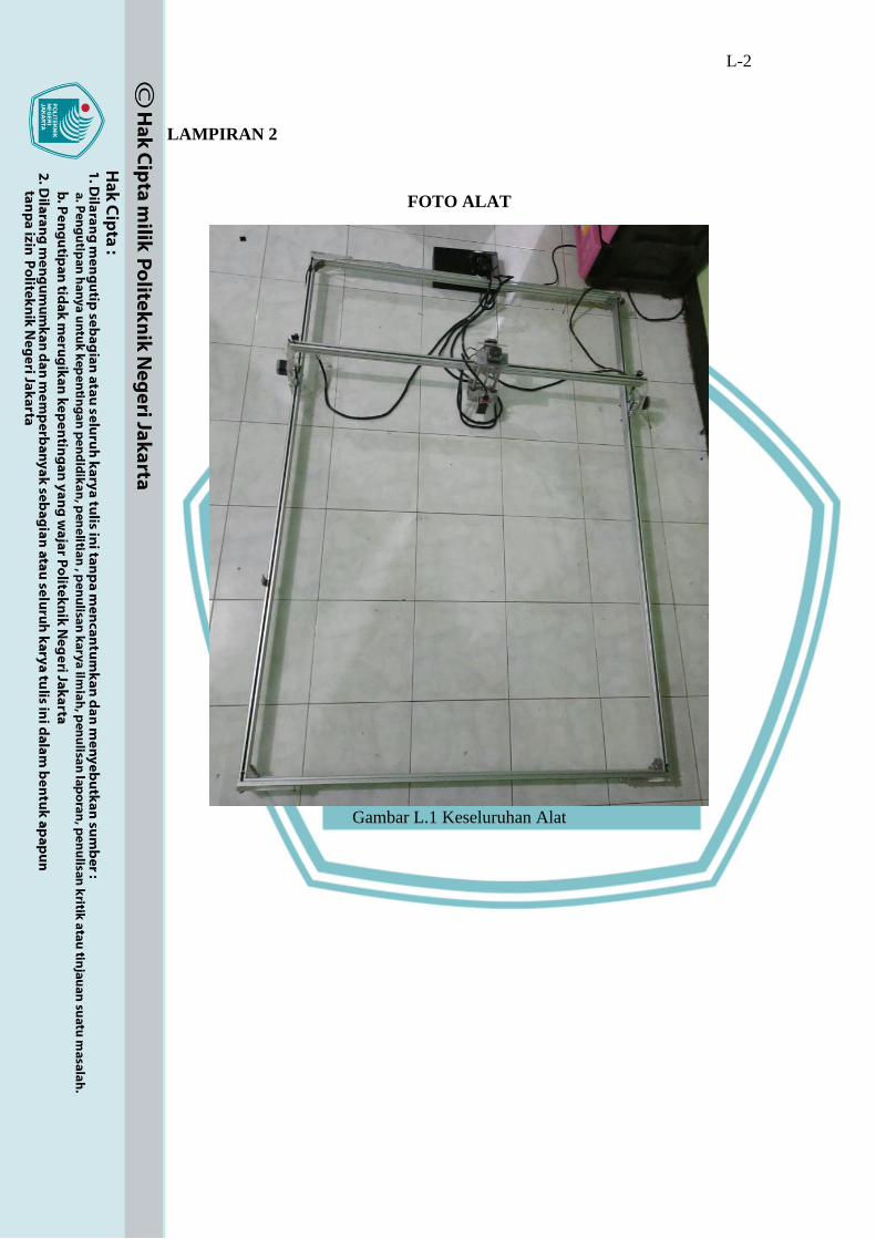
FOTO ALAT
Gambar L.1 Keseluruhan Alat
L-3
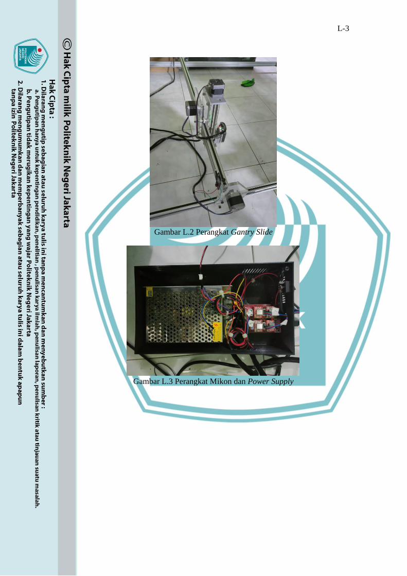
Gambar L.2 Perangkat Gantry Slide
Gambar L.3 Perangkat Mikon dan Power Supply
L-4
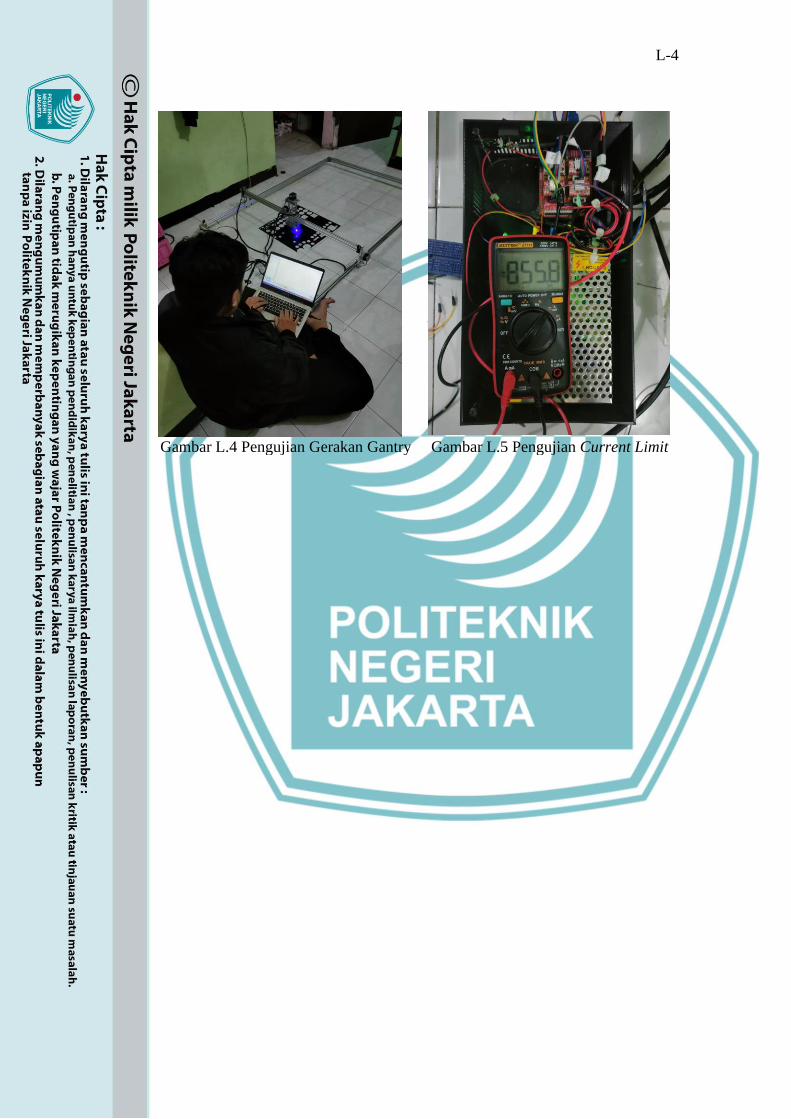
Gambar L.4 Pengujian Gerakan Gantry Gambar L.5 Pengujian Current Limit

L-5
LAMPIRAN 3
LISTING PROGRAM
/*
stepper.c - stepper motor driver: executes motion plans using stepper motors
Part of Grbl
Copyright (c) 2011-2016 Sungeun K. Jeon for Gnea Research LLC
Copyright (c) 2009-2011 Simen Svale Skogsrud
Grbl is free software: you can redistribute it and/or modify
it under the terms of the GNU General Public License as published by
the Free Software Foundation, either version 3 of the License, or
(at your option) any later version.
Grbl is distributed in the hope that it will be useful,
but WITHOUT ANY WARRANTY; without even the implied warranty of
MERCHANTABILITY or FITNESS FOR A PARTICULAR PURPOSE. See
the
GNU General Public License for more details.
You should have received a copy of the GNU General Public License
along with Grbl. If not, see <http://www.gnu.org/licenses/>.
*/
#include "grbl.h"
// Some useful constants.
#define DT_SEGMENT (1.0/(ACCELERATION_TICKS_PER_SECOND*60.0))
// min/segment

L-6
#define REQ_MM_INCREMENT_SCALAR 1.25
#define RAMP_ACCEL 0
#define RAMP_CRUISE 1
#define RAMP_DECEL 2
#define RAMP_DECEL_OVERRIDE 3
#define PREP_FLAG_RECALCULATE bit(0)
#define PREP_FLAG_HOLD_PARTIAL_BLOCK bit(1)
#define PREP_FLAG_PARKING bit(2)
#define PREP_FLAG_DECEL_OVERRIDE bit(3)
// Define Adaptive Multi-Axis Step-Smoothing(AMASS) levels and cutoff
frequencies. The highest level
// frequency bin starts at 0Hz and ends at its cutoff frequency. The next lower
level frequency bin
// starts at the next higher cutoff frequency, and so on. The cutoff frequencies for
each level must
// be considered carefully against how much it over-drives the stepper ISR, the
accuracy of the 16-bit
// timer, and the CPU overhead. Level 0 (no AMASS, normal operation)
frequency bin starts at the
// Level 1 cutoff frequency and up to as fast as the CPU allows (over 30kHz in
limited testing).
// NOTE: AMASS cutoff frequency multiplied by ISR overdrive factor must not
exceed maximum step frequency.
// NOTE: Current settings are set to overdrive the ISR to no more than 16kHz,
balancing CPU overhead
// and timer accuracy. Do not alter these settings unless you know what you are
doing.
#ifdef ADAPTIVE_MULTI_AXIS_STEP_SMOOTHING
#define MAX_AMASS_LEVEL 3

L-7
// AMASS_LEVEL0: Normal operation. No AMASS. No upper cutoff
frequency. Starts at LEVEL1 cutoff frequency.
#define AMASS_LEVEL1 (F_CPU/8000) // Over-drives ISR (x2).
Defined as F_CPU/(Cutoff frequency in Hz)
#define AMASS_LEVEL2 (F_CPU/4000) // Over-drives ISR (x4)
#define AMASS_LEVEL3 (F_CPU/2000) // Over-drives ISR (x8)
#if MAX_AMASS_LEVEL <= 0
error "AMASS must have 1 or more levels to operate correctly."
#endif
#endif
// Stores the planner block Bresenham algorithm execution data for the segments
in the segment
// buffer. Normally, this buffer is partially in-use, but, for the worst case scenario,
it will
// never exceed the number of accessible stepper buffer segments
(SEGMENT_BUFFER_SIZE-1).
// NOTE: This data is copied from the prepped planner blocks so that the planner
blocks may be
// discarded when entirely consumed and completed by the segment buffer. Also,
AMASS alters this
// data for its own use.
typedef struct {
uint32_t steps[N_AXIS];
uint32_t step_event_count;
uint8_t direction_bits;
#ifdef ENABLE_DUAL_AXIS
uint8_t direction_bits_dual;
#endif
#ifdef VARIABLE_SPINDLE

L-8
uint8_t is_pwm_rate_adjusted; // Tracks motions that require constant laser
power/rate
#endif
} st_block_t;
static st_block_t st_block_buffer[SEGMENT_BUFFER_SIZE-1];
// Primary stepper segment ring buffer. Contains small, short line segments for the
stepper
// algorithm to execute, which are "checked-out" incrementally from the first
block in the
// planner buffer. Once "checked-out", the steps in the segments buffer cannot be
modified by
// the planner, where the remaining planner block steps still can.
typedef struct {
uint16_t n_step; // Number of step events to be executed for this segment
uint16_t cycles_per_tick; // Step distance traveled per ISR tick, aka step rate.
uint8_t st_block_index; // Stepper block data index. Uses this information to
execute this segment.
#ifdef ADAPTIVE_MULTI_AXIS_STEP_SMOOTHING
uint8_t amass_level; // Indicates AMASS level for the ISR to execute this
segment
#else
uint8_t prescaler; // Without AMASS, a prescaler is required to adjust for
slow timing.
#endif
#ifdef VARIABLE_SPINDLE
uint8_t spindle_pwm;
#endif
} segment_t;
static segment_t segment_buffer[SEGMENT_BUFFER_SIZE];
// Stepper ISR data struct. Contains the running data for the main stepper ISR.

L-9
typedef struct {
// Used by the bresenham line algorithm
uint32_t counter_x, // Counter variables for the bresenham line tracer
counter_y,
counter_z;
#ifdef STEP_PULSE_DELAY
uint8_t step_bits; // Stores out_bits output to complete the step pulse delay
#endif
uint8_t execute_step; // Flags step execution for each interrupt.
uint8_t step_pulse_time; // Step pulse reset time after step rise
uint8_t step_outbits; // The next stepping-bits to be output
uint8_t dir_outbits;
#ifdef ENABLE_DUAL_AXIS
uint8_t step_outbits_dual;
uint8_t dir_outbits_dual;
#endif
#ifdef ADAPTIVE_MULTI_AXIS_STEP_SMOOTHING
uint32_t steps[N_AXIS];
#endif
uint16_t step_count; // Steps remaining in line segment motion
uint8_t exec_block_index; // Tracks the current st_block index. Change indicates
new block.
st_block_t *exec_block; // Pointer to the block data for the segment being
executed
segment_t *exec_segment; // Pointer to the segment being executed
} stepper_t;
static stepper_t st;
// Step segment ring buffer indices
static volatile uint8_t segment_buffer_tail;

L-10
static uint8_t segment_buffer_head;
static uint8_t segment_next_head;
// Step and direction port invert masks.
static uint8_t step_port_invert_mask;
static uint8_t dir_port_invert_mask;
#ifdef ENABLE_DUAL_AXIS
static uint8_t step_port_invert_mask_dual;
static uint8_t dir_port_invert_mask_dual;
#endif
// Used to avoid ISR nesting of the "Stepper Driver Interrupt". Should never occur
though.
static volatile uint8_t busy;
// Pointers for the step segment being prepped from the planner buffer. Accessed
only by the
// main program. Pointers may be planning segments or planner blocks ahead of
what being executed.
static plan_block_t *pl_block; // Pointer to the planner block being prepped
static st_block_t *st_prep_block; // Pointer to the stepper block data being
prepped
// Segment preparation data struct. Contains all the necessary information to
compute new segments
// based on the current executing planner block.
typedef struct {
uint8_t st_block_index; // Index of stepper common data block being prepped
uint8_t recalculate_flag;
float dt_remainder;
float steps_remaining;

L-11
float step_per_mm;
float req_mm_increment;
#ifdef PARKING_ENABLE
uint8_t last_st_block_index;
float last_steps_remaining;
float last_step_per_mm;
float last_dt_remainder;
#endif
uint8_t ramp_type; // Current segment ramp state
float mm_complete; // End of velocity profile from end of current planner
block in (mm).
// NOTE: This value must coincide with a step(no mantissa) when
converted.
float current_speed; // Current speed at the end of the segment buffer
(mm/min)
float maximum_speed; // Maximum speed of executing block. Not always
nominal speed. (mm/min)
float exit_speed; // Exit speed of executing block (mm/min)
float accelerate_until; // Acceleration ramp end measured from end of block
(mm)
float decelerate_after; // Deceleration ramp start measured from end of block
(mm)
#ifdef VARIABLE_SPINDLE
float inv_rate; // Used by PWM laser mode to speed up segment calculations.
uint8_t current_spindle_pwm;
#endif
} st_prep_t;
static st_prep_t prep;

L-12
/* BLOCK VELOCITY PROFILE DEFINITION
__________________________
/| |\ _________________ ^
/ | | \ /| |\ |
/ | | \ / | | \ s
/ | | | | | \ p
/ | | | | | \ e
+-----+------------------------+---+--+---------------+----+ e
| BLOCK 1 ^ BLOCK 2 | d
|
time -----> EXAMPLE: Block 2 entry speed is at max junction
velocity
The planner block buffer is planned assuming constant acceleration velocity
profiles and are
continuously joined at block junctions as shown above. However, the planner
only actively computes
the block entry speeds for an optimal velocity plan, but does not compute the
block internal
velocity profiles. These velocity profiles are computed ad-hoc as they are
executed by the
stepper algorithm and consists of only 7 possible types of profiles: cruise-only,
cruise-
deceleration, acceleration-cruise, acceleration-only, deceleration-only, full-
trapezoid, and
triangle(no cruise).
maximum_speed (< nominal_speed) -> +
+--------+ <- maximum_speed (= nominal_speed) /|\
/ \ / | \
current_speed -> + \ / | + <- exit_speed

L-13
| + <- exit_speed / | |
+-------------+ current_speed -> +----+--+
time --> ^ ^ ^ ^
| | | |
decelerate_after(in mm) decelerate_after(in mm)
^ ^ ^ ^
| | | |
accelerate_until(in mm) accelerate_until(in mm)
The step segment buffer computes the executing block velocity profile and
tracks the critical
parameters for the stepper algorithm to accurately trace the profile. These critical
parameters
are shown and defined in the above illustration.
*/
// Stepper state initialization. Cycle should only start if the st.cycle_start flag is
// enabled. Startup init and limits call this function but shouldn't start the cycle.
void st_wake_up()
{
// Enable stepper drivers.
if (bit_istrue(settings.flags,BITFLAG_INVERT_ST_ENABLE)) {
STEPPERS_DISABLE_PORT |= (1<<STEPPERS_DISABLE_BIT); }
else { STEPPERS_DISABLE_PORT &= ~(1<<STEPPERS_DISABLE_BIT); }
// Initialize stepper output bits to ensure first ISR call does not step.
st.step_outbits = step_port_invert_mask;
// Initialize step pulse timing from settings. Here to ensure updating after re-
writing.
#ifdef STEP_PULSE_DELAY

L-14
// Set total step pulse time after direction pin set. Ad hoc computation from
oscilloscope.
st.step_pulse_time = -(((settings.pulse_microseconds+STEP_PULSE_DELAY-
2)*TICKS_PER_MICROSECOND) >> 3);
// Set delay between direction pin write and step command.
OCR0A = -(((settings.pulse_microseconds)*TICKS_PER_MICROSECOND)
>> 3);
#else // Normal operation
// Set step pulse time. Ad hoc computation from oscilloscope. Uses two's
complement.
st.step_pulse_time = -(((settings.pulse_microseconds-
2)*TICKS_PER_MICROSECOND) >> 3);
#endif
// Enable Stepper Driver Interrupt
TIMSK1 |= (1<<OCIE1A);
}
// Stepper shutdown
void st_go_idle()
{
// Disable Stepper Driver Interrupt. Allow Stepper Port Reset Interrupt to finish,
if active.
TIMSK1 &= ~(1<<OCIE1A); // Disable Timer1 interrupt
TCCR1B = (TCCR1B & ~((1<<CS12) | (1<<CS11))) | (1<<CS10); // Reset
clock to no prescaling.
busy = false;
// Set stepper driver idle state, disabled or enabled, depending on settings and
circumstances.
bool pin_state = false; // Keep enabled.

L-15
if (((settings.stepper_idle_lock_time != 0xff) || sys_rt_exec_alarm || sys.state ==
STATE_SLEEP) && sys.state != STATE_HOMING) {
// Force stepper dwell to lock axes for a defined amount of time to ensure the
axes come to a complete
// stop and not drift from residual inertial forces at the end of the last
movement.
delay_ms(settings.stepper_idle_lock_time);
pin_state = true; // Override. Disable steppers.
}
if (bit_istrue(settings.flags,BITFLAG_INVERT_ST_ENABLE)) { pin_state =
!pin_state; } // Apply pin invert.
if (pin_state) { STEPPERS_DISABLE_PORT |=
(1<<STEPPERS_DISABLE_BIT); }
else { STEPPERS_DISABLE_PORT &= ~(1<<STEPPERS_DISABLE_BIT); }
}
/* "The Stepper Driver Interrupt" - This timer interrupt is the workhorse of Grbl.
Grbl employs
the venerable Bresenham line algorithm to manage and exactly synchronize
multi-axis moves.
Unlike the popular DDA algorithm, the Bresenham algorithm is not susceptible
to numerical
round-off errors and only requires fast integer counters, meaning low
computational overhead
and maximizing the Arduino's capabilities. However, the downside of the
Bresenham algorithm
is, for certain multi-axis motions, the non-dominant axes may suffer from un-
smooth step
pulse trains, or aliasing, which can lead to strange audible noises or shaking.
This is

L-16
particularly noticeable or may cause motion issues at low step frequencies (0-
5kHz), but
is usually not a physical problem at higher frequencies, although audible.
To improve Bresenham multi-axis performance, Grbl uses what we call an
Adaptive Multi-Axis
Step Smoothing (AMASS) algorithm, which does what the name implies. At
lower step frequencies,
AMASS artificially increases the Bresenham resolution without effecting the
algorithm's
innate exactness. AMASS adapts its resolution levels automatically depending
on the step
frequency to be executed, meaning that for even lower step frequencies the step
smoothing
level increases. Algorithmically, AMASS is acheived by a simple bit-shifting of
the Bresenham
step count for each AMASS level. For example, for a Level 1 step smoothing,
we bit shift
the Bresenham step event count, effectively multiplying it by 2, while the axis
step counts
remain the same, and then double the stepper ISR frequency. In effect, we are
allowing the
non-dominant Bresenham axes step in the intermediate ISR tick, while the
dominant axis is
stepping every two ISR ticks, rather than every ISR tick in the traditional sense.
At AMASS
Level 2, we simply bit-shift again, so the non-dominant Bresenham axes can
step within any
of the four ISR ticks, the dominant axis steps every four ISR ticks, and
quadruple the
stepper ISR frequency. And so on. This, in effect, virtually eliminates multi-axis
aliasing

L-17
issues with the Bresenham algorithm and does not significantly alter Grbl's
performance, but
in fact, more efficiently utilizes unused CPU cycles overall throughout all
configurations.
AMASS retains the Bresenham algorithm exactness by requiring that it always
executes a full
Bresenham step, regardless of AMASS Level. Meaning that for an AMASS
Level 2, all four
intermediate steps must be completed such that baseline Bresenham (Level 0)
count is always
retained. Similarly, AMASS Level 3 means all eight intermediate steps must be
executed.
Although the AMASS Levels are in reality arbitrary, where the baseline
Bresenham counts can
be multiplied by any integer value, multiplication by powers of two are simply
used to ease
CPU overhead with bitshift integer operations.
This interrupt is simple and dumb by design. All the computational heavy-
lifting, as in
determining accelerations, is performed elsewhere. This interrupt pops pre-
computed segments,
defined as constant velocity over n number of steps, from the step segment
buffer and then
executes them by pulsing the stepper pins appropriately via the Bresenham
algorithm. This
ISR is supported by The Stepper Port Reset Interrupt which it uses to reset the
stepper port
after each pulse. The bresenham line tracer algorithm controls all stepper
outputs
simultaneously with these two interrupts.

L-18
NOTE: This interrupt must be as efficient as possible and complete before the
next ISR tick,
which for Grbl must be less than 33.3usec (@30kHz ISR rate). Oscilloscope
measured time in
ISR is 5usec typical and 25usec maximum, well below requirement.
NOTE: This ISR expects at least one step to be executed per segment.
*/
// TODO: Replace direct updating of the int32 position counters in the ISR
somehow. Perhaps use smaller
// int8 variables and update position counters only when a segment completes.
This can get complicated
// with probing and homing cycles that require true real-time positions.
ISR(TIMER1_COMPA_vect)
{
if (busy) { return; } // The busy-flag is used to avoid reentering this interrupt
// Set the direction pins a couple of nanoseconds before we step the steppers
DIRECTION_PORT = (DIRECTION_PORT & ~DIRECTION_MASK) |
(st.dir_outbits & DIRECTION_MASK);
#ifdef ENABLE_DUAL_AXIS
DIRECTION_PORT_DUAL = (DIRECTION_PORT_DUAL &
~DIRECTION_MASK_DUAL) | (st.dir_outbits_dual &
DIRECTION_MASK_DUAL);
#endif
// Then pulse the stepping pins
#ifdef STEP_PULSE_DELAY
st.step_bits = (STEP_PORT & ~STEP_MASK) | st.step_outbits; // Store
out_bits to prevent overwriting.
#ifdef ENABLE_DUAL_AXIS
st.step_bits_dual = (STEP_PORT_DUAL & ~STEP_MASK_DUAL) |
st.step_outbits_dual;

L-19
#endif
#else // Normal operation
STEP_PORT = (STEP_PORT & ~STEP_MASK) | st.step_outbits;
#ifdef ENABLE_DUAL_AXIS
STEP_PORT_DUAL = (STEP_PORT_DUAL & ~STEP_MASK_DUAL) |
st.step_outbits_dual;
#endif
#endif
// Enable step pulse reset timer so that The Stepper Port Reset Interrupt can reset
the signal after
// exactly settings.pulse_microseconds microseconds, independent of the main
Timer1 prescaler.
TCNT0 = st.step_pulse_time; // Reload Timer0 counter
TCCR0B = (1<<CS01); // Begin Timer0. Full speed, 1/8 prescaler
busy = true;
sei(); // Re-enable interrupts to allow Stepper Port Reset Interrupt to fire on-time.
// NOTE: The remaining code in this ISR will finish before returning to
main program.
// If there is no step segment, attempt to pop one from the stepper buffer
if (st.exec_segment == NULL) {
// Anything in the buffer? If so, load and initialize next step segment.
if (segment_buffer_head != segment_buffer_tail) {
// Initialize new step segment and load number of steps to execute
st.exec_segment = &segment_buffer[segment_buffer_tail];
#ifndef ADAPTIVE_MULTI_AXIS_STEP_SMOOTHING
// With AMASS is disabled, set timer prescaler for segments with slow step
frequencies (< 250Hz).

L-20
TCCR1B = (TCCR1B & ~(0x07<<CS10)) | (st.exec_segment-
>prescaler<<CS10);
#endif
// Initialize step segment timing per step and load number of steps to execute.
OCR1A = st.exec_segment->cycles_per_tick;
st.step_count = st.exec_segment->n_step; // NOTE: Can sometimes be zero
when moving slow.
// If the new segment starts a new planner block, initialize stepper variables
and counters.
// NOTE: When the segment data index changes, this indicates a new planner
block.
if ( st.exec_block_index != st.exec_segment->st_block_index ) {
st.exec_block_index = st.exec_segment->st_block_index;
st.exec_block = &st_block_buffer[st.exec_block_index];
// Initialize Bresenham line and distance counters
st.counter_x = st.counter_y = st.counter_z = (st.exec_block-
>step_event_count >> 1);
}
st.dir_outbits = st.exec_block->direction_bits ^ dir_port_invert_mask;
#ifdef ENABLE_DUAL_AXIS
st.dir_outbits_dual = st.exec_block->direction_bits_dual ^
dir_port_invert_mask_dual;
#endif
#ifdef ADAPTIVE_MULTI_AXIS_STEP_SMOOTHING
// With AMASS enabled, adjust Bresenham axis increment counters
according to AMASS level.
st.steps[X_AXIS] = st.exec_block->steps[X_AXIS] >> st.exec_segment-
>amass_level;

L-21
st.steps[Y_AXIS] = st.exec_block->steps[Y_AXIS] >> st.exec_segment-
>amass_level;
st.steps[Z_AXIS] = st.exec_block->steps[Z_AXIS] >> st.exec_segment-
>amass_level;
#endif
#ifdef VARIABLE_SPINDLE
// Set real-time spindle output as segment is loaded, just prior to the first step.
spindle_set_speed(st.exec_segment->spindle_pwm);
#endif
} else {
// Segment buffer empty. Shutdown.
st_go_idle();
#ifdef VARIABLE_SPINDLE
// Ensure pwm is set properly upon completion of rate-controlled motion.
if (st.exec_block->is_pwm_rate_adjusted) {
spindle_set_speed(SPINDLE_PWM_OFF_VALUE); }
#endif
system_set_exec_state_flag(EXEC_CYCLE_STOP); // Flag main program for
cycle end
return; // Nothing to do but exit.
}
}
// Check probing state.
if (sys_probe_state == PROBE_ACTIVE) { probe_state_monitor(); }
// Reset step out bits.
st.step_outbits = 0;
#ifdef ENABLE_DUAL_AXIS

L-22
st.step_outbits_dual = 0;
#endif
// Execute step displacement profile by Bresenham line algorithm
#ifdef ADAPTIVE_MULTI_AXIS_STEP_SMOOTHING
st.counter_x += st.steps[X_AXIS];
#else
st.counter_x += st.exec_block->steps[X_AXIS];
#endif
if (st.counter_x > st.exec_block->step_event_count) {
st.step_outbits |= (1<<X_STEP_BIT);
#if defined(ENABLE_DUAL_AXIS) && (DUAL_AXIS_SELECT ==
X_AXIS)
st.step_outbits_dual = (1<<DUAL_STEP_BIT);
#endif
st.counter_x -= st.exec_block->step_event_count;
if (st.exec_block->direction_bits & (1<<X_DIRECTION_BIT)) {
sys_position[X_AXIS]--; }
else { sys_position[X_AXIS]++; }
}
#ifdef ADAPTIVE_MULTI_AXIS_STEP_SMOOTHING
st.counter_y += st.steps[Y_AXIS];
#else
st.counter_y += st.exec_block->steps[Y_AXIS];
#endif
if (st.counter_y > st.exec_block->step_event_count) {
st.step_outbits |= (1<<Y_STEP_BIT);
#if defined(ENABLE_DUAL_AXIS) && (DUAL_AXIS_SELECT ==
Y_AXIS)
st.step_outbits_dual = (1<<DUAL_STEP_BIT);
#endif
st.counter_y -= st.exec_block->step_event_count;

L-23
if (st.exec_block->direction_bits & (1<<Y_DIRECTION_BIT)) {
sys_position[Y_AXIS]--; }
else { sys_position[Y_AXIS]++; }
}
#ifdef ADAPTIVE_MULTI_AXIS_STEP_SMOOTHING
st.counter_z += st.steps[Z_AXIS];
#else
st.counter_z += st.exec_block->steps[Z_AXIS];
#endif
if (st.counter_z > st.exec_block->step_event_count) {
st.step_outbits |= (1<<Z_STEP_BIT);
st.counter_z -= st.exec_block->step_event_count;
if (st.exec_block->direction_bits & (1<<Z_DIRECTION_BIT)) {
sys_position[Z_AXIS]--; }
else { sys_position[Z_AXIS]++; }
}
// During a homing cycle, lock out and prevent desired axes from moving.
if (sys.state == STATE_HOMING) {
st.step_outbits &= sys.homing_axis_lock;
#ifdef ENABLE_DUAL_AXIS
st.step_outbits_dual &= sys.homing_axis_lock_dual;
#endif
}
st.step_count--; // Decrement step events count
if (st.step_count == 0) {
// Segment is complete. Discard current segment and advance segment
indexing.
st.exec_segment = NULL;
if ( ++segment_buffer_tail == SEGMENT_BUFFER_SIZE) {
segment_buffer_tail = 0; }

L-24
}
st.step_outbits ^= step_port_invert_mask; // Apply step port invert mask
#ifdef ENABLE_DUAL_AXIS
st.step_outbits_dual ^= step_port_invert_mask_dual;
#endif
busy = false;
}
/* The Stepper Port Reset Interrupt: Timer0 OVF interrupt handles the falling
edge of the step
pulse. This should always trigger before the next Timer1 COMPA interrupt and
independently
finish, if Timer1 is disabled after completing a move.
NOTE: Interrupt collisions between the serial and stepper interrupts can cause
delays by
a few microseconds, if they execute right before one another. Not a big deal, but
can
cause issues at high step rates if another high frequency asynchronous interrupt
is
added to Grbl.
*/
// This interrupt is enabled by ISR_TIMER1_COMPAREA when it sets the motor
port bits to execute
// a step. This ISR resets the motor port after a short period
(settings.pulse_microseconds)
// completing one step cycle.
ISR(TIMER0_OVF_vect)
{
// Reset stepping pins (leave the direction pins)

L-25
STEP_PORT = (STEP_PORT & ~STEP_MASK) | (step_port_invert_mask &
STEP_MASK);
#ifdef ENABLE_DUAL_AXIS
STEP_PORT_DUAL = (STEP_PORT_DUAL & ~STEP_MASK_DUAL) |
(step_port_invert_mask_dual & STEP_MASK_DUAL);
#endif
TCCR0B = 0; // Disable Timer0 to prevent re-entering this interrupt when it's not
needed.
}
#ifdef STEP_PULSE_DELAY
// This interrupt is used only when STEP_PULSE_DELAY is enabled. Here, the
step pulse is
// initiated after the STEP_PULSE_DELAY time period has elapsed. The ISR
TIMER2_OVF interrupt
// will then trigger after the appropriate settings.pulse_microseconds, as in
normal operation.
// The new timing between direction, step pulse, and step complete events are
setup in the
// st_wake_up() routine.
ISR(TIMER0_COMPA_vect)
{
STEP_PORT = st.step_bits; // Begin step pulse.
#ifdef ENABLE_DUAL_AXIS
STEP_PORT_DUAL = st.step_bits_dual;
#endif
}
#endif
// Generates the step and direction port invert masks used in the Stepper Interrupt
Driver.
void st_generate_step_dir_invert_masks()
L-26
{
uint8_t idx;
step_port_invert_mask = 0;
dir_port_invert_mask = 0;
for (idx=0; idx<N_AXIS; idx++) {
if (bit_istrue(settings.step_invert_mask,bit(idx))) { step_port_invert_mask |=
get_step_pin_mask(idx); }
if (bit_istrue(settings.dir_invert_mask,bit(idx))) { dir_port_invert_mask |=
get_direction_pin_mask(idx); }
}
#ifdef ENABLE_DUAL_AXIS
step_port_invert_mask_dual = 0;
dir_port_invert_mask_dual = 0;
// NOTE: Dual axis invert uses the N_AXIS bit to set step and direction invert
pins.
if (bit_istrue(settings.step_invert_mask,bit(N_AXIS))) {
step_port_invert_mask_dual = (1<<DUAL_STEP_BIT); }
if (bit_istrue(settings.dir_invert_mask,bit(N_AXIS))) {
dir_port_invert_mask_dual = (1<<DUAL_DIRECTION_BIT); }
#endif
}
// Reset and clear stepper subsystem variables
void st_reset()
{
// Initialize stepper driver idle state.
st_go_idle();
// Initialize stepper algorithm variables.
memset(&prep, 0, sizeof(st_prep_t));
memset(&st, 0, sizeof(stepper_t));

L-27
st.exec_segment = NULL;
pl_block = NULL; // Planner block pointer used by segment buffer
segment_buffer_tail = 0;
segment_buffer_head = 0; // empty = tail
segment_next_head = 1;
busy = false;
st_generate_step_dir_invert_masks();
st.dir_outbits = dir_port_invert_mask; // Initialize direction bits to default.
// Initialize step and direction port pins.
STEP_PORT = (STEP_PORT & ~STEP_MASK) | step_port_invert_mask;
DIRECTION_PORT = (DIRECTION_PORT & ~DIRECTION_MASK) |
dir_port_invert_mask;
#ifdef ENABLE_DUAL_AXIS
st.dir_outbits_dual = dir_port_invert_mask_dual;
STEP_PORT_DUAL = (STEP_PORT_DUAL & ~STEP_MASK_DUAL) |
step_port_invert_mask_dual;
DIRECTION_PORT_DUAL = (DIRECTION_PORT_DUAL &
~DIRECTION_MASK_DUAL) | dir_port_invert_mask_dual;
#endif
}
// Initialize and start the stepper motor subsystem
void stepper_init()
{
// Configure step and direction interface pins
STEP_DDR |= STEP_MASK;
STEPPERS_DISABLE_DDR |= 1<<STEPPERS_DISABLE_BIT;
DIRECTION_DDR |= DIRECTION_MASK;
L-28
#ifdef ENABLE_DUAL_AXIS
STEP_DDR_DUAL |= STEP_MASK_DUAL;
DIRECTION_DDR_DUAL |= DIRECTION_MASK_DUAL;
#endif
// Configure Timer 1: Stepper Driver Interrupt
TCCR1B &= ~(1<<WGM13); // waveform generation = 0100 = CTC
TCCR1B |= (1<<WGM12);
TCCR1A &= ~((1<<WGM11) | (1<<WGM10));
TCCR1A &= ~((1<<COM1A1) | (1<<COM1A0) | (1<<COM1B1) |
(1<<COM1B0)); // Disconnect OC1 output
// TCCR1B = (TCCR1B & ~((1<<CS12) | (1<<CS11))) | (1<<CS10); // Set in
st_go_idle().
// TIMSK1 &= ~(1<<OCIE1A); // Set in st_go_idle().
// Configure Timer 0: Stepper Port Reset Interrupt
TIMSK0 &= ~((1<<OCIE0B) | (1<<OCIE0A) | (1<<TOIE0)); // Disconnect
OC0 outputs and OVF interrupt.
TCCR0A = 0; // Normal operation
TCCR0B = 0; // Disable Timer0 until needed
TIMSK0 |= (1<<TOIE0); // Enable Timer0 overflow interrupt
#ifdef STEP_PULSE_DELAY
TIMSK0 |= (1<<OCIE0A); // Enable Timer0 Compare Match A interrupt
#endif
}
// Called by planner_recalculate() when the executing block is updated by the new
plan.
void st_update_plan_block_parameters()
{

L-29
if (pl_block != NULL) { // Ignore if at start of a new block.
prep.recalculate_flag |= PREP_FLAG_RECALCULATE;
pl_block->entry_speed_sqr = prep.current_speed*prep.current_speed; // Update
entry speed.
pl_block = NULL; // Flag st_prep_segment() to load and check active velocity
profile.
}
}
// Increments the step segment buffer block data ring buffer.
static uint8_t st_next_block_index(uint8_t block_index)
{
block_index++;
if ( block_index == (SEGMENT_BUFFER_SIZE-1) ) { return(0); }
return(block_index);
}
#ifdef PARKING_ENABLE
// Changes the run state of the step segment buffer to execute the special parking
motion.
void st_parking_setup_buffer()
{
// Store step execution data of partially completed block, if necessary.
if (prep.recalculate_flag & PREP_FLAG_HOLD_PARTIAL_BLOCK) {
prep.last_st_block_index = prep.st_block_index;
prep.last_steps_remaining = prep.steps_remaining;
prep.last_dt_remainder = prep.dt_remainder;
prep.last_step_per_mm = prep.step_per_mm;
}
// Set flags to execute a parking motion

L-30
prep.recalculate_flag |= PREP_FLAG_PARKING;
prep.recalculate_flag &= ~(PREP_FLAG_RECALCULATE);
pl_block = NULL; // Always reset parking motion to reload new block.
}
// Restores the step segment buffer to the normal run state after a parking motion.
void st_parking_restore_buffer()
{
// Restore step execution data and flags of partially completed block, if
necessary.
if (prep.recalculate_flag & PREP_FLAG_HOLD_PARTIAL_BLOCK) {
st_prep_block = &st_block_buffer[prep.last_st_block_index];
prep.st_block_index = prep.last_st_block_index;
prep.steps_remaining = prep.last_steps_remaining;
prep.dt_remainder = prep.last_dt_remainder;
prep.step_per_mm = prep.last_step_per_mm;
prep.recalculate_flag = (PREP_FLAG_HOLD_PARTIAL_BLOCK |
PREP_FLAG_RECALCULATE);
prep.req_mm_increment =
REQ_MM_INCREMENT_SCALAR/prep.step_per_mm; // Recompute this value.
} else {
prep.recalculate_flag = false;
}
pl_block = NULL; // Set to reload next block.
}
#endif
/* Prepares step segment buffer. Continuously called from main program.

L-31
The segment buffer is an intermediary buffer interface between the execution of
steps
by the stepper algorithm and the velocity profiles generated by the planner. The
stepper
algorithm only executes steps within the segment buffer and is filled by the
main program
when steps are "checked-out" from the first block in the planner buffer. This
keeps the
step execution and planning optimization processes atomic and protected from
each other.
The number of steps "checked-out" from the planner buffer and the number of
segments in
the segment buffer is sized and computed such that no operation in the main
program takes
longer than the time it takes the stepper algorithm to empty it before refilling it.
Currently, the segment buffer conservatively holds roughly up to 40-50 msec of
steps.
NOTE: Computation units are in steps, millimeters, and minutes.
*/
void st_prep_buffer()
{
// Block step prep buffer, while in a suspend state and there is no suspend motion
to execute.
if (bit_istrue(sys.step_control,STEP_CONTROL_END_MOTION)) { return; }
while (segment_buffer_tail != segment_next_head) { // Check if we need to fill
the buffer.
// Determine if we need to load a new planner block or if the block needs to be
recomputed.
if (pl_block == NULL) {

L-32
// Query planner for a queued block
if (sys.step_control & STEP_CONTROL_EXECUTE_SYS_MOTION) {
pl_block = plan_get_system_motion_block(); }
else { pl_block = plan_get_current_block(); }
if (pl_block == NULL) { return; } // No planner blocks. Exit.
// Check if we need to only recompute the velocity profile or load a new block.
if (prep.recalculate_flag & PREP_FLAG_RECALCULATE) {
#ifdef PARKING_ENABLE
if (prep.recalculate_flag & PREP_FLAG_PARKING) {
prep.recalculate_flag &= ~(PREP_FLAG_RECALCULATE); }
else { prep.recalculate_flag = false; }
#else
prep.recalculate_flag = false;
#endif
} else {
// Load the Bresenham stepping data for the block.
prep.st_block_index = st_next_block_index(prep.st_block_index);
// Prepare and copy Bresenham algorithm segment data from the new planner
block, so that
// when the segment buffer completes the planner block, it may be discarded
when the
// segment buffer finishes the prepped block, but the stepper ISR is still
executing it.
st_prep_block = &st_block_buffer[prep.st_block_index];
st_prep_block->direction_bits = pl_block->direction_bits;
#ifdef ENABLE_DUAL_AXIS
#if (DUAL_AXIS_SELECT == X_AXIS)
L-33
if (st_prep_block->direction_bits & (1<<X_DIRECTION_BIT)) {
#elif (DUAL_AXIS_SELECT == Y_AXIS)
if (st_prep_block->direction_bits & (1<<Y_DIRECTION_BIT)) {
#endif
st_prep_block->direction_bits_dual = (1<<DUAL_DIRECTION_BIT);
} else { st_prep_block->direction_bits_dual = 0; }
#endif
uint8_t idx;
#ifndef ADAPTIVE_MULTI_AXIS_STEP_SMOOTHING
for (idx=0; idx<N_AXIS; idx++) { st_prep_block->steps[idx] = (pl_block-
>steps[idx] << 1); }
st_prep_block->step_event_count = (pl_block->step_event_count << 1);
#else
// With AMASS enabled, simply bit-shift multiply all Bresenham data by
the max AMASS
// level, such that we never divide beyond the original data anywhere in the
algorithm.
// If the original data is divided, we can lose a step from integer roundoff.
for (idx=0; idx<N_AXIS; idx++) { st_prep_block->steps[idx] = pl_block-
>steps[idx] << MAX_AMASS_LEVEL; }
st_prep_block->step_event_count = pl_block->step_event_count <<
MAX_AMASS_LEVEL;
#endif
// Initialize segment buffer data for generating the segments.
prep.steps_remaining = (float)pl_block->step_event_count;
prep.step_per_mm = prep.steps_remaining/pl_block->millimeters;
prep.req_mm_increment =
REQ_MM_INCREMENT_SCALAR/prep.step_per_mm;
prep.dt_remainder = 0.0; // Reset for new segment block

L-34
if ((sys.step_control & STEP_CONTROL_EXECUTE_HOLD) ||
(prep.recalculate_flag & PREP_FLAG_DECEL_OVERRIDE)) {
// New block loaded mid-hold. Override planner block entry speed to
enforce deceleration.
prep.current_speed = prep.exit_speed;
pl_block->entry_speed_sqr = prep.exit_speed*prep.exit_speed;
prep.recalculate_flag &= ~(PREP_FLAG_DECEL_OVERRIDE);
} else {
prep.current_speed = sqrt(pl_block->entry_speed_sqr);
}
#ifdef VARIABLE_SPINDLE
// Setup laser mode variables. PWM rate adjusted motions will always
complete a motion with the
// spindle off.
st_prep_block->is_pwm_rate_adjusted = false;
if (settings.flags & BITFLAG_LASER_MODE) {
if (pl_block->condition & PL_COND_FLAG_SPINDLE_CCW) {
// Pre-compute inverse programmed rate to speed up PWM updating per
step segment.
prep.inv_rate = 1.0/pl_block->programmed_rate;
st_prep_block->is_pwm_rate_adjusted = true;
}
}
#endif
}
/* ---------------------------------------------------------------------
------------
Compute the velocity profile of a new planner block based
on its entry and exit

L-35
speeds, or recompute the profile of a partially-completed
planner block if the
planner has updated it. For a commanded forced-
deceleration, such as from a feed
hold, override the planner velocities and decelerate to the
target exit speed.
*/
prep.mm_complete = 0.0; // Default velocity profile
complete at 0.0mm from end of block.
float inv_2_accel = 0.5/pl_block->acceleration;
if (sys.step_control &
STEP_CONTROL_EXECUTE_HOLD) { // [Forced Deceleration to Zero
Velocity]
// Compute velocity profile parameters for a feed
hold in-progress. This profile overrides
// the planner block profile, enforcing a deceleration
to zero speed.
prep.ramp_type = RAMP_DECEL;
// Compute decelerate distance relative to end of
block.
float decel_dist = pl_block->millimeters -
inv_2_accel*pl_block->entry_speed_sqr;
if (decel_dist < 0.0) {
// Deceleration through entire planner block.
End of feed hold is not in this block.
prep.exit_speed = sqrt(pl_block-
>entry_speed_sqr-2*pl_block->acceleration*pl_block->millimeters);
} else {
prep.mm_complete = decel_dist; // End of
feed hold.
prep.exit_speed = 0.0;
}

L-36
} else { // [Normal Operation]
// Compute or recompute velocity profile parameters
of the prepped planner block.
prep.ramp_type = RAMP_ACCEL; // Initialize as
acceleration ramp.
prep.accelerate_until = pl_block->millimeters;
float exit_speed_sqr;
float nominal_speed;
if (sys.step_control & STEP_CONTROL_EXECUTE_SYS_MOTION) {
prep.exit_speed = exit_speed_sqr = 0.0; // Enforce stop at end of system
motion.
} else {
exit_speed_sqr = plan_get_exec_block_exit_speed_sqr();
prep.exit_speed = sqrt(exit_speed_sqr);
}
nominal_speed = plan_compute_profile_nominal_speed(pl_block);
float nominal_speed_sqr =
nominal_speed*nominal_speed;
float intersect_distance =
0.5*(pl_block-
>millimeters+inv_2_accel*(pl_block->entry_speed_sqr-exit_speed_sqr));
if (pl_block->entry_speed_sqr > nominal_speed_sqr) { // Only occurs during
override reductions.
prep.accelerate_until = pl_block->millimeters - inv_2_accel*(pl_block-
>entry_speed_sqr-nominal_speed_sqr);
if (prep.accelerate_until <= 0.0) { // Deceleration-only.
prep.ramp_type = RAMP_DECEL;
// prep.decelerate_after = pl_block->millimeters;
// prep.maximum_speed = prep.current_speed;
L-37
// Compute override block exit speed since it doesn't match the planner
exit speed.
prep.exit_speed = sqrt(pl_block->entry_speed_sqr - 2*pl_block-
>acceleration*pl_block->millimeters);
prep.recalculate_flag |= PREP_FLAG_DECEL_OVERRIDE; // Flag to
load next block as deceleration override.
// TODO: Determine correct handling of parameters in deceleration-only.
// Can be tricky since entry speed will be current speed, as in feed holds.
// Also, look into near-zero speed handling issues with this.
} else {
// Decelerate to cruise or cruise-decelerate types. Guaranteed to intersect
updated plan.
prep.decelerate_after = inv_2_accel*(nominal_speed_sqr-exit_speed_sqr);
// Should always be >= 0.0 due to planner reinit.
prep.maximum_speed = nominal_speed;
prep.ramp_type = RAMP_DECEL_OVERRIDE;
}
} else if (intersect_distance > 0.0) {
if (intersect_distance < pl_block-
>millimeters) { // Either trapezoid or triangle types
// NOTE: For acceleration-cruise and
cruise-only types, following calculation will be 0.0.
prep.decelerate_after =
inv_2_accel*(nominal_speed_sqr-exit_speed_sqr);
if (prep.decelerate_after <
intersect_distance) { // Trapezoid type
prep.maximum_speed =
nominal_speed;

L-38
if (pl_block-
>entry_speed_sqr == nominal_speed_sqr) {
// Cruise-deceleration
or cruise-only type.
prep.ramp_type =
RAMP_CRUISE;
} else {
// Full-trapezoid or
acceleration-cruise types
prep.accelerate_until -
= inv_2_accel*(nominal_speed_sqr-pl_block->entry_speed_sqr);
}
} else { // Triangle type
prep.accelerate_until =
intersect_distance;
prep.decelerate_after =
intersect_distance;
prep.maximum_speed =
sqrt(2.0*pl_block->acceleration*intersect_distance+exit_speed_sqr);
}
} else { // Deceleration-only type
prep.ramp_type = RAMP_DECEL;
// prep.decelerate_after = pl_block->millimeters;
// prep.maximum_speed = prep.current_speed;
}
} else { // Acceleration-only type
prep.accelerate_until = 0.0;
// prep.decelerate_after = 0.0;
prep.maximum_speed = prep.exit_speed;
}
}

L-39
#ifdef VARIABLE_SPINDLE
bit_true(sys.step_control, STEP_CONTROL_UPDATE_SPINDLE_PWM);
// Force update whenever updating block.
#endif
}
// Initialize new segment
segment_t *prep_segment = &segment_buffer[segment_buffer_head];
// Set new segment to point to the current segment data block.
prep_segment->st_block_index = prep.st_block_index;
/*------------------------------------------------------------------------------------
Compute the average velocity of this new segment by determining the total
distance
traveled over the segment time DT_SEGMENT. The following code first
attempts to create
a full segment based on the current ramp conditions. If the segment time is
incomplete
when terminating at a ramp state change, the code will continue to loop
through the
progressing ramp states to fill the remaining segment execution time.
However, if
an incomplete segment terminates at the end of the velocity profile, the
segment is
considered completed despite having a truncated execution time less than
DT_SEGMENT.
The velocity profile is always assumed to progress through the ramp
sequence:
acceleration ramp, cruising state, and deceleration ramp. Each ramp's travel
distance

L-40
may range from zero to the length of the block. Velocity profiles can end
either at
the end of planner block (typical) or mid-block at the end of a forced
deceleration,
such as from a feed hold.
*/
float dt_max = DT_SEGMENT; // Maximum segment time
float dt = 0.0; // Initialize segment time
float time_var = dt_max; // Time worker variable
float mm_var; // mm-Distance worker variable
float speed_var; // Speed worker variable
float mm_remaining = pl_block->millimeters; // New segment distance from
end of block.
float minimum_mm = mm_remaining-prep.req_mm_increment; // Guarantee at
least one step.
if (minimum_mm < 0.0) { minimum_mm = 0.0; }
do {
switch (prep.ramp_type) {
case RAMP_DECEL_OVERRIDE:
speed_var = pl_block->acceleration*time_var;
if (prep.current_speed-prep.maximum_speed <= speed_var) {
// Cruise or cruise-deceleration types only for deceleration override.
mm_remaining = prep.accelerate_until;
time_var = 2.0*(pl_block->millimeters-
mm_remaining)/(prep.current_speed+prep.maximum_speed);
prep.ramp_type = RAMP_CRUISE;
prep.current_speed = prep.maximum_speed;
} else { // Mid-deceleration override ramp.
mm_remaining -= time_var*(prep.current_speed - 0.5*speed_var);
prep.current_speed -= speed_var;
}

L-41
break;
case RAMP_ACCEL:
// NOTE: Acceleration ramp only computes during first do-while loop.
speed_var = pl_block->acceleration*time_var;
mm_remaining -= time_var*(prep.current_speed + 0.5*speed_var);
if (mm_remaining < prep.accelerate_until) { // End of acceleration ramp.
// Acceleration-cruise, acceleration-deceleration ramp junction, or end of
block.
mm_remaining = prep.accelerate_until; // NOTE: 0.0 at EOB
time_var = 2.0*(pl_block->millimeters-
mm_remaining)/(prep.current_speed+prep.maximum_speed);
if (mm_remaining == prep.decelerate_after) { prep.ramp_type =
RAMP_DECEL; }
else { prep.ramp_type = RAMP_CRUISE; }
prep.current_speed = prep.maximum_speed;
} else { // Acceleration only.
prep.current_speed += speed_var;
}
break;
case RAMP_CRUISE:
// NOTE: mm_var used to retain the last mm_remaining for incomplete
segment time_var calculations.
// NOTE: If maximum_speed*time_var value is too low, round-off can
cause mm_var to not change. To
// prevent this, simply enforce a minimum speed threshold in the planner.
mm_var = mm_remaining - prep.maximum_speed*time_var;
if (mm_var < prep.decelerate_after) { // End of cruise.
// Cruise-deceleration junction or end of block.
time_var = (mm_remaining - prep.decelerate_after)/prep.maximum_speed;
mm_remaining = prep.decelerate_after; // NOTE: 0.0 at EOB
prep.ramp_type = RAMP_DECEL;
} else { // Cruising only.

L-42
mm_remaining = mm_var;
}
break;
default: // case RAMP_DECEL:
// NOTE: mm_var used as a misc worker variable to prevent errors when
near zero speed.
speed_var = pl_block->acceleration*time_var; // Used as delta speed
(mm/min)
if (prep.current_speed > speed_var) { // Check if at or below zero speed.
// Compute distance from end of segment to end of block.
mm_var = mm_remaining - time_var*(prep.current_speed -
0.5*speed_var); // (mm)
if (mm_var > prep.mm_complete) { // Typical case. In deceleration ramp.
mm_remaining = mm_var;
prep.current_speed -= speed_var;
break; // Segment complete. Exit switch-case statement. Continue do-
while loop.
}
}
// Otherwise, at end of block or end of forced-deceleration.
time_var = 2.0*(mm_remaining-
prep.mm_complete)/(prep.current_speed+prep.exit_speed);
mm_remaining = prep.mm_complete;
prep.current_speed = prep.exit_speed;
}
dt += time_var; // Add computed ramp time to total segment time.
if (dt < dt_max) { time_var = dt_max - dt; } // **Incomplete** At ramp
junction.
else {
if (mm_remaining > minimum_mm) { // Check for very slow segments with
zero steps.

L-43
// Increase segment time to ensure at least one step in segment. Override
and loop
// through distance calculations until minimum_mm or mm_complete.
dt_max += DT_SEGMENT;
time_var = dt_max - dt;
} else {
break; // **Complete** Exit loop. Segment execution time maxed.
}
}
} while (mm_remaining > prep.mm_complete); // **Complete** Exit loop.
Profile complete.
#ifdef VARIABLE_SPINDLE
/* -----------------------------------------------------------------------------------
Compute spindle speed PWM output for step segment
*/
if (st_prep_block->is_pwm_rate_adjusted || (sys.step_control &
STEP_CONTROL_UPDATE_SPINDLE_PWM)) {
if (pl_block->condition & (PL_COND_FLAG_SPINDLE_CW |
PL_COND_FLAG_SPINDLE_CCW)) {
float rpm = pl_block->spindle_speed;
// NOTE: Feed and rapid overrides are independent of PWM value and do
not alter laser power/rate.
if (st_prep_block->is_pwm_rate_adjusted) { rpm *= (prep.current_speed *
prep.inv_rate); }
// If current_speed is zero, then may need to be
rpm_min*(100/MAX_SPINDLE_SPEED_OVERRIDE)
// but this would be instantaneous only and during a motion. May not matter
at all.
prep.current_spindle_pwm = spindle_compute_pwm_value(rpm);
} else {

L-44
sys.spindle_speed = 0.0;
prep.current_spindle_pwm = SPINDLE_PWM_OFF_VALUE;
}
bit_false(sys.step_control,STEP_CONTROL_UPDATE_SPINDLE_PWM);
}
prep_segment->spindle_pwm = prep.current_spindle_pwm; // Reload segment
PWM value
#endif
/* -----------------------------------------------------------------------------------
Compute segment step rate, steps to execute, and apply necessary rate
corrections.
NOTE: Steps are computed by direct scalar conversion of the millimeter
distance
remaining in the block, rather than incrementally tallying the steps executed
per
segment. This helps in removing floating point round-off issues of several
additions.
However, since floats have only 7.2 significant digits, long moves with
extremely
high step counts can exceed the precision of floats, which can lead to lost
steps.
Fortunately, this scenario is highly unlikely and unrealistic in CNC machines
supported by Grbl (i.e. exceeding 10 meters axis travel at 200 step/mm).
*/
float step_dist_remaining = prep.step_per_mm*mm_remaining; // Convert
mm_remaining to steps
float n_steps_remaining = ceil(step_dist_remaining); // Round-up current steps
remaining
float last_n_steps_remaining = ceil(prep.steps_remaining); // Round-up last
steps remaining

L-45
prep_segment->n_step = last_n_steps_remaining-n_steps_remaining; //
Compute number of steps to execute.
// Bail if we are at the end of a feed hold and don't have a step to execute.
if (prep_segment->n_step == 0) {
if (sys.step_control & STEP_CONTROL_EXECUTE_HOLD) {
// Less than one step to decelerate to zero speed, but already very close.
AMASS
// requires full steps to execute. So, just bail.
bit_true(sys.step_control,STEP_CONTROL_END_MOTION);
#ifdef PARKING_ENABLE
if (!(prep.recalculate_flag & PREP_FLAG_PARKING)) {
prep.recalculate_flag |= PREP_FLAG_HOLD_PARTIAL_BLOCK; }
#endif
return; // Segment not generated, but current step data still retained.
}
}
// Compute segment step rate. Since steps are integers and mm distances
traveled are not,
// the end of every segment can have a partial step of varying magnitudes that
are not
// executed, because the stepper ISR requires whole steps due to the AMASS
algorithm. To
// compensate, we track the time to execute the previous segment's partial step
and simply
// apply it with the partial step distance to the current segment, so that it
minutely
// adjusts the whole segment rate to keep step output exact. These rate
adjustments are
// typically very small and do not adversely effect performance, but ensures that
Grbl
L-46
// outputs the exact acceleration and velocity profiles as computed by the
planner.
dt += prep.dt_remainder; // Apply previous segment partial step execute time
float inv_rate = dt/(last_n_steps_remaining - step_dist_remaining); // Compute
adjusted step rate inverse
// Compute CPU cycles per step for the prepped segment.
uint32_t cycles = ceil(
(TICKS_PER_MICROSECOND*1000000*60)*inv_rate ); // (cycles/step)
#ifdef ADAPTIVE_MULTI_AXIS_STEP_SMOOTHING
// Compute step timing and multi-axis smoothing level.
// NOTE: AMASS overdrives the timer with each level, so only one prescalar
is required.
if (cycles < AMASS_LEVEL1) { prep_segment->amass_level = 0; }
else {
if (cycles < AMASS_LEVEL2) { prep_segment->amass_level = 1; }
else if (cycles < AMASS_LEVEL3) { prep_segment->amass_level = 2; }
else { prep_segment->amass_level = 3; }
cycles >>= prep_segment->amass_level;
prep_segment->n_step <<= prep_segment->amass_level;
}
if (cycles < (1UL << 16)) { prep_segment->cycles_per_tick = cycles; } // <
65536 (4.1ms @ 16MHz)
else { prep_segment->cycles_per_tick = 0xffff; } // Just set the slowest speed
possible.
#else
// Compute step timing and timer prescalar for normal step generation.
if (cycles < (1UL << 16)) { // < 65536 (4.1ms @ 16MHz)
prep_segment->prescaler = 1; // prescaler: 0
prep_segment->cycles_per_tick = cycles;
} else if (cycles < (1UL << 19)) { // < 524288 (32.8ms@16MHz)
L-47
prep_segment->prescaler = 2; // prescaler: 8
prep_segment->cycles_per_tick = cycles >> 3;
} else {
prep_segment->prescaler = 3; // prescaler: 64
if (cycles < (1UL << 22)) { // < 4194304 (262ms@16MHz)
prep_segment->cycles_per_tick = cycles >> 6;
} else { // Just set the slowest speed possible. (Around 4 step/sec.)
prep_segment->cycles_per_tick = 0xffff;
}
}
#endif
// Segment complete! Increment segment buffer indices, so stepper ISR can
immediately execute it.
segment_buffer_head = segment_next_head;
if ( ++segment_next_head == SEGMENT_BUFFER_SIZE ) {
segment_next_head = 0; }
// Update the appropriate planner and segment data.
pl_block->millimeters = mm_remaining;
prep.steps_remaining = n_steps_remaining;
prep.dt_remainder = (n_steps_remaining - step_dist_remaining)*inv_rate;
// Check for exit conditions and flag to load next planner block.
if (mm_remaining == prep.mm_complete) {
// End of planner block or forced-termination. No more distance to be
executed.
if (mm_remaining > 0.0) { // At end of forced-termination.
// Reset prep parameters for resuming and then bail. Allow the stepper ISR to
complete
// the segment queue, where realtime protocol will set new state upon
receiving the

L-48
// cycle stop flag from the ISR. Prep_segment is blocked until then.
bit_true(sys.step_control,STEP_CONTROL_END_MOTION);
#ifdef PARKING_ENABLE
if (!(prep.recalculate_flag & PREP_FLAG_PARKING)) {
prep.recalculate_flag |= PREP_FLAG_HOLD_PARTIAL_BLOCK; }
#endif
return; // Bail!
} else { // End of planner block
// The planner block is complete. All steps are set to be executed in the
segment buffer.
if (sys.step_control & STEP_CONTROL_EXECUTE_SYS_MOTION) {
bit_true(sys.step_control,STEP_CONTROL_END_MOTION);
return;
}
pl_block = NULL; // Set pointer to indicate check and load next planner
block.
plan_discard_current_block();
}
}
}
}
// Called by realtime status reporting to fetch the current speed being executed.
This value
// however is not exactly the current speed, but the speed computed in the last step
segment
// in the segment buffer. It will always be behind by up to the number of segment
blocks (-1)
// divided by the ACCELERATION TICKS PER SECOND in seconds.
float st_get_realtime_rate()

L-49
{
if (sys.state & (STATE_CYCLE | STATE_HOMING | STATE_HOLD |
STATE_JOG | STATE_SAFETY_DOOR)){
return prep.current_speed;
}
return 0.0f;
}
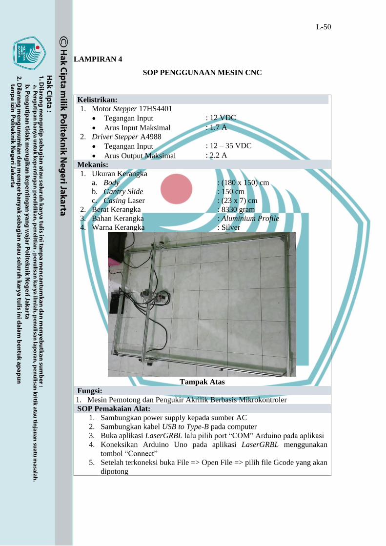
L-50
LAMPIRAN 4
SOP PENGGUNAAN MESIN CNC
Kelistrikan:
1. Motor Stepper 17HS4401
• Tegangan Input : 12 VDC
• Arus Input Maksimal : 1.7 A
2. Driver Stepper A4988
• Tegangan Input : 12 – 35 VDC
• Arus Output Maksimal : 2.2 A
Mekanis:
1. Ukuran Kerangka
a. Body
b. Gantry Slide
c. Casing Laser
: (180 x 150) cm
: 150 cm
: (23 x 7) cm
2. Berat Kerangka : 8330 gram
3. Bahan Kerangka : Aluminium Profile
4. Warna Kerangka : Silver
Tampak Atas
Fungsi:
1. Mesin Pemotong dan Pengukir Akrilik Berbasis Mikrokontroler
SOP Pemakaian Alat:
1. Sambungkan power supply kepada sumber AC
2. Sambungkan kabel USB to Type-B pada computer
3. Buka aplikasi LaserGRBL lalu pilih port “COM” Arduino pada aplikasi
4. Koneksikan Arduino Uno pada aplikasi LaserGRBL menggunakan
tombol “Connect”
5. Setelah terkoneksi buka File => Open File => pilih file Gcode yang akan
dipotong

L-51
6. Setelah itu atur kecepatan potong, set point zero, daya laser, dan jumlah
cycle potong
7. Klik tombol start lalu tunggu mesin memotong material
8. Setelah selesai mesin memotong maka laser akan Kembali ke point zero
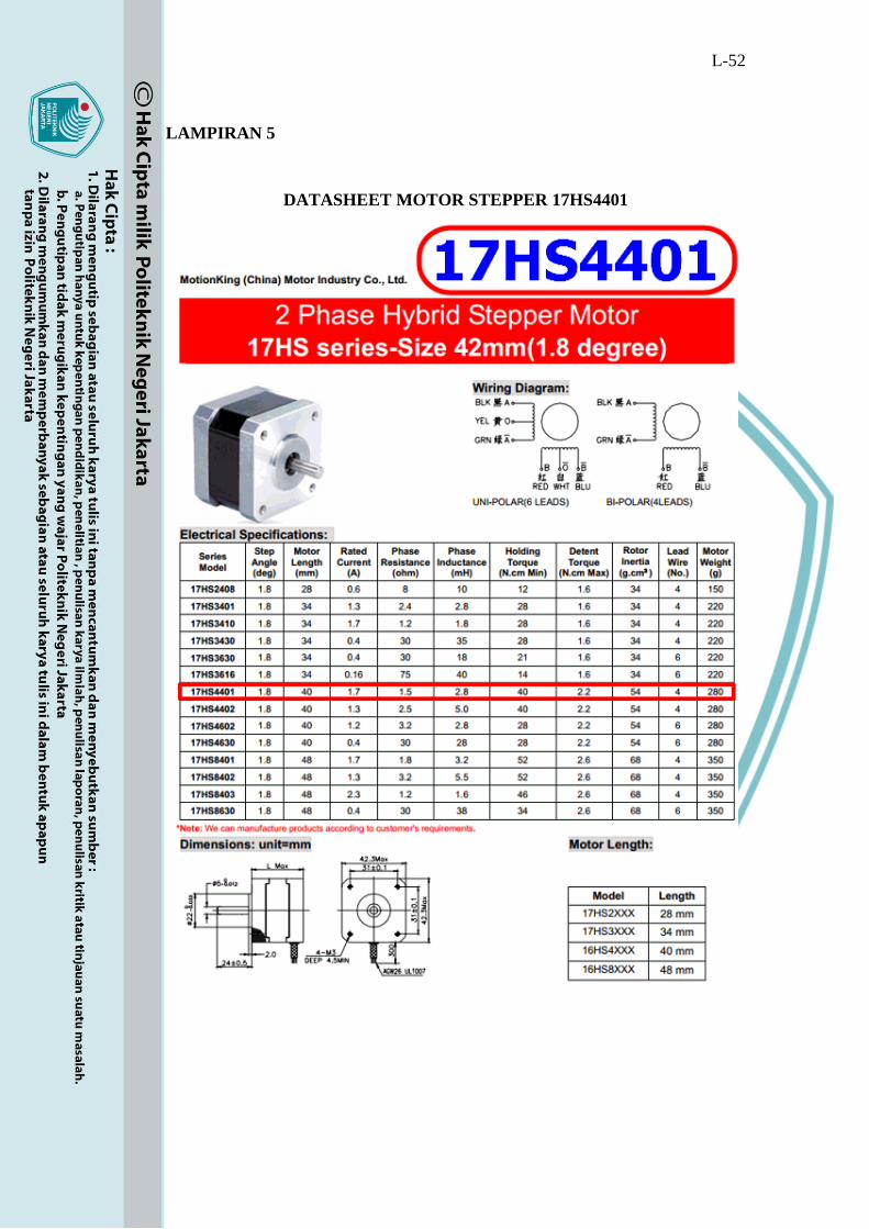
L-52
LAMPIRAN 5
DATASHEET MOTOR STEPPER 17HS4401
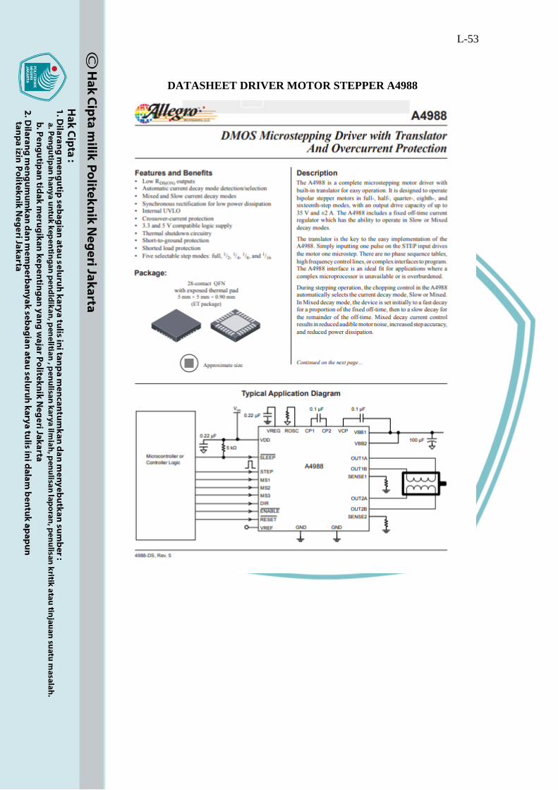
L-53
DATASHEET DRIVER MOTOR STEPPER A4988
Related Documents