(revised 4/27/01) RAMSAUER - TOWNSEND EFFECT Advanced Laboratory, Physics 407, University of Wisconsin Madison, Wisconsin 53706 Abstract The scattering cross section of electrons on noble gas atoms ex- hibits a very small value at electron energies near 1 eV. This is the Ramsauer-Townsend effect and provides an example of a phenomenon which requires a quantum mechanical description of the interaction of particles. 1

Welcome message from author
This document is posted to help you gain knowledge. Please leave a comment to let me know what you think about it! Share it to your friends and learn new things together.
Transcript
(revised 4/27/01)
RAMSAUER - TOWNSEND EFFECT
Advanced Laboratory, Physics 407,University of Wisconsin
Madison, Wisconsin 53706
Abstract
The scattering cross section of electrons on noble gas atoms ex-hibits a very small value at electron energies near 1 eV. This is theRamsauer-Townsend effect and provides an example of a phenomenonwhich requires a quantum mechanical description of the interaction ofparticles.
1
References
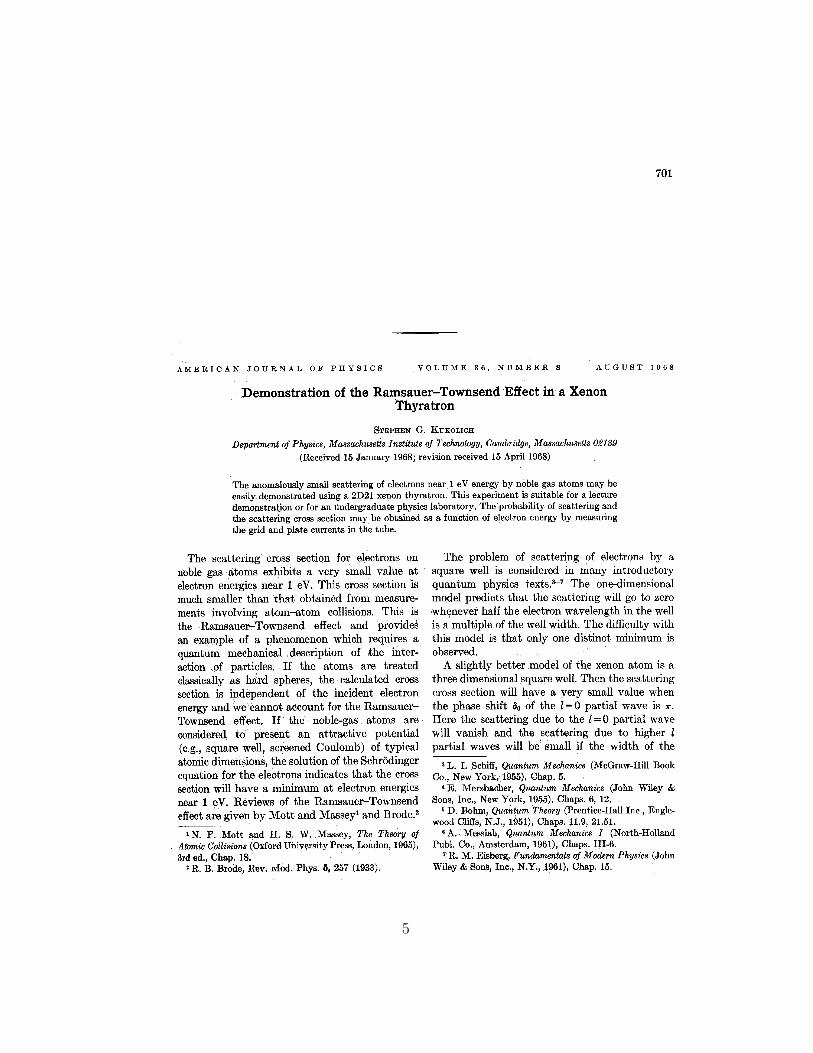
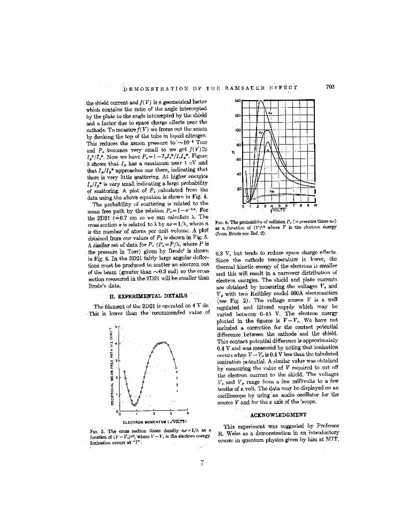
1. “Demonstration of the Ramsauer - Townsend Effect in a Xenon Thyra-tron”, S.G. Kukolich, Am. Jo. Phys. 36, 1968, pages 701 - 701,included in this description.
2. “Quantum Mechanics”, Merzbacher (Wiley), page 105.
3. “Quantum Physics”, Eisberg & Resnick (Wiley), pages 219 and prob-lem #16 on page 247.
4. “Modern Physics and Quantum Mechanics”, Anderson (Saunders), page401.
5. “The Quantitative Study of the Collisions of Electrons with Atoms”,R.B. Brode, Rev. Mod. Phys., 5, (1933), pages 257 - 279.
Theory
We omit the theory here but strongly recommend that you read reference4 (start on page 396). If you understand only a little quantum mechanics,then you may profit more by reading a simplified one-dimensional treatmentin either reference 2 or reference 3.
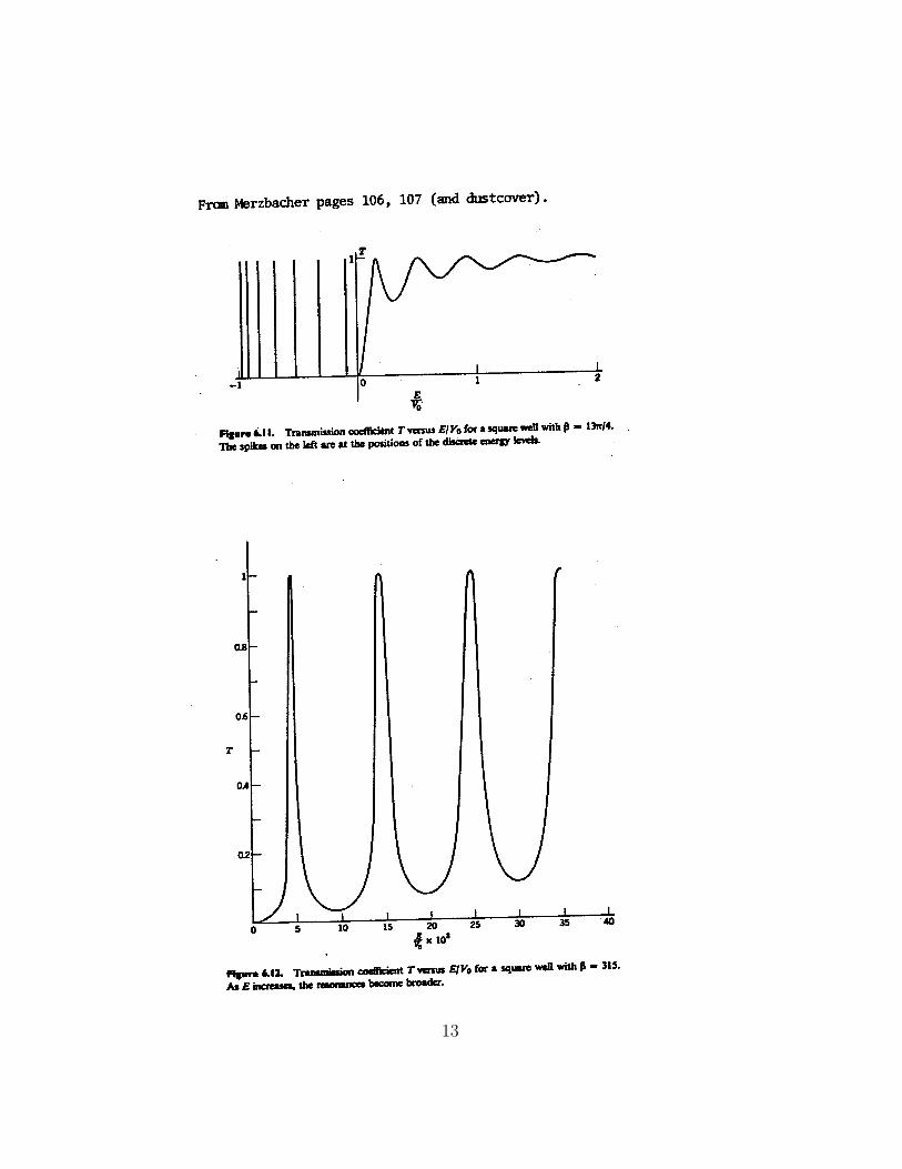
Note that reference 2 produces the interesting graph of the transmissioncoefficient which is displayed on its dust cover.
Apparatus
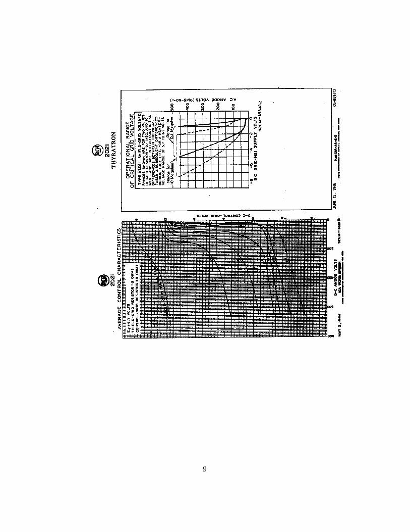
0.1 Thyratron - (RCA 2D21)
The tube contains Xenon gas. The assembly is mounted on a stand so thatthe filament of the tube is uppermost and so that the tube may be dippedinto a liquid nitrogen dewar. (Note that the voltages being used here areNOT the voltages which are normally used in thyratron circuits).
2

0.2 Regulated DC Power Supply - (Heathkit IP-27)
This provides the voltage to accelerate the electrons. The supply provides 0to 30 volts but is difficult to adjust near zero. For this reason a potentiometeris used to obtain the lowest voltages.
0.3 4-Volt Transformer
This provides the power for the thyratron filament. The tube normally uses6.3 volts AC but by running the cathode at a lower temperature the spreadin electron energies is reduced.
0.4 Dewar Flask
This will hold the liquid nitrogen necessary for freezing out the Xenon in thethyratron tube.
0.5 Digital Multimeters - (3 1/2 digit Data Precision1450)
These are high impedance meters used to measure the plate voltage, Vp; theshield voltage, Vs; and the cathode to shield voltage, (V − Vs).
3

Circuit Diagram
Thratron Socket Wiring Color Code
Pin Internal Connection Color of Wire1 grid #1 green*2 cathode black3 heater red4 heater red5 shield (grid #2) no connection6 anode yellow7 shield (grid #2) green*
* grid #1 and shield (grid #2) are joined externally
4
5
6
7

8
9

Procedure
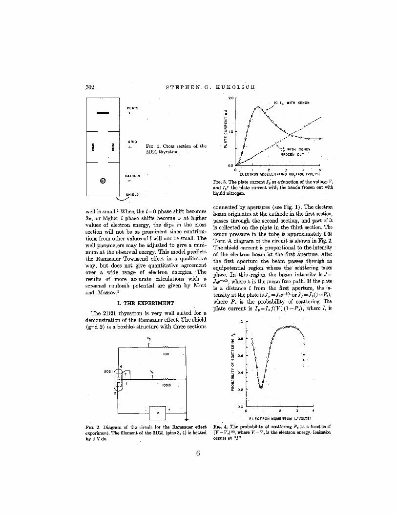
1. Read the article by S.G. Kukolich in the Am. Jour. Phys. 36, 1968,pages 701 - 703.
2. Set up the circuit as in the diagram on page 4.
3. Allow 5 minutes for the tube filament, cathode and multimeters to heatup and become stable.
4. Measure the voltages Vs and Vp as a function of the cathode to shieldvoltage (V − Vs) with the thyratron at room temperature. Try usingvalues of (V − Vs) as follows:
from 0.25 to 0.40 volts in steps of 0.025 volts0.40 to 1.00 volts in steps of 0.05 volts1.00 to 2.00 volts in steps of 0.1 volts2.00 to 3.00 volts in steps of 0.2 volts3.00 to 5.00 volts in steps of 0.5 volts5.00 to 13.00 volts in steps of 1.0 volts
The purpose of the of the uneven steps is to give the best detail between0.3 and 1.0 on the plot of
√V − Vs. You will find that you cannot
increase (V −Vs) to 13V because the Xenon gas begins to ionize. Do notincrease Vs above 3V. Estimate the voltage at which ionization occursand compare with the accepted value of 12.13 Volts. The difference isdue to the contact potential difference between cathode and shield.
5. Turn off the filament and gently immerse only the lower blackened partof the thyratron in liquid nitrogen. Allow it to cool for 15 minutes thenturn on the filament again and allow a further 5 minutes for temper-atures to stabilize. The Xenon will have condensed and frozen at thecold end of the tube.
6. Repeat measurements of Step 4 above at the same values of (V − Vs)to obtain V ∗
s and V ∗p . Adjust the tube from time to time to keep the
lower end in the liquid nitrogen.
7. Plot Ip and I∗p against√
V − Vs.
10
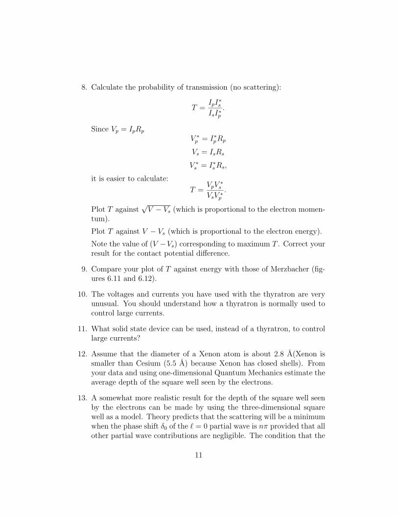
8. Calculate the probability of transmission (no scattering):
T =IpI
∗s
IsI∗p.
Since Vp = IpRp
V ∗p = I∗pRp
Vs = IsRs
V ∗s = I∗s Rs,
it is easier to calculate:
T =VpV
∗s
VsV ∗p
.
Plot T against√
V − Vs (which is proportional to the electron momen-tum).
Plot T against V − Vs (which is proportional to the electron energy).
Note the value of (V −Vs) corresponding to maximum T . Correct yourresult for the contact potential difference.
9. Compare your plot of T against energy with those of Merzbacher (fig-ures 6.11 and 6.12).
10. The voltages and currents you have used with the thyratron are veryunusual. You should understand how a thyratron is normally used tocontrol large currents.
11. What solid state device can be used, instead of a thyratron, to controllarge currents?
12. Assume that the diameter of a Xenon atom is about 2.8 A(Xenon issmaller than Cesium (5.5 A) because Xenon has closed shells). Fromyour data and using one-dimensional Quantum Mechanics estimate theaverage depth of the square well seen by the electrons.
13. A somewhat more realistic result for the depth of the square well seenby the electrons can be made by using the three-dimensional squarewell as a model. Theory predicts that the scattering will be a minimumwhen the phase shift δ0 of the ` = 0 partial wave is nπ provided that allother partial wave contributions are negligible. The condition that the
11

wave function and its derivative must be continuous at the boundaryr = a then becomes
k2a tan k1a = k1a tan k2a
where k = 2πλ
, λ1 = wave length of the electron inside the square well,and λ2 = wave length of the free electron. Use this relation to makeanother estimate of the depth of the square well.
12
13
Related Documents
![Observations of the Ramsauer–Townsend effect in quaternionic quantum ... · the important problems in quantum mechanics that has been mentioned in many quantum physics books [1–6].](https://static.cupdf.com/doc/110x72/5e2c4f600e16a47010402542/observations-of-the-ramsaueratownsend-effect-in-quaternionic-quantum-the-important.jpg)