ATDI Propagation Models in ICS telecom

Radio Propagation Webinar
Dec 27, 2015
radio
Welcome message from author
This document is posted to help you gain knowledge. Please leave a comment to let me know what you think about it! Share it to your friends and learn new things together.
Transcript
ATDI Propagation Models in
ICS telecom
Webinar aim: identify which radio propagation models
are implemented in ICS telecom
Including:• Propagation model limitations• Clutter settings• What calculations take place• Identifying the most appropriate model• Examining the useful / popular radio propagation modelsnb. Due to time constraints the lesser known radio propagation models including corrections such as rain, gas and reflections will not be covered.
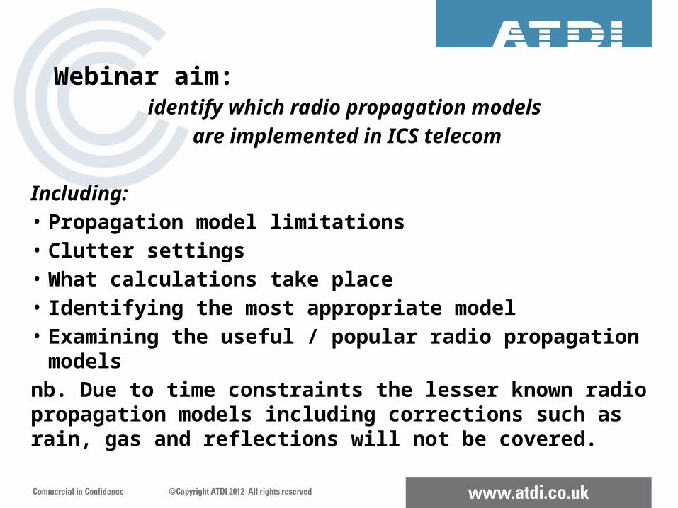
Webinar aim: present propagation models in a
similar form to ITU-R P.1144-5
Method Application Type Output Frequency Distance % time % location Terminal height
Input data ATDI implementation
& commentsName of Method in ICS Telecom
Where the application is used eg. Broadcast, areonautical etc
Point-to-point or point to area
Field strength, pathloss
Valid frequency range of operation
Valid distance(s)
% time factored into calculation
% locations factored into calculation
Valid range of terminal heights
Data required to operate the propagation calculation
Comments on implementation in ICS Telecom
A guide to radio propagation models in ICS telecomwill be published shortly.
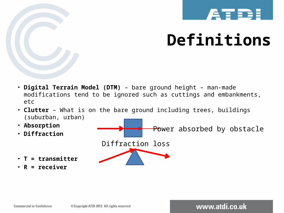
Definitions
• Digital Terrain Model (DTM) – bare ground height – man-made modifications tend to be ignored such as cuttings and embankments, etc
• Clutter – What is on the bare ground including trees, buildings (suburban, urban)• Absorption• Diffraction
• T = transmitter• R = receiver
Power absorbed by obstacle
Diffraction loss
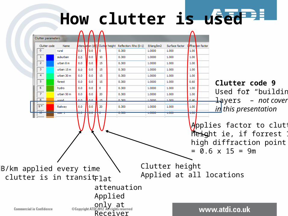
How clutter is used
dB/km applied every time clutter is in transit Flat attenuation
Applied only at Receiver pixel
Clutter heightApplied at all locations
Applies factor to clutterheight ie, if forrest 15m high diffraction point= 0.6 x 15 = 9m
Clutter code 9Used for “buildinglayers” – not coveredin this presentation
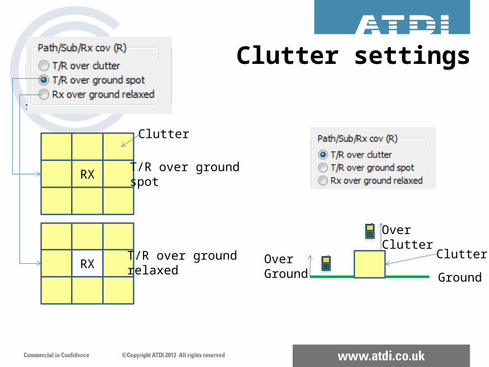
RX T/R over ground spot
RXT/R over ground relaxed
Clutter
GroundOverGround
OverClutter
Clutter
Clutter settings
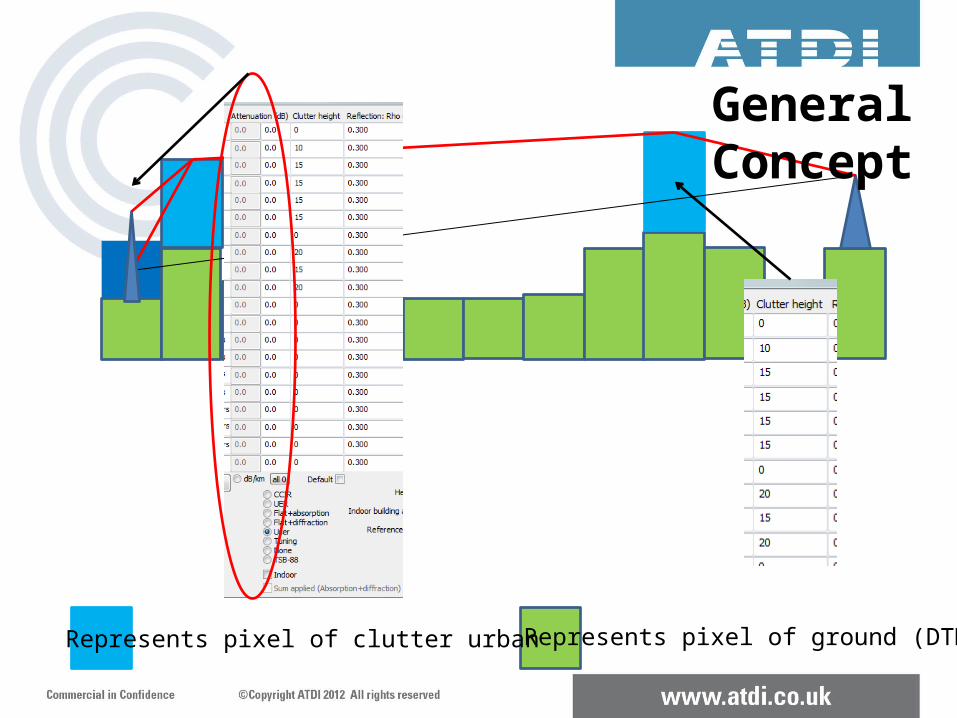
Represents pixel of ground (DTM)Represents pixel of clutter urban
General Concept
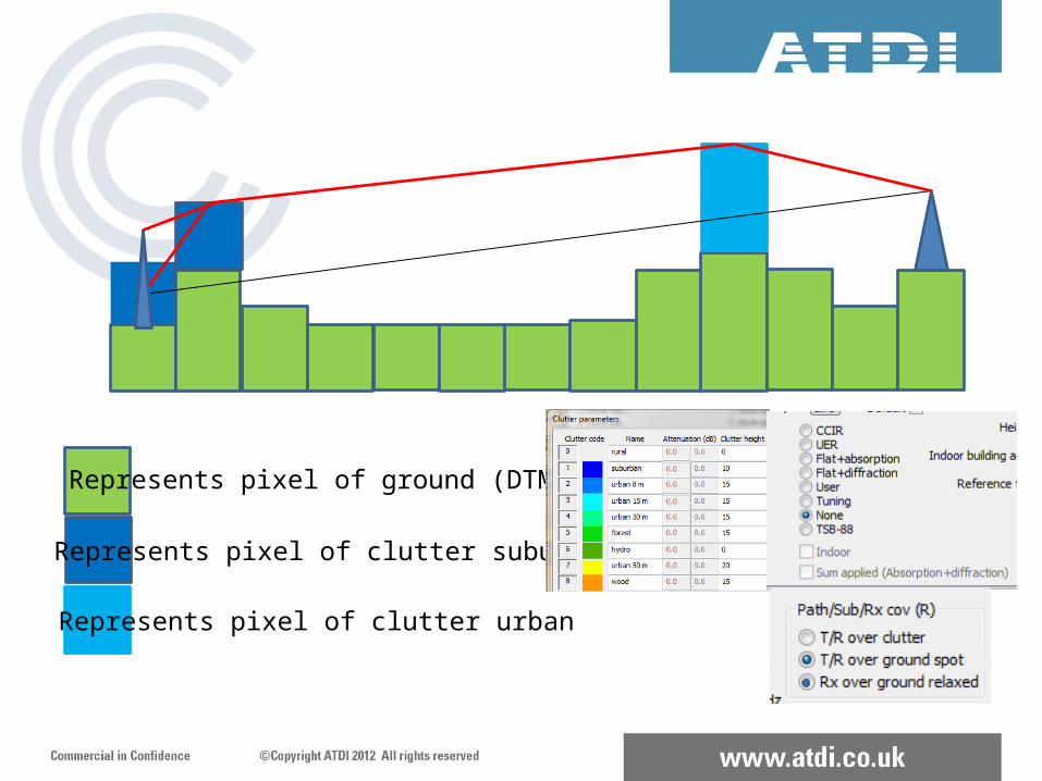
Represents pixel of ground (DTM)
Represents pixel of clutter suburban
Represents pixel of clutter urban
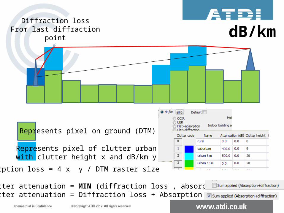
Represents pixel on ground (DTM)
Represents pixel of clutter urban with clutter height x and dB/km y
Absorption loss = 4 x y / DTM raster size
Clutter attenuation = MIN (diffraction loss , absorption loss) Clutter attenuation = Diffraction loss + Absorption loss
Diffraction lossFrom last diffraction
point dB/km
Diffraction lossfrom last diffractionpoint
Flat attenuation
A
B
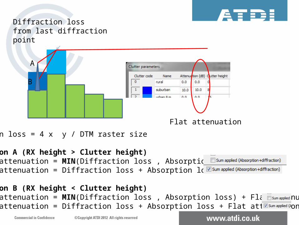
Absorption loss = 4 x y / DTM raster size
At Location A (RX height > Clutter height) Clutter attenuation = MIN(Diffraction loss , Absorption loss) Clutter attenuation = Diffraction loss + Absorption loss
At Location B (RX height < Clutter height) Clutter attenuation = MIN(Diffraction loss , Absorption loss) + Flat attenuation Clutter attenuation = Diffraction loss + Absorption loss + Flat attenuation
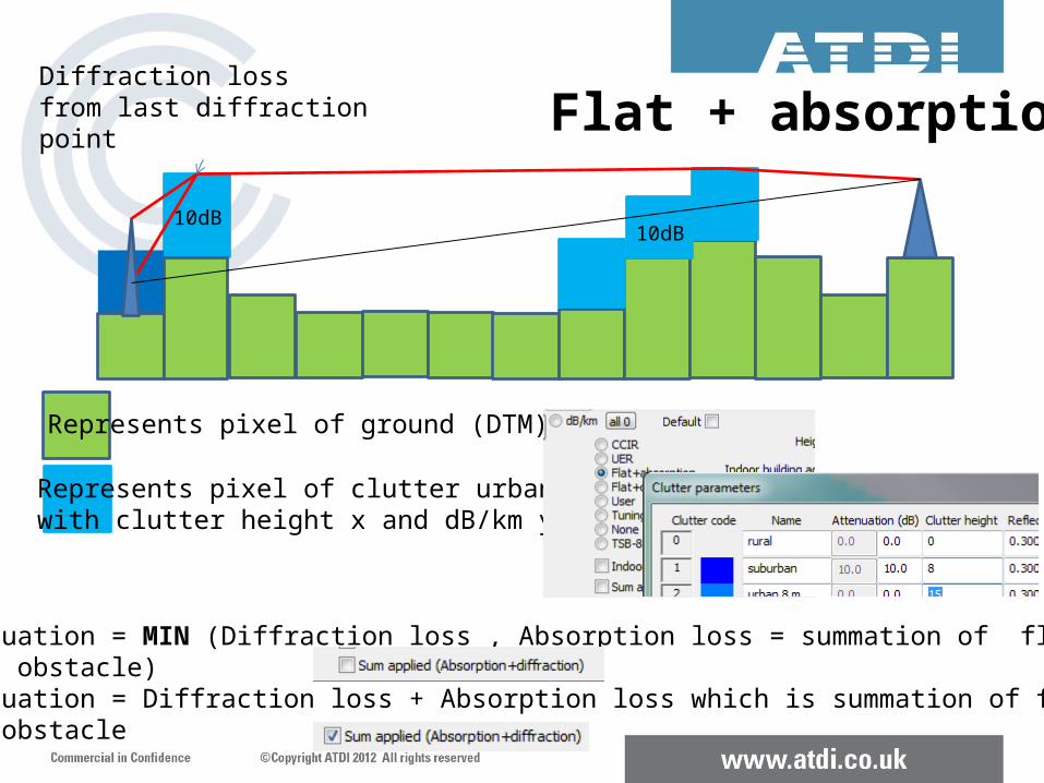
Represents pixel of ground (DTM)
Represents pixel of clutter urban with clutter height x and dB/km y
Clutter attenuation = MIN (Diffraction loss , Absorption loss = summation of flat loss for each separate obstacle) Clutter attenuation = Diffraction loss + Absorption loss which is summation of flat loss for Each separate obstacle
Diffraction lossfrom last diffractionpoint
Flat + absorption
10dB10dB
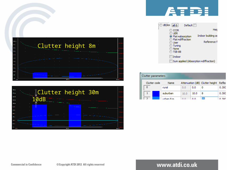
Clutter height 8m
Clutter height 30m10dB
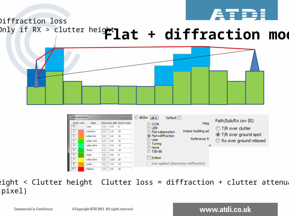
Flat + diffraction modeDiffraction lossOnly if RX > clutter height
If RX height < Clutter height Clutter loss = diffraction + clutter attenuations into RX pixel)
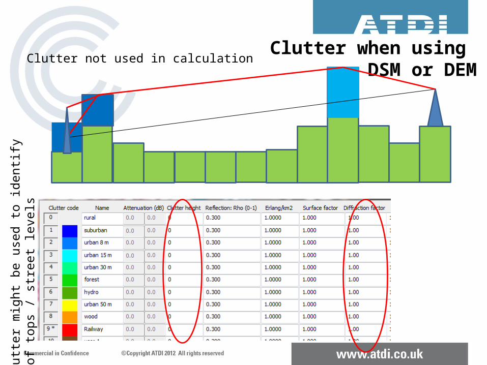
Clutter when using DSM or DEM
Clutter not used in calculation
Clutt
er m
ight
be
used
to id
entif
y Ro
of to
ps /
stre
et le
vels
Peter Paul
Nick you need to define what these are, this is the first time you have used them in the slideshow
• CCIR and UER are similar to flat + diffraction, except with standard values for mobiles (CCIR) and TV reception (UER)
• TSB-88 Mode (NTIA report TSB-88-B similar to flat + diffraction except clutter attenuation need to change with frequency (clutter height should be set to zero)
• USER same as flat + diffraction except where RX height > clutter height in which case it is diffraction + flat attenuation into last pixel
Clutter code 9 has a specific role and is used as identification for building layer
Building layers are not covered in this webinar
Demonstrate best way to test clutter settings and attenuations.
DEMO
Other Clutter modes
Radio Propagation Models
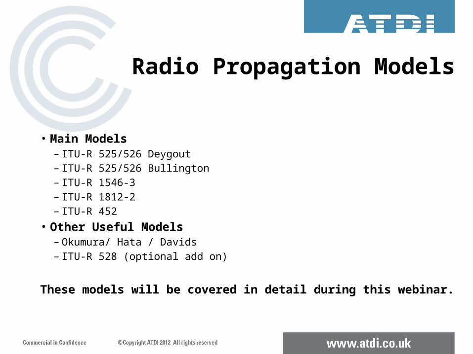
• Main Models– ITU-R 525/526 Deygout– ITU-R 525/526 Bullington– ITU-R 1546-3– ITU-R 1812-2– ITU-R 452
• Other Useful Models– Okumura/ Hata / Davids– ITU-R 528 (optional add on)
These models will be covered in detail during this webinar.
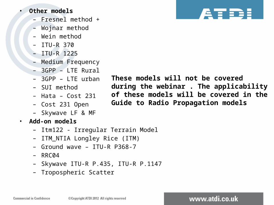
• Other models– Fresnel method +– Wojnar method– Wein method– ITU-R 370– ITU-R 1225– Medium Frequency– 3GPP – LTE Rural– 3GPP – LTE urban– SUI method– Hata – Cost 231– Cost 231 Open– Skywave LF & MF
• Add-on models– Itm122 - Irregular Terrain Model– ITM_NTIA Longley Rice (ITM)– Ground wave – ITU-R P368-7– RRC04– Skywave ITU-R P.435, ITU-R P.1147– Tropospheric Scatter
These models will not be covered during the webinar . The applicabilityof these models will be covered in theGuide to Radio Propagation models
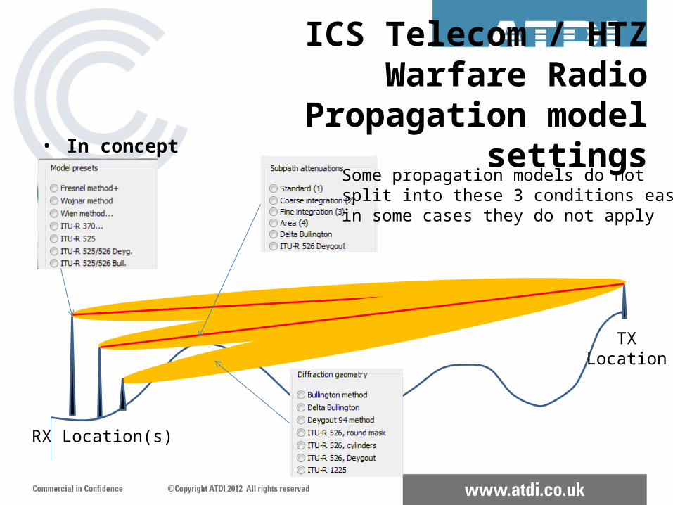
ICS Telecom / HTZ Warfare Radio Propagation model settings
• In conceptSome propagation models do not split into these 3 conditions easily;in some cases they do not apply
TXLocation
RX Location(s)
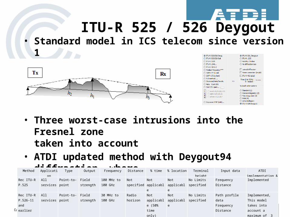
ITU-R 525 / 526 Deygout• Standard model in ICS telecom since version 1
• Three worst-case intrusions into the Fresnel zone taken into account
• ATDI updated method with Deygout94 diffraction wheremultiple intrusions are taken into account
• The ITU have now updated methodMethod Application Type Output Frequency Distance % time % location Terminal height Input data ATDI implementation &
comments
Rec ITU-R P.525 All services Point-to-point Field strength 100 MHz to 100 GHz
Not specified Not applicable
Not applicable
No Limits specified Frequency Distance
Implemented
Rec ITU-R P.526-11 and earlier
All services Point-to-point Field strength 30 MHz to 100 GHz
Radio horizon
Not applicable (50% time only)
Not applicable
No Limits specified Path profile dataFrequencyDistance
Implemented, This model takes into account a maximum of 3 intrusions into the Fresnel zone and is a Dygout model
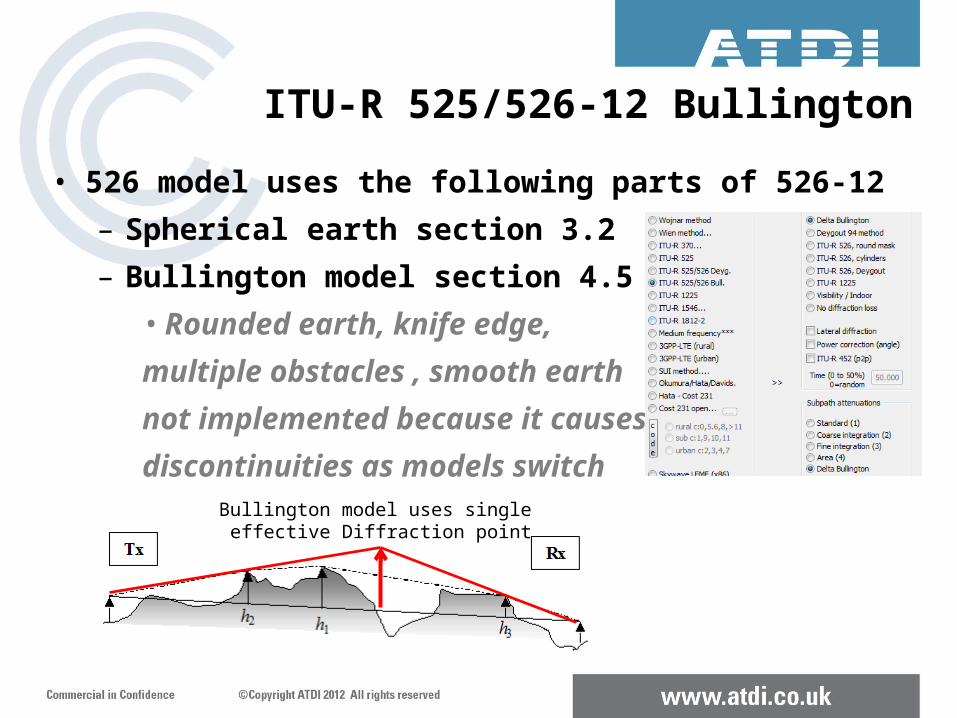
ITU-R 525/526-12 Bullington• 526 model uses the following parts of 526-12
– Spherical earth section 3.2– Bullington model section 4.5
• Rounded earth, knife edge, multiple obstacles , smooth earth not implemented because it causes discontinuities as models switch
Bullington model uses single effective Diffraction point
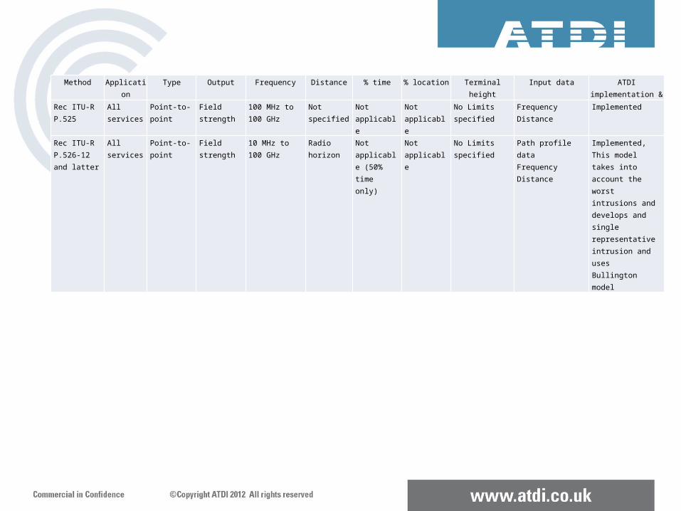
Method Application Type Output Frequency Distance % time % location Terminal height Input data ATDI implementation & comments
Rec ITU-R P.525 All services Point-to-point Field strength 100 MHz to 100 GHz
Not specified Not applicable
Not applicable
No Limits specified Frequency Distance
Implemented
Rec ITU-R P.526-12 and latter
All services Point-to-point Field strength 10 MHz to 100 GHz
Radio horizon
Not applicable (50% time only)
Not applicable
No Limits specified Path profile dataFrequencyDistance
Implemented, This model takes into account the worst intrusions and develops and single representative intrusion and uses Bullington model
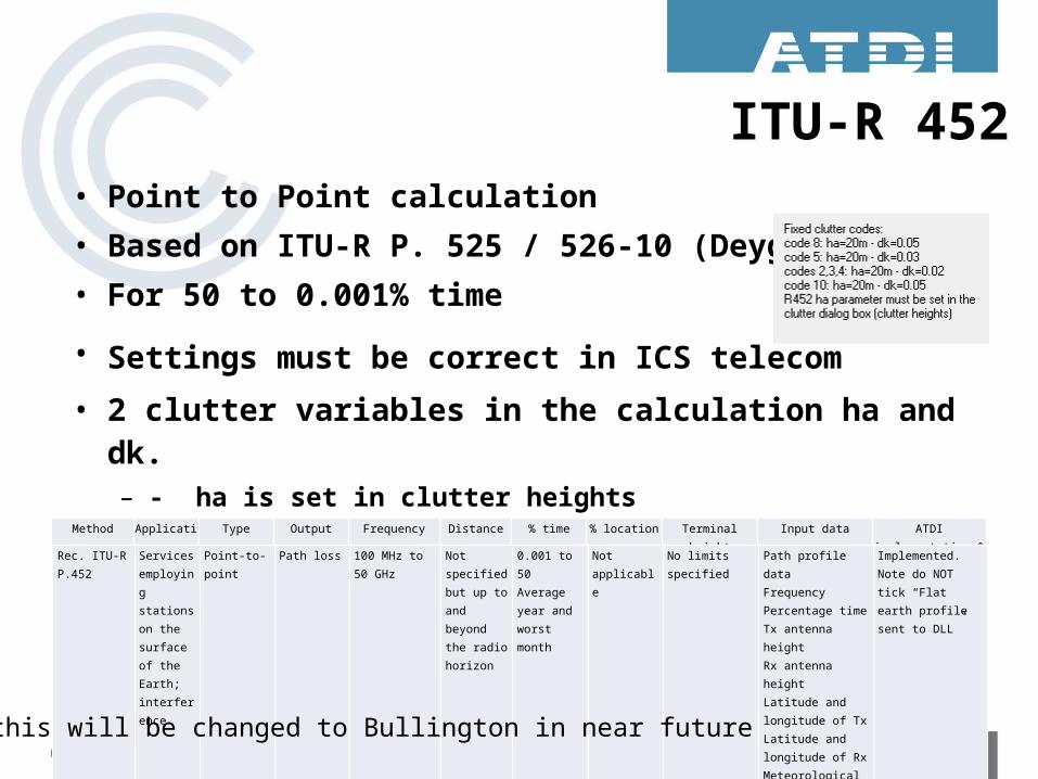
ITU-R 452• Point to Point calculation• Based on ITU-R P. 525 / 526-10 (Deygout)**• For 50 to 0.001% time
• Settings must be correct in ICS telecom • 2 clutter variables in the calculation ha and dk.
– - ha is set in clutter heights – dk value applied is based on clutter code
Method Application Type Output Frequency Distance % time % location Terminal height Input data ATDI implementation & comments
Rec. ITU-R P.452
Services employing stations on the surface of the Earth; interference
Point-to-point Path loss 100 MHz to 50 GHz
Not specified but up to and beyond the radio horizon
0.001 to 50Average year and worst month
Not applicable
No limits specified Path profile dataFrequencyPercentage timeTx antenna heightRx antenna heightLatitude and longitude of TxLatitude and longitude of Rx Meteorological data
Implemented. Note do NOT tick “Flat earth profile sent to DLL”
** Note this will be changed to Bullington in near future
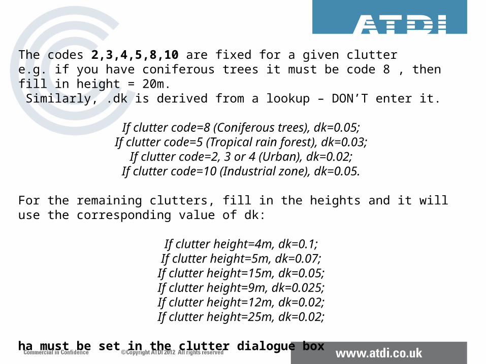
The codes 2,3,4,5,8,10 are fixed for a given clutter e.g. if you have coniferous trees it must be code 8 , then fill in height = 20m. Similarly, .dk is derived from a lookup – DON’T enter it.
If clutter code=8 (Coniferous trees), dk=0.05;If clutter code=5 (Tropical rain forest), dk=0.03;
If clutter code=2, 3 or 4 (Urban), dk=0.02;If clutter code=10 (Industrial zone), dk=0.05.
For the remaining clutters, fill in the heights and it will use the corresponding value of dk:
If clutter height=4m, dk=0.1;If clutter height=5m, dk=0.07;
If clutter height=15m, dk=0.05;If clutter height=9m, dk=0.025;If clutter height=12m, dk=0.02;If clutter height=25m, dk=0.02;
ha must be set in the clutter dialogue box
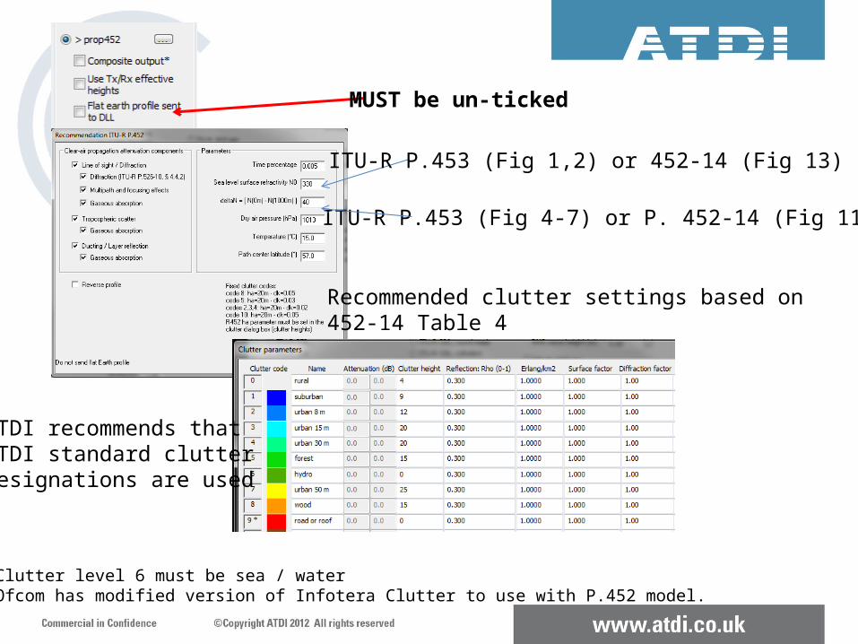
ITU-R P.453 (Fig 1,2) or 452-14 (Fig 13)
ITU-R P.453 (Fig 4-7) or P. 452-14 (Fig 11)
MUST be un-ticked
Recommended clutter settings based on 452-14 Table 4
ATDI recommends that ATDI standard clutter designations are used
Note 1: Clutter level 6 must be sea / waterNote 2: Ofcom has modified version of Infotera Clutter to use with P.452 model.
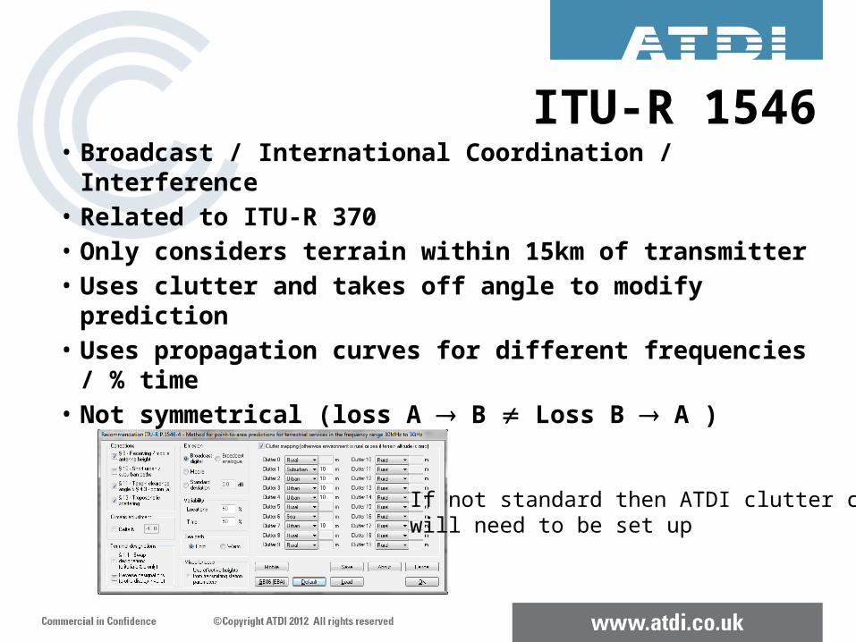
ITU-R 1546• Broadcast / International Coordination / Interference• Related to ITU-R 370• Only considers terrain within 15km of transmitter• Uses clutter and takes off angle to modify prediction• Uses propagation curves for different frequencies / %
time• Not symmetrical (loss A B Loss B A )
If not standard then ATDI clutter codeswill need to be set up
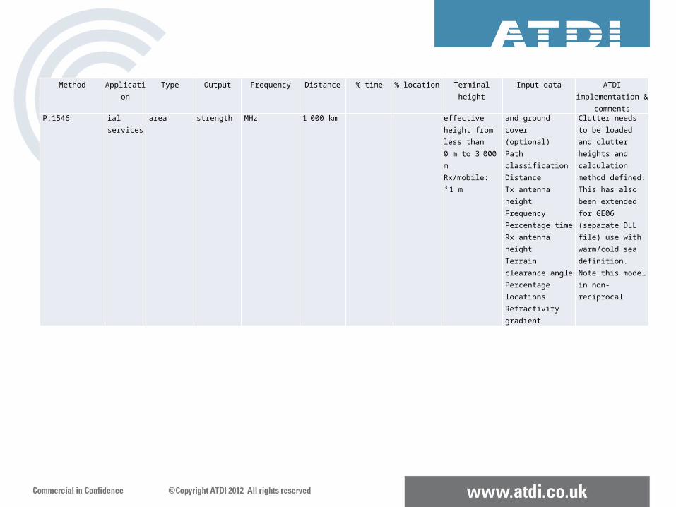
Rec. ITU-R P.1546 Terrestrial services
Point-to-area Field strength 30 to 3 000 MHz 1 to 1 000 km
1 to 50 1 to 99 Tx/base: effective height from less than 0 m to 3 000 mRx/mobile: ³ 1 m
Terrain height and ground cover (optional)Path classificationDistanceTx antenna heightFrequencyPercentage timeRx antenna heightTerrain clearance anglePercentage locationsRefractivity gradient
Implemented. Clutter needs to be loaded and clutter heights and calculation method defined. This has also been extended for GE06 (separate DLL file) use with warm/cold sea definition. Note this model in non-reciprocal
Method Application Type Output Frequency Distance % time % location Terminal height Input data ATDI implementation & comments
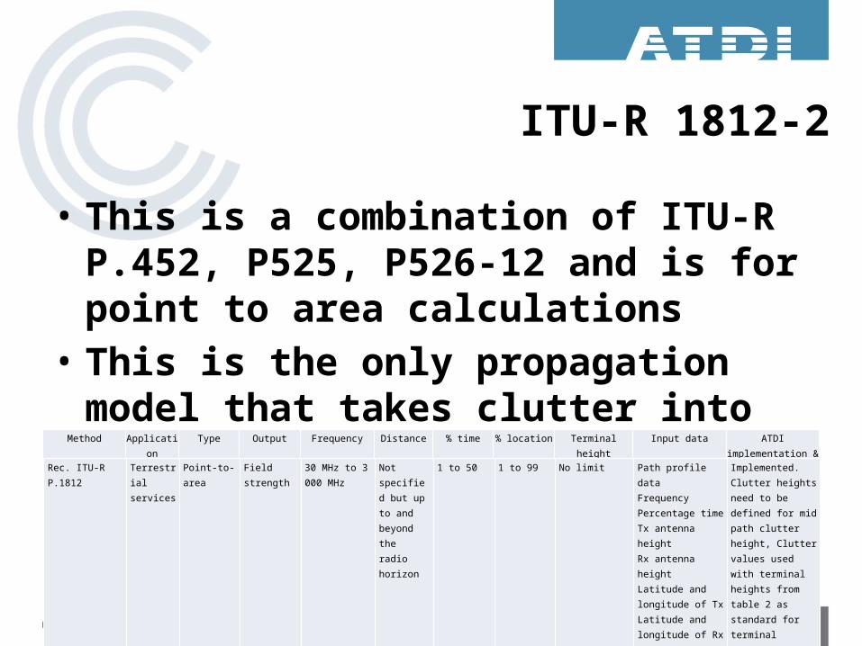
ITU-R 1812-2
• This is a combination of ITU-R P.452, P525, P526-12 and is for point to area calculations
• This is the only propagation model that takes clutter into account at both ends of the path
Method Application Type Output Frequency Distance % time % location Terminal height Input data ATDI implementation & comments
Rec. ITU-R P.1812 Terrestrial services
Point-to-area Field strength 30 MHz to 3 000 MHz
Not specified but up to and beyond the radio horizon
1 to 50 1 to 99 No limit Path profile dataFrequencyPercentage timeTx antenna heightRx antenna heightLatitude and longitude of TxLatitude and longitude of Rx Meteorological data
Implemented. Clutter heights need to be defined for mid path clutter height, Clutter values used with terminal heights from table 2 as standard for terminal clutter losses
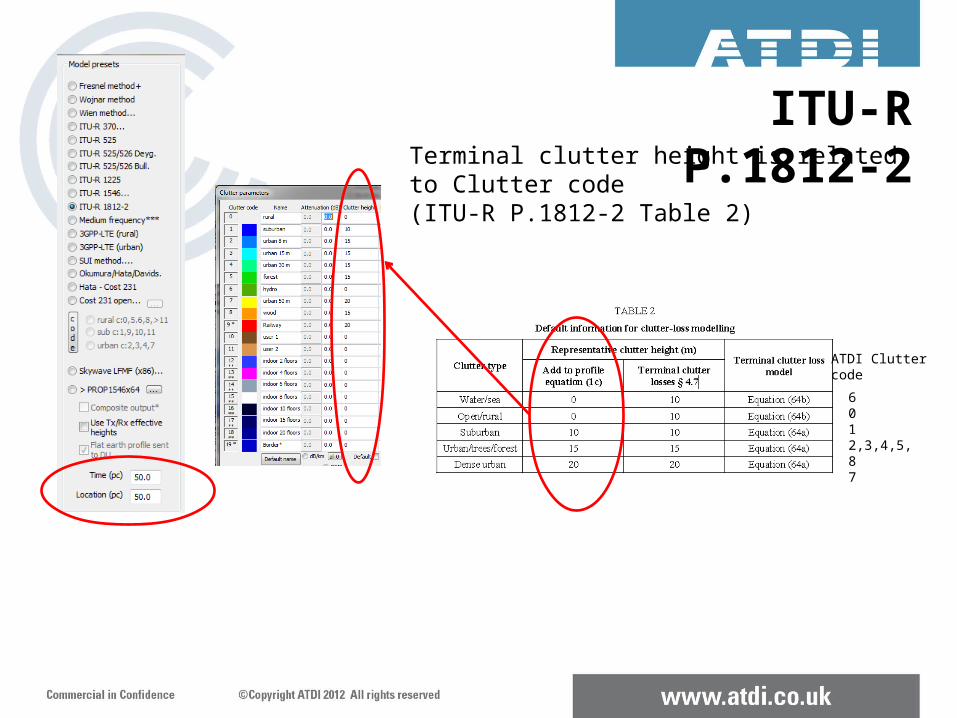
Terminal clutter height is relatedto Clutter code (ITU-R P.1812-2 Table 2)
6012,3,4,5,87
ATDI Cluttercode
ITU-R P.1812-2
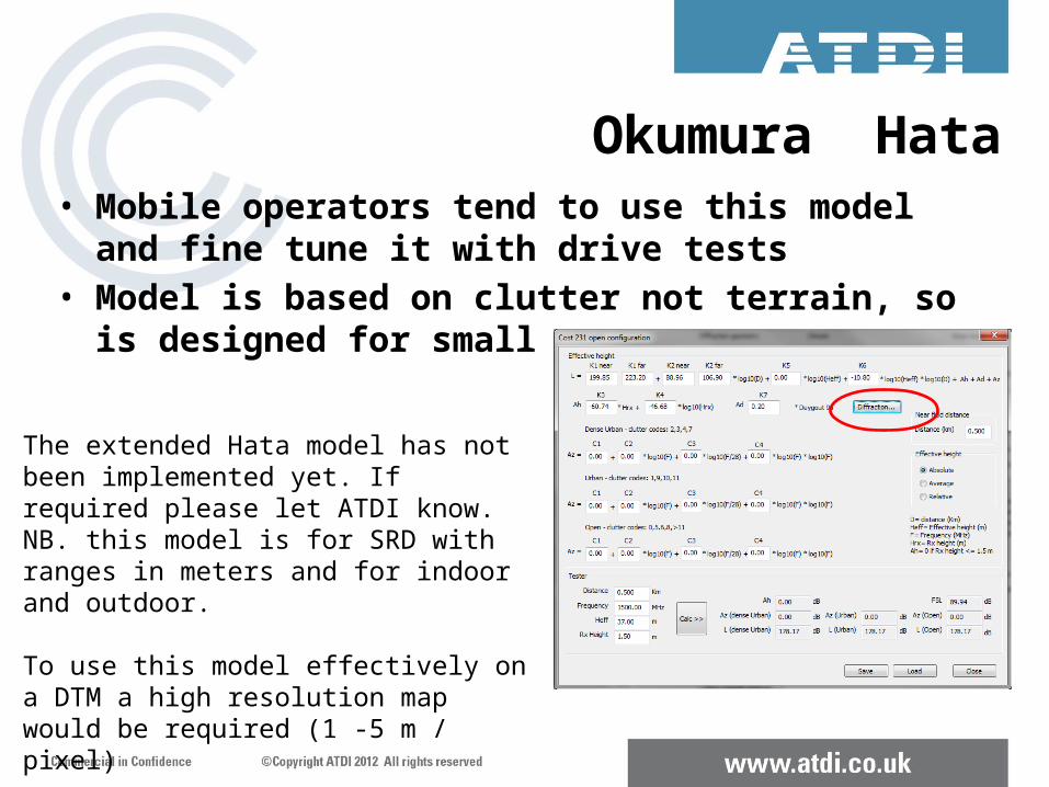
Okumura Hata• Mobile operators tend to use this model and fine tune it
with drive tests• Model is based on clutter not terrain, so is designed for small
ranges
The extended Hata model has not been implemented yet. If required please let ATDI know. NB. this model is for SRD with ranges in meters and for indoor and outdoor.
To use this model effectively on a DTM a high resolution map would be required (1 -5 m / pixel)
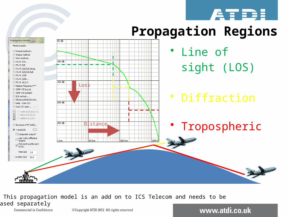
• Line of sight (LOS)
• Diffraction
• Tropospheric
Loss
Distance
Propagation Regions
Note: This propagation model is an add on to ICS Telecom and needs to be Purchased separately
Other Corrections to Propagation Models
• Rain - World based on ITU-R P.538 and UK rain on Ofcom data
• Snow – Isotherm level (level at which water freezes) if path passes though this level this correction is applied
• Fog – ITU-R 840
• Gas – ITU-R 676 (Note ITU-R F.1820 is Gas attenuation from HAP at 47GHz)
• Wave height - (applies an effective clutter height depending on wind strength)
• Reflections
Comparison of Radio Propagation models in ICS telecom
DEMO

Thank you for attending todayAny questions?
ATDI LimitedThe Beehive – City Place – Gatwick
West Sussex – RH6 0PA – UK
Tel +44 (0)1293 522052 - Fax +44 (0)1293 522521
Email: [email protected]
Related Documents