RE 15300/08.2019, Bosch Rexroth AB Valid for: ▶ Torque range: up to 1970 kNm [up to 1452717 lb-ft] ▶ Speed:range: up to 70 rpm ▶ Power range: up to 2393 kW ▶ Maximum operating pressure: 350 bar [5076 psi] ▶ Frame size: 2000, 3000, 4000, 5000 and 6000 ▶ Displacement: 63108 to 380178 cm3/rev [3851 to 23200 in3/rev] ▶ Specific torque: 1000 to 6 000 Nm/bar [50 853 to 305 119 ft-lbs/1000 psi] Features ▶ High power density ▶ High torque density ▶ Energy efficient ▶ Flexible, many sizes, few mechanical interfaces. ▶ Insensitive for shock loads ▶ Very low moment of inertia ▶ Small footprint (total occupied volume) ▶ Freewheeling possibility ▶ Through hole diameter 270 mm ▶ Tandem mounting possibilty ▶ Version with shrink disc coupling available for CBM 2000 to CBM 3000, which gives direct and easy retrofit for Hägglunds MB 1600 and MB 2400 motors Contents 1 Ordering code ....................................................... 2 2 Functional description .......................................... 4 3 Fluid connections .................................................. 5 4 Technical data ....................................................... 7 5 Type of seal ......................................................... 45 6 Increased robustness .......................................... 45 7 Through hole kit .................................................. 46 8 Dimensions / Interface ........................................ 47 9 Mounting alternatives .......................................... 52 10 Accessories ......................................................... 58 11 Circuit design ...................................................... 70 12 Related documents ............................................. 72 Radial Piston Hydraulic motor Hägglunds CBm RE 15300/08.2019 Replaces: 06.2018

Welcome message from author
This document is posted to help you gain knowledge. Please leave a comment to let me know what you think about it! Share it to your friends and learn new things together.
Transcript
RE 15300/08.2019, Bosch Rexroth AB
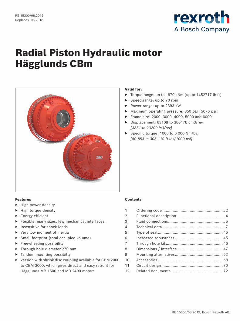
Valid for: ▶ Torque range: up to 1970 kNm [up to 1452717 lb-ft] ▶ Speed:range: up to 70 rpm ▶ Power range: up to 2393 kW ▶ Maximum operating pressure: 350 bar [5076 psi] ▶ Frame size: 2000, 3000, 4000, 5000 and 6000 ▶ Displacement: 63108 to 380178 cm3/rev
[3851 to 23200 in3/rev] ▶ Specific torque: 1000 to 6 000 Nm/bar
[50 853 to 305 119 ft-lbs/1000 psi]
Features ▶ High power density ▶ High torque density ▶ Energy efficient ▶ Flexible, many sizes, few mechanical interfaces. ▶ Insensitive for shock loads ▶ Very low moment of inertia ▶ Small footprint (total occupied volume) ▶ Freewheeling possibility ▶ Through hole diameter 270 mm ▶ Tandem mounting possibilty ▶ Version with shrink disc coupling available for CBM 2000
to CBM 3000, which gives direct and easy retrofit for Hägglunds MB 1600 and MB 2400 motors
Contents
1 Ordering code ....................................................... 22 Functional description .......................................... 43 Fluid connections .................................................. 54 Technical data ....................................................... 75 Type of seal ......................................................... 456 Increased robustness .......................................... 457 Through hole kit .................................................. 468 Dimensions / Interface ........................................ 479 Mounting alternatives .......................................... 5210 Accessories ......................................................... 5811 Circuit design ...................................................... 7012 Related documents ............................................. 72
Radial Piston Hydraulic motorHägglunds CBm
RE 15300/08.2019Replaces: 06.2018
2/72 Hägglunds CA | Radial piston hydraulic motor
Bosch Rexroth AB, RE 15300/08.2019
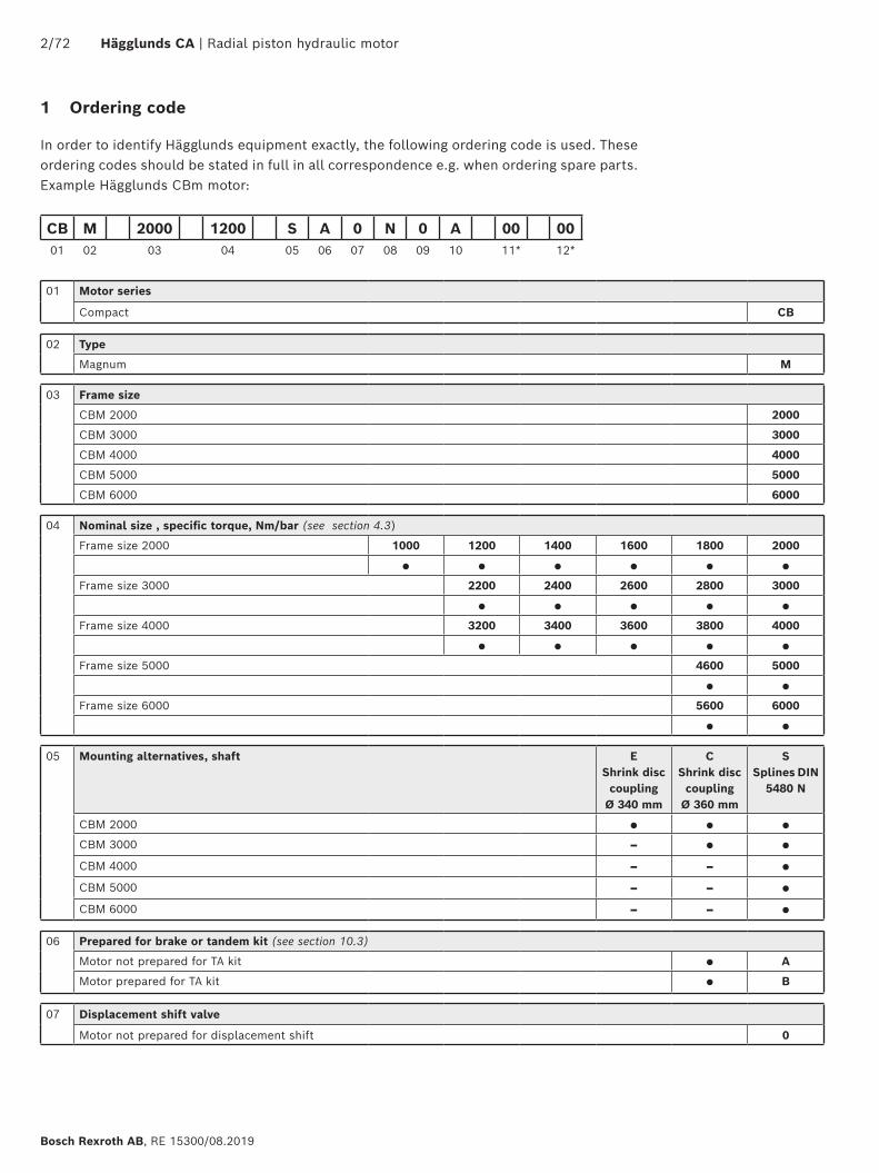
1 Ordering code
In order to identify Hägglunds equipment exactly, the following ordering code is used. These ordering codes should be stated in full in all correspondence e.g. when ordering spare parts.Example Hägglunds CBm motor:
CB M 2000 1200 S A 0 N 0 A 00 0001 02 03 04 05 06 07 08 09 10 11* 12*
01 Motor series
Compact CB
02 Type
Magnum M
03 Frame size
CBM 2000 2000
CBM 3000 3000
CBM 4000 4000
CBM 5000 5000
CBM 6000 6000
04 Nominal size , specific torque, Nm/bar (see section 4.3)
Frame size 2000 1000 1200 1400 1600 1800 2000
● ● ● ● ● ●
Frame size 3000 2200 2400 2600 2800 3000
● ● ● ● ●
Frame size 4000 3200 3400 3600 3800 4000
● ● ● ● ●
Frame size 5000 4600 5000
● ●
Frame size 6000 5600 6000
● ●
05 Mounting alternatives, shaft E Shrink disc coupling
Ø 340 mm
CShrink disc coupling
Ø 360 mm
S Splines DIN
5480 N
CBM 2000 ● ● ●
CBM 3000 – ● ●
CBM 4000 – – ●
CBM 5000 – – ●
CBM 6000 – – ●
06 Prepared for brake or tandem kit (see section 10.3)
Motor not prepared for TA kit ● A
Motor prepared for TA kit ● B
07 Displacement shift valve
Motor not prepared for displacement shift 0
Radial piston hydraulic motor | Hägglunds CA 3/72
RE 15300/08.2019, Bosch Rexroth AB
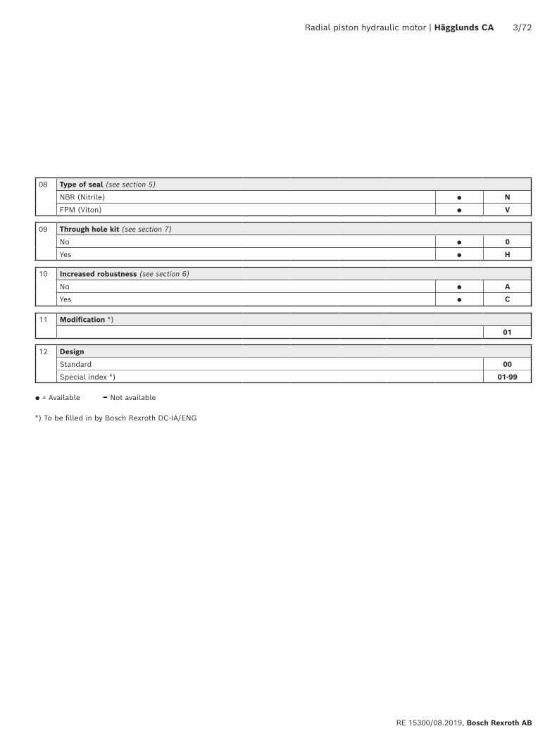
08 Type of seal (see section 5)
NBR (Nitrile) ● N
FPM (Viton) ● V
09 Through hole kit (see section 7)
No ● 0
Yes ● H
10 Increased robustness (see section 6)
No ● A
Yes ● C
11 Modification *)
01
12 Design
Standard 00
Special index *) 01-99
● = Available – Not available
*) To be filled in by Bosch Rexroth DC-IA/ENG
4/72 Hägglunds CA | Radial piston hydraulic motor
Bosch Rexroth AB, RE 15300/08.2019
1
2
3
4
5
10
9
11
7
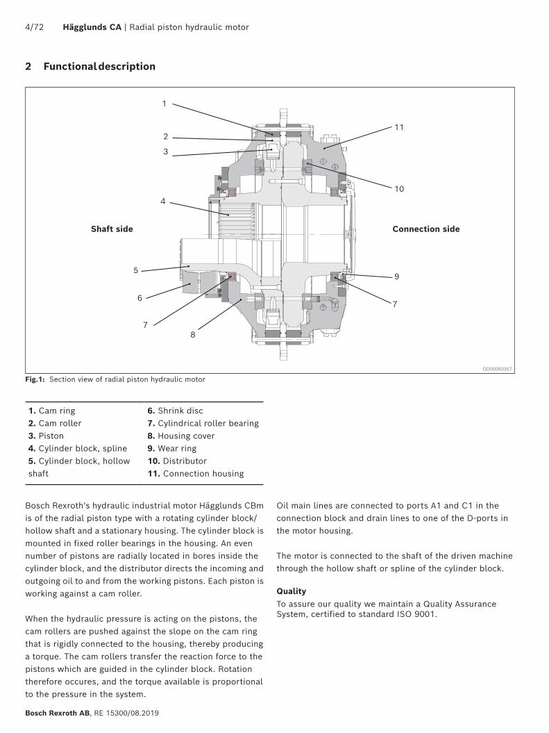
Oil main lines are connected to ports A1 and C1 in the connection block and drain lines to one of the D-ports in the motor housing.
The motor is connected to the shaft of the driven machine through the hollow shaft or spline of the cylinder block.
QualityTo assure our quality we maintain a Quality Assurance System, certified to standard ISO 9001.
Fig.1: Section view of radial piston hydraulic motorDD00093357
2 Functional description
1. Cam ring2. Cam roller3. Piston4. Cylinder block, spline5. Cylinder block, hollow shaft
6. Shrink disc7. Cylindrical roller bearing8. Housing cover 9. Wear ring10. Distributor11. Connection housing
Shaft side Connection side
6
78
Bosch Rexroth's hydraulic industrial motor Hägglunds CBm is of the radial piston type with a rotating cylinder block/hollow shaft and a stationary housing. The cylinder block is mounted in fixed roller bearings in the housing. An even number of pistons are radially located in bores inside the cylinder block, and the distributor directs the incoming and outgoing oil to and from the working pistons. Each piston is working against a cam roller.
When the hydraulic pressure is acting on the pistons, the cam rollers are pushed against the slope on the cam ring that is rigidly connected to the housing, thereby producing a torque. The cam rollers transfer the reaction force to the pistons which are guided in the cylinder block. Rotation therefore occures, and the torque available is proportional to the pressure in the system.
Radial piston hydraulic motor | Hägglunds CA 5/72
RE 15300/08.2019, Bosch Rexroth AB
3 Fluid connections
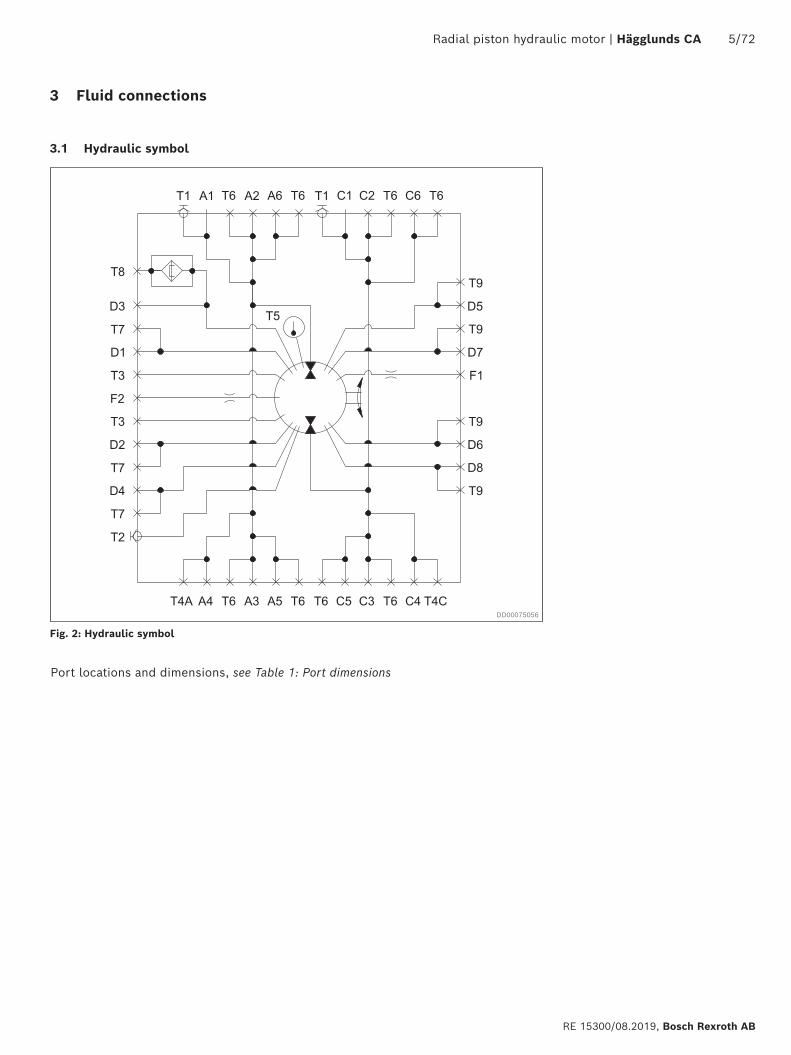
3.1 Hydraulic symbol
Fig. 2: Hydraulic symbol
DD00075056
Port locations and dimensions, see Table 1: Port dimensions
6/72 Hägglunds CA | Radial piston hydraulic motor
Bosch Rexroth AB, RE 15300/08.2019
T8 T1 D1T7T1A1
A2
T3
C1D3
C2
T6
F2
C3
A3
D4T7T4CC4A4T4AT7D2
C5
A5
T3
T6
T5
C6
A6
T2
Rotation flow inlet C1 - C6
Rotation flow inlet A1 - A6
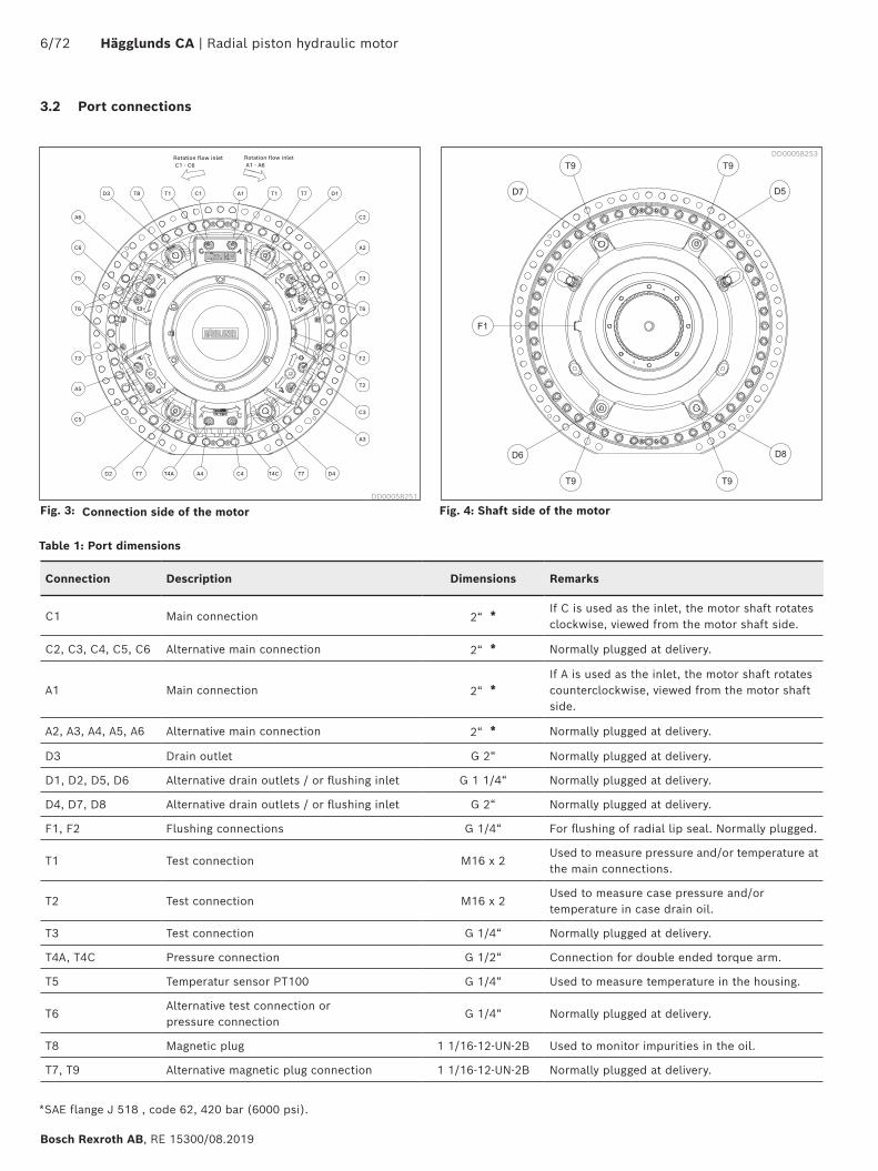
Fig. 3: Connection side of the motor Fig. 4: Shaft side of the motor
Table 1: Port dimensions
DD00058253
DD00058251
Connection Description Dimensions Remarks
C1 Main connection 2“ *If C is used as the inlet, the motor shaft rotates clockwise, viewed from the motor shaft side.
C2, C3, C4, C5, C6 Alternative main connection 2“ * Normally plugged at delivery.
A1 Main connection 2“ *If A is used as the inlet, the motor shaft rotates counterclockwise, viewed from the motor shaft side.
A2, A3, A4, A5, A6 Alternative main connection 2“ * Normally plugged at delivery.
D3 Drain outlet G 2“ Normally plugged at delivery.
D1, D2, D5, D6 Alternative drain outlets / or flushing inlet G 1 1/4“ Normally plugged at delivery.
D4, D7, D8 Alternative drain outlets / or flushing inlet G 2“ Normally plugged at delivery.
F1, F2 Flushing connections G 1/4“ For flushing of radial lip seal. Normally plugged.
T1 Test connection M16 x 2Used to measure pressure and/or temperature at the main connections.
T2 Test connection M16 x 2Used to measure case pressure and/or temperature in case drain oil.
T3 Test connection G 1/4“ Normally plugged at delivery.
T4A, T4C Pressure connection G 1/2“ Connection for double ended torque arm.
T5 Temperatur sensor PT100 G 1/4“ Used to measure temperature in the housing.
T6Alternative test connection or pressure connection
G 1/4“ Normally plugged at delivery.
T8 Magnetic plug 1 1/16-12-UN-2B Used to monitor impurities in the oil.
T7, T9 Alternative magnetic plug connection 1 1/16-12-UN-2B Normally plugged at delivery.
*SAE flange J 518 , code 62, 420 bar (6000 psi).
3.2 Port connections
Radial piston hydraulic motor | Hägglunds CA 7/72
RE 15300/08.2019, Bosch Rexroth AB
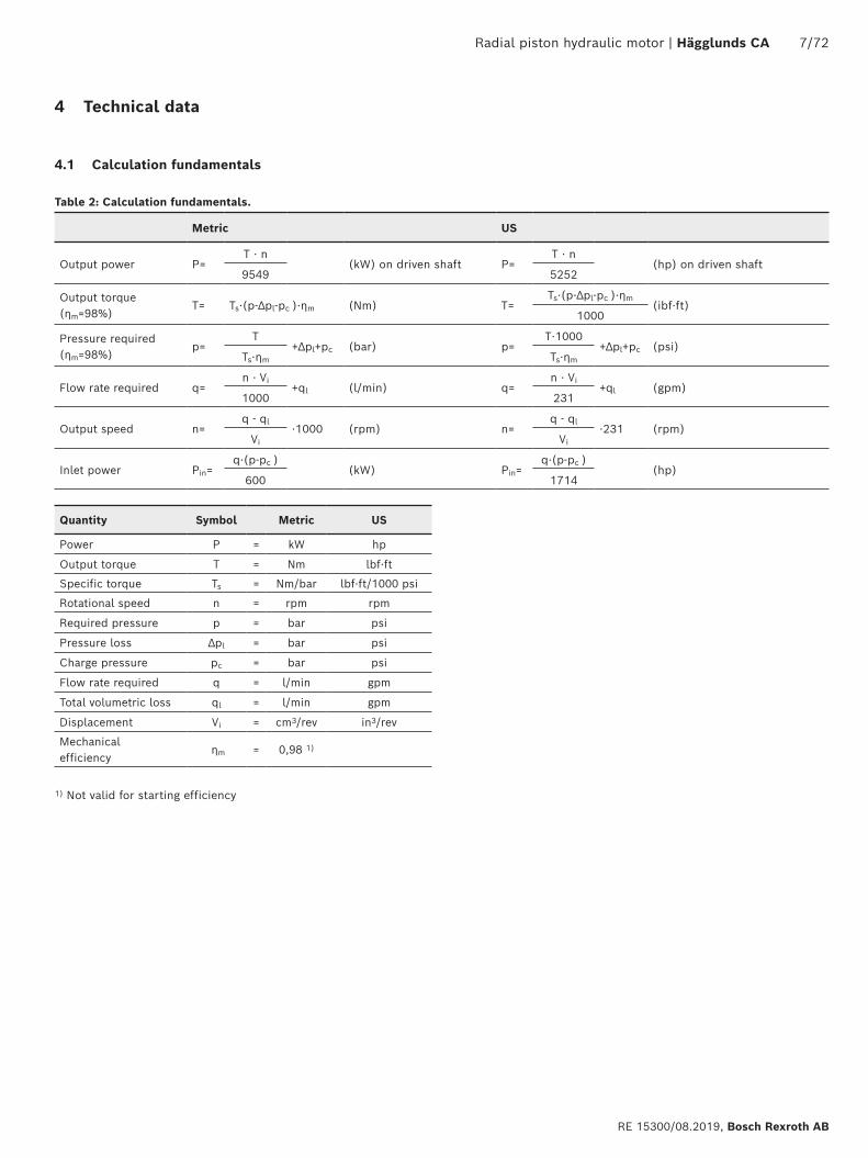
4 Technical data
4.1 Calculation fundamentals
Table 2: Calculation fundamentals.
Quantity Symbol Metric US
Power P = kW hp
Output torque T = Nm lbf·ft
Specific torque Ts = Nm/bar lbf·ft/1000 psi
Rotational speed n = rpm rpm
Required pressure p = bar psi
Pressure loss ∆pl = bar psi
Charge pressure pc = bar psi
Flow rate required q = l/min gpm
Total volumetric loss ql = l/min gpm
Displacement Vi = cm3/rev in3/rev
Mechanical efficiency
ηm = 0,98 1)
1) Not valid for starting efficiency
Metric US
Output power P=T ⋅ n
(kW) on driven shaft P=T ⋅ n
(hp) on driven shaft9549 5252
Output torque (ηm=98%)
T= Ts⋅(p-∆pl-pc )⋅ηm (Nm) T=Ts⋅(p-∆pl-pc )⋅ηm
(ibf⋅ft)1000
Pressure required (ηm=98%)
p=T
+∆pl+pc (bar) p=T⋅1000
+∆pl+pc (psi)Ts⋅ηm Ts⋅ηm
Flow rate required q=n ⋅ Vi
+ql (l/min) q=n ⋅ Vi
+ql (gpm)1000 231
Output speed n=q - ql
⋅1000 (rpm) n=q - ql
⋅231 (rpm)Vi Vi
Inlet power Pin=q⋅(p-pc )
(kW) Pin=q⋅(p-pc )
(hp)600 1714
8/72 Hägglunds CA | Radial piston hydraulic motor
Bosch Rexroth AB, RE 15300/08.2019
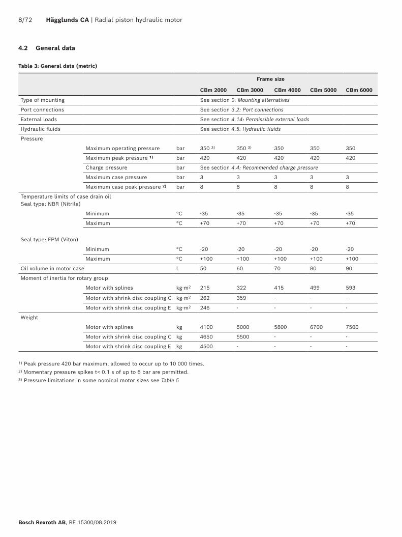
Table 3: General data (metric)
Frame size
CBm 2000 CBm 3000 CBm 4000 CBm 5000 CBm 6000
Type of mounting See section 9: Mounting alternatives
Port connections See section 3.2: Port connections
External loads See section 4.14: Permissible external loads
Hydraulic fluids See section 4.5: Hydraulic fluids
Pressure
Maximum operating pressure bar 350 3) 350 3) 350 350 350
Maximum peak pressure 1) bar 420 420 420 420 420
Charge pressure bar See section 4.4: Recommended charge pressure
Maximum case pressure bar 3 3 3 3 3
Maximum case peak pressure 2) bar 8 8 8 8 8
Temperature limits of case drain oilSeal type: NBR (Nitrile)
Minimum °C -35 -35 -35 -35 -35
Maximum °C +70 +70 +70 +70 +70
Seal type: FPM (Viton)
Minimum °C -20 -20 -20 -20 -20
Maximum °C +100 +100 +100 +100 +100
Oil volume in motor case l 50 60 70 80 90
Moment of inertia for rotary group
Motor with splines kg·m2 215 322 415 499 593
Motor with shrink disc coupling C kg·m2 262 359 - - -
Motor with shrink disc coupling E kg·m2 246 - - - -
Weight
Motor with splines kg 4100 5000 5800 6700 7500
Motor with shrink disc coupling C kg 4650 5500 - - -
Motor with shrink disc coupling E kg 4500 - - - -
1) Peak pressure 420 bar maximum, allowed to occur up to 10 000 times.2) Momentary pressure spikes t< 0.1 s of up to 8 bar are permitted.3) Pressure limitations in some nominal motor sizes see Table 5
4.2 General data

Radial piston hydraulic motor | Hägglunds CA 9/72
RE 15300/08.2019, Bosch Rexroth AB
Table 4: General data (US)
Frame size
CBm 2000 CBm 3000 CBm 4000 CBm 5000 CBm 6000
Type of mounting See section 9: Mounting alternatives
Port connections See section 3.2: Port connections
External loads See section 4.14: Permissible external loads
Hydraulic fluids See section 4.5: Hydraulic fluids
Pressure
Maximum operating pressure psi 5076 3) 5076 3) 5076 5076 5076
Maximum peak pressure 1) psi 6091 6091 6091 6091 6091
Charge pressure psi See section 4.4: Recommended charge pressure
Maximum case pressure psi 44 44 44 44 44
Maximum case peak pressure 2) psi 116 116 116 116 116
Temperature limits of case drain oilSeal type: NBR (Nitrile)
Minimum °F -31 -31 -31 -31 -31
Maximum °F +158 +158 +158 +158 +158
Seal type: FPM (Viton)
Minimum °F -4 -4 -4 -4 -4
Maximum °F +212 +212 +212 +212 +212
Oil volume in motor case US gal 13,2 15,8 18,5 21,1 23,8
Moment of inertia for rotary group
Motor with splines lb·ft2 5102 7642 9848 11841 14072
Motor with shrink disc coupling C lb·ft2 6217 8519 - - -
Motor with shrink disc coupling E lb·ft2 5838 - - - -
Weight
Motor with splines lb 9050 11000 12800 14750 16550
Motor with shrink disc coupling C lb 10250 12100 - - -
Motor with shrink disc coupling E lb 9900 - - - -
1) Peak pressure 6091 psi maximum, allowed to occur up to 10 000 times.2) Momentary pressure spikes t< 0.1 s of up to 116 psi are permitted3) Pressure limitations in some nominal motor sizes see Table 5
10/72 Hägglunds CA | Radial piston hydraulic motor
Bosch Rexroth AB, RE 15300/08.2019
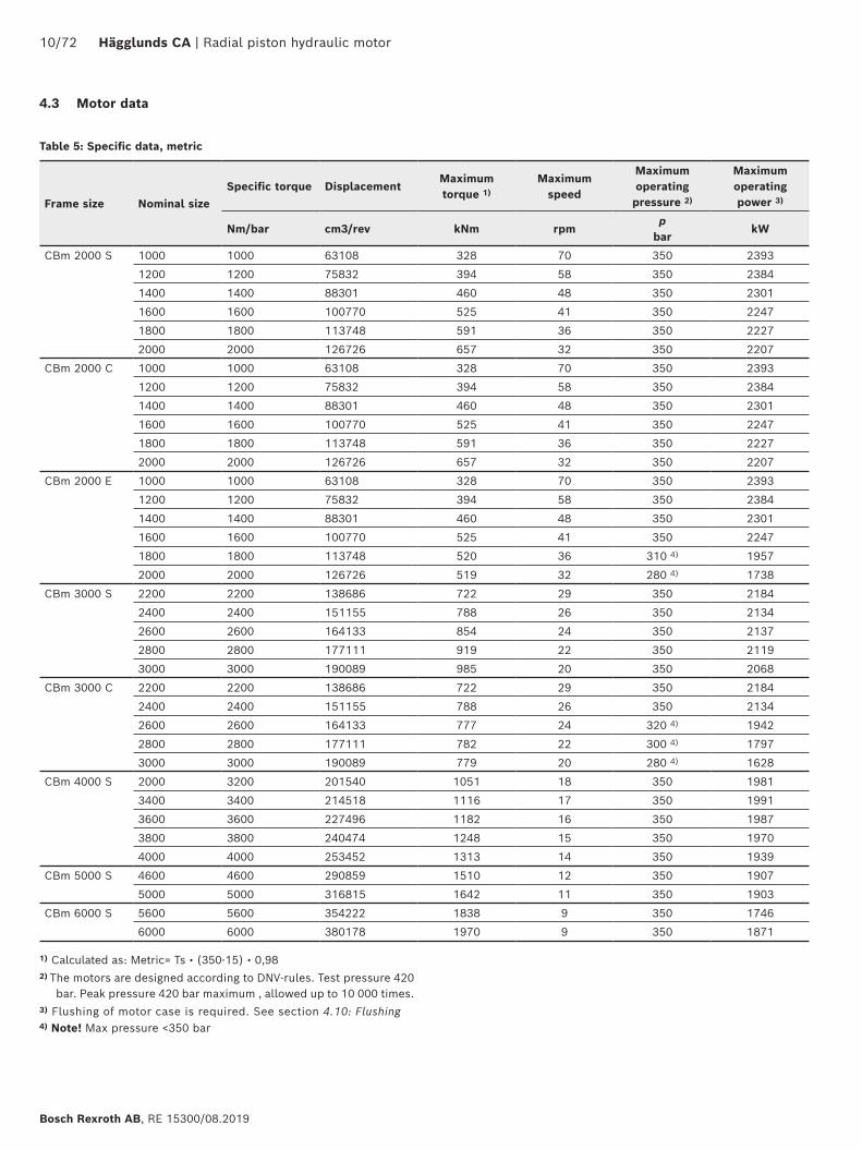
4.3 Motor data
Frame size Nominal sizeSpecific torque Displacement
Maximum torque 1)
Maximum speed
Maximum operating pressure 2)
Maximum operating power 3)
Nm/bar cm3/rev kNm rpmp
barkW
CBm 2000 S 1000 1000 63108 328 70 350 2393
1200 1200 75832 394 58 350 2384
1400 1400 88301 460 48 350 2301
1600 1600 100770 525 41 350 2247
1800 1800 113748 591 36 350 2227
2000 2000 126726 657 32 350 2207
CBm 2000 C 1000 1000 63108 328 70 350 2393
1200 1200 75832 394 58 350 2384
1400 1400 88301 460 48 350 2301
1600 1600 100770 525 41 350 2247
1800 1800 113748 591 36 350 2227
2000 2000 126726 657 32 350 2207
CBm 2000 E 1000 1000 63108 328 70 350 2393
1200 1200 75832 394 58 350 2384
1400 1400 88301 460 48 350 2301
1600 1600 100770 525 41 350 2247
1800 1800 113748 520 36 310 4) 1957
2000 2000 126726 519 32 280 4) 1738
CBm 3000 S 2200 2200 138686 722 29 350 2184
2400 2400 151155 788 26 350 2134
2600 2600 164133 854 24 350 2137
2800 2800 177111 919 22 350 2119
3000 3000 190089 985 20 350 2068
CBm 3000 C 2200 2200 138686 722 29 350 2184
2400 2400 151155 788 26 350 2134
2600 2600 164133 777 24 320 4) 1942
2800 2800 177111 782 22 300 4) 1797
3000 3000 190089 779 20 280 4) 1628
CBm 4000 S 2000 3200 201540 1051 18 350 1981
3400 3400 214518 1116 17 350 1991
3600 3600 227496 1182 16 350 1987
3800 3800 240474 1248 15 350 1970
4000 4000 253452 1313 14 350 1939
CBm 5000 S 4600 4600 290859 1510 12 350 1907
5000 5000 316815 1642 11 350 1903
CBm 6000 S 5600 5600 354222 1838 9 350 1746
6000 6000 380178 1970 9 350 1871
1) Calculated as: Metric= Ts • (350-15) • 0,982) The motors are designed according to DNV-rules. Test pressure 420
bar. Peak pressure 420 bar maximum , allowed up to 10 000 times.3) Flushing of motor case is required. See section 4.10: Flushing4) Note! Max pressure <350 bar
Table 5: Specific data, metric
Radial piston hydraulic motor | Hägglunds CA 11/72
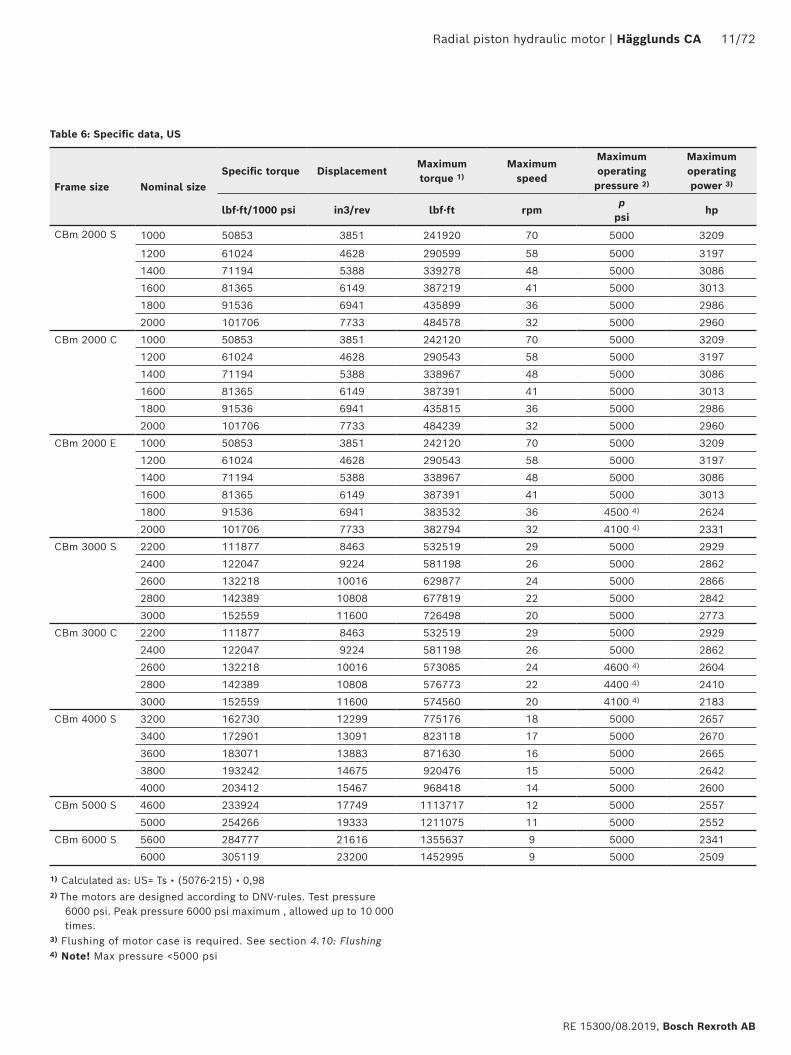
RE 15300/08.2019, Bosch Rexroth AB
Frame size Nominal sizeSpecific torque Displacement
Maximum torque 1)
Maximum speed
Maximum operating pressure 2)
Maximum operating power 3)
lbf·ft/1000 psi in3/rev lbf·ft rpmp
psihp
CBm 2000 S 1000 50853 3851 241920 70 5000 3209
1200 61024 4628 290599 58 5000 3197
1400 71194 5388 339278 48 5000 3086
1600 81365 6149 387219 41 5000 3013
1800 91536 6941 435899 36 5000 2986
2000 101706 7733 484578 32 5000 2960
CBm 2000 C 1000 50853 3851 242120 70 5000 3209
1200 61024 4628 290543 58 5000 3197
1400 71194 5388 338967 48 5000 3086
1600 81365 6149 387391 41 5000 3013
1800 91536 6941 435815 36 5000 2986
2000 101706 7733 484239 32 5000 2960
CBm 2000 E 1000 50853 3851 242120 70 5000 3209
1200 61024 4628 290543 58 5000 3197
1400 71194 5388 338967 48 5000 3086
1600 81365 6149 387391 41 5000 3013
1800 91536 6941 383532 36 4500 4) 2624
2000 101706 7733 382794 32 4100 4) 2331
CBm 3000 S 2200 111877 8463 532519 29 5000 2929
2400 122047 9224 581198 26 5000 2862
2600 132218 10016 629877 24 5000 2866
2800 142389 10808 677819 22 5000 2842
3000 152559 11600 726498 20 5000 2773
CBm 3000 C 2200 111877 8463 532519 29 5000 2929
2400 122047 9224 581198 26 5000 2862
2600 132218 10016 573085 24 4600 4) 2604
2800 142389 10808 576773 22 4400 4) 2410
3000 152559 11600 574560 20 4100 4) 2183
CBm 4000 S 3200 162730 12299 775176 18 5000 2657
3400 172901 13091 823118 17 5000 2670
3600 183071 13883 871630 16 5000 2665
3800 193242 14675 920476 15 5000 2642
4000 203412 15467 968418 14 5000 2600
CBm 5000 S 4600 233924 17749 1113717 12 5000 2557
5000 254266 19333 1211075 11 5000 2552
CBm 6000 S 5600 284777 21616 1355637 9 5000 2341
6000 305119 23200 1452995 9 5000 2509
Table 6: Specific data, US
1) Calculated as: US= Ts • (5076-215) • 0,982) The motors are designed according to DNV-rules. Test pressure
6000 psi. Peak pressure 6000 psi maximum , allowed up to 10 000 times.
3) Flushing of motor case is required. See section 4.10: Flushing4) Note! Max pressure <5000 psi
12/72 Hägglunds CA | Radial piston hydraulic motor
Bosch Rexroth AB, RE 15300/08.2019
Notice!The diagrams is valid for 1 bar (14,5 psi) case pressure. With increasing case pressure the charge pressure must be increased accordingly.
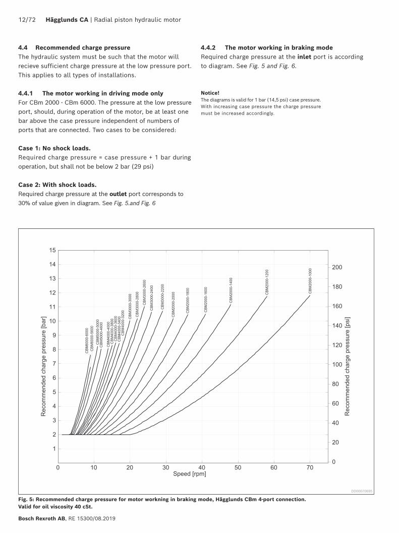
4.4 Recommended charge pressureThe hydraulic system must be such that the motor will recieve sufficient charge pressure at the low pressure port. This applies to all types of installations.
4.4.1 The motor working in driving mode onlyFor CBm 2000 - CBm 6000. The pressure at the low pressure port, should, during operation of the motor, be at least one bar above the case pressure independent of numbers of ports that are connected. Two cases to be considered:
Case 1: No shock loads.Required charge pressure = case pressure + 1 bar during operation, but shall not be below 2 bar (29 psi)
Case 2: With shock loads.Required charge pressure at the outlet port corresponds to 30% of value given in diagram. See Fig. 5.and Fig. 6
Fig. 5: Recommended charge pressure for motor workning in braking mode, Hägglunds CBm 4-port connection. Valid for oil viscosity 40 cSt.
DD00070695
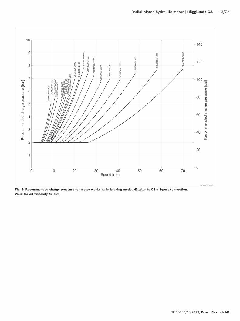
4.4.2 The motor working in braking modeRequired charge pressure at the inlet port is accordingto diagram. See Fig. 5 and Fig. 6.
Radial piston hydraulic motor | Hägglunds CA 13/72
RE 15300/08.2019, Bosch Rexroth AB
Fig. 6: Recommended charge pressure for motor workning in braking mode, Hägglunds CBm 8-port connection. Valid for oil viscosity 40 cSt.
DD00070696
14/72 Hägglunds CA | Radial piston hydraulic motor
Bosch Rexroth AB, RE 15300/08.2019
Details regarding the selection of hydraulic fluid
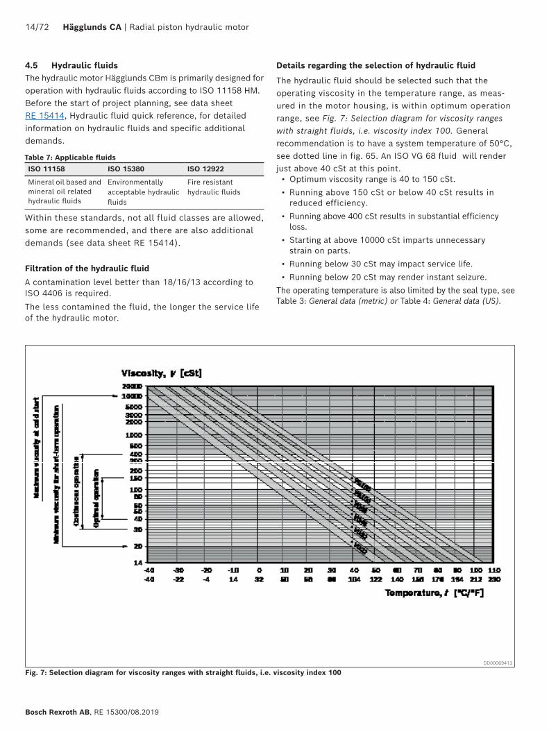
The hydraulic fluid should be selected such that the operating viscosity in the temperature range, as meas-ured in the motor housing, is within optimum operation range, see Fig. 7: Selection diagram for viscosity ranges with straight fluids, i.e. viscosity index 100. General recommendation is to have a system temperature of 50°C, see dotted line in fig. 65. An ISO VG 68 fluid will render just above 40 cSt at this point.• Optimum viscosity range is 40 to 150 cSt.• Running above 150 cSt or below 40 cSt results in
reduced efficiency.• Running above 400 cSt results in substantial efficiency
loss.• Starting at above 10000 cSt imparts unnecessary
strain on parts.• Running below 30 cSt may impact service life. • Running below 20 cSt may render instant seizure.
The operating temperature is also limited by the seal type, see Table 3: General data (metric) or Table 4: General data (US).
4.5 Hydraulic fluidsThe hydraulic motor Hägglunds CBm is primarily designed for operation with hydraulic fluids according to ISO 11158 HM. Before the start of project planning, see data sheet RE 15414, Hydraulic fluid quick reference, for detailed information on hydraulic fluids and specific additional demands.
ISO 11158 ISO 15380 ISO 12922
Mineral oil based and mineral oil related hydraulic fluids
Environmentally acceptable hydraulic fluids
Fire resistant hydraulic fluids
Within these standards, not all fluid classes are allowed, some are recommended, and there are also additional demands (see data sheet RE 15414).
Filtration of the hydraulic fluid
A contamination level better than 18/16/13 according to ISO 4406 is required.
The less contamined the fluid, the longer the service life of the hydraulic motor.
Table 7: Applicable fluids
Fig. 7: Selection diagram for viscosity ranges with straight fluids, i.e. viscosity index 100DD00069413
Radial piston hydraulic motor | Hägglunds CA 15/72
RE 15300/08.2019, Bosch Rexroth AB
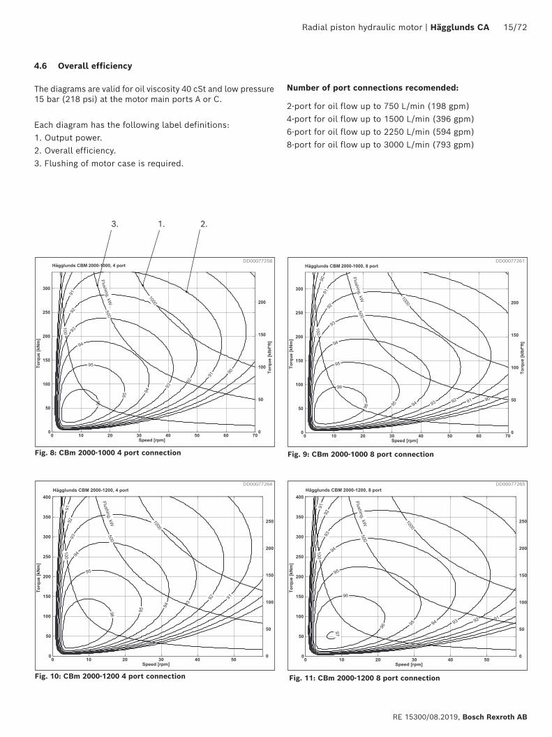
Fig. 8: CBm 2000-1000 4 port connection
Fig. 10: CBm 2000-1200 4 port connection
Fig. 9: CBm 2000-1000 8 port connection
Fig. 11: CBm 2000-1200 8 port connection
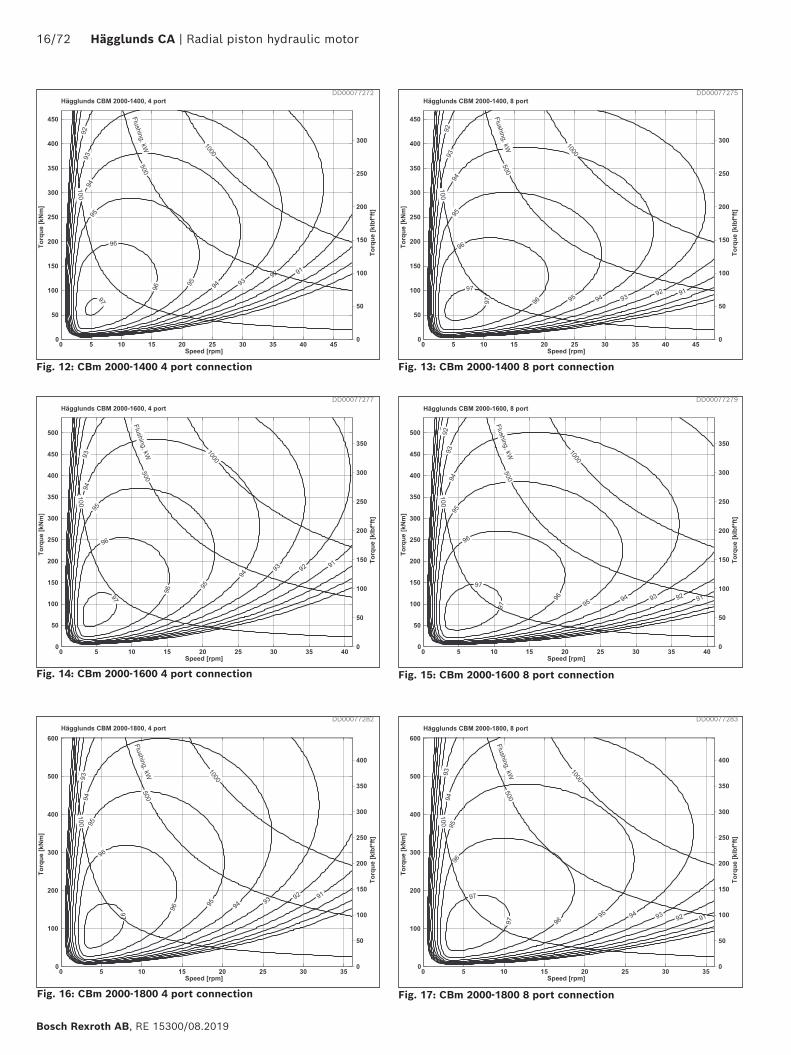
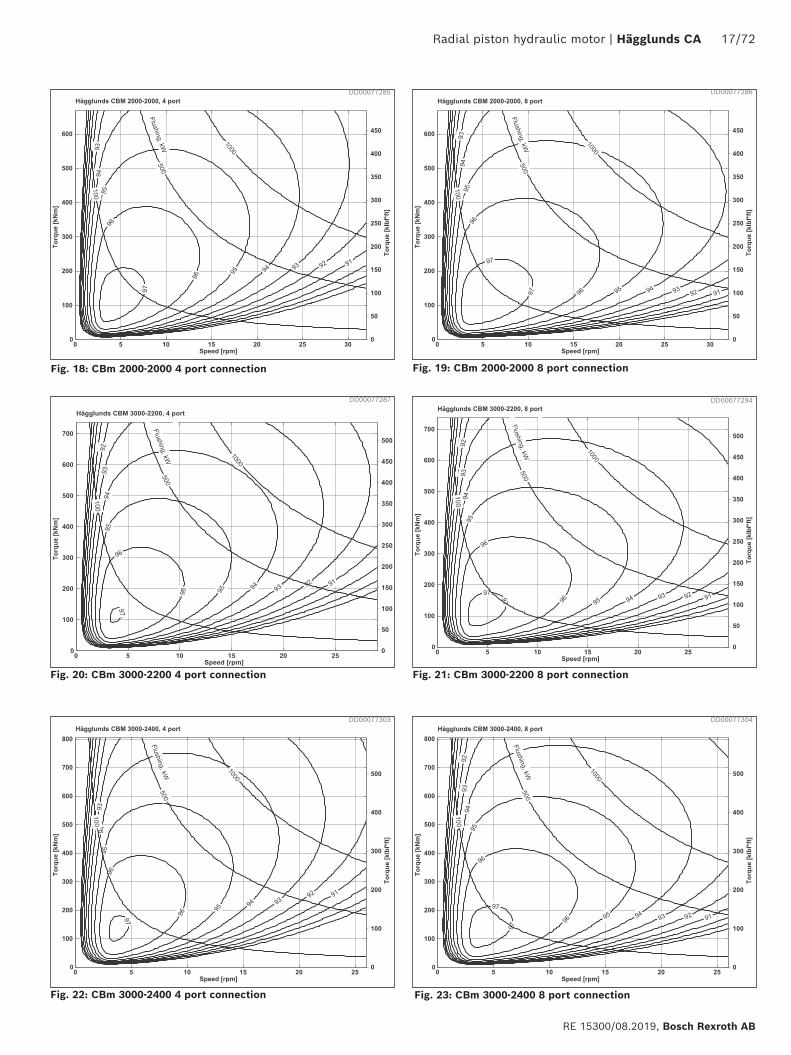
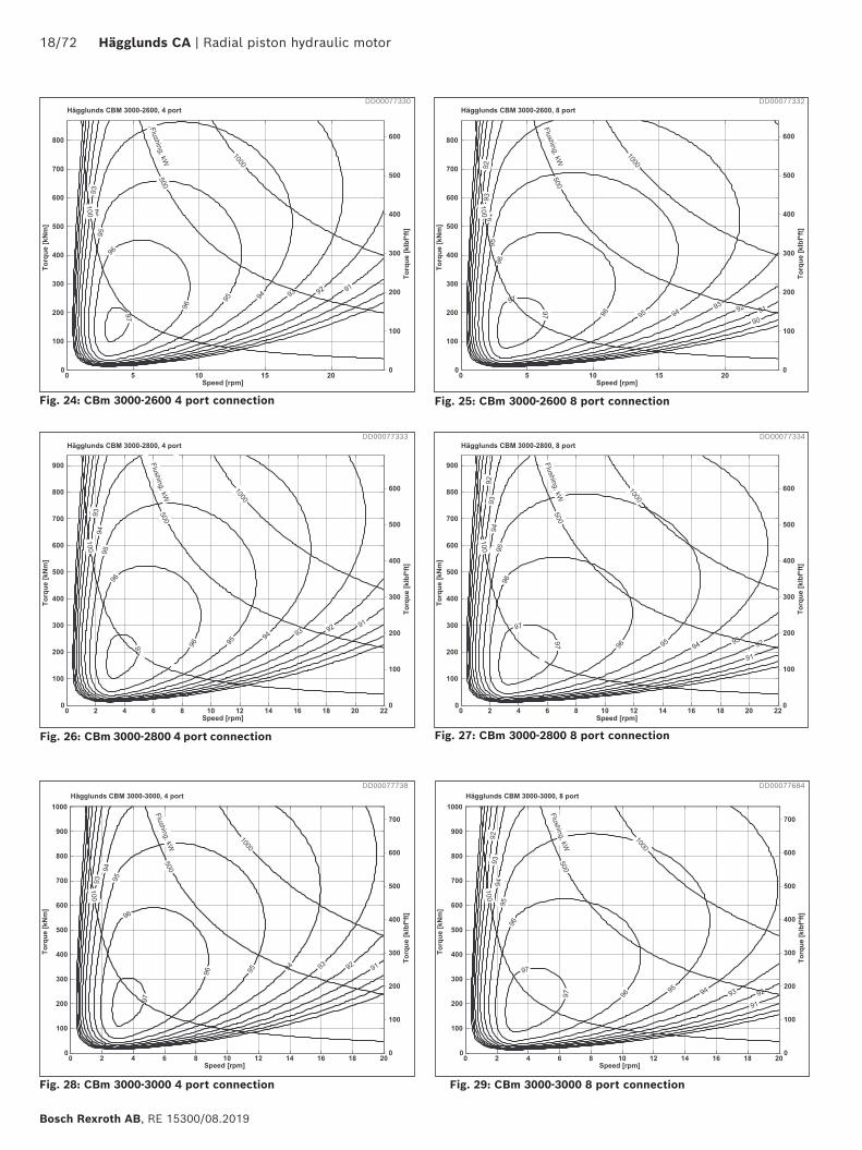
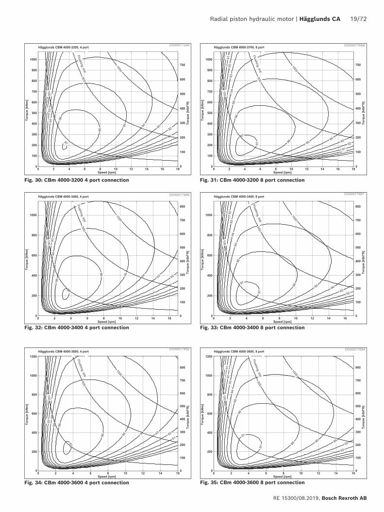
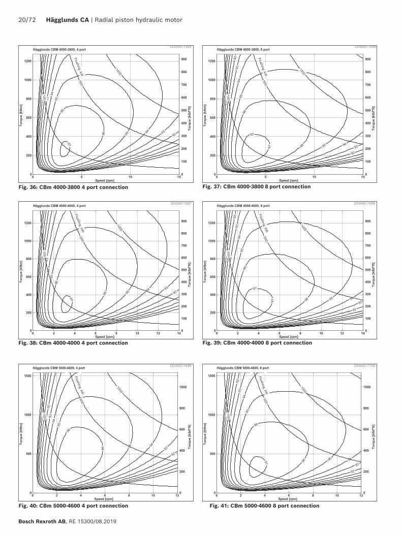
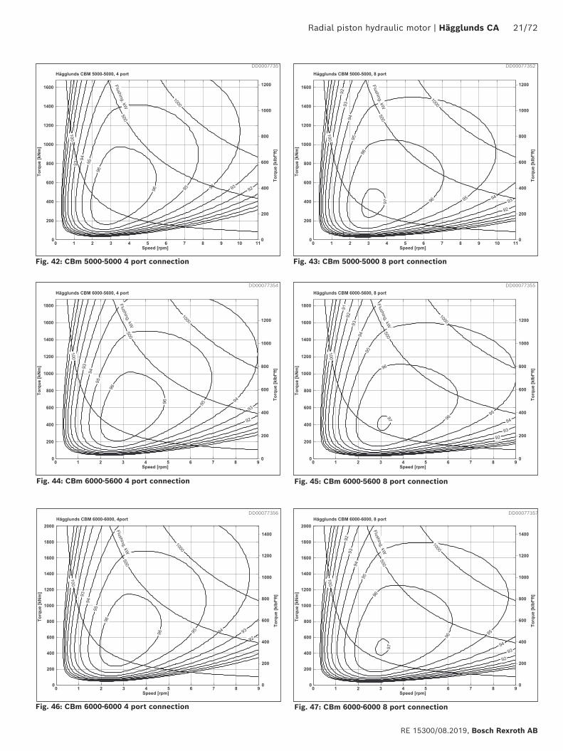
4.6 Overall efficiency
The diagrams are valid for oil viscosity 40 cSt and low pressure 15 bar (218 psi) at the motor main ports A or C.
Each diagram has the following label definitions:1. Output power.2. Overall efficiency.3. Flushing of motor case is required.
DD00077258 DD00077261
DD00077264 DD00077265
Number of port connections recomended: 2-port for oil flow up to 750 L/min (198 gpm)4-port for oil flow up to 1500 L/min (396 gpm)6-port for oil flow up to 2250 L/min (594 gpm)8-port for oil flow up to 3000 L/min (793 gpm)
1. 2.3.
16/72 Hägglunds CA | Radial piston hydraulic motor
Bosch Rexroth AB, RE 15300/08.2019
Fig. 12: CBm 2000-1400 4 port connection Fig. 13: CBm 2000-1400 8 port connection
Fig. 16: CBm 2000-1800 4 port connection
Fig. 14: CBm 2000-1600 4 port connection Fig. 15: CBm 2000-1600 8 port connection
Fig. 17: CBm 2000-1800 8 port connection
DD00077272
DD00077277
DD00077282
DD00077279
DD00077283
DD00077275
Radial piston hydraulic motor | Hägglunds CA 17/72
RE 15300/08.2019, Bosch Rexroth AB
Fig. 18: CBm 2000-2000 4 port connection
Fig. 21: CBm 3000-2200 8 port connection
Fig. 19: CBm 2000-2000 8 port connection
Fig. 20: CBm 3000-2200 4 port connection
Fig. 22: CBm 3000-2400 4 port connection Fig. 23: CBm 3000-2400 8 port connection
DD00077285
DD00077287
DD00077303
DD00077286
DD00077294
DD00077304
18/72 Hägglunds CA | Radial piston hydraulic motor
Bosch Rexroth AB, RE 15300/08.2019
Fig. 25: CBm 3000-2600 8 port connection
Fig. 26: CBm 3000-2800 4 port connection Fig. 27: CBm 3000-2800 8 port connection
Fig. 28: CBm 3000-3000 4 port connection Fig. 29: CBm 3000-3000 8 port connection
DD00077330 DD00077332
DD00077333 DD00077334
Fig. 24: CBm 3000-2600 4 port connection
DD00077738 DD00077684
Radial piston hydraulic motor | Hägglunds CA 19/72
RE 15300/08.2019, Bosch Rexroth AB
Fig. 29: CBm 3000-3000 8 port connection
Fig. 30: CBm 4000-3200 4 port connection Fig. 31: CBm 4000-3200 8 port connection
Fig. 32: CBm 4000-3400 4 port connection Fig. 33: CBm 4000-3400 8 port connection
Fig. 34: CBm 4000-3600 4 port connection Fig. 35: CBm 4000-3600 8 port connection
DD00077344
DD00077689
DD00077692
DD00077691
DD00077694
DD00077688
20/72 Hägglunds CA | Radial piston hydraulic motor
Bosch Rexroth AB, RE 15300/08.2019
Fig. 36: CBm 4000-3800 4 port connection Fig. 37: CBm 4000-3800 8 port connection
Fig. 38: CBm 4000-4000 4 port connection Fig. 39: CBm 4000-4000 8 port connection
Fig. 40: CBm 5000-4600 4 port connection Fig. 41: CBm 5000-4600 8 port connection
DD00077350
DD00077697
DD00077699
DD00077695
DD00077698
DD00077700
Radial piston hydraulic motor | Hägglunds CA 21/72
RE 15300/08.2019, Bosch Rexroth AB
Fig. 41: CBm 5000-4600 8 port connection
Fig. 42: CBm 5000-5000 4 port connection Fig. 43: CBm 5000-5000 8 port connection
Fig. 44: CBm 6000-5600 4 port connection Fig. 45: CBm 6000-5600 8 port connection
Fig. 46: CBm 6000-6000 4 port connection Fig. 47: CBm 6000-6000 8 port connection
DD00077351
DD00077354
DD00077356
DD00077352
DD00077355
DD00077357
22/72 Hägglunds CA | Radial piston hydraulic motor
Bosch Rexroth AB, RE 15300/08.2019
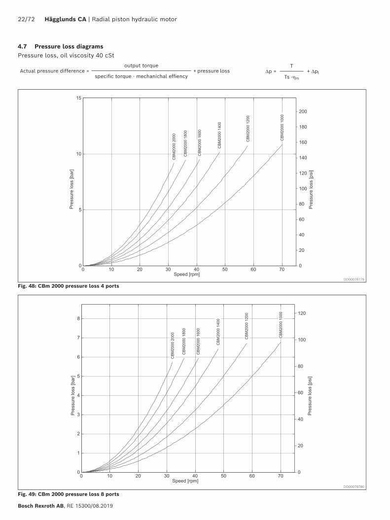
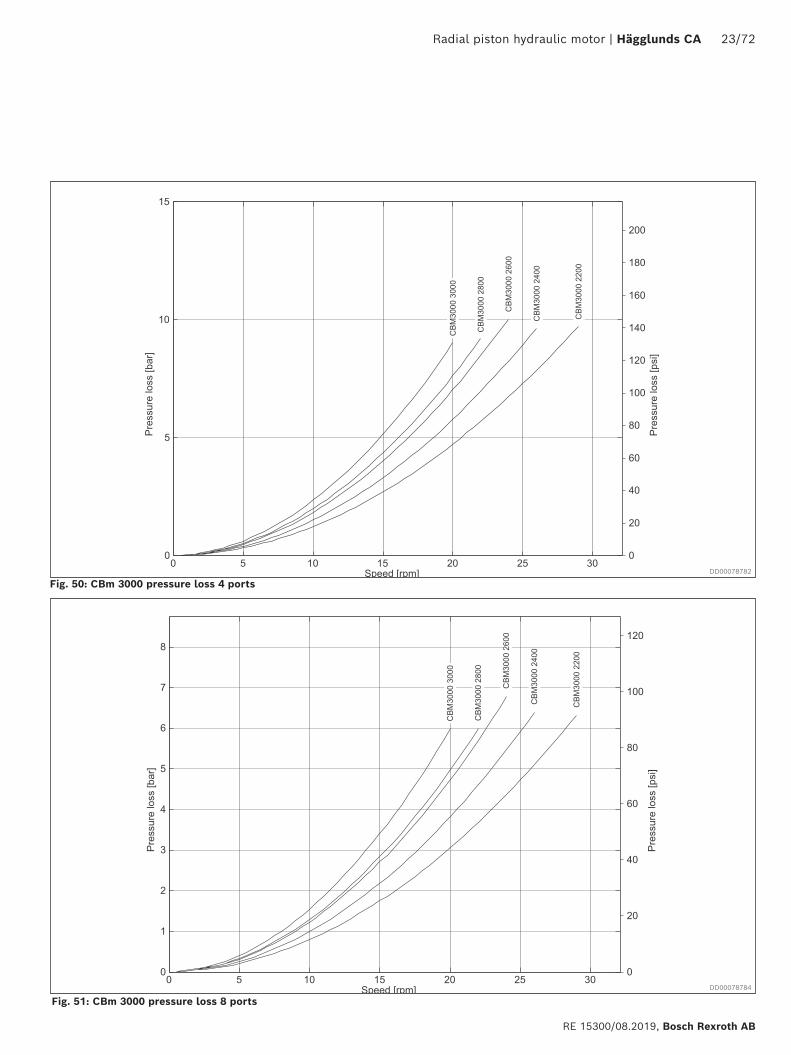
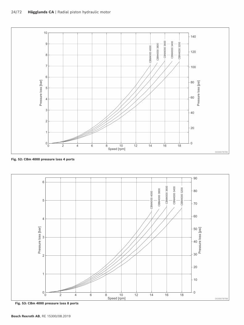
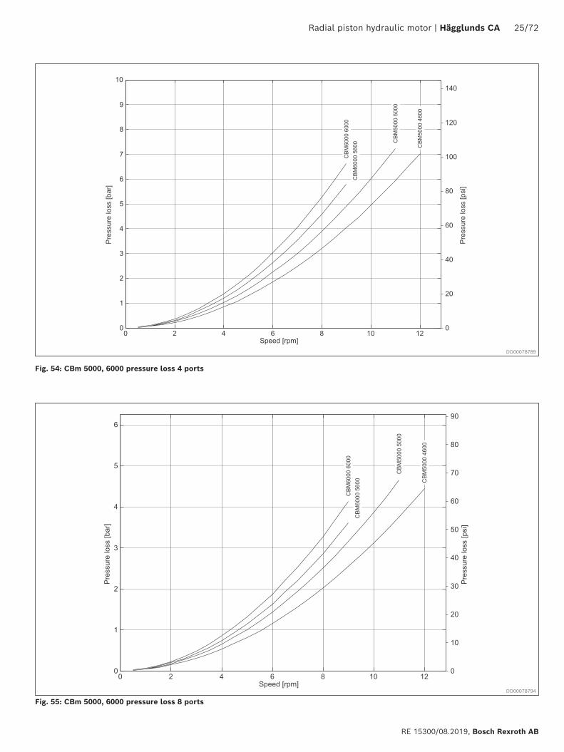
4.7 Pressure loss diagramsPressure loss, oil viscosity 40 cSt
Fig. 48: CBm 2000 pressure loss 4 ports
Fig. 49: CBm 2000 pressure loss 8 ports
∆p =T
+ ∆plTs ⋅ηm
Actual pressure difference = output torque
+ pressure lossspecific torque ⋅ mechanichal effiency
DD00078779
DD00078780
Radial piston hydraulic motor | Hägglunds CA 23/72
RE 15300/08.2019, Bosch Rexroth AB
Fig. 50: CBm 3000 pressure loss 4 ports
Fig. 51: CBm 3000 pressure loss 8 ports
DD00078782
DD00078784
24/72 Hägglunds CA | Radial piston hydraulic motor
Bosch Rexroth AB, RE 15300/08.2019
Fig. 52: CBm 4000 pressure loss 4 ports
Fig. 53: CBm 4000 pressure loss 8 ports
DD00078785
DD00078788
Radial piston hydraulic motor | Hägglunds CA 25/72
RE 15300/08.2019, Bosch Rexroth AB
Fig. 54: CBm 5000, 6000 pressure loss 4 ports
Fig. 55: CBm 5000, 6000 pressure loss 8 ports
DD00078789
DD00078794
26/72 Hägglunds CA | Radial piston hydraulic motor
Bosch Rexroth AB, RE 15300/08.2019
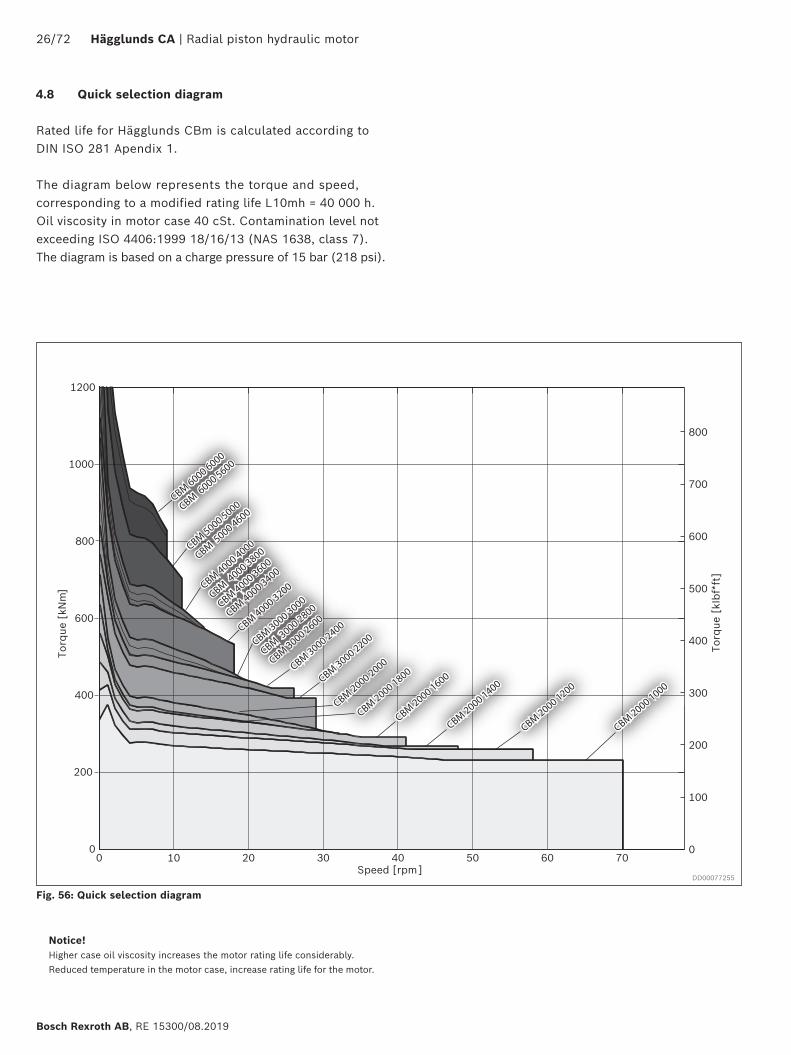
Fig. 56: Quick selection diagram
4.8 Quick selection diagram
Rated life for Hägglunds CBm is calculated according to DIN ISO 281 Apendix 1.
The diagram below represents the torque and speed, corresponding to a modified rating life L10mh = 40 000 h. Oil viscosity in motor case 40 cSt. Contamination level not exceeding ISO 4406:1999 18/16/13 (NAS 1638, class 7). The diagram is based on a charge pressure of 15 bar (218 psi).
Notice!Higher case oil viscosity increases the motor rating life considerably. Reduced temperature in the motor case, increase rating life for the motor.
0 10 20 30 40 50 60 700
200
400
600
800
1000
1200
Speed [rpm]
Torq
ue [
kNm
]
CBM 4000
−320
0
0
100
200
300
400
500
600
700
800
Torq
ue [
kIbf
*ft]
CBM 6000 6000
CBM 6000 5600
CBM 6000 6000
CBM 6000 5600
CBM 6000 6000
CBM 6000 5600
CBM 5000 5000
CBM 5000 4600
CBM 5000 5000
CBM 5000 4600
CBM 5000 5000
CBM 5000 4600
CBM 4000 4000
CBM 4000 3800
CBM 4000 3600
CBM 4000 3400CBM 4000 4000
CBM 4000 3800
CBM 4000 3600
CBM 4000 3400CBM 4000 4000
CBM 4000 3800
CBM 4000 3600
CBM 4000 3400
CBM 4000 3200
CBM 4000 3200
CBM 4000 3200
CBM 3000 3000
CBM 3000 2800
CBM 3000 2600
CBM 3000 3000
CBM 3000 2800
CBM 3000 2600
CBM 3000 3000
CBM 3000 2800
CBM 3000 2600
CBM 3000 2400
CBM 3000 2400
CBM 3000 2400
CBM 3000 2200
CBM 3000 2200
CBM 3000 2200
CBM 2000 2000
CBM 2000 2000
CBM 2000 2000
CBM 2000 1800
CBM 2000 1800
CBM 2000 1800
CBM 2000 1600
CBM 2000 1600
CBM 2000 1600
CBM 2000 1400
CBM 2000 1400
CBM 2000 1400
CBM 2000 1200
CBM 2000 1200
CBM 2000 1200
CBM 2000 1000
CBM 2000 1000
CBM 2000 1000
DD00077255
Radial piston hydraulic motor | Hägglunds CA 27/72
RE 15300/08.2019, Bosch Rexroth AB
4.9 Draining, venting and flushing of the motor
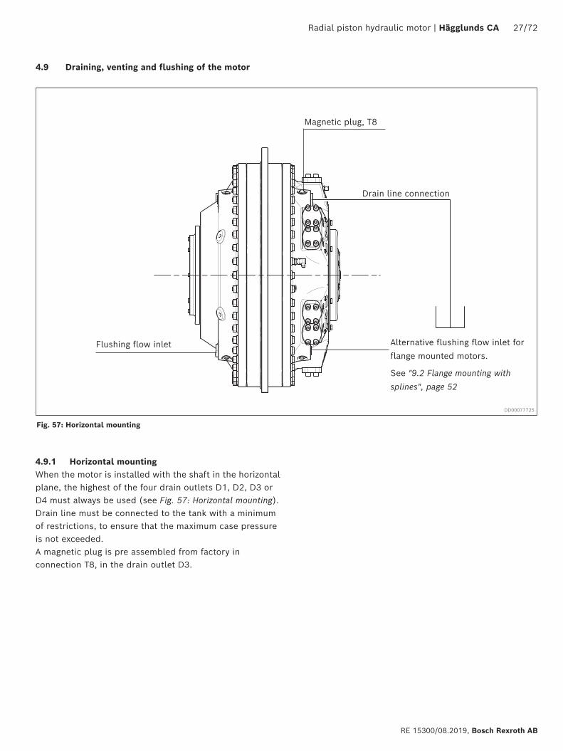
4.9.1 Horizontal mounting When the motor is installed with the shaft in the horizontal plane, the highest of the four drain outlets D1, D2, D3 or D4 must always be used (see Fig. 57: Horizontal mounting).Drain line must be connected to the tank with a minimum of restrictions, to ensure that the maximum case pressure is not exceeded.A magnetic plug is pre assembled from factory in connection T8, in the drain outlet D3.
Fig. 57: Horizontal mounting
Magnetic plug, T8
Flushing flow inlet Alternative flushing flow inlet for flange mounted motors.
See "9.2 Flange mounting with
splines", page 52
DD00077725
Drain line connection
28/72 Hägglunds CA | Radial piston hydraulic motor
Bosch Rexroth AB, RE 15300/08.2019
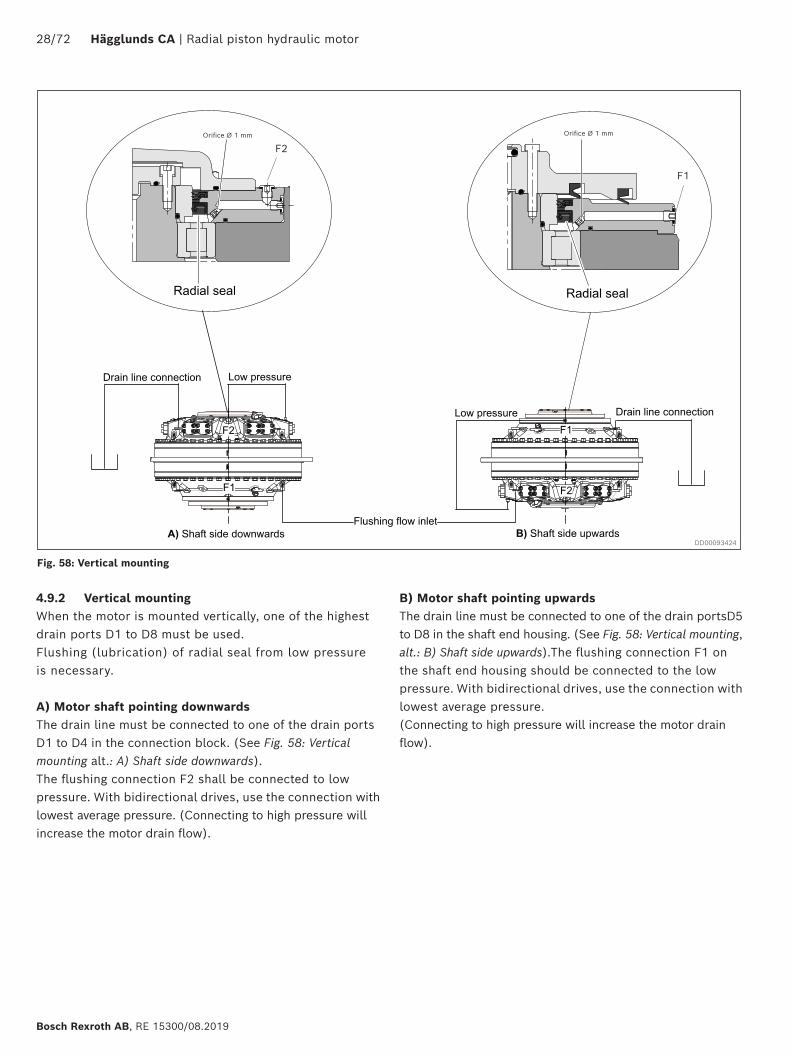
4.9.2 Vertical mountingWhen the motor is mounted vertically, one of the highest drain ports D1 to D8 must be used. Flushing (lubrication) of radial seal from low pressure is necessary.
A) Motor shaft pointing downwardsThe drain line must be connected to one of the drain ports D1 to D4 in the connection block. (See Fig. 58: Vertical mounting alt.: A) Shaft side downwards).The flushing connection F2 shall be connected to low pressure. With bidirectional drives, use the connection with lowest average pressure. (Connecting to high pressure will increase the motor drain flow).
DD00093424
Orifice Ø 1 mm Orifice Ø 1 mm
B) Motor shaft pointing upwards The drain line must be connected to one of the drain portsD5 to D8 in the shaft end housing. (See Fig. 58: Vertical mounting, alt.: B) Shaft side upwards).The flushing connection F1 on the shaft end housing should be connected to the low pressure. With bidirectional drives, use the connection with lowest average pressure. (Connecting to high pressure will increase the motor drain flow).
Fig. 58: Vertical mounting
F2
F1
Radial piston hydraulic motor | Hägglunds CA 29/72
RE 15300/08.2019, Bosch Rexroth AB
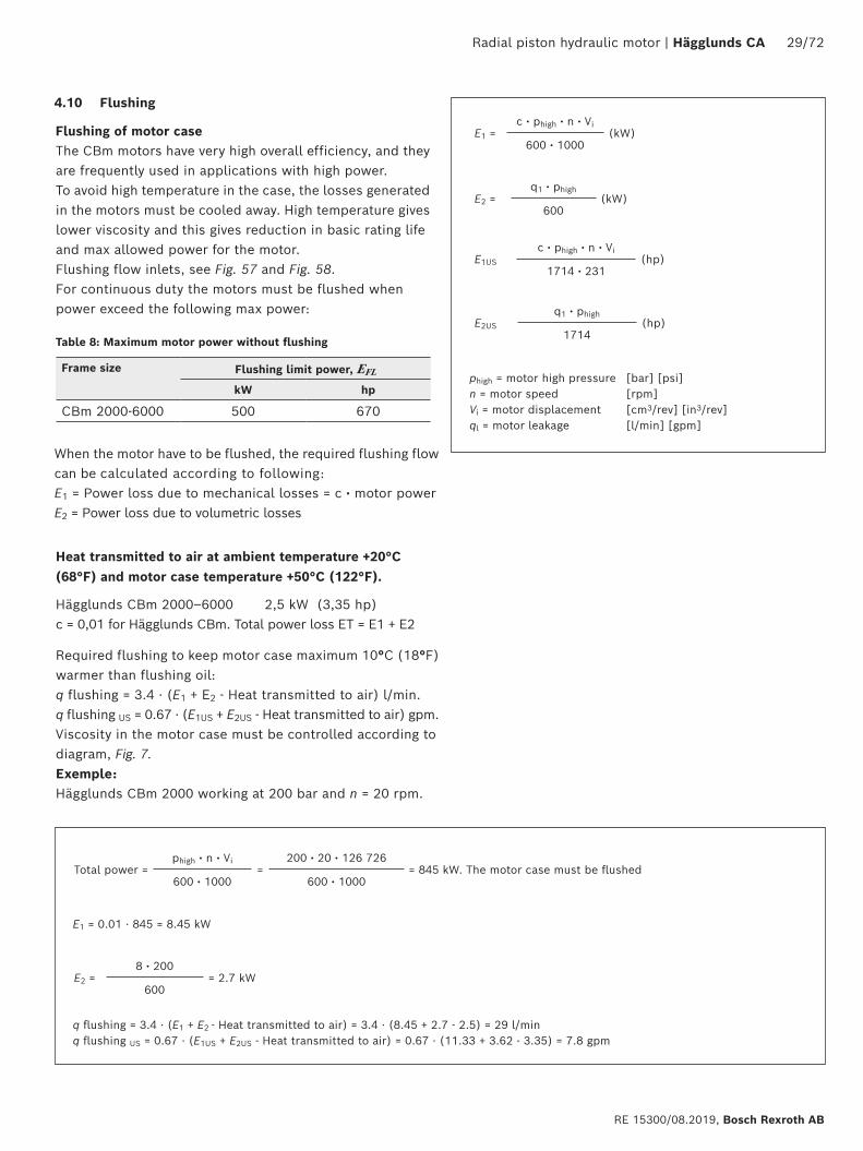
Required flushing to keep motor case maximum 10°C (18°F) warmer than flushing oil: q flushing = 3.4 · (E1 + E2 - Heat transmitted to air) l/min. q flushing US = 0.67 · (E1US + E2US - Heat transmitted to air) gpm.Viscosity in the motor case must be controlled according to diagram, Fig. 7. Exemple: Hägglunds CBm 2000 working at 200 bar and n = 20 rpm.
The CBm motors have very high overall efficiency, and they are frequently used in applications with high power.To avoid high temperature in the case, the losses generated in the motors must be cooled away. High temperature gives lower viscosity and this gives reduction in basic rating life and max allowed power for the motor. Flushing flow inlets, see Fig. 57 and Fig. 58.For continuous duty the motors must be flushed when power exceed the following max power:
Flushing of motor case
Heat transmitted to air at ambient temperature +20°C (68°F) and motor case temperature +50°C (122°F).
Hägglunds CBm 2000–6000 2,5 kW (3,35 hp)c = 0,01 for Hägglunds CBm. Total power loss ET = E1 + E2
E1 = 0.01 · 845 = 8.45 kW
When the motor have to be flushed, the required flushing flow can be calculated according to following:E1 = Power loss due to mechanical losses = c ⋅ motor powerE2 = Power loss due to volumetric losses
Total power =phigh ⋅ n ⋅ Vi
=200 ⋅ 20 ⋅ 126 726
= 845 kW. The motor case must be flushed600 ⋅ 1000 600 ⋅ 1000
E2 =8 ⋅ 200
= 2.7 kW600
q flushing = 3.4 · (E1 + E2 - Heat transmitted to air) = 3.4 · (8.45 + 2.7 - 2.5) = 29 l/minq flushing US = 0.67 · (E1US + E2US - Heat transmitted to air) = 0.67 · (11.33 + 3.62 - 3.35) = 7.8 gpm
E1 =c ⋅ phigh ⋅ n ⋅ Vi
(kW)600 ⋅ 1000
E1US
c ⋅ phigh ⋅ n ⋅ Vi(hp)
1714 ⋅ 231
E2 =q1 ⋅ phigh
(kW)600
E2US
q1 ⋅ phigh(hp)
1714
phigh = motor high pressure [bar] [psi] n = motor speed [rpm] Vi = motor displacement [cm3/rev] [in3/rev] ql = motor leakage [l/min] [gpm]
Table 8: Maximum motor power without flushing
Frame size Flushing limit power, EFL
kW hp
CBm 2000-6000 500 670
4.10 Flushing
30/72 Hägglunds CA | Radial piston hydraulic motor
Bosch Rexroth AB, RE 15300/08.2019
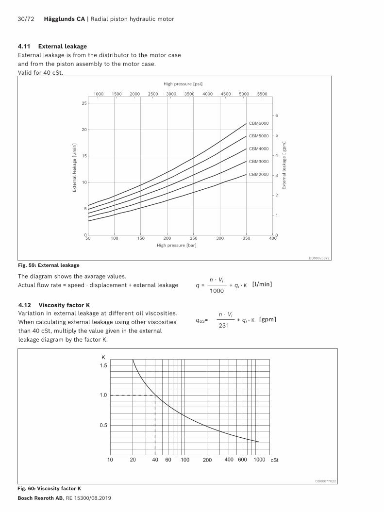
4.11 External leakageExternal leakage is from the distributor to the motor case and from the piston assembly to the motor case. Valid for 40 cSt.
1000 1500 2000 2500 3000 3500 4000 4500 5000 5500
High pressure [psi]
25
CBM6000
0
1
2
3
4
5
6
Exte
rnal
lea
kage
[ g
pm
]
CBM5000
CBM4000
CBM3000
CBM2000
50 100 150 200 250 300 350 4000
5
10
15
20
Exte
rnal
lea
kage
[l/
min
]
High pressure [bar]
The diagram shows the avarage values. Actual flow rate = speed ⋅ displacement + external leakage q =
n ⋅ Vi+ qi ⋅ K
1000
qUS=n ⋅ Vi
+ qi ⋅ K231
Fig. 59: External leakage
Fig. 60: Viscosity factor K
DD00075072
[l/min]
[gpm]Variation in external leakage at different oil viscosities. When calculating external leakage using other viscosities than 40 cSt, multiply the value given in the external leakage diagram by the factor K.
4.12 Viscosity factor K
DD00077022
Radial piston hydraulic motor | Hägglunds CA 31/72
RE 15300/08.2019, Bosch Rexroth AB
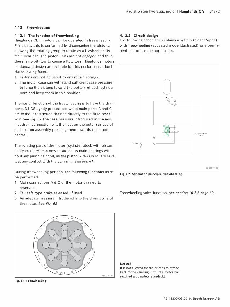
Hägglunds CBm motors can be operated in freewheeling.Principally this is performed by disengaging the pistons, allowing the rotating group to rotate as a flywheel on its main bearings. The piston units are not engaged and thus there is no oil flow to cause a flow loss, Hägglunds motors of standard design are suitable for this performance due to the following facts:1. Pistons are not actuated by any return springs.2. The motor case can withstand sufficient case pressure
to force the pistons toward the bottom of each cylinder bore and keep them in this position.
The basic function of the freewheeling is to have the drain ports D1-D8 lightly pressurized while main ports A and C are without restriction drained directly to the fluid reser-voir. See Fig. 62 The case pressure introduced in the nor-mal drain connection will then act on the outer surface of each piston assembly pressing them towards the motor centre.
The rotating part of the motor (cylinder block with piston and cam roller) can now rotate on its main bearings wit-hout any pumping of oil, as the piston with cam rollers have lost any contact with the cam ring. See Fig. 61.
During freewheeling periods, the following functions must be performed:1. Main connections A & C of the motor drained to
reservoir.2. Fail-safe type brake released, if used.3. An adeuate pressure introduced into the drain ports of
the motor. See Fig. 63
Notice!It is not allowed for the pistons to extend back to the camring, until the motor has reached a complete standstill.
4.13 Freewheeling
4.13.1 The function of freewheeling
Fig. 61: Freewheeling
Fig. 62: Schematic principle freewheeling.
DD00075541
DD00077405
4.13.2 Circuit designThe following schematic explains a system (closed/open) with freewheeling (activated mode illustrated) as a perma-nent feature for the application.
Freewheeling valve function, see section 10.6.6 page 69.
A C
P A
P C1-3 bar
D2
D1
Flushing flow inlet
32/72 Hägglunds CA | Radial piston hydraulic motor
Bosch Rexroth AB, RE 15300/08.2019
VF =Vi
2 NL
VF = Needed Freewheeling volume [cm3] or(in3)
Vi = Total displacement of the motor [cm3] or(in3)NL = 18 (No of lobes for one camring)
4.13.3 Oil volume for freewheelingFreewheeling conditions are obtained by pressurizing the case via the drain connections and drain the main ports to tank. To retract all pistons completely, a certain oil volume is required depending upon motor type. This oil volume can be calculated from the following:
To use Hägglunds CBm motor in freewheeling mode must following be maintained:• The motor must be pressurized all the time when the
motor is in freewheeling mode, see Fig. 63.• The motor must be flushed all the time when the
motor is in frewheeling mode, see Fig. 63.
An accumulator can be added into the circuit to shorten the time to retract all the pistons completely, see Fig. 63.
An accumulator can be added into the circuit to reduce the pressure spikes in the motor case when the pistons are extracted, see Fig. 62.
Radial piston hydraulic motor | Hägglunds CA 33/72
RE 15300/08.2019, Bosch Rexroth AB
0
20
40
60
80
100
120
0
10
20
30
40
50
60
70
80
90
100
0 50 100 150 200
Free wheeling speed [rpm]
Requ
ired
case
flus
hing
Continiousoperation
Intermittent *)operation
Emergencyoperation only
Pow
er los
s [h
p],
Cas
e fl
ushi
ng [
gpm
]
Pow
er los
s [k
W],
Cas
e fl
ushi
ng [
l/m
in]
Case pressure 1.5 bar Case pressure 2.0 bar Case pressure 3.0 bar
[l/min] [kW]
100
90
80
70
60
50
40
30
20
10
0
Power loss
0 50 100 150 200
120
100
80
100
90
80
70
60
50
40
30
20
10
0
60
40
20
0
26.4
21.1
15.9
10.6
5.3
0.0
[hp] [gpm]
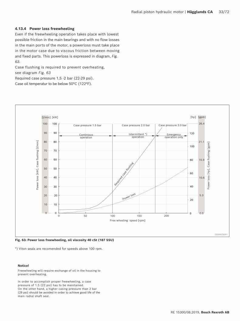
Notice! Freewheeling will require exchange of oil in the housing to prevent overheating.
In order to accomplish proper freewheeling, a case pressure of 1.5 (22 psi) has to be maintained. On the other hand, a higher casing pressure than 2 bar (29 psi) should be avoided in order to achieve good life of the main radial shaft seal.
4.13.4 Power loss freewheelingEven if the freewheeling operation takes place with lowest possible friction in the main bearings and with no flow losses in the main ports of the motor, a powerloss must take place in the motor case due to viscous friction between moving and fixed parts. This powerloss is expressed in diagram, Fig. 63.Case flushing is required to prevent overheating, see diagram Fig. 63Required case pressure 1,5 -2 bar (22-29 psi). Case oil temperatur to be below 50°C (122°F).
Fig. 63: Power loss freewheeling, oil viscosity 40 cSt (187 SSU)
DD00075091
*) Viton seals are recomended for speeds above 100 rpm.
34/72 Hägglunds CA | Radial piston hydraulic motor
Bosch Rexroth AB, RE 15300/08.2019
4.14 Permissible external loads
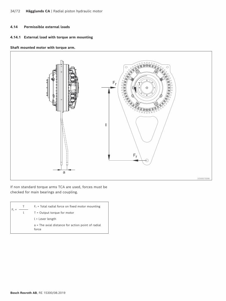
4.14.1 External load with torque arm mounting
If non standard torque arms TCA are used, forces must be checked for main bearings and coupling.
Shaft mounted motor with torque arm.
Fr =T Fr = Total radial force on fixed motor mounting
l T = Output torque for motor
l = Lever length
a = The axial distance for action point of radial force
DD00075098
Radial piston hydraulic motor | Hägglunds CA 35/72
RE 15300/08.2019, Bosch Rexroth AB
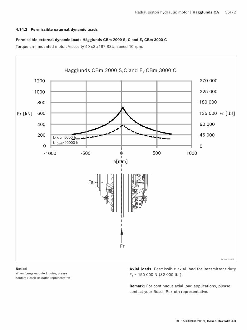
Axial loads: Permissible axial load for intermittent duty Fa = 150 000 N (32 000 lbf).
Remark: For continuous axial load applications, please contact your Bosch Rexroth representative.
4.14.2 Permissible external dynamic loads
Permissible external dynamic loads Hägglunds CBm 2000 S, C and E, CBm 3000 C
Torque arm mounted motor. Viscosity 40 cSt/187 SSU, speed 10 rpm.
a[mm]
0
200
400
600
800
1000
1200
-1000 -500 0 1000
Fr [kN]
Hägglunds CBM 2000
270 000
Fr [lbf]
0
45 000
90 000
135 000
180 000
225 000
500
Fr
Fa
L10aah=5000 hL10aah=40000 h
Notice! When flange mounted motor, please contact Bosch Rexroths representative.
DD00075548
Hägglunds CBm 2000 S,C and E, CBm 3000 C
36/72 Hägglunds CA | Radial piston hydraulic motor
Bosch Rexroth AB, RE 15300/08.2019
Hägglunds CBM 3000
0
200
400
600
800
1000
1200
Fr [kN]
270 000
Fr [lbf]
0
45 000
90 000
135 000
180 000
225 000
a[mm]
-800 -200 0 800600-600 -400 200 400
Fa
Fr
L10aah = 5000 h
L10aah = 40000 h
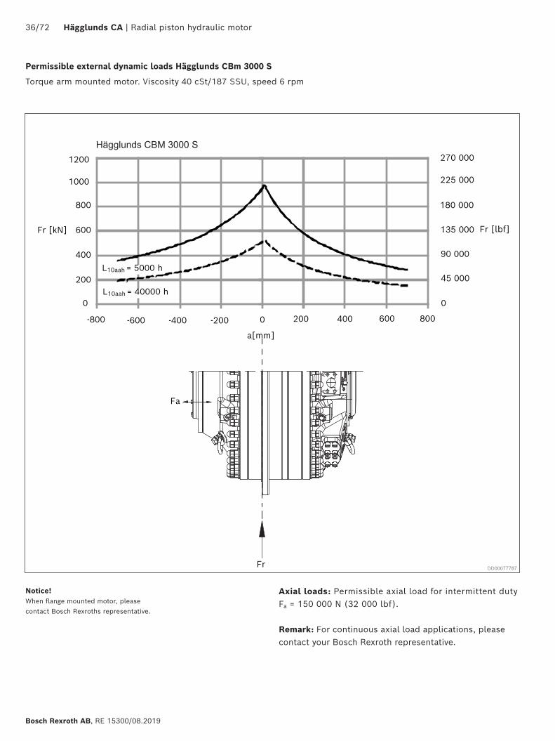
Permissible external dynamic loads Hägglunds CBm 3000 S
Torque arm mounted motor. Viscosity 40 cSt/187 SSU, speed 6 rpm
Axial loads: Permissible axial load for intermittent duty Fa = 150 000 N (32 000 lbf).
Remark: For continuous axial load applications, please contact your Bosch Rexroth representative.
Notice! When flange mounted motor, please contact Bosch Rexroths representative.
DD00077787
Hägglunds CBM 3000 S
Radial piston hydraulic motor | Hägglunds CA 37/72
RE 15300/08.2019, Bosch Rexroth AB
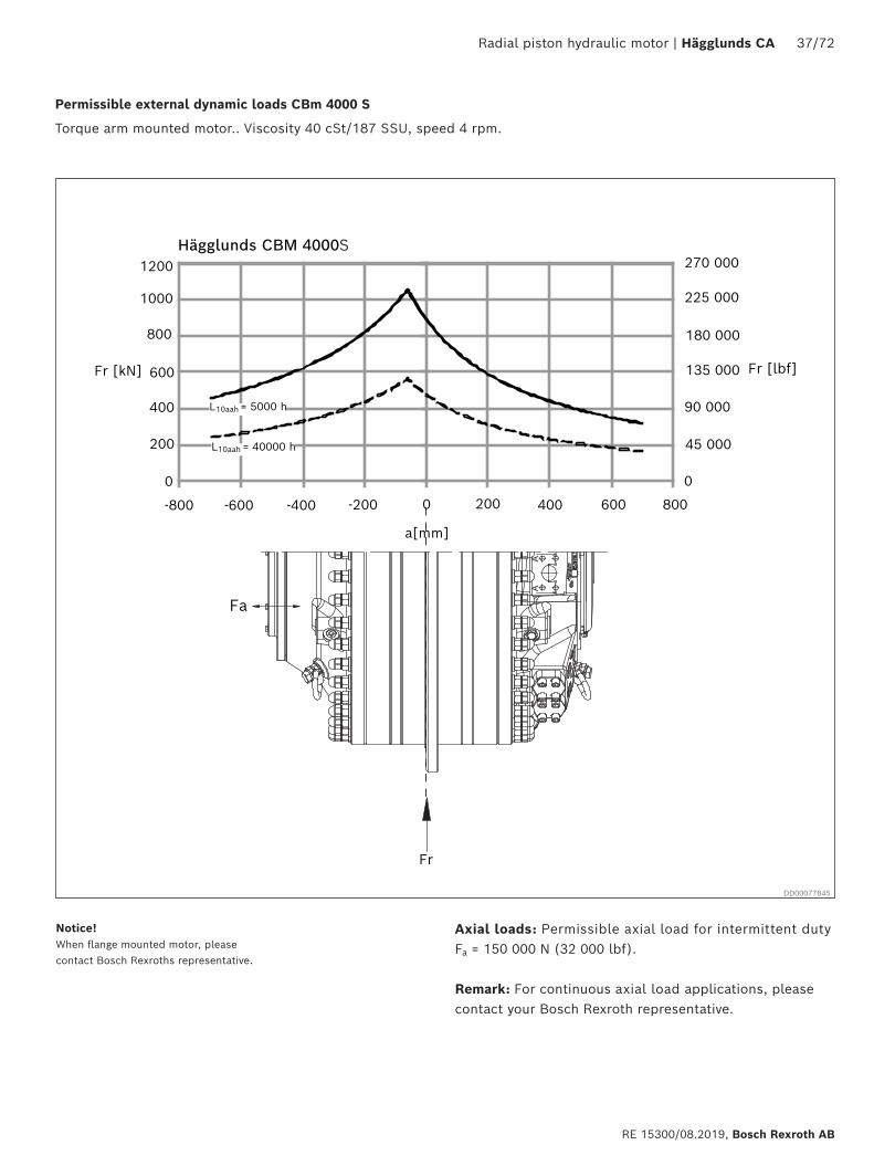
Permissible external dynamic loads CBm 4000 S
Torque arm mounted motor.. Viscosity 40 cSt/187 SSU, speed 4 rpm.
Axial loads: Permissible axial load for intermittent dutyFa = 150 000 N (32 000 lbf).
Remark: For continuous axial load applications, please contact your Bosch Rexroth representative.
Hägglunds CBM 4000
0
200
400
600
800
1000
1200
Fr [kN]
270 000
Fr [lbf]
0
45 000
90 000
135 000
180 000
225 000
a[mm]
-800 -200 0 800600-600 -400 200 400
L10aah = 5000 h
L10aah = 40000 h
Fr
Fa
Notice! When flange mounted motor, please contact Bosch Rexroths representative.
DD00077845
S
38/72 Hägglunds CA | Radial piston hydraulic motor
Bosch Rexroth AB, RE 15300/08.2019
Hägglunds CBM 5000
200
400
600
800
1000
1200
Fr [kN]
0
-800 -200 0 800600-600 -400 200 400
270 000
Fr [lbf]
0
45 000
90 000
135 000
180 000
225 000
L10aah = 5000 h
L10aah = 40000 h
Fr
Fa
a[mm]
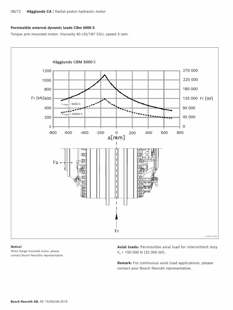
Permissible external dynamic loads CBm 5000 S
Torque arm mounted motor. Viscosity 40 cSt/187 SSU, speed 3 rpm.
Axial loads: Permissible axial load for intermittent dutyFa = 150 000 N (32 000 lbf).
Remark: For continuous axial load applications, please contact your Bosch Rexroth representative.
Notice! When flange mounted motor, please contact Bosch Rexroths representative.
DD00077846
S
Radial piston hydraulic motor | Hägglunds CA 39/72
RE 15300/08.2019, Bosch Rexroth AB
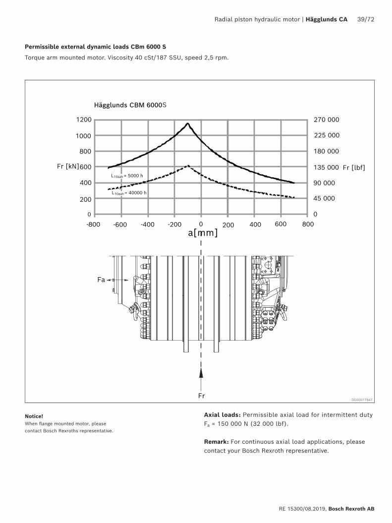
Permissible external dynamic loads CBm 6000 S
Torque arm mounted motor. Viscosity 40 cSt/187 SSU, speed 2,5 rpm.
Axial loads: Permissible axial load for intermittent dutyFa = 150 000 N (32 000 lbf).
Remark: For continuous axial load applications, please contact your Bosch Rexroth representative.
Hägglunds CBM 6000
200
400
600
800
1000
1200
Fr [kN]
0
270 000
Fr [lbf]
0
45 000
90 000
135 000
180 000
225 000
-800 -200 0 800600-600 -400 200 400
L10aah = 5000 h
L10aah = 40000 h
Fr
Fa
a[mm]
Notice! When flange mounted motor, please contact Bosch Rexroths representative.
DD00077847
S
40/72 Hägglunds CA | Radial piston hydraulic motor
Bosch Rexroth AB, RE 15300/08.2019
Fr [kN]
899 2404000
3500
2500
1500
3000
2000
1000
500
0
786 835
674 430
562 025
449 620
337 215
224 810
112 405
0
Fr [lbf]
-800 -600 -400 -200 200 400 600 8000
Hägglunds CBM 2000, permissible static load
a [mm]
Fr [kN]
4000
3500
2500
1500
3000
2000
1000
500
0-800 -600 -400 -200 200 400 600 8000
Hägglunds CBM 3000, permissible static load
a [mm]
899 240
786 835
674 430
562 025
449 620
337 215
224 810
112 405
0
Fr [lbf]
Fr [kN]
4000
3500
2500
1500
3000
2000
1000
500
0-800 -600 -400 -200 200 400 600 8000
Hägglunds CBM 4000, permissible static load
a [mm]
899 240
786 835
674 430
562 025
449 620
337 215
224 810
112 405
0
Fr [lbf]
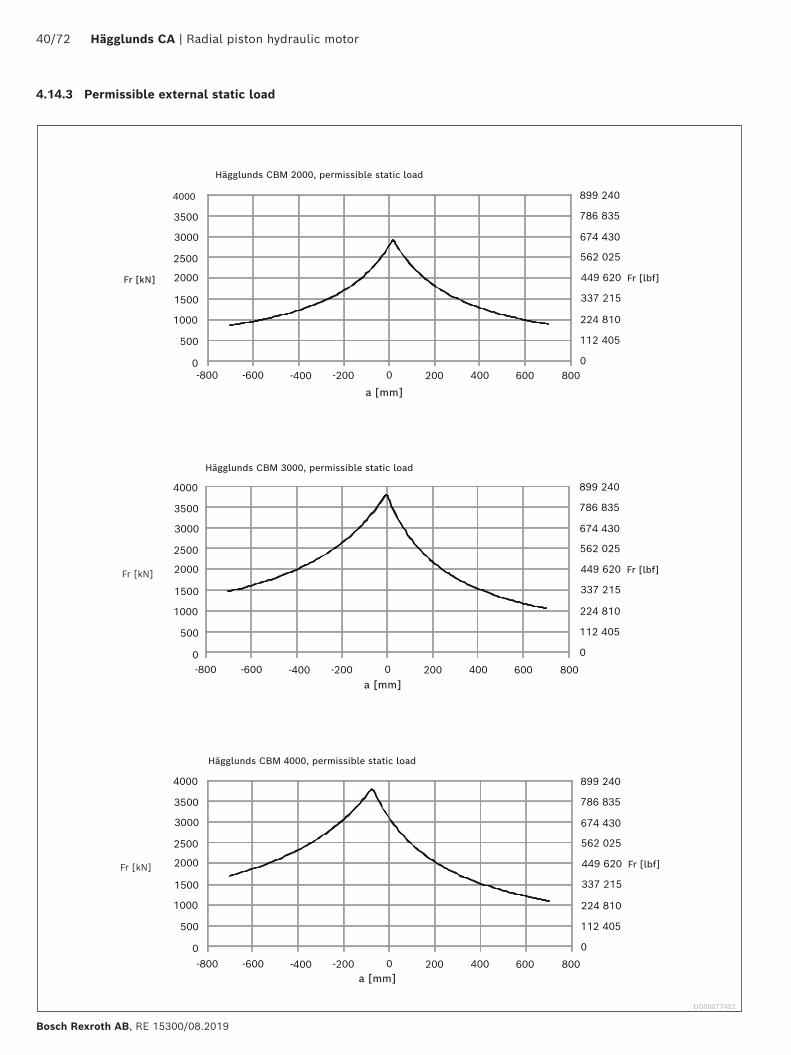
4.14.3 Permissible external static load
DD00077402
Radial piston hydraulic motor | Hägglunds CA 41/72
RE 15300/08.2019, Bosch Rexroth AB
Fr [kN]
4000
3500
2500
1500
3000
2000
1000
500
0
Fr [kN]
4000
3500
2500
1500
3000
2000
1000
500
0
899 240
786 835
674 430
562 025
449 620
337 215
224 810
112 405
0
Fr [lbf]
899 240
786 835
674 430
562 025
449 620
337 215
224 810
112 405
0
Fr [lbf]
-800 -600 -400 -200 200 400 600 8000
a [mm]
-800 -600 -400 -200 200 400 600 8000
a [mm]
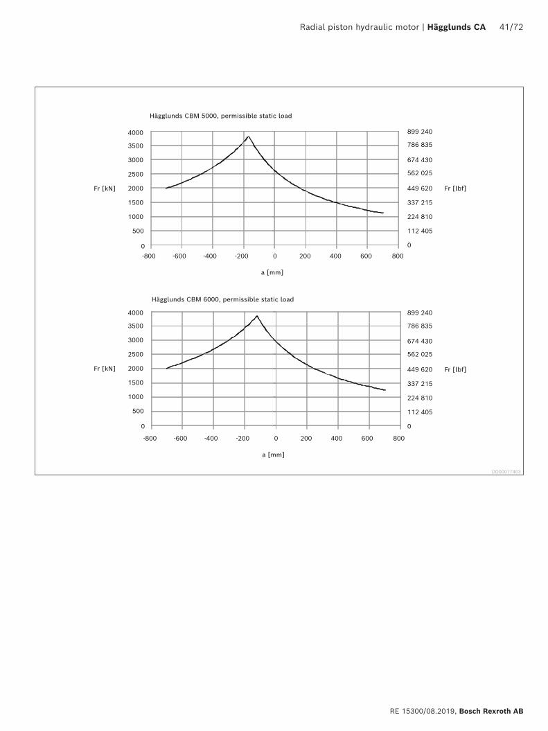
Hägglunds CBM 5000, permissible static load
Hägglunds CBM 6000, permissible static load
DD00077403
42/72 Hägglunds CA | Radial piston hydraulic motor
Bosch Rexroth AB, RE 15300/08.2019
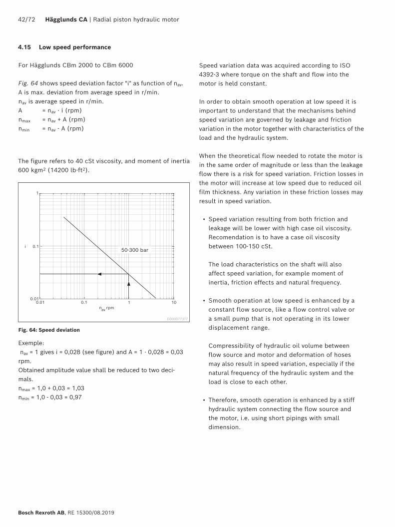
For Hägglunds CBm 2000 to CBm 6000
Fig. 64 shows speed deviation factor "i" as function of nav. A is max. deviation from average speed in r/min. nav is average speed in r/min.A = nav · i (rpm) nmax = nav + A (rpm) nmin = nav - A (rpm)
The figure refers to 40 cSt viscosity, and moment of inertia 600 kgm2 (14200 lb·ft2).
Exemple: nav = 1 gives i = 0,028 (see figure) and A = 1 · 0,028 = 0,03 rpm.Obtained amplitude value shall be reduced to two deci-mals. nmax = 1,0 + 0,03 = 1,03 nmin = 1,0 - 0,03 = 0,97
1
0.1i
0.010.01 0.1 1 10
nav rpm
Speed variation data was acquired according to ISO 4392-3 where torque on the shaft and flow into the motor is held constant.
In order to obtain smooth operation at low speed it is important to understand that the mechanisms behind speed variation are governed by leakage and friction variation in the motor together with characteristics of the load and the hydraulic system.
When the theoretical flow needed to rotate the motor is in the same order of magnitude or less than the leakage flow there is a risk for speed variation. Friction losses in the motor will increase at low speed due to reduced oil film thickness. Any variation in these friction losses may result in speed variation.
• Speed variation resulting from both friction and leakage will be lower with high case oil viscosity. Recomendation is to have a case oil viscosity between 100-150 cSt. The load characteristics on the shaft will also affect speed variation, for example moment of inertia, friction effects and natural frequency.
• Smooth operation at low speed is enhanced by a constant flow source, like a flow control valve or a small pump that is not operating in its lower displacement range. Compressibility of hydraulic oil volume between flow source and motor and deformation of hoses may also result in speed variation, especially if the natural frequency of the hydraulic system and the load is close to each other.
• Therefore, smooth operation is enhanced by a stiff hydraulic system connecting the flow source and the motor, i.e. using short pipings with small dimension.
4.15 Low speed performance
DD00077377
Fig. 64: Speed deviation
50-300 bar
Radial piston hydraulic motor | Hägglunds CA 43/72
RE 15300/08.2019, Bosch Rexroth AB
4.16 Magnetic plug
4.16.1 General
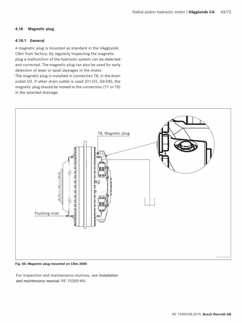
A magnetic plug is mounted as standard in the Hägglunds CBm from factory. By regularly inspecting the magnetic plug a malfunction of the hydraulic system can be detected and corrected. The magnetic plug can also be used for early detection of wear or spall damages in the motor.The magnetic plug is installed in connection T8, in the drain outlet D3. If other drain outlet is used (D1-D2, D4-D8), the magnetic plug should be moved to the connection (T7 or T9) in the selected drainage.
For inspection and maintenance routines, see Installation and maintenance manual: RE 15300-WA.
T8, Magnetic plug
Flushing inlet
Fig. 65: Magnetic plug mounted on CBm 2000
DD00046409
44/72 Hägglunds CA | Radial piston hydraulic motor
Bosch Rexroth AB, RE 15300/08.2019
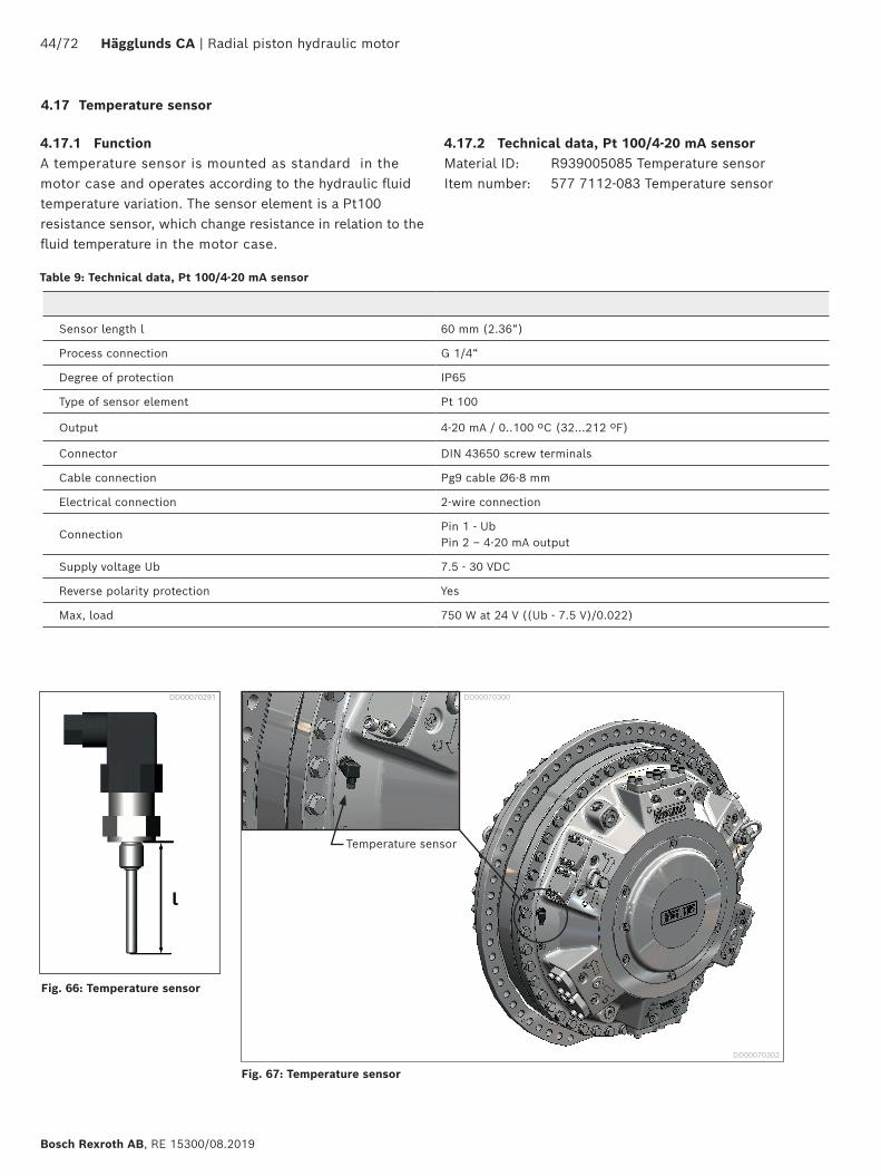
4.17 Temperature sensor
Fig. 66: Temperature sensor
Fig. 67: Temperature sensor
Table 9: Technical data, Pt 100/4-20 mA sensor
DD00070291
4.17.1 FunctionA temperature sensor is mounted as standard in the motor case and operates according to the hydraulic fluid temperature variation. The sensor element is a Pt100 resistance sensor, which change resistance in relation to the fluid temperature in the motor case.
Sensor length l 60 mm (2.36“)
Process connection G 1/4“
Degree of protection IP65
Type of sensor element Pt 100
Output 4-20 mA / 0..100 ºC (32...212 ºF)
Connector DIN 43650 screw terminals
Cable connection Pg9 cable Ø6-8 mm
Electrical connection 2-wire connection
ConnectionPin 1 - Ub Pin 2 – 4-20 mA output
Supply voltage Ub 7.5 - 30 VDC
Reverse polarity protection Yes
Max, load 750 W at 24 V ((Ub - 7.5 V)/0.022)
l
Temperature sensor
DD00070302
DD00070300
4.17.2 Technical data, Pt 100/4-20 mA sensor Material ID: R939005085 Temperature sensorItem number: 577 7112-083 Temperature sensor
Radial piston hydraulic motor | Hägglunds CA 45/72
RE 15300/08.2019, Bosch Rexroth AB
4.18 Painting system
Corrosion protection
The painting system of Hägglunds motors and accessories are avalible in two different corrosivity categories regarding corrosion protection in accordance with SS-EN ISO 12944:
• C3 - Corrosivity category Medium - which is recom-mended for normal urban and industrial atmosphere.
• C5M - Corrosivity category Very High - which is recommended for marine environment with high salt load or other aggressive atmosphere.
ColourStandard colour for Hägglunds motors and accessories is orange (RAL 2002)
5 Type of seal
Option N:
NBR (Nitrile) Preferd alternative at low ambient tempera-tures and moderate case oil temperatures.See section 4.2: General data
Option V:
FPM (Viton) Preferd alternative at higher case oil tempera-tures and freewheeling at higher speed or operating with fire resistant fluids. See section 4.2: General data, 4.13.4: Power loss freewheeling and Data sheet RE 15414
6 Increased robustness
Option A:
CBm has DLC-coated pistons and piston rings as standard.That give no limitation for low speed even down to 0,03 rpm at maximum pressure.
Option C:
DLC-coated cam rollers in combination with coated pistons and piston rings is recommended to be used in the follow-ing cases: - When replacing an existing MB-motor with a CBm-motor and operating parameters (eg. viscosity) are unclear- If there is a risk for cavitation in combination with shock loads- If oil viscosities is below 20 cSt in motor case
46/72 Hägglunds CA | Radial piston hydraulic motor
Bosch Rexroth AB, RE 15300/08.2019
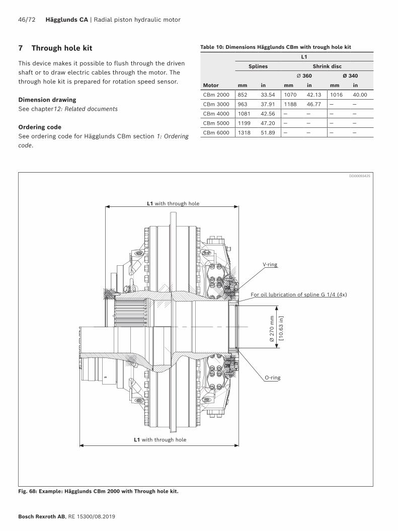
Fig. 68: Example: Hägglunds CBm 2000 with Through hole kit.
7 Through hole kit
This device makes it possible to flush through the driven shaft or to draw electric cables through the motor. The through hole kit is prepared for rotation speed sensor.
Dimension drawingSee chapter12: Related documents
Ordering codeSee ordering code for Hägglunds CBm section 1: Ordering code.
Ø 2
70 m
mV-ring
O-ring
For oil lubrication of spline G 1/4 (4x)
L1 with through hole
Table 10: Dimensions Hägglunds CBm with trough hole kit
L1
Splines Shrink disc
Ø 360 Ø 340
Motor mm in mm in mm in
CBm 2000 852 33.54 1070 42.13 1016 40.00
CBm 3000 963 37.91 1188 46.77 — —
CBm 4000 1081 42.56 — — — —
CBm 5000 1199 47.20 — — — —
CBm 6000 1318 51.89 — — — —
DD00093425
[10.
63 in
]
L1 with through hole
Radial piston hydraulic motor | Hägglunds CA 47/72
RE 15300/08.2019, Bosch Rexroth AB
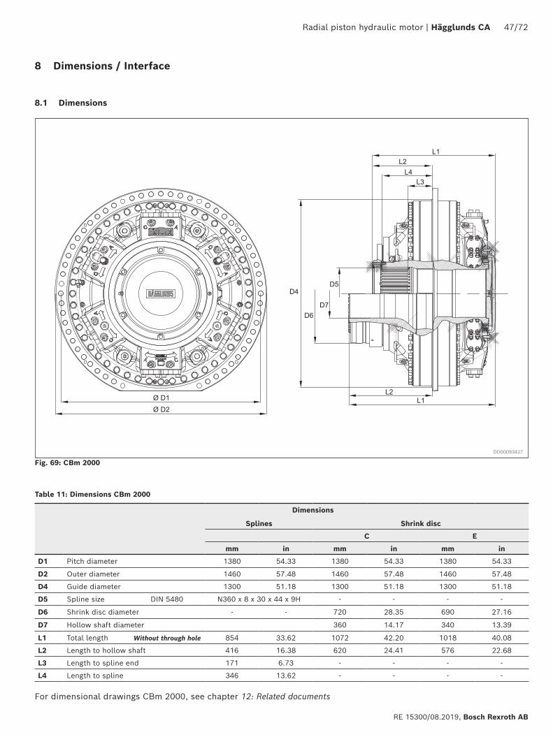
Fig. 69: CBm 2000
For dimensional drawings CBm 2000, see chapter 12: Related documents
Dimensions
Splines Shrink disc
C E
mm in mm in mm in
D1 Pitch diameter 1380 54.33 1380 54.33 1380 54.33
D2 Outer diameter 1460 57.48 1460 57.48 1460 57.48
D4 Guide diameter 1300 51.18 1300 51.18 1300 51.18
D5 Spline size DIN 5480 N360 x 8 x 30 x 44 x 9H - - - -
D6 Shrink disc diameter - - 720 28.35 690 27.16
D7 Hollow shaft diameter 360 14.17 340 13.39
L1 Total length Without through hole 854 33.62 1072 42.20 1018 40.08
L2 Length to hollow shaft 416 16.38 620 24.41 576 22.68
L3 Length to spline end 171 6.73 - - - -
L4 Length to spline 346 13.62 - - - -
Table 11: Dimensions CBm 2000
8 Dimensions / Interface
8.1 Dimensions
DD00093427
48/72 Hägglunds CA | Radial piston hydraulic motor
Bosch Rexroth AB, RE 15300/08.2019
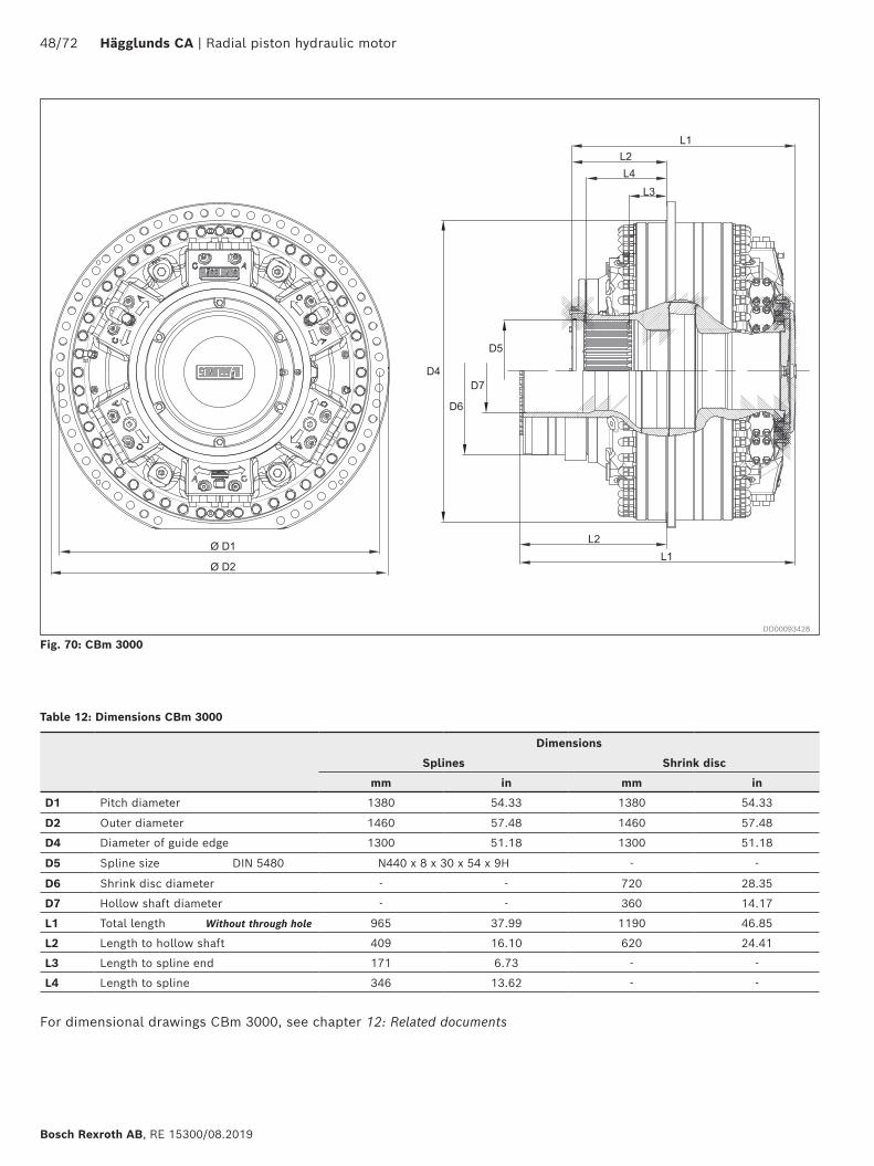
Fig. 70: CBm 3000
Dimensions
Splines Shrink disc
mm in mm in
D1 Pitch diameter 1380 54.33 1380 54.33
D2 Outer diameter 1460 57.48 1460 57.48
D4 Diameter of guide edge 1300 51.18 1300 51.18
D5 Spline size DIN 5480 N440 x 8 x 30 x 54 x 9H - -
D6 Shrink disc diameter - - 720 28.35
D7 Hollow shaft diameter - - 360 14.17
L1 Total length Without through hole 965 37.99 1190 46.85
L2 Length to hollow shaft 409 16.10 620 24.41
L3 Length to spline end 171 6.73 - -
L4 Length to spline 346 13.62 - -
Table 12: Dimensions CBm 3000
For dimensional drawings CBm 3000, see chapter 12: Related documents
DD00093428
Radial piston hydraulic motor | Hägglunds CA 49/72
RE 15300/08.2019, Bosch Rexroth AB
Ø D1
Ø D2
L3L4
L2
L1
D5D4
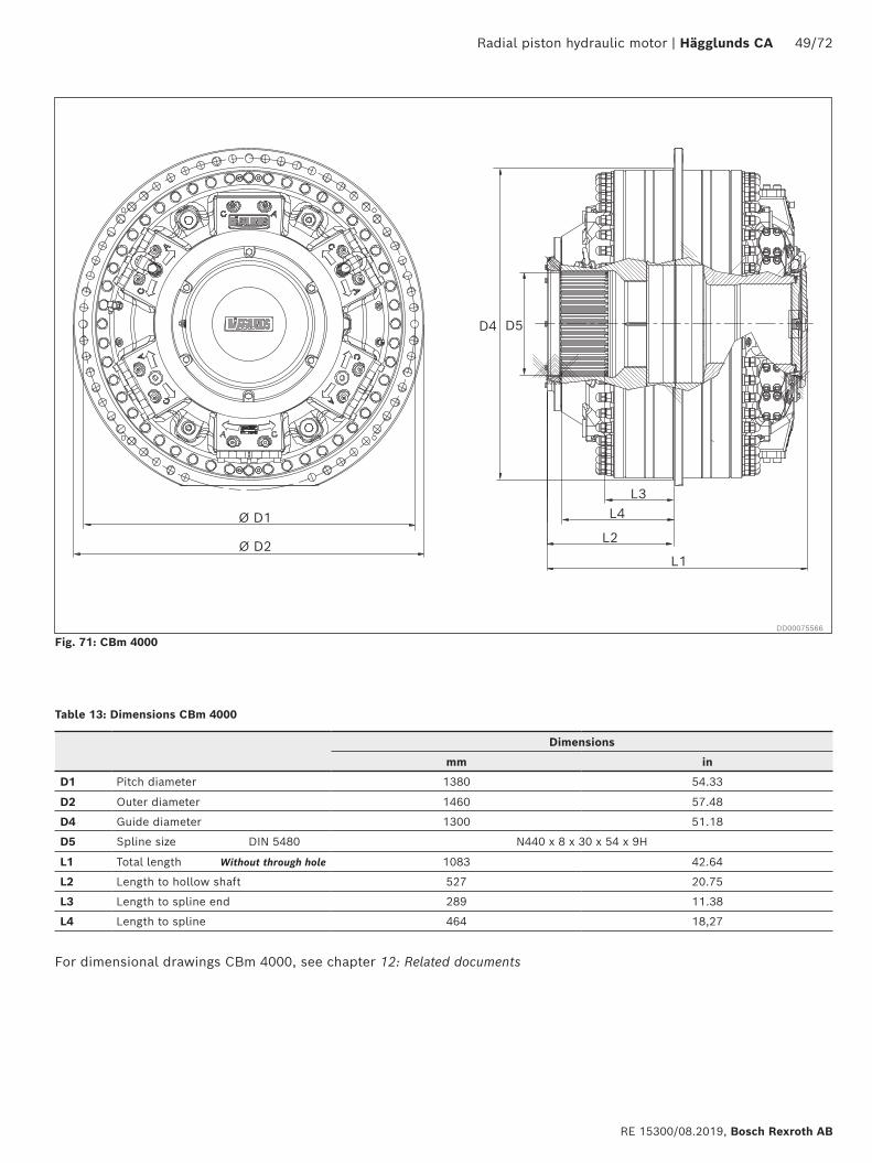
Fig. 71: CBm 4000
Table 13: Dimensions CBm 4000
Dimensions
mm in
D1 Pitch diameter 1380 54.33
D2 Outer diameter 1460 57.48
D4 Guide diameter 1300 51.18
D5 Spline size DIN 5480 N440 x 8 x 30 x 54 x 9H
L1 Total length Without through hole 1083 42.64
L2 Length to hollow shaft 527 20.75
L3 Length to spline end 289 11.38
L4 Length to spline 464 18,27
DD00075566
For dimensional drawings CBm 4000, see chapter 12: Related documents
50/72 Hägglunds CA | Radial piston hydraulic motor
Bosch Rexroth AB, RE 15300/08.2019
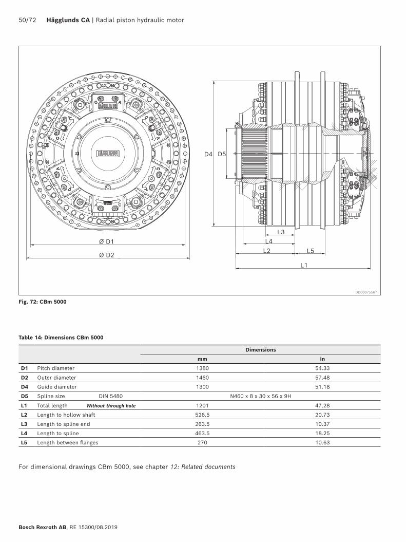
Fig. 72: CBm 5000
Dimensions
mm in
D1 Pitch diameter 1380 54.33
D2 Outer diameter 1460 57.48
D4 Guide diameter 1300 51.18
D5 Spline size DIN 5480 N460 x 8 x 30 x 56 x 9H
L1 Total length Without through hole 1201 47.28
L2 Length to hollow shaft 526.5 20.73
L3 Length to spline end 263.5 10.37
L4 Length to spline 463.5 18.25
L5 Length between flanges 270 10.63
Table 14: Dimensions CBm 5000
Ø D1
Ø D2
L3L4
L2
L1
D5D4
L5
DD00075567
For dimensional drawings CBm 5000, see chapter 12: Related documents
Radial piston hydraulic motor | Hägglunds CA 51/72
RE 15300/08.2019, Bosch Rexroth AB
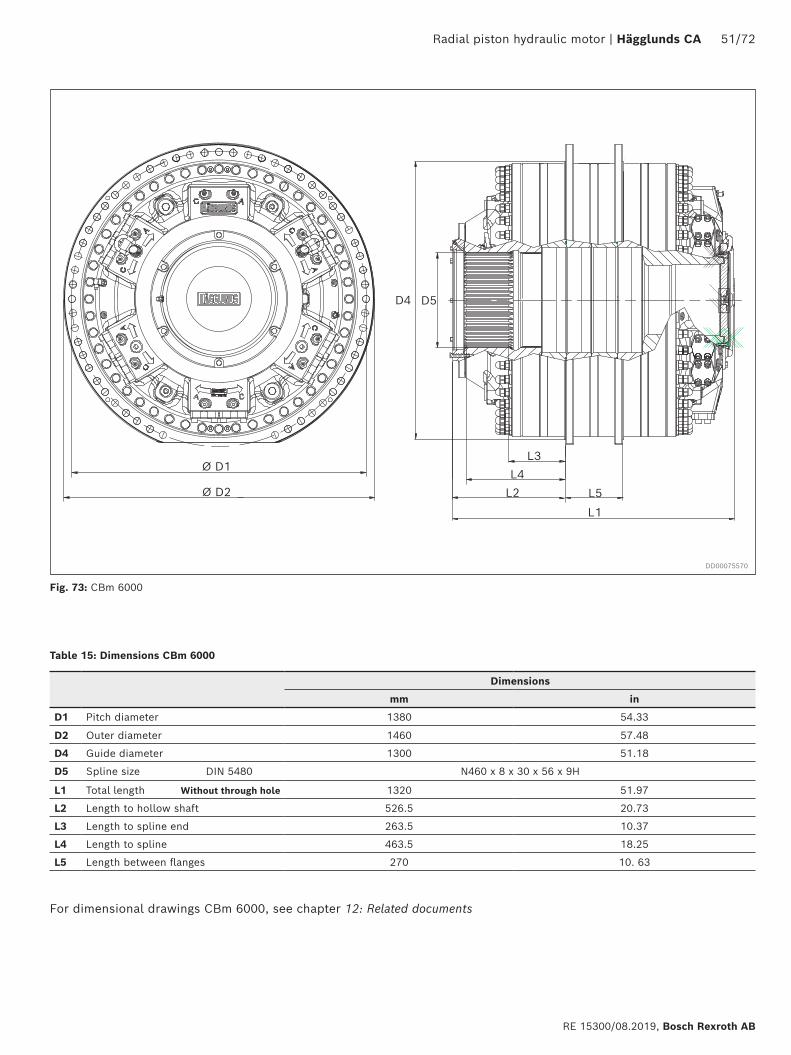
Fig. 73: CBm 6000
Table 15: Dimensions CBm 6000
Ø D1
Ø D2
D5D4
L3L4
L2 L5
L1
Dimensions
mm in
D1 Pitch diameter 1380 54.33
D2 Outer diameter 1460 57.48
D4 Guide diameter 1300 51.18
D5 Spline size DIN 5480 N460 x 8 x 30 x 56 x 9H
L1 Total length Without through hole 1320 51.97
L2 Length to hollow shaft 526.5 20.73
L3 Length to spline end 263.5 10.37
L4 Length to spline 463.5 18.25
L5 Length between flanges 270 10. 63
DD00075570
For dimensional drawings CBm 6000, see chapter 12: Related documents
52/72 Hägglunds CA | Radial piston hydraulic motor
Bosch Rexroth AB, RE 15300/08.2019
9 Mounting alternatives
9.1 General information
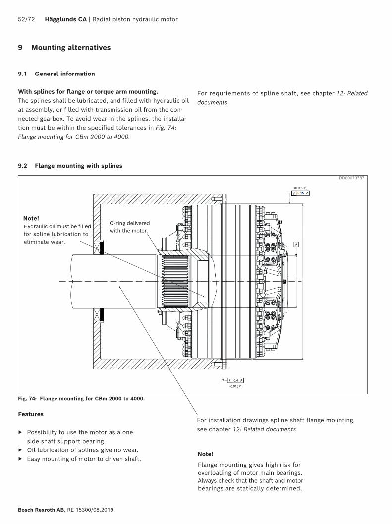
With splines for flange or torque arm mounting.The splines shall be lubricated, and filled with hydraulic oil at assembly, or filled with transmission oil from the con-nected gearbox. To avoid wear in the splines, the installa-tion must be within the specified tolerances in Fig. 74: Flange mounting for CBm 2000 to 4000.
For requriements of spline shaft, see chapter 12: Related documents
0.4 A
(0.0157”)
(0.0591”)
Fig. 74: Flange mounting for CBm 2000 to 4000.
Features
▶ Possibility to use the motor as a one side shaft support bearing.
▶ Oil lubrication of splines give no wear. ▶ Easy mounting of motor to driven shaft.
DD00073787
For installation drawings spline shaft flange mounting, see chapter 12: Related documents
O-ring delivered with the motor.
Hydraulic oil must be filled for spline lubrication to eliminate wear.
Note!
Flange mounting gives high risk for overloading of motor main bearings. Always check that the shaft and motor bearings are statically determined.
Note!
9.2 Flange mounting with splines
Radial piston hydraulic motor | Hägglunds CA 53/72
RE 15300/08.2019, Bosch Rexroth AB
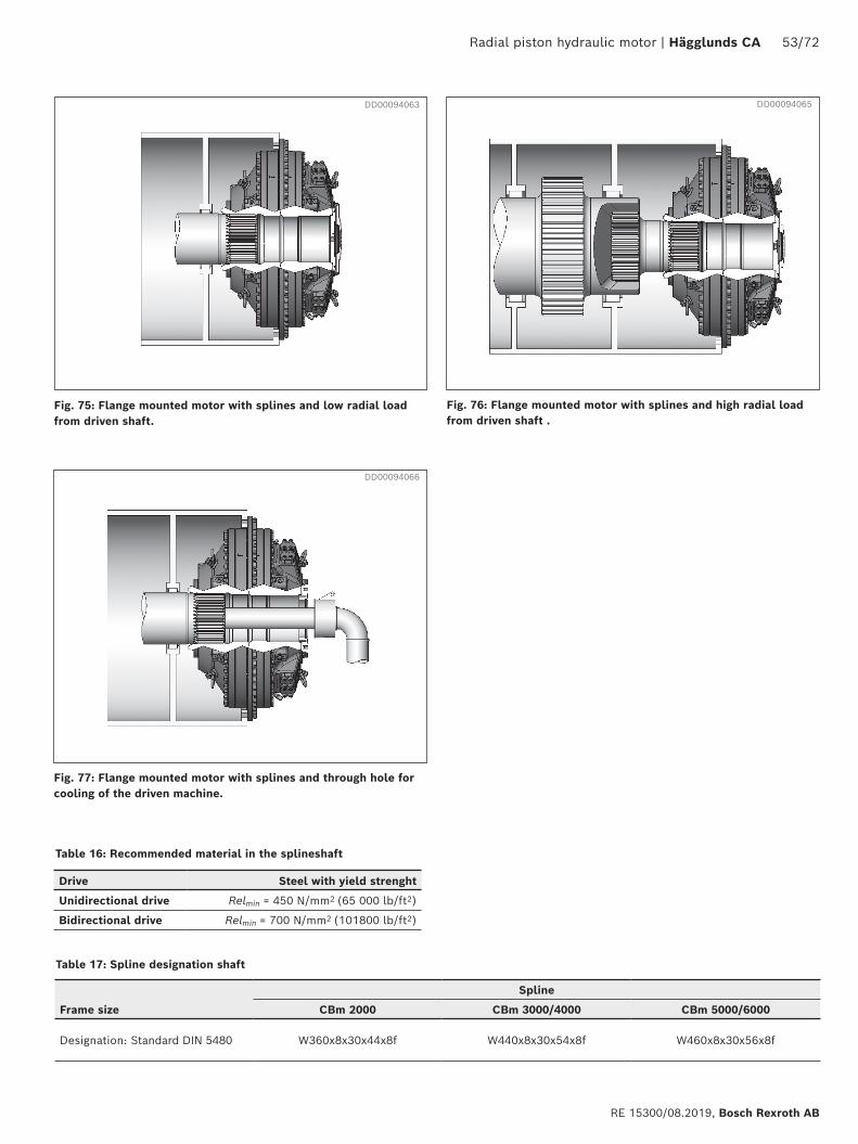
Table 16: Recommended material in the splineshaft
Drive Steel with yield strenght
Unidirectional drive Relmin = 450 N/mm2 (65 000 lb/ft2)
Bidirectional drive Relmin = 700 N/mm2 (101800 lb/ft2)
Table 17: Spline designation shaft
Spline
Frame size CBm 2000 CBm 3000/4000 CBm 5000/6000
Designation: Standard DIN 5480 W360x8x30x44x8f W440x8x30x54x8f W460x8x30x56x8f
Fig. 75: Flange mounted motor with splines and low radial load from driven shaft.
Fig. 76: Flange mounted motor with splines and high radial load from driven shaft .
Fig. 77: Flange mounted motor with splines and through hole for cooling of the driven machine.
DD00094063 DD00094065
DD00094066
54/72 Hägglunds CA | Radial piston hydraulic motor
Bosch Rexroth AB, RE 15300/08.2019
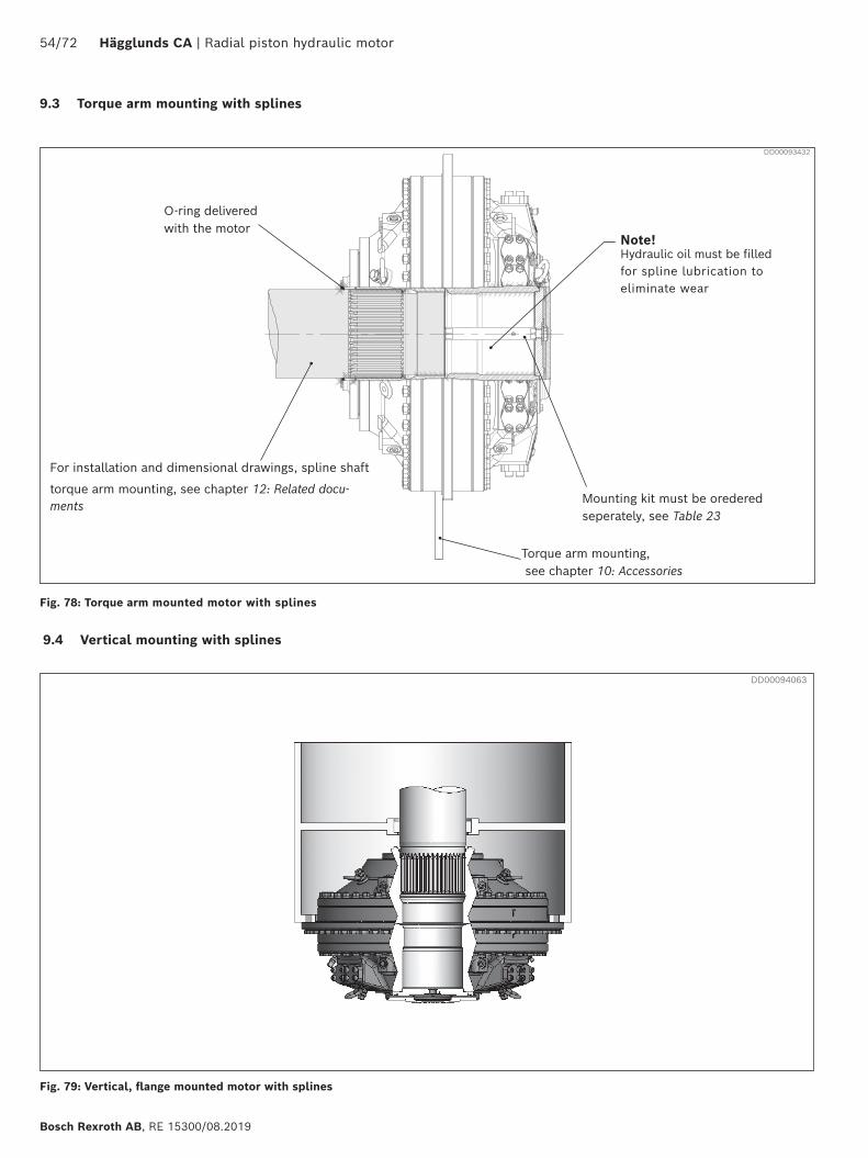
9.4 Vertical mounting with splines
DD00093432
For installation and dimensional drawings, spline shaft
torque arm mounting, see chapter 12: Related docu-ments Mounting kit must be oredered
seperately, see Table 23
Torque arm mounting, see chapter 10: Accessories
O-ring delivered with the motor
Note! Hydraulic oil must be filled for spline lubrication to eliminate wear
Fig. 78: Torque arm mounted motor with splines
9.3 Torque arm mounting with splines
Fig. 79: Vertical, flange mounted motor with splines
DD00094063
55/72 Hägglunds CA | Radial piston hydraulic motor
Bosch Rexroth AB, RE 15300/08.2019
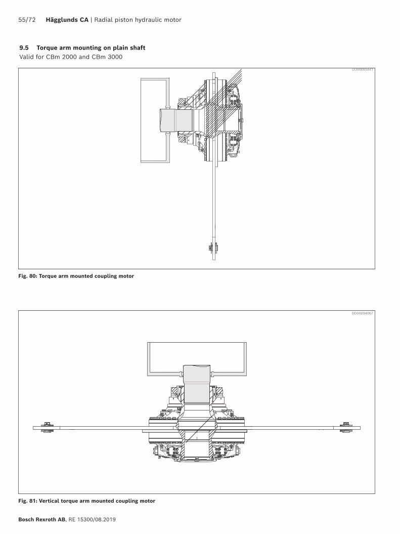
9.5 Torque arm mounting on plain shaft Valid for CBm 2000 and CBm 3000
Fig. 80: Torque arm mounted coupling motor
Fig. 81: Vertical torque arm mounted coupling motor
DD00093441
DD00094067
Radial piston hydraulic motor | Hägglunds CA 56/72
RE 15300/08.2019, Bosch Rexroth AB
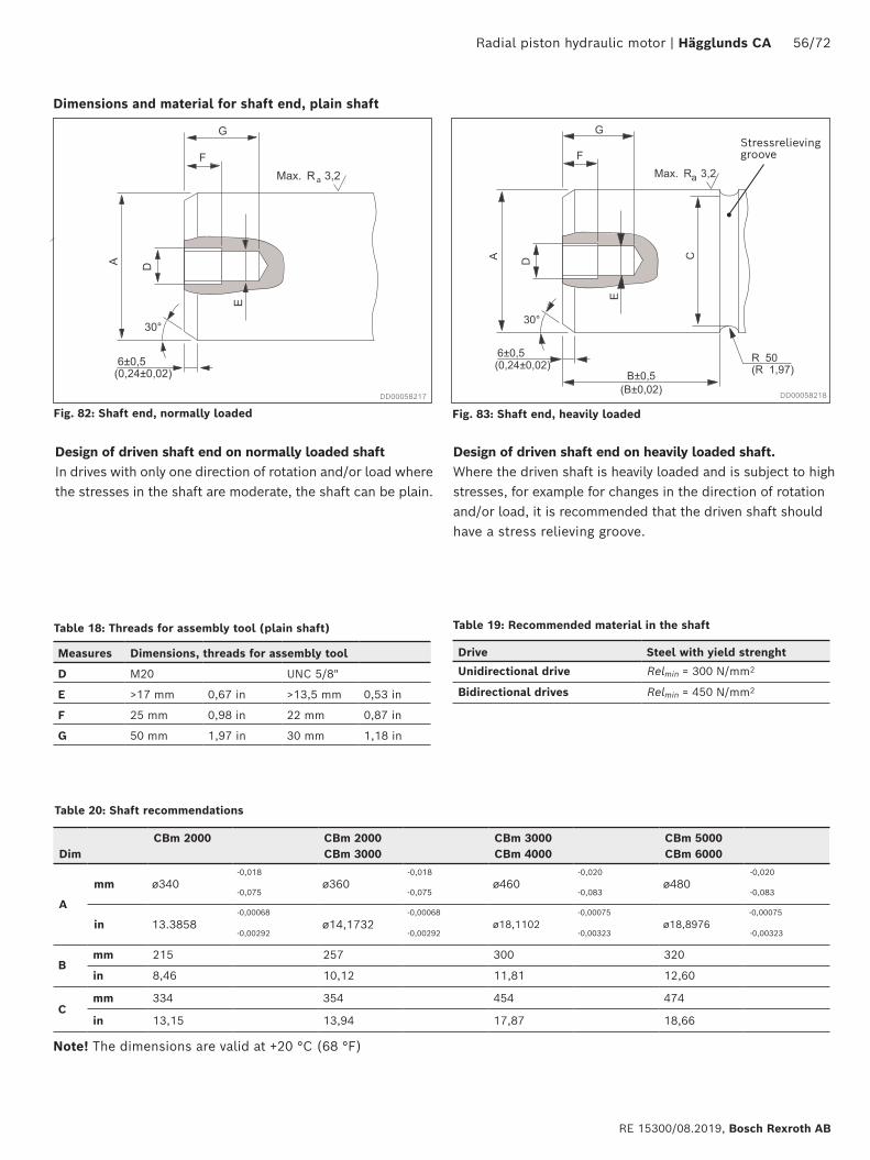
Dimensions and material for shaft end, plain shaft
Design of driven shaft end on normally loaded shaftIn drives with only one direction of rotation and/or load where the stresses in the shaft are moderate, the shaft can be plain.
Design of driven shaft end on heavily loaded shaft.Where the driven shaft is heavily loaded and is subject to high stresses, for example for changes in the direction of rotation and/or load, it is recommended that the driven shaft should have a stress relieving groove.
Table 18: Threads for assembly tool (plain shaft)
DimCBm 2000 CBm 2000
CBm 3000 CBm 3000CBm 4000
CBm 5000CBm 6000
A
mm ø340-0,018
ø360-0,018
ø460-0,020
ø480-0,020
-0,075 -0,075 -0,083 -0,083
in 13.3858-0,00068
ø14,1732-0,00068
ø18,1102-0,00075
ø18,8976-0,00075
-0,00292 -0,00292 -0,00323 -0,00323
Bmm 215 257 300 320
in 8,46 10,12 11,81 12,60
Cmm 334 354 454 474
in 13,15 13,94 17,87 18,66
Fig. 83: Shaft end, heavily loaded
Note! The dimensions are valid at +20 °C (68 °F)
Stressrelieving groove
Measures Dimensions, threads for assembly tool
D M20 UNC 5/8"
E >17 mm 0,67 in >13,5 mm 0,53 in
F 25 mm 0,98 in 22 mm 0,87 in
G 50 mm 1,97 in 30 mm 1,18 in
Drive Steel with yield strenght
Unidirectional drive Relmin = 300 N/mm2
Bidirectional drives Relmin = 450 N/mm2
Table 19: Recommended material in the shaft
Fig. 82: Shaft end, normally loaded
DD00058217 DD00058218
Table 20: Shaft recommendations
Radial piston hydraulic motor | Hägglunds CA 57/72
RE 15300/08.2019, Bosch Rexroth AB
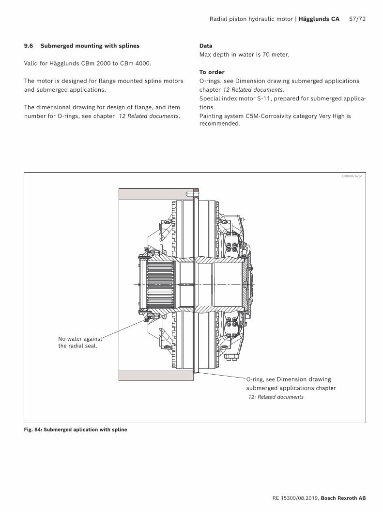
9.6 Submerged mounting with splines
Valid for Hägglunds CBm 2000 to CBm 4000.
The motor is designed for flange mounted spline motors and submerged applications.
The dimensional drawing for design of flange, and item number for O-rings, see chapter 12 Related documents.
No water against the radial seal.
O-ring, see Dimension drawing submerged applications chapter
12: Related documents
DD00076761
Fig. 84: Submerged aplication with spline
DataMax depth in water is 70 meter.
To orderO-rings, see Dimension drawing submerged applications chapter 12 Related documents.Special index motor S-11, prepared for submerged applica-tions. Painting system C5M-Corrosivity category Very High is recommended.
58/72 Hägglunds CA | Radial piston hydraulic motor
Bosch Rexroth AB, RE 15300/08.2019
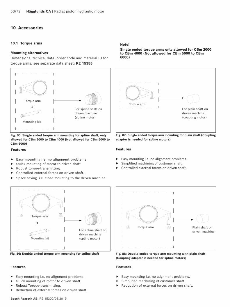
10 Accessories
10.1 Torque arms
Mounting alternatives Dimensions, techical data, order code and material ID for torque arms, see separate data sheet: RE 15355
Fig. 85: Single ended torque arm mounting for spline shaft, only allowed for CBm 2000 to CBm 4000 (Not allowed for CBm 5000 to CBm 6000)
+ For spline shaft on driven machine(spline motor)
Mounting kit
Torque arm
Features
▶ Easy mounting i.e. no alignment problems. ▶ Quick mounting of motor to driven shaft ▶ Robust torque-transmitting. ▶ Controlled external forces on driven shaft. ▶ Space saving. i.e. close mounting to the driven machine.
Features
▶ Easy mounting i.e. no alignment problems. ▶ Quick mounting of motor to driven shaft ▶ Robust Torque-transmitting. ▶ Reduction of external forces on driven shaft.
+
Fig. 86: Double ended torque arm mounting for spline shaft
Mounting kit
Torque arm
For spline shaft on driven machine(spline motor)
Features
▶ Easy mounting i.e. no alignment problems. ▶ Simplified machining of customer shaft. ▶ Controlled external forces on driven shaft.
Features
▶ Easy mounting i.e. no alignment problems. ▶ Simplified machining of customer shaft. ▶ Reduction of external forces on driven shaft.
Fig. 87: Single ended torque arm mounting for plain shaft (Coupling adapter is needed for spline motors)
For plain shaft on driven machine(coupling motor)
Plain shaft on driven machine
Fig. 88: Double ended torque arm mounting with plain shaft (Coupling adapter is needed for spline motors)
Torque arm
Torque arm
Note!Single ended torque arms only allowed for CBm 2000 to CBm 4000 (Not allowed for CBm 5000 to CBm 6000)
Radial piston hydraulic motor | Hägglunds CA 59/72
RE 15300/08.2019, Bosch Rexroth AB
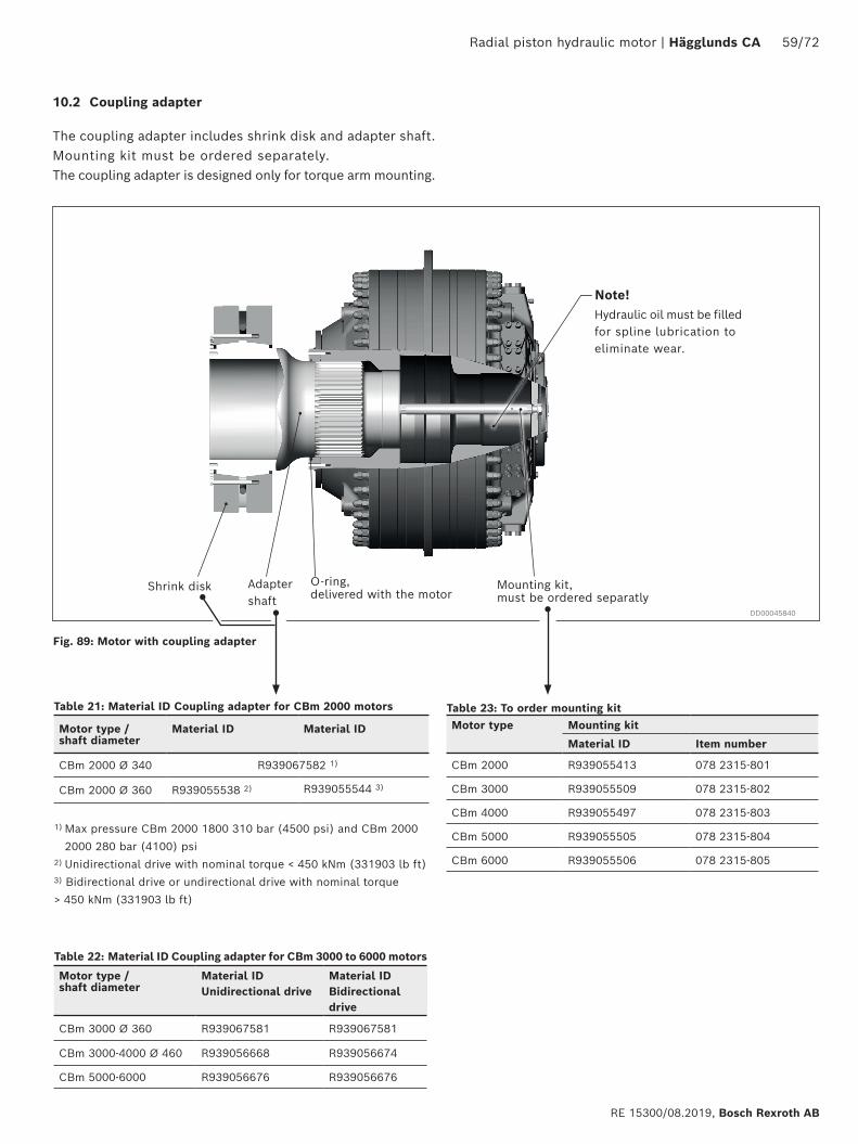
10.2 Coupling adapter
The coupling adapter includes shrink disk and adapter shaft. Mounting kit must be ordered separately. The coupling adapter is designed only for torque arm mounting.
Shrink disk O-ring, delivered with the motor
Adapter shaft
Mounting kit, must be ordered separatly
Hydraulic oil must be filled for spline lubrication to eliminate wear.
Motor type Mounting kit
Material ID Item number
CBm 2000 R939055413 078 2315-801
CBm 3000 R939055509 078 2315-802
CBm 4000 R939055497 078 2315-803
CBm 5000 R939055505 078 2315-804
CBm 6000 R939055506 078 2315-805
Fig. 89: Motor with coupling adapter
Note!
DD00045840
Motor type /shaft diameter
Material ID Material ID
CBm 2000 Ø 340 R939067582 1)
CBm 2000 Ø 360 R939055538 2) R939055544 3)
1) Max pressure CBm 2000 1800 310 bar (4500 psi) and CBm 2000 2000 280 bar (4100) psi2) Unidirectional drive with nominal torque < 450 kNm (331903 lb ft)3) Bidirectional drive or undirectional drive with nominal torque > 450 kNm (331903 lb ft)
Motor type /shaft diameter
Material IDUnidirectional drive
Material IDBidirectional drive
CBm 3000 Ø 360 R939067581 R939067581
CBm 3000-4000 Ø 460 R939056668 R939056674
CBm 5000-6000 R939056676 R939056676
Table 21: Material ID Coupling adapter for CBm 2000 motors
Table 22: Material ID Coupling adapter for CBm 3000 to 6000 motors
Table 23: To order mounting kit
60/72 Hägglunds CA | Radial piston hydraulic motor
Bosch Rexroth AB, RE 15300/08.2019
A B
F
D
C
Rotat-ing part
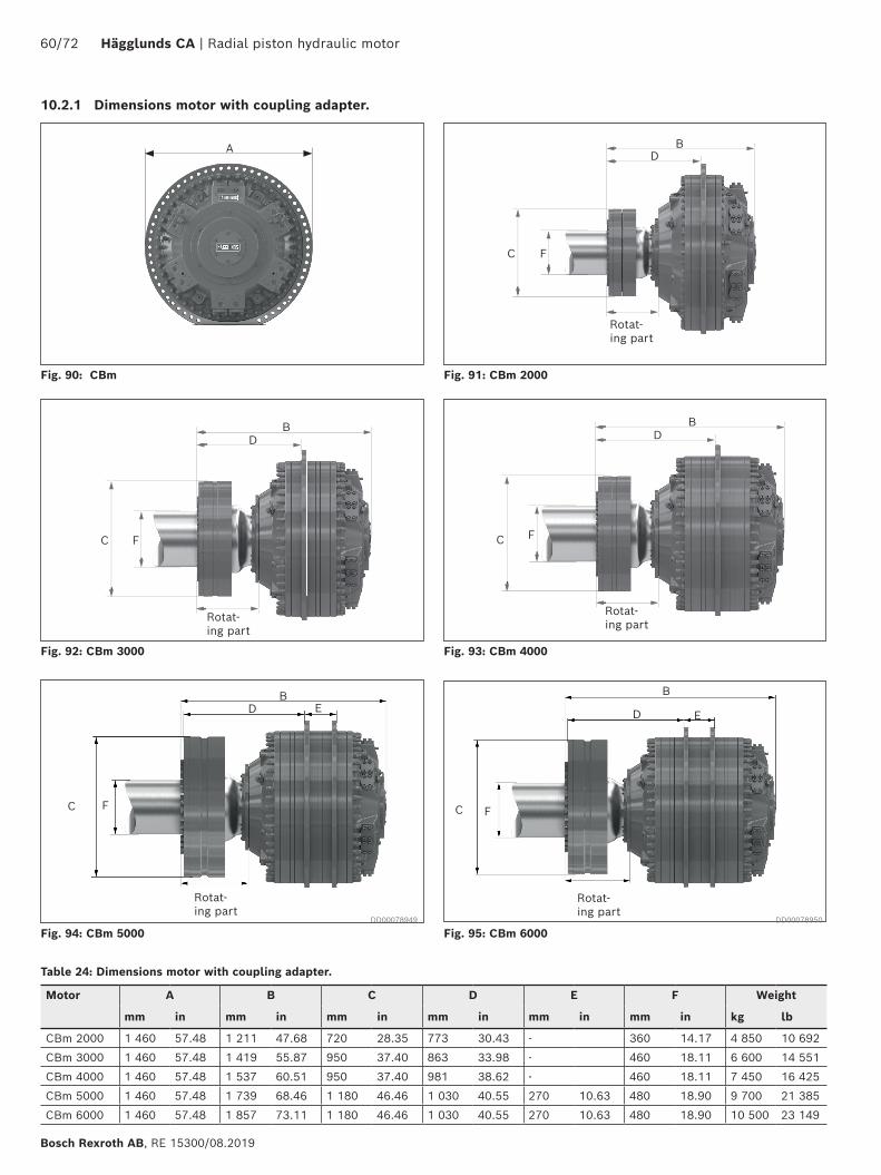
Fig. 90: CBm Fig. 91: CBm 2000
Fig. 92: CBm 3000 Fig. 93: CBm 4000
Fig. 94: CBm 5000 Fig. 95: CBm 6000
B B
B
D D
D
FC FC
FC
Rotat-ing part
Rotat-ing part
Rotat-ing part
E
Table 24: Dimensions motor with coupling adapter.
10.2.1 Dimensions motor with coupling adapter.
Motor A B C D E F Weight
mm in mm in mm in mm in mm in mm in kg lb
CBm 2000 1 460 57.48 1 211 47.68 720 28.35 773 30.43 - 360 14.17 4 850 10 692
CBm 3000 1 460 57.48 1 419 55.87 950 37.40 863 33.98 - 460 18.11 6 600 14 551
CBm 4000 1 460 57.48 1 537 60.51 950 37.40 981 38.62 - 460 18.11 7 450 16 425
CBm 5000 1 460 57.48 1 739 68.46 1 180 46.46 1 030 40.55 270 10.63 480 18.90 9 700 21 385
CBm 6000 1 460 57.48 1 857 73.11 1 180 46.46 1 030 40.55 270 10.63 480 18.90 10 500 23 149
Rotat-ing part
C F
DB
E
DD00078949 DD00078950
Radial piston hydraulic motor | Hägglunds CA 61/72
RE 15300/08.2019, Bosch Rexroth AB
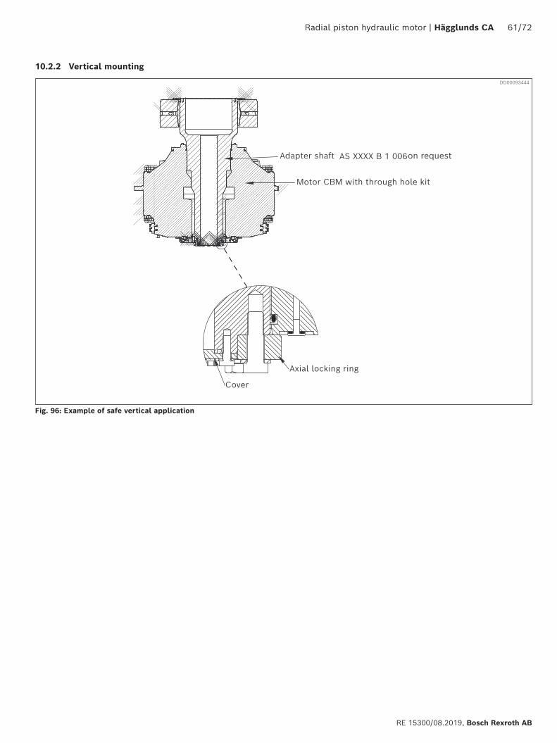
10.2.2 Vertical mounting
Motor CBM with through hole kit
Axial locking ring
Cover
Adapter shaft AS XXXX B 1 006
Fig. 96: Example of safe vertical application
on request
DD00093444
62/72 Hägglunds CA | Radial piston hydraulic motor
Bosch Rexroth AB, RE 15300/08.2019
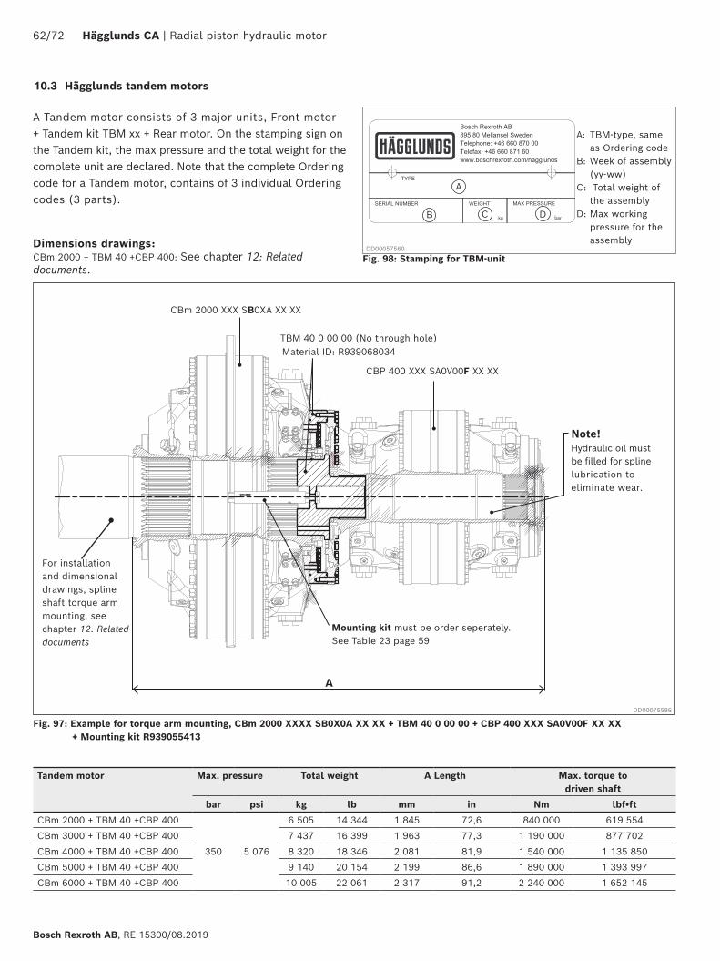
10.3 Hägglunds tandem motors
Fig. 97: Example for torque arm mounting, CBm 2000 XXXX SB0X0A XX XX + TBM 40 0 00 00 + CBP 400 XXX SA0V00F XX XX + Mounting kit R939055413
Fig. 98: Stamping for TBM-unit
A: TBM-type, same as Ordering code
B: Week of assembly (yy-ww)
C: Total weight of the assembly
D: Max working pressure for the assembly
Tandem motor Max. pressure Total weight A Length Max. torque to driven shaft
bar psi kg lb mm in Nm lbf•ft
CBm 2000 + TBM 40 +CBP 400
350 5 076
6 505 14 344 1 845 72,6 840 000 619 554
CBm 3000 + TBM 40 +CBP 400 7 437 16 399 1 963 77,3 1 190 000 877 702
CBm 4000 + TBM 40 +CBP 400 8 320 18 346 2 081 81,9 1 540 000 1 135 850
CBm 5000 + TBM 40 +CBP 400 9 140 20 154 2 199 86,6 1 890 000 1 393 997
CBm 6000 + TBM 40 +CBP 400 10 005 22 061 2 317 91,2 2 240 000 1 652 145
A Tandem motor consists of 3 major units, Front motor + Tandem kit TBM xx + Rear motor. On the stamping sign on the Tandem kit, the max pressure and the total weight for the complete unit are declared. Note that the complete Ordering code for a Tandem motor, contains of 3 individual Ordering codes (3 parts).
Dimensions drawings:CBm 2000 + TBM 40 +CBP 400: See chapter 12: Related documents.
A
CBm 2000 XXX SB0XA XX XX
CBP 400 XXX SA0V00F XX XX
Mounting kit must be order seperately.See Table 23 page 59
TBM 40 0 00 00 (No through hole)Material ID: R939068034
Hydraulic oil must be filled for spline lubrication to eliminate wear.
Note!
DD00075586
A
B C D
For installation and dimensional drawings, spline shaft torque arm mounting, see chapter 12: Related documents
DD00057560
Radial piston hydraulic motor | Hägglunds CA 63/72
RE 15300/08.2019, Bosch Rexroth AB
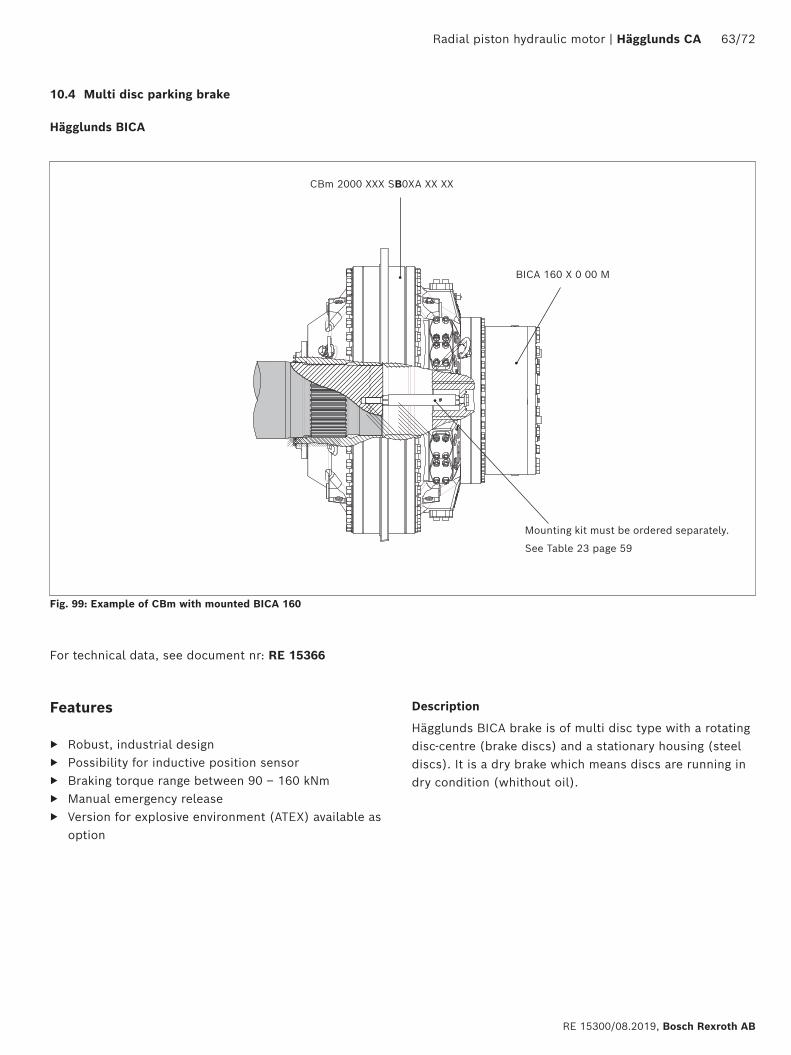
10.4 Multi disc parking brake
Hägglunds BICA
Fig. 99: Example of CBm with mounted BICA 160
CBm 2000 XXX SB0XA XX XX
BICA 160 X 0 00 M
For technical data, see document nr: RE 15366
Features
▶ Robust, industrial design ▶ Possibility for inductive position sensor ▶ Braking torque range between 90 – 160 kNm ▶ Manual emergency release ▶ Version for explosive environment (ATEX) available as
option
Description
Hägglunds BICA brake is of multi disc type with a rotating disc-centre (brake discs) and a stationary housing (steel discs). It is a dry brake which means discs are running in dry condition (whithout oil).
Mounting kit must be ordered separately.
See Table 23 page 59
64/72 Hägglunds CA | Radial piston hydraulic motor
Bosch Rexroth AB, RE 15300/08.2019
10.5 Speed sensor
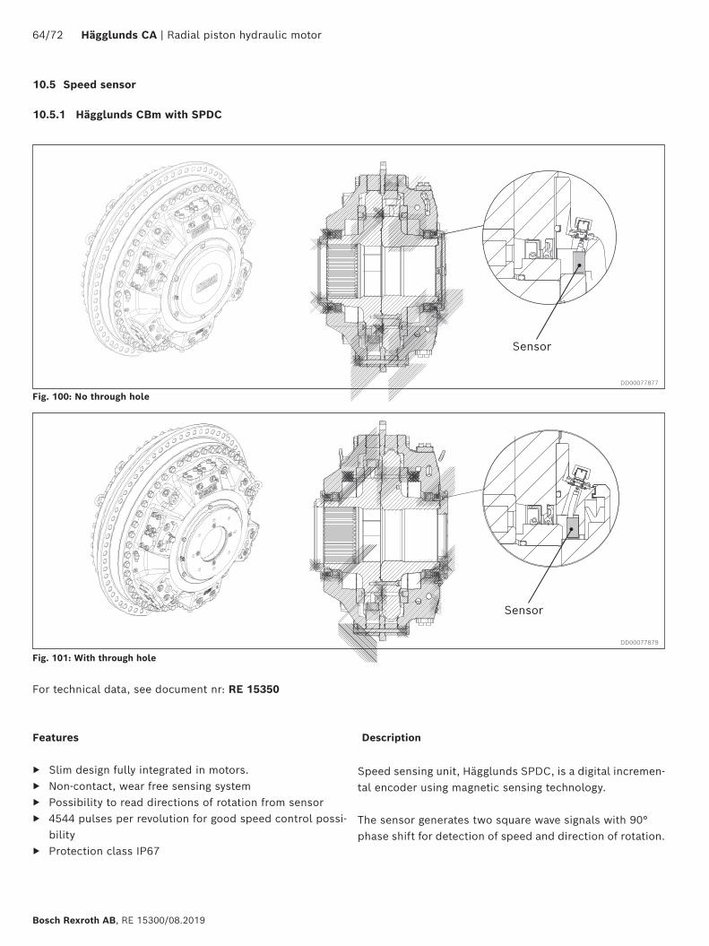
10.5.1 Hägglunds CBm with SPDC
Speed sensing unit, Hägglunds SPDC, is a digital incremen-tal encoder using magnetic sensing technology.
The sensor generates two square wave signals with 90° phase shift for detection of speed and direction of rotation.
Features
▶ Slim design fully integrated in motors. ▶ Non-contact, wear free sensing system ▶ Possibility to read directions of rotation from sensor ▶ 4544 pulses per revolution for good speed control possi-
bility ▶ Protection class IP67
For technical data, see document nr: RE 15350
Fig. 100: No through hole
Fig. 101: With through hole
Description
DD00077877
DD00077879
Sensor
Sensor
Radial piston hydraulic motor | Hägglunds CA 65/72
RE 15300/08.2019, Bosch Rexroth AB
DD00077362
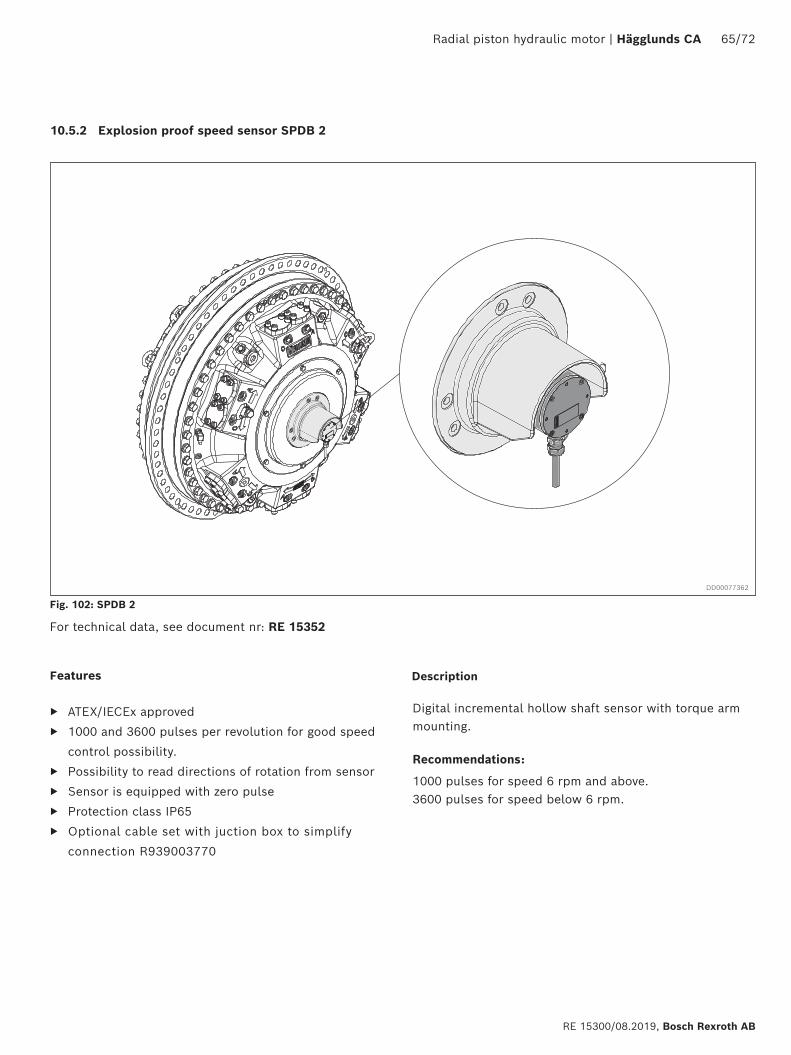
10.5.2 Explosion proof speed sensor SPDB 2
Digital incremental hollow shaft sensor with torque arm mounting.
Recommendations:
1000 pulses for speed 6 rpm and above. 3600 pulses for speed below 6 rpm.
Fig. 102: SPDB 2
Features
▶ ATEX/IECEx approved
▶ 1000 and 3600 pulses per revolution for good speed
control possibility.
▶ Possibility to read directions of rotation from sensor
▶ Sensor is equipped with zero pulse
▶ Protection class IP65
▶ Optional cable set with juction box to simplify
connection R939003770
For technical data, see document nr: RE 15352
Description
66/72 Hägglunds CA | Radial piston hydraulic motor
Bosch Rexroth AB, RE 15300/08.2019
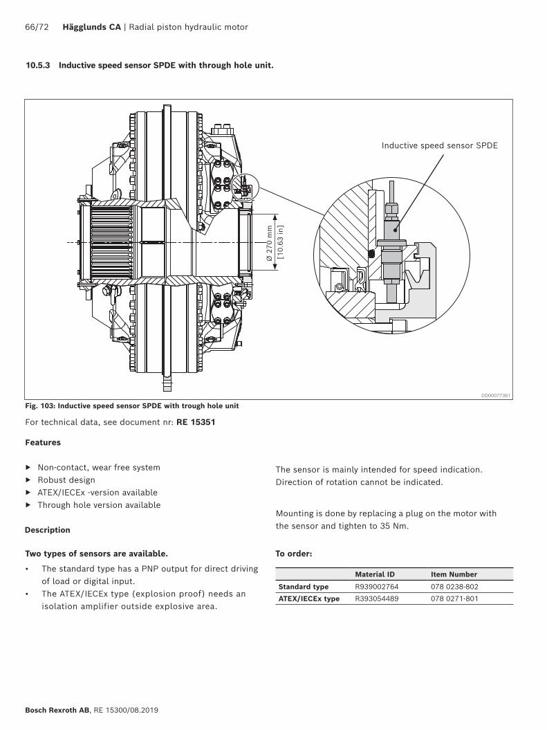
Fig. 103: Inductive speed sensor SPDE with trough hole unit
For technical data, see document nr: RE 15351
10.5.3 Inductive speed sensor SPDE with through hole unit.
Material ID Item Number
Standard type R939002764 078 0238-802
ATEX/IECEx type R393054489 078 0271-801
Inductive speed sensor SPDE
The sensor is mainly intended for speed indication. Direction of rotation cannot be indicated.
Features
▶ Non-contact, wear free system ▶ Robust design ▶ ATEX/IECEx -version available ▶ Through hole version available
Two types of sensors are available.
• The standard type has a PNP output for direct driving of load or digital input.
• The ATEX/IECEx type (explosion proof) needs an isolation amplifier outside explosive area.
Mounting is done by replacing a plug on the motor with the sensor and tighten to 35 Nm.
To order:
Ø 2
70 m
m
Description
DD00077361
[10.
63 in
]
Radial piston hydraulic motor | Hägglunds CA 67/72
RE 15300/08.2019, Bosch Rexroth AB
Am-Cm
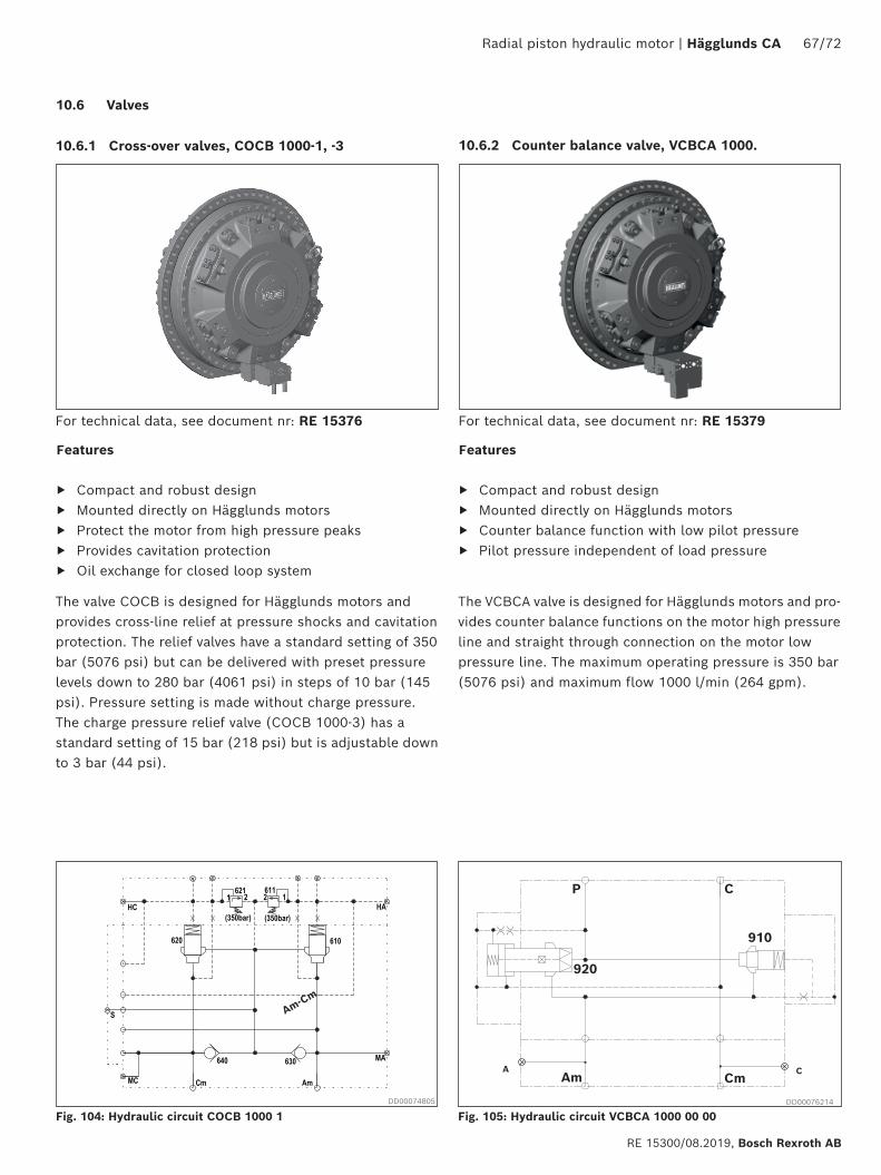
Fig. 104: Hydraulic circuit COCB 1000 1
10.6 Valves
10.6.1 Cross-over valves, COCB 1000-1, -3
The valve COCB is designed for Hägglunds motors and provides cross-line relief at pressure shocks and cavitation protection. The relief valves have a standard setting of 350 bar (5076 psi) but can be delivered with preset pressure levels down to 280 bar (4061 psi) in steps of 10 bar (145 psi). Pressure setting is made without charge pressure.The charge pressure relief valve (COCB 1000-3) has a standard setting of 15 bar (218 psi) but is adjustable down to 3 bar (44 psi).
Features
▶ Compact and robust design ▶ Mounted directly on Hägglunds motors ▶ Protect the motor from high pressure peaks ▶ Provides cavitation protection ▶ Oil exchange for closed loop system
For technical data, see document nr: RE 15376
10.6.2 Counter balance valve, VCBCA 1000.
The VCBCA valve is designed for Hägglunds motors and pro-vides counter balance functions on the motor high pressure line and straight through connection on the motor low pressure line. The maximum operating pressure is 350 bar (5076 psi) and maximum flow 1000 l/min (264 gpm).
Fig. 105: Hydraulic circuit VCBCA 1000 00 00
P C
910
920
Am CmA C
Features
▶ Compact and robust design ▶ Mounted directly on Hägglunds motors ▶ Counter balance function with low pilot pressure ▶ Pilot pressure independent of load pressure
For technical data, see document nr: RE 15379
DD00074805 DD00076214
68/72 Hägglunds CA | Radial piston hydraulic motor
Bosch Rexroth AB, RE 15300/08.2019
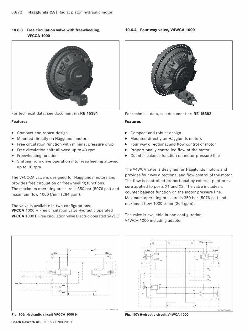
The VFCCCA valve is designed for Hägglunds motors and provides free circulation or freewheeling functions.The maximum operating pressure is 350 bar (5076 psi) and maximum flow 1000 l/min (264 gpm).
The valve is available in two configurations:VFCCA 1000 H Free circulation valve Hydraulic operatedVFCCA 1000 E Free circulation valve Electric operated 24VDC
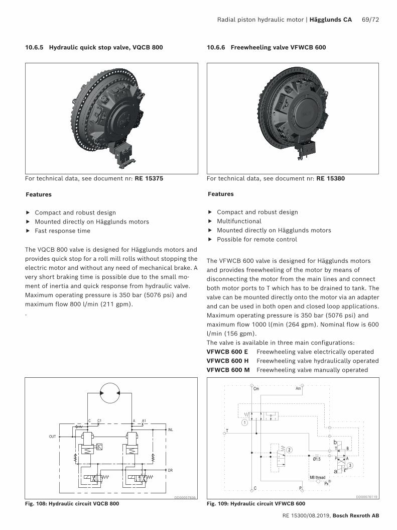
Fig. 107: Hydraulic circuit V4WCA 1000
Features
▶ Compact and robust design ▶ Mounted directly on Hägglunds motors ▶ Free circulation function with minimal pressure drop ▶ Free circulation shift allowed up to 40 rpm ▶ Freewheeling function ▶ Shifting from drive operation into freewheeling allowed
up to 10 rpm
For technical data, see document nr: RE 15381
10.6.3 Free circulation valve with freewheeling, VFCCA 1000
Fig. 106: Hydraulic circuit VFCCA 1000 H
10.6.4 Four-way valve, V4WCA 1000
Features
▶ Compact and robust design ▶ Mounted directly on Hägglunds motors ▶ Four way directional and flow control of motor ▶ Proportionally controlled flow of the motor ▶ Counter balance function on motor pressure line
For technical data, see document nr: RE 15382
The V4WCA valve is designed for Hägglunds motors and provides four way directional and flow control of the motor. The flow is controlled proportional by external pilot pres-sure applied to ports X1 and X2. The valve includes a counter balance function on the motor pressure line. Maximum operating pressure is 350 bar (5076 psi) and maximum flow 1000 l/min (264 gpm).
The valve is available in one configuration:V4WCA-1000 including adapter
DD00076443 DD00076474
Radial piston hydraulic motor | Hägglunds CA 69/72
RE 15300/08.2019, Bosch Rexroth AB
Fig. 108: Hydraulic circuit VQCB 800
10.6.5 Hydraulic quick stop valve, VQCB 800
Features
▶ Compact and robust design ▶ Mounted directly on Hägglunds motors ▶ Fast response time
For technical data, see document nr: RE 15375
The VQCB 800 valve is designed for Hägglunds motors and provides quick stop for a roll mill rolls without stopping the electric motor and without any need of mechanical brake. A very short braking time is possible due to the small mo-ment of inertia and quick response from hydraulic valve.Maximum operating pressure is 350 bar (5076 psi) and maximum flow 800 l/min (211 gpm). .
Fig. 109: Hydraulic circuit VFWCB 600
10.6.6 Freewheeling valve VFWCB 600
Features
▶ Compact and robust design ▶ Multifunctional ▶ Mounted directly on Hägglunds motors ▶ Possible for remote control
For technical data, see document nr: RE 15380
The VFWCB 600 valve is designed for Hägglunds motors and provides freewheeling of the motor by means of disconnecting the motor from the main lines and connect both motor ports to T which has to be drained to tank. The valve can be mounted directly onto the motor via an adapter and can be used in both open and closed loop applications.Maximum operating pressure is 350 bar (5076 psi) and maximum flow 1000 l(min (264 gpm). Nominal flow is 600 l/min (156 gpm).The valve is available in three main configurations:VFWCB 600 E Freewheeling valve electrically operatedVFWCB 600 H Freewheeling valve hydraulically operatedVFWCB 600 M Freewheeling valve manually operated
DD00057836 DD00076119
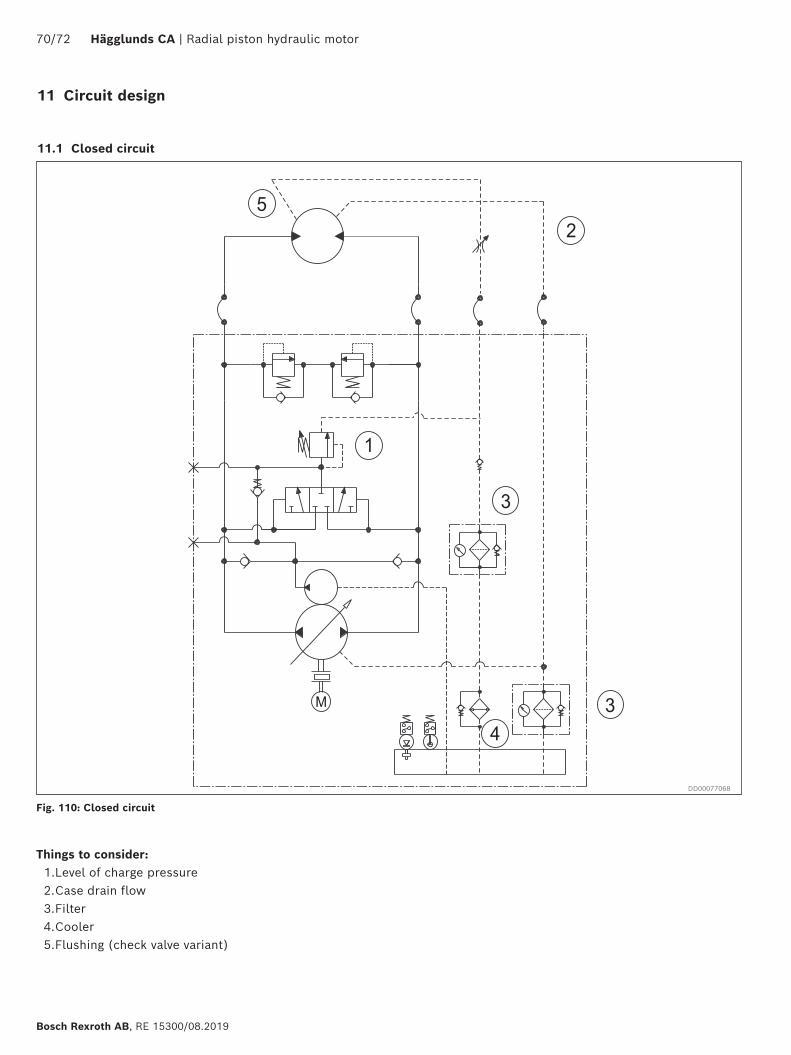
70/72 Hägglunds CA | Radial piston hydraulic motor
Bosch Rexroth AB, RE 15300/08.2019
11 Circuit design
11.1 Closed circuit
Things to consider:1. Level of charge pressure2. Case drain flow3. Filter4. Cooler5. Flushing (check valve variant)
Fig. 110: Closed circuit
DD00077068
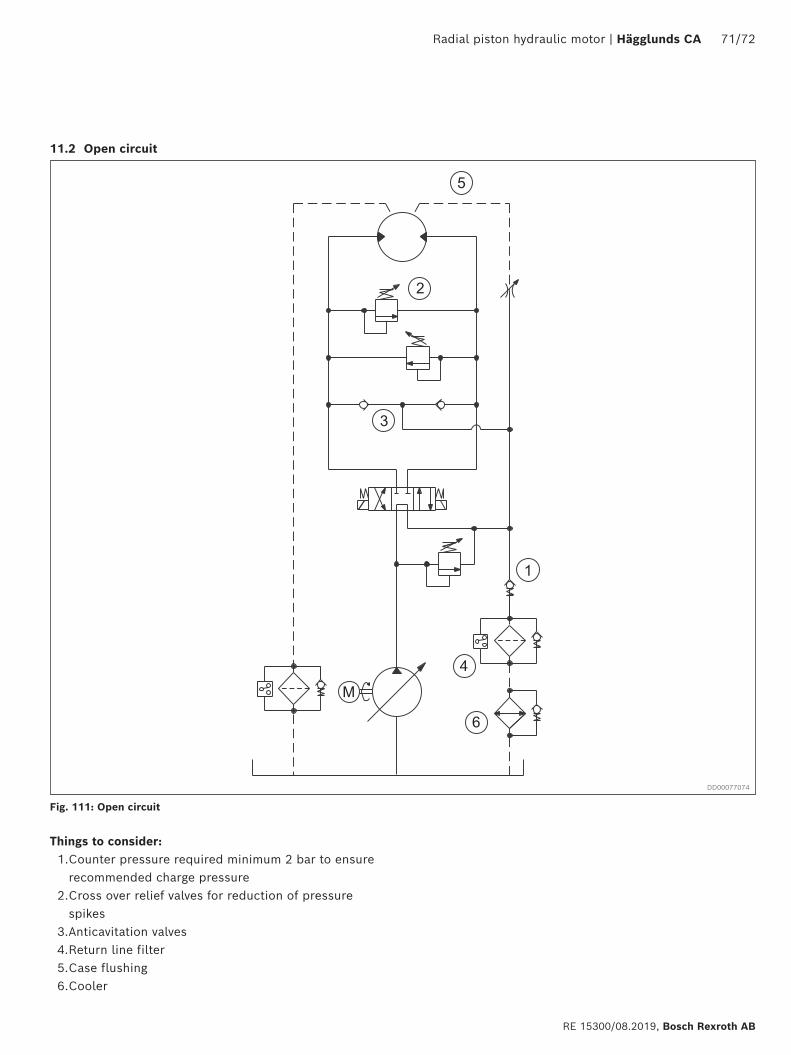
Radial piston hydraulic motor | Hägglunds CA 71/72
RE 15300/08.2019, Bosch Rexroth AB
Things to consider:1. Counter pressure required minimum 2 bar to ensure
recommended charge pressure 2. Cross over relief valves for reduction of pressure
spikes3. Anticavitation valves4. Return line filter5. Case flushing6. Cooler
11.2 Open circuit
Fig. 111: Open circuit
DD00077074
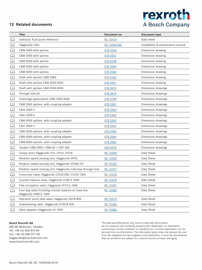
Bosch Rexroth AB895 80 Mellansel, SwedenTel: +46 (0) 660 870 00Fax: +46 (0) 660 871 [email protected]
The data specified above only serve to describe the product. As our products are constantly being further developed, no statements concerning a certain condition or suitability for a certain application can be derived from ourinformation. The information given does not release the user from the obligation of own judgment and verification. It must be remembered that our products are subject to a natural process of wear and aging
Bosch Rexroth AB, RE 15300/08.2019
Title Document no Document type
Hydraulic fluid quick reference RE 15414 Data sheet
Hägglunds CBm RE 15300-WA Installation & maintenance manual
CBM 2000 with splines 078 2556 Dimension drawing
CBM 3000 with splines 078 2557 Dimension drawing
CBM 4000 with splines 078 2558 Dimension drawing
CBM 5000 with splines 078 2559 Dimension drawing
CBM 6000 with splines 078 2560 Dimension drawing
Shaft with splines CBM 2000 078 2432 Dimension drawing
Shaft with splines CBM 3000-4000 078 2451 Dimension drawing
Shaft with splines CBM 5000-6000 078 2673 Dimension drawings
Through hole kit 078 2674 Dimension drawings
Submerge applications CBM 2000-4000 078 2758 Dimension drawings
CBM 2000 splines, with coupling adapter 078 2561 Dimension drawings
CBm 2000 C 078 5304 Dimension drawings
CBm 2000 E 078 5342 Dimension drawings
CBM 3000 splines, with coupling adapter 078 2562 Dimension drawings
CBm 3000 C 078 5343 Dimension drawings
CBM 4000 splines, with coupling adapter 078 2563 Dimension drawings
CBM 5000 splines, with coupling adapter 078 2564 Dimension drawings
CBM 6000 splines, with coupling adapter 078 2565 Dimension drawings
Tandem CBM 2000 +TBM 40 + CBP 400 078 2676 Dimension drawings
Torque arms Hägglunds TCA, DTCA, DTCB RE 15355 Data Sheet
Rotation speed sensing unit, Hägglunds SPDC RE 15350 Data Sheet
Rotation speed sensing unit, Hägglunds SPDB2 EX RE 15352 Data Sheet
Rotation speed sensing unit, Hägglunds Inductive through hole RE 15351 Data Sheet
Cross-over valve, Hägglunds COCB 500, COCB 1000 RE 15376 Data Sheet
Counter balance valve, Hägglunds VCBCA 1000 RE 15379 Data Sheet
Free circulation valve, Hägglunds VFCCA 1000 RE 15381 Data Sheet
Four-way valve including counter balance on load line,Hägglunds V4WCA 1000
RE 15382 Data Sheet
Hydraulic quick stop valve, Hägglunds VQCB 800 RE 15375 Data Sheet
Freewheeling valve, Hägglunds VFWCB 600 RE 15380 Data Sheet
Valve adapters Hägglunds VA 1000 RE 15383 Data Sheet
12 Related documents
Related Documents