Radar Presentation Restitutor* ROBERT P. MACCHIA, Engineer Research and Development Laboratories, Fort Belvoir, Virginia ABSTRACT: This paper describes the Radar Presentation Restitutor, an instrument designed and developed to correct positions on a 360 degree scan Plan Position Indicator radar scope photograph to their equivalent ground positions. Principles of operation of the instrument are optical- mechanical. The following corrections are performed automatically: 1. Distortion due to slant-range 2. Distortion due to sweep-delay 3. Distortion due to aircraft motion during a single scan. Provision also has been made to introduce correctionsfor distortion due to: 4. Non-uniform motion of the electronic sweep 5. The lens of the recording camera, and 6. Curvature of the cathode ray tube. The above corrections can be performed simultaneously in one operation. The heart of the system is essentially a pair of rotating mirrors having a 90 degrees apex angle. The special properties of the system ar:; discussed and some results using test patterns are shown. T HE Topographic Engineering Depart- ment of the Engineer Research and Development Laboratories was assigned a project several years ago-seven to be ex- act-to investigate the utilization of radar photography for mapping. As is generally known, the all-weather capability of radar is its most inviting factor, and as a result has created many investigations for its ap- plication to mapping and charting. The subject of this paper-the Radar Presentation Restitutor-is an optical- mechanical instrument which corrects for various distortions contained in the radar PPI photograph. Photogrammetrically, this instrument can be considered as paral- leling the rectifier for optical photography. Figure 1 shows a radar PPI presenta- tion. The center of the photograph repre- sents the nadir point on the ground. The radar antenna, in transmitting, illuminates with energy a radial line on the ground, emanating from the nadir point. The an- tenna then receives the energy reflections and rotates through a small increment, continually transmitting and then receiv- ing electromagnetic energy, repeating this until it has rotated through 360 degrees. ROBERT P. MACCHIA The distortions confronting the radar mapper are indicated on Figure 2. * Presented at Society's 23rd Annual Meeting, Hotel Shoreham, Washington, D. C. March 5, 1957. 8£0

Welcome message from author
This document is posted to help you gain knowledge. Please leave a comment to let me know what you think about it! Share it to your friends and learn new things together.
Transcript

Radar Presentation Restitutor*
ROBERT P. MACCHIA,
Engineer Research and Development Laboratories,Fort Belvoir, Virginia
ABSTRACT: This paper describes the Radar Presentation Restitutor, aninstrument designed and developed to correct positions on a 360 degreescan Plan Position Indicator radar scope photograph to their equivalentground positions. Principles of operation of the instrument are opticalmechanical.
The following corrections are performed automatically:1. Distortion due to slant-range2. Distortion due to sweep-delay3. Distortion due to aircraft motion during a single scan.
Provision also has been made to introduce corrections for distortion due to:4. Non-uniform motion of the electronic sweep5. The lens of the recording camera, and6. Curvature of the cathode ray tube.
The above corrections can be performed simultaneously in one operation.The heart of the system is essentially a pair of rotating mirrors
having a 90 degrees apex angle. The special properties of the system ar:;discussed and some results using test patterns are shown.
T HE Topographic Engineering Department of the Engineer Research and
Development Laboratories was assigned aproject several years ago-seven to be exact-to investigate the utilization of radarphotography for mapping. As is generallyknown, the all-weather capability of radaris its most inviting factor, and as a resulthas created many investigations for its application to mapping and charting.
The subject of this paper-the RadarPresentation Restitutor-is an opticalmechanical instrument which corrects forvarious distortions contained in the radarPPI photograph. Photogrammetrically,this instrument can be considered as paralleling the rectifier for optical photography.
Figure 1 shows a radar PPI presentation. The center of the photograph represents the nadir point on the ground. Theradar antenna, in transmitting, illuminateswith energy a radial line on the ground,emanating from the nadir point. The antenna then receives the energy reflectionsand rotates through a small increment,continually transmitting and then receiving electromagnetic energy, repeating thisuntil it has rotated through 360 degrees.
ROBERT P. MACCHIA
The distortions confronting the radarmapper are indicated on Figure 2.
* Presented at Society's 23rd Annual Meeting, Hotel Shoreham, Washington, D. C. March 5,1957.
8£0
RADAR PRESENTATION RESTITUTOR 881
FIG. 1. Radar PPI presentation.
The first three distortions have thegreatest effect on the radar accuracy,whereas the remaining distortions can beconsidered minor in the present state of theart of radar mapping.
The basis for slant-range distortion isevident from Figure 3. The radar measuresthe distance from the antenna to the targetand is recorded as this distance rather thanthe true ground range.
The distortion due to sweep-delay .is actually put into the system out of practicalnecessity. As shown on Figure 4, if the traceon the cathode ray tube is started at thesame instant that the energy is radiatedfrom the antenna, the first return cannotshow until the energy has travelled to theground and returned. A distance to scale,corresponding to the altitude, is thereforewasted on the cathode ray tube. The altitude hole--the area of no return at the PPIcenter-is marked evidence of this effect.For this reason the trace on the CRT is delayed for some interval of time, depending
FIG. 2. DISTORTIONS CORRECTED BY THE
RADAR PRESENTATION RESTITUTOR.
1. Slant-range distortion2. Sweep-delay distortion3. Aircraft motion4. Non-uniformity of the electronic
sweep5. Lens-distortion from the recording
camera6. Curvature of the cathode ray tu be.
ANTENNA ___
ALTITUDE H
tL__=::::;:--;;:::;:-;-------~T...RGETGROUND R"'NG~ ...
FIG. 3. The basis for slant range distorticn.
on the altitude, in order to start the returns closer to the center of the CRT. Thus,for any given range set into the radar, amaximum area of the CRT face is availablefor the display and consequently the scaleof the display is maximized.
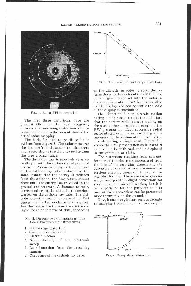
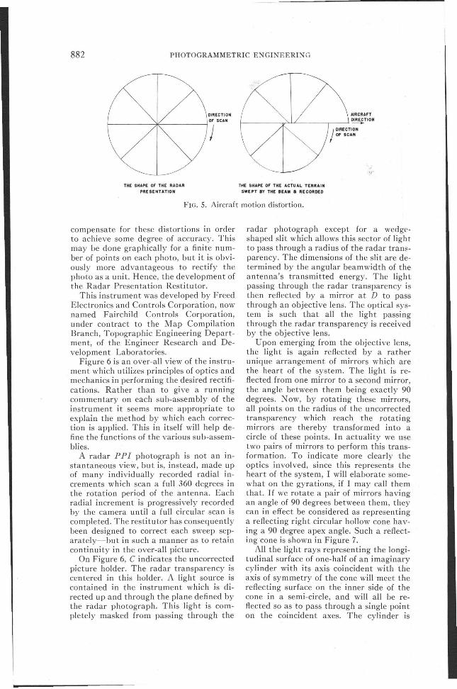
The distortion due to aircraft motionduring a single scan results from the factthat the narrow radial sweeps making upthe scan all have a common origin on thePP I presentation. Each successive radialsector should emanate instead along a linerepresenting the motion of the nadir of theaircraft during a single scan. Figure SA,shows the PPI presentation as it is and Bas it should be wi th each radius displacedin the direction of flight.
The distortions resulting from non-uniformity of the electronic sweep, and fromthe lens of the recording camera and thecurvature of the scope face, are minor distortions affecting range which may be disregarded for now. There are radar systemswhich incorporate in-flight corrections forslant range and aircraft motion, but it isour experience (or our purposes that atpresent these corrections can be performedmore accurately on the ground.
N ow, if one is to give any serious thoughtto mapping from radar, it is necessary to
GROUND
FIG. 4. Sweep delay distortion.
882 PHOTOGRAMMETRIC E~GINEERI:-<G
jOIRECTlONOF SCAN
e-----*----~
THE SHAPE OF THE RADAR
PRESENTATION
AIRCRAFT
f----~"'-'-/----r----< ~TION
THE SHAPE OF THE ACTUAL TERRAIN
SWEPT IY THE 8EAM • RECORDED
FIG. 5. Aircraft motion distortion.
compensate for these distortions in orderto achieve some degree of accuracy. Thismay be done graphically for a finite number of points on each photo, but it is obviously more advantageous to rectify thephoto as a unit. Hence, the development ofthe Radar Presentation Restitutor.
This instrument was developed by FreedElectronics and Controls Corporation, nownamed Fairchild Controls Corporation,under contract to the Map CompilationBranch, Topographic Engineering Department, of the Engineer Research and Development Laboratories.
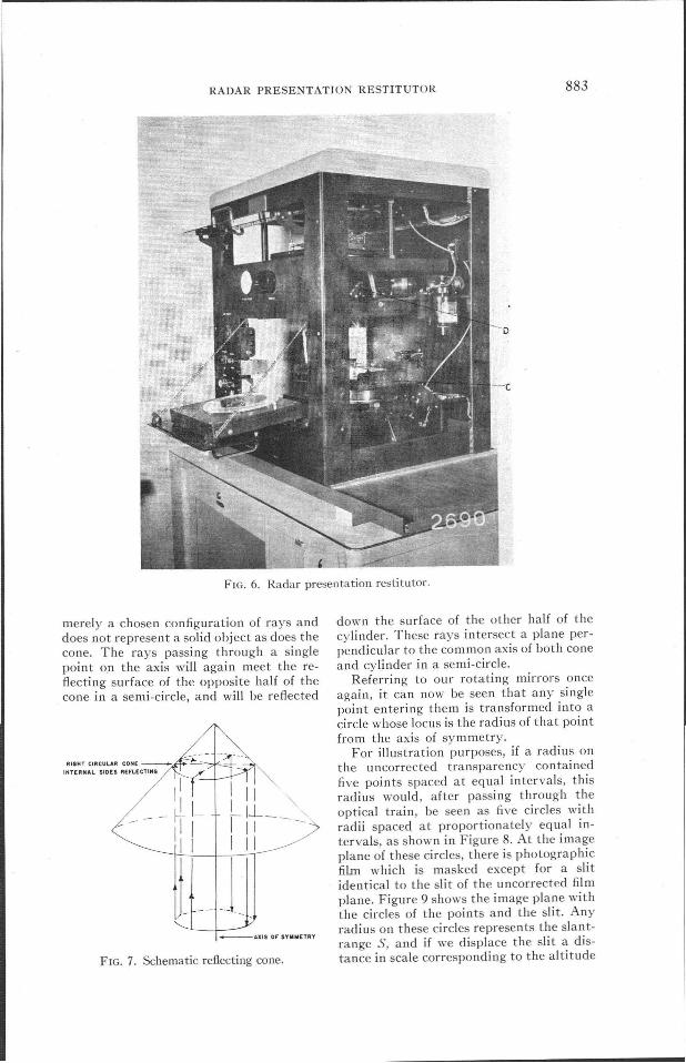
Figure 6 is an over-all view of the instrument which utilizes principles of optics andmechanics in performing the desired rectifications. Rather than to give a runningcommentary on each sub-assembly of theinstrument it seems more appropriate toexplain the method by which each correction is applied. This in itself will help define the functions of the various sub-assemblies.
A radar PP I photograph is not an instantaneous view, but is, instead, made upof many individually recorded radial increments which scan a full 360 degrees inthe rotation period of the antenna. Eachradial increment is progressively recordedby the camera until a full circular scan iscompleted. The restitutor has consequentlybeen designed to correct each sweep separately-but in such a manner as to retaincontinuity in the over-all picture.
On Figure 6, C indicates the uncorrectedpicture holder. The radar transparency iscentered in this holder. A light source iscontained in the instrument which is directed up and through the plane defined bythe radar photograph. This light is completely masked from passing through the
radar photograph except for a wedgeshaped slit which allows this sector of lightto pass through a radius of the radar transparency. The dimensions of the slit are determined by the angular beamwidth of theantenna's transmitted energy. The lightpassing through the radar transparency isthen reflected by a mirror at D to passthrough an objective lens. The optical system is such that all the light passingthrough the radar transparency is receivedby the objective lens.
Upon emerging from the objective lens,the light is again reflected by a ratherunique arrangement of mirrors which arethe heart of the system. The light is reflected from one mirror to a second mirror,the angle between them being exa~tly 90degrees. Now, by rotating these mirrors,all points on the radius of the uncorrectedtransparency which reach the rotatingmirrors are thereby transformed into acircle of these points. In actuality we usetwo pairs of mirrors to perform this transformation. To indicate more clearly theoptics involved, since this represents theheart of the system, I will elaborate somewhat on the gyrations, if I may call themthat. If we rotate a pair of mirrors havingan angle of 90 degrees between them, theycan in effect be considered as representinga reflecting right circular hollow cone having a 90 degree apex angle. Such a reflecting cone is shown in Figure 7.
All the light rays representing the longitudinal surface of one-half of an imaginarycylinder with its axis coincident with theaxis of symmetry of the cone will meet thereflecting surface on the inner side of thecone in a semi-circle, and will all be reflected so as to pass through a single pointon the coincident axes. The cylinder is
RADAR PRESENTATION RESTITUTOR
FIG. 6. Radar presentation restitutor.
883
merely a chosen configuration of rays anddoes not represent a solid object as does thecone. The rays passing through a singlepoint o.n the axis will again meet the reflecting surface of the opposite half of thecone in a semi-circle, and will be reflected
RIGHT CIRCULAR CONE_
IrrtTERHAt. SIDES REFLECTING
_AXIS OF SYWMETRY
FIG. 7. Schematic reflecting cone.
down the surface of the other half of thecylinder. These rays intersect a plane perpendicular to the common axis of both coneand cylinder in a semi-circle.
Referring to our rotating mirrors onceagain, it can now be seen that any singlepoint entering them is transformed into acircle whose locus is the radius of that pointfrom the axis of symmetry.
For illustration purposes, if a radius onthe uncorrected transparency containedfive points spaced at equal intervals, thisradius would, after passing through theoptical train, be seen as five circles withradii spaced at proportionately equal intervals, as shown in Figure 8. At the imageplane of these circles, there is photographicfilm which is masked except for a slitidentical to the slit of the uncorrected filmplane. Figure 9 shows the image plane withthe circles of the points and the slit. Anyradius on these circles represents the slantrange S, and if we displace the slit a distance in scale corresponding to the altitude

884 PHOTOGRAMMETRIC ENGINEERING
SLIT
SLANT RANGE·5
'4
'3
'2
'1
'ORIGIN
FIG. 8. Transformation of equally spacedpoints into equally spaced circles.
H, the image produced on the film will represent the ground range G. This is simplythe pythagorean theorem. To correct theentire radar presentation for slant-rangemerely requires that we rotate the uncorrected and corrected film planes simultaneously, through 360 degrees.
The correction for sweep-delay is appliedsimply by shifting the uncorrected radartransparency so that the uncorrectedradius is increased in length in the imageplane to present the true slant-range. Theaircraft motion correction is performed atthe same time by translating the photographic film in the direction of flight whileit is rotating, so that each sweep-radius isdisplaced its proper distance from the origin of the start of the scan. This translationis performed by using a rack, a pinion anda cam which engages the corrected film
FIG. 9. Slant range correction at image plane.
holder. By adjusting the angle between thecam and the rack, and rotating the pinionwhich is controlled by rotation of the twofilm planes, the photographic film can betranslated the proper distance corresponding to the aircraft displacement for eachsuccessive sweep. This translation is a uniform motion since we assume a constantspeed for the aircraft in the scan period.
An example of each correction can beseen in illustrations 10 to 13. The photo onthe left is the test pattern or the uncorrected transparency and the one on theright is corrected.
Figure 10 shows the original and the final
FIG. 10. Slant range correction, altitude/range ratio of .4. At left-Test pattern,At right-Corrected test pattern.

RADAR PRESENTATION RESTITUTOR
FIG. 11. Sweep-delay correction, sweep delay .08 of range. At left-Test pattern.At right-Corrected test pattern.
885
product after correction for slant-rangeusing an altitude/range ratio of .4. It willbe noticed that the image has been compressed and that the four innermost circleson the original are no longer present.
Figure 11 represents the correction forsweep-delay and is shown as a linear expansion. Notice that the center circle is enlarged.
Figure 12 is an example of the aircraftmotion correction. It was assumed that themotion equaled the distance between thesuccessive radii and the result is a continuous spiral.
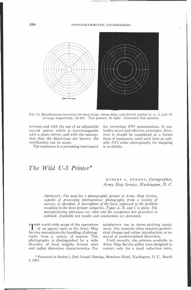
Figure 13 represents the simultaneous
correction for altitude, sweep-delay andaircraft-motion.
The above corrections are set into theinstrument simply by turning two dialsand one micrometer screw. The instrumentis set into operation by pressing a starterbutton, and three minutes later the corrected film is ready for development.
By empirical means the instrument canbe made to compensate for nonuniformityof the electronic sweep, lens-distortionfrom the recording camera and curvatureof the CRT face. These corrections are notautomatic though they are simultaneouslyexecuted. Fortunately these are radial dis-
FIG. 12. Aircraft motion correction, .1 of range. At left-Test pattern.At right-Corrected test pattern.
886 PHOTOGRAMMETRIC ENGINEERING
FIG. 13. Simultaneous correction for slant range, sweep delay and aircraft motion at .4, .2, and .OJcf range respectively. At left-Test pattern. At right-Corrected Test pattern.
tortions and with the use of an adjustablecurved mirror which is in terchangeablewith a plane mirror, and with the assumption that the distortions are known, therectification can be made.
The restitutor is a promising instrument
The Wild U-3 Printer*
for correcting PPI presentations. It embodies novel and effective principles. However it should be considered as a futureitem of equipment until such time as suitable P P I radar photography for mappingis available.
ROBERT A. PENNEY, Cartographer,Army Map Service, Washington, D. C.
ABSTRACT: The need for a photographic printer at Army Map Service,capable of processing heterogeneous photography from a variety ofsources, is specified. A description of the basic approach to the problemresulting in the three printer categories, Types A, B, and C is given. Themanufacturing tolerances are cited and the acceptance test procedure isoutlined. Available test results and conclusions are presented.
T HE world-wide scope of the operationsof an agency such as the Army Map
Service necessitates the handling of photography from a variety of sources. Thisphotography is distinguished by a widediversity of focal lengths, format sizesand radial distortion characteristics. For
satisfactory use in stereo-plotting equipmen t, this material often requires geometrical change and either introduction or removal of predetermined distortion.
Until recently, the printers available toArmy Map Service either were designed tocorrect only for a fixed reduction ratio,
* Presented at Society's 23rd Annual Meeting, Shoreham Hotel, Washington, D. c., March5, 1957.
Related Documents