OPERATION AND MAINTENANCE MANUAL C.C.N. : 80445802 DATE : FEBRUARY 2010 REV. : B R90 - 110N R90 - 110I Ensure that the operator reads and understands the decals and consults the manuals before maintenance or operation. Ensure that the Operation and Maintenance manual is not removed permanently from the machine. Ensure that maintenance personnel are adequately trained, competent and have read the Maintenance Manuals.

Welcome message from author
This document is posted to help you gain knowledge. Please leave a comment to let me know what you think about it! Share it to your friends and learn new things together.
Transcript
OPERATION AND MAINTENANCE MANUAL
C.C.N. : 80445802DATE : FEBRUARY 2010REV. : B
R90 - 110NR90 - 110I
Ensure that the operator reads and understands the decals and consults the manuals before maintenance or operation.Ensure that the Operation and Maintenance manual is not removed permanently from the machine.Ensure that maintenance personnel are adequately trained, competent and have read the Maintenance Manuals.

AIR COMPRESSOR GROUP BONDED WARRANTY & REGISTERED START UP
WARRANTYThe Company warrants that the equipment manufactured by it and delivered hereunder will be free of defects in material and workmanship for a period of twelve months from the date of placing the Equipment in operation or eighteen months from the date of shipment from the factory, whichever shall first occur. The Purchaser shall be obligated to promptly report any failure to conform to this warranty, in writing to the Company in said period, whereupon the Company shall, at its option, correct such nonconformity, by suitable repair to such equipment or, furnish a replacement part F.O.B. point of shipment, provided the Purchaser has stored, installed, maintained and operated such Equipment in accordance with good industry practices and has complied with specific recommendations of the Company. Accessories or equipment furnished by the Company, but manufactured by others, shall carry whatever warranty the manufacturers have conveyed to the Company and which can be passed on to the Purchaser. The Company shall not be liable for any repairs, replacements, or adjustments to the Equipment or any costs of labor performed by the Purchaser or others without Company‘s prior written approval.
The effects of corrosion, erosion and normal wear and tear are specifically excluded. Performance warranties are limited to those specifically stated within the Company‘s proposal. Unless responsibility for meeting such performance warranties are limited to specified tests, the Company‘s obligation shall be to correct in the manner and for the period of time provided above.
THE COMPANY MAKES NO OTHER WARRANTY OR REPRESENTATION OF ANY KIND WHATSOEVER, EXPRESSED OR IMPLIED, EXCEPT THAT OF TITLE, AND ALL IMPLIED WARRANTIES OF MERCHANTABILITY AND FITNESS FOR A PARTICULAR PURPOSE, ARE HEREBY DISCLAIMED.
Correction by the Company of nonconformities whether patent or latent, in the manner and for the period of time provided above, shall constitute fulfillment of all liabilities of the Company for such non conformities whether based on contract, warranty negligence, indemnity, strict liability or otherwise with respect to or arising out of such Equipment.
The purchaser shall not operate Equipment which is considered to be defective, without first notifying the Company in writing of its intention to do so. Any such use of Equipment will be at Purchaser‘s sole risk and liability.
Note that this is Ingersoll Rand standard warranty. Any warranty in force at the time of purchase of the compressor or negotiated as part of the purchase order may take precedence over this warranty.

R90 - 110N & R90 - 110Ihttp://www.ingersollrandproducts.com
1
1.0 CONTENTS CONTENTS PAGE CONTENTS PAGE
1.0 CONTENTS 1
2.0 FOREWORD 2
3.0 ABBREVIATIONS & SYMBOLS 4
4.0 PURCHASE ORDER DETAILS 5
5.0 SAFETY 6
5.1 SAFETY INSTRUCTIONS 6
5.2 SAFETY PRECAUTIONS 6
5.3 TEXT DECALS 9
5.4 GRAPHIC FORM AND MEANING OF ISO SYMBOLS 12
6.0 RECEIPT / HANDLING 14
6.1 RECEIPT 14
6.2 UNPACKING AND HANDLING 14
6.3 LONG TERM STORAGE 14
7.0 INSTALLATION 15
7.1 LOCATION IN PLANT 15
7.2 DISCHARGE AND CONDENSATE PIPING 16
7.3 ELECTRICAL 17
7.4 WATERCOOLED UNITS 19
7.5 ENVIRONMENTAL LIMITS 21
8.0 GENERAL INFORMATION 22
8.1 GENERAL ARRANGEMENT, AIR COOLED (R90-110) 22
8.1 GENERAL ARRANGEMENT, WATER COOLED (R90-110) 28
8.2 PROCESS AND INSTRUMENTATION DIAGRAM (AC/WC) 90-160 KW (VSD) 33
8.2 PROCESS AND INSTRUMENTATION DIAGRAM (A.C/W.C) 90-160 KW (FS) 35
8.2 PROCESS AND INSTRUMENTATION DIAGRAM ENERGY RECOVERY SYSTEM 38
8.3 SCHEMATIC, ELECTRICAL WIRING (VSD) 40
8.3 SCHEMATIC, ELECTRICAL WIRING (FIXED SPEED - Y/D) (STANDARD) 42
8.3 SCHEMATIC, ELECTRICAL WIRING (FIXED SPEED - SOFT STARTER) (OPTION) 44
8.4 GENERAL DESCRIPTION 46
9.0 OPERATING INSTRUCTIONS 47
9.1 OPERATING INSTRUCTIONS FOR VSD 47
9.1.1 BASIC OPERATION 47
9.1.2 INTELLISYS CONTROLS (VSD) 49
9.1.3 DISPLAY SCREEN 50
9.1.4 CURRENT STATUS SCREEN 51
9.1.5 MAIN MENU 52
9.1.6 OPERATOR SETPOINTS 53
9.1.7 OPTIONS 55
9.1.8 SENSOR CALIBRATION 56
9.1.9 TRIP HISTORY 57
9.1.10 CLOCK FUNCTIONS 57
9.1.11 ENERGY STATUS MESSAGES 58
9.1.12 WARNINGS 59
9.1.13 SERVICE WARNINGS 59
9.1.14 INITIAL CHECK TRIPS: 59
9.1.15 TRIPS 60
9.2 OPERATING INSTRUCTIONS FOR FS 61
10.0 MAINTENANCE 71
10.1 MAINTENANCE PROMPTS 71
10.2 MAINTENANCE CHART 72
10.3 MAINTENANCE PROCEDURES 73
10.4 ROUTINE MAINTENANCE 75
10.5 STARTER BOX PANEL FILTER (VSD ONLY) 81
11.0 FAULT FINDING (VSD) 82
11.1 GENERAL FAULTS 82
11.2 INTELLISYS FAULTS (INDICATED ON THE INTELLISYS CONTROLLER) 85
11.3 DRIVE FAULTS (INDICATED ON THE INTELLISYS CONTROLLER) 87
R90 - 110N & R90 - 110Ihttp://www.ingersollrandproducts.com�
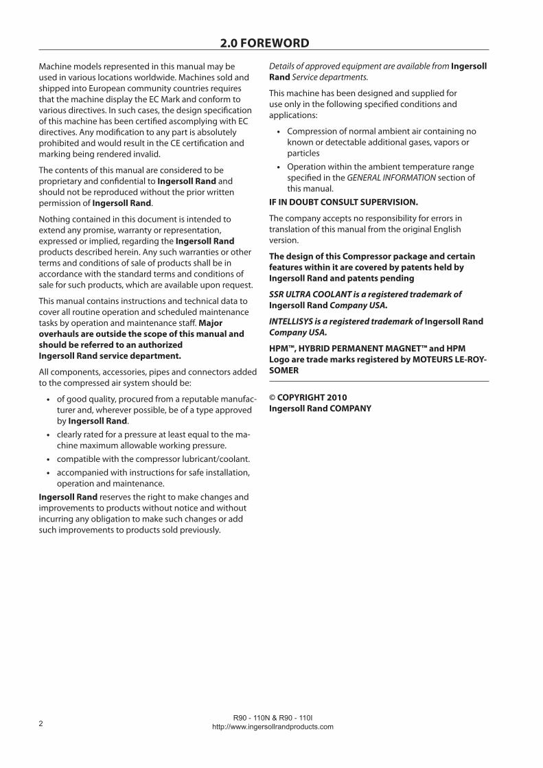
2.0 FOREWORD
Machine models represented in this manual may be used in various locations worldwide. Machines sold and shipped into European community countries requires that the machine display the EC Mark and conform to various directives. In such cases, the design specification of this machine has been certified ascomplying with EC directives. Any modification to any part is absolutely prohibited and would result in the CE certification and marking being rendered invalid.
The contents of this manual are considered to be proprietary and confidential to Ingersoll Rand and should not be reproduced without the prior written permission of Ingersoll Rand.
Nothing contained in this document is intended to extend any promise, warranty or representation, expressed or implied, regarding the Ingersoll Rand products described herein. Any such warranties or other terms and conditions of sale of products shall be in accordance with the standard terms and conditions of sale for such products, which are available upon request.
This manual contains instructions and technical data to cover all routine operation and scheduled maintenance tasks by operation and maintenance staff. Major overhauls are outside the scope of this manual and should be referred to an authorized Ingersoll Rand service department.
All components, accessories, pipes and connectors added to the compressed air system should be:
of good quality, procured from a reputable manufac-turer and, wherever possible, be of a type approved by Ingersoll Rand.clearly rated for a pressure at least equal to the ma-chine maximum allowable working pressure.compatible with the compressor lubricant/coolant.accompanied with instructions for safe installation, operation and maintenance.
Ingersoll Rand reserves the right to make changes and improvements to products without notice and without incurring any obligation to make such changes or add such improvements to products sold previously.
•
•
••
Details of approved equipment are available from Ingersoll Rand Service departments.
This machine has been designed and supplied for use only in the following specified conditions and applications:
Compression of normal ambient air containing no known or detectable additional gases, vapors or particlesOperation within the ambient temperature range specified in the GENERAL INFORMATION section of this manual.
IF IN DOUBT CONSULT SUPERVISION.
The company accepts no responsibility for errors in translation of this manual from the original English version.
The design of this Compressor package and certain features within it are covered by patents held by Ingersoll Rand and patents pending
SSR ULTRA COOLANT is a registered trademark of Ingersoll Rand Company USA.
INTELLISYS is a registered trademark of Ingersoll Rand Company USA.
HPM™, HYBRID PERMANENT MAGNET™ and HPM Logo are trade marks registered by MOTEURS LE-ROY-SOMER
© COPYRIGHT 2010 Ingersoll Rand COMPANY
•
•
R90 - 110N & R90 - 110Ihttp://www.ingersollrandproducts.com �
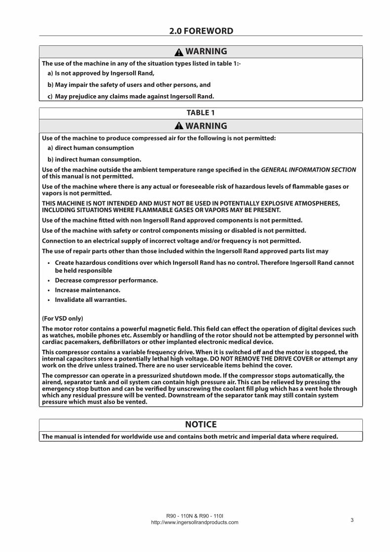
WARNINGThe use of the machine in any of the situation types listed in table 1:-
Is not approved by Ingersoll Rand,
May impair the safety of users and other persons, and
May prejudice any claims made against Ingersoll Rand.
a)
b)
c)
TABLE 1
WARNINGUse of the machine to produce compressed air for the following is not permitted:
direct human consumption
indirect human consumption.
Use of the machine outside the ambient temperature range specified in the GENERAL INFORMATION SECTION of this manual is not permitted.
Use of the machine where there is any actual or foreseeable risk of hazardous levels of flammable gases or vapors is not permitted.
THIS MACHINE IS NOT INTENDED AND MUST NOT BE USED IN POTENTIALLY EXPLOSIVE ATMOSPHERES, INCLUDING SITUATIONS WHERE FLAMMABLE GASES OR VAPORS MAY BE PRESENT.
Use of the machine fitted with non Ingersoll Rand approved components is not permitted.
Use of the machine with safety or control components missing or disabled is not permitted.
Connection to an electrical supply of incorrect voltage and/or frequency is not permitted.
The use of repair parts other than those included within the Ingersoll Rand approved parts list may
Create hazardous conditions over which Ingersoll Rand has no control. Therefore Ingersoll Rand cannot be held responsibleDecrease compressor performance.Increase maintenance.Invalidate all warranties.
(For VSD only)
The motor rotor contains a powerful magnetic field. This field can effect the operation of digital devices such as watches, mobile phones etc. Assembly or handling of the rotor should not be attempted by personnel with cardiac pacemakers, defibrillators or other implanted electronic medical device.
This compressor contains a variable frequency drive. When it is switched off and the motor is stopped, the internal capacitors store a potentially lethal high voltage. DO NOT REMOVE THE DRIVE COVER or attempt any work on the drive unless trained. There are no user serviceable items behind the cover.
The compressor can operate in a pressurized shutdown mode. If the compressor stops automatically, the airend, separator tank and oil system can contain high pressure air. This can be relieved by pressing the emergency stop button and can be verified by unscrewing the coolant fill plug which has a vent hole through which any residual pressure will be vented. Downstream of the separator tank may still contain system pressure which must also be vented.
a)
b)
•
•••
NOTICEThe manual is intended for worldwide use and contains both metric and imperial data where required.
2.0 FOREWORD

R90 - 110N & R90 - 110Ihttp://www.ingersollrandproducts.com�
3.0 ABBREVIATIONS & SYMBOLS#### Contact Ingersoll Rand for serial number
->#### Up to Serial No.
####-> From Serial No.
* Not illustrated
† Option
NR Not required
AR As required
SM Sitemaster/Sitepack
VSD Variable Speed Drive
FS Fixed Speed
PDM Power Drive Module (Starter Box for VSD Units)
HA High ambient machine
WC Watercooled machine
AC Aircooled machine
ERS Energy recovery system
T.E.F.C. Totally enclosed fan cooled motor (IP54)
O.D.P. Open drip proof (motor)
ppm parts per million
bg Bulgarian
cs Czech
da Danish
de German
el Greek
en English
es Spanish
et Estonian
fi Finnish
fr French
hu Hungarian
it Italian
lt Lithuanian
lv Latvian, Lettish
mt Maltese
nl Dutch
no Norwegian
pl Polish
pt Portuguese
ro Romanian
ru Russian
sk Slovak
sl Slovenian
sv Swedish
zh Chinese

R90 - 110N & R90 - 110Ihttp://www.ingersollrandproducts.com �
4.0 PURCHASE ORDER DETAILS
ROTARY SCREW AIR COMPRESSOR
This unit was purchased from
_____________________________________________________________
_____________________________________________________________
_____________________________________________________________
Ingersoll Rand Company reserves the right to make changes or add improvements without notice and without incurring any obligation to make such changes or add such improvements to products sold previously.
No. of units on order: ___________________________________________
Customer Order No: ____________________________________________
Ingersoll Rand Co. Order No _____________________________________
For ready reference:
Record the serial number and model number of your unit here.
Serial Number: ________________________________________________
Model Number: _______________________________________________
R90 - 110N & R90 - 110Ihttp://www.ingersollrandproducts.com
�
5.0 SAFETY
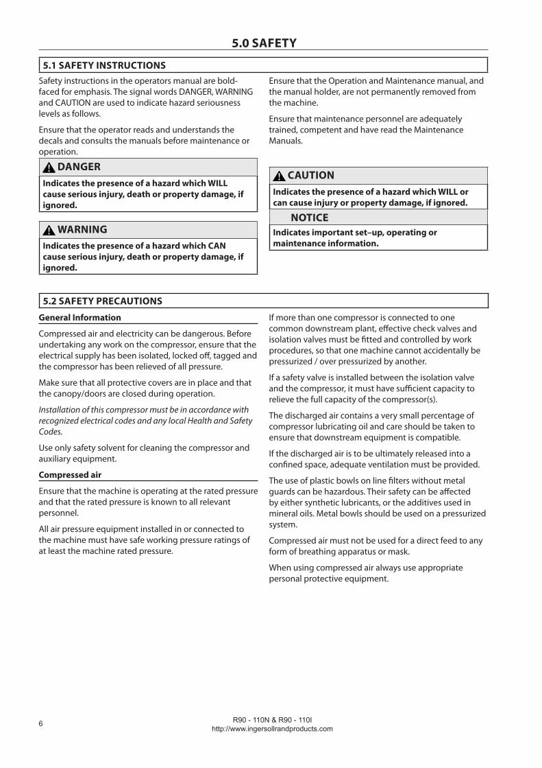
5.1 SAFETY INSTRUCTIONSSafety instructions in the operators manual are bold-faced for emphasis. The signal words DANGER, WARNING and CAUTION are used to indicate hazard seriousness levels as follows.
Ensure that the operator reads and understands the decals and consults the manuals before maintenance or operation.
DANGERIndicates the presence of a hazard which WILL cause serious injury, death or property damage, if ignored.
WARNINGIndicates the presence of a hazard which CAN cause serious injury, death or property damage, if ignored.
Ensure that the Operation and Maintenance manual, and the manual holder, are not permanently removed from the machine.
Ensure that maintenance personnel are adequately trained, competent and have read the Maintenance Manuals.
CAUTIONIndicates the presence of a hazard which WILL or can cause injury or property damage, if ignored.
NOTICEIndicates important set–up, operating or maintenance information.
5.2 SAFETY PRECAUTIONS
General Information
Compressed air and electricity can be dangerous. Before undertaking any work on the compressor, ensure that the electrical supply has been isolated, locked off, tagged and the compressor has been relieved of all pressure.
Make sure that all protective covers are in place and that the canopy/doors are closed during operation.
Installation of this compressor must be in accordance with recognized electrical codes and any local Health and Safety Codes.
Use only safety solvent for cleaning the compressor and auxiliary equipment.
Compressed air
Ensure that the machine is operating at the rated pressure and that the rated pressure is known to all relevant personnel.
All air pressure equipment installed in or connected to the machine must have safe working pressure ratings of at least the machine rated pressure.
If more than one compressor is connected to one common downstream plant, effective check valves and isolation valves must be fitted and controlled by work procedures, so that one machine cannot accidentally be pressurized / over pressurized by another.
If a safety valve is installed between the isolation valve and the compressor, it must have sufficient capacity to relieve the full capacity of the compressor(s).
The discharged air contains a very small percentage of compressor lubricating oil and care should be taken to ensure that downstream equipment is compatible.
If the discharged air is to be ultimately released into a confined space, adequate ventilation must be provided.
The use of plastic bowls on line filters without metal guards can be hazardous. Their safety can be affected by either synthetic lubricants, or the additives used in mineral oils. Metal bowls should be used on a pressurized system.
Compressed air must not be used for a direct feed to any form of breathing apparatus or mask.
When using compressed air always use appropriate personal protective equipment.
R90 - 110N & R90 - 110Ihttp://www.ingersollrandproducts.com �
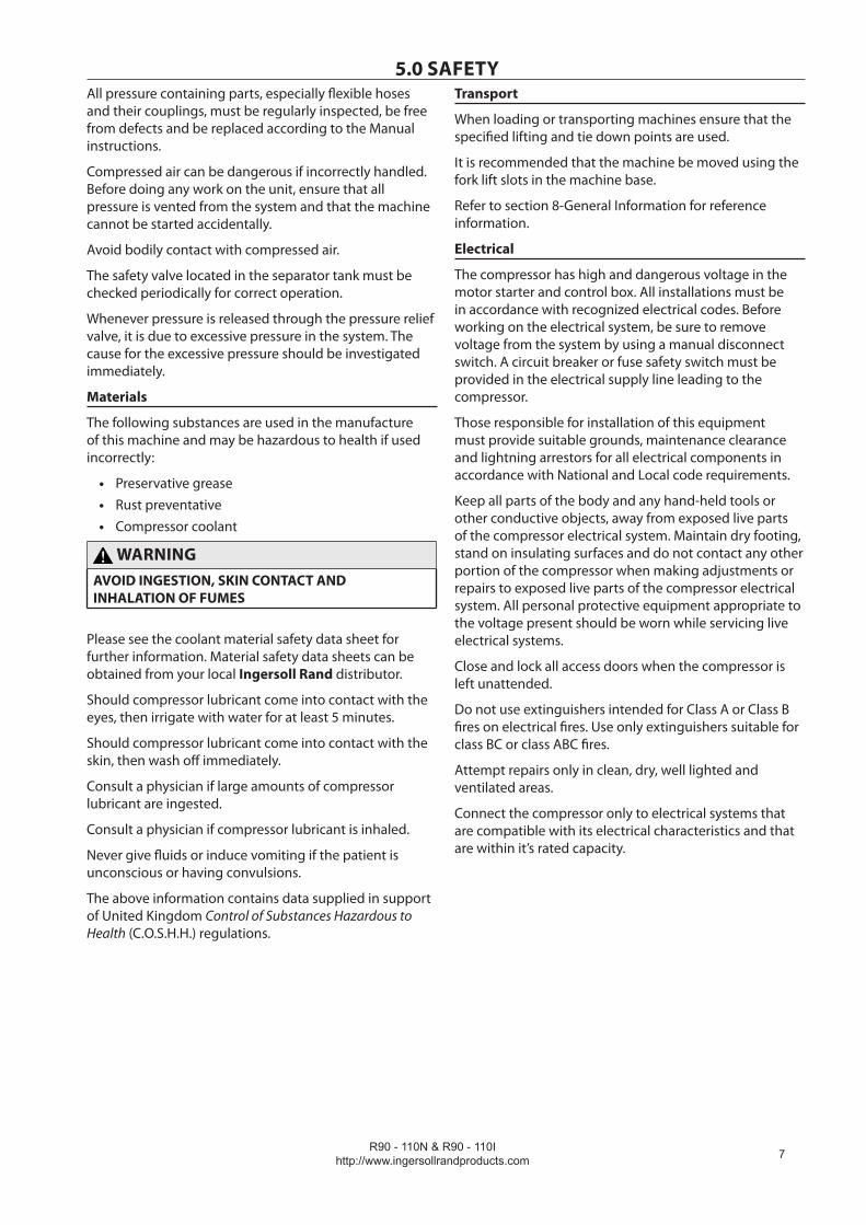
All pressure containing parts, especially flexible hoses and their couplings, must be regularly inspected, be free from defects and be replaced according to the Manual instructions.
Compressed air can be dangerous if incorrectly handled. Before doing any work on the unit, ensure that all pressure is vented from the system and that the machine cannot be started accidentally.
Avoid bodily contact with compressed air.
The safety valve located in the separator tank must be checked periodically for correct operation.
Whenever pressure is released through the pressure relief valve, it is due to excessive pressure in the system. The cause for the excessive pressure should be investigated immediately.
Materials
The following substances are used in the manufacture of this machine and may be hazardous to health if used incorrectly:
Preservative greaseRust preventativeCompressor coolant
WARNINGAVOID INGESTION, SKIN CONTACT AND INHALATION OF FUMES
Please see the coolant material safety data sheet for further information. Material safety data sheets can be obtained from your local Ingersoll Rand distributor.
Should compressor lubricant come into contact with the eyes, then irrigate with water for at least 5 minutes.
Should compressor lubricant come into contact with the skin, then wash off immediately.
Consult a physician if large amounts of compressor lubricant are ingested.
Consult a physician if compressor lubricant is inhaled.
Never give fluids or induce vomiting if the patient is unconscious or having convulsions.
The above information contains data supplied in support of United Kingdom Control of Substances Hazardous to Health (C.O.S.H.H.) regulations.
•••
Transport
When loading or transporting machines ensure that the specified lifting and tie down points are used.
It is recommended that the machine be moved using the fork lift slots in the machine base.
Refer to section 8-General Information for reference information.
Electrical
The compressor has high and dangerous voltage in the motor starter and control box. All installations must be in accordance with recognized electrical codes. Before working on the electrical system, be sure to remove voltage from the system by using a manual disconnect switch. A circuit breaker or fuse safety switch must be provided in the electrical supply line leading to the compressor.
Those responsible for installation of this equipment must provide suitable grounds, maintenance clearance and lightning arrestors for all electrical components in accordance with National and Local code requirements.
Keep all parts of the body and any hand-held tools or other conductive objects, away from exposed live parts of the compressor electrical system. Maintain dry footing, stand on insulating surfaces and do not contact any other portion of the compressor when making adjustments or repairs to exposed live parts of the compressor electrical system. All personal protective equipment appropriate to the voltage present should be worn while servicing live electrical systems.
Close and lock all access doors when the compressor is left unattended.
Do not use extinguishers intended for Class A or Class B fires on electrical fires. Use only extinguishers suitable for class BC or class ABC fires.
Attempt repairs only in clean, dry, well lighted and ventilated areas.
Connect the compressor only to electrical systems that are compatible with its electrical characteristics and that are within it’s rated capacity.
5.0 SAFETY
R90 - 110N & R90 - 110Ihttp://www.ingersollrandproducts.com
�
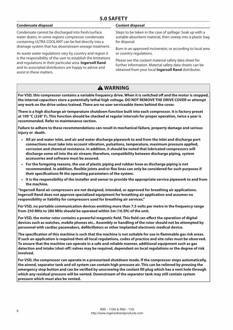
5.0 SAFETYCondensate disposal
Condensate cannot be discharged into fresh/surface water drains. In some regions compressor condensate containing ULTRA COOLANT can be fed directly into a drainage system that has downstream sewage treatment.
As waste water regulations vary by country and region it is the responsibility of the user to establish the limitations and regulations in their particular area. Ingersoll Rand and its associated distributors are happy to advise and assist in these matters.
Coolant disposal
Steps to be taken in the case of spillage: Soak up with a suitable absorbent material, then sweep into a plastic bag for disposal.
Burn in an approved incinerator, or according to local area or country regulations.
Please see the coolant material safety data sheet for further information. Material safety data sheets can be obtained from your local Ingersoll Rand distributor.
WARNINGFor VSD, this compressor contains a variable frequency drive. When it is switched off and the motor is stopped, the internal capacitors store a potentially lethal high voltage. DO NOT REMOVE THE DRIVE COVER or attempt any work on the drive unless trained. There are no user serviceable items behind the cover.
There is a high discharge air temperature shutdown function built into each compressor. It is factory preset at 109 °C (228° F). This function should be checked at regular intervals for proper operation, twice a year is recommended. Refer to maintenance section.
Failure to adhere to these recommendations can result in mechanical failure, property damage and serious injury or death.
All air and water inlet, and air and water discharge pipework to and from the inlet and discharge port connections must take into account vibration, pulsations, temperature, maximum pressure applied, corrosion and chemical resistance. In addition, it should be noted that lubricated compressors will discharge some oil into the air stream; therefore, compatibility between discharge piping, system accessories and software must be assured.For the foregoing reasons, the use of plastic piping and rubber hose as discharge piping is not recommended. In addition, flexible joints and/or flex lines can only be considered for such purposes if their specifications fit the operating parameters of the system.It is the responsibility of the installer and owner to provide the appropriate service pipework to and from the machine.
“Ingersoll Rand air compressors are not designed, intended, or approved for breathing air applications. Ingersoll Rand does not approve specialized equipment for breathing air application and assumes no responsibility or liability for compressors used for breathing air services.”
For VSD, no portable communication devices emitting more than 7.5 volts per metre in the frequency range from 250 MHz to 280 MHz should be operated within 5m (16.5ft) of the unit.
For VSD, the motor rotor contains a powerful magnetic field. This field can effect the operation of digital devices such as watches, mobile phones etc.. Assembly or handling of the rotor should not be attempted by personnel with cardiac pacemakers, defibrillators or other implanted electronic medical device.
The specification of this machine is such that the machine is not suitable for use in flammable gas risk areas. If such an application is required then all local regulations, codes of practice and site rules must be observed. To ensure that the machine can operate in a safe and reliable manner, additional equipment such as gas detection and intake (shut-off) valves may be required, dependant on local regulations or the degree of risk involved.
For VSD, the compressor can operate in a pressurized shutdown mode. If the compressor stops automatically, the airend, separator tank and oil system can contain high pressure air. This can be relieved by pressing the emergency stop button and can be verified by unscrewing the coolant fill plug which has a vent hole through which any residual pressure will be vented. Downstream of the separator tank may still contain system pressure which must also be vented.
•
•
•
R90 - 110N & R90 - 110Ihttp://www.ingersollrandproducts.com 9
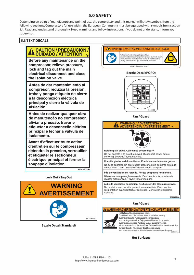
5.0 SAFETYDepending on point of manufacture and point of use, the compressor and this manual will show symbols from the following sections. Compressors for use within the European Community must be equipped with symbols from section 5.4. Read and understand thoroughly. Heed warnings and follow instructions. If you do not understand, inform your supervisor.
5.3 TEXT DECALS
32343907-B
Lock Out / Tag Out
Bezzle Decal (Standard)
WARNING / AVERTISSEMENT / ADVERTENCIA / AVISO
Machine restarts automatically after power failure.La machine redemarre automatiquement après une coupure de courant.La maquina arranca automaticamente despues de una falla electrica.Comença automaticamente apos interrupçao de eletricidade.
© ingersollrandproducts.com
Bezzle Decal (PORO)
93165959
Fan / Guard
WARNING / ADVERTENCIA /ADVERTÊNCIA / AVERTISSEMENT
Rotating fan blade. Can cause severe injury.Do not operate with guard removed. Disconnect power before servicing. Lockout/Tagout machine.
Cuchilla giratoria del ventilador. Puede causar lesiones graves.No debe operarse sin el protector. Desconecte la corriente antes de dar servicio. Cierre con candado y etiqueta la máquina.
Pás de ventilador em rotação. Perigo de graves ferimentos.Não opere com proteção removida. Desconecte a força antes de realizar manutenção. Travar/Rotular máquina.
Aube de ventilateur en rotation. Peut causer des blessures graves.Ne pas faire marcher si la protection a été retirée. Déconnecter l’alimentation avant d’effectuer l’entretien. Verrouiller/étiqueter la machine.
32343550-A
Fan / Guard
Hot Sufaces. Can cause serious injury. Do not touch any of the surfaces. Allow to cool before servicing.Superficie Caliente. Puede causar lesiones graves.No tocar ninguna superficie. Deje que se enfrie antes de dar servico.Superfícies Aquecidas. Ponderão causar graves ferimentos.Não tocar em nenhuma das superfícies. Deixar esfriar antes de realizar serviços.Surface Chaude. Peut causer des blessures graves. Ne toucher aucune surface. Attendre le refroidissement avant de réparer.
32343584-A
WARNING/ADVERTENCIA/ADVERTÊNCIA/AVERTISSEMENT
Hot Surfaces

R90 - 110N & R90 - 110Ihttp://www.ingersollrandproducts.com
10
5.0 SAFETY
Aire a alta presión. Puede causar lesiones personales severas o muerte.Alivie la presión antes de remover válaulas, tapones, acoples o cubiertas.
High pressure air. Can cause severe injury or death.Relieve pressure before removing filler plugs/caps, fittings, valves or covers.
Ar a alta pressão. Pode ser prejudicial à saúde ou causar morte.Aliviar a pressão antes de remover tampões, conexões, vávulas ou tampas.
Air à haute pression. Peut causer des blessures graves ou la mort.Détendre la pression avant de retirer les bouchons/capuchonsde remplissage, les raccords, les soupapes ou les couvercles.
32343527-A
WARNING / ADVERTENCIA /ADVERTÊNCIA / AVERTISSEMENT
Pressure Vessel
X-T
END
TM C O O L A N T
ON
LY
23540594-A
Coolant Cap X-Tend
Coolant Cap Ultra
93166460
Coolant Drain
2355
1559
-A
Remove shipping brace
High Voltage
93166478
Condensate Drain
R90 - 110N & R90 - 110Ihttp://www.ingersollrandproducts.com 11
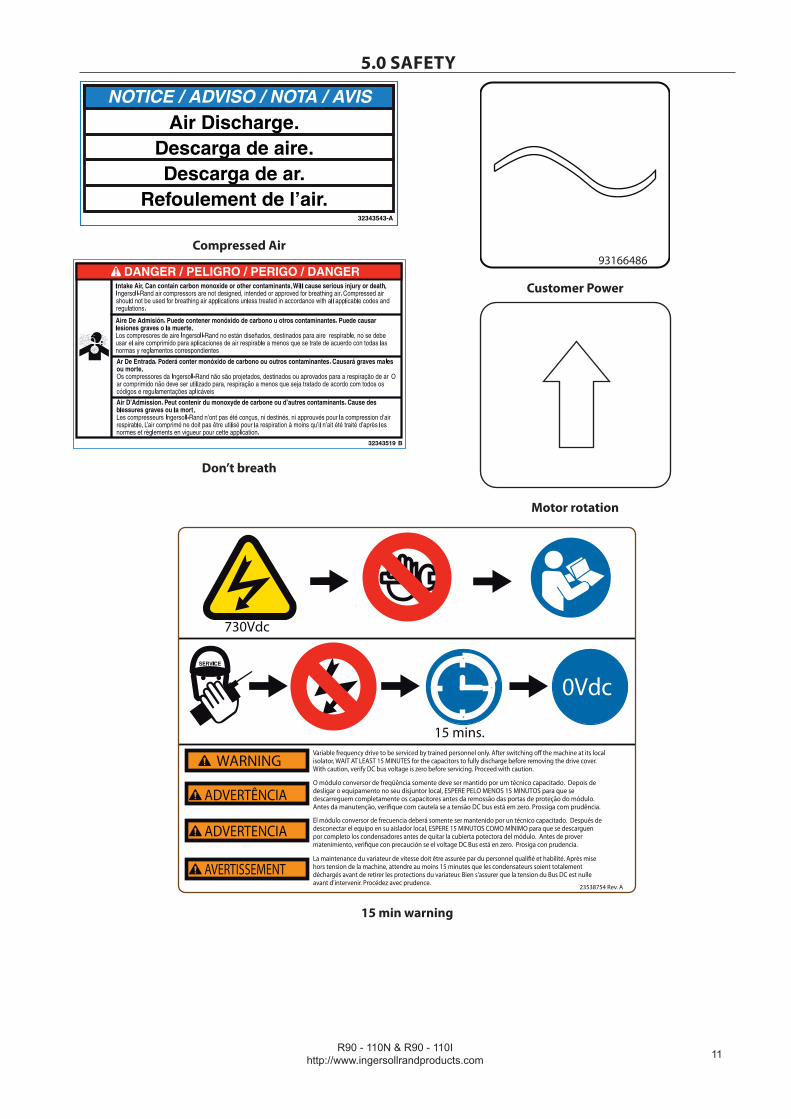
5.0 SAFETY
NOTICE / ADVISO / NOTA / AVISAir Discharge.
Descarga de aire.Descarga de ar.
Refoulement de l’air.32343543-A
Compressed Air
Don’t breath
93166486
Customer Power
Motor rotation
Variable frequency drive to be serviced by trained personnel only. After switching off the machine at its local isolator, WAIT AT LEAST 15 MINUTES for the capacitors to fully discharge before removing the drive cover. With caution, verify DC bus voltage is zero before servicing. Proceed with caution.
O módulo conversor de freqüência somente deve ser mantido por um técnico capacitado. Depois de desligar o equipamento no seu disjuntor local, ESPERE PELO MENOS 15 MINUTOS para que se descarreguem completamente os capacitores antes da remossão das portas de proteção do módulo. Antes da manutenção, verifique com cautela se a tensão DC bus está em zero. Prossiga com prudência.
El módulo conversor de frecuencia deberá somente ser mantenido por un técnico capacitado. Después de desconectar el equipo en su aislador local, ESPERE 15 MINUTOS COMO MÍNIMO para que se descarguen por completo los condensadores antes de quitar la cubierta potectora del módulo. Antes de prover matenimiento, verifique con precaución se el voltage DC Bus está en zero. Prosiga con prudencia.
23538754 Rev. A
WARNING
ADVERTÊNCIA
ADVERTENCIA
La maintenance du variateur de vitesse doit être assurée par du personnel qualifié et habilité. Après mise hors tension de la machine, attendre au moins 15 minutes que les condensateurs soient totalement déchargés avant de retirer les protections du variateur. Bien s'assurer que la tension du Bus DC est nulle avant d'intervenir. Procédez avec prudence.
AVERTISSEMENT
15 mins.
0Vdc
730Vdc
15 min warning
R90 - 110N & R90 - 110Ihttp://www.ingersollrandproducts.com
1�
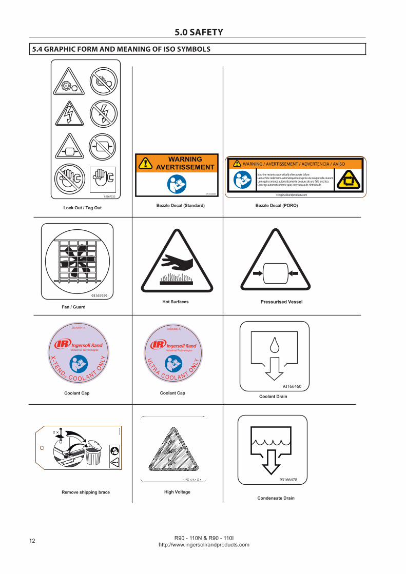
5.0 SAFETY
5.4 GRAPHIC FORM AND MEANING OF ISO SYMBOLS
Lock Out / Tag Out Bezzle Decal (Standard) Bezzle Decal (PORO)
Hot SurfacesFan / Guard
Pressurised Vessel
Coolant Drain
Remove shipping brace High Voltage
Coolant Cap Coolant Cap
.
X-T
EN
DTM C O O L A N T
ON
LY
23540594-A
2355
1559
-A
93165959
93166460
Condensate Drain
93166478
92867522
WARNING / AVERTISSEMENT / ADVERTENCIA / AVISO
Machine restarts automatically after power failure.La machine redemarre automatiquement après une coupure de courant.La maquina arranca automaticamente despues de una falla electrica.Comença automaticamente apos interrupçao de eletricidade.
© ingersollrandproducts.com

R90 - 110N & R90 - 110Ihttp://www.ingersollrandproducts.com 1�
5.0 SAFETY
Customer Power
Motor rotation
Compressed Air Don't breath
9316648692867498
IR Logo15 min warning
Variable frequency drive to be serviced by trained personnel only. After switching off the machine at its local isolator, WAIT AT LEAST 15 MINUTES for the capacitors to fully discharge before removing the drive cover. With caution, verify DC bus voltage is zero before servicing. Proceed with caution.
O módulo conversor de freqüência somente deve ser mantido por um técnico capacitado. Depois de desligar o equipamento no seu disjuntor local, ESPERE PELO MENOS 15 MINUTOS para que se descarreguem completamente os capacitores antes da remossão das portas de proteção do módulo. Antes da manutenção, verifique com cautela se a tensão DC bus está em zero. Prossiga com prudência.
El módulo conversor de frecuencia deberá somente ser mantenido por un técnico capacitado. Después de desconectar el equipo en su aislador local, ESPERE 15 MINUTOS COMO MÍNIMO para que se descarguen por completo los condensadores antes de quitar la cubierta potectora del módulo. Antes de prover matenimiento, verifique con precaución se el voltage DC Bus está en zero. Prosiga con prudencia.
23538754 Rev. A
WARNING
ADVERTÊNCIA
ADVERTENCIA
La maintenance du variateur de vitesse doit être assurée par du personnel qualifié et habilité. Après mise hors tension de la machine, attendre au moins 15 minutes que les condensateurs soient totalement déchargés avant de retirer les protections du variateur. Bien s'assurer que la tension du Bus DC est nulle avant d'intervenir. Procédez avec prudence.
AVERTISSEMENT
15 mins.
0Vdc
730Vdc

R90 - 110N & R90 - 110Ihttp://www.ingersollrandproducts.com
1�
6.0 RECEIPT / HANDLING
6.1 RECEIPT
When you receive the compressor please inspect it closely. Any indication of careless handling by the carrier should be noted on the delivery receipt especially if the compressor will not be immediately unpacked. Obtaining the delivery persons signed agreement to any noted damages will facilitate any future insurance claims.
IMPORTANTREAD THIS
LOST OR DAMAGED GOODS
THOROUGHLY INSPECT THIS SHIPMENT IMMEDIATELY UPON ARRIVAL
OUR RESPONSIBILITY FOR THIS SHIPMENT CEASED WHEN THE CARRIER SIGNEDBILL OF LADING
If goods are received short or in damaged condition, it is important that you notify the carrier and insist on anotation of the loss or damage across the face of the freight bill. Otherwise no claim can be enforced against the
transportation company.
If concealed loss or damage is discovered, notify your carrier at once and request an inspection. This is absolutelynecessary. Unless you do this the carrier will not entertain any claim for loss or damage. The agent will make an
inspection and grant a concealed damage notation. If you give the transportation company a clear receipt forgoods that have been damaged or lost in transit, you do so at your own risk and expense.
WE, AT lR, ARE WILLING TO ASSIST YOU IN EVERY POSSIBLE MANNER TO COLLECT CLAIMS FOR LOSSOR DAMAGE, BUT THE WILLINGNESS ON OUR PART DOES NOT MAKE US RESPONSIBLE FORCOLLECTION OF CLAIMS OR REPLACEMENT OF MATERIAL. THE ACTUAL FILING AND PROCESSING OFTHE CLAIM IS YOUR RESPONSIBILITY.
Ingersoll Rand Company
6.2 UNPACKING AND HANDLINGThe compressor will normally be delivered with a polyethylene or other cover. If a knife has to be used to remove this cover, ensure that the exterior paintwork of the compressor is not damaged.
Incorporated within the base of the compressor are slots to enable a fork lift truck to move the machine. Ensure truck forks are fully engaged on both sides. Alternatively a special lifting frame can be utilized to enable a crane or hoist to move the compressor. Use only marked lifting points.
Once the packaging and pallet are discarded and the unit is in its final position, remove the yellow painted following transit brackets from the resilient mounts and store for future use or discard:
For VSD
(3) brackets at the separator tank(1) bracket from the air end discharge elbow.(1) bracket from the air end support.
For FS
(3) brackets at the separator tank(1) bracket from the air end support.(1) bracket from the motor mounting bracket.
•••
•••
6.3 LONG TERM STORAGEIf the compressor will not be commissioned within 6 months of receipt, the compressor should be prepared for long term storage. Please contact your local Ingersoll Rand distributor for details
R90 - 110N & R90 - 110Ihttp://www.ingersollrandproducts.com
1�
7.0 INSTALLATION
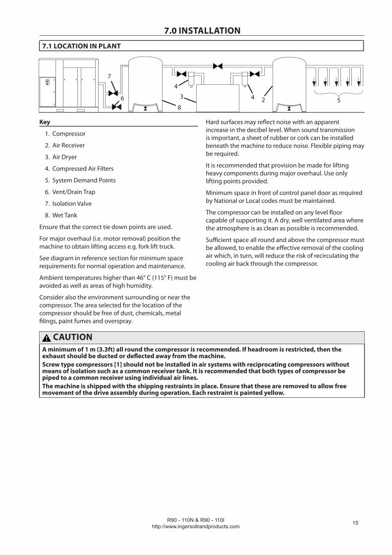
7.1 LOCATION IN PLANT
52436
8
7
4
Key
Compressor
Air Receiver
Air Dryer
Compressed Air Filters
System Demand Points
Vent/Drain Trap
Isolation Valve
Wet Tank
Ensure that the correct tie down points are used.
For major overhaul (i.e. motor removal) position the machine to obtain lifting access e.g. fork lift truck.
See diagram in reference section for minimum space requirements for normal operation and maintenance.
Ambient temperatures higher than 46° C (115° F) must be avoided as well as areas of high humidity.
Consider also the environment surrounding or near the compressor. The area selected for the location of the compressor should be free of dust, chemicals, metal filings, paint fumes and overspray.
1.
2.
3.
4.
5.
6.
7.
8.
Hard surfaces may reflect noise with an apparent increase in the decibel level. When sound transmission is important, a sheet of rubber or cork can be installed beneath the machine to reduce noise. Flexible piping may be required.
It is recommended that provision be made for lifting heavy components during major overhaul. Use only lifting points provided.
Minimum space in front of control panel door as required by National or Local codes must be maintained.
The compressor can be installed on any level floor capable of supporting it. A dry, well ventilated area where the atmosphere is as clean as possible is recommended.
Sufficient space all round and above the compressor must be allowed, to enable the effective removal of the cooling air which, in turn, will reduce the risk of recirculating the cooling air back through the compressor.
CAUTIONA minimum of 1 m (3.3ft) all round the compressor is recommended. If headroom is restricted, then the exhaust should be ducted or deflected away from the machine.Screw type compressors [1] should not be installed in air systems with reciprocating compressors without means of isolation such as a common receiver tank. It is recommended that both types of compressor be piped to a common receiver using individual air lines.The machine is shipped with the shipping restraints in place. Ensure that these are removed to allow free movement of the drive assembly during operation. Each restraint is painted yellow.
R90 - 110N & R90 - 110Ihttp://www.ingersollrandproducts.com
1�
7.0 INSTALLATION
7.2 DISCHARGE AND CONDENSATE PIPING
52436
8
7
4
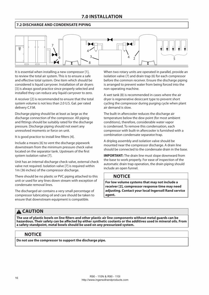
It is essential when installing a new compressor [1], to review the total air system. This is to ensure a safe and effective total system. One item which should be considered is liquid carryover. Installation of air dryers [3] is always good practice since properly selected and installed they can reduce any liquid carryover to zero.
A receiver [2] is recommended to ensure that the total system volume is not less than 2.0 U.S. Gal. per rated delivery C.F.M.
Discharge piping should be at least as large as the discharge connection of the compressor. All piping and fittings should be suitably rated for the discharge pressure. Discharge piping should not exert any unresolved moments or force on unit.
It is good practice to install line filters [4].
Include a means [6] to vent the discharge pipework downstream from the minimum pressure check valve located on the separator tank. Upstream of the first system isolation valve [7].
Unit has an internal discharge check valve, external check valve not required. Isolation valve [7] is required within 1m (36 inches) of the compressor discharge.
There should be no plastic or PVC piping attached to this unit or used for any lines down stream with exception of condensate removal lines.
The discharged air contains a very small percentage of compressor lubricating oil and care should be taken to ensure that downstream equipment is compatible.
When two rotary units are operated in parallel, provide an isolation vaIve (7) and drain trap (6) for each compressor before the common receiver. Ensure the discharge piping is arranged to prevent water from being forced into the non-operating machine.
A wet tank (8) is recommended in cases where the air dryer is regenerative desiccant type to prevent short cycling the compressor during purging cycle when plant air demand is slow.
The built-in aftercooler reduces the discharge air temperature below the dew point (for most ambient conditions), therefore, considerable water vapor is condensed. To remove this condensation, each compressor with built-in aftercooler is furnished with a combination condensate separator/trap.
A dripleg assembly and isolation valve should be mounted near the compressor discharge. A drain line should be connected to the condensate drain in the base.
IMPORTANT: The drain line must slope downward from the base to work properly. For ease of inspection of the automatic drain trap operation, the drain piping should include an open funnel.
NOTICEFor low volume systems that may not include a receiver [2], compressor response time may need adjusting. Contact your local Ingersoll Rand service agent.
CAUTIONThe use of plastic bowls on line filters and other plastic air line components without metal guards can be hazardous. Their safety can be affected by either synthetic coolants or the additives used in mineral oils. From a safety standpoint, metal bowls should be used on any pressurized system.
NOTICEDo not use the compressor to support the discharge pipe.
R90 - 110N & R90 - 110Ihttp://www.ingersollrandproducts.com
1�
7.0 INSTALLATION
7.3 ELECTRICAL
CAUTIONThis procedure should only be carried out by a qualified electrician, electrical contractor or your local Ingersoll Rand Distributor or Customer Center.
The compressor should be properly grounded / earthed in accordance with Local and National Code requirements.
Installation of this compressor must be in accordance with recognized electrical codes and any local Health and Safety Codes.
The compressor must have its own isolator situated adjacent to it. The fuse protecting the circuit and the compressor must be selected in accordance with local and national code requirements on the basis of the data provided in the general information section
Feeder cables should be sized by the customer/electrical contractor to ensure that the circuit is balanced and not overloaded by other electrical equipment. The length of wiring from a suitable electrical feed point is critical as voltage drops may impair the performance of the compressor.
For VSD, cable sizes may vary considerably so the line reactor is equipped with copper bus connections. These connections can accept bolts between 6mm and 12mm.
Feeder cable connections to incoming terminals L1-L2-L3 should be tight and clean.
The applied voltage must be compatible with the compressor data plate ratings.
The control circuit transformer has different voltage tappings. Ensure that these are set for the specific applied voltage prior to starting.
A hole with removable blind plate is provided for incoming power connection. Remove blind plate to cut hole as required. If it is necessary to make a hole in the control box in a different location, care should be taken to not allow metal shavings to enter the starter and other electrical components within the box. If another hole is used, the original hole must be blocked off.
The feeder cable must be suitably glanded in to the starter box to maintain proper ingress protection. Fixed speed starter boxes are rated for NEMA4/IP65, and VSD starter boxes are rated for NEMA12/IP54. For VSD starter boxes, the feeder cable must be glanded to ensure that dirty air does not by-pass the filters.
On completion of electrical installation, check that blower or fan motor rotation is correct.
For VSD, this machine is designed for use, where the electricity supply is separated from nearby residential and commercial areas. If the machine is to be used in the light industrial, residential or commercial environment where the local supply network is shared, further radio frequency (RF) screening measures may be required. Consult your local distributor/supplier for details of the optional RF filter.
For VSD, the compressor has a anti-condensation heater and thermostat in the electrical box. This circuit can be connected to an independent electrical supply of either 110V or 230V single phase, dependant on the country of installation. The supply should be suitably fused and an independent isolator installed adjacent to the compressor. Verify that thermostat is adjusted to 85˚F (29˚C). This should be done in accordance with local and national codes. It is good practice and sometimes mandatory, to display suitable signs warning that the machine has two separate electrical supplies which both must be isolated before any work is attempted.
For VSD, alternately the heater circuit can be supplied from the 110V tapping of the control transformer and connected as shown on schematic wiring diagram.
CAUTIONNever test the insulation resistance of any part of the machines electrical circuits, including the motor without completely disconnecting the following.
Primary side of control power transformerInput power and motor cables from soft starter (if equipped)Input power and motor cables from the main VSD (if equipped)Input power and motor cables from the blower VSD (if equipped)
••
•
•
NOTICEMain and fan motor insulation must be tested by the competant electrician prior to initial Start-up or following an extended shutdown period in cold damp conditions.
R90 - 110N & R90 - 110Ihttp://www.ingersollrandproducts.com
1�
7.0 INSTALLATION
CAUTIONVERY IMPORTANT (For VSD only)
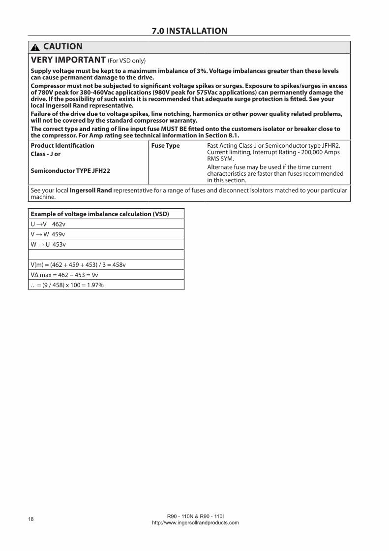
Supply voltage must be kept to a maximum imbalance of 3%. Voltage imbalances greater than these levels can cause permanent damage to the drive.Compressor must not be subjected to significant voltage spikes or surges. Exposure to spikes/surges in excess of 780V peak for 380-460Vac applications (980V peak for 575Vac applications) can permanently damage the drive. If the possibility of such exists it is recommended that adequate surge protection is fitted. See your local Ingersoll Rand representative.Failure of the drive due to voltage spikes, line notching, harmonics or other power quality related problems, will not be covered by the standard compressor warranty.The correct type and rating of line input fuse MUST BE fitted onto the customers isolator or breaker close to the compressor. For Amp rating see technical information in Section 8.1.
Product IdentificationClass - J or
Semiconductor TYPE JFH22
Fuse Type Fast Acting Class-J or Semiconductor type JFHR2, Current limiting, Interrupt Rating - 200,000 Amps RMS SYM.Alternate fuse may be used if the time current characteristics are faster than fuses recommended in this section.
See your local Ingersoll Rand representative for a range of fuses and disconnect isolators matched to your particular machine.
Example of voltage imbalance calculation (VSD)
U →V 462v
V → W 459v
W → U 453v
V(m) = (462 + 459 + 453) / 3 = 458v
VΔ max = 462 − 453 = 9v
... = (9 / 458) x 100 = 1.97%

R90 - 110N & R90 - 110Ihttp://www.ingersollrandproducts.com
19
7.0 INSTALLATION
7.4 WATERCOOLED UNITS
Cooling Water Piping
Water piping to and from the compressor package must be at least as big as the package connection size, or larger. Do NOT undersize the water piping!
Isolation valves with side drains should be installed on both the inlet and outlet lines. To maintain cooler cleanliness and reliability, it is important to install a strainer of 2mm mesh size on the inlet line. Strainers are available from Ingersoll Rand.
For sea water applications (sea water option only) a zinc anode is NOT recommended as it will deteriorate the copper oxide film on the 70/30 Copper-Nickel alloy tubes in contact with sea water. To minimize galvanic corrosion and provide the greatest corrosion protection to your coolers, it is strongly recommended that a section of iron pipe (>300mm length) be connected as close as possible to the air compressor package water inlet connection. The iron pipe will act as the sacrificial anode for the Copper-Nickel tubes and therefore must be considered a regular maintenance & replacement item. For this reason the section of iron pipe should be installed so that it can be easily replaced (i.e.: with a union joint).
The air compressor has a normally closed solenoid valve that is fitted to the water outlet side, within the package. The valve is wired into the air compressor control circuit and closes when the compressor stops.
Carefully inspect your water system before installing the air compressor package. Ensure that the piping is free of scale and deposits that may restrict water flow to the air compressor package. If water cleanliness is poor, filtration installed on your water inlet pipe line is recommended.
Proper operation of your compressor requires that the cooling water flow listed below be provided at a maximum supply temperature of 46° C (115° F). Please see the compressor engineering data sheets for cooling water flow rates.
CAUTIONIf you have a Harsh Water air compressor option and you are using sea water or brackish water as the cooling medium, DO NOT exceed the water flow values listed on the compressor’s engineering data sheets. Salts are very abrasive and their ability to erode the heat exchanger tubes increase significantly as the water velocity (flow) increases. It is recommended that the pipe fitter or engineer responsible for the supply piping include an appropriately sized flow control device such as an orifice to limit the maximum potential flow to the air compressor. Effects of erosion or corrosion are specifically excluded from warranty considerations.
Water temperature and pressure gauges should be installed in the water piping for use in any fault finding of the water system. Water pressure should ideally be between 3 and 5 bar (43.5 and 72.5 psi) but must not be above 10 bar (145 psi)
Water cleanliness is also extremely important. Cleaning of coolers as a result of fouling is a customer responsibility. Therefore, it is highly recommended that proper water quality must meet the requirements listed in WATER QUALITY RECOMMENDATIONS later in this section.
Venting the water system
Air should be vented from the water side of the system to avoid poor performance and water hammer. Since the air compressor uses different type heat exchangers depending on your selection of “fresh water cooled” or “Harsh water cooled” system, the venting procedure is different. Be sure to use the correct procedure below.
Fresh water coolers (brazed plate heat exchangers):
1. Disconnect the water stop valve in the water outlet line of the compressor.
2. Open the inlet water valve(s) to allow the water to flow to the package.
3. Allow all the air to escape from the system and water is observed at the water outlet port.
4. Connect the water stop valve.
5. The system is now vented.
Harsh water coolers (shell & tube heat exchangers):
1. Locate the water system vent cocks on top of the aftercooler and oil cooler.
2. Open the water valve(s) allowing water to flow to the package.
3. Open the vent cocks and allow all air to escape from the system. When water is observed at the vent cocks, close them.
4. The system is now vented.
Draining the water system
Should it become necessary to completely drain the water system, use the following procedures specific to the water cooled option you have.
Fresh water coolers (brazed plate heat exchangers):
1. Disconnect the inlet water line from the connection located at the rear of the unit.
2. Disconnect the water stop valve in the water outlet line of the compressor.
3. Allow the system to completely drain.
R90 - 110N & R90 - 110Ihttp://www.ingersollrandproducts.com
�0
7.0 INSTALLATI ONHarsh water coolers (shell & tube heat exchangers):
1. Disconnect the inlet and discharge water lines from the connections located at the rear of the unit.
2. Locate the aftercooler and oil cooler. Remove the drain plugs located at the bottom of the coolers.
3. Open the vent ports in the top of the aftercooler and oil cooler
4. Allow the system to completely drain.
Adjusting the Aftercooler Trim Valve
See piping and instrumentation diagram (Section 8.3). The coolers are piped in a “parallel” water flow arrangement with a manual trim valve controlling the flow through the aftercooler. The Aftercooler Trim Valve is factory set and should not need adjusting but if disturbed use following procedure.
1. Close valve fully clockwise and then open 2 full turns.
2. With the machine running loaded observe the pack-age discharge temperature on the Intellisys display. It should be approximately 15° F (8° C) above the water inlet temperature.
3. If the temperature is too high, open the valve ¼ turn and wait 1 minute. If the temperature is too low, close the valve ¼ turn and wait 1 minute. Repeat the incre-mental movements until the desired temperature is reached.
4. Put a “Warning − Do Not Adjust” label on the valve or fit a lock.
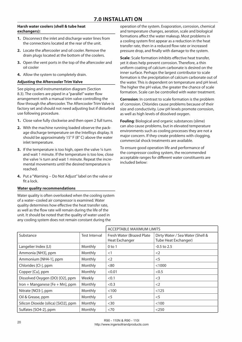
Water quality recommendations
Water quality is often overlooked when the cooling system of a water−cooled air compressor is examined. Water quality determines how effective the heat transfer rate, as well as the flow rate will remain during the life of the unit. It should be noted that the quality of water used in any cooling system does not remain constant during the
operation of the system. Evaporation, corrosion, chemical and temperature changes, aeration, scale and biological formations affect the water makeup. Most problems in a cooling system first appear as a reduction in the heat transfer rate, then in a reduced flow rate or increased pressure drop, and finally with damage to the system.
Scale: Scale formation inhibits effective heat transfer, yet it does help prevent corrosion. Therefore, a thin uniform coating of calcium carbonate is desired on the inner surface. Perhaps the largest contributor to scale formation is the precipitation of calcium carbonate out of the water. This is dependent on temperature and pH level. The higher the pH value, the greater the chance of scale formation. Scale can be controlled with water treatment.
Corrosion: In contrast to scale formation is the problem of corrosion. Chlorides cause problems because of their size and conductivity. Low pH levels promote corrosion, as well as high levels of dissolved oxygen.
Fouling: Biological and organic substances (slime) can also cause problems, but in elevated temperature environments such as cooling processes they are not a major concern. If they create problems with clogging, commercial shock treatments are available.
To ensure good operation life and performance of the compressor cooling system, the recommended acceptable ranges for different water constituents are included below:
ACCEPTABLE MAXIMUM LIMITS
Substance Test Interval Fresh Water (Brazed Plate Heat Exchanger
Dirty Water / Sea Water (Shell & Tube Heat Exchanger)
Langelier Index (LI) Monthly 0 to 1 -0.5 to 2.5
Ammonia [NH3], ppm Monthly <1 <2
Ammonium [NH4-1], ppm Monthly <2 <5
Chlorides [Cl-], ppm Monthly <80 <1000
Copper [Cu], ppm Monthly <0.01 <0.5
Dissolved Oxygen (DO) [O2], ppm Weekly <0.1 <3
Iron + Manganese [Fe + Mn], ppm Monthly <0.3 <2
Nitrate [NO3-], ppm Monthly <100 <125
Oil & Grease, ppm Monthly <5 <5
Silicon Dioxide (silica) [SiO2], ppm Monthly <30 <100
Sulfates [SO4-2], ppm Monthly <70 <250

R90 - 110N & R90 - 110Ihttp://www.ingersollrandproducts.com
�1
7.0 INSTALLATION
7.5 ENVIRONMENTAL LIMITS
The standard compressor package is designed for the following conditions:
Indoors onlyArea not considered to be a high dust area.Ambient temperature range 2 to 46oC (35-115oF)
Ingersoll Rand offers the following options for fixed speed units that extend the environmental limits:
Outdoor modificationLow ambient option(-23 to 46oC / -15 to 115oF)High ambient option (2 to 55oC)High dust air filterHigh dust package filter.
•••
•••••

R90 - 110N & R90 - 110Ihttp://www.ingersollrandproducts.com
��
8.0 GENERAL INFORMATION
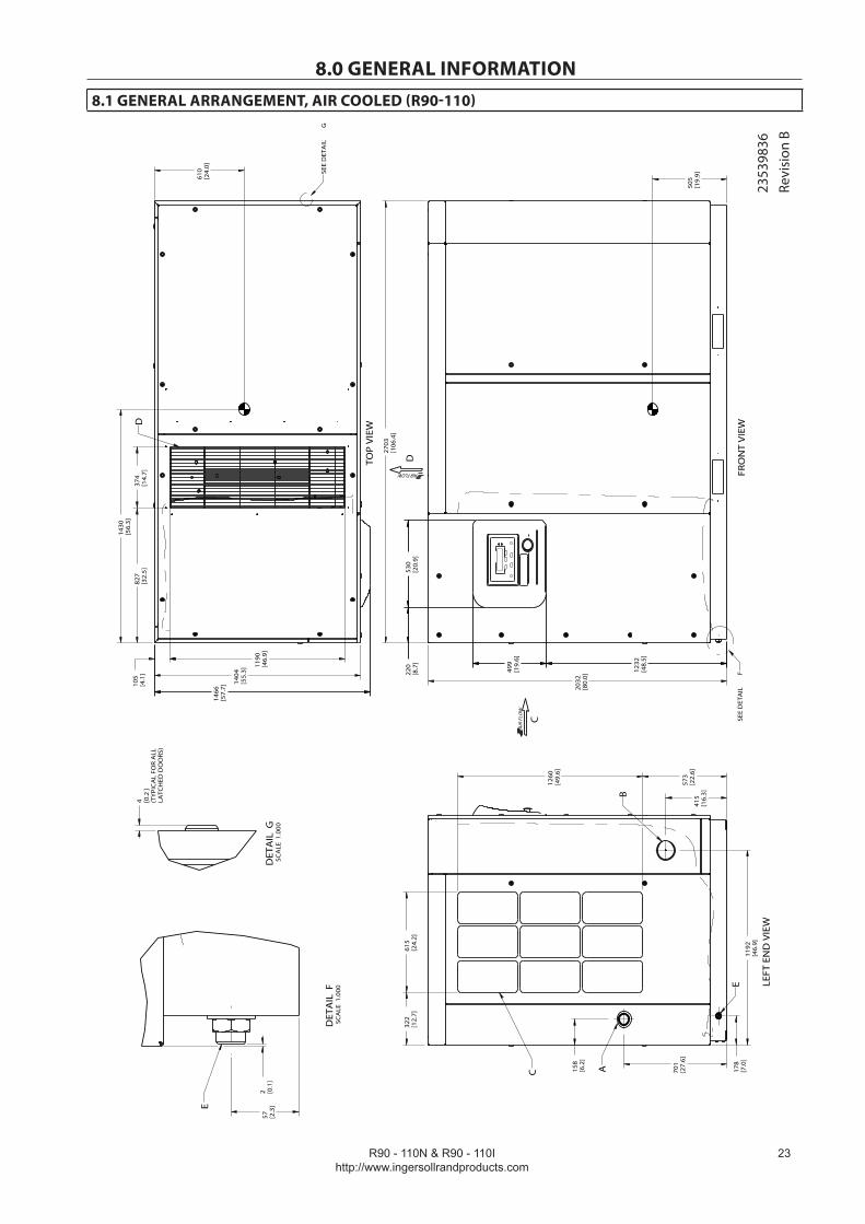
8.1 GENERAL ARRANGEMENT, AIR COOLED (R90-110)
FRONT
LEFT END
RIGHT END
TOP
REAR23539836Revision B
R90 - 110N & R90 - 110Ihttp://www.ingersollrandproducts.com
��
8.0 GENERAL INFORMATION8.1 GENERAL ARRANGEMENT, AIR COOLED (R90-110)
636,5
4
2703
[106
.4]
2032
[80.
0]
1404
[55.
3]
1466
[57.
7]105
[4.1
]
1190
[46.
9]
827
[32.
5]37
4[1
4.7]
573
[22.
6]
1260
[49.
6]
322
[12.
7]61
5[2
4.2]
178
[7.0
]
158
[6.2
]
1192
[46.
9]
415
[16.
3]
701
[27.
6]
220
[8.7
]53
0[2
0.9]
1232
[48.
5]
499
[19.
6]
2 [0.1
]57 [2
.3]
(TY
PIC
AL
FOR
ALL
LATC
HED
DO
ORS
)
4 0.2
[]
610
[24.
0]
1430
[56.
3]
505
[19.
9]
SEE
DET
AIL
FFR
ON
T V
IEW
C
D
SEE
DET
AIL
G
TOP
VIE
WD
LEFT
EN
D V
IEW
B
E
C A
DET
AIL
FSC
ALE
1.0
00
E
DET
AIL
GSC
ALE
1.0
00
AIR FLOW
AIR
FLO
W
2353
9836
Revi
sion
B
R90 - 110N & R90 - 110Ihttp://www.ingersollrandproducts.com
��
8.0 GENERAL INFORMATION
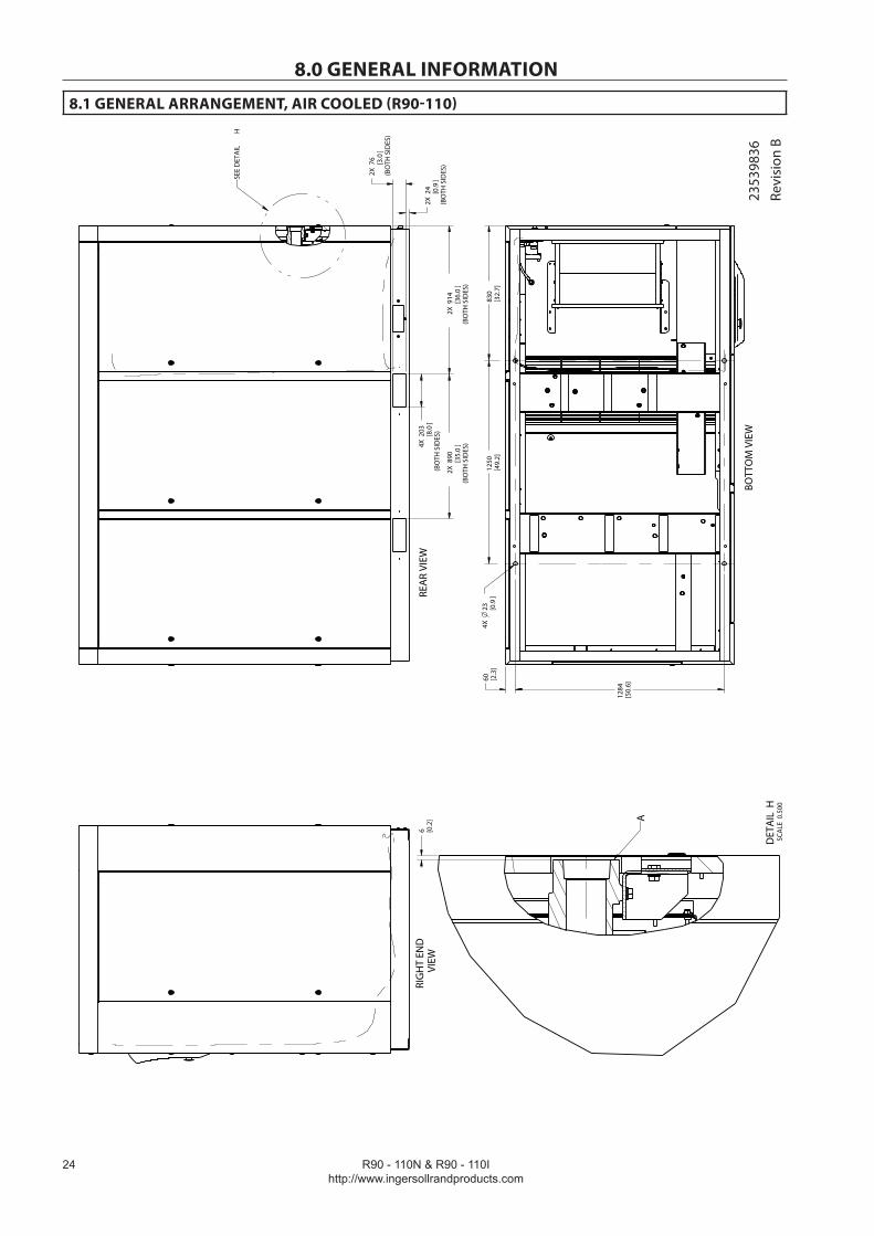
8.1 GENERAL ARRANGEMENT, AIR COOLED (R90-110)
18,579
636,54
18,579
2X
(BO
TH S
IDES
)
914
36.0
[]
4X
(BO
TH S
IDES
)203
8.0
[]
2X
(BO
TH S
IDES
)
890
35.0
[]
2X (BO
TH S
IDES
)
24 0.9
[]
2X (BO
TH S
IDES
)
76 3.0
[]
830
[32.
7]12
50[4
9.2]
1284
[50.
6]
60 [2.3
]4X
23 0.9
[]
6 [0.2
]
SEE
DET
AIL
H
REA
R VI
EW
BOTT
OM
VIE
W
RIG
HT
END
VIEW
DET
AIL
HSC
ALE
0.5
00
A
2353
9836
Revi
sion
B

R90 - 110N & R90 - 110Ihttp://www.ingersollrandproducts.com
��
8.0 GENERAL INFORMATION
8.1 GENERAL ARRANGEMENT WITH OPTIONAL OUTDOOR MODIFICATION (NOT AVAILABLE ON VSD UNITS)
1860
[73.
2]
395
[15.
6]
93 [3.7
]12
13[4
7.8]
580
[22.
8]
1232
[48.
5]
322
[12.
7]61
5[2
4.2]
2427
[95.
6]
801
[31.
6]
2744
[108
.0]
FRO
NT
LEFT
EN
D
C
D
FRO
NT
VIEW
RIG
HT
END
VIEW
LEFT
EN
DVI
EW
AIR
FLO
W
AIR
FLO
W
2353
9836
Revi
sion
B

R90 - 110N & R90 - 110Ihttp://www.ingersollrandproducts.com
��
8.0 GENERAL INFORMATION
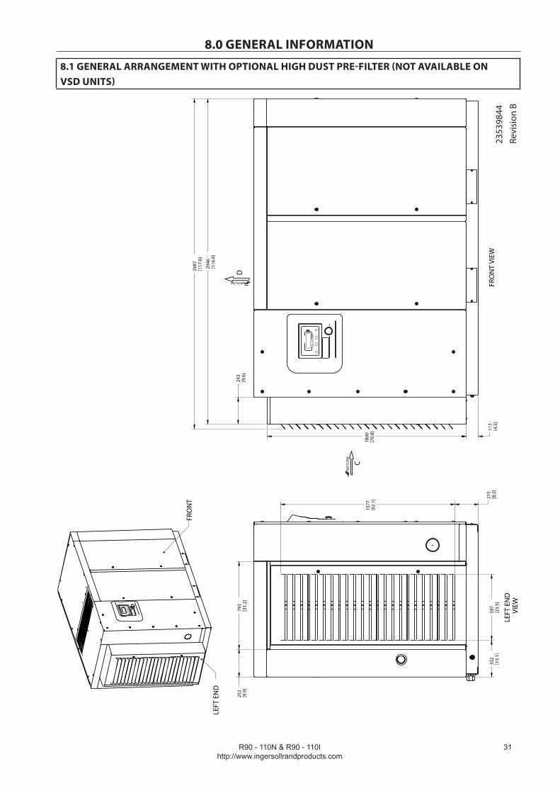
8.1 GENERAL ARRANGEMENT WITH OPTIONAL HIGH DUST PRE-FILTER (NOT AVAILABLE ON VSD UNITS)
243
[9.6
]
2946
[116
.0]
2987
[117
.6]
252
[9.9
]79
3[3
1.2]
332
[13.
1]59
7[2
3.5]
215
[8.5
]
1577
[62.
1]
113
[4.5
]
1800
[70.
8]
FRO
NT
LEFT
EN
D
C
D
FRO
NT
VIEW
LEFT
EN
DVI
EWAIR FLOW
AIR
FLO
W
2353
9836
Revi
sion
B
R90 - 110N & R90 - 110Ihttp://www.ingersollrandproducts.com
��
8.0 GENERAL INFORMATION
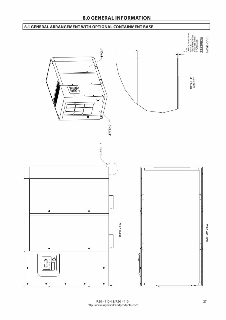
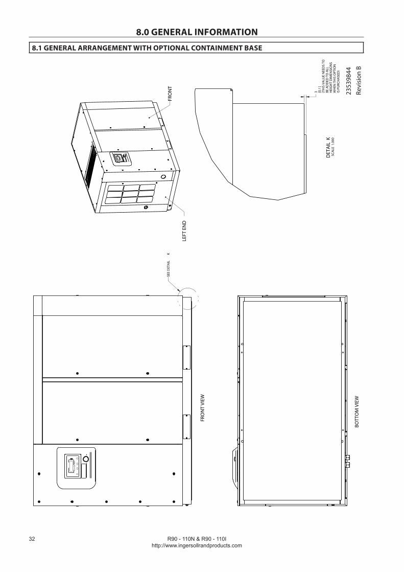
8.1 GENERAL ARRANGEMENT WITH OPTIONAL CONTAINMENT BASE
(TH
IS V
ALU
E N
EED
S TO
BE A
DD
ED T
O A
LLH
EIG
HT
DIM
ENSI
ON
SW
HEN
TH
IS O
PTIO
NIS
PU
RCH
ASE
D)
3 0.1
[]
SEE
DET
AIL
K
FRO
NT
VIEW
BOTT
OM
VIE
W
FRO
NT
LEFT
EN
D
DET
AIL
KSC
ALE
1.0
00
2353
9836
Revi
sion
B
R90 - 110N & R90 - 110Ihttp://www.ingersollrandproducts.com
��
8.0 GENERAL INFORMATION
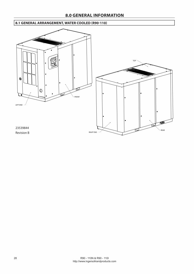
8.1 GENERAL ARRANGEMENT, WATER COOLED (R90-110)
636,54
FRONT
LEFT END
RIGHT END
TOP
REAR23539844Revision B

R90 - 110N & R90 - 110Ihttp://www.ingersollrandproducts.com
�9
8.0 GENERAL INFORMATION
8.1 GENERAL ARRANGEMENT, WATER COOLED (R90-110)
636,54
2703
[106
.4]
2032
[80.
0]
1404
[55.
3]
1466
[57.
7]105
[4.1
]
1190
[46.
9]
827
[32.
5]37
4[1
4.7]
573
[22.
6]
1260
[49.
6]
322
[12.
7]61
5[2
4.2]
178
[7.0
]
158
[6.2
]
1192
[46.
9]
415
[16.
3]
701
[27.
6]
220
[8.7
]53
0[2
0.9]
1232
[48.
5]
499
[19.
6]
2 [0.1
]57 [2
.3]
(TYP
ICA
L FO
R A
LLLA
TCH
ED D
OO
RS)
4 0.2
[]
750
[29.
5]
1460
[57.
5]
490
[19.
3]
SEE
DET
AIL
KFR
ON
T VI
EW
C
D
SEE
DET
AI L
L
TOP
VIEW
D
LEFT
EN
D V
IEW
B
E
C A
DET
AIL
KSC
ALE
1.0
00
E
DET
AIL
LSC
ALE
1.0
00
AIR FLOW
AIR
FLO
W
2353
9844
Revi
sion
B

R90 - 110N & R90 - 110Ihttp://www.ingersollrandproducts.com
�0
8.0 GENERAL INFORMATION
8.1 GENERAL ARRANGEMENT, WATER COOLED (R90-110)
636,54
2X
(BO
TH S
IDES
)
914
36.0
[]
4X
(BO
TH S
IDES
)203
8.0
[]
2X
(BO
TH S
IDES
)
890
35.0
[]
2X (BO
TH S
IDES
)
24 0.9
[]
2X (BO
TH S
IDES
)
76 3.0
[]
830
[32.
7]12
50[4
9.2]
1284
[50.
6]
60 [2.3
]4X
23 0.9
[]
6 [0.2
]
527
[20.
7]93 [3
.7]
70 [2.8
]
(50
Hz
- BSP
T)
32 1.2
[]
(60
Hz
- NPT
)
22 0.9
[]
SEE
DET
AIL
H
REA
R VI
EW
GF
BOTT
OM
VIE
W
RIG
HT
END
VIEW
SEE
DET
AIL
M
DET
AIL
HSC
ALE
0.3
75
A
DET
AIL
MSC
ALE
0.5
00
2353
9844
Revi
sion
B
R90 - 110N & R90 - 110Ihttp://www.ingersollrandproducts.com
�1
8.0 GENERAL INFORMATION
8.1 GENERAL ARRANGEMENT WITH OPTIONAL HIGH DUST PRE-FILTER (NOT AVAILABLE ONVSD UNITS)
243
[9.6
]
2946
[116
.0]
2987
[117
.6]
252
[9.9
]79
3[3
1.2]
332
[13.
1]59
7[2
3.5]
215
[8.5
]
1577
[62.
1]
113
[4.5
]
1800
[70.
8]
FRO
NT
LEFT
EN
D
C
D
FRO
NT
VIEW
LEFT
EN
DVI
EWAIR FLOW
AIR
FLO
W
2353
9844
Revi
sion
B
R90 - 110N & R90 - 110Ihttp://www.ingersollrandproducts.com
��
8.0 GENERAL INFORMATION
8.1 GENERAL ARRANGEMENT WITH OPTIONAL CONTAINMENT BASE
(TH
IS V
ALU
E N
EED
S TO
BE A
DD
ED T
O A
LLH
EIG
HT
DIM
ENSI
ON
SW
HEN
TH
IS O
PTIO
NIS
PU
RCH
ASE
D)
3 0.1
[]
SEE
DET
AIL
K
FRO
NT
VIEW
BOTT
OM
VIE
W
FRO
NT
LEFT
EN
D
DET
AIL
KSC
ALE
1.0
00
2353
9844
Revi
sion
B

R90 - 110N & R90 - 110Ihttp://www.ingersollrandproducts.com
��
8.0 GENERAL INFORMATION
8.2 PROCESS AND INSTRUMENTATION DIAGRAM (AC/WC) 90-160 KW (VSD)
23
4
5
67
9B
10
12
14
15
16
17
18
19
23
26 27
T
2821
8
P
P
31
PV
M
32
T
T33
35
34
36
T
13
37
T11
9AP
30
P 1
CUST
. AIR
TREA
TMEN
T
38
29
20
T
22
2nd
23 M
1st
40
41
P
2
TWO
STA
GE
ON
LY
25
M39
WC
25
M24
AC
2337
1677
Re
visi
on D
R90 - 110N & R90 - 110Ihttp://www.ingersollrandproducts.com
��
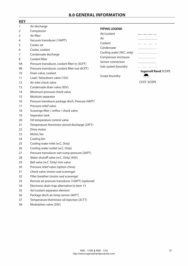
8.0 GENERAL INFORMATIONKEY1 Air discharge2 Compressor3 Air filter4 Vacuum transducer (1AVPT)5 Cooler, air6 Cooler, coolant7 Condensate discharge8 Coolant filter (s)9A Pressure transducer, coolant filter out (5CPT)9B Pressure transducer, coolant filter out (6CPT)10 Drain valve, coolant11 Oil cooler out temperature sensor 3CTT (Air cooled only)12 Air inlet/check valve13 Electronic no loss condensate drain14 Minimum pressure check valve15 Moisture separator16 Pressure transducer package disch. Press. (4APT)17 Pressure relief valve18 Scavenge filter / orifice / check valve19 Separator tank20 Oil temperature control valve21 Temperature airend discharge (2ATT)22 Blowdown solenoid valve 3SV23 Drive motor - variable speed24 Motor, blower - variable speed25 Cooling air blower26 Cooling water inlet (W.C. ONLY)27 Cooling water outlet (W.C. ONLY)28 Pressure transducer wet sump pressure (3APT)29 Pressure relief valve (OPTION CHINA)30 Remote air pressure transducer 9APT (optional)31 Water shutoff valve 4SV (W.C.ONLY)32 Package discharge air temperature sensor 4ATT33 Injected coolant temperature sensor 2CTT34 Orifice, seal scavenge air supply35 Seal scavenge line drain36 Package intake air temperature sensor 1ATT37 Air/coolant separator element38 Valve, aftercooler trim (W.C. ONLY)39 Motor, blower (W.C. ONLY)40 Interstage pressure relief valve41 Interstage pressure transducer
PIPING LEGEND
Air/coolantAirCoolantCondensateCooling water (W.C. only)Compressor enclosureSensor connectionSub-system boundry
Scope boundry
Ingersoll Rand SCOPE
CUST. SCOPE

R90 - 110N & R90 - 110Ihttp://www.ingersollrandproducts.com
��
8.0 GENERAL INFORMATION
8.2 PROCESS AND INSTRUMENTATION DIAGRAM (A.C/W.C) 90-160 KW (FS)
23
4
5
6
7
9B
10
12
14
15
16
1718
1935
20
22
25 26
T27
21
8
P
P
28
T
P
13
V
M
2324
M
29
STA
ND
ARD
CO
NTR
OL
SYST
EM
3031
32
33
P 1
11
CUST
. AIR
TREA
TMEN
T
7
34
351
T36
T37
9AP
2nd
22 M
1st
38
39
P
2
TWO
STA
GE
ON
LY
2337
1669
Revi
sion
B

R90 - 110N & R90 - 110Ihttp://www.ingersollrandproducts.com
��
8.0 GENERAL INFORMATION
8.2 PROCESS AND INSTRUMENTATION DIAGRAM (A.C/W.C) 90-1 60 KW (FS)
12
35
6
7
9B
10
14
15
16
17
18
1935
20
22
25 26
T27
21
8
P
P
T
P
M
2324
M
29
CON
TRO
L SY
STEM
WIT
HM
OD
ULA
TIO
N O
PTIO
N
30
31
33
33
P 1
CUST
. AIR
TREA
TMEN
T
13
28
4
12
V
11 38
7
34
35
T36
9APT
37
2nd
22 M
1st
39
40
P
2
TWO
STA
GE
ON
LY
2337
1669
Revi
sion
B
R90 - 110N & R90 - 110Ihttp://www.ingersollrandproducts.com
��
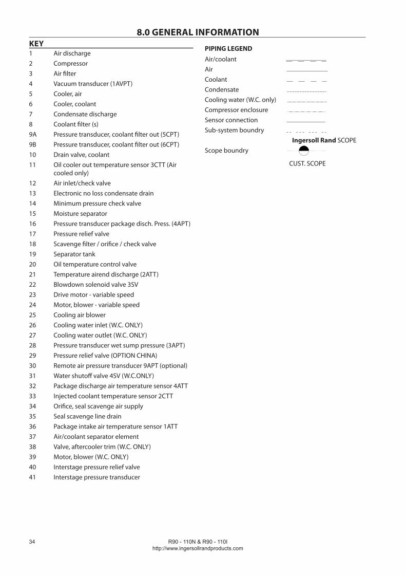
8.0 GENERAL INFORMATIONKEY1 Air discharge2 Compressor3 Air filter4 Vacuum transducer (1AVPT)5 Cooler, air6 Cooler, coolant7 Condensate discharge8 Coolant filter9A Pressure transducer, coolant filter in (5CPT)9B Pressure transducer, coolant filter out (6CPT)10 Drain valve, coolant11 Load / blowdown valve (1SV)12 Air inlet check valve13 Condensate drain valve (9SV)14 Minimum pressure check valve15 Moisture separator16 Pressure transducer package disch. Pressure (4APT)17 Pressure relief valve18 Scavenge filter / orifice / check valve 19 Separator tank20 Oil temperature control valve21 Temperature thermistor airend discharge (2ATT)22 Drive motor23 Motor, fan24 Cooling fan25 Cooling water inlet (w.C. Only)26 Cooling water outlet (w.C. Only)27 Pressure transducer wet sump pressure (3APT)28 Water shutoff valve (w.C. Only) (4SV)29 Ball valve (w.C. Only) trim valve30 Pressure relief valve (option china)31 Check valve (motor seal scavenge)32 Filter breather (motor seal scavenge)33 Remote air pressure transducer (10APT) (optional)34 Electronic drain trap-alternative to item 1335 Air/coolant separator element36 Package disch air temp sensor (4ATT)37 Temperature thermistor oil injection (2CTT)38 Modulation valve (5SV)
PIPING LEGEND
Air/coolantAirCoolantCondensateCooling water (W.C. only)Compressor enclosureSensor connectionSub-system boundry
Scope boundry
Ingersoll Rand SCOPE
CUST. SCOPE
R90 - 110N & R90 - 110Ihttp://www.ingersollrandproducts.com
��
8.0 GENERAL INFORMATION
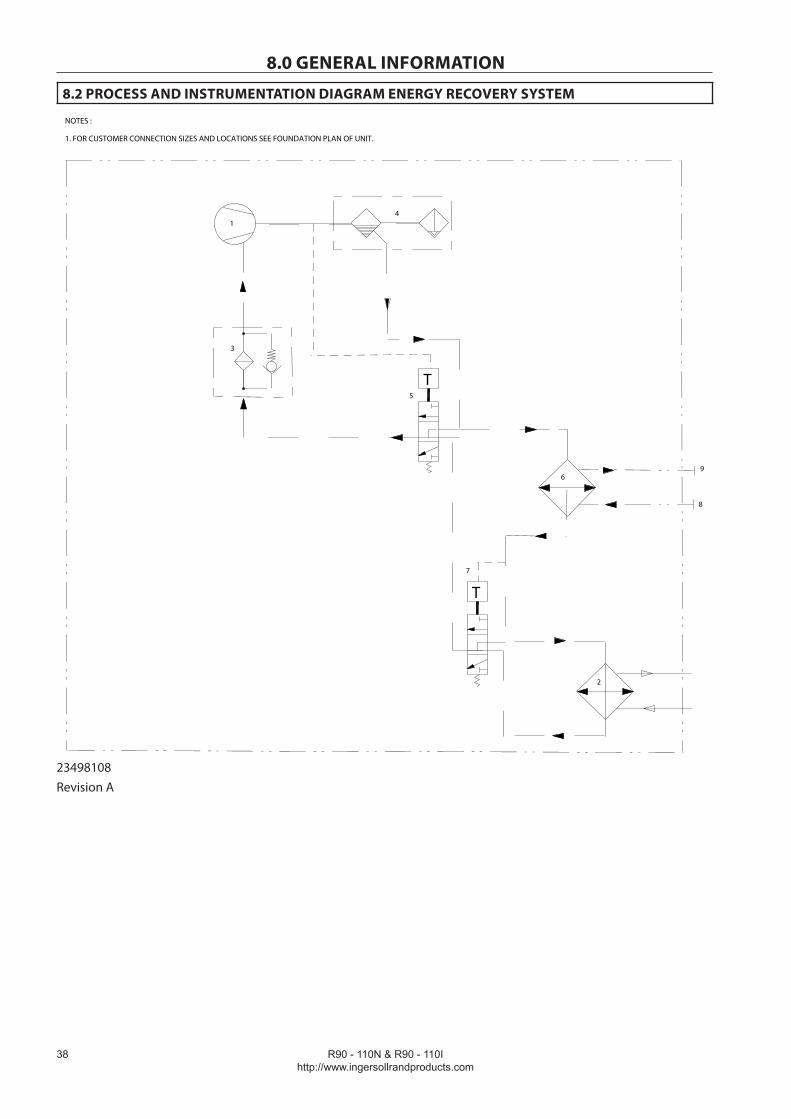
8.2 PROCESS AND INSTRUMENTATION DIAGRAM ENERGY RECOVERY SYSTEM
NOTES :
1. FOR CUSTOMER CONNECTION SIZES AND LOCATIONS SEE FOUNDATION PLAN OF UNIT.
1
2
4
7
T
5
T
69
8
3
23498108Revision A

R90 - 110N & R90 - 110Ihttp://www.ingersollrandproducts.com
�9
8.0 GENERAL INFORMATIONKEY1 Compressor2 Cooler, coolant (package)3 Coolant filter4 Separator tank (primary/secondary)5 Oil temperature control valve (package)6 Cooler, coolant (ERS)7 Oil temperature control valve (ERS)8 Cooling water inlet (ERS)
PIPING LEGEND
Air/coolantAirCoolantCondensateCooling water (W.C. only)Compressor enclosureSensor connection

R90 - 110N & R90 - 110Ihttp://www.ingersollrandproducts.com
�0
8.0 GENERAL INFORMATION
8.3 SCHEMATIC, ELECTRICAL WIRING (VSD)
FD
PE
12
18
27
55
60
02
01
DR
BLU
KM4-1
LR
MCB1 MCB2
DVF(x2)
BRNC
MCB3
MCB4
FM
123
K1-2283
285
206
207
294
295
GND
284
120
121
118
119
RFI
RFI
DVF
FD
DR
MM
YELBLKREDGREBROBLUVIO
GND
102127
102
150
1011
12
12 K2
PE
GND
2367
PX3
PX4
123
7654
98
10
PX2
K1-1
278
276279
+- P
WHTBLK
10APT
RED
WHT
2
3
4
5
6
7
KM1
KM4
K1
110
112
1
2
P10PX
1
PX6
MCB5
PSU
12V1
2 P1
3
4
1
2
P2
102
150
150
102
REDBLKBLKWHT
1
2
P8
ST
SL
113
BLK
REDBLK
RED
200
201
150
PORO
PE
1234567
244243
124
125
5L3
5L2
105
151
121120
ES-1
3SVP1
115V
TX1
TX2
TX3
TX4
TX5
TX6
+12Gnd
SG-NE P4-10
SG-NE P4-9
SG-NE P3-6
SG-NE P3-5
BLK
GRN
122
1278
K2-1128115V500VA
230V300VA
200V50VA
T1
EB
ES-3277
KM1 9 TX8117
12
P2
3
12
P73456
EXC
N/O
C
N/C
A+
B-
SC+
SC-
SD+
SD-
ES-2
FD 60
FD 55
FM
T1OV
PSU
SGN
CAB
3SV
MM
BP
CDV
DOOR
A1A2
A1A2
A1A2
8 TX7
294
295
150
4SV
4SV
PE
9
10
P4
AO+
AO1
1
2
3
7
6
5
4
9
8
10
11
18
17
16
15
14
13
12
RSP
RST
AW1
AW2
218
219
P3
DI1
Gnd
DI2
Gnd
DI3
Gnd
DI4
Gnd
DI5
Gnd
DI6
Gnd
DI7
Gnd
DI8
Gnd
DI9
Gnd
208
FD 01
FD 02
209
207
206
CDE
K1-3
SGNe
KM1-1280
150
12PX
7
ES-4296297
100
151
CDV
1.1 1.2 1.3
KL1
103
282
281
111
210
211
212
213
214
215
216
217
FM
I> I> I>
AIRCOOLED
WATER COOLED
207
206
FMP
AIRCOOLED
WATERCOOLED
10 GND
FMP
FU1, 2, 3
KM1
0VH6
H5
H4
H3
H2
H1
X1
X2
X3
X4
X5
X6
X7
380V
400V
415V
460V
480V
120V
110V
0V
200V
0V
230V
0V
123
7654
98
101112
P5
237238239240
242241
243
244245
REDBLKWHI
V+
Gnd
Sig1
V+
Gnd
Sig2
Gnd
Gnd
V+
V+
Sig3
Sig4
REDBLKWHIREDBLKWHI
131415
Gnd
V+
Sig5
246247248249250
REDBLKWHI
236
DR PX2-5REDBLKWHI
DR PX2-4
T
123
7654
8
P6
261262 WHI
BLK263264
266265
267
2CTT
2ATT
4ATT
3CTT
Sig1
Sig2
Sig3
Sig4
Gnd
Gnd
Gnd
Gnd
260 WHIBLK T
T
TWHIBLK
WHIBLK
910
Sig5
Gnd
131211
14274
Sig6
Sig7
Gnd
Gnd
1516
275 1ATTSig8
Gnd TWHIBLK
AO1
AI1+
AI1-
AI2
0V
+24V
DI1
DI2
EN
0V
COM
N/O
(NOTE 2)
SG-NE P5-8SG-NE P5-9
EMC
1AVPT
P3APT
P4APT
P5CPT
P6CPT
P161718
251
Gnd
V+
Sig5
192021
Gnd
V+
Sig6
252253254255256
REDBLKWHI
2APT
P(NOTE 3)
CFO300301302
KM4-1
303
304
MOTORRUNNINGCONTACT
104
1L31L21L1
1L31L21L1
3L33L23L1
4L34L24L1
L3L2L1
L3L2L1
1L3 1L2
WVU
1L31L21L1
3L33L23L1
WVU
WVU
L3L2L1
1L31L21L1
SHEET 1 OF 2
T1
301
KM4-2MCB9 T300 303
TH
304
305
HTR1 HTR2
NOTES:1. FACTORY SUPPLIED AS SHOWN BY CONNECTION TO OUTPUT OF CONTROL TRANSFORMER T1. WIRE TO TERMINAL NUMBERS 100 & 151.2. ALTERNATIVELY THE SUPPLY MAY BE TAKEN FROM AN INDEPENDENT SOURCE; IN THAT CASE, FACTORY SUPPLIED CONNECTION MUST BE DISCONNECTED.3. ENSURE PARALLEL CONNECTION OF HEATERS.
301
KM4-2MCB9 T300 303
TH
304
305
HTR1 HTR2
110/120V50/60Hz
220/230V50/60Hz
151
100 302
305
305
302
23382245Revision D

R90 - 110N & R90 - 110Ihttp://www.ingersollrandproducts.com
�1
8.0 GENERAL INFORMATIONKEYOV Zero voltage1ATT Package inlet temperature1AVPT Inlet vacuum pressure2APT Interstage air press (2S ONLY)2ATT Airend discharge temperature2CTT Injected coolent temperature3APT Wet sump pressure3CTT Coolant cooler out temp.3SV Blowdown valve4APT Package discharge pressure4ATT Package discharge temperature4SV Water shut off valve (W/C ONLY)5CPT Coolant filter in pressure6CPT Coolant filter out pressure10APT Remote pressureAW1 Auxiliary warning 1AW2 Auxiliary warning 2BP BackpanelCAB CabinetCDE Condensate drain errorCDV Condensate no loss drain valveCFO Common fault outputDR Drive, main motorDVF Drive ventilation fanEB Earthing barEMC EMC Filter boardES Emergency stop buttonEXC External communicationsFD Drive, blower motorFM Fan motorFMP Fan motor protectorFU- FusesGND GroundHTR- Panel space heaterK1 Run relayK2 Drive fault relayLR Line reactorKM1 Blower motor contactorKM4 Drive fan motor contactorKM5 Dryer motors contactorMCB Circuit breakersMM Main motorPE Protected earthPORO Power outage restart optionPSU Power suppply unit
PTC Motor winding thermistorRFI Radio frequency interfaceRSP Remote stopRST Remote startSGNE Controller, intellisysSL Serial linkST Service tool connectorT1 Control power transformerTH Thermostat ColorsBLK BlackBLU BlueBRO BrownGRE GreenPIN PinkRED RedSCR ScreenVIO VioletWHI WhiteYEL YellowWires
Numbers Function Wire color
1-99 100-199 100 - 199 200-299 300-399 GND
Power AC Control Grounded ACDC Control Auxiliary Ground
Black Red WhiteBlue Orange Green / Yellow
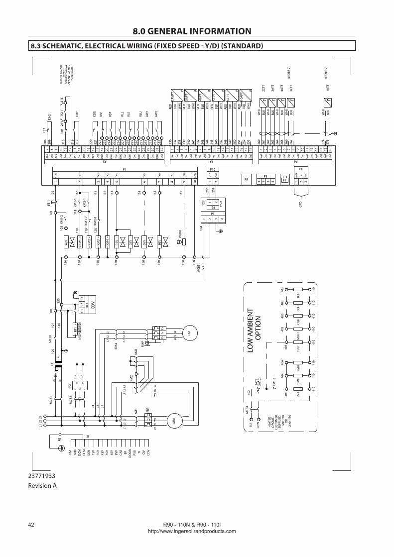
R90 - 110N & R90 - 110Ihttp://www.ingersollrandproducts.com
��
8.0 GENERAL INFORMATION8.3 SCHEMATIC, ELECTRICAL WIRING (FIXED SPEED - Y/D) (STANDARD)
MCB
1M
CB3
FM TI OV
PSU
DCM
SGN
CAB
3SV
DFMMM
BP
150
101
1 2 3 4 5 6 7
KM1
KM4
KM3
110
111
112
1 2
P10
MCB
5
PSU
12V
1 2P1
3 4
1 2
P2
150
150
150
150
101
1 2
P8
113
114
115 20
0
201
150
PORO
PE
100
3L3
3L1
104
L3 L2 L1
ES-1
1SV
5SV
9SV
P1
115V
TX1
TX2
TX3
TX4
TX5
TX6
115V
T1
EB
KM4
2L1
2L2
2L3
9TX
811
7
FMP
I>I>
I>
FM
U V
W
KM1
KM2
MM
KM3
L1 L
2 L3
L1 L
2 L
3L1
L2
L3
L1 L
2 L
3
MCB
2K2
L3 L1L2
214
215
11 14
150
KM2
4SV
KM1-
1
KM3-
1KM
3-2
Gnd+1
2
150
118
119
8TX
7
FR1
U1
V1
W1
W2
U2
V2
A1
A2
A1
A2
A1
A2
A1
A2
1SV
4SV
5SV
6SV
9SV
DO
OR
KM1-
2
102
7 98 10 11 18171615141312
ES-2 RL
U
RSP
RST
AW
1
AW
2
213
216
217
208
209
P3
FR1
FMP
214
K2-1
215
DI4
Gnd DI5
Gnd DI6
Gnd DI7
Gnd DI8
Gnd DI9
Gnd
RLE
REM
OVE
JUM
PER
WH
ENCO
RRES
PON
DIN
GO
PTIO
N H
AS
BEEN
PU
RCH
ASE
D
212019 2322 24 25 32313029282726
DI1
0
Gnd
DI1
1
Gnd
DI1
2
Gnd
DI1
3
Gnd
DI1
4
Gnd
DI1
5
Gnd
DI1
6
Gnd
RLL
KM2-
112
0
118
CDE
220
221
3 4
P9 P7
CDV
101
150
CDV
1.1
1.2
1.3
KL1
103
222
223
224
225
226
227
228
229
230
231
232
233
234
235
150
10G
ND
1 2
P2
3
CFO
N/O C N/C
1 2 3 7654 98 10 11 12
P5
237
238
239
240
242
241
243
244
245
RED
BLK
WH
I
V+ Gnd
Sig1 V+ Gnd
Sig2
Gnd
GndV+ V+Sig3
Sig4
RED
BLK
WH
IRE
DBL
KW
HI
13 14 15G
ndV+ Sig5
246
247
248
249
250
251
RED
BLK
WH
I
16 17 18G
ndV+ Sig6
252
253
RED
BLK
WH
I
236
RED
BLK
WH
I
1AVP
T
P3A
PT
P4A
PT
P5C
PT
P6C
PT
P10
APT
P
T
1 2 3 7654 8
P6
261
262
WH
IBL
K26
326
4
266
265
267
2CTT
2ATT
4ATT
3CTT
Sig1
Sig2
Sig3
Sig4
Gnd
Gnd
Gnd
Gnd
260
WH
IBL
KT T T
WH
IBL
K
WH
IBL
K
9 10Si
g5
Gnd
131211 14
1ATT
Sig6
Sig7
Gnd
Gnd
TW
HI
BLK
15 16Si
g8
Gnd
(NO
TE 2
)
274
275
FR1
A2
A1
(AS
NEE
DED
)
3SV
(NO
TE 2
)
1L1
L2/N
MCB
4
3ATS
(40
C)
KM1-
3
404
SSH
410
404
DM
H 410
404
FMH
410
403
1SVT
410
403
MSH
T
410
403
OSH
410
403
OSH
410
403
BLH
410
LOW
AM
BIEN
T O
PTIO
NH
EATE
RCI
RCU
IT,
CUST
OM
ERSU
PPLI
ED12
0/1/
60O
R24
0/1/
50
402
23771933Revision A

R90 - 110N & R90 - 110Ihttp://www.ingersollrandproducts.com
��
OV Zero voltage1ATT Package inlet temperature1AVPT Inlet vacuum pressure1SV Load valve1SVT 1SV heat trace2ATT Airend discharge temperature2CTT Injected coolent temperature3APT Wet sump pressure3ATS Ambient temp thermostat3CTT Coolant cooler out temp.4APT Package discharge pressure4ATT Aftercooler discharge temp4SV Water shut off valve (w/c only)5CPT Coolant filter in pressure5SV Modulation valve6CPT Coolant filter out pressure9SV Condensate drain valve10APT Remote pressureAW1 Auxiliary warning 1AW2 Auxiliary warning 2BLH Base level heaterBP BackpanelCAB CabinetCDE Condensate drain errorCDV Condensate drain valve (no loss)CFO Common fault outputDMH Drive motor heaterEB Earthing barES Emergency stop buttonFM Fan motorFMH Fan motor heaterFMP Fan motor protectorFR1 Main motor overloadFU- FusesK2 Phase monitor relayKM1 Main contactorKM2 Delta contactorKM3 Start contactorKM4 Fan motor contactorKM5 Dryer compressor contactorMCB Circuit breakersMM Main motorMSHT Moisture separator heat traceOSH Oil sump heaterPE Protected earthPORO Power outage restart optionPSU Power suppply unitPTC Motor Winding ThermistorRLE Remote load enableRLU Remote load / unloadRSP Remote stopRST Remote start
SG Controller, intellisysSS Solid state relaysSSH Starter space heaterT1 Control power transformerTH Thermostat ColorsBLK BlackBLU BlueBRO BrownGRE GreenPIN PinkRED RedVIO VioletWHI WhiteYEL Yellow
WIRE NUMBER DESIGNATION LEGEND
Numbers Function Wire color
1-99 100-199 100-199200-299 300-399 GND
Power AC Control Grounded ACDC ControlAuxiliary Ground
Black Red WhiteBlue Orange Green / Yellow
8.0 GENERAL INFORMATIONKEY
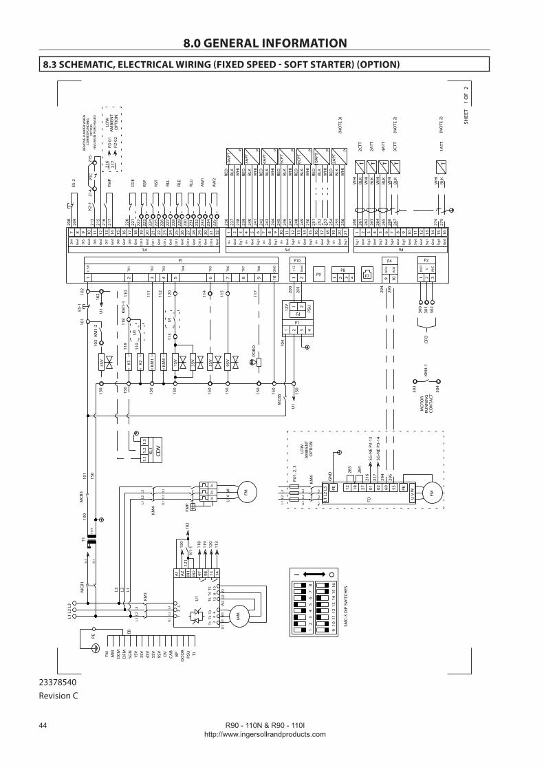
R90 - 110N & R90 - 110Ihttp://www.ingersollrandproducts.com
��
8.0 GENERAL INFORMATION
8.3 SCHEMATIC, ELECTRICAL WIRING (FIXED SPEED - SOFT STARTER) (OPTION)M
CB1
MC
B3
FM TIOV
PSU
DC
M
SGN
CA
B
3SV
DFMMM
BP
150
101
1 2 3 4 5 6 7
K1 KM4
KM1
110
111
112
1 2
P10
MC
B5
PSU
12V
1 2
P1
3 4
1 2
P2
150
150
150
150
101
120
114
115 20
0
201
150
PORO
PE
100
3L3
3L1
104
L3 L2 L1
ES-1
1SV
5SV
9SV
P1
115V
TX1
TX2
TX3
TX4
TX5
TX6
115V
T1
EB
KM4
2L1
2L2
2L3
9TX
811
7
FMP
I>I>
I>
FM
U V
W
L1 L
2 L3
L1 L
2 L
3
L1 L
2 L
3
3SV
150
K24SV
KM1-
1
Gn
d
+12
150
118
119
8TX
7
A1
A2
A1
A2
A1
A2
A1
A2
1SV
4SV
5SV
9SV
DO
OR
KM1-
2
118
KM1
MM
U1
V1
W1
U1
A1
A2
IN1
139897IN2
142
4
61
3 5
150
K1-1
102
118
119
120
113
121
1L1
1L2
1L3
U1
150
U1
102
U1
9798
U1
1314
1 2
P8
3 4
P9 P7
CD
V
1.1
1.2
1.3
KL1
103
W2
U2
V2
12
8 1
0T1
T2
T3
T6 T
4 T
5
113
7 98 10 11 18171615141312
ES-2
RLU
RSP
RST
AW
1
AW
2
213
216
217
208
209
P3
FMP
K2-1
DI4
Gn
d
DI5
Gn
d
DI6
Gn
d
DI7
Gn
d
DI8
Gn
d
DI9
Gn
d
RLE
212019 2322 24 25 32313029282726
DI1
0
Gn
d
DI1
1
Gn
d
DI1
2
Gn
d
DI1
3
Gn
d
DI1
4
Gn
d
DI1
5
Gn
d
DI1
6
Gn
d
RLL
CD
E22
022
122
222
322
422
522
622
722
822
923
023
123
223
323
423
5
1 2 3 7654 98 10 11 12
P5
237
238
239
240
242
241
243
244
245
RED
BLK
WH
I
V+
Gn
d
Sig
1
V+
Gn
d
Sig
2
Gn
d
Gn
d
V+
V+
Sig
3
Sig
4
RED
BLK
WH
IRE
DBL
KW
HI
13 14 15G
nd
V+
Sig
5
246
247
248
249
250
251
RED
BLK
WH
I
16 17 18G
nd
V+
Sig
6
252
253
RED
BLK
WH
I
236
RED
BLK
WH
I
1AV
PT
P
3APT
P
4APT
P
5CPT
P
6CPT
P
10A
PT
P
T
1 2 3 7654 8
P6
261
262
WH
IBL
K26
326
4
266
265
267
2CTT
2ATT
4ATT
3CTT
Sig
1
Sig
2
Sig
3
Sig
4
Gn
d
Gn
d
Gn
d
Gn
d
260
WH
IBL
KT T T
WH
IBL
K
WH
IBL
K
9 10Si
g5
Gn
d
131211 14
1ATT
Sig
6
Sig
7
Gn
d
Gn
d
TW
HI
BLK
15 16Si
g8
Gn
d
(NO
TE 2
)
274
275
1 2
P2
3
N/O C N/C
10G
ND
150
(NO
TE 2
)
FD
U V
W
L1 L
2 L3 PE 12 18 27 55600201
FM
283
216
217
294
295
GN
D 284
4L1
4L2
4L3
SG-N
E P3
-14
SG-N
E P3
-13
KM4
3L1
3L2
3L3 PE
LOW
AM
BIEN
TO
PTIO
N
FU1,
2, 3
9 10
AO
+
AO
1
P4
294
295
L1 L
2 L
3
FD 0
1FD
02
217
216
LOW
AM
BIEN
TO
PTIO
N
12
34
56
78
910
1112
1314
1516
I O
SMC
-3 D
IP S
WIT
CH
ES
215
CFO
300
301
302
KM4-
1
303
304
MO
TOR
RUN
NIN
GC
ON
TAC
T
214
REM
OV
E JU
MPE
R W
HEN
C
ORR
ESPO
ND
ING
OPT
ION
HA
S BE
EN P
URC
HA
SED
215
PTC
102
254
19 20 21G
nd
V+
Sig
7
255
256
RED
BLK
WH
I
2APT
P(N
OTE
3)
SHEE
T1
OF
2
23378540Revision C
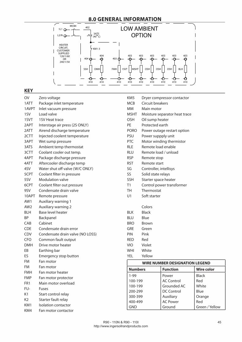
R90 - 110N & R90 - 110Ihttp://www.ingersollrandproducts.com
��
8.0 GENERAL INFORMATION
OV Zero voltage1ATT Package inlet temperature1AVPT Inlet vacuum pressure1SV Load valve1SVT 1SV Heat trace2APT Interstage air press (2S ONLY)2ATT Airend discharge temperature2CTT Injected coolent temperature3APT Wet sump pressure3ATS Ambient temp thermostat3CTT Coolant cooler out temp.4APT Package discharge pressure4ATT Aftercooler discharge temp4SV Water shut off valve (W/C ONLY)5CPT Coolant filter in pressure5SV Modulation valve6CPT Coolant filter out pressure9SV Condensate drain valve10APT Remote pressureAW1 Auxiliary warning 1AW2 Auxiliary warning 2BLH Base level heaterBP BackpanelCAB CabinetCDE Condensate drain errorCDV Condensate drain valve (NO LOSS)CFO Common fault outputDMH Drive motor heaterEB Earthing barES Emergency stop buttonFM Fan motorFM Fan motorFMH Fan motor heaterFMP Fan motor protectorFR1 Main motor overloadFU- FusesK1 Start control relayK2 Starter fault relayKM1 Isolation contactorKM4 Fan motor contactor
KM5 Dryer compressor contactorMCB Circuit breakersMM Main motorMSHT Moisture separator heat traceOSH Oil sump heaterPE Protected earthPORO Power outage restart optionPSU Power suppply unitPTC Motor winding thermistorRLE Remote load enableRLU Remote load / unloadRSP Remote stopRST Remote startSG Controller, intellisysSS Solid state relaysSSH Starter space heaterT1 Control power transformerTH ThermostatU1 Soft starter
ColorsBLK BlackBLU BlueBRO BrownGRE GreenPIN PinkRED RedVIO VioletWHI WhiteYEL Yellow
WIRE NUMBER DESIGNATION LEGEND
Numbers Function Wire color
1-99 100-199 100-199200-299 300-399400-499 GND
Power AC Control Grounded ACDC ControlAuxiliary AC PowerGround
Black Red WhiteBlue Orange RedGreen / Yellow
1L1
L2/N
MCB4
3ATS(40 C)
KM1-3
404
SSH
410
404
DMH
410
403
FMH
410
403
1SVT
410
403
MSHT
410
403
OSH
410
403
OSH
410
403
OSH
410
LOW AMBIENT OPTION
HEATERCIRCUIT,
CUSTOMERSUPPLIED
120/1/60OR
240/1/50
402
403
BLH
410
KEY
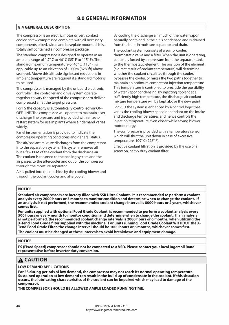
R90 - 110N & R90 - 110Ihttp://www.ingersollrandproducts.com
��
8.0 GENERAL INFORMATION
8.4 GENERAL DESCRIPTION
The compressor is an electric motor driven, contact cooled screw compressor, complete with all necessary components piped, wired and baseplate mounted. It is a totally self contained air compressor package.The standard compressor is designed to operate in an ambient range of 1.7° C to 46° C (35° F to 115° F). The standard maximum temperature of 46° C (115° F) is applicable up to an elevation of 1000m (3280ft) above sea level. Above this altitude significant reductions in ambient temperature are required if a standard motor is to be used.The compressor is managed by the onboard electronic controller. The controller and drive system operate together to vary the speed of the compressor to deliver compressed air at the target pressure.For FS the capacity is automatically controlled via ‘ON-OFF LINE’. The compressor will operate to maintain a set discharge line pressure and is provided with an auto restart system for use in plants where air demand varies widely.Panel instrumentation is provided to indicate the compressor operating conditions and general status.The air/coolant mixture discharges from the compressor into the separation system. This system removes all but a few PPM of the coolant from the discharge air. The coolant is returned to the cooling system and the air passes to the aftercooler and out of the compressor through the moisture separator.Air is pulled into the machine by the cooling blower and through the coolant cooler and aftercooler.
By cooling the discharge air, much of the water vapor naturally contained in the air is condensed and is drained from the built-in moisture separator and drain.The coolant system consists of a sump, cooler, thermostatic valve and a filter. When the unit is operating, coolant is forced by air pressure from the separator tank to the thermostatic element. The position of the element (a direct result of coolant temperature) will determine whether the coolant circulates through the cooler, bypasses the cooler, or mixes the two paths together to maintain an optimum compressor injection temperature. This temperature is controlled to preclude the possibility of water vapor condensing. By injecting coolant at a sufficiently high temperature, the discharge air coolant mixture temperature will be kept above the dew point. For VSD the system is enhanced by a control logic that varies the cooling blower speed dependant on the intake and discharge temperatures and hence controls the injection temperature even closer while saving blower motor energy.The compressor is provided with a temperature sensor which will shut the unit down in case of excessive temperature, 109° C (228° F).Effective coolant filtration is provided by the use of a screw on, heavy duty coolant filter.
NOTICE
Standard air compressors are factory filled with SSR Ultra Coolant. It is recommended to perform a coolant analysis every 2000 hours or 3 months to monitor condition and determine when to change the coolant. If an analysis is not performed, the recommended coolant change interval is 8000 hours or 2 years, whichever comes first.For units supplied with optional Food Grade Coolant, is recommended to perform a coolant analysis every 500 hours or every month to monitor condition and determine when to change the coolant. If an analysis is not performed, the recommended coolant change intervals is 2000 hours or 6 months, when utilizing the X-Tend Food Grade filter supplied with the machine. For units running Food Grade Coolant WITHOUT the X-Tend Food Grade Filter, the change interval should be 1000 hours or 6 months, whichever comes first.The coolant must be changed at these intervals to avoid breakdown and equipment damage.
NOTICE
FS (Fixed Speed) compressor should not be connected to a VSD. Please contact your local Ingersoll Rand representative before inverter duty conversion.
CAUTIONLOW DEMAND APPLICATIONSFor FS during periods of low demand, the compressor may not reach its normal operating temperature. Sustained operation at low demand can result in the build up of condensate in the coolant. If this situation occurs, the lubricating characteristics of the coolant can be impaired which may lead to damage of the compressor.THE COMPRESSOR SHOULD BE ALLOWED AMPLE LOADED RUNNING TIME.

R90 - 110N & R90 - 110Ihttp://www.ingersollrandproducts.com
��
9.0 OPERATING INSTRUCTIONS9.1 OPERATING INSTRUCTIONS FOR VSD
9.1.1 BASIC OPERATION
WARNING
Ensure that all protective covers/guards are in place before attempting to start the machine.
WARNING
The compressor can operate in a pressurized shutdown mode. If the compressor stops automatically, the airend, separator tank and oil system can contain high pressure air. This can be relieved by pressing the emergency stop button and can be verified by unscrewing the coolant fill plug which has a vent hole through which any residual pressure will be vented. Downstream of the separator tank may still contain system pressure which must also be vented.
NOTICE
The language and units of measure displayed on the Intellisys controller will be pre-set before leaving the factory. If these are required to be changed, contact your local Ingersoll Rand Service Department, Distributor or Air Center.
Prior to starting
Refer to diagram T5716 above.
Check that the coolant level is at least visible in the center of the sight glass, add coolant if necessary. Refer to maintenance procedures for setting correct level.
Ensure that the discharge air isolation valve is open. Switch on the main electrical isolation switch. The control panel will illuminate, indicating that the line and control voltages are available.
The contrast of the display may be adjusted by turning the small screw which is on the right hand side of the controller when accessed through the starter cabinet door.
Initial check sequence
The controller will perform an initial check sequence if the compressor (1) receives initial power to the controller or (2) has experienced an trip reset. While the initial check sequence occurs, the controller will display a “Checking Machine” message.
During the initial check sequence, the controller will check the control system for proper operation. During this time, if any items are found inoperative a trip will occur and the unit will not start.
After completion of the initial check sequence, the controller will then display “READY TO START’. This process should be completed within 10 seconds.

R90 - 110N & R90 - 110I http://www.ingersollrandproducts.com
��
9.0 OPERATING INSTRUCTIONSStart sequence
The compressor will initially start by the operator pressing the local start button or receiving a remote start command. The compressor will start loaded and will ramp up the motor speed to its minimum speed. Once the minimum speed has been achieved, the compressor will begin to control pressure by using its speed regulation. When the system pressure reaches the target pressure, the compressor will start to slow. If the system pressure rises to the immediate stop pressure setpoint the compressor will stop. If the system pressure rises to the auto stop setpoint and the compressor is at minimum speed, if the blowdown mode is set to off, the compressor will stop. However if the blowdown mode is set to on, the compressor will open the blowdown valve for up to 10 seconds or until the pressure in the separator tank falls to 2.4 Bar (35 psi) before stopping. The compressor will restart once the system pressure falls below the target pressure.
Stop sequence
The compressor can be stopped by a local or remote stop, a shutdown due to a trip or an emergency stop. All of the above conditions will cause the compressor to stop immediately, except the local or remote stop. A local or remote stop will open the blowdown valve and the compressor will run for up to 10 seconds or until the pressure in the separator tank falls to 35 psi before stopping. The compressor will stop if the system pressure reaches the automatic stop or immediate stop pressure setpoints. However, if the compressor stops for this reason, it will automatically restart when the system pressure falls below the target pressure.
Important: Depress the emergency stop button when the compressor must be stopped immediately.
Warm Up Mode:
A warm up cycle occurs when the compressor’s airend discharge temperature doesn’t reach the required warm up temperature (82°C/180°F) for two consecutive operational cycles. On a warm up cycle, instead of stopping, the compressor will continue to run with the blowdown valve open. The compressor will run in a fixed speed mode, at minimum speed. The blower will operate at minimum speed. The compressor will run like this for approximately 5 minutes. During a warm up cycle, the controller will display the message “Warm Up Mode”. If the pressure falls during this time period, the compressor will return to normal operation.
Blower control
The blower speed varies in some conditions to assist in controlling the aftercooler approach temperature and the coolant injection temperature. The blower motor has its own variable speed drive and will ramp up and down as the compressor starts and stops.
Stopping the machine in an emergency
If the machine has to be stopped in an emergency DEPRESS THE EMERGENCY STOP BUTTON LOCATED UNDERNEATH THE INSTRUMENT PANEL.
This will over-ride the normal unload/stop button and will immediately stop the machine.
Restarting after an emergency
If the unit has been switched off because of a machine malfunction, identify and correct the fault before attempting to restart.
If the unit has been switched off for reasons of safety, ensure that the machine can be operated safely before restarting.
Refer to the PRIOR TO STARTING and START SEQUENCE instructions earlier in this section before restarting the machine.

R90 - 110N & R90 - 110Ihttp://www.ingersollrandproducts.com
�9
9.0 OPERATING INSTRUCTIONS
9.1.2 INTELLISYS CONTROLS (VSD)
1. Emergency stop
Pressing this switch stops the compressor immediately. The blowdown valve will open to vent pressure in the separator tank to atmosphere. Note the system downstream of the separator tank may still contain pressure. The compressors can not be restarted until the switch is manually reset. Turn the switch knob clockwise and press the reset button twice to reset.
On reset the controller will display a message, indicating that the compressor is ready to start.
2. Start
Pressing this button will activate the start sequence.
3. Stop
Pressing this button will activate the stop sequence.
4. F1
Not used.
5. F2
Not used.
6. Arrows
These up and down buttons have multiple functions relating to the right half of the display screen. When lists are presented, the buttons are used to move up or down through the items on the list. The small arrow(s) displayed in the upper right hand corner of the display screen indicate when you can move up (designated by arrow head pointing up) and/or down (designated by arrow head pointing down) through the list.
When the value of a specific machine operating parameter is highlighted on the display screen for the purpose of changing that value, the buttons are used to change the value itself.
7. Display buttons
The functions of the three buttons below the display screen change and are defined by the words immediately above them in the bottom line of the screen. Each function, such as MAIN MENU, STATUS, etc., is described in appropriate sections in this manual.
F2F1
1
4 5 32
6
7
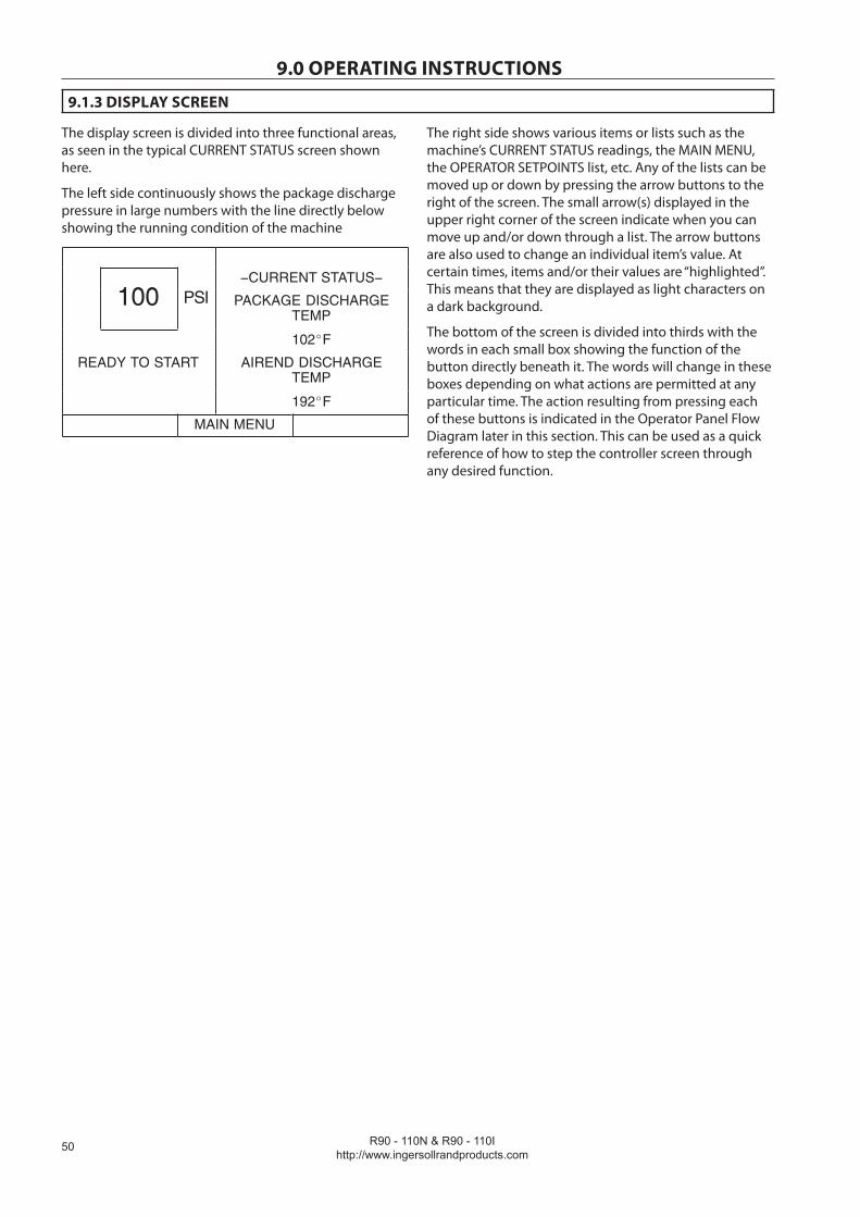
R90 - 110N & R90 - 110I http://www.ingersollrandproducts.com
�0
9.0 OPERATING INSTRUCTIONS
9.1.3 DISPLAY SCREEN
The display screen is divided into three functional areas, as seen in the typical CURRENT STATUS screen shown here.
The left side continuously shows the package discharge pressure in large numbers with the line directly below showing the running condition of the machine
100−CURRENT STATUS−
100 PSI PACKAGE DISCHARGETEMP
102 F
READY TO START AIREND DISCHARGETEMP
192 F
MAIN MENU
The right side shows various items or lists such as the machine’s CURRENT STATUS readings, the MAIN MENU, the OPERATOR SETPOINTS list, etc. Any of the lists can be moved up or down by pressing the arrow buttons to the right of the screen. The small arrow(s) displayed in the upper right corner of the screen indicate when you can move up and/or down through a list. The arrow buttons are also used to change an individual item’s value. At certain times, items and/or their values are “highlighted”. This means that they are displayed as light characters on a dark background.
The bottom of the screen is divided into thirds with the words in each small box showing the function of the button directly beneath it. The words will change in these boxes depending on what actions are permitted at any particular time. The action resulting from pressing each of these buttons is indicated in the Operator Panel Flow Diagram later in this section. This can be used as a quick reference of how to step the controller screen through any desired function.

R90 - 110N & R90 - 110Ihttp://www.ingersollrandproducts.com
�1
9.0 OPERATING INSTRUCTIONS
9.1.4 CURRENT STATUS SCREEN
The CURRENT STATUS screen is considered to be the “normal” display that the controller shows.
The following items and their present values can be displayed on the right side of the screen by pressing the up and down arrow buttons
The controller automatically returns the display to this CURRENT STATUS screen from other screens if no buttons are pressed within 30 seconds.
Use the UP and DOWN arrows to move between selections.
CURRENT STATUS items
1 % Energy Saving
2 % Capacity
3 Package kW
4 Package Discharge Temperature
5 Airend Discharge Temperature
6 Injected Coolant Temperature
7 Sump Pressure
8 Separator Pressure Drop
9 Coolant Filter Pressure Drop
10 Inlet Vacuum
11 Inlet Filter
12 Total Hours
13 Motor Speed
14 Remote Pressure (optional)
15 Time and Date
16 Program Name
17 Version of Drive Software
When the CURRENT STATUS screen is displayed, pressing the ENERGY STATUS button will toggle the display to the ENERGY STATUS screen. Likewise, when the ENERGY STATUS screen is displayed, pressing the STATUS button will toggle the display to the CURRENT STATUS screen.
The ENERGY STATUS screen displays the following items.
ENERGY STATUS Items
1 Average Package kW-hr
2 Average % Capacity
3 Average Capacity
4 Energy Cost
5 Energy Savings
6 Lifetime Energy Savings
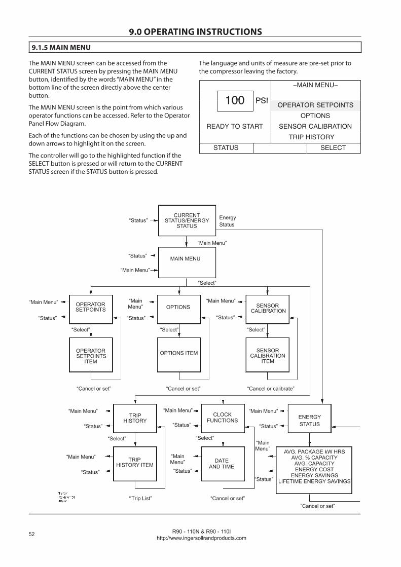
R90 - 110N & R90 - 110I http://www.ingersollrandproducts.com
��
9.0 OPERATING INSTRUCTIONS
9.1.5 MAIN MENU
The MAIN MENU screen can be accessed from the CURRENT STATUS screen by pressing the MAIN MENU button, identified by the words “MAIN MENU” in the bottom line of the screen directly above the center button.
The MAIN MENU screen is the point from which various operator functions can be accessed. Refer to the Operator Panel Flow Diagram.
Each of the functions can be chosen by using the up and down arrows to highlight it on the screen.
The controller will go to the highlighted function if the SELECT button is pressed or will return to the CURRENT STATUS screen if the STATUS button is pressed.
The language and units of measure are pre-set prior to the compressor leaving the factory.
−MAIN MENU−
100 PSI100 PSIOPERATOR SETPOINTS
OPTIONS
READY TO START SENSOR CALIBRATION
TRIP HISTORY
STATUS SELECT
OPERATORSETPOINTS
OPERATOR SETPOINTS
ITEM
MAIN MENU
CURRENTSTATUS/ENERGY
STATUS
OPTIONS
OPTIONS ITEM
SENSOR CALIBRATION
SENSORCALIBRATION
ITEM
TRIPHISTORY
TRIPHISTORY ITEM
CLOCKFUNCTIONS
DATEAND TIME
“Status”
“Status”
“Main Menu”
“Main Menu”
“Select”
”sutatS“”sutatS“ “Status”
“Status”“Status”
“Main Menu” “MainMenu”
“Main Menu”
“Main Menu” “Main Menu”
“Status”
“MainMenu”
“Status”
“Main Menu”
”etarbilac ro lecnaC“”tes ro lecnaC“”tes ro lecnaC“
”tes ro lecnaC“”tsLi Trip“
”tceleS“”tceleS“”tceleS“
“Select” “Select”
“Status”
“Main Menu”
“Cancel or set”
ENERGYSTATUS
AVG. PACKAGE kW HRSAVG. % CAPACITY
AVG. CAPACITYENERGY COST
ENERGY SAVINGSLIFETIME ENERGY SAVINGS“Status”
“MainMenu”
EnergyStatus
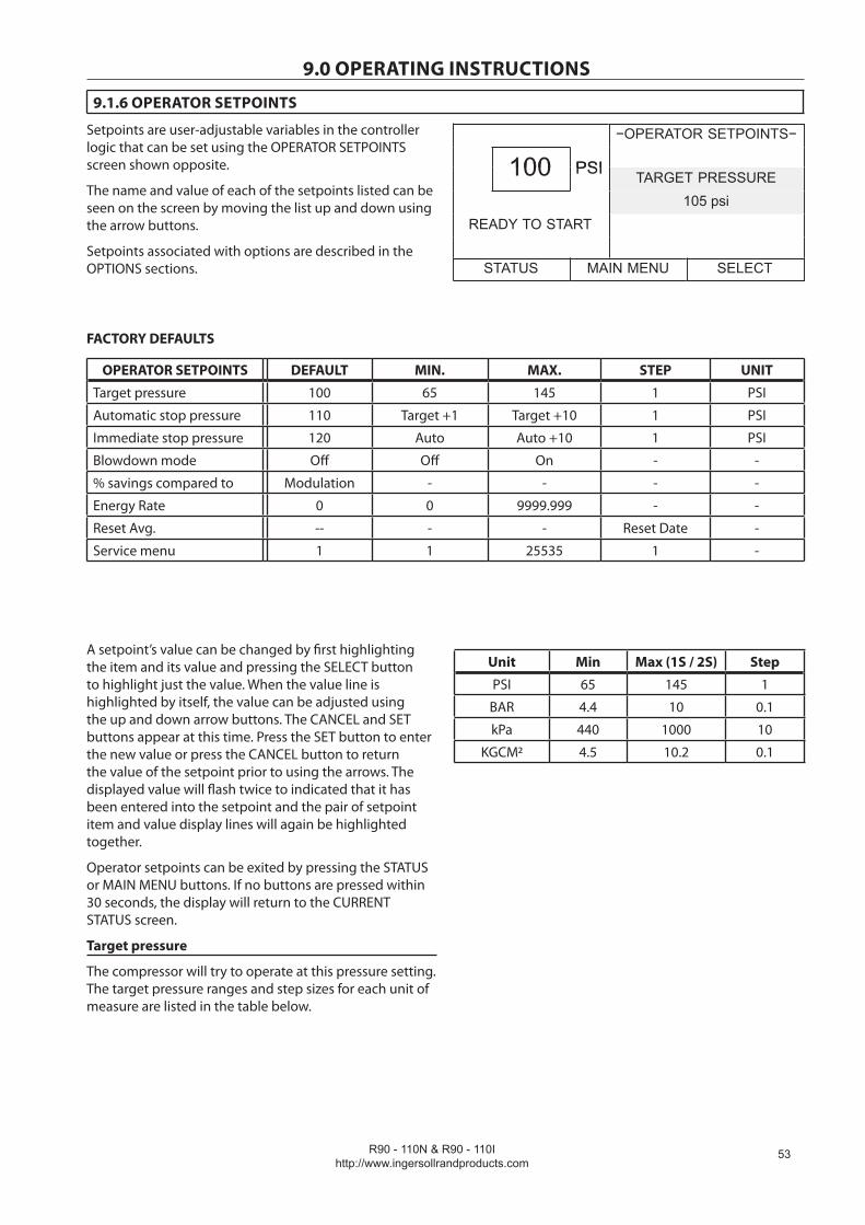
R90 - 110N & R90 - 110Ihttp://www.ingersollrandproducts.com
��
9.0 OPERATING INSTRUCTIONS
9.1.6 OPERATOR SETPOINTS
Setpoints are user-adjustable variables in the controller logic that can be set using the OPERATOR SETPOINTS screen shown opposite.
The name and value of each of the setpoints listed can be seen on the screen by moving the list up and down using the arrow buttons.
Setpoints associated with options are described in the OPTIONS sections.
−OPERATOR SETPOINTS−
100 PSI100 PSI TARGET PRESSURE105 psi
READY TO START
STATUS MAIN MENU SELECT
FACTORY DEFAULTS
OPERATOR SETPOINTS DEFAULT MIN. MAX. STEP UNIT
Target pressure 100 65 145 1 PSI
Automatic stop pressure 110 Target +1 Target +10 1 PSI
Immediate stop pressure 120 Auto Auto +10 1 PSI
Blowdown mode Off Off On - -
% savings compared to Modulation - - - -
Energy Rate 0 0 9999.999 - -
Reset Avg. -- - - Reset Date -
Service menu 1 1 25535 1 -
A setpoint’s value can be changed by first highlighting the item and its value and pressing the SELECT button to highlight just the value. When the value line is highlighted by itself, the value can be adjusted using the up and down arrow buttons. The CANCEL and SET buttons appear at this time. Press the SET button to enter the new value or press the CANCEL button to return the value of the setpoint prior to using the arrows. The displayed value will flash twice to indicated that it has been entered into the setpoint and the pair of setpoint item and value display lines will again be highlighted together.
Operator setpoints can be exited by pressing the STATUS or MAIN MENU buttons. If no buttons are pressed within 30 seconds, the display will return to the CURRENT STATUS screen.
Target pressure
The compressor will try to operate at this pressure setting. The target pressure ranges and step sizes for each unit of measure are listed in the table below.
Unit Min Max (1S / 2S) Step
PSI 65 145 1
BAR 4.4 10 0.1
kPa 440 1000 10
KGCM2 4.5 10.2 0.1

R90 - 110N & R90 - 110I http://www.ingersollrandproducts.com
��
9.0 OPERATING INSTRUCTIONSAutomatic stop pressure
The compressor will stop once the system pressure rises to this pressure and the compressor is operating at the minimum speed. The range for this setpoint will be the target pressure+1 to target pressure+10 psi.
Immediate stop pressure
The compressor will stop if the system pressure rises to this pressure. The range for this setpoint will be the automatic stop pressure to automatic stop pressure+10 psi.
Blowdown Mode
2 stage compressors will always blowdown when signaled to stop.
If this mode is selected to ON the compressor will open the blowdown valve anytime that it stops. This will vent pressure from the airend and the separator tank. If this mode is selected to OFF the blowdown valve will remain closed when the compressor stops due to an automatic stop. Blowdown mode is set on at all times for 2 stage models. Blowdown mode will be shown as ”Not Installed” at the controller display.
% savings compared to
This setpoint is to determine what VSD’s percent of savings is compared to. The modes of operation for comparing VSD to are modulation, online/offline, and geometry. The percent savings value is displayed by the status message, % energy savings
Energy Rate
The energy cost and the energy savings items on the ENERGY STATUS screen will use this value for their calculations. It is intended to be a monetary value representing the user’s power cost per kilowatt hour.
Reset Averaging
When this setpoint is selected and the SET button is pressed, the items on the ENERGY STATUS screen will be reset, and the date the reset occurred will be displayed in this setpoint. This selects the beginning of the time period over which the ENERGY STATUS information will be calculated. Note that the “Lifetime Energy Savings” item will not be reset.
Service Menu
For use by Ingersoll Rand personnel only.
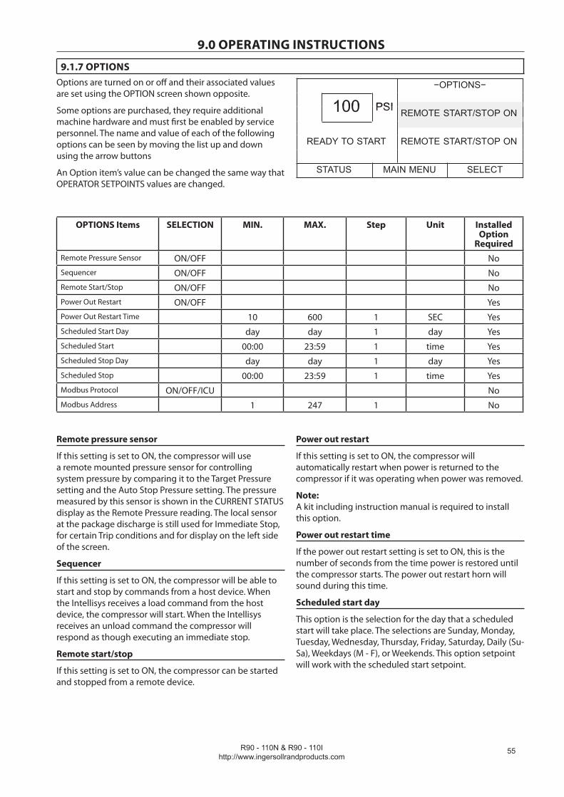
R90 - 110N & R90 - 110Ihttp://www.ingersollrandproducts.com
��
9.0 OPERATING INSTRUCTIONS
9.1.7 OPTIONSOptions are turned on or off and their associated values are set using the OPTION screen shown opposite.
Some options are purchased, they require additional machine hardware and must first be enabled by service personnel. The name and value of each of the following options can be seen by moving the list up and down using the arrow buttons
An Option item’s value can be changed the same way that OPERATOR SETPOINTS values are changed.
−OPTIONS−
100 PSI100 PSI REMOTE START/STOP ON
READY TO START REMOTE START/STOP ON
STATUS MAIN MENU SELECT
OPTIONS Items SELECTION MIN. MAX. Step Unit Installed Option
Required Remote Pressure Sensor ON/OFF No Sequencer ON/OFF No Remote Start/Stop ON/OFF No Power Out Restart ON/OFF Yes Power Out Restart Time 10 600 1 SEC Yes Scheduled Start Day day day 1 day Yes Scheduled Start 00:00 23:59 1 time Yes Scheduled Stop Day day day 1 day Yes Scheduled Stop 00:00 23:59 1 time Yes Modbus Protocol ON/OFF/ICU No Modbus Address 1 247 1 No
Remote pressure sensor
If this setting is set to ON, the compressor will use a remote mounted pressure sensor for controlling system pressure by comparing it to the Target Pressure setting and the Auto Stop Pressure setting. The pressure measured by this sensor is shown in the CURRENT STATUS display as the Remote Pressure reading. The local sensor at the package discharge is still used for Immediate Stop, for certain Trip conditions and for display on the left side of the screen.
Sequencer
If this setting is set to ON, the compressor will be able to start and stop by commands from a host device. When the Intellisys receives a load command from the host device, the compressor will start. When the Intellisys receives an unload command the compressor will respond as though executing an immediate stop.
Remote start/stop
If this setting is set to ON, the compressor can be started and stopped from a remote device.
Power out restart
If this setting is set to ON, the compressor will automatically restart when power is returned to the compressor if it was operating when power was removed.
Note: A kit including instruction manual is required to install this option.
Power out restart time
If the power out restart setting is set to ON, this is the number of seconds from the time power is restored until the compressor starts. The power out restart horn will sound during this time.
Scheduled start day
This option is the selection for the day that a scheduled start will take place. The selections are Sunday, Monday, Tuesday, Wednesday, Thursday, Friday, Saturday, Daily (Su- Sa), Weekdays (M - F), or Weekends. This option setpoint will work with the scheduled start setpoint.

R90 - 110N & R90 - 110I http://www.ingersollrandproducts.com
��
9.0 OPERATING INSTRUCTIONSScheduled start
This option will cause the unit to start on the scheduled start day , at the time stored in this setpoint. To disable this option, set the value of scheduled start equal to the value of scheduled stop.
Scheduled stop day
This option is the selection for the day that a scheduled stop will take place. The selections are Sunday, Monday, Tuesday, Wednesday, Thursday, Friday, Saturday, Daily (Su - Sa), Weekdays (M - F), or Weekends. This option setpoint will work with the scheduled stop setpoint.
Scheduled stop
This option will cause the unit to stop on the scheduled stop day, at the time stored in this setpoint. To disable this option, set the value of scheduled stop equal to the value of scheduled start.
9.1.8 SENSOR CALIBRATION
Pressure sensor calibration is done through the SENSOR CALIBRATION screen. Sensor calibration can only take place when the machine is stopped. Calibration needs to be done only after a sensor has been replaced or the Intellisys controller has been replaced.
−SENSOR CALIBRATION−
100 PSI100 PSI SENSOR 4APTCALIBRATE
READY TO START SENSOR 3APTCALIBRATE
STATUS MAIN MENU SELECT
Each of the sensors listed below can be chosen by using the up and down arrow buttons to highlight it on the screen.
SENSOR CALIBRATION Items Sensor 1VAPT (Inlet Vacuum) Sensor 4APT (Package Discharge) Sensor 3APT (Wet Side Sump) Sensor 5CPT (Coolant Filter In) Sensor 6CPT (Coolant Filter Out) Sensor 2APT (Interstage) (On 2 stage compressors only) Sensor 7APT (Aftercooler-dryer units only)
Select the highlighted sensor by pressing the SELECT button. Press the CALIBRATE button to start the automatic calibration procedure, or press the CANCEL button to not calibrate it and return to the sensor list.
The calibration screen can be exited by pressing either the STATUS or MAIN MENU buttons. If no buttons are pressed within 30 seconds, the display will return to the CURRENT STATUS screen.

R90 - 110N & R90 - 110Ihttp://www.ingersollrandproducts.com
��
9.0 OPERATING INSTRUCTIONS
9.1.9 TRIP HISTORY
Trip History displays each of the Trip messages for the last 15 Trips experienced by the machine. It also gives access to displaying the machine operating conditions that existed at the time of each Trip. The first one shown, “Trip History 1”, was the most recent Trip to occur. Note that multiple, consecutive EMERGENCY STOP Trips are not recorded as separate Trips, only the first one will be shown.
−TRIP HISTORY−
100 PSI100 PSI TRIP HISTORY 1BLOWER MOTOR
OVERLOAD
READY TO START TRIP HISTORY 2HIGH AIREND DISCH
TEMP
STATUS MAIN MENU SELECT
Each of the last 15 Trip messages can be seen by moving the Trip History list up and down using the arrow buttons. Pressing the SELECT button when one of the Trips is highlighted will display the list of machine values that existed at the time that particular Trip occurred.
The name and value of each of the items can be seen by moving the list up and down using the arrow buttons. Pressing the TRIP HIST. button will return the display to the TRIP HISTORY screen.
Trip histories can be exited by pressing either the STATUS or MAIN MENU buttons. If no buttons are pressed within 30 seconds, the display will return to the CURRENT STATUS screen.
9.1.10 CLOCK FUNCTIONS
−CLOCK FUNCTIONS−
100 PSITime 01:15
DateREADY TO START
DateJan 01, 00Jan 01, 00
STATUS MAIN MENU SELECT
The date and time for the real time clock is set through the CLOCK FUNCTIONS screen. Use the up and down arrows to highlight either TIME or DATE. Select the highlighted setting by pressing SELECT.
If TIME is selected, first the hours will be highlighted. Adjust the hours (00-23 hour clock) by using the up and down arrows. Once the correct time is in the display, press SET to highlight the minutes. Adjust the minutes (00-59) and then press SET to complete setting the time.
If DATE is selected, first the month will be highlighted. Adjust the month by using the up and down arrows and then press SET to highlight the date. Once the correct date is displayed, press SET to highlight the year. Once the correct year is displayed, press SET to complete setting the date.
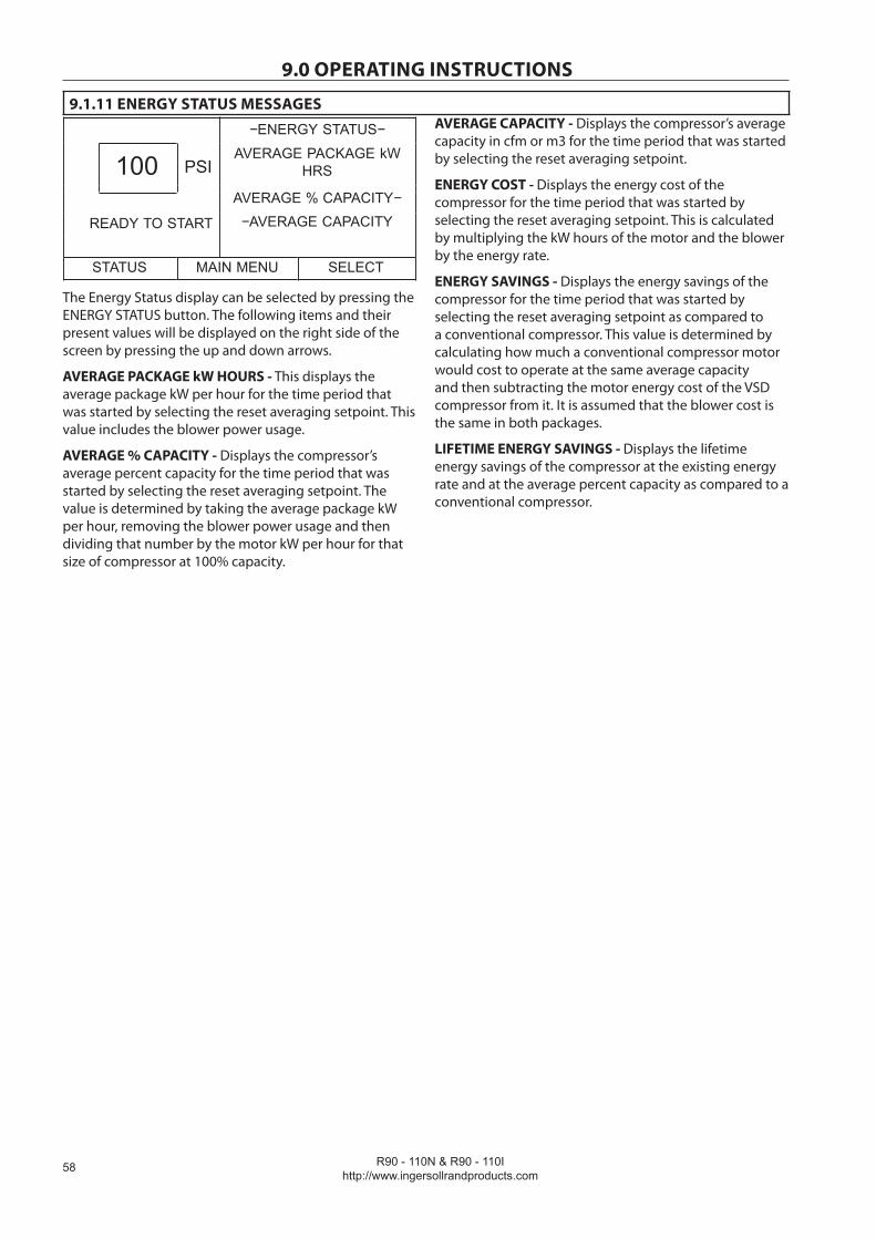
R90 - 110N & R90 - 110I http://www.ingersollrandproducts.com
��
9.0 OPERATING INSTRUCTIONS
9.1.11 ENERGY STATUS MESSAGES−ENERGY STATUS−
100 PSIAVERAGE PACKAGE kW
HRS
G % C CAVERAGE % CAPACITY−
READY TO START −AVERAGE CAPACITY
STATUS MAIN MENU SELECT
The Energy Status display can be selected by pressing the ENERGY STATUS button. The following items and their present values will be displayed on the right side of the screen by pressing the up and down arrows.
AVERAGE PACKAGE kW HOURS - This displays the average package kW per hour for the time period that was started by selecting the reset averaging setpoint. This value includes the blower power usage.
AVERAGE % CAPACITY - Displays the compressor’s average percent capacity for the time period that was started by selecting the reset averaging setpoint. The value is determined by taking the average package kW per hour, removing the blower power usage and then dividing that number by the motor kW per hour for that size of compressor at 100% capacity.
AVERAGE CAPACITY - Displays the compressor’s average capacity in cfm or m3 for the time period that was started by selecting the reset averaging setpoint.
ENERGY COST - Displays the energy cost of the compressor for the time period that was started by selecting the reset averaging setpoint. This is calculated by multiplying the kW hours of the motor and the blower by the energy rate.
ENERGY SAVINGS - Displays the energy savings of the compressor for the time period that was started by selecting the reset averaging setpoint as compared to a conventional compressor. This value is determined by calculating how much a conventional compressor motor would cost to operate at the same average capacity and then subtracting the motor energy cost of the VSD compressor from it. It is assumed that the blower cost is the same in both packages.
LIFETIME ENERGY SAVINGS - Displays the lifetime energy savings of the compressor at the existing energy rate and at the average percent capacity as compared to a conventional compressor.

R90 - 110N & R90 - 110Ihttp://www.ingersollrandproducts.com
�9
9.0 OPERATING INSTRUCTIONS
9.1.12 WARNINGS
When a WARNING occurs, a large question mark will flash on the display screen.
If multiple WARNINGS exist, the small up/down arrows will appear in the upper right corner of the display screen. The multiple WARNINGS can be seen by pressing the up and down arrow buttons. Pressing the STATUS button will display the CURRENT STATUS screen with the WARNING button indicating that a WARNING still exists.
A WARNING will not cause the unit to shut down. The unit will continue to run in its normal operation and the WARNING will remain displayed until reset.
A Warning needs to be reset by the operator by pressing the RESET button twice.
The possible Warning messages are as follows;
HIGH AIREND DISCHARGE TEMP - This will occur if the Airend Discharge exceeds 221° F/105° C and is not adjustable.
CHANGE COOLANT FILTER - This warning will occur if the high side pressure is 1.4 bar (20 psig) greater than the low side pressure.
CHANGE INLET FILTER - This will occur if the Inlet Vacuum is greater than 0.05 bar (0.7 psig).
CHANGE SEPR ELEMENT - This will occur if the pressure differential across the separator is 1.0 bar (12 psig).
SENSOR FAILURE - This will occur if a sensor is recognized as missing or broken.
HIGH DISCHARGE PRESS - Will occur if the unit is under the control of an external device, such as an ISC, and the discharge pressure is greater than the immediate stop pressure.
AUXILIARY WARNING 1 or 2 - Will occur if the auxiliary warning input closes.
REMOTE PRESSURE SENSOR FAILURE (option) - This will occur if the remote pressure sensor fails. If this happens, the lntellisys will start using the package discharge pressure sensor to measure system pressure.
CONDENSATE DRAIN ERROR - For units fitted with the no loss drain trap, occur if the condensate drain error contacts close while the unit is running.
HIGH VSD AMBIENT TEMPERATURE - This warning will occur if the VSD ambient temperature gets within 5% of the shutdown value.
HIGH SUMP PRESSURE - Occurs if the compressor is running, the compressor is warm, the package discharge pressure is at least 65 psi, and the sump pressure is more than 15 psi above the target pressure. The occurrence of this warning will cause the controller to evaluate the need to lower the compressor’s speed.
9.1.13 SERVICE WARNINGS
SERVICE - Service warnings occur when the unit has operated a certain number of hours, based on the total hours. Service warnings can have multiple levels, depending on the service level selection.
This will be set prior to the compressor being shipped from the factory. When a service warning occurs, contact your local Ingersoll Rand service representative.
9.1.14 INITIAL CHECK TRIPS:
The following trips will only occur when the machine is not running. These trips are related to high temperature, power loss, and sensor calibration. They will have the same display mode as other trips.
HIGH AIREND DISCH TEMP- Will occur if airend discharge temperature is greater than 95% of 109° C (228° F).
CHECK SETPOINTS - Will occur if the controller has determined that some of the data stored in memory contains unacceptable values.
INVALID CALIBRATION - Will occur if the sensor zero value is -10% to +1% of its scale. See Sensor Calibration.

R90 - 110N & R90 - 110I http://www.ingersollrandproducts.com
�0
9.0 OPERATING INSTRUCTIONS
9.1.15 TRIPSWhen a Trip occurs, a large exclamation mark in a triangle will flash on the display screen. The display message will indicate what caused the Trip.
The compressor will stop and cannot be re-started again until the trip condition no longer exists and the trip message reset.
Pressing the STATUS button will display the STATUS screen. The presence of the TRIP button indicates that a Trip condition still exists. Trip Status is the list of machine operating conditions that existed at the time of the Trip.
The name and value of each of the items listed can be seen by moving the list up and down using the arrow buttons. Pressing the TRIP button will return the display to the Trip screen and the RESET button.
The Trip needs to be reset by the operator by pressing the RESET button twice. Any exceptions to this are explained in the trip descriptions.
−TRIP STATUS−
100100 PSI PACKAGE DISCHPRESSURE
100 psi
STOPPED BYTRIP
PACKAGE DISCHARGETEMP
103 F
TRIP MAIN MENU
The possible Trip messages are as follows;
EMERGENCY STOP- This will occur if the Emergency Stop button is engaged. The button must be disengaged before the trip can be cleared.
BLOWER FAULT- This will occur if a blower fault is sensed.
HIGH AIREND DISCH TEMP- This will occur if the airend discharge temperature is greater than 109° C (228° F).
REMOTE START FAILURE- This will occur if the Remote Start button is pressed after the machine is running or if the Remote Start button remains closed.
REMOTE STOP FAILURE- This will occur if the Remote Stop button remains open and either Start button is pressed.
SENSOR FAILURE - This will occur if a sensor is recognized as missing or broken.
VSD FAULT - The VSD fault is read from the drive. The Intellisys will read the status menu of the variable speed drive. If a fault condition is returned in the status information, the Intellisys will issue a VSD FAULT trip and display the number of the fault condition.
STOP FAILURE - This will occur if the compressor should be stopped but the motor is still running above minimum speed 4 seconds after the stop signal is given.
HIGH START PRESSURE - If the sump pressure is above 100 psi (6.9 bar) when the compressor starts, the Intellisys will open the blowdown valve during the first few seconds of starting (3 to 7 seconds). If the sump pressure does not fall to 100 psi (6.9 bar) during that time period, this shutdown will occur.
CHECK MOTOR ROTATION - This will occur if the Intellisys reads a negative speed from the VSD when starting.
VSD COMMUNICATION FAILURE - This will occur if the Intellisys does not receive a response from the VSD when requesting information. This trip will take about 8 seconds to occur.
VSD INITIALIZATION FAULT - Will occur if the Intellisys is unable to establish communications with the VSD after a power up.
LOW SUMP PRESSURE - Will occur if the compressor is operating at or above the minimum speed and the sump pressure drops below 15psi (1.03 bar) for 15 seconds.
REPLACE COOLANT FILTER - This will occur if the coolant filter is blocked and requires changing.
INCORRECT VSD TYPE - Will occur at power up if the VSD type does not match the size of the compressor.
CONTROL POWER LOSS - This will occur if the compressor should be running and the AC input voltage, as read from the VSD, falls below 100 VAC. There is a delay of 2 seconds on this trip in case the power quickly returns. Phase monitor can also cause this trip.
HIGH INTERSTAGE PRESSURE - If the interstage pressure is over 100psi while the unit is running and the unit is a 2-stage.
HIGH COOLANT FILTER PRESSURE DROP - Occurs if the unit has been running for at least 7 seconds, the compressor is warm, already has a change coolant filter warning, the motor is running, and the coolant filter pressure drop is greater than 35 psi.
HIGH INLET VACUUM - Occurs if the compressor is running loaded, the motor is running, and the inlet vacuum is greater than 1.8 psi (vacuum).
HIGH SUMP PRESSURE - Occurs if the compressor is running, the compressor is warm, and any one of the 3 following conditions exist.
The sump pressure is above the maximum offline pressure by 25 psi.
The separator pressure drop is measured to be more than 25 psi and the package discharge pressure is at least 65 psi.
The sump pressure is above 170 psi.
1.
2.
3.
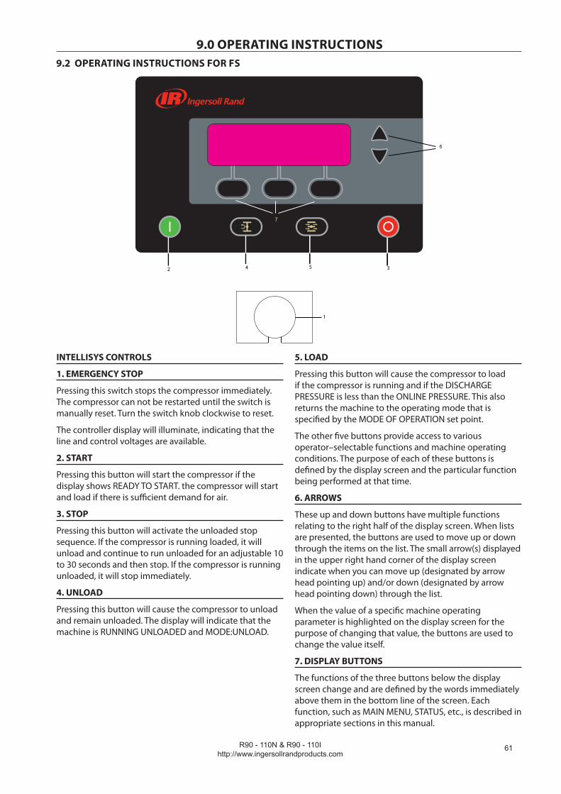
R90 - 110N & R90 - 110Ihttp://www.ingersollrandproducts.com
�1
9.0 OPERATING INSTRUCTIONS9.2 OPERATING INSTRUCTIONS FOR FS
INTELLISYS CONTROLS
1. EMERGENCY STOP
Pressing this switch stops the compressor immediately. The compressor can not be restarted until the switch is manually reset. Turn the switch knob clockwise to reset.
The controller display will illuminate, indicating that the line and control voltages are available.
2. START
Pressing this button will start the compressor if the display shows READY TO START. the compressor will start and load if there is sufficient demand for air.
3. STOP
Pressing this button will activate the unloaded stop sequence. If the compressor is running loaded, it will unload and continue to run unloaded for an adjustable 10 to 30 seconds and then stop. If the compressor is running unloaded, it will stop immediately.
4. UNLOAD
Pressing this button will cause the compressor to unload and remain unloaded. The display will indicate that the machine is RUNNING UNLOADED and MODE:UNLOAD.
5. LOAD
Pressing this button will cause the compressor to load if the compressor is running and if the DISCHARGE PRESSURE is less than the ONLINE PRESSURE. This also returns the machine to the operating mode that is specified by the MODE OF OPERATION set point.
The other five buttons provide access to various operator–selectable functions and machine operating conditions. The purpose of each of these buttons is defined by the display screen and the particular function being performed at that time.
6. ARROWS
These up and down buttons have multiple functions relating to the right half of the display screen. When lists are presented, the buttons are used to move up or down through the items on the list. The small arrow(s) displayed in the upper right hand corner of the display screen indicate when you can move up (designated by arrow head pointing up) and/or down (designated by arrow head pointing down) through the list.
When the value of a specific machine operating parameter is highlighted on the display screen for the purpose of changing that value, the buttons are used to change the value itself.
7. DISPLAY BUTTONS
The functions of the three buttons below the display screen change and are defined by the words immediately above them in the bottom line of the screen. Each function, such as MAIN MENU, STATUS, etc., is described in appropriate sections in this manual.
1
4 5 32
6
7
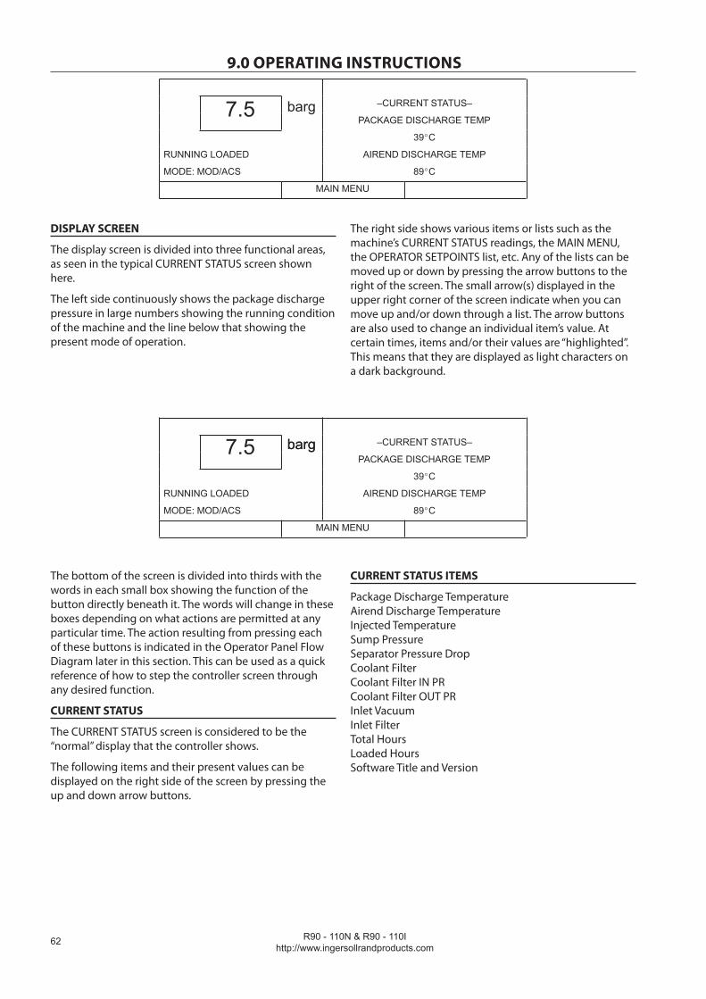
R90 - 110N & R90 - 110Ihttp://www.ingersollrandproducts.com
��
9.0 OPERATING INSTRUCTIONS
–CURRENT STATUS–7.5 bargPACKAGE DISCHARGE TEMP
39 C
RUNNING LOADED AIREND DISCHARGE TEMP
MODE: MOD/ACS 89 C
MAIN MENU
DISPLAY SCREEN
The display screen is divided into three functional areas, as seen in the typical CURRENT STATUS screen shown here.
The left side continuously shows the package discharge pressure in large numbers showing the running condition of the machine and the line below that showing the present mode of operation.
The right side shows various items or lists such as the machine’s CURRENT STATUS readings, the MAIN MENU, the OPERATOR SETPOINTS list, etc. Any of the lists can be moved up or down by pressing the arrow buttons to the right of the screen. The small arrow(s) displayed in the upper right corner of the screen indicate when you can move up and/or down through a list. The arrow buttons are also used to change an individual item’s value. At certain times, items and/or their values are “highlighted”. This means that they are displayed as light characters on a dark background.
barg –CURRENT STATUS–7.5 bargPACKAGE DISCHARGE TEMP
39 C
RUNNING LOADED AIREND DISCHARGE TEMP
MODE: MOD/ACS 89 C
MAIN MENU
The bottom of the screen is divided into thirds with the words in each small box showing the function of the button directly beneath it. The words will change in these boxes depending on what actions are permitted at any particular time. The action resulting from pressing each of these buttons is indicated in the Operator Panel Flow Diagram later in this section. This can be used as a quick reference of how to step the controller screen through any desired function.
CURRENT STATUS
The CURRENT STATUS screen is considered to be the “normal” display that the controller shows.
The following items and their present values can be displayed on the right side of the screen by pressing the up and down arrow buttons.
CURRENT STATUS ITEMS
Package Discharge Temperature Airend Discharge Temperature Injected Temperature Sump Pressure Separator Pressure Drop Coolant Filter Coolant Filter IN PR Coolant Filter OUT PR Inlet Vacuum Inlet Filter Total Hours Loaded Hours Software Title and Version

R90 - 110N & R90 - 110Ihttp://www.ingersollrandproducts.com
��
9.0 OPERATING INSTRUCTIONS
OPERATOR SETPOINTS
(2)
OPERATOR SETPOINTS ITEM
(3)
MAIN MENU (1)
CURRENTSTATUS
OPTIONS(2)
OPTIONS ITEM(3)
SENSOR CALIBRATION
(2)
SENSOR CALIBRATION ITEM
(4)
TRIP HISTORY(2)
TRIP HISTORYITEM
(3)
The controller automatically returns the display to this CURRENT STATUS screen from other screens if no buttons are pressed within 30 seconds.
The MAIN MENU screen can be accessed from the CURRENT STATUS screen by pressing the MAIN MENU button, identified by the words “MAIN MENU” in the bottom line of the screen directly above the centre button.
NOTE: Use the UP and DOWN arrows to move between selections. Items will be highlighted in inverse display mode.
(1) Selecting the highlighted item will display the cor-responding menu.
(2) Selecting the highlighted item will place the value in edit mode. This is indicated by only the value being displayed in inverse display mode.
(3) The UP and DOWN arrows will alter the value. Depressing “Cancel” will exit the edit mode and leave the value unchanged. Depressing “Set” will save the new value and flash the value to indicate acceptance.
(4) Depressing “Cancel” will exit the calibration mode. Depressing “Calibrate” will calibrate the selected sen-sor. Ensure that the unit is stopped and fully depressurised first.
(5) Use the UP and DOWN arrows to scroll through the list of status items.
–MAIN MENU–
barg7.5 bargOPERATOR SETPOINTS
OPTIONS
READY TO START SENSOR CALIBRATION
TRIP HISTORY
STATUS SELECT
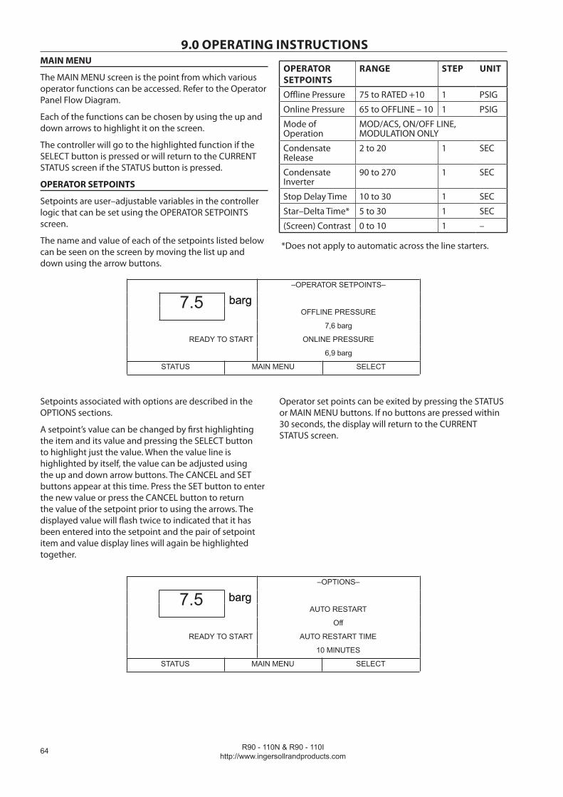
R90 - 110N & R90 - 110Ihttp://www.ingersollrandproducts.com
��
9.0 OPERATING INSTRUCTIONSMAIN MENU
The MAIN MENU screen is the point from which various operator functions can be accessed. Refer to the Operator Panel Flow Diagram.
Each of the functions can be chosen by using the up and down arrows to highlight it on the screen.
The controller will go to the highlighted function if the SELECT button is pressed or will return to the CURRENT STATUS screen if the STATUS button is pressed.
OPERATOR SETPOINTS
Setpoints are user–adjustable variables in the controller logic that can be set using the OPERATOR SETPOINTS screen.
The name and value of each of the setpoints listed below can be seen on the screen by moving the list up and down using the arrow buttons.
OPERATOR SETPOINTS
RANGE STEP UNIT
Offline Pressure 75 to RATED +10 1 PSIG
Online Pressure 65 to OFFLINE – 10 1 PSIG
Mode of Operation
MOD/ACS, ON/OFF LINE, MODULATION ONLY
Condensate Release
2 to 20 1 SEC
Condensate Inverter
90 to 270 1 SEC
Stop Delay Time 10 to 30 1 SEC
Star–Delta Time* 5 to 30 1 SEC
(Screen) Contrast 0 to 10 1 –
*Does not apply to automatic across the line starters.
–OPERATOR SETPOINTS–
barg7.5 bargOFFLINE PRESSURE
7,6 barg
READY TO START ONLINE PRESSURE
6,9 barg
STATUS MAIN MENU SELECT
Setpoints associated with options are described in the OPTIONS sections.
A setpoint’s value can be changed by first highlighting the item and its value and pressing the SELECT button to highlight just the value. When the value line is highlighted by itself, the value can be adjusted using the up and down arrow buttons. The CANCEL and SET buttons appear at this time. Press the SET button to enter the new value or press the CANCEL button to return the value of the setpoint prior to using the arrows. The displayed value will flash twice to indicated that it has been entered into the setpoint and the pair of setpoint item and value display lines will again be highlighted together.
Operator set points can be exited by pressing the STATUS or MAIN MENU buttons. If no buttons are pressed within 30 seconds, the display will return to the CURRENT STATUS screen.
–OPTIONS–
barg7.5 bargAUTO RESTART
Off
READY TO START AUTO RESTART TIME
10 MINUTES
STATUS MAIN MENU SELECT
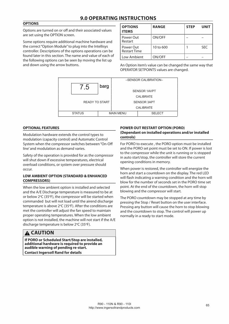
R90 - 110N & R90 - 110Ihttp://www.ingersollrandproducts.com
��
9.0 OPERATING INSTRUCTIONSOPTIONS
Options are turned on or off and their associated values are set using the OPTION screen.
Some options require additional machine hardware and the correct “Option Module” to plug into the Intellisys controller. Descriptions of the options operations can be found later in this section. The name and value of each of the following options can be seen by moving the list up and down using the arrow buttons.
OPTIONS ITEMS
RANGE STEP UNIT
Power Out Restart
ON/OFF – –
Power Out Restart Time
10 to 600 1 SEC
Low Ambient ON/OFF – –
An Option item’s value can be changed the same way that OPERATOR SETPOINTS values are changed.
–SENSOR CALIBRATION–
barg7.5 bargSENSOR 1AVPT
CALIBRATE
READY TO START SENSOR 3APT
CALIBRATE
STATUS MAIN MENU SELECT
OPTIONAL FEATURES
Modulation hardware extends the control types to modulation (capacity control) and Automatic Control System when the compressor switches between “On-Off line’ and modulation as demand varies.
Safety of the operation is provided for as the compressor will shut down if excessive temperatures, electrical overload conditions, or system over pressure should occur.
LOW AMBIENT OPTION (STANDARD & ENHANCED COMPRESSORS)
When the low ambient option is installed and selected and the A/E Discharge temperature is measured to be at or below 2oC (35oF), the compressor will be started when commanded but will not load until the airend discharge temperature is above 2oC (35oF). After the conditions are met the controller will adjust the fan speed to maintain proper operating temperatures. When the low ambient option is not installed, the machine will not start if the A/E discharge temperature is below 2oC (35oF).
CAUTIONIf PORO or Scheduled Start/Stop are installed, additional hardware is required to provide an audible warning of pending re-start.Contact Ingersoll Rand for details
POWER OUT RESTART OPTION (PORO) (Dependant on installed operations and/or installed controls)
For PORO to execute , the PORO option must be installed and the PORO set point must be set to ON. If power is lost to the compressor while the unit is running or is stopped in auto start/stop, the controller will store the current opening conditions in memory.
When power is restored, the controller will energize the horn and start a countdown on the display. The red LED will flash indicating a warning condition and the horn will blow for the number of seconds set in the PORO time set point. At the end of the countdown, the horn will stop blowing and the compressor will start.
The PORO countdown may be stopped at any time by pressing the Stop / Reset button on the user interface. Pressing any button will cause the horn to stop blowing and the countdown to stop. The control will power up normally in a ready to start mode.
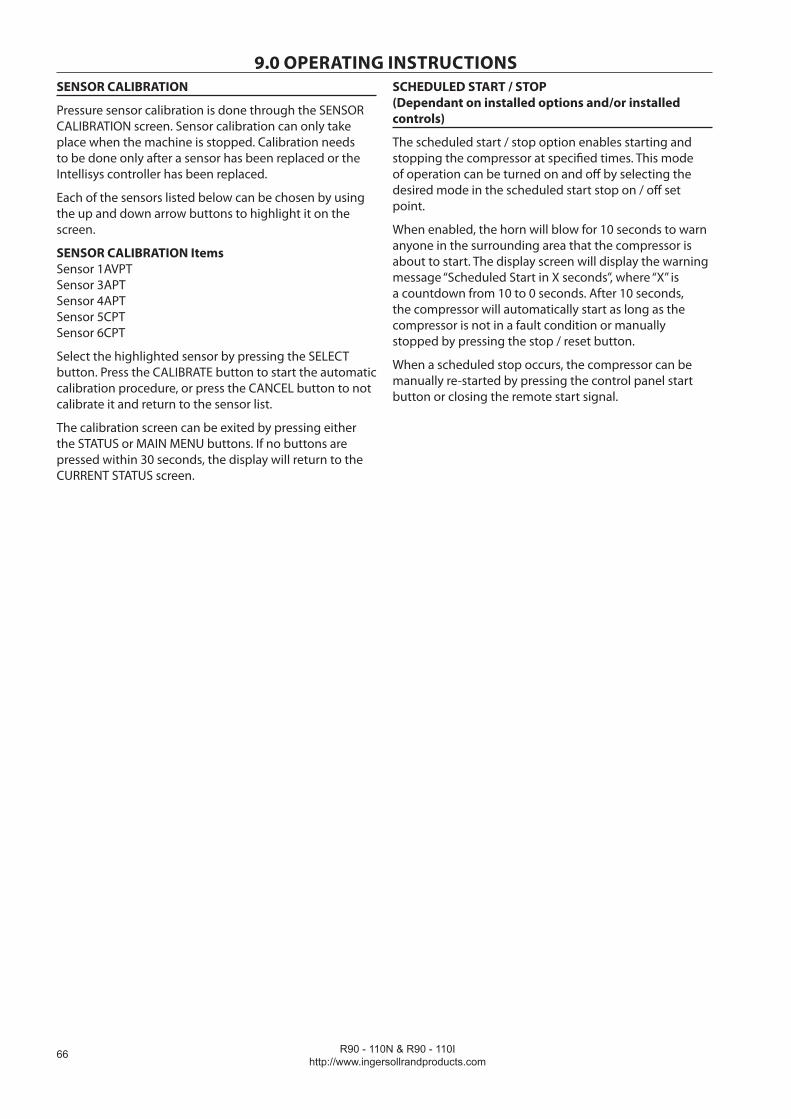
R90 - 110N & R90 - 110Ihttp://www.ingersollrandproducts.com
��
9.0 OPERATING INSTRUCTIONSSENSOR CALIBRATION
Pressure sensor calibration is done through the SENSOR CALIBRATION screen. Sensor calibration can only take place when the machine is stopped. Calibration needs to be done only after a sensor has been replaced or the Intellisys controller has been replaced.
Each of the sensors listed below can be chosen by using the up and down arrow buttons to highlight it on the screen.
SENSOR CALIBRATION Items Sensor 1AVPT Sensor 3APT Sensor 4APT Sensor 5CPT Sensor 6CPT
Select the highlighted sensor by pressing the SELECT button. Press the CALIBRATE button to start the automatic calibration procedure, or press the CANCEL button to not calibrate it and return to the sensor list.
The calibration screen can be exited by pressing either the STATUS or MAIN MENU buttons. If no buttons are pressed within 30 seconds, the display will return to the CURRENT STATUS screen.
SCHEDULED START / STOP (Dependant on installed options and/or installed controls)
The scheduled start / stop option enables starting and stopping the compressor at specified times. This mode of operation can be turned on and off by selecting the desired mode in the scheduled start stop on / off set point.
When enabled, the horn will blow for 10 seconds to warn anyone in the surrounding area that the compressor is about to start. The display screen will display the warning message “Scheduled Start in X seconds”, where “X” is a countdown from 10 to 0 seconds. After 10 seconds, the compressor will automatically start as long as the compressor is not in a fault condition or manually stopped by pressing the stop / reset button.
When a scheduled stop occurs, the compressor can be manually re-started by pressing the control panel start button or closing the remote start signal.
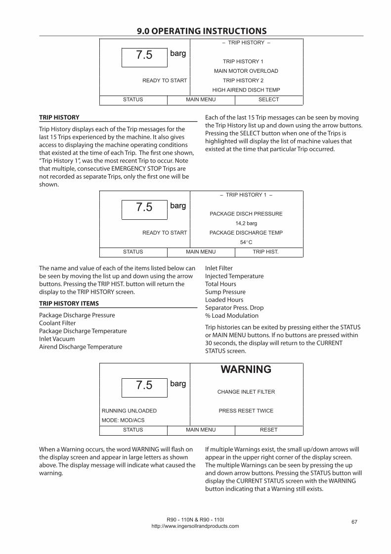
R90 - 110N & R90 - 110Ihttp://www.ingersollrandproducts.com
��
9.0 OPERATING INSTRUCTIONS– TRIP HISTORY –
barg7.5 bargTRIP HISTORY 1
MAIN MOTOR OVERLOAD
READY TO START TRIP HISTORY 2
HIGH AIREND DISCH TEMP
STATUS MAIN MENU SELECT
TRIP HISTORY
Trip History displays each of the Trip messages for the last 15 Trips experienced by the machine. It also gives access to displaying the machine operating conditions that existed at the time of each Trip. The first one shown, “Trip History 1”, was the most recent Trip to occur. Note that multiple, consecutive EMERGENCY STOP Trips are not recorded as separate Trips, only the first one will be shown.
Each of the last 15 Trip messages can be seen by moving the Trip History list up and down using the arrow buttons. Pressing the SELECT button when one of the Trips is highlighted will display the list of machine values that existed at the time that particular Trip occurred.
– TRIP HISTORY 1 –
barg7.5 bargPACKAGE DISCH PRESSURE
14,2 barg
READY TO START PACKAGE DISCHARGE TEMP
54 C
STATUS MAIN MENU TRIP HIST.
The name and value of each of the items listed below can be seen by moving the list up and down using the arrow buttons. Pressing the TRIP HIST. button will return the display to the TRIP HISTORY screen.
TRIP HISTORY ITEMS
Package Discharge Pressure Coolant Filter Package Discharge Temperature Inlet Vacuum Airend Discharge Temperature
Inlet Filter Injected Temperature Total Hours Sump Pressure Loaded Hours Separator Press. Drop % Load Modulation
Trip histories can be exited by pressing either the STATUS or MAIN MENU buttons. If no buttons are pressed within 30 seconds, the display will return to the CURRENT STATUS screen.
WARNINGbarg7.5 barg
CHANGE INLET FILTER
RUNNING UNLOADED PRESS RESET TWICE
MODE: MOD/ACS
STATUS MAIN MENU RESET
When a Warning occurs, the word WARNING will flash on the display screen and appear in large letters as shown above. The display message will indicate what caused the warning.
If multiple Warnings exist, the small up/down arrows will appear in the upper right corner of the display screen. The multiple Warnings can be seen by pressing the up and down arrow buttons. Pressing the STATUS button will display the CURRENT STATUS screen with the WARNING button indicating that a Warning still exists.

R90 - 110N & R90 - 110Ihttp://www.ingersollrandproducts.com
��
9.0 OPERATING INSTRUCTIONS–CURRENT STATUS–
barg7.5 bargPACKAGE DISCHARGE TEMP
39,4 C
RUNNING UNLOADED AIREND DISCHARGE TEMP
MODE: MOD/ACS 89,4 C
WARNING MAIN MENU
Pressing the WARNING button will return the display to the WARNING screen and the RESET button.
A Warning needs to be reset by the operator by pressing the RESET button twice.
The possible Warning messages are as follows;
AIREND DISCHARGE TEMP – This will occur if the Airend Discharge (2ATT) exceeds 97% of the alarm limit, 228°F (109°C) and is not adjustable.
CHANGE COOLANT FILTER – This warning will occur if the high side pressure is 20 psig (1,4 bar) greater than the low side pressure of 1 DPS and the Injected Coolant temperature (2CTT) is greater than 120°F (49°C).
CHANGE INLET FILTER – This will occur if the Inlet Vacuum (1AVPT) is greater than 0,7 psig (0,05 bar) and the machine is fully loaded (inlet valve is completely open).
CHANGE SEPR ELEMENT – This warning will occur if the pressure on the Separator (3APT) is 15 psig (1,0 bar) greater than the pressure at the Package Discharge (4APT) and the machine is fully loaded.
TRIPbarg7.5 barg
HIGH AIREND DSCH TEMP
109,4 C
STOPPED BY TRIP
MODE: MOD/ACS PRESS RESET TWICE
STATUS MAIN MENU RESET
HIGH DISCHARGE PRESS – This can occur if the machine’s loading function is being controlled by a host device such as a sequencer or an ISC. This warning will occur when the package discharge pressure is above the maximum offline pressure (rated pressure plus 3 psig (0,2 bar)) for more than 3 seconds. This warning will cause the compressor to unload. The host device will not be able to load the compressor until the package discharge pressure falls to the rated pressure of the machine.
SENSOR FAILURE 4ATT – This will occur if the Package Discharge Temperature Sensor (4ATT) is missing or broken.
TRIPS
When an Trip occurs, the word TRIP will flash on the display screen and appear in large letters as shown above. The display message will indicate what caused the Trip.
Pressing the STATUS button will display the STATUS screen. The presence of the TRIP button indicates that an Trip condition still exists. Trip Status is the list of machine operating conditions that existed at the time of the Trip.
– TRIP STATUS –
barg7.5 bargPACKAGE DISCH PRESSURE
7,0 barg
STOPPED BY TRIP PACKAGE DISCHARGE TEMP
MODE: MOD/ACS 39,4 C
ALARM MAIN MENU

R90 - 110N & R90 - 110Ihttp://www.ingersollrandproducts.com
�9
9.0 OPERATING INSTRUCTIONSThe name and value of each of the items listed can be seen by moving the list up and down using the arrow buttons. Pressing the TRIP button will return the display to the Trip screen and the RESET button.
The Trip needs to be reset by the operator by pressing the RESET button twice. Any exceptions to this are explained in the Trip descriptions.
The possible Trip messages are as follows;
CHECK MOTOR ROTATION – This will occur if the machine is started and the compressor has incorrect rotation.
CONTROL POWER LOSS – This will occur if the controller detects a loss of the 110 VAC control power.
EMERGENCY STOP– This will occur if the Emergency Stop button is engaged. The button must be disengaged before the trip can be cleared.
FAN MOTOR OVERLOAD– This will occur if a fan motor overload is sensed.
HIGH AIREND DISCH TEMP– This will occur if the airend discharge temperature is greater than 228°F (109°C).
HIGH SUMP PRESSURE– This will occur if the sump pressure is above offline pressure by 25 psig and sump pressure drop is more than 25 psig. Can also occur if sump pressure is above 165 psig.
LOW SUMP AIR PRESSURE– This will occur if the
machine is running fully loaded and the sump pressure drops below 20 psig (1,4 bar).
LOW UNLOAD SUMP PRESS– This will occur if the machine is running unloaded and the sump pressure is less than 15 psig (1,0 bar) for 15 seconds.
MAIN MOTOR OVERLOAD– This will occur if a drive motor overload is sensed.
MEMORY FAULT– This will occur if the controller has determined some of the data stored in memory contains unacceptable values. When this occurs, the sensors should be calibrated and all the set points checked. It is normal for this trip to occur after changing controller software.
REMOTE START FAILURE– This will occur if the Remote Start button is pressed after the machine is running or if the Remote Start button remains closed.
REMOTE STOP FAILURE– This will occur if the Remote Stop button remains open and either Start button is pressed.
SENSOR FAILURE 1AVPT (or 3APT, 4APT, 2CPT,5CPT,6CPT 2ATT)– This will occur if a sensor is recognised as missing or broken. This does not apply to sensor 4ATT.
HIGH INLET VACUUM – This will occurs if inlet vacuum is greater than 1.8 psig for units with high dust factor, the threshold is 1.8 psig.
T5461 Revision 00 12/94

R90 - 110N & R90 - 110Ihttp://www.ingersollrandproducts.com
�0
9.0 OPERATING INSTRUCTIONSPRIOR TO STARTING
Refer to the diagram T5461
WARNINGEnsure that all protective covers/guards are in place before attempting to start the machine.
Check the coolant level in the sight tube/glass. Add coolant if necessary.
Ensure that the discharge air isolation valve is open.
Switch on the main electrical isolation switch. The power on indicator will illuminate, indicating that the line and control voltages are available.
1.
2.
3.
1
4 5 32
6
7
STARTING THE MACHINE
Upon power up, the Intellisys will carry out a series of checks, and the message CHECKING MACHINE will show on the display. If all the check parameters are satisfactory, the display will then show READY TO START.
Depress the start button (2) on the Intellisys unit. The machine will start and automatically load.
STOPPING THE MACHINE
Depress the STOP button (3) which will automatically unload the compressor for 10 seconds before stopping.
Switch off the main electrical isolation switch.
STOPPING THE MACHINE IN AN EMERGENCY
If the machine has to be stopped in an emergency DEPRESS THE EMERGENCY STOP BUTTON (1) LOCATED ON THE INSTRUMENT PANEL.
This will over–ride the normal unload/stop button and will immediately stop the machine without the 10 second delay.
CAUTIONNever allow the machine to stand idle with pressure in the system.
RE–STARTING AFTER AN EMERGENCY
If the unit has been switched off because of a machine malfunction, then identify and correct the fault before attempting to re–start.
If the unit has been switched off for reasons of safety, then ensure that the machine can be operated safely before re–starting.
Refer to the PRIOR TO STARTING and STARTING THE MACHINE instructions earlier in this section before re–starting the machine.

R90 - 110N & R90 - 110Ihttp://www.ingersollrandproducts.com
�1
10.0 MAINTENANCE
10.1 MAINTENANCE PROMPTS
The service warning and flashing LED will appear at intervals, dependant on the service level selected. Refer to operating instructions.
For service level 1, when a “Service Required” warning is issued, the warning can be reset the same way as any other warning.
For service level 2, when a “Service Required” warning is issued, the customer can only reset the warning for 24 hours by pressing the “set” button.
Ingersoll Rand service engineers will master reset the warning after completing the service work.
The service warning will return each subsequent 2000 hours.
The machine will be master reset after service work conducted prior to the 2000 hour interval to prevent false indication.
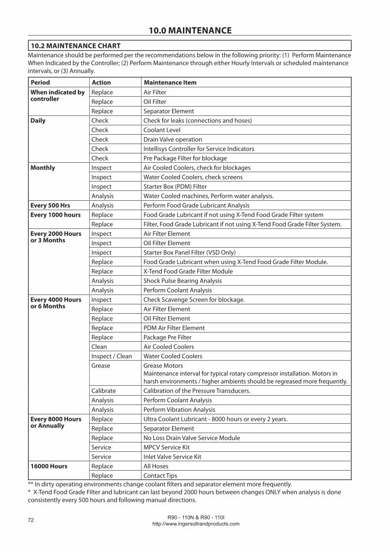
R90 - 110N & R90 - 110Ihttp://www.ingersollrandproducts.com
��
10.0 MAINTENANCE
10.2 MAINTENANCE CHARTMaintenance should be performed per the recommendations below in the following priority: (1) Perform Maintenance When Indicated by the Controller; (2) Perform Maintenance through either Hourly Intervals or scheduled maintenance intervals, or (3) Annually.
Period Action Maintenance ItemWhen indicated by controller
Replace Air FilterReplace Oil FilterReplace Separator Element
Daily Check Check for leaks (connections and hoses)Check Coolant LevelCheck Drain Valve operation Check Intellisys Controller for Service IndicatorsCheck Pre Package Filter for blockage
Monthly Inspect Air Cooled Coolers, check for blockagesInspect Water Cooled Coolers, check screensInspect Starter Box (PDM) FilterAnalysis Water Cooled machines, Perform water analysis.
Every 500 Hrs Analysis Perform Food Grade Lubricant AnalysisEvery 1000 hours Replace Food Grade Lubricant if not using X-Tend Food Grade Filter system
Replace Filter, Food Grade Lubricant if not using X-Tend Food Grade Filter System.Every 2000 Hours or 3 Months
Inspect Air Filter ElementInspect Oil Filter ElementInspect Starter Box Panel Filter (VSD Only)Replace Food Grade Lubricant when using X-Tend Food Grade Filter Module.Replace X-Tend Food Grade Filter ModuleAnalysis Shock Pulse Bearing AnalysisAnalysis Perform Coolant Analysis
Every 4000 Hours or 6 Months
Inspect Check Scavenge Screen for blockage.Replace Air Filter ElementReplace Oil Filter ElementReplace PDM Air Filter ElementReplace Package Pre FilterClean Air Cooled CoolersInspect / Clean Water Cooled CoolersGrease Grease Motors
Maintenance interval for typical rotary compressor installation. Motors in harsh environments / higher ambients should be regreased more frequently.
Calibrate Calibration of the Pressure Transducers.Analysis Perform Coolant AnalysisAnalysis Perform Vibration Analysis
Every 8000 Hours or Annually
Replace Ultra Coolant Lubricant - 8000 hours or every 2 years.Replace Separator ElementReplace No Loss Drain Valve Service ModuleService MPCV Service KitService Inlet Valve Service Kit
16000 Hours Replace All HosesReplace Contact Tips
** In dirty operating environments change coolant filters and separator element more frequently. * X-Tend Food Grade Filter and lubricant can last beyond 2000 hours between changes ONLY when analysis is done consistently every 500 hours and following manual directions.
R90 - 110N & R90 - 110Ihttp://www.ingersollrandproducts.com
��
10.0 MAINTENANCE
10.3 MAINTENANCE PROCEDURES
CAUTIONBefore beginning any work on the compressor, read and understand the safety instructions earlier on in this manual. Open, lock and tag the main electrical disconnect and close the isolation valve on the compressor discharge. Do not under any circumstances open any drain valve or remove components from the compres-sor until this has been carried out. Ensure that all pressure has been vented from the compressor. Verify this by slowly unscrewing the coolant fill cap one turn. Unscrewing the fill cap opens a vent hole, drilled in the cap, allowing pressure to release to atmosphere. Do not remove the fill cap until all pressure has vented from the unit. Note that pipework downstream of the separator tank may still contain pressure that must also be vented to atmosphere before beginning any work.
CAUTIONWhen using any form of liquid for cleaning, ensure that all electrical components are protected orcovered to prevent ingress of liquid.
WARNINGFor VSD this compressor contains a variable frequency drive. When it is switched off and the motor is stopped, the internal capacitors store a potentially lethal high voltage. DO NOT REMOVE THE DRIVE COVER or attempt any work on the drive unless trained. There are no user serviceable items behind the cover.
DANGERFor VSD this compressor contains a variable frequency drive. When it is switched off and the motor is stopped, the internal capacitors store a potentially lethal high voltage electric charge which gradually falls to zero over time. After switching off the machine at its local isolator WAIT AT LEAST 15 MINUTES for the capacitors to fully discharge before opening the power drive module doors.
WARNINGFor VSD the compressor can operate in a pressurised shutdown mode. If the compressor stops automatically, the airend, separator tank and oil system can contain high pressure air. This can be relieved by pressing the emergency stop button and can be verified by unscrewing the coolant fill plug which has a vent hole through which any residual pressure will be vented. Downstream of the separator tank may still contain system pres-sure which must also be vented.
WARNINGUse suitable equipment for lifting heavy items and ensure loose components are adequately supported to eliminate risk of dropping.
WARNINGFor VSD the motor rotor contains a powerful magnetic field. This field can effect the operation of digital devices such as watches, mobile phones etc. Assembly or handling of the rotor should not be attempted by personnel with cardiac pacemakers, defibrillators or other implanted electronic medical device.
R90 - 110N & R90 - 110Ihttp://www.ingersollrandproducts.com
��
10.0 MAINTENANCECompressed air can be dangerous if incorrectly handled. Before doing any work on the unit, ensure that all pressure is vented from the system and that the machine cannot be started accidentally.
Ensure that maintenance personnel are adequately trained, competent and have read the Maintenance Manuals.
Prior to attempting any maintenance work, ensure that:-
all air pressure is fully discharged and isolated from the system. If the automatic blowdown valve is used for this purpose, then allow enough time for it to complete the operation.the machine cannot be started accidentally or otherwise, by posting warning signs and/or fitting appropriate anti-start devices.all residual electrical power sources (mains and battery) are isolated.
Prior to opening or removing panels or covers to work inside a machine, ensure that:-
anyone entering the machine is aware of the reduced level of protection and the additional hazards, including hot surfaces and intermittently moving parts.the machine cannot be started accidentally or otherwise, by posting warning signs and/or fitting appropriate anti-start devices.
•
•
•
•
•
Prior to attempting any maintenance work on a running machine, ensure that:-
the work carried out is limited to only those tasks which require the machine to run.the work carried out with safety protection devices disabled or removed is limited to only those tasks which require the machine to be running with safety protection devices disabled or removed.all hazards present are known (e.g. pressurized components, electrically live components, removed panels, covers and guards, extreme temperatures, inflow and outflow of air, intermittently moving parts, safety valve discharge etc.).appropriate personal protective equipment is worn.loose clothing, jewelry, long hair etc. is made safe.warning signs indicating that Maintenance Work is in Progress are posted in a position that can be clearly seen.
Upon completion of maintenance tasks and prior to returning the machine into service, ensure that:-
the machine is suitably tested.all guards and safety protection devices are refitted.all panels are replaced, canopy and doors closed.hazardous materials are effectively contained and disposed of.
•
•
•
•••
••••

R90 - 110N & R90 - 110Ihttp://www.ingersollrandproducts.com
��
10.0 MAINTENANCE
10.4 ROUTINE MAINTENANCE
This section refers to the various components which require periodic maintenance and replacement.
For all other maintenance, contact your local Ingersoll Rand office, Distributor or Customer Center.
Refer to safety information and maintenance procedures prior to carrying out any of the maintenance in the following sections.
Prior to starting
Coolant level checking procedure
The coolant level should be checked daily. A coolant level sight glass is located on the side of the separator tank and while the machine is running on load, coolant should always be visible in the sight glass. The normal position is half way. The machine must running for at least 40 seconds for this check.
Stop the machine, insure sump pressure is 0 psig and ensure coolant is still visible in the sight glass.
Adding coolant
Run the compressor for a minimum of 40 seconds, the coolant level should be visible in the sight glass. If not, stop the compressor, depressurize by isolating the compressor from the system, pressing the emergency stop to vent the separator tank & airend (FS units can take more than 2 min to fully de-pressurize once stopped) , slowly unscrew the coolant fill plug to verify all pressure has been released and add coolant. Replace the coolant fill plug, restart the compressor and recheck the coolant level. Repeat until the coolant level is visible in the sight glass with the compressor both running and stopped.
Do not add coolant through the intake of the compressor, as this can result in overfilling, saturation of the separator filter element, and coolant carry-over downstream.
DANGERUnder no circumstance should the compressor be operated with the coolant fill plug removed.
Coolant change procedure
WARNINGThe coolant filter and coolant may be hot!
Draining Coolant
It is better to drain the coolant immediately after the compressor has been operating as the liquid will drain faster and any contaminant will still be in suspension
Install a drain hose (not supplied) in end of drain valve and place end of hose in a suitable container.Open drain valve to start drainage.After drainage, remove hose and close valve.Can also drain coolant from( air cooled only) oil cooler by removing plug.Can also drain additional coolant from airend by removing plug in airend discharge elbow.
•
•••
•
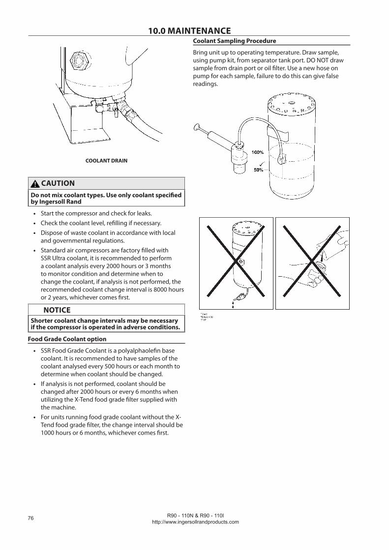
R90 - 110N & R90 - 110Ihttp://www.ingersollrandproducts.com
��
10.0 MAINTENANCE
COOLANT DRAIN
CAUTIONDo not mix coolant types. Use only coolant specified by Ingersoll Rand
Start the compressor and check for leaks.Check the coolant level, refilling if necessary.Dispose of waste coolant in accordance with local and governmental regulations.Standard air compressors are factory filled with SSR Ultra coolant, it is recommended to perform a coolant analysis every 2000 hours or 3 months to monitor condition and determine when to change the coolant, if analysis is not performed, the recommended coolant change interval is 8000 hours or 2 years, whichever comes first.
NOTICEShorter coolant change intervals may be necessary if the compressor is operated in adverse conditions.
Food Grade Coolant option
SSR Food Grade Coolant is a polyalphaolefin base coolant. It is recommended to have samples of the coolant analysed every 500 hours or each month to determine when coolant should be changed.If analysis is not performed, coolant should be changed after 2000 hours or every 6 months when utilizing the X-Tend food grade filter supplied with the machine.For units running food grade coolant without the X-Tend food grade filter, the change interval should be 1000 hours or 6 months, whichever comes first.
•••
•
•
•
•
Coolant Sampling Procedure
Bring unit up to operating temperature. Draw sample, using pump kit, from separator tank port. DO NOT draw sample from drain port or oil filter. Use a new hose on pump for each sample, failure to do this can give false readings.
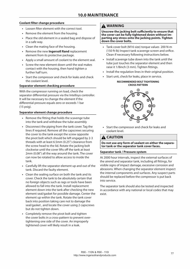
R90 - 110N & R90 - 110Ihttp://www.ingersollrandproducts.com
��
10.0 MAINTENANCE
Coolant filter change procedure
Loosen filter element with the correct tool.Remove the element from the housing.Place the old element in a sealed bag and dispose of in a safe way.Clean the mating face of the housing.Remove the new Ingersoll Rand replacement element from its protective package.Apply a small amount of coolant to the element seal.Screw the new element down until the seal makes contact with the housing, then hand tighten a further half turn.Start the compressor and check for leaks and check the coolant level.
Separator element checking procedure
With the compressor running on load, check the separator differential pressure via the Intellisys controller. It will be necessary to change the element if the differential pressure equals zero or exceeds 1 bar (15 psig).
Separator element change procedure
Remove the fitting that holds the scavenge tube into the tank and withdraw the tube assemblyDisconnect the piping from the tank cover. Tag the lines if required. Remove all the capscrews securing the cover to the tank except the screw opposite the pivot bolt which should be left engaged by 2-3 threads with at least 6.5mm (0.25”) clearance from the screw head to the lid. Rotate the jacking bolt clockwise until the cover lifts off the tank at least 2mm (0.08”) all the way around the tank. The cover can now be rotated to allow access to inside the tank.Carefully lift the separator element up and out of the tank. Discard the faulty element.Clean the sealing surface on both the tank and its cover. Check the tank to be absolutely certain that no foreign objects such as rags or tools have been allowed to fall into the tank. Install replacement element down into the tank after checking the new element seal/gasket for possible damage. Center the element up within the tank. Rotate the tank cover back into position taking care not to damage the seal/gasket , and locate the cover using 2 capscrews but do not tighten down.Completely remove the pivot bolt and tighten the cover bolts in a cross-pattern to prevent over-tightening one side of the cover. An improperly tightened cover will likely result in a leak.
•••
••
••
•
•
•
•
•
•
WARNINGUnscrew the jacking bolt sufficiently to ensure that the cover can be fully tightened down without im-parting any stress onto the jacking points. Tighten down the cover bolts.
Tank cover bolt (M16 size) torque values 200 N-m (150 ft-lb) Inspect tank scavenge screen and orifice. Clean if necessary following instructions below.Install scavenge tube down into the tank until the tube just touches the separator element and then raise it 1/8inch (3 mm). Tighten fittings.Install the regulation lines in their original position.Start unit, check for leaks, place in service.
RECOMMENDED BOLT TIGHTENING CROSS PATTERN
Start the compressor and check for leaks and coolant level.
CAUTIONDo not use any form of sealant on either the separa-tor tank or the separator tank cover faces.
Separator tank / Pressure system
At 2000 hour intervals, inspect the external surfaces of the airend and separator tank, including all fittings, for visible signs of impact damage, excessive corrosion and abrasions. When changing the separator element inspect the internal components and surfaces. Any suspect parts should be replaced before the compressor is put back into service.
The separator tank should also be tested and inspected in accordance with any national or local codes that may exist.
•
•
••
•
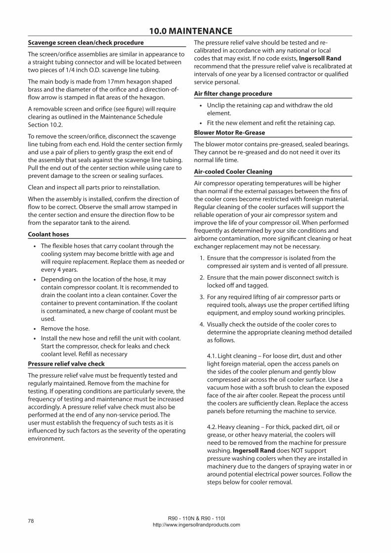
R90 - 110N & R90 - 110Ihttp://www.ingersollrandproducts.com
��
10.0 MAINTENANCEScavenge screen clean/check procedure
The screen/orifice assemblies are similar in appearance to a straight tubing connector and will be located between two pieces of 1/4 inch O.D. scavenge line tubing.
The main body is made from 17mm hexagon shaped brass and the diameter of the orifice and a direction-of-flow arrow is stamped in flat areas of the hexagon.
A removable screen and orifice (see figure) will require clearing as outlined in the Maintenance Schedule Section 10.2.
To remove the screen/orifice, disconnect the scavenge line tubing from each end. Hold the center section firmly and use a pair of pliers to gently grasp the exit end of the assembly that seals against the scavenge line tubing. Pull the end out of the center section while using care to prevent damage to the screen or sealing surfaces.
Clean and inspect all parts prior to reinstallation.
When the assembly is installed, confirm the direction of flow to be correct. Observe the small arrow stamped in the center section and ensure the direction flow to be from the separator tank to the airend.
Coolant hoses
The flexible hoses that carry coolant through the cooling system may become brittle with age and will require replacement. Replace them as needed or every 4 years.Depending on the location of the hose, it may contain compressor coolant. It is recommended to drain the coolant into a clean container. Cover the container to prevent contamination. If the coolant is contaminated, a new charge of coolant must be used.Remove the hose.Install the new hose and refill the unit with coolant. Start the compressor, check for leaks and check coolant level. Refill as necessary
Pressure relief valve check
The pressure relief valve must be frequently tested and regularly maintained. Remove from the machine for testing. If operating conditions are particularly severe, the frequency of testing and maintenance must be increased accordingly. A pressure relief valve check must also be performed at the end of any non-service period. The user must establish the frequency of such tests as it is influenced by such factors as the severity of the operating environment.
•
•
••
The pressure relief valve should be tested and re-calibrated in accordance with any national or local codes that may exist. If no code exists, Ingersoll Rand recommend that the pressure relief valve is recalibrated at intervals of one year by a licensed contractor or qualified service personal.
Air filter change procedure
Unclip the retaining cap and withdraw the old element.Fit the new element and refit the retaining cap.
Blower Motor Re-Grease
The blower motor contains pre-greased, sealed bearings. They cannot be re-greased and do not need it over its normal life time.
Air-cooled Cooler Cleaning
Air compressor operating temperatures will be higher than normal if the external passages between the fins of the cooler cores become restricted with foreign material. Regular cleaning of the cooler surfaces will support the reliable operation of your air compressor system and improve the life of your compressor oil. When performed frequently as determined by your site conditions and airborne contamination, more significant cleaning or heat exchanger replacement may not be necessary.
Ensure that the compressor is isolated from the compressed air system and is vented of all pressure.
Ensure that the main power disconnect switch is locked off and tagged.
For any required lifting of air compressor parts or required tools, always use the proper certified lifting equipment, and employ sound working principles.
Visually check the outside of the cooler cores to determine the appropriate cleaning method detailed as follows. 4.1. Light cleaning – For loose dirt, dust and other light foreign material, open the access panels on the sides of the cooler plenum and gently blow compressed air across the oil cooler surface. Use a vacuum hose with a soft brush to clean the exposed face of the air after cooler. Repeat the process until the coolers are sufficiently clean. Replace the access panels before returning the machine to service. 4.2. Heavy cleaning – For thick, packed dirt, oil or grease, or other heavy material, the coolers will need to be removed from the machine for pressure washing. Ingersoll Rand does NOT support pressure washing coolers when they are installed in machinery due to the dangers of spraying water in or around potential electrical power sources. Follow the steps below for cooler removal.
•
•
1.
2.
3.
4.

R90 - 110N & R90 - 110Ihttp://www.ingersollrandproducts.com
�9
10.0 MAINTENANCEAir-cooled Cooler Removal
Ensure that the compressor is isolated from the compressed air system and is vented of all pressure.
Ensure that the main power disconnect switch is locked off and tagged.
For any required lifting of air compressor parts or required tools, always use the proper certified lifting equipment, and employ sound working principles.
Drain the oil from the oil cooler by removing the M22 hex plug located at the front of the air compressor, and lower side of the oil cooler.
Remove all hoses, pipes, and sensors from the coolers.
Remove the access panels on the sides of the cooler plenum
Properly secure the air aftercooler and remove the (4) nuts from the (2) bolts at the upper sides of the cooler.
Remove the (2) nuts from the bolts at the bottom of the cooler.
Carefully remove the air aftercooler.
Properly secure the oil cooler and remove the (4) nuts from the (2) bolts at the upper sides of the cooler.
Remove the (2) nuts from the bolts at the bottom of the cooler.
Carefully remove the oil cooler.
Re-install the M22 oil drain plug to 65 N-m (48 Ft-Lbs).
WARNINGStrong cleaners can harm aluminum coolers and associated parts. Use the appropriate cleaners for aluminum, and follow the manufacturer’s instructions closely. Always wear the appropriate safety equipment.
Air-cooled Cooler Installation
Ensure that the compressor is isolated from the compressed air system and is vented of all pressure.
Ensure that the main power disconnect switch is locked off and tagged.
For any required lifting of air compressor parts or required tools, always use the proper certified lifting equipment, and employ sound working principles.
Carefully place the oil cooler in its proper location and install the (2) sets of lower fasteners, tightly.
Install the (2) sets of upper side fasteners, finger tight + ¼ turn. Next add the second nut to each tightly. This second nut is used to lock the first in place. It is
1.
2.
3.
4.
5.
6.
7.
8.
9.
10.
11.
12.
13.
1.
2.
3.
4.
5.
important the first nut is not too tight so it can allow the cooler to expand and contract without stressing the cooler’s brazed joints.
Ensure the rubber seal on the air aftercooler is in place on the cooler and in good condition.
Carefully place the air aftercooler cooler in its proper location and install the (2) sets of lower fasteners, tightly.
Install the (2) sets of upper side fasteners, finger tight + ¼ turn. Next add the second nut to each tightly. This second nut is used to lock the first in place. It is important the first nut is not too tight so it can allow the cooler to expand and contract without stressing the cooler’s brazed joints.
Re-attach all hoses, pipes and sensors, and properly torque according to the table shown…
Replace the access panels on the sides of the cooler plenum.
Refill the machine with oil to the proper level.
Water-cooled Cooler Cleaning (for both Clean & Harsh Water Options)
A periodic inspection and maintenance program should be implemented for water cooled heat exchangers. It is recommended that you contact Ingersoll Rand for cleaning services should you not have experience and equipment to do this work. Pre-Inspection:
If water inlet lines have strainers, inspect them and replace or clean as required.
Cleaning:
Mineral scale may be removed with a suitable de-scaling agent containing amidosulphuric acid + citric acid and Neutralit solutions for cleaning the coolers. As an alternative, any weak acid mixed with water in the ratio of 1:4 may be used.Fouling should be removed with a suitable detergent in hot water.Back flush the cooler with a flow rate at least 1.5 times the normal flow rate.After using any cleaning solution, thoroughly flush out all chemicals with clean water before returning the cooler to service. Mechanical cleaning methods are not recommended as damage to the internal passages may occur.
Post-Cleaning Inspection:
Examine the cooler for erosion or corrosion.Airend bearings
Airend bearings are lubricated by the compressor coolant and require no maintenance.
6.
7.
8.
9.
10.
11.
•
•
•
•
•
•
•

R90 - 110N & R90 - 110Ihttp://www.ingersollrandproducts.com
�0
10.0 MAINTENANCEHigh Airend Temperature Sensor checking procedure
It is recommended that the discharge temperature sensor (2ATT) is checked regularly as follows:
Aircooled machines Stop the cooling blower by opening the blower / fan mo-tor circuit breaker.
Watercooled machines Shut off the cooling water.
The machine should trip at 109° C (228° F).
CAUTIONUnder no circumstances should these discharge temperatures be exceeded. If the machine fails to trip A FAULT EXISTS. Investigate immediately.
Motor cowl cleaning
Ensure compressor is electrically isolated for at least 15 minutes before commencing any maintenance work.Remove panels from the compressor.Using a clean dry cloth, remove dust from the surface of the motor cowl and ensure all ventilation slots are free of obstructions.Replace panels to the compressor.
Drive Box Filter Removal / Replacement (For VSD only)
Ensure compressor is electrically isolated for at least 15 minutes before commencing any maintenance work.Unclip the front grill of the drive box filter.Remove the filter pad from the housing and replace with a new filter pad from Ingersoll Rand.Replace front grill to the drive box filter.
Moisture Separator Check / Cleaning
Ensure compressor is electrically isolated for at least 15 minutes, before commencing any maintenance work.Isolate the compressor from the system and fully discharge the compressed air within the unit.Remove tube from the fitting located on the bottom of the moisture separator.Remove the bowl of the moisture trap, clean and replace.
Package Pre-Filter (is washable with mild detergent)
To remove Pre-Filter element:-
Unlatch the two 1/4 turn latches and open intake panel (panel is hinged)Remove the Six (6) wing nutsRemove filter grillPull out filter element
•
••
•
•
••
•
•
•
•
•
•
•••
To Install Pre-Filter element:-
Center element over package intake openingPush filter over grill studs so that studs poke through the filter mediaInstall filter grillInstall Six (6) wing nutsClose intake panel and latch
No Loss Drain Trap (where fitted) Check / Cleaning
It is recommended to check the no loss drain trap daily to insure that condensate is draining from the moisture seperator system. To check for correct function, press the test button on the unit and listen for condensate / air passing through the drain. If the drain is clogged, replace the no loss drain valve service module. The service module consists of the lower portion of the drain trap and is not servicable.Additionally, it is recommended to replace the service module every 8000 hours or once per year, whichever comes first.
Fluid and Vibration Monitoring
Ingersoll Rand recommends incorporating predictive maintenance, specifically the use of coolant and vibration analysis, into all Preventative Maintenance programs. Predictive Maintenance is designed to increase system reliability and prevent costly downtime. Through the use of sophisticated diagnostic tools, including fluid, vibration, and optional air analysis, Ingersoll Rand Certified Service Technicians can identify and correct potential problems BEFORE they can cause expensive unscheduled downtime.
How does predictive analysis work? By establishing an initial baseline for normal operation, and then regularly monitoring fluid and vibration conditions, any sudden deviation or significant increase from this baseline can be identified and investigated to pinpoint the cause. More quickly diagnosing potential problems can directly save money by preventing costly failures and reducing or eliminating downtime. In addition, regular condition monitoring also helps to maximize the time between expensive preventative maintenance intervals, such as component rebuilds and coolant changes.
••
•••
•
•
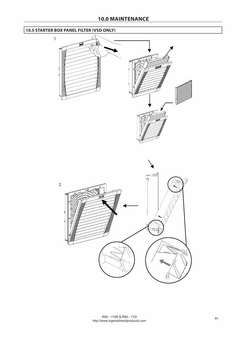
R90 - 110N & R90 - 110Ihttp://www.ingersollrandproducts.com
�1
10.0 MAINTENANCE
10.5 STARTER BOX PANEL FILTER (VSD ONLY)
PULL
1
2
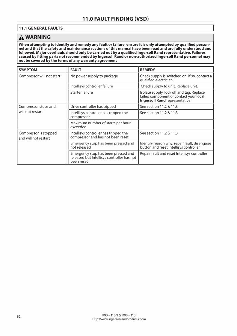
R90 - 110N & R90 - 110IHttp://www.ingersollrandproducts.com
��
11.0 FAULT FINDING (VSD)
11.1 GENERAL FAULTS
WARNINGWhen attempting to identify and remedy any fault or failure, ensure it is only attempted by qualified person-nel and that the safety and maintenance sections of this manual have been read and are fully understood and followed. Major overhauls should only be carried out by a qualified Ingersoll Rand representative. Failures caused by fitting parts not recommended by Ingersoll Rand or non-authorized Ingersoll Rand personnel may not be covered by the terms of any warranty agreement
SYMPTOM FAULT REMEDY
Compressor will not start No power supply to package Check supply is switched on. If so, contact a qualified electrician.
Intellisys controller failure Check supply to unit. Replace unit.
Starter failure Isolate supply, lock off and tag. Replace failed component or contact your local Ingersoll Rand representative
Compressor stops and will not restart
Drive controller has tripped See section 11.2 & 11.3
Intellisys controller has tripped the compressor
See section 11.2 & 11.3
Maximum number of starts per hour exceeded
Compressor is stopped and will not restart
Intellisys controller has tripped the compressor and has not been reset
See section 11.2 & 11.3
Emergency stop has been pressed and not released
Identify reason why, repair fault, disengage button and reset Intellisys controller
Emergency stop has been pressed and released but Intellisys controller has not been reset
Repair fault and reset Intellisys controller
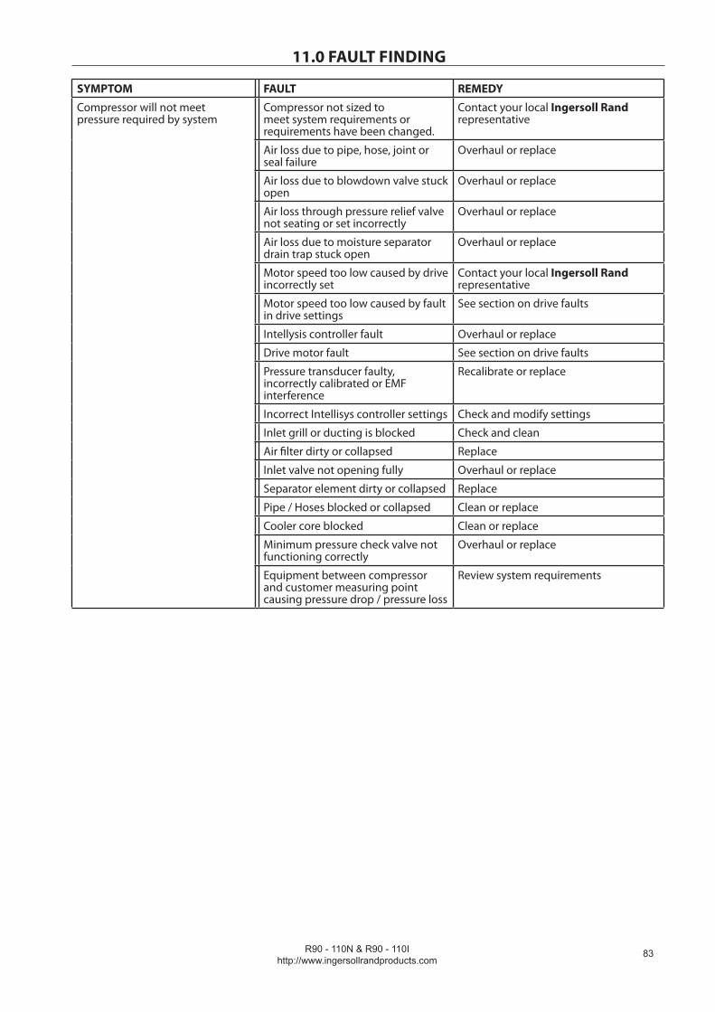
R90 - 110N & R90 - 110Ihttp://www.ingersollrandproducts.com
��
11.0 FAULT FINDING
SYMPTOM FAULT REMEDY
Compressor will not meet pressure required by system
Compressor not sized to meet system requirements or requirements have been changed.
Contact your local Ingersoll Rand representative
Air loss due to pipe, hose, joint or seal failure
Overhaul or replace
Air loss due to blowdown valve stuck open
Overhaul or replace
Air loss through pressure relief valve not seating or set incorrectly
Overhaul or replace
Air loss due to moisture separator drain trap stuck open
Overhaul or replace
Motor speed too low caused by drive incorrectly set
Contact your local Ingersoll Rand representative
Motor speed too low caused by fault in drive settings
See section on drive faults
Intellysis controller fault Overhaul or replace
Drive motor fault See section on drive faults
Pressure transducer faulty, incorrectly calibrated or EMF interference
Recalibrate or replace
Incorrect Intellisys controller settings Check and modify settings
Inlet grill or ducting is blocked Check and clean
Air filter dirty or collapsed Replace
Inlet valve not opening fully Overhaul or replace
Separator element dirty or collapsed Replace
Pipe / Hoses blocked or collapsed Clean or replace
Cooler core blocked Clean or replace
Minimum pressure check valve not functioning correctly
Overhaul or replace
Equipment between compressor and customer measuring point causing pressure drop / pressure loss
Review system requirements

R90 - 110N & R90 - 110IHttp://www.ingersollrandproducts.com
��
11.0 FAULT FINDINGSYMPTOM FAULT REMEDY
Pressure produced by compressor is too high compressor is too high due to speed not reducing as demand reduces
Intellisys set incorrectly Check and modify settings
Pressure transducer may be faulty, incorrectly calibrated or not receiving pressure signal
Recalibrate or replace
Drive settings fault Contact your local Ingersoll Rand representative
Compressor discharge air too hot
High ambient temperature Review installation and system parameters
Insufficient cooling air Check ducting and cooling air path, check direction of blower rotation
Dirty, blocked aftercooler (cooling air side)
Clean or replace
Compressor package produces excessive noise
Panels or doors are not closed properly
Rectify fault
Air leaks from internal pipework / components
Overhaul or replace
Blower or blower motor bearings worn
Overhaul or replace
Loose debris impacting on blower during rotation
Remove and rectify any damage
Blowdown valve stuck open Overhaul or replace
Pressure relief valve not seating correctly
Overhaul or replace
Vibration due to motor, airend or blower imbalance
Overhaul or replace
Airend requires overhaul Contact your local Ingersoll Rand representative
Discharge air is contaminated with coolant
Scavenge pipe is blocked, broken or o-ring is not sealing
Clean or replace
Separator element is punctured, or incorrect, or requires changing, or not sealing correctly
Replace
Incorrect coolant has been added Drain system, check for damage. Clean, refill with correct coolant.
System has been overfilled with coolant
Check for damage, drain excess.
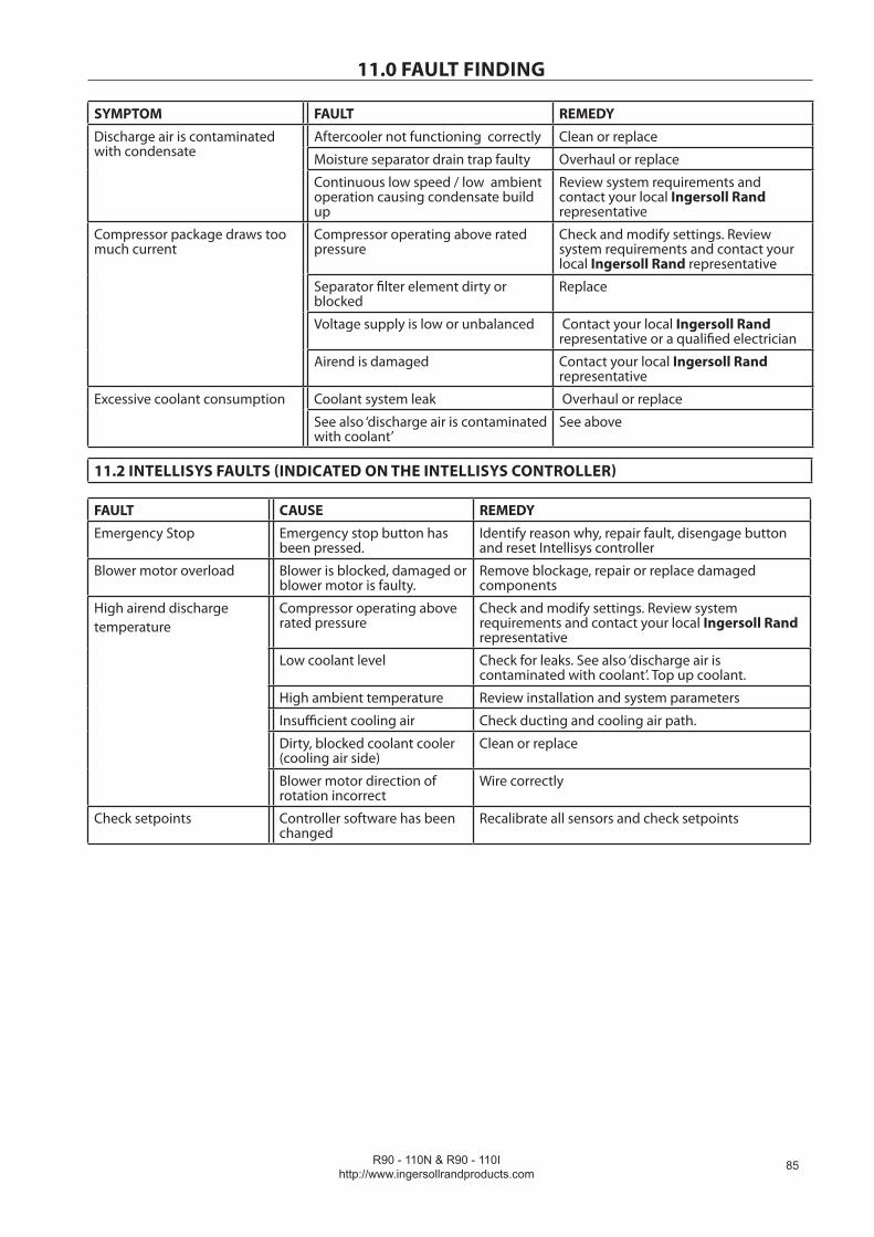
R90 - 110N & R90 - 110Ihttp://www.ingersollrandproducts.com
��
11.0 FAULT FINDING
SYMPTOM FAULT REMEDY
Discharge air is contaminated with condensate
Aftercooler not functioning correctly Clean or replace
Moisture separator drain trap faulty Overhaul or replace
Continuous low speed / low ambient operation causing condensate build up
Review system requirements and contact your local Ingersoll Rand representative
Compressor package draws too much current
Compressor operating above rated pressure
Check and modify settings. Review system requirements and contact your local Ingersoll Rand representative
Separator filter element dirty or blocked
Replace
Voltage supply is low or unbalanced Contact your local Ingersoll Rand representative or a qualified electrician
Airend is damaged Contact your local Ingersoll Rand representative
Excessive coolant consumption Coolant system leak Overhaul or replace
See also ‘discharge air is contaminated with coolant’
See above
11.2 INTELLISYS FAULTS (INDICATED ON THE INTELLISYS CONTROLLER)
FAULT CAUSE REMEDY
Emergency Stop Emergency stop button has been pressed.
Identify reason why, repair fault, disengage button and reset Intellisys controller
Blower motor overload Blower is blocked, damaged or blower motor is faulty.
Remove blockage, repair or replace damaged components
High airend dischargetemperature
Compressor operating above rated pressure
Check and modify settings. Review system requirements and contact your local Ingersoll Rand representative
Low coolant level Check for leaks. See also ‘discharge air is contaminated with coolant’. Top up coolant.
High ambient temperature Review installation and system parameters
Insufficient cooling air Check ducting and cooling air path.
Dirty, blocked coolant cooler (cooling air side)
Clean or replace
Blower motor direction of rotation incorrect
Wire correctly
Check setpoints Controller software has been changed
Recalibrate all sensors and check setpoints

R90 - 110N & R90 - 110IHttp://www.ingersollrandproducts.com
��
11.0 FAULT FINDING
FAULT CAUSE REMEDY
Remote start failure Remote start button is pressed after machine is running or remote start button remains closed.
Check operation of buttons or operating procedures
Remote stop failure Remote stop button remains open and either start button is pressed
Check operation of buttons or operating procedures
Sensor failure Sensor is missing or faulty Install, repair or replace faulty sensor
Compressor trips indicating a high compressor temperature.
Insufficient cooling taking place If machine is watercooled or sea watercooled, check that the cooling water is flowing. Check that there is no air in the water cooling system. Check that the strainer is not blocked.
Intellisys controller has tripped the compressor
A fault has occurred Repair fault / reset Intellisys controller
Invalid Calibration Calibration done with pressure in compressor.
Depressurise and re calibrate with pressure pipe to sensor disconnected. If fault still exists, replace pressure transducer.
Low sump pressure System leak Located and repair
Minimum pressure check valve faulty
Repair with service kit
Blowdown valve faulty Repair with service kit
Loss of control power Check 110V circuit breaker Check wiring Check contactor KM1
Check motor rotation Drive system fault Contact your local Ingersoll Rand representative
VSD communication failure Communication wiring faulty Check and replace if required
Drive faulty Contact your local Ingersoll Rand representative
Intellisys faulty Contact your local Ingersoll Rand representative
VSD initialisation fault Communication wiring faulty Check and replace if required
Drive faulty Contact your local Ingersoll Rand representative
Intellisys faulty Contact your local Ingersoll Rand representative
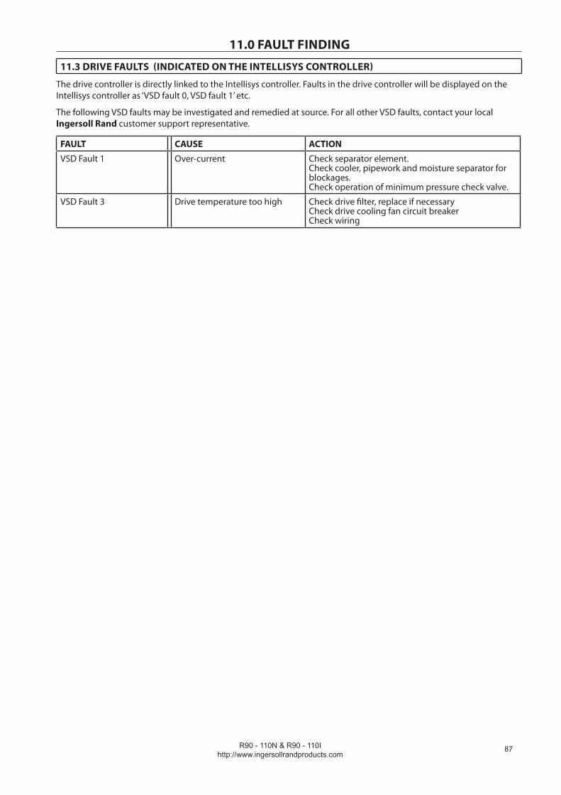
R90 - 110N & R90 - 110Ihttp://www.ingersollrandproducts.com
��
11.0 FAULT FINDING
11.3 DRIVE FAULTS (INDICATED ON THE INTELLISYS CONTROLLER)
The drive controller is directly linked to the Intellisys controller. Faults in the drive controller will be displayed on the Intellisys controller as ‘VSD fault 0, VSD fault 1’ etc.
The following VSD faults may be investigated and remedied at source. For all other VSD faults, contact your local Ingersoll Rand customer support representative.
FAULT CAUSE ACTION
VSD Fault 1 Over-current Check separator element. Check cooler, pipework and moisture separator for blockages. Check operation of minimum pressure check valve.
VSD Fault 3 Drive temperature too high Check drive filter, replace if necessary Check drive cooling fan circuit breaker Check wiring
Related Documents