INSTRUCTION MANUAL FOR INSTALLING OPERATING and MAINTAINING the 9-Inch Stroke PET STAR 4 COMPRESSOR © Ingersoll-Rand Company 2004 Printed in U.S.A.

Welcome message from author
This document is posted to help you gain knowledge. Please leave a comment to let me know what you think about it! Share it to your friends and learn new things together.
Transcript

INSTRUCTION MANUAL
FOR
INSTALLING
OPERATING and
MAINTAINING
the 9-Inch Stroke
PET STAR 4COMPRESSOR
© Ingersoll-Rand Company 2004 Printed in U.S.A.
Front Matter 80441579 Rev. A (PS - 4)
ii
PREFACEDetailed instructions for installing, operating and maintaining the Ingersoll-Rand Model
PET Star 4 compressor are contained in this manual. This manual is intended to cover manyof the basic points of installing, operating and servicing of the compressor, and to supplementthe experience and mechanical ability of a competent engineer. If there are any points notclearly covered, please contact your nearest Ingersoll-Rand office. We have a continuedinterest in the operation of our equipment. We wish to build and stand by every unit so that thepurchase of this compressor will always be considered a wise investment.
Ingersoll-Rand welcomes inquiries regarding any phase of compressor practice,installation, operation, and repairs or changes to meet unexpected conditions. Our salesdepartment and local representatives will confer with you on any prospective installation orchange. Call or write our local offices for information and advice on any point.
A preventive inspection and maintenance schedule will help to ensure optimumperformance of the unit, while avoiding possible difficulties at some inconvenient time.
We stock standard replacement parts at strategically located parts warehouses. Ifneeded, crisis orders can be processed immediately.
Ingersoll-Rand Field Service Technical Representatives, skilled in compressor work, areavailable for installation, inspection or repair. Contact the Ingersoll-Rand Customer SolutionsCenter to request these services. They will be glad to supply you with current rates for theseservices.
Proper installation and operation of the compressor is extremely important. Thesuccess of a unit frequently depends on how it is installed. We strongly urge that such work besupervised by our Field Service Technical Representatives, who are thoroughly familiar withconstruction design and techniques, and who can also instruct your personnel in the operationand maintenance of the equipment.
Many of our customers, especially those operating several units, have our Field ServiceTechnical Representatives make periodic inspections to prevent malfunctions and to ensure thebest possible operating results. Our representatives can explain how to operate Ingersoll-Randunits to achieve the greatest efficiency and economy, while obtaining the longest possibleequipment life. When sending for a Field Service Technical Representative to make repairs,be sure to give the compressor serial number with full details as to what is wrong and what newparts are, or may be, needed. To ensure quick turnaround, have these parts on hand.

80441579 Rev. A (PS - 4) Front Matter
iii
CONTENTS
SAFETY INFORMATION
EQUIPMENT DESCRIPTION .............................CHAPTER 1
INSTALLATION..................................................CHAPTER 2
OPERATION AND TROUBLESHOOTING.........CHAPTER 3
MAINTENANCE..................................................CHAPTER 4
GENERAL DATA AND CLEARANCES.............CHAPTER 5

Front Matter 80441579 Rev. A (PS - 4)
iv
SAFETY PRECAUTIONSSafety Information
WARNINGDO NOT OPERATE THIS EQUIPMENT IN EXCESS OF ITS RATEDCAPACITY, SPEED, PRESSURE AND TEMPERATURE, NOROTHERWISE THAN IN ACCORDANCE WITH THE INSTRUCTIONSCONTAINED IN THIS SERVICE MANUAL. OPERATION OF THEEQUIPMENT IN EXCESS OF THE CONDITIONS SET FORTH IN THESALES CONTRACT WILL SUBJECT IT TO STRESSES ANDSTRAINS THAT IT WAS NOT DESIGNED TO WITHSTAND. FAILURETO HEED THIS WARNING MAY RESULT IN AN ACCIDENT CAUSINGPERSONAL INJURY OR PROPERTY DAMAGE.
WARNINGREAD CAREFULLY AND UNDERSTAND THIS SERVICE MANUAL
BEFORE INSTALLING OR OPERATING THE COMPRESSOR.
This service manual contains important instructions and information on the installation,operation and maintenance of Ingersoll-Rand Model PET Star 4 compressors. THEIMPORTANCE OF GETTING THIS SERVICE MANUAL INTO THE HANDS OF THEPERSON IN CHARGE OF INSTALLING THE COMPRESSOR CANNOT BEOVEREMPHASIZED. All personnel involved in the installation, operation andmaintenance of the compressor should have access to this service manual and befamiliar with its contents. Strict adherence to these instructions will be repaid by satisfac-tory compressor performance and acceptable upkeep costs.
Do not remove the stainless steel nameplates that are attached to the machine. Theseplates give serial numbers that are necessary when communicating with Ingersoll-Randabout the equipment. Also, do not remove safety labels. If these labels are removed ordefaced, new ones should be obtained from Ingersoll-Rand Company.
REFER ALL COMMUNICATIONS TO THE NEAREST INGERSOLL-RAND COMPANYOFFICE.

80441579 Rev. A (PS - 4) Front Matter
v
Dangers, warnings and cautions appearing throughout this service manual are ofparamount importance to personnel and equipment safety. Prior to any attempt to operate,maintain, troubleshoot, or repair any part of the compressor, all DANGERS, WARNINGS andCAUTIONS should be thoroughly reviewed and understood. Refer to the Safety Summary thatstarts on the next page. The information immediately following defines "signal words" as theyare used in this manual.
SIGNAL WORDS ARE USED TO IDENTIFY LEVELS OF HAZARD SERIOUSNESS. THEIRSELECTION IS BASED ON THE LIKELY CONSEQUENCE OF HUMAN INTERACTION WITHTHE HAZARD IN TERMS OF:
● DEGREE OF SEVERITY (minor injury, severe injury, death)
● THE PROBABILITY OF SEVERITY (will result, could result)
DANGERThe word DANGER signifies immediate hazards that WILL result in severepersonal injury or death. In the service manual, this should be construedto be a VERY STRONG Warning (see below).
WARNINGThe word WARNING refers to hazards or unsafe practices that COULDresult in severe personal injury or death. This is found quite often in theservice manual due to its association with unsafe practices.
CAUTIONThe word CAUTION refers to hazards or unsafe practices that COULDresult in minor personal injury, or product or property damage. This wordis found frequently in the service manual due to the fact that bad mainte-nance practices or procedures can so often result in damage to the com-pressor. Because what constitutes a "minor" injury is open to debate, wehave upgraded many CAUTIONS to WARNING.
NOTE
NOTES are used to highlight certain operating or maintenance conditions orstatements that are essential but not of a known hazardous nature, as would beindicated by DANGER, WARNING or CAUTION.
Front Matter 80441579 Rev. A (PS - 4)
vi
SAFETY SUMMARY
The following safety precautions are being recommended only in regard to thecompressor and other Ingersoll-Rand supplied equipment (ex: motors, consoles, etc.). Abideby all OSHA and all other applicable safety regulations, including all site-specific safety andwork procedures.
The installation, operation and maintenance of a compressor and auxiliary componentsmay present certain hazards that are unique to this type of equipment. The following list ofsafety precautions must be thoroughly read and reviewed by all personnel prior to working withor on the compressor equipment and systems. These general statements are expanded uponin the sections of the manual appropriate to their application. Failure to heed thesestatements can result in an incident causing property damage, personal injury or death.
● All electrical motor and control wiring must be carefully installed in accordance with theNational Electric Code, the Occupational Safety and Health Act of 1970 (OSHA) andany other code requirements at the installation site.
● Piping subject to temperatures in excess of 175ºF (80ºC) which may be touched bypersonnel must be suitably guarded or insulated.
● It is imperative that all gases lighter or heavier than air, active or inactive, toxic,combustible, obnoxious, objectionable, or in any way harmful to personnel orequipment, be piped away from the compressor. There must be no manifolding of venttubing or piping; nor can back pressure be allowed to develop in any vent line. Gasesmay be re-circulated as required by the process, but in any case must be controlledand/or disposed of in accordance with OSHA regulations and local pollution laws.
• The compressor must be fitted with pressure relief valves or rupture disks to limit thedischarge pressures to a safe maximum. NEVER install an intervening valve betweena compressor cylinder and the pressure relief valve or rupture disk.
● Pressure relief valves must have their settings tested at least once a year, and moreoften under extreme operating conditions, using an appropriate bench test.
● If a pressure relief valve or rupture disk blows during operation, stop the unitimmediately and determine the cause.
● Pressure relieving devices that are vented to the atmosphere must have their outletconnections directed away from operator stations.
● Rotating equipment must not be placed in operation unless adequate safeguards havebeen provided to protect operating personnel.
● Service on a machine shall always start with cleaning the floor and the outside of themachinery to remove oil that could cause maintenance personnel to slip.
● Whenever a compressor is shut down for repairs, positive steps must be taken toprevent the prime mover from being inadvertently energized and started. Equipmentbeing worked on should be “Locked Out” and “Tagged Out” to ensure againstinadvertently providing power and accidentally starting. In addition, a warning signbearing the legend "WORK IN PROGRESS-DO NOT START", or similar wording, shallbe attached to the starting equipment.

80441579 Rev. A (PS - 4) Front Matter
vii
● Whenever the compressor is shut down because overheating is suspected, a minimumperiod of 30 minutes must elapse before the crankcase is opened. Premature openingof the crankcase can result in a crankcase explosion.
● Prior to opening the compressor, or undertaking a major overhaul, the unit must bepositively blocked against rollover and movement of the running gear. When the unitis equipped with a flywheel locking/v-sheave device, this device must be used to preventrollover. Blocking of the crankshaft or crossheads is an alternate method of preventingaccidental rollover.
● Never open a compressor cylinder or any other part of the compression system withoutfirst completely relieving all pressure within the compressor cylinders, piping, vesselsand coolers; and taking all necessary precautions to prevent accidental pressurizing ofthe system.
● Incorrect placement of the inlet and discharge valves in the cylinders can cause an ex-tremely hazardous condition. INSTALLING AN INLET VALVE IN A DISCHARGEVALVE PORT, OR INSTALLING A DISCHARGE VALVE UPSIDE DOWN, MAY CAUSEEXCESSIVE PRESSURE IN THE CYLINDER RESULTING IN RUPTURE AND/OR ANEXPLOSION.
● Discharge valve ports usually are made slightly smaller at the minor diameter below thevalve gasket seat; this is called "polarization". When an inlet valve is installed in adischarge port by mistake, it will not fit down into the port properly and the mechanic willbe alerted to the error.
● In many cases, the inlet valve stop plates have lugs that will prevent an inlet valve frombeing installed in a discharge valve port by mistake; this is another type of "polarization".The minor diameter of the discharge port is slightly smaller so the inlet valve will not fitproperly, alerting the mechanic to the error.
● If IN DOUBT as to whether a valve is inlet or discharge, or as to which cylinder valveports receive inlet or discharge valves, CHECK WITH YOUR SUPERVISOR.
● Corrective action must be taken when the piston rod pressure packing vent leakage isexcessive, or when there is a sudden increase in the leakage rate.
● After any maintenance or overhaul of the compressor, the unit must be barred throughat least one complete revolution to ensure that there are no mechanical obstructionswithin the machine.
● A manual bar and fulcrum and/or a hydraulic or pneumatic barring rig may have beenprovided as a means of rotating the compressor crankshaft during installation, duringmaintenance, prior to start-up after maintenance or overhaul, and at any other timeexact positioning of the running gear is required. Compressor cylinders must bedepressurized to atmospheric pressure before barring. Compressor pistons will moveto crank end dead center as an equilibrium condition due to the difference in crank endand head end piston surface areas if exposed to the system air pressure. Failure todepressurize the compressor cylinders prior to barring may result in unexpected rotationthat can cause personal injury.
● Established operating and maintenance procedures, as well as basic safety precautions,must be reviewed with the operating and maintenance personnel at regular intervals,

Front Matter 80441579 Rev. A (PS - 4)
viii
not to exceed six months. Newly assigned operators must be thoroughly trained in thesafe operation of this equipment before they are permitted to operate it.
● Whenever an outer head is removed from the compressor cylinder, make certain thatthe piston vent hole(s), if used, located in the outer face of the piston are open and thatthe piston does not contain pressure.
● Never use an air impact wrench for ANY tightening of critical fasteners. An impactwrench cannot accurately impart the proper bolt or stud pre-stress. See CHAPTER 5of this manual for detailed fastener tightening requirements and procedures.
● Special attention should be paid to all detailed DANGER, WARNING and CAUTIONstatements located throughout this manual, and to all SAFETY LABELS affixed to theequipment.

PET STAR 4CHAPTER 1
EQUIPMENT DESCRIPTION
Paragraph Page
1-1. GENERAL INFORMATION .............................................................................. 1-21-1.1. Serial Number ............................................................................................ 1-21-2. DRIVE ARRANGEMENT ................................................................................. 1-31-3. FRAME and RUNNING GEAR ......................................................................... 1-31-3.1. Frame Spacer Bars .................................................................................... 1-31-3.2. Frame Extensions ...................................................................................... 1-31-3.3. Frame oil sump ........................................................................................... 1-71-3.4. Crankshaft .................................................................................................. 1-71-3.5. Connecting Rods ........................................................................................ 1-71-3.6. Crossheads ................................................................................................ 1-81-3.7. Main Bearings ............................................................................................ 1-91-3.8. Connecting Rod & Crosshead Bearings ..................................................... 1-91-4. FRAME LUBRICATION SYSTEM .................................................................... 1-91-4.1. Frame Oil Pump ......................................................................................... 1-111-4.2. Auxiliary Motor-Driven Oil Pump ................................................................ 1-121-4.3. Oil Strainer and Filter ................................................................................. 1-121-4.4. Low Oil Pressure Protection ....................................................................... 1-121-4.5. Frame Breather .......................................................................................... 1-121-5. COMPRESSOR CYLINDERS .......................................................................... 1-121-5.1. Circulated Water cooling ............................................................................. 1-131-5.2. Water Piping ............................................................................................... 1-131-5.3. Compressor Valves .................................................................................... 1-141-5.4. Capacity Control ......................................................................................... 1-141-5.5. Compressor Pistons ................................................................................... 1-141-5.5.1. Piston Rings ......................................................................................... 1-141-5.5.2. Rider Rings ........................................................................................... 1-141-5.6. Piston Rods ................................................................................................ 1-141-5.7. Pressure Packing ....................................................................................... 1-151-5.8. Oil Scraper Rings ....................................................................................... 1-161-6. SAFETY VALVES ............................................................................................ 1-161-7. INTERCOOLERS & AFTERCOOLERS ........................................................... 1-171-8. PRESSURE VESSELS .................................................................................... 1-171-8.1. Pulsation Dampener ................................................................................... 1-171-8.2. Separators .................................................................................................. 1-17

Equipment Description 80441553 Rev. A (PS - 4)
1-2
1-1. GENERAL INFORMATION
This chapter of the Instruction book is intended to familiarize the equipment operatorwith the major components and systems of the Ingersoll-Rand Model PET Star 4compressor. This chapter will help the operator to understand the individual componentsand the relationship of the various compressor parts. Refer to the sub-manufacturer'sliterature (located in the ACCESSORIES section of the job-specific Installation / Operation /Maintenance Manual) for detailed information on accessory equipment used with thecompressor system.
1-1.1. Serial Number
Correspondence concerning your compressor and related equipment must include theequipment serial number. A complete record of serial numbers and other data on yourcompressor is kept at the factory; giving the serial numbers in your correspondence andparts orders helps us in providing prompt service. Figure 1-1 provides a breakdown of theserial numbering system.
• The compressor frame serial number applies to the frame and running gear parts. Itis located on a nameplate which is attached to the side of the frame. It consists ofseveral letters and numbers. Always give the complete serial number (for example,PSN - XXXX).
• Other parts, such as drive motors, control valves, temperature and pressure switchesand piston rod packings, usually have serial numbers or other identification attached,which should be mentioned in any correspondence about these parts.
Figure 1-1. PET Star 4 Serial Numbering System
80441553 Rev. A (PS - 4) Equipment Description
1-3
1-2. DRIVE ARRANGEMENT
The PET Star 4 is normally driven by an induction motor through a V-belt drive andflywheel arrangement. Other drive arrangements, such as a high-speed turbine and gearreducer or a flexible coupling arrangement can be supplied depending on the applicationand requirements.
1-3. FRAME AND RUNNING GEAR
The PET Star 4 compressor frames (Figures 1-1A, B & C) are a "U" type framemade of cast iron with bolt-on frame top covers for easy access to the main and crankpinbearings. These frames have heavily ribbed cross-members supporting the main bearings,which ensure precise bearing alignment. Main bearing saddles are precision bored in asingle setup. The main bearing bore alignment is then confirmed after machining andrecorded.
One additional bearing, located at the drive end of the frame, helps support theadditional loads generated by the V-belt drive. Open frame top construction contains (3)three steel tie rods and individually fitted gray cast iron spacers per pair of compressorthrows. Two of the tie rods are located at the ends of the crank throw bay, one over eachmain bearing. The third tie rod is located in the middle of the crank throw bay. An additionaltie rod and spacer is located over the additional drive end bearing. Gasketed covers, on topof each bay and at the ends of the frame, permit easy access to all the running gearcomponents.
The crankshaft is made of forged steel and all journals are precision ground toexacting tolerances. Oil passages are drilled in the crankshaft to deliver oil to the mainbearings and connecting rod crankpin bearings.
One oil seal is installed around the crankshaft where it extends through the frame atthe drive end. This seal is of the lip type and is normally made of neoprene base material.The seal consists of a split oil slinger ring clamped on the crankshaft along with a lip sealpressed into the frame end cover around the crankshaft.
1-3.1. Frame Spacer Bars
Frame spacer bars and tie rods are used above each main bearing to provide rigidityand prevent distortion of the frame. Spacer bar dimensions are stamped on the frame top toensure the frame is brought back to original specifications when tie rods are retensioned.
1-3.2. Frame Extensions
The frame extensions or crosshead guides are stud-mounted to the frame andsealed with an O-ring as shown in Figure 1-2. O-rings are utilized to prevent oil leakage.Two gasketed solid covers, one per side of both compartments, provide for easymaintenance of the crosshead, oil slinger and oil scrapper assemblies.

Equipment Description 80441553 Rev. A (PS - 4)
1-4
Figure 1-1A. PET Star 4 Frame & Running Gear
Figure 1-1B. PET Star 4 Frame
1.
Fram
e2.
S
tud
3.
Nut
4.
Plu
g5.
C
ap M
ain
Bea
ring
6.
Sho
e Th
rust
7.
Cap
scr
ew8.
S
tud
9.
Nut
10.
Stu
d11
. N
ut C
ap12
. S
pace
r13
. W
ashe
r14
. Tu
be

80441553 Rev. A (PS - 4) Equipment Description
1-5
Figure 1-1C. PET Star 4 Frame
1.
Fram
e2.
C
rank
pin
3.
Cov
er4.
G
aske
t5.
C
over
6.
Gas
ket
7.
Cov
er8.
G
aske
t9.
B
olt
10.
Gau
ge o
il le
vel
11.
Nip
ple
12.
Elb
ow13
. Fi
ller o
il14
. Fl
ange
15.
Gas
ket
16.
Bol
t17
. P
lug
18.
Cov
er19
. G
aske
t20
. C
apsc
rew
21.
Pin
Rol
l22
. S
etsc
rew
23.
Sea
l Cra
nksh
aft
24.
Ret
aine
r25
. S
crew
cap

Equipment Description 80441553 Rev. A (PS - 4)
1-6
Figure 1-2. Frame Extension
1.
Dis
tanc
e pi
ece
2.
Stu
d3.
N
ut4.
P
lug
pipe
5.
Cov
er6.
G
aske
t7.
C
apsc
rew
8.
Foot
pie
ce9.
B
olt
10.
Plu
g pi
pe14
. P
lug
16.
O-ri
ng17
. O
-ring

80441553 Rev. A (PS - 4) Equipment Description
1-7
1-3.3. Frame Oil Sump
The lower part of the frame forms a sump for the lubricating oil. An oil level gauge islocated at the pump end of the frame so the frame oil level can be checked at all times. Theoil is drawn from the sump by either the main shaft-driven oil pump or the auxiliary motor-driven oil pump, and delivered under pressure through an external cooler, filter, then to theoil header and each main bearing.
1-3.4. Crankshaft
The crankshaft (Figure 1-3) is a one-piece forged alloy steel bicycle-type crankshaft,which contains drilled oil passages for pressurized bearing lubrication. A straight-keyedshaft on the drive end allows for easy attachment of the driven sheave utilizing a taperedbushing.
Figure 1-3. Crankshaft
1-3.5. Connecting Rods
The connecting rods (shown in Figure 1-4) are die forged alloy steel with a two piececonstruction. The two pieces are held in position by locating bushings and assembled withtwo high strength capscrews lockwired together to prevent loosening. The neck of the
1. Crankshaft2. Ring crankshaft3. Capscrew4. Dowel pin5. Key square

Equipment Description 80441553 Rev. A (PS - 4)
1-8
connecting rod incorporates a lightweight rifle-drilled I-beam section to allow pressurized oillubrication to the crosshead.
1-connecting rod2-cap bolts3-alignmentbushings4-lockwire5-bearings6-pin bushing
Figure 1-4. Connecting Rod, Crankpin Bearings and Pin Bushing
1-3.6. Crossheads
The standard crosshead (shown in Figure 1-5) is made of cast iron and contains twonon-adjustable aluminum shoes, one each on top and bottom of the crosshead. Thecrosshead pin is a full floating hardened steel cylindrical type and is secured in place bysnap-rings.
1-crosshead2-shoes3-capscrews4-lockwashers5-pin6-cap7-retainers
TP-5048Figure 1-5. Standard Crosshead
80441553 Rev. A (PS - 4) Equipment Description
1-9
1-3.7. Main Bearings
Main bearings consist of top and bottom shells, which fit into machined bores in themain bearing caps and frame (saddles). The shells are held in place by the caps. The mainbearings are precision types (shimless) that are sized to the correct running clearance anddo not require fitting. A micro-babbitt overlay is utilized for start-up protection and longoperating life.
1-3.8. Connecting Rod & Crosshead Bearings
Crankpin and crosshead pin bearings are full floating. Full floating indicates that thebearings are free to rotate on the bearing journal and within the connecting rod or mainbearing housings. No adjustments are ever required. Friction is reduced and bearing wear isevenly distributed around the entire bearing surface, both inside and out.
1-4. FRAME LUBRICATION SYSTEM
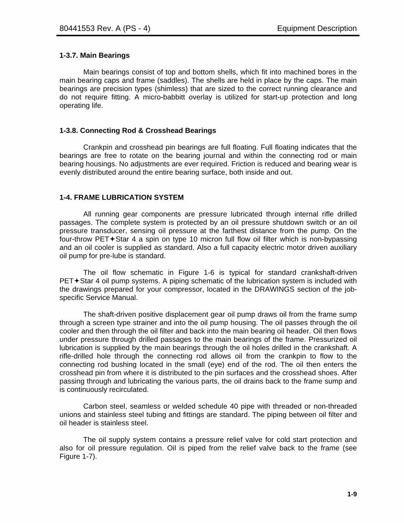
All running gear components are pressure lubricated through internal rifle drilledpassages. The complete system is protected by an oil pressure shutdown switch or an oilpressure transducer, sensing oil pressure at the farthest distance from the pump. On thefour-throw PET Star 4 a spin on type 10 micron full flow oil filter which is non-bypassingand an oil cooler is supplied as standard. Also a full capacity electric motor driven auxiliaryoil pump for pre-lube is standard.
The oil flow schematic in Figure 1-6 is typical for standard crankshaft-drivenPET Star 4 oil pump systems. A piping schematic of the lubrication system is included withthe drawings prepared for your compressor, located in the DRAWINGS section of the job-specific Service Manual.
The shaft-driven positive displacement gear oil pump draws oil from the frame sumpthrough a screen type strainer and into the oil pump housing. The oil passes through the oilcooler and then through the oil filter and back into the main bearing oil header. Oil then flowsunder pressure through drilled passages to the main bearings of the frame. Pressurized oillubrication is supplied by the main bearings through the oil holes drilled in the crankshaft. Arifle-drilled hole through the connecting rod allows oil from the crankpin to flow to theconnecting rod bushing located in the small (eye) end of the rod. The oil then enters thecrosshead pin from where it is distributed to the pin surfaces and the crosshead shoes. Afterpassing through and lubricating the various parts, the oil drains back to the frame sump andis continuously recirculated.
Carbon steel, seamless or welded schedule 40 pipe with threaded or non-threadedunions and stainless steel tubing and fittings are standard. The piping between oil filter andoil header is stainless steel.
The oil supply system contains a pressure relief valve for cold start protection andalso for oil pressure regulation. Oil is piped from the relief valve back to the frame (seeFigure 1-7).

Equipment Description 80441553 Rev. A (PS - 4)
1-10
Figure 1-6. Typical Lubrication System Schematic
Figure 1-7. Relief Valve and Piping

80441553 Rev. A (PS - 4) Equipment Description
1-11
1-4.1. Frame Oil Pump
The frame oil pump is a shaft-driven, gear type pump with two rotating gears, directlydriven off the end of the crankshaft (see Figure 1-8). The four-throw PET Star 4 utilizes thispositive displacement gear pump to serve one crankshaft and running gear.
Figure 1-8. Oil Pump
1.
Ada
pter
Hou
sing
2.
Rin
g E
ccen
tric
3.
Pla
te W
eaer
& S
top
4.
Cov
er O
il P
ump
End
5.
O-r
ing
6.
Sea
l Oil
Pum
p S
haft
7.
Sha
ft M
ain
Oil
Pum
p8.
C
apsc
rew
9.
Thre
adse
al10
. W
ashe
r11
. G
eror
otor
12.
Key
squ
are
13.
Bea
ring
Thru
st14
. C
over
Lub
ricat
or15
. C
apsc
rew
16.
Sea
lant
Gas
ket
17.
Hub
oil
pum
p18
. S
etsc
rew
19.
Key
squ
are

Equipment Description 80441553 Rev. A (PS - 4)
1-12
1-4.2. Auxiliary Motor-Driven Oil Pump
This pump is used as an emergency back-up pump for the main oil pump and as aprelube pump. Controls are arranged for automatic start/stop operation. The pump is locatedon the compressor skid. This type pump normally incorporates a built-in relief valve toprevent excessive discharge pressure.
1-4.3. Oil Strainer and Filter
A wire screen type strainer is installed at the oil pickup end of the pump suction line.The screen protects the oil pump by straining out coarse particles as the oil is drawn fromthe frame sump into the pump suction. The four-throw PET Star 4 utilizes two oil strainers.
The standard oil filter for the four-throw PET Star 4 is a 10 micron full flow type thatis non-bypassing. The filter is a spin on type where the filter elements have a collapse ratingof 100psi-pressure differential.
1-4.4. Low Oil Pressure Protection
The PET Star 4 compressor is equipped with an automatic safety shutdownswitch/pressure transducer which monitors the oil pressure at the drive end main bearingand initiates unit shutdown when the oil pressure reaches the setpoint. An oil pressuregauge is piped to the shutdown switch to indicate the pressure at the switch or it can bemonitored on the control panel.
1-4.5. Frame Breather
The frame breather is mounted on the side of the frame. It vents the non-condensingoil vapors from the frame interior to atmosphere while returning the condensed oil to theframe sump. It also serves as an oil filler by removing the breather cap and pouring oilthrough the breather tube.
1-5. COMPRESSOR CYLINDERS
Compressor cylinders are designed and constructed to compress air from a lower(inlet) to a higher (discharge) pressure. Depending on the application, the cylinders can bemade of either cast iron, nodular iron, steel, or forged steel. The standard material ofconstruction of the cylinder used on the four-throw PET Star 4 is cast iron. Commonly,cylinders are double-acting; that is, compression takes place at both ends of the cylinder. Atypical compressor cylinder is shown in Figure 1-9.
Cylinders are available as lubricated or non-lubricated, depending on therequirements of the application. Lubricated cylinders are normally used when the processwill not be harmed by oil contamination while non-lubricated cylinders are used when no oilcontamination of any kind can be tolerated. Water-cooled cylinders are by far the mostcommon with various methods of heat transfer available as stated next. The standardcylinders used on the four-throw PET Star 4 are non-lubricated.

80441553 Rev. A (PS - 4) Equipment Description
1-13
Figure 1-9. Typical Cylinder
1-5.1. Circulated Water Cooling
In this type of system, cooling water is usually taken from a reservoir by a motor-driven centrifugal pump and passed through various control valves and gauges to a jacketwater cooler. On the downstream side of the cooler are various pressure indicators,temperature indicators, pressure switches and temperature switches as applicable. Thecooling water is then piped to the cylinder where it enters the cooling water jacket, absorbsthe heat of compression and is discharged back to the reservoir, thus providing continuouscirculation of the coolant.
1-5.2. Water Piping
Sight flow indicators are usually installed in the discharge piping from the cylinder sothat a visual check on the water flow can be made. Pipe plugs are usually installed at thelowest points in the water piping system so that the compressor and piping can be entirelydrained if the unit is to be exposed to freezing temperatures.

Equipment Description 80441553 Rev. A (PS - 4)
1-14
1-5.3. Compressor Valves
Various types of compressor valves are available to meet process requirements.Separate compressor valve instructions are provided in the job-specific Installation,Operation & Maintenance Manual.
1-5.4. Capacity Control
Various types of inlet valve unloaders, port and plug unloaders and clearance pocketunloaders are available to meet capacity control requirements. Unloader actuators can behand-operated or operated with direct-acting (air to load) or reverse-acting (air to unload)pneumatic actuators. Separate unloader instructions are provided in the job-specificInstruction, Operation & Maintenance Manual. The standard unloader actuators used on thefour-throw PET Star 4 is reverse-acting (air to unload) type.
1-5.5. Compressor Pistons
The piston can be made of various materials to suit a particular process and withconsideration to weight requirements. Most commonly, aluminum, cast iron or steel areused. The piston can be one-, two- or three-piece construction. On some special units thepiston may be integral with the piston rod.
1-5.5.1 Piston Rings
Piston rings are installed around pistons to act as a seal between the pistonand cylinder bore to enhance gas movement and pressure build up in a cylinder.Rings are made of a variety of materials and can be of single- or multiple-piececonstruction. Piston rings ride in circumferentially cut grooves in the piston. Gaspressure working against the back of the ring forces the ring face into contact withthe cylinder wall and against the ring land on the piston, creating a gas tight seal.
1-5.5.2 Rider Rings
Rider rings (when used) support the weight of the piston and provide arunning surface between the piston and cylinder bore. Rider rings are made ofvarious materials and are typically split-ring construction. The material and designare determined by operating factors, and whether the cylinder is lubricated or non-lubricated.
1-5.6. Piston Rods
Standard piston rod material is 4140/4142 alloy steel. Other materials and/orcoatings are available as required. Precision-controlled rolled threads and inductionhardening provide maximum fatigue strength and longer wear lift in heavy-duty service.

80441553 Rev. A (PS - 4) Equipment Description
1-15
1-5-7. Pressure Packing
The pressure packing (Figure 1-10) is made up of primary components, the packingcase and the packing rings. The number of rings is determined by the pressure, stroke andspeed of the compressor. The packing case consists of Stainless steel, water-cooled cup
Figure 1-10. Typical Water Cooled Pressure Packing
sections and a steel, four-bolt flange. Two steel tie rods, screwed into offset tapped holes inthe end cup, extend through the packing case and are secured at the flange end with studnuts. The offset location of the tie rods ensure positive alignment of the cups. The jointsbetween mating cups are ground and have O-rings that seal the water passages.
The packing rings are the most important part of the packing assembly. They sealthe pressure, take the normal wear and must be serviced. These segmental rings are free tofloat in their respective cups and should have the proper side clearance.
Radial-tangent rings (with or without a backup ring) are the standard rings set for themajority of PET Star 4 compressor applications, because a pressure seal is required inonly one direction. The standard ring material is PTFE. The step-tangent ring, with threetangent cut segments, is the primary sealing element of this ring set. The segmental radialring is doweled to the step-tangent ring to seal the gaps which are provided for wear. Theradial ring must always face maximum pressure.
If used, the backup ring's function is to prevent extrusion of the softer PTFE ringsand are required over 225 PSIG (1551 kPa). The backup ring is radially cut with buttedends. It is bored a few thousandths larger than the rod diameter. The backup ring materialcan be cast iron (standard), babbitt, bronze, or 316 stainless steel; this depends on theparticular application.
The packing case gasket prevents air leakage between the bottom of the packingbox and the first packing cup. The standard packing case gasket material is steel C1010, tindipped, non-asbestos E312 millboard filler material.
The standard packing case has one vent cup. When required, water-cooled cups willbe supplied. For ease of piping, the flange has one 1/4-inch NPT water inlet and outletconnections, provided on the O.D. Water flow requirement is 2 GPM (8 L/min) at 90º F (32ºC) maximum. The pressure drop is approximately 25 PSI (172 kPa). The water must befiltered to 125 micron and treated to prevent packing cup corrosion.

Equipment Description 80441553 Rev. A (PS - 4)
1-16
1-5.8. Oil Scraper Rings
The oil scraper rings prevent frame oil from migrating along the piston rod andentering the pressure packing. The oil scraper assembly houses three oil scraper rings,which prevent frame oil from being carried out of the frame along the piston rod (see Figure1-11). These rings also reduce the possibility of cylinder gases or cylinder lubricating oil (ifused) entering the frame and possibly contaminating the frame lubricating oil. The oilscraper assembly is made up of a partition plate, a scraper plate and oil scraper rings. Theoil scraper rings are mounted on the frame side of the partition plate. The oil scraper side ofthe partition plate has an oil drain hole located at the bottom of the partition.
The oil scraper rings are bronze or cast iron and are usually double acting with dualscraping edge rings and drainage slots on both faces. The standard oil scraper rings usedon the four-throw PET Star 4 are cast iron.
In addition, a one-piece oil slinger made of neoprene or aluminum is installed overthe piston rod between the oil scraper assembly and pressure packing as a backup inpreventing crankcase oil from entering the cylinder.
Figure 1-11. Standard Oil Scraper Assembly
1-6. SAFETY VALVES
Safety valves, rupture discs, or other positive protection against excessive pressuremust be placed in the discharge line of each cylinder (or the discharge header if severalcylinders are on the service) with no valves between the cylinder and safety device. Safetyvalve piping must be protected against freezing since collection of liquid or sediment couldimpede free flow. Refer to one of the Pressure Vessel Codes for suggestions on good

80441553 Rev. A (PS - 4) Equipment Description
1-17
practice with regard to safety valves. As a standard the four-throw PET Star 4 compressorsare equipped with safety valves.
Always install a safety valve capable of passing the full-load capacity of the compressor cylinder, or cylinders,between the cylinder and the first line valve. UNDER NOCIRCUMSTANCES is a shutoff valve to be installed in anydischarge line before the safety valve. Each safety valvemust be set at a pressure not exceeding the MAWP of thecylinder or piping.
1-7. INTERCOOLERS AND AFTERCOOLERS
Intercoolers (heat exchangers) are installed between the stages of a compressor toremove the heat of compression. Removal of the heat reduces the amount of horsepowerrequired to operate the compressor. Aftercoolers (heat exchangers) are used to remove theheat of compression after the final discharge before the air enters the process.
The most commonly used intercoolers and aftercoolers are shell and tube type heatexchangers where the heat of compression is transferred from the gas to a cooling mediumpassing through the exchanger. The normal arrangement is to circulate the gas through thetubes of the cooler and the water (coolant) around the tubes on the shell side.
1-8. PRESSURE VESSELS
PET Star 4 compressors may be fitted with various types of pressure vessels.These vessels are designed to perform in a specific manner and are classified by function.Two types of pressure vessels are described as follows:
1-8.1. Pulsation Dampener
These are usually used on the suction and discharge for all stages. Dampeners areprovided to minimize air pulsations and are designed so as not to exceed a given pulse orpressure drop. A dampener, sometimes referred to as a "terminal vessel", is normally wherethe customer makes piping connections to and from the compressor. Drain valves, whenrequired, help to facilitate periodic draining of any liquid from the pulsation dampener. Thefrequency of draining will be governed by the operating conditions of the compressor.
1-8.2. Separators
These vessels are designed to separate liquids from the air by gravity after it hasflowed through an intercooler or aftercooler. Separators may contain an internal mesh pador a centrifugal element to help remove entrained liquid. In most cases, air contains someliquid vapor varying from a small amount up to the point of saturation; that is, the point atwhich condensation occurs. After the air is cooled in an intercooler or aftercooler, themoisture being condensed is separated from the air in the separator and then drops into a

Equipment Description 80441553 Rev. A (PS - 4)
1-18
built-in holding chamber. The chambers may be fitted with manual or automatic drain valves.The amount of liquids collected varies depending on the process and operating conditions.

PET STAR 4CHAPTER 2
INSTALLATION
Paragraph Page
2-1. GENERAL INFORMATION .............................................................................. 2-22-1.1. Receipt of Equipment ................................................................................. 2-22-2. FACTORY SHIPMENT PREPARATION .......................................................... 2-22-2.1. Non-Lubricated Cylinder ............................................................................. 2-32-3. STORAGE IN AS-SHIPPED CONDITION ........................................................ 2-32-4. RECOMMENDATIONS FOR EXTENDED STORAGE .................................... 2-42-4.1. Non-Lubricated Cylinder ............................................................................. 2-62-5. COMPRESSOR SITE PLANNING ................................................................... 2-62-6. COMPRESSOR INSTALLATION METHODS .................................................. 2-72-7. FOUNDATION SIZE AND DESIGN ................................................................. 2-72-7.1. Foundation construction ............................................................................. 2-82-8. FOUNDATION PREPARATION FOR COMPRESSOR INSTALLATION.......... 2-112-9. EQUIPMENT PREPARATION .......................................................................... 2-122-10. FOUNDATION PREPARATION AND EPOXY GROUTING ............................. 2-132-11. COMPRESSOR SETTING AND LEVELLING................................................... 2-142-12. BUILDING FORMS ........................................................................................... 2-172-13. GROUTING STYLES ........................................................................................ 2-172-13.1. Full-Bed Grouting ....................................................................................... 2-172-13.2. Grouting Preparation .................................................................................. 2-182-13.3. Mixing and Pouring of Grout ....................................................................... 2-202-13.4. Curing of Grout ........................................................................................... 2-212-13.5. Tightening Foundation Bolts ....................................................................... 2-212-14. DRIVER INSTALLATION AND ALIGNMENT ................................................... 2-212-14.1. V-Belt Drive ................................................................................................ 2-222-14.1.1. V-Belt Tensioning ................................................................................. 2-232-14.1.2. Compressor/Motor Sheave Removal ................................................... 2-262-15. SAFETY VALVES ............................................................................................ 2-272-16. INSTALLING CONTROL PANEL & ELECTRICAL WIRING ............................ 2-28

Installation 80441553 Rev. A (PS - 4)
2-2
2-1. GENERAL INFORMATION
The foundation, installation, and grouting instructions in this chapter are intended foruse with the plans and diagrams that were prepared to suit this particular compressorinstallation. Ingersoll-Rand Field Service Representatives are available─and we recom-mend that they be used─to advise during the installation and start-up of the machine.Proper installation is important to the successful operation of the unit.
For installation purposes, there are two compressor mounting techniques that arecommonly used. “BLOCK-MOUNTED” units include those compressor installations wherethe compressor, driver and accessory equipment are mounted directly on a suitablefoundation. “SKID-MOUNTED” units are normally shipped to the installation site with thecompressor and driver mounted on a steel skid. Controls, accessories and on-skid pipingare completed at the factory and the unit is delivered to the compressor site as a completepackage ready for installation on a suitable foundation.
The instructions in this section cover the installation of both "block-mounted" and"skid-mounted" compressor units. Where a procedure or installation technique applies toonly one of the mounting methods, it is clearly indicated in the instructions. Use only thoseprocedures that apply to your particular compressor installation.
2-1.1. Receipt of Equipment
Ensure that all crates and cartons are correct in accordance with the shipping waybilland that there is no obvious physical or water damage. If there are damaged or missingitems, make proper notation on the waybill, inform the shipping company and notifyIngersoll-Rand Company.
2-2. FACTORY SHIPMENT PREPARATION
Typically, all PET Star 4 compressors receive a factory run-test, during which timethe frame lubrication system is flushed and the compressor is checked mechanically toensure that bearings, seals, oil temperature and pressure are satisfactory. The internalcomponents are inspected for overheating and scoring. Piston rod runout is also checked.After completing the factory run test, the compressor is prepared for shipment. Theguidelines for shipment preparation are specified in Table 2-1.
NOTE
Procedures for installing the items removed for shipping or re-installing after maintenance can be found in CHAPTER 4,MAINTENANCE. Valve installation and maintenance iscovered separately in the job-specific Installation, Operation &Maintenance Manual. Do not install these components untilready to start and operate the compressor.

80441553 Rev. A (PS - 4) Installation
2-3
Table 2-1. Shipment Preparation Guidelines
Compressor Storage Items Removed/Shipped Separately
Short Term
Air FilterCompressor SheaveMotor, Motor sheave, Belts, Belt GuardValvesOverhead Air Piping + Cooler + Separator
Long Term
Air FilterCompressor SheaveMotor, Motor sheave, Belts, Belt GuardOverhead Air Piping + Cooler + SeparatorPiston and Piston Rod (assembled)ValvesPressure Packing CaseScraper CupsPressure Packing RingsOil Scraper Rings
2-2.1. Non-Lubricated (NL) Cylinder
Additional requirements for field installation are as follows:
• Remove desiccant bags from the distance piece, intake and discharge passages.
• Remove desiccant bags from the cylinder bore.
• If applicable remove rust preventative inside the cylinder bore, air passages andpacking cases using an acceptable solvent (if applicable).
• If applicable remove rust preventative from items shipped separately using anacceptable solvent.
2-3. STORAGE IN AS-SHIPPED CONDITION
The standard shipment preparation is for up to six months, however, storage for upto twelve months is acceptable if all equipment is stored indoors in a controlled atmosphere.In either case, it is necessary to protect the unit from the weather, either in a building or by atarpaulin or similar covering. All shipped loose components must be stored in a dry enclosedarea immediately upon receipt at the job site.
NOTE
Local environment has such an effect on how well any rustpreventative material or technique will hold up that Ingersoll-Rand Company cannot realistically accept responsibility for thestorage, as we have no control of the local conditions at theinstallation site.

Installation 80441553 Rev. A (PS - 4)
2-4
During storage, periodically remove covers and check inside of the unit forcondensation and for adequate protection of all internal surfaces. This should be done atleast once a month and more often if conditions warrant it.
2-4. RECOMMENDATIONS FOR EXTENDED STORAGE (Over Six Months)
The following procedure applies to units that are being stored over six months in anuncontrolled atmosphere and also to those machines that have been installed, but will notbe started for some time. Because of the variations between installation sites, these -procedures are presented only as general guidelines that should be modified to suit aparticular situation. The following procedure is in addition to the storage instructionsdescribed in the preceding paragraphs. When the compressor is to be stored for anextended period in "as-shipped" condition, an inspection schedule must be establishedwhereby the frame interior can be periodically examined and rust preventative coating re-applied as required. Any rust preventative applied to the parts during this period shouldmeet Military Specification MIL-C-16173 (latest revision), Grade 2 or 3, such as ValvolineTectyl 502C distributed by Ashland Oil or an equivalent.
1. For new installations, the internal surfaces of the frame, frame extensions and theinternal running gear components have been coated with rust preventative at thefactory; this protective coating must be left in place. While installing the compressoron the foundation, take extreme care to prevent dirt, sand or other contaminants fromentering the frame interior. Any contaminants introduced during installation must becompletely removed. After the machine is installed, it is important that all frameopenings are closed and sealed to prevent contamination of the frame interior.
CAUTIONIf the machine has not yet been flushed per CHAPTER 3,Paragraph 3-4, follow the complete flushing procedure,substituting the preservative oil for the flushing oil. Thisis necessary to prevent dirt and/or debris from beingcirculated to the bearings during the preservationprocess.
2. Fill the frame sump with enough rust preventative oil (Ashland Mobilarma 524 orequivalent) to bring the frame oil level to the mark on the oil level gauge window.The auxiliary oil pump should be used to pump the rust preventative through theframe lubrication system to thoroughly coat all bearing and running surfaces. Thisprocedure should be repeated once per week during the storage period to keep theinternal surfaces coated with the rust preventative oil meeting Military SpecificationMIL-C-16173 (latest revision), Grade II, Type P2.
3. Manually bar over the crankshaft rotating it while circulating the rust preventative oilto ensure that all surfaces of the crankshaft and running gear are coated with the rustpreventative oil.
4. All pipe connections must be plugged or fitted with suitable covers.

80441553 Rev. A (PS - 4) Installation
2-5
5. Reinstall all inspection covers on the unit. It is important that the machine isadequately closed and protected against the entrance of moisture and dirt. Wipe theoutside of the unit clean and dry. Spray all exposed metal surfaces, including thatportion of the crankshaft between the drive end and frame, with rust preventative.
6. Remove compressor valves from the cylinder and coat them with a suitable rustpreventative oil. Wrap them in desiccant bags and store them indoors. Valves on"NL" (non-lubricated) units must be properly cleaned and degreased at start-up if theprocess cannot tolerate any trace of oil.
7. It is Ingersoll-Rand's standard practice not to use any type of rust preventative oil innon-lubricated cylinders. These oils, even in trace amounts, tend to contaminate theprocess. However, if the process can tolerate traces of oil, we would recommendthat the cylinder bores be coated with rust preventative prior to storage. If theprocess cannot tolerate any trace of oil, follow these recommendations:
a. Drain cooling water from the cylinder water jackets (and air intercoolers andaftercoolers if applicable).
b. Remove the inlet and discharge vessels at the cylinder flanges and placedesiccant bags in both the inlet and discharge passages.
c. As soon as the desiccant bags are installed, close the inlet and dischargeconnections on the cylinder with 3/16-inch (4.8 mm) or thicker metal closuresbolted in place with no fewer than four bolts and using full rubber gaskets (analternative to rubber gaskets is the use of RTV sealant).
d. Remove the piston rod.
e. Wrap the piston rod with VCI-treated paper, like Nox-Rust Vapor Wrapper orequivalent. Hold paper in place using a waterproof tape meeting specificationPPP-T-60, Type III or IV.
f. Desiccant bags should be placed in each distance piece compartment asstated previously and the inspection covers secured.
g. After completing the preceding steps, the cylinder and distance piececompartment should be water-tight. Securely attach a tag, noting suchmeasures, to the cylinder to provide adequate notice of the protectivemeasures taken.
8. Rotate the crankshaft through 1-1/4 revolutions at least per week during storage.Operate the auxiliary oil pump to ensure that the rust preventative oil is applied to allinternal bearing surfaces. Do not allow the crankshaft to come to rest at the sameposition it was in before rotation.
CAUTIONThe rust preventative oil is only suitable for about sixmonths. Ingersoll-Rand cannot ensure that any parts putin storage over six months will not suffer from damage byoxidation.

Installation 80441553 Rev. A (PS - 4)
2-6
9. In addition to the recommendations noted, the following inspections should be madeat least once per 6 months:
a. Inspect the internal surfaces of the frame.
b. Inspect the cylinder bores.
c. Inspect the pressure vessels and piping.
d. Inspect cylinder internals by removing the protective covering and desiccantbags and checking for rust. Carefully repackage parts after inspection.
e. If there is any rust present, remove it and then re-coat the area with a rustpreventative oil meeting Military Specification MIL-C-16173 (latest revision),Grade 2 or 3.
10. When the compressor is to be readied for operation, completely drain all of the rustpreventative oil and flush the system, as described in CHAPTER 3, OPERATION,before filling the lubrication system with the oil selected for regular operation.
2-4.1 Non-Lubricated Cylinders
When a non-lubricated compressor is stored or shut down for an extended timeperiod, the cylinder bores, gas passages, pistons and rods, valves, and packing cases mustbe protected against rust. This involves the use of desiccant bags placed within thecompressor and removal of certain parts which are stored separately.
1. Drain cooling water from the cylinder water jackets (and air intercoolers andaftercoolers if applicable).
2. Place desiccant bags in the cylinder bore, air passages and each distance piece.
3. Remove pressure packing, partition packing and oil scraper rings. Wipe packingcups and piston rods with an acceptable solvent, and then with fingerprint neutralizerMIL-R-15074 (100% anhydrous methyl alcohol).
4. Remove the piston and rod and wrap with VCI paper.
5. Tag the compressor with a notice to alert personnel of the protective measurestaken.
2-5. COMPRESSOR SITE PLANNING
Where possible, select a site for the compressor installation where the soil under andaround the foundation will be firm and dry at all times. Inadequate soil conditions requirespecial compensating measures in designing and constructing the foundation. Beforemaking a final decision on the compressor site, study the Foundation Plan, installationdrawings and piping diagrams and the paragraphs of this book covering these subjects.

80441553 Rev. A (PS - 4) Installation
2-7
2-6. COMPRESSOR INSTALLATION METHODS
There are two typical methods used to install Ingersoll-Rand reciprocatingcompressor equipment. These include block mounting and skid mounting. By reviewing thegeneral description of each method and comparing them with the General Arrangement andFoundation Arrangement Drawings in the job-specific Installation, Operation & MaintenanceManual the procedures used to properly carry out the installation process will be betterunderstood.
Block Mounting – The compressor frame has leveling screws attached. It is raised andleveled on the foundation using these screws. Leveling and alignment checks must bemade to ensure the compressor is properly leveled. When the leveling operation iscompleted, the frame should be equally supported by all of the leveling screws. Then thecompressor is grouted, mounting it directly to the foundation (block).
Skid Mounting – The compressor is mounted on a fabricated skid. The frame and cylinderswere leveled and aligned at the factory with respect to a level skid. Therefore thecompressor leveling is based on leveling the skid. Level and alignment checks must bemade to ensure the skid is properly leveled. When the leveling operation is completed, theskid should be equally supported by all of the leveling screws. The skid is then grouted,which mounts the skid to the foundation.
2-7. FOUNDATION SIZE AND DESIGN
Foundation requirements will vary from one installation site to another dependingupon the soil conditions, the forces to be absorbed, and in some cases, the climate. Acompetent foundation engineer should be contracted to design the foundation. Ingersoll-Rand cannot accept responsibility for the foundation design or construction. Ingersoll-Randwill provide the essential machine data required for the foundation design. Ingersoll-Randoffers the following suggestions for the design of compressor foundations.
Where freezing temperatures occur, the foundation must be carried well below thefrost line. If it is necessary to make the foundation deeper than shown on the plans, thearea of the base should be increased. Likewise, when it is necessary to set the machinehigher above the floor level than shown on the General Arrangement Drawing, or where thesoil is not tamped back around the sides of the foundation, the area of the foundation basemust be increased to compensate.
Foundations for reciprocating machines are different from the foundations forbuildings, because both static and dynamic loads are involved. Because of the dynamicnature of the load and the elasticity of the soil, the rules and figures used in designingbuilding footings cannot be used for compressor foundations. Consequently, much lowersoil bearing pressures should be used than permitted by municipal ordinances, usually one-quarter to one-third the value. Low soil bearing pressures keep the natural frequency of thefoundation high, prevent resonance and also reduce the possibility of transmitted vibration.If these factors are overlooked when designing the foundation, it is possible to arrive at acombination of mass and elasticity which will have a natural frequency near or within theoperating frequency range of the compressor and excessive foundation movement willresult.

Installation 80441553 Rev. A (PS - 4)
2-8
Cylinder size and consequently the weight of the reciprocating parts is usuallydictated by the specified operating requirements and compressor characteristics. It is oftenimpractical if not impossible to completely balance the inertial forces involved. Conse-quently, in addition to providing a firm and uniform support for the compressor frame or skid,the foundation must be designed to absorb unbalanced forces and moments to minimizeany vibration tendency. The foundation size and design shown on the plans supplied withthis machine are suitable for use on firm, dry soil backed by bedrock. If the soil is less firm,modifications will be necessary to arrive at a design suitable for the actual site conditions.
When several units are installed, they should either be placed on a commonfoundation or, if separate foundation blocks are desired, they should be joined by a mat ofadequate thickness. The mat thickness will vary from 18 inches (460 mm) minimum to 36inches (920 mm) or more, depending on the ground characteristics, the size of the machineand the spacing between the machines. It is also preferable to arrange the units with thecrankshafts parallel (not in line).
Unless the nature of the ground is well known from previous experience, it isadvisable to dig several test pits at the proposed site so that any necessary changes may bemade in design before actual construction of the foundation is started. Frequently, it ispossible to observe neighboring installations on similar soil. Such observations are valuableas a guide in deciding upon necessary modifications.
2-7.1. Foundation Construction
Build the forms for pouring the foundation so that the top of the foundation will be atthe proper height to allow for laitance removal and grout placement under the compressorframe or skid; the recommended nominal grout thickness is shown on the Foundation Plan.Be sure that the forms provide for any pockets or depressions in the foundation that areshown on the plan.
NOTE
The controlling factor for foundation top height is the positionof the crankshaft centerline as shown on the GeneralArrangement drawing.
Foundations for compressors require adequate steel reinforcement. Cracks whichwould cause little or no concern in ordinary concrete construction are serious in foundationsof this type, because they are subject to dynamic stresses which can cause the crack togrow. It is a good practice to use deformed steel reinforcing bars spaced on 8 to 12 inch(203 to 305 mm) centers, extending both vertically and horizontally.
A good concrete mixture for compressor foundations should have a minimumcompressive strength of 3000 PSI (21 MPa) after 28 days. The recommendations of theconcrete manufacturer should be followed during all phases of mixing, pouring and curing.
There are two types of foundation bolts typically used. (See Figure 2-1)
• Type 1 foundation bolts (Jake Bolts) must be pre-stressed to 30,000 psi (207 MPa) witha minimum yield strength of the foundation bolt material of 80,000 psi (552 MPa).

80441553 Rev. A (PS - 4) Installation
2-9
• Type 2 foundation bolts (J-Bolts) must be pre-stressed to 20,000 psi (138 MPa) with aminimum yield strength of the foundation bolt material of 55,000 psi (379 MPa).
MinimumYield
Strength ofFoundationBolt Material
80,000 psi(552 MPa)
MinimumYield
Strength ofFoundation
Bolt Material55,000 psi(379 MPa)
Jake Bolt J-Bolt
Figure 2-1. Bolt Types
The foundation bolts must be located according to the plans supplied for theindividual compressor. To hold the bolts accurately in position while the foundation is beingpoured, a skeleton wood template should be made (see Figure 2-2). Suspend the boltsthrough the holes in the template; use blocks on top of the template boards so that the topsof the bolts will be the required distance above the surface of the foundation; refer to theFoundation and General Arrangement drawings for dimensions.
CAUTIONIt is important that the bolts extend through thecompressor frame or skid so that there is enough threadexposed to accommodate the full thickness of the nutplus 1 to 4 threads. After the grout has cured, the foun-dation bolts should be tightened to 20,000 psi (138 MPa)for a J-Bolt and 30,000 psi (207 Mpa) for a Jake Bolt, pre-stress to ensure that each bolt remains in tension (doesnot come loose) after initial embedment and relaxation.
The bolts must be encased in sleeves/pipes, either steel or plastic, so that somesideways movement of the bolt is possible after the foundation has cured, for any slightoffset between the bolts and the holes in the compressor base. Wire the bolt sleeves/pipesto the template to keep them from sliding down on the bolts; the tops of these sleeves/pipesshould be flush with the surface of the foundation grout line. Anticipate the removal of 1/2inch (13 mm) or until full size aggregate is showing. Seal both ends of the sleeves/pipesaround the bolts to keep out concrete while pouring, and to keep foreign material out of thesleeves/pipes after the foundation has set. The seal must be removed from thesleeves/pipes before the compressor is installed on the foundation. The sleeves/pipes areleft in the foundation and are not removed.

Installation 80441553 Rev. A (PS - 4)
2-10
Figure 2-2. Typical Arrangement for Locating and Installing Foundation Bolts
NOTE
The installation of the foundation bolts and sleeves/pipes iscritical; refer to the Foundation Plan for the length anddiameter of the bolts and sleeves/pipes. Special attentionmust be paid to the bolt free length. The greater the freelength, the more stretch length the bolt will have, which willreduce the chance of fatigue failure.
1. Wax, or wrap with polyethylene plastic, the threaded section of the foundation bolt toprevent cement adhesion.

80441553 Rev. A (PS - 4) Installation
2-11
NOTE
Any shifting of the template or bolts during construction of thefoundation can result in serious difficulty when setting andleveling the compressor and installing piping.
2. Set the template, with foundation bolts and sleeves suspended, in the exact positionto be occupied by the compressor, allowing space for the grout as shown on theGeneral Arrangement drawing. Fasten the template securely in place. Wire, but donot weld, each bolt to a reinforcing bar to prevent the bolt from floating when theconcrete is poured.
3. After a final check on the location and height of all foundation bolts, the concrete canbe poured up to the bottom of the template. After pouring the foundation, cover itwith burlap and wet it down twice a day to prevent it from curing too rapidly. Wettingthe foundation and covering it with plastic is also an effective means to controlcuring. Allow three or four days to elapse before removing the forms and at leasttwenty-one days between pouring the foundation and starting the compressor(unless a quick curing cement has been used). If low temperatures are likely to beencountered before the foundation has thoroughly set, take precautions to prevent itfrom freezing.
CAUTIONEnsure that the foundation bolt sleeves/pipes are free ofwater to prevent cracking of the foundation caused byexpansion of the water if it freezes within thesleeves/pipes.
2-8. FOUNDATION PREPARATION FOR COMPRESSOR INSTALLATION
CAUTIONProviding a suitable foundation for the compressor is thecustomer’s responsibility. Ingersoll-Rand recommendsthat the customer consult a reputable expert in both soilloadings and foundation design to ensure an adequatefoundation will be constructed. An inadequate foundationthat either cracks or distorts will in turn cause framemisalignment, failed main bearings and possiblecrankshaft damage.
The foundation serves two primary purposes: (1) absorb the compressor unbalancedforces and moments and distribute them into the soil; and (2) maintain the alignment of thecompressor. Without a good foundation, the main bearing alignment will not be maintainedand problems will occur.
● Make sure the foundation bolt dimensions match the frame bolt holes. A FoundationArrangement drawing is supplied for each installation that shows the exact location

Installation 80441553 Rev. A (PS - 4)
2-12
and heights of all foundation bolts, together with the necessary pits or openingsrequired.
● Chip the foundation to rough aggregate. Make sure all laitance (weak cement) hasbeen removed and the foundation top is rough, clean, and dry. Thoroughly clean thefoundation and bolt sleeves after chipping.
● Make sure the foundation bolts are free of burrs and are clean. Seal the top of thefoundation bolt sleeves to prevent entry of grout; the bolts must be free to move toobtain the proper stretch length.
2-9. EQUIPMENT PREPARATION
1. Any surface that will come in contact with the grout must be absolutely clean andfree of dirt, rust, scale, grease, or oil residue to ensure good bonding with the grout.Clean all compressor grouting surfaces to "white metal" with a sand blaster, rotarywire brush or disc sander. This includes cleaning 1 inch (25 mm) up the sides of thecompressor base or mounting rails, as these surfaces will be submerged in grout.
2. After cleaning, wipe all grouting surfaces with a safety solvent that is compatible withthe grout being used and/or as supplied or recommended by the grout manufacturer.DO NOT use a residue-leaving solvent, such as Varsol®, which may affect thebonding of the grout to the compressor or skid. Grout primer should be used ONLYwhen the time between cleaning and grouting is expected to permit excessive rustingor contamination, or when recommended by the grout manufacturer.
Figure 2-3. Frame Leveling Plates and Setscrews
3. Make sure the compressor leveling screws are free of all scale, rust, dirt, and debris.If necessary, use a thread chaser to clean the threads.

80441553 Rev. A (PS - 4) Installation
2-13
4. Apply a heavy coat of paste wax to the compressor leveling screws so that thescrews will back out after the grout has cured.
5. If not supplied, fabricate 1/2-inch (13 mm) thick by 3-inch (76 mm) diameter steelleveling plates to be placed on the foundation under each leveling screw as shown inFigure 2-3. (The leveling plates prevent the screws from digging into the foundation.)Use epoxy grout or putty to bond the plates to the foundation.
2-10. FOUNDATION PREPARATION AND EPOXY GROUTING
NOTE
The final selection of grout material, method of application,and compliance with the grout manufacturer's instructions isthe sole responsibility of the customer and/or his contractor.Thoroughly discuss the problems of grout expansion and itseffect on the concrete foundation and compressor frame withthe grout supplier.
1. Chip away at least 1/2 inch (13 mm) (or until full size aggregate is exposed) of allfoundation surface areas that will come into contact with the grout. Chipping is toensure all laitance is removed. (Laitance is a very weak and poor bonding surfacefor the grout.)
2. Thoroughly clean the foundation by air blowing or vacuuming, removing all laitanceloosened during the chipping operation. DO NOT use water because epoxy groutwill not adhere to moisture. Remove the sealing material installed in the sleevesaround the foundation bolts. Clean the sleeves to remove any dirt, waste ormoisture. Reseal the top of each steel sleeve with a pliable material that can befitted into the sleeve top. This material must be non-reactive to the grout and strongenough to prevent grout seepage into the foundation bolt sleeves.
3. The concrete foundation surface that will not be grouted should be sealed to protectit against oil and water leakage, or spillage; it will be much easier to do this beforeplacing the unit on the foundation. An effective seal can be made by painting a thincoat of the epoxy grout mixture, without the aggregate, or by applying a coat ofepoxy paint over the surface of the foundation.
4. In order for the grout to properly bond to the surfaces of the frame/skid, distancepiece and cylinder supports, it is important that all metal be clean and free of all oil,paint and rust. To get the best possible adhesion, we recommend sandblastingthese surfaces to WHITE METAL immediately preceding the grout application. Wirebrushing has also been used to clean these surfaces, but is inferior to sandblastingand may result in later problems due to lack of adhesion between the skid or frameand the grout. Do not coat the metal surfaces with oil, grease, wax, or any type ofpreservative. To do so will defeat the purpose of sandblasting. Note: Epoxy groutprimer that has been used to protect, preserve and prepare metal surfaces that hascured for longer than 72 hours must be abraded prior to grouting to establish aproper surface finish for mechanical bonding between the cured grout primer andfresh epoxy grout.

Installation 80441553 Rev. A (PS - 4)
2-14
NOTE
If block mounted, make sure the frame is cleaned bysandblasting about 1/2 to 3/4 inch (13 to 19 mm) up its side(the distance piece and cylinder supports should also besandblasted). The grout must adhere to the sides of the com-pressor frame and later be sealed with silicone caulk toprevent oil from seeping under the frame and hydraulicallyfracturing the concrete.
5. After sandblasting, remove all traces of sand and scale by air blowing or vacuumingand thoroughly clean the metal surfaces with a solvent compatible with the groutbeing used and as supplied or recommended by the grout manufacturer.
6. Check that the leveling screw threads in the frame or skid are free of all scale, rustand dirt. Running a thread chaser through these holes is an excellent way to cleanthem. Threads of the leveling screws must be protected with wax at this time toprevent grout from adhering to the screws that will prevent their removal once thegrout has set.
2.11 COMPRESSOR SETTING & LEVELING
Read the grouting instructions in Grouting Styles section of this Chapter beforesetting the compressor. The following procedure describes the setting and leveling of thetypical block-mounted or skid-mounted compressor. Prior to lifting the compressor onto thefoundation, measure the distance between foundation bolts and compare thesemeasurements against the distance between the bolt holes in the frame or skid to beabsolutely sure the foundation bolts will align with and enter into the compressor frame baseor skid bolt holes.
1. The compressor frame is drilled and tapped near each corner of the base flange. Onblock-mounted units, jackscrews are threaded into these holes which are used tolevel the frame and set the frame elevation during installation. A steel leveling plateshould be placed under each leveling screw to prevent the setscrews from digginginto the foundation. Make round leveling plates from 1/2-inch (13 mm) thick steelplate or equal; the plates should be approximately three inches (77 mm) in diameter.
Note: Steel Wedges are used to level and align frames that are not drilled and tappedfor jackscrew leveling.
NOTE
Skid-mounted units are also leveled by means of setscrewswhich are threaded through the 3/4─10 tapped holes provided inthe skid base flange. Place a steel leveling plate under eachsetscrew.
2. When applicable, attach the mounting rails and machined chocks to the bottom ofthe compressor frame with capscrews (provided). Refer to the General Arrangementand/or Rail/Soleplate drawing for the arrangement and placement of the rails and

80441553 Rev. A (PS - 4) Installation
2-15
chocks. After the rails and chocks are securely fastened, check around all of thechocks with a 0.0015 inch (0.04 mm) feeler to be sure they are seated against therail and frame. If clearance is found, locate and correct the cause before setting thecompressor.
3. Install the leveling setscrews until they project about 1-1/2 inches (38 mm) below thecompressor base/skid or mounting rails. If necessary, recoat the leveling setscrewswith heavy paste wax. (See Figure 2-4)
4. Lift the compressor/skid and position it over the foundation. Some units may beequipped with a lifting beam or lifting eyes to facilitate installation (See Lifting andShipping Drawing). Line up the foundation bolts and bolt holes, then lower thecompressor/skid onto the foundation until it is supported by the leveling screws.Make sure each leveling setscrew is resting on a steel leveling plate.
Figure 2-4. Frame Leveling Plates and Setscrews
5. If the compressor cylinders are already installed, bolt up the cylinder supports but donot tighten at this time. Adjust the leveling setscrews (or shims) to support theweight of the cylinders. If the compressor cylinders are not installed (shippedseparately from the frame), proceed with leveling and grouting of the frame, theninstall and align the cylinders as outlined later in this Chapter.
6. Place machinist levels (8-inch Starrett® 98) on the lower crosshead guides in thedistance pieces and the drive end of the crankshaft for checking longitudinal andtransverse leveling as shown in Figure 2-5. Use the leveling setscrews in thecompressor base/skid to level the unit. Adjust the leveling setscrews to bring thecompressor/skid to its proper elevation as specified on the job-specific GeneralArrangement drawing. The compressor must be level within 1/2 to 1 graduation asindicated on the Starrett® 98. (The 8-inch Starrett® 98 has 1/10 inch graduations;bubble movement of one graduation equals 0.005 inch per foot.)
7. The distance piece support is leveled with wedges on block-mounted units. Prepareenough steel wedges to allow one placed near each foundations bolt. The wedgesmust be thick enough to allow the required grouting space; wax the wedges prior toinstallation to facilitate removal. Refer to the certified Foundation Plan for groutspace requirements on a particular machine.

Installation 80441553 Rev. A (PS - 4)
2-16
Four Throw PET STAR 4
Figure 2-5. Frame Leveling Surfaces
8. On skid-mounted units, the compressor frame and cylinders were leveled andaligned at the factory with respect to a level skid. This condition should be restoredduring installation. Additional level and alignment checks may be required to ensurethe skid is properly leveled. In its final position, the skid should be equally supportedby all of the leveling setscrews.
NOTE
In its final position, the weight of the compressor should beevenly distributed on the leveling setscrews and/or wedges.
9. When the unit is level, place washers and nuts on the foundation bolts and snugthem evenly against the frame base flange (or skid base) to hold the final position.Do Not torque the foundation bolts until after grouting and a suitable curing period.At the same time, check with the level to make certain the machine does not shift.Do not attempt to level the unit by tightening the foundation bolt nuts as this candistort the frame (or skid). Refer to the instructions given later in this Chapter forproper tightening of foundation bolts.
10. Recheck the equipment to be sure it is properly aligned and leveled. With the unitproperly aligned, and with the foundation bolt nuts snugged down only enough tohold the unit in position, grout in the machine as described in the procedure outlinedin the Grouting Styles section of this Chapter.
11. Allow the frame to rest in its leveled position for 24 hours before checking thealignment. If necessary, build an overhead covering to help protect the frame andfoundation from the weather, and to prevent distortion due to uneven heating from
80441553 Rev. A (PS - 4) Installation
2-17
the sunlight or an artificial heating source. Warming of the foundation andcompressor frame to the temperature specified by the grout manufacturer's applica-tion chart may take from several days to weeks, depending on the ambienttemperature.
2.12 BUILDING FORMS
Forming or other leakproof containment is required for grouting. If forms are not ofadequate strength and liquid tight, the grout will leak out and leave voids. All chamfer edgesrequired in the grout should be incorporated into the forms. Wax, seal, or mask the inside ofthe forms to facilitate removal. Forming, or sealing off the grout is best accomplished byarranging wood forms around the perimeter of the frame/skid and foam plastic or spongerubber strips underneath the frame in the required positions. DO NOT USE STYROFOAMas epoxy grout reacts with and will dissolve styrofoam. The compressor is then lowered ontothese strips to its correct elevation, crushing the foam plastic or sponge rubber to seal offthe area to be grouted. The free height of the foam plastic or sponge rubber should besufficient to allow approximately 1/4 inch (6 mm) crush per inch (25mm) of height when thecompressor is at its final elevation.
2-13. GROUTING STYLES
2-13.1. Full-Bed Grouting
With full-bed grouting, the compressor base (or skid) rests directly on the grout asshown in Figure 2-6. The grout is carried up the sides of the frame approximately 1/2 to 3/4inches (13 to 19 mm). This is done for three reasons: (1) the grout will serve as a key toresist any horizontal movement of the compressor during operation; (2) the grout aggregatewill not settle below the base of the compressor; and (3) to take advantage of the grout'sbonding characteristics to make a tight oil and water seal at the edge of the frame. Full-bedgrouting also helps seal the compressor frame to prevent corrosion. Place a fire hose ornon-reactive plastic foam (as recommended by the grout manufacturer) along both sides ofthe area to be blanked off. When using the hose, tape it with plastic tape and then wax itwith a heavy paste-type wax. Fill the hose with water, bleed off any trapped air and thenpressurize the hose to 5 PSIG (34 kPa) or (12 feet of head pressure) maximum. Over-pressurizing the hose can move the frame and affect alignment. After the grout has cured,collapse and remove the hose. When using plastic foam, it must be placed before the frameis lowered onto the foundation. A bead of caulking compound can be placed along the topand bottom of the plastic foam to ensure a tight seal between the frame and the foundation.The plastic foam is left in place.

Installation 80441553 Rev. A (PS - 4)
2-18
Figure 2-6. Full-Bed Grouting
2-13.2. GROUTING PREPARATION
After the frame alignment has been confirmed, the compressor can be grouted inplace. A premium, non-shrink, hi-temp, thermosetting, epoxy-based grout with a minimumcompressive strength of 10,000 psi (69 MPa) is recommended. The grout must also havethe ability to bond itself to metals. CEMENT-BASED GROUT MUST NOT BE USED.Consult a reputable grout manufacturer for limits on pour area and depth. Refer to theGeneral Arrangement drawing for grouting dimensions.
1. Heavily wax all grouting forms (Figure 2-7), using a colored floor wax (this will allowyou to see if all areas are well covered) and seal them with putty or a similar materialbefore the grout is poured. Where the compressor frame is in direct contact with thegrout, the grout should be 1/2 to 3/4 inch (13 to 19 mm) above the bottom of thebase flange. There are three important reasons for doing this. First, to serve as akey to resist any horizontal movement of the unit during operation. Second, toassure that the aggregate will not settle below the base of the machine. Third, totake advantage of its bonding characteristics to make an oil and water tight seal atthe edge of the frame or soleplates. Wax or mask off the compressor frame abovethe grout finish line to prevent splatter and spillage from sticking to the frame.
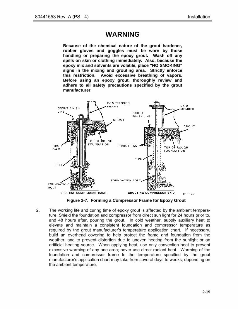
80441553 Rev. A (PS - 4) Installation
2-19
WARNINGBecause of the chemical nature of the grout hardener,rubber gloves and goggles must be worn by thosehandling or preparing the epoxy grout. Wash off anyspills on skin or clothing immediately. Also, because theepoxy mix and solvents are volatile, place "NO SMOKING"signs in the mixing and grouting area. Strictly enforcethis restriction. Avoid excessive breathing of vapors.Before using an epoxy grout, thoroughly review andadhere to all safety precautions specified by the groutmanufacturer.
Figure 2-7. Forming a Compressor Frame for Epoxy Grout
2. The working life and curing time of epoxy grout is affected by the ambient tempera-ture. Shield the foundation and compressor from direct sun light for 24 hours prior to,and 48 hours after, pouring the grout. In cold weather, supply auxiliary heat toelevate and maintain a consistent foundation and compressor temperature asrequired by the grout manufacturer's temperature application chart. If necessary,build an overhead covering to help protect the frame and foundation from theweather, and to prevent distortion due to uneven heating from the sunlight or anartificial heating source. When applying heat, use only convection heat to preventexcessive warming of any one area; never use direct radiant heat. Warming of thefoundation and compressor frame to the temperature specified by the groutmanufacturer's application chart may take from several days to weeks, depending onthe ambient temperature.

Installation 80441553 Rev. A (PS - 4)
2-20
WARNINGAll precautionary measures specified by the OccupationalSafety and Health Act of 1970 (OSHA) must be compliedwith when storing, handling or using solvents.
3. To ensure proper bonding of the grout to the compressor frame (or skid surfaces),clean these surfaces by sandblasting (as stated earlier) or wire brushing. Aftersandblasting or wire brushing, apply solvent provided by the grout manufacturer. Forbest results, complete the surface preparation just before grouting.
CAUTIONGrout must be "flowed" into place, otherwise voids willresult causing a reduction in the "keying" (adhesion)ability of the grout.
4. After the grout has thoroughly set per the manufacturer's instructions, back out theleveling screws, or remove wedges as applicable.
5. Torque the foundation bolt nuts to the value specified by selecting the proper boltsize and pre-stress for Type 1 Jake Bolts or Type 2 J-Bolts, then check appropriatestandard torque table in CHAPTER 5, GENERAL DATA.
7. Recheck all leveling points to be sure that the compressor was not disturbed duringthe grouting process.
2.13.3. Mixing and Pouring of Grout
Prior to grouting, all materials and equipment should be readily available such as:
• Low speed mixer or other container for mixing grout (Low speed mixing reducesair entrapment)
• Containers for transferring and pouring of grout• Caulking gun to seal any joints leaking grout• Metal spouts or funnels to facilitate pouring of grout• Protective gloves, clothing, goggles, air mask, etc.• Cleaning solvent for cleaning equipment, tools and wiping up spilled grout
Grout material temperature, both epoxy and aggregate, must be maintained between50º F and 90º F prior to mixing. Grout should be mixed according to the proceduresrecommended by the grout manufacturer. Carefully read all mixing information on thepackages and any technical bulletins provided. If in doubt about the mixing procedures, callthe manufacturer.
Pour grout from one end of the compressor and work toward the other end in anorderly fashion. Use wheelbarrows or buckets to transport grout to the placement area.Placement should be rapid and continuous so as to avoid cold joints and voids under theequipment. The grout should flow into place. Continue to fill with grout until it reaches the

80441553 Rev. A (PS - 4) Installation
2-21
top edge of the form. At this level, the grout should be 1/2 to 3/4 inches (13 to 19 mm) upthe sides of the compressor frame if full-bed grouting is used.
Epoxy grout cannot be trimmed after it has set. After initial hardening, a smoothfinish can be achieved by troweling with a steel trowel wetted with solvent. Bubbles can bebroken by LIGHTLY spraying with solvent or soapy water. All further finishing will requiregrinding after cure period is complete.
2.13.4. Curing of Grout
Grout should be cured in accordance with the grout manufacturer's specificationsand recommendations. Read and follow directions printed on packages and technicalbulletins. The temperature of the frame/skid and foundation block or mat should bemaintained between 50º and 90º F (10º and 32º C) during grouting and for a minimum of 24hours thereafter. Recheck all leveling points to be sure that the frame alignment was notdisturbed during the grouting period. If the unit is out of alignment, it will have to be re-grouted.
2.13.5. Tightening Foundation Bolts
After the grout is cured, back out or remove the leveling screws. Place a dialindicator near each foundation bolt so that it will read the flange deflection when thefoundation bolts are tightened. Tighten the foundation bolts to the proper torque byselecting the proper bolt type (as indicated in Figure 2-1), size and pre-stress. Then selectthe torque values from the appropriate Standard Torque Table in CHAPTER 5, GENERALDATA. If a deflection of 0.0015 (0.04 mm) or greater is indicated, there may be a pocket orvoid under the frame, or defective grout material was used.
2-14. DRIVER INSTALLATION AND ALIGNMENT
There are three compressor drive arrangements possible. The standard drivearrangement used on the PET Star 4 compressor is induction and V-belt. The followinginformation applies generally to the installation of this drive arrangement. Refer to theinstructions supplied by the manufacturers of the particular drive components for specificinformation on installation and alignment.
NOTE
The driver is installed and aligned with the compressor by thepackager on skid-mounted units. However, it is a goodpractice to recheck the alignment of the drive arrangementbefore starting the machine for the first time.
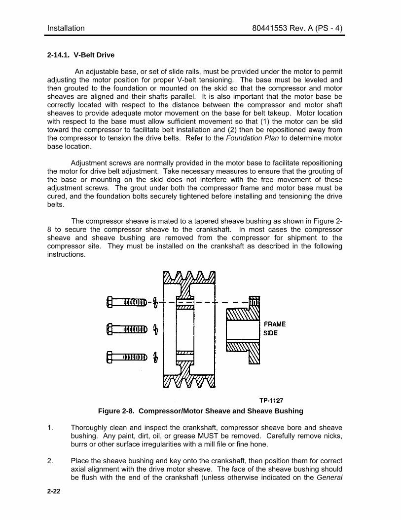
Installation 80441553 Rev. A (PS - 4)
2-22
2-14.1. V-Belt Drive
An adjustable base, or set of slide rails, must be provided under the motor to permitadjusting the motor position for proper V-belt tensioning. The base must be leveled andthen grouted to the foundation or mounted on the skid so that the compressor and motorsheaves are aligned and their shafts parallel. It is also important that the motor base becorrectly located with respect to the distance between the compressor and motor shaftsheaves to provide adequate motor movement on the base for belt takeup. Motor locationwith respect to the base must allow sufficient movement so that (1) the motor can be slidtoward the compressor to facilitate belt installation and (2) then be repositioned away fromthe compressor to tension the drive belts. Refer to the Foundation Plan to determine motorbase location.
Adjustment screws are normally provided in the motor base to facilitate repositioningthe motor for drive belt adjustment. Take necessary measures to ensure that the grouting ofthe base or mounting on the skid does not interfere with the free movement of theseadjustment screws. The grout under both the compressor frame and motor base must becured, and the foundation bolts securely tightened before installing and tensioning the drivebelts.
The compressor sheave is mated to a tapered sheave bushing as shown in Figure 2-8 to secure the compressor sheave to the crankshaft. In most cases the compressorsheave and sheave bushing are removed from the compressor for shipment to thecompressor site. They must be installed on the crankshaft as described in the followinginstructions.
Figure 2-8. Compressor/Motor Sheave and Sheave Bushing
1. Thoroughly clean and inspect the crankshaft, compressor sheave bore and sheavebushing. Any paint, dirt, oil, or grease MUST be removed. Carefully remove nicks,burrs or other surface irregularities with a mill file or fine hone.
2. Place the sheave bushing and key onto the crankshaft, then position them for correctaxial alignment with the drive motor sheave. The face of the sheave bushing shouldbe flush with the end of the crankshaft (unless otherwise indicated on the General

80441553 Rev. A (PS - 4) Installation
2-23
Arrangement). If it is difficult to slide the sheave bushing onto the shaft, wedge ascrewdriver blade into the saw cut to relieve the fit.
3. Attach the compressor sheave to an overhead hoist, then place the sheave over thesheave bushing and onto the crankshaft. Align the drilled holes in the compressorsheave with the threaded holes in the sheave bushing.
4. Install the capscrews through the compressor sheave into the sheave bushing flangeand hand-tighten them. DO NOT lubricate the capscrews. Make sure a lockwasheris placed under each capscrew head.
5. With the drive properly aligned, tighten all capscrews evenly and progressively inrotation to the torque value listed in Table 2-2.
Table 2-2. Sheave Bushing Tightening Information
Bushing Size Size & Thread of Capscrew Torque, ft-lbs (N·m)
QTJA
SH-SDS-SDSKSFEFJMNPWS
1/4 x 1No. 10–24
1/4–205/16–183/8–161/2–13
9/16–125/8–113/4–107/8–91–8
1-1/7–71-1/4–7
9 (12)5 (7)
9 (12)15 (20)30 (41)60 (81)
110 (149)135 (183)225 (305)300 (407)450 (610)600 (814)
750 (1017)
CAUTIONThe tightening force on the capscrews is multiplied manytimes by the wedging action of the tapered sheavebushing. If extreme tightening force is applied, or if alubricant is used, bursting pressures will be created in thesheave hub.
6. Recheck the drive alignment. If the sheave bushing has setscrews over the key,tighten them.
7. Install the motor sheave and motor sheave bushing in a similar manner.
2-14.1.1. V-Belt Tensioning
This method is recommended for V-band drives where larger deflecting forces makethe use of force deflection method impractical.

Installation 80441553 Rev. A (PS - 4)
2-24
Elongation is related to the tension causing it; thus, tape measured V-band lengths,both slack and tight, can be used to obtain proper V-band tension.
1. Decrease the center distance until the V-band(s) can be easily slipped into thesheave grooves. Forcing the belts on can damage the load-carrying cords and causepremature belt failure.
2. With the V-band(s) still on the drive at NO tension, measure the outsidecircumference (slack O.C.) of the bands.
NOTE
If retensioning a used drive, decrease the center distance untilthere is no tension on the band(s), then measure the outsidecircumference (slack O.C.) of the band(s).
3. Determine the required Static Tension (Ts) per individual rib strand using thefollowing formula.
Ts = (K x DHP) / (N x S) + MS2/2
4. Find a range of recommended tensions.Lower Tension = TsUpper Tension = 1.5 times Ts
5. Calculate minimum and maximum elongated band lengths for use in tensioning thedrive.a. From Table 2-6, find length multipliers corresponding to the lower and upper
Ts values calculated per point 4 above.b. Multiply the slack O.C. found in point 2 by the length multipliers to find the
minimum and maximum elongated band lenghts.
6. Increase the driver center distance until a tape measurement of the band(s) O.C. isbetween the two values calculated for elongated band length mentioned in point 5b.
7. Retension as required. New V-bands may lose tension rapidly during the run-inperiod and will probably require retensioning. V-bands that have been on a drive forsome time may also require retensioning due to tension decay from normal use andwear.
Table 2-3. Explanation of Symbols
Symbol Description
KDHP
NSMYAc
Value depending on D-d/C, Table 2-5Design Horsepower based upon the
recommended application service factorNumber of belts or V-band ribs
Belt Speed, FPM/1000Centrifugal constant, Table 2-4
Belt Constant, Table 2-4Arc of contact – smaller sheave degrees

80441553 Rev. A (PS - 4) Installation
2-25
Table 2-4. Belt Constant M And YNarrowFactors
3V 5V 8VM
Single Belts0.46 1.23 3.28
MV-Band
0.51 1.32 3.80
Y 4.0 12.00 22.00
Table 2-5. K Factors and Arc of ContactD-d/C Arc
ContactDegree
Factor D-d/C ArcContactDegree
Factor
Ac K Ac K
0.000 180 1.000 24.750 0.725 137 0.884 30.1420.025 179 0.997 24.883 0.750 136 0.879 30.4110.050 177 0.994 25.019 0.775 134 0.874 30.6880.075 176 0.990 25.158 0.800 133 0.869 30.9750.100 174 0.987 25.300 0.825 131 0.864 31.2700.125 173 0.983 25.444 0.850 130 0.858 31.5760.150 171 0.980 25.591 0.875 128 0.852 31.8920.175 170 0.977 25.742 0.900 127 0.847 32.2190.200 169 0.973 25.896 0.925 125 0.841 32.5580.225 167 0.969 26.053 0.950 123 0.835 32.9090.250 166 0.966 26.213 0.975 122 0.829 33.2730.275 164 0.962 26.377 1.000 120 0.823 33.6520.300 163 0.958 26.545 1.025 118 0.816 34.0450.325 161 0.954 26.717 1.050 117 0.810 34.4540.350 160 0.951 26.892 1.075 115 0.803 34.8790.375 158 0.947 27.072 1.100 113 0.796 35.3230.400 157 0.943 27.257 1.125 112 0.789 35.7860.425 155 0.939 27.445 1.150 110 0.782 36.2700.450 154 0.935 27.639 1.175 108 0.774 36.7770.475 153 0.930 27.837 1.200 106 0.767 37.3070.500 151 0.926 28.040 1.225 104 0.759 37.8640.525 150 0.922 28.249 1.250 103 0.751 38.4480.550 148 0.917 28.463 1.275 101 0.742 39.0640.575 147 0.913 28.684 1.300 99 0.734 39.7130.600 145 0.908 28.910 1.325 97 0.725 40.3980.625 144 0.904 29.142 1.350 95 0.716 41.1230.650 142 0.899 29.381 1.375 93 0.706 41.8920.675 141 0.894 29.627 1.400 91 0.697 42.7090.700 139 0.889 29.881 1.425 89 0.687 43.580

Installation 80441553 Rev. A (PS - 4)
2-26
Table 2-6. Belt Length Multipliers For Tensioning Banded BeltsNarrow Banded Narrow Banded
8V 8VTs
Per Strand(lbs) 8V1700 &
under8V1800 &
over
TsPer Strand
(lbs) 8V1700 &under
8V1800 &over
10 1.00013 1.00010 120 1.00164 1.0013912 1.00016 1.00012 140 1.00192 1.0016614 1.00019 1.00014 160 1.00220 1.0019416 1.00021 1.00016 180 1.00249 1.0022318 1.00024 1.00018 200 1.00277 1.0025420 1.00027 1.00020 240 1.00335 1.0031924 1.00032 1.00024 280 1.00395 1.0038928 1.00037 1.00029 320 1.00454 1.0046132 1.00043 1.00033 360 1.00515 1.0054336 1.00048 1.00037 400 1.00575 1.0063140 1.00054 1.00042 450 1.00652 1.0074445 1.00060 1.00047 500 1.00732 1.0085950 1.00067 1.00053 550 1.00813 1.0097655 1.00074 1.00058 600 1.00896 1.0109460 1.00081 1.00064 650 1.00982 1.0121365 1.00088 1.00070 700 1.01071 1.0133170 1.00095 1.00076 750 1.00163 1.0144975 1.00101 1.00082 800 1.01257 1.0157180 1.00108 1.00088 850 1.01354 1.0168985 1.00115 1.00094 900 1.01454 1.0188790 1.00122 1.00100 950 1.01561 1.0192795 1.00129 1.00106 1000 1.01667 1.02049
100 1.00136 1.00113
2-14.1.2. Compressor/Motor Sheave Removal
1. Relieve drive tension by shortening the center distance between driver and drivensheaves.
2. Lift of belts.
3. Loosen and remove all the capscrews. If the sheave bushing has keyway setscrews,loosen them.
4. Reinstall the capscrews (three in JA through J bushings, two in QT and M through Sbushings) in the threaded holes in the outer piece of the assembly. Progressivelytighten the capscrews until the compressor/motor sheave is loose on the sheavebushing.
5. Attach the compressor/motor sheave to an overhead hoist, then remove the sheaveand the bushing from the crankshaft/motor shaft. If the bushing will not slip off theshaft, wedge a screwdriver blade in the bushing saw cut to relieve the fit; the bushingcan then be easily removed.
80441553 Rev. A (PS - 4) Installation
2-27
2-15. SAFETY VALVES
WARNINGAlways install a pressure safety relief valve capable ofpassing the full-load capacity of the compressor cylinder,or cylinders, between the cylinder and the first line valve.UNDER NO CIRCUMSTANCES is a shutoff valve allowedin any discharge line before the safety relief valve. Thiscan defeat the purpose of the safety valve.
The compressor must be fitted with safety valves to limit suction pressure, interstagepressure and final pressure to a safe maximum. For this application, the term "safety valve"refers to an automatic, pressure-relieving device that is actuated by the static pressureupstream of the valve and characterized by full opening pop action; these are also oftenreferred to as "pop safety valves".
When a bypass is furnished, or client installed, a suction pressure safety valve mustbe installed immediately before the bypass valve, or on the inlet scrubber. This valve,normally supplied by the client, must be located between the gas line suction shutoff valveand the unit.
NOTE
The pressure at which any safety valve is set to operate mustinclude the effects of static head and constant back pressure.Safety valves are selected for the required pressure settingand also for expected air characteristics and temperature.
Safety valves will be set to blow at pressures somewhat above normal compressoroperating pressures. The maximum pressure setting for a safety valve is the maximumallowable working pressure (MAWP) of the compressor cylinder which it is protecting.Safety valve settings for a specific unit are given in the performance information that isincluded with the job-specific Installation, Operation & Maintenance Manual. The pressureratings of all of the components of the air system are taken into account when selecting apressure setting for a safety valve. This includes the separators, bottles and valves.
Safety valves must be constructed, located and installed so that they are readilyaccessible for inspection and repair and so that they cannot be readily rendered inoperative.They must also meet any Federal, state or local regulations.
Discharge lines from safety valves must be designed to facilitate drainage, and suchlines must lead to a safe place of discharge. The size of the discharge line must be suchthat any back pressure that may exist or develop will not reduce the relieving capacity of thesafety valve below that required to properly protect the compressor.
Further information pertaining to the selection, pressure settings, installation andpiping of safety valve and other relief devices will be found in one of the pressure vesselcodes.

Installation 80441553 Rev. A (PS - 4)
2-28
2-16. INSTALLING CONTROL PANEL & ELECTRICAL WIRING
Install the control panel in accordance with the manufacturer's instructions anddrawings. A section within the compressor Installation, Operation & Maintenance Manual ora separate Control Panel Manual is usually provided.
All motor and control panel wiring must be carefully installed in accordance with theNational Electric Code, the Occupational Safety and Health Act of 1970 (OSHA) and anyother code requirements at the installation site. Check all wiring against the nameplaterating of each item. Connect leads as required to provide the correct rotation.
Most compressors are supplied with protective devices arranged so that it cannot bestarted in the event that certain conditions would be detrimental to its operation. Theselection of switches for a given compressor depends on the degree of protection specifiedby the customer. The interlocking control is typically arranged such that the maincompressor driver cannot be started if: (1) there is insufficient oil pressure in the framelubrication system; and/or (2) the barring device is engaged (if supplied).

PET STAR 4CHAPTER 3
OPERATION AND TROUBLESHOOTING
Paragraph Page
3-1. GENERAL INFORMATION .............................................................................. 3-23-1.1. Inspections and Adjustments ..................................................................... 3-23-1.2. Preparing Prior to Initial start ...................................................................... 3-33-2. COMPRESSOR CONTROLS ........................................................................... 3-53-2.1. Capacity Regulation ................................................................................... 3-53-2.1.1. Constant Speed Control ....................................................................... 3-63-2.1.2. Manual Control ..................................................................................... 3-63-2.1.3. Auto Start / Stop Control ....................................................................... 3-63-3. FRAME LUBRICATION SYSTEM..................................................................... 3-63-3.1. Oil Pressure ................................................................................................ 3-63-3.2. Oil Pressure Relief Valve ........................................................................... 3-63-3.3. Low Oil Pressure Protection ....................................................................... 3-73-3.4. Oil Filter ...................................................................................................... 3-73-3.5. Oil Cooler ................................................................................................... 3-73-3.6. Oil Temperature ......................................................................................... 3-73-3.7. Frame Oil Capacity ..................................................................................... 3-73-3.8. Frame Oil Specifications ............................................................................ 3-83-3.9. Oil Change Schedule ................................................................................. 3-83-4. FRAME LUBE OIL PIPING FLUSHING PROCEDURES.................................. 3-93-4.1. Flushing Preparation .................................................................................. 3-93-4.2. Flushing Procedure .................................................................................... 3-103-5. CYLINDER COOLING....................................................................................... 3-123-5.1. Water-Cooled Cylinders ............................................................................. 3-123-5.2. Water-Cooled Packing ............................................................................... 3-133-5.3. Coolant Console ......................................................................................... 3-143-6. COOLANT RECOMMENDATIONS................................................................... 3-143-6.1. Scale .......................................................................................................... 3-143-6.2. Corrosion .................................................................................................... 3-143-6.3. Fouling ........................................................................................................ 3-153-7. INITIAL STARTUP AND BREAK-IN.................................................................. 3-183-7.1. Initial Startup and Break-in Checks ............................................................ 3-183-7.2. Frame and Running Gear Startup and Break-in Procedure ....................... 3-193-7.3. Non-Lubricated Cylinder Break-in Procedure ............................................. 3-213-8. INSPECTIONS AFTER BREAK-IN ................................................................... 3-213-9. ROUTINE OPERATION.................................................................................... 3-223-9.1. Startup ........................................................................................................ 3-223-9.2. Shutdown ................................................................................................... 3-243-10. ROUTINE OPERATION AND MAINTENANCE CHECKS ................................ 3-243-10.1. Hourly ......................................................................................................... 3-243-10.2. Daily ........................................................................................................... 3-243-10.3. Monthly ....................................................................................................... 3-253-10.4. Semi-Annually ............................................................................................ 3-253-10.5. Annually ...................................................................................................... 3-253-10.6. Periodically (As Dictated By Experience) ................................................... 3-263-11. EXTENDED SHUTDOWN PRECAUTIONS...................................................... 3-263-11.1. Non-Lubricated Cylinder.............................................................................. 3-273-12. TROUBLESHOOTING ...................................................................................... 3-28

Operation And Troubleshooting 80441553 Rev. A (PS - 4)
3-2
3-1. GENERAL INFORMATION
This chapter should be read carefully by the operating and maintenance personnelprior to preparing the compressor for its initial startup. There are four objectives: (1) to fami-liarize the operators and maintenance personnel with necessary operating requirements toensure safe and efficient operation of the unit; (2) to outline the recommended start/stopprocedures for the unit; and (3) to lend assistance in establishing an effective inspection androutine maintenance program; and (4) to provide guidance in troubleshooting problems.
Due to the complexity there are many precautions that must be taken when startingthe unit for the first time. Carelessness or lack of knowledge can result in personal injury orserious damage to the equipment. If at all possible, an Ingersoll-Rand Technical ServiceRepresentative should oversee the initial startup and shutdown of the unit; even then, theregular operators should be well acquainted with the details of the machine and with theprecautions to be taken, and the reasons for them, when starting or stopping thecompressor.
When a pre-start checklist is developed for the unit and the operators have gainedknowledge and experience through repetitive startups and shutdowns, startup shouldbecome a safe and routine procedure.
WARNINGCompressor cylinders are carefully selected to fit thespecified operating conditions and the horsepower ratingof the machine. If it becomes necessary to vary theoperating conditions from those specified at the time themachine was ordered, review the situation with ournearest sales office. Changes to the equipment may berequired to avoid serious overload or other majorproblems that could lead to a life-threatening accident ordamage to the equipment.
3-1.1. Inspections and Adjustments
WARNINGAir compressors require strict maintenance in order tooperate safely and efficiently. It must be understood thatthe compression of ANY gas is an inherently hazardousoperation, and all pertinent safety precautions given inthis manual must be strictly followed. The proper tight-ening, and periodic re-tightening, of fasteners must beconsidered a top priority routine maintenance function.Failure to follow correct and safe maintenance practicescan result in a serious, life-threatening accident ordamaged equipment.

80441553 Rev. A (PS - 4) Operation And Troubleshooting
3-3
Thoroughly inspect the entire machine, both inside and out, to be certain that thereare no loose parts or tools where they can cause damage or interfere with startup, and thatnothing has been tampered with since installing the unit.
Check, and tighten as required, all bolts and nuts to be sure that all is in readinessfor starting. Refer to CHAPTER 5, GENERAL DATA, for tightening requirements and torquespecifications. Some fastener locations require a specific torque, and these are listed in aspecial table. All other fasteners are to be tightened to the torque indicated in the standardtorque table, based on the fastener size and its usage (with or without a gasket, etc.). Allfasteners must be tightened using the stretch method or a calibrated torque wrench; noother method is approved by Ingersoll-Rand Company. The use of air-operated impactwrenches for final tightening of fasteners shall be absolutely prohibited.
Prior to compressor startup, check compressor piston rod cold runout. Piston endclearances should be checked. Detailed instructions for measuring and adjusting endclearances and piston rod runout are given in CHAPTER 4, MAINTENANCE.
WARNINGAll rotating power transmission products are potentiallydangerous and must be properly guarded in compliancewith OSHA standards. Failure to install proper guards canresult in a life-threatening accident.
3-1.2. Preparing for Initial Start
The following instructions for cleaning, inspecting and preparing the compressor forits initial startup should be closely followed. These instructions are also applicable wheneverthe unit has been extensively overhauled.
1. Be certain that all of the instructions given in CHAPTER 2, INSTALLATION, havebeen complied with and that the foundation and grout are completely cured beforestarting the unit.
2. To minimize the chance of dirt getting into the compressor while the covers are offfor inspections, wash down the foundation and area around the compressor. Wipedust and dirt off the frame and compressor drive, as well as the compressor cylindersand any overhead piping.
3. Inspect the unit to make sure that all parts are properly installed, tightened and/oradjusted in preparation for start-up. Also check the motor (or other drivingequipment) and that all auxiliary components are correctly adjusted and ready forstart-up.
4. If not already in place, install the piston rod packing and oil scrapers.
5. Remove at least one valve from each end of every cylinder and inspect the valve,cylinder bore and cylinder gas passages for dirt or other foreign material. If there isany doubt concerning the cleanliness of a particular cylinder or cylinders, all of thevalves must be removed from that unit and the cylinder thoroughly examined. Leave

Operation And Troubleshooting 80441553 Rev. A (PS - 4)
3-4
out at least one valve from each end of every cylinder for the initial start-up andbreak-in. This will help ensure a light load on the unit.
6. For critical non-lube applications, it is recommended that all compressor valves beremoved, disassembled, cleaned and reassembled prior to operating thecompressor, as there can be no assurance that there is no preservative oil within thevalve assemblies. Specific valve instructions can be found in the appropriate sectionof the job-specific Installation, Operation & Maintenance Manual prepared for yourmachine.
7. Turn on the cooling water and check for leakage. Make sure the cooling system isfilled by checking the vent valve(s) and that flow is indicated at the sight flowindicators. Refer to Paragraph 3.5 for instructions on filling and regulating thecooling water system.
WARNINGCompressor cylinders must be depressurized toatmospheric pressure before barring. Compressorpistons will move to bottom-dead-center as an equilibriumcondition due to the difference in piston surface area (bypiston rod cross sectional area) exposed to the system airpressure. Failure to depressurize the compressorcylinders prior to barring may result in unexpectedrollover that can cause personal injury.
WARNINGBefore barring the unit over, the operator must ensurethat the driver will not start by locking out and tagging outequipment, making sure that power cannot be turned onaccidentally. Failure to heed this WARNING could resultin a fatal accident if the unit starts over unexpectedly.
8. Bar over the unit several revolutions in the direction of rotation to make sure therunning gear is clear, that it works freely and that everything is clear and ready foroperation.
9. Check each protection device for proper operation. This testing should be done withthe compressor drive motor power disconnected. Reset the control panel after eachdevice is tested.
10. Thoroughly inspect the entire compressor, particularly overhead areas, to be surethere are no loose parts, debris or tools where they can cause damage (by fallinginto the motor or onto accessory equipment). Make sure nothing has been tamperedwith since installation.
11. Inspect all piping for strain, misalignment or loose connections, and closed handvalves or "blinds" which may not have been removed.

80441553 Rev. A (PS - 4) Operation And Troubleshooting
3-5
12. Air Piping installed at customer site or after extensive overhaul should be blown outwith nitrogen or with another inert dry gas. During this operation the cylinder flangesshould be blanked off to prevent contamination of the cylinder(s). When blowing outthe volume of the purging gas passed through the pipe must be great enough tocreate a velocity that is capable of lifting and carrying out any foreign material. Theoperation must be carried out until the piping is clean.
WARNINGTake necessary precautions to adequately protect thelungs, skin and eyes against dust and flying debris whenusing high volume or pressurized gases.
3-2. COMPRESSOR CONTROLS
Many installations include a large computer for plant wide or system wide processmonitoring and control. However, a local control panel is usually located in the operatingarea of the compressor. The local control panel incorporates protective controls, start/stopcontrols, auxiliary controls, status indicators, capacity regulation, pressure, temperature, andother system indicators and signals interfacing with the main computer or control system.Refer to the Control Panel section/manual for information on your particular installation.
In addition, electrical interlocks are usually installed to ensure that certain pre-startupfunctions have been performed before the compressor can be started. Typically, theseinclude: (1) the frame oil system is pressurized; (2) the barring jack is disengaged (ifsupplied).
3-2.1. Capacity Regulation
Capacity regulation is the process of temporarily changing the capacity of acompressor by some planned and controlled means. A job-specific Piping andInstrumentation Diagram is prepared for each compressor installation and is included in theInstallation, Operation & Maintenance Manual.
NOTE
Initial start up air of instrument quality to be provided. Once themachine starts on full load customer has to close the supply ofstart up air connection and let the regulation air take control.
Two basic methods for controlling capacity of a compressor are: (1) inlet valve/portunloading; and (2) clearance pocket unloading. Sometimes both of these methods are usedtogether. The standard form of capacity control provided on the PET STAR 4 compressor isthrough inlet valve/port unloading. In either case, capacity is reduced in fixed increments orsteps. Depending on the number of cylinder ends utilized for capacity control and thenumber and size of clearance pockets, the step changes in capacity can be large orrelatively small. On the PET STAR 4 compressors we are providing three step controlthrough inlet valve/port unloading as the standard i.e. 0-50-100% capacity control.

Operation And Troubleshooting 80441553 Rev. A (PS - 4)
3-6
3-2.1.1. Constant Speed Control
The compressor will load and unload automatically as long as there are notrips or stops. Even when the machine is running unloaded for more than 30minutesit will continue to run. It is the responsibility of the customer to stop the compressor ifthe unit is running unloaded for more than 30minutes.
3-2.1.2. Manual Control
The compressor will run continuously in 0%, 50% or 100% capacity as perselection from Control panel SETTINGS folder. Under this condition if the customerdecides to run the unit in 0% (unloaded) condition then it is the responsibility of thecustomer to stop the compressor if it runs for more than 30minutes.
3-2.1.3. Start / Stop Control
The compressor will load and unload based on the air system requirement. Inthis control mode if it runs unloaded for 30minutes the compressor will stopautomatically. The recommended unloaded shutdown timer setting should not beless than 20minutes and not more than 30minutes.
3-3. FRAME LUBRICATION SYSTEM
The frame lubrication system utilizes positive pressure to supply oil to bearings andrunning gear components. Refer to the job-specific Piping and Instrumentation Diagram fordetails of your particular installation.
The compressor is equipped with a shaft-driven main oil pump and an auxiliarymotor-driven oil pump. The auxiliary oil pump is used to pressurize the lubrication systemprior to startup and is arranged to start automatically if the main oil pump fails. After thecompressor is started, the auxiliary oil pump is shut off and the main oil pump supplies lubeoil to the frame lube oil system while the compressor is in operation. A check valve locatedin the auxiliary oil pump discharge line prevents oil flow through this line when the auxiliarypump is not in operation.
3-3.1. Oil Pressure
When installed, the oil pressure control valve is normally set to maintain the oilpressure downstream of the oil filter at 60 PSIG (414 kPa). This will result in an oil pressureat the end of the main bearing oil header of approximately 50 PSIG (345 kPa). Theoptimum crankcase oil pressure for the compressor is 45 to 55 PSIG (310 to 379 kPa).
3-3.2. Oil Pressure Relief Valve
The oil pressure relief valve is factory set at 90 PSIG and needs to be re-set toapproximately 70 PSIG oil pressure at the relief valve. This will provide the required 50 to 60PSIG oil pressure at the end of the oil header pipe where the oil pressure is taken. This

80441553 Rev. A (PS - 4) Operation And Troubleshooting
3-7
valve is located on the discharge side of the frame oil pump and relieves excessive pressureto the sump. Refer to the job-specific diagrams for details of your particular system.
3-3.3. Low Oil Pressure Alarm & Shutdown Protection
Main bearing oil header pressure is monitored by low oil pressure alarm andshutdown switches/transducers. The alarm setting is at 35 PSIG (241 kPa) while theshutdown setting is at 25 PSIG (172 kPa), unless otherwise noted on the job-specificdiagrams. The switches/transducers are normally electrically connected to a control panelthat produces an audible signal or an indicating light. In the event of a low oil pressurealarm or shutdown, check the lube oil system components thoroughly and correct the causeto restore normal pressure. Common causes of low oil pressure include:
1. Low oil level. 2. Excessive oil leakage. 3. Obstructed oil pump suction strainer. 4. Air leakage into pump suction line through breaks or loose fittings. 5. Worn pump elements. 6. Clogged filters.7. Dilution of oil.
3-3.4. Oil Filter
A spin on type 10 micron full flow oil filter that is non-bypassing will be supplied asstandard. The filter is a spin on type where the filter elements have a collapse rating of100psi differential pressure. The filter assembly can be also be equipped with an optionaldifferential pressure alarm switch set at 15 PSID (103 kPa) to indicate a clogged filter.
3-3.5. Oil Cooler
The oil cooler is normally a brazed plate type and is designed to maintain an oilsupply temperature at or below 130ºF (54ºC). The cooler is water-cooled. The cooler isnormally mounted on the compressor skid.
3-3.6. Oil Temperature
The oil supply temperature is normally controlled by an automatic 3-way thermostaticvalve in conjunction with the oil cooler. The thermostatic valve is normally set at a nominal150ºF (66ºC). The 3-way thermostatic valve continually modulates the oil flow to maintainthe nominal temperature by diverting the flow of oil through and around the cooler. Amanual override may be provided to divert the entire flow of oil through or around the oilcooler as needed.
3-3.7. Frame Oil Capacity
The frame oil sump is fitted with an oil level gauge at the pump end of the frame.Maintain an oil level approximately half-way up the gauge while the compressor is operating.

Operation And Troubleshooting 80441553 Rev. A (PS - 4)
3-8
Standard oil sump capacity is listed in Table 3-1. When the crankcase is first filled, the oillevel on the gauge glass should be slightly higher than half-way; this is normal. Placing thecompressor into operation will cause the oil level to drop somewhat, since a portion of the oilwill be filling the various pipes, components and header, resulting in less oil in the sump.
Check the oil level periodically as part of the normal operating routine, and maintainthe oil level (with the unit running) at the center of the oil level gauge. Oil can be added tothe frame sump while the unit is running by removing the breather cap (located on side ofthe frame) and pouring the oil into the breather tube. Do not overfill the sump to a pointwhere the rotating parts will strike the oil surface; this will cause foaming and loss of oilpressure from the frame oil pump. Too low an oil level also may result in air being entrainedin the oil, causing fluctuating or total loss of oil pressure to the bearings. When thecompressor is shutdown, the oil level will be well above the line on the gauge glass.
Table 3-1. PET STAR 4 Standard Frame Oil Sump Capacity
No. of Crank Throws 4
Oil Capacity, gal (L) 22.12 (84)
3-3.8. Frame Oil Specifications
The frame oil must be a well-refined petroleum product. It should not contain fats orfixed oil compounding. Oil containing rust and oxidation inhibitors, and foam depressant ispreferred. It must be substantially non-corrosive to the common bearing metals. The pourpoint of the oil should be at least 10°F (6°C) below ambient starting temperature with thefollowing additional physical and chemical properties listed in Table 3-2. DO NOT use multi-grade oils or viscosity improvers.
Table 3-2. Frame Oil Specifications
Flash Point (Open Cup) 380º F (193º C) Minimum
Viscosity @ 100º F (40º C) 780 SSU (175 cSt) Maximum
Viscosity @ 210º F (100º C) 60 SSU (10 cSt) Minimum
Carbon Residue 0.45% Maximum
Strong Acid Number 0.00 Maximum
3-3.9. Oil Change Schedule
Our recommendation is that the frame oil be changed and the oil filter cartridge (orfilter elements) be replaced after the initial 24 to 72 hours of operation on a new or rebuiltunit. Thereafter, it should not be necessary to change the oil more often than every 4000 to8000 hours, depending on the local operating conditions. Where the compressor isoperated intermittently, or where the oil reaches high temperatures due to very hot ambienttemperatures, it will be necessary to change the oil more often. Most reputable oilcompanies offer laboratory analysis of oil samples if requested to do so. We highlyrecommend the use of this service.

80441553 Rev. A (PS - 4) Operation And Troubleshooting
3-9
3-4. FLUSHING THE FRAME LUBE OIL PIPING
The purpose of flushing the frame lube oil piping of a new compressor is to removeany foreign material that may have been left in the external piping after it was cleaned. Thepiping within the frame itself has been flushed at the factory, and may have been usedduring a mechanical run test. If the compressor has been overhauled, the cast-in oil headerand main bearing oil passages must be cleaned before the running gear is installed.
3-4.1. Flushing Preparation
Before flushing, the external oil piping must have been cleaned. If it is carbon steel, itmust have been acidized to remove any rust or scale. Ingersoll-Rand recommends that:
1. The frame lube oil filter(s) be located as close to the main bearing oil header inlet aspossible to minimize the length of lube oil piping downstream of the filter(s).
2. The frame lube oil piping downstream of the lube oil filter(s) be stainless steel.
3. The flushing oil flow must be at least 110% of the main oil pump flow. Most unitshave auxiliary oil pumps that meet this requirement and can be used for flushing.However, if the auxiliary oil pump does not have this capacity, a temporary flushingpump of sufficient capacity must be used. If the unit has two electric oil pumps,instead of a shaft- driven oil pump and an auxiliary oil pump, these two pumps canbe run simultaneously to obtain the required oil flow.
4. A light weight SAE 10 oil must be used for flushing. This is usually a rust andoxidation inhibited (R&O) circulating oil or turbine oil.
5. The flushing oil must be preheated to a minimum 150ºF (66ºC). The frame oil heateris usually insufficient for this purpose. This can usually be accomplished by passinghot water or low pressure steam through the frame lube oil cooler tubes. If using lowpressure steam, take care to avoid steam hammer that may rupture the cooler tubes.
6. It will be necessary to flush both the lube oil cooler(s) and the cooler bypass line(s).This can be accomplished in several ways:
a. If the lube oil temperature control valve (TCV) has a manual override, this canbe used to divert the oil through the cooler and then the bypass line. If thisoption is available and the lube oil temperature control valve (TCV) is athermostatic type, care must be taken such that the oil temperature does notexceed 25º F (14º C) over the design temperature of the thermostat elementsor “pills”.
b. Remove the thermostat elements or pills from a thermostatic type lube oiltemperature control valve. A skillet or blind can be placed in the oil cooler or
cooler bypass line connection as desired. However, be sure that thenecessary replacement gaskets and O-rings are available beforedisassembling the temperature control valve.
c. Replace the lube oil temperature control valve with a temporary tee. A skilletor blind can be placed in the oil cooler or cooler bypass line connection as

Operation And Troubleshooting 80441553 Rev. A (PS - 4)
3-10
desired.
d. If an external pressure control valve (PCV) is used, the return line from thispressure control valve to the compressor frame must be flushed. This can bedone by simply replacing the pressure control valve (PCV) with a spool piece,or lowering the setpoint of the pressure control valve (PCV) until it is fullyopen.
3-4.2. Flushing Procedure
1. Remove the frame top covers and frame extension/crosshead barrel covers. Closelyinspect the interior of the frame and all the running gear surfaces for dirt or otherforeign material which may have entered during the compressor installation oroverhaul.
2. Thoroughly clean the interior of the frame with a safety solvent, paying particularattention to pockets or crevices where dirt and other foreign material can lodge. Therunning gear parts of a new compressor are coated with an oil-soluble rustpreventative. This need not be removed, unless it has been contaminated with dirt orother foreign material. The interior of the frame is coated with an oil-proof paint,which should not be scraped or removed during cleaning.
3. Visually inspect the interior of the lube oil piping between the lube oil filter(s) and themain bearing oil header inlet. If it contains rust or scale, or is dirty; it must be acidizedor cleaned prior to flushing.
4. DO NOT flush through the cast-in main bearing oil header and drilled passages atthis time.
5. Temporary piping or hoses must be installed from the external oil piping flange, thatnormally connects to the main bearing oil header inlet, into the frame sump.
6. Install a temporary 100 mesh screen at the connection between the external oilpiping and the temporary piping or hoses. Ideally this should be a conical screen witha perforated metal back-up (i.e. witch’s hat). If this is not available, use a flat 100-mesh screen with a heavier 30-mesh screen or perforated metal skillet back-up toprevent the 100-mesh screen from rupturing.
7. If possible, install a pressure gauge upstream of the screen to monitor the pressuredifferential across the screen.
8. The cast-in main bearing oil header should be visually inspected to ensure that isclean. This is best done by removing the flange from the blind end. If there is anysuspicion of dirt, the header should be cleaned by pulling lint free rags soaked insafety solvent through the header until clean. Take great care not to leave anyportions of rag in the main bearing oil header.
9. Clean the lube oil filter casing(s) and install clean lube oil filter element(s). If it is aduplex filter, it will be necessary to flush through both filter cases in-turn, thus cleanfilter elements must be installed in both filter cases.

80441553 Rev. A (PS - 4) Operation And Troubleshooting
3-11
10. Ensure that drain valves have been installed on both the dirty oil and clean oil sidesof the oil filter case(s), and the oil side of the oil cooler(s).
11. Fill the oil sump with the light-weight SAE 10 flushing oil. As the pump fills the oilpiping, the oil level in the frame will drop. Ensure that oil covers the pump suction.
12. Begin flushing through the oil cooler and heat the oil until it reaches a minimum of150ºF (66º C).
13. Bleed any air from the top of the oil filter case(s). An air pocket in the filter case willreduce the effective filter element area.
14. Monitor the lube oil filter differential pressure. If it reaches the maximum differentialpressure recommended by the manufacturer, usually 20 PSI (1.4 kg/cm2), theelements must be replaced before flushing continues.
15. When changing filter elements, take care to prevent dirty oil entering the clean oilside of the filter case. First block off the lube oil filter, then drain the dirty oil side ofthe filter case, and finally drain the clean oil side of the filter case. Only when bothsides of the filter case are completely drained, should the top of the filter case beremoved and the filter element(s) removed.
16. Monitor the pressure differential across the temporary screen. If necessary; stopflushing, and remove and clean the screen.
17. Flush for approximately 4 hours, and then remove and inspect the temporary screen.If the screen is dirty; clean and reinstall, and flush for an additional 4 hours.Continue this process until the screen is clean after flushing for 4 hours.
18. Flush through both the lube oil cooler and cooler bypass line. If duplex lube oilcoolers are used, flush through both coolers and both cooler bypass lines. Vent airfrom the oil side of the cooler as required.
19. If duplex lube oil filters are used, flush through both filters until the temporary screenis clean after flushing for 4 hours.
20. If an external pressure control valve (PCV) is used, flush the return line from thispressure control valve to the compressor frame.
21. After the temporary screen is clean after flushing for 4 hours, a white rag or whitesock should be wired over the end of the temporary piping or hoses.
22. Flush for an additional 4 hours, and then remove and inspect the rag or sock. If therag or sock is dirty, clean or replace and flush for an additional 4 hours. Continueuntil the white rag or sock is clean after flushing for 4 hours.
23. After the white rag or sock comes clean, disconnect the temporary piping or hoses.Reconnect the external oil piping to the main bearing oil header inlet, leaving thetemporary screen at this location.
24. Continue flushing through the main bearings and running gear for approximately 8hours. Rotate the crankshaft approximately 1-1/4 turns every 1 to 2 hours. When

Operation And Troubleshooting 80441553 Rev. A (PS - 4)
3-12
completed, drain the flushing oil from the frame, piping, oil cooler(s), oil filter case(s),etc.
25. After draining the oil filter case(s); remove the elements and install new elements.
26. Remove, clean and reinstall the temporary screen at the main bearing oil headerinlet connection.
27. If the Ingersoll-Rand representative is released from the job site before thetemporary screen is inspected and/or removed, the client is responsible for theinspection and ultimate removal of the screen.
28. Fill the frame, piping, etc. with the recommended frame lube oil.
29. Run the auxiliary oil pump and inspect the interior of the frame for any leaks, and toensure that the oil supply is reaching all the main bearings, crankpin bearings,crosshead pin bushings and shoes.
3-5. CYLINDER COOLING
The method of cooling the compressor cylinders depends on the type of cylinder andthe operating conditions. The cylinder can be air cooled or cooled by water or a coolantsolution in either a closed-loop or open circulating type system. When a coolant (such asethylene glycol and water mix) is used, it can be circulated under pressure through thecylinder jackets. In certain applications, the static or thermosyphon cooling methods may beused. The method of cooling must be taken into consideration when initial engineering isdone for each compressor installation.
3-5.1. Water-Cooled Cylinders
Cooling water removes some of the heat generated by compression and frictionwithin the cylinders and also serves to distribute heat throughout the cylinder to maintaindimensional stability within the cylinder bore. If it does not remove the heat effectively, wearmay be excessive and efficiency diminished. Use only clean, soft water and, if the properquantities are circulated through the cylinders, no trouble should be encountered.
When filling the cooling system, it is important that all air is removed from thecylinder passages and jackets to assure complete and uniform cooling of the cylinder duringoperation.
NOTE
To prevent condensation from developing on the cylinder wallsand gas passages on all cylinders compressing wet gas, thewater inlet temperature to the cylinder should be at least 10º F(5.6º C) above the air suction temperature.
If the water inlet temperature is above the air inlet temperature to the cylinder, nocondensate will form in the cylinder bore.

80441553 Rev. A (PS - 4) Operation And Troubleshooting
3-13
Should condensate form on the cylinder walls and air passages, it will tend to breakdown the lubricating oil (if lube compressor) and cause excessive wear to the cylinder bore,piston rings and valves, and possibly result in valve breakage.
Should the coolant flow be reduced to a rate that is too low, the possibility of buildingup deposits to the point of cutting off all flow exists. If this occurs, the cylinder will overheatand the piston may seize or wear may be excessive and efficiency diminished. The onlyinsurance against scale or mud is the use of clean, soft water and periodic cleaning of thecylinder water jackets. Prior to the initial starting, we recommend disconnecting water linesat the cylinder and cooler outlets and thoroughly flushing the system.
PET STAR 4 compressors normally use a temperature-controlled cooling systemwhere the coolant (soft water) is circulated continuously. Should the compressor beinadvertently started without turning on the coolant flow, shut the unit down immediately. Donot circulate the coolant until the cylinder walls have had a chance to cool, otherwise acracked cylinder wall may result. If non-temperature controlled coolant can be circulatedindependent of the compressor operation, and where the compressor is to be shut down formore than 10 minutes, do not allow the coolant to circulate through the system or it cancause condensate to form on cylinder walls.
After the compressor has been started and operated long enough for operatingtemperatures to stabilize, regulate the supply of cooling water to give the proper cooling.Periodically vent the cylinder cooling system to remove any trapped air. Refer to the job-specific cooling system diagrams supplied for your compressor.
CAUTIONIf freezing of the coolant in the jacket is permitted tooccur, serious damage to the cylinder including crackingof the cylinder barrel is likely.
Unless the system is protected by antifreeze, completely drain the cooling systemduring shutdown periods if the unit will be exposed to freezing temperatures.
If circulating water is dirty, mud will be deposited in the cylinder wall jackets and willeventually restrict the flow of water, unless special care is used to prevent such anaccumulation. The cylinder water jacket or hand hole covers should be removed and thewater jackets and passages inspected. If any mud or other deposit is found, clean it outthoroughly and flush the jackets with water.
3-5.2. Water-Cooled Packing
Some piston rod pressure packing assemblies require water cooling, in which casethe following requirements must be noted:1. The water supply must be clean, filtered to 125 microns and treated to prevent
corrosion or plugging of the water passages in the packing cups. The coolanttemperatures should not exceed 90º F (32º C).
2. A minimum supply of one gallon per minute (3.8 liters/minute) per inch of piston roddiameter is required for each packing assembly. The required flow rate for a

Operation And Troubleshooting 80441553 Rev. A (PS - 4)
3-14
particular packing is usually specified for each application, along with inlet pressurerequirement. Refer to the job-specific cooling system diagrams supplied for yourcompressor.
3. Cooling is required at all times during operation, but must be turned off when the unitis not operating.
4. Small O-rings are used between the packing cups to seal the water passages; theserings must be correctly assembled and maintained in good condition to preventleakage. All packings currently supplied are equipped with O-rings, even thoughwater cooling is not required for all applications.
3-5.3. Coolant Console
Most compressors will use a separate coolant console to provide temperature-andpressure-controlled coolant to the compressor. Refer to the job-specific instructions anddrawings for operating information.
3-6. COOLANT RECOMMENDATIONS
1. In general, the coolant used is water. 50/50 mixture of water and ethylene glycol canalso be used. Occasionally, propylene glycol will be used to combat certaincorrosives. Whenever coolant other than water is used please contact your nearestIngersoll-Rand office.
2. The cooling water supply must be filtered to 125 micron and treated to preventcorrosion or plugging of the water passages in the packing cups.
3. A minimum supply of 1 GPM (3.8 LPM) per inch of rod diameter at 90ºF (32ºC)maximum is recommended for each packing assembly.
4. "Hardness" should be less than 75 ppm; carbonates (such as CaCO3) should be lessthan 45 ppm; dissolved solids should be less than 75 ppm.
3-6.1. Scale
Scale formation inhibits effective heat transfer, yet it does help prevent corrosion.Therefore, a thin uniform coating of calcium carbonate is desired on the inner surfaces.Perhaps the largest contributor to scale formation is the precipitation of calcium carbonateout of the water. This is dependent on temperature and pH. The higher the pH value greaterthe chances of scale formation. Scale can be controlled with water treatment.
3-6.2. Corrosion
Corrosion problems associated with cooling water are identified as several types ofimpurity:
1. Hardness - causes scale formation.

80441553 Rev. A (PS - 4) Operation And Troubleshooting
3-15
2. Silica - causes scale formation. 3. Oils - interfere with corrosion inhibitors and reduce heat transfer efficiency. 4. Dissolved gases - cause corrosion. 5. Suspended materials - cause deposits and scale. 6. Microbiological matter - reduces heat transfer and leads to corrosion. 7. Iron - can lead to deposits. 8. Dissolved ions - accelerate corrosion rates.
In contrast to scale formation is the problem of corrosion. Chlorides cause problemsbecause of their size and conductivity. Low pH levels promote corrosion, as well as highlevels of dissolved oxygen.
The first step in preventing corrosion is to obtain the cleanest water from the bestpossible source, ideally deionized water or steam condensate. Treatment of the coolingwater can be divided into two types: (1) anti-foulants to prevent deposits; and (2) inhibitorsto prevent corrosion. A large number of proprietary inhibitors and anti-foulants, as well asanti-freezes, are available. Usually the manufacturers will not disclose the basis of theirproducts. However, most offer comprehensive technical services for specific applicationsand have follow-up test services.
3-6.3. Fouling
Biological and organic substances (slime) can also cause problems, but in elevatedtemperature environments such as cooling processes they are not a major concern. If theycreate problems with clogging, commercial chemical shock treatments are available.
To ensure good operation life and performance of the compressor cooling system,the recommended acceptable ranges for water constituents are indicated in Table 3-3.
Table 3-3. Range for different water constituentsPARAMETER CONCENTRATION FREQUENCY OF
ANALYSISCorrosivity ( Hardness, pH,Total Dissolved Solids,Temperature at InletAlkalinity)
Langelier Index0 to 1
Monthly –if stable for 3 to 4months, analyze quarterly
Iron <2 ppm MonthlySulfate <50 ppm MonthlyChloride <50 ppm MonthlyNitrate <2 ppm MonthlySilica <100 ppm MonthlyDissolved Oxygen 0 ppm (as low as possible) Daily – if stable, analyze
weeklyOil and Grease <5 ppm MonthlyAmmonia <1 ppm Monthly
In addition to being chemically correct, suspended solids must be filtered to ensurethey do not build up and/or coat water piping or internal water passages of the compressorcylinders or coolers.

Operation And Troubleshooting 80441553 Rev. A (PS - 4)
3-16
Recommended equipment for on-site analysis includes a thermometer, pH meter,and dissolved oxygen meter. Dissolved oxygen and temperature must be measured on-siteand it is recommended that pH be measure on-site. All other analyses should be performedby a professional water quality analyst. The Langelier Index (LI) is calculated using thefollowing equation and the Table 3-4.
LI = pH – (9.30 + Total Dissolved solids chart value + Temperature chart value) + (Hardness chart value + Alkalinity chart value)
The LI is zero when the water is in chemical balance. If the LI is greater than zero,there is a tendency to form scale. If the LI is less than zero, the water tends to be corrosive.
Dissolved oxygen may be controlled in closed cooling towers. Several types oftreatments are commercially available to remove dissolved oxygen. For open coolingtowers, dissolved oxygen is not an easily controlled parameter. Also, a filtration system isrecommended for the water going into the air compressor when using an open coolingtower.
It should be noted that Ingersoll-Rand’s guideline and recommendations should beused in evaluating the water systems and the problems that may occur in the normaloperation of our air compressors. If water problems persist or are not covered above, youshould consult a professional.
Table 3-4. LANGELIER INDEX CHART VALUES
Total Dissolved Solids (ppm)50 .0775 .08100 .10
150 .11200 .13300 .14
400 .16600 .18800 .19
Ppm
Tot
al So
lids
1000 .20
Temperature (ºF)UNITS
0 2 4 6 830 2.60 2.57 2.54 2.5140 2.48 2.45 2.43 2.40 2.3750 2.34 2.31 2.25 2.26 2.2260 2.20 2.17 2.14 2.11 2.0970 2.06 2.04 2.03 2.00 1.9780 1.95 1.92 1.90 1.88 1.8690 1.84 1.82 1.80 1.78 1.76
100 1.74 1.72 1.71 1.69 1.67110 1.65 1.64 1.62 1.60 1.58120 1.57 1.55 1.53 1.51 1.50130 1.48 1.46 1.44 1.43 1.41140 1.40 1.38 1.37 1.35 1.34150 1.32 1.31 1.29 1.28 1.27160 1.26 1.24 1.23 1.22 1.21
TEMP
170 1.19 1.18 1.17 1.16

80441553 Rev. A (PS - 4) Operation And Troubleshooting
3-17
Hardness (ppm)UNITS
0 1 2 3 4 5 6 7 8 9
0 0.08 0.20 0.30 0.38 0.45 0.51 0.5610 0.60 0.64 0.68 0.72 0.75 0.78 0.81 0.83 0.86 0.8820 0.90 0.92 0.94 0.96 0.98 1.00 1.02 1.03 1.05 1.0630 1.08 1.09 1.11 1.12 1.13 1.15 1.16 1.17 1.18 1.1940 1.20 1.21 1.23 1.24 1.25 1.26 1.26 1.27 1.28 1.2950 1.30 1.31 1.32 1.33 1.34 1.34 1.35 1.36 1.37 1.3760 1.38 1.39 1.39 1.40 1.41 1.42 1.42 1.43 1.43 1.4470 1.45 1.45 1.46 1.47 1.47 1.48 1.48 1.49 1.49 1.5080 1.51 1.51 1.52 1.52 1.53 1.53 1.54 1.54 1.55 1.5590 1.56 1.56 1.57 1.57 1.58 1.58 1.58 1.59 1.59 1.60
100 1.60 1.61 1.61 1.61 1.62 1.62 1.63 1.63 1.64 1.64110 1.64 1.65 1.65 1.66 1.66 1.66 1.67 1.67 1.67 1.68120 1.68 1.68 1.69 1.69 1.70 1.70 1.70 1.71 1.71 1.71130 1.72 1.72 1.72 1.73 1.73 1.73 1.74 1.74 1.74 1.75140 1.75 1.75 1.75 1.76 1.76 1.76 1.77 1.77 1.77 1.78150 1.78 1.78 1.78 1.79 1.79 1.79 1.80 1.80 1.80 1.80160 1.81 1.81 1.81 1.81 1.82 1.82 1.82 1.82 1.83 1.83170 1.83 1.84 1.84 1.84 1.84 1.85 1.85 1.85 1.85 1.85180 1.86 1.86 1.86 1.86 1.87 1.87 1.87 1.87 1.88 1.88190 1.88 1.88 1.89 1.89 1.89 1.89 1.89 1.90 1.90 1.90200 1.90 1.91 1.91 1.91 1.91 1.91 1.92 1.92 1.92 1.92
TENS0 10 20 30 40 50 60 70 80 90
200 1.92 1.94 1.96 1.98 2.00 2.02 2.03 2.03 2.06300 2.08 2.09 2.11 2.12 2.13 2.15 2.16 2.17 2.18 2.19400 2.20 2.21 2.23 2.24 2.25 2.26 2.26 2.27 2.28 2.29500 2.30 2.31 2.32 2.33 2.34 2.34 2.35 2.36 2.37 2.37600 2.38 2.39 2.39 2.40 2.41 2.42 2.42 2.43 2.43 2.44700 2.45 2.45 2.46 2.47 2.47 2.48 2.48 2.49 2.49 2.50800 2.51 2.51 2.52 2.52 2.53 2.53 2.54 2.54 2.55 2.55900 2.56 2.56 2.57 2.57 2.58 2.58 2.58 2.59 2.59 2.60
Alkalinity (ppm)UNITS
0 1 2 3 4 5 6 7 8 9
0 0.00 0.30 0.48 0.60 0.70 0.78 0.85 0.90 0.9310 1.00 1.04 1.08 1.11 1.15 1.18 1.20 1.23 1.26 1.2920 1.48 1.49 1.51 1.52 1.53 1.54 1.56 1.57 1.58 1.5930 1.48 1.49 1.51 1.52 1.53 1.54 1.56 1.57 1.58 1.5940 1.60 1.61 1.62 1.63 1.64 1.65 1.66 1.67 1.68 1.6950 1.70 1.71 1.72 1.72 1.73 1.74 1.75 1.76 1.76 1.7760 1.78 1.79 1.79 1.80 1.81 1.81 1.82 1.83 1.83 1.8470 1.85 1.85 1.86 1.86 1.87 1.88 1.88 1.89 1.89 1.9080 1.90 1.91 1.91 1.92 1.92 1.93 1.93 1.94 1.94 1.9590 1.95 1.96 1.96 1.97 1.97 1.98 1.98 1.99 1.99 2.00
100 2.00 2.00 2.01 2.01 2.02 2.02 2.03 2.03 2.03 2.04110 2.04 2.05 2.05 2.05 2.06 2.06 2.06 2.07 2.07 2.08120 2.08 2.08 2.09 2.09 2.09 2.10 2.10 2.10 2.11 2.11130 2.11 2.12 2.12 2.12 2.13 2.13 2.13 2.14 2.14 2.14140 2.15 2.15 2.15 2.16 2.16 2.16 2.16 2.17 2.17 2.17150 2.18 2.18 2.18 2.18 2.19 2.19 2.19 2.20 2.20 2.20160 2.20 2.21 2.21 2.21 2.21 2.22 2.22 2.23 2.23 2.23170 2.23 2.23 2.23 2.24 2.24 2.24 2.24 2.25 2.25 2.25180 2.26 2.26 2.26 2.26 2.26 2.27 2.27 2.27 2.27 2.28190 2.28 2.28 2.28 2.29 2.29 2.29 2.29 2.29 2.30 2.30200 2.30 2.30 2.30 2.31 2.31 2.31 2.31 2.32 2.32 2.32

Operation And Troubleshooting 80441553 Rev. A (PS - 4)
3-18
3-7. INITIAL STARTUP AND BREAK-IN
The compressor is usually given a mechanical run test at the factory prior toshipment, during which time it is checked mechanically to ensure that bearings, seals, oiltemperature and oil pressure are satisfactory. The internal components are inspected foroverheating and/or scoring, and piston rod runout is checked. The compressor cylinderrider bands and oil scraper rings are installed for the test, while the compressor valves,piston rings and packings are removed for the test, unless these items are to be installed forshipment (see CHAPTER 2, Table 2-1).
CAUTIONDuring the initial startup and break-in period of thecompressor it may be necessary to "block out" certainswitches in the control system in order to keep the unitrunning; this depends on the type of panel and degree ofcontrol. DO NOT, under any circumstances, completelyremove the panel from operation during startup. Shouldsome malfunction occur in the compressor or its driverduring the break-in run, serious damage might occurbefore the unit could be manually shut down by theoperator.
When starting the compressor for the first time, it is extremely important that theoperators are alert for unusual or abnormal pressures, temperatures, noises and otherconditions. Indicating gauges and thermometers must be closely monitored while thecompressor is in operation.
If the unit is equipped with a control panel, a thorough inspection and review of thepanel operation logic should be made prior to starting the unit. The typical panel canprovide starting and load control of the machine as well as providing alarm and shutdowndevices for monitored functions of the compressor and drive arrangement. Refer to theseparate instructions that are supplied to cover the control panel and relatedequipment.
3-7.1. Initial Startup and Break-In Checks
1. Check for proper rotation of all auxiliary motors (oil pump, coolant pump, lubricator,etc.).
TENS0 10 20 30 40 50 60 70 80 90
200 1.92 1.94 1.96 1.98 2.00 2.02 2.03 2.03 2.06300 2.08 2.09 2.11 2.12 2.13 2.15 2.16 2.17 2.18 2.19400 2.20 2.21 2.23 2.24 2.25 2.26 2.26 2.27 2.28 2.29500 2.30 2.31 2.32 2.33 2.34 2.34 2.35 2.36 2.37 2.37600 2.38 2.39 2.39 2.40 2.41 2.42 2.42 2.43 2.43 2.44700 2.45 2.45 2.46 2.47 2.47 2.48 2.48 2.49 2.49 2.50800 2.51 2.51 2.52 2.52 2.53 2.53 2.54 2.54 2.55 2.55
HUND
REDS
900 2.56 2.56 2.57 2.57 2.58 2.58 2.58 2.59 2.59 2.60

80441553 Rev. A (PS - 4) Operation And Troubleshooting
3-19
2. Check the trip setting of the frame low oil pressure shutdown switch/transducer. Theshutdown switch/transducer should be set at 25 PSIG (172 kPa) falling. Also, checkthe settings of all other alarm and shutdown switches.
3. Check that all "blinds" have been removed from piping and that no pipe strains havebeen introduced during installation and hookup of the air piping.
4. Check all line and compressor valves for proper location, flow direction andopen/close position. Also, make certain that the compressor is properly protected bysafety valves or rupture discs, which must be located between the compressorcylinder and the first block valve downstream from the cylinder. Check settings of allsafety devices against those specified on the drawings prepared for the compressor.
5. Thoroughly inspect the entire machine, particularly overhead areas, to be sure thereare no loose parts, debris or tools where they can cause damage (by falling into themotor or onto accessory equipment). Make sure nothing has been tampered withsince installation.
6. Check that all exterior nuts and bolts are torqued to specification. Examine all pipingfor loose connections, closed hand valves or "blinds" which may not have beenremoved.
WARNINGBefore barring the unit over, the operator must ensurethat the driver will not start by making sure that drivermotor power cannot be turned on. Failure to heed thiswarning can result in a life-threatening accident if the unitrolls over unexpectedly.
3-7.2. Frame and Running Gear Startup and Break-in Procedure
WARNINGBe sure barring device is disengaged before starting!
NOTE
The compressor cylinders should prepared for break-inconcurrent with running gear. Refer to the applicable cylinderbreak-in procedure (paragraph 3-7.3).
1. If supplied, turn on the frame oil heater to pre-heat the frame oil.
2. If supplied, start the auxiliary motor-driven oil pump (or use the hand-operated pre-lube pump) to pre-lube all bearing surfaces.
3. If applicable, open the cooling water supply to the cooler and compressor cylinders.Where the cylinders are intended for static or thermosyphon cooling, it is

Operation And Troubleshooting 80441553 Rev. A (PS - 4)
3-20
only necessary to make sure the cylinder jackets are properly filled with a suitablecoolant.
4. If an auxiliary oil pump is not supplied, it is necessary to "lock out" the frame low oilpressure shutdown switch to allow the unit to be started. A momentary low oilpressure switch bypass is usually incorporated into the control circuitry for thispurpose.
5. "Bump" the main drive motor (quickly close and open the controller switch) to see ifthe motor is turning in the proper direction. Motor leads may have to be reversed ifrotation is incorrect.
WARNINGThe machine must be immediately shut down if anabnormal condition exists, and the cause found andcorrected before restarting the unit. Running theequipment with known faults can result in equipmentdamage and a life-threatening accident.
6. Start the compressor driver. Run the compressor for three minutes; recordtemperatures and pressures. When the compressor has achieved full speed, turn offthe auxiliary oil pump (if used). If the oil pressure does not come up to pressurewithin 15 seconds, shutdown the unit and troubleshoot the oil system. After threeminutes, stop the driver and record the compressor coast down time.
WARNINGThe machine must immediately be shut down if anyevidence of severe overheating, such as smoke beingemitted from frame breather, or other distress appears. Ifsevere overheating is suspected, the inspection coversMUST NOT BE OPENED until the machine has been givensufficient time to cool. Premature opening of theinspection covers on a severely overheated unit canresult in an explosion due to air rushing into the hot,vapor-filled crankcase.
7. Remove the frame top cover and distance piece covers; check for excessive heatingaround the main bearings, crankpin bearings, crosshead pin bushing and thecrosshead. If everything appears to be normal, reinstall the inspection covers.
8. Repeat the compressor runs for 10 and 30 minutes. While running continuously,monitor the unit for oil pressure and temperature, excessive heating and unusualnoises. Each time the machine is stopped, time the roll or coast down time (thesame or longer roll each time is a good indication that the parts are running free).Continuously check the various parts for overheating.
9. Run the compressor continuously with no load for at least 4 hours. Recordlubricating oil pressures and temperatures after they have stabilized. During this

80441553 Rev. A (PS - 4) Operation And Troubleshooting
3-21
period, closely observe the unit and shut it down immediately if an abnormalcondition develops.
10. Inspect the condition of the cylinder bore for scratches, gouges or nicks.
11. When the main driver and compressor running gear are determined to be operatingsatisfactorily, the compressor cylinder can be gradually loaded and broken in. Referto the applicable cylinder break-in procedures that follow.
3-7.3. Non-Lubricated Cylinder Break-In Procedure
NOTE
Special materials are selected for the piston rings and rodpackings that are specifically designed to perform withoutlubrication. Mini-lube systems or intermittent lubrication willresult in high ring wear which is indicated by a black, greasyresidue.
Before initially starting the compressor, remove at least one inlet valve from eachend of the cylinder and make a visual inspection of the cylinder bore for rust, dirt, or otherforeign material (including VPI crystals). If any contamination of the cylinder bore is found,the piston must be removed and all parts thoroughly cleaned. If necessary, the cylinderbore should be honed and/or polished to a fine finish (equivalent to 20AA or better). Underunusual circumstances, such as replacing rings after the cylinder has been damaged, it maybe beneficial to hand polish, or burnish, the cylinder bore with a used PTFE rider ring.Particular attention should be given to the lower half of the bore.
Generally, an initial run of at least 4 hours with no load on the cylinder is recom-mended. Successive 4 hour runs at 25% increments in pressure rise can be implementedwith a shutdown and inspection of the piston rings and rod packings, cylinder bore andpiston rod, and sealing surfaces before and after each run. During this period the cylindershould be closely monitored for signs of overheating or other distress.
NOTE
It is extremely important that a wear rate be established on anon-lubricated cylinder so that the rider rings can be replacedon a planned schedule when the wear of these rings becomesexcessive.
3-8. INSPECTIONS AFTER BREAK-IN
1. Check all bearings for overheating or other signs of distress.
WARNINGCompressor cylinders must be depressurized toatmospheric pressure before barring. Compressor

Operation And Troubleshooting 80441553 Rev. A (PS - 4)
3-22
pistons will move to bottom-dead-center as an equilibriumcondition due to the difference in piston surface area (bypiston rod cross sectional area) exposed to the system airpressure. Failure to depressurize the compressorcylinders prior to barring may result in unexpectedrollover that can cause personal injury.
2. Inspect the crossheads and crosshead guides by barring the compressor over andvisually checking top and bottom guide surfaces for any signs of distress. A manualbar and fulcrum has been provided as a means of rotating the compressorcrankshaft during installation and maintenance (prior to motor driven start-up). Whenbarring the compressor for maintenance or as a preliminary start-up precautionaryprocedure, the compressor cylinders must be depressurized to atmospheric pressureto prevent accidental roll over.
3. Measure rod runout (see CHAPTER 4); take correction action as required.
4. Inspect cylinder bores and piston rods for scratches, gouges, nicks or burrs.
5. Drain crankcase. Check frame sump for any metal chips. Clean and flush interior offrame with safety solvent and dry with clean, lint-free rags.
6. Refill crankcase to proper level. Replace oil filter cartridge or filter elements.
7. Retorque all bolts and nuts, including the foundation bolts. (Gasket materials crushwhen first subjected to full load and temperature conditions; if joints are not re-tightened at this time, oil or water leaks may develop and fastener breakage mayoccur.
8. Check alignment of the compressor driver. (see CHAPTER 2).
3-9. ROUTINE OPERATION
3-9.1. Startup
The local operating conditions and compressor configuration may dictate somemodification of the following procedure, however, it is recommended that a standard startingand loading sequence be established and followed consistently.
1. Make sure the oil level gauge glass is completely full with oil. Normally, when theunit is shut down, the oil will fill up the sight glass. When the unit is operating, the oillevel will fill up half (to the mid line) of the sight glass.
2. If supplied, make sure the frame oil heater is on.
3. Start the auxiliary motor-driven lube oil pump or operate the hand oil pump to pre-lube the bearing surfaces.
4. Make sure the compressor is completely unloaded.

80441553 Rev. A (PS - 4) Operation And Troubleshooting
3-23
5. If circulated cooling is used, turn on the cooling water supply and check to be surethe cooling system is operative. If static or thermosyphon cooling is used, ensure thesystem is filled with the proper coolant.
WARNINGBefore barring the unit over, the operator must ensurethat the driver will not start by making sure that powercannot be turned on with electric motor driven units.Failure to heed this WARNING could result in a fatalaccident if the unit starts unexpectedly.
WARNINGCompressor cylinders must be depressurized toatmospheric pressure before barring. Compressorpistons will move to bottom-dead-center as an equilibriumcondition due to the difference in piston surface area (bypiston rod cross sectional area) exposed to the system airpressure. Failure to depressurize the compressorcylinders prior to barring may result in unexpectedrollover that can cause personal injury.
6. Bar the compressor through at least one complete revolution to ensure thateverything is clear and no mechanical blocks exist. This is especially importantwhen the unit has been dismantled and reassembled.
WARNINGDisengage the barring device before starting thecompressor.
7. Bar the compressor through at least one complete revolution to ensure thateverything is clear and no mechanical blocks exist. This is especially importantwhen the unit has been dismantled and reassembled.
8. Start the driver. Make sure the compressor is running properly without any unusualnoises with proper oil pressure and temperature. After the oil pressure hasstabilized, shut off the auxiliary oil pump (if applicable).
9. After the compressor has been determined to be operating satisfactorily, thecylinder(s) can be loaded. A standard loading procedure should be established foreach installation. Build up the discharge pressure gradually, if possible, noting theair temperatures. (Abnormal temperatures are often the first indication of trouble.)
10. Adjust coolant flow rate as required to maintain the proper temperature spread (10ºF, 6º C) across the cylinder and 10º to 15º F (6º to 8º C above the gas inlettemperature.

Operation And Troubleshooting 80441553 Rev. A (PS - 4)
3-24
11. When operating temperatures and pressures have stabilized, record them for futurereference as operation and maintenance guidelines.
3-9.2. Shutdown
1. Unload the compressor cylinders.
2. Shut off power to the main driver motor.
3. Allow the compressor to stop completely.
4. If applicable, shut off the water supply to the oil cooler, intercoolers, aftercoolers andcylinder.
5. If applicable, engage the barring wheel lock device.
3-10. ROUTINE OPERATION AND MAINTENANCE CHECKS
Every compressor requires a certain amount of supervision and care if it is to givecontinued satisfactory performance and long service life. EVEN IF THE COMPRESSOR ISPROTECTED BY AN AUTO SEQUENCE AND SHUTDOWN PANEL, WE SUGGESTTHAT A QUALIFIED OPERATOR BE IN ATTENDANCE AT ALL TIMES WHEN THECOMPRESSOR IS RUNNING. Any established time schedule of duties the operator mustperform are subject to alteration by experience to fit actual conditions. The followingminimum schedule is suggested, based on continuous duty of 720 hours per month.
3-10.1. Hourly
1. If not controlled automatically, manually open all drains. Because of the variableoperating conditions at different compressor sites, the operator must establish thefrequency of draining off the various drain points. The frequency will be determinedby the amount of liquid which collects at each point.
2. Record all air, oil, and water temperatures and pressures. One of the principalmeans of keeping track of the physical condition of a compressor and itscomponents is by these hourly readings. Watch carefully for any marked changeswhich may indicate that further attention is warranted.
3. Check cooling water temperatures and adjust the cooling water flow to compensatefor changes in inlet water temperature, ambient temperature, and for changes incompressor loading. Always maintain cooling water 10º F (6º C) higher than air inlettemperature to prevent condensation from forming in the cylinder.
4. Listen to the compressor for unusual noises. This is often the first indication of majortrouble.
3-10.2. Daily
1. Check the oil level in frame and add oil as necessary to maintain the proper level.
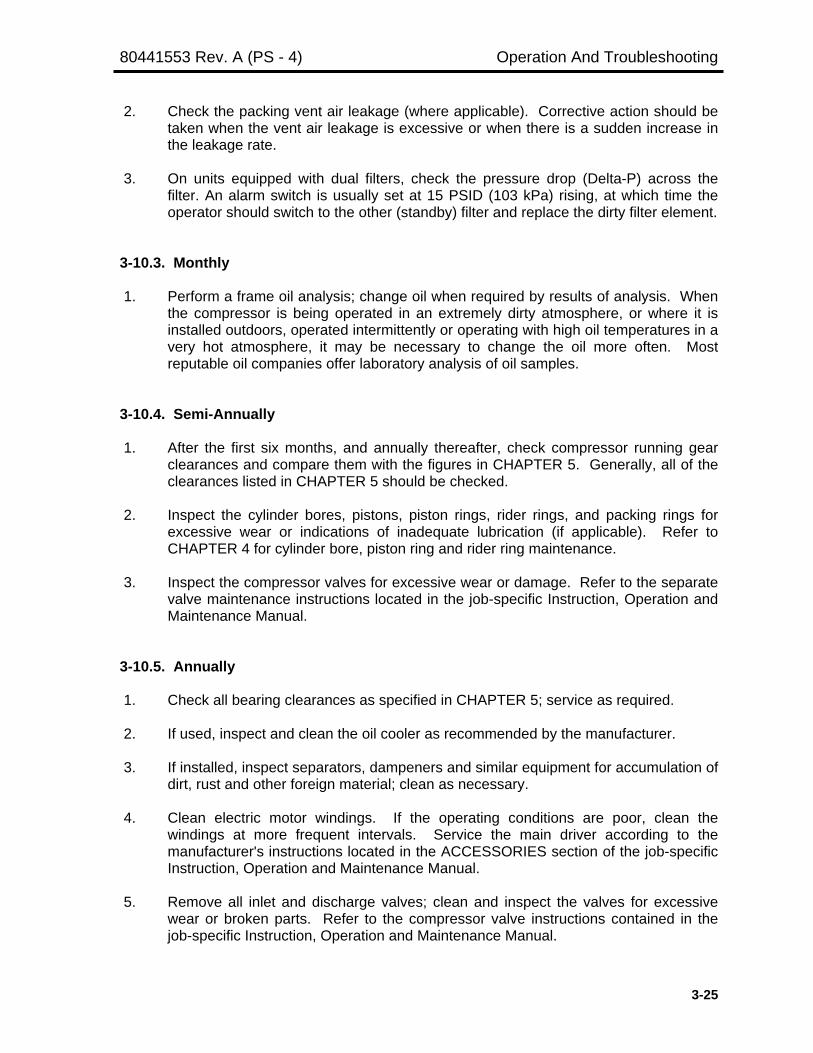
80441553 Rev. A (PS - 4) Operation And Troubleshooting
3-25
2. Check the packing vent air leakage (where applicable). Corrective action should betaken when the vent air leakage is excessive or when there is a sudden increase inthe leakage rate.
3. On units equipped with dual filters, check the pressure drop (Delta-P) across thefilter. An alarm switch is usually set at 15 PSID (103 kPa) rising, at which time theoperator should switch to the other (standby) filter and replace the dirty filter element.
3-10.3. Monthly
1. Perform a frame oil analysis; change oil when required by results of analysis. Whenthe compressor is being operated in an extremely dirty atmosphere, or where it isinstalled outdoors, operated intermittently or operating with high oil temperatures in avery hot atmosphere, it may be necessary to change the oil more often. Mostreputable oil companies offer laboratory analysis of oil samples.
3-10.4. Semi-Annually
1. After the first six months, and annually thereafter, check compressor running gearclearances and compare them with the figures in CHAPTER 5. Generally, all of theclearances listed in CHAPTER 5 should be checked.
2. Inspect the cylinder bores, pistons, piston rings, rider rings, and packing rings forexcessive wear or indications of inadequate lubrication (if applicable). Refer toCHAPTER 4 for cylinder bore, piston ring and rider ring maintenance.
3. Inspect the compressor valves for excessive wear or damage. Refer to the separatevalve maintenance instructions located in the job-specific Instruction, Operation andMaintenance Manual.
3-10.5. Annually
1. Check all bearing clearances as specified in CHAPTER 5; service as required.
2. If used, inspect and clean the oil cooler as recommended by the manufacturer.
3. If installed, inspect separators, dampeners and similar equipment for accumulation ofdirt, rust and other foreign material; clean as necessary.
4. Clean electric motor windings. If the operating conditions are poor, clean thewindings at more frequent intervals. Service the main driver according to themanufacturer's instructions located in the ACCESSORIES section of the job-specificInstruction, Operation and Maintenance Manual.
5. Remove all inlet and discharge valves; clean and inspect the valves for excessivewear or broken parts. Refer to the compressor valve instructions contained in thejob-specific Instruction, Operation and Maintenance Manual.

Operation And Troubleshooting 80441553 Rev. A (PS - 4)
3-26
6. Inspect cylinder inlet and discharge passages; remove any accumulation of foreignmaterial.
7. Inspect the cylinder water jackets and passages for scale and other deposits; cleanas required.
3-10.6. Periodically (As Dictated By Experience)
1. Change the oil filter cartridge (or filter elements).
2. Change or clean and service the air filter element.
3. Clean and service the mechanical lubricators, oil pumps and other accessoryequipment.
4. Clean the oil suction screen(s) in the frame oil sump. This is normally donewhenever the frame oil is changed.
5. Clean the frame breather.
6. Clean the sight glasses of all level gauges and flow indicators.
7. Check all oil scraper and piston rod packing rings for wear and leakage. Renew ifnecessary.
8. Check the piston-to-bore clearance and the piston rider rings for excessive wear.This is especially important on non-lubricated cylinders.
3-11. EXTENDED SHUTDOWN PRECAUTIONS
Conditions at the compressor site must be given careful consideration when thecompressor is to be removed from service for an extended period. The following procedureis generally recommended when the compressor may be shut down for up to three weeks.
NOTE
Additional measures may be required to protect the equipmentdepending on the length of shutdown and the localenvironmental conditions.
If possible, run the unit for 10 to 15 minutes each day with no load. An alternatemethod is to operate the auxiliary motor-driven oil pump (if supplied) and compressorcylinder lubricator (if applicable) for 10 to 15 minutes while manually barring the unit toensure complete oil distribution.
WARNINGCompressor cylinders must be depressurized toatmospheric pressure before barring. Compressor

80441553 Rev. A (PS - 4) Operation And Troubleshooting
3-27
pistons will move to bottom-dead-center as an equilibriumcondition due to the difference in piston surface area (bypiston rod cross sectional area) exposed to the system airpressure. Failure to depressurize the compressorcylinders prior to barring may result in unexpectedrollover that can cause personal injury.
WARNINGBefore barring the unit over, the operator must ensurethat the driver will not start by making sure that powercannot be turned on with electric motor driven units.Failure to heed this WARNING could result in a fatalaccident if the unit starts unexpectedly.
If the compressor shutdown is to exceed three weeks, the recommendations in thefollowing paragraphs should be observed to keep the cylinder in good condition. Refer tothe manufacturer's recommendations for the driver and other accessory equipment whenplanning an extended shutdown.
3-11.1. Non-Lubricated Cylinder
The primary damage to "NL" cylinder during long shutdowns is caused by rust.When the compressor is to be inoperative for an extended period, we recommend thefollowing measures be taken:
1. Drain the cylinder coolant jackets, if not protected by antifreeze.
WARNINGDe-pressurize the cylinder before removing the outerhead. Opening a pressurized cylinder or section of pipingwithout venting residual pressure can cause a violentrelease of air, the ejection of compressor parts and resultin severe personal injury or death.
2. Remove the cylinder outer head and frame end valves.
3. With a lint-free cloth, or sponge of synthetic material, wipe the cylinder dry of anycondensate. Move the piston so that the entire bore can be dried.
4. Pack the cylinder bore loosely with desiccant bags or volatile corrosion inhibitor (VCI)paper.
5. After the bore of the cylinder has been wiped dry and the desiccant bags or VCIpaper inserted, reinstall the outer head and the frame end valves.
6. To prevent circulation of air through the cylinder, which could cause rusting, blank offthe inlet and discharge passages. (Consideration should be given to placing a slight

Operation And Troubleshooting 80441553 Rev. A (PS - 4)
3-28
charge of dry nitrogen on the compressor cylinder.) If rust should form, remove itcompletely before the compressor is placed back into service. Rust will cause un-necessary wear of the piston and/or rider rings.
7. Before restarting the compressor, be sure to remove all desiccant bags or VCI paper,open the inlet and discharge passages, and thoroughly inspect cylinder internals.
3-12. TROUBLESHOOTING
Major trouble can usually be traced to long periods of operation with unsuitablecoolant or lubrication, careless operation and maintenance, operating the compressor on aservice for which it was not intended.
Lack of proper care for any machine will usually result in a succession of minortroubles and eventually can lead to a major breakdown. Minor trouble can normally beexpected at various times during the routine operation of the compressor; these troubles aremost often traced to process conditions, improper adjustments, or operators being unfamiliarwith the function of various compressor parts and systems. Difficulties of this type canusually be corrected by cleaning, proper adjustment, elimination of an adverse condition orquick replacement of a relatively minor part.
Troubleshooting is largely a process of elimination based on a thorough knowledgeof the interrelated functions of the various parts and the effects of adverse conditions. Acomplete list of possible troubles with their causes and corrections is impractical, but thefollowing list (Table 3-5) of the more frequently encountered troubles and their causes isoffered as a guide. You may wish to add to this list for your particular unit.
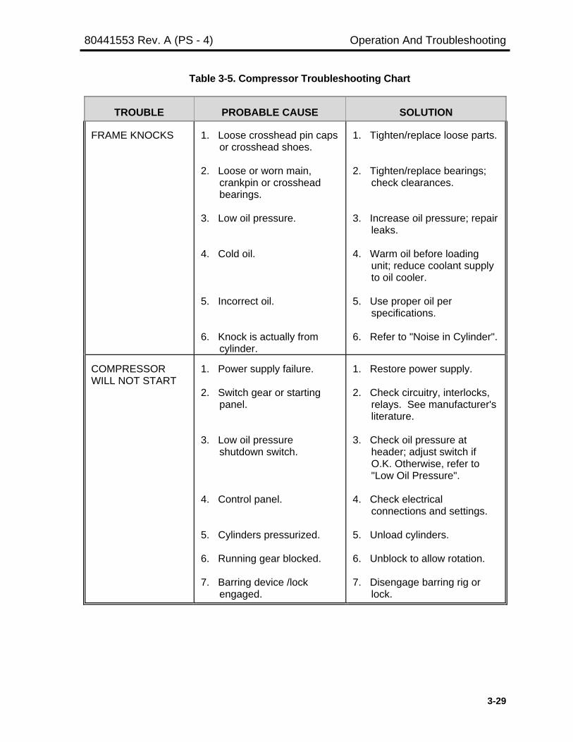
80441553 Rev. A (PS - 4) Operation And Troubleshooting
3-29
Table 3-5. Compressor Troubleshooting Chart
TROUBLE PROBABLE CAUSE SOLUTION
FRAME KNOCKS 1. Loose crosshead pin capsor crosshead shoes.
2. Loose or worn main,crankpin or crossheadbearings.
3. Low oil pressure.
4. Cold oil.
5. Incorrect oil.
6. Knock is actually fromcylinder.
1. Tighten/replace loose parts.
2. Tighten/replace bearings;check clearances.
3. Increase oil pressure; repairleaks.
4. Warm oil before loadingunit; reduce coolant supplyto oil cooler.
5. Use proper oil perspecifications.
6. Refer to "Noise in Cylinder".
COMPRESSORWILL NOT START
1. Power supply failure.
2. Switch gear or startingpanel.
3. Low oil pressureshutdown switch.
4. Control panel.
5. Cylinders pressurized.
6. Running gear blocked.
7. Barring device /lockengaged.
1. Restore power supply.
2. Check circuitry, interlocks,relays. See manufacturer'sliterature.
3. Check oil pressure atheader; adjust switch ifO.K. Otherwise, refer to"Low Oil Pressure".
4. Check electricalconnections and settings.
5. Unload cylinders.
6. Unblock to allow rotation.
7. Disengage barring rig orlock.
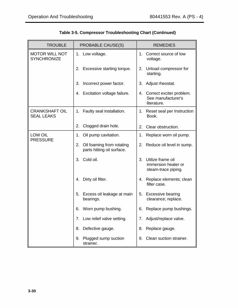
Operation And Troubleshooting 80441553 Rev. A (PS - 4)
3-30
Table 3-5. Compressor Troubleshooting Chart (Continued)
TROUBLE PROBABLE CAUSE(S) REMEDIES
MOTOR WILL NOTSYNCHRONIZE
1. Low voltage.
2. Excessive starting torque.
3. Incorrect power factor.
4. Excitation voltage failure.
1. Correct source of lowvoltage.
2. Unload compressor forstarting.
3. Adjust rheostat.
4. Correct exciter problem.See manufacturer'sliterature.
CRANKSHAFT OILSEAL LEAKS
1. Faulty seal installation.
2. Clogged drain hole.
1. Reset seal per InstructionBook.
2. Clear obstruction.
LOW OILPRESSURE
1. Oil pump cavitation.
2. Oil foaming from rotatingparts hitting oil surface.
3. Cold oil.
4. Dirty oil filter.
5. Excess oil leakage at mainbearings.
6. Worn pump bushing.
7. Low relief valve setting.
8. Defective gauge.
9. Plugged sump suctionstrainer.
1. Replace worn oil pump.
2. Reduce oil level in sump.
3. Utilize frame oilimmersion heater orsteam-trace piping.
4. Replace elements; cleanfilter case.
5. Excessive bearingclearance; replace.
6. Replace pump bushings.
7. Adjust/replace valve.
8. Replace gauge.
9. Clean suction strainer.

80441553 Rev. A (PS - 4) Operation And Troubleshooting
3-31
Table 3-5. Compressor Troubleshooting Chart (Continued)
TROUBLE PROBABLE CAUSE(S) REMEDIES
NOISE IN CYLINDER 1. Loose piston.
2. Piston hitting outer heador frame head.
3. Broken or leaking valve.
4. Piston rings broken.
5. Valve seat gasketdamaged or valve notseated.
6. Unloader plungerchattering.
1. Disassemble cylinder andtighten piston nut.
2. Adjust end clearance tospecifications.
3. Repair or replace valves.
4. Replace piston rings.
5. Replace gasket; checkseating surface fordamage and repair asnecessary.
6. Replace unloader plungerspring(s).
OIL SCRAPERLEAKAGE
1. Worn scraper rings.
2. Scraper rings incorrectlyassembled.
3. Worn or scored pistonrod.
4. Ring side clearanceexcessive.
1. Replace rings.
2. Assemble per instructionbook, section 4-16.
3. Replace piston rod.
4. Replace rings.
PACKINGOVERHEATING
1. Lubrication failure.
2. Improper lube oil or feedrate.
3. Insufficient cooling. (Especially with water-
cooled packing.)
4. Inadequate side clearance.
1. Replace lubrication checkvalve or lubricator pump.
2. Use correct oil; increasefeed rate.
3. Clean coolant passages,install water filter, increasesupply pressure or rate.Reduce coolanttemperature at inlet.
4. Replace packing rings.

Operation And Troubleshooting 80441553 Rev. A (PS - 4)
3-32
Table 3-5. Compressor Troubleshooting Chart (Continued)
TROUBLE PROBABLE CAUSE(S) REMEDIES
PACKING LEAKAGE 1. Worn packing rings.
2. Improper lube oil or lubeoil feed rate. (Piston rodturns blue hot in color.
3. Dirt in packing.
4. Gas pressure increasedtoo fast.
5. Rings incorrectlyassembled.
6. Improper end or sideclearance.
7. Packing vent plugged.
8. Scored piston rod.
9. Excessive rod runout.
1. Replace packing rings.
2. Use correct oil orincrease feed rate.
3. Clean packing, piping.
4. Reduce pressure andincrease at lower rate.
5. Reassemble perInstruction book section4-15.
6. Check and adjustclearances.
7. Unblock and providelow-point drains.
8. Replace piston rod.
9. Replace shoes. Ensurecrosshead jam nut issquare with crossheadnose.
EXCESSIVE CARBONON VALVES
1. Too much cylinder lubeoil.
2. Wrong cylinder lube oil,too light; high carbonresidue.
3. Oil carryover from inlet ofprevious stage.
4. Broken or leaking valves;high temperature.
5. Excessive pressure ratioacross cylinder; hightemperature.
1. Adjust supply rate.
2. Use correct oil for application.
3. Install separator/drainsystem.
4. Replace or repairvalves.
5. Clean intercoolers;valves. Look for failedvalve in adjacentcylinder, upstream ordownstream.

80441553 Rev. A (PS - 4) Operation And Troubleshooting
3-33
Table 3-5. Compressor Troubleshooting Chart (Continued)
TROUBLE PROBABLE CAUSE(S) REMEDIES
HIGH DISCHARGETEMPERATURE
1. Excessive ratio acrosscylinder.
2. Fouled intercooler orpiping.
3. Leaking dischargevalves or piston rings.
4. High inlet airtemperature.
5. Fouled cylinder waterjackets.
6. Improper cylinder lubeoil or lube feed rate.
1. Replace leaking inletvalves or piston rings.
2. Clean intercooler orpiping; reduce lubefeed rate.
3. Repair/replace parts asnecessary.
4. Clean intercooler;adjust coolantflow/temperature.
5. Clean water jackets.
6. Use correct lube oil andcorrect the feed rate.
RELIEF VALVE POPPING 1. Faulty relief valve.
2. Leaking inlet valves orpiston rings on nexthigher stage.
3. Obstruction, blindflange or valve closedin discharge line.
1. Test valve and resetper manufacturer'sinstructions.
2. Repair/replacedefective parts.
3. Relieve obstruction;open valve.

PET STAR 4CHAPTER 4
MAINTENANCEParagraph Page
4-1. GENERAL INFORMATION .............................................................................. 4-24-1.1. Stud Replacement ...................................................................................... 4-34-1.2. Stud Installation Using Anaerobic Adhesive ............................................... 4-34-2. SAFETY PRECAUTIONS ................................................................................ 4-44-3. FRAME ALIGNMENT........................................................................................ 4-54-3.1. Checking Foundation Bolt Tightness .......................................................... 4-64-4. FRAME OIL PUMP............................................................................................ 4-64-4.1. Removing The Main Oil Pump .................................................................... 4-94-4.2. Installing The Main Oil Pump ...................................................................... 4-104-5. FRAME BREATHER ........................................................................................ 4-124-6. CHANGING THE FRAME OIL ......................................................................... 4-124-7. DRIVE END COVER & CRANKSHAFT OIL SEAL .......................................... 4-134-7.1. Crankshaft Oil Ring and Oil Seal Removal ................................................. 4-154-7.2. Crankshaft Oil Ring and Oil Seal Installation .............................................. 4-154-8. CRANKSHAFT THRUST ................................................................................. 4-154-9. MAIN BEARINGS ............................................................................................. 4-164-9.1. Main Bearing Removal ............................................................................... 4-164-9.2. Main Bearing Installation ............................................................................ 4-174-10. CONNECTING RODS ...................................................................................... 4-184-10.1. Crankpin Bearings ...................................................................................... 4-204-10.2. Crosshead Pin Bushing .............................................................................. 4-224-11. CROSSHEAD ................................................................................................... 4-234-11.1. Replacing Crosshead Shoes ...................................................................... 4-234-12. COMPRESSOR CYLINDERS .......................................................................... 4-254-12.1. Removing The Outer Head ......................................................................... 4-264-12.2. Removing The Piston And Rod Assembly .................................................. 4-274-12.3. Disassembling The Piston And Rod ........................................................... 4-274-12.4. Inspecting The Cylinder Bore ..................................................................... 4-274-12.5. Removing The Cylinder .............................................................................. 4-294-12.6. Installing And Aligning The Cylinder ........................................................... 4-294-12.7. Assembling The Piston and Rod ................................................................ 4-304-12.8. Installing The Piston And Rod Assembly .................................................... 4-334-12.9. Installing The Outer Head .......................................................................... 4-354-13. PISTON END CLEARANCE ............................................................................ 4-354-14. PISTON ROD ALIGNMENT (RUNOUT) .......................................................... 4-364-14.1. Factors That Influence Piston Rod Runout ................................................. 4-374-14.2. Measuring Piston Rod Runout ................................................................... 4-374-15. PRESSURE PACKING .................................................................................... 4-394-16. OIL SCRAPPERS ............................................................................................ 4-434-17. V-BELT DRIVE ................................................................................................. 4-45
Maintenance 80441553 Rev. A (PS-4)
4-2
4-1. GENERAL INFORMATION
This chapter provides the recommended procedures for servicing the frame andrunning gear components, and cylinder components, except that valves and regulationdevices are covered by separate instructions in the job-specific Instruction, Operation andMaintenance Manual. A general description and illustration of the frame and running gearcomponents are located in CHAPTER 1.
NOTE
Maintenance instructions for accessory equipment (such asmotors, coolers) are furnished by the respectivemanufacturers. These instructions are located in theACCESSORIES section of the job-specific Instruction,Operation and Maintenance Manual.
Good working habits are essential to the performance of satisfactory maintenancework on the compressor. Since all frame maintenance is conducted through the top andside openings of the unit, it is essential that every precaution be taken to prevent dirt andother debris from entering the compressor. Cover exposed openings to keep dirt fromfalling into the frame interior. Scratches, nicks and burrs must be removed from machinedsurfaces prior to reassembly. This can be done using fine emery cloth, a fine hone or a millfile. (Do not use emery cloth, or any other finishing method employing abrasives, whenworking on soft bearing surfaces; such abrasive material can become embedded in thebearing metal.) To ensure reassembly in their original positions, most parts are stamped toidentify their original location. Mark or tag all other parts as they are disassembled so thatthey, too, can be reinstalled in their original location. Replace all composition gaskets thatare torn, dried or cracked.
Original parts should be thoroughly cleaned, inspected and measured for wear orother visible defects before re-using them, and except on NL cylinder parts or unlessotherwise stated, should be covered with a thin coating of clean lubricant beforereassembly.
WARNINGAir compressors require strict maintenance in order tooperate safely and efficiently. It must be understood thatthe compression of ANY gas is an inherently hazardousand all safety precautions given in this manual must befollowed. The proper tightening and periodic re-tighteningof nuts and bolts must be considered a top priorityroutine maintenance function. Failure to follow correctand safe maintenance practices can result in a seriouslife-threatening accident or damage to the equipment.
Always advance nuts in the tightening direction to align cotter pin openings once therequired torque or bolt stretch is obtained. Refer to CHAPTER 5, GENERAL DATA ANDCLEARANCES, for tightening requirements and torque specifications. Some fastenerlocations require a specific torque, and these are listed in Table 5-10 or 5-11, or in a

80441553 Rev. A (PS-4) Maintenance
4-3
supplement prepared for your compressor. All other fasteners are to be tightened to thetorque indicated in the standard torque table (Table 5-8 or 5-9), based on the fastener sizeand its usage (with or without a gasket, etc.). All fasteners must be tightened using acalibrated torque wrench or by stretch measurement; no other method is approved byIngersoll-Rand Company. The use of air-operated impact wrenches for finaltightening of fasteners shall be absolutely prohibited.
Lockwire must always be arranged so that it pulls on the bolt head or nut in thetightening direction. When reassembling, ensure that all locking devices are new and in-stalled properly to prevent loosening of parts during operation.
All clearances and fits listed in CHAPTER 5 should be checked during maintenancework involving those parts. Unless otherwise stated, these are for parts that are at roomtemperature and are generally referred to as "cold" clearances. Some slight changes in theclearances can be expected when the parts are at operating temperature. These arereferred to as "hot" clearances. It is recommended that running clearances be checked withthe parts in their assembled positions, wherever possible, since bearing crush, interferencefits and other factors can affect the clearance measurement.
4-1.1. Stud Replacement
Normal maintenance activities do not require removal and reinstallation of studs;they have been set with anaerobic adhesive at the factory and are not intended for removal.However, there may be instances where it is necessary to replace a damaged oroverstressed stud. The following procedure ‘Stud Installation Using Anaerobic Adhesive’ isrecommended:
4-1.2. Stud Installation Using Anaerobic Adhesive (Class 3A, ASTM A193, Grade B7/B7M)
This instruction describes the installation procedure for anaerobic set studs used inIngersoll-Rand PET Star 4 reciprocating compressors. Anaerobic set studs are bonded toa set depth with a threadlocking material that hardens when confined in the absence of airbetween close-fitting metal parts. Loctite® 262 anaerobic adhesive shall be used for allapplications, except pure oxygen and/or oxygen-rich applications. These applications willhave special procedures established for the type of anaerobic adhesive required.
Preparation: For best results, parts must be clean and dry. Grease, oil or protectivecoatings should be removed with approved safety solvents. Blow out stud holes withcompressed air to remove any metal chips or foreign material.
Application of Anaerobic Adhesive: Anaerobic adhesive can be applied directly from theapplicator and should be applied to the stud in sufficient quantity to fill all engaged threads.
Installation of Stud: Determine proper stud engagement based on stud diameter (see Table4-1). Measurements are to be made from the first thread. Chamfered portion is not to beincluded in the measurement. Install the stud by hand until fully engaged using a stud driveror other suitable method.
Cure Time: Studs must remain undisturbed for a minimum of ½ hour to achieve handlingstrength. Any jiggling, twisting or testing for handling strength before this time will not be of
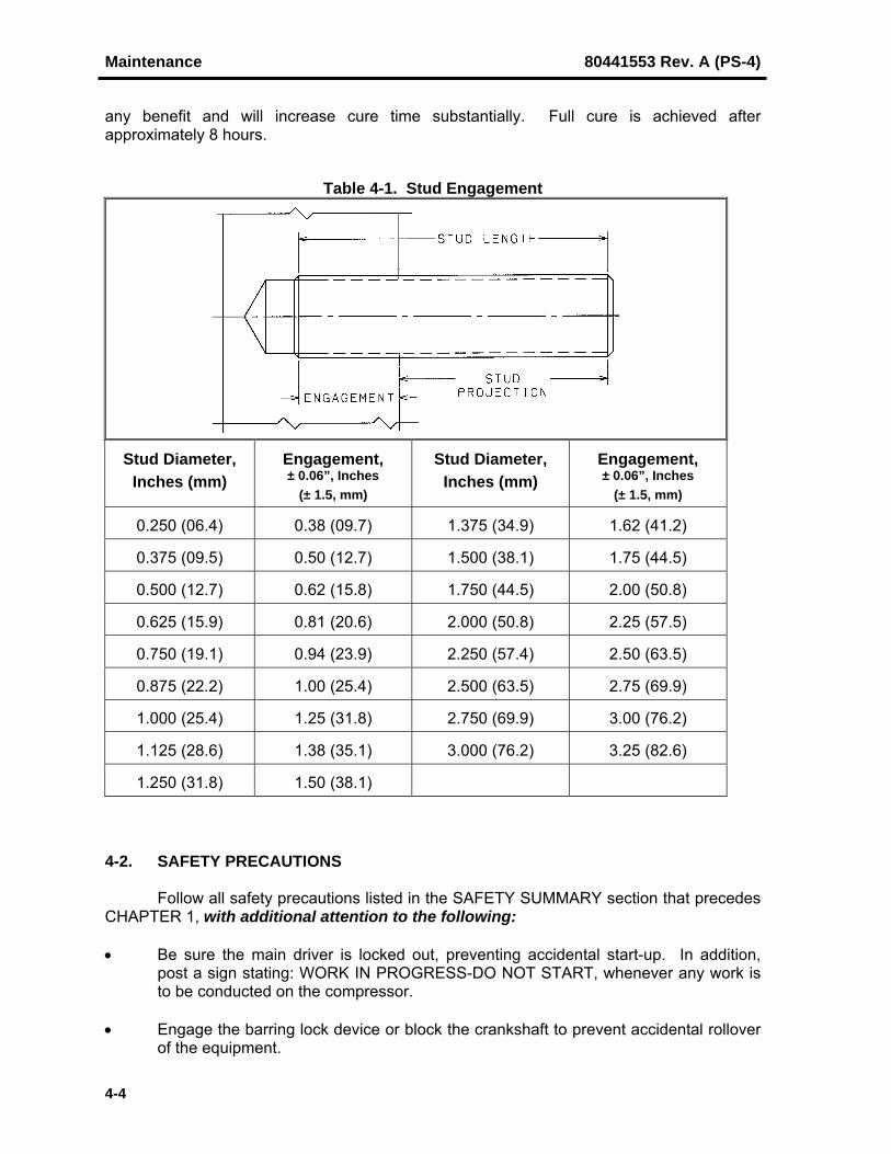
Maintenance 80441553 Rev. A (PS-4)
4-4
any benefit and will increase cure time substantially. Full cure is achieved afterapproximately 8 hours.
Table 4-1. Stud Engagement
Stud Diameter,Inches (mm)
Engagement,± 0.06”, Inches
(± 1.5, mm)
Stud Diameter,Inches (mm)
Engagement,± 0.06”, Inches
(± 1.5, mm)
0.250 (06.4) 0.38 (09.7) 1.375 (34.9) 1.62 (41.2)
0.375 (09.5) 0.50 (12.7) 1.500 (38.1) 1.75 (44.5)
0.500 (12.7) 0.62 (15.8) 1.750 (44.5) 2.00 (50.8)
0.625 (15.9) 0.81 (20.6) 2.000 (50.8) 2.25 (57.5)
0.750 (19.1) 0.94 (23.9) 2.250 (57.4) 2.50 (63.5)
0.875 (22.2) 1.00 (25.4) 2.500 (63.5) 2.75 (69.9)
1.000 (25.4) 1.25 (31.8) 2.750 (69.9) 3.00 (76.2)
1.125 (28.6) 1.38 (35.1) 3.000 (76.2) 3.25 (82.6)
1.250 (31.8) 1.50 (38.1)
4-2. SAFETY PRECAUTIONS
Follow all safety precautions listed in the SAFETY SUMMARY section that precedesCHAPTER 1, with additional attention to the following:
• Be sure the main driver is locked out, preventing accidental start-up. In addition,post a sign stating: WORK IN PROGRESS-DO NOT START, whenever any work isto be conducted on the compressor.
• Engage the barring lock device or block the crankshaft to prevent accidental rolloverof the equipment.

80441553 Rev. A (PS-4) Maintenance
4-5
• Service on the compressor should always start with cleaning the foundation andsurrounding area to remove oil, dirt or debris which could cause maintenancepersonnel to slip and fall.
• Close suction and discharge line valves, and bleed off any pressure between thecompressor and the shutoff valves. If extensive work is to be conducted on acylinder, when pressure exists upstream or downstream of the cylinders, makeabsolutely sure that blinds, double valves and bleeders are installed between thepressure containing piping or parts, and the equipment being serviced.
• Minor adjustments may be performed without installing blinds provided that adequateprecautions, such as de-pressurizing, are taken to protect personnel. Check valvesmust not be relied upon for isolating the compressor.
• Never open a compressor cylinder or any other part of the compression systemwithout completely relieving all pressures to atmosphere. Take all necessaryprecautions to prevent accidental re-pressurizing of the system.
• Precautionary measures specified by the Occupational Safety and Health Act of1970 (OSHA) must be complied with when storing, handling or using solvents.
• Volatile flammable liquids, such as alcohols, gasoline, kerosene, or naphtha must notbe used as cleaning agents for compressor parts. Use a suitable nonflammablesafety solvent approved for use on site. Thoroughly dry parts for reassembly.
Carbon tetrachloride, perchlorethylene, methylene chloride or methylethylketonemust NEVER be used as cleaning solvents. Strictly follow manufacturer's instructions whenusing any halogenated or organic solvents. THESE SOLVENTS ARE DANGEROUS. Mostsolvents of this type are now prohibited in the United States.
4-3. FRAME ALIGNMENT
Frame alignment can change due to a variety of reasons and therefore it is importantthat the alignment be checked on a regular basis so that corrective action can be takenbefore serious damage occurs. The same alignment checks made during installation shouldbe used and compared with the original installation data. Typical reasons for framemisalignment are:
1. Foundation distortion due to soil compacting under the mat.
2. Thermal humping due to the temperature differential between the top and bottom ofthe foundation block.
3. Cracking of the foundation block.
4. Compressor loose on grout, allowing fretting of the grout.
5. Grout and/or concrete deterioration due to impregnation of oil.
6. Incorrectly torqued foundation bolts.
Maintenance 80441553 Rev. A (PS-4)
4-6
4-3.1. Checking Foundation Bolt Tightness
The importance of properly tightening foundation bolts is critical in maintaining truealignment of the crankshaft and main bearing saddles. By measuring the amount of pull-down or pull-up of the frame foot, an indication of the foundation's condition can bedetermined and corrective action taken before serious damage to the bearings occur.
Before re-torquing any foundation bolt, it is recommended to take main bearingclearances. This will provide a record of the machine's condition prior to any necessarycorrective action, and will be of value when troubleshooting.
1. Collect the appropriate tools and material (torque wrench, socket, marking pen, anddial indicator with magnetic base).
2. Visually inspect the foundation and frame-to-soleplate/foundation joint line.
3. Determine the bolt size, correct torque value and the recommended lubricant. Referto CHAPTER 5, GENERAL DATA AND CLEARANCES.
4. Match mark the foundation bolt nut and frame foot (or stud). This temporaryreference mark will indicate an under- or over-torqued nut during re-torquing.
5. Mount the dial indicator magnetic base on the frame foot. Position the dial indicatorto indicate off the sole plate and/or foundation. Zero the indicator and check for asolid and fixed position of the magnetic base.
6. Loosen the foundation bolt nut and observe the dial indicator for any movement.Maximum allowable pull-up or pull-down is 0.0015 inch (0.038 mm).
7. Remove the foundation bolt nut and make sure the bolt threads are clean and free ofdirt, debris and burrs.
8. Apply the recommended lubricant to the bolt threads and nut face. Foundation boltnuts should turn freely by hand over the full length of thread.
9. Torque the foundation bolt nut to the specified value and observe the dial indicatorfor any movement. Any further rotation (past original match mark) or pull-down inexcess of 0.0015 inch (0.038 mm) must be noted and the condition investigated.
4-4. FRAME OIL PUMP
A shaft-driven, gear-type frame oil pump (Figure 4-1) is fitted to the end of thecompressor frame opposite the flywheel. The pump is directly driven by a hub oil pump thatis bolted onto the oil pump shaft. The hub oil pump is driven by a pressed in dowel pinlocated in the end of the crankshaft.
It is normally not necessary to disassemble the pump body itself, as the internal partsrarely require maintenance. However, in the event the pump needs to be removed orreplaced, use the following procedures:

80441553 Rev. A (PS-4) Maintenance
4-7
Figure 4-1. Frame Oil Pump & Cover Assembly
1. Cover Pump End2. Gasket Frame End3. Capscrew4. Stud5. Nut6. Pin Roll7. Oil Pump & Cover8. Bolt Hex9. O-ring10. Rotation Nameplate11. Drivescrew

Maintenance 80441553 Rev. A (PS-4)
4-8Figure 4-2. Frame Oil Pump Assembly
1.
Ada
pter
Hou
sing
2.
Rin
g E
ccen
tric
3.
Pla
te W
eaer
& S
top
4.
Cov
er O
il P
ump
End
5.
O-r
ing
6.
Sea
l Oil
Pum
p S
haft
7.
Sha
ft M
ain
Oil
Pum
p8.
C
apsc
rew
9.
Thre
adse
al10
. W
ashe
r11
. G
eror
otor
12.
Key
squ
are
13.
Bea
ring
Thru
st14
. C
over
Lub
ricat
or15
. C
apsc
rew
16.
Sea
lant
Gas
ket
17.
Hub
oil
pum
p18
. S
etsc
rew
19.
Key
squ
are

80441553 Rev. A (PS-4) Maintenance
4-9
4-4.1. Removing the Main Oil Pump
1. First drain the oil from the compressor. Then disconnect the oil pump suction anddischarge piping as shown in Figure 4-3. Loosen the capscrews that fasten thesuction pipe to the frame and disconnect the threaded joint to oil pump. Bump thesuction pipe connection to free the gaskets. Use care here, because the oil pump isa made of a cast iron stick and it can be broken if abused.
Figure 4-3. Oil Pump Location on Frame
2. Loosen the capscrews that fasten the discharge pipe to the frame and disconnect thethreaded joint to oil pump and from wherever it is convenient to separate the pipefrom the cooler. Support the oil cooler piping first if required then bump thedischarge pipe to free the gaskets.
NOTE
When the pump is removed, it must be removed in conjunctionwith the frame pump cover. This must be done before workcan be done on the oil pump drive hub.
3. Rig the suction piping assembly and remove. Then rig the discharge piping

Maintenance 80441553 Rev. A (PS-4)
4-10
assembly and remove. Finally attach a sling from an overhead hoist to support thepump and frame pump cover assembly when it is unbolted.
4. Remove the seven capscrews (#3) Figure 4-1, along with the nuts (#5) from thestuds (#4).
5. Remove the top plate cover (See Figure 4-3) that allows access to the oil pumpdrive.
CAUTIONWhen pulling the oil pump and frame pump cover awayfrom the frame, be careful not to move the oil pump up ordown or left to right until the oil pump drive hub is clear ofthe dowel pin.
6. Pull the oil pump and frame pump cover with its protruding drive shaft and hub oilpump (#17) Figure 4-2 straight away from the compressor.
7. Move the pump and frame pump cover assembly to a clean work area. Take carethat the protruding drive shaft and hub oil pump is not bent or damaged in theprocess.
8. The hub oil pump (#17) Figure 4-2 is now accessible for service.
WARNINGWhen removing the hub oil pump (#17) Figure 4-2 from theoil pump shaft, ensure it is supported to prevent it fromfalling when it comes free. Failure to follow this warningmay result in personal injury.
9. Remove the setscrew from the hub oil pump (#17) Figure 4-2. Loosen it until the huboil pump loosens on the pump drive shaft.
10. Remove the hub oil pump (#17) Figure 4-2 from the lube oil pump drive shaft.
11. Remove the capscrews (#8) Figure 4-1 that fasten the pump to the frame pumpcover (#1) Figure 4-1. Bump the pump loose from the frame pump cover and pull itstraight away from the frame pump cover.
4-4.2. Installing the Main Oil Pump
1. Replace all O-rings and gaskets with new ones when reassembling.
2. Place the new O-ring (#9) Figure 4-1 on the pump drive shaft housing. Clean thebore in the frame pump cover and remove any burrs, gouges and/or nicks.

80441553 Rev. A (PS-4) Maintenance
4-11
3. Use a hoist and sling to support the pump as it is moved into position to attach. Takecare that the protruding drive shaft is not bent or damaged in the process.
4. When fitted properly, attach the oil pump (#7) to the frame pump cover (#1) andsecure with eight capscrews (#8) Figure 4-1. Use Loctite® 242 on the capscrewthreads. Torque evenly as specified in CHAPTER 5, General Data.
5. Loosely fit the hub oil pump (#17) Figure 4-2 on to the pump shaft.
6. Install the setscrew but do not tighten.
7. Place the square key (#19) Figure 4-2 into the oil pump drive shaft.
8. Align the hub oil pump keyway with the installed key and tighten the setscrew,drawing the hub oil pump onto the shaft.
9. Rig the oil pump and frame pump cover assembly for lifting. Install a new gasket(#2) on the frame pump cover (#1) Figure 4-1.
CAUTIONWhen putting the oil pump into the frame, be careful whenmoving the oil pump up or down or left to right to be surethe hub oil pump enters smoothly. Once entry begins, ifnecessary make only small, precise adjustments to avoiddamaging the coupling.
NOTE
When the pump is installed, it must be installed in conjunctionwith the frame pump cover (#1) Figure 4-1. This must be doneafter work on the pump is completed or the pump is replaced.
10. Carefully lift the oil pump and frame pump cover with its protruding drive shaft andhub oil pump (#17) Figure 4-2. Carefully adjust its position, so no damage is done tothe pump drive shaft, until the hub oil pump hub is fitted onto the dowel pin on thecrankshaft and the cover studs (#4) Figure 4-1.
11. Start the nuts (#5) Figure 4-1 on the studs to keep the cover in place.
12. Start the seven capscrews (#3) Figure 4-1. Torque the capscrews and nuts evenly asspecified in CHAPTER 5, General Data.
13. Remove the support rigging from the oil pump and frame pump cover.
WARNINGCompressor cylinders must be depressurized toatmospheric pressure before barring. Compressorpistons will move to bottom-dead-center as an equilibriumcondition due to the difference in piston surface area (by

Maintenance 80441553 Rev. A (PS-4)
4-12
piston rod cross sectional area) exposed to the system airpressure. Failure to depressurize the compressorcylinders prior to barring may result in unexpectedrollover that can cause personal injury.
WARNINGBefore barring the unit over, the operator must ensurethat the driver will not start by locking out and tagging outequipment, making sure that power cannot be turned onaccidentally. Failure to heed this WARNING could resultin a fatal accident if the unit starts over unexpectedly.
14. Bar the compressor over to make sure the oil pump is running freely and notjammed. If clear, rig the discharge and inlet piping assembly for lifting andinstallation. Reconnect the pump suction and discharge piping along with the topplate cover using new gaskets on all connections that were disconnected. If oilpump is not clear, install a new oil pump.
4-5. FRAME BREATHER
1. Examine the breather element at regular intervals and service it as required.
2. Clean the element by washing it thoroughly in a nonflammable solvent. Allow thefilter to air dry, then apply oil to the filter before reinstalling it in the breather cap.
4-6. CHANGING THE FRAME OIL
The method of completely draining oil from the frame lubricating system will varybetween each installation because of piping configurations. However, the followingprocedure can be used as a guide for most compressors equipped with an auxiliary oilpump. Refer to Figure 4-3 for connections.
Ingersoll-Rand recommends that the frame oil and oil filter cartridge be changed afterthe initial 24 to 72 hours of operation for a new or overhauled unit. Thereafter, it should notbe necessary to change the oil more often than every 4000 to 8000 hours, depending on thelocal operating conditions and as determined by monthly oil analysis. When the compressoris operated intermittently, or where the oil reaches high temperatures in a very hotatmosphere, it may be necessary to change the oil more often.
1. The best oil temperature for completely draining the lubricating system is between120º and 150º F (48º and 65º C). Operate the auxiliary motor-driven oil pump inconjunction with the frame oil heater to circulate the oil while it is being heated.Continue to run the auxiliary motor-driven oil pump during the following drain andflush operation.

80441553 Rev. A (PS-4) Maintenance
4-13
CAUTIONMake sure the frame oil heater is de-energized beforedraining the frame oil. Failure to do so can result in theheater element burning out.
2. Connect a hose to drain that is long enough to reach to each end of the compressorframe; then, install a valve and a three-foot length of pipe in the free end of the hose.Remove the covers from the frame to gain access to the frame interior. Starting atthe driver end (using the hose and pipe nozzle connected into the lubricating systemat the drain), and with the auxiliary oil pump running, wash the frame interior todislodge debris and residue from the sides and corners of the frame. Then agitatethe oil in the bottom of the sump to assist in the removal of all foreign particles in theframe sump.
3. Stop the pump and completely drain the system from the oil cooler, filters and sump.Remove hoses used to assist in the draining and flushing procedure.
4. Service the oil filter(s) and install new filter.
5. When changing the lubricating oil, the oil strainer on the end of the pump suctionpipe must be cleaned. The frame interior should be thoroughly wiped out to removepuddles of the old oil and any accumulation of dirt or debris on the walls of the framesump using clean, lint-free rags, NOT waste or lint rags. Use a light to examinecorners, pockets and other areas where dirt might lodge. The inside of the framehas been painted to facilitate the examination for dirt; DO NOT scrub or sand off thisoil-proof paint when cleaning the frame interior.
6. Close all the drain valves in the sump and cooler. Reconnect any piping that wasdisconnected.
7. Refill the system with new oil through the fill connector on the oil pump end of theframe. When sufficient oil has been added to cover the oil pump suction, start theauxiliary oil pump to completely fill the external system and vent any trapped air.Add oil to the system until the oil level is centered in the oil level gauge glass.Approximate oil capacity is listed in CHAPTER 3, Operation.
8. Reinstall all frame covers.
4-7. DRIVE END COVER & CRANKSHAFT OIL SEAL
The drive end cover and crankshaft oil seal assembly is located at the drive end ofthe compressor to prevent oil leakage where the crankshaft extends through the frame driveend cover. The crankshaft oil seal arrangement shown in Figure 4-4 consists of acrankshaft oil ring clamped around the crankshaft, a retaining ring and a shaft seal. Thecrankshaft oil ring acts as a weather seal.
The oil seal should require little or no maintenance after proper initial installation. Ifleakage occurs, replace the oil seal as follows:

Maintenance 80441553 Rev. A (PS-4)
4-14
WARNINGCompressor cylinders must be depressurized toatmospheric pressure before barring. Compressorpistons will move to bottom-dead-center as an equilibriumcondition due to the difference in piston surface area (bypiston rod cross sectional area) exposed to the system airpressure. Failure to depressurize the compressorcylinders prior to barring may result in unexpectedrollover that can cause personal injury.
WARNINGBefore barring the unit over, the operator must ensurethat the driver will not start by locking out and tagging outequipment, making sure that power cannot be turned onaccidentally. Failure to heed this WARNING could resultin a fatal accident if the unit starts over unexpectedly.
Figure 4-4. Drive End Cover & Crankshaft Oil Seal Assembly

80441553 Rev. A (PS-4) Maintenance
4-15
4-7.1. Crankshaft Oil Ring and Oil Seal Removal
1. Bar the compressor positioning the crankshaft oil ring (#2) to allow access to thesocket head capscrews (#3).
2. Remove the capscrews (#3) and lift both halves of the crankshaft oil ring off of thecrankshaft.
3. Remove the flathead capscrews (#25) from the retaining ring (#24) and lift bothhalves of the retaining ring from the end cover (#18).
4. Pry out the shaft seal (#23) and discard.
5. Examine the sealing surfaces of the drive end cover for corrosion and possibledamage that could prevent proper sealing between the shaft seal and drive endcover. Clean as required.
4-7.2. Crankshaft Oil Ring and Oil Seal Installation
1. Push the crankshaft toward the oil pump until all thrust clearance has been removed.
2. Insert the new oil seal (#23). (Ensure the lip of the seal is toward the crankcase andthe split/seam located at the top.) The ends of the seal should be glued togetherusing an adhesive.
3. Clean the threads of the retaining ring mounting screws (#25) and the sealingsurfaces of the retaining ring (#24). Then apply Loctite® 242 Anaerobic Sealant (orequivalent) to the threads.
4. Attach the retaining ring (#24) to the drive end cover (#18) with capscrews (#25).
5. Assemble the crankshaft oil ring (#2) around the crankshaft. Fasten loosely withcapscrews (#3).
6. Push the oil ring up against the drive end cover, then pull away 0.06 inch (1.5 mm).
7. Hold the oil ring in the position noted above and uniformly tighten the capscrews tosecure the oil ring to the end cover.
4-8. CRANKSHAFT THRUST
The two main bearing caps, located at the drive end, are supplied with bronze thrustshoes. The function of these shoes is to permit axial (lengthwise) positioning of thecrankshaft within the frame; they are not used to adjust thrust. The compressor drive trainwill control axial position of the crankshaft during operation.
Any thrust imparted to the thrust shoes by the crankshaft is originated by the drivetrain. The only internal compressor adjustment that can be made to compensate for this is tomove the main bearing cap in the same direction as the thrust. The amount that the capcan be moved is limited to one-half the tolerance between the main bearing cap bolts and

Maintenance 80441553 Rev. A (PS-4)
4-16
the bolt holes through the cap. In some cases, shims may be installed behind the thrustshoes. If this is the case, shim thickness can be adjusted accordingly.
4-9. MAIN BEARINGS
The main bearings consist of top and bottom shells that fit into machined bores in themain bearing caps and frame. The main bearings are located by raised tangs located atone of the split lines in the bearing shells and by the corresponding machined grooves inboth the frame and main bearing cap. Main bearings are precision-type (shimless) sized tothe correct running clearance and therefore require no fitting or shimming.
The main bearing caps are match marked to the frame. Whenever a main bearingcap is removed, it is important that it is returned to its original location in the frame. Alwayscheck the stamping on a bearing cap when installing it to be sure that it matches thestamping on the frame.
The bearings are made of steel backed up with bronze with a very thin babbittoverlay. DO NOT attempt to scrape or file the babbitt lining nor attempt to build up the endsof these bearing shells. The special self-fit surface on new bearing shells will quicklyconform to the crankshaft journal and load distribution when the unit is started. Thediametral journal-to-bearing running clearance will normally increase about 0.001 inch(0.025 mm) due to the self-fitting feature of the shells.
Improper bearing-to-shaft clearance can lead to one of two problems: (1) If thebearing clearance is too small, insufficient oil film thickness will result allowing heat buildupand metal-to-metal contact; (2) If the bearing clearance to too large, oil pressure will fall,failing to adequately lubricate the bearing surface.
4-9.1. Main Bearing Removal
1. Unbolt and remove the frame top cover(s) and gasket(s) above the main bearing(s).
2. Loosen and remove one of the tie rod cap nuts that is above the main bearing(s)being replaced, then pull the tie rod(s) from the frame. Bump out (using a brass baror lead hammer) the spacer bar. The spacer bar has a an interference fit within theframe.
3. If applicable, unscrew the thermocouple or RTD connector from the main bearingcap and disconnect the tubing from the coupling where it enters the frame.
4. Remove the main bearing cap stud nuts. The bearing cap has a 0.001 to 0.003 inch(0.025 to 0.08 mm) interference with the frame. If supplied, thread the main bearingcap lifting tool into the top of the cap to assist in removal. Carefully lift out the capusing an overhead hoist while tapping it lightly with a soft (lead or bronze) hammer.The bearing cap and top shell can then be removed.
5. Insert a roll-out tool which projects far enough out of the oil hole to bear on the edgeof the shell as shown in Figure 4-5. Then rotate the crankshaft slowly in the requireddirection to force the bottom shell out of its saddle in the frame.
6. Wipe the saddle, crankshaft journal and main bearing cap with clean lint-free rags.New bearing shells must fit the saddle and bearing cap perfectly so that they will be

80441553 Rev. A (PS-4) Maintenance
4-17
uniformly supported at all points. An imperfect fit caused by burrs, nicks, or dirtbetween the shells and saddle or cap will result in stress concentration and probablepremature failure of the bearing (caused by flexing of the shell).
CAUTIONThe preferred method for removing the lower bearingshell is to sling the crankshaft to an overhead hoist andlift the crankshaft slightly so that the bearing can be rolledout by hand. If a hydraulic jack is used, make sure thejack is supported by wooden blocking across the entirewidth of the frame. Failure to adequately support the jackand distribute the loading can force the jack through thebottom of the frame. Mount a dial indicator on thecrankshaft to observe the amount of movement relative tothe frame. It is only necessary to raise the crankshaftuntil the lower bearing shell is loose. The crankshaftshould never be raised more than the recommended topclearance (0.006 inch or 0.15 mm) unless all main bearingcaps have been removed.
TP-5009
Figure 4-5. Main Bearing Installation/Removal
4-9.2. Main Bearing Installation
The main bearings used on PET Star 4 compressors are precision made. Thebearings are inspected for conformance to all dimensions, including crush, before they aredelivered. Bearing crush (or draw) is the difference in height between the bearing and itshousing at the parting line. This crush is actually an interference fit between the bearing andit’s housing to prevent flexing of the bearing shell and to aid in transferring heat from thebearing. It is generally not necessary nor recommended to recheck bearing crush atassembly. If a bearing crush problem is suspected, contact Ingersoll-Rand.

Maintenance 80441553 Rev. A (PS-4)
4-18
1. Wash off any dirt or rust preventative from the new bearings with a safety solvent.Do not scrape the bearing or remove any metallic flashing that may be applied to thebearing faces. Apply clean lube oil to the journal and bearing faces only.
NOTE
The bearings shells must be inserted with the locating tang inthe correct position and the bearing end without the tang mustbe inserted first when installing new bearings.
2. Start with the bottom shell by placing it into the bearing cap as shown in Figure 4-6,with the roll-out tool inserted into the oil hole in position against the shell.
3. Slowly rotate the crankshaft until the shell is located in its saddle. If resistance is felt,sling or jack up on the crankshaft to provide additional clearance. Align the shellboth horizontally (side-to-side) and vertically (the ends must be flush with the saddle)in the saddle. Remove the bearing cap and lower the crankshaft (if applicable).
4. Apply anti-seize to the ends of the main bearing cap, then install the upper bearingshell into the cap and lower the cap over the journal. The cap has a 0.001 - 0.003inch (0.025 - 0.08 mm) interference with the frame. (Main bearing caps are matchmarked to the frame and must be reinstalled as indicated.)
5. Reinstall and torque the main bearing cap stud nuts two at a time, following adiagonal sequence, as specified in CHAPTER 5, GENERAL DATA ANDCLEARANCES.
6. If applicable, reinstall the thermocouple or RTD to the main bearing cap andreconnect the tubing.
7. Apply anti-seize lubricant to the ends of the spacer, then install the spacer into theframe. Spacers have a 0.004 - 0.006 inch (0.10 - 0.15 mm) interference with theframe. (Spacers are match stamped to the frame and must be reinstalled asindicated.)
8. Insert the tie rod through the frame and spacer. Apply anti-seize lubricant to the tierod washer and nut face. Install and tighten the tie rod until the frame is pulled up towithin 0.001 inch (0.025 mm) of the dimension stamped near the end of each spaceron the frame top. Check this dimension with an inside micrometer while tightening.
9. Reinstall the frame top cover(s) and gasket(s).
4-10. CONNECTING RODS
The connecting rods incorporate a full floating bronze crosshead bushing containedin the small end (eye) of the rod and two-piece, shell-type, full floating aluminum bearings inthe crankpin end of the connecting rod. The connecting rods are drilled from the crankpinbearing end to the bushing end to carry lubricating oil to the pin bushing and crosshead pin.If the bearing clearances become excessive or otherwise noisy, they should be replaced. Itis not necessary to remove the connecting rods to change the crankpin bearings.

80441553 Rev. A (PS-4) Maintenance
4-19
If it is necessary to remove the connecting rod from the unit, the following steps arerecommended:
1. Lock out and tag the driver starting equipment with a sign “WORK IN PROGRESSDO NOT START”.
2. Remove the top cover from the compressor frame.
3. Rotate the crankshaft to place the connecting rod in a convenient position to removethe cap bolts.
4. Be sure the connecting rod is well supported before continuing with the followingsteps.
5. Disconnect the connecting rod from the crankshaft according to the instructionsgiven in section 4-10.1
6. Remove the crosshead pin according to the instructions given in section 4-10.2
WARNINGCompressor cylinders must be depressurized toatmospheric pressure before beginning work.Compressor pistons will move to bottom-dead-center asan equilibrium condition due to the difference in pistonsurface area (by piston rod cross sectional area) exposedto the system air pressure. Failure to depressurize thecompressor cylinders prior to barring may result inunexpected rollover that can cause personal injury.
WARNINGBefore beginning work, the operator must ensure that thedriver will not start by locking out and tagging outequipment, making sure that power cannot be turned onaccidentally. Failure to heed this WARNING could resultin a fatal accident if the unit starts unexpectedly.
CAUTIONProtect the crosshead guide and crankpin to preventdamage to these finished surfaces.
7. Reposition the crankshaft as required so that it will provide the least interference withremoval of the rod.
8. Keeping the connecting rod well supported at all times, carefully remove it throughthe top opening in the frame.

Maintenance 80441553 Rev. A (PS-4)
4-20
The bushing to pin clearance can be checked with feelers or by comparingmicrometer measurements of the pin and bushing diameters. The bushing is non-adjustable;it must be replaced with a new one when the clearance becomes excessive or the bushingis otherwise defective. Refer to CHAPTER 5, GENERAL DATA AND CLEARANCES for acomplete list of assembly fits and clearances.
Install the connecting rod in the compressor using the reverse of the removalprocedure. Be sure the rifle drilled oil passage in the rod is clear of any obstruction beforeinstalling the rod. Refer to the appropriate instructions when assembling the rod on thecrankshaft and when installing the crosshead pin.
If new parts are being used, check for sufficient side clearance between theconnecting rod and adjacent crank webs. This clearance can be measured with feelers andcompared with the listed assembly clearance limits. As a final check of proper connectingrod installation, it is suggested that the unit be turned through one or more completerevolutions while watching the connecting rod to see that it runs true on the crankpin.Reinstall the top cover on the frame.
4-10.1. CRANKPIN BEARINGS
The crankpin bearings are two-piece, shell type, full-floating aluminum bearings toallow assembly on the crankpin (see Figure 4-6). These are precision bearings that requireno adjustment. If the bearing-to-shaft clearance becomes excessive and the bearings arenoisy, they can be replaced as follows. It is not necessary to remove the connecting rods tochange the crankpin bearings.
WARNINGCompressor cylinders must be depressurized toatmospheric pressure before beginning work.Compressor pistons will move to bottom-dead-center asan equilibrium condition due to the difference in pistonsurface area (by piston rod cross sectional area) exposedto the process gas pressure. Failure to depressurize thecompressor cylinders prior to barring may result inunexpected rollover that can cause personal injury.
WARNINGBefore beginning work, the operator must ensure that thedriver will not start by locking out and tagging outequipment, making sure that power cannot be turned onaccidentally. Failure to heed this WARNING could resultin a fatal accident if the unit starts unexpectedly.
1. Lock out and tag the driver starting equipment with a sign "WORK IN PROGRESS -DO NOT START".
2. Remove the frame top cover(s).
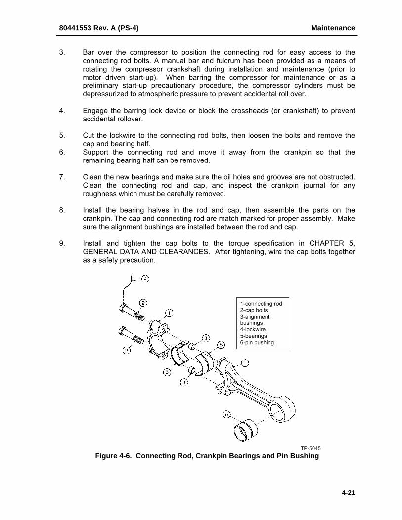
80441553 Rev. A (PS-4) Maintenance
4-21
3. Bar over the compressor to position the connecting rod for easy access to theconnecting rod bolts. A manual bar and fulcrum has been provided as a means ofrotating the compressor crankshaft during installation and maintenance (prior tomotor driven start-up). When barring the compressor for maintenance or as apreliminary start-up precautionary procedure, the compressor cylinders must bedepressurized to atmospheric pressure to prevent accidental roll over.
4. Engage the barring lock device or block the crossheads (or crankshaft) to preventaccidental rollover.
5. Cut the lockwire to the connecting rod bolts, then loosen the bolts and remove thecap and bearing half.
6. Support the connecting rod and move it away from the crankpin so that theremaining bearing half can be removed.
7. Clean the new bearings and make sure the oil holes and grooves are not obstructed.Clean the connecting rod and cap, and inspect the crankpin journal for anyroughness which must be carefully removed.
8. Install the bearing halves in the rod and cap, then assemble the parts on thecrankpin. The cap and connecting rod are match marked for proper assembly. Makesure the alignment bushings are installed between the rod and cap.
9. Install and tighten the cap bolts to the torque specification in CHAPTER 5,GENERAL DATA AND CLEARANCES. After tightening, wire the cap bolts togetheras a safety precaution.
1-connecting rod2-cap bolts3-alignmentbushings4-lockwire5-bearings6-pin bushing
TP-5045Figure 4-6. Connecting Rod, Crankpin Bearings and Pin Bushing
Maintenance 80441553 Rev. A (PS-4)
4-22
10. Remove all tools and any blocking, then bar over the compressor to check for properassembly.
11. Reinstall the frame top cover(s).
4-10.2. CROSSHEAD PIN BUSHING
The crosshead pin bushing is a one-piece, full-floating bronze bushing (see Figure 4-6). Access to the crosshead for pin and/or bushing replacement is gained by removing theside covers from the frame extension/crosshead guide.
WARNINGCompressor cylinders must be depressurized toatmospheric pressure before beginning work.Compressor pistons will move to bottom-dead-center asan equilibrium condition due to the difference in pistonsurface area (by piston rod cross sectional area) exposedto the system air pressure. Failure to depressurize thecompressor cylinders prior to barring may result inunexpected rollover that can cause personal injury.
WARNINGBefore beginning work, the operator must ensure that thedriver will not start by locking out and tagging outequipment, making sure that power cannot be turned onaccidentally. Failure to heed this WARNING could resultin a fatal accident if the unit starts unexpectedly.
1. Lock out and tag the driver starting equipment with a sign "WORK IN PROGRESS -DO NOT START". Block the crosshead and/or crankshaft to prevent furthermovement.
2. The crosshead pin is held in the crosshead by two, spiral type retainer rings locatedat both ends of the pin. Bar over the compressor to position the crosshead asrequired to gain access to these rings and then remove the ring from one end of thepin. This type retainer ring is removed by first prying one end out of the pin grooveand then unwinding the ring from the groove. A manual bar and fulcrum has beenprovided as a means of rotating the compressor crankshaft during installation andmaintenance (prior to motor driven start-up). When barring the compressor formaintenance or as a preliminary start-up precautionary procedure, the compressorcylinders must be depressurized to atmospheric pressure to prevent accidental rollover.
3. Block under connecting rod, then slide the pin out of the crosshead. If the pin is"frozen" in the crosshead, it may be necessary to attach a puller. If this happens,remove the pipe plug from one end of the pin and attach the puller into the pipe plugthreads.
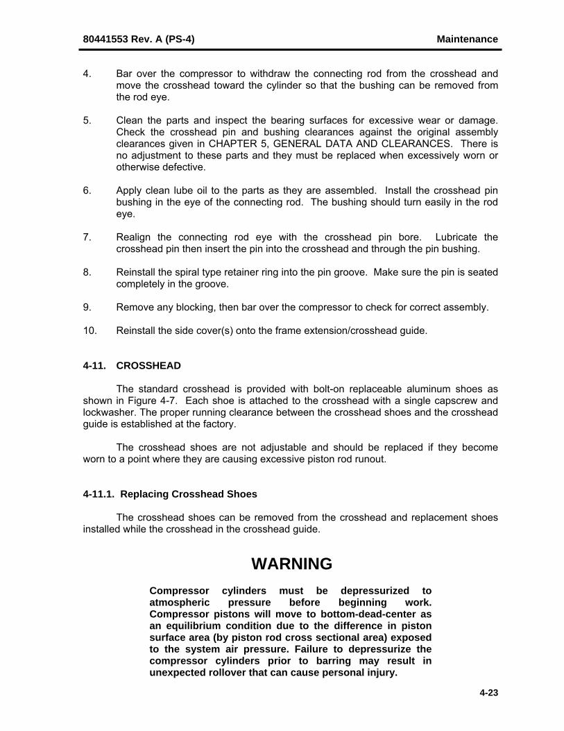
80441553 Rev. A (PS-4) Maintenance
4-23
4. Bar over the compressor to withdraw the connecting rod from the crosshead andmove the crosshead toward the cylinder so that the bushing can be removed fromthe rod eye.
5. Clean the parts and inspect the bearing surfaces for excessive wear or damage.Check the crosshead pin and bushing clearances against the original assemblyclearances given in CHAPTER 5, GENERAL DATA AND CLEARANCES. There isno adjustment to these parts and they must be replaced when excessively worn orotherwise defective.
6. Apply clean lube oil to the parts as they are assembled. Install the crosshead pinbushing in the eye of the connecting rod. The bushing should turn easily in the rodeye.
7. Realign the connecting rod eye with the crosshead pin bore. Lubricate thecrosshead pin then insert the pin into the crosshead and through the pin bushing.
8. Reinstall the spiral type retainer ring into the pin groove. Make sure the pin is seatedcompletely in the groove.
9. Remove any blocking, then bar over the compressor to check for correct assembly.
10. Reinstall the side cover(s) onto the frame extension/crosshead guide.
4-11. CROSSHEAD
The standard crosshead is provided with bolt-on replaceable aluminum shoes asshown in Figure 4-7. Each shoe is attached to the crosshead with a single capscrew andlockwasher. The proper running clearance between the crosshead shoes and the crossheadguide is established at the factory.
The crosshead shoes are not adjustable and should be replaced if they becomeworn to a point where they are causing excessive piston rod runout.
4-11.1. Replacing Crosshead Shoes
The crosshead shoes can be removed from the crosshead and replacement shoesinstalled while the crosshead in the crosshead guide.
WARNINGCompressor cylinders must be depressurized toatmospheric pressure before beginning work.Compressor pistons will move to bottom-dead-center asan equilibrium condition due to the difference in pistonsurface area (by piston rod cross sectional area) exposedto the system air pressure. Failure to depressurize thecompressor cylinders prior to barring may result inunexpected rollover that can cause personal injury.
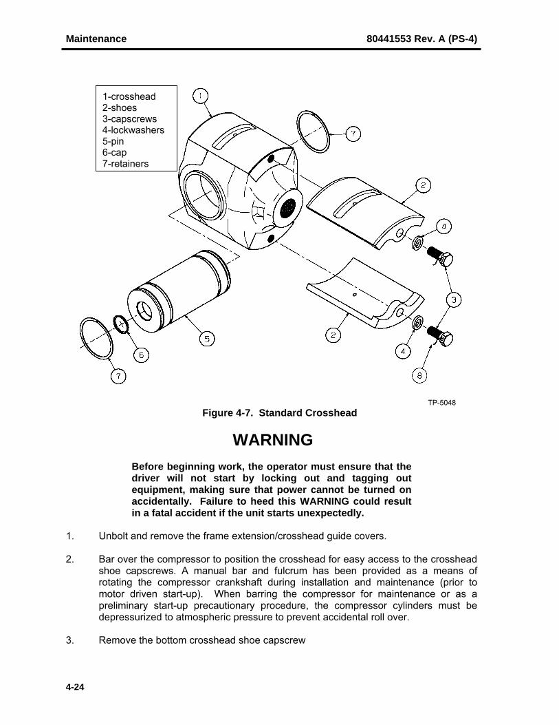
Maintenance 80441553 Rev. A (PS-4)
4-24
1-crosshead2-shoes3-capscrews4-lockwashers5-pin6-cap7-retainers
TP-5048Figure 4-7. Standard Crosshead
WARNINGBefore beginning work, the operator must ensure that thedriver will not start by locking out and tagging outequipment, making sure that power cannot be turned onaccidentally. Failure to heed this WARNING could resultin a fatal accident if the unit starts unexpectedly.
1. Unbolt and remove the frame extension/crosshead guide covers.
2. Bar over the compressor to position the crosshead for easy access to the crossheadshoe capscrews. A manual bar and fulcrum has been provided as a means ofrotating the compressor crankshaft during installation and maintenance (prior tomotor driven start-up). When barring the compressor for maintenance or as apreliminary start-up precautionary procedure, the compressor cylinders must bedepressurized to atmospheric pressure to prevent accidental roll over.
3. Remove the bottom crosshead shoe capscrew

80441553 Rev. A (PS-4) Maintenance
4-25
4. Using a pry bar as a lever under the connecting rod, raise the crosshead and hold itagainst the top guide then block under the connecting rod to support the crossheadin this position.
5. Slide out the worn shoe from under the crosshead and then slide a replacementshoe into place.
6. Reinstall the capscrew and lockwasher and tighten the capscrew securely to fastenthe shoe to the crosshead.
7. Make sure the shoe is well seated against the crosshead by probing along themating line of the shoe and crosshead with a 0.0015 inch (0.4 mm) feeler.
8. Remove the blocking and lower the crosshead to the bottom guide.
9. Replace the top shoe in a similar manner. Repeat Step 7 to ensure a good seatbetween the shoe and crosshead.
10. Measure the top shoe to guide clearance at all four corners and at the center using afeeler gauge. Refer to CHAPTER 5, GENERAL DATA AND CLEARANCES forassembly clearance.
11. Make sure the crosshead is resting squarely on the lower guide by checking forclearance under the bottom shoe; a 0.0015 inch (0.04 mm) feeler should not enterbetween the center of the bottom shoe and guide at either end of the shoe.
12. As a final check for proper shoe assembly, bar over the compressor while observingthe crosshead for proper travel.
13. Reinstall the frame extension/crosshead guide covers.
4-12. COMPRESSOR CYLINDERS
Good working habits are essential to the performance of satisfactory maintenancework on the compressor cylinder. When disassembling a cylinder, use every means to keepdirt and other foreign material away from the cylinder internals. Cover exposed openings tokeep dirt and debris out of the cylinder. Scratches, nicks or burrs must be removed frommachined surfaces. This can be done with fine sand paper, a fine hone or a mill file.Whenever honing, grinding or any other type of work is conducted that creates abrasive dustparticles, all cylinder surfaces and ports exposed must be thoroughly washed with soap andhot water (the only correct way to remove such particles, as solvent alone will not cleanthem out of the pores in the metal).
Mark or tag parts as they are disassembled so that they can be reinstalled in theiroriginal positions. Replace all gaskets that are torn, dried or cracked.
Instructions for servicing the compressor valves and regulation devices are coveredseparately in the job-specific Installation, Operation & Maintenance Manual.
The compressor cylinder can be opened and the various cylinder componentsserviced as described in the appropriate maintenance instructions. If the cylinder is to be

Maintenance 80441553 Rev. A (PS-4)
4-26
removed, it is necessary to disconnect all of the connecting air, oil, water and control piping,as applicable. The piston and rod assembly must also be removed from the cylinder.
Parts should be thoroughly cleaned in a site-approved safety solvent and inspectedfor wear and other visible defects before re-using them. Generally, unless otherwise stated,parts should be covered with a thin coating of clean lubricant before reassembly, exceptnon-lubricated (NL) cylinders.
WARNINGObserve all safety precautions contained in the safetysummary that precedes CHAPTER 1 of this instructionmanual and particularly those at the beginning of thischapter when working on the compressor cylinders. Add-itionally, before working on the cylinder, make sure thecompressor is blocked against accidental rollover andthat the power to the compressor is locked out andtagged with a sign "WORK IN PROGRESS - DO NOTSTART". Make absolutely sure to close intake anddischarge line valves and BLEED OFF AND VENT ANYRESIDUAL PRESSURE that may be trapped in thecompressor cylinders.
4-12.1. Removing The Outer Head
1. If applicable, shut off the cooling water.
2. Close inlet and discharge block valves and vent any air pressure from within thecylinder bore and passages to atmosphere. Closely observe all applicable safetyprecautions as stated in the beginning of this chapter.
3. Drain the coolant from the cylinder and outer head water jackets.
4. Place an eyebolt in the available bolt hole in the top of the outer head and attach thehead to an overhead hoist.
5. Loosen the outer head stud nuts and back them off about 1/4-inch (6 mm).
6. If jackscrew holes are provided, install screws tighten evenly to jack the outer headaway rom the cylinder. If no holes are provided, use a pry bar to pry the outer headloose.
7. With the outer head attached to an overhead hoist, the stud nuts can be removedand the head can be pulled from the cylinder. Make sure the head is supported atall times
8. Remove and discard the outer head gasket.
9. Clean the outer head-to-cylinder gasket surfaces and install a new gasket.

80441553 Rev. A (PS-4) Maintenance
4-27
10. To reinstall the outer head, attach the outer head to an overhead hoist, then placethe head over the cylinder studs. Install the stud nuts, then gradually and evenlytighten the nuts to draw the head against the cylinder. Torque the outer head studnuts as specified on the job-specific Cylinder Instructions located in the Installation,Operation & Maintenance Manual.
4-12.2. Removing the Piston and Piston Rod Assembly
The following instructions apply specifically to conventional, double-acting cylinders.
1. If not already done, remove the cylinder outer head as described previously.
2. Remove the side inspection covers from the crosshead guide and distance piece(s)that will provide access to the crosshead jam nut, pressure packing and oil scraperrings.
3. Remove the pressure packing and oil scraper rings. Always remove the packing andscraper rings before removing or installing the piston rod; never slide the threadedend of the piston rod through these rings.
4. Temporarily reassemble the packing case and scraper ring assemblies without therings.
5. Loosen the crosshead jam nut.
6. Unscrew the piston rod from the crosshead, using a strap wrench. Never use a pipewrench to turn the piston and rod assembly.
7. Pull the piston and rod assembly through the outer end of the cylinder. If used, slidethe oil slinger off the piston rod. Support the piston until the rod is clear of the boreto prevent damaging either the piston rod or bore surfaces.
8. Set the piston and rod in a safe place and protect the finished surfaces fromdamage. If the piston is to be separated from the piston rod, continue with thefollowing procedure.
4-12.3. Disassembling the Piston and Piston Rod
1. Clamp the piston rod in a suitable holding device, such as a set of V-blocks. Use asoft bearing material next to the rod surface and clamp the rod behind the rod collar,close to the piston.
2. Unscrew the piston nut (using the nut adapter if necessary). If available, a suitablesize impact wrench is ideal. If it is necessary to either sledge or use a cheater on thewrench, support the piston to prevent bending the piston rod, then slide the piston offthe rod.
4-12.4. Inspecting the Cylinder Bore
The cylinder bore is designed with sufficient thickness to allow reboring if excessivewear requires truing-up of the bore. When the cylinder is rebored, an oversize piston and/orrings will be necessary to match the new bore size.

Maintenance 80441553 Rev. A (PS-4)
4-28
The approach to repairing a cylinder bore depends on the extent of wear or damagesustained and the amount of material that can be safely removed. Final bore dimensionswill determine whether oversize rings and/or piston are required.
1. Wipe the cylinder bore clean with lint-free rags. It may be necessary to use anOSHA approved safety solvent to remove some deposits.
2. Shine a light into the cylinder bore and visually inspect for scratches, gouges andnicks.
3. Using an inside micrometer, measure and record the cylinder bore diameter at theframe end, center and outer end in both the horizontal and vertical planes.
4. By comparing frame end, center and outer end cylinder bore measurements, bothcylinder taper (end-to-end in the same plane) and out-of-roundness (same end, butdifferent plane) can be determined.
5. If the limits in Tables 4-2 or Table 4-3 are exceeded, it indicates that re-boring andre-ringing with oversize rings is required. In any event, it is recommended thatIngersoll-Rand be contacted for technical advice.
6. If required, remove the cylinder and hone the cylinder bore when surface scratches,burrs, or minor scuffing are present. However, the hone is not a corrective measurefor out-of-round, tapered, or barrel-shaped bores; the hone in these cases wouldfollow the shape of the bore and not be effective in correcting these conditions.
7. When reconditioning a cylinder, it is important to achieve a 20AA surface finish toensure adequate ring seat and longevity. After honing, clean cylinder using soapand hot water.
Table 4-2. Maximum Allowable Bore Wear Before ReconditioningMax Out-of-Round Before
Reconditioning (in.)Nominal BoreDiameter (in.)
Max Bore Size BeforeReconditioning (in.)
Teflon Rings Metallic Rings
23456789
10111213141516
17 & Over
2.0083.0114.0145.0176.0207.0238.0269.029
10.03311.03612.03913.04214.04515.04816.048
Nominal + 0.048
0.0030.00450.0060.00750.0090.01050.0120.01350.0150.01650.0180.01950.0210.02250.0240.024
0.0010.00150.002
0.00250.003
0.00350.004
0.00450.005
0.00550.006
0.00650.007
0.00750.0080.008

80441553 Rev. A (PS-4) Maintenance
4-29
Table 4-3. Maximum Allowable Taper Before ReconditioningStroke (in.) Taper (in.)
9 0.0045
4-12.5. Removing the Cylinder
1. Prepare the cylinder for removal by disconnecting all water piping, pneumatic tubing,etc. Use an overhead hoist or other suitable means to support the weight of thecylinder.
CAUTIONOn cylinders that have bolted on water jackets, ensurethat the lifting slings are not in contact with the jackets.The weight of the cylinder may be heavy enough tocollapse the jacket wall.
2. Remove the suction and discharge piping.
3. Loosen the cylinder-to-frame head/yoke stud nuts. Take up the weight of thecylinder with the lifting equipment.
4. Unbolt the outer end cylinder support, then remove all stud nuts and separate thecylinder from the frame head/yoke.
5. Remove and discard the frame head gasket.
6. Clean the frame head-to-cylinder gasket seating surfaces in preparation for re-assembly.
4-12.6. Installing and Aligning the Cylinder
1. Clean the frame head/yoke-to-cylinder gasket seating surfaces, then install a newgasket.
2. Attach the cylinder to the overhead hoist or other suitable means to support theweight of the cylinder.
CAUTIONOn cylinders that have bolted on water jackets, ensurethat the lifting slings are not in contact with the jackets.The weight of the cylinder may be heavy enough tocollapse the jacket wall.
3. Lift and place the cylinder studs through the clearance holes in the frame head/yokeand snug only one or two nuts at the top of the stud circle. The cylinder is centeredon the frame head/yoke by a shoulder which fits closely into the cylinder bore.

Maintenance 80441553 Rev. A (PS-4)
4-30
4. Clean the gasket surface for the inlet/discharge connection on top of the cylinder andplace a precision machinist's level (Starrett® 98) on this surface parallel to thecrankshaft. Rotate the cylinder until the inlet flange is level.
5. Tighten the cylinder-to-frame head stud nuts evenly and progressively. Refer to thejob-specific Cylinder Instructions for special cylinder bolting torque values located inthe job-specific Installation, Operation & Maintenance Manual.
6. Use a precision machinist’s level having a cross level and check that the bottom ofthe cylinder bore in the piston travel area runs parallel with the bottom of thecrosshead guide. Locate the cause of any misalignment and make adjustments.
7. The cylinder bore and crosshead guide need not be perfectly level, but must run inthe same plane. Do not use the cylinder inlet/discharge connection as an alternativeto the cylinder bore for checking parallelism. If the crosshead guide is level but thecylinder is not, the most likely cause is dirt or raised material in the joint where thecylinder fits the frame head/yoke.
8. Reattach the suction and discharge piping.
9. Reconnect all water piping, pneumatic tubing, etc. as required.
10. Reattach the outer end cylinder support and adjust accordingly.
4-12.7. Assembling the Piston and Piston Rod
1. Clamp the piston rod in a suitable holding device, such as a set of V-blocks. Use asoft bearing material next to the rod surface. Clamp the rod behind the rod collar,close to the piston.
2. Inspect the seating surfaces of the piston rod collar, piston faces and piston rod nutfor dirt, burrs and general condition. Clean up the part as required.
3. Place the piston on the rod and check the seating surfaces by "bluing" between thepiston rod shoulder and piston to assure that at least 75% of evenly distributedcontact is made on all seating surfaces. This is also true for multiple-piece pistons.Check that the contact area is uniform around the circumference and across thepiston rod to piston seating surface. If necessary, lap the faces with lappingcompound; remove all traces of lapping compound with soap and water.
4. Check the seating surface between piston nut and the piston for adequate contact asin Step 3. If the contact area is insufficient, check the squareness of the nut threads.If necessary, scrape or lap the faces with lapping compound; remove all traces oflapping compound using soap and water.
5. Assemble the piston onto the piston rod.
6. Apply an anti-seize lubricant, such as Dow Corning® G-n or FEL-PRO® C5-A, onboth the rod and nut threads. (These lubricants are available through mostcommercial suppliers.) Run the nut back and forth to ensure an even distribution oflubricant.
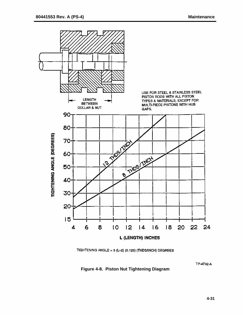
80441553 Rev. A (PS-4) Maintenance
4-31
Figure 4-8. Piston Nut Tightening Diagram

Maintenance 80441553 Rev. A (PS-4)
4-32
7. Apply lubricant to the nut face and piston face.
8. Screw the nut onto the piston rod. Hand-tighten the nut to seat the piston on the rodshoulder, then loosen the nut and re-tighten to a snug condition, approximately 100ft-lbs (135 N·m).
9. Referring to Figure 4-8, determine the number of degrees the piston nut must betightened.
10. Referring to Figure 4-9, scribe a line (A) across the face of the piston nut, then scribea line (B) across the end of the piston rod to mark the clockwise distance the nutmust tightened.
Figure 4-9. Scribing Tightening Angle
11. Tighten the piston nut so that the line on the nut corresponds to the line on the pistonrod. The nut face should be flush with the end of the piston rod, if not, the piston isnot assembled properly on the rod; reposition the piston and/or collars to obtain theproper arrangement.
CAUTIONIt is important that the piston nut is fully tightened twotimes, loosened, then retightened a third time. Thisensures good contact and seating between the rolledthreads on the rod and the machined threads on the nut.If these instructions are not followed, the nut may comeoff the piston rod causing severe damage to thecompressor.

80441553 Rev. A (PS-4) Maintenance
4-33
12. Loosen the piston nut and repeat Steps 8 through 11 two more times. Because ofthe new parts seating under the tightening pre-stress, it is anticipated that the nut willbe turned further at each re-tightening step. It is important to re-establish tighteningmarkings each time the nut is re-tightened.
13. Prick-punch four places between the piston nut and the rod threads to prevent thenut from loosening.
4-12.8. Installing the Piston and Rod Assembly
1. If required, install new piston and rider rings in their ring grooves and check them forproper side clearance and end gap
NOTE
Prior to installing the piston and rod, make sure the packingcase and scraper plate are installed. However, DO NOTinstall the packing, partition or scraper rings at this time.
2. Bar the compressor to position the crosshead at maximum frame end stroke.
3. Rig the piston and rod assembly to an overhead hoist, then lift and guide the pistonrod into the cylinder, using a band or other suitable means to compress the rings tostart them into the counterbore.
4. Continue to push the piston and rod into the cylinder. The end of the counterbore isbeveled to guide the rings the cylinder bore. Guide the piston rod through thepressure packing. Install the oil stop plate over the piston rod before the rod entersthe oil scrapper partition.
5. Screw the crosshead jam nut onto the piston rod as far as possible.
NOTE
It maybe helpful to utilize a small screw jack under the pistonrod to support the weight of the rod and facilitate installation.Mount a dial indicator to observe the rod movement. Jack therod up noting the distance moved as shown on the dialindicator, then lower the rod half the total indicated distance.This will take the weight of the rod off the crosshead, helpcenter the rod in the crosshead and prevent galling of themating threads. Use a wood block under the jack and heavycloth around the piston rod for protection.
6. Engage the lead end of the piston rod into the crosshead.
CAUTIONNEVER USE A PIPE WRENCH, OR ANY OTHER TOOLTHAT CAN SCRATCH OR OTHEERWISE DAMAGE THEPISTON ROD. Most pistons are drilled and tapped which

Maintenance 80441553 Rev. A (PS-4)
4-34
will allow a tee bar-type wrench to be attached to the outerface of the piston to screw the piston and rod assembly inor out of the crosshead. Where this is not possible, amechanical strap (Parmalee) wrench is recommended toturn the rod. Take every precaution to avoid scratching ornicking the piston rod surface. Even a slight nick in therod can ruin the pressure packing or oil scraper rings.
7. Thread the piston rod into the crosshead using a strap wrench until the pistoncontacts the frame head, then rotate the piston rod ½ turn out of the crosshead. Thisshould yield the required frame end clearance of 0.062 inches (+0.030/-.010) sincethe piston rod has 8 pitch threads at the crosshead end (one revolution = 0.125inch).
8. Lower and remove the screw jack if used.
9. Install a new outer head gasket, then lift the outer head and place it onto the cylinderstuds. Reinstall and tighten the stud nuts evenly and progressively to the torquespecifications given on the Cylinder Instructions located in the job-specificInstallation, Operation & Maintenance Manual.
SERVICE NOTE
Verify frame end and outer end piston clearances by removingvalve assemblies from both ends of the cylinder, then bar thecompressor over to position the piston at each end and insertfeeler gauges between the piston and each cylinder head.
10. Reset the piston end clearances as described in paragraph 4-13 if required.
11. Tighten the crosshead jam nut as shown in Figure 4-10.
a. Snug up (hand tight) the crosshead jam nut against the crosshead.
b. Scribe a line (A) across the nut and a line (B) 13º past line (A) across thecrosshead indicating the distance the nut must be advanced.
c. Tighten the crosshead jam nut until line (A) meets line (B).
12. It is recommended to mark the position of the piston and rod assembly to thecrosshead at this time so that the piston can be readily returned to its correct positionshould it be removed at some later time.
13. Install the packing and oil scraper rings as outlined in paragraph 4-15 and 4-16.However, do not install the rings if there will be a delay in operating the unit, as therings may corrode the piston rod.
14. Check the piston rod alignment (runout) as outlined in paragraph 4-14.

80441553 Rev. A (PS-4) Maintenance
4-35
Figure 4-10. Tightening Crosshead Jam Nut
4-12.9. Installing the Outer Head
1. Clean the outer head-to-cylinder gasket seating surfaces, then install a new gasket.
2. Attach the outer head to on overhead hoist, then lift and place the outer head ontothe cylinder studs.
3. Reinstall the outer head stud nuts and torque to the specification given on the job-specific Cylinder Instructions located in the Installation, Operation & MaintenanceManual. Tighten the stud nuts evenly and progressively following a crisscrosspattern.
4. Reconnect water piping as applicable.
4-13. PISTON END CLEARANCE
Specific end clearances for a particular cylinder are set for the factory-assembledairends. The piston end clearances need to be set and checked once the airends arereassembled. After being correctly set at the time of installation, should rarely requireadjustment. It should, however be checked occasionally.
If a knock or pound develops in a compressor cylinder and worn connecting rodbearings have been ruled out, the cause may be due to a loose piston or insufficient pistonto head clearance at one end of the piston stroke. If the cause is determined to be a loosepiston, retighten the piston nut as instructed in paragraph 4-12.7. If it is determined that theknock is due to the piston hitting one of the heads, it will be necessary to reset the clearanceat both ends of the stroke, as follows:

Maintenance 80441553 Rev. A (PS-4)
4-36
WARNINGLock out and tag power to compressor and relieve allpressures to atmosphere before entering the cylinder.Failure to heed this warning could result in severepersonal injury or death.
1. Remove a valve from each end of the cylinder.
2. Measure the piston end clearance as follows:
a. Hang a soft lead wire between the piston and the inside face of each cylinderhead, then bar the compressor over. When the frame (crank) end and outer(head) end stroke positions are reached, the wire will be flattened out equalto the amount of clearance.
OR ....
b. Using feeler gauges, measure the clearance between the face of the pistonand the outer head. Note this measurement and then bar over thecompressor to bring the piston to the opposite (frame) end of the cylinder.Again using feelers, measure the clearance between the face of the pistonand the frame head.
CAUTIONSet clearances carefully to avoid overtravel or expansioninto the counterbore at the ends of the cylinder. Impropersetting can result in a knock and/or ring breakage.
3. In general, the outer (head) end piston clearance should be approximately 2/3 or0.060” (1.52mm) more than the frame (crank) end piston clearance. This differencecompensates for thermal growth of the piston rod resulting from operatingtemperatures.
4. Make piston end clearance adjustments as follows:
a. Loosen the crosshead jam nut.
b. Screw the piston rod in or out of the crosshead the required amount.Standard piston rods have 8-pitch threads, therefore, one revolution of thepiston rod equals 0.125 inch (3 mm) change in end clearance.
c. Retighten the crosshead jam nut per paragraph 4-12.8.
4-14. PISTON ROD ALIGNMENT (RUNOUT)
Vertical and horizontal (side-to-side) movement of the compressor piston rod as itreciprocates during compressor operation is referred to as piston rod runout. The idealcondition is zero rod runout when the compressor is operating at normal pressures and

80441553 Rev. A (PS-4) Maintenance
4-37
temperatures. Perfect alignment is difficult to achieve. Therefore, a small amount of runoutis allowed (see Table 4-4).
Table 4-4. Piston Rod Runout Limits
Maximum Allowable VerticalRod Runout
Maximum Allowable HorizontalRod Runout
Non-AdjustableCrosshead
± 0.008 in. (0.20 mm) ± 0.003 in. (0.08 mm)
An important procedure during compressor installation and maintenance is checkingpiston rod runout and making necessary adjustments. A crosshead without shim-adjustableshoes (standard) must have the shoes replaced or other corrective action to maintainacceptable rod alignment.
Horizontal rod runout is affected by the alignment of the frame to the distancepiece(s) and the distance piece(s) to the cylinder. Excessive horizontal rod runout iscorrected by realignment and/or squaring of the distance piece(s) and cylinder flanges.
4-14.1. Factors That Influence Piston Rod Runout
• Excessive piping strain on the cylinder, or distorted cylinder supports pulling the cylinderout of alignment.
• Cylinder-to-distance piece joint burrs, or debris in the joint, causing the cylinder to bemisaligned.
• Excessive piston rider ring or cylinder bore wear. This can be checked by measuring theparts.
• If installed, one-piece rider bands can be worn on the bottom side. Rotating the pistonwill place a new rider band wear surface against the bore.
• A Worn crosshead or crosshead shoes. If crosshead or crosshead shoes are wornexcessively, close evaluation of the crosshead guide should be made.
• A worn piston rod; check rod diameters along the full length of the rod if this is suspect-ed. Also, check for bending; a worn or bent rod should be replaced.
• A crosshead jam nut not seating squarely against the crosshead nose; mis-machinedparts, burrs (usually on the crosshead nose) or debris can cause this situation.
4-14.2. Measuring Piston Rod Runout
1. For vertical piston rod runout, a dial indicator with a magnetic base is mounted on thepacking case flange so that the indicator reads on top of the piston rod at the 12:00position as shown in Figure 4-11. The dial indicator must be perpendicular to thepiston rod.

Maintenance 80441553 Rev. A (PS-4)
4-38
WARNINGBefore beginning work, the operator must ensure that thedriver will not start by locking out and tagging outequipment, making sure that power cannot be turned onaccidentally. Failure to heed this WARNING could resultin a fatal accident if the unit starts unexpectedly.
WARNINGCompressor cylinders must be depressurized toatmospheric pressure before barring. Compressorpistons will move to bottom-dead-center as an equilibriumcondition due to the difference in piston surface area (bypiston rod cross sectional area) exposed to the system airpressure. Failure to depressurize the compressorcylinders prior to barring may result in unexpectedrollover that can cause personal injury.
2. For horizontal piston rod runout, the dial indicator must read on the side of the pistonrod at 3:00 or 9:00 position, next to the pressure packing case, depending onaccessibility.
Figure 4-11. Dial Indicator Location and Piston Rod Length Measurement (L)
3. The crosshead jam nut must be properly tightened and the crosshead must be in fullcontact with the lower guide. Check this by making sure a 0.0015 inch (0.04 mm)feeler will NOT fit between the crosshead and lower guide at 6:00 position.
4. Bar over the compressor until the piston is at crank (frame) end stroke position.Depress the indicator button causing the dial indicator pointer to rotate one revolutionon the dial face. Set the dial face zero mark to align with the pointer. (This is knownas preloading and zeroing the indicator.)
5. Bar over the compressor through 180º, moving the piston from crank (frame) end tohead (outer) end. The largest reading seen during this 180° traverse to the head

80441553 Rev. A (PS-4) Maintenance
4-39
end, whether plus or minus, is the total runout. Record this measurement. In order tocheck the accuracy of this reading, continue barring over the compressor anadditional 180º (in the same direction of rotation) to crank end position. The dialindicator pointer should now be at zero; if not, the indicator has moved and theprocedure must be repeated.
6. If the runout exceeds the limits specified in Table 4-4, corrective action must betaken (see paragraph 4-14.1 for possible causes).
NOTE
If the dial indicator pointer "jumps" at the extreme ends of thestroke it can be an indication of a loose crosshead jam nut, anut face that is not square to the crosshead nose, or(particularly on large bore/small rod applications) simply thechange in rod motion and associated change in the frictionforce between the rider ring and cylinder bore at the end of thestroke.
A positive (+) rod runout measurement indicates that thecrosshead is high relative to the piston. A negative (-) rodrunout measurement indicates that the crosshead is lowrelative to the piston. This relationship is based on the pistonstroked from crank (frame) end to head (outer) end.
4-15. PRESSURE PACKING
The pressure packing should be removed, cleaned and inspected for wear on aregular basis. Experience and operating conditions will dictate the amount of time betweeninspection intervals.
When disassembling the packing case, do not use a chisel or sharp instrument toseparate the cups.
Packing rings must be free to float laterally in the cups and have the proper sideclearance. The cups must be free of nicks, burrs or scratches on the seating surfaces. Ifnecessary, lap the cups to renew the seating surfaces.
Some causes for packing wear or leakage are listed below:
● Excessive temperature due to failure of cooling system, excessive temperature ofcylinder, or sticking of the rings causing excessive friction.
● Moisture resulting from shutdowns causing corrosion, leading to abrasive conditionsand excessive wear/leakage.
● Dirt or debris from process causing excessive wear/leakage.
● Improper break-in of rings causing rapid wear/leakage.
● Improper assembly or excessive side clearance causing leakage.

Maintenance 80441553 Rev. A (PS-4)
4-40
● Piston rod damage causing abrasive conditions leading to excessive wear/leakage.
● Packing cup wear or damage caused by dirt, debris, or corrosion.
Removal:
It is not necessary to completely remove the packing case to service the packingrings, however, if limited space is available inside the distance piece and it will be difficult toobtain accurate clearance measurements, the packing case will have to be removed fromthe cylinder.
1. Remove the side covers from the distance piece that is adjacent to the cylinder.
2. Disconnect and plug the coolant and vent lines as applicable. If used, disconnect andremove the rod drop device.
3. Loosen and remove the packing flange stud nuts, then pry the packing case out ofthe frame head counterbore or "packing box" as far as possible.
4. Remove the tie bolt nuts and separate the flange from the cups, then slide the cupsoff the tie rods. Separate the cups along the piston rod.
Inspection:
1. To determine if replacement rings are required, measure the packing cup depth andthe ring set width, then subtract the ring set width from the cup depth. This will givethe ring side clearance as shown in Figure 4-12 and should not exceed the limitsspecified in Table 4-5. The maximum allowable packing ring radial wear is limited bythe ring segment end gaps. When the end gap is zero (except in case of backuprings and zero end gap pressure breakers), new rings should be installed. Whenbackup rings wear to a point 0.030 inch (0.76 mm) larger than the piston roddiameter, they should be replaced.
2. If excessive cup wear or damage is found, the cup will have to be replaced or re-machined to original specifications. The cups must be free of nicks, burrs orscratches on the sealing surfaces. If necessary, lap the cups to renew the sealingsurfaces.
Installation:
Ingersoll-Rand does not recommend using an entering sleeve to plunger a piston rodthrough a completely assembled packing case because certain ring materials and certainring types (tangent) can be damaged. If possible, rings should be assembled over the rod ona piece-by-piece basis. New packing rings must be free to float in the cups and have theproper side clearance as specified in Table 4-5.

80441553 Rev. A (PS-4) Maintenance
4-41
Table 4-5. Packing Ring Side Clearance
Original (New) SideClearance, in. (mm)
Maximum Side Clearance, in. (mm) @Cylinder Discharge Pressure, PSIG(MPa)Ring
MaterialCast IronCups Steel Cups
0 - 999(0 - 6.89)
1000-4999(6.9 - 34.5)
5000-9999(34.5 - 69)
Bronze orCast Iron
0.007 -0.009(0.18 - 0.23)
0.009 -0.011(0.23 - 0.28)
0.023(0.58)
0.018(0.46)
0.016(0.41)
PTFE(Teflon®)
0.017 -0.021(0.43 - 0.54)
0.020 -0.023 (0.51 -0.59)
0.053(1.3)
0.042(1.1)
0.037(0.94)
Figure 4-12. Side Clearance Measurement Diagram

Maintenance 80441553 Rev. A (PS-4)
4-42
Figure 4-13 Design Details of Radial and Step-Tangent Ring Set
1. Three common methods for matchmarking ring segments use numbers, letters ordimples. The ring segment matchmarks and radial-cut rings must always facemaximum pressure (toward cylinder). Radial and step-tangent rings must bedoweled together to prevent a direct leakage path through the radial gaps (seeFigure 4-13.
2. Assemble the packing rings in accordance with the parts list drawing and theseinstructions. Connect the garter spring around the piston rod, then place each ringsegment under the spring separately, making sure the segment identificationmarkings match and face the pressure. After the rings are assembled on the rod,slide them into their cup, then slide the cup over the tie rods.
Figure 4-14. Typical Packing Ring Arrangements
a. Double-acting ring sets can be installed in either direction, with the exceptionthat adjacent rings must be properly aligned by the dowel pin and matinghole.

80441553 Rev. A (PS-4) Maintenance
4-43
3. New packing rings should have side clearance in the cup as specified in Table 4-5.
4. Continue the procedure in Step 2 for all rings. If used, make sure that the coolantpassage O-rings are in place (the use of a silicone type lubricant will help keep theO-rings in position).
5. Install tie rod nuts and tighten securely.
6. Ensure the packing case gasket is in good condition, then slide the packing case intothe frame head counterbore or "packing box". If a new gasket is needed, the pistonrod will have to be removed (see instructions for removing the piston rod).
7. Reinstall the packing flange stud nuts and torque to specification; refer to the job-specific Cylinder Instructions. Make sure the flange is centered around the pistonrod; shift the packing case on the studs as required.
8. Reconnect the coolant and vent tubing as applicable. If used, install and reconnectthe rod drop device.
9. Reinstall the distance piece side covers and gaskets.
4-16. OIL SCRAPERS
The oil scrapers should be removed, cleaned and inspected for wear on a regularbasis. Experience and operating conditions will dictate the amount of time betweeninspections.
When oil scraper rings have worn to a point where the ends of ring segments buttthey should be replaced. The condition of the piston rod is also important factor for oilcontrol. Damaged or out-of-round piston rods will contribute to oil leakage regardless ofscraper ring condition. Springs should be washed clean of carbon and sludge, and then bechecked for proper tension and replaced as required.
Never slide the scraper rings over the threaded end of the piston rod which canscore the scraping edges of the rings.
A stuffer is bolted to a partition rib in the integral crosshead guide and distance pieceon the standard unit. The stuffer houses three oil wiper rings which prevent frame oil beingcarried out of the frame along the piston rod.
A typical stuffer and oil wiper ring arrangement is shown in Figure 4-15.
Removal:
1. Unbolt and remove the crosshead guide/distance piece guide side cover(s).
2. Unbolt and remove the capscrews that fasten the wiper ring gland or retainer plate tothe stuffer. Carefully slide the gland back over the piston rod so that the rod surfaceis not damaged.

Maintenance 80441553 Rev. A (PS-4)
4-44
3. Pull each oil wiper ring assembly back onto the rod and unfasten the garter spring topermit removal of the ring segments. Disassemble and remove all three oil wiperrings in this manner.
NOTE
Observe the arrangement and position of the wiper rings asthey are being removed. This will facilitate proper reinstallationof rings.
Inspection:
1. To determine if replacement rings are required, measure the side clearance asshown in Figure 4-12. If there is too much side clearance, the rings may cock anddamage the rod. If there is not enough side clearance, the rings may bind. Refer toTable 4-6 for original (new) and recommended maximum allowable scraper ring sideclearance.
2. If the scraper ring segments are touching (zero end gap), the rings need to bereplaced.
3. The condition of the piston rod is also an important factor for oil control. Damaged orout-of-round piston rods will cause oil leakage regardless of scraper ring condition.
Table 4-6. Oil Scraper Ring Side Clearance
RingMaterial
Original (New) Side Clearance Maximum Side Clearance
Bronze orCast Iron
0.005 - 0.0085 in. (0.18 - 0.22 mm) 0.021 in. (0.53 mm)
Installation:
1. The three scraper rings are bi-directional with scraping edges and drain slots on bothsides. Orient the rings so that the oil drain holes face the frame (see Figure 4-15).
2. Fasten the gland to the stuffer, centering it with respect to the piston rod.
NOTE
If the wiper ring stuffer (partition) has been removed and thenreinstalled, be certain that the oil drain opening is located atthe bottom.
3. Liberally oil the scraper rings before starting the compressor when new rings havebeen installed. The oil within the frame and crosshead guide will then keep the ringslubricated during normal operation and subsequent starts.
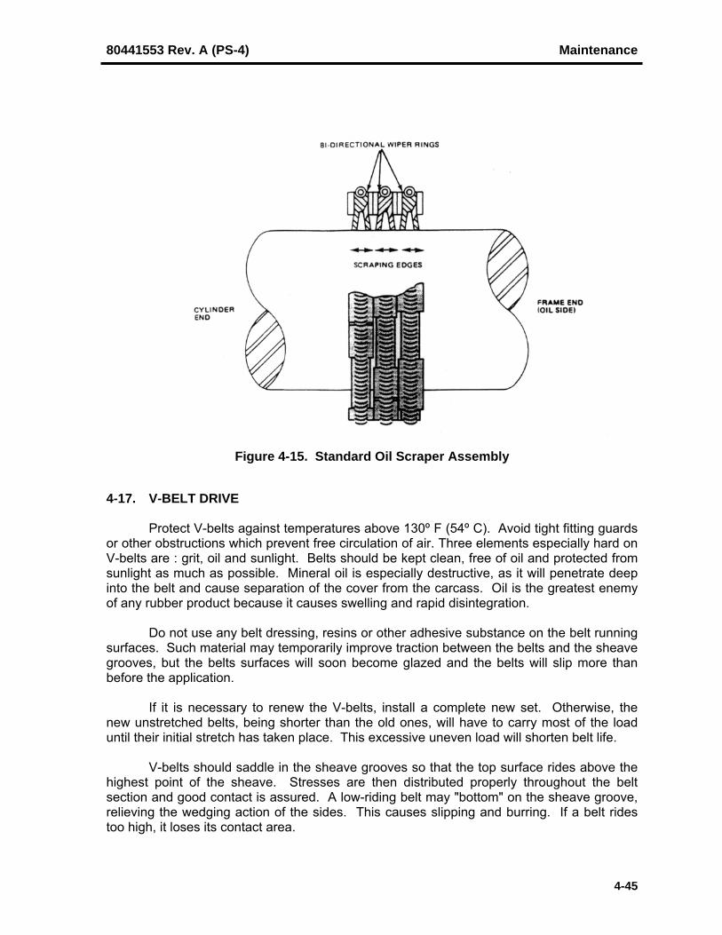
80441553 Rev. A (PS-4) Maintenance
4-45
Figure 4-15. Standard Oil Scraper Assembly
4-17. V-BELT DRIVE
Protect V-belts against temperatures above 130º F (54º C). Avoid tight fitting guardsor other obstructions which prevent free circulation of air. Three elements especially hard onV-belts are : grit, oil and sunlight. Belts should be kept clean, free of oil and protected fromsunlight as much as possible. Mineral oil is especially destructive, as it will penetrate deepinto the belt and cause separation of the cover from the carcass. Oil is the greatest enemyof any rubber product because it causes swelling and rapid disintegration.
Do not use any belt dressing, resins or other adhesive substance on the belt runningsurfaces. Such material may temporarily improve traction between the belts and the sheavegrooves, but the belts surfaces will soon become glazed and the belts will slip more thanbefore the application.
If it is necessary to renew the V-belts, install a complete new set. Otherwise, thenew unstretched belts, being shorter than the old ones, will have to carry most of the loaduntil their initial stretch has taken place. This excessive uneven load will shorten belt life.
V-belts should saddle in the sheave grooves so that the top surface rides above thehighest point of the sheave. Stresses are then distributed properly throughout the beltsection and good contact is assured. A low-riding belt may "bottom" on the sheave groove,relieving the wedging action of the sides. This causes slipping and burring. If a belt ridestoo high, it loses its contact area.

Maintenance 80441553 Rev. A (PS-4)
4-46
If the compressor is to be idle for any length of time, V-belts should be removed fromsheaves and stored in a cool, dry, dark place, preferably uncoiled, and hung over pegs on awall or rack. If left on equipment, V-belts acquire a permanent "set" which greatly increasespossibility of failure.
V-belts not in use should be stored in a cool, dark, dry place. If belts become watersoaked, or are piled on a damp floor, undue shrinkage may occur.

PET STAR 4CHAPTER 5
GENERAL DATA AND CLEARANCES
Paragraph Page
5-1. PET STAR 4 GENERAL AND OPERATING DATA ........................................ 5-2Table 5-1. General PET STAR 4 Specifications ..................................... 5-2Table 5-2. Component Dimensions ......................................................... 5-3Table 5-3. Component Materials.............................................................. 5-3Table 5-4. Operating Parameters............................................................. 5-4Table 5-5. Frame Lube Oil Specifications................................................ 5-4
5-2. ASSEMBLY FITS & CLEARANCES ................................................................ 5-5Table 5-6. Assembly Clearances (Inches) ............................................... 5-5
5-3. TIGHTENING REQUIREMENTS ...................................................................... 5-75-3.1. Preparation of Thread and Seating Surfaces ............................................. 5-75-3.2. Recommended Tightening Sequence ........................................................ 5-75-3.3. Closely Observe The Following .................................................................. 5-75-3.4. Checking Fastener Tightness ..................................................................... 5-85-3.4.1. When To Check Fastener Tightness .................................................... 5-85-3.4.2. How to Check Fastener Tightness ....................................................... 5-95-3.5. Fastener Pre-Stress ................................................................................... 5-95-3.6. Compressor Cylinder Bolting ...................................................................... 5-10
Table 5-7. Pre-Stress Levels ................................................................... 5-105-3.7. Torque Values ............................................................................................ 5-11
Table 5-8. Torque Table k=0.13 Anti-Seize ............................................. 5-11Table 5-9. Torque Table Common Mineral Oil Lubricant ......................... 5-12Table 5-10. Torque Wrench Values Anti-Seize.......................................... 5-13Table 5-11. Torque Wrench Values Common Mineral Oil Lubricant.......... 5-14

General Data And Clearances 80441553 Rev. A (PS - 4)
5-2
5-1. PET Star 4 GENERAL AND OPERATING DATA
The specifications in this Chapter apply to the standard 9-inch stroke PET Star 4compressor. Contact your Sales Representative or the nearest Sales Support Office whenthere is a question about any specification or recommendation.
Table 5-1. General PET Star 4 Specifications
Frame Size 4-Throw
MACCRL1, lbs. (kg) 21,600 (9,806)
MACGL2, lbs. (kg) 24,800 (11,259)
Stroke, in. (mm) 9 (228.6)
No. of Main Bearings 5
BHP3 (kW) at Rated Speed 786 (586)
Frictional BHP at Rated Speed 16
Maximum / Rated Speed 514
Minimum Operating Speed 350
Piston Speed at Rated Speed 771 ft/min
Type of Oil Pump Crankshaft Driven Gear
Oil Pump Output,GPM (L/min) @ max RPM 22 (83)
Frame Oil Capacity,gals. (L) 22.12 (83)
Lube Oil Filter 10 Micron Spin-On
Pre Lube Pump Auxilliary Motor Driven
NOTES:
1 MACCRL (Maximum Allowable Continuous Combined Rod Load).2 MACGL (Maximum Allowable Combined Gas Load) based on internal cylinder pressure.3 Horsepower ratings vary with the cylinder construction, operating conditions and location of the
most heavily loaded cylinders on the crankshaft. The maximum allowable horsepower for a given compressor under specific conditions may be higher or lower than the nominal horsepower.

80441553 Rev. A (PS - 4) General Data And Clearances
5-3
Table 5-2. Component Dimensions for PET Star 4
Crankshaft Pin 5.50 in. (139.7 mm) O.D.
Main Bearing 5.50 in. (139.7 mm) I.D. x 4.062 in. (103.2 mm) W
Crankpin Bearing 5.50 in. (139.7 mm) I.D. x 4.00 in. (101.6 mm) W
Connecting Rod Bushing 4.25 in. (107.95 mm) I.D. x 4.188 in. (106.38 mm) W
Crosshead 11.00 in. (279.4 mm) Diameter
Crosshead Pin 4.25 in. (107.95 mm) O.D. x 8.75 in. (222.25 mm) L
Crosshead Shoes 6.30 in. (160.02 mm) W x 8.75 in. (222.25 mm) L
Piston Rod 2.00 in. (50.8 mm) Diameter
Table 5-3. Component Materials for PET Star 4
Frame Gray Cast Iron
Frame Extensions / Distance Piece Gray Cast Iron
Main Bearings Steel Backed Bronze withBabbitt overlay
Crankshaft Forged Alloy Steel
Connecting Rod Forged Alloy Steel
Crankpin Bearings, Full-Floating Aluminum
Connecting Rod Bushing (Small End), Full-Floating High Leaded Tin Bronze
Crosshead Gray Cast Iron
Crosshead Shoes Cast Aluminum
Crosshead Pin Surface Hardened AlloySteel
Covers, Oil Pump & Drive End Carbon Steel Plate

General Data And Clearances 80441553 Rev. A (PS - 4)
5-4
Table 5-4. Operating Parameters for PET Star 4
Normal Oil Pressure (at Header) 50 psig (345 kPa)
Minimum Oil Pressure (at Header) 35 psig (241 kPa)
Shutdown Oil Pressure (at Header) 25 psig (173 kPa)
Minimum Start-up Oil Temperature 80º F (27º C)
Minimum Load Oil Temperature 90° F (32° C)
Normal Oil Operating Temperature 150º - 160º F (66º - 71º C)
Maximum Temperature Alarm Setting 180º F (82º C)
Maximum Temperature ShutdownSetting
190º F (88º C)
Cylinder Coolant Inlet Temperature Minimum 10º F (6º C) above gas inlet temp.
Cylinder Coolant Outlet Temperature 120º F (49º C)
Packing Coolant Flow Rate 2.0 GPM (7.6 LPM) per packing
Nominal Cylinder Coolant Pressure 35 PSIG (241 kPa)
Maximum Cylinder Coolant Pressure 75 PSIG (517 kPa)
Table 5-5. Frame Lube Oil Specifications1
Flash Point (Open Cup) 380º F (193º C) Minimum
Viscosity @ 100ºF (40ºC) 780 SSU (170 cSt) Maximum
Viscosity @ 210ºF (100ºC) 60 SSU (10 cSt) Minimum
Carbon Residue 0.45% Maximum
Strong Acid Number 0.00 Maximum
1 The oil must be a well-refined circulating type oil/petroleum product. It should not contain fats or fixed oilcompounding. Oil containing rust and oxidation inhibitors, and foam depressant is preferred. It must besubstantially non-corrosive to the common bearing metals. DO NOT use multi-grade oils or viscosityimprovers. The pour point of the oil should be at least 10°F (6°C) below ambient starting temperature.

80441553 Rev. A (PS - 4) General Data And Clearances
5-5
5-2. ASSEMBLY FITS AND CLEARANCES
Table 5-6. PET Star 4 Assembly Fits And ClearancesSYMBOL
(Figure 5-1)DESCRIPTION OF LOCATION MICROMETER
(Inches)FEELER(Inches)
AMain Bearing Clearance –Diametrical – Measured at Top ofCrankshaft and Main Bearing Shell
0.005” – 0.008” 0.004” – 0.007”
BMain Bearing Cap Interference –Force Fit of Main Bearing Cap intoFrame
(0.001” – 0.003”) ----------
CCrankshaft Thrust Clearance –Axial -Total Crankshaft MovementBetween Thrust Shoes
0.008” – 0.036” 0.007” – 0.035”
DCrankpin Bearing Clearance –Diametrical – Bearing Shell OD toConnecting Rod Crankpin Bore
0.001” – 0.003” <0.002”
ECrankpin Bearing Clearance –Diametrical – Bearing Shell ID toCrankshaft Crankpin
0.001” – 0.005” <0.004”
FCrankpin Bearing Clearance –Axial - Total Side MovementBetween Bearing and Crankweb
0.008” – 0.020” 0.007” – 0.019”
GConnecting Rod Clearance – Axial- Total Side Movement BetweenConnecting Rod and Crankweb
0.016” – 0.028” 0.015” – 0.027”
HCrosshead Pin Bushing Clearance– Diametrical – Bushing OD toConnecting Rod Wristpin Bore
0.001” – 0.0025” <0.0015”
JCrosshead Pin Bushing Clearance– Diametrical – Bushing ID toWristpin
0.002” – 0.003” <0.002”
KCrosshead Pin Bushing Clearance– Axial - Total Side MovementBetween Bushing and Crosshead
0.063” – 0.079” 0.062” – 0.078”
LConnecting Rod Clearance – Axial- Total Side Movement BetweenConnecting Rod and Crosshead
0.267” – 0.271” 0.266” – 0.270”
MCrosshead Wristpin Clearance –Diametrical – Wristpin OD toCrosshead Wristpin Bore
0.001” – 0.0025” <0.0015”
NCrosshead Shoe Clearance –Diametrical – Measured at Top ofCrosshead Shoe and Guide
0.010” – 0.018” 0.009” – 0.017”
PMain Bearing Tie Rod SpacerInterference – Force Fit of Tie RodSpacer into Frame
(0.004” – 0.006”) ----------

General Data And Clearances 80441553 Rev. A (PS - 4)
5-6
Figure 5-1. Location of Assembly Fits and Bearing Clearances

80441553 Rev. A (PS - 4) General Data And Clearances
5-7
5-3. TIGHTENING REQUIREMENTS
5-3.1. Preparation Of Thread And Seating Surfaces:
Preparation of thread and seating surfaces are equally important. In most torqueapplications, more than 80% of the applied torque is used to overcome friction and thebalance to actually stress the fastener. It is therefore imperative that threads are clean andfree of nicks and burrs; that seating surfaces on the nut or bolt head and mating surface besmooth, flat and parallel; and that the threads and contact surfaces be properly lubricated.
5-3.2. Recommended Tightening Sequence:
All fasteners used on multi-fastener joints require a tightening procedure that willallow the fasteners to be evenly and sequentially tightened, in gradual increments, to thespecified torque. This prevents distortion of mating surfaces and "cocking" of flangedconnections.
5-3.3. Closely Observe the Following:
1. All torque values are for clean, well-lubricated (see Item 3 below) threads free ofnicks and burrs. For stud (or bolt) and nut combinations, the nut should turn freely onthe stud threads. Capscrews should run in freely at least up to the final assembleddepth. (Some thread interference is normal on certain self-locking fasteners.)Lubricant should be evenly applied to both internal and external threads, and allseating surfaces.
2. Wrench torques can produce fastener pre-stress variations of ±35%, depending onthe degree of lubrication or non-lubrication, and also on the condition of seatingsurfaces. A properly calibrated torque wrench is essential in obtaining satisfactoryresults. Under no circumstances is an air impact wrench to be used for tightening ofany fastener.
3. Thread lubricants with a nut factor (k) of approximately 0.13 are recommended. Thisnut factor (k) is an average value of a commercially available copper based anti-seize, known as FEL-PRO® C5-A, and a commercially available molybdenumdisulfide (MoS2) based lubricant, known as Dow Corning® G-n. Using otherlubricants having a different nut factor (k) can result in increased or decreasedfastener pre-stress when the torque values in the Torque Table for Anti-Seize ThreadLubricant are applied.
4. Geared head wrenches (torque multipliers) will not produce the full mechanical ad-vantage from the reduction gears. There are mechanical and friction losses of about10% in the tool head. The tool manufacturer's instructions should be observed todetermine the exact reduction percentage for a particular torque multiplier. Therequired input torque must then be increased by that percentage.
5. The torque values listed in either Torque Table should be used only on thosefasteners for which a specific torque is not given.

General Data And Clearances 80441553 Rev. A (PS - 4)
5-8
5-3.4. Checking Fastener Tightness
WARNINGThe fasteners used in compressors must be correctlytightened to the design pre-stress to ensure safeoperation. After startup, fasteners that were properlytightened can loosen due to operating temperatures andpressures, gasket crush, fastener and joint relaxation.THEREFORE, IT IS IMPORTANT THAT FASTENERS BECHECKED FOR TIGHTNESS TO ENSURE FULLMECHANICAL INTEGRITY. Particular attention should begiven to all bolts, studs and nuts on the compressorcylinders and distance pieces and to the cylinder-to-framebolting.
WARNINGNever check fastener tightness or tighten fasteners withthe compressor in operation or pressurized. Potentialequipment damage and/or release of air could result,causing severe personal injury or death. Always checkand/or tighten fasteners when the compressor is shutdown and de-pressurized.
5-3.4.1. When to Check Fastener Tightness
Maintaining fastener tightness is critical to fastener reliability. Ingersoll-Randrecommends the following schedule for checking fastener tightness:
• Before start up for all joints that have gaskets and any joints not assembled at theIngersoll-Rand factory. (Consult the job-specific instruction manual parts list section tolocate joints containing gaskets.)
• One week after startup for joints with gaskets and all cylinder to frame bolting. Take noteof any fasteners that have loosened and pay close attention to these fasteners; thenincrease periodic checking of those fasteners.
• Anytime a joint containing a gasket is opened. Replace the gasket and tighten fastenersas prescribed and check again one week after start up.
• Periodically, based on experience, but annually is considered a typical interval.
• Anytime there is an incident, slugging event (liquid ingestion) or excessive vibration,which has caused a compressor overload to occur.

80441553 Rev. A (PS - 4) General Data And Clearances
5-9
5-3.4.2. How to Check Fastener Tightness
To check the tightness of a torqued fastener, first mark the position of the bolt head or nutand then loosen it; clean and re-lubricate. The fastener should then be re-torqued to therequired value. Observe to see whether the bolt head or nut has advanced past itsreference position. If it has, then the fastener has loosened, or was not originally torquedcorrectly. Inspect the fastener for fatigue or stress cracks; replace as required. ContactIngersoll-Rand for technical advice.
5-3.5. Fastener Pre-Stress
Fastener pre-stress (initial tightening) is calculated to prevent separation of the con-nected members when they are subjected to operating forces and, in cases of cyclicloading, to protect the fastener from the fatigue effects of the alternating tensile andcompressive stresses. Torque is the most widely used method of applying fastener pre-stress. A properly calibrated torque wrench is essential in obtaining satisfactory results. Anaccurate torque cannot be applied to fasteners using a commercial impact wrench. Underno circumstances is an impact wrench to be used for final tightening of any fastener.
NOTE
Refer to the job-specific Instruction Book for specific boltingtorque values before applying these general guidelines.
In general, unless otherwise specified, the pre-stress level for a particular boltingapplication can be determined as follows.
• For connections with metal-to-metal contact, use 30,000 PSI (207 MPa) stress level.
• For connections with non-metallic gaskets, use 20,000 PSI (138 MPa) stress level.
• For foundation bolts of the J type or bent bar use 25 000 PSI (172 MPa) stress level.Note this type of anchor bolt should NEVER be used for locations that have to withstandthe dynamic loads from the compressor frame or cylinders.
• For foundation bolts which use plate type anchors (recommended for compressor frameand cylinder anchor bolt locations) tighten to 30,000 PSI (207 MPa) stress level.
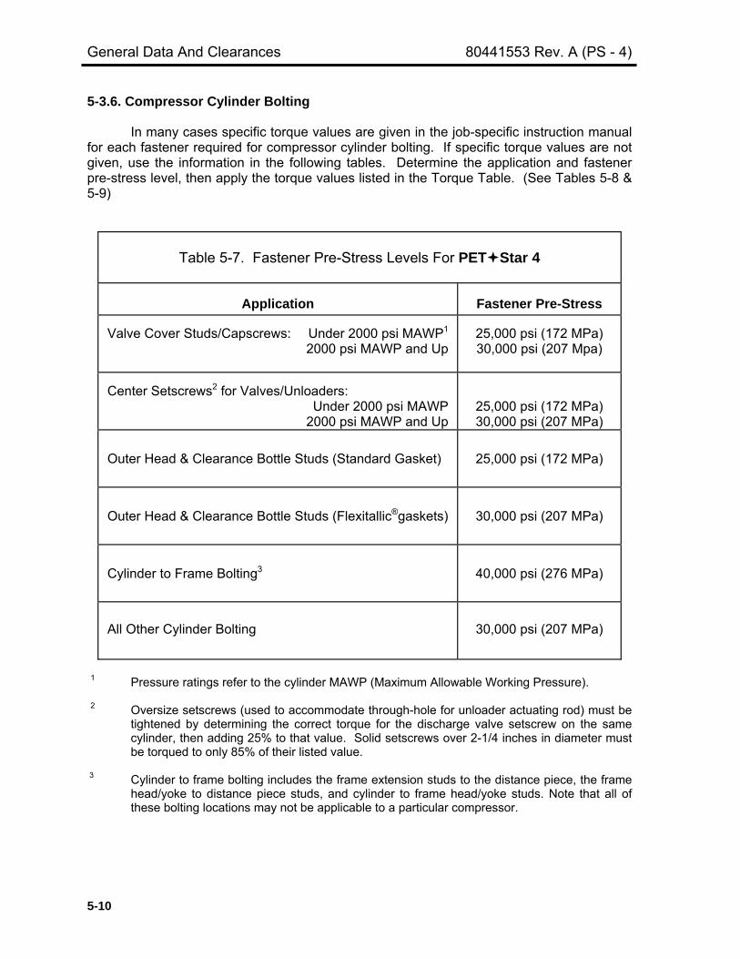
General Data And Clearances 80441553 Rev. A (PS - 4)
5-10
5-3.6. Compressor Cylinder Bolting
In many cases specific torque values are given in the job-specific instruction manualfor each fastener required for compressor cylinder bolting. If specific torque values are notgiven, use the information in the following tables. Determine the application and fastenerpre-stress level, then apply the torque values listed in the Torque Table. (See Tables 5-8 &5-9)
Table 5-7. Fastener Pre-Stress Levels For PET Star 4
Application Fastener Pre-Stress
Valve Cover Studs/Capscrews: Under 2000 psi MAWP1
2000 psi MAWP and Up25,000 psi (172 MPa)30,000 psi (207 Mpa)
Center Setscrews2 for Valves/Unloaders:Under 2000 psi MAWP
2000 psi MAWP and Up25,000 psi (172 MPa)30,000 psi (207 MPa)
Outer Head & Clearance Bottle Studs (Standard Gasket) 25,000 psi (172 MPa)
Outer Head & Clearance Bottle Studs (Flexitallic®gaskets) 30,000 psi (207 MPa)
Cylinder to Frame Bolting3 40,000 psi (276 MPa)
All Other Cylinder Bolting 30,000 psi (207 MPa)
1 Pressure ratings refer to the cylinder MAWP (Maximum Allowable Working Pressure).
2 Oversize setscrews (used to accommodate through-hole for unloader actuating rod) must betightened by determining the correct torque for the discharge valve setscrew on the samecylinder, then adding 25% to that value. Solid setscrews over 2-1/4 inches in diameter mustbe torqued to only 85% of their listed value.
3 Cylinder to frame bolting includes the frame extension studs to the distance piece, the framehead/yoke to distance piece studs, and cylinder to frame head/yoke studs. Note that all ofthese bolting locations may not be applicable to a particular compressor.

80441553 Rev. A (PS - 4) General Data And Clearances
5-11
5-3.7. Torque Values
Table 5-8. TORQUE VALUES BASED ON ANTI-SEIZE THREAD LUBRICANTTorque Table For Nut Factor (k = 0.13)
20,000 psi(138 MPa)Pre-Stress
25,000 psi(172 MPa)Pre-Stress
30,000 psi(207 MPa)Pre-Stress
40,000 psi(276 MPa)Pre-Stress
NominalThreadSize (in)
ft-lbs N•m ft-lbs N•m ft-lbs N•m ft-lbs N•m
0.2500.3120.3750.4380.5000.5620.6250.7500.8751.0001.1251.2501.3751.5001.7502.0002.1252.2502.5002.7503.0003.2503.5003.7504.0004.5005.0005.5006.000
1.73.56.3101522315488131193271367485789
120114511734240632324229541267978400
1023814679202482666534794
2.34.88.51421304174
119178261367498657
107016281967235132624383573473389216113891388119902274523615347174
2.24.47.91319283868
109164241338459606987
15011814216830084041528667658496105001279718348253093333143493
2.96.0111726375292
148222327459623822
1338203524592939407854787167917211520142371735124877343154519158968
2.65.39.41523334682
131197289406551727
1184180121772601360948496344811810196126011535722018303713999752191
3.57.21321314562
111178267392551747986
16062442295135274893657486011100713823170842082129852411785422970761
3.47.11320314461
109175262385542735970
15792401290234684812646584581082413594168012047629357404955333069588
4.7101727426083
147237356522734996
1315214132563935470265258765114681467518431227792776139803549047230594349
Observe the following when using this Torque Table [k = 0.13]:
● All information and instructions given under TIGHTENING REQUIREMENTS must bethoroughly reviewed before applying specified wrench torques.
● Torque values are based on thread lubricants with a nut factor (k) of approximately 0.13.This nut factor (k) is an average value of a commercially available copper based anti-seize,named FEL-PRO® C5-A, and a commercially available molybdenum disulfide (MoS2) basedlubricant, known as Dow Corning® G-n.
● The wrench torques are applicable to both National Fine and National Coarse thread series.Any difference in the torque values because of thread series is within the normal variation oftorque wrench accuracy.
● When tightening fasteners incorporating a self-locking feature, a certain amount of theapplied torque is lost because of the additional friction of the locking feature. Use a torquewrench to measure the "run-down" torque and then add it to the listed value.

General Data And Clearances 80441553 Rev. A (PS - 4)
5-12
Table 5-9. TORQUE VALUES BASED ON A COMMON MINERAL OIL LUBRICANT
20,000 PSI 25,000 PSI 30,000 PSI 40,000 PSI(138 Mpa) (172 Mpa) (207 Mpa) (276 Mpa)Pre-Stress Pre-Stress Pre-Stress Pre-Stress
NOMINALBOLT SIZE Torque Torque Torque Torque
(inches)Ft-lbs. N•m Ft-lbs. N•m Ft-lbs. N•m Ft-lbs. N•m
1/45/163/8
7/161/2
9/165/83/47/81
1-1/81-1/41-3/81-1/21-3/4
22-1/42-1/22-3/4
3
359
1522314476
120175260360480620950
14702130295039505150
47
1220304260
103163237355490650840
129019902890400053606980
37
121828395595
150220330450600770
119018302670365049006400
4101624305375
129203300450610815
1045161524803620495066408680
48
1422334766
114180265390530710920
142022003200440059007700
6111930456490
155244360530720965
125019252980434059708000
10440
5111929446388
152240350520710950
123018902930427058507850
10250
71526396085
119206325475705965
129016702565397059707930
1064013900
Observe the following when using this Torque Table:
● All information and instructions given under TIGHTENING REQUIREMENTS must bethoroughly reviewed before applying specified wrench torques.
● Torque values are based on common mineral oil lubricants.
● The wrench torques are applicable to both National Fine and National Coarse thread series.Any difference in the torque values because of thread series is within the normal variation oftorque wrench accuracy.
● When tightening fasteners incorporating a self-locking feature, a certain amount of theapplied torque is lost because of the additional friction of the locking feature. Use a torquewrench to measure the "run-down" torque and then add it to the listed value.

80441553 Rev. A (PS - 4) General Data And Clearances
5-13
Table 5-10. Torque Wrench Values Based on Anti-Seize Thread Lubricant
BOLT ORSTUD
LOCATION
THREADSIZE
(in-thds/in)
DISTANCEACROSS
FLATS (in)
REQUIREDPRESTRESS
(psi)TORQUE(Ft-lbs)
TORQUE(N-m)
Frame Top Covers 0.375-16UNC 9/16 20,000 6.3 8.5Drive End Cover 0.500-13UNC 3/4 20,000 15 21Oil Seal Retainer 0.250-20UNC 7/16 25,000 2.2 2.9Main Oil HeaderCover
0.500-13UNC 3/4 20,000 15 21
Main BearingCaps
0.750-10UNC 1 1/4 40,000 109 147
Thrust BearingShoes
0.250-20UNC 5/32 HEX 25,000 2.2 2.9
Oil Pump EndCover
0.500-13UNC 3/4 – 7/8 20,000 15 21
Oil PumpAssembly
0.375-16UNC 9/16 30,000 9.4 13
Crankshaft OilSlinger
0.312-18UNC 1/4 HEX 30,000 5.3 7.2
Distance PieceStuds
0.875-9UNC 1 5/16 40,000 175 237
Distance PieceCovers
0.500-13UNC 3/4 20,000 15 21
Distance PieceSupport
0.750-10UNC 1 1/8 30,000 82 111
Connecting RodBolts
1.375-12UNF 2 1/16 26,550 520 705
Crosshead ShoeBolts
0.750-10UNC 1 1/8 30,000 82 111
Oil Suction Header 0.500-13UNC 3/4 20,000 15 21
Observe the following when using this Torque Table [k = 0.13]:
● All information and instructions given under TIGHTENING REQUIREMENTS must bethoroughly reviewed before applying specified wrench torques.
● Torque values are based on thread lubricants with a nut factor (k) of approximately 0.13.This nut factor (k) is an average value of a commercially available copper based anti-seize,named FEL-PRO® C5-A, and a commercially available molybdenum disulfide (MoS2) basedlubricant, known as Dow Corning® G-n.
● The wrench torques are applicable to both National Fine and National Coarse thread series.Any difference in the torque values because of thread series is within the normal variation oftorque wrench accuracy.
● When tightening fasteners incorporating a self-locking feature, a certain amount of theapplied torque is lost because of the additional friction of the locking feature. Use a torquewrench to measure the "run-down" torque and then add it to the listed value.

General Data And Clearances 80441553 Rev. A (PS - 4)
5-14
Table 5-11. Torque Wrench Values Based on a Common Mineral Oil Lubricant
BOLT ORSTUD
LOCATION
THREADSIZE
(in-thds/in)
DISTANCEACROSS
FLATS (in)
REQUIREDPRESTRESS
(psi)TORQUE(Ft-lbs)
TORQUE(N-m)
Frame TopCovers
0.375-16UNC 9/16 20,000 9 12
Drive End Cover 0.500-13UNC 3/4 20,000 22 30Oil Seal Retainer 0.250-20UNC 7/16 25,000 3 4Main Oil HeaderCover
0.500-13UNC 3/4 20,000 22 30
Main BearingCaps
0.750-10UNC 1 1/4 40,000 152 206
Thrust BearingShoes
0.250-20UNC 5/32 HEX 25,000 3 4
Oil Pump EndCover
0.500-13UNC 3/4 – 7/8 20,000 22 30
Oil PumpAssembly
0.375-16UNC 9/16 30,000 14 19
Crankshaft OilSlinger
0.312-18UNC 1/4 HEX 30,000 8 11
Distance PieceStuds
0.875-9UNC 1 5/16 40,000 240 325
Distance PieceCovers
0.500-13UNC 3/4 20,000 22 30
Distance PieceSupport
0.750-10UNC 1 1/8 30,000 114 155
Connecting RodBolts
1.375-12UNF 2 1/16 26,550 720 975
Crosshead ShoeBolts
0.750-10UNC 1 1/8 30,000 114 155
Oil SuctionHeader
0.500-13UNC 3/4 20,000 22 30
Observe the following when using this Torque Table:
● All information and instructions given under TIGHTENING REQUIREMENTS must bethoroughly reviewed before applying specified wrench torques.
● Torque values are based on common mineral oil lubricants.
● The wrench torques are applicable to both National Fine and National Coarse thread series.Any difference in the torque values because of thread series is within the normal variation oftorque wrench accuracy.
● When tightening fasteners incorporating a self-locking feature, a certain amount of theapplied torque is lost because of the additional friction of the locking feature. Use a torquewrench to measure the "run-down" torque and then add it to the listed value.
Related Documents