Quality Level 2 (QL2) LIDAR Utilization at NCDOT NC Microstation Local Users Group (December 16, 2015) Keith Johnston, PE, PLS

Welcome message from author
This document is posted to help you gain knowledge. Please leave a comment to let me know what you think about it! Share it to your friends and learn new things together.
Transcript

Quality Level 2 (QL2) LIDAR Utilization at NCDOT
NC Microstation Local Users Group
(December 16, 2015)
Keith Johnston, PE, PLS
Transportation
Quality Level 2 (QL2) LIDAR Utilization at NCDOTTopics
• North Carolina QL2 LiDAR Program Organization
• North Carolina QL2 LiDAR Technical Details
• 2015 Collection Status
• How to get the Data
• Who is using the data at NCDOT
• NCDOT Photogrammetry QL2 LiDAR Assessment and Utilization
2

Transportation
North Carolina QL2 LiDAR Program Organization
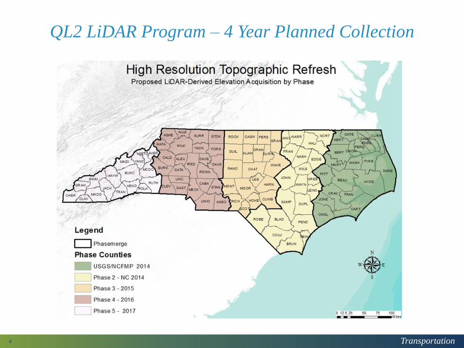
• Planned 4 year program to collect QL2 LiDAR statewide
• QL2 LiDAR collection & post processing by private sector
• State team members are:• NC Emergency Management (Risk Management)
• NC Department of Transportation (Photogrammetry Unit)
• NC Emergency Management (Geodetic Survey)
• NCDOT support for the project includes:• Up to $6.8 million in funding
• Technical advisory staffing
• Quality review staffing
• NCDOT funding is scheduled as follows:• 2014 - $3.8 million
• 2015 - $1.0 million
• 2016 - $1.0 million
• 2017 - $1.0 million
• NCDOT funding is subject to NCEM obtaining funding from other partners
• NCEM has not obtained funding for 2016 collection to date
3
Transportation
QL2 LiDAR Program – 4 Year Planned Collection
4

Transportation
North Carolina QL2 LiDAR Program Tech Details
• Nominal 2 pulse per square meter spacing
• Fundamental Vertical Accuracy (FVA) is 0.59 feet• Points in open terrain
• Expressed at a 95% confidence level
• Automated classification of points as follows: • Ground
• Water
• Vegetation (3 strata – low, medium, high)
• Buildings
• Roads (NCDOT system)
• Bridges (NCDOT system)
• Deliverables include:• Height modernization
• QL2 LiDAR collection
• QL2 LiDAR in LAS format
• Digital Elevation Models (DEM) at 10 foot, 20 foot, and 50 foot post spacing
• Terrain Datasets (by county)
• QC Accuracy Assessments (by county)
5

Transportation
2014 Calibration Range QL2 LiDAR Data – Point Density
6

Transportation
2014 Phase 2 QL2 LiDAR NVA Accuracy Assessment
7
Transportation
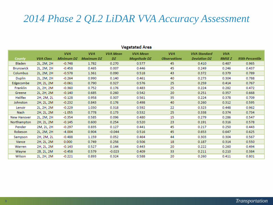
2014 Phase 2 QL2 LiDAR VVA Accuracy Assessment
8
Transportation
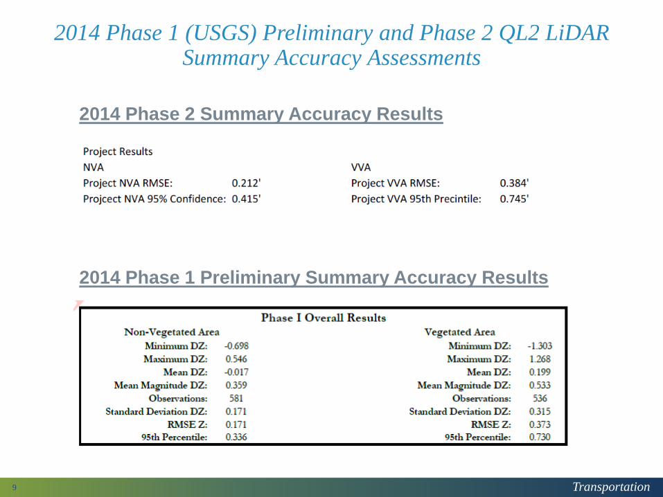
2014 Phase 1 (USGS) Preliminary and Phase 2 QL2 LiDAR Summary Accuracy Assessments
9
2014 Phase 2 Summary Accuracy Results
2014 Phase 1 Preliminary Summary Accuracy Results

Transportation
2015 QL2 Collection
10
2 Teams• AMEC
• Quantum Spatial
• AECOM• Woolpert
• QC for final 3 counties underway
• Data should be available +/- 1st
Quarter 2016
Transportation
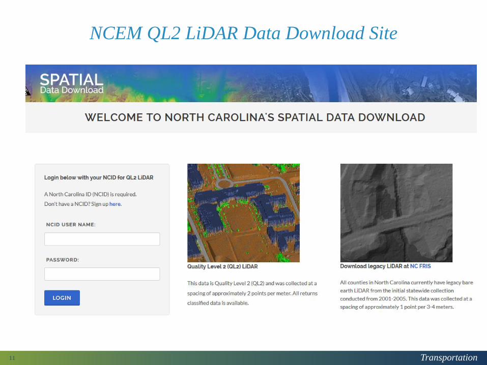
NCEM QL2 LiDAR Data Download Site
11

Transportation
NCEM QL2 LiDAR Data Download Site
12
Transportation
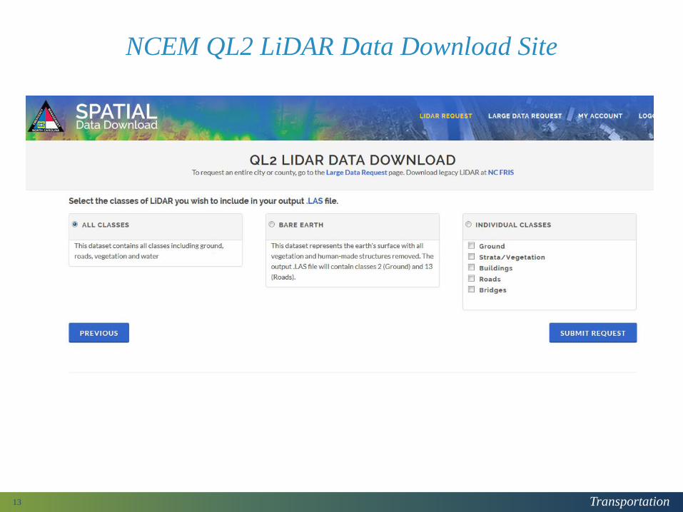
NCEM QL2 LiDAR Data Download Site
13

Transportation
Who is using QL2 LiDAR at NCDOT
14
• Hydraulics Unit - (Jerry Snead - [email protected])
• Standard practice is to use best available elevation data to supplement final surveys project TIN
• Location & Surveys Unit – (Donnie Stallings - [email protected])
• DTM mass points for final surveys
• Initial obscure area elevation data for final surveys – updated upon request from designer
• PDEA (Planning, Development, & Environmental Analysis) Group
• Wetland modeling (Morgan Weatherford - [email protected])
• Archaeologic investigations (Damon Jones - [email protected])
• Photogrammetry Unit (Keith Johnston – [email protected])
• 3-D flight planning in mountainous terrain
• Elevation model for orthorectification of near vertical imagery
• DTM mass points for preliminary design mapping
• DTM mass points for final surveys

Transportation
Accessing QL2 LiDAR for NCDOT Staff
• Next Generation LiDAR Working Group
• Meet every other month
• Group members include Asset Management, Construction,,Hydraulics, IT-CADD, IT- GIS, IT-Infrastructure, Location & Surveys, PDEA, Roadside Environmental, and Roadway Design
• Photogrammetry Unit stores bare earth data and 10 foot DEM data on NCDOT servers
• All staff with NCDOT logins have read access
• “Extract DEM” program to access gridded data
• “Get Decimated” program to access bare earth and decimated data from terrain datasets
• Photogrammetry Unit Contacts
• Charles Lee ([email protected])
• Marc Swartz ([email protected])
15

Transportation
NCDOT Photogrammetry QL2 LiDAR Evaluation
• Tracked the NC Geodetic Survey accuracy assessments
• Performed semi-automated and visual QC for 15% of tiles
• Semi-automated QC (all QL2 LiDAR LAS tiles)
• Compare to NCDOT LRS to verify all paved roads classified
• Compare to NCDOT bridges to verify all bridges classified
• Identify elevation anomalies (spike or pit) in ground classified points
• Identify elevation anomalies (spike or pit) in road classified points
• Visual QC
• Tile come up in correct location
• Clusters of buildings missed (800 sq ft min building size)
• Bodies of water > 2 acres not classified as water
• Streams > 100 ft wide not classified as water
• Assess the QL2 LiDAR to determine how best to utilize for Photogrammetry’s processes and products
16
Transportation
NCDOT Photogrammetry QL2 LiDAR Assessment for its Processes and Products
• Concerned about the size of the data
• Concerned about how it represents ground features
• Concerned about accuracy
• Accuracy as compared to higher order survey (NCGS)
• Dependent on LAS tile or DEM spacing
• Dependent on terrain type
• Accuracy of the QL2 LiDAR to itself
• Due to the point density
• One way to visualize is to think of smooth surface repeatability
17

Transportation
NCDOT Photogrammetry QL2 LiDAR Assessment for its Processes and Products
Data for our assessment (on-going process)
• 2014 QL2 LiDAR calibration range LAS data
• 2013 Wake County “QL2 like” LAS data (NCDOT TIP I-5506)
• 2014 Phase 2 QL2 LiDAR Whiteville pilot area (NCDOT TIP R-5020)
• Any NCDOT TIP preliminary mapping and final survey project covered by the QL2 LiDAR
• U-4407
• Higher order surveys from NCDOT Location & Surveys Unit
18

Transportation
Size of Data - 2014 QL2 LiDAR calibration range LAS data
19

Transportation
NCDOT Photogrammetry QL2 LiDAR Assessment for its Processes and Products
Size of the Data
• NCDOT uses MicroStation and GeoPak for surveys, mapping, and design
• Dense point clouds over typical project study areas aren’t presently handled efficiently in MicroStation
• Due to both file size and processing
• Need to reduce the data size which will reduce processing time
• 2014 QL2 LiDAR calibration range LAS data
• Located in south Raleigh (covers NC Farmer’s Market, part of I-40/I-440)
• 20,000 ft x 20,000 ft area
• Sixteen (16) 5,000 ft x 5,000 ft tiles
20

Transportation
NC QL2 LiDAR Validation Range
Phase 2 used 3 firms for
LiDAR Collection
Completed February 2014
Non-Vegetated Accuracy
at 95% Confidence Level
0.17 feet
0.22 feet
0.26 feet
NCDOT Photogrammetry
also conducted a controlled
low altitude flight using its
Digital Mapping Camera

Terrain Dataset - Bare Earth

Terrain Dataset 0.5 ft Decimation

Terrain Dataset 1.0 ft Decimation

Terrain Dataset 2.0 ft Decimation
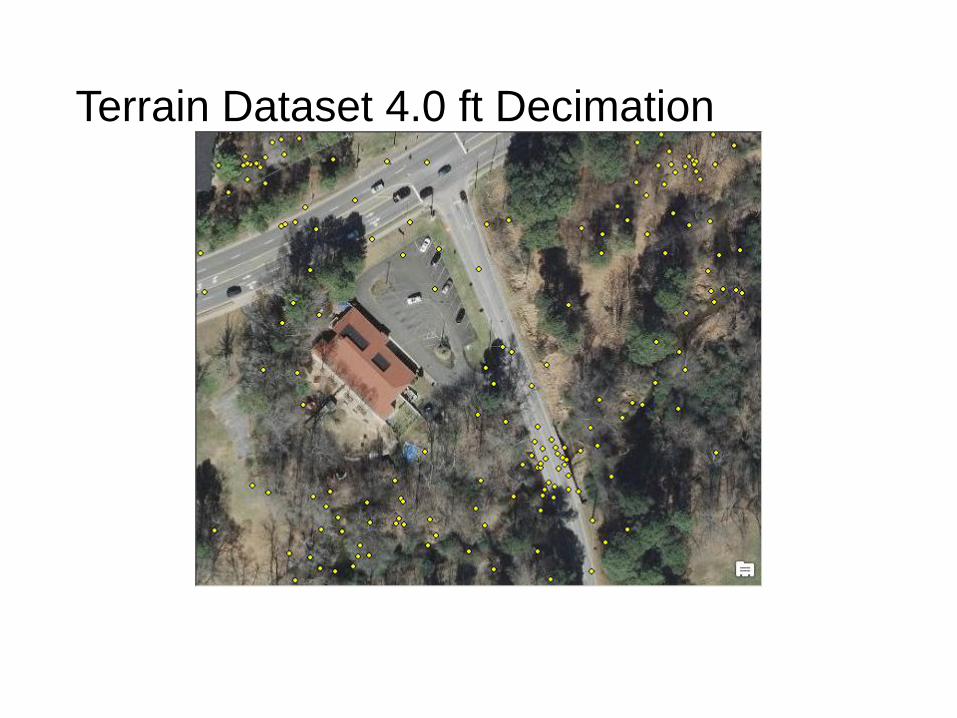
Terrain Dataset 4.0 ft Decimation

Transportation
Terrain Dataset Size – NC QL2 Validation Range
20000 ft by 20000 ft 9182 acre
6096 meter by 6096 meter 37161216 square meters
NCFMP Lidar Validation Range Site Metrics
Decimnation
Level (ft)Point Count % of level 0
Points
per acre
Points per
square meter
0 40509827 4412 1.090
0.1 27734118 68.5% 3020 0.746
0.2 16694979 41.2% 1818 0.449
0.3 9688649 23.9% 1055 0.261
0.4 5730770 14.1% 624 0.154
0.5 3694936 9.1% 402 0.099
0.6 2615110 6.5% 285 0.070
0.7 1973132 4.9% 215 0.053
0.8 1550754 3.8% 169 0.042
0.9 1260097 3.1% 137 0.034
1.0 1056108 2.6% 115 0.028
2.0 524677 1.3% 57 0.014
4.0 290905 0.7% 32 0.008

Transportation
Terrain Dataset Accuracy (QL2 VR Special Flight)
Decimation (ft) 0.0 0.5 1.0 2.0 4.0
Count 16 16 16 16 16
Min (ft) -0.21 -0.46 -0.28 -0.99 -1.37
Max (ft) 0.20 0.32 0.62 1.03 2.13
Mean (ft) 0.00 -0.08 0.18 0.05 0.46
Std Dev (ft) 0.12 0.18 0.28 0.47 0.83
RMSE (ft) 0.12 0.20 0.34 0.47 0.95
FVA (ft) 0.24 0.39 0.66 0.93 1.86
Ground Surveyed Panel Control (GPS by L&S)
Decimation (ft) 0.0 0.5 1.0 2.0 4.0
Count 82 82 82 82 82
Min (ft) -0.41 -0.47 -0.84 -1.46 -3.62
Max (ft) 1.06 0.96 1.04 1.55 2.13
Mean (ft) 0.01 0.00 0.02 0.05 0.05
Std Dev (ft) 0.25 0.26 0.35 0.61 1.20
RMSE (ft) 0.25 0.26 0.35 0.61 1.20
FVA (ft) 0.49 0.51 0.69 1.19 2.35
Densified Control (Photogrammetric)
Transportation
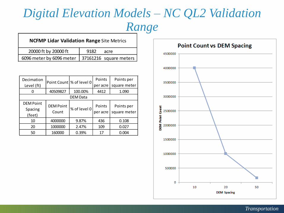
Digital Elevation Models – NC QL2 Validation Range
20000 ft by 20000 ft 9182 acre
6096 meter by 6096 meter 37161216 square meters
NCFMP Lidar Validation Range Site Metrics
Decimation
Level (ft)Point Count % of level 0
Points
per acre
Points per
square meter
0 40509827 100.00% 4412 1.090
DEM Point
Spacing
(feet)
DEM Point
Count% of level 0
Points
per acre
Points per
square meter
10 4000000 9.87% 436 0.108
20 1000000 2.47% 109 0.027
50 160000 0.39% 17 0.004
DEM Data

Transportation
DEM Accuracy (QL2 VR Special Flight)
DEM Spacing (FT) 10.0 20.0 50.0
Count 16 16 16
Min (ft) -0.21 -0.17 -1.62
Max (ft) 0.46 1.05 4.27
Mean (ft) 0.11 0.16 0.48
Std Dev (ft) 0.15 0.30 1.26
RMSE (ft) 0.19 0.34 1.35
FVA (ft)PP 0.38 0.67 2.64
Ground Surveyed Panel Control (GPS by L&S)
DEM Spacing (FT) 10.0 20.0 50.0
Count 82 82 82
Min (ft) -0.61 -1.53 -3.34
Max (ft) 0.94 1.82 4.27
Mean (ft) 0.03 0.04 0.11
Std Dev (ft) 0.29 0.45 1.01
RMSE (ft) 0.30 0.46 1.02
FVA (ft) 0.58 0.89 2.00
Densified Control (Photogrammetric)
Transportation
Size of Data & Accuracy- 2014 Phase 2 QL2 LiDAR Whiteville pilot area (NCDOT TIP R-5020)
31

R5020_m7319_m_120310.sid
1 inch = 104 feet

Compiled Breaklines and Masspoints
1 inch = 104 feet

The Decimated QL2 Lidar Points (half foot)
1 inch = 104 feet

Decimated QL2 Distance from Compiled Surface
Green Points: Within +/- 0.3 feet of Compiled surface TIN
Blue Points: Between +/- 0.3 to +/- 0.6 feet away from Compiled surface TIN
Red Points: Over +/- 0.6 feet away from Compiled surface TIN 1 inch = 104 feet

Points removed by proximity to breaklines and buildings (>10ft)
1 inch = 104 feet

Transportation
Ground Feature Representation & its Accuracy to Itself – NCDOT TIP U-4407 Final Surveys DTM
37

Transportation
NCDOT Project Experience with QL2 LiDARTIP U-4407, US 70 BUS/Berkley Blvd, Wayne County
38
• Photogrammetric break lines from 0.17 foot GSD imagery
• QL2 LiDAR DEM points at 10 foot spacing

Transportation
NCDOT Project Experience with QL2 LiDARTIP U-4407, US 70 BUS/Berkley Blvd, Wayne County
39
• Bare earth QL2 LiDAR ~ 2 points per square meter density

Transportation
NCDOT Project Experience with QL2 LiDARTIP U-4407, US 70 BUS/Berkley Blvd, Wayne County
40
• Planimetric features compiled from 0.17 foot GSD stereo imagery

Transportation
NCDOT Project Experience with QL2 LiDARTIP U-4407, US 70 BUS/Berkley Blvd, Wayne County
41
• 200 foot wide cross sections at 100 foot intervals
Transportation
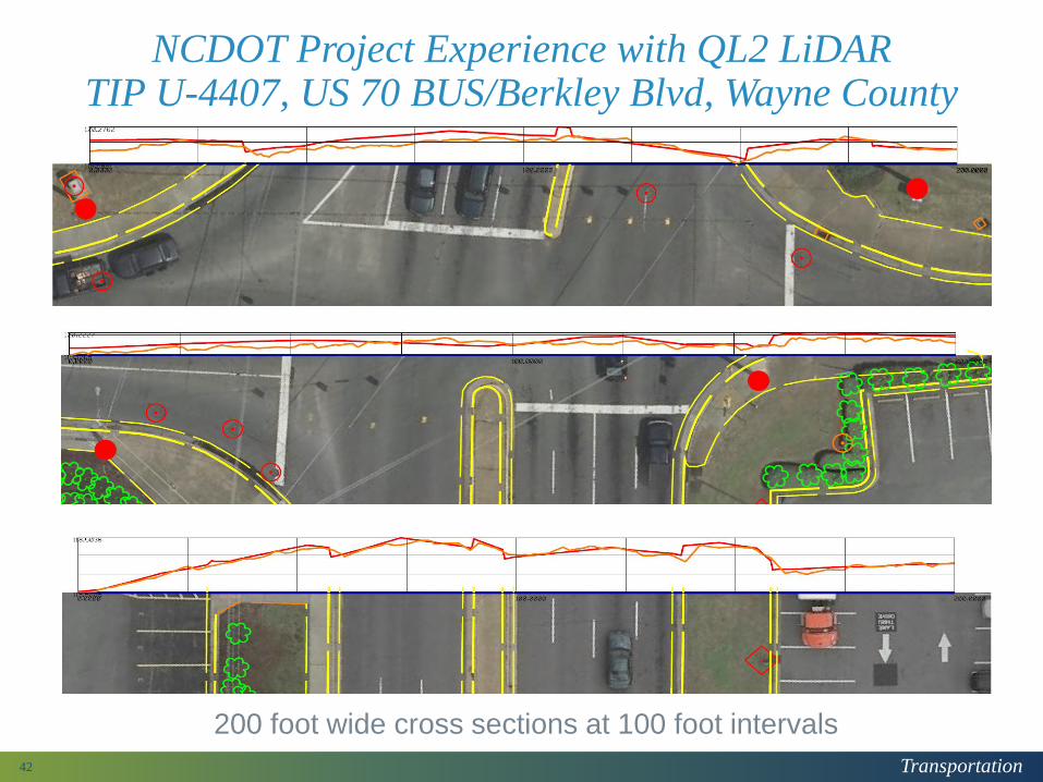
NCDOT Project Experience with QL2 LiDARTIP U-4407, US 70 BUS/Berkley Blvd, Wayne County
42
200 foot wide cross sections at 100 foot intervals

Transportation
NCDOT Photogrammetry QL2 LiDAR Assessment for its Processes and Products
How NCDOT Photogrammetry Used the QL2 LiDAR
• Initially used the 0.5 foot decimated data in our mapping and final surveys supplemented with photogrammetric break lines
• Flight Planning
• Use gridded DEM (spacing dependent on project size)
• Elevation model for orthorectification of near vertical imagery
• Use 20 foot gridded DEM
• DTM mass points for preliminary design mapping
• Use 20 foot gridded DEM supplemented with photogrammetric break lines
• DTM mass points for final surveys
• Use 10 foot gridded DEM supplemented with photogrammetric break lines
• Full implementation into standard operating procedures
• Using it on ~ 100 projects
43

Transportation
NCDOT Photogrammetry QL2 LiDAR Assessment for its Processes and Products
Questions
Keith Johnston, PE, PLS
State Photogrammetric Engineer
44
Related Documents