Pyrogen (Australia) Pty. Ltd. P.O. Box 694 Hurstville 1481 Suite 2, 9 Gloucester Road Hurstville NSW 2220 Australia Tel: 61 2 9586 3200 Fax: 61 2 9586 3211 E-mail: [email protected] Website: www.pyrogen.com Industrial Manual: DOM – 00/07 Issued; July, 2000 Revision No.: 1.8 INDUSTRIAL FIXED AEROSOL FIRE SUPPRESSION SYSTEM DESIGN, OPERATION & MAINTENANCE MANUAL July 2000 This manual is issued by Pyrogen (Australia) Pty. Ltd. and is for use by trained and authorised personnel only. Unauthorised copying of this manual and its contents and use by unauthorised personnel is strictly forbidden and may lead to legal action against those who do so. This document is accurate at time of issue and Pyrogen reserves the right to make changes to its content from time to time.

Pyrogen - Industrial Fixed Aerosol Fire Suppression System
Dec 27, 2015
FIRE
Welcome message from author
This document is posted to help you gain knowledge. Please leave a comment to let me know what you think about it! Share it to your friends and learn new things together.
Transcript
Pyrogen (Australia) Pty. Ltd. P.O. Box 694 Hurstville 1481 Suite 2, 9 Gloucester Road Hurstville NSW 2220 AustraliaTel: 61 2 9586 3200 Fax: 61 2 9586 3211 E-mail: [email protected] Website: www.pyrogen.com
Industrial Manual: DOM – 00/07 Issued; July, 2000Revision No.: 1.8
INDUSTRIAL FIXED AEROSOL FIRE SUPPRESSION SYSTEM
DESIGN, OPERATION& MAINTENANCE
MANUAL
July 2000
This manual is issued by Pyrogen (Australia) Pty. Ltd. and is for use by trained and authorisedpersonnel only. Unauthorised copying of this manual and its contents and use by unauthorised
personnel is strictly forbidden and may lead to legal action against those who do so.This document is accurate at time of issue and Pyrogen reserves the right to make changes to its
content from time to time.

Pyrogen (Australia) Pty. Ltd.
Industrial Manual: DOM – 00/07 (i) Issued: July, 2000Revision No.: 1.8
Document Revision Control Schedule
Doc. RevNo
RevisionDate
Comment Approved
1.0 01/09/98 For final internal comment PB/JMB1.1 28/10/98 For Issue to LPCB (1) MW/JMB1.2 07/12/98 UK Office Address Change & Aesthetics JMB1.3 11/12/98 Health & Safety Areas Highlighted JMB1.4 20/01/99 Design Calcs. Modified as per Dr.J.Berezovsky JMB1.5 16/04/99 Appx B – Gen. Selection Chart – Removed. JMB1.6 23/06/99 Modified as per request Dr.J.Berezovsky JMB1.7 20/1/00 Added information on thermal initiating device JMB
1.8 24/7/00 Revised drawings & other minor changes JB/AMPAC
Pyrogen (Australia) Pty. Ltd.
Industrial Manual: DOM – 00/07 (ii) Issued: July, 2000Revision No.: 1.8
FOREWORD
This Manual is intended for use with Pyrogen Industrial Fire Suppression Systems. Thesystems are designed as fixed systems for unoccupied and normally unoccupied areas.
Pyrogen systems for total flooding applications shall comply with the requirements of thefollowing Standards:
- AS/NZS 4487:1997 Australia/New Zealand Standard Pyrogen Fire Extinguishing Systems; and
- AS/NZS 1851.16:1997 Australia/New Zealand Standard Maintenance of Fire Protection Equipment Part 16: Pyrogen Fire Extinguishing Aerosol Systems
For the protection of a specified risk area a specific advice and approval may berequired from an appropriate Approval Authority.
Those who design, operate, own and maintain these systems should read the entireManual. Specific sections would be of particular interest depending on one’sresponsibility. If there should be any questions regarding this manual, please contactour representatives from a Pyrogen office below or contact the nearest PyrogenAuthorised Representative.
Where required persons who install and commission Pyrogen systems must beapproved by the Appropriate Authorities. System Design Approval Certificates must becompleted and sent to a Pyrogen office for endorsement prior to supply and installationof a Pyrogen Fire Suppression System.
Approved companies may also be required to supply details to the Approval Authorityprior to each installation and provide a Commissioning Certificate upon completion ofthe installation in the specified risk areas.
The Pyrogen Fire Suppression System requires minimal maintenance, mainlysupervision of electrical circuitry, however the system should be inspected at regularintervals to provide maximum assurance that your fire suppression system will operateeffectively and safely. Inspection and maintenance should be conducted in accordancewith the inspection and maintenance schedule included in this Manual.
This Manual is limited for use with Pyrogen Industrial Fire Suppression Systems andwithin the requirements and limitations detailed within this Manual.
Pyrogen (Australia) Pty. Ltd.
Industrial Manual: DOM – 00/07 (iii) Issued: July, 2000Revision No.: 1.8
Queries can be directed to Pyrogen personnel in the following Pyrogen offices:
Australian Office:
PYROGEN (AUSTRALIA) PTY. LTD.Suite 2, Ground Floor,9 Gloucester Rd.,Hurstville NSW 2220,Australia.
Tel.: +(61-2) 9586-3200Fax: +(61-2) 9586-3211Email: [email protected]
Pyrogen Headquarters:
PYROGEN CORPORATION SDN. BHD.No. 40-1, Jalan PJS 5/2,Taman Desaria,46000 Petaling Jaya,Selangor Darul Ehsan,Malaysia.
Tel.: +(60-3) 787-64688Fax: +(60-3) 787-54688Email: [email protected]
UK Office:
PYROGEN LTD.Gilnow Mill Business Centre,Spa Road, Bolton,BL1 4LFUK
Tel.: +(44) 1204 373300Fax: +(44) 1204 373355Email: [email protected]
Pyrogen (Australia) Pty. Ltd.
Industrial Manual: DOM – 00/07 (iv) Issued: July, 2000Revision No.: 1.8
TABLE OF CONTENTS
FOREWORD......................................................................................................II
SECTION 1. GENERAL .............................................................................. 1-01.1 Terminology .................................................................................................................................. 11.2 PyroGen Product Standards/Testing ............................................................................................ 41.3 What is PyroGen?......................................................................................................................... 41.4 PyroGen Chemical Identity ........................................................................................................... 51.5 PyroGen Extinguishing Action ...................................................................................................... 81.6 PyroGen and Competitive Products............................................................................................ 101.7 PyroGen Applications and Limitations ........................................................................................ 111.8 PyroGen Safety Data .................................................................................................................. 131.9 PyroGen Environmental Characteristics ..................................................................................... 151.10 PyroGen Technical Characteristics........................................................................................... 16
SECTION 2. SYSTEM DESIGN FOR TOTAL FLOODING APPLICATIONS2-02.1 General ......................................................................................................................................... 12.2 Design Methodology ..................................................................................................................... 12.3 Design Factor................................................................................................................................ 22.4 Design Quantity ............................................................................................................................ 22.5 Number of MAG generators .......................................................................................................... 22.6 PyroGen Range ............................................................................................................................ 42.7 Minimum Holding Time ................................................................................................................. 72.8 Enclosure Requirements............................................................................................................... 72.9 Design Quantity Calculations - Special Conditions....................................................................... 82.10 Design Limitations .................................................................................................................... 162.11 PyroGen Discharge................................................................................................................... 16
SECTION 3. SYSTEM DESIGN FOR LOCAL APPLICATIONS.................. 3-03.1 PyroGen Packaged Systems. ....................................................................................................... 1
SECTION 4. SYSTEM OPERATION........................................................... 4-04.1 Electrical automatic operation....................................................................................................... 14.2 Electrical manual operation .......................................................................................................... 14.3 Thermal automatic operation ........................................................................................................ 14.4 System isolate switch.................................................................................................................... 14.5 Operating devices ......................................................................................................................... 24.6 Detection, alarm and control systems, indicating equipment, warning devices ............................ 24.7 Post-fire procedure ....................................................................................................................... 2
SECTION 5. SYSTEM COMPONENTS ...................................................... 5-0
SECTION 6. SYSTEM INSTALLATION ...................................................... 6-06.1 Prior to installation ........................................................................................................................ 16.2 Incorporation of Thermal Initiating Device………………………………..……………………………. 26.3 Spacing and Location ................................................................................................................... 36.4 Mounting Methods ........................................................................................................................ 46.5 Electric Wiring............................................................................................................................... 76.6 Connection of Thermal Initiating Device ....................................................................................... 8
Pyrogen (Australia) Pty. Ltd.
Industrial Manual: DOM – 00/07 (v) Issued: July, 2000Revision No.: 1.8
SECTION 7. SYSTEM MARKINGS............................................................. 7-07.1 PyroGen Installation and Expiry Date Label ................................................................................. 17.2 PyroGen Warning & Instruction Signs ......................................................................................... 1
SECTION 8. SYSTEM COMMISSIONING.................................................. 8-0
SECTION 9. SYSTEM MAINTENANCE...................................................... 9-0
SECTION 10. SAFETY MEASURES ........................................................ 10-010.1 Personnel safety ......................................................................................................................... 110.2 Potential hazards ........................................................................................................................ 210.3 Re-entry ...................................................................................................................................... 210.4 Clean- up .................................................................................................................................... 3
10.5 Handling Fire Conducting Cord………………………………………………………………………..310.6 Hot Work..................................................................................................................................... 310.7 Storage and Transportation ........................................................................................................ 3
APPENDIX A -- APPROVAL DOCUMENTATION......................................A-0FORM 1 -- SYSTEM DESIGN APPROVAL CERTIFICATE ................................................................ 1FORM 2 -- COMMISSIONING AND ACCEPTANCE TESTING .......................................................... 4FORM 3 -- NOTICE OF COMPLETION .............................................................................................. 8FORM 4 -- MAINTENANCE CHECK LIST .......................................................................................... 9FORM 5 -- ANNUAL MAINTENANCE CERTIFICATE ...................................................................... 10
Industrial Manual: DOM – 00/07 1-0 Issued: July, 2000Revision No.: 1.8
FIXED AEROSOL FIRE SUPPRESSION SYSTEM
SECTION 1
GENERAL
Industrial Manual: DOM – 00/07 1-1 Issued: July, 2000Revision No.: 1.8
SECTION 1. GENERAL
1.1 Terminology
The following definitions apply to this document:
Actuating mechanism: automatic or manual activation leading to the physical dischargeof the extinguishant.
Aerosol: an extinguishant consisting of finely divided solid particles and gaseous matter,these being combustion products of solid aerosol-forming composition.
Aerosol generator: same as Pyrogen generator
Aggressive environment: where environmental variables such as temperature and/orvibration undergo cycling at or close to the extreme limits of the Pyrogen generator.Corrosive atmosphere may also be a factor.
Appropriate authority: a Minister of the Crown, a government department, or other publicauthority having power to issue regulations, order or other instructions having the forceof law in respect of any subject covered by an Industry Standard or, in the case wherenone of these apply, the owner or the owner's agent.
Approved and approval: approved by, or the approval of, the appropriate authority.
Automatic: performing a function without the necessity of human intervention.
Automatic/Manual Switch: a device that can be operated before a person enters aspace protected by Pyrogen fire suppression system to prevent automatic release of fireextinguishing aerosol. Normal detection sequence is unaffected.
Class A fires: fire involving solid materials, usually of organic nature. Can be furthercategorised into surface burning fires and deep-seated fires. Deep-seated firessmoulder and may combust slowly beneath the surface of the hazard.
Class B fires: fires involving liquids or liquefiable solids.
Class C fires: fires involving gases.
Class E fires: electrically energised fuels.
Class F fires: fats and cooking oils.
Combustion reaction: a reaction resulting from the activation of a solid aerosol-formingcomposition, which produces fire extinguishing aerosol.

Industrial Manual: DOM – 00/07 1-2 Issued: July, 2000Revision No.: 1.8
Control device: a device to control the sequence of events leading to the release of theextinguishant.
Cooling element: a heat absorbing medium.
Design concentration (g/m3): the mass of Pyrogen aerosol per m3 of enclosure volumerequired to extinguish a specific type of fire, including a safety factor.
Design Factor (g/m3): the mass of Pyrogen solid aerosol-forming composition per m3 ofenclosure volume required to achieve the design concentration.
Design quantity: the mass of Pyrogen solid aerosol-forming composition necessary toextinguish a fire in a particular risk, including a safety factor.
Extinguishant: aerosol produced from Pyrogen generator.
Generator: same as Pyrogen generator.
Holding time: the period during which the extinguishant is required to maintain aminimum effective concentration.
Hot Work: grinding, welding, thermal or oxygen cutting or heating and other relatedheat-producing or spark-producing operations.
Inerting: the prevention of ignition of a flammable or explosive atmosphere byestablishing a suitable concentration of extinguishant.
Location drawing: a plan of the risk clearly indicating the as-installed location of allPyrogen generators, controls and maintenance isolate switch.
Manual: requiring human intervention to accomplish a function.
Monitoring: the supervision of the operating integrity of an electrical control feature of asystem.
Normally occupied area: an area where, under normal circumstances, humans arepresent.
Normally unoccupied area: an area that is not occupied by humans under normalcircumstances but may be entered occasionally for brief periods.
Operating device: any component involved between actuation and release.
Primary release: release of extinguishant initiated by detection system or manualoperation under normal conditions.

Industrial Manual: DOM – 00/07 1-3 Issued: July, 2000Revision No.: 1.8
Pyrogen generator: a device capable of generating the Pyrogen aerosol extinguishantwhen activated either electrically or thermally. Consists of an electrical and/or thermalactivation device, solid aerosol-forming element and cooling element enclosed within acorrosion-resistant casing incorporating an end-plate nozzle.
Release: the action leading to the physical discharge or emission of the extinguishantinto the enclosure.
Shall: indicates that a statement is mandatory.
Should: indicates a recommendation.
Smouldering: slow combustion of material without visible light and generally evidencedby smoke and an increase in temperature.
Solid aerosol-forming element: a mixture of combustible component, potassium saltbased oxidant and technical admixtures producing fire-extinguishing aerosol uponactivation.
System isolate switch: see Automatic/Manual switch.
Thermal activation device: a linear fuse, which automatically activates at a ratedtemperature or when exposed to a naked flame and arranged to activate the solidaerosol forming element.
Total flooding system: a fixed fire suppression system, which distributes theextinguishing medium throughout the protected enclosure.
Industrial Manual: DOM – 00/07 1-4 Issued: July, 2000Revision No.: 1.8
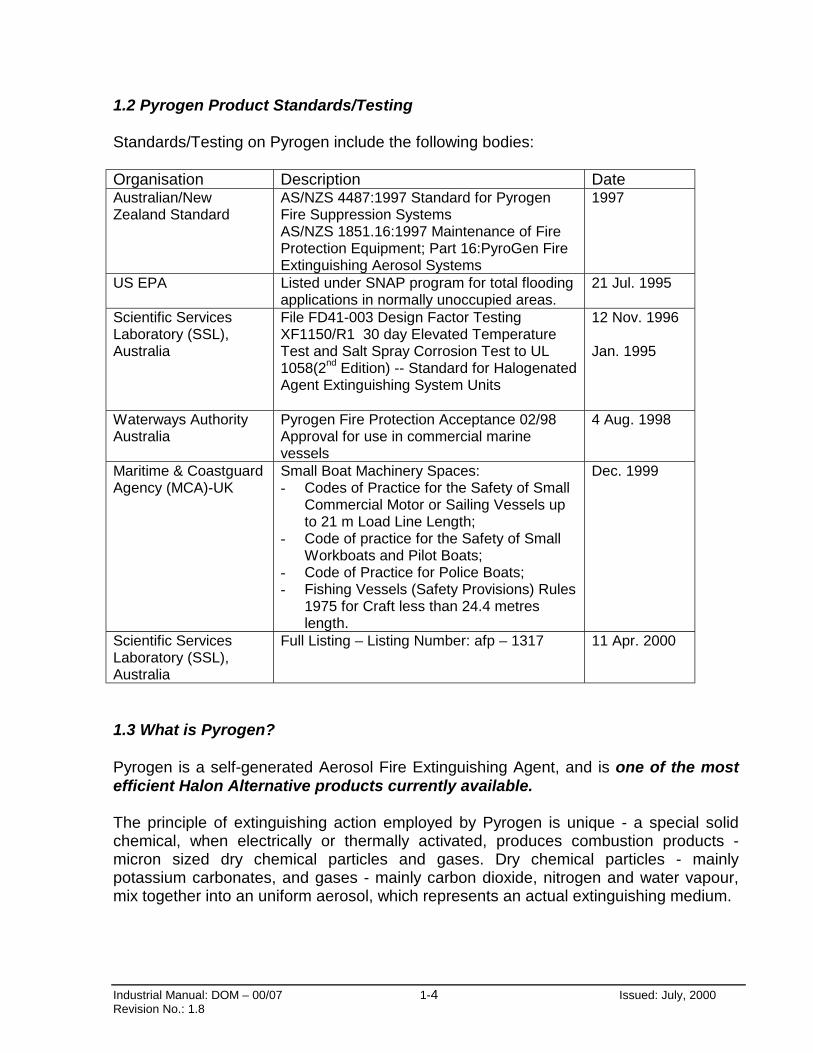
1.2 Pyrogen Product Standards/Testing
Standards/Testing on Pyrogen include the following bodies:
Organisation Description DateAustralian/NewZealand Standard
AS/NZS 4487:1997 Standard for PyrogenFire Suppression SystemsAS/NZS 1851.16:1997 Maintenance of FireProtection Equipment; Part 16:PyroGen FireExtinguishing Aerosol Systems
1997
US EPA Listed under SNAP program for total floodingapplications in normally unoccupied areas.
21 Jul. 1995
Scientific ServicesLaboratory (SSL),Australia
File FD41-003 Design Factor TestingXF1150/R1 30 day Elevated TemperatureTest and Salt Spray Corrosion Test to UL1058(2nd Edition) -- Standard for HalogenatedAgent Extinguishing System Units
12 Nov. 1996
Jan. 1995
Waterways AuthorityAustralia
Pyrogen Fire Protection Acceptance 02/98Approval for use in commercial marinevessels
4 Aug. 1998
Maritime & CoastguardAgency (MCA)-UK
Small Boat Machinery Spaces:- Codes of Practice for the Safety of Small
Commercial Motor or Sailing Vessels upto 21 m Load Line Length;
- Code of practice for the Safety of SmallWorkboats and Pilot Boats;
- Code of Practice for Police Boats;- Fishing Vessels (Safety Provisions) Rules
1975 for Craft less than 24.4 metreslength.
Dec. 1999
Scientific ServicesLaboratory (SSL),Australia
Full Listing – Listing Number: afp – 1317 11 Apr. 2000
1.3 What is Pyrogen?
Pyrogen is a self-generated Aerosol Fire Extinguishing Agent, and is one of the mostefficient Halon Alternative products currently available.
The principle of extinguishing action employed by Pyrogen is unique - a special solidchemical, when electrically or thermally activated, produces combustion products -micron sized dry chemical particles and gases. Dry chemical particles - mainlypotassium carbonates, and gases - mainly carbon dioxide, nitrogen and water vapour,mix together into an uniform aerosol, which represents an actual extinguishing medium.
Industrial Manual: DOM – 00/07 1-5 Issued: July, 2000Revision No.: 1.8
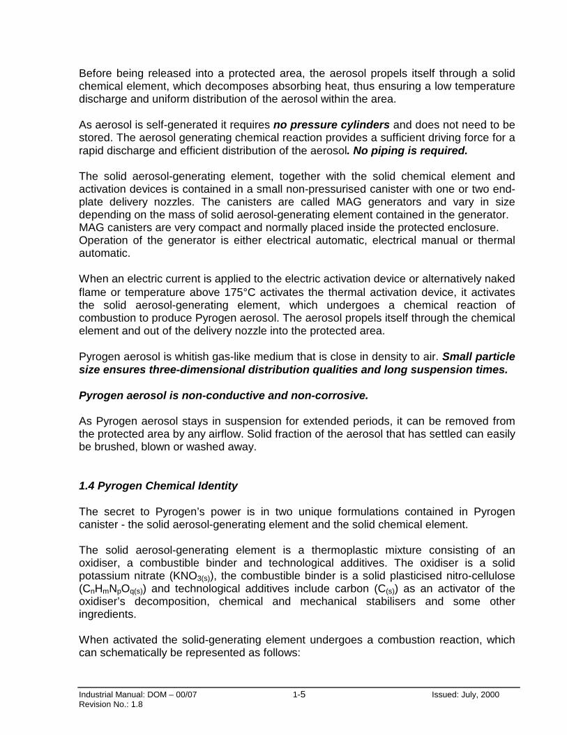
Before being released into a protected area, the aerosol propels itself through a solidchemical element, which decomposes absorbing heat, thus ensuring a low temperaturedischarge and uniform distribution of the aerosol within the area.
As aerosol is self-generated it requires no pressure cylinders and does not need to bestored. The aerosol generating chemical reaction provides a sufficient driving force for arapid discharge and efficient distribution of the aerosol. No piping is required.
The solid aerosol-generating element, together with the solid chemical element andactivation devices is contained in a small non-pressurised canister with one or two end-plate delivery nozzles. The canisters are called MAG generators and vary in sizedepending on the mass of solid aerosol-generating element contained in the generator.MAG canisters are very compact and normally placed inside the protected enclosure.Operation of the generator is either electrical automatic, electrical manual or thermalautomatic.
When an electric current is applied to the electric activation device or alternatively nakedflame or temperature above 175°C activates the thermal activation device, it activatesthe solid aerosol-generating element, which undergoes a chemical reaction ofcombustion to produce Pyrogen aerosol. The aerosol propels itself through the chemicalelement and out of the delivery nozzle into the protected area.
Pyrogen aerosol is whitish gas-like medium that is close in density to air. Small particlesize ensures three-dimensional distribution qualities and long suspension times.
Pyrogen aerosol is non-conductive and non-corrosive.
As Pyrogen aerosol stays in suspension for extended periods, it can be removed fromthe protected area by any airflow. Solid fraction of the aerosol that has settled can easilybe brushed, blown or washed away.
1.4 Pyrogen Chemical Identity
The secret to Pyrogen’s power is in two unique formulations contained in Pyrogencanister - the solid aerosol-generating element and the solid chemical element.
The solid aerosol-generating element is a thermoplastic mixture consisting of anoxidiser, a combustible binder and technological additives. The oxidiser is a solidpotassium nitrate (KNO3(s)), the combustible binder is a solid plasticised nitro-cellulose(CnHmNpOq(s)) and technological additives include carbon (C(s)) as an activator of theoxidiser’s decomposition, chemical and mechanical stabilisers and some otheringredients.
When activated the solid-generating element undergoes a combustion reaction, whichcan schematically be represented as follows:
Industrial Manual: DOM – 00/07 1-6 Issued: July, 2000Revision No.: 1.8
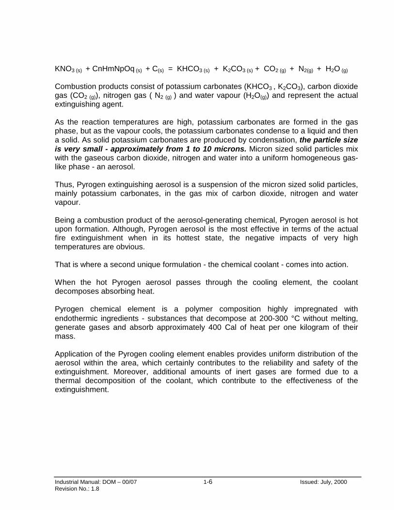
KNO3 (s) + CnHmNpOq (s) + C(s) = KHCO3 (s) + K2CO3 (s) + CO2 (g) + N2(g) + H2O (g)
Combustion products consist of potassium carbonates (KHCO3 , K2CO3), carbon dioxidegas (CO2 (g)), nitrogen gas ( N2 (g) ) and water vapour (H2O(g)) and represent the actualextinguishing agent.
As the reaction temperatures are high, potassium carbonates are formed in the gasphase, but as the vapour cools, the potassium carbonates condense to a liquid and thena solid. As solid potassium carbonates are produced by condensation, the particle sizeis very small - approximately from 1 to 10 microns. Micron sized solid particles mixwith the gaseous carbon dioxide, nitrogen and water into a uniform homogeneous gas-like phase - an aerosol.
Thus, Pyrogen extinguishing aerosol is a suspension of the micron sized solid particles,mainly potassium carbonates, in the gas mix of carbon dioxide, nitrogen and watervapour.
Being a combustion product of the aerosol-generating chemical, Pyrogen aerosol is hotupon formation. Although, Pyrogen aerosol is the most effective in terms of the actualfire extinguishment when in its hottest state, the negative impacts of very hightemperatures are obvious.
That is where a second unique formulation - the chemical coolant - comes into action.
When the hot Pyrogen aerosol passes through the cooling element, the coolantdecomposes absorbing heat.
Pyrogen chemical element is a polymer composition highly impregnated withendothermic ingredients - substances that decompose at 200-300 °C without melting,generate gases and absorb approximately 400 Cal of heat per one kilogram of theirmass.
Application of the Pyrogen cooling element enables provides uniform distribution of theaerosol within the area, which certainly contributes to the reliability and safety of theextinguishment. Moreover, additional amounts of inert gases are formed due to athermal decomposition of the coolant, which contribute to the effectiveness of theextinguishment.

Industrial Manual: DOM – 00/07 1-7 Issued: July, 2000Revision No.: 1.8
Diagram 1-1

Industrial Manual: DOM – 00/07 1-8 Issued: July, 2000Revision No.: 1.8
1.5 Pyrogen Extinguishing Action
Pyrogen aerosol is an exceptional fire suppressant.
Pyrogen extinguishing action is achieved primarily by interfering chemically with the firereaction. Two chemical mechanisms can be underlined:
1. Removal of flame propagation radicals - “chain carriers” OH, H and O in the flamezone:
As it has been mentioned above, the main component of Pyrogen aerosol - potassiumcarbonates - are formed in the gas phase. In the flame zone they dissociate producingpotassium radicals K. Potassium radicals are very active and react with “chain carriers”OH, H and O removing them from the fire zone, and as such disrupting the fire reaction.The chemical action of potassium radicals in Pyrogen is similar to that of bromineradicals in Halons and can be schematically represented as follows:
K + OH = KOH
KOH + H = K + H2O
2. Recombination of flame propagation radicals - “chain carriers” OH, H and O onaerosol particle surface:
Gaseous potassium carbonates condense to a liquid and then a solid form producing alarge number of micron sized particles. Being so small, the particles produce a largesurface area, where recombination of “chain carriers” takes place:
O + H = OH
H + OH = H2O
Secondarily, Pyrogen extinguishing action is achieved by lowering fire temperature to atemperature below which the fire reaction cannot continue (thermal cooling). Severalphysical mechanisms can be underlined:
1. Heat absorption via endothermic phase changes:
K2CO3 (s) → K2CO3 (l) → K2CO3 (g)
2. Heat absorption via endothermic decomposition reaction:
2KHCO3 (s) → K2CO3 (s) + CO2 (g) + H2O (g)
Industrial Manual: DOM – 00/07 1-9 Issued: July, 2000Revision No.: 1.8
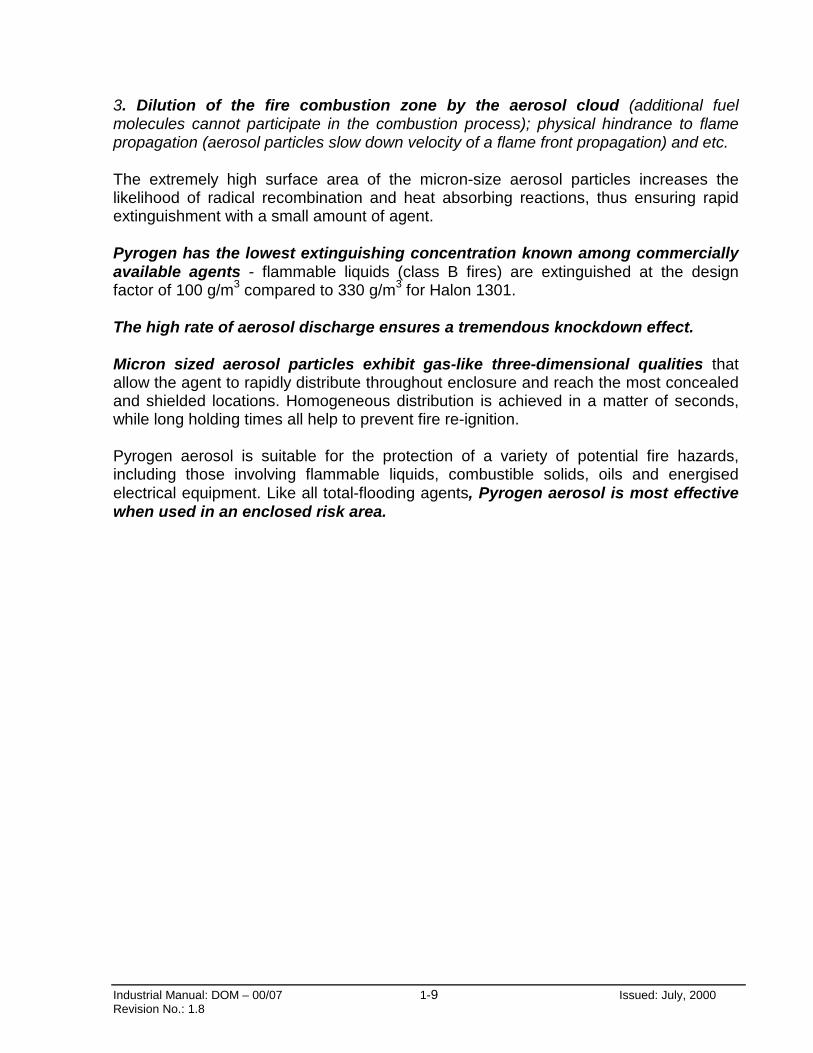
3. Dilution of the fire combustion zone by the aerosol cloud (additional fuelmolecules cannot participate in the combustion process); physical hindrance to flamepropagation (aerosol particles slow down velocity of a flame front propagation) and etc.
The extremely high surface area of the micron-size aerosol particles increases thelikelihood of radical recombination and heat absorbing reactions, thus ensuring rapidextinguishment with a small amount of agent.
Pyrogen has the lowest extinguishing concentration known among commerciallyavailable agents - flammable liquids (class B fires) are extinguished at the designfactor of 100 g/m3 compared to 330 g/m3 for Halon 1301.
The high rate of aerosol discharge ensures a tremendous knockdown effect.
Micron sized aerosol particles exhibit gas-like three-dimensional qualities thatallow the agent to rapidly distribute throughout enclosure and reach the most concealedand shielded locations. Homogeneous distribution is achieved in a matter of seconds,while long holding times all help to prevent fire re-ignition.
Pyrogen aerosol is suitable for the protection of a variety of potential fire hazards,including those involving flammable liquids, combustible solids, oils and energisedelectrical equipment. Like all total-flooding agents, Pyrogen aerosol is most effectivewhen used in an enclosed risk area.
Industrial Manual: DOM – 00/07 1-10 Issued: July, 2000Revision No.: 1.8
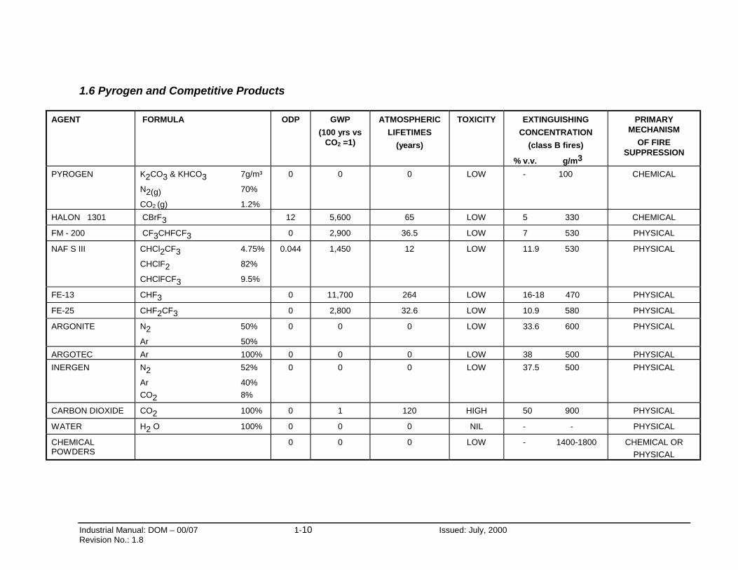
1.6 Pyrogen and Competitive Products
AGENT FORMULA ODP GWP
(100 yrs vsCO2 =1)
ATMOSPHERIC
LIFETIMES
(years)
TOXICITY EXTINGUISHING
CONCENTRATION
(class B fires)
% v.v. g/m3
PRIMARYMECHANISM
OF FIRESUPPRESSION
PYROGEN K2CO3 & KHCO3 7g/m³
N2(g) 70%
CO2 (g) 1.2%
0 0 0 LOW - 100 CHEMICAL
HALON 1301 CBrF3 12 5,600 65 LOW 5 330 CHEMICAL
FM - 200 CF3CHFCF3 0 2,900 36.5 LOW 7 530 PHYSICAL
NAF S III CHCl2CF3 4.75%
CHClF2 82%
CHClFCF3 9.5%
0.044 1,450 12 LOW 11.9 530 PHYSICAL
FE-13 CHF3 0 11,700 264 LOW 16-18 470 PHYSICAL
FE-25 CHF2CF3 0 2,800 32.6 LOW 10.9 580 PHYSICAL
ARGONITE N2 50%
Ar 50%
0 0 0 LOW 33.6 600 PHYSICAL
ARGOTEC Ar 100% 0 0 0 LOW 38 500 PHYSICAL
INERGEN N2 52%
Ar 40%
CO2 8%
0 0 0 LOW 37.5 500 PHYSICAL
CARBON DIOXIDE CO2 100% 0 1 120 HIGH 50 900 PHYSICAL
WATER H2 O 100% 0 0 0 NIL - - PHYSICAL
CHEMICALPOWDERS
0 0 0 LOW - 1400-1800 CHEMICAL OR
PHYSICAL

Industrial Manual: DOM – 00/07 1 - 11 Issued: July 2000Revision No.: 1.8
1.7 Pyrogen Applications and Limitations
Pyrogen may be used as a total flooding fire suppressant for unoccupied andnormally unoccupied areas to fight fires of classes A, B, C, E and F.
For class C fires consideration should be given to the use of vapour detection, explosionventing or explosion suppression systems where an explosion potential may exist, owingto the possible presence of gaseous, volatile or atomised fuels either before or followinga fire. It may be dangerous, under certain conditions to extinguish a burning jet offlammable gases without first shutting off its supply.
The design factor required to suppress normal fires involving flammable gases andliquids at atmospheric pressure shall apply if it can be shown that a potentially explosiveatmosphere cannot exist in the enclosure either before or as a result of the fire.
The minimum design factor for Classes C, E and F fire hazards shall be determined bytest as part of a listing program.
An unoccupied area is an area that is not occupied by humans under any conditions.
A normally unoccupied area is an area that is not occupied by humans under normalcircumstances but may be entered occasionally for brief periods.
Total Flooding Applications: May be used where the hazard is within an enclosure thatwill permit the establishment of the required concentration and the maintenance of thatconcentration for the required period, for example, for-
• Marine: machinery spaces, engine rooms.
• Transport: engine compartments.
• Aviation: aircraft dry-bays, cargo compartments, engine nacelles.
• Industrial: enclosed flammable liquid storage, storage tanks & processing areas.
enclosures such as rooms, warehouses, garages, control rooms, engine rooms, vaults.
enclosed machines, data processing equipment, mining equipment.
enclosed electrical hazards such as transformers, control cubicles, switchboards, circuit breakers & rotating equipment.
security boxes (ATM, tender & post boxes) & remote locations.

Industrial Manual: DOM – 00/07 1 - 12 Issued: July 2000Revision No.: 1.8
Pre-engineered Packaged Systems: Designed and tested for a specific application.
• Modular package system: up to 10 m3.
• Four wheel drive package system: up to 3 m3.
• Marine package system: up to 20 m3 with dedicated electrical manual release panel.
Limitations of Pyrogen Systems:
Pyrogen systems are not suitable for fires involving the following:
• Certain chemicals or mixtures of chemicals such as cellulose nitrate and gunpowder,which are capable of rapid oxidation in the absence of air.
• Reactive metals such as sodium, potassium, magnesium, titanium, zirconium,uranium, and plutonium.
• Metal hydrides or metal amides.
• Chemicals capable of undergoing auto-thermal decomposition such as certainorganic peroxides and hydrazine.
• Pyrophoric materials such as white phosphorous or metal-organic compounds.
• Oxidising agents such as nitric oxides and fluorine.
Non Enclosed and Local Applications
Where a fire hazard requires a local application, due to the protected area being anopen space or one with high leakage rates, special application and engineering of thePyrogen product will be required. In these instances the local main Pyrogen officeshould be contacted.
Electrical Machinery/Equipment:
In the event of fire due to electrical hazards, power to the electricalmachinery/equipment must be cut-off prior to operation of the fire protectionsystem for effective suppression of fire.

Industrial Manual: DOM – 00/07 1 - 13 Issued: July 2000Revision No.: 1.8
1.8 Pyrogen Safety Data
Visibility: Pyrogen is intended to be used in normally unoccupied areas principally dueto the high obscuration caused by the aerosol during and after discharge.
Oxygen Levels: Pyrogen chemically attacks the fire, breaking the flame chain reaction. Itdoes not extinguish fires by oxygen depletion. After discharge, oxygen levels willremain at or about normal.
Toxicity: Inadvertent exposure to Pyrogen aerosol should always be avoided.Toxicological information refers to an inadvertent exposure to the aerosol in the event ofaccidental discharge in a non-fire situation.
The main ingredients of the Pyrogen aerosol are solid potassium carbonates, nitrogengas, carbon dioxide gas and water vapour. At normal extinguishing concentrations theseproducts present little health hazard to personnel. However, small amounts of potentiallyhazardous by-products of the aerosol-generating combustion reaction, such as carbonmonoxide and nitrogen oxides will be produced. Their actual concentrations depend onPyrogen design factor used and type of enclosure under protection. Their toxicologicalcharacteristics depend upon the actual concentrations achieved and duration ofexposure.
Exposure to a Pyrogen design factor of 100 g/m3, which is typical for class B firesin total flooding applications, for up to 5 minutes, is normally considered torepresent a minor risk to personnel and may cause only moderate local irritationof the upper respiratory tract and to the eyes.
Post Fire Exposure: One of the key advantages of Pyrogen over Halon 1301 and oversome of the replacement agents available, is that Pyrogen does not produce toxicand highly corrosive halogen acids when exposed to fire or hot surfaces. Safetyrequirements dictate, however, that unnecessary exposure to post-fire atmospheresshould be avoided. CAUTION! Venting of the post-fire atmosphere should be to anopen-air area, where possible, to prevent the inadvertent exposure of personnelto any combustion products of the fire and aerosol-generating reaction.
Thermal Hazard: There is a potential hazard of high temperatures (250°C+) of Pyrogenaerosol at the end-plate nozzle, but within the minimum clearance (Xm) from thedischarge nozzle as specified for every type of MAG generator, the temperature doesnot exceed 75°C. Those distances should be observed during installation. For furtherinformation please see Section 2.10.
Immediately after discharge the generators can be hot, therefore, protective glovesshould be worn before handling generators up to 15 minutes after discharge.
Industrial Manual: DOM – 00/07 1 - 14 Issued: July 2000Revision No.: 1.8
Hot Work: As naked flame or prolonged exposure to temperatures above 400°C maycause activation of the generators, hot work must not be carried out within thevicinity of any generator. If so they shall be removed prior to any hot work beingcarried out.
Thermal automatic operation: Pyrogen thermal initiating device (fire conductingcord) may be used in unoccupied areas only.
Re-entry: Following the use of Pyrogen, personnel should not enter the protectedarea until it has been thoroughly ventilated. Exposure to the fire by-products andextinguishant mixture should be avoided. Wearing a respirator or other available meansof protection may be required should it be necessary to enter the area before it is fullyventilated.
Clean-up: Following a system discharge the aerosol particles that have settled shouldbe vacuumed, blown, brushed or, if appropriate, washed away. Protective gloves andgoggles should be worn. A respirator or mask may be required.
Large amounts of residue that is allowed to absorb moisture may become electricallyconductive over a period of time.
Dangerous Goods Classification: Pyrogen is a Class 4.1 article in accordance with theUnited Nations Dangerous Goods Classification Code.
CoSHH Statement: A by-product of Pyrogen aerosol-generating combustion reactionare fine potassium carbonate particles, small enough to be respirated by persons notwearing RPE. There are no known toxicological long term effects of these solublemicron sized particles, and physiological effects of deep lung penetration are usually aconcern for insoluble sub-micron particles as they can interfere with pulmonaryfunctions.
However, there are clear European guidelines controlling the exposure of persons tofine particles, irrespective of their nature. Further information is available in BS EN481:1993 & BS EN 451:1993, and in CoSHH supportive documents EH40/98 & EH44and MDHS 14/2.
Noise. The sound output & frequency at the time of activation and during discharge issimilar to that produced by other extinguishing agents. Consequently, no specificprecautions need to be taken.

Industrial Manual: DOM – 00/07 1 - 15 Issued: July 2000Revision No.: 1.8
1.9 Pyrogen Environmental Characteristics
Pyrogen does not affect earth’s ozone layer, since it does not contain chlorine orbromine in its molecular structure.
Ozone Depleting Potential (ODP) is a calculated ozone depletion per unit mass ofmaterial released relative to a standard, normally CFC-11 (CCl3F).
Ozone Depleting Potential (ODP) of Pyrogen is zero.
Contribution of Pyrogen to global warming is negligible, since the only one componentthat could contribute to global warming - carbon dioxide - is present in minor quantitiesat normal extinguishing concentrations.
Global Warming Potential (GWP) is a calculated change is warming resulting from theemission of a unit mass of a chemical relative to that of a reference. In the past CFC-11was often used as a reference; carbon dioxide is now typically used.
The GWP depends on three variables:
1) the integrated infrared radiation absorption spectrum band strength.
2) the location of the infrared bands; and
3) the atmospheric lifetime
Global Warming Potential (GWP) of Pyrogen relatively to carbon dioxide is zero.
Industrial Manual: DOM – 00/07 1 - 16 Issued: July 2000Revision No.: 1.8
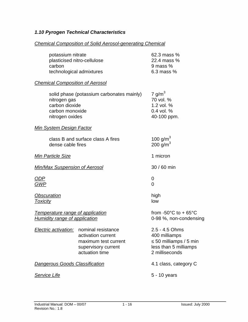
1.10 Pyrogen Technical Characteristics
Chemical Composition of Solid Aerosol-generating Chemical
potassium nitrate 62.3 mass %plasticised nitro-cellulose 22.4 mass %carbon 9 mass %technological admixtures 6.3 mass %
Chemical Composition of Aerosol
solid phase (potassium carbonates mainly) 7 g/m3
nitrogen gas 70 vol. %carbon dioxide 1.2 vol. %carbon monoxide 0.4 vol. %nitrogen oxides 40-100 ppm.
Min System Design Factor
class B and surface class A fires 100 g/m3
dense cable fires 200 g/m3
Min Particle Size 1 micron
Min/Max Suspension of Aerosol 30 / 60 min
ODP 0GWP 0
Obscuration highToxicity low
Temperature range of application from -50°C to + 65°CHumidity range of application 0-98 %, non-condensing
Electric activation: nominal resistance 2.5 - 4.5 Ohmsactivation current 400 milliampsmaximum test current ≤ 50 milliamps / 5 minsupervisory current less than 5 milliampsactuation time 2 milliseconds
Dangerous Goods Classification 4.1 class, category C
Service Life 5 - 10 years

Industrial Manual: DOM – 00/07 2-0 Issued: July 2000Revision No.: 1.8
AEROSOL FIRE SUPPRESSION SYSTEM
SECTION 2:
SYSTEM DESIGN FOR TOTAL FLOODING APPLICATION

Industrial Manual: DOM – 00/07 2-1 Issued: July 2000Revision No.: 1.8
SECTION 2. SYSTEM DESIGN FOR TOTAL FLOODING APPLICATIONS
2.1 General
The Pyrogen system of aerosol generators distributed within the risk eliminates thecomplications associated with traditional gaseous agent systems. Pyrogen does notrequire pressurised cylinders of liquefied gas, traditional pipe and nozzlenetworks, or engineered hydraulic calculations to determine nozzle orifices.
The Installer only needs to determine the size and number of Pyrogen generatorsrequired as well as their location within the enclosure. A System Design ApprovalCertificate has been included in Appendix A (Form 1) which gives a step by step guideon how to carry out these simple design calculations.
2.2 Design Methodology
The outline for the design of a Pyrogen total flooding fire suppression system generallyinvolves the following at a minimum:
1. Identify all possible hazards within the protected enclosure. Please refer toSection 1.7 for the list of fire hazards/fuel types that are unsuitable for use withPyrogen. For fire hazards/fuel types not covered in Section 1.7, please refer thequery to an Authorised Pyrogen representative.
2. Identify possible points of agent loss within the protected enclosure
3. Determine volume of the protected enclosure. It may be necessary to derive the netprotected volume in enclosures containing large impermeable structures/machineryIdentify if the required coverage extends to the ceiling void and/or raised floor anddetermine the protected volume for these.
4. Calculate the quantity of agent required .for the hazard and fuel type within theenclosure. Factors such as non-closable openings, forced ventilation, low altitude,low temperature and other conditions may affect the quantity of agent required.
5. Select the model and quantity of generators required to achieve the minimum designquantity.

Industrial Manual: DOM – 00/07 2-2 Issued: July 2000Revision No.: 1.8
2.3 Design Factor
Pyrogen design calculations refer not to the design concentration of the actualextinguishing agent - aerosol, but to the design factor, which is the mass of solidaerosol-generating element per unit of enclosure volume required to extinguish aspecific type of fire, including a safety factor.
Pyrogen design factor is expressed in g/m3.
Pyrogen minimum design factor for Class B fires, involving flammable liquids such aspetrol, diesel, hydraulic oil and automotive distillate is 100 g/m3.
Pyrogen minimum design factor for Class A surface fires, involving non-smoulderingcombustible solids such as wood, textile and ordinary plastics is 100 g/m3.
Pyrogen minimum design factor for Class A non-surface fires, involving dense cables is200 g/m3.
Advice from Pyrogen Corporation or authorised Pyrogen Representative should besought for any fire/fuel type not covered by the above minimum design factors.
2.4 Design Quantity
For normal total flooding applications based on a static volume enclosure with allopenings sealed and all ventilation systems shut down prior to Pyrogen discharge, thetotal flooding quantity is determined as follows:
Total Flooding Quantity (g) = Design Factor (g/m3) x Enclosure Volume (m3).
Total Flooding Quantity refers to the total mass of solid aerosol-forming compositionrequired to suppress fire in a given volume, including safety factor.
2.5 Number of MAG generators
For normal total flooding applications based on a static volume enclosure with allopenings sealed and all ventilation systems shut down prior to Pyrogen discharge, thenumber of MAG generators is determined as follows:
Total Flooding Quantity (g) [as calculated in Section 2.4]Number of MAG = The mass of the solid aerosol-forming x efficiency Coefficient
composition in one MAG generator of MAG generator

Industrial Manual: DOM – 00/07 2-3 Issued: July 2000Revision No.: 1.8
The above calculation refers to the same size of MAG generators only. However,different sizes of MAG generators may be selected, in which case the total mass ofaerosol-forming element shall be not less than the Total Flooding Quantity.
Please refer to Section 2.6 for a complete list of Pyrogen MAG generators available.
The type of MAG generator selected is typically based on several considerations asfollows:
1. Height of Protected Enclosure: MAG generators chosen must be appropriate for theheight of the protected enclosure. Please refer to Section 2.10 for the heightlimitation list.
2. Minimum Clearance: minimum clearance is an essential criteria to ensure that thepossibility of damage due to heat of the discharge is minimised. Please refer toSection 2.10.
3. Distribution of Aerosol: Although Pyrogen aerosol has the three-dimensionaldistribution of a gas, the even and rapid attainment of the minimum extinguishingconcentration throughout the protected enclosure would obviously be desirable. E.g.In applications such as the protection of cable ducts and trenches, which aretypically long and narrow, it would be appropriate to select several smaller units andspread them out evenly along the protected volume although one large unit may fulfilthe agent quantity requirement.
4. Mounting Locations: Certain protected enclosures may have very specificpermissible mounting locations. This may influence the quantity and orientation ofthe units selected.
5. Cost Factors: The price/m3 of the different MAG units may differ. The best costoption without sacrificing technical requirements are the elements of good design.

Industrial Manual: DOM – 00/07 2-4 Issued: July 2000Revision No.: 1.8
2.6 Pyrogen Range
Pyrogen comes in a form of small non-pressurised canisters with one or two end-plate delivery nozzles. The canisters are calledMAG generators and vary in size depending on the mass of solid aerosol-generating element contained in the generator.Technical parameters of the current range of MAG generators are as follows:
Parameter MAG 02 1 2 3 4 5 11 12 13 14 15 16 17
1. Mass of generator, g 125 650 750 1,000 4,000 2,200 11,000 13,500 19,000 37,000 40,000 50,000 58,000
2. Mass of aerosol-forming element, g
20 60 100 200 1,000 500 1,500 2,200 3,500 5,500 6,500 8,500 10,000
3. Efficiency Coefficient ofunit
1 1 1 1 1 1 0.8 0.773 0.773 0.773 0.773 0.773 0.773
4. Max protected volumem3, class B fires
0.2 0.6 1 2 10 5 12 17 27 46 50 65 85
5. Nozzle outlet bi mono mono mono bi mono mono mono mono mono mono mono mono
6. Length of generator,B (mm)
120 75 90 135 375 200 180 245 235 260 175 225 285
7. Diameter of generator,A (mm)
30 75 75 75 95 95 245 245 305 400 490 490 490
8. Discharge time, s <3.5 <3.5 <6.0 <7.5 <10.0 <7.5 <10.0 <10.0 <10.0 <10.0 <10.0 <10.0 <10.0
1 Based on Design Factor of 100g/m3

ustri anual: DOM – 00/07 2-5 visio o.: 1.8
70
50 mm
Diagram 2-1: Typical ConstructioMag-11, Mag-12, Mag-13, Mag-14,
FRONT SIDE
A
Issued: July 2000
(see tablepage 2.4)
B(see tablepage 2.4)
n of Pyrogen GeneratorsMag-15, Mag-16 & Mag-17
al Mn N
IndRe
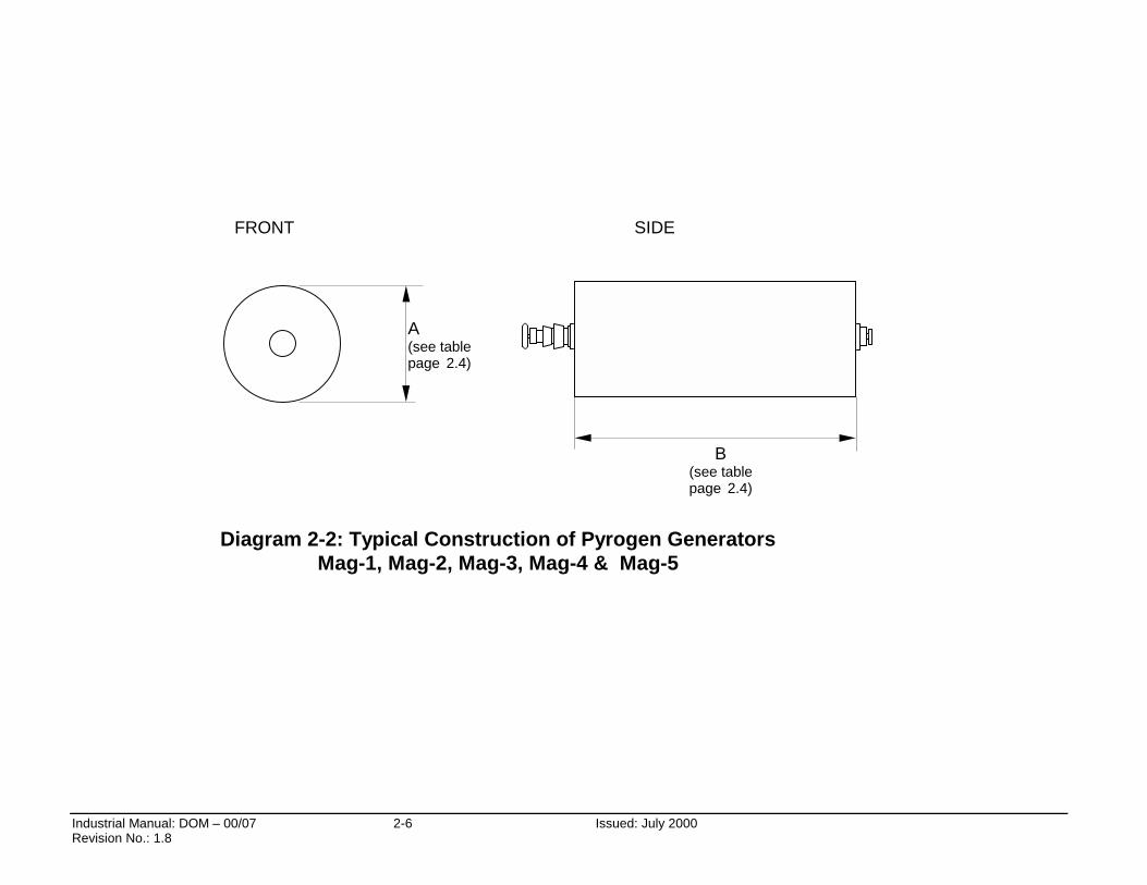
Industrial Manual: DOM – 00/07 Revision No.: 1.8
A(see tablepage 2.4)
B(see tablepage 2.4)
Diagram 2-2: Typical Construction of Pyrogen GeneratorsMag-1, Mag-2, Mag-3, Mag-4 & Mag-5
FRONT SIDE
2-6
Issued: July 2000
Industrial Manual: DOM – 00/07 2-7 Issued: July 2000Revision No.: 1.8
2.7 Minimum Holding Time
Upon Pyrogen discharge a minimum holding time of 3 minutes should be allowed, forfires involving flammable liquids (class B fires) and non-smouldering combustible solids(class A surface fires).
For fires involving electrical cables and smouldering solids the minimum holdingtime should be extended to 10 minutes.
2.8 Enclosure Requirements
The area of non-closable openings shall be kept to a minimum. The presence ofunclosable openings in the ceiling should be avoided. The total area of unclosableopenings should not exceed 1 % of the total area of the protected enclosure.
Air-handling systems serving the protected area should generally be shut downor isolated by dampers.
Any services within the enclosure, such as fuel valves and pumps, heating appliancesand others which if left running would impair the efficiency of Pyrogen, shall be shutdown prior to or simultaneously with the release of the extinguishant.
For tight enclosures, venting of an enclosure may be necessary to relieve pressurebuild-up due to the discharge of large quantities of extinguishant. For calculations todetermine the minimum area necessary for free venting, the following formula may beused:
X = 0.3 x Q x ν/ {∆ P x ν’}0.5, where …(Eq. 2.1)
X = free venting area , in m2;Q = Pyrogen discharge rate, in kg/s (should be taken as a total flooding quantity overdischarge time);ν - specific vapour volume of Pyrogen at 101 kPa absolute pressure and enclosuretemperature, in m3 /kg ( 0.7 at 50 °C);ν‘ - specific vapour volume of Pyrogen/ air mixture being vented at 101 kPa absolutepressure and enclosure temperature, in m3 /kg ( 0.89 at 50 °C);∆ P - pressure drop across a venting area, in kPa (normally 0.6 for strong enclosures,0.4 for medium strength enclosures)
Taken ∆P = 0.6 kPa, the above formula can be simplified as follows:
X = 0.287 Q = 0.287 m/ t, where …(Eq. 2.1.1)m – mass of aerosol-forming composition, kgt – discharge time, s
Industrial Manual: DOM – 00/07 2-8 Issued: July 2000Revision No.: 1.8
2.9 Design Quantity Calculations - Special Conditions
The Pyrogen design quantity shall be adjusted to compensate for any special conditionssuch as un-closable openings, forced ventilation, altitude substantially below sea level,temperatures substantially below 0°C or other causes of extinguishant loss.
Sealed Enclosures
Most applications of Pyrogen are based on a static volume enclosure with all openingssealed and all ventilation systems shut down prior to Pyrogen discharge.
Often the ventilation system does not shut down but instead is dampened to allowrecirculating air (without make-up air) to continue cooling equipment and promote themixing of Pyrogen aerosol and air. Total flooding quantities are still based on a staticvolume for these applications. However, in this instance, it may be necessary to includethe volume of the ventilation ductwork in addition to the volume of the enclosure
Effects of Altitude
Unlike gaseous extinguishants, where volumetric concentrations are used for designcalculations, Pyrogen total flooding applications refer to mass concentration only. Assuch, altitude has no effect on the design factor calculations. However, the parameterthat may be affected by altitude is the extinguishants’ gas-like three-dimensionaldistribution in a given enclosure.
At elevations above sea level, Pyrogen aerosol expands to a greater specific volumebecause of the reduced atmospheric pressure. Hence, a system designed for sea-levelconditions will provide, at the same design factor, a higher coverage at elevations abovesea level. However, a reduction in extinguishant quantity is not recommended as it mayresult in lower extinguishant performance.
For elevations below sea level, Pyrogen may compress to a lessor specific volumebecause of increased atmospheric pressure. This may result in lower coveragecompared to that achieved under sea-level conditions, the likelihood of this should below due to a high velocity and elevated temperature of aerosol being released.
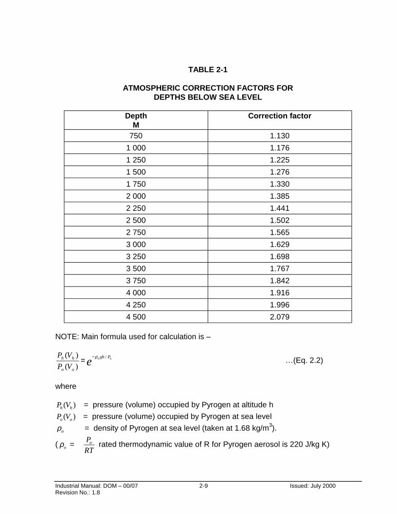
At elevations substantially below sea level, the quantity indicated at sea-level conditionscould be increased to compensate for a lower coverage. Design factor determined atsea level shall be multiplied by correction factor given in Table 2-1 to obtain correctvalues.
Industrial Manual: DOM – 00/07 2-9 Issued: July 2000Revision No.: 1.8
TABLE 2-1
ATMOSPHERIC CORRECTION FACTORS FORDEPTHS BELOW SEA LEVEL
DepthM
Correction factor
750 1.130
1 000 1.176
1 250 1.225
1 500 1.276
1 750 1.330
2 000 1.385
2 250 1.441
2 500 1.502
2 750 1.565
3 000 1.629
3 250 1.698
3 500 1.767
3 750 1.842
4 000 1.916
4 250 1.996
4 500 2.079
NOTE: Main formula used for calculation is –
e oo Pgh
oo
hh
VP
VP /
)(
)( ρ−= …(Eq. 2.2)
where
)( hh VP = pressure (volume) occupied by Pyrogen at altitude h
)( oo VP = pressure (volume) occupied by Pyrogen at sea level
oρ = density of Pyrogen at sea level (taken at 1.68 kg/m3).
( oρ = RT
Po rated thermodynamic value of R for Pyrogen aerosol is 220 J/kg K)
Industrial Manual: DOM – 00/07 2-10 Issued: July 2000Revision No.: 1.8
Effects of Temperature
Similar to altitude, temperature has no effect on Pyrogen design factor calculations, butit affects the extinguishant’s spatial distribution.
At elevated temperatures, Pyrogen expands to a greater specific volume. A systemdesigned for standard conditions will therefore develop, at the same design factor, ahigher distribution at elevated temperatures. Reduction in quantity of extinguishant is,however, not recommended, the reason being as explained above for the effects ofaltitude.
At lower temperatures, Pyrogen may compress to a lessor specific volume. This mayresult in lower coverage compared to that achieved under standard temperatureconditions. The likelihood of this should be low due to a high velocity and the elevatedtemperature of aerosol being released.
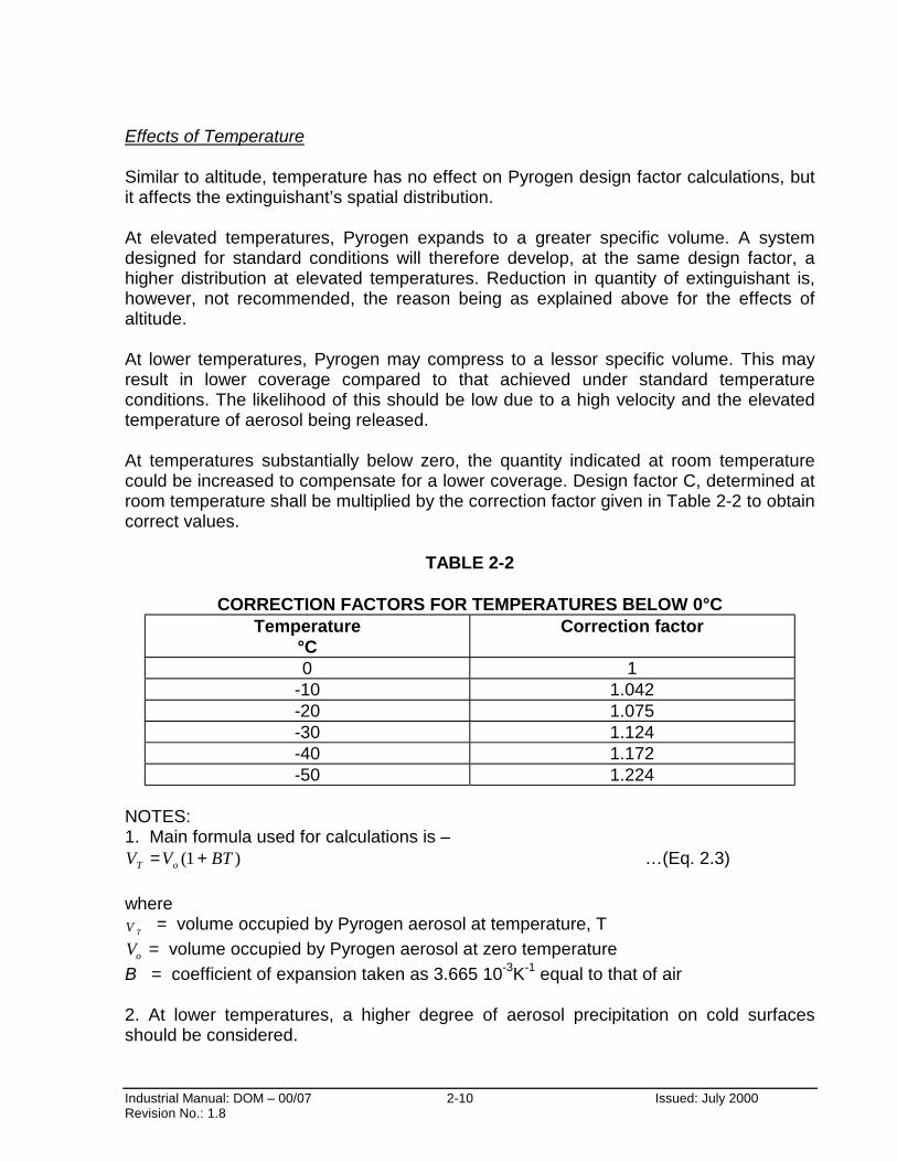
At temperatures substantially below zero, the quantity indicated at room temperaturecould be increased to compensate for a lower coverage. Design factor C, determined atroom temperature shall be multiplied by the correction factor given in Table 2-2 to obtaincorrect values.
TABLE 2-2
CORRECTION FACTORS FOR TEMPERATURES BELOW 0°CTemperature
°CCorrection factor
0 1-10 1.042-20 1.075-30 1.124-40 1.172-50 1.224
NOTES:1. Main formula used for calculations is –
)1( BTVV oT += …(Eq. 2.3)
where
TV = volume occupied by Pyrogen aerosol at temperature, T
oV = volume occupied by Pyrogen aerosol at zero temperature
B = coefficient of expansion taken as 3.665 10-3K-1 equal to that of air
2. At lower temperatures, a higher degree of aerosol precipitation on cold surfacesshould be considered.
Industrial Manual: DOM – 00/07 2-11 Issued: July 2000Revision No.: 1.8
Effects Of Ventilation
Pyrogen is recommended for applications in enclosures in which all ventilationsystems are shut down prior to extinguishant discharge.
However, the possibility of Pyrogen discharge into a total flooding enclosure that isventilated should also be considered. In such enclosures, some extinguishant will belost with the ventilating air. Assuming that ventilation must continue during and afterdischarge, a greater amount of extinguishant is required to develop a givenconcentration. Also, to maintain the concentration at a given level requires continuousextinguishant discharge for the duration of the soaking period.
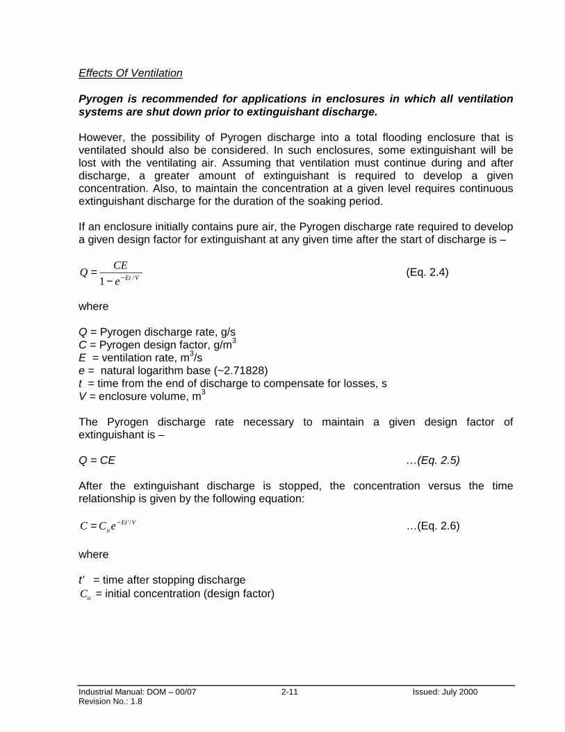
If an enclosure initially contains pure air, the Pyrogen discharge rate required to developa given design factor for extinguishant at any given time after the start of discharge is –
VEte
CEQ
/1 −−= (Eq. 2.4)
where
Q = Pyrogen discharge rate, g/sC = Pyrogen design factor, g/m3
E = ventilation rate, m3/se = natural logarithm base (~2.71828)t = time from the end of discharge to compensate for losses, sV = enclosure volume, m3
The Pyrogen discharge rate necessary to maintain a given design factor ofextinguishant is –
Q = CE …(Eq. 2.5)
After the extinguishant discharge is stopped, the concentration versus the timerelationship is given by the following equation:
VEtoeCC /'−= …(Eq. 2.6)
where
t’ = time after stopping discharge
oC = initial concentration (design factor)
Industrial Manual: DOM – 00/07 2-12 Issued: July 2000Revision No.: 1.8
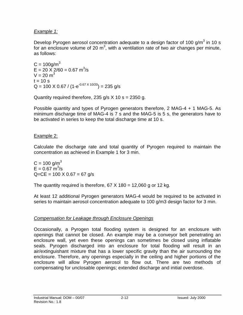
Example 1:
Develop Pyrogen aerosol concentration adequate to a design factor of 100 g/m3 in 10 sfor an enclosure volume of 20 m3, with a ventilation rate of two air changes per minute,as follows:
C = 100g/m3
E = 20 X 2/60 = 0.67 m3/sV = 20 m3
t = 10 sQ = 100 X 0.67 / (1-e-0.67 X 10/20) = 235 g/s
Quantity required therefore, 235 g/s X 10 s = 2350 g.
Possible quantity and types of Pyrogen generators therefore, 2 MAG-4 + 1 MAG-5. Asminimum discharge time of MAG-4 is 7 s and the MAG-5 is 5 s, the generators have tobe activated in series to keep the total discharge time at 10 s.
Example 2:
Calculate the discharge rate and total quantity of Pyrogen required to maintain theconcentration as achieved in Example 1 for 3 min.
C = 100 g/m3
E = 0.67 m3/sQ=CE = 100 X 0.67 = 67 g/s
The quantity required is therefore, 67 X 180 = 12,060 g or 12 kg.
At least 12 additional Pyrogen generators MAG-4 would be required to be activated inseries to maintain aerosol concentration adequate to 100 g/m3 design factor for 3 min.
Compensation for Leakage through Enclosure Openings
Occasionally, a Pyrogen total flooding system is designed for an enclosure withopenings that cannot be closed. An example may be a conveyor belt penetrating anenclosure wall, yet even these openings can sometimes be closed using inflatableseals. Pyrogen discharged into an enclosure for total flooding will result in anair/extinguishant mixture that has a lower specific gravity than the air surrounding theenclosure. Therefore, any openings especially in the ceiling and higher portions of theenclosure will allow Pyrogen aerosol to flow out. There are two methods ofcompensating for unclosable openings; extended discharge and initial overdose.

Industrial Manual: DOM – 00/07 2-13 Issued: July 2000Revision No.: 1.8
Extended discharge involves a continuous addition of Pyrogen at a rate, which willcompensate for leakage out of the enclosure during the required soaking period. Theinitial overdose method provides for an adequate overdose of Pyrogen to assure a pre-established minimum of extinguishant at the end of the desired soaking period.
IMPORTANT! CARE SHOULD BE TAKEN TO PREVENT ANY POSSIBILITY OFPERSONNEL EXPOSURE TO THE HIGH INITIAL CONCENTRATIONS OFPYROGEN AEROSOL.
Estimation of Pyrogen leakage through enclosure openings during the soaking period,and hence, the amount of extinguishant required for compensation, could be effected byusing the following equation:
)1()( /2 VRTAGto emtm −−= …(Eq. 2.7)
where
m(t) = mass of Pyrogen leakage out of the enclosure through the openings by the endof the soaking period, in kilograms
om = initial mass of Pyrogen discharged into the enclosure, in kilograms
e = natural logarithm base (~2.71828)R = gas constant, 220J/kg K for PyrogenT = ambient temperature inside the enclosure after Pyrogen discharge, in K (323 K(50°C) as shown by practical testsA = leakage area, in m2
t = soaking period, in sV = volume of the enclosure, in m3
G = geometric constant (see Equation 2.10)
NOTE: Equation 2.7 has been derived based on the following general formulas andassumptions:
(a) PGAdt
dm ∆= ρ2 …(Eq. 2.8)
where
m = mass flow in kilogramsG = geometric constant (see Equation 2.10)A = leakage area in m2
ρ = density in kg/m3
P∆ = pressure difference across the flow path (excessive pressure build up due to thedischarge of Pyrogen) in Pa.
(b) Ideal gas behaviour of Pyrogen aerosol, and as such applicability of the ideal gasequation –
Industrial Manual: DOM – 00/07 2-14 Issued: July 2000Revision No.: 1.8
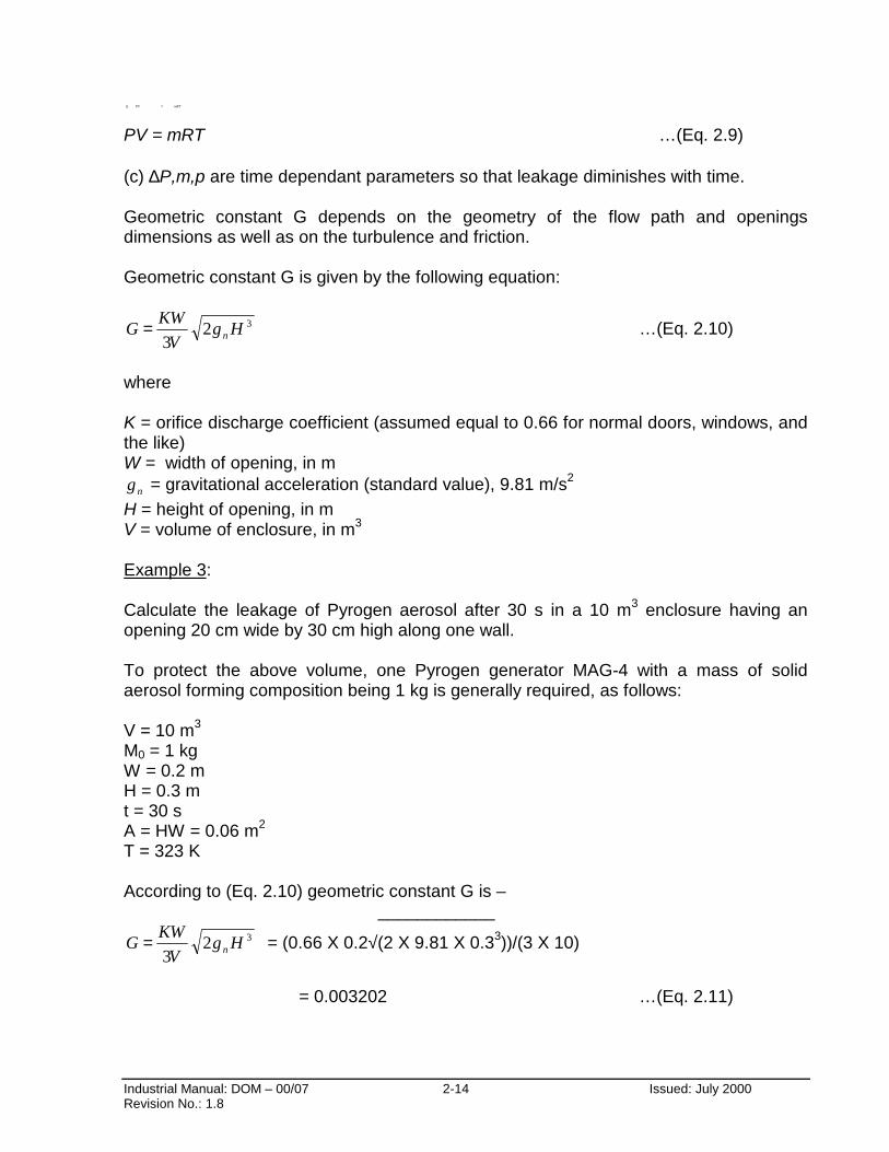
PV = mRT …(Eq. 2.9)
(c) ∆P,m,p are time dependant parameters so that leakage diminishes with time.
Geometric constant G depends on the geometry of the flow path and openingsdimensions as well as on the turbulence and friction.
Geometric constant G is given by the following equation:
323
HgV
KWG n= …(Eq. 2.10)
where
K = orifice discharge coefficient (assumed equal to 0.66 for normal doors, windows, andthe like)W = width of opening, in m
ng = gravitational acceleration (standard value), 9.81 m/s2
H = height of opening, in mV = volume of enclosure, in m3
Example 3:
Calculate the leakage of Pyrogen aerosol after 30 s in a 10 m3 enclosure having anopening 20 cm wide by 30 cm high along one wall.
To protect the above volume, one Pyrogen generator MAG-4 with a mass of solidaerosol forming composition being 1 kg is generally required, as follows:
V = 10 m3
M0 = 1 kgW = 0.2 mH = 0.3 mt = 30 sA = HW = 0.06 m2
T = 323 K
According to (Eq. 2.10) geometric constant G is – ____________
323
HgV
KWG n= = (0.66 X 0.2√(2 X 9.81 X 0.33))/(3 X 10)
= 0.003202 …(Eq. 2.11)
mRTPV =∆
Industrial Manual: DOM – 00/07 2-15 Issued: July 2000Revision No.: 1.8
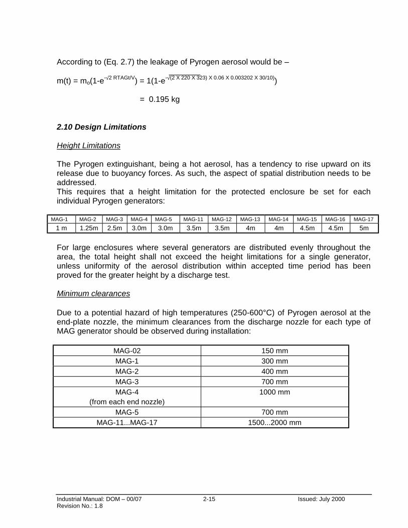
According to (Eq. 2.7) the leakage of Pyrogen aerosol would be – _______m(t) = mo(1-e-√2 RTAGt/V) = 1(1-e-√(2 X 220 X 323) X 0.06 X 0.003202 X 30/10))
= 0.195 kg
2.10 Design Limitations
Height Limitations
The Pyrogen extinguishant, being a hot aerosol, has a tendency to rise upward on itsrelease due to buoyancy forces. As such, the aspect of spatial distribution needs to beaddressed.This requires that a height limitation for the protected enclosure be set for eachindividual Pyrogen generators:
MAG-1 MAG-2 MAG-3 MAG-4 MAG-5 MAG-11 MAG-12 MAG-13 MAG-14 MAG-15 MAG-16 MAG-17
1 m 1.25m 2.5m 3.0m 3.0m 3.5m 3.5m 4m 4m 4.5m 4.5m 5m
For large enclosures where several generators are distributed evenly throughout thearea, the total height shall not exceed the height limitations for a single generator,unless uniformity of the aerosol distribution within accepted time period has beenproved for the greater height by a discharge test.
Minimum clearances
Due to a potential hazard of high temperatures (250-600°C) of Pyrogen aerosol at theend-plate nozzle, the minimum clearances from the discharge nozzle for each type ofMAG generator should be observed during installation:
MAG-02 150 mm
MAG-1 300 mm
MAG-2 400 mm
MAG-3 700 mm
MAG-4(from each end nozzle)
1000 mm
MAG-5 700 mm
MAG-11...MAG-17 1500...2000 mm

Industrial Manual: DOM – 00/07 2-16 Issued: July 2000Revision No.: 1.8
2.11 Pyrogen Discharge
Pyrogen aerosol extinguishes the fire chemically by reacting with the flame chaincarriers and thereby interfering with the process of combustion. (Please refer to Section1.5 for a full treatise on the process of flame extinguishment). As Pyrogen does not relyon halogen compounds to react with the flame, it does not produce corrosivehalogen-acid by-products when in contact with flame.
In order to minimise damage due to the fire, however, the system should be designed toattain its design concentration within the shortest time possible upon actuation of theaerosol generators. An important factor to achieving a rapid and even distribution of theextinguishant depends upon the placement/distribution of the Pyrogen generators withinthe protected enclosure.

Industrial Manual: DOM – 00/07 3-0 Issued: July 2000Revision No.: 1.8
AEROSOL FIRE SUPPRESSION SYSTEM
SECTION 3:
SYSTEM DESIGN FOR LOCAL APPLICATIONS
Industrial Manual: DOM – 00/07 3-1 Issued: July 2000Revision No.: 1.8
SECTION 3. SYSTEM DESIGN FOR LOCAL APPLICATIONS.
3.1 PYROGEN PACKAGED SYSTEMS.
Local application of Pyrogen fire suppression systems requires preliminary testing todetermine quantity of agent, particular size and number of MAG generators as well astheir location in relation to the identified hazard.
In many cases, due to excessive leakage rates and insufficient hold times, specialdesign requirements will need to be considered. In these cases contact your localPyrogen office for technical assistance.
For some specific local applications, such as engine compartments of small passengerand commercial cars, design criteria have already been established. Data sheets forPyrogen pre-engineered Packaged Systems are available from authorised Pyrogendistributors.
Pyrogen Packaged Systems contain a full set of system components required for aspecified application.
Pyrogen Packaged Systems may be configured within the range specified with eachpackage and may include all of the operation options.
Packaged Systems must not be used for any purpose other than its specificapplications.
Packaged Systems can be made up for any type of standardised risks, including someof total flooding applications as well as most of local applications.

Industrial Manual: DOM – 00/07 4 - 0 Issued: July 2000Revision No.: 1.8
AEROSOL FIRE SUPPRESSION SYSTEM
SECTION 4:
SYSTEM OPERATION
Industrial Manual: DOM – 00/07 4 - 1 Issued: July 2000Revision No.: 1.8
SECTION 4. SYSTEM OPERATION
Operation of Pyrogen MAG generator is either electrical automatic, electrical manual orthermal automatic.
4.1 Electrical automatic operation
Electrical automatic operation is performed upon activation of the detection circuitinitiating a voltage source from the Fire Control / Alarm Panel to the generator(s)electrical activation device.
4.2 Electrical manual operation
Electrical manual operation is performed electrically by manual release point locatedoutside the protected enclosure.
4.3 Thermal automatic operation
Thermal automatic operation is provided by action of an in-built thermal activationdevice - a linear fire conducting cord, which automatically activates at 175 °C or whenexposed to a naked flame and propagates activation to the solid aerosol-formingcomposition.
For some applications, such as vehicle engine compartments, electrical switchboardsand etc, the fire conducting cord may also serve as an automatic detection lineconnecting MAG generators and running through the most hazardous locations.
For some applications, such as marine, where operation is manual only, the thermalactivation device shall be removed.
4.4 System isolate switch
The discharge of electrical automatic Pyrogen generators shall be capable of beingprevented by means of a system isolate switch that shall be manually operated whenpersonnel are present in the protected area or the adjacent area which could berendered hazardous by the discharge of extinguishant.
The system isolate switch shall be situated outside the protected area or adjacent to themain exit from the area and protected from accidental operation.
While the system isolate switch is active and the discharge of the system is inhibited,the fire detection and alarm systems shall continue to function and the system shallreturn to full automatic control when the switch is reactivated.
Industrial Manual: DOM – 00/07 4 - 2 Issued: July 2000Revision No.: 1.8
The operation of the system isolate switch shall electrically isolate and earth eachconductor of the wiring to the extinguishant discharge device and initiate a yellow oramber visual indicator at the Local Control Station and Control and IndicatingEquipment.
The purpose of this requirement is to provide a level of protection equivalent to a gaslock-off valve.
4.5 Operating devices
Operating devices such as system isolate switches and ancillary equipment, includingshutdown equipment, dampers and door closures, required for successful systemperformance shall be considered integral parts of the system. All ancillaries shallincorporate manual reset facilities.
4.6 Detection, alarm and control systems, indicating equipment, warning devices
Automatic fire detection, alarm and control systems for Pyrogen as well as indicatingequipment and warning devices shall comply with the standard requirementsestablished for a specified risk as specified in AS/NZS 4487:1997.
4.7 Post-fire procedure
After discharge of Pyrogen allow a minimum holding time of 3 minutes for fire hazardsinvolving flammable liquids (Class B) and non-smouldering combustible solids (Class Asurface fires). Allow a 10 minutes holding time for fires involving PVC electrical cablesand smouldering solids.
Ensure first aid portable fire extinguishers are at hand.
Ventilate the area by operating ventilation system or opening doors. Avoid exposure tothe fire by-products and extinguishant mixture. Wearing a respirator or otheravailable means of protection may be required should it be necessary to enter the areabefore it is fully ventilated.
Enter the area when it is clear of agent and fire by-products, to inspect and ensure thatthe fire is fully extinguished and there is no danger of re-flash from hot spots ordamaged equipment.
Should any residue be left, blow, brush or, if appropriate, wash it away. Be aware, thatany residue that is allowed to absorb moisture may become electrically conductive.
Contact your Pyrogen Distributor for a replacement of MAG generators.
Industrial Manual: DOM – 00/07 5 - 0 Issued: July 2000Revision No.: 1.8
AEROSOL FIRE SUPPRESSION SYSTEM
SECTION 5:
SYSTEM COMPONENTS

Industrial Manual: DOM – 00/07 5 - 1 Issued: July 2000Revision No.: 1.8
SECTION 5. SYSTEM COMPONENTS
The Pyrogen Fire Suppression System comes complete with MAG generators of aspecified size/s, mounting brackets, bracket supports, bolts, nuts and fire conductingcord.
Pyrogen MAG generators are made of marine grade aluminium-alloy, powder coatedred. Generator’s mounting brackets are manufactured from mild steel and powdercoated red. The MAG-1, MAG-2, MAG-3 and MAG-5 generators are supplied with onebracket for normal use, while the larger MAG-4 generators are supplied with twobrackets.
Generators MAG-11-MAG-17 come without brackets as they have mounting clampswelded to their casings.
The Pyrogen generators have been designed to operate in a wide range of temperatureand humidity conditions. Operating temperature range for MAG generators is from-50 °C to + 65 °C. Operating humidity range is up to 98 % humidity.
For installations where fire-conducting cord is used, the lowest temperature ofapplication has been limited to -15 °C and the highest to a maximum of +175 °C.
Generators shall not be subjected, however, to severe weather conditions or tomechanical, chemical or other damage. Where excessive climatic or mechanicalexposures are expected, suitable protection or enclosures shall be provided.
The following Pyrogen accessories are optional and designed to complete PyrogenSystem Supply for specific installations, where other components besides thosesupplied by manufacturer may be required:
- Fire Conducting Cord - Designed for an automatic thermal detection of fire andsubsequent simultaneous thermal operation of Pyrogen generators. Available in ashielded form, where cord is protected with a special textile braiding.
- Directional Nozzles - Designed to constrict and direct the original aerosol flow in aspecified application, such as Pyrogen Shut-Down Strangler System
- Fire Stop Cable - Shall be used in Pyrogen electrical wiring to prevent shorting ofcircuitry in an event of fire as well as accidental discharge due to an induction orelectromagnetic interference.
- System Isolate Switch - Designed for normally unoccupied areas. Is a guarded switch,which prevents a discharge of electrically operated Pyrogen generators. Operatedmanually. Located outside the protected area.
Industrial Manual: DOM – 00/07 5 - 2 Issued: July 2000Revision No.: 1.8
- Manual Release Point - Designed for a manual electrical operation of Pyrogengenerators. Available in form of Guarded Push Buttons and Guarded Switches.
- Pyrogen Signs - Designed for normally unoccupied areas. The following signs areavailable:
- Label displayed at the entrance to the enclosure;
- Instruction Label displayed inside the enclosure;
- System Isolate Switch Label;
- Instruction Label displayed at manual release point.
For more information on Warning and Instruction signs, please refer to Section 7.2.
Industrial Manual: DOM – 00/07 6 - 0 Issued: July 2000Revision No.: 1.8
AEROSOL FIRE SUPPRESSION SYSTEM
SECTION 6:
SYSTEM INSTALLATION

Industrial Manual: DOM – 00/07 6 - 1 Issued: July 2000Revision No.: 1.8
SECTION 6. SYSTEM INSTALLATION
6.1 Prior to installation
- Integrity and resistance of the electric activation circuit
It is important that prior to the installation of MAG generators the integrity and resistanceof the electric activation circuit for each MAG generator be checked with the use of adigital multi-meter. The maximum test current shall not exceed 50 milliamps for aperiod of 5 minutes. The monitoring current shall not exceed 5 milliamps.
Resistance of the electric activation circuit shall be within 2.5-4.5 Ohms.
It is also important to check earth fault of every MAG generator. Earth fault resistancemust not be less than 10 MOhm.
- Thermal initiating device
Should automatic thermal operation of the Pyrogen MAG generator be required inaddition or alternatively to automatic/manual electric operation, ensure the thermalinitiating device has been incorporated in the generator. Please refer to Figure 6-1(b).
Should automatic thermal operation of the Pyrogen MAG generator not be required inaddition or alternatively to automatic/manual electric operation, ensure the thermalinitiating device has not been incorporated in the generator. Please refer to Figure 6-1(a).
Industrial Manual: DOM – 00/07 6 - 2 Issued: July 2000Revision No.: 1.8
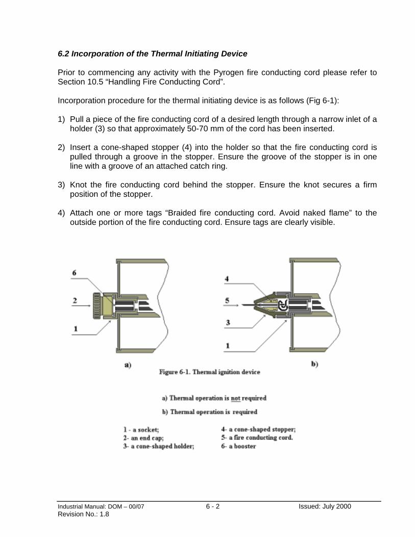
6.2 Incorporation of the Thermal Initiating Device
Prior to commencing any activity with the Pyrogen fire conducting cord please refer toSection 10.5 “Handling Fire Conducting Cord”.
Incorporation procedure for the thermal initiating device is as follows (Fig 6-1):
1) Pull a piece of the fire conducting cord of a desired length through a narrow inlet of aholder (3) so that approximately 50-70 mm of the cord has been inserted.
2) Insert a cone-shaped stopper (4) into the holder so that the fire conducting cord ispulled through a groove in the stopper. Ensure the groove of the stopper is in oneline with a groove of an attached catch ring.
3) Knot the fire conducting cord behind the stopper. Ensure the knot secures a firmposition of the stopper.
4) Attach one or more tags “Braided fire conducting cord. Avoid naked flame” to theoutside portion of the fire conducting cord. Ensure tags are clearly visible.

Industrial Manual: DOM – 00/07 6 - 3 Issued: July 2000Revision No.: 1.8
6.3 Spacing and Location
Once the size and number of Pyrogen MAG generators has been determined, theyshould be securely mounted on to a bulk head or similar location, observing thefollowing:
- Even distribution
Generators should be evenly distributed within the risk area, to achieve anunhindered distribution of the agent discharge.
- Orientation of aerosol discharge
Aerosol discharge should not be orientated across any route of exit.
Generators should be so oriented to reduce possible thermal damage caused by hotgenerators and extinguishant discharge. There should be no flammable or highlycombustible materials or equipment within a specified minimum clearance from thegenerator’s nozzle.
If there are any un-closable openings that cannot be avoided such as exits, doors andapertures, aerosol discharge should be directed across the likely fire zone and towardsthose openings, but not away from them.
- Clear obstructions
While Pyrogen aerosol is an extremely penetrating extinguishing agent, severeobstruction of the aerosol discharge pattern should be avoided. Several smallgenerators may be preferable to one large generator, should design limitations forsmaller units allow such a replacement. If it is not possible, the distance from the nozzleto the obstacle shall be not less than the minimum distance as specified below:
TABLE 6-1Minimum clearance
MAG-02 150 mmMAG-1 300 mmMAG-2 400 mmMAG-3 700 mmMAG-4 1000 mmMAG-5 700 mm
MAG-11...MAG-17 1500...2000 mm
In case of multiple obstacles the design factor shall be increased, such increase to bedetermined by preliminary tests conducted in the premises concerned.
Industrial Manual: DOM – 00/07 6 - 4 Issued: July 2000Revision No.: 1.8
- Environment
Temperature range of application for MAG generators is from -50 °C to + 65 °C.
Humidity range of application for MAG generators is up to 98 % humidity, non-condensing.
For installations where fire-conducting cord is used, the lowest temperature ofapplication has been limited to -15 °C.
Generators shall not be subjected to severe weather conditions or to mechanical,chemical or other damage. Where excessive climatic or mechanical exposures areexpected, suitable guards or enclosures shall be provided.
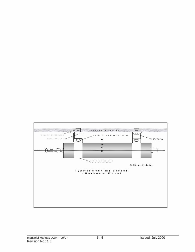
6.4 Mounting Methods
Pyrogen generators could be mounted in any orientation without affecting its aerosol-forming capability. It is important to bear in mind that the resultant aerosol being warmwould tend to rise at the onset. Pyrogen has been tested successfully, however, in thelateral mounting position on the ceiling i.e. under a most unfavourable orientation.Please refer to Diagram 6-2 and 6-3.
Diagram 6-2
Industrial Manual: DOM – 00/07 6 - 5 Issued: July 2000Revision No.: 1.8
T y p i c a l M o u n t i n g L a y o u t - H o r i z o n t a l M o u n t
S I D E V I E W
MA
G-
4
C O N C R E T E C E I L I N G
B R A C K E T ,2 X L S H A P E
B O L T , S T E E L , M 5
P Y R O G E N G E N E R A T O RM O U N T I N G B R A C K E T
W A L L P L U G , S T E E L , M 5 B O L T , N U T & W A S H E R , S T E E L , M 5

Industrial Manual: DOM – 00/07 6 - 6 Issued: July 2000Revision No.: 1.8
Diagram 6-3
Typical Mounting Layout - Within Ceiling Void, Vertical Mount
SIDE VIEWMAG-5
CONCRETE CEILING
CEILING VOID SIDE
RING COVER
PYROGEN GENERATORMOUNTING BRACKETS
STEEL ROD BSP THREADED, M8
NUT, M8
WALL PLUG, STEEL, M8
BRACKET, CEILING MOUNT3mm STEEL PLATE, COATED
STABILISING PLATE,3mm STEEL PLATE, COATED
FALSE CEILING
PROTECTED ENCLOSURE SIDE
Industrial Manual: DOM – 00/07 6 - 7 Issued: July 2000Revision No.: 1.8
6.5 Electric Wiring
Up to ten Pyrogen MAG generators may be connected on a single discharge circuit withone power source. Should more than ten generators be required for one enclosure, twocircuits with two separate power sources should be used.
Wiring between generators shall be by parallel configuration only.
- Cable
Cables should be fire-resistant. Conductors should be of copper, each having across-sectional area of not less than 1 mm2, or if stranded, not less than 0.5 mm2 shouldbe used.
The cable shall be screened and the care taken when the cable runs through a highfrequency energy zone, such as a two-way radio, a sonar, etc.
Should the cabling run alongside electric magnetic fields of high intensity, such as highvoltage transformers in power substations or cable tunnels, the cables shall be enclosedinto a steel conduit.
Cable screen and steel conduit shall be grounded in accordance with standardrequirements.
Should there be any possibility of the mechanical damage, the cables shall be enclosedinto a plastic or metal conduit.
- Power Sources
A standard power source that provides at least 2 Amp current and 6 to 24 Volts voltageshall be used.
The power source shall have a backup power supply of the same voltage. Where thebackup power is shared with other devices, sufficient capacity for a minimum of 24hour's standby condition, 1-hour alarm condition and thereafter, sufficient capacityremaining to discharge the generators shall be provided for.

Industrial Manual: DOM – 00/07 6 - 8 Issued: July 2000Revision No.: 1.8
- Wiring procedure
1) Install electrical wiring;
2) Install and connect such devices as audible and visual alarm devices, manual releasepoints or automatic activation fire panel, heat or flame detectors, timer, etc;
3) Connect miniature filament lamps with 12-24 Volts voltage and current up to 50mA inplace of MAG generators;
4) Ensure the manual release point or the automatic activation fire panel has beenprotected from the accidental discharge. Placing of a sign “Do not press. Device isunder service” is recommended.
5) Connect the circuit to a power supply;
6) Activate the system. All devices shall operate and all lamps shall glow. Should thesystem fail to operate properly, disconnect the power supply, check connectionsbetween devices, reconnect the power supply and try again.
7) Reset the system. All lamps shall be switched off;
WARNING! Prior to connecting MAG generators ensure the wires leading to thegenerators are not carrying voltage. Connection of MAG generators shouldalways be the last function in electrical wiring procedure.
8) Disconnect all of the lamps and connect the MAG generators in its place. Install MAGgenerators in accordance with installation recommendations;
9) Remove the sign on the manual release point or the automatic activation fire panel.

Industrial Manual: DOM – 00/07 6 - 9 Issued: July 2000Revision No.: 1.8
6.6 Connection of the Thermal Initiating Device
Should a thermal initiating device be incorporated into Pyrogen MAG generators (referto Section 6.2) complete the provision of automatic thermal operation by carrying out thefollowing steps:
Prior to connection of Pyrogen generators to the electrical circuit:
- Run the fire conducting cord through the most hazardous locations. Avoid closeproximity of the cord to the heat sources, such as exhaust pipes, hot surfaces etc.
- Clamp the fire conducting cord at appropriate points of its length to secure its fixedposition. Use plastic ties or any other appropriate means. Do not squeeze the cord.Avoid extreme tightening or sagging of the cord.
- Should several MAG generators be installed, knot extending fire conducting cordstogether so that all generators are connected to each other with the cord.
After connection of Pyrogen generators to the electrical circuit:
- Screw the holder (3, Fig. 6-1) with the fire conducting cord into a socket (1) of the MAGgenerator in place of a removed end cap (2).

Industrial Manual: DOM – 00/07 6 - 10 IssuedRevision No.: 1.8
2
1 43
From control panel
Rubber
Tightened with screws
Diagram 6 - 4 -- 2RMDT Connector Assembly and Wiring for Pyrogen Connectors
: July 2000
1
2 34
ToPyrogen
Soldered
Note: Only pins 1 & 2 areutilized for connection
Industrial Manual: DOM – 00/07 7 - 0 Issued: July 2000Revision No.: 1.8
AEROSOL FIRE SUPPRESSION SYSTEM
SECTION 7:
SYSTEM MARKINGS

Industrial Manual: DOM – 00/07 7 - 1 Issued: July 2000Revision No.: 1.8
SECTION 7. SYSTEM MARKINGS
7.1 Pyrogen Installation and Expiry Date Label
The following label is “filled in” and affixed to every generator used in the system by theinstallation contractor.
PYROGEN GENERATOR
INSTALLED DATE: ________________
EXPIRY DATE: ________________
For systems with electrical operation only (no thermal automatic operation) the installeddate is the current date and the expiry date is normally 10 years later, except wheninstalled in an aggressive environment where the service life is likely to be less, in whichcase please refer to an Approved Representative for an assessment of the expectedservice life.
For systems with thermal automatic operation (use of fire conducting cord) the installeddate is the current date and the expiry date is normally 5 years later.
After filling out these details the installer places the clear protective self-adhesive filmover the front of the label and attaches the label onto the generator adjacent to the bodylabel.
7.2 Pyrogen Warning & Instruction Signs
The following Warning and Instruction Signs shall be firmly attached to specifiedlocations by the installer on completion of Pyrogen installation in normally unoccupiedareas, where people may enter the enclosure for brief periods:
a) Label to be displayed at entrance to enclosure:
THIS AREA IS FITTED WITH A PYROGEN FIRE EXTINGUISHING AEROSOLSYSTEM
DO NOT ENTERUNLESS THE FIRE SUPRESSION SYSTEM IS ISOLATED
AFTER AEROSOL DISCHARGE DO NOT ENTERUNTIL AREA HAS BEEN THOROUGHLY VENTILATED

Industrial Manual: DOM – 00/07 7 - 2 Issued: July 2000Revision No.: 1.8
b) Label to be displayed inside enclosure
THIS AREA IS FITTED WITH A PYROGEN FIRE EXTINGUISHING AEROSOLSYSTEM
EVACUATE AREA ON SOUND OF ALARM
AFTER AEROSOL DISCHARGE DO NOT ENTERUNTIL AREA HAS BEEN THOROUGHLY VENTILATED
c) Label to be displayed at System Isolate Switch
PYROGEN SYSTEM ISOLATE SWITCH
WARNINGCHECK THAT THE AREA IS CLEAR OF PERSONNEL BEFORE RE-
ACTIVATING THE SYSTEM
d) Label to be displayed at Manual Release Point
PYROGEN FIRE EXTINGUISHING AEROSOL SYSTEM
MANUAL RELEASE POINT
ENSURE AREA IS EVACUATED BEFORE RELEASE OF PYROGENAEROSOL
e) Tag to be attached to the Fire Conducting Cord
BRAIDED FIRE CONDUCTING CORDAVOID NAKED FLAME
Industrial Manual: DOM – 00/07 8 - 0 Issued: July 2000Revision No.: 1.8
AEROSOL FIRE SUPPRESSION SYSTEM
SECTION 8:
SYSTEM COMMISSIONING

Industrial Manual: DOM – 00/07 8 - 1 Issued: July 2000Revision No.: 1.8
SECTION 8. SYSTEM COMMISSIONING
A Pyrogen Warranty Card is required to be completed by a contractor upon Pyrogeninstallation and sent to your Pyrogen Key Representative/Distributor.
The completed Pyrogen installation shall be commissioned in accordance withCommissioning Checklist attached in Appendix A (Form 2).
On completion and acceptance of the commissioning procedure, the installationcontractor shall issue a Notice of Completion in Appendix A (Form 3).
Commissioning should be carried out by trained and authorised personnel only.
Industrial Manual: DOM – 00/07 9 - 0 Issued: July 2000Revision No.: 1.8
AEROSOL FIRE SUPPRESSION SYSTEM
SECTION 9:
SYSTEM MAINTENANCE
Industrial Manual: DOM – 00/07 9 - 1 Issued: July 2000Revision No.: 1.8
SECTION 9. SYSTEM MAINTENANCE
The user of the installation should ensure that the system is in good workingorder at all times. The user should carry out monthly inspections of the firesuppression equipment. This should include looking out for obstruction of the dischargenozzle, extension/alteration of the protected enclosure, openings left unclosed that werenot catered for during design, and that the position and orientation of the Pyrogengenerators remain in the designed position.
The installation should be inspected at least twice a year by an authorisedinspector. The inspection plan should include all components of the system and partsof the premises necessary for the effective operation of the system.
A system maintenance log should be kept and status of every maintenance visit isrecorded. For a typical system maintenance report refer to the attached MaintenanceChecklist in Appendix A (Form 4).
Periodic check-up is required for electrical circuitry of Pyrogen system. Thefollowing steps shall be undertaken:
If the control system is designed to transmit alarm signals to a remote manned centre,always ensure that the link is disabled, or in the event that disabling the link is not anoption, it would be essential to notify the centre before undertaking the test. Occupant ofthe premises should also be notified that the system test might result in the soundersbeing activated.
WARNING! Prior to the start of ANY maintenance work, always ensure as the firststep, that wiring to all Pyrogen generators have been electrically isolated. Shouldthermal automatic operation be used unscrew holders with the fire conductingcord from all Pyrogen generators and replace them with attached end caps.Failure to do so may result in unwanted spurious discharge.
1) Disconnect the wiring at EVERY single MAG generator. This is extremelyimportant to ensure that there are no generators inadvertently left connected.
2) Connect miniature filament lamps with 12-24 Volts voltage and current up to 50 mAin place of MAG generators.
3) Connect the circuit to a power supply.
4) Activate the system. All devices shall operate and all lamps shall glow. Should thesystem fail to operate properly, disconnect the power supply, check connectionsbetween devices, reconnect the power supply and try again.
5) Reset the system. All lamps shall be switched off.
Industrial Manual: DOM – 00/07 9 - 2 Issued: July 2000Revision No.: 1.8
WARNING! Prior to connecting MAG generators, ensure the wires leading to thegenerators are not carrying voltage. Connection of MAG generators shouldalways be the last function in electrical wiring procedure.
6) Disconnect all of the lamps and connect the MAG generators in its place. InstallMAG generators in accordance with installation recommendations.
7) Screw holders with the fire conducting cord into a socket of MAG generator in placeof the removed end caps.
8) Remove the sign on the manual release point or the automatic activation fire panel.
For installations where the fire conducting cord is used, a regular check on itsmechanical integrity is recommended. The following steps shall be undertaken priorto step 7 of the above check-up procedure for electrical circuitry:
1) Ensure the fire conducting cord is protected by braiding.
2) Ensure the fire conducting cord is intact. There shall be no cracks or fractures of thecord. The cord shall have uniform thickness all along its length.
3) Ensure all grommets/bushes securing the position of the cord are in place.
4) Ensure that at least one warning/instruction tag is attached to the fire conductingcord and clearly visible.

Industrial Manual: DOM – 00/07 10 - 0 Issued: July 2000Revision No.: 1.8
AEROSOL FIRE SUPPRESSION SYSTEM
SECTION 10:
SAFETY MEASURES

Industrial Manual: DOM – 00/07 10 - 1 Issued: July 2000Revision No.: 1.8
SECTION 10. SAFETY MEASURES
10.1 Personnel safety
The uses of Pyrogen automatic total flooding systems are limited to unoccupied andnormally unoccupied areas only. In any proposed use of Pyrogen where there is apossibility that people may enter the protected enclosure or be close to the protectedrisk, the following safety aspects shall apply:
- a thermal automatic operation shall not be used;
- a system isolate switch at the entrance to the protected area, to prevent actuationduring abnormal periods of occupation, such as maintenance and repair.
- a location drawing at any manual actuation points.
- exit routes kept clear at all times, emergency lighting and adequate direction signs tominimise travel distances.
- consideration should be given to canister location in the event of spurious activation.Unless absolutely unavoidable, canisters should not be placed at head height or inclose proximity to egress doors nor emergency exits.
- outward-swinging doors shall be self-latching and incorporate a self-closingmechanism to prevent possibility of doors opening inadvertently due toincrease of pressure within the protected enclosure during discharge. Doorsshould be able to be opened from the inside including when locked from the outside.
- continuous visual and audible alarms at entrances and designated exits, until theprotected area has been made safe.
- warning and instruction signs in accordance with Section 7.2.
- pre-discharge alarms operated immediately upon detection of the fire.
- a time delay incorporated within the manual release point and commencing uponPyrogen system operation.
- means for ventilation after discharge; forced draft ventilation will often be necessary.Care should be taken to completely dissipate hazardous atmospheres and not just tobe moved to other locations.
Industrial Manual: DOM – 00/07 10 - 2 Issued: July 2000Revision No.: 1.8
- written instructions appropriate to the risk, instructions and drills of all personnelwithin or in the vicinity of protected area, including maintenance or constructionpersonnel who may be brought into the area, to ensure their correct actions whenthe system operates.
- A hold off switch should be provided within any protected area if there is a risk ofpersonnel taking longer to egress than any pre-discharge alarm may allow. This mayapply to persons who are physically or mentally impaired, involved in maintenance orare unfamiliar or untrained in the company fire procedures.
10.2 Potential hazards
The discharge of Pyrogen in fire extinguishing concentrations represents potentialhazards to personnel in protected area. The hazards include the following:
- high obscuration caused by the aerosol during and after discharge.
- potential toxicity due to some by-products of the aerosol-generatingcombustion reaction .
- thermal hazard due to a high temperature at the end plate nozzle . See Section2.9 Design Limitations for minimum clearances.
Please refer to Section 1.8 for a detailed information on the above hazards.
10.3 Re-entry
Following the use of Pyrogen, personnel should not enter the protected area until it hasbeen thoroughly ventilated. The minimum holding times should be observed prior toventilation of the protected area (please refer to Section 2.10 for minimum holdingtimes). Unless stated otherwise the minimum holding time permitted before re-entry is 3minutes.
Avoid exposure to the fire by-products and extinguishant mixture.
The wearing of suitable RPE & other available means of protection may be requiredshould it be necessary to enter the area before it is fully ventilated.
Industrial Manual: DOM – 00/07 10 - 3 Issued: July 2000Revision No.: 1.8
10.4 Clean- up
Following a system discharge the aerosol particles that have settled should bevacuumed, using HEPA filter fitted equipment, brushed or, if appropriate, washed away.
Protective gloves and goggles should be worn. A suitable RPE or mask may berequired.
Be aware, that any residue that is allowed to build up in large quantities and toabsorb moisture may become electrically conductive.
When replacing MAG generators, be aware that immediately after discharge thecanisters outer surface may exceed 200°°°°C. Therefore, protective gloves should beworn before handling generators until at least 15 minutes after discharge.
10.5 Handling Fire Conducting Cord
The following safety measures shall apply during installation, maintenance and anyother activity involving Pyrogen fire conducting cord:
- Do not smoke or use any heat source with a surface temperature exceeding 100°C.
- Avoid accumulation of static electricity. Cotton work clothing is recommended. Priorto any operation with fire conducting cord relieve any possible charge of staticelectricity by touching an earth point or an earthed metal object.
- Avoid rough handling of the fire conducting cord.
Fire conducting cord may be used in unoccupied areas only.
10.6 Hot Work
As naked flame or prolonged exposure to temperatures above 400°C may causeactivation of the generators, hot work must not be carried out within the vicinity ofany generator. If so they shall be removed prior to any hot work being carried out.
10.7 Storage and Transportation
Storage and transportation shall be in accordance with Class 4.1 Dangerous GoodsClassification.
Industrial Manual: DOM – 00/07 A - 0 Issued: July 2000Revision No.: 1.8
AEROSOL FIRE SUPPRESSION SYSTEM
APPENDIX A:
APPROVAL DOCUMENTATION
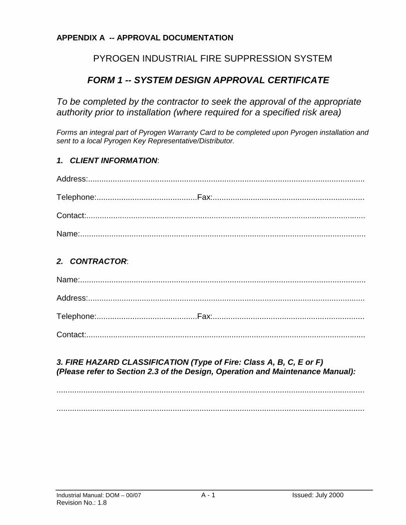
Industrial Manual: DOM – 00/07 A - 1 Issued: July 2000Revision No.: 1.8
APPENDIX A -- APPROVAL DOCUMENTATION
PYROGEN INDUSTRIAL FIRE SUPPRESSION SYSTEM
FORM 1 -- SYSTEM DESIGN APPROVAL CERTIFICATE
To be completed by the contractor to seek the approval of the appropriateauthority prior to installation (where required for a specified risk area)
Forms an integral part of Pyrogen Warranty Card to be completed upon Pyrogen installation andsent to a local Pyrogen Key Representative/Distributor.
1. CLIENT INFORMATION:
Address:............................................................................................................................
Telephone:.............................................Fax:....................................................................
Contact:.............................................................................................................................
Name:................................................................................................................................
2. CONTRACTOR:
Name:................................................................................................................................
Address:............................................................................................................................
Telephone:.............................................Fax:....................................................................
Contact:.............................................................................................................................
3. FIRE HAZARD CLASSIFICATION (Type of Fire: Class A, B, C, E or F)(Please refer to Section 2.3 of the Design, Operation and Maintenance Manual):
..........................................................................................................................................
..........................................................................................................................................

Industrial Manual: DOM – 00/07 A - 2 Issued: July 2000Revision No.: 1.8
4. PROTECTED SPACE IDENTIFICATION:
Name ofSpace......................................................................................................................
Occupancy: unoccupied................................. normally unoccupied................. intermittently occupied..............
5. ELECTRIC POWER SUPPLY AVAILABLE:
Main..................................................................................................................................
Emergency........................................................................................................................
6. NUMBER AND ELECTRICAL CHARACTERISTICS OF EQUIPMENT TO BESHUTDOWN
.....................................................................................................................
7. DESIGN CALCULATIONS:
Protected space dimensions:
Height...................................................................................................................m
Length...................................................................................................................m
Width....................................................................................................................m
Area......................................................................................................................m2
Total area of unclosable openings to the total area of the enclosure......................%
Protected space volume:Maximum Gross volume......................................................................................................m3
Add for exhaust and inlet ducts..................................................... m3
Deduct non-removable equipment, e.g. tanks, etc..........................m3
Design Net volume...................................................................... .m3

Industrial Manual: DOM – 00/07 A - 3 Issued: July 2000Revision No.: 1.8
Quantity of agent required:
Design Factor: (Typ.100 g/m3) ………………………….......................……
Minimum Design Quantity: Minimum Design Factor x Design Net vol.......................g
Actual Design Quantity (should compensate for aerosol losses via unclosable openings,due to forced ventilation and other special conditions be required) ….....g
Pyrogen generators selected: Type Quantity
MAG- ............. MAG- ............. MAG- ............. MAG- ............. MAG- .............,
Installed quantity of agent as determined by sizes of Pyrogen generatorsavailable:...............g
This quantity shall never be less than the minimum design quantity.
This form must be completed by the contractor to seek the approval of the appropriate authority,which may require that approved installers are to submit details to the authority beforeinstallation.
This form shall form part of the Pyrogen Warranty Card to be completed by the contractor uponPyrogen installation and sent to a local Pyrogen Key Representative/Distributor.
8. METHOD OF ACTUATION
a) Automatic Electrical ………………………………………………………………(i.e. Control Panel & detection system required – please provide for further data)
Automatic Thermal (Pyrotechnic Fuse)……………………………………………..(Typically Engine, Marine & Machinery Applications)
Automatic Electrical/Thermal ………………………………
b) Manual Electrical ………………………………………….(Typically Engine, Marine & Machinery Applications)

Industrial Manual: DOM – 00/07 A - 4 Issued: July 2000Revision No.: 1.8
PYROGEN INDUSTRIAL FIRE PROTECTION SYSTEM
FORM 2 -- COMMISSIONING AND ACCEPTANCE TESTING
Criteria for Acceptance
The completed Pyrogen system shall be commissioned in accordance with thisCommissioning Checklist. On completion and acceptance of the commissioning, theinstallation contractor shall issue a commissioning report.
COMMISSIONING CHECK LIST
No Inspection Complianceverified
Remarks
1 Obtain a copy of the System Designapproval Certificate ( Form 1)
2 Isolate Pyrogen generators bydisconnecting generators power supplyor system power supply. Should thermalautomatic operation be used, unscrewholders with fire conducting cord andreplace them with attached end caps
3 Risk area classification(a) Is it the same as the System Design
Approval Certificate (Item 3 Form 1)(b) Is the occupation the same as the System
Design Approval Certificate (Item 4 Form 1)
(c) Are air handling shutdown relays and firedampers provided
(e) Are there any uncloseable openings
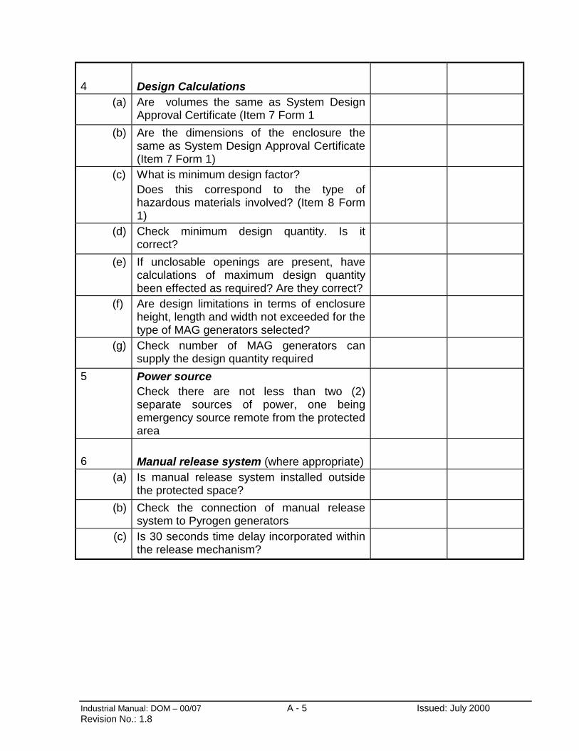
Industrial Manual: DOM – 00/07 A - 5 Issued: July 2000Revision No.: 1.8
4 Design Calculations (a) Are volumes the same as System Design
Approval Certificate (Item 7 Form 1
(b) Are the dimensions of the enclosure thesame as System Design Approval Certificate(Item 7 Form 1)
(c) What is minimum design factor?Does this correspond to the type ofhazardous materials involved? (Item 8 Form1)
(d) Check minimum design quantity. Is itcorrect?
(e) If unclosable openings are present, havecalculations of maximum design quantitybeen effected as required? Are they correct?
(f) Are design limitations in terms of enclosureheight, length and width not exceeded for thetype of MAG generators selected?
(g) Check number of MAG generators cansupply the design quantity required
5 Power sourceCheck there are not less than two (2)separate sources of power, one beingemergency source remote from the protectedarea
6 Manual release system (where appropriate)(a) Is manual release system installed outside
the protected space?
(b) Check the connection of manual releasesystem to Pyrogen generators
(c) Is 30 seconds time delay incorporated withinthe release mechanism?
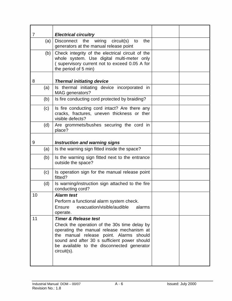
Industrial Manual: DOM – 00/07 A - 6 Issued: July 2000Revision No.: 1.8
7 Electrical circuitry(a) Disconnect the wiring circuit(s) to the
generators at the manual release point
(b) Check integrity of the electrical circuit of thewhole system. Use digital multi-meter only( supervisory current not to exceed 0.05 A forthe period of 5 min)
8 Thermal initiating device (a) Is thermal initiating device incorporated in
MAG generators? (b) Is fire conducting cord protected by braiding?
(c) Is fire conducting cord intact? Are there anycracks, fractures, uneven thickness or thervisible defects?
(d) Are grommets/bushes securing the cord inplace?
9 Instruction and warning signs (a) Is the warning sign fitted inside the space?
(b) Is the warning sign fitted next to the entranceoutside the space?
(c) Is operation sign for the manual release pointfitted?
(d) Is warning/instruction sign attached to the fireconducting cord?
10 Alarm testPerform a functional alarm system check.Ensure evacuation/visible/audible alarmsoperate.
11 Timer & Release testCheck the operation of the 30s time delay byoperating the manual release mechanism atthe manual release point. Alarms shouldsound and after 30 s sufficient power shouldbe available to the disconnected generatorcircuit(s).
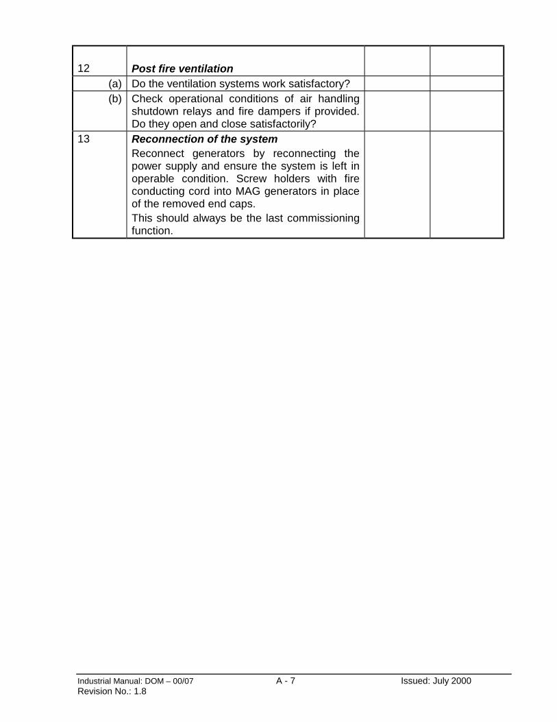
Industrial Manual: DOM – 00/07 A - 7 Issued: July 2000Revision No.: 1.8
12 Post fire ventilation(a) Do the ventilation systems work satisfactory?(b) Check operational conditions of air handling
shutdown relays and fire dampers if provided.Do they open and close satisfactorily?
13 Reconnection of the systemReconnect generators by reconnecting thepower supply and ensure the system is left inoperable condition. Screw holders with fireconducting cord into MAG generators in placeof the removed end caps.This should always be the last commissioningfunction.
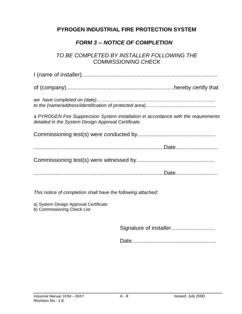
Industrial Manual: DOM – 00/07 A - 8 Issued: July 2000Revision No.: 1.8
PYROGEN INDUSTRIAL FIRE PROTECTION SYSTEM
FORM 3 -- NOTICE OF COMPLETION
TO BE COMPLETED BY INSTALLER FOLLOWING THECOMMISSIONING CHECK
I (name of installer).......................................................................................
of (company).....................................................................hereby certify that
we have completed on (date)…………………………………………………………….......to the (name/address/identification of protected area)………..........................................
a PYROGEN Fire Suppression System installation in accordance with the requirementsdetailed in the System Design Approval Certificate.
Commissioning test(s) were conducted by..................................................
...................................................................................Date...........................
Commissioning test(s) were witnessed by..................................................
...................................................................................Date...........................
This notice of completion shall have the following attached:
a) System Design Approval Certificateb) Commissioning Check List
Signature of installer............................
Date......................................................

Industrial Manual: DOM – 00/07 A - 9 Issued: July 2000Revision No.: 1.8
PYROGEN INDUSTRIAL FIRE PROTECTION SYSTEM
FORM 4 -- MAINTENANCE CHECK LIST
Maintenance Organisation................................................................................................
Premises..........................................................................................................................
Address...........................................................................................................................
No ITEM MONTHLY,BY OWNER
ANNUALLY,BY AUTHORISEDINSPECTOR
1 Electrically isolate Pyrogen generators. Unscrewholders with fire conducting cord from MAGgenerators and replace them with attached end caps.
√ √
2 Confirm the generators are secure, undamaged andfree from corrosion
√ √
3 Check that generators’ nozzles are unobstructedwithin the specified in Sec. 2.9 minimum clearances
√ √
4 Confirm all electrical wiring and connections are intact √ √5 Confirm fire conducting cord is braided and intact √ √6 Open the manual release point enclosure √ √7 Confirm that 30 sec time delay, evacuation and/or
audible, visual and fire alarms operate√ √
8 Check that instruction and warning signs are legible √ √9 Inspect power source condition √ √10 Inspect emergency power source (back-up battery)
condition√ √
11 Confirm that all previously requested rectification’s ormodifications have been completed
√ √
12 Inspect the area to confirm there are no unclosableopenings
- √
13 Inspect controls for closing area vents whereapplicable. Inspect for damage, corrosion,accessibility and test correct operation.
- √
14 Check the post fire ventilation facilities are functional. - √15 Check that the expiry date of all generators will not
occur within the next 12 months and report to theowner.
- √
16 Check the generator’s electric activation circuit. Followsteps 1-8 of Section 9.
- √
17 Check that all system controls are returned to normaland system is “on line”
- √
18 Reconnect Pyrogen generators. Screw holders withfire conducting cord into the generators.
- √
19 Record all inspections and necessary rectification’s - √20 Inform owner - √
Signed:............................................ Date:........................................
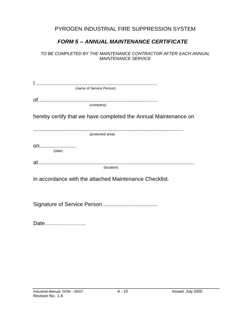
Industrial Manual: DOM – 00/07 A - 10 Issued: July 2000Revision No.: 1.8
PYROGEN INDUSTRIAL FIRE SUPPRESSION SYSTEM
FORM 5 -- ANNUAL MAINTENANCE CERTIFICATE
TO BE COMPLETED BY THE MAINTENANCE CONTRACTOR AFTER EACH ANNUALMAINTENANCE SERVICE
I ..............................................................................(name of Service Person)
of.....................................................................…….(company)
hereby certify that we have completed the Annual Maintenance on
.................................................................................................(protected area)
on........................ (date)
at.....................................................................................................(location)
in accordance with the attached Maintenance Checklist.
Signature of Service Person....................................
Date.............…………....
Related Documents