2 The Open Thermodynamics Journal, 2010, 4, 2-12 1874-396X/10 2010 Bentham Open Open Access Pulverised-Coal Combustion with Staged Air Introduction: CFD Analysis with Different Thermal Radiation Methods Risto V. Filkoski * University “Sts Cyril and Methodius”, Faculty of Mechanical Engineering Karpo II, P.O.Box 464, Skopje, Republic of Macedonia Abstract: Combustion chamber designers endeavour to achieve optimum operating conditions that give maximum com- bustion efficiency, together with minimum pollutant formation rate. Modelling of fossil fuel utility boilers has reached a remarkable development in recent years. Particularly, the application of computational fluid dynamics (CFD) modelling technology and other advanced mathematical methods offer opportunities for analysis, optimisation and options examina- tion in order to increase the overall efficiency of the energy facilities. The main purpose of the present study was to inves- tigate how the results obtained with two radiative heat transfer methods, the P1 approximation method and the discrete ordinates (DO) method, fit temperature field in a boiler furnace on pulverised coal, with implemented over-fire air (OFA) ports. The overall framework of the CFD modelling approach is described. The numerical modelling results for boiler baseline operating conditions are compared with a test matrix of local temperature measurements. An accuracy analysis of the P1 and DO methods is done on a basis of a comparison between the numerically obtained and measured temperature profiles. Keywords: Coal combustion, heat transfer, thermal radiation, CFD techique, modelling. INTRODUCTION Well-grounded technical solutions of boiler furnaces and combustion chambers are aimed to achieve operating condi- tions that give optimal heat transfer, maximum combustion efficiency and minimum pollutant formation rate. This leads to increasing the overall efficiency of the energy facilities and is particularly important in the cases when coal is used as fuel. Despite the calls for larger utilisation of gas and re- newable energy sources, the role of coal is crucial and, probably, its importance as energy resource is not going to be endangered significantly in the coming decade or two. There is a certain re-emergence of coal as a primary fuel for power generation, as a result of technological changes that have reduced the amount of pollutants and particulate emis- sions to the atmosphere, and recent international worries about security of gas supply. At the same time, the interest on performance optimisa-tion of utility boilers has become very relevant, aiming at extending their lifetime, increasing the overall efficiency and reducing the emissions of pollut- ants, which is quite clear with the rising costs and increasing demand for energy. In many combustion devices, including boiler furnaces, the radiant heat transfer is the dominant mode of energy transfer. In order to predict accurately the temperature field, which is in direct correlation with the combustion efficiency and NO x formation, it is important to utilise proper radiative heat transfer model. As a part of the efforts to establish *Address correspondence to this author at the University “Sts Cyril and Methodius”, Faculty of Mechanical Engineering Karpo II, P.O.Box 464, Skopje, Republic of Macedonia; Tel: +389 2 3099 224; Fax: +389 2 3099 298; E-mail: [email protected]; [email protected] appropriate modelling and simulation approach for certain conditions, the main objective of the present study was to investigate how some established thermal radiation methods describe the temperature field in a furnace of utility boiler on pulverised coal with staged air/fuel introduction. MODELLING AND SIMULATION TECHNIQUES FOR FURNACE APPLICATIONS The mathematical modelling and numerical simulation have already been widely accepted as low-cost, efficient engineering tools for analysis and optimisation of combus- tion systems [1]. These tools considerably facilitate the in- vestigation of the influence of various process and design parameters, such as fuel proximate and ultimate analysis, particle size distribution, air and fuel inlet distribution, over- all furnace geometry (furnace shape, air and fuel inlets, lay- out of air staging nozzles, recirculation holes), burners’ de- sign, flame-wall interaction phenomena, heat transfer degra- dation, slagging propensity etc. to the heat transfer condi- tions, overall combustion efficiency, plant efficiency and the emission of pollutants. Advanced combustion models and computational fluid dynamics (CFD) techniques are exten- sively used to accurately solve the aerodynamics equations involved in the problem, and to predict coal burnout and heat transfer in large utility boilers. Compared to a purely ex- perimental study, CFD modelling approach offers significant benefits: cost and time reduction, reproducibility of bound- ary conditions, as well as detailed insight into the complex interacting physical phenomena determining the combustion process. A comprehensive historical review of the modelling approaches and techniques of pulverised coal boilers is given in [2], pointing out very different standpoints and objectives.

Welcome message from author
This document is posted to help you gain knowledge. Please leave a comment to let me know what you think about it! Share it to your friends and learn new things together.
Transcript

2 The Open Thermodynamics Journal, 2010, 4, 2-12
1874-396X/10 2010 Bentham Open
Open Access
Pulverised-Coal Combustion with Staged Air Introduction: CFD Analysis with Different Thermal Radiation Methods
Risto V. Filkoski*
University “Sts Cyril and Methodius”, Faculty of Mechanical Engineering Karpo II, P.O.Box 464, Skopje, Republic of
Macedonia
Abstract: Combustion chamber designers endeavour to achieve optimum operating conditions that give maximum com-
bustion efficiency, together with minimum pollutant formation rate. Modelling of fossil fuel utility boilers has reached a
remarkable development in recent years. Particularly, the application of computational fluid dynamics (CFD) modelling
technology and other advanced mathematical methods offer opportunities for analysis, optimisation and options examina-
tion in order to increase the overall efficiency of the energy facilities. The main purpose of the present study was to inves-
tigate how the results obtained with two radiative heat transfer methods, the P1 approximation method and the discrete
ordinates (DO) method, fit temperature field in a boiler furnace on pulverised coal, with implemented over-fire air (OFA)
ports. The overall framework of the CFD modelling approach is described. The numerical modelling results for boiler
baseline operating conditions are compared with a test matrix of local temperature measurements. An accuracy analysis of
the P1 and DO methods is done on a basis of a comparison between the numerically obtained and measured temperature
profiles.
Keywords: Coal combustion, heat transfer, thermal radiation, CFD techique, modelling.
INTRODUCTION
Well-grounded technical solutions of boiler furnaces and
combustion chambers are aimed to achieve operating condi-
tions that give optimal heat transfer, maximum combustion
efficiency and minimum pollutant formation rate. This leads
to increasing the overall efficiency of the energy facilities
and is particularly important in the cases when coal is used
as fuel. Despite the calls for larger utilisation of gas and re-
newable energy sources, the role of coal is crucial and,
probably, its importance as energy resource is not going to
be endangered significantly in the coming decade or two.
There is a certain re-emergence of coal as a primary fuel for
power generation, as a result of technological changes that
have reduced the amount of pollutants and particulate emis-
sions to the atmosphere, and recent international worries
about security of gas supply. At the same time, the interest
on performance optimisa-tion of utility boilers has become
very relevant, aiming at extending their lifetime, increasing
the overall efficiency and reducing the emissions of pollut-
ants, which is quite clear with the rising costs and increasing
demand for energy.
In many combustion devices, including boiler furnaces, the radiant heat transfer is the dominant mode of energy transfer. In order to predict accurately the temperature field, which is in direct correlation with the combustion efficiency and NOx formation, it is important to utilise proper radiative heat transfer model. As a part of the efforts to establish
*Address correspondence to this author at the University “Sts Cyril and
Methodius”, Faculty of Mechanical Engineering Karpo II, P.O.Box 464,
Skopje, Republic of Macedonia; Tel: +389 2 3099 224; Fax: +389 2 3099
298; E-mail: [email protected]; [email protected]
appropriate modelling and simulation approach for certain conditions, the main objective of the present study was to investigate how some established thermal radiation methods describe the temperature field in a furnace of utility boiler on pulverised coal with staged air/fuel introduction.
MODELLING AND SIMULATION TECHNIQUES FOR FURNACE APPLICATIONS
The mathematical modelling and numerical simulation have already been widely accepted as low-cost, efficient engineering tools for analysis and optimisation of combus-tion systems [1]. These tools considerably facilitate the in-vestigation of the influence of various process and design parameters, such as fuel proximate and ultimate analysis, particle size distribution, air and fuel inlet distribution, over-all furnace geometry (furnace shape, air and fuel inlets, lay-out of air staging nozzles, recirculation holes), burners’ de-sign, flame-wall interaction phenomena, heat transfer degra-dation, slagging propensity etc. to the heat transfer condi-tions, overall combustion efficiency, plant efficiency and the emission of pollutants. Advanced combustion models and computational fluid dynamics (CFD) techniques are exten-sively used to accurately solve the aerodynamics equations involved in the problem, and to predict coal burnout and heat transfer in large utility boilers. Compared to a purely ex-perimental study, CFD modelling approach offers significant benefits: cost and time reduction, reproducibility of bound-ary conditions, as well as detailed insight into the complex interacting physical phenomena determining the combustion process.
A comprehensive historical review of the modelling approaches and techniques of pulverised coal boilers is given in [2], pointing out very different standpoints and objectives.

Pulverised-Coal Combustion with Staged Air Introduction The Open Thermodynamics Journal, 2010, Volume 4 3
The traditional approach of boiler manufacturers, that is essentially identical to the usual design practices of boilers and furnaces of very different nature, is based on the use of relatively simple semi-empirical models, developed in pilot plants or inferred from the practical experience.
Since the early 70s, more elaborated models for predict-
ing heat transfer in furnaces started to appear. A typical en-gineering calculation method is elaborated in [3]. In the same work, a plug-flow method is described, aimed for simple furnace calculations, and known as zone method. The
method is based on division of the domain into a few amount of volume cells and it has been widely used by researchers and engineers (for instance [4, 5]). This was some kind of a predecessor of the application of the popular Hottel zone
method for radiative heat transfer, already available in litera-ture [6], but still not applied in the design of utility boilers, since it requires previously defined reliable velocity field and heat release (combustion) patterns. The former Soviet ap-
proach to the furnace modelling is also expressed through the works of several other authors [7, 8].
The adoption of the various forms of zone methods coin-cided and, in some extent, was one of the preconditions for
development of CFD techniques, with all their advantages and shortcomings. Nowadays researchers’ efforts are con-centrated in two general directions: (1) to improve the fun-damental models of the complex phenomena that occur in
the combustion systems and (2) to adopt some simplifica-tions in order to make possible the extrapolation of research results to industrial applications.
The permanent progress in computers capability over the
last two decades has enabled development and application of massive mathematical models of turbulent flows, heat trans-fer and combustion in the furnaces and extensive use of CFD techniques, with quite satisfactory results [9-14]. Three-
dimensional comprehensive models of industrial-scale fur-naces have been developed and successfully applied for years now [9-20, 22]. There are also combinations of origi-nal models of separate processes and existing computational
codes [23, 24]. Of course, there is still an area for further improvements, having as a subject a detailed mathematical description of physical and chemical processes in certain specific conditions. Numerical codes describing the proc-
esses in coal-fired boilers, based on solution of differential conservation equations, have been a subject of many investi-gations [10, 15-20, 22]. While some consider numerical as-pects [17] or aerodynamics [22] in small-scale furnace iso-
thermal models, others present comprehensive combustion models of large-scale furnaces. The majority of the models use variations of the SIMPLE algorithm for coupling the continuity and momentum equations. Despite some weak-
nesses, the k- turbulen-ce model, or some derivatives, like RNG k- model [10], or k- -kp two-phase turbulence model [19], are often used in combustion systems. Gas phase con-ser-vation equations are mostly time-averaged, but some
prefer the Favre-averaged equations instead [16].
Two-phase flow is usually described by Eulerian-Lagrangian approach and PSI-Cell method for taking into account the influences between phases, with some excep-
tions using Eulerian-Eulerian approach, or two-fluid trajec-tory model [19].
Most of the combustion sub-models given in [10, 15, 16, 18-20, 22] separately treat particle devolatilisation, char oxida tion and additional gas phase reactions. One of the most important segments of the furnace modelling is the way of radiative heat transfer incorporation. Thermal radiation in the furnaces can be modelled by means of various ap-proaches, like discrete transfer method [15], discrete ordi-nates method [16, 19-21], six-fluxes method [18], Monte Carlo method [10], or so called P-N approximation method [25], including its P-1 variant, as it is used in [26, 27]. In general, it should be pointed out that a comprehensive model of the furnace processes must balance sub-models sophisti-cation with computational practicality.
DESCRIPTION OF THE CASE STUDY: BOILER
AND FUEL MAIN PROPERTIES AND FURNACE GEOMETRY
The modelling technique described in this paper has been validated against data acquired from the corner-fired pulver-ised coal boiler at a power plant with gross output of 160 MWe [28]. A top view (cross-section), showing the boiler dimensions and inlet air trajectories, is presented in Fig. (1) [28]. The boiler furnace is rectangular in shape, 11.58 m long and 8.53 m wide. The inlet air and coal are fed from the furnace corners, at 42
o and 31
o, as shown, to create a fireball
swirling (counterclockwise, as viewed from the top). The boiler is retrofitted with low-NOx burners, concentric firing system (CFS) ports, close-coupled overfire air (CCOFA) and separate overfire air (SOFA) ports. The boiler was modified with fifteen 152 mm diameter circular ports at various levels, which can accommodate appropriate water-cooled probes for temperature measurement. The port locations are selected taking into account the importance of data from various loca-tions. A schematic diagram of the boiler furnace represented in Fig. (1), also indicates the location of various fuel, air and measurement ports.
The coal properties for the test case and the boiler main operating conditions are listed in Tables 1 and 2 [28]. The secondary air flow includes air through CFS, CCOFA and SOFA ports. A schematic representation of the ports: top SOFA, mid SOFA, bottom SOFA, top CCOFA, bottom CCOFA, coal burners No. 1-4, CFS ports and auxiliary oil ports, is given in Fig. (1) [28].
Some details of the burners’ configuration, including the height of each port with respect to the datum, which is at the bottom of the ash hopper, and the port area, are shown in Table 3 [28]. For the modelling purposes, it was assumed that the air was evenly distributed between all inlet ports in proportion to the areas reported in Table 3 and that those areas were adjusted for the test according to the percentage opening. The inlet air was heated to 260
oC and the ratio of
primary air to as-received coal mass flow rate was 1.7.
The simulations have been performed on a basis of the Fluent CFD code, version 6.1, adapted for pulverised coal industrial and utility scale boiler furnaces. Geometry outline of the calculation domain and the numerical mesh are pre-sented in Fig. (2). Special attention has been paid to the grid design, in order to reduce numerical error as much as possi-ble. The fact that the smallest lengths in combusting turbu-lent fluid flows are in the much smaller magnitude order, compared to the huge dimensions of utility boiler furnaces,
4 The Open Thermodynamics Journal, 2010, Volume 4 Risto V. Filkoski
make it necessary either to discretise the solution domain using control volumes with dimensions of the order of some milimeters in all directions, either to find some other solu-tion. Considering the time available and the computer re-sources, the first option is not feasible.
Table 1. Coal Properties (as Received) [28]
Proximate Analysis Value
Total moisture, wt % 4.1
Volatile matter, wt % 28.3
Fixed carbon, wt % 55.7
Ash, wt % 12.0
Mean particle diameter, μm 27
Coal heating value, kJ/kg 31040
As a compromise, much denser mesh is utilised in re-gions where large gradients of variables can be expected, such as the near-burner-regions. In this case, there are totally 688,886 tetrahedral hybrid cell elements in the domain. According to the previous experiences with simulations of
other boiler furnaces with comparable domain dimensions and complexity, the grid is fine enough to give grid-independent solutions, showing satisfactory convergence and accuracy and, at the same time, to meet the restrictions in computational time [26, 27, 29].
Table 2. Boiler Operating Conditions [28]
Parameter, Unit Value
Gross load, MWe 156
Coal feed, kg/h 50,200
Primary air flow rate, kg/h 85,340
Air temperature, oC 260
Secondary air, kg/h 546,000
Burner tilt, deg. -5
Thermocouple pyrometry, as a practical and reliable method of measuring gas temperature in full-scale boilers, is used in this case. The procedure for temperature measure-ments is described in details in [28]. Gas temperature measurements are obtained with a type S, Pt/Pt-10%Rh
Fig. (1). Schematic representation of the boiler furnace with disposition of air and fuel inlets, measurement ports and direction of burners
[28].
30.5 m
27.1 m
2e2 2e3
10.66 m1e3
Front wall
13.87 m
Level 6
Level 5
Level 4
Level 3
Level 2.5
Level 2
Level 1
Level 0
Right-hand wall
Ash hopper
5n1
4n2
3n2
2.5n2
4e2 camera 4e4 4e5
3e2
2e4
A A
Inlet ports
23.8 m
19.2 m
16.76 m
15.2 m
12.5 m
9.75 m
7.00 m
Datum 0 m
1234568
101214161819
7
9
11
13
15
17
42O
31OBack wall
Frontwall2e2 2e3 2e4
2.5n2
1.98m
5.49 m
11.58 m
1.98m
152 mm portsCoal inlets (6, 10, 14, 18)Aux. oil (8, 12, 16, 19)SOFA (1, 2, 3)CCOFA (4, 5)CFS air (7, 9, 11, 13, 15, 17)
Section A-A
3.2
8m
8.5
3m

Pulverised-Coal Combustion with Staged Air Introduction The Open Thermodynamics Journal, 2010, Volume 4 5
Table 3. Geometry Properties of the Furnace Inlet Ports
No. Description Height - Centre, m Area, cm2 Damper Position, % Open
1 Top SOFA 17.4 677 0
2 Mid SOFA 16.9 677 0
3 Bottom SOFA 16.4 677 100
4 Top CCOFA 14.0 709 100
5 Bottom CCOFA 13.5 948 100
6 Top coal burner 1 13.0 1077 100
7 CFS port 12.7 215 17
8 Auxiliary oil ports 12.4 460 55
9 CFS port 12.1 215 17
10 Coal burner 2 11.8 1077 0
11 CFS port 11.5 215 17
12 Auxiliary oil port 11.2 302 55
13 CFS port 10.9 215 17
14 Coal burner 3 10.6 1077 100
15 CFS port 10.3 145 17
16 Auxiliary oil port 10.0 399 55
17 CFS port 9.7 191 17
18 Coal burner 4 9.4 1077 100
19 Auxiliary oil port 8.9 127 55
Fig. (2). Furnace geometry and the numerical mesh in the burners’ region.
6 The Open Thermodynamics Journal, 2010, Volume 4 Risto V. Filkoski
thermocouple in a triply shielded suction pyrometer. A ven-turi pump is used to draw combustion products through an opening in the outer ceramic tube and between the smallest and medium-sized tubes.
MATHEMATICAL MODELLING APPROACH
Aerodynamic processes in the boiler furnaces are com-plex and very important for overall proper operation of the energy facilities. A furnace of a steam boiler with pulverised coal combustion, as an object for numerical modelling, is characterised with a compressible particle-laden flow, reac-tions and heat transfer phenomena occurring in the turbulent flow. The most important physical and chemical processes, which have to be covered by the model, are the turbulent two-phase flow of gas and suspended particles, the release of the coal volatile matter, the chemical reactions of the re-leased species, the burnout of the char particles and the heat transfer governed by thermal radiation. Accordingly, the comprehensive boiler furnace model consists of three main interacting parts: the flow model for the turbulent two-phase flow, the reaction model for the homogenous and heteroge-neous combustion reactions, and the heat transfer model with emphasize on the thermal radiation as the most important mechanism.
One of the possibilities for improvement of the operation efficiency of the pulverised coal-fired boilers is well-grounded technical solution aimed at reduction of NOx emis-sion, together with the subsequent suppressing of heat loss due to inefficient combustion. The present research was con-centrated on an analysis of the flow field, temperature field and combustion efficiency, as a result of a staged air intro-duction, but in this work only the temperature field is a sub-ject of analysis.
Although the smallest lengths in combusting turbulent fluid flows are in the magnitude order that is much smaller
than the boiler furnaces dimensions, in most cases, the time-
averaged mean value of the flow situation is of primary in-terest. Proper turbulence models are used as a remedy for
this problem. For the sake of computational performance, the
simple k- turbulence model is applied in majority of appli-cations, although some predictive quality is sacrificed. Due
to the assumptions of prevailing isotropic turbulence, this
relatively crude model exhibits some weaknesses when ap-plied to flows with strong streamline curvature, as in the
near-burner area of swirl burners. Also, very often, in boiler
furnaces significant recirculation regions appear, especially near the furnace corners. The k- model is known to exhibit
certain predicaments in accurately describing such phenom-
ena. Therefore, the standard k- turbulence model is em-ployed in this case as a reasonable compromise [30]. As the
k- model has been modified over the years, production
terms have been added to both the k and equations, which have improved the accuracy of the model predictions. Com-
mon values of the constants are used in the transport equa-
tions: =1, =0.52, 0 =1/9, =0.09, i =0.072, R =8, Rk =6, R =2.95,
*=1.5, Mt0 =0.25, k=2.0 and =2.0. Cou-
pling of velocity and pressure is achieved by the SIMPLEC
algorithm.
A simulation of pulverised coal combustion involves modelling of a continuous gas phase flow and its interaction
with a discrete phase. The particles, traveling through the gas, devolatilise and undergo char combustion, creating sources of fuel for reaction in the gas phase. In this work, the concentration of species and the chemical reactions are mod-elled using the mixture fraction/probability density function (PDF) approach and the full equilibrium chemistry, where the turbulence-chemistry interaction is modelled using a double-delta PDF [31]. It is assumed that the two-streams PDF mixture consists of 20 volumetric species. The equilib-rium chemistry model assumes that the chemistry is rapid, so that chemical equilibrium always exists at the molecular level. An algorithm based on the minimization of Gibbs free energy [31] is used to compute species mole fractions. The equilibrium model is useful, since it can predict the forma-tion of intermediate species and it does not require knowl-edge of detailed chemical kinetic rate data. Instead of defin-ing a specific multi-step reaction mechanism, it needs simply to define the important chemical species that will be present in the system. The mole fraction of each species is then pre-dicted, based on chemical equilibrium assumption.
Regarding the influence of the membrane walls to the aerodynamics, it is assumed that the particle-to-wall colli-sions occur with certain elasticity. This is defined by setting reflecting boundary condition type, with constant discrete phase reflection coefficients - normal and tangent.
The polydisperse coal particle size distribution is rela-tively narrow and it is assumed to fit the Rosin-Rammler equation. Particle trajectory data, size distribution parame-ters, coal devolatilisation and coal combustion parameters used in the model are given in Tables 4 and 5.
Table 4. Coal Particle Trajectory Data
Parameter Value
Number of particle stream start locations 16
Maximum number of steps in each trajectory 1200
Length scale 0.1 m
Particles distribution – Rosin-Rammler
Number of particle diameters 6
Mean diameter 0.027 mm
Minimum diameter 0.01 mm
Maximum diameter 0.15 mm
Spread parameter 2.0
HEAT TRANSFER AND THERMAL RADIATION
MODELLING
In this case, the energy equation is used in the following total enthalpy form
( ) ( ) h
p
t SHc
kHvH
t+=+
r (1)
where denotes gas-phase density, kt is the turbulent thermal conductivity, defined according to the turbulence

Pulverised-Coal Combustion with Staged Air Introduction The Open Thermodynamics Journal, 2010, Volume 4 7
model being used. The term Sh includes the heat of chemical reactions and any other volumetric heat sources.
Under the assumption that the Lewis number (Le) is equal to 1, the conduction and species diffusion terms com-bine to give the first term on the right-hand side of the above equation, while the contribution from viscous dissipation appears in the non-conservative form as the second term.
Table 5. Coal Combustion Parameters
a) Coal devolatilisation data
Devolatilisation model – two competing rates
1) First rate
- pre-exponential factor 2.0·105 s-1
- activation energy 7.50·107 J/kmol
- weighting factor 0.3
2) Second rate
- pre-exponential factor 1.3·107 s-1
- activation energy 1.45·108 J/kmol
- weighting factor 1.0
b) Combusting particles properties
Density 1250 kg/m3
Specific heat capacity – polynomial profile
Thermal conductivity 0.045 W/mK
Mass diffusion limited rate constant 4.5 10-12
Kinetic rate pre-exponential factor 0.002
Activation energy 7.5 107 J/kmol
The total enthalpy H is defined as:
H =
j
jj HY (2)
where Yj is the mass fraction of species j and Hj is sensible enthalpy of species j:
Hj = ( )jref
T
Tjjp ThdTc
jref,
0,
,
+ (3)
In this equation, cp,j is specific heat capacity and ( )jrefj Th ,0
is a formation enthalpy of species j at the reference tempera-
ture Tref,j.
Energy sources due to radiation, as well as the heat trans-fer between the continuous and the discrete phase, are in-cluded through the term Sh in Eq. (1).
The furnace of a pulverised coal-fired boiler is an exam-ple of a space with an emitting-absorbing and scattering me-dium. The balance of energy passing in a specified direction
through a small differential volume in an emitting-absorbing and scattering medium, at position r in direction s, including the effect of the presence of discrete phase, can be
represented through this form of the radiative transfer equa-tion (RTE)
ds
dI ),( sr+(a+ap+sp)I(r,s)=
++
4
0
42 ')'()',(
4dIE
Tn
p
p sssr
(4)
where I (r,s) [W/m2srad] is the radiation intensity, which is a
function of the wave length, position and direction; r is a
position vector; s is a direction vector; a denotes absorption
coefficient, ap is the equivalent absorption coefficient due to
the presence of particles; p is the equivalent particle scatter-
ing factor and Ep is the equivalent emission of the particles,
explained bellow. Also, in Eq. (4) is phase function, which
represents the probability that a wave of frequency ’ from
direction s in elementary space angle d ’ will switch (devi-
ate) towards direction s’ inside the angle d with frequency ; s’ is a vector of scattering direction.
The particles equivalent emission coefficient (Ep) and the
equivalent absorption coefficient (ap) are given with the fol-lowing expressions
Ep =V
TA
pnN
n
pnpnV
4
10
lim
=
(5)
and
ap =V
ApnN
n
pnV
=10
lim (6)
In Equations (5) and (6), pn, Apn, and Tpn are emissivity, projected area, and temperature of particle n. The summation is over N particles in volume V.
SELECTION OF A RADIATION MODEL
The selection of the most appropriate thermal radiation
model in certain conditions depends on various factors, such as the optical thickness, the possibility for inclusion the scat-tering and emissivity effects, the way the model is treating the effects of the presence of discrete phase and the model
behaviour in the case of medium with localised heat sources. In this case, the Discrete Ordinates (DO) and the P-1 models are utilised [21, 25, 32-35], since they effectively comprise the influence of the discrete phase presence in the boiler fur-
nace, unlike some other frequently used models in thermal engineering applications, like the Discrete Transfer Radia-tion Model (DTRM) [15, 32, 36].
The optical thickness of the radiating medium aL, where L is characteristic path length, is one of the indicators of
which model to use in the analysed problem. If the optical thickness is large, aL>>1 or aL>1, the P-1 model should typically be used. The DTRM and the DO model work across the range of optical thicknesses, but are substantially
more expensive to use.
The P-1 and DO models account for scattering and emis-sivity, while the DTRM neglects it. Also, only the P-1 and DO models account for exchange of thermal radiation be-tween the gas and particulates.

8 The Open Thermodynamics Journal, 2010, Volume 4 Risto V. Filkoski
In problems with localised heat sources, such as solid fuel particles, the DO model is probably the best suited for computing radiation.
The DO model considers the radiative transfer equation in the direction s as a field function and, including the con-tribution of a discrete phase of particulates on radiation, the RTE can be written as Eq. (4). In this case, the so-called S6 approximation was applied in the framework of the DO model, corresponding to 48 flux approximations [21]. This approach yields sufficiently reasonable results for the amount of the numerical work. The higher-order approxima-tions, such as the S8, with 80 flux approximations, require considerably more numerical effort.
The the P-1 model, as simplified P-N differential approxima-tion, has certain specific advantages over other models in treating the radiative energy transfer in a grey absorbing and emitting medium with presence of particulates. It is relatively simple, treats the RTE as an easy-to-solve diffu-sion equation and it can be easily applied to complicated geometries. For a gray, absorbing, emitting, and scattering medium containing absorbing, emitting, and scattering particles, the transport equation for the incident radiation can be written as
·( G) + 4 + pET
a4
(a+ap)G = 0 (7)
where Ep is the equivalent emission and ap is the equivalent absorption coefficient of the particles.
The utilised values of the particles thermal radiation characteristics are derived as approximations of data from various sources [37,38]. The scattering coefficient, along with the absorption coefficient, describes the change in ra-diation intensity per unit length along the path through the furnace medium. In order to include the effect of an anisot-ropic scattering, in this case, a Delta-Eddington phase func-tion is implemented in the following form:
(s s’) = 2 f (s s’) + (1 f)(1+C s s’) (8)
The variable absorption coefficient, in this case, is de-fined as composition-dependent, with a local value of a as a function of the local mass fractions of water vapour (H2O) and CO2. For that purpose, the weighted-sum-of-gray-gases model (WSGGM) is used [39], which is a compromise be-tween the over-simplified gray gas model and a complete model that takes into account particular absorption bands. According to the WSGGM, the total emissivity over the distance s is presented as
= a ,i (T ) 1 e i ps( )i=0
I
(9)
where a ,i are the emissivity weighting factors for the i-th “fictitious” gray gas, the bracketed quantity is the i-th gray gas emissivity, i is the absorption coefficient of the i-th gray gas, p is the sum of partial pressures of all absorbing gases, and s is the path length. In the above equation, the path length s is calculated according to the mean-beam-length approach, based on an average dimension of the do-main. The effect of the soot concentration on the radiation absorption coefficient is included in the simulations. The
absorption coefficient of a mixture of an absorbing (radiat-ing) gas and soot is calculated as a sum of the absorption coefficients of pure gas and pure soot [40]:
a = ag + as (10)
where ag is the absorption coefficient of gas without soot, obtained from the WSGG model and as is approximated as
as = b1 s [1+bT (T 2000)] (11)
with b1=1232.4 m2/kg, s denotes the soot density, and
bT =4.8 104 K
1.
RESULTS AND DISCUSSION
The present case study is a typical example where the
CFD modeling can give much clearer insight into the proc-
esses in a furnace with design modifications. Practically all
the parameters of the combustion process change when using
the multi-staged (three-staged) combustion scheme. This
fact, in turn, essentially influences the efficiency of the com-
bustion process and the temperature field in the furnace.
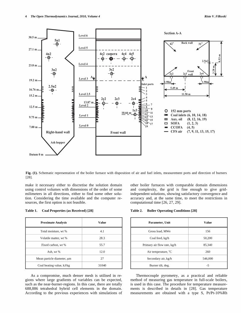
Some results of the numerical simulations, comparing
horizontal temperature profiles at different levels of the
boiler furnce obtained by the use of DO and P-1 radiation
models and measurements, as well, are presented in Figs. (3
and 4). The calculations were verified against the experimen-
tal data [28] and indicated good agreements in most cases,
with some acceptable discrepancies. The temperature pro-
files showed that the use of over-fire air altered the near-
burner temperatures, reducing the swirl relative to the incom-
ing fuel. Similar effects are also properly predicted near the
close-coupled over-fire air inlets. The general features of the
flow indicate the formation of vortex that have reduced tem-
perature levels at the middle of the furnace cross section in
some cases, which is probably a result of the adverse pres-
sure gradient.
Regarding the thermal radiation modelling approach,
both models, the DO and the P-1, give relatively fair repre-
sentationof the experimental results. In the most cases, the P-
1 model slightly overestimates the heat fluxes from localised
heat sources. However, it must be pointed out that the calcu-
lation using the DO model is more time consuming. The
ratio of the computing times using the models DO (with the
S6 approximation, which means 48 flux directions) and the
P1 is about 2.0. In the case of the DO with S4 approximation
(24 flux directions), the ratio of the computing times is 1.75.
Additional information on the results of the numerical
simulations, showing the influence of the two radiation models to other properties, such as the average furnace exit
temperature, the total heat transfer rate to the furnace
surfaces, char conversion at the furnace exit, etc., is given in Table 6.
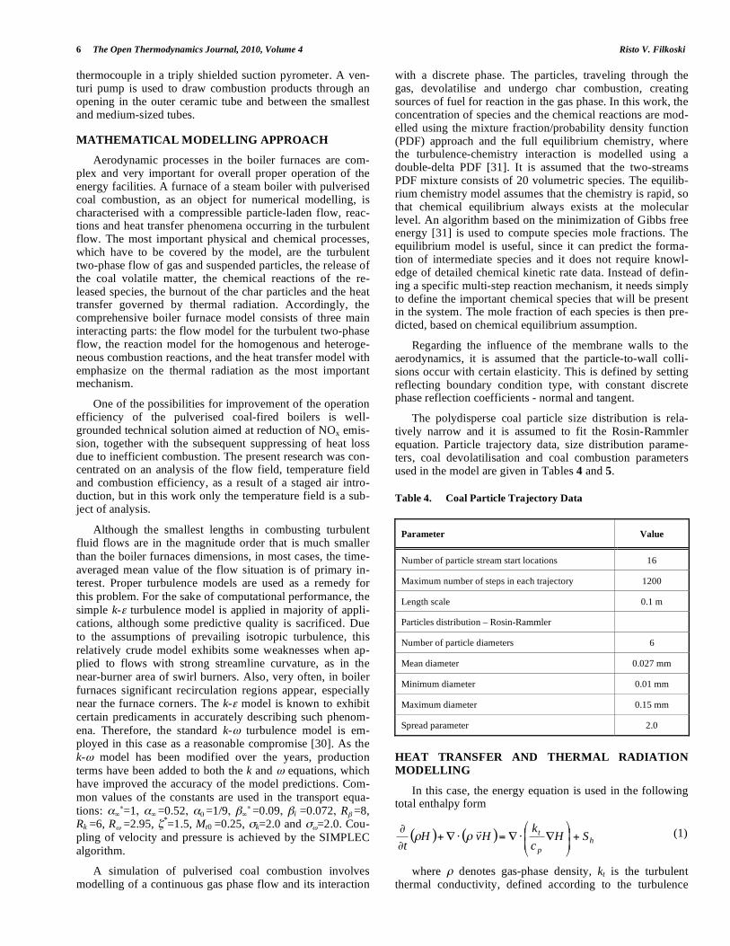
An illustration of the change of the area-weighted aver-
age volume fractions of O2 and CO along the furnace height is given in Fig. (5).
Profiles of the change of the total surface heat flux along the furnace height, obtained with the two radiation models, together with the average surface heat fluxes, denoted as P1-m and DO-m, are presented in Fig. (6).

Pulverised-Coal Combustion with Staged Air Introduction The Open Thermodynamics Journal, 2010, Volume 4 9
Fig. (3). Temperature profiles on the east (right-hand) wall for three levels of SOFA: a) Port 1e3, b) Port 2e2, c) Port 2e3, d) Port 2e4, e) Port
3e2, f) Port 4e4.
From the comparison of predicted and measured tem-peratures, the relatively high fluctuations of calculated tem-perature profiles, as well as certain discrepancies between the numerical predictions and measurements are obvious. The largest differences appear in the burnout zone, near the fuel and air inlets, and they can be put down to several pos-sible reasons. Such differences could indicate that the flow field in these areas may not be very well predicted. However,
there were no possibilities to check the quality of the on a basis of the available experimental results. Another reason may be the tendency of the P-1 model to over-predict radia-tive fluxes from localised heat sources, as it is suggested in [40]. Also, an important, but still relatively under-researched modelling area - the particles-turbulence interaction, could be a reason for appearance of differences between the calcu-lated and measured temperature profiles. Finally, it must be
Port 1e3
400
600
800
1000
1200
1400
1600
0 1 2 3 4
Depth, m
Tem
pera
ture
, o C
CFD-DOCFD-P1Measurements
a)
Port 2e2
400
600
800
1000
1200
1400
1600
1800
0 1 2 3 4
Depth, m
Tem
pera
ture
, o C
CFD-DOCFD-P1Measurements
b)
Port 2e3
400
600
800
1000
1200
1400
1600
0 0,5 1 1,5 2 2,5 3 3,5 4 4,
Depth, m
Tem
pera
ture
, o C
CFD-DOCFD-P1Measurements
5
c)
Port 2e4
400
600
800
1000
1200
1400
1600
0 0,5 1 1,5 2 2,5 3 3,5 4 4,5
Depth, m
Tem
pera
ture
, o C
CFD-DOCFD-P1Measurements
d)
Port 3e2
400
600
800
1000
1200
1400
1600
0 0,5 1 1,5 2 2,5 3 3,5 4 4,5
Depth, m
Tem
pera
ture
, o C
CFD-DOCFD-P1Measurements
e)
Port 4e4
400
600
800
1000
1200
1400
1600
0 0,5 1 1,5 2 2,5 3 3,5 4 4,5
Depth, m
Tem
pera
ture
, o C
CFD-DOCFD-P1Measurements
f)
10 The Open Thermodynamics Journal, 2010, Volume 4 Risto V. Filkoski
Fig. (4). Temperature profiles on the north wall for three levels of SOFA: a) Port 2.5n2, b) Port 3n2, c) Port 4n2, d) Port 5n1.
Fig. (5). Area-weighted average volume fractions of O2 and CO
along the furnace height.
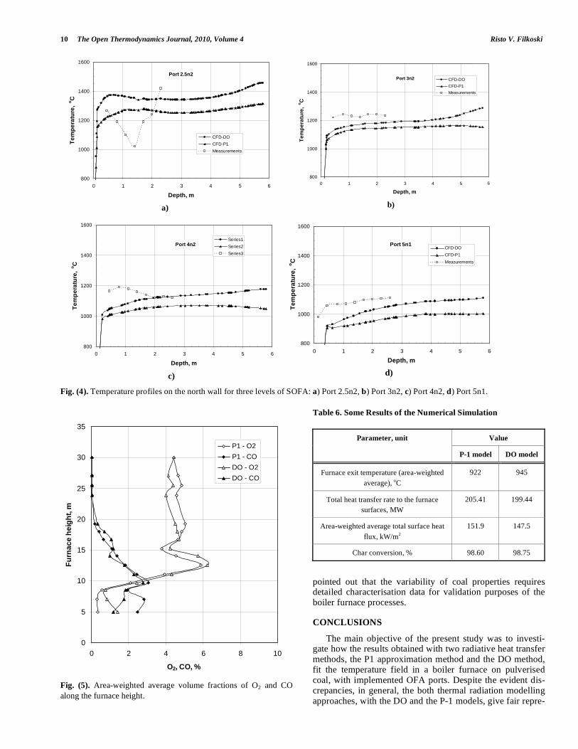
Table 6. Some Results of the Numerical Simulation
Value Parameter, unit
P-1 model DO model
Furnace exit temperature (area-weighted
average), oC
922 945
Total heat transfer rate to the furnace
surfaces, MW
205.41 199.44
Area-weighted average total surface heat
flux, kW/m2
151.9 147.5
Char conversion, % 98.60 98.75
pointed out that the variability of coal properties requires detailed characterisation data for validation purposes of the boiler furnace processes.
CONCLUSIONS
The main objective of the present study was to investi-gate how the results obtained with two radiative heat transfer methods, the P1 approximation method and the DO method, fit the temperature field in a boiler furnace on pulverised coal, with implemented OFA ports. Despite the evident dis-crepancies, in general, the both thermal radiation modelling approaches, with the DO and the P-1 models, give fair repre-
Port 2.5n2
800
1000
1200
1400
1600
0 1 2 3 4 5 6
Depth, m
Tem
pera
ture
, o C
CFD-DOCFD-P1Measurements
a)
Port 3n2
800
1000
1200
1400
1600
0 1 2 3 4 5
Depth, m
Tem
pera
ture
, o C
6
CFD-DOCFD-P1Measurements
b)
Port 4n2
800
1000
1200
1400
1600
0 1 2 3 4 5 6
Depth, m
Tem
pera
ture
, o C
Series1Series2Series3
c)
Port 5n1
800
1000
1200
1400
1600
0 1 2 3 4 5
Depth, m
Tem
pera
ture
, o C
6
CFD-DOCFD-P1Measurements
d)
0
5
10
15
20
25
30
35
0 2 4 6 8
O2, CO, %
Furn
ace
heig
ht, m
10
P1 - O2P1 - CODO - O2DO - CO

Pulverised-Coal Combustion with Staged Air Introduction The Open Thermodynamics Journal, 2010, Volume 4 11
sentation of the experimental results. The obtained tempera-ture profiles with P-1 model are somewhat lower than in the case when the DO model is used. In that sense, the results obtained with the DO model better fit the measurements. The main differences between the modelling and the measure-ment values appear in the burnout zone, near the air/fuel injections, and need further investigation for appropriate explanation. In general, they can be addressed to several reasons: peculiarities of the flow field in the near-burner region, including the particles-turbulence interaction; the utilised thermal radiation models; and the variability of coal properties that requires much characterisation data for validation purposes of the boiler furnace processes. Finally, it must be noted that the computation with the DO model is more time consuming.
REFERENCES
[1] U. Schnell, “Numerical modelling of solid fuel combustion
processes using advanced CFD-based simulation tools”, Progress
in Computational Fluid Dynamics, Vol. 1, No. 4, pp. 208-218,
2001.
[2] L. I. Diez, C. Cortes, A. Campo, “Modelling of pulverised coal
boilers: review and validation of on-line simulation techniques”,
Applied Thermal Engineering, 25, pp. 1516-1533, 2005.
[3] N. V. Kuznetsov, V. V. Mitor, I. E. Dubovskiy, Ye. S. Karasina,
M. M. Rubin, A. G. Blokh, Yu. L. Marshak, R. A Petrosyan, V. A.
Lokshin, S. I. Mochan, P. N., Eds. Teplovoy raschet kotelynyih
agregatov (Normativniy metod), Izd. Energiya, Moskva – Lenin-
grad, 1973.
[4] Y. A. Zhuravlev, F. K. Sidorov, M. Y. Protsaylo, “Primenenie
zonalynogo metoda dlya rascheta teploobmena v topke kotla”,
Teploenergetika, No 11, pp. 35-39, 1980.
[5] M. Y. Protsaylo, Y. A. Zhuravlev, “Issledovanie zonalynyim
metodom vliyaniya rezhimnyih parametrov na teploobmen v topke
kotla P-67”, Teploenergetika, No. 4, pp. 13-16, 1983.
[6] H. C. Hottel, A. F. Sarofim, Radiative Transfer, McGraw-Hill,
USA, 1967. [7] G. Blokh. Heat Transfer in Steam Boiler Furnaces, London,
Hemisphere Publishing, 1988. [8] P. Ustimenko, K. B. Dzhakupov, V. O. Kroly, Chislennoe modeli-
rovanie aerodinamimki i goreniya v topochnyih i tehnologicheskih ustroystvah, Izd. “Nauka”, Alma Ata, 1986.
[9] W. Fiveland, A. R. Wessel, “Numerical model for predicting per-formance of three-dimensional pulverized-fuel fired furnaces”,
Journal of Engeneering for Gas Turbines and Power, Vol. 110(11), pp. 117-126, 1988.
[10] J. Fan, L. Qian, Y. Ma, P. Sun, K. Cen, “Computational modelling of pulverized coal combustion processes in tangentially fired fur-
naces”, Chemical Engineering Journal, Vol. 81(1), pp. 261-269, 2001.
[11] J. M. Jones, M. Pourkashanian, A. Williams, R. K. Chakraborty, J. Sykes, D. Laurence, “Modelling of coal combustion processes - a
review of present status and future needs”, In Proc. 15th Annu. Intern. Pittsburgh Coal Conf. Pittsburgh, 1998; pp. 1-20.
[12] M. Eaton, L. D. Smoot, S. C. Hill, C. N. Eatough, “Components, formulations, solutions, evaluation, and application of comprehen-
sive combustion models”, Progress in Energy and Combustion Science, Vol. 25(4), pp.387–436, 1999.
[13] L. D. Smoot, “A decade of combustion research. Progress in Energy and Combustion Science, Vol. 23(3), pp.203-232, 1997.
[14] L. D. Smoot, “International Research Centers’ Activities in Coal Combustion”, Progress in Energy and Combustion Science, Vol.
24, pp.409-501, 1998. [15] R. K. Boyd, J. H. Kent, “Three-dimensional furnace computer
modelling”, Proceedings of the 21st Symposium (Int.) on Combus-tion, The Combustion Institute, Pittsburgh, 1986, pp. 265-274.
[16] S. C. Hill, L. D. Smoot, “A comprehensive three-dimensional model for simulation of combustion systems: PCGC-3”, Energy &
Fuels, Vol. 7(6), pp.874-883, 1993. [17] X. Y. Zhou, C. G. Zheng, Y. Y. Ma, “comparison of several
discrete arithmetic schemes for simulating a constrained jet and a lab-scale tangential fired furnace”, Computer Methods in Applied
Mechanics and Engineering, Vol. 130(3-4), pp.279-288, 1996. [18] A. Bermudez de Castro, J. L. Ferin, “Modelling and numerical
solution of a pulverized coal furnace”, Proceedings of the 4th
International Conference on Technologies and Combustion for
Clean Environment, Lisbon, Portugal, paper 33.1, 1997, pp. 1-9. [19] L. X. Zhou, L. Li, R. X. Li, J. Zhang, “Simulation of 3-d
gas-particle flows and coal combustion in a tangentially fired furnace using a two-fluid-trajectory model”, Powder Technology,
Vol. 125(2), pp. 226-233, 2002. [20] Yin, S. Caillat, J. L. Harion, B. Baudoin, E. Perez, “Investigation of
the flow, combustion, heat-transfer and emissions from a 609 mw utility tangentially fired pulverized coal boiler”, Fuel, Vol. 81(8),
pp.997-1006, 2002. [21] W. A. Fiveland, “Three-dimensional radiative heat-transfer solu-
tions by the discrete-ordinates method”, Journal of Thermophysics, Vol. 2, No. 4, pp. 309-316, Oct. 1988.
[22] He, M. Chen, Q. Yu, S. Liu, L. Fan, S. Sun, J. Xu, W. P. Pan, “Numerical study of the optimum counter-flow mode of air jets in a
large utility furnace”, Computers & Fluids, Vol. 33 (9), pp.1201-1223, 2004
[23] J. Pallares, I. Arauzo, A. Williams, “Integration of CFD codes and advanced combustion models for quantitative burnout determina-
tion”, Fuel, Vol. 86, No. 15, pp. 2283-2290, Oct. 2007. [24] H. Knaus, U. Schnell, K.R.G. Hein, “On the modelling of
coal combustion in a 550 MWel coal-fired utility boiler”, Progress in Computational Fluid Dynamics, Vol. 1, No. 4, pp. 194-207,
2001. [25] C. Ratzel III, J. R. Howell, “Two-dimensional radiation in
absorbing-emitting media using the p-n approximation”, Journal of Heat Transfer, Transactions of the ASME, Vol. 105, pp.333-340,
1983. [26] R. V. Filkoski, I. J. Petrovski, P. Karas, “Optimisation of pulver-
ised coal combustion by means of CFD/CTA modelling”, Thermal Science (An International Journal), Vol. 10, No. 3, pp.161-179,
2006. [27] R. V. Filkoski, S. V. Belosevic,, I. J. Petrovski, S. N. Oka, M. A.
Sijercic, “Cfd technique as a tool for description of the phenomena occurring in pulverised coal combustion systems”, Proc. IMechE,
Journal of Power and Energy, Vol. 221 Part A: pp.399-409, 2007.
Fig. (6). Area-weighted average total surface heat flux along the
furnace height.
0
4
8
12
16
20
24
28
32
20 60 100 140 180 220 260 300Surface heat flux, kW/m2
Furn
ace
heig
ht, m
P1DOP1-mDO-m

12 The Open Thermodynamics Journal, 2010, Volume 4 Risto V. Filkoski
[28] R. Tree, B. W. Webb, “Local temperature measurements in a
full-scale utility boiler with overfire air”, Fuel, Vol. 76, No. 11, pp. 1057-1066, 1997.
[29] R. V. Filkoski, “Modelling of thermal processes and optimisation of energetic-environmental characteristics of modern boiler plants”,
Ph.D. thesis, University “Ss Cyril and Methodius”, Skopje, 2004. [30] C. Wilcox, Turbulence Modelling for CFD, second ed., DWC
Industries, La Canada, California, 1998. [31] K. Kuo, Principles of Combustion, John Wiley & Sons, New York
- Chichester - Brisbane - Toronto - Singapore, 1986. [32] E. Khalil, Modelling of Furnaces and Combustors, Abacus Press,
Tunbridge Wells, Kent, 1982. [33] R. Siegel, J. R. Howel, Thermal Radiation Heat Transfer,
Hemisphere Publ. Corp., Washington D.C., 1992. [34] Zh. Guo, S. Kumar, “Three-dimensional discrete ordinates method
in transient radiative transfer”, Journal of Thermophysics and Heat Transfer, Vol. 16, No. 3, pp. 289-296, July-September 2002.
[35] Dorri-Nowkoorani, R. I. Dougherty, “Modified pn for correlation
transfer in one-dimensional scattering and absorbing media”, Journal of Thermophysics and Heat Transfer, Vol. 16, No. 4,
pp. 529-536, Oct.-Dec. 2002. [36] N. G. Shah, “A new method of computation of radiant heat transfer
in combustion chambers”, Ph.D. Thesis, Imperial College of Science and Technology, London, 1979
[37] G. Blokh, Y. A. Kuravlev, L. N. Ryzhkov, Teploobmen izluche-niem, Energoatomizdat, Moskva, 1991
[38] J. Rusas, “Numerical simulation of gas-particle flow linked to pulverized coal combustion”, Ph.D. Thesis, Inst. of Energy
Technology, Aalborg University, Aalborg, Denmark, 1998 [39] M. F. Modest, “The weighted-sum-of-gray-gases model for
arbitrary solution methods in radiative transfer”, Journal of Heat Transfer, Vol. 113, No. 3, pp. 650-656, August 1991.
[40] Fluent 6.1 User’s Guide, Fluent Inc., Lebanon NH, USA, 2003.
Received: August 31, 2009 Revised: October 13, 2009 Accepted: October 13, 2009
© Risto V. Filkoski; Licensee Bentham Open.
This is an open access article licensed under the terms of the Creative Commons Attribution Non-Commercial License (http://creativecommons.org/licenses/by-nc/3.0/) which permits unrestricted, non-commercial use, distribution and reproduction in any medium, provided the
work is properly cited.
Related Documents