Guide Presented by Mr.M Cheenya V.Abhinav Kumar 11E31A0422 Asst.Professor K.Shiva Kumar 11E31A0423 K.Rajashekhar 11E31A0424 K.Chaithanya Sree 11E31A0428 K.Pramitha 11E31A0429

PULSE WIDTH MODULATION &DEMODULATION
Jul 16, 2015
Welcome message from author
This document is posted to help you gain knowledge. Please leave a comment to let me know what you think about it! Share it to your friends and learn new things together.
Transcript
Guide Presented by
Mr.M Cheenya V.Abhinav Kumar 11E31A0422
Asst.Professor K.Shiva Kumar 11E31A0423
K.Rajashekhar 11E31A0424
K.Chaithanya Sree 11E31A0428
K.Pramitha 11E31A0429
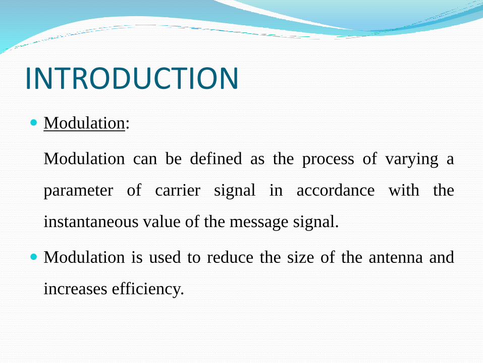
INTRODUCTION Modulation:
Modulation can be defined as the process of varying a
parameter of carrier signal in accordance with the
instantaneous value of the message signal.
Modulation is used to reduce the size of the antenna and
increases efficiency.
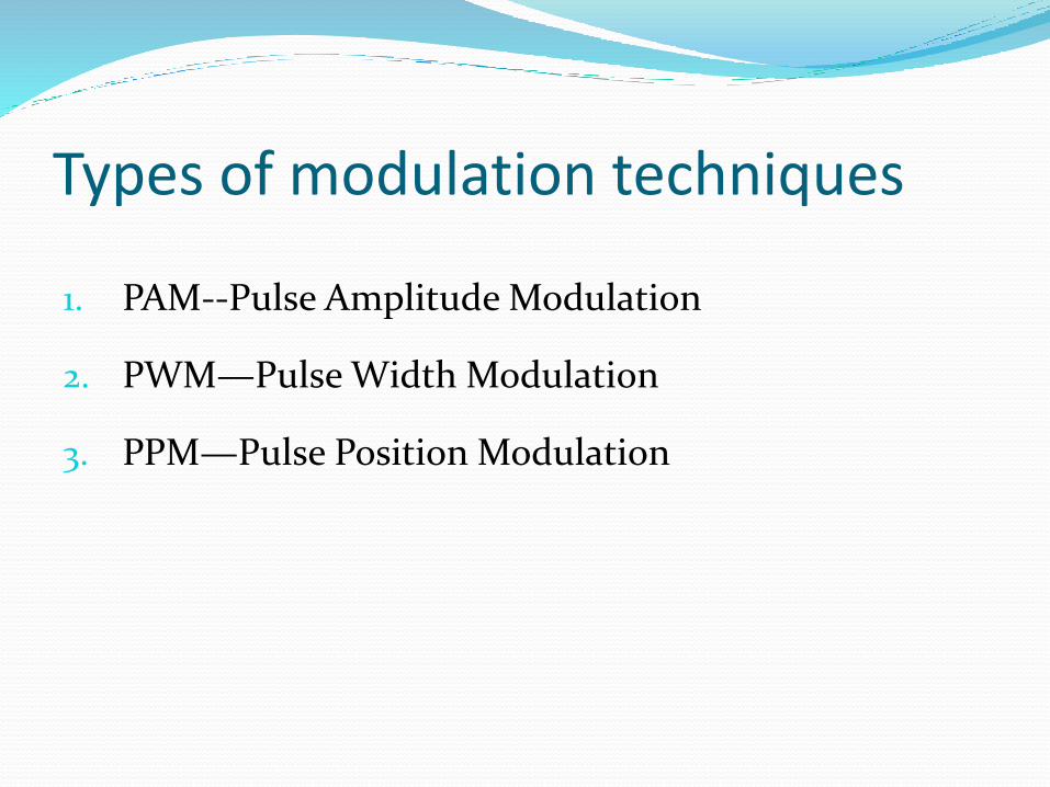
Types of modulation techniques
1. PAM--Pulse Amplitude Modulation
2. PWM—Pulse Width Modulation
3. PPM—Pulse Position Modulation
What is PWM…? Pulse width modulation is a technique that generates
variable width signal generally based on modulator signal
information.
The general purpose of PWM is to control power delivery.
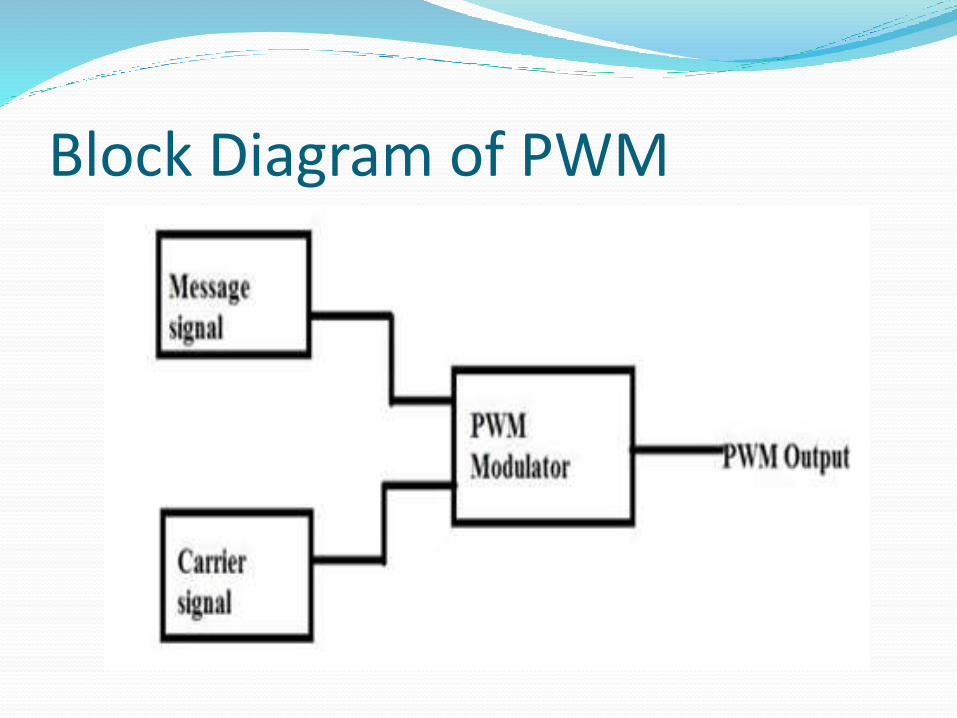
Block Diagram of PWM
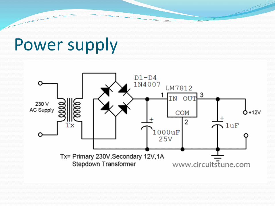
Power supply
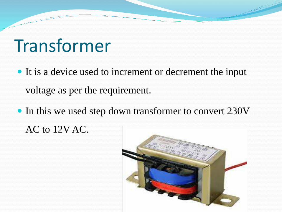
Transformer It is a device used to increment or decrement the input
voltage as per the requirement.
In this we used step down transformer to convert 230V
AC to 12V AC.
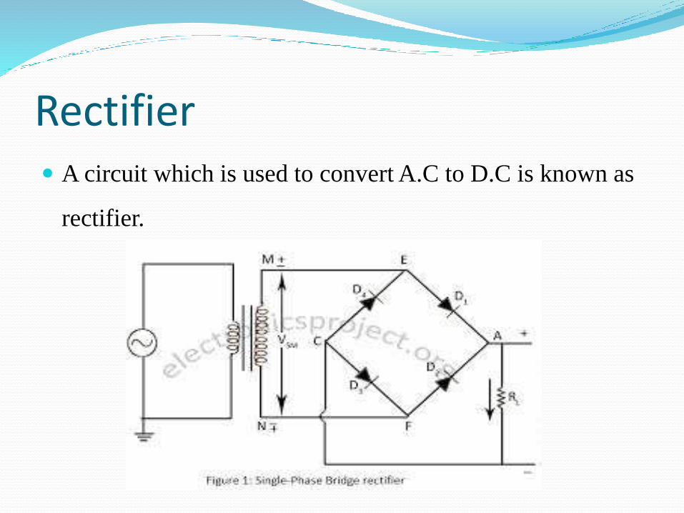
Rectifier A circuit which is used to convert A.C to D.C is known as
rectifier.
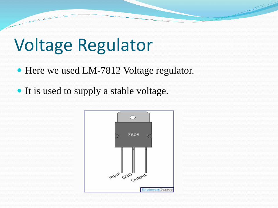
Voltage Regulator Here we used LM-7812 Voltage regulator.
It is used to supply a stable voltage.
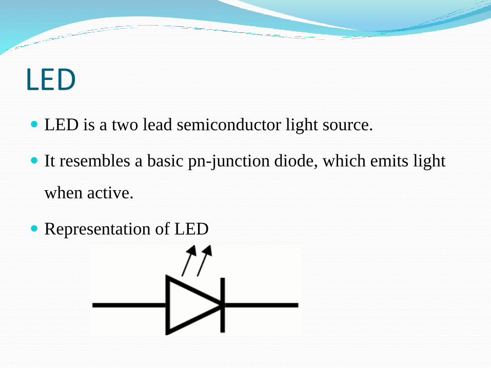
LED LED is a two lead semiconductor light source.
It resembles a basic pn-junction diode, which emits light
when active.
Representation of LED
Pulse width modulation
PWM is a modulation technique, which converts an
analog signal into a digital signal for transmission.
PWM converts an audio signal into a sequence of pulses
having constant amplitude, but the width is proportional to
amplitude of an audio signal.
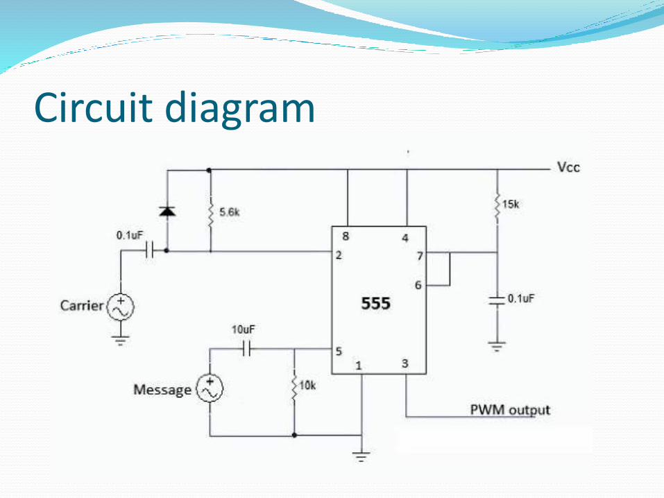
Circuit diagram
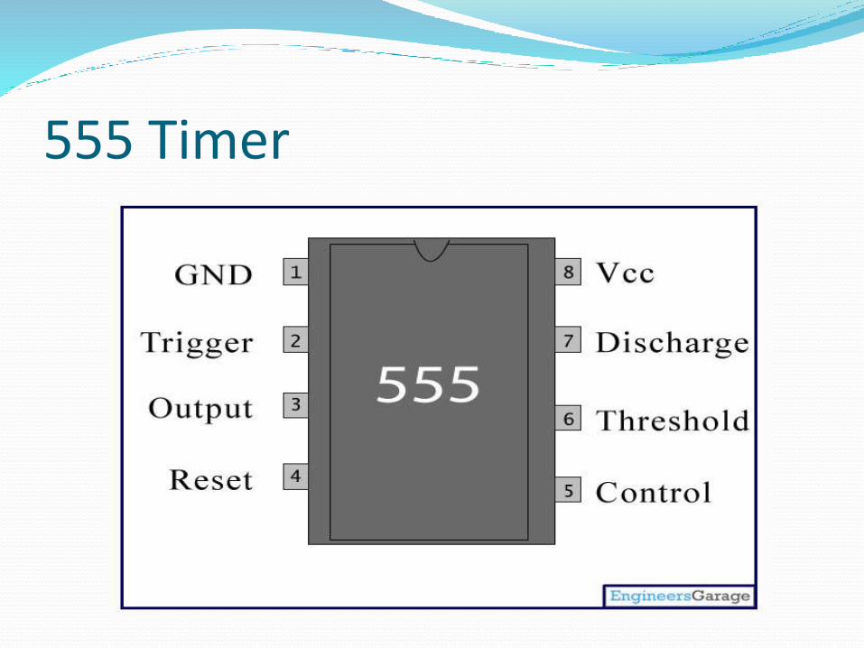
555 Timer
Features of IC 555
Maximum operating voltage 16V.
Operates in the temperature range of -55 to 125 degrees.
Maximum output current 200mA.
8-pin metal can.
Applications of 555 timer
Ramp and Square wave generator.
Frequency dividers.
Voltage controlled oscillators.
Pulse generators .
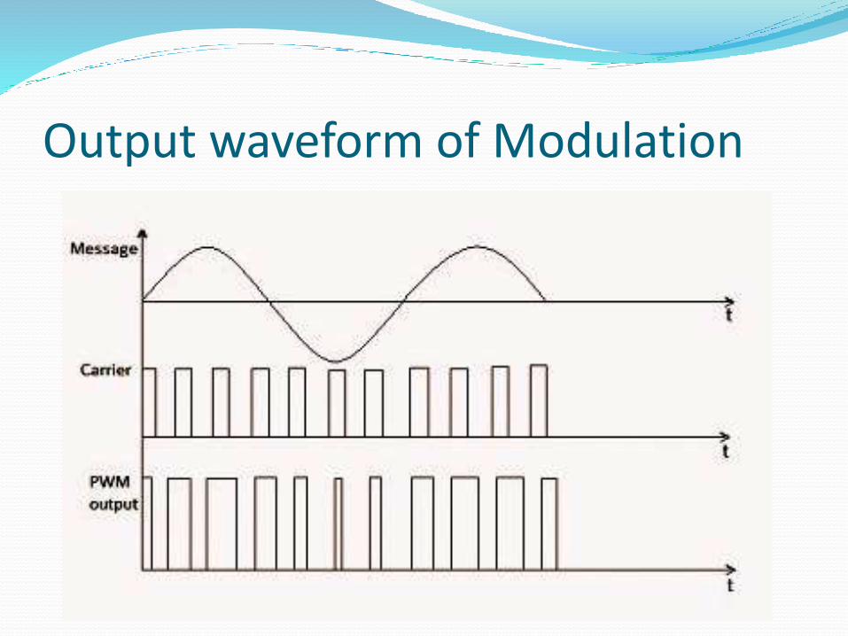
Output waveform of Modulation
Demodulation Demodulation is the act of extracting the original
information bearing signal from a modulated carrier wave.
It is used to recover the information content from the
modulated carrier wave.
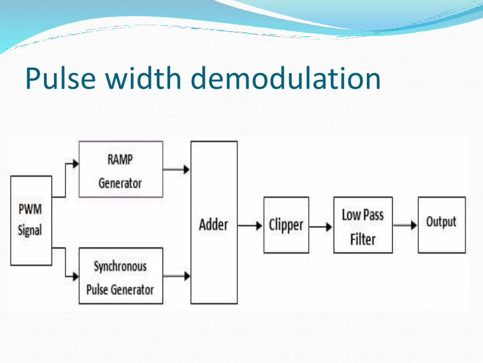
Pulse width demodulation
Working of demodulation The regenerated PWM is then applied to the ramp
generator & synchronization generator.
The ramp generator produces ramps for the duration of
pulses such that height of ramps are proportional to the
width of ramp pulses.
Synchronous pulse generator produces references pulses
with constant amplitude and pulse width.
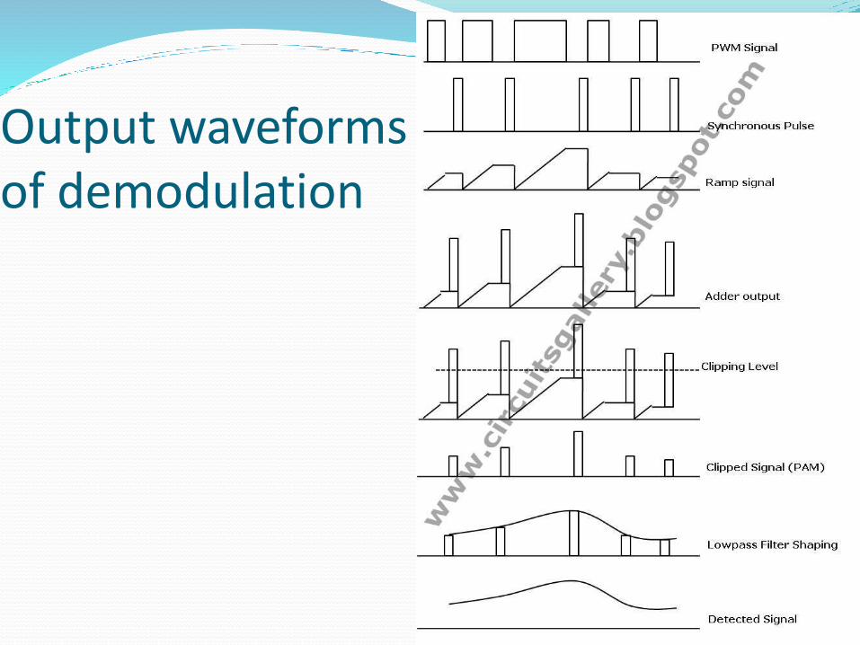
Output waveforms of demodulation

Results Input waveform
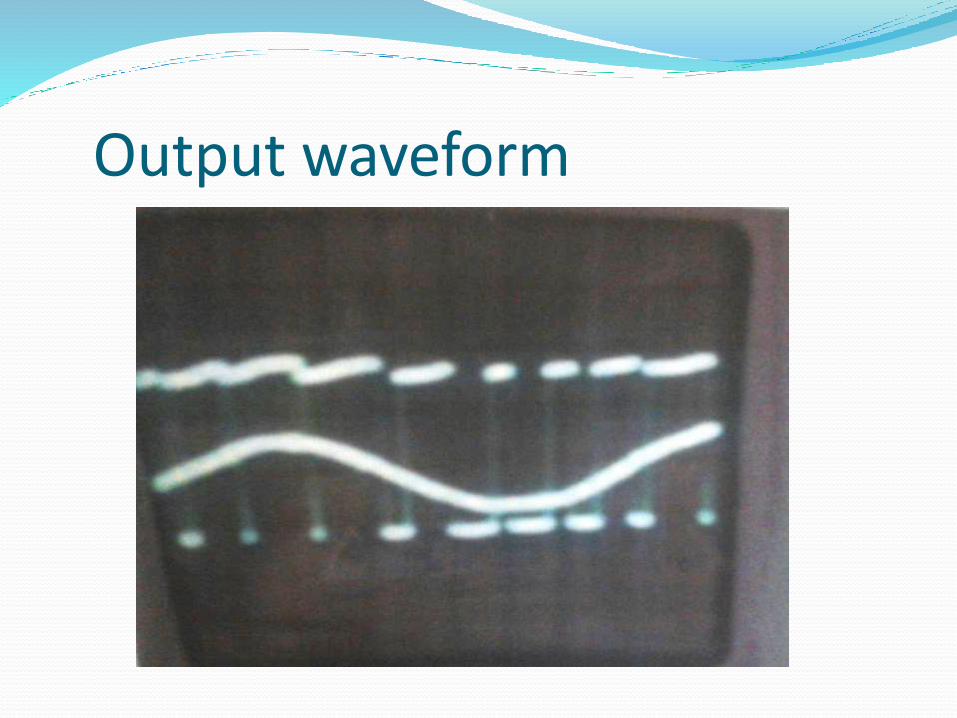
Output waveform
Advantages Low Noise
Low power consumption
High efficient
Does not require synchronization between transmitter and receiver.
Applications
Telecommunications
Voltage regulation
Power delivery
Amplification
Use as ADC
Conclusion The design of a compact circuit board with good track
routing requires experience in PCB design.
With the help of protel software the kit is developed and
can be used as an experimental kit, it provides user
friendly environment for the users.

THANK YOU
Related Documents