Prvnto of -pieWerb 04 4-. t4 4 -~0 * 0S 6Ox Fia Reor0 t Conrac No 000476C0 0anjiSk yoCo i

Welcome message from author
This document is posted to help you gain knowledge. Please leave a comment to let me know what you think about it! Share it to your friends and learn new things together.
Transcript

Prvnto of -pieWerb
044-. t4
4 -~0 * 0S 6Ox
Fia Reor0 t
Conrac No 000476C0
0anjiSk
yoCo i

41
LMP/TRB-8O-02
PREVENTION OF SPLINE WEAR BYSOFT METALLIC COATINGS
Final Report toThe Defense Advanced Research Projects Agency
andThe Office of Naval Research
Contract No. N00014-76-00068
Nannaji SakaHyo-Chol SinNam P. Suh
Laboratory for Manufacturing and Productivity
Massachusetts Institute of TechnologyCambridge, Massachusetts 02139
July 1980
I hpprov.rI for POd hr, relea3.Distril u-ier Ur,undted

SECURITY CLASSIFICATION Trtmi *A" M Dits not0er-
REPORT DOCUMENTATION PAGE RMI. REPORT NUMBER {ZOVT ACCESSIO NO2 ECiPiEn
A. TITLE (ed Subtitle) S.-~ '~ TYPE 0 00 COERED
'Prevention of Spline Wear by Soft Metallic January 1, 1977 - LSCoatings . -" ".. ...... . .. "f . S6. PERFORMING ORGI. REPO IT NUMBER
CONTRA T R Re
a:nnaj'i/aka oq-,CholjSin m Na P Suh I o14-76- 81N!,nna4i~~~~h1~i C_
9. PERFORMING ORGANIZATION NAME AND ADDRESS 10. PROGRAM ELEMENT, PROJECT, TASK
Laboratory for Manufacturing and Productivity AREA & WORK UNIT NUMBERS
Massachusetts Institute of Technology ---
77 Massachusetts Ave., Cambridge, MA 0213911. CONTROLLING OFFICE NAME AND ADDRESS a--ralOffice of Naval Research J~"
Department of the Navy O SArlington, VA 22217 C
14. MONITORING AGENCY NAME a ADDRESS(II difelrt from Controllinj Office) IS. SECURITY CLASS. (of this report)
M.I.T. Resident Representatiys---UnclassifiedOffice of Naval ResearchRoom E19-628 M.I.T. ( " ISO. OECLASSIFlCATION/OOmGRAOING77 Massachusetts Ave., Cambridge, MA 02139 SCHEDULE
IS. DISTRIBUTION STATEMENT (of thle Report)Unlimited
17. DISTRIBUTION STATEMENT (of Clio abstrc entered in Block 20, If different hem Repo")
I. SUPPLEMENTARY NOTES
IS. KEY WORDS (Continue on reveres side if noceosarye nd Identify by block number)
spline wear, fretting, delamination wear, soft metallic coatings,ferrogram, wear particles
20. ABSTRACT (Continue on revers ef do It noceoew mid identify by block number)
The purpose of this cooperative program between MIT, Naval Air Devel-opment Center (NADC) and Foxboro-Analytical is to study the mechanism ofwear and increase the wear resistance of aircraft splines. In addition totesting a much larger number of splines under a variety of conditions thanhas been done so far, optical microscopy, scanning electron microscopy andferrography have been extensively used to identify the wear mechanism.
Test specimens of aircraft splines were coated with Au, Ni, Ag and Cd
DD I'j 73 1473 EDITION OF NOV 65 OBSOLE E UnclassifiedS/N 0102-014- 6601
SECURITY CLASSIFICATION OF THIS PAGE (When Date Entr ,
...............................- , . .........
. ,.. U .TY

Unclassified. T CLASSIFICATION OF THIS PAGE(IWhw Data Entr,.d)
(Block 20 continued)
with various thicknesses (0.1 - 10 pm) and tested in the SwRI spline weartester with and without grease. The gold coated splines exhibited inductionperiods of 250 hours, which is four times that exhibited by the uncoatedsplines. Ni, Ag and Cd failed to increase the induction period. Unlubri-cated splines wore exactly at the same rate as the post-induction wear ratesof the grease lubricated splines.
Optical and scanning electron microscopy results indicate that themode of wear is by subsurface deformation, crack nucleation and growth pro-cesses (i.e., by the delamination mechanism) both in the induction and thepost-induction periods.
Analysis of the splines by the energy dispersive X-ray analysis showedthat the metallic coatings did not react with grease. This and other evi-dence indicates that the coating/substrate bond strength is an importantfactor in the wear of splines. Methods for improving the bond strength andreducing the cost of the coatings are suggested.
,..L
NiTIS GPA')DTIC I
AvP.
DCAlt
saCuRITY CLASPPFICA?,@N OF THIS PA~Gruv..e Dole aw,.,
.... . . . . . . . ..,~ .

3
Abstract
The purpose of this cooperative program between MIT, Naval Air
Development Center (NADC) and Foxboro-Analytical is to study the mech-
anism of wear and increase the wear resistance of aircraft splines.
In addition to testing a much larger number of splines under a variety
of conditions than has been done so far, optical microscopy, scanning
electron microscopy and ferrography have been extensively used to iden-
tify the wear mechanism. J.
Test specimens of aircraft splines were coated with Au, Ni, Ag
and Cd with various thicknesses (0.1 - 10(p') and tested in the SwRI
spline wear tester with and without grease. The gold coated splines
exhibited induction periods of 250 hours, which is four times that
exhibited by the uncoated splines. Ni, Ag and Cd failed to increase
the induction period. Unlubricated splines wore exactly at the same
rate as the post-induction wear rates of the grease lubricated splines.
Optical and scanning electron microscopy results indicate that
the mode of wear is by subsurface deformation, crack nucleation and
growth processes (i.e., by the delamination mechanism) both in the
induction and the post-induction periods.
Analysis of the splines by the energy dispersive X-ray analysis
showed that the metallic coatings did not react with grease. This and
other evidence indicate that the coating/substrate bond strength is an
important factor in the wear of splines. Methods for improving the
bond strength and reducing the cost of the coatings are suggested.
lopl"i
ir~ ~ ~ ~~~I RU N I I M-'- ~'ill -. '
4
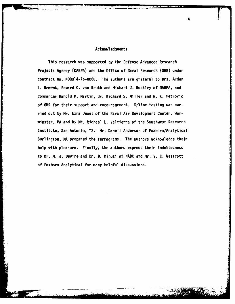
Acknowledgments
This research was supported by the Defense Advanced Research
Projects Agency (DARPA) and the Office of Naval Research (ONR) under
contract No. NOOO14-76-0068. The authors are grateful to Drs. Arden
L. Bement, Edward C. van Reuth and Michael J. Buckley of DARPA, and
Commander Harold P. Martin, Dr. Richard S. Miller and W. K. Petrovic
of ONR for their support and encouragement. Spline testing was car-
ried out by Mr. Ezra Jewel of the Naval Air Development Center, War-
minster, PA and by Mr. Michael L. Valtierra of the Southwest Research
Institute, San Antonio, TX. Mr. Daneil Anderson of Foxboro/Analytical
Burlington, MA prepared the ferrograms. The authors acknowledge their
help with pleasure. Finally, the authors express their indebtedness
to Mr. M. J. Devine and Dr. D. Minuti of NADC and Mr. V. C. Westcott
of Foxboro Analytical for many helpful discussions.
""F t . .. . ... . '
5
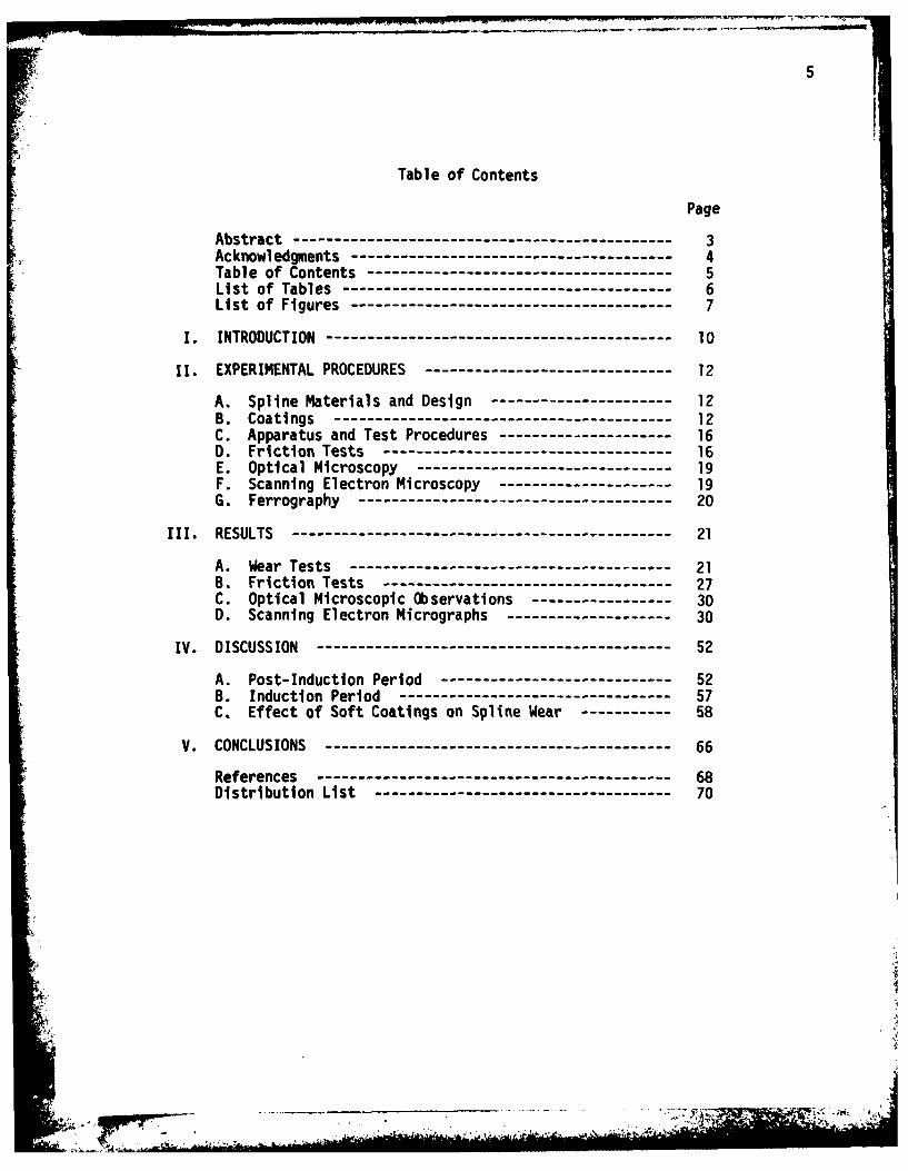
Table of Contents
Page
Abstract ------------------------------------------- 3Acknowledgments------------------------------------- 4Table of Contents----------------------------------- 5List of Tables-------------------------------------- 6List of Figures------------------------------------- 7
I. INTRODUCTION --------------------------------------- 10
II. EXPERIMENTAL PROCEDURES----------------------------- 12
A. Spline Materials and Design ---------------------- 12B. Coatings--------------------------------------- 12C. Apparatus and Test Procedures --------------------- 160. Friction Tests --------------------------------- 16E. Optical Microscopy------------------------------ 19F. Scanning Electron Microscopy --------------------- 19G. Ferrography------------------------------------ 20
111. RESULTS---------------------------------- --------- 21
A. Wear Tests------------------------------------- 21B. Friction Tests --------------------------------- 27C. Optical Microscopic Observations------------------ 300. Scanning Electron Micrographs -------------------- 30
IV. DISCUSSION ---------------------------------------- 52
A. Post-Induction Period--------------------------- 52B. Induction Period ------------------------------- 57C. Effect of Soft Coatings on Spline Wear-------------58
V. CONCLUSIONS --------------------------------------- 66
References ---------------------------------------- 68
Distribution List ---------------------------------- 70
.ILI

6
List of Tables
Table Page
1. Spline Design Parameters 13
11. Test Conditions 18
III. Friction Coefficients of Uncoated and Coated Splines 2
IV. Vickers Microhardness of Coatings 6
7
List of Figures
FigureNo. Title Page
1 Test splines: (a) internal spline and (b) 14external spline.
2 Microstructure of hardened splines: (a) in- 15ternal spline and (b) external spline.
3 Spline wear tester. 17
4 Wear of gold-coated splines as a function 22of test time.
5 Wear of nickel-coated splines as a func- 23tion of test time.
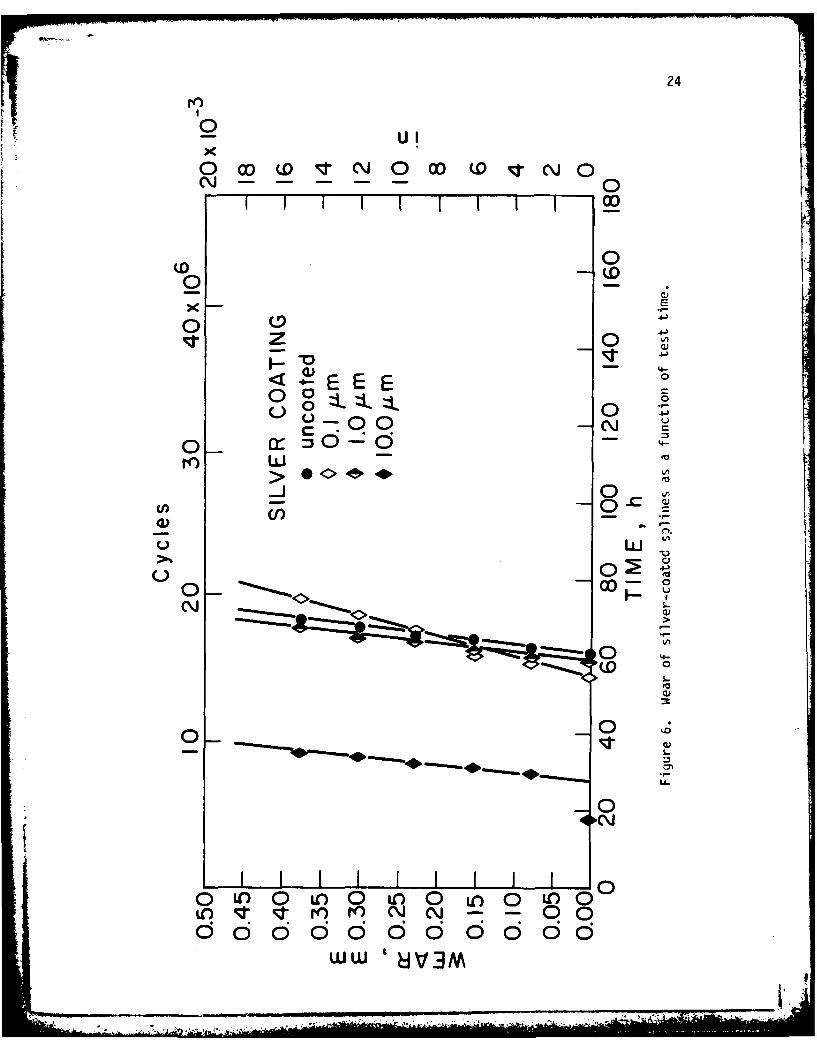
6 Wear of silver-coated splines as a function 24of test time.
7 Wear of cadmium-coated splines as a func- 25tion of test time.
8 Induction period versus coating thickness. 26
9 Post-induction period versus coating thickness. 28
10 Optical micrographs of untested and worn 31splines: (a) as machined spline (b) testedto 0.4 mm wear without coating, (c) gold-coated spline tested to 0.4 mm of total wear.
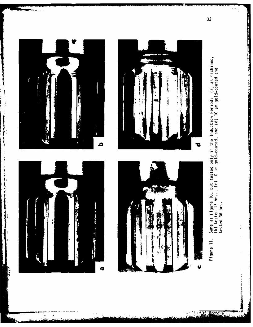
11 Same as Figure 10, but tetted only in the in- 32duction period: (as machined, (b) tested17 hrs., (c) 10 pm gold-coated, and (d)10 Um gold-coated and tested 36 hrs.
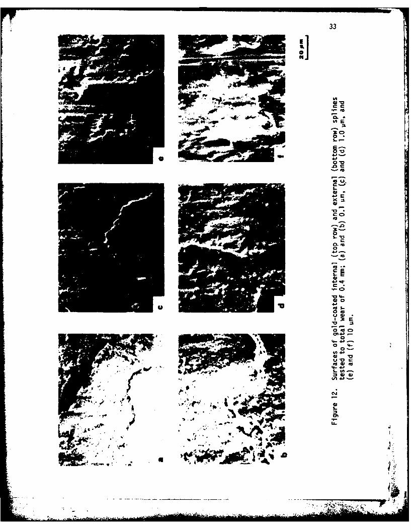
12 Surfaces of gold-coated internal (top row) 33and external (bottom row) splines testedto total wear of 0.4 m; (a) and (b) 0.1 um,(c) and (d) 1.0 vim, and (e) and (f) 10 umo.
13 Surfaces of nickel-coated internal (top row) 34and external (bottom row) splines tested toa total wear of 0.4 mm. Other details arethe same as in Figure 12.
14 Surfaces of silver-coated internal (top row) 35and external (bottom row) splines tested toa total wear of 0.4 mm. Other details arethe same as in Figure 12.
* . I-.-
8
FigureNo. Title Page
15 Surfaces of cadmium-coated internal (top 36row) and external (bottom row) splinestested to a total wear of 0.4 mm. Otherdetails are the same as In Figure 12.
16 Scanning electron micrographs of the sur- 38faces: (a) internal and (b) externalas machined splines; (c) internal and(d) external splines tested in the induc-tion period (17h).
17 Surface of gold-coated (10 um) spline 39tested only in the induction period (209h):(a) internal spline and (b) externalspline.
18 Subsurface of 10 um gold-coated spline 40after 0.4 mm total wear: (a) internalspline and (b) external spline.
19 Subsurface of 10 um nickel-coated spline 41after 0.4 mm total wear: (a) internalspline and (b) external spline.
20 Subsurface of 10 um silver-coated spline 42after 0.4 mm total wear: (a) internalspline and (b) external spline.
21 Subsurface of 10 um cadmium-coated spline 43after 0.4 mm total wear: (a) Internalspline and (b) external spline.
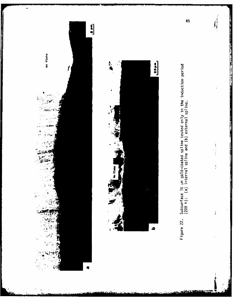
22 Subsurface 10 jAm gold-coated spline 45tested only in the induction period (209h):(a) internal spline and (b) externalspline.
23 Wear particles of splines coated with 4610 Um (a) Au, (b) Ni, (c) Ag, and (d) Cdand tested to 0.4 mm total wear.
24. Wear particles of splines (coated with 4710 um gold) after 0.4 mm total wear:(a) unpolarized and (b) polarized light.
25 Wear particles of uncoated splines. (a) 48after 0.4 mm wear and (b) In the induc-tion period (17h).
U- - -
9
FigureNo. Title Page
26 Wear particles of splines coated with 4910 um gold and tested in the inductionperiod (209h). (a) white light and(b) bichromatic light.
27 Ferrograms of the grease used in the 51spline tests. (a) entry and (b) at 27 mmon the ferrogram.
28 Total wear of unlubricated and lubricated 53splines as a function of test time. (a)unlubricated and uncoated, (b) unlubri-cated and gold-coated (10 um), (c) lubri-cated and uncoated, and (d) lubricated andgold-coated (10 um).
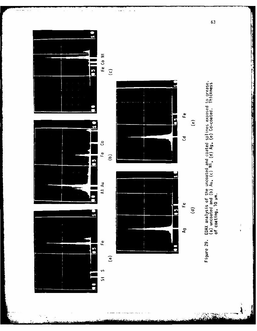
29 EDAX analysis of the uncoated and coated 63splines exposed to grease. (a) uncoatedand (b) Au, (c) Ni, (d) Ag, (e) Cd-coated.Thickness of coating, 10 pm.
- . .-.. r
10
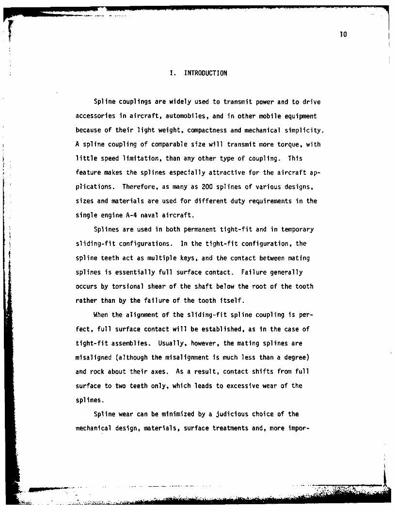
I. INTRODUCTION
Spline couplings are widely used to transmit power and to drive
accessories in aircraft, automobiles, and in other mobile equipment
because of their light weight, compactness and mechanical simplicity.
A spline coupling of comparable size will transmit more torque, with
little speed limitation, than any other type of coupling. This
feature makes the splines especially attractive for the aircraft ap-
plications. Therefore, as many as 200 splines of various designs,
sizes and materials are used for different duty requirements in the
single engine A-4 naval aircraft.
Splines are used in both permanent tight-fit and in temporary
sliding-fit configurations. In the tight-fit configuration, the
spline teeth act as multiple keys, and the contact between mating
splines is essentially full surface contact. Failure generally
occurs by torsional shear of the shaft below the root of the tooth
rather than by the failure of the tooth itself.
When the alignment of the sliding-fit spline coupling is per-
fect, full surface contact will be established, as in the case of
tight-fit assemblies. Usually, however, the mating splines are
misaligned (although the misalignment is much less than a degree)
and rock about their axes. As a result, contact shifts from full
surface to two teeth only, which leads to excessive wear of the
splines.
Spline wear can be minimized by a judicious choice of the
mechanical design, materials, surface treatments and, more impor-
p- -
10
1. INTRODUCTION
Spline couplings are widely used to transmit power and to drive
accessories in aircraft, automobiles, and in other mobile equipment
because of their light weight, compactness and mechanical simplicity.
A spline coupling of comparable size will transmit more torque, with
little speed limitation, than any other type of coupling. This
feature makes the splines especially attractive for the aircraft ap-
plications. Therefore, as many as 200 splines of various designs,
sizes and materials are used for different duty requirements in the
single engine A-4 naval aircraft.
Splines are used in both permanent tight-fit and in temporary
sliding-fit configurations. In the tight-fit configuration, the
spline teeth act as multiple keys, and the contact between mating
splines is essentially full surface contact. Failure generally
occurs by torsional shear of the shaft below the root of the tooth
rather than by the failure of the tooth itself.
When the alignment of the sliding-fit spline coupling is per-
fect, full surface contact will be established, as in the case of
tight-fit assemblies. Usually, however, the mating splines are
misaligned (although the misalignment is much less than a degree)
and rock about their axes. As a result, contact shifts from full
surface to two teeth only, which leads to excessive wear of the
splines.
Spline wear can be minimized by a judicious choice of the
mechanical design, materials, surface treatments and, more impor-
11
tantly, by lubrication. Depending on the application, lubrication may
be provided by liquid lubricants, grease, or even by solid films.
Previously, Ku and his associates at the Southwest Research In-
stitute (SwRI) have extensively studied the effects of parameters such
as misalignment, materials and lubricants on spline wear.(1 - ) Those
studies led to the formulation of certain greases to minimize spline
wear. Also, it was observed that certain hard coatings and plastic
films were ineffective in reducing wear. However, the mechanism by
which splines wear remained uninvestigated. Clearly, it would be im-
possible to optimize the spline materials and operating conditions
without the knowledge of the basic mechanism of wear.
During the course of the research at MIT on the delamination wear
of metals it was demonstrated that soft metallic coatings such as Au,
Ni, Ag and Cd increase the sliding wear resistance of metals by several
orders of magnitude when the thickness of the soft metal is controlled.
Effects of several parameters such as the coating thickness, substrate
roughness and hardness have been comprehensively studied. It was pro-
posed, therefore, that soft coatings would prevent the wear of
splines.
Accordingly, this study is aimed at investigating the basic
mechanism of spline wear and exploring whether the soft metallic
coatings could be used to enhance spline life. Scanning electron
microscopy and ferrography were extensively used to investigate the
basic wear mechanism. The results showed that the mechanism of spline
wear was the same as that postulated by the delamination theory of wear.
It was also found that spline wear could be minimized by the applica-
tion of soft metallic coatings.
Vt -
.

12
II. EXPERIMENTAL PROCEDUREStI
4 A. Spline Materials and Design
AISI 4130 steel splines through-hardened to 28-32 Rc (inner spline)
and 33-37 Rc (outer spline) were used for this investigation. These
splines are extensively used for a variety of aircraft applications.
The tooth had involute design and it was not crowned. The surface
roughness of the splines was 1.6 um (rms) and had a circular clearance
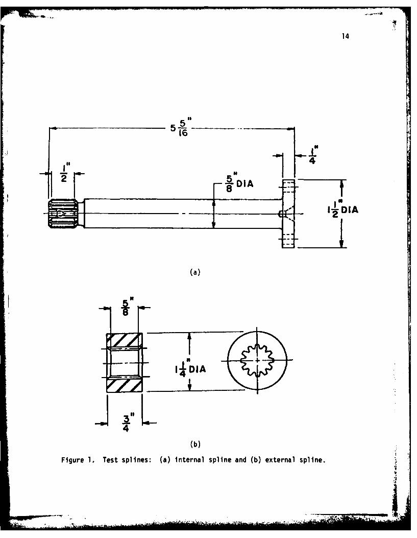
of 0.25 mm. Other design details are given in Table I and the test
specimen is shown in Figure 1. The microstructure of the hardened
splines close to the contact area is shown in Figure 2.
B. Coatings
Five coatings (Au, Ni, Ag, Cd and Cu) were used to study the
4 Ieffect of the type of coating and thickness. These coatings were
chosen on the basis of an earlier study at MIT on the effect of soft
meta1llc coatings in wear.(8 '9) Machined splines were cleaned in
boiling trichloroethylene and were plated without any preparation.
Except the Ni coating, all other coatings were applied over a flash of
Ni on the splines to improve bonding. All coatings were applied by
the standard commercial electroplating procedures using standard baths.
Coatings of three thicknesses 0.1, 1.0 and 10.0 um were used. (In
the case of gold coating 20.0 um coating was also used.) As it was
not possible to use thicker coatings without changing the spline geo-
metry, very thick coatings were not used.
-- .- . . .. * .- *4* t - .. 4 .
13
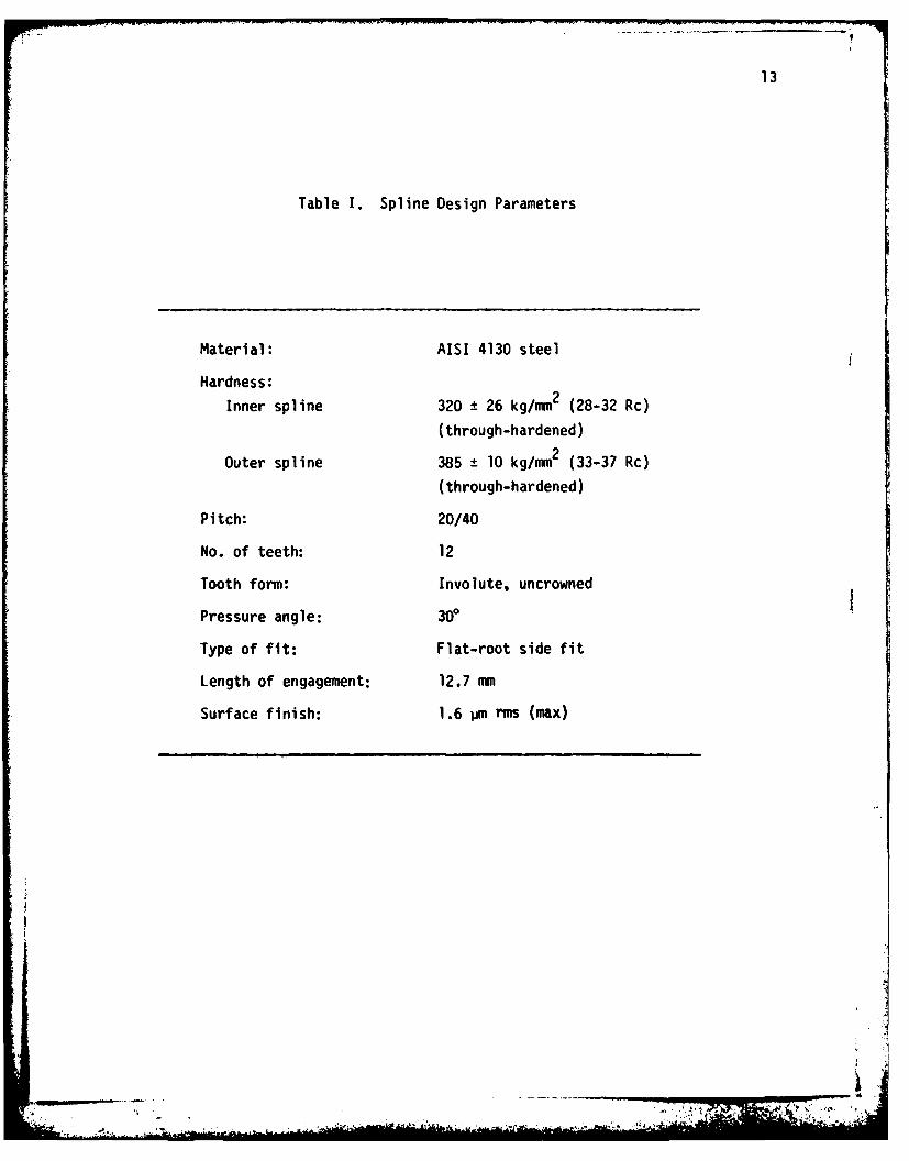
Table I. Spline Design Parameters
Material: AISI 4130 steel
Hardness:
Inner spline 320 ± 26 kg/mm2 (28-32 Rc)
(through-hardened)
Outer spline 385 ± 10 kg/mm2 (33-37 Rc)
(through-hardened)
Pitch: 20/40
No. of teeth: 12
Tooth form: Involute, uncrowned
Pressure angle: 300
Type of fit: Flat-root side fit
Length of engagement: 12.7 mm
Surface finish: 1.6 pm rms (max)
-.4 .... - " "
14
55
4
IIP,
(a)
I*LDIA 4
(b)
Figure 1. Test splines: (a) internal spline and (b) external spline.

15
"0 'A i.
- 1* teV 4 .
44,
20. P.e
Figure~~ ~ ~ ~ ~ ~ 2. Mirsrcueo-adne pie:()itra
spin and (b xena pie

16
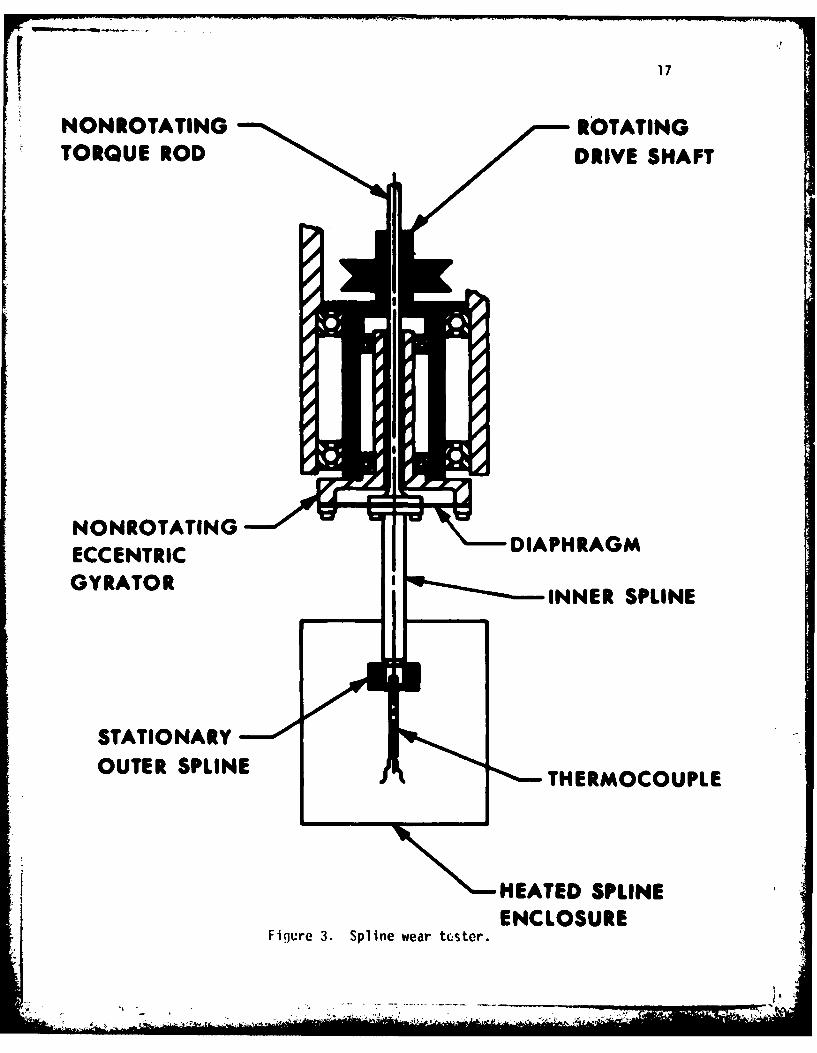
C. Apparatus and Test Procedures
The apparatus (Figure 3) used was a spline wear tester designed
and fabricated by the Southwest Research Institute, San Antonio,
Texas. It was described in greater detail in the publications of
Ku and his colleagues.(I-7) Briefly, the construction of the appara-
tus was such that the inner spline gyrated (without rotation) inside
the fixed outer spline. This motion simulates the oscillatory motion
of a pair of misaligned splines. Although the amount of misalignment
could be varied, it was kept at 0.006 rad (1.34 deg) in this study.
A torque was applied to the spline assembly through a deadweight
system. As the spline teeth wore during the experiment, the dead-
weight moved gradually downward. This downward motion was recorded
by an LVDT and the amount of wear was calculated from the LVDT
readings.
All the tests were carried out at a speed of 4400 revolutions
per minute and with grease. Some unlubricated tests were also con-
ducted to observe the behavior of the splines without any grease.
Table II lists the test conditions.
D. Friction Tests
To determine the friction coefficients between the Inner and outer
splines, splines coated with 10 jim Au, Ni, Ag and Cd were tested.
The machine used was a multifunctional testing machine, which is an
adaptation of a lathe. A special tailstock incorporates a quill
which is instrumented with strain gages to measure both thrust and
torque and which can be controlled to move very precisely in the
17
NONROTATING ROTATING
TORQUE ROD DRIVE SHAFT
NONROTATING Z DAHRGECCENTRICDAHRGGYRATOR *' INRSLE
STATIONARYOUTER SPLINE THERMOCOUPLE
HEATED SPLINEENCLOSURE
Figure 3. Spline wear tcster.
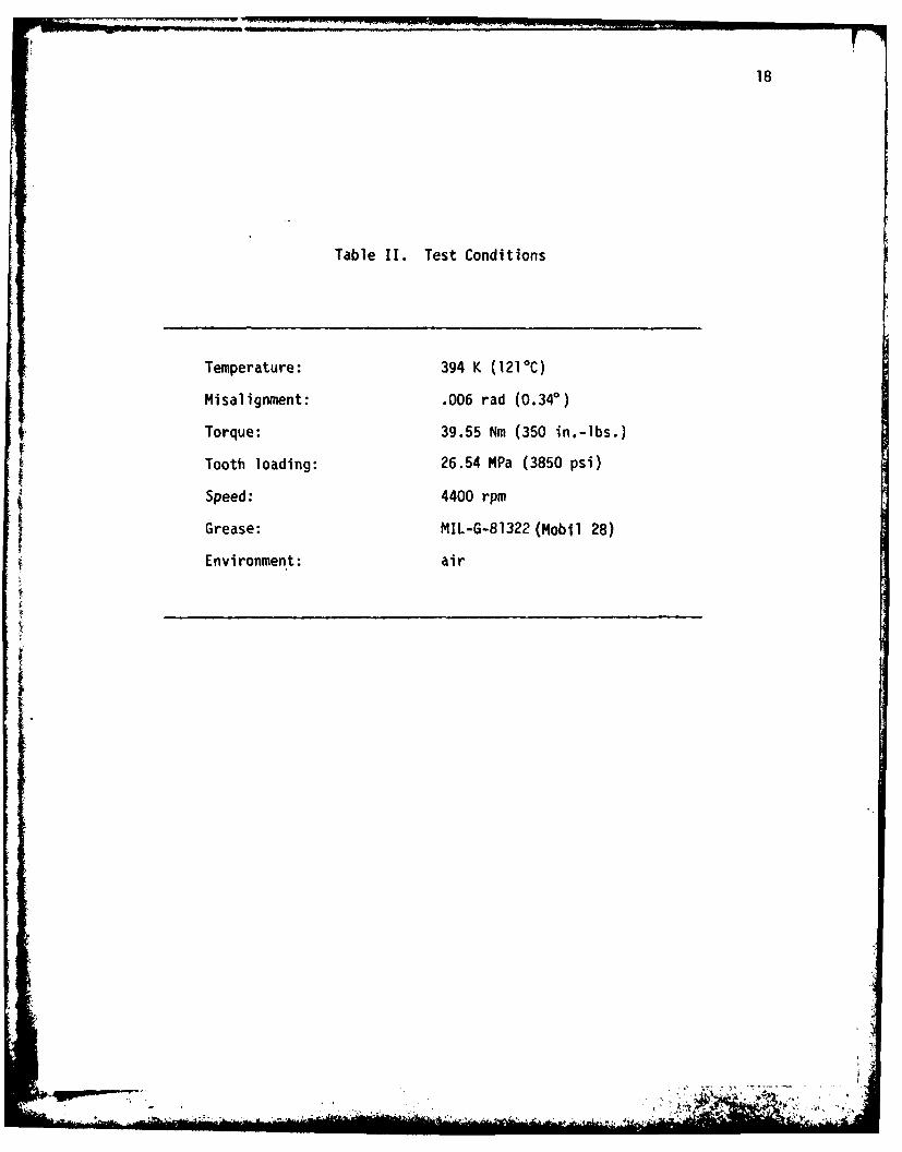
18
Table II. Test Conditions
Temperature: 394 K (121 0C)
Misalignment: .006 rad (0.340)
4Torque: 39.55 Nm (350 in.-lbs.)
Tooth loading: 26.54 MPa (3850 psi)
Speed: 4400 rpm
Grease: MIL-G-81322 (Mobil 28)
Environment: air
I qpw

19
axial direction. The headstock also has provision for precise, slow-
speed rotation for torsion tests.
Outer splines were chucked and the inner splines were attached
to the tailstock. While applying a torque of slightly greater than
39.55 Nm (350 in.-lbs.), the inner spline was pulled out slowly and
both thrust and torque were recorded simultaneously. From these
measurements, the coefficients of friction were calculated. Splines
were tested both with and without grease. During the tests it was
very hard to detect whether the coatings were peeling off. However,
the cadmium coating seemed to have the poorest bonding.
E. Optical Microscopy
Some of the untested and tested splines were photographed in
an optical microscope to observe the qualitative aspects of the
unworn and worn splines. For this, the splines were cleaned in
an ultrasonic bath of trichloroethylene and dried by a jet of warm
air and photographed directly.
F. Scanning Electron Microscopy
The surfaces and subsurfaces of machined and worn splines were
observed in a scanning electron microscope (SEM) after cleaning in
an ultrasonic bath. For surface observations no preparation was
necessary. For subsurface observation, the specimens were plated
with 50 Pm electroless nickel and were cut approximately parallel
to the spline axis by a diamond cut off wheel at low speed. Then
they were polished by the usual metallographic polishing techniques.
_7
20
After etching with nital, the specimens were coated with gold in a
vacuum evaporator and were observed in the SEM.
G. Ferrography
For ferrographic analysis the splines were prepared by first
washing them in 10 ml of 50 percent MIL-L-23699 jet oil and 50 per-
cent hexane in an ultrasonic bath. Toothpicks were used to pry
grease loose from the spline teeth. The grease was very dry and
adhered well to the spline, but ultrasonic agitation broke up the
dried grease freeing the wear particles. The resulting wash was
then diluted by as much as 2000 : 1 to obtain ferrograms with the
right particle density for comfortable microscopic observation.
In the case of splines tested in the induction period the dilution
was only 10 : 1. The grease used for the tests was also analyzed
by the ferrography technique.

21
III. RESULTS
A. Wear Tests
The results of lubricated tests are shown in Figures 4-7 where
the total wear (wear of internal ana external splines) is plotted
as a function of the test time. In the interest of clarity only the
average values are shown in the figures. For any one condition, three
to four tests have been conducted. Large scatter in the data was ob-
served and the calculated standard deviation was sometimes as much
as 10 percent of the mean value. Despite this large scatter, the
trends given by these figures are fairly accurate. In the case of
copper coatings, only one test was conducted for each coating thick-
ness. As the results were similar to those shown in Figures 4-7,
these results will not be discussed further. It is clear from Fig-
ures 4-7 that there is a period of negligible, or "mild", wear called
the induction period. After the induction period, the splines start
wearing faster and the amount of wear is approximately proportional
to the test time.
The induction period as a function of the coating thickness is
shown in Figure 8. It is easily seen from the figure that in the
case of Au coated splines the induction period is a strong function
of the coating thickness. Nickel coated splines exhibit a maximum
induction period for a coating thickness of about 1.0 um. Ag and Cd
coated splines did not exhibit any higher induction periods than the
uncoated splines. In fact, splines coated with 10 pm Ag exhibited
induction periods smaller than the uncoated splines.
1.-

22
0 00 -D '- N - C D 'J \ 0
0 rF)(0 ,IZv EE 0 C
0 _
o o -(00
0
( 0) 4-
0- VC,
o 00C~CL
LLI.
00
00
I I I I I I00u~W0) O fO
C~N--0
WW '~3M
-. 4 .No

23
00
00(
0 ZO 3.zi. 00
0 0dN j
0 - 0
0 -* 4--
000-ON
4-
00
0
-0 L
WW 'd813M
24
0 U
I I I I I I
0~
(D(.0
z 4-
0)0< E E Ec00 00 0
L)) uL
X 0 *c0- 0- -
LLiI
0U)U
) I-JC"'
04-0
0
C~ c
-00-
(101!0 -' - 0 - 1 .... ' -

25
0 U!' \J0 0 D TC
0(0 OD
00
E
0 4Joz0
C-4-
:L:L , .00 0
0) -
00
- w
L
LoA
0 d d do d d 0Uu Lu'8VN

26
(0 ~~Salo,'o
o 0 0 0 0 0 0I I I ! I I I
I/I0 0
-. 5-
cLJ
-0 .2
0~ C) O
0u0
- 0
0 0 0 0 0 0 0 0 0000 0 0 000 w wO q N 0 wl D 0 wO wD q Nrn IN N N\JJ N.
4 '00183d NOI1onfGNI

27
The wear rate after the induction period is plotted as a function
of the coating thickness for all the coatings in Figure 9. Splines
coated with Au, Ni and Cd exhibited about the same wear rate which
was independent of coating thickness. Silver coated splines exhibited
generplly higher wear rates and the wear rate increases with the coat-
ing thickness. Considering the scatter in the data, however, it may
be concluded that the wear rate of the splines after the induction
period is essentially independent of the type and initial thickness
of the coatings.
B. Friction Tests
The friction coefficients of uncoated and coated splines with
and without grease are shown in Table III. These tests were conducted
at room temperature and for the same torque that was used in the spline
wear tests.
From the table it can be seen that the friction coefficient Is
reduced substantially by the grease. Gold coated splines exhibited
the highest friction coefficient, both lubricated and unlubricated.
Cadmium coated splines exhibited the lowest friction coefficients.
Surprisingly, the gold coated spline, despite the high friction co-
efficient, has also the largest induction period.
Although the values listed in Table III give some approximate
idea about the friction coefficients, to interpret the wear results
meaningfully it is necessary to measure the friction coefficient con-
t inuously.

28
0 1I3 A:)/w71
C'i Ni a0 C5
I I I I
u' )0-0
Lii
Uu ~ ~ ~ ~ 9 wJV 8

29
Table III. Friction Coefficients of Uncoated and Coated Splines
Friction Coefficient**Type of Coating*
Without grease With grease
No coating 0.41 0.23
Au 0.86 0.48
Ni 0.62 0.20
Ag 0.81 0.14
Cd 0.33 0.09
* Both internal and external splines were coated. The thicknessof the coating was 10 pm.
** Average of at least three measurements.

30
C. Optical Microscopic Observations
Optical micrographs of untested and tested internal splines with
and without coating are shown in Figure 10. It appears that the sur-
faces of the splines after 0.4 mm wear are the same in both cases.
Observations of external splines also showed a similar trend. The
teeth are worn on only one side as the torque was applied only in one
direction throughout the test. It can also be seen from the figure
that the teeth are worn symmetrically about the midpoint. The coat-
ings were completely removed in all cases.
Optical micrographs of splines tested within the induction per-
iod are shown in Figure 11. It is clear from these figures that the
contact was established only at a few areas and that the entire
spline tooth did not wear. Again, similar trends were observed
in the external splines. Although there was some wear, the coatings
remained more or less intact.
D. Scanning Electron Micrographs
To examine the basic mechanism of wear in the induction and
post-induction periods, extensive scanning electron microscopy
work was carried out on both internal and external splines. Figures
12-15 show the surfaces of both internal and external splines coated
with Au, Ni, Ag and Cd with 0.1, 1.0, and 10 pm thick coatings and
tested to a total wear of about 0.4 mm. These figures clearly show
that the surface becomes very rough and that it is covered with loose
debris and cracks. The micrographs also indicate that the surfaces
have essentially metallic characteristics. (The SEM micrographs were
_______ ______ ___ _-_ __ _ .... . .._ I

31
41
0 ((0 u
-
r~(A0
m~ 4-)
'In
C
4- 3
0
toCS- 0--olow 0~S J 4-
4-JCL
to a)
CD-
00
, L
4'iZJ
32
(.CD
C)0-J
c
cu -o= C)
o y
c~ 0
o) -
~~i.+ j~cn
(A 0to Q)_
33
c C
30 C0*
lift-
*0
JAEv.0-'
do 0
4-2
0 0 4(4J
W V4J
ed ~0
b.. -4
Idl., 44-,--
- E
. . .. .. .. .. .. .. ...........

plow34
4
Ce
-CE
45W0 wc1- E=~
tt
((
4-C
to
3:4)
4r 41
116,u (U

35
4J0 C%
.- M
tin~
S- )
x -
06
4J0
4-) t
* 03S.
* ~- 0
* -10
0 3
4-~ 03030
V *0 IV
- p C.

36
CA
f 0
-0 C
O4-' 1-- 4J
'C
toS~-.
C
I-0J0 -
o
o
0E0
4-
4- 4)-
IrC)

37
taken without any metallic coating on the tested splines.) Although
occasionally some plowing grooves were seen, large scale abrasion
tracks were not observed. Further, the direction of the cracks is
approximately normal to the axis of the spline.
An important characteristic of these micrographs is that the
surface topography after 0.4 mm wear is entirely different from the
type and initial thickness of the coating. It is perhaps not sur-
prising because once the coating is removed, the substrate gets ex-
posed, and the wear of the splines is essentially controlled by the
subsurface spline material and not by the coated material.
Micrographs of splines tested only in the induction period are
shown in Figure 16. In this case most of the tooth area remained
undisturbed except in certain patches where the wear was severe. The
micrographs clearly show that the worn area looks similar to the
case when the splines were tested to 0.4 mm.
Scanning electron micrographs of the surfaces of the gold splines
tested only in the induction period are shown in Figure 17. In con-
trast to the surfaces of splines worn to 0.4 mm, these surfaces do
not show any cracks. The gold coated splines exhibit only plowing
grooves and it appears that large scale plastic deformation took place
in the gold coating.
As the surface features indicated that there were no essential
differences between splines coated with coatings of various thick-
nesses, subsurfaces observations were carried out on splines coated
with 10 um Au, Ni, Ag and Cd only. Figures 18-21 indicate that
large subsurface deformation took place as a result of the fretting
-. -4

38
C) 4-3
44
(A -1a) a)
.C-4-Cfl
S-a
a)-
.-.
-4..-
j4-----
u A -
_-a CL
U .C
or- -
a) to
L--o0

-I
P ,.-
39
i.,=.
20-pe
Fiur 174ufc fgl-otd(1 m pietse nyi
thanuto eid(0 ) a nenlsln n
(b)exeralkplne
Jt,_;

40
TI
4-)
C
~LL.

41
-4-
L
a)
~.:~t* t-
4M~

42
4-
C
4-). 4-)0 Q)
L o
EO
0-
o
fa)
SC
Ale
II

43
IL-
4J
4J
43
0
4-.4-
10.
Lfl
44
process in both internal and external splines. However, it was dif-
ficult to observe cracks in these micrographs.
Subsurface observations were also carried out on splines tested
only in the induction period. In the case of gold-coated splines, it
can be clearly seen (Figure 22) that the subsurface did not deform
at all and that the deformation was confined to the coating only. Al-
though subsurfaces of splines coated with other metals were not ob-
served, it could be concluded based on the above observations that in
the induction period, subsurface deformation will be either too low or
it would be confined to the coating only.
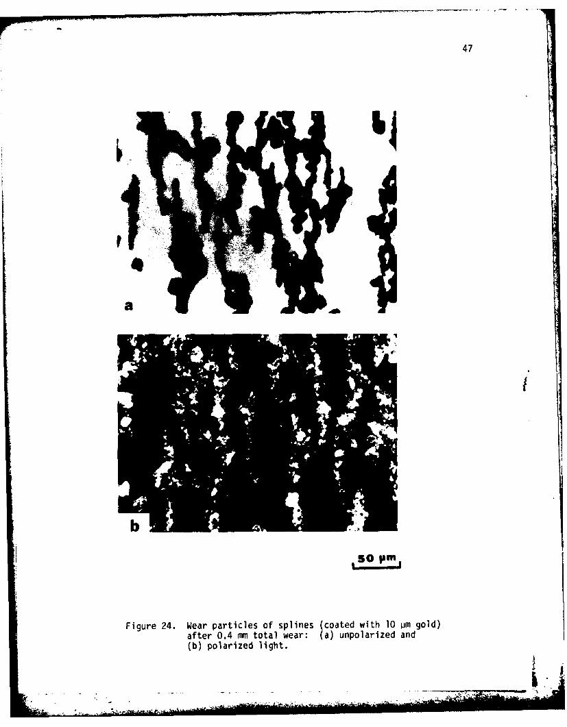
Figure 23 shows the wear particles at the entry region of the
ferrogram of the splines tested to 0.4 mm wear. These splines were
coated with 10 jim thick Au, Ni, Ag and Cd. The wear particles have
a range of sizes and are essentially metallic in character, although
the surface is a bit oxidized. To check whether the surface is oxi-
dized, micrographs were taken with polarized light. Figure 24 indeed
shows that the surface of the particle is oxidized. (If the particle
is completely oxidized it would be difficult to deposit the nonmag-
netic, or weakly magnetic, oxides on the ferrogram.)
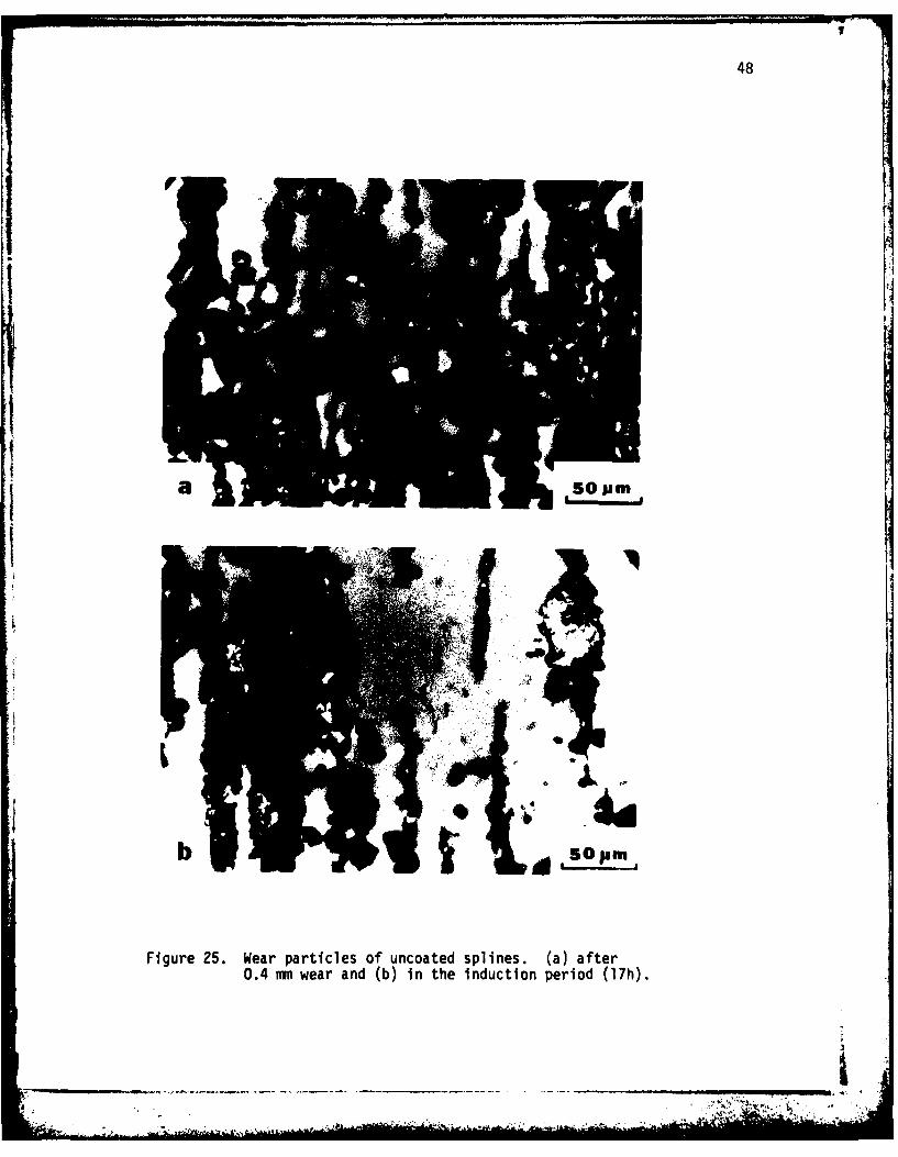
Wear particles of splines tested only in the induction period
are shown in Figure 25. It is interesting to note that the size and
shape of the wear particles is exactly the same as that of the wear
particles collected after 0.4 mm wear. However, the concentration
of the wear particles was about 100 times smaller than that of the
post-induction period. Figure 26 shows the wear particles of gold
coated spline tested only in the induction period. The wear particles
_ ___________
1) 45
4J
al0 c
41
V)
CL
LA
0 S-
COi
C
* SA .

46
El01
-)
4 E
a) 0
LA 4-'LA
ro'4CL,
00i
47
V~I
a!
SOpm,
Figure 24. Wear particles of splines (coated with 10 pim gold)after 0.4 mm total wear: (a) unpolarized and(b) polarized light.
-I _ / ..... .
48
IS P
Figure 25. Wear particles of uncoated splines. (a) after0.4 num wear and (b) in the induction period (17h).
.... . -

49
501Pm
Figure 26. Wear particles of splines coated with 10 um goldand tested in the induction period (209h).(a) white light and (b) bichromatic light.
50
are thin flakes.
Ferrograms of the grease (Figure 27) indicate that the grease
contains fibers, ferrous debris, etc., although the concentration
was very low.
Ir
i ''
'II

51'
Figure 27. Ferrograms of the grease used in the splinetests. (a) entry and (b) at 27 mmn on theferrogram.
IV. DISCUSSION
From Figures 4-7 it is clear that the wear rate of splines lub-
ricated with grease changes by orders of magnitude with time. In
the post-induction period, the wear rates are very high (Figures 4-7), j
the surfaces of the specimens become rough (Figures 10, 12-15), and
large subsurface deformation takes place (Figures 18-21). By contrast,
in the induction period the wear rate is much smaller (Figures 4-7),
the surfaces are largely unaffected (Figure 11) and the subsurface is
also unaffected (Figure 22). These results suggest two regimes, if not
mechanisms, of wear. Accordingly, the following discussion is divided
into two sections; (A) Post-induction period and (B) Induction period.
In addition, the role of coatings is also discussed.
A. Post-Induction Period
Although the rate of wear after the induction period is very
high and perhaps objectionable from the stand point of practical ap-
plications, an understanding of the basic mechanism in this regime
is very much needed for selecting spline materials, operating con-
ditions and lubricating procedures. An important point to be noted
here is that both coated and uncoated splines wear at the same rate,
regardless of the initial thickness and type of coating. The post-
induction period wear rate is in turn the same as that shown by
unlubricated splines as shown in Figure 28. Further, the surface
{i observations indicate that the coating is completely removed, and
subsurface features and wear particles clearly show that the dif-

53
0 Ul
0 w N o0 w w 0" w 0oTTTT II I I 1 0°00
ou N00 c
IC) co 1'4 J+J
00
o Cu
-.0 0
0 r =4.)
0 o - .C 4J
E E to fa 4
0L 0
4J
°- : o0
10~~ 4 C;4U
0D a 0 9 4
UI UM 4J
0 T
N - r-.0 .
0C- 0
0 1
0A0
0 0 00 0 t 0 EU-0
o o oo o oo o
WW '8V3M

54
ferences among the splines coated with different soft metals are only
marginal. It is clear therefore, that the onset of "severe" wear is
marked by the complete removal of both the coatings and the grease.
Since the mode of displacement is oscillatory (with a small am-
plitude), the mode of wear, by definition, is fretting. However,
since various mechanisms of fretting wear have been proposed in the
past, a brief description of the theories is given below.
The theories of fretting wear can be organized into four groups.
The first mechanism of fretting assumes oxidation of the surface
metal and its subsequent removal during the oscillatory motion.(1518)
The earliest theories( 5'16 )in this category assumed that material
was removed from the fretted surface atom by atom and then these atoms
combined with the oxygen in the environment to yield metallic oxide.
Later theories( 17'18 )assumed that the oxide is formed on the surface
of fretted metal (because of temperature rise and plastic deformation)
and then it is subsequently scraped off, again by the mechanical action.
Since fretting readily takes place between nonmetals and noble metals,
oxidation is not a requirement of fretting.
The second mechanism of wear in fretting assumes that materialremoval takes place not by oxidation but by adhesion.g")In a re-
cent investigation (14 ) it was observed that the wear coefficients
obtained in fretting are the same as that in uniaxial sliding, i.e.,
by adhesion.
A third mechanism proposed to explain the fretting wear of metals
is based on abrasion.(2 2 "25 )According to this theory, metallic par-
ticles will be removed initially from the fretted surface. Subse-
__ _ _ _ _ _ _ _ _ _
-. _ - .... -
55
quently, they oxidize and contribute to the abrasion of the surfaces
from which they are formed.
More recently, Suh(26)suggested that the early stage of fretting
wear is caused by the wear mechanism postulated in the delamination
theory of wear!0)According to the delamination theory, wear takes
place by subsurface deformation, crack nucleation and crack propaga-
tion processes. Once the wear particles are generated, they may un-
dergo oxidation and act as abrasive particles between the fretted
surfaces, accelerating the wear process further, but the critical
stage in fretting is the delamination process.
Undoubtedly, all the above mechanisms operate simultaneously
during fretting. The important point to be recognized here is to
identify the dominant mechanism, i.e., the mechanism that contributes
the largest amount to the total wear. Recent experimental observa-
tions (27"2glindicate that the delamination wear takes place during
the entire fretting process, not just at the beginning.
According to the delamination theory of wear,(10)when two
sliding surfaces come into contact, normal and tanqential loads are
transmitted through the contact points by adhesion and plowing.
The surface traction exerted by the harder asperities on the softer
surface induces plastic shear deformation which accumulates with
repeated loading. As the subsurface deformation continues, cracks
are nucleated below the surface. Crack nucleation very near the
surface is not favoured because of the triaxial state of highly
compressive stresses which exists just below the contact. Once
cracks are present (owing either to crack nucleation during wear
56
or to preexisting voids) further loading and deformation causes
cracks to extend and to propagate joining the neighboring ones. The
cracks propagate parallel to the surface at a depth governed by the
material properties and the coefficient of friction. When cracks can-
not propagate, because of either limited deformation or an extremely
small tangential traction at the asperity contact (i.e., low friction
coefficient), crack nucleation controls the wear rate. When the
cracks finally shear to the surface (at certain weak spots) long, thin
wear sheets delaminate. The thickness of the wear sheet is determined
by the location of the fastest growing crack which in turn is con-
trolled by the normal and tangential tractions at the asperity con-
tact.
It is interesting to note that Figures 12-15 and 18-21 indeed
show that the surface features, subsurfaces and wear particles are con-
sistent with the predictions of the delamination theory. The surfaces
of worn splines show that the surface becomes extremely rough due to
wear particle removal in the form of large chunks of metal rather than
by the asperity removal mechanism as suggested in the adhesion theory
of wear. The subsurface micrographs indicate that large subsurface
deformation took place.
Two observations need further elaboration. First, it was dif-
ficult to observe the subsurface cracks in both internal and external
splines, although numerous surface cracks have been observed. Second,
the wear particles are not thin long sheets; the particles are rather
chunky. These observations indicate that because of small oscillating
displacement crack nucleation may be the controlling mechanism, rather
. K~ >2 .

I 57
than the crack propagation being the rate controlling mechanism. When
crack nucleation is the rate controlling mechanism, the cracks do not
grow too far before a wear particle is removed. In the case of uni-
axial sliding wear of ductile metals, thin long wear sheets are ob-
served indicating that crack propagation is the rate controlling pro-
cess.
The operation of the delamination mechanism is also observed in
the case of splines coated with 10 Um gold and tested only in the in-
duction period (Figures 17, 22, 26). Large scale surface and sub-
surface deformation and long thin wear particles clearly indicate
that the delamination mechanism is responsible for wear in the in-
duction period in the case of gold coated splines.
B. Induction Period
A major reason for low wear rates in the induction period is
the effectiveness of the grease. When the grease is fresh, the fric-
tion coefficient is low (see Table III), and therefore the traction
at the asperity contact will also be low. Because of the low friction
coefficients, the wear rates are also expected to be low. It has been
shown in the past that wear rates increase almost exponentially with
friction coefficients both in the case of uniaxial sliding (12' 13)
and in fretting!14)
The fact that the grease was effective in reducing the wear rate
could be further explained as follows. Figure 28 shows the wear rates
of the splines, both uncoated and coated with gold, without grease.
Interestingly, the wear rates of both splines are about the same.

58
This wear rate, in turn, is the same as the post-induction wear rates
of both coated and uncoated splines lubricated with grease. Moreover,
it was observed that the grease samples collected in the induction
period were wet, whereas after 0.4 mm wear, they were very dry and
the wear particles were collected as powder. Further confirmation of
this hypothesis can be obtained by examination of previous data( -7)
where different lubricants including jet fuels (which are inefficient
lubricants) give high wear rates with no induction period at all.
Unfortunately, the SwRi setup is not equipped to measure the
friction coefficients. It would be interesting to see in the future,
whether the onset of the induction period coincides with the loss of
lubricating property of the grease and the concomitant increase in
friction.
Microscopic observations of the surface (Figure 17), subsurface
(Figure 22) and wear particles (Figure 25) of the uncoated and gold
coated splines again show that the wear in the induction period is
by the delamination mechanism. However, as can be seen from the
optical micrographs (Figure 11), the entire tooth does not wear at
the same time. Instead, the damage is confined only to certain areas.
C. Effect of Soft Coatings on Spline Wear
It is clear from the results that splines coated with Ni, Ag and
Cd did not perform any better than the uncoated splines. To some
extent this result is surprising because in the MIT study on soft
coatings it was found that Au, Ni, Ag and Cd reduce wear by several
orders of magnitude in an argon atmosphere even without lubrication 8,9 )

59
In that study the following conditions were identified: (a) for
major wear reduction the coating material must be softer than the
substrate material (the hardness of the substrate should be at least
four times that of the coating), (b) the optimum thickness of soft
coating is in general less than 1 Um for steels coated with Au, Ni,
Ag and Cd, (c) gold is effective in air and inert atmosphere, whereas
NI, Ag and Cd were effective only in inert atmosphere, (d) the surface
roughness of the substrate and the coating/substrate bond strength
are two important factors for the wear resistance of soft metallic
coatings.
When these conditions were satisfied it was observed that the
wear resistance could be increased at least by a factor of 500. Since
the induction period is increased by only a factor of four (which ap-
proximately means that the wear resistance is also increased by a
factor of four) and since this increase in wear resistance was ob-
served only with grease, a discussion of the role of coatings in terms
of the criteria listed above is in order.
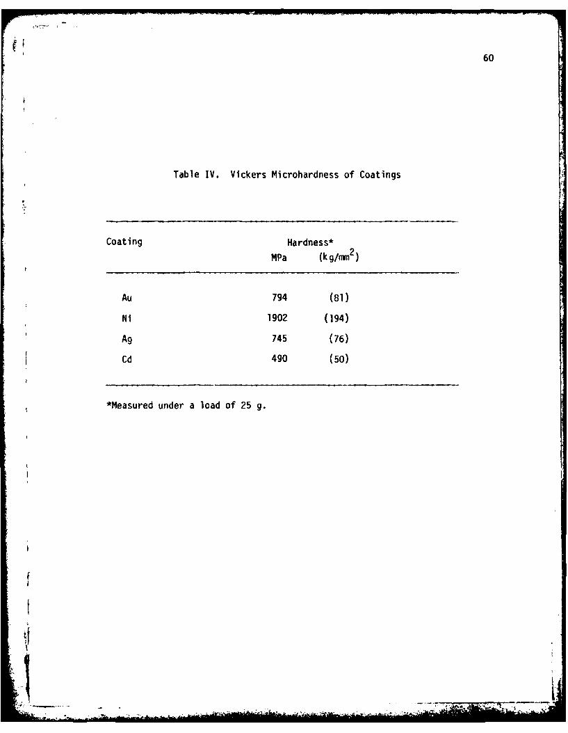
The primary requirement the coatings have to satisfy is that
they should be softer than the substrate. The electroplated coat-
ings except Ni (see Table IV) are much softer than the hardened AISI
4130 steel substrate. The failure of Ni to enhance the wear resistance
can thus be attributed to the hardness mismatch. That is, when the
coating is very hard, the delamination wear takes place in the coat-
ing itself and therefore it fails to protect the substrate. However,
since Ag and Cd also failed to increase the wear resistance of the
splines, it is necessary to look into the other criteria also.
60
Table IV. Vickers Microhardness of Coatings
Coating Hardness*
MPa (kg/mmi2)
Au 794 (81)
Ni 1902 (194)
Ag 745 (76)
Cd 490 (50)
*Measured under a load of 25 g.

61
For the coating to be effective, the thickness of the soft coating
should be in the range 0.1 - 1.0 um. The thickness values used in this
investigation are in that range, but still the coatings failed to pro-
tect the subsurface, i.e., the coated specimen showed the same induc-
tion period as the uncoated splines except in the case of gold coating.
Another requirement for enhancing the wear resistance by the ap-
plication of soft coatings is that they should be inert. When Ni, Ag
and Cd coated specimens were tested in air in the MIT study, (8'9 ) they
failed to increase the life of the specimens. On the other hand,
gold performed well in both the inert atmosphere and the oxidizing at-
mosphere. Since only gold increased the induction period of the splines,
it may be suspected that the coatings were lost by chemical reaction
with grease.
To check whether the coatings reacted with the grease, energy
dispersive X-ray analysis (EDAX) was carried out to identify the com-
position of the coatings exposed to grease. This was done on the
side of the tooth that was not under load but was exposed to the grease
for the same time as that required for 0.4 nmn wear. The surfaces were
cleaned in trichloroethylene, dried and observed in the SEM that was
equipped with X-ray analyzer. Unfortunately, it was not possible to
obtain the composition of the grease. (The Mobil Company declined
to furnish the composition of the grease.) Clearly, it would be dif-
ficult to identify the compounds formed by the coatings due to reaction
with the grease unless the approximate composition of the grease is
known. It was assumed, therefore, that the grease contains P, S and
Cl (most additives for EP lubricants contain these elements) and EDAX
i
62
analysis was carried out to identify these elements. Figure 29 shows
the X-ray intensities of both coated and uncoated splines. According
to these results it is clear that P, S and Cl were not on the sur-
faces of the splines (both coated and uncoated) which indicates that
the coatings did not react with the grease and that the failure of
the coatings to enhance the induction period was not due to the chem-
ical reaction between the coatings and the constituents of the grease.
That leaves the surface roughness and bonding requirments. To
check whether the surface roughness affects the induction period, a
set of splines (inner and outer) was polished with 0.25 um diamond
lapping compound and plated with 10 um gold and tested with grease.
The induction period was, within the experimental scatter, no dif-
ferent from that shown by the splines that were plated directly with-
out polishing.
It appears, therefore, that the coating/substrate bonding is
the most important factor. It is well known in the coating area that
good adhesion is a requirement for satisfactory performance of soft
metallic coatings. Although all the splines were plated with
a flash of Ni before electroplating with the soft metals, it appears
that Ag and Cd (and Cu) did not exhibit good adhesion. Unfortunately,
it is difficult to devise a meaningful test for the bond strength
of these coatings because the test results depend not only on the
inherent strength of the coatings, but also on a variety of test var-
iables (e.g., geometry, load, speed, etc.). In any case, since the
loading conditions in fretting are much different from the standard
tests, it is difficult to relate the results of standard tests to
*
63
sod)
-S be.
x oQ) 0
0 a
-Um0
u 4Jw
0*'
0)-W-
L- 0J -
VIV

64
the induction period meaningfully. Nevertheless, by a process of
elimination it is shown here conclusively that the good bonding be-
tween gold and the substrate is responsible for the increases induc-
tion period in the case of gold coated splines.
Even so, the gold coated spline did not increase the induction
period dramatically (contrary to the observation of uniaxial sliding).
Unlike the case of uniaxial sliding, the loads and speeds used in the
spline tester were much higher and the relative displacement was much
smaller. The concentration of load and the geometric constraint amp-
lified the stresses in the substrate (moreso than in the sliding case)
so that failure occurred at the loaded area creating wear particles.
Unlike the sliding case the same spot is subjected to continuous
cyclic loading.
Nevertheless, it is shown in this study that spline life can be
increased by coating with soft metals. If bonding between the substrate
and the coating can be improved, it is expected that splines coated with
soft metals like silver and cadmium will have higher induction periods.
Cadmium appears to be the best choice since the friction coefficients
exhibited by cadmium coated splines are expected to give substantially
high induction periods.
It has been shown by many investigators in the past that ion
plating and sputtering give coatings that adhere to the substrate
tightly. Friction and wear studies on these coatings have shown that
they were far superior to electroplated coatings. It would be inter-
esting to investigate the effect of these treatments on spline wear.
Finally, the grease used in this investigation was formulated by
_L
65
a trial and error process. Although the preliminary studies have in-
dicated that the grease does not react with the coatings appreciably,
it is necessary to investigate whether the grease reacts with the coat-
ings under mechanical action. Careful study of the surfaces using
more sophisticated methods (e.g., Auger and ESCA) is needed to inves-
tigate the chemical reaction between the grease and the coatings.
Further, the ferrographic observations indicated that the grease con-
tains inorganic fillers. Time did not permit us to explore the size,
concentration and the hardness of these fillers. It is well known
that hard fillers can remove the soft coatings by abrasive wear. Al-
though it may be difficult to find fillers that do not abrade the
soft coatings, it is possible to reduce the abrasive action by choosing
fillers that are smaller than 1 Pm.

66
V. CONCLUSIONS
The following conclusions can be drawn from this study:
(a) The service life of splines can be increased by a factor of four
through the use of thin gold coatings.
(b) Of the many coatings (Au, Ni, Ag, Cd, Cu), only gold coating in-
creased the induction period; this is due to oxidation resistance of
gold and good bonding between gold and the substrate.
(c) Unlubricated splines, and splines lubricated with grease wear
by the subsurface deformation, crack nucleation and crack propoga-
tion processes, i.e., by the delamination mechanism.
(d) The mechanism of wear even in the induction period is by the
delamination mechanism, although the wear rate is much smaller than
that of the post-induction period. Wear was not uniform over the
entire surface of the spline teeth.
(e) The termination of the induction period is marked by the loss
of grease or its effectiveness because of the reaction between wear
debris and grease.
(f) The induction period was increased by increasing the thickness
of the coatings up to 20 um. This may be due to more uniform dis-
tribution of the load in addition to good bonding.

67
(g) EDAX analysis of the coatings exposed to the grease did not show
any chemical reaction between the coatings and the grease.
|

68
References
(1) Valtierra, M.L., Brown, R.D. and Ku, P.M., "A Critical Survey andAnalysis of Aircraft Spline Failures," Report No. RS-574, South-west Research Institute, San Antonio, Texas, August 1971.
(2) Weatherford, W.D., Valtierra, M.L. and Ku, P.M., "ExperimentalStudy of Spline Wear and Lubrication Effects," ASLE Transactions,Vol. 8, 1966, pp. 171-178.
(3) Weatherford, W.D., Valtierra, M.L. and Ku, P.M., "Mechanisms ofWear in Misaligned Splines," Transactions ASME, Series F, Vol. 90,1968, pp. 42-48.
(4) Ku, P.M. and Valtierra, M.L., "Spline Wear-Effects of Design andLubrication," ASME Paper, No. 74-DET-84, 1974.
(5) Valtierra, M.L., Pakvis, A. and Ku, P.M., "Spline Wear in Jet FuelEnvironment," Lubrication Engineering, Vol. 31, No. 3, 1975, pp.136-142.
(6) Valtierra, M.L. and Ku, P.M., "Mitigation of Wear of InterfaceSplines," ASLE Preprint No. 77-LC-6B-1.
(7) Valtierra. M.L. and Ku, P.M., "Research on Mitigation of SplineWear by Means of Plastic Coatings," Report No. RS-539, SouthwestResearch Institute, San Antonio, Texas, January 1970.
(8) Jahanmir, S., Abrahamson, E.P., I and Suh, N.P., "The DelaminationTheory of Wear and Wear of a Composite Metal Surface," Wear, Vol. 32,1975, pp. 33-49.
(9) Jahanmir, S., Abrahamson, E.P., II and Suh, N.P., "Sliding WearResistance of Metallic Coated Surfaces, Wear, Vol. 40, 1976,pp. 75-84.
(10) Suh, N.P. and Co-workers, The Delamination Theory of Wear, Else-vier Sequoia S.A., Lausanne, 1977.
(11) Jahanmir, S. and Suh, N.P., "Surface Topography and Integrity Ef-fects on Sliding Wear," Wear, Vol. 44, 1977, pp. 87-99.
(12) Suh, N.P., Sin, H.-C., Tohkai, M. and Saka, N., "Surface Topographyand Functional Requirements for Dry Sliding Surfaces," to be pre-sented in Annals of CIRP, 1980.
(13) Rabinowicz, E., "The Dependence of the Adhesive Wear Coefficienton the Surface Energy of Adhesion," Wear of Materials 1977,Glaeser, W. A., et. al., Eds., ASME, New York, 1977, pp. 36-40.
69
(14) Stowers, I.F. and Rabinowicz, E., "The Mechanism of Fretting Wear,"ASME Paper, No. 72 - Lub - 20, 1972.
(15) Tomlinson, G.A., "The Rusting of Steel Surfaces in Contact," Pro.Roy. Soc., Ser. A, Vol. 115, 1927, pp. 472-483.
(16) Tomlinson, G.A., Thrope, P.L. and Gough, H.J., "An Investigationof Fretting Corrosion of Closely Fitting Surfaces," Proc. Inst.Mech. Engrs., Vol. 141, 1939, p. 223.
(17) Uhlig, H.H., "Mechanism.of Fretting Corrosion, Journal of AppliedMechanics, Vol. 21, 1954, pp. 401-407.
(18) Uhlig, H.H., et al., "Fundamental Investigation of Fretting Cor-rosion," NACA, Techn. Note 2039, 1953.
(19) Godfrey, 0. and Bailey, J.M., "Early States of Fretting of Copper,Iron and Steel, Lubrication Eng., Vol. 10, 1954, p. 155.
(20) Godfrey, D., "Investigation of Fretting Corrosion by MicroscopicObservation," NACA Report No. 1009, 1951.
(21) Bailey, J.M. and Godfrey, D., "Coefficient of Friction and Damageto Contact Area During the Early Stages of Fretting," Pt. 1, NACATechn. Note 3144, 1953.
(22) Waterhouse, R.B., "Fretting Corrosion," Pro. Instn. Mech. Engrs.,Vol. 169, 1955, p. 1157.
(23) Feng, I.M. and Rightmire, B.G., "An Experimental Study of Fretting,"Proc. Instn. Mech. Engrs., Vol. 170, 1956, pp. 1055-1060.
(24) Feng, I.M. and Rightmire, B.G., "The Mechanism of Fretting," Lub-rication Engineering, Vol. 9, 1953, pp. 134-136 and 158-160.
(25) Fenner, A.J., Wright, K.H.R. and Mann, J.Y., "Fretting Corrosionand Its Influence on Fatigue Failure," Int. Conf. Fatigue ofMetals, Inst. Mech. Engrs., London, 1956, p. 11.
(26) Suh, N.P., "Microstructural Effects in Wear of Metals," in Funda-mental Aspects of Structural Alloy Design, Jaffe, R.I. and ITT'x,B.A., Eds., Plenum, New York, 1977, pp. 565-595.
(27) Waterhouse, R.B. and Taylor, D.E., Wear, Vol. 29, 1974, pp, 337-344.
(28) Waterhouse, R.B., "The Effect of Environment in Wear Processesand the Mechanism of Fretting Wear," in Fundamentals of Tribology,Suh, N.P. and Saka, N., Eds., MIT Press, Cambridge, MA, 1980,FF. 567-584.
(29) Sproles, E.S., Gaul, D.J. and Duquette, D.J., "A New Interpretationof Fretting and Fretting Corrosion Damage," Ibid, pp. 585-596.
J0
70
Distribution ListNumber of Copies
Aero Material DepartmentNaval Air Development CenterWarminster, PA 18974Attn: Mr..M.J. Devine, Code 30-7 1
Air Force Aero Propulsion LaboratoryWright Patterson Air Force BaseDayton, ON 45433Attn: Mr. C. Hudson
Air Force Materials LaboratoryWright Patterson Air Force BaseDayton, OH 45433Attn: Mr. F. Brooks
Defense Documentation CenterBuilding 5Cameron StationAlexandria, VA 22314 12
National Bureau of StandardsDepartment of CommerceWashington, D.C. 20234Attn: Dr. E. Passaglia 1Attn: Dr. AW. Ruff 1
National Science FoundationEngineering Mechanics Division1800 G StreetWashington, D.C.Attn: Mr. M.S. Oja.lvo 1
Naval Air Engineering CenterGroup Support, Equipment DivisionLakehurst, NJ 08733Attn: P. Senholzi, Code 92724 1
Naval Air Systems CommandWashington, D.C. 20361Attn: B. Poppert, Code 340E I
Director Naval Research LaboratoryWashington, D.C., 20375Attn: Technical Information Division
Dr. L. Jarvis, Code 6170 6
Naval Research LaboratoryWashington, D.C. 20375Attn: R. C. Bowers, Code 6170 1
1V

71
Naval Sea Systems CommandWashington, D.C. 20362Attn: Mr. M. Hoobchack 1
Naval Ship Research and Development LaboratoryAnnapolis, MD 21402Attn: Mr. N. Glassman 1Attn: Mr. W. Smith 1
Assistant Chief for TechnologyOffice of Naval Research, Code 200800 N. Quincy StreetArlington, VA 22217 1
Office of Naval Research800 N. Quincy StreetArlington, VA 22217Attn: Commander H.P. Martin, Code 211 6
Office of Naval Research800 N. Quincy StreetArlington, VA 22217Attn: D. Lauver, Code 411 1
Mr. D. AndersonFoxboro AnalyticalP.O. Box 435Burlington, MA 01803 1
Mr. N.L. BasdekasOffice of Naval Research800 N. Quincy StreetArlington, VA 22217 1
Mr. J.R. Belt, Code 28David W. Taylor Naval Ship R&D CenterAnnapolis, MD 21402 1
Dr. M.K. Bernett, Code 6176Naval Research LaboratoryWashington, D.C. 20375 1
Mr. W.J. BohliDaedalean Assoc., Inc.Springfield Research Center15110 Frederick Rd.Woodbine, MD 21797 1
Dr. R.N. Bolster, Code 6170Naval Research LaboratoryWashington, D.C. 20375 1
• • .t,'" A

72
Dr. G. Bosmajian, Code 283David W. Taylor Naval Ship R&D CenterAnnapolis, MD 21402
Dr. R.C. Bowers Code 6170Naval Research LaboratoryWashington DC 20375
Mr. C.L. Brown, Code 2832David W. Taylor Naval Ship R&D CenterAnnapolis, MD 21402
Dr. R.A. Burton, Code 473Office of Naval Research800 N. Quincy St.Arlington, VA 22217
Mr. J.W. Butler Code 6070Naval Research LaboratoryWashington DC 20375
Mr. C. CarosellaNaval Research LaboratoryWashington DC 20375
Mr. M.A. ChaszeykaOffice of Naval Research - BROChicago, IL 60605
Professor H.S. ChengNorthwestern UniversityDept. of Mechanical Engineering &Astronautical SciencesEvanston, IL 60201 1
Mr. A. Conte, Code 60612Naval Air Development CenterWarminster, PA 18974 1
Mr. R.J. Craig, Code 2832David W. Taylor Naval Ship R&D CenterAnnapolis, MO 21402 1
Dr. J.F. Dill, Code SFLAir Force Aero Propulsion LabWright Patterson Air Force Base,Dayton, OH 45433 1
Mr. A.J. D'OrazloNaval Air Propultion CenterTrenton, NJ 08628

73
Dr.. T. DowBattelle Columbus Lab505 King AvenueColumbus, OH 43201
Mr. E.C. FitchFPRC - Oklahoma State UniversityStillwater, OK 74074
Dr. P. Genalis, Code 1720.1David W. Taylor Naval Ship R&D CenterBethesda, MD 20084 1
Mr. N. Glassman, Code 2832David W. Taylor Naval Ship R&D CenterAnnapolis, MD 21402 1
Dr. P.K. GuptaMechanical Technology Inc.Latham, NY 12110 1
Mr. A.B. Harbage, Code 2723David W. Taylor Naval Ship R&D CenterAnnapolis, MD 21402 1
Mr. P.T. HeylPratt & Whitney AircraftE. Hartford, Ct 06108 1
Mr. L.F. IvesNational Bureau of StandardsWashington DC 20234
Dr. D. Jewell, Code 1170David W. Taylor Naval Ship R&D CenterBethesda, MD 20084 1
Professor J.H. JohnsonMichigan Technical UniversityHoughton, MI 49931 1
Mr. J.W. KannelBattelle Columbus Lab505 King AvenueColumbus, OH 43201 1
Mr. S.A. Karpe, Code 2832David W. Taylor Naval Ship R&D CenterAnnapolis, MD 21402 1
~'IJ
4*.. - ,,

74
Mr. T. Kiernan, Code 1720.1David W. Taylor Naval Ship R&D CenterBethesda, MD 20084
Dr. J.P. KingPennwalt Corp.King of Prussia, PA 19406
Dr. M. Klinkhammer, Code 2832David W. Taylor Naval Ship R&D CenterAnnapolis, MD 21402
Mr. M. KolobielskiU.S. Amy MERADCOMFt. Belvoir, VA 22061
Dr. I.R. KramerDavid W. Taylor Naval Ship R&D CenterAnnapolis, MD 21402 1
Mr. A.I. KrauterShaker Research Corp.Ballston Lake, NY 12120 1
Capt. L. KrebesAFOSR/NCBolling Air Force BaseWashington DC 20332
Mr. S.P. LavelleROYCO Institute62 Prospect St.Waltham, MA 02154 1
Professor A.0. LebeckUniversity of New MexicoMechanical Engineering Dept.Albuquerque, NM 87131 1
Dr. M. LeeGeneral Electric Corp. Res. & Dev.P.O. Box 8Schenectady, NY 12301
Dr. L. LeonardFranklin Research Center20th & Race St.Philadelphia, PA 19103 1
75
Mr. S.3. LeonardiMobil R & 0 Corp.Blllingsport Rd.Paulsboro, NJ 08066
Mr. D.E. Lesar, Code 1720.1David W. Taylor Naval Ship R&D CenterCarderock LaboratoryBethesda, MD 20084
Mr. A. Maclejewsk, Code 92724Naval Air Engineering CenterLakehurst, NJ 08733 1
Mr. W.E. MayoRutgers College of EngineeringP.O. Box 909Piscataway, NJ 08854 1
Dr. R.S. Miller, Code 473Office of Naval Research800 N. Quincy St.Arlington, VA 22217 1
Dr. C.J. MontroseCatholic University of AmericaWashington DC 20060
Dr. R.W. McQuaid, Code 2832David W. Taylor Naval Ship R&D CenterAnnapolis, MD 21402 1
Dr. P. NannelliPennwalt Corp.King of Prussia, PA 19406 1
Mr. A.B. Neild, Code 2723David W. Taylor Naval Ship R&D CenterAnnapolis, MD 21402 1
Mr. R.N. PangbornRutgers College of EngineeringP.O. Box 909Piscataway NJ 08854 1
Mr. M.B. PetersonWear Sciences Inc.925 MallardArnold, MD 21012 1
Mr. G.J. Philips, Code 2832David W. Taylor Naval Ship R&D CenterAnnapolis, MD 21402 1
-- . -... ,-.,. -., -' -
76
Mr. B.L. Poppert, Code 304ENaval Air Systems ConandWashington DC 20361
Dr. A.L. Pranatis, Code 6320Naval Research LaboratoryWashington DC 20375
Professor E. RabinowiczRoom 35-014Massachusetts Institute of Technology77 Massachusetts AvenueCambridge, MA 02139
Mr. B.B. Rath, Code 6320Naval Research LaboratoryWashington DC 20375 1
Mr. H.P. Ravner, Code 6176Naval Research LaboratoryWashington DC 20375
Professor D. RigneyMetalurgical Engineering DepartmentOhio State UniversityColumbus, OH 43210
Mr. F.G. RoundsGeneral Motors Research LabsF & L Dept.12 Mile & Mound Road:Warren, MI 48090
Mr. R.C. RosenbergGeneral Motors Research LabsGeneral Motors Technical CenterWarren, MI 48090
Mr. W. RosenliedSKF Industries Inc.King of Prussia, PA 19406
Dr. A.W. RuffNational Bureau of StandardsWashington DC 20234
Dr. N. SakaRoom 35-014Massachusetts Institute of Technology77 Massachusetts AvenueCambridge, MA 02139

77
Dr. E.I. Salkovitz, Code 470Office of Naval Research800 N. Quincy St.Arlington, VA 22217
Mr. K. Sasdelli, Code 2723David W. Taylor Naval Ship R&D CenterAnnapolis, MD 21402 1
Mr. J. Schwartz, Code 2842David W. Taylor Naval Ship R&D CenterAnnapolis, MD 21402 1
Mr. P.B. Senholzi, Code 92724Naval Air Engineering CenterLakehurst, NJ 08088 1
Mr. H-C. SinRoom 35-136Massachusetts Institute of Technology77 Massachusetts AvenueCambridge, MA 02139 1
Dr. I.L. Singer, Code 6170Naval Research LaboratoryWashington DC 20375 1
Dr. P. SniegoskiNaval Research LaboratoryWashington DC 20375 1
Mr. L. Stallings, Code 60612Naval Air Development CenterWarminster, PA 18974 1
Professor N.P. SuhRoom 35-136Massachusetts Institute of Technology77 Massachusetts AvenueCambridge, MA 02134 1
Professor R.K. TessmanFluid Power Research CenterOklahoma State UniversityStillwater, OK 74074 1
Dr. A. ThiruvengadamDaedalean Assoc., Inc.Woodbine, MD 21797
. ...- . ,. . .......... ,-- -,a

78
Dr. J. TichyRensselaer Polytechnical InstituteTroy, NY 12181
Dr. R. ValoriNaval Air Propulsion CenterTrenton, NJ 08628
Mr. V.D. WedevenNASA/ Lewis Research CenterCleveland, OH 44135 1
Mr. P. WeinbergNaval Air Systems CommandWashington DC 20361 1
Professor D. WilsdorfSchool of Engineering & Applied ScienceUniversity of VirginiaCharlottesville, VA 22903 1
Mr. A.D. Woods, Code 5243Naval Sea Systems CommandWashington DC 20360 1
Dr. C.C. Wu, Code 6368Naval Research LaboratoryWashington DC 20375 1
Lt.Col. E.F. YoungJoint 011 Analysis ProgramTechnical Support CenterBldg. 780Naval Air StationPensacola, FL 32508 1
A .
Related Documents