PROSPECTS FOR CONDITION MONITORING FOR ROPES OF MINE HOISTS *A. Anisimov, I. Shpakov, D. Slesarev INTRON PLUS Elektrodnaya str.11build.1 Moscow, Russia 111524 (*Corresponding author: [email protected])

Welcome message from author
This document is posted to help you gain knowledge. Please leave a comment to let me know what you think about it! Share it to your friends and learn new things together.
Transcript
PROSPECTS FOR CONDITION MONITORING
FOR ROPES OF MINE HOISTS
*A. Anisimov, I. Shpakov, D. Slesarev
INTRON PLUS
Elektrodnaya str.11build.1
Moscow, Russia 111524
(*Corresponding author: [email protected])
PROSPECTS FOR CONDITION MONITORING FOR ROPES OF MINE HOISTS
ABSTRACT
Continuous wire rope monitoring is a new emerging application of rope NDT. It allows to increase safetyof rope installations, which is especially important at dangerous industrial objects such as drilling rugs, hoists ofsteel mills, offshore applications, mine hoists, ropeways. Design and implementation of rope monitoring systemsshould solve problems, which are typical for common rope testing instruments. Firstly monitoring systems shouldbe have rugged designed and be able to work in severe working environment (high and low temperatures, highhumidity, dust, vibration, explosive environment) and at the same time require minimum servicing. Secondly itshould be automated and give easy to interpret indication, so that it can be applied by general machine operatingpersonnel.Thirdly it should consider different rope health parameters to ensure the most reliable assessment of rope condition.In many cases it is desired that information from monitoring system could be wireless send to the computer of seniorengineer and stored for possible detailed analysis. Problems of the use of common rope testing instruments at themines, examples of the use of condition monitoring systems, different approaches to condition monitoring, use ofthe INTROS-AUTO system are discussed.
KEYWORDS
Rope NDT, Condition Monitoring, Mine Hoist, Loss of metallic cross-section area (LMA), Localized faults(LF), Magnetic rope testing (MRT).
INTRODUCTION
Steel wire ropes are in widespread use in many critical industrial installations and machines, where anyaccident can cause material or even human losses. As an example of such installations one can mention hoisting inmining, calf line of drilling rigs, cranes of steel mills. To avoid this and to estimate condition of the rope non-destructive testing is being used. As the first method of rope condition estimation over decades visual inspection wasused, which was nonproductive and enabled to found only external defects and given some indirect qualitativeindication to internal damage. However since long time magnetic rope testing (MRT) is been successfully applied tofind different kinds of steel rope defects. Both methods are reflected in international technical norms such as ISO4309 [1]. Standard practice of rope inspection includes both of this methods. Discarding of ropes is based on quantitative estimation of main defects such as internal and external broken wires,localized groups of broken wires, rate of increase of wire breaks, fracture of strands, reducing rope diameter,internal and external wear, internal and external corrosion, deformation [1]. External and internal wear and corrosioncan be sufficiently estimated by MRT with LMA channel (loss of metallic area), external and internal wire breakscan be detected magnetically depending on their size and disturbances, caused by wear and corrosion of the rope.Localized groups of broken wires can be also detected magnetically, but hardly estimated quantitative. In such casesreliability of conclusion about rope condition depends appreciably on experience of the expert and thoroughness ofvisual inspection.There are many rope applications with remote location, such as oil and gas drilling rigs or offshore platforms andvessels, which are hardly accessible for external NDT experts but do not have there own specialists. On the otherhand many modern hoist systems are used very intensively, so that rope in some cases can deteriorate very quickly.Automatic rope condition monitoring systems offer a reasonable solution for such rope application.
DIFFERENT APPROACHES TO CONDITION MONITORING FOR ROPES OF MINE HOISTS
Non-destructive instrumental testing of mine hoist ropes is now mandatory in many countries. Modern dualchannel MRT equipment has proved itself very well in a range of applications, and several attempts were made inincorporating them into a monitoring system. Development and modernization of the mining industry requires a
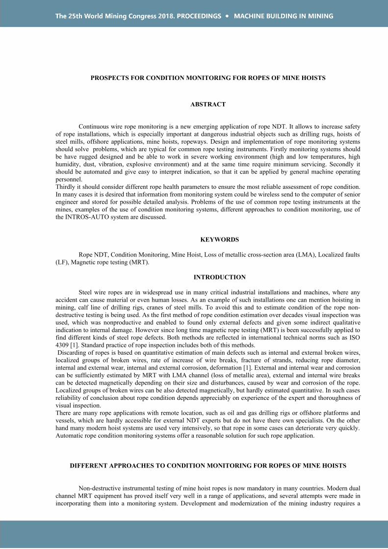
reduction in rope testing time, eliminating (reducing) the influence of the human factor, increasing the usability ofequipment.In 2014 Luoyang BECOT Friction Material of China. built a jig for the simultaneous installation of up to four"INTROS" testers, on rope hoists at a mine in Luoyang, (Figure 1). The jig is located at the zero mark of the shaftnear the driving drum. Information on the status of the ropes is registered in the and is available for analysis on apersonal computer using the Wintros software
Figure 1. Monitoring system for two rope hoists
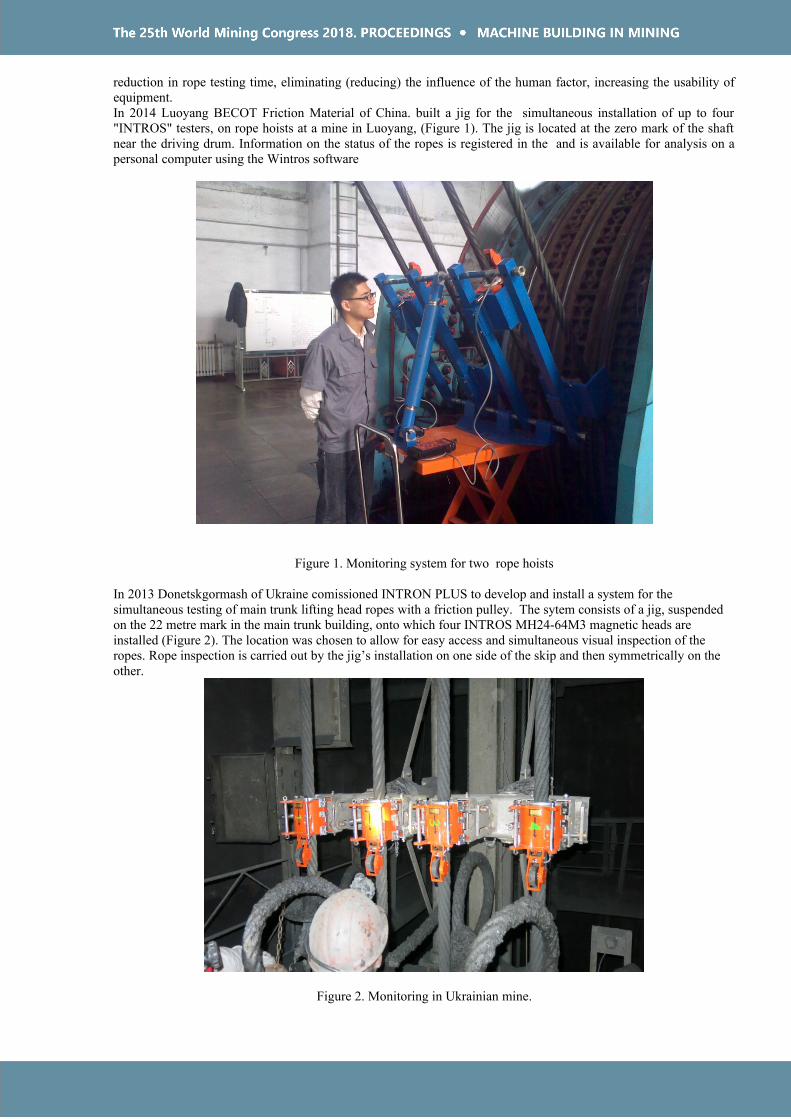
In 2013 Donetskgormash of Ukraine comissioned INTRON PLUS to develop and install a system for the simultaneous testing of main trunk lifting head ropes with a friction pulley. The sytem consists of a jig, suspended on the 22 metre mark in the main trunk building, onto which four INTROS MH24-64M3 magnetic heads are installed (Figure 2). The location was chosen to allow for easy access and simultaneous visual inspection of the ropes. Rope inspection is carried out by the jig’s installation on one side of the skip and then symmetrically on the other.
Figure 2. Monitoring in Ukrainian mine.

Another approach was implemented at a mine in South Africa. In Figure 3, it can be easily seen that four measuring heads are permanently mounted on multi rope hoist machine. This approach significantly reduces the rope testing time.
Figure 3. Monitoring in South Africa mine.
IMPLEMENTATION OF MAGNETIC ROPE MONITORING SYSTEM INTROS-AUTO
Rigid requirements for monitoring system are possible to meet only in highly specialized implementations, designedfor certain rope application. For example rope monitoring system Intros-Auto has several specific realizations: forhoisting block of drilling rigs, for hot-metal cranes of steel mills. Automatic system for monitoring of drilling rigropes consists of a compact magnetic head (MH), placed on the rope (Figure 4), connected with a control anddisplay unit (CDU), placed at console of drill tower operator (Figure 5). Monitoring system has explosive proofdesign, extended temperature range and IP 66 ingress protection, so it can be used in severe environment. Thesystem provides both operation modes: continuous monitoring and periodical automated rope testing. Magnetic headshown at Figure 4 is designed for periodical (every shaft) rope testing. MH is located permanently near the drum ina winch unit, this enables quickly and easy mounting and dismantling of MH at/from the rope, no additionalattachments are necessary. Inspection procedure is fully automated, so the operator should switch system on and offand see results at the display. To make indication more understandable it conforms with traffic light principle. Ifsome rope part with valuable deterioration passes through MH, CDU switch on yellow or red LED, depending ofrope condition (yellow light corresponds warning condition and red light – critical condition). So far no valuabledeterioration is found on the rope, green LED is on. In case the whole accessible length of the rope is checked it ispossible to use additional information from comparing successive inspections in order to find out, if the rope beginsto deteriorate intensively. At the end of inspection information about found defects is being displayed at CDU toenable an operator to check defects visually, if necessary. The system can store measurements of last several dozensinspection, this results can be send to some external computer via Wi-Fi or a cable. It is also possible to controlinspection process from remote computer on-line. The system implements both monitoring modes: continuous andperiodical. By demand inspection results can be analyzed by external expert so far measurements have the samerepresentation as common LMA- and LF-traces of general MRT instruments. Speed of the rope during inspectioncan be from 0.2 to 5 m/s.
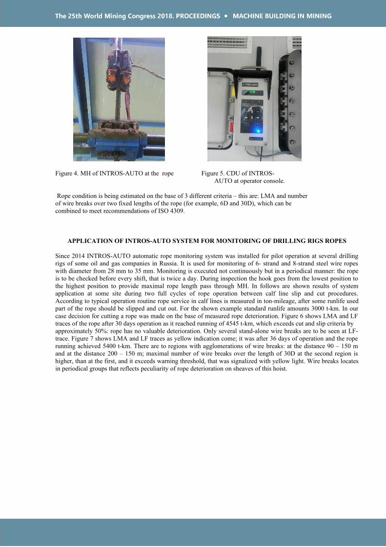
Figure 4. MH of INTROS-AUTO at the rope Figure 5. CDU of INTROS- AUTO at operator console.
Rope condition is being estimated on the base of 3 different criteria – this are: LMA and numberof wire breaks over two fixed lengths of the rope (for example, 6D and 30D), which can becombined to meet recommendations of ISO 4309.
APPLICATION OF INTROS-AUTO SYSTEM FOR MONITORING OF DRILLING RIGS ROPES
Since 2014 INTROS-AUTO automatic rope monitoring system was installed for pilot operation at several drillingrigs of some oil and gas companies in Russia. It is used for monitoring of 6- strand and 8-strand steel wire ropeswith diameter from 28 mm to 35 mm. Monitoring is executed not continuously but in a periodical manner: the ropeis to be checked before every shift, that is twice a day. During inspection the hook goes from the lowest position tothe highest position to provide maximal rope length pass through MH. In follows are shown results of systemapplication at some site during two full cycles of rope operation between calf line slip and cut procedures.According to typical operation routine rope service in calf lines is measured in ton-mileage, after some runlife usedpart of the rope should be slipped and cut out. For the shown example standard runlife amounts 3000 t-km. In ourcase decision for cutting a rope was made on the base of measured rope deterioration. Figure 6 shows LMA and LFtraces of the rope after 30 days operation as it reached running of 4545 t-km, which exceeds cut and slip criteria byapproximately 50%: rope has no valuable deterioration. Only several stand-alone wire breaks are to be seen at LF-trace. Figure 7 shows LMA and LF traces as yellow indication come; it was after 36 days of operation and the roperunning achieved 5400 t-km. There are to regions with agglomerations of wire breaks: at the distance 90 – 150 mand at the distance 200 – 150 m; maximal number of wire breaks over the length of 30D at the second region ishigher, than at the first, and it exceeds warning threshold, that was signalized with yellow light. Wire breaks locatesin periodical groups that reflects peculiarity of rope deterioration on sheaves of this hoist.
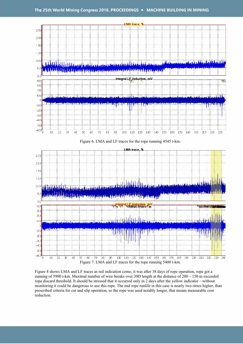
Figure 6. LMA and LF traces for the rope running 4545 t-km.
Figure 7. LMA and LF traces for the rope running 5400 t-km.
Figure 8 shows LMA and LF traces as red indication come; it was after 38 days of rope operation, rope got a running of 5900 t-km. Maximal number of wire breaks over 30D length at the distance of 200 – 150 m exceeded rope discard threshold. It should be stressed that it occurred only in 2 days after the yellow indicator – without monitoring it could be dangerous to use this rope. The end rope runlife in this case is nearly two times higher, than prescribed criteria for cut and slip operation, so the rope was used notably longer, that means measurable cost reduction.

Figure 8. LMA and LF traces for the rope running 5900 t-km.
To check a real condition of the rope the most deteriorated section was cut out and disassembled to count real number of broken wires. Figure 9 shows separate wires of one strand after it was unstranded. Maximal number of wire breaks at the lay length put together 27, that exceeds a discard criteria, which permits breakage of 10% of wiresat one lay length (corresponds to 6d), in this case – 21 wires. So system indication was correct.
Figure 9. Broken wires of one strand after its unstranding.
CONDITION MONITORING FOR ROPES OF MINE HOISTS
As it was shown in the above example, INTRON PLUS has a positive experience of using the INTROS-AUTO inthe monitoring of the calf lines. At present, this experience extends to the development of monitoring systems formine hoisting ropes. INTRON PLUS is now developing a monitoring system for the head ropes of the main trunk-lifting complex for Uralkaliy and EuroChem-VolgaKaliy on the basis of the INTROS-AUTO monitoring system.

The mine "10 years of independence of the Republic of Kazakhstan" of Donskoy Ore Mining and Processing Plant,TNC Kazchrome JSC (Figure 10) is also interested in development and purchasing of our condition monitoringsystem.
Figure 10. The mine "10 years of independence of the Republic of Kazakhstan”
The Figure 11 shows an example of the INTROS-AUTO system application for hoist machines. All MHs areconnected to the CDUs, which are located in the hoist operator cabin. MH is installed on the sheave wheel platformand securely anchored to stationary structures. MHs are to be installed on ropes during all technological proceduresof the mine-hoisting machine operating. The rope offset in the horizontal plane with respect to the axis of the pulleyshould not exceed 15 mm. This requirement is achievable, since the wobble of the rope in the sheave wheelsplatform space is nonsignificant. The CDUs is installed in the hoist operator cab and connected to the MH with acable and another cable is connecting CDU with the encoder of the hoist machine control system. The CDUtransfers the recorded data to an external computer or a hoist operator's computer via the WiFi or via an RS 485cable.
Figure 11. The example of application of the INTROS-AUTO system
During the operation of the conditions monitoring system of mine hoisting installations, highly qualified personnel is not required for carrying out non-destructive testing,, which significantly reduces the charges of the enterprise.

CONCLUSION
The above examples show that whilst use of standard MRT equipment is possible for monitoringpurposes,a dedicated automated system allows for more timid operation at much less operating costs.
REFERENCES
1. ISO 4309:2017 International standard. Cranes – Wire ropes – Care and maintenance, inspection and discard.
2. Slesarev D., Sukhorukov V., Semenov A. Application of MFL nondestructive testing for automated rope condition monitoring. – 11 European Conference on NDT. Book of Abstracts: Prague, 2014, p. 64.
3. Anisimov A., Shpakov I. Rope condition monitoring of mine hoists. Mining journal of Kazakhstan N9, 2015, p. 41.
Related Documents