Mohd. Hanif Dewan, Senior Engg. Lecturer, International Maritime Academy, Bangladesh. 1 PROPERTIES OF FUEL OIL AND BUNKERING PROCEDURE -Mohd. Hanif Dewan, Senior Engg. Lecturer, International Maritime Academy, Bangladesh.

Welcome message from author
This document is posted to help you gain knowledge. Please leave a comment to let me know what you think about it! Share it to your friends and learn new things together.
Transcript
Mohd. Hanif Dewan, Senior Engg. Lecturer, International Maritime Academy, Bangladesh. 1
PROPERTIESOF FUEL OIL
ANDBUNKERINGPROCEDURE
-Mohd. Hanif Dewan, Senior Engg. Lecturer,International Maritime Academy, Bangladesh.
Mohd. Hanif Dewan, Senior Engg. Lecturer, International Maritime Academy, Bangladesh. 2
Definition of Fuel:
Each substance which gives energy after burning is called fuel.
Fuels are classification by sources:a. Naturalb. Artificial
Fuels are classification by phases:a. Solid – coal, wood etc.b. Liquid – petroleum products, alcohol, biofuel etc.c. Gas – methane, butane, hydrogen, biogas etc.
Generally Liquid fuels are preferential.1. Energy per gram is too high2. Fast conversion of chemical energy to thermal energy3. Easy mix with oxygen4. No ash after combustion5. Easy transport and storage
Every liquid substance which provides the sufficient thermal energy can be used as afuel for internal combustion engines.
PETROLEUM PRODUCTION:
Petrolem = Petra + OleumRock + Oil
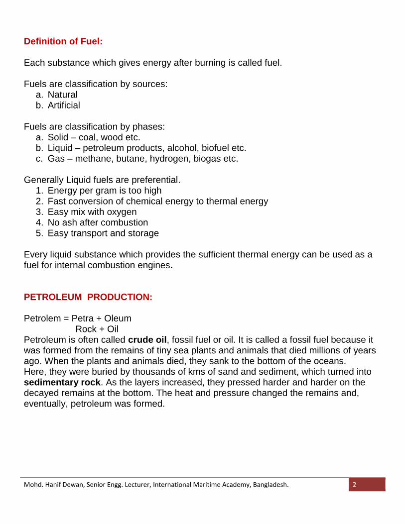
Petroleum is often called crude oil, fossil fuel or oil. It is called a fossil fuel because itwas formed from the remains of tiny sea plants and animals that died millions of yearsago. When the plants and animals died, they sank to the bottom of the oceans.Here, they were buried by thousands of kms of sand and sediment, which turned intosedimentary rock. As the layers increased, they pressed harder and harder on thedecayed remains at the bottom. The heat and pressure changed the remains and,eventually, petroleum was formed.
Mohd. Hanif Dewan, Senior Engg. Lecturer, International Maritime Academy, Bangladesh. 3
Petroleum is defined by 4 physical categories historically:1. Boiling point2. Density3. Odour4. Viscosity
Light-heavy: Low boiling point and relative densityHeavy-heavy: High boiling point, viscous.
Because crude oil has Fe, Mg, Ca, P, V, S, Zn, Co, clay, water and otherresiduals, it has to distillate for internal combustion engines.
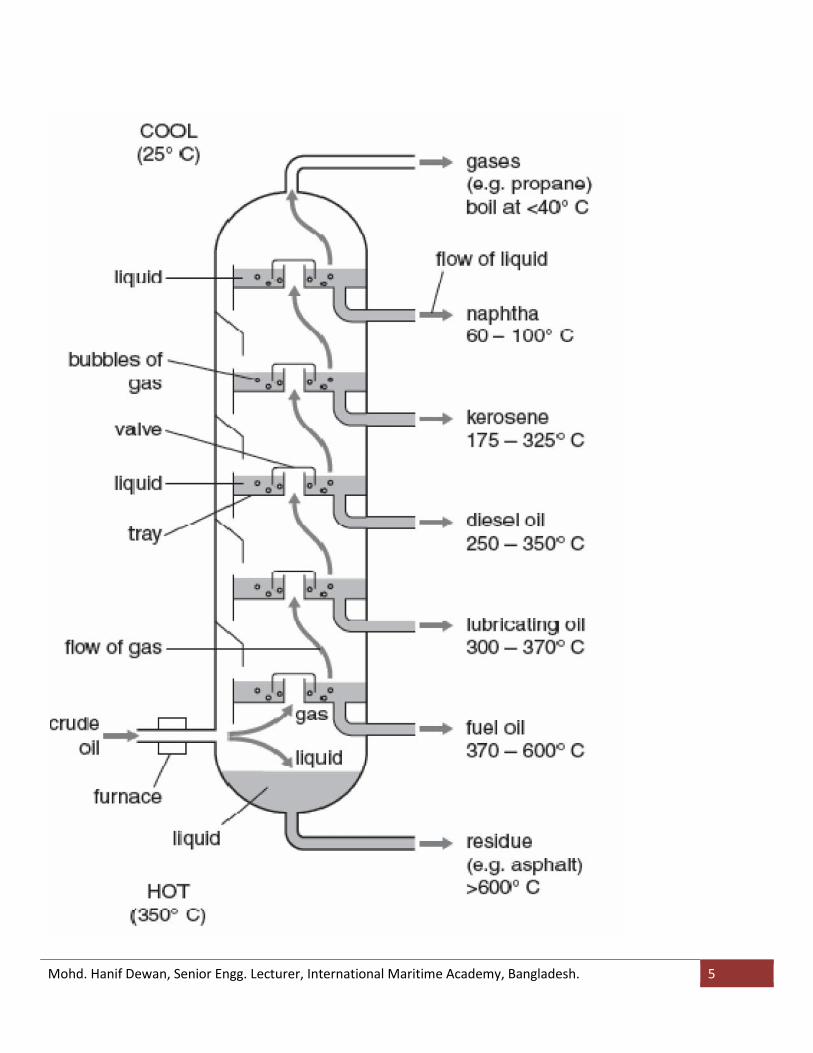
Fractional Distillation Of Crude Oil
Fractional distillation of crude oil is the first step in the production of manyof the materials we have come to rely on in modern life.All our fossil fuels, virtually all our plastics, detergents and commercial alcoholsare made from products of this process.In order to separate the different length chains in the crude mix, it is heated to avery high temperature.The temperature cannot be set higher than this as there is a risk that the lighterfractions will ignite.
Distillation is the most common form of separation technology used in petroleumrefineries, petrochemical and chemical plants, natural gas processing.Industrial distillation is typically performed in large, vertical cylindrical columns
Mohd. Hanif Dewan, Senior Engg. Lecturer, International Maritime Academy, Bangladesh. 4
known as "distillation or fractionation towers" or "distillation columns" withdiameters ranging from about 65 centimetres to 6 metres and heights rangingfrom about 6 metres to 60 metres or more.
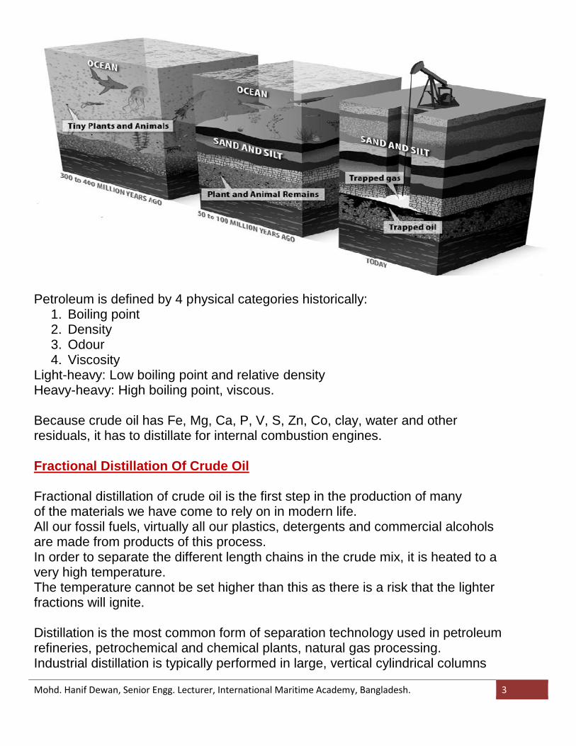
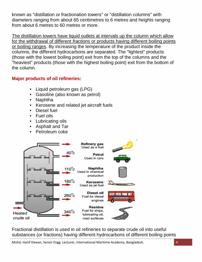
The distillation towers have liquid outlets at intervals up the column which allowfor the withdrawal of different fractions or products having different boiling pointsor boiling ranges. By increasing the temperature of the product inside thecolumns, the different hydrocarbons are separated. The "lightest" products(those with the lowest boiling point) exit from the top of the columns and the"heaviest" products (those with the highest boiling point) exit from the bottom ofthe column.
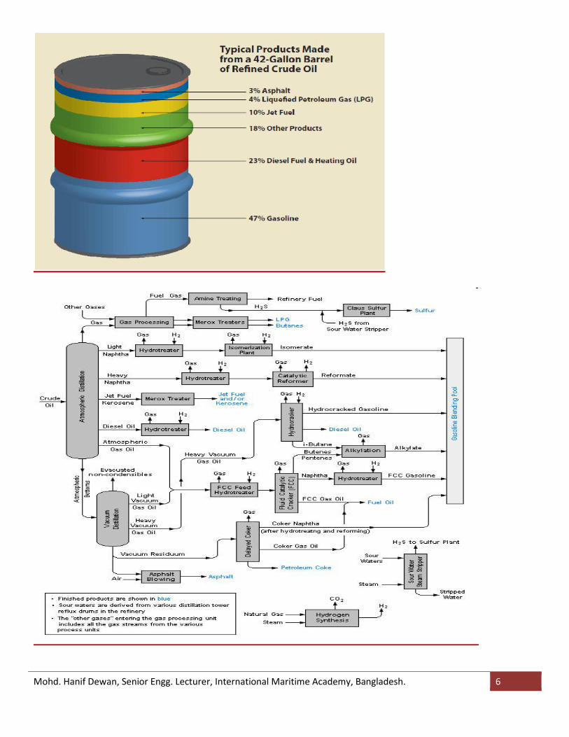
Major products of oil refineries:
• Liquid petroleum gas (LPG)• Gasoline (also known as petrol)• Naphtha• Kerosene and related jet aircraft fuels• Diesel fuel• Fuel oils• Lubricating oils• Asphalt and Tar• Petroleum coke
Fractional distillation is used in oil refineries to separate crude oil into usefulsubstances (or fractions) having different hydrocarbons of different boiling points
Mohd. Hanif Dewan, Senior Engg. Lecturer, International Maritime Academy, Bangladesh. 5
Mohd. Hanif Dewan, Senior Engg. Lecturer, International Maritime Academy, Bangladesh. 6
Mohd. Hanif Dewan, Senior Engg. Lecturer, International Maritime Academy, Bangladesh. 7
Product Definitions
The products refined from the liquid fractions of crude oil can be placed into ten maincategories:
AsphaltAsphalt is commonly used to make roads. It is a colloid of asphaltenes and maltenesthat is separated from the other components of crude oil by fractional distillation.Once asphalt is collected, it is processed in a de-asphalting unit, and then goesthrough a process called “blowing” where it is reacted with oxygen to make it harden.Asphalt is usually stored and transported at around 150 C.
DieselDiesel is any fuel that can be used in a diesel engine. Diesel is produced by fractionaldistillation between 250° Fahrenheit and 350° Fahrenheit. Diesel has a higher densitythan gasoline and is simpler to refine from crude oil. It is most commonly used intransportation.
Fuel OilFuel oil is any liquid petroleum product that is burned in a furnace to generate heat.Fuel oil is also the heaviest commercial fuel that is produced from crude oil.
GasolineIt is mainly used as fuel in internal combustion engines, like the engines in cars.Gasoline is a mixture of paraffins, naphthenes, and olefins, although the specific ratiosof these parts depends on the refinery where the crude oil is processed. Gasolinerefined beyond fractional distillation is often enhanced with iso-octane and ethanol sothat it is usable in cars.Gasoline is called different things in different parts of the world. Some of these namesare: petrol, petroleum spirit, gas, petrogasoline, and mogas.
KeroseneKerosene is collected through fractional distillation at temperatures between 150°Fahrenheit and 275° Fahrenheit. It is a combustible liquid that is thin and clear.Kerosene is most commonly used as jet fuel and as heating fuel.
Liquefied Petroleum GasLiquefied petroleum gas is a mixture of gases that are most often used in heatingappliances, aerosol propellants, and refrigerants. Different kinds of liquefied petroleumgas, or LPG, are propane and butane. At normal atmospheric pressure, liquefiedpetroleum gas will evaporate, so it needs to be contained in pressurized steel bottles.
Mohd. Hanif Dewan, Senior Engg. Lecturer, International Maritime Academy, Bangladesh. 8
Lubricating OilLubricating oils consist of base oils and additives.Different lubricating oils are classified as paraffinic, naphthenic, or aromatic.Lubricating oils are used between two surfaces to reduce friction and wear. The mostcommonly-known lubricating oil is motor oil, which protects moving parts inside aninternal combustion engine.
Paraffin WaxParaffin wax is a white, odorless, tasteless, waxy solid at room temperature. Themelting point of paraffin wax is between 47° C and 65° C, depending on other factors.It is an excellent electrical insulator, second only to Teflon®, a specialized product ofpetroleum. Paraffin wax is used in drywall to insulate buildings. It is also an acceptablewax used to make candles.
BitumenBitumen, commonly known as tar, is a thick, black, sticky material. Refined bitumen isthe bottom fraction obtained by the fractional distillation of crude oil. This means thatthe boiling point of bitumen is very high, so it does not rise in the distillation chamber.The boiling point of bitumen is 525° C. Bitumen is used in paving roads andwaterproofing roofs and boats. Bitumen is also made into thin plates and used tosoundproof dishwashers and hard drives in computers.
Fuel Properties
Flash point The flash point of a fuel is the temperature at which vapour given off will ignite
when an external flame is applied under specified test conditions. A flash point isdefined to minimise fire risk during normal storage and handling.
The minimum flash point for fuel in the machinery space of a merchant ship isgoverned by international legislation and the value is 60oC. For fuels used foremergency purposes, external to the machinery space, for example the lifeboats,the flash point must be greater than 43oC.
Residual fuels are capable of producing light hydrocarbons in the tankheadspace, near to or within the flammable range. Hence all residual fuel oilheadspaces should be considered to be potentially flammable.
Fire PointThe temperature at which the hydraulic fluid surface emits enough vapor to sustain afire for five seconds in the presence of a flame.
Cloud Point
Mohd. Hanif Dewan, Senior Engg. Lecturer, International Maritime Academy, Bangladesh. 9
The cloud point of a diesel fuel is the temperature at which the amount of precipitatedwax crystals becomes large enough to make the fuel appear cloudy or hazy. Wax mayform because normal paraffins occur naturally in diesel fuel. As the temperature of thefuel is lowered, these paraffins become less soluble in the fuel and precipitate out aswax crystals.
Pour PointPour point is the lowest temperature at which the fuel will flow and is used to predictthe lowest temperature at which the fuel can be pumped.
FlammabilityThe ability or tendency to ignite and burn when exposed to an open flame.
FluidityA hydraulic fluid's ability to flow. As temperature increases, fluidity increases.
SPECIFIC HEATSpecific heat is the amount of kCals needed to raise the temperature of 1 kg of oil by
1°C. The unit of specific heat is kcal/kg 0 C. It varies from 0.22 to 0.28 depending onthe oil specific gravity. The specific heat determines how much steam or electricalenergy it takes to heat oil to a desired temperature. Light oils have a low specific heat,whereas heavier oils have a higher specific heat.
DENSITY:Density is the absolute relationship between mass and volume at a stated temperature.The SI unit is kg/m 3 at a reference temperature, typically 15°C.
API:In the United States and some other countries, the density of petroleum products isdefined in terms of API gravity. This is an arbitrary scale adopted by the AmericanPetroleum Institute for expressing the relative density of oils.API= (141.5/RD at 60/60oF) – 131.5
Density in vacuum and in airThe terms 'density in vacuo' or 'density in air' are sometimes used on fuel delivery orbunker receipt notes. As density is the absolute relationship between mass and volumeand not its weight to volume, by definition density is in vacuo. Although often used, theterm 'density in air' is incorrect and should be referred to as a 'weight factor'. This isbecause a substance weighed in air is supported to a small extent by the buoyancy ofair acting on it. Thus the weight of a liquid in air is slightly less than the weight in
Mohd. Hanif Dewan, Senior Engg. Lecturer, International Maritime Academy, Bangladesh. 10
vacuo. There is no simple relationship between density and 'weight factor' but forbunker fuels the difference approximates to 1.1 kg/m 3 . To convert density at 15°C tothe 'weight factor' at 15°C, 1.1 kg/m3 should be deducted.
Density adjustment at temperatures other than 15oC:Densities are measured over a range of temperatures, usually for convenience, at thetemperature at which the fuel is stored. The value is then corrected back in testequipment or by the use of standard tables to the reference temperature.
EFFECT OF VARIATION IN DENSITY
The effect of injecting heavy oil with increased density will result in increasedcompared to diesel oil: Power - Increased power because of increase in heat energy being injected Speed – Increase in speed of the engine. Texh- Higher exhaust temperature because of more power being produced Pcomp- because of increase in Turbocharger speed Pmax- Increase because of increase in Pcomp and more heat energy being
injected.
Reduction in density will have the opposite effect.
SPECIFIC GRAVITYThis is defined as the ratio of the weight of a given volume of oil to the weight of thesame volume of water at a given temperature. The density of fuel, relative to water, iscalled specific gravity. The specific gravity of water is defined as 1. Since specificgravity is a ratio, it has no units. The measurement of specific gravity is generally madeby a hydrometer.
Specific gravity is used in calculations involving weights and volumes. The specificgravity of various fuel oils are given in Table below:
VISCOSITYThe viscosity of a fluid is a measure of its internal resistance to flow. Viscosity dependson the temperature and decreases as the temperature increases. Any numerical valuefor viscosity has no meaning unless the temperature is also specified. Viscosity ismeasured in Stokes / Centistokes. Sometimes viscosity is also quoted in Engler,Saybolt or Redwood.
Each type of oil has its own temperature - viscosity relationship. The measurement ofviscosity is made with an instrument called a Viscometer.
Mohd. Hanif Dewan, Senior Engg. Lecturer, International Maritime Academy, Bangladesh. 11
Viscosity is the most important characteristic in the storage and use of fuel oil. Itinfluences the degree of pre- heating required for handling, storage and satisfactoryatomization. If the oil is too viscous, it may become difficult to pump, hard to light theburner, and difficult to handle. Poor atomization may result in the formation of carbondeposits on the burner tips or on the walls. Therefore pre-heating is necessary forproper atomization.
DYNAMIC VISCOSITYDynamic viscosity also termed as absolute viscosity, is the tangential force per unitarea required to move one horizontal plane with respect to the other at unit velocitywhen maintained a unit distance apart by the fluid. When the fluid thickness is 1 cm,the force 1 dyne/cm2, the velocity 1cm/s the absolute viscosity is 1POISE.As the units are large it is more common to divide them by 100, resultant smaller unitsbeing CENTIPOISE.1 centipoises= 1 milliPascal second . [Pascal= 1N/m2]The SI symbol is ‘ή’ and SI unit is N.s/m2.
CENTISTOKEA unit of measurement for kinematic viscosity equal to the unit millimeters squared persecond. The centistoke is the ratio of a liquid's absolute viscosity in centipoise to thedensity.
KINEMATIC VISCOCITY: It is the ratio of viscosity to the density of fuel.Unit of kinematic viscosity is CENTISTOKE (cst) = centipoise / densityIt can be found out that 1 cSt =10-6m2/sec.
VISCOSITY OF ORDERED FUELFuel may have been ordered to one of the grades in ISO 8217, frequently on delivery,only the viscosity grade is stated. For example IF 180 this means that the viscosity is amaximum of 180 cSt at 50°C.
VISCOSITY TEMPERATURE RELATIONSHIPBecause of the viscosity/temperature relationship, a few degrees change could make abig difference to the injection viscosity. In practical terms, this means that if the actualfuel viscosity is greater than that ordered, it is likely that the fuel oil heater canaccommodate this.
Mohd. Hanif Dewan, Senior Engg. Lecturer, International Maritime Academy, Bangladesh. 12
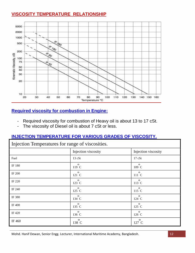
VISCOSITY TEMPERATURE RELATIONSHIP
Required viscosity for combustion in Engine:
- Required viscosity for combustion of Heavy oil is about 13 to 17 cSt.- The viscosity of Diesel oil is about 7 cSt or less.
INJECTION TEMPERATURE FOR VARIOUS GRADES OF VISCOSITY.Injection Temperatures for range of viscosities.
Injection viscosity Injection viscosity
Fuel 13 cSt 17 cSt
IF 180 119O
C 109O
C
IF 200 121O
C 111O
C
IF 220 123O
C 113O
C
IF 240 125O
C 115O
C
IF 380 134O
C 124O
C
IF 400 135O
C 125O
C
IF 420 136O
C 126O
C
IF 460 138OC 127
OC
Mohd. Hanif Dewan, Senior Engg. Lecturer, International Maritime Academy, Bangladesh. 13
VISCOSITY INDEX:- It is a numerical value which measures the ability of the oil to resist viscosity
change when the temperature changes.- A high viscosity index would refer to an oil capable of maintaining a fairly
constant velocity value in spite of wide variation in the temperature.- The value of viscosity index is usually determined from a chart based on
knowledge of the viscosity values at different temperatures.
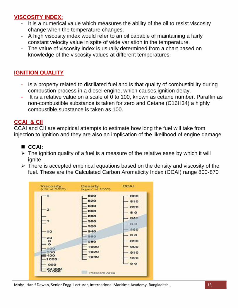
IGNITION QUALITY
- Is a property related to distillated fuel and is that quality of combustibility duringcombustion process in a diesel engine, which causes ignition delay.
- It is a relative value on a scale of 0 to 100, known as cetane number. Paraffin asnon-combustible substance is taken for zero and Cetane (C16H34) a highlycombustible substance is taken as 100.
CCAI & CIICCAI and CII are empirical attempts to estimate how long the fuel will take frominjection to ignition and they are also an implication of the likelihood of engine damage.
CCAI: The ignition quality of a fuel is a measure of the relative ease by which it will
ignite There is accepted empirical equations based on the density and viscosity of the
fuel. These are the Calculated Carbon Aromaticity Index (CCAI) range 800-870
Mohd. Hanif Dewan, Senior Engg. Lecturer, International Maritime Academy, Bangladesh. 14
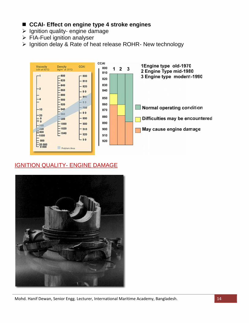
CCAI- Effect on engine type 4 stroke engines Ignition quality- engine damage FIA-Fuel ignition analyser Ignition delay & Rate of heat release ROHR- New technology
IGNITION QUALITY- ENGINE DAMAGE
Mohd. Hanif Dewan, Senior Engg. Lecturer, International Maritime Academy, Bangladesh. 14
CCAI- Effect on engine type 4 stroke engines Ignition quality- engine damage FIA-Fuel ignition analyser Ignition delay & Rate of heat release ROHR- New technology
IGNITION QUALITY- ENGINE DAMAGE
Mohd. Hanif Dewan, Senior Engg. Lecturer, International Maritime Academy, Bangladesh. 14
CCAI- Effect on engine type 4 stroke engines Ignition quality- engine damage FIA-Fuel ignition analyser Ignition delay & Rate of heat release ROHR- New technology
IGNITION QUALITY- ENGINE DAMAGE
Mohd. Hanif Dewan, Senior Engg. Lecturer, International Maritime Academy, Bangladesh. 15
EFFECT OF TIME BETWEEN INJECTION AND START OF INJECTION.- Fuel takes a finite time from the start of the injection to the start of combustion.- During this period, fuel is intimately mixed with the hot compressed air in the
cylinder where it begins to vaporize.- After a short delay known as the ignition delay, the heat of compression causes
spontaneous ignition to occur.- Rapid uncontrolled combustion follows as the accumulated vapour formed during
the initial injection phase is vigorously burned.- The longer the ignition delay, the more fuel will have been injected and vaporized
during this “pre-mixed” phase and the more explosive will be the initialcombustion.
EFFECT OF TIME BETWEEN INJECTION AND START OF INJECTION.- Rapid pre-mixed combustion causes very rapid rates of pressure rise in the
cylinder resulting in shock waves, broken piston rings and overheating of metalsurfaces.
- Large diesel engines are designed to withstand a certain rate of pressure risewithin the cylinder although the figure will vary between different designs.
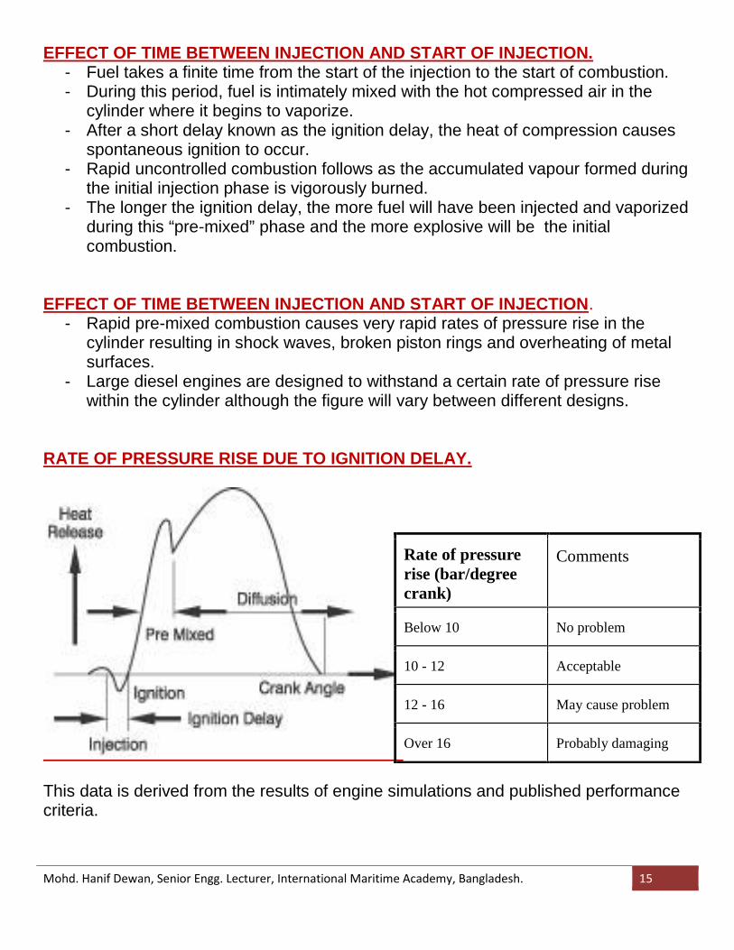
RATE OF PRESSURE RISE DUE TO IGNITION DELAY.
This data is derived from the results of engine simulations and published performancecriteria.
Rate of pressurerise (bar/degreecrank)
Comments
Below 10 No problem
10 - 12 Acceptable
12 - 16 May cause problem
Over 16 Probably damaging
Mohd. Hanif Dewan, Senior Engg. Lecturer, International Maritime Academy, Bangladesh. 16
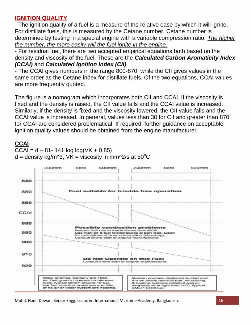
IGNITION QUALITY- The ignition quality of a fuel is a measure of the relative ease by which it will ignite.For distillate fuels, this is measured by the Cetane number. Cetane number isdetermined by testing in a special engine with a variable compression ratio. The higherthe number, the more easily will the fuel ignite in the engine.- For residual fuel, there are two accepted empirical equations both based on thedensity and viscosity of the fuel. These are the Calculated Carbon Aromaticity Index(CCAI) and Calculated Ignition Index (CII).- The CCAI gives numbers in the range 800-870, while the CII gives values in thesame order as the Cetane index for distillate fuels. Of the two equations, CCAI valuesare more frequently quoted.
The figure is a nomogram which incorporates both CII and CCAI. If the viscosity isfixed and the density is raised, the CII value falls and the CCAI value is increased.Similarly, if the density is fixed and the viscosity lowered, the CII value falls and theCCAI value is increased. In general, values less than 30 for CII and greater than 870for CCAI are considered problematical. If required, further guidance on acceptableignition quality values should be obtained from the engine manufacturer.
CCAICCAI = d – 81- 141 log log(VK + 0.85)d = density kg/m^3, VK = viscosity in mm^2/s at 50oC
Mohd. Hanif Dewan, Senior Engg. Lecturer, International Maritime Academy, Bangladesh. 17
CETANE NUMBER- It is an indication of the ignition quality of the fuel.- In a compression ignition engine the time interval between fuel injection and
firing, called ignition delay, must not be too long otherwise collected fuel willgenerate high pressures when it ignites and diesel knock results.
- Paraffin hydrocarbons have the best ignition quality.
CETANE NUMBER AND DENSITY- Density is often indicative of cetane number especially in the middle ranges, i.e.,
density 850 kg/m3, cetane number about 61, density 950 kg/cm3, cetane numberabout 37.
- Acetone peroxide used as additives to improve cetane number.
CALORIFIC VALUEThe specific energy of a fuel expressed in MJ/kg depends on the composition. Forresidual fuel, the main constituents are carbon and hydrogen, both of which releaseenergy on combustion. Sulphur also releases energy on combustion but to a lesserextent than carbon and hydrogen.
CARBON RESIDUE:The carbon residue of a fuel is the tendency to form carbon deposits under hightemperature conditions in an inert atmosphere. It may be expressed as RamsbottomCarbon Residue (RCR), Conradson Carbon Residue (CCR) or Micro Carbon Residue(MCR). Numerically, the CCR value is the same as that of MCR. The carbon residuevalue is considered by some to give an approximate indication of the combustibility anddeposit forming tendencies of the fuel.CARBON RESIDUE:The carbon residue value of a fuel depends upon the refinery processes employed inits manufacture. On a global basis, this is typically 15-16% m/m but in some areas canbe as high as 20% m/m.
SULPHUR residual fuel the value is in the order or 1.5-4 % m/m. marginal effect on the specific energy The corrosive effect of sulphuric acid during combustion is counteracted by
adequate lube oils and temperature control of the combustion chamber
WATER The ingress of water can come from a number of sources, which include tank
condensation and tank leakage
Mohd. Hanif Dewan, Senior Engg. Lecturer, International Maritime Academy, Bangladesh. 18
removed by centrifuging the fuel before use. This applies especially to salt water,the sodium content of which can result in deposits on valves and turbochargers.
If water cannot be removed, homogenizing after centrifuging is recommended.
ASH Ash represents solid contaminants as well as metals present in the fuel in soluble
compounds (vanadium). Part of the ash could be catalyst particles from therefining process.
Such particles are highly abrasive. Solid ash should be removed to the widest possible extent by centrifuging, and
cleaning can be improved by installing a fine filter after the centrifuge e.g 5 – 10microns.
Vanadium and Sodium Vanadium is present in the fuel in soluble compounds and, consequently, cannot
be removed. Vanadium, in combination with sodium, may lead to exhaust valve corrosion and
turbocharger deposits. This can occur especially if the weight ratio of sodium to vanadium exceeds 1:3,
and especially in the case of a high vanadium content. Vanadium deposits can be so hard that they can cause extensive damage to the
TC nozzle ring and turbine wheel. The only way to remove vanadium depositsis to disassemble the components
and remove the deposits mechanically. Vanadium & Sodium- High temperature corrosion
Sodium is normally present in the fuel as a salt water contamination and may, assuch, be removed by centrifuging.
Sodium can also reach the engine in the form of airborne sea water mist.
Aluminium and silicon Aluminium and silicon limits content of catalytic fines, mainly Al2O3 and SiO2, in
the oil. 80 mg Al and Si corresponds to up to 170 mg Al2O2 and SiO2. Catalytic fines give rise to abrasive wear, reduced by centrifuging the fuel oil
before it reaches the engine, and 5- 10 micron fine filter after the centrifuge Catalytic fines imbedded in piston ring
Mohd. Hanif Dewan, Senior Engg. Lecturer, International Maritime Academy, Bangladesh. 19
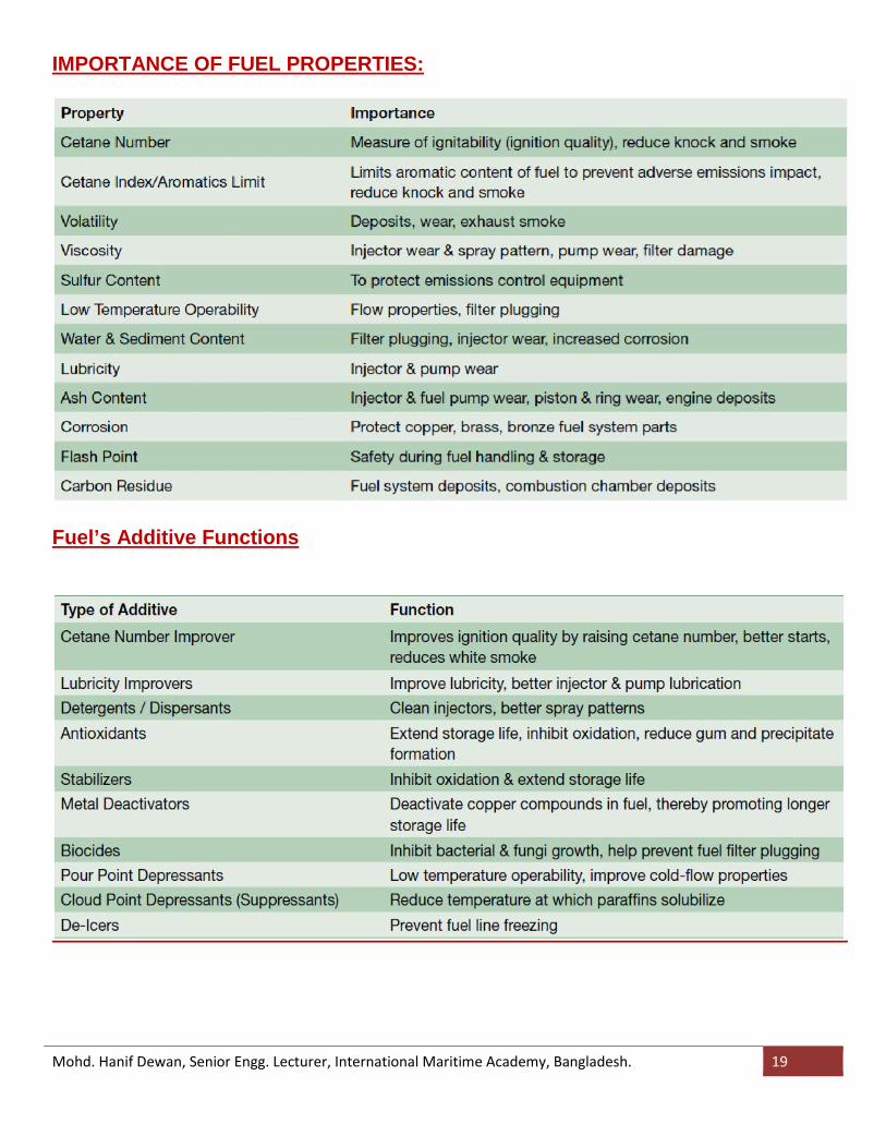
IMPORTANCE OF FUEL PROPERTIES:
Fuel’s Additive Functions
Mohd. Hanif Dewan, Senior Engg. Lecturer, International Maritime Academy, Bangladesh. 20
In the maritime field another type of classification is used for fuel oils:
MGO (Marine gas oil) - roughly equivalent to No. 2 fuel oil, made from distillateonly
MDO (Marine diesel oil) - A blend of heavy gasoil that may contain very smallamounts of black refinery feed stocks, but has a low viscosity up to 12 cSt so itneed not be heated for use in internal combustion engines
IFO (Intermediate fuel oil) A blend of gasoil and heavy fuel oil, with less gasoilthan marine diesel oil
MFO (Marine fuel oil) - same as HFO (just another "naming") HFO (Heavy fuel oil) - Pure or nearly pure residual oil, roughly equivalent to No. 6
fuel oilMarine diesel oil contains some heavy fuel oil, unlike regular diesels. Also, marine fueloils sometimes contain waste products such as used motor oil.
CCAI and CII are two indexes which describe the ignition quality of residual fuel oil,and CCAI is especially often calculated for marine fuels. Despite this marine fuels arestill quoted on the international bunker markets with their maximum viscosity (which isset by the ISO 8217 standard - see below) due to the fact that marine engines aredesigned to use different viscosities of fuel. The unit of viscosity used isthe Centistoke and the fuels most frequently quoted are listed below in order of cost,the least expensive first-
IFO 380 - Intermediate fuel oil with a maximum viscosity of 380 Centistokes (<3.5%sulphur)
IFO 180 - Intermediate fuel oil with a maximum viscosity of 180 Centistokes (<3.5%sulphur)
LS 380 - Low-sulphur (<1.0%) intermediate fuel oil with a maximum viscosity of 380Centistokes
LS 180 - Low-sulphur (<1.0%) intermediate fuel oil with a maximum viscosity of 180Centistokes
MDO - Marine diesel oil. MGO - Marine gasoil. LSMGO - Low-sulphur (<0.1%) Marine Gas Oil - The fuel is to be used in EU
community Ports and Anchorages. EU Sulphur directive 2005/33/EC ULSMGO - Ultra Low Sulphur Marine Gas Oil - referred to as Ultra Low Sulfur
Diesel (sulphur 0.0015% max) in the US and Auto Gas Oil (sulphur 0.001% max) inthe EU. Maximum sulphur allowable in US territories and territorial waters (inland,marine and automotive) and in the EU for inland use.
Mohd. Hanif Dewan, Senior Engg. Lecturer, International Maritime Academy, Bangladesh. 21
Low Sulphur Fuels
Sulphur contained in the fuel forms metallic sulphides that coat the internalsurfaces of the fuel injection equipment including the fuel pumps and the fuelinjectors. These sulphides have low shear resistance and act as EP additivessimilar to that found in lubrication oils. Extremely low sulphur fuels in use on theautomotive transport industry have led to the use of lubricity additives. In themarine environment the reduction in sulphur content has been less dramatic.
Marpol Annex VI(regulation 14) and the creation of Sulphur Emission ControlArea means it wil be a requirement to use only fuels with a certain maximumsulphur content. In the addition to the increased cost of these low sulphur fuels itis necessary to factor in the possibility of increased wear and tear on the enginecomponents.
Low sulphur fuels are normally low viscosity oils such as gas oil. Carefullplanning has to be done both at the design level ( to ensure sufficient storagecapacity) and at the operational and maintenance levels due to the knowndifficulties in changing over from a heated fuel to a non heated or one withreduced heating capacity.
The first British standard for fuel oil came in 1982. The latest standard is ISO 8217from 2005. The ISO standard describe four qualities of distillate fuels and 10 qualitiesof residual fuels. Over the years the standards have become stricter onenvironmentally important parameters such as sulfur content. The latest standard alsobanned the adding of used lubricating oil (ULO).
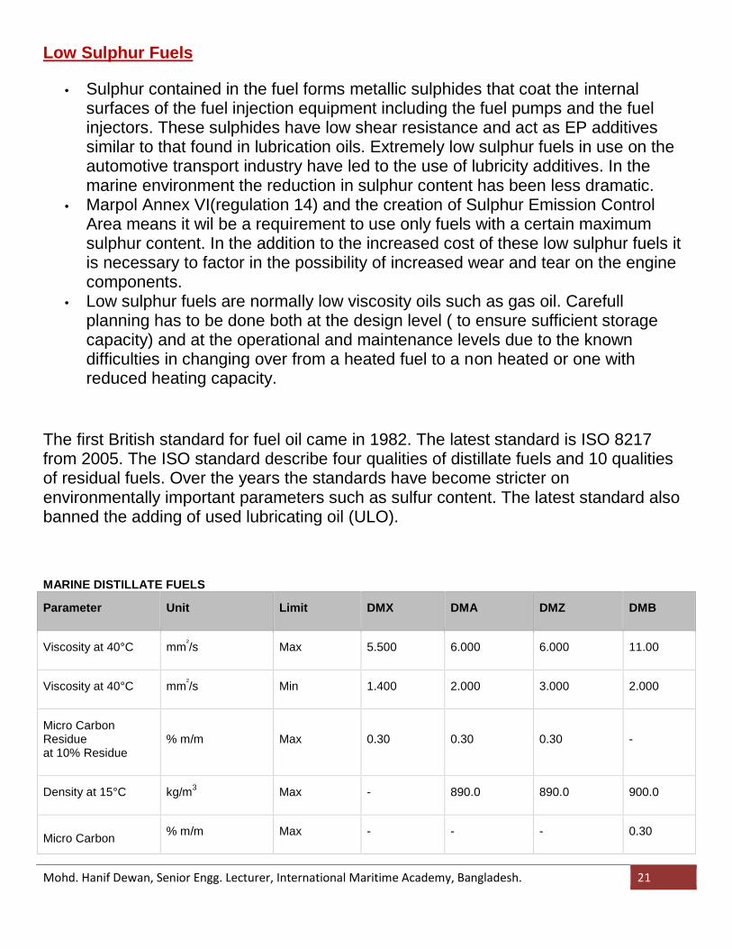
MARINE DISTILLATE FUELS
Parameter Unit Limit DMX DMA DMZ DMB
Viscosity at 40°C mm²/s Max 5.500 6.000 6.000 11.00
Viscosity at 40°C mm²/s Min 1.400 2.000 3.000 2.000
Micro CarbonResidueat 10% Residue
% m/m Max 0.30 0.30 0.30 -
Density at 15°C kg/m3 Max - 890.0 890.0 900.0
Micro Carbon % m/m Max - - - 0.30
Mohd. Hanif Dewan, Senior Engg. Lecturer, International Maritime Academy, Bangladesh. 22
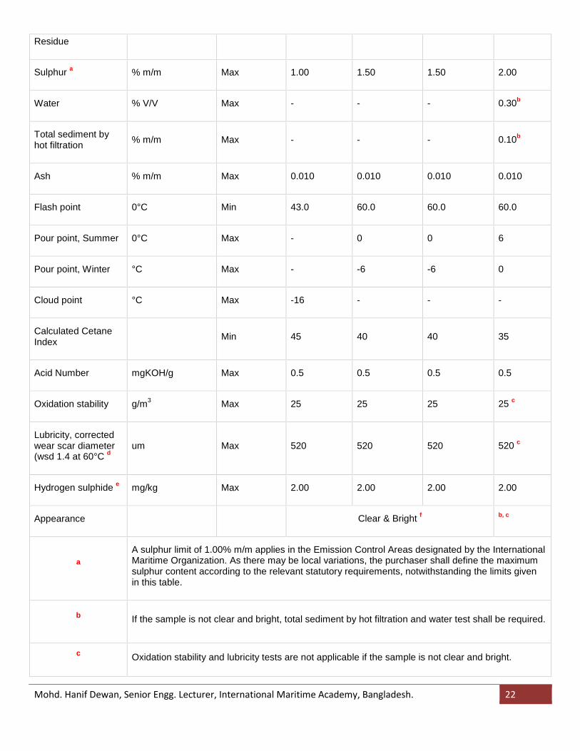
Residue
Sulphur a % m/m Max 1.00 1.50 1.50 2.00
Water % V/V Max - - - 0.30b
Total sediment byhot filtration % m/m Max - - - 0.10b
Ash % m/m Max 0.010 0.010 0.010 0.010
Flash point 0°C Min 43.0 60.0 60.0 60.0
Pour point, Summer 0°C Max - 0 0 6
Pour point, Winter °C Max - -6 -6 0
Cloud point °C Max -16 - - -
Calculated CetaneIndex Min 45 40 40 35
Acid Number mgKOH/g Max 0.5 0.5 0.5 0.5
Oxidation stability g/m3 Max 25 25 25 25 c
Lubricity, correctedwear scar diameter(wsd 1.4 at 60°C d
um Max 520 520 520 520 c
Hydrogen sulphide e mg/kg Max 2.00 2.00 2.00 2.00
Appearance Clear & Bright f b, c
aA sulphur limit of 1.00% m/m applies in the Emission Control Areas designated by the InternationalMaritime Organization. As there may be local variations, the purchaser shall define the maximumsulphur content according to the relevant statutory requirements, notwithstanding the limits givenin this table.
b If the sample is not clear and bright, total sediment by hot filtration and water test shall be required.
c Oxidation stability and lubricity tests are not applicable if the sample is not clear and bright.
Mohd. Hanif Dewan, Senior Engg. Lecturer, International Maritime Academy, Bangladesh. 23
d Applicable if sulphur is less than 0.050% m/m.
e Effective only from 1 July 2012.
f If the sample is dyed and not transparent, water test shall be required. The water content shall notexceed 200 mg/kg (0.02% m/m).
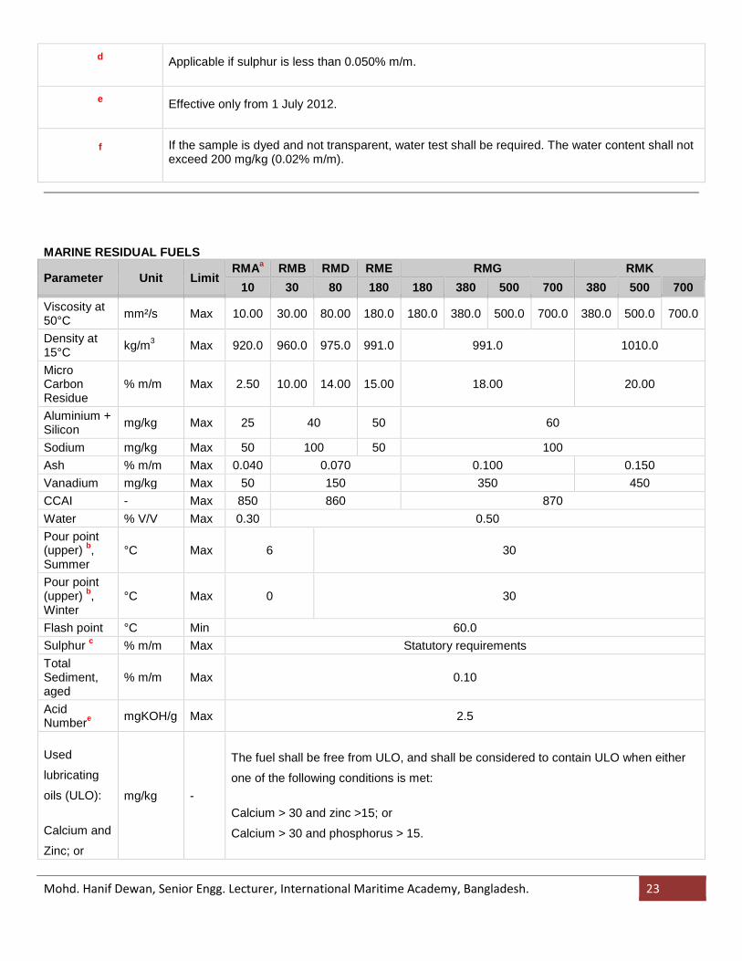
MARINE RESIDUAL FUELS
Parameter Unit LimitRMAa RMB RMD RME RMG RMK
10 30 80 180 180 380 500 700 380 500 700Viscosity at50°C mm²/s Max 10.00 30.00 80.00 180.0 180.0 380.0 500.0 700.0 380.0 500.0 700.0
Density at15°C kg/m3 Max 920.0 960.0 975.0 991.0 991.0 1010.0
MicroCarbonResidue
% m/m Max 2.50 10.00 14.00 15.00 18.00 20.00
Aluminium +Silicon mg/kg Max 25 40 50 60
Sodium mg/kg Max 50 100 50 100Ash % m/m Max 0.040 0.070 0.100 0.150Vanadium mg/kg Max 50 150 350 450CCAI - Max 850 860 870Water % V/V Max 0.30 0.50Pour point(upper) b,Summer
°C Max 6 30
Pour point(upper) b,Winter
°C Max 0 30
Flash point °C Min 60.0Sulphur c % m/m Max Statutory requirementsTotalSediment,aged
% m/m Max 0.10
AcidNumbere mgKOH/g Max 2.5
Used
lubricating
oils (ULO):
Calcium and
Zinc; or
mg/kg -
The fuel shall be free from ULO, and shall be considered to contain ULO when either
one of the following conditions is met:
Calcium > 30 and zinc >15; or
Calcium > 30 and phosphorus > 15.
Mohd. Hanif Dewan, Senior Engg. Lecturer, International Maritime Academy, Bangladesh. 24
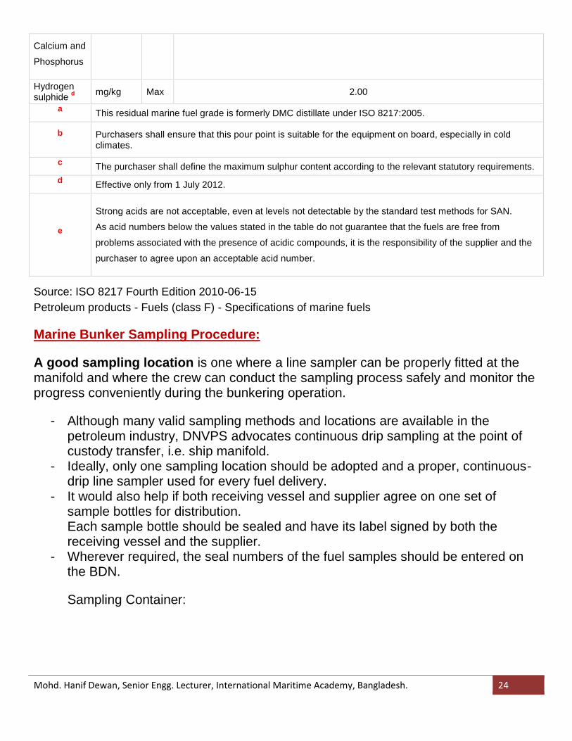
Calcium and
Phosphorus
Hydrogensulphide d mg/kg Max 2.00
a This residual marine fuel grade is formerly DMC distillate under ISO 8217:2005.
b Purchasers shall ensure that this pour point is suitable for the equipment on board, especially in coldclimates.
c The purchaser shall define the maximum sulphur content according to the relevant statutory requirements.d Effective only from 1 July 2012.
e
Strong acids are not acceptable, even at levels not detectable by the standard test methods for SAN.
As acid numbers below the values stated in the table do not guarantee that the fuels are free from
problems associated with the presence of acidic compounds, it is the responsibility of the supplier and the
purchaser to agree upon an acceptable acid number.
Source: ISO 8217 Fourth Edition 2010-06-15Petroleum products - Fuels (class F) - Specifications of marine fuels
Marine Bunker Sampling Procedure:
A good sampling location is one where a line sampler can be properly fitted at themanifold and where the crew can conduct the sampling process safely and monitor theprogress conveniently during the bunkering operation.
- Although many valid sampling methods and locations are available in thepetroleum industry, DNVPS advocates continuous drip sampling at the point ofcustody transfer, i.e. ship manifold.
- Ideally, only one sampling location should be adopted and a proper, continuous-drip line sampler used for every fuel delivery.
- It would also help if both receiving vessel and supplier agree on one set ofsample bottles for distribution.Each sample bottle should be sealed and have its label signed by both thereceiving vessel and the supplier.
- Wherever required, the seal numbers of the fuel samples should be entered onthe BDN.
Sampling Container:
Mohd. Hanif Dewan, Senior Engg. Lecturer, International Maritime Academy, Bangladesh. 25
1. Sampling Device
Procedures for sampling - step 1
Ensure that your vessel has a proper sampling device at the point of CustodyTransfer, which is at the vessel's bunker manifold.
Your sampling device and collection container should be clean and ready for use.Ifyour vessel is not fitted with a proper sampling device, you will not be able to take arepresentative sample. We strongly recommend that you place an order for a DNVPSLine Sampler.
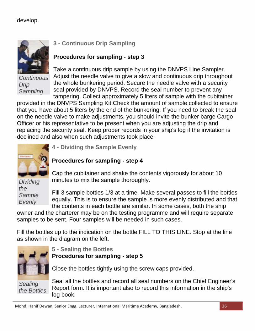
2 - Request to Witness Sampling Form
Procedures for sampling - step 2
Complete a Request to Witness Sampling Form and give the top copyto the suppliers representative. Retain the blue copy for your file.
Invite the supplier's representative to witness the sampling procedures.
If the supplier declines to attend the witnessing of sampling, it is essential that yourecord this fact in the ship's log book at the time as contemporaneous evidence forfuture reference in case there is dispute.
Ensure that full information about the barge, cargo officer, supplier, time, date, andcircumstances etc. are recorded. These records will be important should a dispute
SamplingForm
Mohd. Hanif Dewan, Senior Engg. Lecturer, International Maritime Academy, Bangladesh. 26
develop.
3 - Continuous Drip Sampling
Procedures for sampling - step 3
Take a continuous drip sample by using the DNVPS Line Sampler.Adjust the needle valve to give a slow and continuous drip throughoutthe whole bunkering period. Secure the needle valve with a securityseal provided by DNVPS. Record the seal number to prevent anytampering. Collect approximately 5 liters of sample with the cubitainer
provided in the DNVPS Sampling Kit.Check the amount of sample collected to ensurethat you have about 5 liters by the end of the bunkering. If you need to break the sealon the needle valve to make adjustments, you should invite the bunker barge CargoOfficer or his representative to be present when you are adjusting the drip andreplacing the security seal. Keep proper records in your ship's log if the invitation isdeclined and also when such adjustments took place.
ContinuousDripSampling
4 - Dividing the Sample Evenly
Procedures for sampling - step 4
Cap the cubitainer and shake the contents vigorously for about 10minutes to mix the sample thoroughly.
Fill 3 sample bottles 1/3 at a time. Make several passes to fill the bottlesequally. This is to ensure the sample is more evenly distributed and thatthe contents in each bottle are similar. In some cases, both the ship
owner and the charterer may be on the testing programme and will require separatesamples to be sent. Four samples will be needed in such cases.
Fill the bottles up to the indication on the bottle FILL TO THIS LINE. Stop at the lineas shown in the diagram on the left.
DividingtheSampleEvenly
5 - Sealing the BottlesProcedures for sampling - step 5
Close the bottles tightly using the screw caps provided.
Seal all the bottles and record all seal numbers on the Chief Engineer'sReport form. It is important also to record this information in the ship'slog book.
Sealingthe Bottles
Mohd. Hanif Dewan, Senior Engg. Lecturer, International Maritime Academy, Bangladesh. 27
Complete three (or four) sample bottles labels and sign them in the presence of thesupplier's representative. Do not sign any blank labels for the barge crew under anycircumstances.
Fix a label on each bottle.
Caution: If you are offered a sample by the barge crew and have not witnessedcorrect sampling procedures, please use the rubber stamp provided to indicate a 'Forreceipt only, source unknown' message on the sample label.
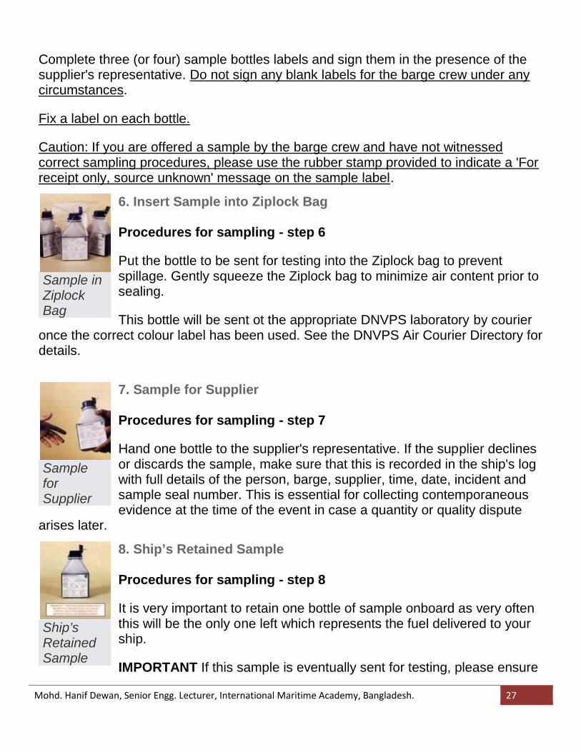
6. Insert Sample into Ziplock Bag
Procedures for sampling - step 6
Put the bottle to be sent for testing into the Ziplock bag to preventspillage. Gently squeeze the Ziplock bag to minimize air content prior tosealing.
This bottle will be sent ot the appropriate DNVPS laboratory by courieronce the correct colour label has been used. See the DNVPS Air Courier Directory fordetails.
Sample inZiplockBag
7. Sample for Supplier
Procedures for sampling - step 7
Hand one bottle to the supplier's representative. If the supplier declinesor discards the sample, make sure that this is recorded in the ship's logwith full details of the person, barge, supplier, time, date, incident andsample seal number. This is essential for collecting contemporaneousevidence at the time of the event in case a quantity or quality dispute
arises later.
SampleforSupplier
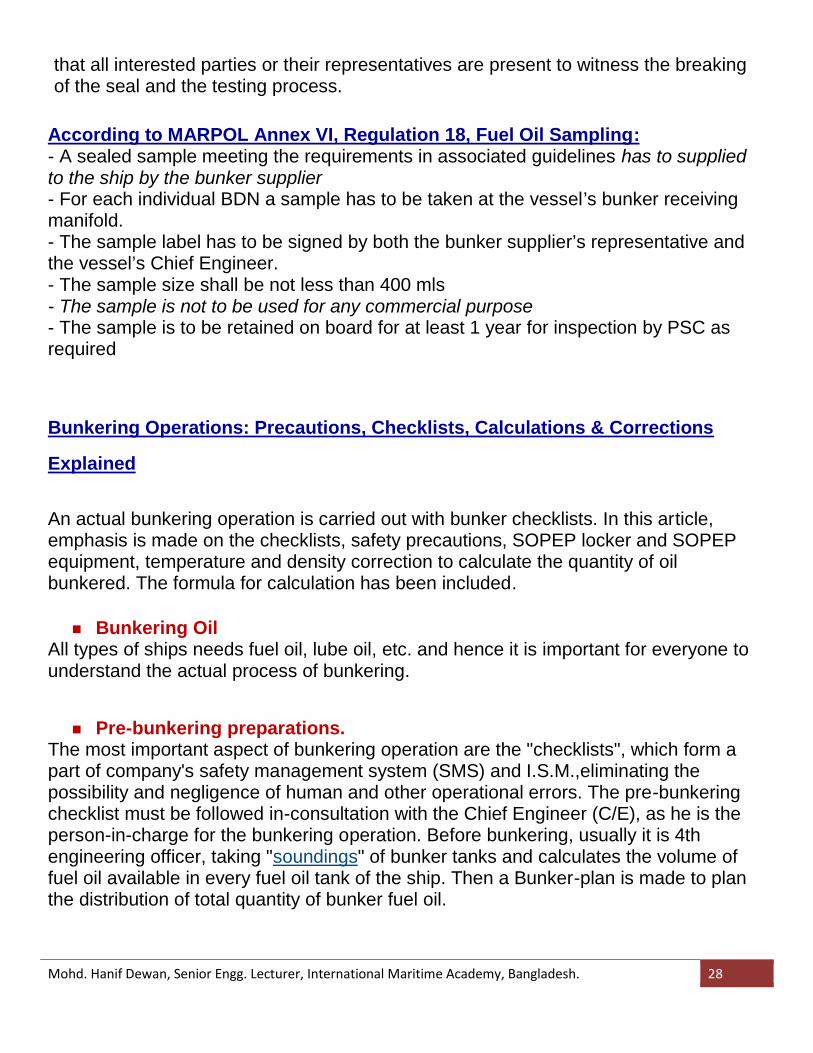
8. Ship’s Retained Sample
Procedures for sampling - step 8
It is very important to retain one bottle of sample onboard as very oftenthis will be the only one left which represents the fuel delivered to yourship.
IMPORTANT If this sample is eventually sent for testing, please ensure
Ship’sRetainedSample
Mohd. Hanif Dewan, Senior Engg. Lecturer, International Maritime Academy, Bangladesh. 28
that all interested parties or their representatives are present to witness the breakingof the seal and the testing process.
According to MARPOL Annex VI, Regulation 18, Fuel Oil Sampling:- A sealed sample meeting the requirements in associated guidelines has to suppliedto the ship by the bunker supplier- For each individual BDN a sample has to be taken at the vessel’s bunker receivingmanifold.- The sample label has to be signed by both the bunker supplier’s representative andthe vessel’s Chief Engineer.- The sample size shall be not less than 400 mls- The sample is not to be used for any commercial purpose- The sample is to be retained on board for at least 1 year for inspection by PSC asrequired
Bunkering Operations: Precautions, Checklists, Calculations & Corrections
Explained
An actual bunkering operation is carried out with bunker checklists. In this article,emphasis is made on the checklists, safety precautions, SOPEP locker and SOPEPequipment, temperature and density correction to calculate the quantity of oilbunkered. The formula for calculation has been included.
Bunkering OilAll types of ships needs fuel oil, lube oil, etc. and hence it is important for everyone tounderstand the actual process of bunkering.
Pre-bunkering preparations.The most important aspect of bunkering operation are the "checklists", which form apart of company's safety management system (SMS) and I.S.M.,eliminating thepossibility and negligence of human and other operational errors. The pre-bunkeringchecklist must be followed in-consultation with the Chief Engineer (C/E), as he is theperson-in-charge for the bunkering operation. Before bunkering, usually it is 4thengineering officer, taking "soundings" of bunker tanks and calculates the volume offuel oil available in every fuel oil tank of the ship. Then a Bunker-plan is made to planthe distribution of total quantity of bunker fuel oil.
Mohd. Hanif Dewan, Senior Engg. Lecturer, International Maritime Academy, Bangladesh. 29
Bunker Procurement
Ordering of Bunker oil:The ship Managers (superintendents) monitor the performance of a fleet of ships. Forexample, on owning a car, we tend to keep a check on its fuel consumption widelycalled as "mileage." It is the distance travelled by the vehicle for a unit volume of fuelused. In the same way, as the ship consumes humungous quantity of fuel, whosecosts are forming the major part of ship's operation. Managers tend to keep a check onit. This is measured in terms of specific fuel oil consumption of the main propulsionengine.
Upon knowing the fuel oil consumption for a day and the next voyage plan, the quantityof fuel oil required is calculated and compared with the available bunker tank capacity.A requisition is placed through the C/E and Master of the vessel to the Managers. Therequisition is processed and evaluated for the quality and quantity of fuel to be suppliedfor the particular ship. Planning is done for the delivery of bunker at a particular portwhere the oil is available at a comparitive lesser cost. On taking all these aspects intoconsideration, the Managers, deliver bunker to the vessel. Upon receiving the bunker,a sample collected during bunkering operation is sent for lab analysis to confirm thedelivered oil meets the required standard for the safe and efficient operation of theauxiliary engines & main propulsion engine.
Pre-Bunker Checklist1. State of adjacent waters noticed2. Vessel properly secured to dock3. Check suppliers product corresponds to ordered product4. Agree quantity to be supplied5. Check valves open6. Day tanks full and supply valves closed7. Warning signs in position e.g. No Smoking8. SOPEP plan available9. Clean up material in place10. Oil Boom in place11. Foam fire extinguisher placed at bunker station12. Alfa Laval and transfer pumps off
Mohd. Hanif Dewan, Senior Engg. Lecturer, International Maritime Academy, Bangladesh. 30
13. Fuel tank supply valves open14. Agree stop/start signals between vessel and barge/truck15. Bravo flag flying/red light showing16. Agree pumping/transfer rate17. Agree emergency shut down procedure18. Specification sheet received19. Check hose and couplings are secure and in good order20. Fuel nozzle and hose secured to vessel21. Check barge/truck meters Reading:22. Check on board meters Reading:23. Bunker Valve open24. Unused manifold connections blanked off25. Master informed26. Signal pumping to commence
The above checklist has to be completely filled religiously by both the ship & bargepersonnel.
SOPEP equipmentsAt the bunker manifold and wherever necessary, as per the ships SOPEP plan, theSOPEP equipments should be kept in immediate readiness in order to avoid oilspill/pollution during bunkering operation.SOPEP- Shipboard Oil Pollution Emergency Plan.The SOPEP Locker must have minimum of the below specified items:1. Absorbent roll2. Absorbent pads3. Absorbent granules4. Absorbent materials5. Brooms6. Shovels7. Mops
Mohd. Hanif Dewan, Senior Engg. Lecturer, International Maritime Academy, Bangladesh. 31
8. Scoops9. Empty receptacles (200 ltrs capacity)10. Portable air driven pumps11. Oil boom12. Oil spill dispersants.These items must be stowed in an easily accessible locker, clearly marked, and is tobe brought on deck ready for immediate use, prior to all oil transfer operations.
During Bunkering Procedures - Checklist1. Witness taking and sealing of 2 representative product samples2. Monitor fuel connections for leaks fuel flow and control tank levels3. Change over of tanks whenever necessary.4. Checking the rate at which bunkers are received.5. Checking the tightness/slackness of mooring ropes.6. Checking trim/list of the bunker barge & the ship.7. Continuous monitoring/look outs for the vessel's position(when at anchor).During bunkering, the above checklist must be filled up and continuous monitoring ofthe above secified items are required till the bunkering operation is complete.
After Bunkering Procedures:On completion of the bunkering operations, with the ship-barge co-ordination, the lineshould be blown with air to make sure the line is not filled with oil. The after-bunkerchecklist is followed.
After Bunker Checklist1. Bunker Valve closed2. Disconnect hose (drain before disconnecting)3. Check barge/truck meter Reading:4. Check ships meter Reading:5. Sign Bunker Delivery Receipt BDR No.:(Bunker Delivery Report/Note).6. Retain BDR with product sample
Mohd. Hanif Dewan, Senior Engg. Lecturer, International Maritime Academy, Bangladesh. 32
7. SOPEP plan returned to bridge8. Clean up gear stowed / Oil boom returned9. Bravo Flag/Red light stowed/switched off10. Remove and pack away warning/safety signs11. Foam fire extinguisher placed back in correct location12. Complete Oil Record Book13. Master informed of completion14. Confirm in Oil Record Book Bunkering checklist completed
Quantity Calculation & Temperature-Density Correction:After bunkering of various fuel oil tanks, the quantity in each bunkered tank must becalculated to cross-check whether the received quantity of oil matches the requisition.For calculating the quantity, "sounding" of the tanks which are "bunkered" must betaken. The "Density" of the fuel oil supplied vary from place to place. It also varies withthe temperature. As a thumb rule, the density of fuel oil decreases with increase intemperature. So, when the oil is supplied at a higher temperature, then the volume ofoil supplied is less than what is supplied at lesser temperature.
Oil Temperature ----------------------------Density ------------------------------- Volume Of OilSuppliedIncreases--------------------------------------Decreases------------------------------------LesserDecreases--------------------------------- ---Increases -------------------------------------More
Also the formula which is generally used for temperature-density correction is asfollows:MT = (Temperature Corrected density * Actual Sounded Volume).Temperature Corrected Density can be calculated with the under-mentioned fomula:Temperature corrected Density = Density of Fuel Oil @ 15 degree Celsius * [1- {(t1-15)* 0.00064}]Where,t1 stands for temperature of oil in bunker tanks in degree Celsius, 0.00064 is thecorrection factor,volume of oil in m^3 (actual sounded volume), is obtained from the sounding table.
Mohd. Hanif Dewan, Senior Engg. Lecturer, International Maritime Academy, Bangladesh. 33
Safeties of bunkering:General Safeties During Bunkering: SOPEP locker, Emergency shut-down arrangements, Bunker line over-flow arrangements to overflow tank with audible & visual alarm, Relief valve in the bunker line, Containment trays. Consistent & Continuous look outs.
Thus bunkering operation is directly related to "MARPOL" annexes, i.e annex 1 andannex 6. When oil is spilled it causes marine pollution under annex 1. When thebunkered oil doesn't meet certain specifications, it causes pollution of air which comesunder annex 6.
MARPOL regulations regarding bunkering:Regulation 18 - Fuel Oil quality. “Fuel oil shall be blends of hydrocarbons derived from petroleum refining” “Fuel oil shall be free from inorganic acid” “Fuel oil shall not include any added substance or chemical waste which either:
o Jeopardises the safety of ships or adversely affects the performance of themachinery, or
o Is harmful to personnel, oro Contributes overall to additional air pollution”
Bunker Delivery Note (BDN):- Becomes a Statutory document- Must be kept on board for 3 years for inspection and a copy may be taken for furtherexamination by PSC.- Must contain all data required by Appendix V- Name and IMO number of vessel Port- Date of Commencement of delivery- Details of fuel oil supplier- Product name, quantity , Density at 15 0C and Sulphur content % m/m- A declaration that fuel supplied meets Regulation 14 and 18 requirements

Mohd. Hanif Dewan, Senior Engg. Lecturer, International Maritime Academy, Bangladesh. 34
Shipboard Procedures for BDN and Samples Adequate bunker manifold location for sampler attachment External safe storage location for samples for 1 year period Log book for sample retention and custody transfer Safe storage for BDNs and other documents relating to bunkering onboard Port/Flag State Control Guidelines Proposed Guidelines from FSI 13 for MEPC 53 approval. Initial inspections and Primary survey parameters – then “Clear Grounds” for in-
depth inspections “In depth” inspection parameters
Any Question?Thank you!
Related Documents