Project Report frequency generator EITF40 Digital Project student: Robert Walther ([email protected]) supervisor: Bertil Lindvall 1

Welcome message from author
This document is posted to help you gain knowledge. Please leave a comment to let me know what you think about it! Share it to your friends and learn new things together.
Transcript
Project Reportfrequency generator
EITF40 Digital Project
student: Robert Walther ([email protected])supervisor: Bertil Lindvall
1
Content1. Introduction...............................................................................................................32. Generator requirements.............................................................................................33. Realization.................................................................................................................4
3.1 Hardware.............................................................................................................43.2 Software...............................................................................................................5
4. Testing........................................................................................................................74.1 Problems and limitations.....................................................................................7
5. Conclusion...............................................................................................................116. Source code..............................................................................................................117. References ..............................................................................................................24
2
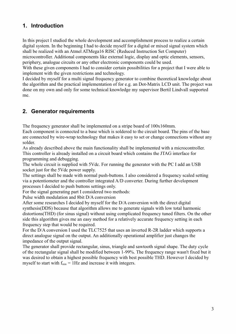
1. Introduction
In this project I studied the whole development and accomplishment process to realize a certain digital system. In the beginning I had to decide myself for a digital or mixed signal system which shall be realized with an Atmel ATMega16 RISC (Reduced Instruction Set Computer) microcontroller. Additional components like external logic, display and optic elements, sensors, periphery, analogue circuits or any other electronic components could be used.With these given components I had to consider certain possibilities for a project that I were able to implement with the given restrictions and technology.I decided by myself for a multi signal frequency generator to combine theoretical knowledge about the algorithm and the practical implementation of for e.g. an Dot-Matrix LCD unit. The project was done on my own and only for some technical knowledge my supervisor Bertil Lindvall supported me.
2. Generator requirements
The frequency generator shall be implemented on a stripe board of 100x160mm.Each component is connected to a base which is soldered to the circuit board. The pins of the base are connected by wire-wrap technology that makes it easy to set or change connections without any solder.As already described above the main functionality shall be implemented with a microcontroller.This controller is already installed on a circuit board which contains the JTAG interface for programming and debugging.The whole circuit is supplied with 5Vdc. For running the generator with the PC I add an USB socket just for the 5Vdc power supply.The settings shall be made with normal push-buttons. I also considered a frequency scaled setting via a potentiometer and the controller integrated A/D converter. During further development processes I decided to push buttons settings only.For the signal generating part I considered two methods: Pulse width modulation and 8bit D/A conversionAfter some researches I decided by myself for the D/A conversion with the direct digital synthesis(DDS) because that algorithm allows me to generate signals with low total harmonic distortions(THD) (for sinus signal) without using complicated frequency tuned filters. On the other side this algorithm gives me an easy method for a relatively accurate frequency setting in each frequency step that would be required. For the D/A conversion I used the TLC7525 that uses an inverted R-2R ladder which supports a direct analogue signal on the output. An additionally operational amplifier just changes the impedance of the output signal. The generator shall provide rectangular, sinus, triangle and sawtooth signal shape. The duty cycle of the rectangular signal shall be modified between 1-99%. The frequency range wasn't fixed but it was desired to obtain a highest possible frequency with best possible THD. However I decided by myself to start with fmin = 1Hz and increase it with integers.
3
3. Realization
3.1 HardwareWith all these requirements from point 2 I develop a schematic with eagle layout editor as follow:
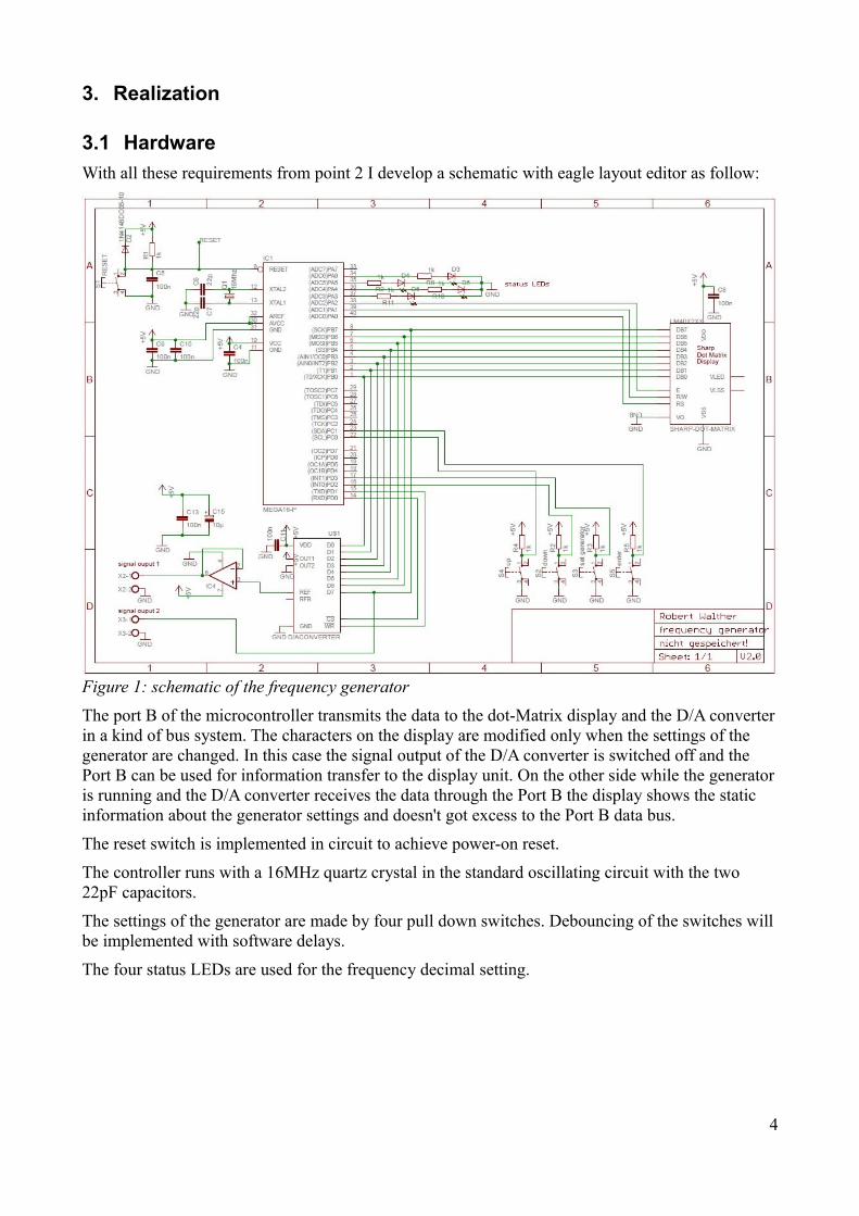
Figure 1: schematic of the frequency generator
The port B of the microcontroller transmits the data to the dot-Matrix display and the D/A converter in a kind of bus system. The characters on the display are modified only when the settings of the generator are changed. In this case the signal output of the D/A converter is switched off and the Port B can be used for information transfer to the display unit. On the other side while the generator is running and the D/A converter receives the data through the Port B the display shows the static information about the generator settings and doesn't got excess to the Port B data bus.
The reset switch is implemented in circuit to achieve power-on reset.
The controller runs with a 16MHz quartz crystal in the standard oscillating circuit with the two 22pF capacitors.
The settings of the generator are made by four pull down switches. Debouncing of the switches will be implemented with software delays.
The four status LEDs are used for the frequency decimal setting.
4

Figure 2: wire wrap connections on the bottom side of the generator circuit
3.2 SoftwareThe development of the program is the most time consuming part of the project work. In the beginning I studied the data sheet of the AT Mega16 microcontroller and did some research how to implement certain functionalities.
The program is written in C with the integrated development environment AVR studio 4.
The fundamental program chain:
-After switch on the power supply or push 'reset' the display shows generator abbreviations and sets the generator to default values. This process can be interrupted by pressing 'set generator' to set all parameters of the generator by running an interrupt subprogram. In the first step the signal type can be changed by 'up'-button. After pressing 'enter' the lowest frequency decimal can be set with 'up' or 'down'. Pressing 'enter' selects the next higher frequency decimal up to the 5th frequency decimal. Integer frequency values until 65535 can be set. If rectangular signal is selected the duty cycle can be set in analogue way like the frequency between 1 and 99%. Finishing with 'enter' executes the generator routine with the set parameters. For new frequency setting 'set generator' must be pushed.
The signal generation routine through DDS can be described as follow:
256 function values with an accuracy of 8bit are stored in a lookup table vector for each signal type. Therefore the function values varies between 0 and 255. A variable 'number' with a huge domain is used to represent the certain phase of the signal function. If this variable is normalized to the
5

amount of phase steps of the signal lookup table vector it represents a pointer to a certain phase position of the signal. Normalization: 'number'/(2bitlength(number)-2bitlenght(lookup table)).According the required frequency a certain value 'table_add' is added to the phase representing variable 'number' in a runtime-stable loop. In this loop the normalized 'number' points each loop-sweep on a certain function value. The microcontroller sends this value to the D/A converter through the 8bit Port interface.while(1)
{PORTB = table[number/16777216]; // normalization
number=number+table_add; // phase increasing}
// loop for DDS algorithm
The bigger the domain of 'number' the more accurate the frequency and the lower the maximum possible frequencyare (at a certain THD given). It is obvious that the processor clock speed is also direct proportional to the generator frequency. Another detailed point is that with a higher domain(16, 32 or 64 bit) of 'number' the microcontroller needs more steps to process the arithmetic functions with the 8bit limited processor RISC-architecture.I decided by myself for a 32bit variable 'number'. The frequency accuracy is much higher then in the 16bit case while on the other side the maximum frequency is still high enough.
The following part describes how to determine the 'table_add' value:
First of all I have to determine the amounts of processor clocks 'n' that are needed to run the DDS algorithm in the while(1)-loop with the 32bit variables. The required signal frequency is set to 1Hz and the output period time 't' of the signal is measured by an oscilloscope. 'table_add' can be set to any value.
16MHz/2^32*table_add/n=t => n=48 => for t=1s : table_add=2^32/16MHz*n=12884.9
With a required output frequency 'f' 'table_add' is set to f*table_add.
The whole microcontroller program contains four source files:
- display.c contains all functions that are needed to communicate with the dot-matrix LCD and to print characters and numbers. A certain framework is implemented to show the fixed generator parameters like signal type, frequency and duty-cycle.
- generator_setting.c is executed through an interrupt INT1 routine by 'set generator'. A fixed program flow is used to request all information from the user that you can set in the controller(see fundamental program chain from above)
- lookup_tables.c is responsible to save the appropriate lookup table vector in the vector 'table' that the DDS algorithm accesses to. The sinus and triangle table is calculated “offline”(with matlab) and stored in a fixed vector. The rectangular and sawtooth tables are calculated after the function 'generator_settings'. To avoid extra processes in the DDS loop through an assortment of the appropriate lookup table an empty vector 'table' is used.
- main.c coordinated the certain generator functions and runs the DDS loop.
6
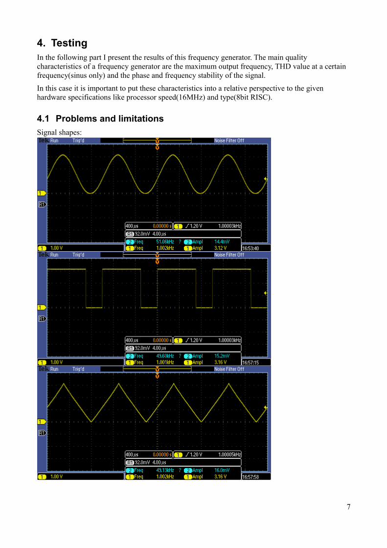
4. TestingIn the following part I present the results of this frequency generator. The main quality characteristics of a frequency generator are the maximum output frequency, THD value at a certain frequency(sinus only) and the phase and frequency stability of the signal.
In this case it is important to put these characteristics into a relative perspective to the given hardware specifications like processor speed(16MHz) and type(8bit RISC).
4.1 Problems and limitationsSignal shapes:
7
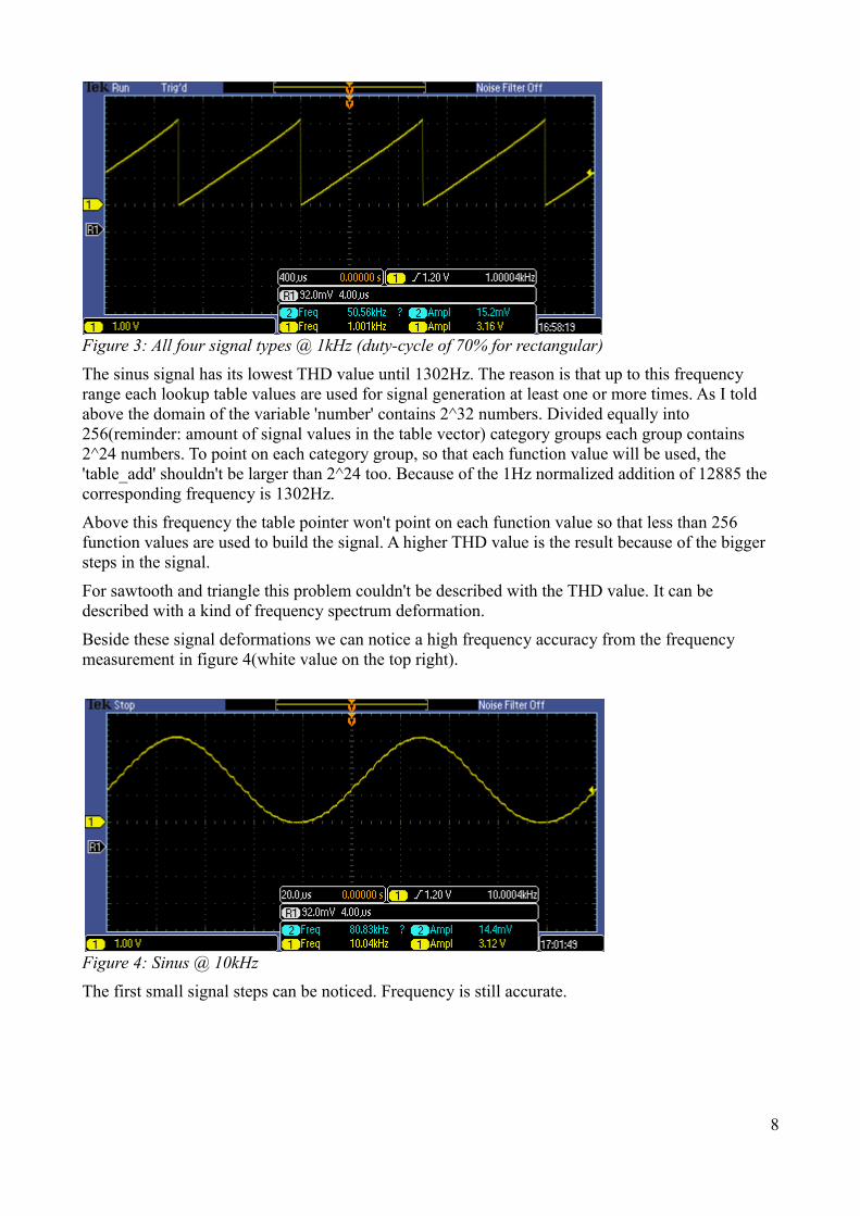
Figure 3: All four signal types @ 1kHz (duty-cycle of 70% for rectangular)The sinus signal has its lowest THD value until 1302Hz. The reason is that up to this frequency range each lookup table values are used for signal generation at least one or more times. As I told above the domain of the variable 'number' contains 2^32 numbers. Divided equally into 256(reminder: amount of signal values in the table vector) category groups each group contains 2^24 numbers. To point on each category group, so that each function value will be used, the 'table_add' shouldn't be larger than 2^24 too. Because of the 1Hz normalized addition of 12885 the corresponding frequency is 1302Hz.
Above this frequency the table pointer won't point on each function value so that less than 256 function values are used to build the signal. A higher THD value is the result because of the bigger steps in the signal.
For sawtooth and triangle this problem couldn't be described with the THD value. It can be described with a kind of frequency spectrum deformation.
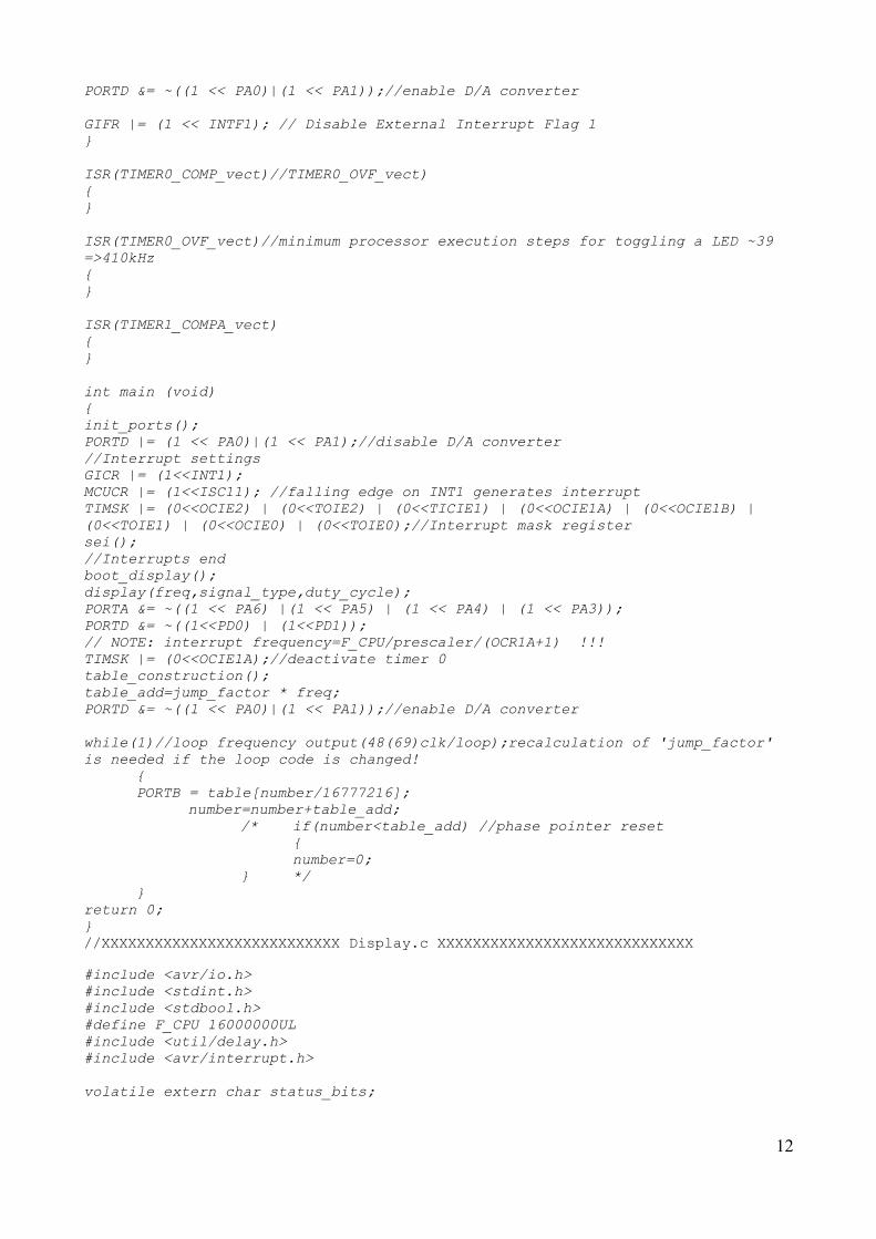
Beside these signal deformations we can notice a high frequency accuracy from the frequency measurement in figure 4(white value on the top right).
Figure 4: Sinus @ 10kHzThe first small signal steps can be noticed. Frequency is still accurate.
8

Figure 5: Sinus @ 25kHz
Figure 6: Sinus @ 35kHz
Figure 7: Sinus @ 65kHzAt 65 kHz each period contains only ~5 values from the sinus table(2^32/65kHz/12885). From one value to another value we can notice a big step which grows exponentially because of the R C characteristic of the D/A converter.
9

Figure 8: Rectangular @ 10kHzAnother problem that we can notice the best with the rectangular signal is the phase disturbance.
Over 1302 Hz not every function value(in the rectangular case just 0 and 255 respective to the duty cycle) is used and after one period one more function values are missing.
In figure 8 we can see relative small phase disturbances at 10kHz. 7 till 8 function values are missing in the beginning so that the signal starts different each cycle.
Figure 8: Rectangular @ 30kHzAt 30kHz ~23 values are missing with every new period which will result in a phase error up to 9%(23/256(total values)).
This phase error can be easily compensated(code in bold) with a phase reset each period:
while(1){PORTB = table[number/16777216];
number=number+table_add;if(number<table_add){number=0;}
}This compensation would decrease the frequency accuracy in higher frequencies in the same way
10

like the phase value without compensation. Additionally there are more process steps in the DDS loop which would reduce the loop speed.
5. ConclusionFinally this frequency generator offers a constant signal quality until f=1302 Hz. For most of the purposes the signal quality is good enough until 10kHz. Depended on the signal requirements even for some purposes signal qualities above 10kHz are sufficient. With this project work I got the possibility to implement a DDS synthesizer on an ordinary microcontroller. In practical signal generator applications it is common to use complete DDS synthesizer devices which architecture is developed for the DDS algorithm. These DDS chips can provide signal frequencies up to the MHz range.
6. Source code//XXXXXXXXXXXXXXXXXXXXXXXXXXX Main.c XXXXXXXXXXXXXXXXXXXXXXXXXXXXX#include <avr/io.h> #include <stdint.h>#include <stdbool.h>#define F_CPU 16000000UL #include <util/delay.h>#define ROUND_INT(d) ( (int) ((d) + ((d) > 0 ? 0.5 : -0.5)) )#include <avr/interrupt.h> #include "display.h"#include "lookup_tables.h"#include "generator_setting.h"
volatile extern uint32_t freq=0;volatile extern char signal_type=0x01;volatile extern short int duty_cycle=50;volatile extern char status_bits=0x00;char timer_comp_a=0;//set to one if ISR TIMER1_COMPA_vect is activevolatile extern uint32_t number=0xFFFFFFFF;// volatile avoids the optimization in changing these variables in a while(1) loopvolatile extern uint32_t table_add=0;volatile extern uint32_t jump_factor=12885;
/*the jump_factor results from following calculation:The while(1) loop in 'main' needs(with this actual program code) 48 processor clocks. 'number' has got2^32 numbers. The time until 'number' got a overflow calculates as follow: t=F_CPU/2^32/48*jump_factorfor t=1s =>jump_factor=12885*/
ISR(INT1_vect)//ENTER generator_setting mode{TIMSK |= (0<<OCIE1A);//deactivate timer 1APORTB=0x00;//Reset D/A outputsPORTD |= (1 << PA0)|(1 << PA1);//disable D/A converterPORTD &= ~(1 << PA7);//reset rec output status_bits |=(1 << 0);PORTA &= ~((1 << PA6) |(1 << PA5) | (1 << PA4) | (1 << PA3));generator_settings();//calculation of the 'table' vectortable_construction();
table_add=jump_factor * freq;
11
PORTD &= ~((1 << PA0)|(1 << PA1));//enable D/A converter
GIFR |= (1 << INTF1); // Disable External Interrupt Flag 1}
ISR(TIMER0_COMP_vect)//TIMER0_OVF_vect){}
ISR(TIMER0_OVF_vect)//minimum processor execution steps for toggling a LED ~39 =>410kHz {}
ISR(TIMER1_COMPA_vect){}
int main (void) { init_ports();PORTD |= (1 << PA0)|(1 << PA1);//disable D/A converter//Interrupt settingsGICR |= (1<<INT1); MCUCR |= (1<<ISC11); //falling edge on INT1 generates interruptTIMSK |= (0<<OCIE2) | (0<<TOIE2) | (0<<TICIE1) | (0<<OCIE1A) | (0<<OCIE1B) | (0<<TOIE1) | (0<<OCIE0) | (0<<TOIE0);//Interrupt mask registersei();//Interrupts endboot_display(); display(freq,signal_type,duty_cycle);PORTA &= ~((1 << PA6) |(1 << PA5) | (1 << PA4) | (1 << PA3));PORTD &= ~((1<<PD0) | (1<<PD1));// NOTE: interrupt frequency=F_CPU/prescaler/(OCR1A+1) !!!TIMSK |= (0<<OCIE1A);//deactivate timer 0table_construction();table_add=jump_factor * freq;PORTD &= ~((1 << PA0)|(1 << PA1));//enable D/A converter
while(1)//loop frequency output(48(69)clk/loop);recalculation of 'jump_factor' is needed if the loop code is changed!
{PORTB = table[number/16777216];
number=number+table_add;/* if(number<table_add) //phase pointer reset
{number=0;
} */}
return 0; }//XXXXXXXXXXXXXXXXXXXXXXXXXXX Display.c XXXXXXXXXXXXXXXXXXXXXXXXXXXXX
#include <avr/io.h> #include <stdint.h>#include <stdbool.h>#define F_CPU 16000000UL #include <util/delay.h>#include <avr/interrupt.h>
volatile extern char status_bits;
12
void display_instruction(char ins){ //write an instruction to the display
_delay_ms(2);PORTB =ins;PORTA &= ~((1 << PA2) | (1 << PA1) | (1 << PA0));PORTA |= (1<<PA2); //one clk for EPORTA &= ~(1 << PA2);return;
}
void write_char(char c){ _delay_ms(2);
//write an characterPORTB = c;//set the RS bit to 1 for writing to data regPORTA &= ~((1 << PA2) | (1 << PA1) | (1 << PA0)); PORTA |= (1<<PA0);//set RSPORTA |= (1<<PA2); //one clk for EPORTA &= ~((1 << PA2));return;
}
void display_reset(){
display_instruction(0b00000001); //clear displayreturn;
}
void cursor_reset(){
display_instruction(0b00001100); //set display on,cursor off,blink offdisplay_instruction(0b00000010); //reset cursor positionreturn;
}
void cursor_set(char position){
display_instruction(position+0b10000000);display_instruction(0b00001111); //set display on,cursor on,blink onreturn;
}
void write_num(uint16_t num,bool print_freq) //print frequency or duty cycle{uint16_t temp=0;uint16_t x=num;
if(num>=10000){
temp=x/10000;write_char(temp+0b00110000);x=x-temp*10000;
}else if(print_freq==true && !(num>99999)){
write_char(' ');}
if(num>=1000){
temp=x/1000;
13

write_char(temp+0b00110000);x=x-temp*1000;
}else if(print_freq==true && !(num>9999)){
write_char(' ');}
if(num>=100){
temp=x/100;write_char(temp+0b00110000);x=x-temp*100;
}else if(print_freq==true && !(num>999)){
write_char(' ');}
if(num>=10){
temp=x/10;write_char(temp+0b00110000);x=x-temp*10;
}else if(!(num>99)){
write_char(' ');}
write_char(x+0b00110000);
return;}
void boot_display(){
display_instruction(0b00110000); //function set:8bit,singel linedisplay_instruction(0b00001100); //set display on,cursor off,blink offdisplay_instruction(0b00000110); //set increment,shift off
display_reset();write_char('f');write_char('r');write_char('e');write_char('q');write_char('.');write_char(' ');write_char('g');write_char('e');write_char('n');write_char('e');write_char('r');write_char('a');write_char('t');write_char('o');write_char('r');_delay_ms(2000);if(status_bits & (1<<0))//leave now if INT1 is active{return;
14
}
display_reset();write_char('r');write_char('e');write_char('c');write_char('=');write_char('r');write_char('e');write_char('c');write_char('t');write_char('a');write_char('n');write_char('g');write_char('u');write_char('l');write_char('a');write_char('r');_delay_ms(1000);if(status_bits & (1<<0))//leave now if INT1 is active{return;}
display_reset();write_char('s');write_char('i');write_char('n');write_char('=');write_char('s');write_char('i');write_char('n');write_char('u');write_char('s');_delay_ms(1000);if(status_bits & (1<<0))//leave now if INT1 is active{return;}
display_reset();write_char('t');write_char('r');write_char('i');write_char('=');write_char('t');write_char('r');write_char('i');write_char('a');write_char('n');write_char('g');write_char('l');write_char('e');_delay_ms(1000);if(status_bits & (1<<0))//leave now if INT1 is active{return;}
display_reset();write_char('s');
15
write_char('a');write_char('w');write_char('=');write_char('s');write_char('a');write_char('w');write_char('t');write_char('o');write_char('o');write_char('t');write_char('h');_delay_ms(1000);if(status_bits & (1<<0))//leave now if INT1 is active{return;}
display_reset();write_char('f');write_char('=');write_char('f');write_char('r');write_char('e');write_char('q');write_char('u');write_char('e');write_char('n');write_char('c');write_char('y');write_char('(');write_char('H');write_char('z');write_char(')');_delay_ms(1000);if(status_bits & (1<<0))//leave now if INT1 is active{return;}
display_reset();write_char('d');write_char('=');write_char('d');write_char('u');write_char('t');write_char('y');write_char(' ');write_char('c');write_char('y');write_char('c');write_char('l');write_char('e');write_char('(');write_char('%');write_char(')');_delay_ms(1000);
return;}
void display(uint32_t freq,char signal_type,short int duty_cycle) // general printing function
16

{bool print_freq=true;cursor_reset();display_reset();
if(signal_type==0b00000000)//sinus{write_char('s');write_char('i');write_char('n');write_char(' ');}if(signal_type==0b00000001)//rectangular{write_char('r');write_char('e');write_char('c');write_char(' ');}if(signal_type==0b00000010)//triangle{write_char('t');write_char('r');write_char('i');write_char(' ');}if(signal_type==0b00000011)//sawtooth{write_char('s');write_char('a');write_char('w');write_char(' ');}write_char('f');write_char(':');write_num(freq,print_freq);write_char(' ');if(signal_type==0b00000001)//rectangular{print_freq=false;write_char('d');write_char(':');write_num(duty_cycle,print_freq);}
return;}//XXXXXXXXXXXXXXXXXXXXXXXXXXX generator_setting XXXXXXXXXXXXXXXXXXXXXXXXXXXXX#include <avr/io.h> #include <stdint.h>#include <stdbool.h>#define F_CPU 16000000UL #include <util/delay.h>#include <avr/interrupt.h>
volatile extern uint32_t freq;volatile extern char signal_type;volatile extern short int duty_cycle;volatile extern char status_bits;
void init_ports(){
17
DDRA = 0b01111111; DDRB = 0b11111111;DDRC = 0b00000000;DDRD = 0b10000011;
}
void generator_settings(){display(freq,signal_type,duty_cycle);/////////////////SIGNAL TYPE select_///////////////////////////////while(PINC & (1<<PINC1))//Enter button pressed leaves
{cursor_set(0x00);if(!(PINC & (1<<PINC0))){cursor_reset();signal_type++;
if(signal_type==0b00000100){signal_type=0x00;}
display(freq,signal_type,duty_cycle);_delay_ms(200);}
}_delay_ms(500);/////////////////Frequency select_///////////////////////////////while(PINC & (1<<PINC1))//Enter button pressed leaves
{cursor_set(0x04);if(!(PINC & (1<<PINC0))){
if(freq>=65526){freq=0;}else {freq++;}
display(freq,signal_type,duty_cycle);_delay_ms(150);}
if(!(PIND & (1<<PIND2))){
if(freq<=9){freq=0;}else {freq--;}
display(freq,signal_type,duty_cycle);_delay_ms(150);}
}
_delay_ms(300);PORTA &= ~((1 << PA6) |(1 << PA5) | (1 << PA4) | (1 << PA3));
18

PORTA |= (1 << PA6);
while(PINC & (1<<PINC1))//Enter button pressed leaves{
cursor_set(0x04);if(!(PINC & (1<<PINC0))){
if(freq>=65526){freq=0;}else {freq=freq+10;}
display(freq,signal_type,duty_cycle);_delay_ms(150);}
if(!(PIND & (1<<PIND2))){
if(freq<=9){freq=0;}else {freq=freq-10;}
display(freq,signal_type,duty_cycle);_delay_ms(150);}
}
_delay_ms(300);PORTA &= ~((1 << PA6) |(1 << PA5) | (1 << PA4) | (1 << PA3));PORTA |= (1 << PA5);
while(PINC & (1<<PINC1))//Enter button pressed leaves{
cursor_set(0x04);if(!(PINC & (1<<PINC0))){
if(freq>=65436){freq=0;}else {freq=freq+100;}
display(freq,signal_type,duty_cycle);_delay_ms(150);}
if(!(PIND & (1<<PIND2))){
if(freq<=99){freq=0;
19
}else {freq=freq-100;}
display(freq,signal_type,duty_cycle);_delay_ms(150);}
}
_delay_ms(300);PORTA &= ~((1 << PA6) |(1 << PA5) | (1 << PA4) | (1 << PA3));PORTA |= (1 << PA4);
while(PINC & (1<<PINC1))//Enter button pressed leaves{
cursor_set(0x04);if(!(PINC & (1<<PINC0))){
if(freq>=64536){freq=0;}else {freq=freq+1000;}
display(freq,signal_type,duty_cycle);_delay_ms(150);}
if(!(PIND & (1<<PIND2))){
if(freq<=999){freq=0;}else {freq=freq-1000;}
display(freq,signal_type,duty_cycle);_delay_ms(150);}
}
_delay_ms(500);PORTA &= ~((1 << PA6) |(1 << PA5) | (1 << PA4) | (1 << PA3));PORTA |= (1 << PA3);
while(PINC & (1<<PINC1))//Enter button pressed leaves{
cursor_set(0x04);if(!(PINC & (1<<PINC0))){
if(freq>=55536){freq=0;}else {
20
freq=freq+10000;}
display(freq,signal_type,duty_cycle);_delay_ms(150);}
if(!(PIND & (1<<PIND2))){
if(freq<=9999){freq=0;}else {freq=freq-10000;}
display(freq,signal_type,duty_cycle);_delay_ms(150);}
}PORTA &= ~((1 << PA6) |(1 << PA5) | (1 << PA4) | (1 << PA3));
_delay_ms(300);/////////////////DUTY CYCLE select///////////////////////////////if(signal_type==0b0000001){
while(PINC & (1<<PINC1))//Enter button pressed leaves{
cursor_set(0x0C);
if(!(PINC & (1<<PINC0))){duty_cycle++;
if(duty_cycle==100){duty_cycle=1;}
display(freq,signal_type,duty_cycle);_delay_ms(120);}
if(!(PIND & (1<<PIND2))){duty_cycle--;if(duty_cycle==0)
{duty_cycle=99;}
display(freq,signal_type,duty_cycle);_delay_ms(120);}
}}display(freq,signal_type,duty_cycle);return;}
//XXXXXXXXXXXXXXXXXXXXXXXXXXX lookup_tables XXXXXXXXXXXXXXXXXXXXXXXXXXXXX#include <avr/io.h>
21

#include <stdint.h>#include <stdbool.h>#define F_CPU 16000000UL #include <util/delay.h>#include <avr/interrupt.h>
volatile extern uint32_t freq;volatile extern char signal_type;volatile extern short int duty_cycle;volatile extern char status_bits;uint8_t i=0;volatile extern uint32_t table_add;volatile extern uint32_t jump_factor;
volatile extern uint8_t table[256]={0x00,0x00,0x00,0x00,0x00,0x00,0x00,0x00,0x00,0x00,0x00,0x00,0x00,0x00,0x00,0x00,0x00,0x00,0x00,0x00,0x00,0x00,0x00,0x00,0x00,0x00,0x00,0x00,0x00,0x00,0x00,0x00,0x00,0x00,0x00,0x00,0x00,0x00,0x00,0x00,0x00,0x00,0x00,0x00,0x00,0x00,0x00,0x00,0x00,0x00,0x00,0x00,0x00,0x00,0x00,0x00,0x00,0x00,0x00,0x00,0x00,0x00,0x00,0x00,0x00,0x00,0x00,0x00,0x00,0x00,0x00,0x00,0x00,0x00,0x00,0x00,0x00,0x00,0x00,0x00,0x00,0x00,0x00,0x00,0x00,0x00,0x00,0x00,0x00,0x00,0x00,0x00,0x00,0x00,0x00,0x00,0x00,0x00,0x00,0x00,0x00,0x00,0x00,0x00,0x00,0x00,0x00,0x00,0x00,0x00,0x00,0x00,0x00,0x00,0x00,0x00,0x00,0x00,0x00,0x00,0x00,0x00,0x00,0x00,0x00,0x00,0x00,0x00,0x00,0x00,0x00,0x00,0x00,0x00,0x00,0x00,0x00,0x00,0x00,0x00,0x00,0x00,0x00,0x00,0x00,0x00,0x00,0x00,0x00,0x00,0x00,0x00,0x00,0x00,0x00,0x00,0x00,0x00,0x00,0x00,0x00,0x00,0x00,0x00,0x00,0x00,0x00,0x00,0x00,0x00,0x00,0x00,0x00,0x00,0x00,0x00,0x00,0x00,0x00,0x00,0x00,0x00,0x00,0x00,0x00,0x00,0x00,0x00,0x00,0x00,0x00,0x00,0x00,0x00,0x00,0x00,0x00,0x00,0x00,0x00,0x00,0x00,0x00,0x00,0x00,0x00,0x00,0x00,0x00,0x00,0x00,0x00,0x00,0x00,0x00,0x00,0x00,0x00,0x00,0x00,0x00,0x00,0x00,0x00,0x00,0x00,0x00,0x00,0x00,0x00,0x00,0x00,0x00,0x00,0x00,0x00,0x00,0x00,0x00,0x00,0x00,0x00,0x00,0x00,0x00,0x00,0x00,0x00,0x00,0x00,0x00,0x00,0x00,0x00,0x00,0x00};
volatile extern uint8_t sintable[256]={0x80,0x82,0x85,0x88,0x8C,0x8F,0x92,0x95,0x98,0x9B,0x9E,0xA1,0xA4,0xA7,0xAA,0xAD,0xB0,0xB3,0xB6,0xB9,0xBB,0xBE,0xC1,0xC3,0xC6,0xC9,0xCB,0xCE,0xD0,0xD3,0xD5,0xD7,0xDA,0xDC,0xDE,0xE0,0xE2,0xE4,0xE6,0xE8,0xE9,0xEB,0xED,0xEE,0xF0,0xF1,0xF3,0xF4,0xF5,0xF6,0xF8,0xF9,0xF9,0xFA,0xFB,0xFC,0xFD,0xFD,0xFE,0xFE,0xFE,0xFF,0xFF,0xFF,
22

0xFF,0xFF,0xFF,0xFF,0xFE,0xFE,0xFE,0xFD,0xFD,0xFC,0xFB,0xFA,0xF9,0xF9,0xF8,0xF6,0xF5,0xF4,0xF3,0xF1,0xF0,0xEE,0xED,0xEB,0xE9,0xE8,0xE6,0xE4,0xE2,0xE0,0xDE,0xDC,0xDA,0xD7,0xD5,0xD3,0xD0,0xCE,0xCB,0xC9,0xC6,0xC3,0xC1,0xBE,0xBB,0xB9,0xB6,0xB3,0xB0,0xAD,0xAA,0xA7,0xA4,0xA1,0x9E,0x9B,0x98,0x95,0x92,0x8F,0x8C,0x88,0x85,0x82,0x80,0x7D,0x7A,0x77,0x73,0x70,0x6D,0x6A,0x67,0x64,0x61,0x5E,0x5B,0x58,0x55,0x52,0x4F,0x4C,0x49,0x46,0x44,0x41,0x3E,0x3C,0x39,0x36,0x34,0x31,0x2F,0x2C,0x2A,0x28,0x25,0x23,0x21,0x1F,0x1D,0x1B,0x19,0x17,0x16,0x14,0x12,0x11,0x0F,0x0E,0x0C,0x0B,0x0A,0x09,0x07,0x06,0x06,0x05,0x04,0x03,0x02,0x02,0x01,0x01,0x01,0x00,0x00,0x00,0x00,0x00,0x00,0x00,0x01,0x01,0x01,0x02,0x02,0x03,0x04,0x05,0x06,0x06,0x07,0x09,0x0A,0x0B,0x0C,0x0E,0x0F,0x11,0x12,0x14,0x16,0x17,0x19,0x1B,0x1D,0x1F,0x21,0x23,0x25,0x28,0x2A,0x2C,0x2F,0x31,0x34,0x36,0x39,0x3C,0x3E,0x41,0x44,0x46,0x49,0x4C,0x4F,0x52,0x55,0x58,0x5B,0x5E,0x61,0x64,0x67,0x6A,0x6D,0x70,0x73,0x77,0x7A,0x7D};
volatile extern uint8_t tritable[256]={0x00,0x02,0x04,0x06,0x08,0x0a,0x0c,0x0e,0x10,0x12,0x14,0x16,0x18,0x1a,0x1c,0x1e,0x20,0x22,0x24,0x26,0x28,0x2a,0x2c,0x2e,0x30,0x32,0x34,0x36,0x38,0x3a,0x3c,0x3e,0x40,0x42,0x44,0x46,0x48,0x4a,0x4c,0x4e,0x50,0x52,0x54,0x56,0x58,0x5a,0x5c,0x5e,0x60,0x62,0x64,0x66,0x68,0x6a,0x6c,0x6e,0x70,0x72,0x74,0x76,0x78,0x7a,0x7c,0x7e,0x80,0x82,0x84,0x86,0x88,0x8a,0x8c,0x8e,0x90,0x92,0x94,0x96,0x98,0x9a,0x9c,0x9e,0xa0,0xa2,0xa4,0xa6,0xa8,0xaa,0xac,0xae,0xb0,0xb2,0xb4,0xb6,0xb8,0xba,0xbc,0xbe,0xc0,0xc2,0xc4,0xc6,0xc8,0xca,0xcc,0xce,0xd0,0xd2,0xd4,0xd6,0xd8,0xda,0xdc,0xde,0xe0,0xe2,0xe4,0xe6,0xe8,0xea,0xec,0xee,0xf0,0xf2,0xf4,0xf6,0xf8,0xfa,0xfc,0xfe,0xff,0xfd,0xfb,0xf9,0xf7,0xf5,0xf3,0xf1,0xef,0xed,0xeb,0xe9,0xe7,0xe5,0xe3,0xe1,0xdf,0xdd,0xdb,0xd9,0xd7,0xd5,0xd3,0xd1,0xcf,0xcd,0xcb,0xc9,0xc7,0xc5,0xc3,0xc1,0xbf,0xbd,0xbb,0xb9,0xb7,0xb5,0xb3,0xb1,0xaf,0xad,0xab,0xa9,0xa7,0xa5,0xa3,0xa1,0x9f,0x9d,0x9b,0x99,0x97,0x95,0x93,0x91,0x8f,0x8d,0x8b,0x89,0x87,0x85,0x83,0x81,0x7f,0x7d,0x7b,0x79,0x77,0x75,0x73,0x71,0x6f,0x6d,0x6b,0x69,0x67,0x65,0x63,0x61,0x5f,0x5d,0x5b,0x59,0x57,0x55,0x53,0x51,0x4f,0x4d,0x4b,0x49,0x47,0x45,0x43,0x41,0x3f,0x3d,0x3b,0x39,0x37,0x35,0x33,0x31,0x2f,0x2d,0x2b,0x29,0x27,0x25,0x23,0x21,0x1f,0x1d,0x1b,0x19,0x17,0x15,0x13,0x11,0x0f,0x0d,0x0b,0x09,0x07,0x05,0x03,0x01};
23
void table_construction(){
if( signal_type==0x00)//sinus{do
{table[i] = sintable[i];i++;}while(i!=0);
}
if( signal_type==0x01)//rectangular{
do{
if(255*duty_cycle/100 >= i){table[i] = 0xFF;}else{table[i] = 0x00;}i++;
}while(i!=0);}
if( signal_type==0x02)//triangle{
do{table[i] = tritable[i];i++;}while(i!=0);
}
if( signal_type==0x03)//sawtooth{
do{table[i] = i;i++;}while(i!=0);
}
return;}
7. References [1] http://www.mikrocontroller.net/ general information about microcontrollers
[2] http://www.mikrocontroller.net/wikifiles/5/51/Dds.pdf signal generation with DDS
[3] http://en.wikipedia.org/wiki/Direct_digital_synthesizer DDS algorithm
[4] “The C Programming Language”, ISBN 0-13-110362-8
[5] http://www.eit.lth.se/index.php?id=390&L=1 datasheets and informations
24
Related Documents