Synchronous generator and frequency converter in wind turbine applications: system design and efficiency Anders Grauers Technical Report No. 175 L 1994 ISBN 91-7032-968-0

Welcome message from author
This document is posted to help you gain knowledge. Please leave a comment to let me know what you think about it! Share it to your friends and learn new things together.
Transcript

Synchronous generator and frequency converterin wind turbine applications:system design and efficiency
Anders Grauers
Technical Report No. 175 L
1994
ISBN 91-7032-968-0

Synchronous generator and frequency converterin wind turbine applications:system design and efficiency
by
Anders Grauers
Technical report No. 175 L
Submitted to the School of Electrical and Computer EngineeringChalmers University of Technology
in partial fullfillment of the requirementsfor the degree of
Licentiate of Engineering
Department of Electrical Machines and Power ElectronicsChalmers University of Technology
Göteborg, SwedenMay 1994

1
Abstract
This report deals with an electrical system for variable-speed wind powerplants. It consists of a synchronous generator, a diode rectifier and athyristor inverter. The aim is to discuss the system design and control, tomodel the losses and to compare the average efficiency of this variable-speedsystem with the average efficiency of a constant-speed and a two-speedsystem. Only the steady state operation of the system is discussed. Losses inthe system are modelled, and the loss model is verified for a 50 kVAgenerator. The proposed simple loss model is found to be accurate enough tobe used for the torque control of a wind turbine generator system. The mostefficient generator rating is discussed, and it is shown how the voltage controlof the generator can be used to maximize the generator and converterefficiency. The average efficiency of the system is calculated. It depends onthe median wind speed of the turbine site. It is found that a variable-speedsystem, consisting of a generator and a converter, can have an averageefficiency almost as high as a constant-speed or a two-speed system. Threedifferent control strategies and their effect on the system efficiency areinvestigated.
Acknowledgement
I would like to thank my supervisor, Dr Ola Carlson, for his support in thisresearch project. Also my examinator Dr Karl-Erik Hallenius, ProfessorJorma Luomi and Professor Kjeld Thorborg have given me valuablecomments and suggestions during the work on this report. Further, I wouldlike to thank Margot Bolinder for linguistic help.
The financial support for this project is given by the Swedish National Boardfor Industrial and Technical Development (NUTEK) and it is gratefullyacknowleged.
2
List of contents
Abstract.......................................................................................................................... 1Acknowledgement......................................................................................................... 1List of contents.............................................................................................................. 2List of symbols .............................................................................................................. 4
1 Introduction ................................................................................................................ 6
1.1 Description of variable-speed generator systems........................... 71.1.1 Synchronous generator and diode-thyristor
converter....................................................................................... 71.1.2 Generators and rectifiers........................................................... 81.1.3 Inverters..................................................................................... 11
1.2 Wind turbine characteristics............................................................. 131.3 Variable-speed wind turbines............................................................ 151.4 A design example system................................................................... 15
2 The synchronous generator system .................................................................... 16
2.1 The control system.............................................................................. 172.2 The generator ....................................................................................... 19
2.2.1 Speed rating ............................................................................... 192.2.2 Current rating............................................................................ 202.2.3 Voltage rating ............................................................................ 212.2.4 Other aspects of the rating..................................................... 222.2.5 Generator rating........................................................................ 232.2.6 Generator efficiency ................................................................. 242.2.7 Design example.......................................................................... 25
2.3 Rectifier.................................................................................................. 272.3.1 Diode commutation................................................................... 272.3.2 Equivalent circuit...................................................................... 282.3.3 Design example.......................................................................... 30
2.4 Dc filter .................................................................................................. 312.4.1 Filter types................................................................................. 322.4.2 Harmonics in the dc link.......................................................... 342.4.3 Smoothing reactor of the diode rectifier................................ 352.4.4 Smoothing reactor of the inverter ......................................... 382.4.5 Dc capacitance.......................................................................... 422.4.6 Resonance damping.................................................................. 422.4.7 Dc filter for the design example system ............................... 43
2.5 Inverter.................................................................................................. 462.5.1 Inverter pulse number............................................................. 472.5.2 Protection circuits..................................................................... 492.5.3 Design example.......................................................................... 50
3 Model of generator and converter losses............................................................. 51
3.1 Model of machine losses...................................................................... 513.1.1 Friction and windage loss torque............................................ 523.1.2 Core losses.................................................................................. 533.1.3 Winding losses............................................................................ 55

3
3.1.4 Exciter losses............................................................................. 563.1.5 Additional losses........................................................................ 573.1.6 Complete generator loss model............................................. 583.1.7 Calculating the generator flux .............................................. 593.1.8 Estimating the field current.................................................. 603.1.9 Parameters for the generator loss model ........................... 613.1.10 Errors of the generator model............................................... 633.1.11 Error in the windage and friction losses.............................. 63
3.2 Model of the converter losses ............................................................ 693.3 Model of the gear losses...................................................................... 703.4 Verification of the generator loss model.......................................... 70
3.4.1 The laboratory system............................................................ 713.4.2 Parameters of the laboratory system ................................. 723.4.3 Verification of the exciter losses............................................ 813.4.4 Model error at resistive load................................................... 813.4.5 Model error at diode load.......................................................... 843.4.6 Error in the torque control...................................................... 85
3.5 Model for the 300 kW design example ............................................. 873.5.1 Generator parameters............................................................. 873.5.2 Converter parameters............................................................. 893.5.3 Gear parameters ...................................................................... 89
4 The use of the loss model in control and design.................................................. 90
4.1 Optimum generator voltage control................................................. 904.2 Efficiency as a function of generator size........................................ 924.3 Optimum generator speed ................................................................. 94
5 Comparison of constant and variable speed...................................................... 99
5.1 The per unit turbine model................................................................. 995.2 Power and losses as functions of the wind speed......................... 101
5.2.1 Assumptions for the power functions ................................ 1015.2.2 Power functions ...................................................................... 1055.2.3 Turbine power ......................................................................... 1075.2.4 Gear losses............................................................................... 1085.2.5 Generator and converter losses........................................... 1085.2.6 Losses at different voltage controls.................................... 1095.2.7 Produced electric power......................................................... 110
5.3 Energy and average efficiency........................................................ 1115.3.1 Assumptions for the energy calculations.......................... 1125.3.2 Wind energy captured by the turbine................................. 1145.3.3 Gear energy output and average gear efficiency .................................................................................. 1145.3.4 Electric energy and average electric efficiency................ 1155.3.5 Total efficiency including the gear....................................... 1185.3.6 Produced energy...................................................................... 119
5.4 Summary of average efficiency comparison................................ 121
6 Conclusions............................................................................................................ 123
7 References.............................................................................................................. 124

4
List of symbols
Quantities
B Magnetic flux densityC Capacitanced Turbine diameterE Induced voltagee Per unit induced voltagef FrequencyI Currenti Per unit currentL Inductancen Rotational speedn' Per unit rotational speedP Powerp Per unit powerR Resistancer Per unit resistanceS Apparent powerT Torquet Per unit torqueU Voltageu Per unit voltagev Per unit wind speedX Reactancex Per unit reactanceZ Impedance
α Firing angle of the inverterη Efficiencyλ Tip speed ratio of the turbineω Electrical angular frequencyΨ Flux linkageψ Per unit flux linkage
Constants and components
C Constant, coefficientTh ThyristorVDR Voltage depending resistor (ZnO)

5
Indices for parts of the system:
a Armaturec Converterd Dc linkE Exciterf Fieldg Generatorgear Geari Inverternet Networkr Rectifierrotor Rotort Turbineto Turn-off circuitdamp Damper circuit
Other indices:
ad Additional lossesb Base valuecom CommutationCu Copper lossesd axis D-axis of the synchronous generatordiode Diode loadedest Estimated valueFe Core lossesFt Eddy current lossesHy Hysteresis losseslim Limit valueloss Lossesmax Maximum valuemesh Gear mesh (losses)min Minimum valueN Rated valueopt OptimumP Power (-Coefficient)p-p Peak-to-peak valueq axis Q-axis of the synchronous generatorref Reference valueres Resistively loadeds Synchronous (reactance)ss Standstilltot Total(k) kth harmonic(1) Fundamental component0 No loadµ Frictionσ Leakage

6
1 Introduction
In the design of a modern wind turbine generator system, variable speed isoften considered. It can increase the power production of the turbine by about5 %, the noise is reduced and forces on the wind turbine generator system canbe reduced. Its major drawbacks are the high price and complexity of theconverter equipment.
This report deals with a variable-speed system consisting of synchronousgenerator, diode rectifier and thyristor inverter. The advantages of thesynchronous generator and a diode rectifier are the high efficiency of therectifier and the low price. There are two disadvantages that can beimportant in wind turbine generator systems. Motor start of the turbine isnot possible without auxiliary equipment and the torque control is normallynot faster than about 8 Hz [1]. The aim of this report is to describe anefficient variable-speed system and to model the generator and converterlosses. The loss model is intendend to be used for steady state torque controland to maximize the system efficiency.
The synchronous generator system has been investigated earlier. Ernst [1],for example, describes the system possibilities by presenting various systemconfigurations, methods for modelling and control strategies. Hoeijmakersderives an electric model for the generator and converter [2] and a simplifiedmodel intended for control use [3], not including the effects of ripple andharmonics. Carlson presents a detailed model for the simulation of thegenerator and converter system by numerical solution of the equations [4].
This report focuses on system design, modelling of the system losses,maximizing the efficiency and calculation of average efficiency. To be able tofind reasonable parameters for the loss model, the generator rating as well asthe converter design are discussed in Chapter 2. In Chapter 3, the loss modelis derived and compared with measurments. In Chapter 4, the generatorvoltage control is optimized and the influence of the generator rating on thesystem efficiency is discussed. A comparison is made between the losses andaverage efficiency of a variable-speed, a constant-speed and a two-speedsystem in Chapter 5. The report deals only with the steady-state behaviourof the system.

7
1.1 Description of variable-speed generator systems
1.1.1 Synchronous generator and diode-thyristor converter.
The generator system discussed in this report is a system consisting of asynchronous generator, a diode rectifier, a dc filter and a thyristor inverter.The inverter may have a harmonic filter on the network side if it is necessaryto comply with utility demands. The harmonic filter is, however, not includedin the efficiency calculations in this report. Figure 1.6 shows the total power-generating system.
The advantage of a synchronous generator is that it can be connected to adiode or thyristor rectifier. The low losses and the low price of the rectifiermake the total cost much lower than that of the induction generator with aself-commutated rectifier [5]. When using a diode rectifier the fundamental ofthe armature current has almost unity power factor. The induction generatorneeds higher current rating because of the magnetization current.
The disadvantage is that it is not possible to use the main frequencyconverter for motor start of the turbine. If the turbine cannot start by itself itis necessary to use auxiliary start equipment. If a very fast torque control isimportant, then a generator with a self-commutated rectifier allows fastertorque response. A normal synchronous generator with a diode rectifier willpossibly be able to control the shaft torque up to about 10 Hz, which shouldbe fast enough for most wind turbine generator systems.
Gear
Synchronousgenerator
Wind turbine
Dioderectifier
Dc-filter
Thyristorinverter
Harmonicfilter
Networktransformer
Figure 1.6 The proposed generator and converter system for a wind turbinegenerator system.

8
The armature current of a synchronous generator with a diode rectifier canbe instable. This instability can, according to Hoeijmakers, be avoided byusing a current-controlled thyristor rectifier [3]. However, using a thyristorrectifier is much more expensive than using a diode rectifier and it also makesit neccesary to use a larger generator. Therefore, a diode rectifier should beused if the rectifier current can be controlled by other means. That is possibleby means of the inverter current control. The control may, however, beslightly slower than that of a thyristor rectifier.
Enclosed generators (IP54) are preferred in wind turbine generator systems.But standard synchronous generators are usually open (IP23) and cooled byambient air ventilated through the generator. Enclosed synchronousgenerators are manufactured, but they can be rather expensive. Opengenerators can maybe be used if the windings are vacuum-impregnated.Standard induction generators, with a rated power up to at least 400 kW, areenclosed.
A thyristor inverter is used in the system investigated in this report, mainlybecause it is available as a standard product at a low price and also for highpower. In the future, when the size of the transistor inverters is increased andthe price reduced, they will be an interesting alternative to the thyristorinverter.
1.1.2 Generators and rectifiers
In this section different generators for variable-speed systems are compared.
A cage induction generator is normally used together with a self-commutatedrectifier because it must be magnetized by a reactive stator current. Theself-commutated rectifier allows a fast torque control but it is much moreexpensive than the diode rectifier and it is less efficient. An alternative to theexpensive self-commutated rectifier would be an induction generatormagnetized by capacitors and feeding a diode rectifier. The disadvantages ofthat system are that the generator iron core must be saturated to stabilizethe voltage, which leads to a poor efficiency, and the capacitance value mustbe changed with the generator speed. The two different cage inductiongenerator and rectifier combinations are shown in Figure 1.1.

9
An induction generator and a rotor cascade has the stator connected directlyto the network and the rotor windings are connected to the network via afrequency converter, see Figure 1.2. This system is interesting mainly if asmall speed range is used because then the frequency converter can besmaller than in the other systems. A speed range of ± 20 % from thesynchronous speed can be used with a frequency converter rated only about20 % of the total generator power. The main part of the power is transferredby the stator windings directly to the network. The rest is transferred by thefrequency converter from the rotor windings. The disadvantage of this systemis that the generator must have slip rings and therefore needs moremaintenance than generators without slip rings.
IG IG
Self-commutatedrectifier
Dioderectifier
Magnetizationcapacitance
Cage inductiongenerator
Cage inductiongenerator
(a) (b)
Figure 1.1 Cage induction generator IG with (a) a self-commutated rectifieror (b) self excited with a diode rectifier.
IGThree-phase
network50 Hz
Wound rotorinduction generator
Rotor currents-10 Hz < f < +10 Hz
Figure 1.2 Wound rotor induction generator IG and a rotor cascade frequencyconverter.
The conventional synchronous generator can be used with a very cheap andefficient diode rectifier. The synchronous generator is more complicated than
10
the induction generator and should therefore be somewhat more expensive.However, standard synchronous generators are generally cheaper thanstandard induction generators. A fair comparison can not be made since thestandard induction generator is enclosed while the synchronous generator isopen-circuit ventilated. The low cost of the rectifier as well as the low rectifierlosses make the synchronous generator system probably the most economicone today. The drawback of this generator and rectifier combination is thatmotor start of the turbine is not possible by means of the main frequencyconverter.
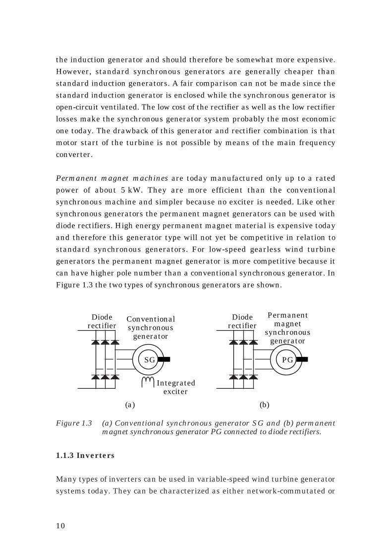
Permanent magnet machines are today manufactured only up to a ratedpower of about 5 kW. They are more efficient than the conventionalsynchronous machine and simpler because no exciter is needed. Like othersynchronous generators the permanent magnet generators can be used withdiode rectifiers. High energy permanent magnet material is expensive todayand therefore this generator type will not yet be competitive in relation tostandard synchronous generators. For low-speed gearless wind turbinegenerators the permanent magnet generator is more competitive because itcan have higher pole number than a conventional synchronous generator. InFigure 1.3 the two types of synchronous generators are shown.
SG PG
Dioderectifier
Integratedexciter
Conventionalsynchronous
generator
Permanentmagnet
synchronousgenerator
Dioderectifier
(a) (b)
Figure 1.3 (a) Conventional synchronous generator SG and (b) permanentmagnet synchronous generator PG connected to diode rectifiers.
1.1.3 Inverters
Many types of inverters can be used in variable-speed wind turbine generatorsystems today. They can be characterized as either network-commutated or
11
self-commutated. Self-commutated inverters are either current source orvoltage source inverters. Below the various types are presented. The ratedpower considered is in the range of 200 kW to 1 MW.
Self-commutated inverters: These are interesting because their networkdisturbance can be reduced to low levels. By using high switching frequencies,up to several kHz, the harmonics can be filtered easier than for a network-commutated thyristor inverter. Control of the reactive power flow is possiblefor this type of inverter making it easier to connect them to weak networks.Self-commutated inverters use pulse width modulation technique to reducethe harmonics. To make the harmonics low the switching frequency is often 3kHz or higher.
Self commutated inverters are usually made either with Gate Turn Offthyristors, GTOs, or transistors. The GTO inverters are not capable of higherswitching frequencies than about 1 kHz. That is not enough for reducing theharmonics substantially below those of a thyristor inverter with filter.Therefore, the GTO inverter is not considered as a choice for the future. It hasbeen made obsolete by the transistor inverters in the range up to 100-200kW. Today the most common transistor for this type of application is theinsulated gate bipolar transistor, IGBT. It is capable of handling large phasecurrents, about 400 A, and it is today used in converters with an rated acvoltage up to 400 V. IGBT converters for 690 V networks are supposed to beavailable soon. The drawback of the IGBT inverter today is that the largestinverters that can be made without parallelling the IGBTs are only about 200kW. A new technology, like the IGBT inverter, is expensive until large seriesare manufactured. These reasons make the IGBT inverters expensive to usefor large wind turbine generator systems. When the price of self-commutatedinverters decreases they are likely to be used for wind turbine generatorsystems because of their lower harmonics.
A self commutated inverter can be either a voltage source inverter or acurrent source inverter, see Figures 1.4 and 1.5. Today the voltage sourceinverter is the most usual type. If it is used to feed power to the network itmust have a constant voltage of the dc capacitor that is higher than the peakvoltage of the network. The generator is not capable of generating a constanthigh voltage at low speed and a dc-dc step-up converter must therefore beused to raise the voltage of the diode rectifier. In a system where the

12
generator is connected to a self-commutated rectifier this is not a problemsince that rectifier directly can produce a high voltage.
SG
400 V network
Voltage sourceinverter
570 V
Step-upconverter
0-570 V
Dioderectifier
0-420 V
Figure 1.4 A variable speed generator system. The frequency converterconsists of a diode rectifier, a step up converter and a voltagesource inverter. The transitors are shown as idealized switches.
SG
Dioderectifier
0-360 V400 V network 0-490 V
Current sourceinverter
Figure 1.5 A variable speed generator system. The inverter is a current sourceinverter with the transistors shown as idealized switches.
For a generator connected to a diode rectifier the self commutated currentsource inverter is interesting. It is, like the thyristor inverter, capable offeeding power to the network from very low voltages. Since the network is avoltage-stiff system it is from a control point of view good to use a currentsource inverter. The drawback of the current source inverter is a lowerefficiency than that of the voltage source inverter with step-up converter.

13
Network-commutated inverters: The usual type of network-commutatedinverter is the thyristor inverter. It is a very efficient, cheap and reliableinverter. It consumes reactive power and produces a lot of currentharmonics.
Cycloconverters with thyristors are common for large low-speed machines.They are only used with low frequencies, up to about 20 Hz and thereforethey do not fit the standard four-pole generators used in wind turbinegenerator systems. For rotor-cascade connected induction generators the lowfrequency range is no disadvantage. The harmonics from the cycloconverterare large and difficult to filter.
1.2 Wind turbine characteristics
A wind turbine as power source leads to special conditions. The shaft speed-power function is pre-determined because aerodynamic efficiency of theturbine depends on the ratio between the blade tip speed and the wind speed,called tip speed ratio. Maximum aerodynamic efficiency is obtained at a fixedtip speed ratio. To keep the turbine efficiency at its maximum, the speed ofthe turbine should be changed linearly with the wind speed.
The wind power is proportional to the cube of the wind speed. If a turbinecontrol program that is designed to optimize the energy production is used thewind speed turbine power function is also a cubic function. The turbine powercurve is shown in Figure 1.7 together with the turbine speed curve. In thisreport the turbine speed is assumed to be controllable above the rated windspeed by blade pitch control. The generator speed can then be considerednearly constant at wind speeds above the rated wind speed.
An ordinary wind turbine has a rated wind speed of about 13 to 14 m/s butthe median wind speed is much lower, about 5 to 7 m/s. Therefore, the powerof the turbine is most of the time considerably less than the rated power. Theprobability density of different wind speeds at the harbour in Falkenberg,Sweden, is shown in Figure 1.8.

14
Rated wind speedWind speed
Speed, Power
Turbine speed
Turbine power
Figure 1.7 The turbine power and turbine speed versus wind speed.
5 10 15 20
Wind speed (m/s)
0
0.02
0.04
0.06
0.08
0.1
0.12 Weighting function (s/m)
Figure 1.8 The weighting function of wind speeds at the harbour inFalkenberg, Sweden.
It can be seen that the wind speed usually is about half of the rated windspeed. Only during a small fraction of the time, less than 10 % of the year, theturbine produces rated power. Therefore, a generator system for a windturbine benefits more of low losses at low power than it does of low losses atrated power. At high power a variable-speed generator and converter havehigher losses than what a similar generator connected directly to the networkhas. However, at low power the variable-speed system can have lower lossesthan the network-connected generator. Therefore, the annual averageefficiency can be almost the same for both the systems.

15
1.3 Variable-speed wind turbines
Today most wind turbines run at constant generator speed and thus constantturbine speed. The reason for this is mainly that grid-connected ac generatorsdemand a fixed or almost fixed speed. Other reasons may be that resonanceproblems are more easily avoided if the speed is constant and that a passivestall control can be used to limit the power at wind speeds higher than therated wind speed.
Reasons for using variable speed instead of fixed speed is that the turbineefficiency can be increased, which raises the energy production a few percent.The noise emission at low wind speeds can be reduced. Variable-speedsystems also allow torque control of the generator and therefore themechanical stresses in the drive train can be reduced. Resonances in theturbine and drive train can also be damped and the power output can be keptsmoother. By lowering the mechanical stress the variable-speed systemallows a lighter design of the wind turbine. The economical benefits of this arevery difficult to estimate but they may be rather large.
1.4 A design example system
As an example a system for a 26 meter wind turbine generator system will bepresented in this report. The chosen turbine is a two-blade turbine with apassive pitch control. Its speed is limited by the pitch control which isactivated by aerodynamical forces. The turbine blade tips will be unpitcheduntil the turbine speed reaches a pre-set speed, at which the blade tips startto pitch. The speed will then be kept almost constant with variations of about± 5 %. This pitch system is completely passive and has no connection withthe power control in the electrical system. The power above rated wind speedcan be kept constant by the generator control. Below rated wind speed thegenerator torque will be controlled to keep the optimum tip speed ratio. Thepassive pitch system will be inactive and the blades unpitched. At theoptimum tip speed ratio, the turbine can produce 300 kW. The rated windspeed is then 13 m/s and the turbine speed 72 rpm. 72 rpm is a high speed forthis size of turbine. The speed can be reduced by designing the turbine bladesfor a lower optimum tip speed ratio.

16
Iant ng
IE
Idr
Ud
Idi Ii Inet
UnetUiUaIf
Pt Pg Pa Pi
UdiUdr+ ++
– ––
Pd
Figure 2.1 The total system and the quantities used.The generator can bemagnetized either by slip rings or by an integrated exciter.
2 The synchronous generator system
This chapter describes the generator and converter system as well as someaspects of its design. The component values for the 300 kW design examplesystem are calculated. Problems are discussed more from an engineers pointof view than from a theoretical point of view.
The complete generator system and its main components are shown inFigure 2.1. The turbine is described by its power Pt and speed nt. The speed israised to the generator speed ng via a gear. Pg is the input power to thegenerator shaft. The generator can be magnetized either directly by the fieldcurrent If fed from slip rings or by the exciter current IE. The exciter is anintegrated brushless exciter with rotating rectifier. The output electricalpower from the generator armature is denoted by Pa. The generatorarmature current Ia and voltage Ua are rectified by a three-phase dioderectifier.
The rectifier creates a dc voltage Udr and a dc current Idr. On the other sideof the dc filter the inverter controls the inverter dc voltage Udi and dc currentIdi. Ud is the mean dc voltage and Id is the mean dc current. The power of thedc link Pd is the mean value of the dc power, equal to Id Ud. The inverter accurrent is denoted Ii and the inverter ac voltage Ui. The ac power from theinverter is denoted Pi.

17
controllablerectifier
CUa lim
Efficiencycontrol*
Voltageregulator
Ua ref
*) Efficiency controlor reactive power control
Idi
IE ref
IE
Ua
Unet
Figure 2.2 The steady state voltage control of the generator.
The filter is used to take care of the current harmonics by short circuiting themajor part. The output of the generator system is the network current Inet.The network voltage is denoted Unet.
2.1 The control system
The control system of the generator and converter is used to control thegenerator torque by current control. In addition to this it can also, by voltagecontrol with Ua ref, either control the reactive power consumed by theinverter or optimize the generator-converter efficiency. The two controlfunctions are described below.
A voltage control diagram is shown in Figure 2.2. The control of the generatorvoltage is achieved by controlling the exciter current by IE ref. The controlmust be designed to keep the voltage of the generator below about 90 % ofthe inverter ac voltage Ua lim. Otherwise the inverter will not be able tocontrol the dc-current which will then increase uncontrollably. On the otherhand, the voltage of the generator should not be lower than necessary atrated power because that leads to a poor power factor of the inverter accurrent. Since the network voltage is not constant these two objectives canonly be reached if the generator voltage is controlled by the measured

18
Tg refTorquereference
curve ng
Ua
Torquecontrol
Idi ref
If
ng
Ia
ng
Ψ
Fieldcurrent
andflux link.
estim.
Figure 2.3 The steady state current control and torque control of thegenerator.
network voltage. The voltage control must also limit the generator flux. If thisis not done the generator will be saturated which will lead to unacceptablecore losses.
The second item to be controlled is the generator current. It is controlled bythe current reference value to the inverter Idi ref. At rated power and ratedspeed it is kept constant. Below rated power the current is controlled toobtain a generator shaft torque Tg ref according to the optimal speed-torquecurve of the turbine. The current demand is calculated from the torquedemand. In Figure 2.3 a diagram for a torque control system is shown.Because the field current in the rotor and the flux linkage Ψ of the stator can
not be directly measured they are estimated from the armature voltage,armature current and shaft speed.
A fast voltage control is important to keep a high power factor withoutcommutation problems during voltage dips on the network. If a fast torquecontrol is required due to, for instance, resonance problems in the drive train,the two control systems must be designed together. Otherwise they willdisturb each other. Because the current control is obtained by voltage controlof the inverter it is easily disturbed by the voltage control of the generator.The generator voltage depends on the generator current due to armature

19
reaction and thus the voltage control is easily disturbed by the currentcontrol. One simple solution is to design a fast controller for the generatorvoltage and a slower one for the generator current.
2.2 The generator
The generator is assumed to be a standard synchronous generator. Usually itis a four-pole, 1500 rpm, generator equipped with an integrated exciter and arotating rectifier. All the measurements in this report were made on a 50kVA synchronous generator. It is a Van Kaick generator that is modified byMyrén & Co AB. The generator, which has an integrated exciter, has alsobeen equipped with slip rings. This allows magnetization either by the exciteror by the slip rings. In Figure 2.4 the rating plate of the generator is shown.
2.2.1 Speed rating
In a variable speed system the speed of the generator is not restricted to thesynchronous speed at the network frequency, i.e. 1500 rpm for a 50 Hznetwork. Most small generators are designed to operate up to 1800 rpm,60 Hz, and the only upper limit is their survival speed, 2250 rpm forMecc Alte and Leroy Somer generators. Such high speed can, however, not beused as rated speed. The rated speed must be low enough to allow over-speedunder fault conditions, before the wind turbine emergency brakes areactivated.
FABR
TYP
EFFEKT
VOLT
~
NR
VARV
AMP
MYRÉN & CO AB - GÖTEBORGGEN
A VAN KAICK
DIB 42/50-4
50 - 60 kVA
360-416 V
MAGN 50 V 27 A
ELLER 40 V 1,1A
SYNKRON
50 - 60
424 118
1500 - 1800
83,5
Figure 2.4 The rating plate of the 50 kVA generator used in themeasurements.

20
-100
-50
0
50
100
0 5 10 15 20 25 30 35 40Time (ms)
Gen
erat
or c
urr
ent
(A)
Figure 2.5 Armature current wave shape in a generator connected to adiode rectifier.
The efficiency of a generator is usually increased slightly with increasingspeed. Using high speed also means that a smaller generator can be used toproduce the same power. A generator for 50 Hz operation is 20 % heavierthan a generator for 60 Hz and the same rated power.
A second limitation of the rated speed is the possible gear ratio. Speed ratiolarger than 1:25 between the generator speed and the turbine speed is notpossible for a normal two-stage gear. If higher ratios must be used a three-stage gear will be necessary. Each extra stage in the gear means 0.5 to 1 %extra losses. Since the efficiency of the generator only increases some tenthsof a percent there is no reason to use a three-stage gear to reach highgenerator speeds. For a two-stage planetary gear the limit of speed ratio ishigher, about 1:50.
2.2.2 Current rating
Harmonics in the armature current make it necessary to reduce thefundamental current from the rated current to avoid overheating of thearmature windings. The diode rectifier leads to generator currents that arenon-sinusoidal, instead they are more like square-shaped current pulses, seeFigure 2.5. In a standard generator only the fundamental component of thecurrents can produce useful torque on the generator shaft. The generatorwindings must be rated for the total r.m.s. value of the generator current
21
even if the active power is produced only by the fundamental component. Thearmature current of a generator loaded by a diode rectifier has an r.m.s. valuethat is about 5 to 7 % higher than the r.m.s. value of its fundamentalcomponent. This means that the generator must have a current rating atleast 5 % higher than what would be necessary if sinusoidal currents wereused.
2.2.3 Voltage rating
An other cause for derating when a diode rectifier is used is the voltage drop inthe commutation inductance. The diode commutation is a short-circuit of twoarmature phase windings during the time of the commutation. This short-circuit leads to a lower rectified voltage compared to the possible voltage ifthe commutation was instantaneous. The relative voltage drop due tocommutation can at rated load be approximately determined [6] by the perunit commutation reactance of the armature windings xr com as
∆UNUN 0
≈ 12 xr com (2.1)
where ∆UN is the commutation voltage drop at rated load and UN 0 is the
voltage at no load and rated flux.
Due to the commutations the voltage of the diode-loaded generator hascommutation notches. They can be seen in Figure 2.6 where the measuredline-to-line voltage of the generator is plotted. An undisturbed wave shape isalso shown for the first half-period. Each half-period has three commutationnotches.
The per unit commutation reactance can be approximately calculated fromthe subtransient reactances of the generator [7] as
xr com ≈ x"d axis + x"q axis
2 (2.2)

22
-600
-400
-200
0
200
400
600
0 5 10 15 20 25 30 35 40Time (ms)
Gen
erat
or v
olat
ge (
V)
Figure 2.6 Line-to-line armature voltage with commutation notches atalmost rated current. The no load voltage is shown for the firsthalf-period.
The per unit commutation reactance of standard synchronous generators,between 200 kVA and 1000 kVA and from two different manufacturers, havebeen investigated. The commutation reactance is in the range of 10 % to26 % with a mean value of about 15 %. The voltage drop of the commutationis then about 5 to 13 %. If the same generators are used with resistive loadthe reduction of armature voltage, when the generator is loaded, is lower. Thevoltage drop is then due to the leakage reactance and the armatureresistance. The resistive voltage drop is almost equal for both these cases. Itremains to compare the commutation voltage drop of a diode-loadedgenerator with the leakage reactance voltage drop of a resistively loadedgenerator. The leakage reactance voltage drop is only a few percent, andbeing 90 degree phase-shifted to the armature voltage it does not reduce thearmature voltage significantly. Hence, the equivalent armature voltage for adiode-loaded generator is about 5 to 13 % lower than for the same generatorresistively loaded.
2.2.4 Other aspects of the rating
With a diode rectifier the harmonics of the armature current induce currentin the damper windings under steady state operation. How large thesecurrents are and how much losses the damper winding thermally canwithstand has not been included in this study. However, simulations in [4]

23
indicate that they are about 0.2 % at rated current for the 50 kVA generator.They are not likely to overheat the damper windings and thus these lossesgive no reason to derate the generator.
Other additional losses of diode loaded synchronous generators must beincluded when the rating is decided. These losses can for example be eddycurrent losses in the end region due to the harmonic flux from the endwindings. They make overrating necessary only if they cause overheating ofsome part of the generator. The measurements made on the 50 kVAgenerator show only about 0.67 % additional losses due to the diode rectifier.These are such small losses that they probably can be neglected.
2.2.5 Generator rating
The harmonics of the armature current at diode load decrease thepermissible fundamental current about 5 to 7 % compared with a resistivelyloaded generator. Due to reactive voltage drop of the commutationinductance the possible rectified generator voltage is reduced about 5 to 13 %.Additional losses due to the diode load are small, and they are generally noreason for derating, if they do not occur in a critical hot spot of the generator.
The generator should have an apparent power rating, for sinusoidal currents,that is about 10 to 20 % larger than the active power that will be used withdiode load. If the generator is operated at a higher speed than the rated onethe permissible voltage will be raised proportionally to the speed. So, using a50 Hz machine at 60 Hz increases the voltage rating by 20 %. The limit forthe voltage is set by the isolation of the armature winding. Standard isolationfor 230/400V machines can be used for line-to-line voltages up to 700 V.
The conclusion is that a diode-loaded generator does not need to be biggerthan a generator, for the same active power, connected to a 50 Hz network.The fundamental component of the armature current has to be lower thanthe rated armature current. Also, the possible output voltage is decreased bythe commutations. However, the generator can instead be used with 20 %higher speed which compensates both for the current and voltage derating at50 Hz operation.
2.2.6 Generator efficiency

24
When the generator is connected to a diode rectifier the efficiency is lowerthan when it is connected to a resistive three-phase load. The reduction doesnot only depend on the increase in additional losses, but it is to a large extentdepending on reduced output power at rated current and rated flux. Except forthe additional losses the losses are the same at rated load for the resistiveload as well as for the diode load. The output power is, however, reduced due tothe voltage drop of the commutation and lower fundamental current when adiode rectifier is used.
At rated current the fundamental of the armature current is about 5 to 7 %lower with a diode load than with a resistive load. As mentioned earlier thevoltage at rated generator flux is about 5 to 13 % lower with a diode load.Totally the output power of the generator is 10 to 20 % lower with a diode loadthan with a resistive load. Constant losses and lower power reduce theefficiency. The maximum power of the generator loaded by a diode rectifier PN
diode can be expressed as a fraction Cdiode of the maximum power for thesame generator loaded by a three phase resistive load PN res
PN diode = Cdiode PN res (2.3)
Cdiode is about 80 to 90 % for the considered generators. The decrease inrated efficiency due to the derating at diode load, ∆ηN , is calculated. Ploss N is
the total generator losses at rated current and rated flux and PN is the ratedload. The rated efficiency of generators from 200 kVA to 1000 kVA is about94 to 96 % at cos(ϕ) = 1.0, here the efficiency with resistive load is assumed
to be 95 %. The reduction of efficiency when the generator is loaded by a dioderectifier instead of a resistive three phase load is
∆ηN = ηN res – ηN diode =
1 –
Ploss NPN diode
–
1 –
Ploss NPN res
=
=
5 %80 % –
5 %100 % = 1.25 % for Cdiode = 80 %
5 %90 % –
5 %100 % = 0.56 % for Cdiode = 90 %
(2.4)
The increase in additional losses for the 50 kVA generator when it isconnected to a diode rectifier is

25
∆PadPN
≈ 0.67 % (from measurements in Section 3.4.2) (2.5)
The relative increase in additional losses for generators from 200 to1000 kVA has not been found. Therefore, the value for the 50 kVA generatoris used instead. The relative increase is probably smaller for the largergenerators because their per unit losses are generally smaller than for the50 kVA generator.
The total efficiency reduction when a synchronous generator is loaded by adiode rectifier compared with resistive load is approximately 1.2 to 2.0 %.About half or more of the decrease in efficiency is because of decreasedoutput power and not because of increased losses. If the speed of thegenerator is higher for the diode-loaded generator compared to the resistivelyloaded generator, the difference in efficiency will be a little less.
2.2.7 Design example
The maximum continuous power of the generator system should be 300 kWat a rated dc voltage of Ud N = 600 V. This voltage is used because it is themaximum dc voltage of a standard thyristor inverter and using the maximumvoltage maximizes the efficiency. This means that the rated dc current is Idr
N = 500 A. The r.m.s. value of the generator current can be calculatedapproximately
Ia ≈ √ 23 Idr = 0.82 Idr (2.6)
Ia N ≈ 0.82 Idr N = 0.82 . 500 A = 410 A (2.7)
This formula is exact if the dc current is completely smooth. This is not thecase but the increase due to current ripple is only a few percent. Thus therated current of the generator should be a little more than 410 A.
According to Ekström [6] the dc voltage can be expressed as a function of thegenerator voltage and the dc current

26
Ud = 3 √ 2
π Ua – 3 ω Lr com
π Idr (2.8)
By solving Ua from this equation and using the rated values of the otherquantities, the rated generator voltage can be found as
Ua N = π
3 √ 2
Ud N + 3 ωN Lr com
π Idr N (2.9)
An LSA 47.5 generator from Leroy Somer is chosen. The per unitcommutation inductance is 12.6 % at 50 Hz and 410 A which corresponds to0.226 mH. The generator should, according to Equation (2.9), have a ratedvoltage of about 470 V if it is used at 50 Hz and 475 V at 60 Hz.
The voltage can be adjusted not only by choosing generators of differentvoltage rating. It can also be adjusted by changing the maximum speed of thegenerator. The maximum voltage of a generator is a linear function of speed
Ua max(nN) = n nN
Ua N (2.10)
For the design example turbine the optimum tip speed ratio λopt is 7.5 and
the diameter dt is 26 m. The rated wind speed vN is about 13 m/s. The tipspeed ratio is calculated using the following formula
λ = nt π dt
v (2.11)
The rated speed of the turbine should then be
nt N = vN λopt
π dt = 72 rpm (2.12)
The maximum corresponding generator speed with a gear ratio of 1:25 is
ng N = 25 nt N = 25 . 72 rpm = 1800 rpm (2.13)
The voltage rating of the generator at 1500 rpm should according to Equation(2.10) be

27
Lr com
Ua 0
√3Ldr
Ud
+
–Idr
ωa
Cd
Figure 2.7 The rectifier circuit including the rectifier reactor Ldr and thecommutation inductance Lr com.
Ua N = 1500 rpm1800 rpm 475 V = 395 V (2.14)
Summary: A generator with at least 410 A current rating and 395 V at1500 rpm should be used. In other words, a 284 kVA generator (50 Hz) allowsabout 300 kW maximum power at 1800 rpm. This is the smallest possiblegenerator. According to the data sheets of Leroy Somer generators an LSA47.5 M4 will be sufficient. It can continuously operate with a 290 kVA load at1500 rpm, 400 V and a class B temperature rise.
2.3 Rectifier
In the rectifier circuit the rectifier reactor Ldr is also included. The diagram ofthe generator and rectifier circuit can be seen in Figure 2.7. The dc voltage Ud
can be considered as a stiff voltage under steady state conditions if the dccapacitance Cd is large. Ua0 is the voltage induced by the airgap flux of thegenerator and Lr com is the commutation inductance of the generatorarmature.
2.3.1 Diode commutation
The commutation of the dc current between the armature phases of thesynchronous machine is slow because the armature windings have a largeinductance. At rated current the commutation can take up to about 1 ms.This leads to a lower mean voltage on the dc link at rated load compared withno load. In Figure 2.8 the potentials of the dc link are shown. A commutation

28
0.005 0.01 0.015 0.02Time [s]
-600
-400
-200
200
400
600
Potential [V]
t t1 2
Figure 2.8 The positive and negative potentials of the dc side of the rectifier.
on the positive side of the diode rectifier takes place between t1 and t2. The dcpotential is during this time equal to the mean value of two phase voltagesinstead of the highest phase potential.
2.3.2 Equivalent circuit
The commutation voltage drop can be modelled as a resistance in the dc linkRr com. The resistance value depends on the commutation inductance and thefrequency of the ac source. From Equation (2.8) the resistance value can beidentified
Rr com = 3 ω Lr com
π (2.15)
This resistance represents an inductive voltage drop on the ac side and is, ofcourse, not a source of losses.
The commutation inductance also helps smoothing the dc current. Betweentwo commutations the dc current passes a series connection of twocommutation inductances, see Figure 2.9. The effective inductance isbetween the commutation 2 Lr com.
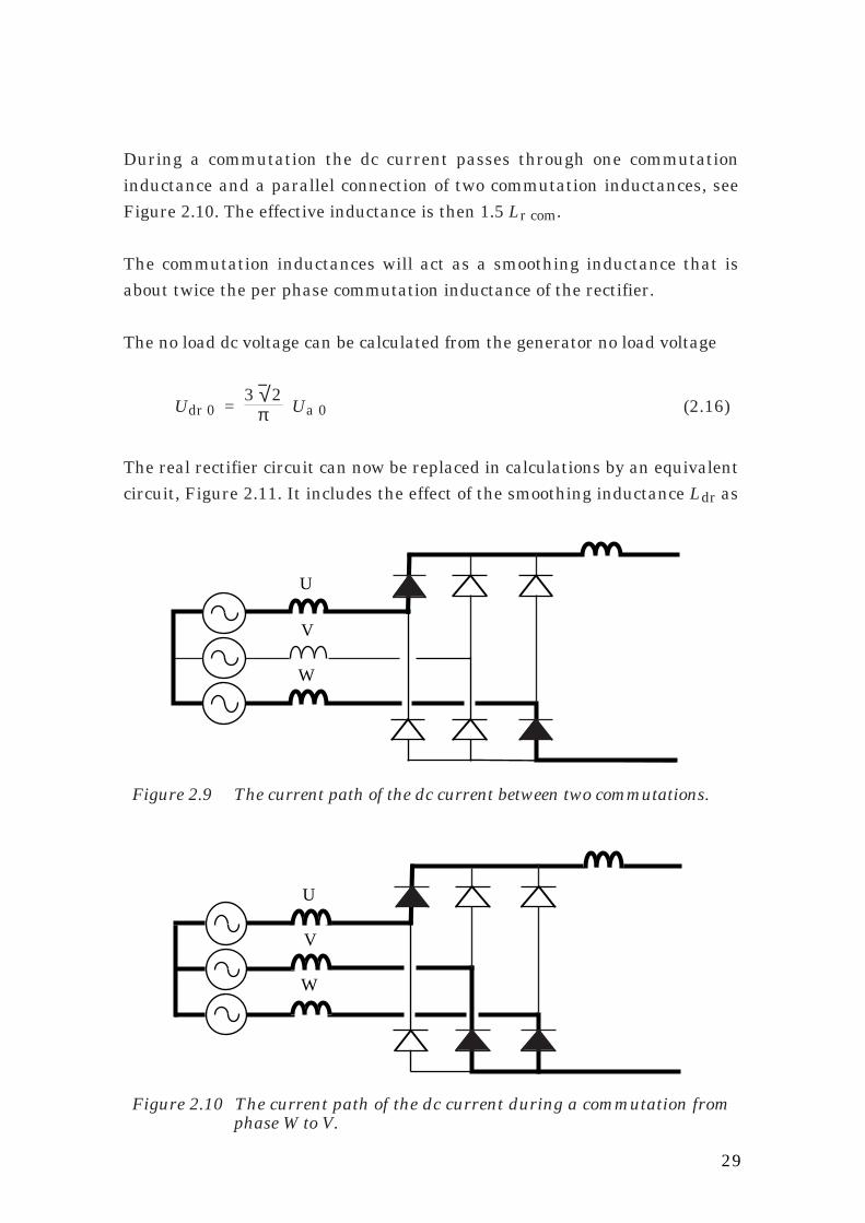
29
U
W
V
Figure 2.9 The current path of the dc current between two commutations.
During a commutation the dc current passes through one commutationinductance and a parallel connection of two commutation inductances, seeFigure 2.10. The effective inductance is then 1.5 Lr com.
The commutation inductances will act as a smoothing inductance that isabout twice the per phase commutation inductance of the rectifier.
The no load dc voltage can be calculated from the generator no load voltage
Udr 0 = 3 √ 2
π Ua 0 (2.16)
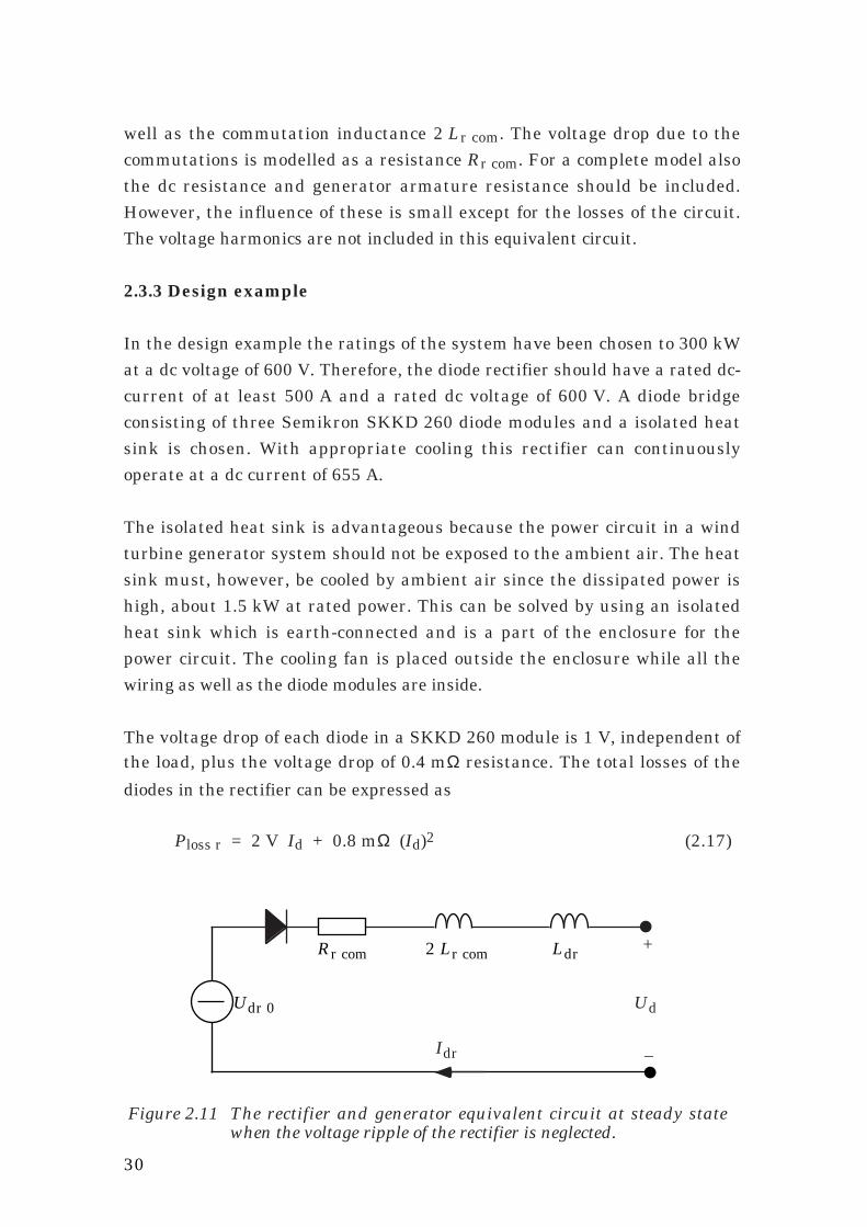
The real rectifier circuit can now be replaced in calculations by an equivalentcircuit, Figure 2.11. It includes the effect of the smoothing inductance Ldr as
U
W
V
Figure 2.10 The current path of the dc current during a commutation fromphase W to V.
30
Ud
+
–Idr
Ldr2 Lr comRr com
Udr 0
Figure 2.11 The rectifier and generator equivalent circuit at steady statewhen the voltage ripple of the rectifier is neglected.
well as the commutation inductance 2 Lr com. The voltage drop due to thecommutations is modelled as a resistance Rr com. For a complete model alsothe dc resistance and generator armature resistance should be included.However, the influence of these is small except for the losses of the circuit.The voltage harmonics are not included in this equivalent circuit.
2.3.3 Design example
In the design example the ratings of the system have been chosen to 300 kWat a dc voltage of 600 V. Therefore, the diode rectifier should have a rated dc-current of at least 500 A and a rated dc voltage of 600 V. A diode bridgeconsisting of three Semikron SKKD 260 diode modules and a isolated heatsink is chosen. With appropriate cooling this rectifier can continuouslyoperate at a dc current of 655 A.
The isolated heat sink is advantageous because the power circuit in a windturbine generator system should not be exposed to the ambient air. The heatsink must, however, be cooled by ambient air since the dissipated power ishigh, about 1.5 kW at rated power. This can be solved by using an isolatedheat sink which is earth-connected and is a part of the enclosure for thepower circuit. The cooling fan is placed outside the enclosure while all thewiring as well as the diode modules are inside.
The voltage drop of each diode in a SKKD 260 module is 1 V, independent ofthe load, plus the voltage drop of 0.4 mΩ resistance. The total losses of the
diodes in the rectifier can be expressed as
Ploss r = 2 V Id + 0.8 mΩ (Id)2 (2.17)

31
Expressed in per unit of the rectifier rated current and rated power the lossesare
ploss r = 0.33 % id + 0.07 % (id)2 (2.18)
Also some resistance in the connections and the cables should be included inthe losses leading to a higher resistive loss. The total rectifier losses can thenbe expressed as
ploss r = 0.33 % id + 0.17 % (id)2 (2.19)
2.4 Dc filter
In this section the dc harmonics will be described as well as some aspects ofthe design of the dc filter.
The dc-filter is used for four purposes:
(1) It is supposed to prevent harmonics from the rectifier to reach thenetwork. If there are harmonics from the rectifier in the network currentthey can not be easily filtered since their frequency changes with thegenerator speed. They can also cause resonance in the filter for the inverterharmonics because it has resonance frequencies below the frequencies of thecharacteristic harmonics.
(2) The dc filter should also keep the harmonics from the inverter low in therectifier dc current, since they would otherwise cause power oscillations andgenerator torque oscillations. For generator frequencies close to the networkfrequency these oscillations have low frequency and then they can causemechanical resonance.
(3) The harmonic content of the generator current depends to some extent onthe dc filter. The filter should be designed to keep the harmonic content lowbecause the harmonics cause extra losses in the generator.
(4) The dc filter design also affects the amount of harmonics produced by theinverter. The fourth purpose of the dc filter design is to assure that theinverter ac current harmonics are low and easy to filter.
32
Ld
Cd
LdiLdr
Cd
LdiLdr
Ld C
type A type Ctype B
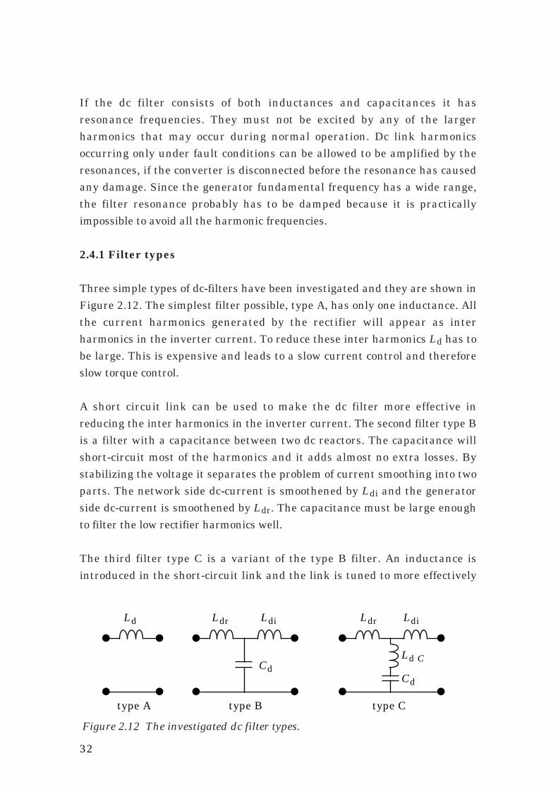
Figure 2.12 The investigated dc filter types.
If the dc filter consists of both inductances and capacitances it hasresonance frequencies. They must not be excited by any of the largerharmonics that may occur during normal operation. Dc link harmonicsoccurring only under fault conditions can be allowed to be amplified by theresonances, if the converter is disconnected before the resonance has causedany damage. Since the generator fundamental frequency has a wide range,the filter resonance probably has to be damped because it is practicallyimpossible to avoid all the harmonic frequencies.
2.4.1 Filter types
Three simple types of dc-filters have been investigated and they are shown inFigure 2.12. The simplest filter possible, type A, has only one inductance. Allthe current harmonics generated by the rectifier will appear as interharmonics in the inverter current. To reduce these inter harmonics Ld has tobe large. This is expensive and leads to a slow current control and thereforeslow torque control.
A short circuit link can be used to make the dc filter more effective inreducing the inter harmonics in the inverter current. The second filter type Bis a filter with a capacitance between two dc reactors. The capacitance willshort-circuit most of the harmonics and it adds almost no extra losses. Bystabilizing the voltage it separates the problem of current smoothing into twoparts. The network side dc-current is smoothened by Ldi and the generatorside dc-current is smoothened by Ldr. The capacitance must be large enoughto filter the low rectifier harmonics well.
The third filter type C is a variant of the type B filter. An inductance isintroduced in the short-circuit link and the link is tuned to more effectively

33
0 200 400 600 800 1000Freq. (Hz)
0.001
0.01
0.1
1
10.
Filter gain (A/V)
A typeB typeC type
I / Udi dr(A/V)
Figure 2.13 The inverter harmonic current relative to the rectifier harmonicvoltage, Idi / Udr.
short-circuit the largest fixed frequency harmonic. Only the harmonics fromthe inverter have constant frequencies. The largest harmonic from theinverter is the 300 Hz harmonic. But even without Ld C the 300 Hz current isdamped very well and the higher harmonics are reduced better without Ld C .
The harmonic current in the inverter dc current relative to the rectifierharmonic voltage, Idi / Udr, for the three types of dc filter is shown in Figure2.13. The choice of dc filter will probably be between type A and type B. Thefilter of type B has much better damping of the harmonics. The singleinductance Ld in filter A is higher than Ldi plus Ldr in filter B. On the otherhand, filter B is more complicated, has more parts and it probably has tohave a circuit to damp its resonance. Non-characteristic harmonics in theinverter current can cause resonance in the ac filter. These harmonics can bereduced much better by filter B than by filter A. Therefore, a filter of type Bis chosen for this design example, but this choice is not based on a completestudy of all the important aspects.
2.4.2 Harmonics in the dc link
The harmonics in the dc link are originating from the frequencies of thenetwork and the generator. The thyristor inverter and the diode rectifiergenerate a dc voltage with a superimposed ac voltage. Under ideal conditions
the harmonic frequencies of the dc voltages are integer multiples of six times

34
the ac frequencies. Only the sixth and twelfth harmonics cause ripplecurrents of considerable magnitude. From the inverter side a 300 Hz and a600 Hz current are generated. Depending on the generator frequency, from25 to 60 Hz, the diode rectifier generates a current harmonic with afrequency between 150 Hz and 360 Hz. The twelfth harmonic generated bythe diode rectifier has a frequency between 300 Hz and 720 Hz. Themagnitude of these voltage harmonics are depending on the generator voltageand on the firing angle of the inverter.
Under non-ideal conditions also other harmonics occur. If, for instance, thenetwork voltage or the generator voltage is unsymmetrical, a secondharmonic will also be generated. This should under normal conditions besmall, but must not be amplified by resonance in the dc filter. Non-ideal firingof the inverter thyristors also causes other harmonics. They can be of anymultiple of the fundamental frequency, but should for well-designed firingcontrol systems be small. In Figure 2.14 the harmonics from the inverter andrectifier are illustrated.
A reason for unusual harmonics in the dc link is fault conditions. Theseharmonics must of course not damage the converter and therefore theireffect must be calculated. If one ac phase is disconnected, because of forinstance a blown fuse, a very large second harmonic is generated. The three-phase rectifier will then start to act as a one phase rectifier.
If a diode or a thyristor valve is short-circuited due to a component failure, acurrent of the fundamental frequency is generated in the dc link. The resultshould be that a fuse is blown.
All the above mentioned voltage harmonics can cause high currents if theirfrequencies are close to the dc link resonance frequencies. Therefore, the dclink resonance frequencies have to be carefully chosen. It is clear that theresonance frequencies have to be below 150 Hz due to rectifier harmonics.The second harmonic of both the network frequency and the generatorfrequency must also be avoided, if the resonance is not well damped. Very lowresonance frequencies should also be avoided because they lead to a slow stepresponse of the current control. In the design example a filter with a rectifierside resonance at 75 Hz is suggested.

35
Har
mon
ics
from
the
rect
ifie
r 2:nd6:th
12:th
600300frequency
(Hz)100small
small
large
large2:nd
18:th
6:th12:th
Har
mon
ics
from
the
inve
rter
24:th
Figure 2.14 The harmonic frequencies in the dc filter under normalconditions and symmetrical firing.
2.4.3 Smoothing reactor of the diode rectifier
The current harmonics of the rectifier dc current depend on the magnitude ofthe harmonic voltages from the rectifier and on the smoothing inductance.For economical reasons the inductance should be minimized. The maximumacceptable ripple in the dc current must, therefore, be determined. On thegenerator side, the rectifier-induced harmonics are interesting mainlybecause they cause losses in the generator. Higher ripple means higher r.m.s.current and makes it necessary to use a higher current rating of thearmature winding.
The harmonics from the inverter are small if a filter of type B or C is used.They do not have to be considered when the size of Ldr is calculated.
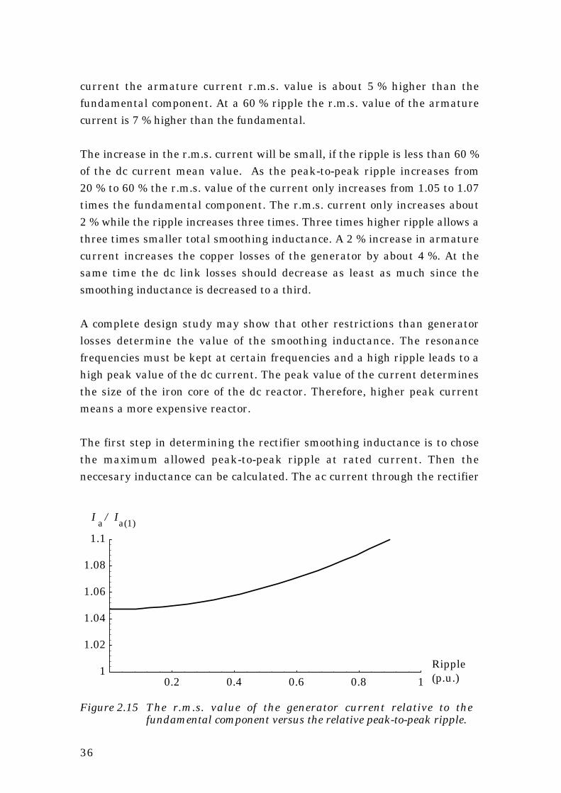
The r.m.s. value of the generator current can be calculated for different ripplemagnitudes. This is done assuming a ripple-free dc voltage Ud over the dcfilter capacitor and instantaneous commutations. The r.m.s. value as well asthe fundamental component of the generator current are calculated. InFigure 2.15 the relation between the r.m.s. value and the fundamental of thearmature current are plotted. For a perfectly smoothed dc current the r.m.s.value of the generator armature current is 4.7 % higher than its fundamentalcomponent. When the ripple increase the r.m.s. value of the generatorcurrent increases slowly. At a peak-to-peak ripple of 20 % of the rated dc
36
0.2 0.4 0.6 0.8 1
Ripple (p.u.)
1
1.02
1.04
1.06
1.08
1.1
I-a/I-a(1)I / Ia a(1)
Figure 2.15 The r.m.s. value of the generator current relative to thefundamental component versus the relative peak-to-peak ripple.
current the armature current r.m.s. value is about 5 % higher than thefundamental component. At a 60 % ripple the r.m.s. value of the armaturecurrent is 7 % higher than the fundamental.
The increase in the r.m.s. current will be small, if the ripple is less than 60 %of the dc current mean value. As the peak-to-peak ripple increases from20 % to 60 % the r.m.s. value of the current only increases from 1.05 to 1.07times the fundamental component. The r.m.s. current only increases about2 % while the ripple increases three times. Three times higher ripple allows athree times smaller total smoothing inductance. A 2 % increase in armaturecurrent increases the copper losses of the generator by about 4 %. At thesame time the dc link losses should decrease as least as much since thesmoothing inductance is decreased to a third.
A complete design study may show that other restrictions than generatorlosses determine the value of the smoothing inductance. The resonancefrequencies must be kept at certain frequencies and a high ripple leads to ahigh peak value of the dc current. The peak value of the current determinesthe size of the iron core of the dc reactor. Therefore, higher peak currentmeans a more expensive reactor.
The first step in determining the rectifier smoothing inductance is to chosethe maximum allowed peak-to-peak ripple at rated current. Then theneccesary inductance can be calculated. The ac current through the rectifier

37
t3 t4
I-dr
U-dr
U-d
I
U
U
dr
d
dr
3 4t t
Figure 2.16 The rectifier dc voltage Udr, dc capacitor voltage Ud and therectifier dc current Idr. The integration interval to find the peak-to-peak value is from t3 to t4.
dc reactor Ldr can under stationary conditions be found by integrating thevoltage over the total smoothing inductance. The voltage over the dc filtercapacitance is assumed to be a perfectly smooth dc voltage. The accomponent of the rectifier dc current is calculated as
Idr(t) = ⌡⌠
1Ltot
( ) Udr(t) – Ud dt (2.20)
To find the peak-to-peak ripple the integral (2.20) is evaluated from t3 to t4.The integration interval is the part of the voltage ripple period where thevoltage over the smoothing inductance is positive. The voltage on both sidesof the inductance as well as the dc current can be seen in Figure 2.16.
The relation between peak-to-peak ripple, generator voltage and totalsmoothing inductance can now be calculated for the rectifier as
∆Idr p-p = ⌡⌠
t3
t4
√ 2 UaLtot
sin(ω t +
π3 ) –
3π dt (2.21)
where
Ltot = Ldr + 2 Lr com t3: when the voltage over the inductance becomes positivet4: the voltage over the inductance becomes negative againUa is the no-load armature voltage

38
Both t3 and t4 are found as solutions for t in the equation
sin(ω t + π3 ) =
3π (2.22)
for which 0 < ω t3 < π6 and
π6 < ω t4 <
π3
2.4.4 Smoothing reactor of the inverter
The total r.m.s. value of the network ac current is also depending on the dcreactor Ldi just as for the rectifier. However, there are other aspects that aremore important for the inverter current than just minimizing the total r.m.s.value. The ac harmonics of the inverter current are very important toevaluate. They must be below certain limits to be accepted by the utility. Ifthe dc current is assumed perfectly smooth it can be shown that the currentharmonics are inversely proportional to their frequencies as described by theformula
I i (k) = I i (1)
k (2.23)
where k is the order of the harmonic.
If the ripple on the dc current increases most of the ac harmonics willdecrease. Only the fifth current harmonic increases with higher dc currentripple, see Figure 2.17. The magnitude of the harmonics is calculatedassuming a ripple-free dc voltage Ud, no overlap of the inverter ac currentsand a second order approximation of the ripple current wave shape.The increase of the fifth harmonic is, of course, important since it is thelargest current harmonic. However, being that large also makes it the onethat is almost always necessary to filter. If a good harmonic filter already isinstalled for the fifth harmonic, the effect of increasing it can be rather small.

39
0 0.2 0.4 0.6 0.8 1
Ripple (p.u.)
0.05
0.1
0.15
0.2
0.25
0.3
0.35
I-i(k)/I-i(1))
k=5
k=7
k=11k=13k=17
I / I i(k) i(1)
Figure 2.17 The ac current harmonics at rated power relative to thefundamental current at different dc current peak-to-peak ripple.No overlap and a second order approximation of the ripplecurrent wave shape is assumed.
The seventh, thirteenth and nineteenth current harmonics etc. are decreasedsignificantly by the ripple. The most interesting of these harmonics is theseventh one because it is often necessary to filter. If it can be reducedsignificantly, the seventh harmonic filter link may be unnecessary.
The eleventh, seventeenth and twentythird harmonics etc. are not reduced asmuch as the others. Therefore, they have to be filtered. This can be done bymeans of a filter link for the eleventh harmonic with a high passcharacteristic.
As can be seen in Figure 2.18 the seventh harmonic is low at high power butwill increase when the power is reduced below 0.6 p.u. It is, therefore, notsufficient only to make sure that the magnitude of the seventh harmonic islow at rated power; it is not allowed to increase too much at lower powereither. A seventh harmonic that is higher at low power than at rated powercan, however, be acceptable if most of the other harmonics then are lower.

40
0.2 0.4 0.6 0.8 1
P-d(p.u.)
0
0.05
0.1
0.15
0.2
I-i(k) (p.u.)
k=5
k=11k=7k=17k=13
i(k)(p.u.)
d(p.u.)
I
P
Figure 2.18 The magnitude of the current harmonics as a function of power.At rated power the dc current ripple is 35 % peak-to-peak. Theharmonics are calculated from a wave shape including the effectof changing fire angle but not including overlap.
There is, of course, a drawback of reducing ac harmonics by increasing the dccurrent ripple. The peak value of the inverter dc current then increases,demanding a higher current rating of the dc reactor.
No clear rules for choosing the inverter inductance can be given here. Aninteresting prospect, however, is to have a large current ripple of the dccurrent at rated current, approximately a peak-to-peak ripple in the order of35 % of the mean current. By doing so, it ought to be possible to design anappropriate ac filter with only two LC-links.
The first step in determining the inverter smoothing inductance is to chosethe maximum allowed peak-to-peak ripple at rated current. When it has beendecided the smoothing inductance can be calculated. Under stationaryconditions the ac current through the inverter dc reactor Ldi can be found byintegrating the voltage over the total smoothing inductance. The accomponent of the inverter current Idi can be calculated from the invertervoltage Udi and the dc voltage Ud as
Idi(t) = ⌡⌠
1Ltot
( ) Udi(t) – Ud dt (2.24)

41
t1 t2
I-di
U-diU-d
I
UU
t t
di
d
di
5 6
Figure 2.19 The inverter dc voltage Udi, dc capacitor voltage Ud and theinverter dc current Idi. The integration interval to find the peak-to-peak value is from t5 to t6.
To find the peak-to-peak value of the ripple, the integral is evaluated with alower limit t5 and an upper limit t6. The integration interval is equal to thepart of the voltage ripple period where the voltage over the smoothinginductance is positive. The voltage on booth sides of the inductance as well asthe dc current can be seen in Figure 2.19. The firing angle is 150˚.
Now the relation between peak-to-peak ripple, ac voltage, smoothinginductance and firing angle can be expressed as
∆Idi p-p = ⌡⌠
t5
t6
√ 2 UiLtot
sin(ω t +
π3 ) +
3π cos(α) dt (2.25)
where
Ltot = Ldi + 2 Li com Ui is the inverter ac voltaget5: the firing time of a thyristort6: the time the voltage over the inductance becomes negative
The time instants t5 and t6 are determined by the following equations
t5 = αω
(2.26)
sin(ω t6 + π3 ) = –
3π cos(αN) and α < ω t6 <
4 π3 (2.27)
42
For a thyristor inverter the firing angle α is about 150˚ to 155˚ at rated
voltage.
2.4.5 Dc capacitance
When Ldr and Ldi have been chosen the capacitance Cd can be calculated. Itis determined by the desired resonance frequency
Cd = 1
(Ldr + 2 Lr com) ( 2 π fr )2(2.28)
where fr is the chosen resonance frequency for the rectifier side harmonics.
If Cd is very large the values of the inductances already calculated can ofcourse be increased. An important reason to keep them small is, however,their resistive losses. The losses must be included in such a trade-off betweencapacitance and inductance.
2.4.6 Resonance damping
The resonance of the dc filter can be damped by means of an RLC circuittuned to the resonance frequency, see Figure 2.20. If only one damping circuitshould be used and both the rectifier side and the inverter side resonancefrequencies must be damped, the dc filter including the commutationinductances, must be symmetrical. In this way the two resonancefrequencies become equal because the total smoothing inductance on bothsides are equal
Ldi + 2 Li com = Ldr + 2 Lr com (2.29)

43
Cx
LdiLdr
LxRxCd
2 Li com2 Lr com
UdiUdr
Rectifier model Inverter modelDc filter with damping
Figure 2.20 The dc filter with damping circuit, rectifier and inverter model.
The the effect of the damping circuit on the transfer function of the dc filter isshown in Figure 2.21. For high harmonics (>100 Hz) the damping circuit canbe neglected and considered as an open circuit.
2.4.7 Dc filter calculations for the design example system
The design example generator and converter system has the following data:
Ac voltage of the inverter Ui N = 500 VNetwork angular frequency ω i = 2π 50 rad/s
Inverter commutation reactance xi com = 5 %Firing angle at rated load α N = 155˚
Rated dc current Id N = 500 ARated generator voltage Ua N = 475 VRated generator angular frequency ω g N = 2π 60 rad/s
Rect. commutation reactance xr com = 12.6 %Network per unit base impedance Zb net = 0.69 ΩGenerator per unit base impedance Zb g = 0.67 Ω
The damping circuit is not included in this design.
The peak-to-peak ripple of the inverter side dc current Idi at rated power ischosen to 35 % of the rated dc current. Then the value of Ldi can becalculated from Equations (2.25), (2.26) and (2.27)
t5 = α N
ω i = 8.61 ms (2.30)

44
0 100 200 300 400 500
Freqency (Hz)
0.01
0.1
1
10.
100.
1000.
Filter gain (A/V)
Without damping
With damping
I / U di dr(A/V)
Frequency (Hz)
Figure 2.21 The transfer function of the dc filter with and without damping.
sin(ω i t6 + π3 ) =
3π cos(α N) and α < ω i t6 <
4 π3 ⇒
⇒ t6 = 10.0 ms
(2.31)
Ldi + 2 Li com = √ 2 Ui N0.35 Id N
⌡⌠
t5
t6
sin(ω i t +
π3 ) +
3π cos(α N) dt =
= √ 2 Ui N0.35 Id N
–cos(ω i t +
π3 )
ω i + t
3π cos(α N)
t6 t5
= 0.75 mH (2.32)
The inverter commutation inductance is the transformer leakage inductanceplus a small contribution from the network reactance that can be neglected
Li com = xi com Zb net
ωi = 0.05
0.69 Ω 100 π rad/s = 0.1 mH (2.33)
This makes the dc filter inductance
Ldi = 0.55 mH (2.34)
45
The rated dc current is 500 A. The ripple current peak value is 0.5.35 %times the rated dc current. That makes the peak value of the dc current
Idi ≈
1 +
0.352 Idi
_ = 590 A (2.35)
The r.m.s. value of the rated current is approximately
Idi ≈ Idi_
= 500 A (2.36)
The inverter side smoothing reactor should have a core large enough for 590A peak current, but the inductor winding needs only be rated for about 500 Ar.m.s. value, and the inductance should be 0.55 mH.
The rectifier side smoothing inductance is calculated using Equations (2.21)and (2.22)
sin(ω g N tx + π3 ) =
3π ⇒ ω g N tx =
0.222 ± n 2 π
0.825 ± n 2 π rad (2.37)
0 < ω g N t3 < π6 ⇒ t3 = 0.59 ms
(2.38)
π6 < ωg N t4 <
π3 ⇒ t4 = 2.19 ms
(2.39)
Ldr + 2 Lr com = √ 2 Ua N∆Idr p-p
⌡⌠
t3
t4
sin(ω g N t +
π3 ) –
3π dt =
= √ 2 Ua N0.35 Id N
–cos(ω g N t +
π3 )
ω g N + t
3π
t4 t3
= 0.18 mH (2.40)
The commutation inductance of the generator is 12.6%
Lr com = xr com Zb gω g N
= 0.126 0.67 Ω
60 2 π rad/s = 0.224 mH (2.41)

46
which makes the rectifier dc inductance unnecessary.
Ldr = 0 mH (2.42)
Even without the rectifier inductance the ripple of the rectifier dc current willonly be about 70 A.
The dc capacitance is determined by the chosen resonance frequency. In thisexample the rectifier side resonance frequency is chosen to be 75 Hz. FromEquation (2.28) the dc capacitance can be calculated
Cd = 1
(Ldr + 2 Lr com) ( 2 π fr )2 = 10 000 µF (2.43)
The filter has now two resonance frequencies. The rectifier side resonancefrequency is 75 Hz and the inverter side resonance frequency is
f i = 1
2 π √(Ldi + 2 Li com) Cd = 58 Hz (2.44)
If both resonances must be damped with one damping circuit the rectifiershould be equipped with a reactor to make the resonance frequency equal onboth sides. In that case
Ldr = Ldi + 2 Li com – 2 Lr com = 0.3 mH (2.45)
The losses of the dc filter have not been calculated exactly, but they areestimated to be 0.7 % at rated load.
2.5 Inverter
Major reasons to choose the line-commutated thyristor inverter are the highefficiency, about 99 %, and the low price compared with other inverter types.Disadvantages are that it generates harmonic currents and consumesreactive power. The thyristor inverter is also difficult to protect at networkfaults.

47
Y:Y
Y:∆
≈5%
≈5%
<2%
~
Toconsumers
Filter
≈5%<2%
~
Filter
Transf.leakage
reactance
Transf.leakage
reactance
(a)
(b)
Figure 2.22 (a) Twelve-pulse and (b) six-pulse connected inverter. Equivalentsingle line scheme including the transformer leakage reactanceand network short-circuit reactance.
2.5.1 Inverter pulse number
Large thyristor inverters are often made of two six-pulse bridges in a twelve-pulse connection to reduce the current harmonics. The twelve-pulseconnection eliminates every second of the characteristic harmonicsgenerated from a six-pulse inverter. This is done by connecting the two six-pulse inverters in series on the dc side, see Figure 2.22. On the ac side theyare connected to two phase-shifted three-phase systems created by a three-winding transformer.
The drawbacks of the twelve-pulse connection for a medium size wind turbinegenerator system are both technical and economical.
The first technical drawback is that if the reactive power must becompensated, the network harmonic filters for the twelve-pulse connectionwill not be smaller than the ones used for a six-pulse bridge. The size of thefilter is determined by the reactive power consumed by the inverter and thetwelve-pulse inverter consumes as much reactive power as the six-pulseinverter.
In the twelve-pulse connection the filtering must be made on either both lowvoltage three-phase systems or on the high-voltage side of the transformer.Both these alternatives complicate the design and the manufacturing. A
48
filter connected to the 10 kV network can not easily be integrated with thewindmill electrical system. If the filter of the twelve-pulse inverter isconnected to the network side of the transformer it does not benefit of theleakage inductance of the transformer which makes a filter on the lowvoltage side several times more effective. In Figure 2.22 it can be seen thatthe harmonic voltages of the network, for the six-pulse connection, are only afraction of the harmonic voltages of the filter. The harmonic voltages arereduced because the voltage of the filter is divided by the network impedanceand the transformer impedance. In this example the harmonic voltages of thefilter are reduced at least to 2/7. For the twelve-pulse connection theharmonic voltages of the filter are instead the same as those of the network.The filter impedance must be lower in the twelve-pulse connection than in thesix pulse connection to reduce the network harmonic voltages to an equallylow level.
It is also easier to calculate the filtering effect and the resonance frequency ifthe filter is connected to the low voltage side of the transformer. Thetransformer reactance can for low harmonics be assumed to be substantiallylarger than the network impedance. Therefore, the usually unknownvariations in the network impedance do not change the effect of the filtermuch. A filter connected directly to the network must also be designed tofilter harmonics from other sources otherwise it might be overloaded. Thefilter connected on the low-voltage side of the transformer might also beburdened with harmonics from the network but to a much smaller extent.
The economical drawbacks of the twelve-pulse connection are a moreexpensive transformer and converter. The transformer is more expensive dueto the doubled secondary windings. For small converters, less than about 1MW, the six-pulse inverter is a standard equipment. It is cheaper to buy alarge six-pulse inverter than to use two smaller inverters in a twelve-pulseconnection.
A twelve-pulse connection is, for several reasons, not likely to be used insmall systems, at least not in systems less than 1 MW. The transformer andthe converter are more expensive. Even though every second of theharmonics are eliminated by the twelve-pulse inverter it is difficult to filterthe rest.
2.5.2 Protection circuits

49
Ldi
Cd
Networktransformer
Lto CtoThto
VDR
– +
Figure 2.23 Thyristor inverter, turn-off circuit (shaded) and networktransformer.
Short-circuit of the ac network can cause problems for the inverter, becausethe fuses will blow, if there is no turn-off circuit. The turn-off circuit must becapable of breaking the dc current of the inverter and the energy stored in theinverter inductance must be dissipated. A direct short-circuit at the inverterac supply is one cause for this problem, but that is an unusual event. Moreimportant is that each time the high-voltage network is disconnected the dccurrent from the inverter will saturate the transformer core and thetransformer will start to act as a short-circuit. This type of network fault is adifficult problem for the thyristor inverter. When the network voltagedisappears the converter can not control the dc-current, hence the currentincreases uncontrollably until the fuses blow. The inverter does not sufferany damage of the short-circuit but it is expensive to have to change fuses inall wind turbine generator systems as soon as the network has had a failure.The inverter must therefore have ways to disconnect at over-current. Thiscan be achieved by a turn-off circuit connected to the three thyristors on oneside of the inverter.
An example of a turn-off circuit is shown in Figure 2.23. The capacitor of theturn-off circuit should always be charged to a positive voltage that is used toturn off the conducting thyristor in the upper part of the six-pulse inverter.The dc current is instead forced to pass through the varistor of the turn-offcircuit. Energy stored in Ldi is dissipated in the varistor and the currentdecreases to zero within a few milliseconds. A turn-off circuit can be triggeredby over-current. At the same time as the turn-off circuit is triggered the

50
inverter thyristor firing will be blocked.
Thyristor converters for high power, several MW, are often made withoutfuses and with fast ac breakers instead. This technique might be useful alsofor smaller converters instead of a turn-off circuit. The difference betweenconverters with fuses and converters with fast breakers is that thethyristors must withstand higher fault currents and for a longer time if theyare only protected by fast breakers. An other drawback is that fast breakersare very expensive.
2.5.3 Design example
As the design example inverter an ABB Tyrak Midi II is chosen. It is a two-quadrant six pulse thyristor module with a rated current of 530 A and a ratedac voltage of 500 V. The rated dc voltage is then 600 V. The total losses atrated current are 2200 W, at 50 % of rated current 1200 W and at no load350 W. The losses of the inverter can be separated into a constant powerloss, a current-independent voltage drop and a resistive voltage drop.Expressed in per unit of the 300 kW system the inverter losses are
ploss i(id) = 0.12 % + 0.52 % id + 0.10 % id2 (2.46)
The total losses are 0.74 % at the rated current. The losses with cables,fuses, main switch and other auxiliary parts are of course higher. Since theselosses are equal for both variable-speed and constant-speed systems theyare not included in the loss model.
51
3 Model of generator and converter losses
In this chapter theoretical models of the losses of a synchronous generator, adiode-thyristor converter and a gear are derived. The model of the generatorlosses is verified for a 50 kVA generator. This loss model can be used tocalculate the generator shaft torque from measurements of the armaturepower and the shaft speed. It also allows efficiency optimization bycontrolling the generator flux. Finally, the model parameters are derived forthe 300 kW design example system.
The friction and windage losses as well as the core losses are calculated andexpressed as their equivalent braking torque on the generator shaft. That isconvenient in the torque control point of view. It is also a natural way tocalculate friction and windage losses and core losses because they have thecharacter of a speed-dependent braking torque. The copper losses in thearmature and field windings are not speed-dependent and they are thereforeexpressed as power losses.
The loss model is a per unit model, but note that it is not the usual per unitsystem that is used. Since the generator and converter have many separatecircuits, different base values can be used, and are used, for the currents inthe different circuits. The principle of the used per unit system is that allpowers in all circuits should be comparable to each other while all currents,voltages, speed and torque should have the value of 1 p.u. at rated load of thegenerator converter system. To be able to see easily what effect each losscomponent has on the system efficiency, all powers and losses are related tothe rated input power of the system. The per unit quantities are generallydenoted by lower case letters and the normal quantities by upper caseletters. The exception is the speed n which in per unit is denoted n'.
3.1 Model of machine losses
The losses in the machine can be divided into several independent parts, seeFigure 3.1.
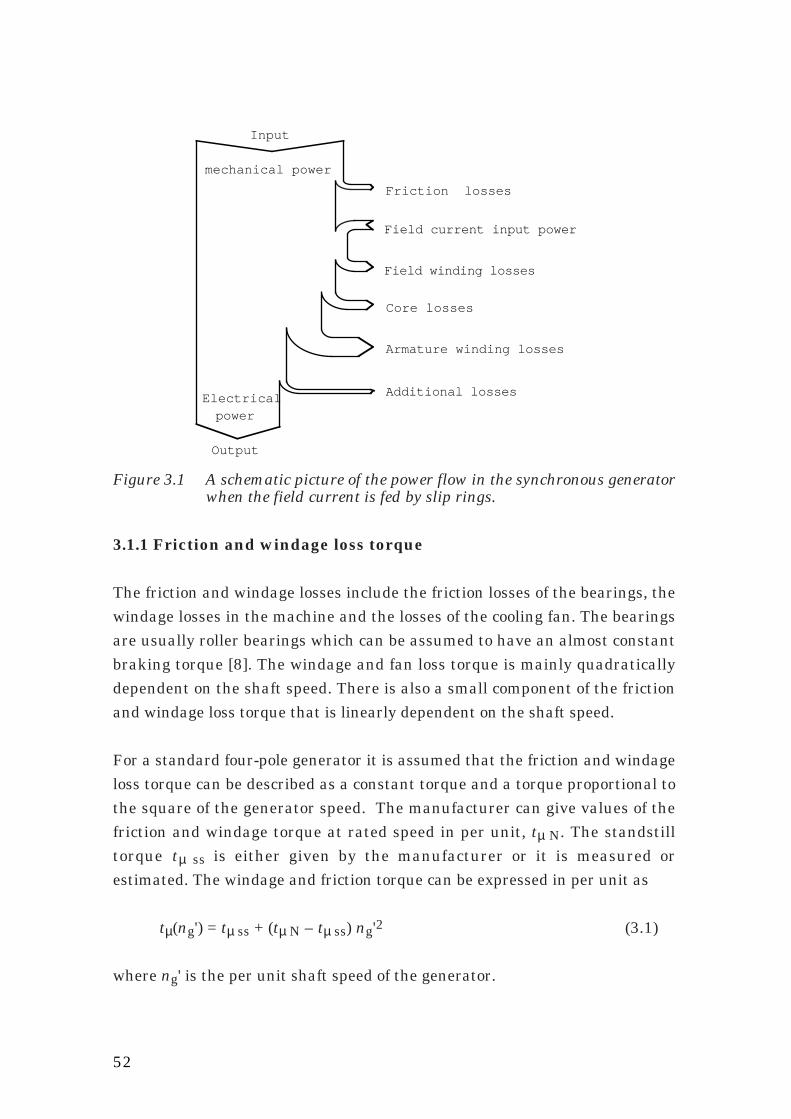
52
Additional losses
Friction losses
Core losses
Armature winding losses
Input
mechanical power
Field current input power
Electricalpower
Output
Field winding losses
Figure 3.1 A schematic picture of the power flow in the synchronous generatorwhen the field current is fed by slip rings.
3.1.1 Friction and windage loss torque
The friction and windage losses include the friction losses of the bearings, thewindage losses in the machine and the losses of the cooling fan. The bearingsare usually roller bearings which can be assumed to have an almost constantbraking torque [8]. The windage and fan loss torque is mainly quadraticallydependent on the shaft speed. There is also a small component of the frictionand windage loss torque that is linearly dependent on the shaft speed.
For a standard four-pole generator it is assumed that the friction and windageloss torque can be described as a constant torque and a torque proportional tothe square of the generator speed. The manufacturer can give values of thefriction and windage torque at rated speed in per unit, tµ N. The standstilltorque tµ ss is either given by the manufacturer or it is measured orestimated. The windage and friction torque can be expressed in per unit as
tµ(ng') = tµ ss + (tµ N – tµ ss) ng'2 (3.1)
where ng' is the per unit shaft speed of the generator.
53
3.1.2 Core losses
The core losses PFe can be separated into two parts, hysteresis losses PHy
and eddy current losses PFt. Both are functions of the magnitude of thealternating flux B and the frequency f.
PFe = PHy(B,f)) + PFt(B,f) (3.2)
Eddy current losses in an iron core can be expressed as
PFt(B,f) ~ B2 f y (3.3)
where 1.9 ≤ y ≤ 2, according to [9]. In the same way the hysteresis losses canbe expressed as
PHy(B,f) ~ Bx f (3.4)
where 1.5 ≤ x ≤ 2.3, according to [9].
For electrical machines these functions are generally used with y = 2 andx = 2. These values are within the limits found in [9]. To use them simplifiesthe calculation of the total core losses because both the eddy current lossesand the hysteresis losses then change in the same way with changing flux.That allows a separation of the total core losses into a product of the fluxdependent hysteresis losses and a frequency-dependent eddy current factor (1 + f C ) that includes the effect of the eddy current losses
PFe(B,f) = PHy(B,f) ( 1 + f C ) (3.5)
where C is a constant and PHy(B,f) is
PHy(B,f) ~ B2 f (3.6)
The value of B in the above equations is usually the peak value of thealternating flux density. In an electric machine the flux linkage can be used inthe loss formulas, instead of the peak value of the flux, if the flux wave-shapedoes not change too much when the load change.

54
The generator flux wave shape is not constant due to armature reaction andsaturation. But the only practical way to estimate the peak value of the fluxis by using the flux linkage of the stator winding. That method is used for thisloss model. Instead of the flux density and frequency, B and f, the flux linkageand the generator speed, Ψ and ng, can be used
PFe(Ψ,ng) ~ Ψ2 ng ( 1 + ng C ) (3.7)
Since the hysteresis loss function includes a flux-dependent factor times theshaft speed the power losses can be calculated as an equivalent brakingtorque
TFe = PFeωg
~ PFeng
(3.8)
⇒ TFe(Ψ,ng) = CHy Ψ2 ( 1 + ng CFt ) (3.9)
where CHy and CFt are machine dependent core loss constants.
The use of the speed as a variable instead of the frequency is chosen becausethe speed is already used as a variable for the friction and windage losses andit is usual to measure the generator speed in a wind turbine generatorsystem. For a synchronous generator in steady state operation the speed andfrequency are equal when they are expressed in per unit.
The presented theory does not take the effects of saturation into account.The saturation makes the core losses increase more than the theory predictswhen the flux increases. To approximate the core loss torque with a resonableaccurracy is, however, possible even with this simple model. Only the coreloss torque at rated flux and speed as well as the eddy current factor at ratedspeed have to be known. By using values of the core loss torque at rated fluxwhich includes the effect of saturation the absolute error of the core losses iskept low even though the theoretical flux dependency of the core loss torque isnot exact. The hysteresis loss function will only have a quadratic termaccording to the theoretical equation. The per unit model of the core losstorque is
tFe(ng',ψ) = tFe N
1 + CFt ψ 2 (1 + CFt ng') (3.10)
55
where tfeN is the total core loss torque at rated load and rated speed and CFt
is the ratio of the eddy current losses PFt N and the hysteresis losses PHy N atrated flux and speed
CFt = PFt NPHy N
(3.11)
3.1.3 Winding losses
For sinusoidal currents the copper losses of the armature windings can beexpressed as
PCu a = 3 Ra I 2a (3.12)
where Ia is the r.m.s. armature current and Ra is the equivalent per phasearmature reistance. Expressed in per unit the armature copper losses are
pCu a = ra i 2a (3.13)
For nonsinusoidal currents the calculation of the losses can be much morecomplicated. The fundamental current component and the current harmonicsdo not meet the same effective resistance. The skin effect gives rise to ahigher resistance for the harmonics. However, when using a diode rectifier thelow-order harmonics dominate and the resistance for the fifth and seventhharmonics can for a normal stator winding be assumed to be about the sameas the resistance for the fundamental component. Therefore, the model usesthe measured total r.m.s. value of the armature current to calculate thearmature winding losses.
The field winding losses can be calculated in the same way as the armaturewinding losses
PCu f = Rf I2f (3.14)
where Rf is the field winding resistance and If is the field current. Expressed inper unit the field winding losses are
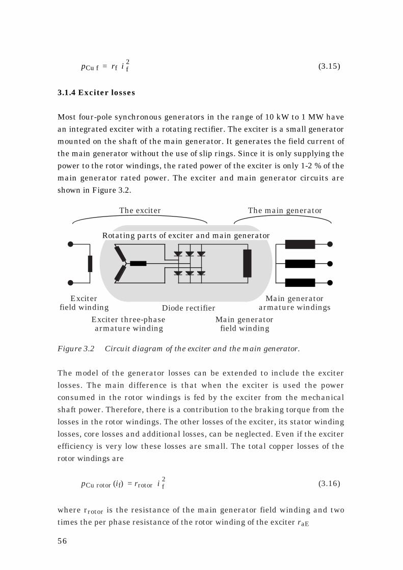
56
pCu f = rf i2f (3.15)
3.1.4 Exciter losses
Most four-pole synchronous generators in the range of 10 kW to 1 MW havean integrated exciter with a rotating rectifier. The exciter is a small generatormounted on the shaft of the main generator. It generates the field current ofthe main generator without the use of slip rings. Since it is only supplying thepower to the rotor windings, the rated power of the exciter is only 1-2 % of themain generator rated power. The exciter and main generator circuits areshown in Figure 3.2.
Main generatorfield winding
Main generatorarmature windingsDiode rectifier
Exciterfield winding
Exciter three-phasearmature winding
The exciter The main generator
Rotating parts of exciter and main generator
Figure 3.2 Circuit diagram of the exciter and the main generator.
The model of the generator losses can be extended to include the exciterlosses. The main difference is that when the exciter is used the powerconsumed in the rotor windings is fed by the exciter from the mechanicalshaft power. Therefore, there is a contribution to the braking torque from thelosses in the rotor windings. The other losses of the exciter, its stator windinglosses, core losses and additional losses, can be neglected. Even if the exciterefficiency is very low these losses are small. The total copper losses of therotor windings are
pCu rotor (if) = rrotor i2f (3.16)
where rrotor is the resistance of the main generator field winding and twotimes the per phase resistance of the rotor winding of the exciter raE
57
rrotor = rf + 2 raE (3.17)
One problem in finding the rotor losses in a generator with exciter is that themain field current is not possible to measure. In some way the field currentmust be modelled as a function of the exciter current or, as used later, byestimating the field current from the flux linkage and the armature current.
3.1.5 Additional losses
One part of the additional losses is the losses in the damper windings. Atsteady state operation and sinusoidal armature currents the damper windingcurrents are almost zero. They should not cause losses when the generator isloaded resistively. However, when the generator is loaded by a diode rectifierthere are steady state losses in the damper windings. Because of theharmonics in the armature mmf wave, currents flow in the damper windings.The currents in the damper windings are approximately proportional to thearmature current. Other parts of the additional losses are for instance thecore losses associated with the distortion of the flux wave and the stray fluxin the end regions that cause extra core losses.
According to [10] the additional losses can be approximated as beingproportional to the square of the armature current. They can, therefore,easiest be included in the loss modell by adding a fictitious resistance to thearmature resistance in the loss calculations. If the additional losses at ratedload, Pad N, are known, the fictitious armature resistance of the additionallosses can be calculated as
Rad = Pad N
3 I2a N
(3.18)
The additional losses are, expressed in per unit
pad N = rad i 2a (3.19)

58
3.1.6 Complete generator loss model
The total per unit generator losses can be modelled as the sum of fivedifferent types of losses, using only four variables. For a generator with sliprings the losses are
p loss g(ng',ψ,ia,if) =
=ng' ( )t µ(ng') + t Fe(ng',ψ) + pCu a (ia) + pCu f (if) + pad (ia) (3.20)
If slip rings are used, the field winding losses are not fed from mechanicalpower from the generator shaft and therefore they do not contribute to thebraking torque
t loss g(ng',ψ,ia) = t µ(ng') + t Fe(ng',ψ) + pCu a (ia) + pad (ia)
ng' (3.21)
where the different losses are defined as
t µ(ng') = t µ ss + (t µ N – t µ ss) ng'2 (3.1)
t Fe(ng',ψ) = t Fe N
1 + CFt ψ2 (1 + CFt ng') (3.10)
pCu a (ia) = ra ia2 (3.13)
pCu f (if) = rf if 2 (3.15)
pad (ia) = rad ia2 (3.19)
The loss torque formula, Equation (3.21), can be used to calculate the shafttorque if the armature power pa is known
t g(pa,ng',ψ,ia) = pang' + t loss g(ng',ψ,ia) (3.22)
If the total generator losses should be minimized also the field losses must beincluded. Then the power loss formula, Equation (3.20), is used to minimizethe total losses by changing the generator flux.
59
For generators having an integrated exciter the power loss formula ischanged. The total rotor losses increase because both the field winding lossesand the exciter winding losses are included
p loss g(ng',ψ,ia,if) =
ng' ( )t µ(ng') + t Fe(ng',ψ) + pCu a (ia) + pad (ia) + pCu rotor(if) (3.23)
In this case the rotor losses also contribute to the braking torque:
t loss g(ng',ψ,ia,if) =
t µ(ng') + t Fe(ng',ψ) + pCu a (ia) + pad (ia) + pCu rotor (if)
ng' (3.24)
where the rotor losses are defined as
pCu rotor (if) = rrotor if 2 (3.16)
3.1.7 Calculating the generator flux
In order to use the model of the generator core losses, the airgap flux linkageof the generator must be known. At no load the generator armature voltagedivided by the speed of the generator is used to calculate the flux linkage.When the generator is loaded, the same method can be used. The difference isthat the flux linkage is then calculated using the induced voltage of thearmature divided by the generator speed. The induced voltage Ea must becalculated from the armature voltage Ua. For sinusoidal currents the inducedvoltage can be found simply by adding the voltage drop in the armaturewinding. For resistive load the induced voltage is
Ea = √ (Ua + Ra Ia)2 + (ω La σ Ia)2 (3.25)
where La σ is the armature leakage inductance.
If a diode rectifier is used the generator currents are nonsinusoidal and theequation will be different. Due to the commutation inductance the voltagedrop is larger than for sinusoidal currents and it can be found if the model inFigure 2.11 is used. There the induced armature voltage can be calculated by

60
adding the voltage drop over Rr com to the measured dc voltage and dividingby (3 √ 2)/π. The induced voltage is calculated, neglecting the armatureresistance
Ea = π
3 √ 2 (Ud + Rr com Id) (3.26)
From this induced voltage of the armature winding the generator flux linkagecan be calculated
Ψ = Eaωg
= Eap ng
(3.27)
where p is the pole pair number of the generator
3.1.8 Estimating the field current
For a generator magnetized by an integral exciter the field current can not bemeasured. Therefore, it has to be estimated. From a simple linear theory,neglecting saturation effects, the total magnetization current of thegenerator can be calculated. For a linear generator the magnetization currentis proportional to the flux linkage. The magnetization current phasor is thefield current phasor plus the armature current phasor. A resonableapproximation for a generator loaded by a diode rectifier is that thefundamental of the armature current is in phase with the induced armaturevoltage. That is equal to assuming that the rectifier commutations areinstantaneous.
In Figure 3.3 the current distributions of the machine can be seen. Ea is theinduced airgap voltage phasor and Im is the total magnetization currentphasor. From the figure it can be seen that
Im 2 + Ia 2 = If 2 (3.28)
where Im = Km Ψ = Km Ψ
Ia = Ka Ia If = Kf If

61
Km, Ka and Kf are machine dependent factors. They are used to reduce all thecurrents to equivalent airgap current densities. By using these expressionsfor the current phasor magnitudes in Equation (3.28) the field current can becalculated
(Kf If)2 = (Km Ψ )2 + (Ka Ia)2 (3.29)
The same equation can be used for the per unit quantities
(kf if)2 = (km ψ )2 + (ka ia)2 (3.30)
where kf = 1 + xs2
km = 1 ka = xs
for the used per unit system
Saturation can also be included in this model if the flux linkage as a functionof the magnetizing current is known. That function is then used instead of thelinear relationship assumed here.
If
Ea
Ia Im
Ψ
Figure 3.3 The generator currents, flux linkage and induced voltage phasors.
3.1.9 Parameters for the generator loss model
The parameters needed for the simplified model are found in Table 3.1. On theordinary data sheet the stator resistance, field winding resistance,synchronous reactance and subtransient reactances can be found. Also thecore losses at rated flux and speed, the friction losses at rated speed as well
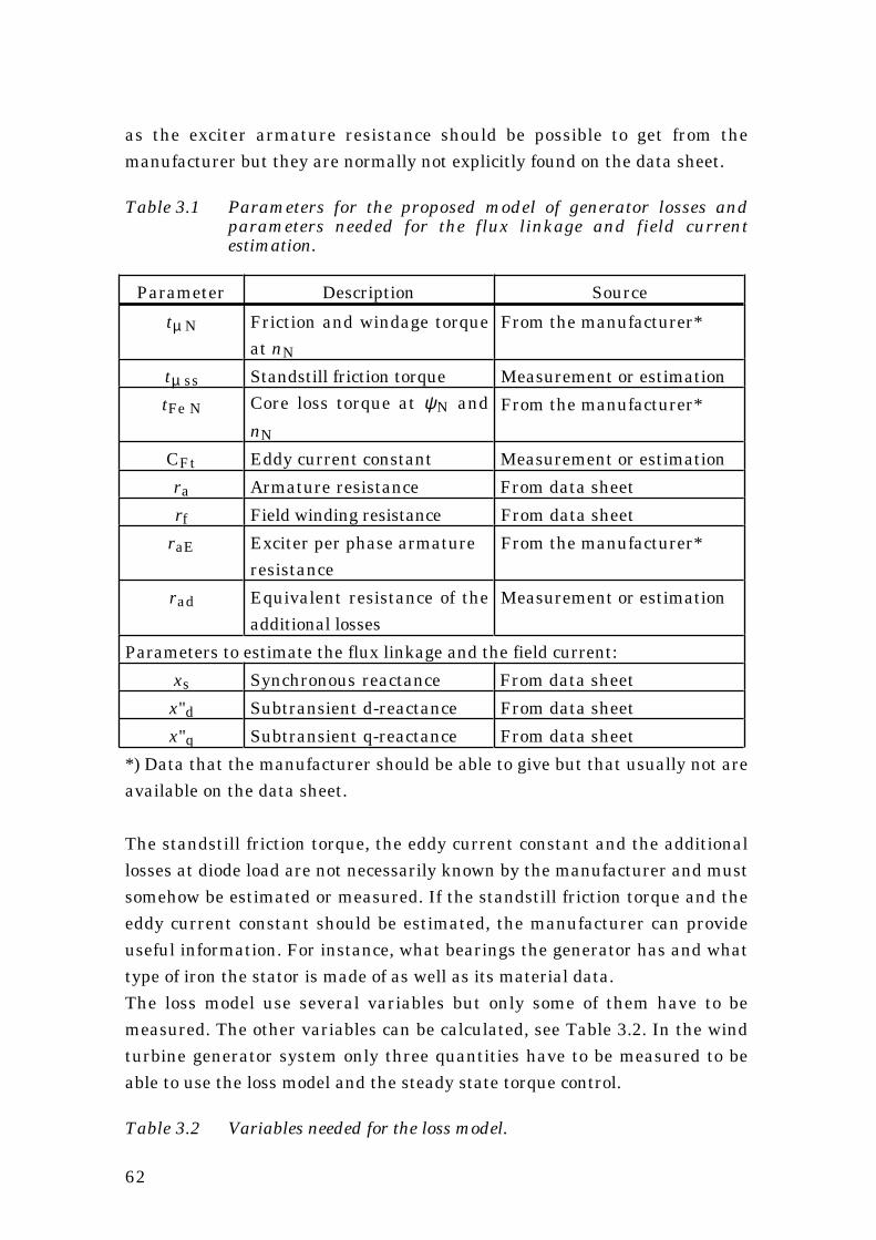
62
as the exciter armature resistance should be possible to get from themanufacturer but they are normally not explicitly found on the data sheet.
Table 3.1 Parameters for the proposed model of generator losses andparameters needed for the flux linkage and field currentestimation.
Parameter Description Source
tµ N Friction and windage torqueat nN
From the manufacturer*
tµ ss Standstill friction torque Measurement or estimation
tFe N Core loss torque at ψN and
nN
From the manufacturer*
CFt Eddy current constant Measurement or estimation
ra Armature resistance From data sheet
rf Field winding resistance From data sheet
raE Exciter per phase armatureresistance
From the manufacturer*
rad Equivalent resistance of theadditional losses
Measurement or estimation
Parameters to estimate the flux linkage and the field current:
xs Synchronous reactance From data sheet
x"d Subtransient d-reactance From data sheet
x"q Subtransient q-reactance From data sheet
*) Data that the manufacturer should be able to give but that usually not areavailable on the data sheet.
The standstill friction torque, the eddy current constant and the additionallosses at diode load are not necessarily known by the manufacturer and mustsomehow be estimated or measured. If the standstill friction torque and theeddy current constant should be estimated, the manufacturer can provideuseful information. For instance, what bearings the generator has and whattype of iron the stator is made of as well as its material data.The loss model use several variables but only some of them have to bemeasured. The other variables can be calculated, see Table 3.2. In the windturbine generator system only three quantities have to be measured to beable to use the loss model and the steady state torque control.
Table 3.2 Variables needed for the loss model.

63
Variable
Id measured
Ud measured
ng measured
Pa = Id Ud – diode losses
Ia = 0.78 Id
Ψ = π (Ud + Rr com Id)
3 √ 2 p ng
(*
If = 1Kf
√ (Km Ψ )2 + (Ka Ia)2
*) p is the pole pair number of the generator
3.1.10 Errors of the generator model
The errors of the loss model are of three different types. First there is an errordue to the simplifications and assumptions made. This error is often difficultto estimate since the simplifications usually are made because the realfunctions are not known. Secondly there is always an error in thedetermination of the model parameters. These errors can usually beestimated from instrument accuracy and measurement method. Finally, theparameters may change with the load and the environmental conditions. Forexample, winding resistances depend on the temperature.
3.1.11 Error in the windage and friction losses
The model of friction and windage torque is not exact due to the errors of theused parameters and the errors of the approximate speed dependency. Themodel has two parameters: the friction and windage torque at rated speedtµ N and the standstill torque tµ ss. Both these parameters are determined bymeasurement or estimation. The error of the parameters can be estimatedand their maximum and minimum value can be found. The variations in thespeed dependency of the torque is much more difficult to find. It has only beenestimated based on measurements on three different electrical machines. Toestimate the total error of the friction and windage torque the worst casemaximum and minimum friction and windage torque functions are estimated.It is here assumed that the maximum worst case torque has a linear termthat at rated speed is as large as the quadratic term. Maximum torques atrated speed and standstill are used as parameters. The maximum torque isestimated

64
tµ max(ng') = tµ ss max + (tµ N max – tµ ss max) ng' + ng'2
2 (3.31)
The worst case minimum torque is assumed to have no first-order term.Minimum torques at rated speed and standstill are used as parameters
tµ min(ng') = tµ ss min + (tµ N min – tµ ss min) ng'2 (3.32)
If the model torque function and the estimated maximum and minimumtorque functions are plotted in the same diagram, an estimation of the modelerror can be made, see Figure 3.4. In this case the error in the rated frictiontorque, tµ N, is assumed to be ±20 %. The error in the standstill friction torque,tµ ss, is assumed to be ±50 %. The total error of the friction and windage modelis found to be about 0.25 times the friction torque at rated speed
∆Tµ = 0.25 Tµ N = 0.25 ( tµ N TN) (3.33)
Generator speed (p.u.)
0,00
0,25
0,50
0 0,25 0,5 0,75 1
µ max
µ model
µ min
t
t
t
Fri
ctio
n an
d w
inda
ge t
orqu
e
in p
erce
nt o
f rat
ed t
orqu
e
Figure 3.4 The model friction and windage torque and the estimatedmaximum and minimum limits for the torque.
Error in the core losses
The core loss torque model has two parameters: the core loss torque at ratedload tFe N and the eddy current constant CFt. The model of the core losstorque is

65
tFe(ng',ψ) = tFe N ψ2 1 + CFt ng'
1 + CFt (3.10)
It is a product of the hysteresis loss torque and the eddy current factor.These two parts have different types of error. The parameters maximum andminimum value have to be estimated: tFe N min, tFe N max, CFt min andCFt max. First the error of the hysteresis loss torque is estimated. Usingx = 1.5 in Equation (3.4) and tFe N max the maximum hysteresis loss torque is
tHy max(ψ) ~ ψ1.5 tFe N max (3.34)
If x = 2.3 and tFe N min is used the minimum hysteresis loss torque will be
tHy min(ψ) ~ ψ2.3 tFe N min (3.35)
The hysteresis loss torque at rated flux is assumed to have an error of ±10 %.From Figure 3.5 the error of the hysteresis loss torque can then be estimatedto be about 20 % of the hysteresis loss torque at rated flux. The worst caseerror of the hysteresis loss approximation is at about 0.5 p.u. flux linkage.
Generator flux (p.u.)
Hys
tere
sis
torq
ue
(%)
0,0
0,5
1,0
1,5
2,0
2,5
0 0,25 0,5 0,75 1
Hy max
Hy model
Hy min
t
t
t
Figure 3.5 Model of hysteresis losses and an estimation of its error.In Figure 3.6 the error of the eddy current factor is shown. The maximumeddy current factor CFe max is derived from Equations (3.3) and (3.5). InEquation (3.3) y = 1.9 and CFt min is used
CFe max = 1 + CFt min (ng')0.9
1 + CFt min(3.36)
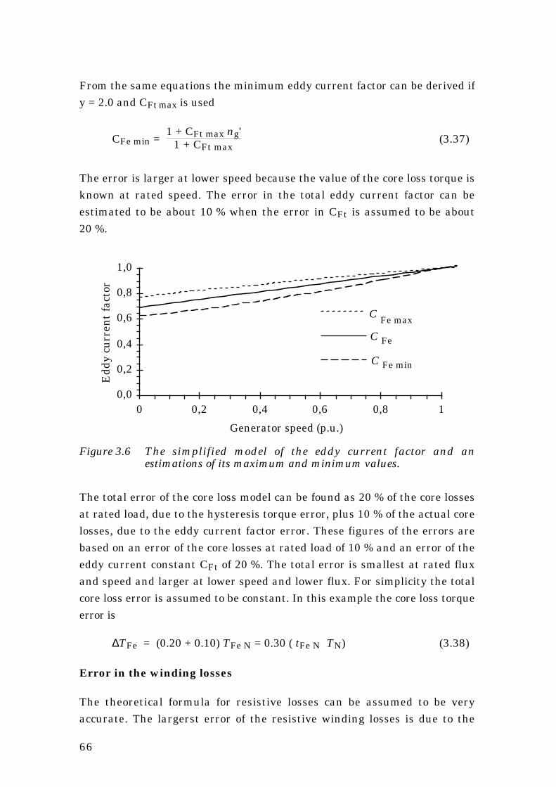
66
From the same equations the minimum eddy current factor can be derived ify = 2.0 and CFt max is used
CFe min = 1 + CFt max ng'
1 + CFt max(3.37)
The error is larger at lower speed because the value of the core loss torque isknown at rated speed. The error in the total eddy current factor can beestimated to be about 10 % when the error in CFt is assumed to be about20 %.
Generator speed (p.u.)
Edd
y cu
rren
t fa
ctor
0,0
0,2
0,4
0,6
0,8
1,0
0 0,2 0,4 0,6 0,8 1
Fe max
Fe min
Fe
C
C
C
Figure 3.6 The simplified model of the eddy current factor and anestimations of its maximum and minimum values.
The total error of the core loss model can be found as 20 % of the core lossesat rated load, due to the hysteresis torque error, plus 10 % of the actual corelosses, due to the eddy current factor error. These figures of the errors arebased on an error of the core losses at rated load of 10 % and an error of theeddy current constant CFt of 20 %. The total error is smallest at rated fluxand speed and larger at lower speed and lower flux. For simplicity the totalcore loss error is assumed to be constant. In this example the core loss torqueerror is
∆TFe = (0.20 + 0.10) TFe N = 0.30 ( tFe N TN) (3.38)
Error in the winding losses
The theoretical formula for resistive losses can be assumed to be veryaccurate. The largerst error of the resistive winding losses is due to the
67
temperature dependence of the winding resistance. In a normal wind turbinegenerator the winding temperature can in the extreme case vary betweenabout –20˚ and +120˚ C. This gives a variation of the winding resistance of±25 % if a resistance value for 50˚ C is used. In a generator rated for atemperature rise according to class B, max 80˚ C, it is however not usualwith winding temperature outside the range of +10˚ to +90˚ C. The change ofresistance is then ±15 % if a resistance value for 50˚ C is used.
The error of the winding losses is estimated to be about ±20 % of the actuallosses. About 15 % is due to normal temperature changes and about 5 % dueto an error in the measured winding resistance. The temperature of thewindings may under extreme weather conditions pass these limits giving alarger error of the winding losses. In Sweden that will probably only occur forsome percent of the time. The errors of the resistive winding losses can beexpressed as
∆PCu a = 0.20 PCu a = 0.20 ( 3 Ra I 2a) = 0.20 ( ra i 2
a PN) (3.39)
∆PCu f = 0.20 PCu f = 0.20 ( Rf I2f ) = 0.20 ( rf i
2f PN) (3.40)
If the error of the model must be reduced, the resistance value can bechanged according to a measurement of the winding temperature.
Error in the additional losses
Since the mechanisms of the additional losses are not investigated, the errorof their approximation can not be derived. If they are measured at rated loadthe error can be estimated to be less than 50 %
∆Pad = 0.50 Pad = 0.50 ( 3 Rad I 2a) = 0.50 ( rad i 2
a PN)
(3.41)
Total model error
The error of the power loss is smaller at partial load than at rated load andthe total error can be estimated as an error dependent on the speed, plus onepart that changes with armature current and one that changes with the fieldcurrent

68
∆PlossPN
=
ng ∆Tµ
ng N TN +
ng ∆TFeng N TN
+
∆PCu a
PN +
∆PadPN
+ ∆PCu f
PN =
= ( 0.25 tµ N + 0.30 tFe N ) ng' + ( 0.20 ra + 0.50 rad ) ia2 + 0.20 rf if 2
(3.42)
The error of the calculated power loss decreases to zero if the speed,armature current and field current all are decreasing to zero. The error canalso be expressed as a loss torque error
∆TlossTN
= ∆TµTN
+ ∆TFeTN
+ ∆PCu a / ngPN / ng N
+ ∆Pad / ngPN / ng N
+ ∆PCu f / ngPN / ng N
=
= (0.25 tµ N + 0.30 tFe N) + (0.20 ra + 0.50 rad) ia2 + 0.20 rf if 2
ng' (3.43)
From Equation (3.43) it can be seen that the torque error does not decreaseto zero even if the currents decrease to zero.
The higher the generator efficiency the lower the error is in the calculatedshaft torque, because the error is in percent of the losses and not in percentof the power of the generator. The error described in this chapter is the modelerror. The total error can be larger because of errors in the measurements ofthe generator armature power, armature voltage, armature current, fieldcurrent and shaft speed. If an exciter is used there will also be an error in theestimation of the field current.
3.2 Model of the converter losses
The converter losses have to be modelled to be able to compare the averageefficiency of a variable speed generator and converter system with theaverage efficiency of a constant speed generator. The converter losses aredivided into rectifier losses Ploss r, dc filter losses Ploss d and inverter lossesPloss i. Losses due to the dc current ripple are neglected.
The losses of the diode bridge are due to the voltage drop in the semiconductormaterial and to the switching losses. The voltage drop has two parts:
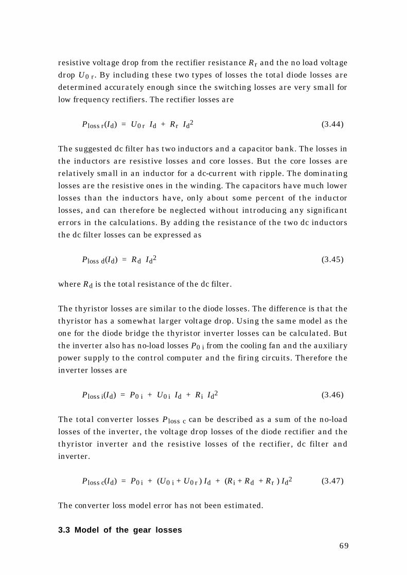
69
resistive voltage drop from the rectifier resistance Rr and the no load voltagedrop U0 r. By including these two types of losses the total diode losses aredetermined accurately enough since the switching losses are very small forlow frequency rectifiers. The rectifier losses are
Ploss r(Id) = U0 r Id + Rr Id2 (3.44)
The suggested dc filter has two inductors and a capacitor bank. The losses inthe inductors are resistive losses and core losses. But the core losses arerelatively small in an inductor for a dc-current with ripple. The dominatinglosses are the resistive ones in the winding. The capacitors have much lowerlosses than the inductors have, only about some percent of the inductorlosses, and can therefore be neglected without introducing any significanterrors in the calculations. By adding the resistance of the two dc inductorsthe dc filter losses can be expressed as
Ploss d(Id) = Rd Id2 (3.45)
where Rd is the total resistance of the dc filter.
The thyristor losses are similar to the diode losses. The difference is that thethyristor has a somewhat larger voltage drop. Using the same model as theone for the diode bridge the thyristor inverter losses can be calculated. Butthe inverter also has no-load losses P0 i from the cooling fan and the auxiliarypower supply to the control computer and the firing circuits. Therefore theinverter losses are
Ploss i(Id) = P0 i + U0 i Id + Ri Id2 (3.46)
The total converter losses Ploss c can be described as a sum of the no-loadlosses of the inverter, the voltage drop losses of the diode rectifier and thethyristor inverter and the resistive losses of the rectifier, dc filter andinverter.
Ploss c(Id) = P0 i + (U0 i + U0 r ) Id + (Ri + Rd + Rr ) Id2 (3.47)
The converter loss model error has not been estimated.
3.3 Model of the gear losses

70
The gear losses have not been measured. A theoretical model of the losses ofa normal gear is presented in [11]. The losses of the gear are divided into twoparts. The gear mesh losses which are a fixed percentage of the input powerindependent of the gear shaft speed. The gear mesh losses are determined bythe design of the teeth of the cog-wheels. Friction losses are the other part ofthe losses and they are mainly due to bearing friction, windage and oilchurning losses. The bearings, normally being roller bearings, give rise to analmost constant breaking torque. Windage power losses are generallyproportional to the speed in cube. Expressed as a braking torque they areproportional to the speed in square. The oil churning losses are difficult todetermine but the breaking torque should increase at least proportionally tothe rotational speed of the gear. If it is not known how the bearing, oilchurning and windage losses depend on the speed, a simplified function can beused. It is certain that those losses increase at least linearly with the speed.The following approximation of gear losses over-estimates the losses for allspeeds up to the rated speed
ploss gear(pt,n't) = t0 gear n't + ( 1 – ηmesh ) pt (3.48)
where t0 gear is the per unit friction torque at rated speed and ηmesh the gear
mesh efficiency.
3.4 Verification of the generator loss model
The losses are measured at various loads and under different conditions toverify the loss model. A first step is to verify the generator loss model forsinusoidal currents at resistive load. Then the model is used to predict thelosses for a diode loaded generator. The error when the loss model is used tocalculate the shaft torque from the armature power is also presented.
The losses are measured only indirectly by measuring the input mechanicalpower and the output armature power of the generator. Therefore, the modelerror is calculated as the shaft torque predicted by the model minus themeasured generator shaft torque.
When comparing the model and the measurements the error consists of twoparts. Besides the error of the model also the error due to the inaccuracy ofthe measured variables will show in this comparison. The error in the torque
71
measurement is totally about 1.5 Nm. The predicted torque of the model isalso suffering from the error in the output power. The output power of thegenerator is measured with a wattmeter that has an error of 0.5 % of theactual power range. That range changes during the measurement but themaximum error is always larger than 0.5 % of the actual power. The errors ofthe measured variables for the loss model, like armature current andgenerator speed, do not much affect the error of the predicted torque. Thetotal effect of the inaccuracy of the measurements is equal to about 3.0 Nmat rated load and about 1.5 Nm at no load.
3.4.1 The laboratory system
Measurements were made on a system with the 50 kVA generator earlierdescribed. For that purpose a system with generator and frequency converteror resistive three-phase load has been built in the laboratory. The laboratorysystem and the measurement equipment used are shown in Figure 3.7. Allthe measurements are made at steady state operation.
The generator is driven by a dc machine fed from a thyristor rectifier withspeed control. No gear is included in the laboratory system. On the shaftbetween the dc motor and the synchronous generator the shaft torque andspeed are measured. The generator is magnetized mainly by sliprings but forcomparison it has also been magnetized by its integrated exciter. When it ismagnetized by the sliprings both the field current and the field voltage aremeasured. The field current is fed from a current-controlled three-phasethyristor rectifier via a fourth order LC-filter. The ripple on the field current isonly about one percent.
The exciter current is fed by a current regulating dc power supply. To be ableto find the relation between the exciter current and the field current the fieldvoltage is measured also when the exciter is used. From the field voltage andthe field resistance the field current can then be calculated.
The armature power is measured by a three-phase digital power meterincluding harmonics up to 1 kHz. To estimate the generator flux at resistiveload the armature r.m.s. voltage is measured and to calculate the statorwinding copper losses the r.m.s. value of the armature current is alsomeasured.

72
The generator power is either fed to a three-phase resistive load or to afrequency converter. The frequency converter consists of a three-phase dioderectifier, a dc filter and a thyristor inverter. In the dc filter the dc power aswell as the dc current and voltage are measured.
Ia
ng
IE
UaIf
AP
V
A
V
A
Pa
Tg
Uf
T n
DC
Three-phaseresistive load
IdrUd
PUI
Pd
Figure 3.7 The laboratory set-up with measurement instrumentation.
3.4.2 Parameter determination of the laboratory system
The per unit quantities are presented in Table 3.3 together with thecorresponding base values for the laboratory system. Note that the ratedvalues of the system are used as base values, and the rated values of thegenerator can differ from these. There are also two current base values: onefor the field current and one for the armature current. All of the base valuesin Table 3.3 can not be chosen independently. The power, speed and armaturecurrent base values can be chosen. Then the torque, field current, flux linkageand resistance base values can be calculated.
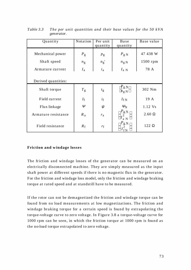
73
Table 3.3 The per unit quantities and their base values for the 50 kVAgenerator.
Quantity Notation Per unitquantity
Basequantity
Base value
Mechanical power Pg pg Pg N 47 438 W
Shaft speed ng ng' ng N 1500 rpm
Armature current Ia ia Ia N 78 A
Derived quantities:
Shaft torque Tg tg
Pg N
ng N 302 Nm
Field current If if If N 19 A
Flux linkage Ψ ψ ΨN 1.12 Vs
Armature resistance Ra ra
Pg N
I2a N
2.60 Ω
Field resistance Rf rf
Pg N
I2f N
122 Ω
Friction and windage losses
The friction and windage losses of the generator can be measured on anelectrically disconnected machine. They are simply measured as the inputshaft power at different speeds if there is no magnetic flux in the generator.For the friction and windage loss model, only the friction and windage brakingtorque at rated speed and at standstill have to be measured.
If the rotor can not be demagnetized the friction and windage torque can befound from no load measurements at low magnetizations. The friction andwindage braking torque for a certain speed is found by extrapolating thetorque-voltage curve to zero voltage. In Figure 3.8 a torque-voltage curve for1000 rpm can be seen, in which the friction torque at 1000 rpm is found asthe no-load torque extrapolated to zero voltage.

74
Armature voltage (V)
No-
load
tor
que
(Nm
)
0
2
4
6
8
10
0 50 100 150 200 250 300
Tµ(1000 rpm)
If = 0 A
If = 15 AIf = 12.5 A
If = 10 A
If = 7.5 A
If = 5 AIf = 2.5 A
Figure 3.8 A no-load torque-voltage curve used to find the friction loss torqueat 1000 rpm for the 50 kVA generator.
In Figure 3.9 the zero voltage torque from a number of such curves has beenplotted in the same diagram to form the torque-speed curve for the frictionand windage losses.
The standstill friction torque can be found by extrapolating the friction andwindage loss torque for low speeds down to zero speed. For the 50 kVAgenerator the friction and windage parameters are
Tµ ss = 0.468 Nm and Tµ N = 1.694 Nm(3.49)
tµ ss = 0.155 % and tµ N = 0.407 % (3.50)
Generator speed (rpm)
Fri
ctio
n to
rque
(Nm
)
0
0,5
1
1,5
2
2,5
0 500 1000 1500
T
T
µ N
µ ss

75
Figure 3.9 The torque-speed points from measurements of the friction andwindage losses of the 50 kVA generator, and the model functiondrawn as a line.
Core losses
Measurements made at different speeds are necessary for separating thehysteresis losses and the eddy current losses. From no-load measurementsthe core losses can be calculated as the input mechanical power minus thefriction losses. First the eddy current constant is determined and then thehysteresis loss torque is determined.
To separate the hysteresis losses from the eddy current losses the measuredtotal core loss torque is plotted as a function of the generator speed for somefixed values of the field current. At no load a fixed field current is equal to afixed flux linkage. The measured core loss torque for the 50 kVA generator isshown in Figure 3.10. The hysteresis torque can be determined if the curve isextrapolated to zero speed. The speed dependency of the data should formstraight lines, according to Equation (3.10). Figure 3.10 shows that the speeddependency for high flux is not linear, especially not for low speeds of thegenerator. But if the model is to be used in a wind turbine generator system,speeds below 500 rpm will be of no interest. The curve fit should be made onlyfor the data between the lowest and the highest speeds used in thatparticular wind turbine generator system.
Based on the measured data, it is possible to get one value of the eddycurrent constant for each value of the flux linkage (field current). The eddycurrent constant can for each flux linkage be calculated by the followingequation
CFt(Ψ) = TFe(Ψ,1500 rpm) – TFe(Ψ,0 rpm)
TFe(Ψ,0 rpm) (3.51)
The value of the eddy current constant used in the model is the mean value ofthe constants for the different flux linkages. The results can be found in Table3.4. The mean value of the eddy current constant is calculated
CFt = 0.44 (3.52)
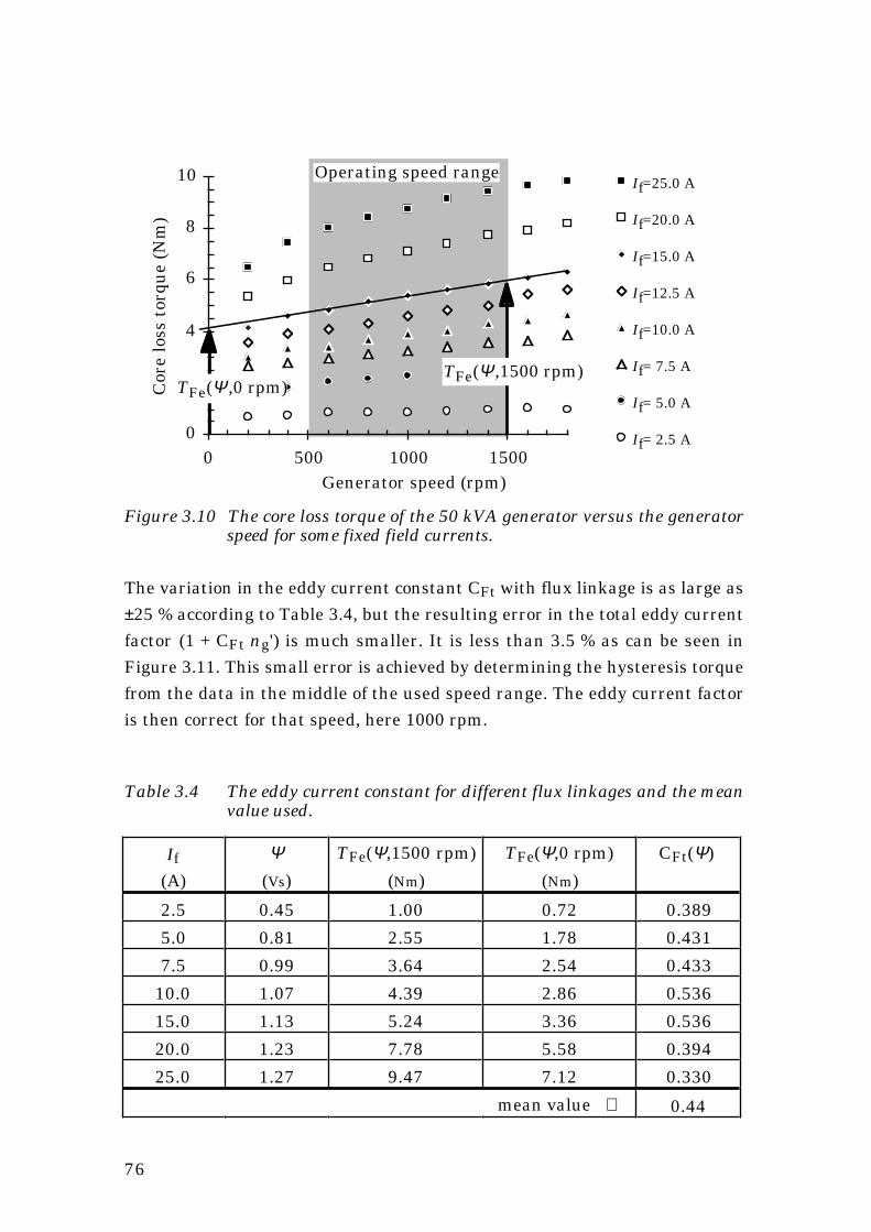
76
Generator speed (rpm)
Cor
e lo
ss t
orqu
e (N
m)
0
2
4
6
8
10
0 500 1000 1500
If=25.0 A
If=20.0 A
If=15.0 A
If=12.5 A
If=10.0 A
If= 7.5 A
If= 5.0 A
If= 2.5 A
Operating speed range
TFe(Ψ,0 rpm)TFe(Ψ,1500 rpm)
Figure 3.10 The core loss torque of the 50 kVA generator versus the generatorspeed for some fixed field currents.
The variation in the eddy current constant CFt with flux linkage is as large as±25 % according to Table 3.4, but the resulting error in the total eddy currentfactor (1 + CFt ng') is much smaller. It is less than 3.5 % as can be seen inFigure 3.11. This small error is achieved by determining the hysteresis torquefrom the data in the middle of the used speed range. The eddy current factoris then correct for that speed, here 1000 rpm.
Table 3.4 The eddy current constant for different flux linkages and the meanvalue used.
If
(A)
Ψ(Vs)
TFe(Ψ,1500 rpm)
(Nm)
TFe(Ψ,0 rpm)
(Nm)
CFt(Ψ)
2.5 0.45 1.00 0.72 0.389
5.0 0.81 2.55 1.78 0.431
7.5 0.99 3.64 2.54 0.433
10.0 1.07 4.39 2.86 0.536
15.0 1.13 5.24 3.36 0.536
20.0 1.23 7.78 5.58 0.394
25.0 1.27 9.47 7.12 0.330
mean value ⇒ 0.44

77
Generator speed (rpm)
Edd
y cu
rren
t fa
ctor
1
1,2
1,4
0 500 1000 1500
C
C
C
Ft min
Ft max
Ft
Figure 3.11 The error of the eddy current factor.
To find the relation between the hysteresis loss torque and the flux linkage,the core loss torque from the measurement above is used. The core losstorque is plotted versus the flux for one speed. The speed that should be usedis the one in the middle of the used speed range of the wind turbine generatorsystem. This is neccesary in order to reduce the error of assuming that all thetorque-speed lines have the same slope. For the 50 kVA generator the speedrange is 500 to 1500 rpm, and the hysteresis loss torque is thereforeapproximated from the loss torque at 1000 rpm. To reduce the absolute error,the values of the core loss torque should be taken from the straight lines thatalready have been used to approximate the eddy current factor, not directlyfrom measurements at 1000 rpm. The chosen core loss torque values do notonly contain the hysteresis torque but also the eddy current torque, in thiscase the eddy current torque of 1000 rpm. The eddy current loss torque isexcluded before the curve fit is made by using the formula for the relationbetween hysteresis losses and eddy current losses at different speeds
THy(Ψ) = TFe(Ψ,1000 rpm)
1 + 0.44
1000 rpm1500 rpm
(3.53)
After the division by the eddy current factor the hysteresis losses at ratedflux linkage can be found. The measured hysteresis loss torque as well as themodel of it is shown in Figure 3.12. The hysteresis loss torque may have avery steep increase when the flux exceeds the rated flux linkage.

78
The model parameter for the hysteresis loss torque of the 50 kVA generatoris
THy N = 3.47 Nm (3.54)
and in per unit the hysteresis loss torque is
tHy N = 1.15 % (3.55)
The parameter tFe N for the model can now be calculated
tFe N = tHy N ( 1 + CFt ) = 1.15 % ( 1 + 0.44 ) = 1.656 % (3.56)
Generator flux linkage (Vs)
Hys
tere
sis
torq
ue
(Nm
)
0
1
23
4
56
7
0,00 0,25 0,50 0,75 1,00 1,25
Ratedflux
Fe Nt
Figure 3.12 The model of and the measured hysteresis loss torque.
Armature resistance
For the 50 kVA generator the armature resistance is 66 mΩ per phase. The
resistive losses can then be expressed in per unit of the rated generatorpower as
ra = Pcu a NPg N
= 3 Ra Ia N2
Pg N = 2.54 % (3.57)

79
Field winding resistance
For the 50 kVA generator the field winding resistance is 1.37 Ω which make
the per unit field winding resistance
rf = Pcu f NPg N
= Rf If N2
Pg N = 1.04 % (3.58)
Exciter rotor resistance
The per phase resistance of the exciter armature was measured bydisconnecting the rotating diode rectifier
Ra E = 0.135 Ω (3.59)
ra E = Pcu E NPg N
= 2 Ra E If N2
Pg N = 0.21 % (3.60)
Additional losses
The additional losses in the generator are smaller than the measurementaccuracy of the laboratory system, which makes it difficult to trace themfrom single measurements. Instead the error of the loss model is plotted as afunction of armature current, when no additional losses are included in themodel. At resistive load no systematic correlation is found between the errorof the model and the armature current, see Figure 3.13. Thus the additionallosses can be assumed to be close to zero.
Armature current (A)
Pow
er e
rror
(W)
-500
-250
0
250
500
20 40 60 80
Figure 3.13 The model error at resistive load, when additional losses are notmodelled.

80
The additional losses at diode load are also small compared with themeasurement accuracy and can not be exactly determined, see Figure 3.14.Measurements at 1500 rpm show that the additional losses can be estimatedto about 320 W at rated armature current. The additional losses at diode loadcan be represented by an equivalent armature resistance
rad = Pad NPg N
= 0.67 % (3.61)
Dc current (A)
Add
itio
nal l
osse
s (W
)
-1200,0
-900,0
-600,0
-300,0
0,0
300,0
25 50 75 100
P ad N
Figure 3.14 The model error at diode load, when additional losses are notmodelled. The additional losses can be found as the current-dependent part of the loss model error. An approximation of theadditional losses is also shown as a line.
Error in the model for the 50 kVA generator
The total error in percent of the rated power is, according to Equation (3.42)
∆Ploss
PN = (0.14 % + 0.50 %) ng'+ (0.51 % + 0.34 %) ia2 + 0.21 % if2 (3.62)
The error expressed as a percentage of the rated shaft torque is, according toEquation (3.43)
∆Tloss
TN = 0.14 % + 0.50 % +
1ng' [ ]( )0.51 % + 0.34 % ia2 + 0.21 % if2
(3.63)

81
The maximum error in the loss model is, for the 50 kVA generator, about1.7 % of the rated generator power at rated load. The error of the calculatedshaft torque is also 1.7 % of the rated shaft torque.
3.4.3 Verification of the exciter losses
In Figure 3.15 the exciter losses plus field winding losses have been calculatedfrom the measurements. It can be seen that only the resistive losses in therotor must be included in the model.
Field current (A)
Rot
or a
nd e
xcit
er lo
sses
(W)
0
500
1000
1500
0 10 20 30
Exciter androtor losses
Calculatedresistiverotor losses
Figure 3.15 The losses of the exciter and main field winding versus main fieldcurrent.
3.4.4 Model error at resistive load
To find out how accurate the loss model is, first the error between the modeland the measured losses is calculated for the generator with resistive load. Inthe next section the same comparison is made for the generator loaded by adiode rectifier.
The losses are measured at all the combinations of five different generatorspeeds, five different armature currents and five different generator fluxlinkages. That is a total of 125 different load combinations that cover allpossible loadings of the generator. For each measurement the generatorspeed, shaft torque, field current, field winding voltage, armature voltage,armature current and electrical output power are measured. The model erroris defined as the shaft power or torque predicted by the model minus themeasured shaft power or torque.

82
For the resistivly loaded generator no additional losses are included in themodel. The torque error is always less than the total measurement error,±3 Nm. So, just by looking at the magnitude of the error it can not be judgedwhether the error depends on the model or the inaccuracy of themeasurement. But if the error is plotted versus for instance the generatorcurrent, the generator flux linkage or the speed it will be possible to see ifthere are any correlation between the errors and different quantities. Bylooking at how the error changes with a certain quantity, it shows if there aresystematic errors even if those errors are smaller than the stochastic ones.
The model torque error is plotted versus the generator shaft speed. It can beseen that the magnitude of the error is almost independent of the speed, seeFigure 3.16. The mean value of the model error is not perfectly zero for allspeeds but it is such a small correlation to the speed that it is well withinwhat should be expected.
Generator speed (rpm)
Tor
que
erro
r (N
m)
-3
-2
-1
0
1
2
3
500 1000 1500 2000
Figure 3.16 The torque error at resistive load and at different generator speeds.
The error plotted versus the generator flux linkage, Figure 3.17, shows adefinite correlation between the error and the flux linkage. At low generatorflux linkage the model underestimates the losses and at high flux linkage itoverestimates them. This is probably difficult to correct without a lot ofcalculations for each new generator to be modelled. However, the error is alsohere small and well within the desired accuracy of the model.
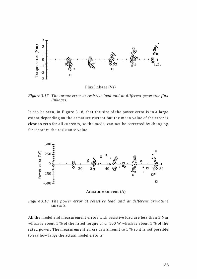
83
Flux linkage (Vs)
Tor
que
erro
r (N
m)
-3
-2
-1
0
1
2
3
0 0,25 0,5 0,75 1 1,25
Figure 3.17 The torque error at resistive load and at different generator fluxlinkages.
It can be seen, in Figure 3.18, that the size of the power error is to a largeextent depending on the armature current but the mean value of the error isclose to zero for all currents, so the model can not be corrected by changingfor instance the resistance value.
Armature current (A)
Pow
er e
rror
(W)
-500
-250
0
250
500
20 40 60 80
Figure 3.18 The power error at resistive load and at different armaturecurrents.
All the model and measurement errors with resistive load are less than 3 Nmwhich is about 1 % of the rated torque or or 500 W which is about 1 % of therated power. The measurement errors can amount to 1 % so it is not possibleto say how large the actual model error is.

84
3.4.5 Model error at diode load
When the generator is loaded by a diode rectifier the losses increase a littlecompared with resistive load. The increase is expected, since there will belosses in the damper windings that do not occur at resistive load. There willalso be more harmonics in the stator current leading to higher copper losses.Because of the larger proportion of high frequency components in the fluxdistribution the eddy current losses increase more than the hysteresis losses.
At resistive load the additional losses are low enough to be neglected. To takethe additional losses into account at diode load the model now includes afictitious armature resistance representing the additional losses. The error ofthe calculated shaft torque is plotted for different speeds, dc current, andgenerator flux linkage.
Figure 3.19 show the model torque error for some speeds, it can be seen thatthe error changes with the speed. The loss model underestimates the lossesat higher speeds which indicates that the eddy current losses have increasedcompared with no-load. The speed dependence of the error is larger than thatat resistive load: compare Figures 3.16 and 3.19.
Generator speed (rpm)
Tor
que
erro
r (N
m)
-6,0
-3,0
0,0
3,0
6,0
500 1000 1500 2000
Figure 3.19 The torque error at diode load and at different generator speeds.
Figure 3.20 shows no simple correlation between the generator flux linkageand the torque error. The correlation is different from that at resistive load,compare Figures 3.17 and 3.20. The difference may depend only on the factthat there are different ways of calculating the flux linkage with resistive loadand with diode load.

85
Flux linkage (Vs)
Tor
que
erro
r (N
m)
-6,0
-3,0
0,0
3,0
6,0
0 0,25 0,5 0,75 1 1,25
Figure 3.20 The torque error at diode load and at different generator fluxlinkages.
The armature current clearly effect the magnitude of the power error in thesame way as it does at resistive load, compare Figures 3.18 and 3.21.Although the additional losses are taken into account, the model is not asaccurate at diode load as it is at resistive load. The total error whencomparing model and measurements is, for a diode-loaded generator, up to2 % of the rated power or torque. The measurement error can contribute withno more than 1 %.
Dc current (A)
Pow
er e
rror
(W)
-900,0
-600,0
-300,0
0,0
300,0
25 50 75 100
Figure 3.21 The error in estimated power at different dc currents.
3.4.6 Error in the torque control
The loss model can be used for torque control of the generator. The error ofsuch a torque control is easiest found if the torque error of the model is plottedwith the measured shaft torque as a parameter. Since the model is intended

86
for use in a variable speed wind turbine generator system only the error atdiode load is presented here. In Figure 3.22 the torque error is plotted for allpossible combinations of speed, armature current and flux linkages.
Shaft torque (Nm)
Tor
que
erro
r (N
m)
-6,0
-3,0
0,0
3,0
6,0
100 200 300
Figure 3.22 The error, at diode load, in the calculated torque compared withthe actual torque, for all possible combinations of speed, armaturecurrent and flux linkages.
In this comparison of torque error versus shaft torque the error is almostzero at zero torque, but this is because the parameters for the friction lossesand core losses are measured. If they were estimated with an error, thatwould show as an offset error at zero shaft torque. The error decreases for lowshaft torque, but not linearly with the torque. This means that the total errorwill never be more than about 2 % of the rated generator torque but therelative torque error can be larger than 2 % at part load.
In a wind turbine generator system not all of the above measured loadcombinations are realistic. For instance, high current at high flux linkage andlow speed will never occur. Since the most extrem load combinations have thelargest errors it is interesting to find the error of only the load combinationsthat will be used in a wind turbine generator system. These loadcombinations follow the torque-speed curve of the optimum load of a windturbine. For wind turbine loads it can be seen that the model error is generallysmaller than for other loadings, see Figure 3.23. Large errors only occur withlow flux linkage combined with high current, probably due to armaturereaction effects. If these low magnetizations are avoided the maximum errorwill be less than 1 % percent for the 50 kVA generator.

87
Shaft torque (Nm)
Tor
que
erro
r (N
m)
-8
-6
-4
-2
0
2
4
100 200 300
Normal flux linkage
Low flux linkage and high armature reaction
Figure 3.23 The torque error of the model with normal wind turbine loads.Normal flux linkage (filled dots) and low flux linkage and higharmature reaction (unfilled dots).
3.5 Model for the 300 kW design example
In the following chapters, the loss model is used in the design of the systemand to calculate the average efficiency of the generator and convertersystem. These calculations are made for the 300 kW design example systemand here the parameters for that system are derived.
3.5.1 Generator parameters
For the 300 kW generator with exciter the loss model can be determinedmainly by data from the manufacturer [12], but also with estimations basedon scaling of known data. In Table 3.5 the 50 and 60 Hz data from thegenerator manufacturer are presented. The data are also recalculated for thelower rated current and voltage used in the design example system. Someparameters have only been estimated.
The parameters of the simplified loss model for the 300 kW generator cannow be determined. The friction and windage torque parameters areestimated to
tµ N = 0.66 % (estimated) (3.64)tµ ss = 0.22 % (estimated) (3.65)

88
Table 3.5 Data for the design example generator. Data are available forclass H loading at 50 and 60 Hz and those are recalculated for theratings used in the design example.
Data forsynchronous gen.
LSA 47.5 M4
50 Hz1500 rpm
60 Hz1800 rpm
design example 1800 rpm
Temperature rise class H class H class BSa N 350 kVA 420 kVA 334 kVAPg N ≈320 kWIa N 505 A 505 A 410 A
Ua N / nN 400 V/1500rpm
480 V/1800rpm
475 V/1800rpm
Ploss 0 (No load losses) 5400 W 7600 W 7600 Wxd" 13.7 % 14.3 % 11.7 %xq" 17.4 % 18.1 % 14.8 %
Ra (at 50˚ C) 0.0128 Ω 0.0128 Ω 0.0128 Ωxs ≈ xd 355 % 370 % 304 %
Estimated losses:
ng N TµN 1480 W / 0.4 % 2100 W / 0.48 % 2100 W / 0.66%
Pad N 1940 W / 0.52%
1940 W / 0.44 % 1280 W / 0.4 %
PCu f N 4200 W / 1.2 % 4200 W / 0.95 % 2900 W / 0.9 %
The field winding losses at no load are very small even at rated flux. The largesynchronous reactance makes the no load field current only about 25 % ofthe rated field current. Therefore, the field winding losses at no load, pCu f 0,are only 6 % of the field winding losses at rated load and they are neglected.The core loss torque at rated flux can be determined approximately from theno load losses as
tFe N = ploss 0 – pCu f 0
n'g N – tµ N = pCu f 0 ≈ 0 ≈ 1.72 % (3.66)
No value of CFt has been found and for this example it is estimated to be
CFt = 0.5 (estimated) (3.67)

89
ra = 3 Ra Ia N
2 Pg N
= 2.02 % (3.68)
rad = Pad N Pg N
= 0.40 % (estimated) (3.69)
rf = PCu f N Pg N
= 0.90 % (3.70)
Rr com = 12 xr com =
12
xd" + xq"2 = 6.58 % (3.71)
xs = 304 % (3.72)
3.5.2 Converter parameters
For the design example system the converter losses are in Chapter 2 found tobe
ploss c(id) = 0.12 % + (0.52+0.33) % id + (0.10+0.70+0.17) % id2 (3.73)
The converter efficiency at rated load is 98 %.
3.5.3 Gear parameters
A gear in the 300 kW range would have gear mesh losses of about 1 % foreach stage and friction losses of about 0.5 % at rated load and at rated speed.In this model the gear friction torque is assumed to be constant. The brakingtorque of the gear losses, for a gearbox of 97 % rated efficiency, is
tloss gear(tt) = 0.5 % + 2.5 % tt (3.74)
where tt is the turbine shaft torque in per unit.

90
4 The use of the loss model in control and design
In this chapter, the system efficiency is optimized. The model of losses in thegenerator and converter can be used to maximize the efficiency of the systemduring operation. The system design can also be optimized by comparingdifferent generators of various rated power and rated speed.
4.1 Optimum generator voltage control
The frequency converter does not only allow variations in the generatorfrequency. It also allows variations of the generator voltage. In a wind turbinegenerator system the optimum shaft torque is pre-determined as a functionof speed. The optimum torque can, however, be obtained by differentcombinations of generator current and voltage. This control possibility can beused to minimize the generator and converter losses by means of the voltagecontrol.
The maximum allowed generator voltage is limited by the inverter ac voltageat full load and at low load and low speed by the maximum allowed generatorflux. At full load the generator voltage is limited to 90 % of the inverter acvoltage to insure safe commutation of the inverter. At low load and low speedthe generator flux has to be lower than 105 % of the rated generator flux andthis limits the generator voltage. According to standards the generator mustbe able to continuously operate at a flux 5 % higher than the rated value [13].On the other hand, the generator voltage may not be so low that thearmature current increases above its rated value. Within these limits, thevoltage can be controlled freely.
The generator core losses decrease with decreasing flux and the armaturecopper losses decrease with decreasing current. Also the field winding losseschange with the flux. If the armature reaction is small, the field windinglosses will decrease with decreasing voltage, and if it is high the field windinglosses will increase with decreased voltage. The increase in field windinglosses at high armature reaction occurs because the field current mustincrease to balance the increasing armature currents even though thevoltage is decreased. Also the efficiency of the converter changes with thevoltage. Since most of the losses are due to voltage drops of thesemiconductors and resistive voltage drops of the dc filter, the losses increasewith increasing current. For a fixed power the converter losses thus increasewith decreasing voltage. The generator voltage should be controlled to

91
minimize the sum of core losses, field winding losses, copper losses andconverter losses, see Figure 4.1.
0.2 0.4 0.6 0.8 1
Dc voltage (p.u.)
0
0.01
0.02
0.03
0.04
0.05
Gen
erat
or a
nd
con
vert
er lo
sses
(p.
u.)
Total losses
Armature losses
Converter losses
Field winding losses
Core losses
Optimumvoltage
Figure 4.1 The core losses, field winding losses, armature copper losses,converter losses and the total losses versus dc voltage at a fixedspeed and power.
In Figure 4.2 the total generator and converter efficiency versus the inputpower of the generator can be seen both when an optimized voltage control isused and when the flux is kept constant at the rated flux.
From the loss model the optimum voltage-speed curve can be calculatedtheoretically. This curve is together with the voltage limits shown inFigure 4.3. If low voltages are used, there may be problems with the voltagecontrol even if the current is not higher than the rated current. Theseproblems arise because the armature reaction eventually becomesdominating in the generator voltage control. Normally, the voltage is reducedby reducing the field current. At the same time, the armature current isincreased to keep the shaft torque constant. But, if the armature reaction islarge, it may be necessary to raise the field current when the armaturecurrent is increased even though the voltage is reduced. The coupling betweenthe voltage control and the current control may in that case cause problems.

92
0.2 0.4 0.6 0.8 1
Generator input power (p.u.)
0.65
0.7
0.75
0.8
0.85
0.9G
ener
ator
an
d co
nve
rter
eff
icie
ncy
Optimized voltage control
Constant rated flux
Figure 4.2 The generator and converter efficiency versus generator inputpower using an optimized voltage control and using constantrated flux.
0.2 0.4 0.6 0.8 1
Wind speed (p.u.)
0
0.2
0.4
0.6
0.8
1
Gen
erat
or v
olta
ge (
p.u
.)
Maximum voltage
Minimum voltage
Voltage at maximum efficiency
Figure 4.3 The maximum, optimum and minimum voltage of the generatorin a variable speed wind turbine generator system.
4.2 Efficiency as a function of generator size
The generator rating should be chosen to minimize the total cost of both thegenerator and its losses. A large generator may be the most economic choice,even though it is more expensive, if it is more efficient.

93
When comparing data for different sizes of the same generator type, e.g. forLeroy Somer generators [12], it can be seen that the different per unit lossesdo not always decrease when the size of the generator increases, because thegenerators are made in different standard frame sizes. Increasing the ratedefficiency is not always done by increasing the generator frame size. Whencomparing the losses between two close generator sizes the smallergenerator may, therefore, sometimes have lower armature resistancealthough its rated current is smaller. But only on very rare occasions it canbe found that a generator has a lower rated efficiency than one that issmaller.
The efficiency of three generators of different sizes is compared. It isassumed that they have the same efficiency at their respective ratedpowers. The generator sizes are chosen so that one generator will have arated power of only 80 % of the wind turbine generator system maximumpower. The rated power of the next generator is 100 % and of the lastgenerator 120 % of the maximum turbine power. In Figure 4.4 the efficiencyis plotted and it is clear that an oversized generator does not have higherefficiency if the per unit losses are equal. An undersized generator has thehighest efficiency but it can of course not be used because it will beoverloaded. A larger generator will give a higher efficiency only if the increaseof rated efficiency is larger than the decrease in efficiency by reducing thegenerator per unit load. At a certain power the difference in efficiencybetween generators of different sizes can generally be expected to be small.
An other reason to use a larger generator than necessary would be, besides ahigher generator efficiency, that the insulation limit the generator life. Sincethe generator in a wind turbine generator system should have a very longoperational life compared with many motor applications, the rating for thetemperature class H or F may be too high leading to isolation failure afterless than 20 to 30 year. A generator, made with class H insulation, caninstead be used with a rated power that only leads to temperature risesaccording to class B to increase the life of the insulation. This is the same asusing a larger generator for a specific power.

94
0.2 0.4 0.6 0.8 1
Generator input power (p.u.)
0.88
0.89
0.9
0.91
0.92
0.93
0.94G
ener
ator
eff
icie
ncy
20% larger generator
Normal generator size
20% smaller generator
Figure 4.4 The efficiency of generators of different rated power.
4.3 Optimum generator speed
For network-connected ac generators only some few fixed speeds can be used.These speeds are determined by the network frequency and the number ofpole pairs of the generator. For a 50 Hz network the available speeds are3000, 1500, 1000, 750 rpm and lower.
For a variable-speed wind turbine generator system the choice of thegenerator speed is not restricted to a choice of pole pair number. Thefrequency of the generator can also be chosen freely which allows anygenerator speed. For instance, a four-pole generator can either be used at1200 rpm and a frequency of 40 Hz or at 1800 rpm and 60 Hz. A six-polegenerator can also be used at 1800 rpm and the frequency is then 90 Hz.
Even though the turbine speed is determined by its optimum tip-speed ratio,the speed of the generator can be changed by using different gear ratios.From the loss model it can be found how the efficiency change with thegenerator speed. The change in efficiency when the speed is changed dependon how the power and generator flux are changed with the speed. Twocomparisons are made. First the generator efficiency is calculated at variousspeeds but at constant power and secondly the generator efficiency iscalculated when it is loaded as much as possible at each speed.

95
When the power of the generator is the same at all different speeds thearmature voltage can be kept constant. If the voltage is constant, the flux ofthe generator will be approximately inversely proportional to the speed of thegenerator. The power being constant as well as the voltage leads to aconstant armature current. The friction and windage losses increase almostby the speed raised to a power of three. Armature winding copper lossesremain constant in this example since the current is constant. The flux is,however, reduced which reduces the hysteresis losses. Also the eddy currentlosses are reduced but not as much as the hysteresis losses. Field windinglosses are reduced too, because of the reduced flux.
The efficiency can, however, be better optimized by controlling the voltage tomaximize the efficiency for each generator speed. Calculations on theefficiency with this type of control are also made. The armature current isnow decreased a little as the speed increase since the voltage may increase.Not only the core losses and field winding losses decrease but also thearmature copper losses.
The loss model of the generator is used to calculate the efficiency versus thespeed of the generator at a fixed input power. The resulting efficiency for the50 kVA generator used at a constant voltage or at a voltage controlled tomaximize the efficiency can be seen in Figure 4.5.
1 1.2 1.4 1.6 1.8 2
Generator speed (p.u.)
0.91
0.92
0.93
0.94
0.95
Gen
erat
or e
ffic
ien
cy
Maximum efficiency
Constant voltage
Figure 4.5 The theoretical efficiency of the 50 kVA generator at a constantpower.

96
In the diagram it can be seen that the efficiency of the 50 kVA generator atdiode load has its peak value for a speed of 1.1 p.u., if the voltage and powerare both kept constant. The efficiency is then 93.7%. If the efficiency isoptimized by raising the voltage, the efficiency can be even higher, 94.1%,and have its peak value at 1.25 p.u. speed. It is clear that the generatorspeed should be kept high to increase efficiency. A realistic limit is probably1800 rpm, that is equal to 1.2 p.u.
The speed dependency of the generator efficiency will not be the same if thepower of the generator is allowed to increase with the speed, see Figure 4.6.This calculation is interesting because it shows how the generator efficiencychanges if the generator is always maximally utilized. To avoid overcurrent inthe windings the voltage must at least be raised proportionally to thegenerator speed, corresponding to a constant flux.
1 1.5 2 2.5
Generator speed (p.u.)
0.91
0.92
0.93
0.94
0.95
Gen
erat
or e
ffic
ien
cy
Maximum efficiency
Constant flux
Figure 4.6 The theoretical maximum efficiency of the 50 kVA generator at itsmaximum power.
If the generator is fully utilized, the efficiency will be even higher than if thepower is kept at its rated value for 1500 rpm. The maximum efficiency is94.6 % but it is at a speed far too high for ordinary generators, 2.2 p.u. Usingrated generator flux the maximum generator efficiency is only slightly lowerand at a speed of 2.05 p.u. These theoretical maximum efficiencies cannot bereached because the generator will be overloaded. It is, however, clear that ahigh speed and a high utilization increase generator efficiency.
The results above show how the generator efficiency changes with thegenerator speed. The converter efficiency does not depend on the speed of the

97
generator, only on the rated voltage. The rated voltage is determined by thenetwork voltage and therefore the converter efficiency is not dependingdirectly on the rated speed of the generator. The change in rated generatorspeed must instead be compensated by changing the voltage rating of thegenerator windings to fit the converter voltage. The theoretical generator andconverter efficiency is plotted for different generator speeds in Figure 4.7.
0.2 0.4 0.6 0.8 1
Generator input power (p.u.)
0.82
0.84
0.86
0.88
0.9
0.92
0.94
Gen
erat
or a
nd
con
vert
er
e
ffic
ien
cy
= 0 - 1.2 p.u.
= 0 - 1.0 p.u.
= 0 - 0.8 p.u.
n'
n'
n'
Figure 4.7 The maximum theoretical efficiency of the 50 kVA generator andconverter system for various rated speeds.
To verify what difference the generator speed makes, the efficiency of thegenerator and converter system was measured using speed-power functionsrepresenting three different gear ratios. The maximum speeds were 1393rpm, 1500 rpm and 1700 rpm and the maximum power were 42.1 kW for allthree gear ratios. The maximum efficiency of the electrical system for thesethree gear ratios is compared in Figure 4.8.
It is also clear from these measurements that the efficiency of a generatorconverter system increases if higher generator speed can be used. Thedifference in efficiency is about 1% for the 50 kVA system when comparing1500 rpm with 1700 rpm. This difference between different speeds is verylarge, mainly because of the low efficiency of the laboratory converter. Amore efficient generator converter system will also have higher efficiency athigher speed, but the difference should not be expected to be larger than sometenths of a percent.

98
Power to the grid (W)
Tot
al e
ffic
ien
cy
0,8
0,85
0,9
0 10000 20000 30000 40000
500-1393 rpm
500-1500 rpm
567-1700 rpm
Figure 4.8 The measured maximum efficiency of the 50 kVA generator andconverter system for three different gear ratios.
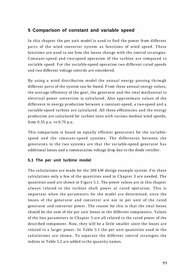
99
5 Comparison of constant and variable speed
In this chapter the per unit model is used to find the power from differentparts of the wind converter system as functions of wind speed. Thesefunctions are used to see how the losses change with the control strategies.Constant-speed and two-speed operation of the turbine are compared tovariable speed. For the variable-speed operation two different rated speedsand two different voltage controls are considered.
By using a wind distribution model the annual energy passing throughdifferent parts of the system can be found. From these annual energy values,the average efficiency of the gear, the generator and the total mechanical toelectrical power convertion is calculated. Also approximate values of thedifference in energy production between a constant-speed, a two-speed and avariable-speed turbine are calculated. All these efficiencies and the energyproduction are calculated for turbine sites with various median wind speeds,from 0.35 p.u. to 0.70 p.u.
This comparison is based on equally efficient generators for the variable-speed and the constant-speed systems. The differences between thegenerators in the two systems are that the variable-speed generator hasadditional losses and a commutation voltage drop due to the diode rectifier.
5.1 The per unit turbine model
The calculations are made for the 300 kW design example system. For thesecalculations only a few of the quantities used in Chapter 3 are needed. Thequantities used are shown in Figure 5.1. The power values are in this chapteralways related to the turbine shaft power at rated operation. This isimportant when the parameters for the model are determined, since thelosses of the generator and converter are not in per unit of the ratedgenerator and converter power. The reason for this is that the total lossesshould be the sum of the per unit losses in the different components. Valuesof the loss parameters in Chapter 3 are all related to the rated power of thedescribed component. Now, they will be a little smaller since the losses arerelated to a larger power. In Table 5.1 the per unit quantities used in thecalculations are shown. To separate the different control strategies theindices in Table 5.2 are added to the quantity names.

100
n't = n' = n'g
pt pg pa pi
v
ua
Figure 5.1 The quantities used in the per unit calculations in Chapter 5.
Table 5.1 Per unit quantities and constants used in this chapter and thebase values.
Quantity Notation Base value
Per unit wind speed v vN
Per unit start wind speed v0 vN
Per unit wind speed of rated power vN vN
Max operational per unit wind speed vmax vN
Per unit median wind speed vm vN
Per unit turbine power pt Pt N
Per unit generator speed (= turbine speed) n' ng N (nt N)
Per unit generator mechanical power pg Pt N
Per unit armature voltage uaPa N
√ 3 Ia N
Per unit generator electrical power pa Pt N
Per unit power from the inverter pi Pt NPer unit power losses ploss Pt NPower coefficient CP CP max
Per unit annual energy capture of the turbine et Pt N 8760 h*
Per unit annual input energy of the generator eg Pt N 8760 h*
Per unit annual output energy from the gen. ea Pt N 8760 h*
Per unit annual output energy from the inverter ei Pt N 8760 h*
Per unit Weibull probability density w —
*) one year is 8760 hours.
101
Table 5.2 The indices used for the constants and functions in this chapter.
Indices Notation
Constant speed CS
Two speeds TS
Low speed (of two) TS1
High speed (of two) TS2
Variable speed VS
Variable speed, 1.2 p.u. rated speed VS12
Optimum voltage control VSopt
Optimum voltage control with 1.2 p.u. as rated speed VSopt12
5.2 Power and losses as functions of the wind speed
5.2.1 Assumptions for the power functions
It is assumed that the wind turbine generator system is designed for acertain mechanical power from the wind turbine. When comparing theconstant-speed system with the variable-speed system, the maximum inputpower from the turbine is the same but not the output power to the grid. Thevariable-speed system thus has a little lower rated electric power than theconstant-speed system due to increased generator losses and the converterlosses. The rated generator input power is, however, the same in both theconstant-speed system and the variable-speed system because the gearlosses at rated power are equal for both systems.
To be able to find the difference between a variable-speed and a constant-speed system, without including the different efficiency of different generatortypes, it is assumed that the generator used in the constant-speed system isthe same as the one used in the variable-speed system. However, since thevariable-speed generator is connected to a frequency converter, it has higherlosses compared with the network-connected generator. The voltage drop ofthe variable-speed generator is also higher due to the diode commutations.
The efficiency of the two-speed generator is based on efficiency data for a 250kW/75 kW 4/6-pole ABB induction generator and not on the loss model. Thatloss data have been modified to be comparable to the losses of the 300 kWdesign example generator. When compared with generators of the same sizebut with only one speed the efficiency is roughly 1 % lower for a two-speed

102
generator. Such a difference is included in this comparison as a 0.7 % lowerefficiency at rated power for the two-speed generator than for the constant-speed generator.
Since all functions will be expressed with the wind speed as a parameter, theturbine speed as a function of the wind speed must be defined. That is simplefor the cases considered in this report. Either the wind turbine runs atconstant speed with a rated speed of 1 p.u. and a low speed for the two-speedgenerator equal to 2/3 p.u. or variable speed with optimal CP control is usedand the tip-speed ratio is kept constant. Hence the turbine speed isproportional to the wind speed up to the rated wind speed. Above the ratedwind speed the turbine speed is assumed to be kept constant.
n'CS = 1 (Speed of the constant-speed generator) (5.1)
n'TS1 = 23 (Low speed of the two-speed generator) (5.2)
n'TS2 = 1 (High speed of the two-speed generator) (5.3)
n'VS(v) = v (Speed of the variable-speed generator) (5.4)
n'VSopt12(v) = 1.2 v (Higher variable speed) (5.5)
The generator is started as soon as the wind speed is high enough for theturbine to produce more than the total system losses. These include losses inthe gear plus generator and for the variable-speed system also the converterno-load losses. The start-up wind speed is not the same for the differentcontrol strategies because the losses are different. The start-up wind speedcan for the constant- and two-speed systems be found as the lowest windspeed for which the generator output power is zero. At a lower wind speed theno load losses will make the generator power negative. The start-up windspeed v0 is found by solving the following equation
pa(v0) = 0 (5.6)
The two-speed system changes speed at the wind speed for which the higherspeed produces as much power as the lower speed. This wind speed v0TS2 isfound by solving the following equation
103
paTS1( v0 TS2 ) = pa TS2( v0 TS2 ) (5.7)
For the variable-speed system the start-up wind speed is found as the lowestwind speed for which the output power of the inverter is zero
pi( v0 VS ) = 0 (5.8)
The rated wind speed of the turbine is here defined as the lowest wind speedat which the turbine can produce rated power. This wind speed is used asbase quantity for the per unit wind speeds. The rated wind speed of thecomplete wind turbine generator system depend on how the turbine speed iscontrolled. With the used definition of the rated wind speed the constant-speed turbine reaches rated power at a wind speed above 1 p.u. The reasonfor this is that the gear ratio is chosen to maximize the turbine efficiency at awind speed of about 0.7 p.u. to maximize the energy production. The variable-speed turbine also reaches the rated power at a wind speed slightly higherthan 1 p.u., because it is not assumed possible to keep the turbine perfectlyat its optimum tip-speed ratio.
The rated wind speeds for the different systems, vN, are found by solving thefollowing equation:
pt( vN ) = 1 (5.9)
The turbine is shut down when the wind speed exceeds 1.7 p.u.
vmax = 1.7 p.u. (5.10)
The start-up wind speed, rated wind speed and shutdown wind speed for thedifferent systems are found in Table 5.3.
To be able to use the model the turbine power coefficient as a function of tip-speed ratio must first be modelled. Data are used for a three-bladed pitch-controlled 12 m turbine. The approximate turbine CP curve is a sixth-ordercurve fit and can be seen in Figure 5.2.

104
Table 5.3 The start-up wind speed, speed-change wind speed, rated windspeed and shutdown wind speed for different systems.
CS TS VS VSopt VSopt12
v0 0.38 0.29 0.20 0.18 0.18
v0TS2 – 0.62 – – –
vN 1.05 1.05 1.01 1.01 1.01
vmax 1.70
2.5 5 7.5 10 12.5 15
Tip-speed ratio
0
0.1
0.2
0.3
0.4
0.5
Tu
rbin
e po
wer
coe
ffic
ien
t
Figure 5.2 Approximation of the power coefficient curve of the turbine.
In the variable-speed system the generator speed is controlled to keep theturbine power coefficient CP at its maximum value for all wind speeds.However, the turbine speed can not change as fast as the wind speed and,therefore, the turbine can not keep a constant maximum CP. To include thiseffect in the calculations without making dynamic simulations the variable-speed turbine is supposed to maintain an average CP a little lower than themaximum CP. A lower average CP means a loss of energy production. Themagnitude of this energy loss depends on the control of the turbine. A study ofthe optimum control of a wind turbine has been made and it shows that witha shaft torque variation of about 20 % the mean power loss is only about2.5 %, [14]. This is only an estimation of the average CP but the error of theestimation does not affect the calculated average efficiencies much. Theaccuracy of the calculated energy production is on the other hand directlyaffected by the error in average CP.

105
5.2.2 Power functions
First the parameters of the gear loss model, the generator loss model and theconverter loss model must be determined. This is done by using the results inChapter 3.
Now the turbine energy-capture function, pt(v), can be calculated. It isdifferent for the variable-speed turbine, the two-speed turbine and theconstant-speed turbine. Therefore, different power functions are defined forthe different systems. For the two-speed system two different functions areused. In the CP function the tip-speed ratio, λ, is replaced by
λ = C n'
v (5.11)
where C is a constant determined by the rated wind speed vN the turbinediameter dt and the rated turbine speed nt N. The constant is
C = nt N π dt
vN(5.12)
The turbine power functions pt(v) can now be expressed, below rated power,as
pt(v) = v3 Cp
C n'(v)v (5.13)
where Cp(λ) is the approximation of the turbine power coefficient curve.Then the output power of the gear pg(v) is calculated
pg(v) = pt(v) – ploss gear( pt(v) , n'(v) ) (5.14)
where ploss gear( pt , n' ) is the losses of the gear.
The losses of the generator are defined by the loss model with armaturevoltage, armature current and shaft speed as variables. The armaturecurrent is, however, not known yet. Therefore, the generator losses can notbe calculated explicitly. Instead, the output power of the generator is
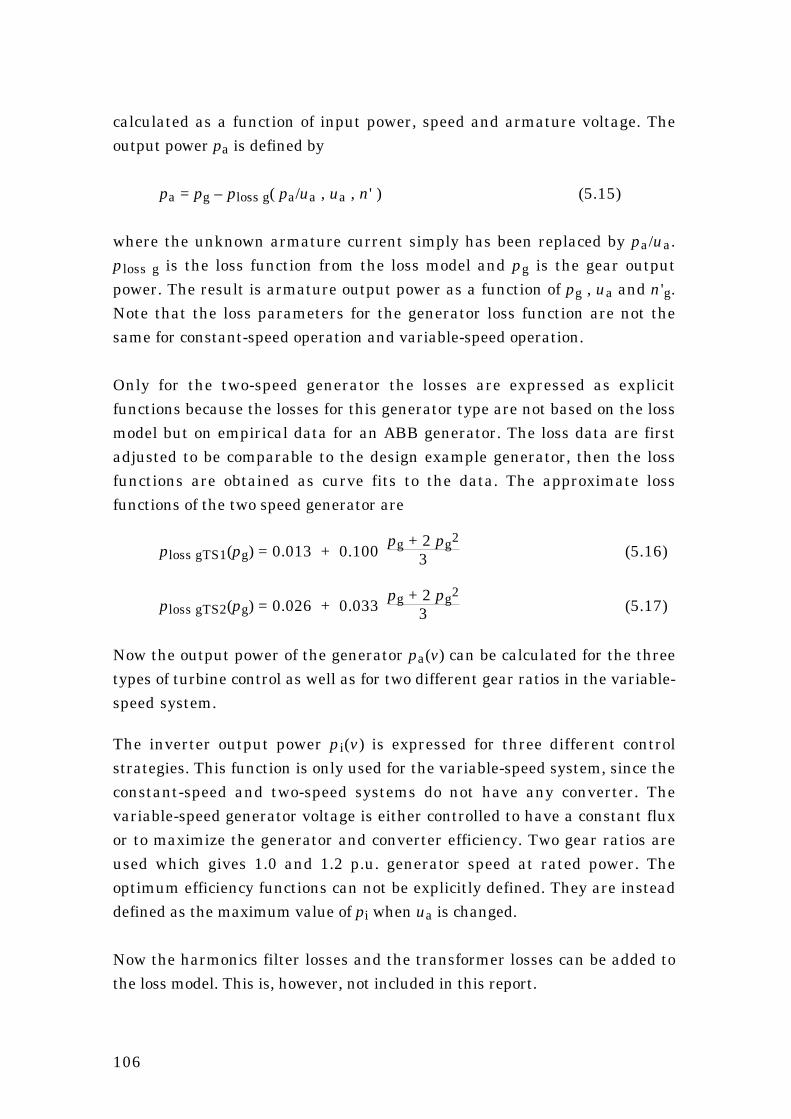
106
calculated as a function of input power, speed and armature voltage. Theoutput power pa is defined by
pa = pg – ploss g( pa/ua , ua , n' ) (5.15)
where the unknown armature current simply has been replaced by pa/ua.ploss g is the loss function from the loss model and pg is the gear outputpower. The result is armature output power as a function of pg , ua and n'g.Note that the loss parameters for the generator loss function are not thesame for constant-speed operation and variable-speed operation.
Only for the two-speed generator the losses are expressed as explicitfunctions because the losses for this generator type are not based on the lossmodel but on empirical data for an ABB generator. The loss data are firstadjusted to be comparable to the design example generator, then the lossfunctions are obtained as curve fits to the data. The approximate lossfunctions of the two speed generator are
ploss gTS1(pg) = 0.013 + 0.100 pg + 2 pg2
3 (5.16)
ploss gTS2(pg) = 0.026 + 0.033 pg + 2 pg2
3 (5.17)
Now the output power of the generator pa(v) can be calculated for the threetypes of turbine control as well as for two different gear ratios in the variable-speed system.
The inverter output power pi(v) is expressed for three different controlstrategies. This function is only used for the variable-speed system, since theconstant-speed and two-speed systems do not have any converter. Thevariable-speed generator voltage is either controlled to have a constant fluxor to maximize the generator and converter efficiency. Two gear ratios areused which gives 1.0 and 1.2 p.u. generator speed at rated power. Theoptimum efficiency functions can not be explicitly defined. They are insteaddefined as the maximum value of pi when ua is changed.
Now the harmonics filter losses and the transformer losses can be added tothe loss model. This is, however, not included in this report.
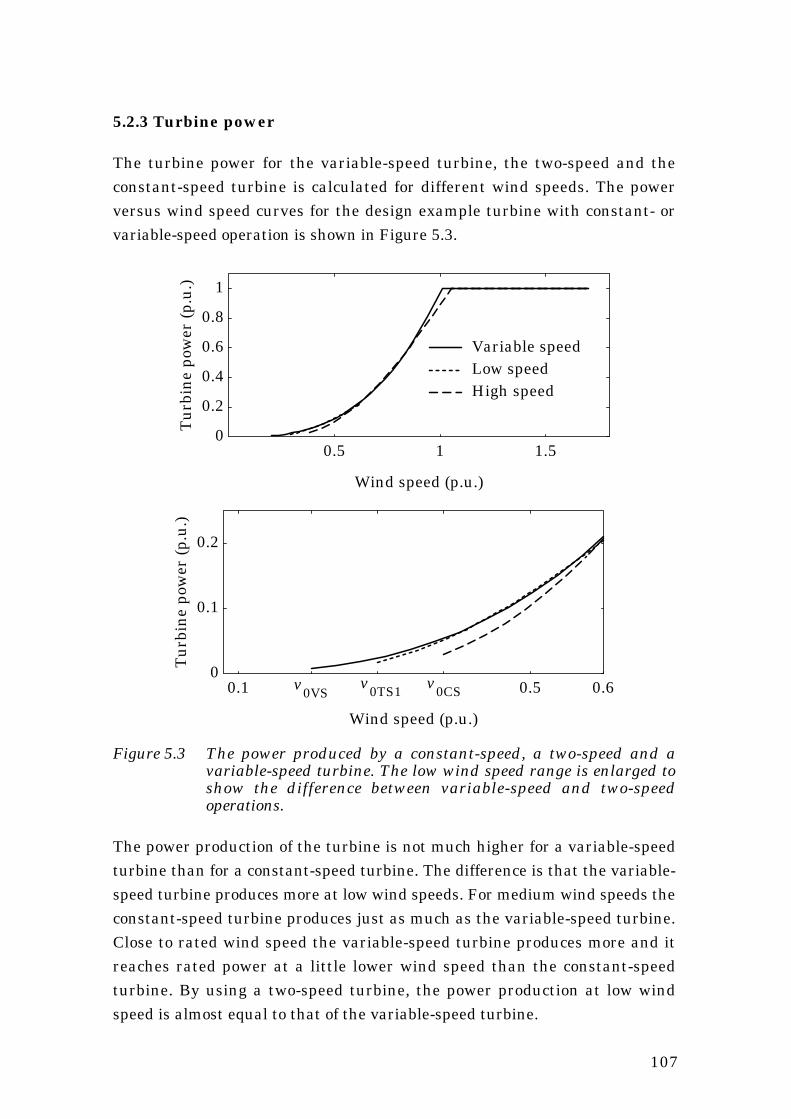
107
5.2.3 Turbine power
The turbine power for the variable-speed turbine, the two-speed and theconstant-speed turbine is calculated for different wind speeds. The powerversus wind speed curves for the design example turbine with constant- orvariable-speed operation is shown in Figure 5.3.
0.5 1 1.5
Wind speed (p.u.)
0
0.2
0.4
0.6
0.8
1
Tu
rbin
e po
wer
(p.
u.)
Variable speedLow speedHigh speed
0.1 0.5 0.6
Wind speed (p.u.)
0
0.1
0.2
Tu
rbin
e po
wer
(p.
u.)
v0VSv0TS1 v0CS
Figure 5.3 The power produced by a constant-speed, a two-speed and avariable-speed turbine. The low wind speed range is enlarged toshow the difference between variable-speed and two-speedoperations.
The power production of the turbine is not much higher for a variable-speedturbine than for a constant-speed turbine. The difference is that the variable-speed turbine produces more at low wind speeds. For medium wind speeds theconstant-speed turbine produces just as much as the variable-speed turbine.Close to rated wind speed the variable-speed turbine produces more and itreaches rated power at a little lower wind speed than the constant-speedturbine. By using a two-speed turbine, the power production at low windspeed is almost equal to that of the variable-speed turbine.
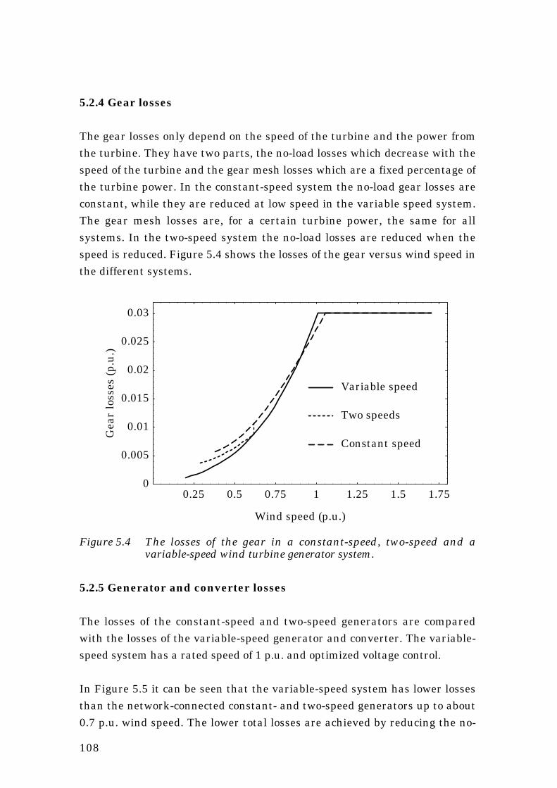
108
5.2.4 Gear losses
The gear losses only depend on the speed of the turbine and the power fromthe turbine. They have two parts, the no-load losses which decrease with thespeed of the turbine and the gear mesh losses which are a fixed percentage ofthe turbine power. In the constant-speed system the no-load gear losses areconstant, while they are reduced at low speed in the variable speed system.The gear mesh losses are, for a certain turbine power, the same for allsystems. In the two-speed system the no-load losses are reduced when thespeed is reduced. Figure 5.4 shows the losses of the gear versus wind speed inthe different systems.
0.25 0.5 0.75 1 1.25 1.5 1.75
Wind speed (p.u.)
0
0.005
0.01
0.015
0.02
0.025
0.03
Gea
r lo
sses
(p.
u.)
Constant speed
Two speeds
Variable speed
Figure 5.4 The losses of the gear in a constant-speed, two-speed and avariable-speed wind turbine generator system.
5.2.5 Generator and converter losses
The losses of the constant-speed and two-speed generators are comparedwith the losses of the variable-speed generator and converter. The variable-speed system has a rated speed of 1 p.u. and optimized voltage control.
In Figure 5.5 it can be seen that the variable-speed system has lower lossesthan the network-connected constant- and two-speed generators up to about0.7 p.u. wind speed. The lower total losses are achieved by reducing the no-

109
load losses of the generator by the voltage control. At high wind speed, thevariable-speed system has higher losses than the network-connectedgenerators due to the losses in the frequency converter and additionalgenerator losses.
0.25 0.5 0.75 1 1.25 1.5 1.75
Wind speed (p.u.)
0
0.02
0.04
0.06
0.08
Gen
erat
or a
nd
con
vert
er lo
sses
(p.
u.)
Variable speed
Two speeds
Constant speed
Figure 5.5 The losses of the constant-speed and two-speed generatorscompared to the generator and converter losses of the variable-speed system.
A two-speed generator can not be utilized fully for both speeds and thereforeit has higher losses than the constant-speed generator when it runs on thehigh speed. At the low speed the two-speed generator has lower lossesbecause the friction, windage and core losses are reduced.
5.2.6 Losses at different voltage controls
The variable-speed system can be controlled in different ways. The voltagecontrol can be used to minimize the losses of the generator and converter.The effect of such an optimization is shown in Figure 5.6 where the losses ofthe generator and converter at constant rated flux and with minimized lossesare compared.

110
0.25 0.5 0.75 1 1.25 1.5 1.75
Wind speed (p.u.)
0
0.02
0.04
0.06
0.08G
ener
ator
an
d co
nve
rter
loss
es (
p.u
.)
Constant flux
Optimum flux
Figure 5.6 The losses of the variable-speed generator and converter atconstant rated flux and with minimized losses.
In Figure 5.6 the difference in losses in the variable-speed generator andconverter system can be seen. If the flux is kept constant at its rated valuethe losses are unnecessarily high. By optimizing the flux, the losses at lowloads are reduced because of reduced core losses. At rated power theoptimized flux is a little higher than rated flux leading to a higher voltage, andthus the copper losses are reduced. The losses are reduced by raising thespeed, but the difference between normal rated speed and 20 % higher speedis small and can not be clearly seen in this type of diagram.
5.2.7 Produced electric power
The electric power versus wind speed is shown in Figure 5.7. The powerproduction of the variable-speed and two-speed systems is higher than theproduction of the constant-speed system at low wind speeds. At medium windspeed the constant-speed system produces a little more because of the lowerlosses and because the variable-speed turbine can not keep the tip-speedratio perfectly. Close to the rated wind speed, the variable-speed turbineproduces more, and it also reaches the rated power at a lower wind speedthan the constant-speed turbine does. Above the rated wind speed, theconstant-speed system produces more because it has lower losses. The

111
difference between the constant-speed and two-speed systems can only beseen at low wind speed. The two-speed system has a lower start-up windspeed than the constant-speed system and the produced power is higher upto the speed-change wind speed.
0.25 0.5 0.75 1 1.25 1.5 1.75
Wind speed (p.u.)
0
0.2
0.4
0.6
0.8
1
Ele
ctri
c ou
tpu
t po
wer
(p.
u.)
Variable speed
Two speeds
Constant speed
Figure 5.7 The electric power produced by a constant-speed turbine, two-speed turbine and a variable-speed turbine.
5.3 Energy and average efficiency
From the above presented power outputs at different wind speeds an annualenergy can be calculated. This is done by integrating the power, from thestart-up wind speed to the shutdown wind speed, with the wind speedprobability function as a weighting function. A Weibull distribution of windspeeds is assumed when the weighting function is derived, see Figure 5.8. Theintegral of the weigthing function over all wind speeds from zero to infinity isby definition equal to 1. The Weibull distribution is the usual way to specifythe wind resources for different turbine sites. The distribution has twoparameters, here the median wind speed vm and a shape factor c. For normalwind distribution c is about 2, which is assumed here. The Weibull probabilitydistribution is defined as
w(v,c,vm) = vm-c Log(2) c v(c-1) e
-Log(2)
v
vm
c
(5.18)

112
0.25 0.5 0.75 1 1.25 1.5 1.75
(p.u.)
Weighting function(Weibull distribution, c=2)
0
0.5
1
1.5
2
2.5
= 0.35 p.u.
= 0.50 p.u.
= 0.70 p.u.
v
vvv
m
mm
Figure 5.8 The weighting functions for three different median wind speeds.
In Figure 5.9 the energy density function shown. It is the product of thepower and the weighting function. The integral of energy density function,from zero wind speed to the shutdown wind speed, is the annual energy in perunit.
In the energy density diagram it can be seen that the energy production atwind speeds just below rated wind speed gives the most importantcontribution to the total energy production. The energy production aboverated wind speed is not as important because the probability of so high windspeeds is low. Contrary to what can be guessed from the power versus windspeed function the energy production at low wind speed is not negligible. Thepower is low at low wind speeds but the probability of these wind speeds ishigh making the contribution to the energy production significant.
5.3.1 Assumptions for the energy calculations
The main objective of the comparison between variable-speed and constant-speed systems is to find the average energy conversion efficiency. As a stepin the calculation of the average efficiency the energy production is alsocalculated. Average efficiency is here defined as the output energy divided bythe input energy. Since the calculation is made in per unit the calculatedenergy production is by definition the same as the average power productionbecause the energy is calculated for a time equal to 1 p.u.

113
Since the Weibull distribution parameters are derived from 10 minutesaverage wind speeds, the result of the energy calculations has errors,especially for the variable-speed system. However, the error of the outputenergy is almost the same as the error of the input energy. Since theefficiency is the quotient of output and input energy, this error is small in theefficiency values.
Power(wind speed)
Weighting function(wind speed)
Area = 1
Energy density(wind speed)
Area =Energy
Figure 5.9 The energy density function, equal to the power times theweighting function.
The energy integrations are made for sites with different median wind speeds,between 4.55 m/s and 9.1 m/s. The rated wind speed of the turbine is hereassumed to be 13 m/s and the median wind speeds considered are then from

114
0.35 to 0.7 p.u. At low wind speed sites the median wind speed is in the range0.35 to 0.45 p.u. (4.55 to 5.85 m/s). Wind turbine generator systems areusually not located at these sites. If the median wind speed is in the range0.45 to 0.55 p.u. (5.85 to 7.15 m/s) the site is a normal wind speed site andmost wind turbine generator systems are located at these sites. Sites of amedian wind speed between 0.55 and 0.70 p.u. (7.15 to 9.1 m/s) is high windspeed sites and they are rarely found in Sweden.
5.3.2 Wind energy captured by the turbine
The turbine energy capture is calculated first by integrating the turbinepower functions Pt(v) multiplied by the weighting function from the systemstart-up wind speed to the rated wind speed. Then the rated power multipliedby the total probability of wind speed between rated wind speed and theshutdown wind speed is added. The result from this calculation is the per unitenergy captured by the turbine during a year with the chosen wind speedprobability curve. The wind speeds for start-up, rated power and shutdown ofthe turbine are v0, vN and vmax. The energy captured by the turbine is definedas
et(c,vm) = ∫v0
vNw(v,c,vm) pt(v) dv + pt(vN) ∫
vN
vmax w(v,c,vm) dv (5.19)
5.3.3 Gear energy output and average gear efficiency
The per unit energy output from the gear is defined in the same way as theturbine energy
eg(c,vm) = ∫v0
vNw(v,c,vm) pg(v) dv + pg(vN) ∫
vN
vmax w(v,c,vm) dv (5.20)
The energy from the gear can, together with the turbine energy, be used tocalculate the average efficiency of the gear. The average gear efficiency for asite with the median wind speed vm can be found as
ηgear = eg(c,vm)et(c,vm) (5.21)

115
The average gear efficiency is calculated for different median wind speedsfrom 0.35 to 0.7 p.u. and plotted in Figure 5.10.
0.35 0.4 0.45 0.5 0.55 0.6 0.65 0.7
(p.u.)
Average efficiency of the gear
0.95
0.955
0.96
0.965
0.97
Variable speed
Two speeds
Constant speedmv
Figure 5.10 The average efficiency of the gear in a variable-speed, a two-speedand a constant-speed turbine.
The average gear efficiency is always higher in a variable-speed system thanin a constant-speed system. This is obvious since the gear losses in avariable speed system are never higher than in a constant speed system atequal power. The difference in average efficiency is not large, only 0.2 % forhigh wind speed sites, 0.4 % for medium wind speed sites and about 0.7 % forlow wind speed sites. It is a small, but clear, advantage of the variable-speedwind turbine generator system.
5.3.4 Electric energy and average electric efficiency
In this section the average efficiency of the generator of the constant-speedsystem is compared with the average efficiency of the generator andconverter of the variable-speed system. Later in Section 5.3.5 the totalefficiency, including the gear, is presented. The per unit output electricalenergy of the constant-speed generator can be calculated as
eaCS(c,vm) = ∫v0CS
vNCS w(v,c,vm) paCS(v) dv + paCS(vN) ∫
vNCS
vmax w(v,c,vm) dv
(5.22)
116
For the two-speed system the integration is divided into three parts
eaTS(c,vm) = ∫v0TS1
v0TS2 w(v,c,vm) paTS1(v) dv + ∫
v0TS2
vNTS w(v,c,vm) paTS2(v) dv +
+ paTS2(vNTS) ∫vNTS
vmax w(v,c,vm) dv (5.23)
For the constant-flux variable-speed system the output energy is the energyfrom the inverter
eiVS(c,vm) = ∫v0VS
vNVS w(v,c,vm) piVS(v) dv + piVS(vNVS) ∫
vNVS
vmax w(v,c,vm) dv
(5.24)
The energy produced when optimized flux and a higher speed is used iscalculated in a similar way.
The average efficiency of the generator system can be calculated by dividingthe output electrical energy by the input mechanical energy from the gear. Acomparison of the average efficiency of the generator system is made to findhow efficient a variable-speed generator system is compared to a constant-speed system. First the variable-speed system with optimized efficiency iscompared with a two-speed system and a constant-speed system.
It is found, from Figure 5.11, that the optimized variable-speed system oftenis about as efficient as the constant-speed system in converting themechanical energy of the generator shaft into electric energy to the grid. Onsites with low median wind speed the variable-speed system is more efficientbecause of its low losses at low power. The efficiency is a little lower or ashigh as the efficiency of a constant-speed system for normal wind speed sites.For high wind speed sites the variable-speed generator system is always lessefficient. The average efficiency of the two-speed system is rather similar tothe one of the constant-speed system. It is a little lower at high wind speedsites and a little higher at low wind speed sites.

117
0.35 0.4 0.45 0.5 0.55 0.6 0.65 0.7
(p.u.)
Average efficiency of generator (and converter)
0.86
0.88
0.9
0.92
Variable speedTwo speedsConstant speed
mv
Figure 5.11 Average electric efficiency of a two-speed, a constant-speed systemand a variable-speed system using optimized flux and 1.0 p.u.rated speed.
The difference in average efficiency between an optimized voltage control andthe often used constant flux voltage control can be seen in Figure 5.12.
0.35 0.4 0.45 0.5 0.55 0.6 0.65 0.7
(p.u.)
Average efficiency of generator and converter
0.86
0.87
0.88
0.89
0.9
0.91
0.92
Optimum voltage n = 0 - 1 p.u.
Constant flux n = 0 - 1 p.u.
Optimum voltage n = 0 - 1.2 p.u.
mv
Figure 5.12 The average efficiency of a variable-speed system with constantflux or optimized efficiency and either a rated speed of 1 p.u. or1.2 p.u.
If optimized voltage control is used instead of constant rated flux theefficiency will be about 0.5 to 0.8 % higher on sites with normal median windspeed. On sites with low wind speed the difference in efficiency, betweenoptimized voltage control and constant flux, can be up to more than 1 %. If ahigher generator speed is used than the speed at 50 Hz, the average

118
efficiency will also improve. The increase in efficiency by using a higher speedis small, less than 0.2 % for all median wind speeds.
5.3.5 Total efficiency including the gear
To find the average efficiency in converting the turbine shaft energy intoelectrical energy, the output electrical energy is divided by the turbine energy.In Figure 5.13 the resulting average efficiency can be seen. The turbineefficiency is not included in these figures.
0.35 0.4 0.45 0.5 0.55 0.6 0.65 0.7
(p.u.)
Average efficiency of gear, generator (and converter)
0.82
0.84
0.86
0.88
0.9
Variable speed
Two speeds
Constant speed v m
Figure 5.13 The total efficiency in converting the turbine energy into electricenergy fed to the network.
The result is similar to the average efficiency of only the generator andconverter. The only difference is that the gear losses make the constant-speed system less efficient compared with the variable-speed system.
The laboratory system has a low converter efficiency (95.6 %) compared withthe design example system (98 %). This difference is found to be veryimportant when a constant-speed and the corresponding variable-speedsystem are compared, see Figure 5.14. The lower converter efficiency makesthe average efficiency of the variable-speed system lower than the averageefficiency of the constant-speed system for all median wind speeds. Thisshows that an efficient converter is very important if the variable-speedsystem shall be as efficient as the constant-speed system.
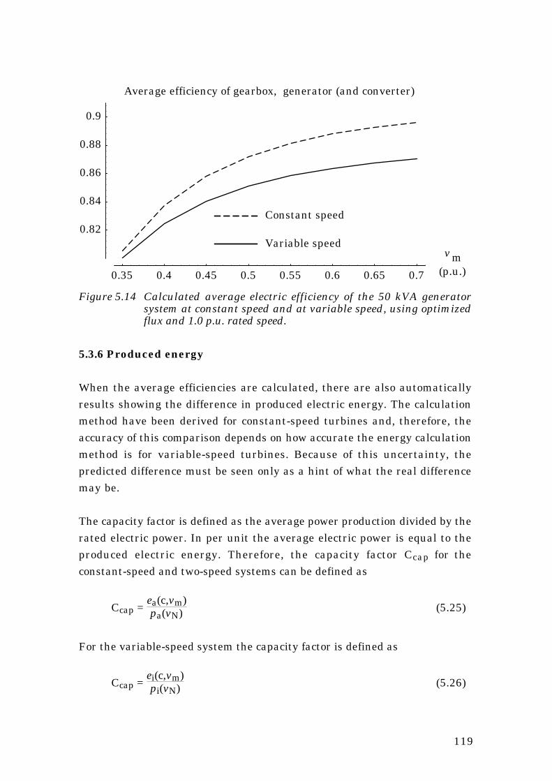
119
0.35 0.4 0.45 0.5 0.55 0.6 0.65 0.7
(p.u.)
Average efficiency of gearbox, generator (and converter)
0.82
0.84
0.86
0.88
0.9
Variable speed
Constant speed
v m
Figure 5.14 Calculated average electric efficiency of the 50 kVA generatorsystem at constant speed and at variable speed, using optimizedflux and 1.0 p.u. rated speed.
5.3.6 Produced energy
When the average efficiencies are calculated, there are also automaticallyresults showing the difference in produced electric energy. The calculationmethod have been derived for constant-speed turbines and, therefore, theaccuracy of this comparison depends on how accurate the energy calculationmethod is for variable-speed turbines. Because of this uncertainty, thepredicted difference must be seen only as a hint of what the real differencemay be.
The capacity factor is defined as the average power production divided by therated electric power. In per unit the average electric power is equal to theproduced electric energy. Therefore, the capacity factor Ccap for theconstant-speed and two-speed systems can be defined as
Ccap = ea(c,vm)pa(vN) (5.25)
For the variable-speed system the capacity factor is defined as
Ccap = ei(c,vm)pi(vN) (5.26)

120
The capacity factor of the turbine can be calculated for different controlstrategies. The comparison is made for a constant-speed , a two-speed and avariable-speed wind turbine generator system using optimized flux and arated generator speed of 1 p.u. The results are shown in figure 5.15.
0.35 0.4 0.45 0.5 0.55 0.6 0.65 0.7
(p.u.)
Capacity factor
0.05
0.1
0.15
0.2
0.25
0.3
0.35
0.4
Variable speed
Two speeds
Constant speedmv
Figure 5.15 The capacity factor of a wind turbine generator system atconstant-speed, two-speed and variable-speed operation.
It can be seen that the capacity factor of the variable-speed system is higherthan that of the constant-speed system. The two-speed system also has ahigh capacity factor compared with the constant-speed system. The figureshows the absolute energy capture, expressed as the capacity factor fordifferent systems. It is, however, difficult to find the relative increase in theenergy production when a constant-speed system is changed to an equal two-speed or variable-speed system from Figure 5.15. The relative increase inproduction is shown in Figure 5.16. The increase in energy production hasbeen calculated for the variable-speed system as
eiVSopt(c,vm)eaCS(c,vm) (5.27)
and for the two-speed system
eaTS(c,vm)eaCS(c,vm) (5.28)

121
0.35 0.4 0.45 0.5 0.55 0.6 0.65 0.7
(p.u.)
Power production compared with a constant-speed system
1
1.05
1.1
1.15
1.2
1.25
Variable-speed system
Two-speed system
mv
Figure 5.16 The relative increase in produced electric energy if a two-speed orvariable-speed system is used instead of a constant-speed system.
It can be seen that the two-speed system produces more than the constant-speed system. The difference between two-speed and variable-speed systemis not so large as the difference between constant-speed and two-speedsystems. For a normal median wind speed the increase in energy productionis about 5.2 % if a variable-speed system is used instead of a constant-speedsystem. If a two-speed system is used the increase is 3.8 %. This comparisonis made for systems with equal rated turbine power and unequal rated outputpower.
5.4 Summary of average efficiency comparison
Although a variable-speed system has extra losses in the generator andconverter it can usually be about as efficient as a constant-speed generator.At low wind speed sites it is more efficient, at high wind speed sites it is lessefficient. The extra losses in the frequency converter have often been said tobe a disadvantage of the variable-speed system. However, the calculations inthis chapter show that the decrease in generator and gear losses cancompensate for the increase in losses due to the frequency converter.
The calculations are based on the use of an efficient frequency converter,with a rated efficiency of 98 %. If a transistorized inverter is used, in order toreduce the network disturbance, the total efficiency will decrease a few

122
percents. Still, the difference in average efficiency between variable-speedand constant-speed systems will be small at medium wind speed sites.

123
6. Conclusions
A model of the losses in the generator and converter has been derived andverified for a 50 kVA generator. The model can be used to predict the shafttorque of the generator with an error of less than 2 % of the rated torque. Thisshould be sufficient for the steady-state torque control of a wind turbine. Themodel only needs measurements of the generator speed, the dc voltage andthe dc current of the converter. Most of the model parameters are, for normalgenerators, available from the manufacturer. The rest of the parameters canbe estimated if the demand on the accuracy is not higher than about 2 %,otherwise they have to be measured.
The loss model can be used to maximize the generator and converterefficiency. By changing the generator voltage, the efficiency of the systemcan be maximized. If the voltage is controlled to maximize the efficiency, thegenerator and converter system is about 0.5 to 0.8 % more efficient, inaverage, than if the common constant flux control is used. It has also beenfound that a variable-speed generator should use a high speed to increase theefficiency and decrease the generator size. To use a larger standard generatorthan necessary does not normally improve the efficiency.
Earlier, it has often been said that the losses in the frequency converter of avariable-speed system are a drawback. In this report it is, however, shownthat the total energy losses do not have to increase because of the frequencyconverter. The generator and gear losses can be reduced when the converteris used, and this reduction may be large enough to compensate for the lossesin an efficient converter. This means that the annual average efficiency of avariable-speed generator system can be as high as that of a constant-speedsystem, at least for turbine sites of normal wind speed. At high wind speedsites the average efficiency is lower and at low wind speed sites it is higher inthe variable-speed system than in the constant-speed system.
The loss model has errors in modelling the additional losses and the corelosses. If the accuracy is critical, the additional losses and the core lossesshould be investigated more thoroughly.
124
7. References
1 Ernst, J., Drezahlvariable Windenergieanlage mit Gleichstrom-zwischenkreis-Umrichter und optimum-suchendem Regler, Germany,Technische Universität Carolo-Wilhelmina zu Braunschweig,Dissertation, 1986, 169 p.
2 Hoeijmakers, M.J., On the steady-state performance of a synchronousmachine with converter, The Netherlands, Technical University ofEindhoven. Dissertation, 1984, 204 p.
3 Hoeijmakers, M. J., Synchronous machine with rectifier for windturbines, IEA 21th meeting of experts – Electrical systems for windturbines with constant and variable speed, Göteborg, Sweden, October7-8, Project Management for Biology, Energy, Ecology (BEO) ResearchCentre Jülich (KFA), 1991, p. 51-61.
4 Carlson, O., Analys av synkrongenerator med frekvensomriktare förelgeneraring vid variabelt varvtal, Göteborg, Sweden, ChalmersUniversity of Technology, Dept. of Electrical Machines and PowerElectronics, Dissertation, Technical Report No. 185, 1988.
5 Svensson, J., Grauers, A., Carlson, O., Förstudie av elsystem tillvindkraftverk med variabelt varvtal, Göteborg, Sweden, ChalmersUniversity of Technology, Dept. of Electrical Machines and PowerElectronics, Technical Report No. R-93-07, 1993, 58 p.
6 Ekström, Å., High power electronics, HVDC and SVC, Stockholm,Sweden, EKC – Electric Power Research Center, The Royal institute ofTechnology, 1990.
7 Hoeijmakers, M.J., The (In)stability of a synchronous machine withdiode rectifier, Internatinal Conference on Electrical Machines(ICEM'92), Manchester, Great Britain, 15 - 17 September 1992,Proceedings, p. 83–87.
8 Jain, G.C., Design, Operation and Testing of Synchronous Machines,New York, USA, Asia, 1966, 676 p.

125
9 El-Bakry, M., Wahsh, S., Upper and lower limits in eddy current andhysteris losses, Internatinal Conference on Electrical Machines(ICEM'92), Manchester, Great Britain, 15 - 17 September 1992,Proceedings, p. 1211–1215.
10 Adkins, B., Harley, R.G., The general theory of alternating currentmachines, London, Great Britain, Chapman and Hall, 1975, 279 p.
11 Shipley, E.E., Loaded gears in action, In: Dudley, D.W. ed., Dudley'sGear Handbook, 2nd edition, New York, Townsend, 1991, p. 12.1 to12.39 .
12 Generator data for the LSA 47 series synchronous generators, France,Leroy Somer ®, 1992, 6 p.
13 IEC Standard 34-1, Rotating electrical machines, Part 1: Rating andperformance, 8th edition, 1983.
14 Ekelund, T., Schmidtbauer, B., Linear quadratic control of variablespeed wind turbines below rated power, Göteborg, Sweden, ChalmersUniversity of Technology, Control Engineering Laboratory, Report No.R 92-04, 1992, 36 p.
Related Documents