PROJECT REPORT DESIGN & FABRICATION OF AN AMPHIBIOUS VEHICLE Project member:- PC-Bilal Majeed (04-BE-ME-96) NS-Bilal Iftikhar (04-BE-ME-106) Project DS:- Sir Raja Amir Azeem 1

Welcome message from author
This document is posted to help you gain knowledge. Please leave a comment to let me know what you think about it! Share it to your friends and learn new things together.
Transcript

PROJECT REPORT
DESIGN & FABRICATION OF AN AMPHIBIOUS VEHICLE
Project member:-PC-Bilal Majeed (04-BE-ME-96)NS-Bilal Iftikhar (04-BE-ME-106)
Project DS:- Sir Raja Amir Azeem
1
PREFACE
The report focuses on the design and fabrication of an amphibious vehicle that although isn’t optimized to the production stage but is a definitive step towards the development and realization of a novel class of advance projects. The report focuses conclusively on the various facets of the projects. The skidding and controlled movement of vehicles is discussed in conjunction with the mechanics in action. Various tire models are discussed, these models include those that are used for the analysis of the model by softwares and those employed for theoretical foundations and manual calculations. Since the vehicle has a versatile compatibility therefore the wide array of situations are discussed in light of the surroundings at hand. Liquid compatibility is considered in light of the lift and drag forces with respect to effective areas. The centroids are considered with dimensions as viewed externally. The maximum angle of inclination retainable in light of friction coefficient is also considered.
The electronics of the project are discussed in a rather superficial manner rather than in detail. The reason being that the electronics was only slightly modified from already present commercial hardware. The slips and forces acting on the tires in basic situations are described by the plots acquired from the ADAMS software.
2

ACKNOWLEDGEMENTS.................................................................................................4CHAPTER 1.........................................................................................................................5INRTODUCTION................................................................................................................5CHAPTER 1: INTRODUCTION.........................................................................................61.1. INITIAL PROSPECTS................................................................................................61.2. BASIC OVERLOOK OF DESIGN:-.............................................................................6
3

ACKNOWLEDGEMENTS
Like all statements that come first define the most imperative of things, we thank our Lord and Master Allah the most merciful and omnipotent. We thank Allah Almighty in this hour of complacence in the wake of completing our project from every angle we thought possible and considered in our ability. Knowing that none of this would have been possible had it not been for HIS endless kindness, had it not been for HIS divine intervention when all seemed lost, had it not been for HIS merciful hand guiding us through when we thought to have reached a dead end. HIS kindness kept us going on in the course of completing this project while all hurdles that came our way were gradually removed. We thank our project DS Sir Raja Amir Azeem who stood by us in the wake of odds we ourselves stated insurmountable, his technical knowledge and guidance have been both an inspiration and an imperative bedrock for this project’s development. We take this moment to thank Mr. Shafique Rekhi without whose guidance and help this project would not have been possible in its present state. We acknowledge the helping hand lent to us by the people of workshop 503 who fabricated the fiber glass top on such short notice and did an immaculate job on the project finish.
We thank our friends who have been with us through thick and thin and who have exhibited the utmost quality of camaraderie and sincerity. They have helped us whenever we sought it from them.
And like all things that come at last, of sublime trait and definitive in quality we commend the role of our parents in the course of our project instantaneously and in our lives on the whole. It was their prayers that have kept us going. Their role in our lives has truly been motivational and inspirational. The way they made everything in their power available has been the backbone of our confidence. Their love has helped us through when we have been put to the test before and this point in our life testifies to it yet again.
4
CHAPTER 1INRTODUCTION
5

CHAPTER 1: INTRODUCTION
1.1. INITIAL PROSPECTS
The initial prospects of the project were primarily focused on the design and fabrication of an all terrain vehicle that could float in water aswell. In order to achieve this more stressed had been laid on the suspension of the vehicle and its compatibility with different types of terrains. The chassis was to be designed in a fashion accommodating 4 wheels with a spring suspension system that could tackle all types of terrains. But in this the amphibious aspect of the vehicle had been overshadowed. It was not until later during the course of time that our project had been designated the design and fabrication task of an amphibious vehicle.
1.2. BASIC OVERLOOK OF DESIGN:-
The basic design of the amphibious vehicle is such that it has 6 wheels. The wheels are all driven by a pair of motors. The 6 wheels are separated in a couple of tire treads and each side has its own driving motor. The tires are driven by a chain and sprocket mechanism. The motor is infact giving the drive to the sprocket which in turn is connected to the 3 gears of the shafts that are connected to the 3 wheels. The same mechanism is for the other set of wheels that are driven by the same mechanism. The vehicle therefore is infact a 6 wheel drive vehicle. The steering system is in itself the outcome of the principle of the skid steering system. The skid steering system has a pair of track treads on each side of the vehicle body and therefore in order to move the vehicle in the straight direction the two motors are made to run in a same speed. It is when the need for turning arises that we see the principle in action. The turning is achieved by the stopping of one set of treads and the speeding up of the other set of treads. Therefore the tread that had sped up acquire a contour whose center or pivot point lies at the center of the tread set that has been made to stop. The tread that has stopped therefore skids thus turning the vehicle in the side of the stopped tread set. Turning can be acquired by partial skidding of the wheels aswell. By slowing one tread or in other words by giving a constant velocity to one set and accelerating the other set we see that the turning is achieved but at a very slow rate and a large arc of
6
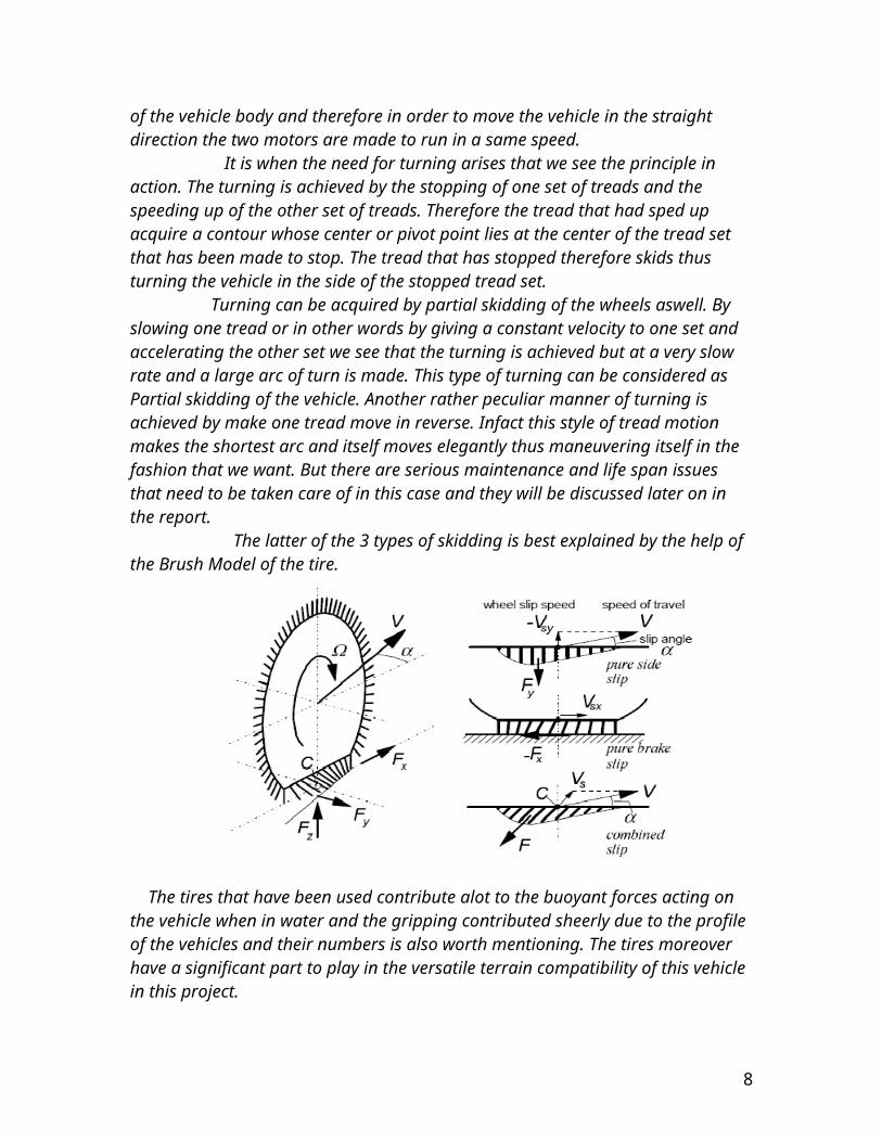
turn is made. This type of turning can be considered as Partial skidding of the vehicle. Another rather peculiar manner of turning is achieved by make one tread move in reverse. Infact this style of tread motion makes the shortest arc and itself moves elegantly thus maneuvering itself in the fashion that we want. But there are serious maintenance and life span issues that need to be taken care of in this case and they will be discussed later on in the report. The latter of the 3 types of skidding is best explained by the help of the Brush Model of the tire.
The tires that have been used contribute alot to the buoyant forces acting on the vehicle when in water and the gripping contributed sheerly due to the profile of the vehicles and their numbers is also worth mentioning. The tires moreover have a significant part to play in the versatile terrain compatibility of this vehicle in this project. Although the details of the tires shall be discussed later on, however it is felt imperative to touch the subject in whatever possible length at this stage. They are 6 in number and have a 10in. diameter. They are 3in. thick and their rim is made out of light plastic. The tires themselves are mounted on a body with the help of shafts. The shafts are made of mild steel and they themselves are connected to the entire driving mechanism with the help of the gear at their other end. The shafts however while being connected to the body have water proof seals at the inside of the body. The body of the vehicle and the shafts and seals are made up of the same material i.e. mild steel. The vehicle itself therefore is primarily made up of mild steel. Surprisingly however at this point that most intellects will concur with using aluminum instead of mild steel. This choice of using this material shall however be discussed later on. The points and reasons of using this material shall adequately advocate our choice. The vehicle itself doesn’t have a suspension for just like many off road vehicles that acquire their suspension via their wheels, same is the case here. The shafts are made of a diameter that makes them capable of transmitting a large amount of force and torque and at the same time allow them to circumvent the shearing that most shaft tend to undergo through by the application of a great magnitude
7
of torque at the driving end and a great but oppositely directed torque produced by the friction and traction of so many wheels at the motion end. The seals that have been used have been employed for the purpose of water proofing the vehicle during the liquid propulsion part of the vehicle terrain compatibility. The seals have been machined from mild steel billets in order to provide them with sufficient material that is imperative to it for providing strength in conjunction with a reasonable amount of weight. From the seals onwards the shafts protrude inward to a gear that is itself connected with whole driving mechanism thus providing motion to the wheels. The gear is connected to the rest of the driving mechanism with the help of a chain. The chain is providing drive to its concerning 3 wheels. The chain is driven by a motor that is itself powered by a 12 volts car battery. The motor is a dc motor commonly employed in vehicles for the motion of the wipers of the front screen.
1.3. DETAILED STUDY OF THE VEHICLE:-
For the detailed study of the vehicle a detailed study of its tires is imperative. The tires being a critical part of its motion in water must be looked into in detail. Since our vehicle has been such that the maneuvering is done primarily by skidding therefore it is a must to know what forces govern this action of skidding. The skidding of tires basically deals with the traction forces between the surface and the tires. We know that when a vehicle is in motion on the road it has traction forces acting on the tires during that motion. The traction forces are also pre,sent in off road conditions rather they are present in a greater magnitude in the off road conditions. There are two conditions which the vehicle may experience during turning and they are:-
CONTROLLED TURNINGSKIDDING
But for these two types of phenomena the forces at work are the same, the available traction designated as TA and the traction demanded, designated as TD . The latter of the two types presented is achieved only when the demanded traction is more than the available traction. However a controlled turning is acquired when the available traction is more or equal to the demanded traction. However from a closer we come to know that the demanded traction is a function of speed, radius of curvature of maneuver, traffic density, degree of vehicle understeer and alertness and skill of the driver. Having this said and taken into consideration we make note that the available traction is approximated as function of speed, combined micro and macro texture of the surface, water depth and other tire traction performance constants such as tread compound, pattern e.t.c. Therefore we can mathematically write the two types of tractions as:-
TD=f(V,Rc^-1,TrD,VU^-1,AS^-1)
8
Where V=velocityRc=radius of curvature of maneuver TrD=traffic densityVU= degree of vehicle understeerAS=alertness and skill of the driver
Similarly the expression for the available traction would become:-
TA=f(V^-1,Tx,Dw^-1,Pt)
Where Tx=combined macro-micro texture of the surfaceDw=water depthPt=certain tire wet traction performances
Therefore from the above expression we can establish that traction demand will be high for high speeds, for low radius or abrupt maneuvers, for high traffic density, for vehicles with low understeer or actual oversteer tendencies and for lack of driver alertness to impending control inputs. Similarly exclusive of the tire properties available traction will be high for low speeds, for high texture pavements, and for low water depths on the pavements. Therefore their ratio will be
Figure 1: Controlled and skid turning
9
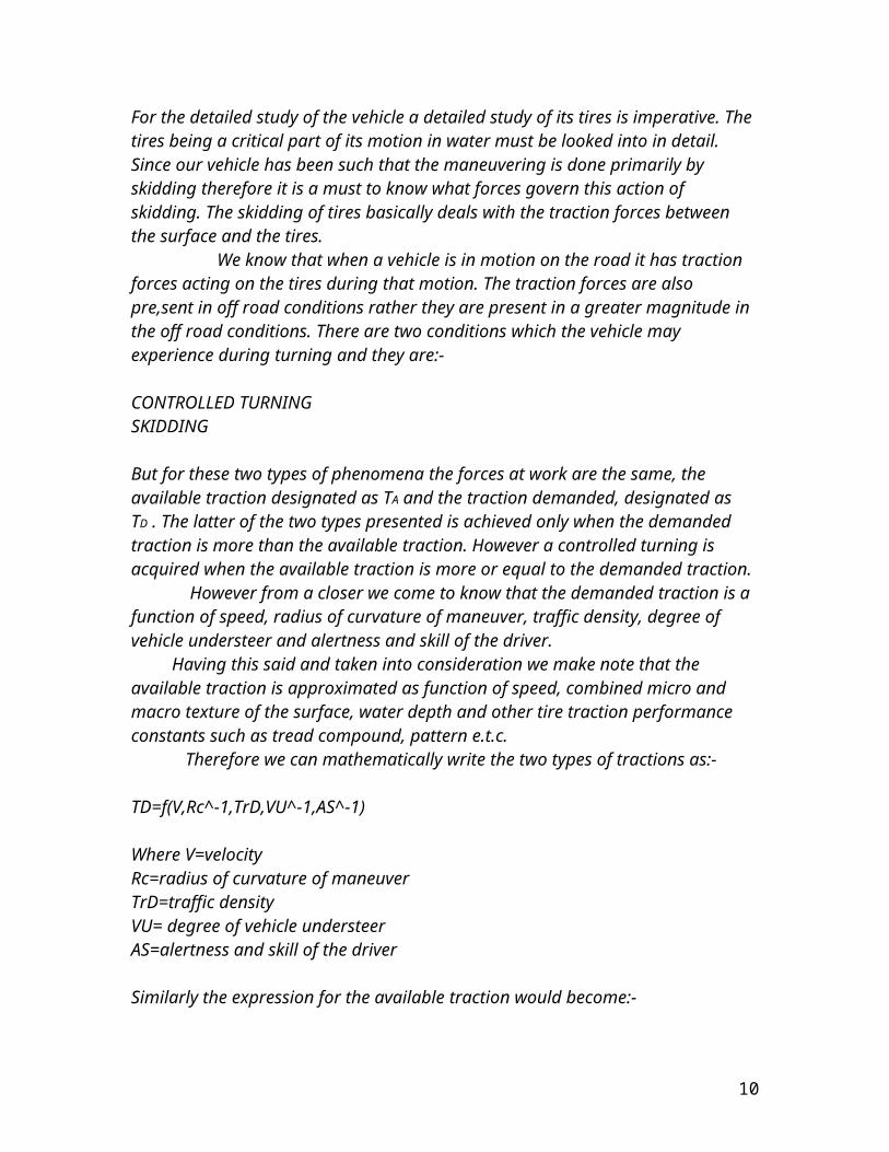
TA=f(V^-1,Tx,Dw^-1,Pt) TD=f(V,Rc^-1,TrD,VU^-1,AS^-1)It is this ratio from which we calculate whether the vehicle will undergo a skid process or will remain under control of the driver at hand.
The control and skidding of a vehicle in motion is governed by the following main factors:- Traction being denoted by μVELOCITYWATER DEPTHSURFACE TEXTURE
We shall discuss each of them one by one. The foregoing analysis illustrated that certain peak values for test speed, water depth and the surface or pavement texture are needed for evaluation. It is necessary to briefly discuss these three factors with regards to tire wet traction level. With this as background certain critical values may be logically selected.
1.4. VELOCITY:- Wet peak and slide braking traction coefficients are reduced by increased speed in an approximately linear manner.
Figure 2: Variation in traction w.r.t speed
10
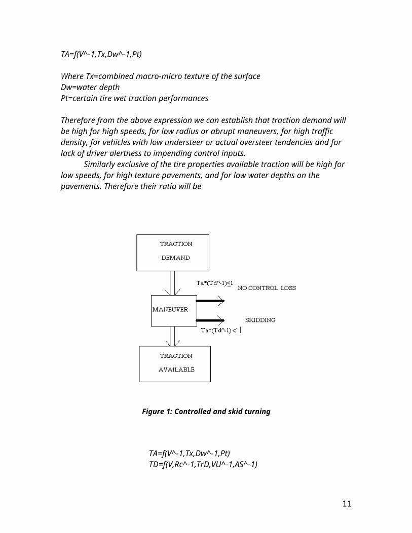
For a vehicle colliding with another vehicle or with a stationary object , the kinetic energy dissipation increases as the square of the impact speed .The required cornering force to round a corner of fixed radius or the distance needed to bring a vehicle to a stop vary as the square of the vehicle speed or velocity. The very strong influence of speed from both viewpoints dictates that high speeds be used for tire evaluation .Experience has shown that a testing speed of 96km/h (60mph) is a reasonable compromise. Higher speed, although desirable in theory ,often cause safety problem in testing and lower speeds (40 to 45 mph) are not sufficiently sensitive to certain water lubrication phenomena to be discussed.
1.5. WATER DEPTH:-
Two aspects must be considered:
The influence of water depth on the traction level.
The average water depths due to rainfall likely to be encountered on roads.
The effect of water depth on traction has been studied by Gegenback and Sabey among many others . All four investigator indicate that traction level is essentially independent of water depth at low speeds, 30 to 50 kph or in other terms 20 to 30 mph. However traction is strongly influenced by depth at high speeds 96 kph or 60 mph. Pelloli found that the slide traction coefficient varied as the log of water depth . It has also been found that a similar cornering traction coefficient versus log water depth relationship exists. The effect of water depth on cornering traction coefficient at 96 kph or 60 mph is 20 times the magnitude at 32 kph or 20mph. It is well established that the on road water depths that are encountered have been caused due to rainfall. Water depth can range for 0.6mm or 0.014in. for a drizzle to 2.4mm or 0.060 in. for a thunder shower. Many data values from many different scientists and experts on this topic have presented values that concur with these set of values.
1.6. SURFACE OR PAVEMENT TEXTURE:-
One of the key surface or pavement factors emphasized at scientific conventions is the “black spot” concept. A black spot is a section of highway that has lost or never had skid resistance and that is located where traction demand is nominally high. This combination causes a high proportion of wet skidding accidents at these black spots. Numerous sources document the fact that the probability of loss of traction is highest on certain sections of public highways .Many others have concurred with the fact that there are certain sections of public highways that are slippery.
11
Based on the ASTM test for Skid resistance of paved surfaces using a full scale tire is used with a standard skid number to rate the highways, roads and fareways based on the follwing criteria.
34minus=dangerous 35 to 43=caution 44 plus=goodIt has been established that the incidence of wet traction accidents increases on low-skid-resistance sections of highways. A survey of the pavement skid resistance showed that accident rates increased significantly at pavement sites with low skid resistance . Approximately 29 percent of the pavements measured in a country wide survey were below his accepted skid number (SN) of 32. This however means that significant amount of care is needed in the designing of tires that can cater to such low skid numbers. It is light of these discussions that one can lay emphasis on the fact that once more when the skid number is low there arises a need for the use, design and employment of such tires that can allow the driver to keep control of the vehicle and at the same there isn’t and excessive amount of traction. This not states the poor states of safety in the country wide highways and roads but this also puts stress on the fact that a tire should be designed so that it can cater to the texture roughness and control within a feasible range. The traction of a pavement here is not the only point of discussion since our tires that are being employed are to work in both on road and off road conditions and therefore have to be made of such treads that can not only perform on the paved but also on the rough off road. Having that said I still remind that the main objective of the vehicle is not the fabrication and employment of a system of an all terrain vehicle rather it is just a bonus that arises from the main course of action i.e. the design and fabrication of an amphibious vehicle. The tires in this case would therefore have to be made up of atleast sufficiently large treads that can accommodate the motion of the vehicle in water while at the same time not forming tire lug holes which are not only the harbingers of tire sinking but also of the tires getting stuck up in some marshy area or in soft clayey area.
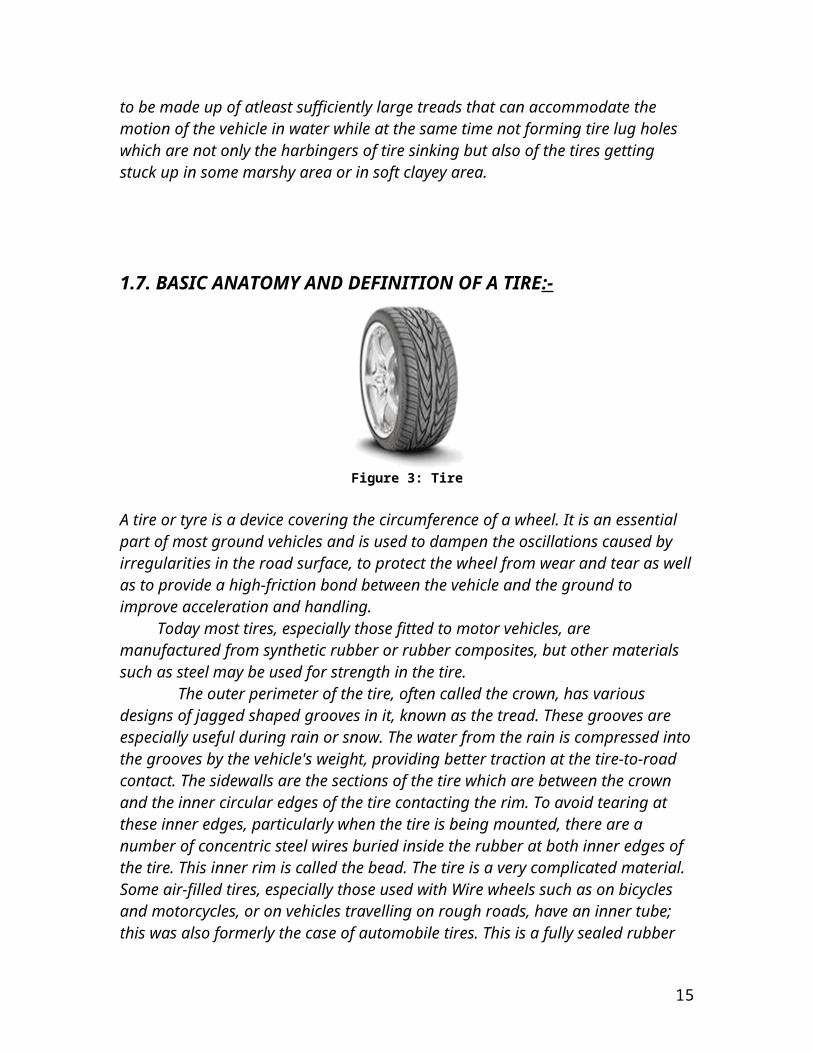
1.7. BASIC ANATOMY AND DEFINITION OF A TIRE:-
Figure 3: Tire
12

A tire or tyre is a device covering the circumference of a wheel. It is an essential part of most ground vehicles and is used to dampen the oscillations caused by irregularities in the road surface, to protect the wheel from wear and tear as well as to provide a high-friction bond between the vehicle and the ground to improve acceleration and handling. Today most tires, especially those fitted to motor vehicles, are manufactured from synthetic rubber or rubber composites, but other materials such as steel may be used for strength in the tire. The outer perimeter of the tire, often called the crown, has various designs of jagged shaped grooves in it, known as the tread. These grooves are especially useful during rain or snow. The water from the rain is compressed into the grooves by the vehicle's weight, providing better traction at the tire-to-road contact. The sidewalls are the sections of the tire which are between the crown and the inner circular edges of the tire contacting the rim. To avoid tearing at these inner edges, particularly when the tire is being mounted, there are a number of concentric steel wires buried inside the rubber at both inner edges of the tire. This inner rim is called the bead. The tire is a very complicated material.Some air-filled tires, especially those used with Wire wheels such as on bicycles and motorcycles, or on vehicles travelling on rough roads, have an inner tube; this was also formerly the case of automobile tires. This is a fully sealed rubber tube with a valve to control flow of air in and out. Others, including modern radial tires, use a seal between the metal wheel and the tire to maintain the internal air pressure (tubeless tires). This method, however, tends to fail if the vehicle is used on rough roads as a small bend on the rim (metal wheel) will result in deflation. The inner tubes are usually made of halobutyl rubber, because of its suitable mechanical properties and excellent impermeability for air. Pneumatic tires generally have reinforcing threads in them; based on the orientation of the threads, they are classified as bias-ply/cross ply or radial. Tires with radial yarns (known as radial tires) are standard for almost all modern automobiles, whereas bias-ply tires are the norm for trailers.
1.8. Tire Physics:-
The amount of traction a tire can deliver depends on a large number of factors:The construction of the tire affects its effective traction - stiff-walled tires (such as run flat tires) behave differently from those with more flexible side-walls. The type of surface that the tire is on (wet or dry road, concrete, asphalt, dirt, sand, etc). The coefficient of friction for normal road tires varies between about 0.7 and 0.4 on dry and wet pavement, respectively. The kind of rubber it is made from - the composition of the tread compounds. Soft rubber molds to the shape of small undulations in the road better than harder compounds and therefore grips better. However, soft rubber also wears out more rapidly than hard rubber so there is a difficult compromise to be made in designing the ideal rubber for a particular application. How hot the rubber is affects how 'sticky' it is? This is why the pit crews in a Formula 1 race team will keep spare tires in special heated blankets in readiness for a pit stop. Race
13
drivers will sometimes deliberately slide their cars from side to side to try to heat up the tires prior to the start of a race. The tread pattern of the tire can also make a big difference. In terms of grip, a bald tire (or a deliberately smooth racing 'slick') has good grip on dry pavement, while the same tire on the same pavement but in wet conditions has poor grip. On the other hand, in wet conditions, a patterned tire allows water to be squeezed out from under the part of the tread that's in contact with the road into the grooves between the treads. This allows more of the rubber to be in contact with the road providing more grip. But in dry conditions its traction is not as good as a smooth tire because the grooves on its surface decrease the tire's contact area. Different tread patterns offer different compromises between wet and dry handling. Specialised treads for winter conditions - or off-road driving further complicate matters. The weight of the vehicle also contributes to the amount of friction created - this is why one sees Drift Cars stripped to the bare minimum, so that there is less friction and the initiation of the drift is relatively easy. When braking, accelerating or cornering, the weight of the vehicle shifts from one set of wheels to another so that some tires may lose traction while others are still gripping the road adequately. Suspension alignment angles also affect a tire's traction. The tire gains most traction when its tread surface is flat on the road. Preloading a tire through adjustment of camber and toe angles is used to great effect in establishing and adjusting handling characteristics of a vehicle. Inflation pressures have a further effect. An under-inflated tire presents a larger surface to the road compared to one that is over-inflated. However, side-wall flex is greater in an under-inflated tire - which can be dangerous and also makes fuel consumption far worse. Understanding the precise behavior of tires is a complex matter, the difference between dynamic and static friction of rubber is significant and the degree of flex in the side-walls of the tire plays a significant part in how it will perform in practice. The force required to make a tire lose grip is much greater than that required to keep the tire slipping once it's moving. Hence, if a vehicle is made to turn too tightly or at too great a speed, an initial small slippage can easily turn into a dangerous skid that is not easily controlled. Tire design has an influence on sound levels produced by a moving vehicle, which effects along with aerodynamic produced sound are much greater than engine noise at high speeds (e.g. greater than 45 miles per hour).
Treads and Tire Wear:-
The grooves or treads found in most tires are there to improve contact between the tire and the road in wet conditions. Without such grooves, the water on the surface of the road would be unable to escape out to the sides of the wheel as the tire presses down onto the road. This causes a thin layer of water to remain between the road and the tire, which causes a complete loss of friction with the road surface. This causes hydroplaning, obliterating traction required for braking, cornering and hard acceleration. The grooves in the tread provide an escape path for the water. Some tire manufacturers claim that
14
their tread pattern is designed to actively pump water out from under the tire by the action of the tread flexing. If the road is dry, tire treads actually reduce grip since they reduce the contact area between the rubber and the road. For this reason treadless or 'slick tires' are often used in motor racing when the track is known to be smooth and dry. If it should rain unexpectedly during the race these slick tires can cause a dangerous loss of grip - which is why they are seldom used on conventional road cars. The contact patch of a tire can be increased, in some circumstances, by lowering the tire pressure. Lowering the tire pressure is a technique used for off-road vehicles in sandy, muddy, or snowy areas, and for drag racing. Decreasing the tire pressure causes the tire to sag so more of the tire is in contact with the surface, giving better traction. It also helps the tire grip small obstacles as the tire conforms more to the shape of the obstacle, and is in contact with the object in more places. However, this increases fuel consumption, tire wear, tire temperature, and raises the likelihood of damage to the wheel if a hard object is struck. Tires that are not designed for variable or lower pressure (such as tires for conventional cars) buckle on hard roads due to their stiffer sidewalls, raising the center of the tire off the surface and reducing, rather than increasing, road contact. The buckling also causes the treads to be squeezed together, reducing their effectiveness. Furthermore, the abnormal stress on an under inflated tire, combined with the resulting temperature increase, can cause the tire to explode while driving. Another technique to improve traction is to use a softer rubber in the treads so that they mould themselves to the shape of the road surface, though this wears the tire more quickly than harder tires. Since the rubber is softer when warm, race pit crews may even keep tires in warmers to keep new tires at the optimum temperature until they are to be driven on. Soft compound rubber would also improve traction in street vehicles, but it is seldom used because these tires wear out too quickly for normal use.The depth of the tread grooves is an important part of car safety but that depth gradually reduces due to wear throughout the lifetime of a tire. When the tread on the outer perimeter of the tire wears away, reducing the tread depth, the tire should be replaced. Many countries have laws regulating the minimum tread depth on road vehicles and most modern road tires have built-in tread wear indicators. These take the form of small blocks of rubber moulded into the bottoms of the grooves of the tread at intervals around the tire. When the tread has worn down until the tops of those blocks are level with the top of the tread - then the tire needs to be replaced. If these blocks are not present, a tire tread depth gauge should be used to measure the depth. In most vehicles, either the front or rear tires will wear faster than the others. Having mismatched tread depths can alter the handling of the car in unacceptable ways - so it is generally advisable to swap the front and rear tires as they wear down to even out the wear patterns. This is called rotating the tires. If the vehicle's suspension is somewhat out of adjustment, it is also possible for the tires to wear more on one side than the other - so it may also be beneficial to rotate the tires from one side of the car to the other - however, careful attention should be paid to the owner's manual since some vehicles require particular tire rotation patterns.
15

Notably, some tires are designed to provide best traction only when spinning in a clockwise or counter-clockwise direction. In such cases one must not rotate the tires from one side of the car to the other because that would put a 'clockwise tire' onto a wheel that turns in a counter-clockwise direction (and vice versa). Such tires typically have an arrow moulded into the sidewall to indicate the preferred direction.
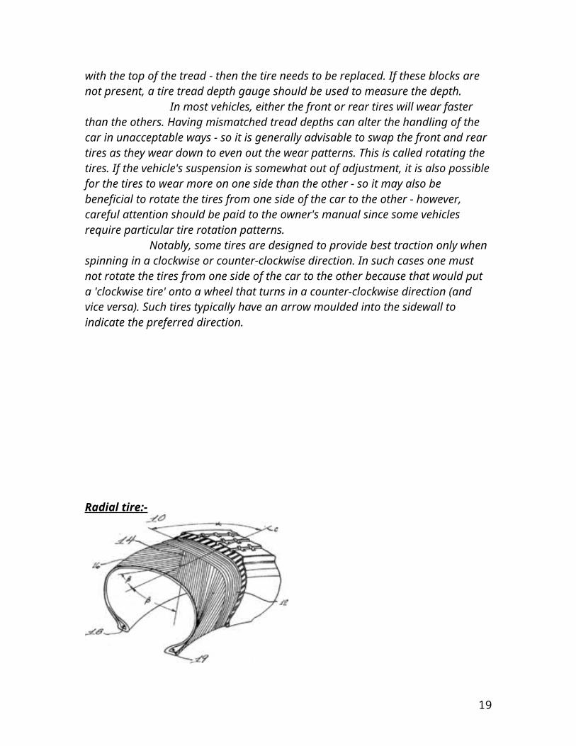
Radial tire:-
A cross-section of a tire (tyre). Number 12 indicates the radial-ply. Numbers 14 and 16 are bias-plies. A radial tire (more properly, a radial-ply tire) is a particular design of automotive tire (in British English, tyre). The design was originally developed by Michelin in 1946 but, because of its advantages, has now become the standard design for essentially all automotive tires. Tires are not fabricated just from rubber; they would be far too flexible and weak. Within the rubber are a series of plies of cord that act as reinforcement. All common tires (since at least the 1960s) are made of layers of rubber and cords of polyester, steel, and/or other textile materials. This network of cords that gives the tire strength and shape is called the carcass. In the past, the fabric was built up on a flat steel drum, with the cords at an angle of about +60 and -60 degrees from the direction of travel, so they criss-crossed over each other. They were called cross ply or bias ply tires. The plies were turned up around the steel wire beads and the combined tread/sidewall applied. The green (uncured) tire was loaded over a curing bladder and shaped into the mould. This shaping process caused the cords in the tire to assume an S shape from bead to bead. The
16

angle under the tread stretched down to about 36 degrees. This was called the Crown Angle. In the sidewall region the angle was 45 degrees and in the bead it remained at 60 degrees. The low crown angle gave rigidity to support the tread and the high sidewall angle gave comfort. By comparison, radial tires lay all of the cord plies at 90 degrees to the direction of travel (that is, across the tire from lip to lip). This design avoids having the plies rub against each other as the tire flexes, reducing the rolling friction of the tire. This allows vehicles with radial tires to achieve better fuel economy than vehicles with bias-ply tires. It also accounts for the slightly "low on air" (bulging) look that radial tire sidewalls have, especially when compared to bias-ply tires. Construction:-
As described, a radial tire would not be sufficiently strong and the surface in contact with the ground would not be sufficiently rigid. To add further strength, the entire tire is surrounded by additional belts that are oriented along the direction of travel. First made of tire cord, these belts were made of steel (hence the term "steel-belted radial") by 1948 and subsequently Polyester or later Aramid fibers such as Twaron and Kevlar.In this way, radial tires separate the tire carcass into two separate systems:
The radial cords in the sidewall allow it to act like a spring, giving flexibilty and ride comfort.
The rigid steel belts reinforce the tread region, giving high mileage and performance.
Each system can then be individually optimized for best performance.
Tire types:-Wagon tires:-The earliest tires were hoops of metal placed around wagon wheels. The tire was heated in a forge, placed on the wheel and quenched, causing the metal to shrink, which drew the rim against the spokes and provided stiffness to the wheel. This work was done by a wheelwright, a craftsman who specialized in making wagon wheels.Pneumatic tires:-Air-filled tires are known as pneumatic tires, and these are the type in almost universal use today. Pneumatic tires are made of a flexible elastomer material such as rubber with reinforcing threads/wires inside the elastomer material. The air compresses as the wheel goes over a bump and acts as a shock absorber. Tires are inflated through a valve, typically a Schrader valve on automobiles and most bicycle tires, or a Presta valve on high performance bicycles. Various types of solid tire have met with little success since the safety bicycle became widespread a hundred years ago. The air in conventional pneumatic tires acts as a near constant rate spring because the decrease in the tire's volume as the tire compresses over a bump is minimal. "Airless" tires usually employ a type of foam or sponge like construction which consists of a large number of small air filled cells. As a result, compression is localised
17

within the tire and the effective spring rate rises sharply as the tire compresses. The result is a tire which is less forgiving, particularly with regards to sharp transient bumps and provides poor ride and handling characteristics. The "steering feel" of such tires is also different from that of pneumatic tires, as their solidity does not allow the amount of torsion that exists in the carcass of a pneumatic tire under steering forces, and the resultant sensory feedback through the steering apparatus; as a result they feel as if they are pivoting on bearings at the contact point. They are more popular for bicycles than for automobiles, which have tires which are much more robust and immune to puncture. The common motor vehicle tire is mounted around a steel or aluminum alloy wheel at service stations or repair shops for vehicles using a special tire mounting apparatus while the wheel is off the vehicle. After mounting, the tire is inflated (pressurized) with air through the valve stem to manufacturer's specified pressure, which is higher than atmospheric pressure. The wheel and tire assembly are then attached to the vehicle through a number of holes in the wheel using lug nuts. Because tires are often not made with perfectly even mass all around the tire, a special tire-balancing apparatus at a repair shop spins the wheel with the tire to determine where small weights should be attached to the outer edges of the rim to balance out the wheel. Such tire balancing with these kind of weights avoids vibration when the vehicle is driven at higher speeds.Tires are checked at the point of manufacture for excessive static imbalance and dynamic imbalance using automatic Tire Balance Machines With the introduction of radial tires it was found that some vibrations could not be cured by adding balance weights. This was because the structure and manufacture of a radial tire lends itself to the problems of variation in stiffness around the tire. These variations are collectively referred to as Tire Uniformity. Tire Unifomity is characterized by Radial Force Variation (RFV), Lateral Force Variation(LFV), and Tangential Force Variation. Radial and Lateral Force Variation is measured on a Force Variation Machine at the end of the manufacturing process. Tires outside the specified limits for RFV and LFV are rejected. In addition, Tire Unifrmity Machines are used to measure geometric parameters including Radial Runout, Lateral Runout, and Sidewall BulgeAutomobile and truck tires:-Automobile tires have numerous rating systems. New automotive tires now also have ratings for traction, treadwear, and temperature resistance (collectively known as UTQG ratings); as well as speed and load ratings. Some tread designs are unidirectional and the tire has a rotation direction indicated by an arrow showing which way the tire should rotate when the vehicle is moving forwards. It is important not to put a 'clockwise' tire on the left hand side of the car or a 'counter-clockwise' tire on the right side. Tire rotation moves tires between the different wheels of the vehicle as front and back axles carry different loads and thus the tires wear differently. Tire tread gauges are small rulers designed to be inserted into tire treads to measure the remaining tread depth. Local legislation may specify minimum tread depths, typically between 1/8" (3.2 mm) and 1/32" (0.8 mm). Wearbars may be designed
18
into the tire tread to indicate when it is time to replace the tire. Essentially, part of the tire tread is shallower than the rest and will show when the tire is worn down to that level. There is currently an attempt to reinforce the tire with nanomaterial. This is likely to increase the tire life, but may turn out to be a bad idea if the worn out part of nanocarbon deposited on the roads is washed off and ends up in the food chain.Types of automobile tires:-
Performance (and racing) tires .Performance tires tend to be designed for use at higher speeds. They often have a softer rubber compound for improved traction, especially on high speed cornering. The trade off of this softer rubber is a lower treadwear rating. Performance street tires sometimes sacrifice wet weather handling by having shallower water channels to provide more actual rubber tread surface area for dry weather performance. The ability to provide a high level of performance on both wet and dry pavement varies widely between manufacturers and even tire models of the same manufacturer. This is an area of active research and development, as well as marketing. The ultimate variant of performance tire has no tread pattern at all and is called a slick tire. Slick tires are not legal for use on public roads in most jurisdictions due to their extremely poor wet weather characteristics, but cheater slicks, which meet the literal wording of the law, if not the intent, are available. R compound tires, similar to cheater slicks, are considered as street legal, but are in fact designed for racing, with minimal tread and ultrasoft rubber. They can typically be distinguished by very low treadwear rating. The highest performance tires designed to be driven on the street are often called summer or three-season tires, since they are optimized for ultimate warm weather wet and dry performance at the expense of snow and ice traction. They must be replaced with winter or all-season tires if the vehicle is to be driven much in the winter.
Winter (snow and ice) tires:-
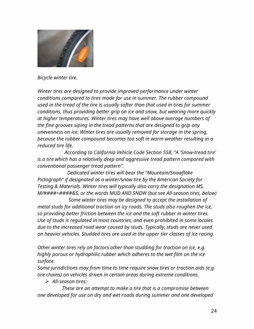
Bicycle winter tire.
Winter tires are designed to provide improved performance under winter conditions compared to tires made for use in summer. The rubber compound used in the tread of the tire is usually softer than that used in tires for summer conditions, thus providing better grip on ice and snow, but wearing more quickly at higher temperatures. Winter tires may have well above average numbers of the fine grooves siping in the tread patterns that are designed to grip any unevenness on ice. Winter tires are usually removed for storage in
19

the spring, because the rubber compound becomes too soft in warm weather resulting in a reduced tire life. According to California Vehicle Code Section 558, "A 'Snow-tread tire' is a tire which has a relatively deep and aggressive tread pattern compared with conventional passenger tread pattern". Dedicated winter tires will bear the "Mountain/Snowflake Pictograph" if designated as a winter/snow tire by the American Society for Testing & Materials. Winter tires will typically also carry the designation MS, M/####+####&S, or the words MUD AND SNOW (but see All-season tires, below) Some winter tires may be designed to accept the installation of metal studs for additional traction on icy roads. The studs also roughen the ice, so providing better friction between the ice and the soft rubber in winter tires. Use of studs is regulated in most countries, and even prohibited in some locales due to the increased road wear caused by studs. Typically, studs are never used on heavier vehicles. Studded tires are used in the upper tier classes of ice racing.
Other winter tires rely on factors other than studding for traction on ice, e.g. highly porous or hydrophilic rubber which adheres to the wet film on the ice surface. Some jurisdictions may from time to time require snow tires or traction aids (e.g. tire chains) on vehicles driven in certain areas during extreme conditions.
All-season tires:- These are an attempt to make a tire that is a compromise between one developed for use on dry and wet roads during summer and one developed for use under winter conditions. The type of rubber and the tread pattern best suited for use under summer conditions cannot, for technical reasons, give good performance on snow and ice. The all-season tire is a compromise, and is neither an excellent summer tire nor an excellent winter tire. They have, however, become almost ubiquitous as original and replacement equipment on automobiles marketed in the United States, due to their convenience and their adequate performance in most situations. All-Season tires are also marked for mud and snow (e.g. M+####&S, etc.) the same as winter tires. Owing to the compromise with performance during summer, winter performance is usually poorer than a winter tire.
Run flat tire All-terrain tire:-
All-terrain tires are typically used on SUVs and light trucks. These tires often have stiffer sidewalls for greater resistance against puncture when traveling off-road, the tread pattern offers wider spacing than all-season tires to remove mud from the tread. Within the all-terrain category, many of the tires available are designed primarily for on-road use, particularly all-terrain tires that are originally sold with the vehicle.
Mud tires:- Mud terrain tires are characterized by large, chunky tread patterns designed to bite into muddy surfaces. The large open design also allows mud to clear quickly from between the lugs.
20
Mud terrain tires also tend to be wider than other tires, to spread the weight of the vehicle over a greater contact patch to prevent the vehicle from sinking too deeply into the mud. Depending on the composition and tread pattern, many mud terrain tires are not well suited to on-road use. They can be noisy at highway speeds, and due to the open tread design they have less contact area with the road which limits traction. The large lugs on mud tires tend to tear and chip on roads since they are made from hard rubber compounds that do not bend easily. Mud tires are also marked for mud and snow (e.g. M+####&S, etc.) the same as winter tires. Sand tires:-Tires for use in soft sand are very wide and run at low pressure. The shallow tread pattern is a series of polygonal blocks with angled shoulders. These are designed to press into the sand and gain support by increasing the friction between the grains. Conventional mud terrain tread patterns which rely on the shear strength of the ground merely cut into the sand and scoop it away, quickly digging the tire in. Sand tires are ineffective in mud, where the low pressure and tread pattern does not bite into the ground. Aviation tires:-Aviation tires on airplanes are designed to withstand heavy loads. On narrow body aircraft, there are usually 6 tires, consisting of 2 wheels for each main landing gear and 2 front tires at the nose landing gear. Heavier aircraft, such as the Antonov An-124 and widebody aircraft such as the Boeing 747 the Airbus A340 and the Boeing 767 have a series of wheels, not a set. With more landing gears and bogies which carry more tires each, they also have tires spaced further apart than narrowbody aircraft. Widebody or heavy aircraft have a series of wheels because landing can impose a dynamic load as much as 100,000 pounds beyond rest weight. The plane needs to distribute the weight evenly and soften the load, making a smoother landing, saving costs on tires, putting less stress on the landing gear and on the runway. Planes with a series of landing gears often have a stop bar in front of the first row of wheels to act as brakes. On a plane with 4 tires per main landing gear they are usually mounted on a rack type boggie, which keeps the landing gear in a diagonal almost vertical, attitude. When the plane touches tarmac, the last(second) row of the main landing gear touches the ground first thus forcing the 1st row of tires down. Multi wheeled landing gears or planes have more wheels to reduce the amount of shock transferred to the fuselage thus making a more comfortable landing. These are filled with nitrogen gas, to remain inert at the various pressures the aircraft will undergo in a flight. Aviation tire treads only have lateral traction strips, since the plane doesn't have power sent through their wheels. The tires have deep sipping because it helps the plane maintain an extremely high amount of grip during crosswind landings. The wide sipping also prevent hydroplaning off the runway. Aviation tires are expensive, costing up to $4,000 a tire (Goodyear on-line price list). Aviation tires generally operate at high pressures, up to 200 psi for airliners and higher for business jets. If aviation tires are not deflated before disassembly serious injury or death can result. Proper inflation is
21

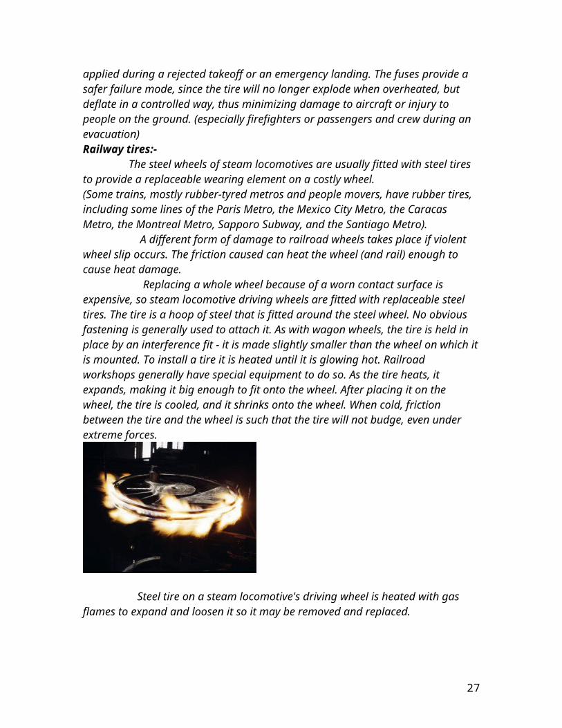
of the utmost importance as under-inflation can result in tire damage, aircraft damage or loss of the aircraft. (see the video "Death of an Airline" Maintenance and Ramp Safety Society, c1998) Aviation tires also include heat fuses, which melt when a certain temperature is reached. Tires often overheat if maximum braking is applied during a rejected takeoff or an emergency landing. The fuses provide a safer failure mode, since the tire will no longer explode when overheated, but deflate in a controlled way, thus minimizing damage to aircraft or injury to people on the ground. (especially firefighters or passengers and crew during an evacuation)Railway tires:- The steel wheels of steam locomotives are usually fitted with steel tires to provide a replaceable wearing element on a costly wheel.(Some trains, mostly rubber-tyred metros and people movers, have rubber tires, including some lines of the Paris Metro, the Mexico City Metro, the Caracas Metro, the Montreal Metro, Sapporo Subway, and the Santiago Metro). A different form of damage to railroad wheels takes place if violent wheel slip occurs. The friction caused can heat the wheel (and rail) enough to cause heat damage. Replacing a whole wheel because of a worn contact surface is expensive, so steam locomotive driving wheels are fitted with replaceable steel tires. The tire is a hoop of steel that is fitted around the steel wheel. No obvious fastening is generally used to attach it. As with wagon wheels, the tire is held in place by an interference fit - it is made slightly smaller than the wheel on which it is mounted. To install a tire it is heated until it is glowing hot. Railroad workshops generally have special equipment to do so. As the tire heats, it expands, making it big enough to fit onto the wheel. After placing it on the wheel, the tire is cooled, and it shrinks onto the wheel. When cold, friction between the tire and the wheel is such that the tire will not budge, even under extreme forces.
Steel tire on a steam locomotive's driving wheel is heated with gas flames to expand and loosen it so it may be removed and replaced.
Removing a tire is done in reverse - the tire is heated while on the wheel until it loosens. Tires are reasonably thick, up to about an inch thick or more, giving plenty of room to wear. If a tire wears out of shape, or gets flat-spotted, but has a reasonable
22

amount of material remaining, it can be turned on a wheel lathe to refinish it, reshaping it to the correct profile.
Tire Uniformity:-
Tire Uniformity refers to the dynamic mechanical properties of pneumatic tires as strictly defined by a set of measurement standards and test conditions accepted by global tire and car makers. These measurement standards include the parameters of radial force variation, lateral force variation, conicity, plysteer, radial runout, lateral runout, and sidewall bulge. Tire makers worldwide employ tire uniformity measurement as a way to identify poorly performing tires so they are not sold to the marketplace. Both tire and vehicle manufacturers seek to improve tire uniformity in order to improve vehicle ride comfort.
Tire uniformity parameters:-
Axes of measurement:-
Tire forces are divided into three axes: radial, lateral, and tangential. The radial axis runs from the tire center toward the tread, and is the vertical axis running from the roadway through the tire center toward the vehicle. This axis supports the vehicle’s weight. The lateral axis runs sideways across the tread. This axis is parallel to the tire mounting axle on the vehicle. The tangential axis is the one in the direction of the tire travel.
Radial force variation:-
Insofar as the radial force is the one acting upward to support the vehicle, radial force variation describes the change in this force as the tire rotates under load. As the tire rotates and spring elements with different spring constants enter and exit the contact area, the force will change. Consider a tire supporting a 1,000 load running on a perfectly smooth roadway. It would be typical for the force to vary up and down from this value. A variation between 995 pounds and 1003 pounds would be characterized as an 8 pound radial force variation, or RFV. RFV can be expressed as a peak-to-peak value, which is the maximum minus minimum value, or any harmonic value as described below.
Harmonic analysis:-
RFV, as well as all other force variation measurements, can be shown as a complex waveform. This waveform can be expressed according to its harmonics by applying Fourier Transform (FT). FT permits one to parameterize various aspects of the
23
tire dynamic behavior. The first harmonic, expressed as RF1H (radial force first harmonic) describes the force variation magnitude that exerts a pulse into the vehicle one time for each rotation. RF2H expresses the magnitude of the radial force that exerts a pulse twice per revolution, and so on. Lateral force variation:-
Insofar as the lateral force is the one acting side-to-side along the tire axle, lateral force variation describes the change in this force as the tire rotates under load. As the tire rotates and spring elements with different spring constants enter and exit the contact area, the lateral force will change. As the tire rotates it may exert a lateral force on the order of 25 pounds, causing steering pull in one direction. It would be typical for the force to vary up and down from this value. A variation between 22 pounds and 26 pounds would be characterized as a 4 pound lateral force variation, or LFV. LFV can be expressed as a peak-to-peak value, which is the maximum minus minimum value, or any harmonic value as described below. Tangential force variation:-
Insofar as the tangential force is the one acting in the direction of travel, tangential force variation describes the change in this force as the tire rotates under load. As the tire rotates and spring elements with different spring constants enter and exit the contact area, the tangential force will change. As the tire rotates it exerts a high traction force to accelerate the vehicle and maintain its speed under constant velocity. Under steady-state conditions it would be typical for the force to vary up and down from this value. This variation would be characterized as TFV.
Conicity:- Conicity is a parameter based on lateral force behavior. It is the characteristic that describes the tire’s tendency to roll like a cone. This tendency affects the steering performance of the vehicle. In order to determine Conicity, lateral force must be measured in both clockwise (LFCW) and counterclockwise direction (LFCCW). Conicity is calculated as one-half the difference of the values, keeping in mind that CW and CCW values have opposite signs. Conicity is an important parameter is production testing.
Plysteer:-
Plysteer is a parameter based on lateral force behavior. In order to determine Plysteer, lateral force must be measured in both clockwise (LFCW) and counterclockwise direction (LFCCW). Plysteer is calculated as one-half the sum of the values, keeping in mind that CW and CCW values have opposite signs. Plysteer is not measured in production testing.
Radial runout:-
24
Radial Runout (RRO) describes the deviation of the tire’s roundness from a perfect circle. RRO can be expressed as the peak-to-peak value as well as harmonic values. RRO imparts an excitation into the vehicle in a manner similar to radial force variation. RRO is most often measured near the tire’s centerline.
Lateral runout:-
Lateral Runout (LRO) describes the deviation of the tire’s sidewall from a perfect plane. LRO can be expressed as the peak-to-peak value as well as harmonic values. LRO imparts an excitation into the vehicle in a manner similar to lateral force variation. LRO is most often measured in the upper sidewall, near the tread shoulder.
Sidewall bulge and depression:-
Given that the tire is an assembly of multiple components that are cured in a mold, there are many process variations that cause cured tires to be classified as rejects. Bulges and depressions in the sidewall are such defects. A bulge is a weak spot in the sidewall that expands when the tire is inflated. A depression is a strong spot that does not expand in equal measure as the surrounding area.
TIRE MODELS USED:-
The tires are of many types and they have been listed and explained in detail in the earlier portions of the report. The tires however that need to be explained also are the tire types that are used in ADAMS and the tire type that is used in the fabrication of the project. The tires that we have used in the fabrication part of the model will be discussed in detail alongwith their dimensions and their tread pattern in details in the latter part of the report, however for now it is imperative to consider the tire models used for the simulation of the model and designing of the project as a whole.
The tires that are used in ADAMS are as follows:- 521 tire model Fiala tire model UA tire model
Pacejka tire model:- Pacejka 89 Pacejka 94 MF tire models.
521 TIRE MODEL:-
It is first incorporated tire in ADAMS 521 refers to 5.2.1 which was the early version.
25
There are two dedicated contact methods for this model:-
POINT FOLLOWER METHOD EQUIVALENT PLANE METHOD
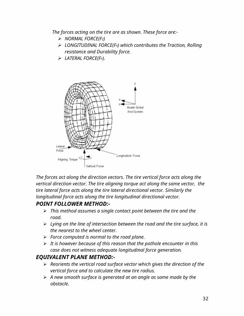
The forces acting on the tire are as shown. These force are:- NORMAL FORCE(FZ) LONGITUDINAL FORCE(FX) which contributes the Traction, Rolling
resistance and Durability force. LATERAL FORCE(FY).
The forces act along the direction vectors. The tire vertical force acts along the vertical direction vector. The tire aligning torque act along the same vector, the tire lateral force acts along the tire lateral directional vector. Similarly the longitudinal force acts along the tire longitudinal directional vector.POINT FOLLOWER METHOD:-
This method assumes a single contact point between the tire and the road. Lying on the line of intersection between the road and the tire surface, it is the
nearest to the wheel center. Force computed is normal to the road plane. It is however because of this reason that the pothole encounter in this case does
not witness adequate longitudinal force generation. EQUIVALENT PLANE METHOD:-
Reorients the vertical road surface vector which gives the direction of the vertical force and to calculate the new tire radius.
26
A new smooth surface is generated at an angle as same made by the obstacle. This methodology holds for an obstacle larger than the contact patch but is
inaccurate for smaller objects like tar strip or gravel.
FIALA TIRE MODEL:-The assumptions of this tire model are:-
Rectangular contact patch or footprint. Pressure distribution is uniform across contact patch. Tire is modeled as a beam on elastic foundation. Camber angle has no effect on tire forces.
The inputs to the FIALA tire model come from two sources:- Input parameters from the tire property file (.tir). Tire kinematic states such as slip angles which ADAMS calculates.
The force evaluations are as follows:- Normal force of road on tire. Longitudinal force. Lateral force. Rolling resistance moment. Aligning moment.
UA-TIRE MODEL:-
The UA is an acronym for the University of Arizona where it was developed. Includes relaxation effects in the longitudinal and lateral direction. It calculates the forces at the ground contact point as a function of the tire
kinematic states. The inputs and outputs of this model are:-
27

PACEJKA TIRE MODEL:-
Further classified into pacejka 89 and pacejka 94. It is compatible to the existing or new ADAMS tire data format. Pacejka 89 conforms to modified and pacejka 94 to the standard SAE tire
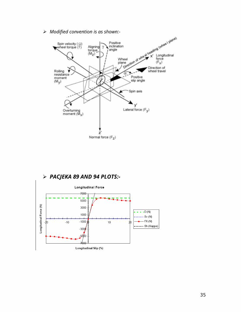
coordinate and sign convention. The modified sign convention and coordinate system is as shown:-
28

Modified convention is as shown:-
PACJEKA 89 AND 94 PLOTS:-
29
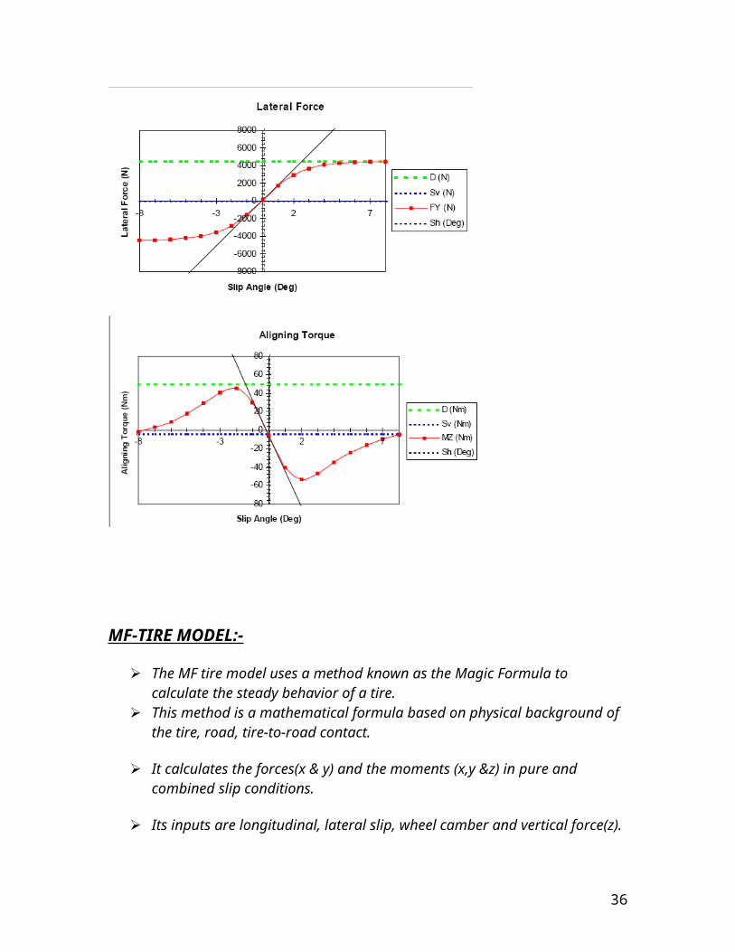
MF-TIRE MODEL:-
The MF tire model uses a method known as the Magic Formula to calculate the steady behavior of a tire.
This method is a mathematical formula based on physical background of the tire, road, tire-to-road contact.
It calculates the forces(x & y) and the moments (x,y &z) in pure and combined slip conditions.
Its inputs are longitudinal, lateral slip, wheel camber and vertical force(z).
It is a rather more used model.
30
It has two version 5.1 and 5.2 .
5.2 changes for its prior version on the following grounds:-
Scaling factors for the shifts have been defined and now features can be switched off.
E factors have been introduced into the modeling of combined, cornering traction for accuracy.
Influence of the camber on the peak Fx has been introduced.
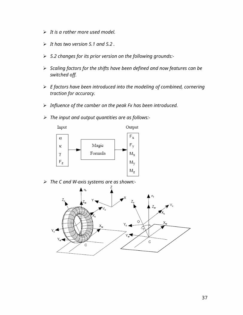
The input and output quantities are as follows:-
The C and W-axis systems are as shown:-
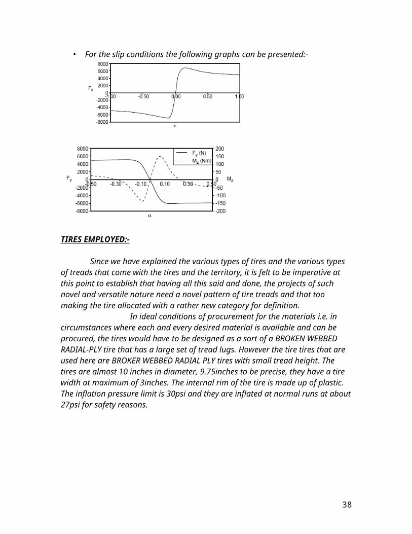
• For the slip conditions the following graphs can be presented:-
31
TIRES EMPLOYED:-
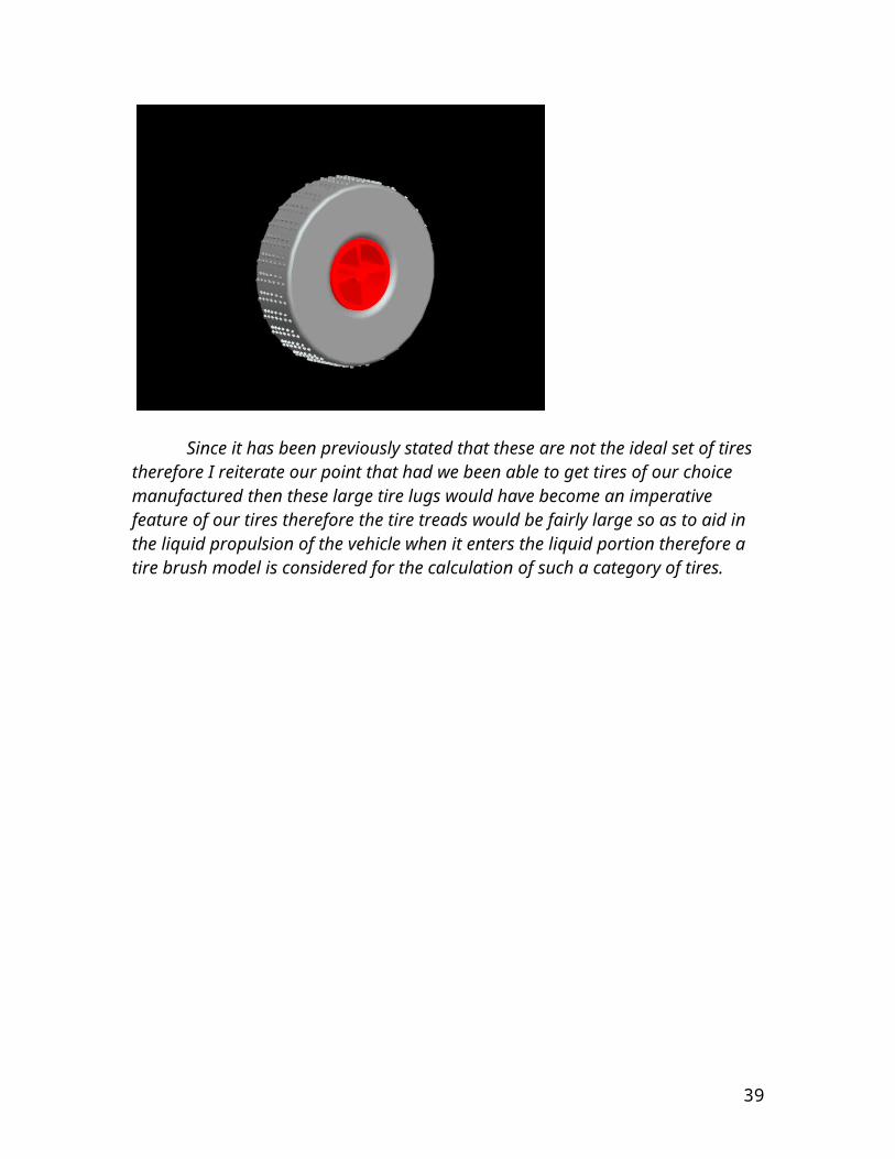
Since we have explained the various types of tires and the various types of treads that come with the tires and the territory, it is felt to be imperative at this point to establish that having all this said and done, the projects of such novel and versatile nature need a novel pattern of tire treads and that too making the tire allocated with a rather new category for definition. In ideal conditions of procurement for the materials i.e. in circumstances where each and every desired material is available and can be procured, the tires would have to be designed as a sort of a BROKEN WEBBED RADIAL-PLY tire that has a large set of tread lugs. However the tire tires that are used here are BROKER WEBBED RADIAL PLY tires with small tread height. The tires are almost 10 inches in diameter, 9.75inches to be precise, they have a tire width at maximum of 3inches. The internal rim of the tire is made up of plastic. The inflation pressure limit is 30psi and they are inflated at normal runs at about 27psi for safety reasons.
Since it has been previously stated that these are not the ideal set of tires therefore I reiterate our point that had we been able to get tires of our choice manufactured then these large tire lugs would have become an imperative feature of our tires therefore the tire treads would be fairly large so as to aid in the liquid propulsion of
32
the vehicle when it enters the liquid portion therefore a tire brush model is considered for the calculation of such a category of tires.
TIRE BRUSH MODEL
The brush model consists of a row of elastic bristles that touches the road surface. These bristles may be called tread elements. Their compliance represents the elasticity of the carcass, belt and actual tread elements of the real tire. As the tire rolls the first element that enters the contact zone is assumed to stand perpendicularly with respect to the road surface. When the tire rolls feely without any side slip and under the action of no force the tire bristles or the treads are assumed to be without any slip or any camber and therefore they move from the leading edge to the trailing edge. However when the wheel speed vector V shows an angle to the plane of the wheel motion then a certain amount of side slip occurs. The steady slip force and moment generation are given in a pictorial form below. In that tire brush model in the top left place there is a view of a driven and side slipping tire. In the top right there is a view of a tire at different slip conditions. In the bottom left part of the diagram there is a view of the pure side slip from small to large slip angles. In the bottom there is a view of the resulting side force and aligning torque characteristics.
33

The tread elements move from the leading edge to trailing edge. The tip of element will be as long as the available friction allows. In the lower part of the figure the model is shown at pure side slip. The slip changes from very small to relatively large. It is observed that the deflections increase as the contact patch increases. The deflection rate is equal to the assumedly constant slip speed. The pure side slip is shown in the top and side view. These views are shown in the following diagram and the forces and the moments are shown for the pure side slip conditions. The type of slip conditions are as given below, they are:-
Pure side slip Pure longitudinal slip Combined slip
34
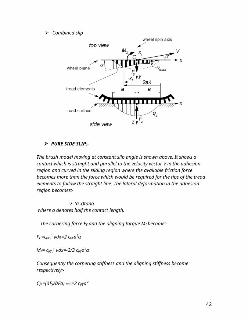
PURE SIDE SLIP:-
The brush model moving at constant slip angle is shown above. It shows a contact which is straight and parallel to the velocity vector V in the adhesion region and curved in the sliding region where the available friction force becomes more than the force which would be required for the tips of the tread elements to follow the straight line. The lateral deformation in the adhesion region becomes:-
ν=(a-x)tanα where a denotes half the contact length. The cornering force Fy and the aligning torque Mz become:-
Fy =cpy∫ νdx=2 cpya²α
Mz= cpy∫ νdx=-2/3 cpya³α
Consequently the cornering stiffness and the aligning stiffness become respectively:-
Cfα=(∂Fy/∂Fα) α=0=2 cpya²
CMα=-(∂MZ/∂M α) α=0=2/3 cpya³
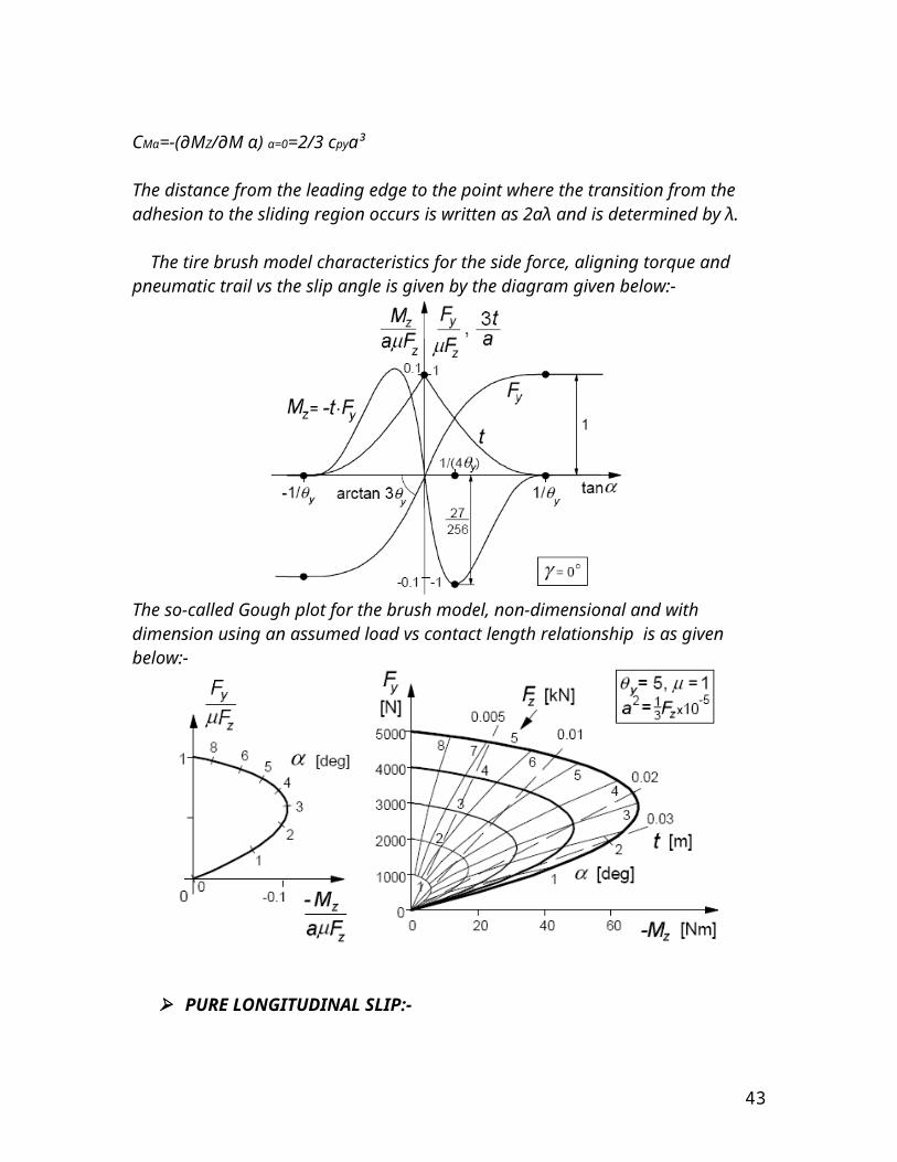
The distance from the leading edge to the point where the transition from the adhesion to the sliding region occurs is written as 2aλ and is determined by λ.
The tire brush model characteristics for the side force, aligning torque and pneumatic trail vs the slip angle is given by the diagram given below:-
35
The so-called Gough plot for the brush model, non-dimensional and with dimension using an assumed load vs contact length relationship is as given below:-
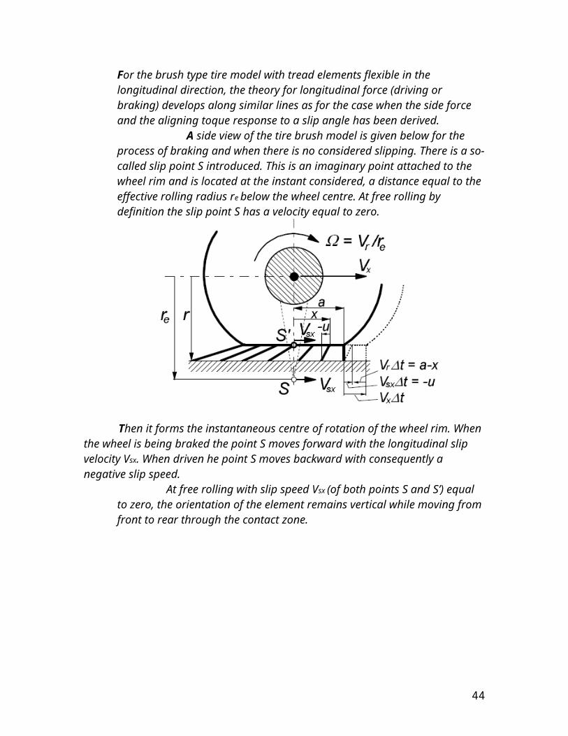
PURE LONGITUDINAL SLIP:-
For the brush type tire model with tread elements flexible in the longitudinal direction, the theory for longitudinal force (driving or braking) develops along similar lines as for the case when the side force and the aligning toque response to a slip angle has been derived. A side view of the tire brush model is given below for the process of braking and when there is no considered slipping. There is a so-called slip point S introduced. This is an imaginary point attached to the wheel rim and is located at the instant considered, a distance equal to the effective rolling radius re
below the wheel centre. At free rolling by definition the slip point S has a velocity equal to zero.
36
Then it forms the instantaneous centre of rotation of the wheel rim. When the wheel is being braked the point S moves forward with the longitudinal slip velocity Vsx. When driven he point S moves backward with consequently a negative slip speed.
At free rolling with slip speed Vsx (of both points S and S’) equal to zero, the orientation of the element remains vertical while moving from front to rear through the contact zone.
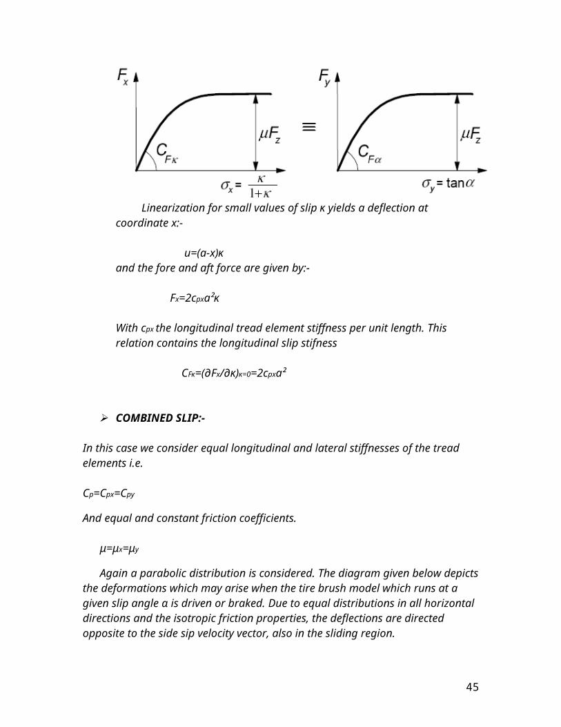
Linearization for small values of slip κ yields a deflection at coordinate x:- u=(a-x)κand the fore and aft force are given by:- Fx=2cpxa²κ
With cpx the longitudinal tread element stiffness per unit length. This relation contains the longitudinal slip stifness
CFκ=(∂Fx/∂κ)κ=0=2cpxa²
37
COMBINED SLIP:- In this case we consider equal longitudinal and lateral stiffnesses of the tread elements i.e.
Cp=Cpx=Cpy
And equal and constant friction coefficients.
μ=μx=μy
Again a parabolic distribution is considered. The diagram given below depicts the deformations which may arise when the tire brush model which runs at a given slip angle α is driven or braked. Due to equal distributions in all horizontal directions and the isotropic friction properties, the deflections are directed opposite to the side sip velocity vector, also in the sliding region.
The magnitude of the total force F now easily follows in accordance with
F=μFz(1-λ³)= μFz{3θσ-3(θσ)²+(θσ)³} for σ<σ(slip)F= μFz for σ>σ(slip)
38
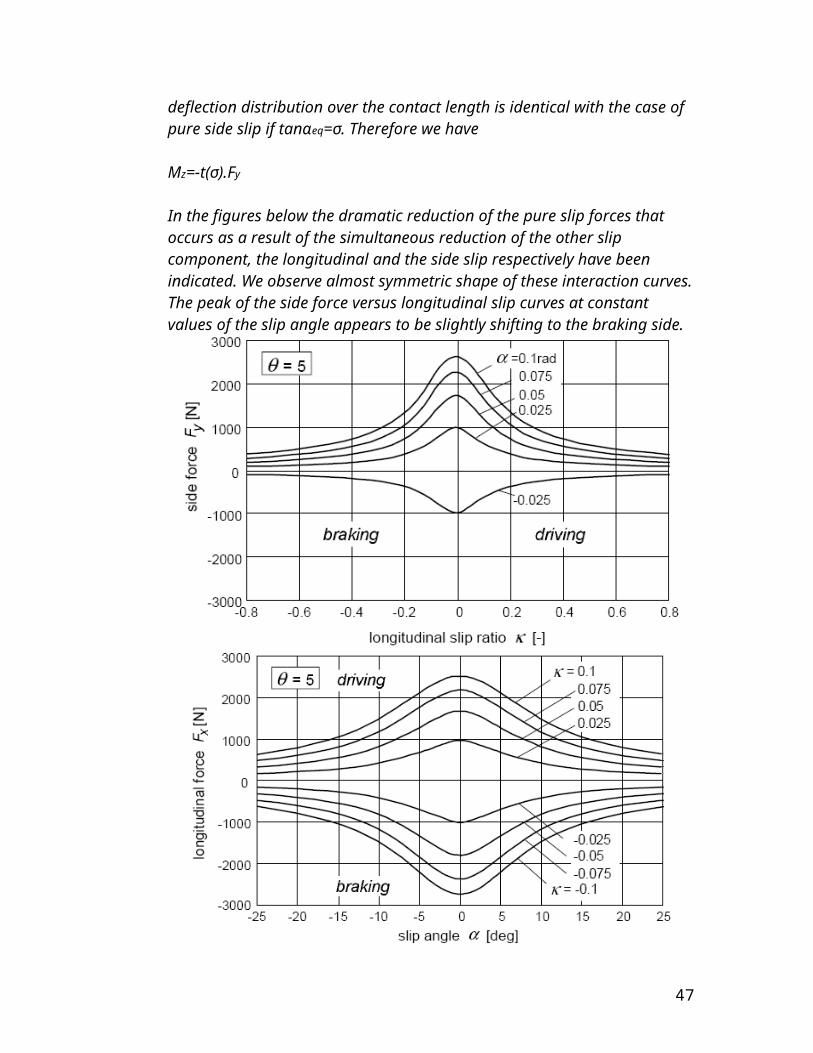
The moment –Mz is obtained by the multiplication of Fy with the pneumatic trail t. This trail is easily found when we realize that the deflection distribution over the contact length is identical with the case of pure side slip if tanαeq=σ. Therefore we have
Mz=-t(σ).Fy
In the figures below the dramatic reduction of the pure slip forces that occurs as a result of the simultaneous reduction of the other slip component, the longitudinal and the side slip respectively have been indicated. We observe almost symmetric shape of these interaction curves. The peak of the side force versus longitudinal slip curves at constant values of the slip angle appears to be slightly shifting to the braking side.
39
In the next figure the calculated variations of Fy and Mz with Fx have been plotted for several fixed values of α. Also the curves for the constant κ have been depicted. For the clarification of the nature of the Fy-Fx diagram the deflection of an element near the leading edge has been also depicted in some latter diagram. Cornering force and aligning torque are shown as functions of longitudinal force at constant slip angle α or longitudinal slip κ are shown in the figure given below.
40

As we can be seen there is a slightly nature of α curves. At braking Fy appears to be a little larger than at driving. This is atleast true for two cases one at driving and the other at braking, showing the same slip angle and the same magnitude of the deviation angle δ of the slip velocity vector and thus of the force vector with respect to the y axis.
The above figure shows the situation near the leading edge. Various deflections of an element at a distance equal to 1 from the leading edge are also shown.
Then there is shown the nature of the resulting Fy-α characteristics at a given driving or braking effort. Plotting Fy versus sin α is advantageous because the portion where wheel lock occurs is then represented by a straight line.
41
HYDROPLANING
Hydroplaning (aquaplaning) in a road vehicle occurs when a layer of water builds between the rubber tires of the vehicle and the road surface, preventing the vehicle from responding to control inputs. It becomes, in effect, an unpowered and unsteered sled.
Causes of hydroplaning:-
The ability to control a vehicle depends entirely on the friction between the tire contact points and the road surface. Every vehicle function that changes direction or speed, from turning, to accelerating, to braking, depends on the interface of those small patches of rubber and the asphalt. The higher the friction, the greater the control. An element between the tires and the road that reduces friction, then, will diminish control. If that element is nonfrictional, like water, the vehicle may lose control entirely.
A diagram of a hydroplaning tire.
The tread of a rubber tire is designed to remove water from beneath the tire, providing high friction with the road surface even in wet conditions. Hydroplaning occurs when a tire encounters more water than it can dissipate. Water pressure in front of the wheel forces a wedge of water under the leading edge of the tire, causing it to lift from the road. The tire then skates on a sheet of water with little, if any, friction, and loss of control results. If all four tires hydroplane, the vehicle will slide until it either collides with an obstacle or until wheel road friction is regained. The likelihood of hydroplaning increases with the speed of the vehicle and the depth of the water, and if the tire tread is worn, naturally low profile, or hampered by
42
underinflation. Vehicle weight is an additional factor; lighter cars hydroplane more easily. Two- or three-wheeled vehicles with round-profile tires, such as bicycles and motorcycles, virtually never suffer from hydroplaning in normal road use. The contact area with the road is a canoe-shaped patch that effectively squeezes water out of the way. Speeds of 200 mph or more are necessary to achieve hydroplaning on narrow round-profile tires.
Cruise Control:-
Cruise control poses a special danger.
Hydroplaning requires great driver awareness, both of the inital condition and in skid recovery when traction returns. A great deal of information about the car comes from the throttle pedal. If the driver isn't touching it, he may not realize that two wheels have begun to hydroplane, and may not be able to act with sufficent speed to prevent the remaining two from doing so. Loss of control is then inevitable. The action the driver must take is to disengage cruise control. This requires a button press or a tap of the brakes. The latter, if done without care, may upset the car. Both movements take additional time the driver may not have.Contrary to internet lore, however, cruise control systems do not perpetuate hydroplaning. A car has no absolute sense of speed; it determines its speed by the rate of rotation of the drive wheels. If the drive wheels have no traction, the cruise control will throttle back the engine to whatever minimal power level would be required to rotate the tires at that speed if the car was suspended on a rack. Because this response is not immediate, the drive wheels may briefly spin faster until the system compensates. Regardless, the car will slow down.
Loss of traction in low water situations:-
Hydroplaning most often occurs when there are large volumes of water on a road surface. Even slight wetness on a road, however, can cause a car to lose traction. This effect differs from hydroplaning. Tires maintain traction on the road by using a mechanism called bulk friction, where the rubber of the tire pushes down into tiny pits in irregularities of the road surface. When a road becomes slightly wet, water can fill these pits such that the water tops them off without overflowing. As the narrow strip of tire contacting the road rolls over these miniature puddles, the rubber of the tire seals the edges of the pits. Because water does not easily compress, each pit essentially has a barrier over it that prevents the rubber from pressing into it. The result is a reduction in traction. A complete loss of control, however, is unlikely.
43
TERRAMECHANICS
Terra is a shortened name for terrain and mechanics deals with the forces and their applications on the tires. Therefore the term ‘TerraMechanics’ means the study and analysis of the forces and the reactions between the terrain and the tires. The tires act in different and versatile manners according to the different types of terrains. Therefore the action of the forces attained by the motion of the vehicle on the off road terrain and therefore the action of the terrain’s granular size on the wheels and the reactions of the wheels to those terrain forces is studied in this field. The Mobility Index of the wheels is also calculated in this field. The terrains may be classified into 3 types as follows:-
Homogeneous terrain Organic terrain(muskeg) Covers with ice layers
HOMOGENEOUS TERRAIN:- If a terrain is considered to be homogeneous then the pressure sinkage relationship may take the form as below:- P=(kc/b+kφ)z^n
Where p is pressure ,b is the smaller dimension of the contact patch, the width of a contact or the radius of the circular wheel, z is the sinkage, and n , kc, kφ are the pressure sinkage parameters and kc and kφ are insensitive to the width of the rectangular plates with large aspect ratios (larger than 5-7) in homogeneous terrains. A number of test have been performed to determine the degree of the dependence of these parameters on the shape of the plates. Experimental results indicate that there are little differences between the values of these parameters obtained with a set of rectangular plates with high aspect ratios (larger than 5-7) and those obtained with circular plates having the radii equal to the widths of the rectangular plates. Because of this fact circular plates are used more commonly since they use less total load than the corresponding rectangular plates to produce the same ground pressure.
MUSKEG:-
For a commonly encountered organic terrain(muskeg) in North America there is a mat of living vegetation on the surface with a layer of saturated peat beneath it .if a pressure-sinkgae curve is plotted it can be seen that initially the pressure increase with an increase in sinkage however when the applied pressure(or load) reaches a certain level the surface mat is broken. Since the saturated peat beneath the mat is often weaker than the mat and offers lower resistance, the pressure decreases with an increase in sinkage after the surface mat is broken. The surface mat is idealized as a
44
membrane-like structure which means that it can only sustain a force of tension directed along the tangent to the surface and cannot offer any resistance to bending. The underlying is assumed to be membrane that offers a resistance proportional to its deformation in the vertical direction.
P=kpz+4mmz²/Dh
Where kp is the stiffness factor for peat, mm is the strength parameter for the surface mat, and Dh is the diameter of the contact area equal to 4A/L, where A is the area and L is the perimeter of the contact patch.
COVERS WITH ICE LAYERS:-
In the northern temperate zone, the snow and the ground is often subject to the melt-freeze cycle during the winter season. Consequently, crusts (ice layers) of significant strength form at the surface of snow covers in open areas. With subsequent snow fall on top of crusts, snow covers containing ice layers are formed. In this case the pressure first increases with the sinkage as the snow within a certain boundary under the plate is deformed. When the lower boundary of the deformation zone of the snow under the plate reaches the ice layer, the pressure increases rapidly with an increase of sinkage. When the applied pressure exceeds a certain level, the ice layer is broken resulting in a sudden drop in pressure, increasing deformation of the snow beneath the ice layer. as the ice layer approaches the frozen ground at the base of the snow cover, the pressure again increases rapidly. The preesure sinkage relationship before and after the failure of the ice layer maybe described by an exponential function. z=zw[1-exp(-p/pw)]
where zw would define the point of an asymptote if a pressure-sinkage plot would be made.
There basically three different types of soils based upon the pressure response and the hardness of their structure matrix.
DIFFERENT TYPES OF SOILS:-
Hard dry soil:-the lines of equal major principal stress are circular are approx. circular. The softer the soil the narrower the patterns become. The pressure for a normal treaded tyre is pmax=1.125pmean however this number reaches to 3 or 4 times for larger treads.
The wet soil:- since under pressure it has the ability to expand sideways therefore the stress is more concentrated to the center. Pmax=2pmean .
45

The normal intermediate soil:-this type of soil has intermediate stress reaction and similar an intermediate pressure range that comes out to be pmax=1.5pmean.
GRANULAR SIZE AND CI:- There are primarily two different types of soils based on the size of their
grains:- Fine grained soils or clayey soil:-these soils have 50 percent grains by
weight being smaller in size than 0.074mm. The fine grained soils are the soils that have 7 percent of the grains by
weight smaller than 0.074mm in size this is fairly recommended to steering, however this changes when they are weight and that is when they be unfit for large treaded tyres.
It for the above reasons and traction that the number of sets and tyre treads we employ are better suited.
The CI is the cone index and the best recommended is 3cm/s. The CI is measured by the conical penetrometer that measures the how the
behaviour of the soil would be in various stress conditions under loading.
In the table below some tyre parameters have been tabulated of some soils that are of interest.Soil n kc kφ c(lb/m²) Φ (degrees)Heavy soil 0.13 45 140 10 34Clayey soil 0.5 12 16 0.6 13Muskeg 0.7 7 14 0.3 10Dry sand 1.1 0.1 3.9 0.15 28Snow 1.44 0.3 0.05 0.87 20.7
PREDICTION OF WHEELED VEHICLE PERFORMANCE
Mobility index=(((fcp×fw)/(ft×fg))+(fwl-fcl)×fe×ft)
Where fcp is contact pressure factor, fw is weight factor, ft is tire factor, fg is grouser factor, fwl is wheel load factor, fcl is clearance factor, fe is engine factor, ft is transmission factor.
The mobility index predicts the performance of the vehicle in off road conditions.
The mobility index however depends a lot upon the traction resistance which is directly dependant upon the number of wheels employed.
The tyre behaviours:-
based upon the pressures of the tyres they are classified into two types i.e. the rigid tyre and the elastic tyres.
46
If the sum of the inflation pressure and the external pressure is greater than the critical pressure than the tyre will remain rigid.
If the sum of the inflation pressure and the external is less than the critical pressure than the tyre will be elastic and will be capable of deformation.
Both have different resistance force loading behaviours. For the rigid wheel:-
Vertical load=W=rb(∫p(θ)cos θd θ+ ∫τ(θ)sinθdθ)
Drawbar pull =rb(∫ τ(θ)cos θd θ- ∫p(θ)sin θd θ)
Wheel torque=Mω =r²b ∫ τ(θ)d θ
Where r is the radius of the tyre, the τ is the shear stress and θ is the angle it moves through. For the drawbar pull the width of the tyre is denoted by b and pressure is denoted by p. For wheel torque the moment is denoted by M.
47

FLUID MECHANICS
The amphibious vehicle since it is to access and travel across water bodies has its basis vested in the fundamental principles of Fluid Mechanics one of them being he Archimedes’ principle of Bouyancy.
Archimedes’ principle:-
Archimedes’ principle states that the buoyant force has a magnitude equal to the weight of the fluid displaced by the body and is directed vertically upward.
Or in simple terms it can be stated that the resultant fluid force acting on a body that is completely submerged or floating in a fluid is called the buoyant force.
Where the weight of the liquid displaced by the floating body may be found out by:-
Weight of fluid displaced=ρgBlD
Where ρ is the density of the fluid in which the vehicle floats, g is the acceleration due to gravity, B is the width of the vehicle, l is the length of the vehicle and D is the draught of the vehicle allowed under the conditions.
Determination of the metacentric height:-
the metacentric height of vessel can be determined if the angle of tilt θ caused by moving a load P a known distance x across the deck or the surface is measured.
Overturning moment due to movement of load P=Px
If GM is the metacentric height and W=mg is the total weight of vessel including P,
Righting moment=W×θ×GM
For equilibrium in the tilted position the righting moment must equal the overturning moment so that by comparing the above to equation we have:-
W×θ×GM= Px
48
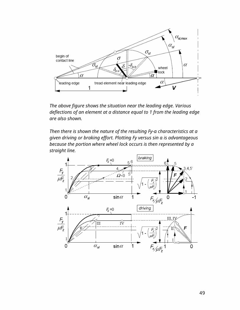
DRAG AND LIFT:-
As shown in the figure there are certain forces acting on the body. When any body moves through a fluid, an interaction between the body and fluid occurs; this effect can be described in terms of the forces st the fluid-body interface. This can be described in terms of the stresses-wall shear stresses, τw due to viscous effects and normal stresses due to the pressure p.
It is often useful to know the detailed distribution of shear stress and pressure over the surface of the body, although such information is difficult to obtain. Many times however only the integrated or resultant effects of these distribution are needed. The resultant force in the direction of the upstream velocity is termed the drag D, and the resultant force normal to the upstream velocity is termed the lift L. For some three-dimensional bodies thee may also be a side force that is perpendicular to the plane containing D and L. The resultant of the shear stress and pressure distribution can be obtained by integrating the effect of these two quantities on the body surface .
dFx =-pdAcos315+ τw sin315dA
dFy=psin315dA+ τwcos315dA
D=∫ dFx=-∫pcos315dA+∫ τw sin315dA
L=∫ dFy=∫psin315dA+∫ τwcos315dA
Of course to carry out the integration and determine the lift and drag, we must know the body shape (i.e. θ as a function along the body) and the distribution of shear stress and pressure along the surface. These distributions are often extremely difficult to obtain , either experimentally or theoretically. The pressure distribution can be obtained experimentally without too much difficulty by use of a series of static pressure taps along the body surface.
49

The angle is never 0 nor 90 along the either body. Exception is a plate aligned parallel when angle is 90 or perpendicular to the stream when angle is 0. This above described case that has been discussed is present when we analyze the fins that are placed on the outer sides of the tires for the liquid propulsions and crossing water bodies. The fins are made up of 4 plates and at the initial position the plates are placed in the perpendicular positions and the second couple in a positions that is parallel to the stream of the incoming flow.
GEARS:-
Spur gears found on a piece of farm equipment
A gear wheel is a wheel with teeth around its circumference, the purpose of the teeth being to mesh with similar teeth on another mechanical device -- possibly another gear wheel -- so that force can be transmitted between the two devices in a direction tangential to their surfaces. A non-toothed wheel can transmit some tangential force but will slip if the force is large; teeth prevent slippage and allow the transmission of large forces. A gear can mesh with any device having teeth compatible with the gear's teeth. Such devices include racks and other non-rotating devices; however, the most common situation is for a gear to be in mesh with another gear. In this case rotation of one of the gears necessarily causes the other gear to rotate. In this way, rotational motion can be transferred from one location to another (that is, from one shaft to another).
50
Mechanical advantage:-
Since the teeth of two meshing gears are locked in a one to one correspondence, when all of the teeth of the smaller gear have passed the point where the gears meet – i.e., when the smaller gear has made one revolution -- not all of the teeth of the larger gear will have passed that point -- the larger gear will have made less than one revolution. The smaller gear makes more revolutions in a given period of time; it turns faster. The speed ratio is simply the ratio of the numbers of teeth on the two gears. (Or, actually, its reciprocal.)speed A : speed B : : number of teeth B : number of teeth AThis ratio is known as the gear ratio. The torque ratio can be determined by considering the force that a tooth of one gear exerts on a tooth of the other gear. Consider two teeth in contact at a point on the line joining the shaft axes of the two gears. In general, the force will have both a radial and a circumferential component. The radial component can be ignored: it merely causes a sideways push on the shaft and does not contribute to turning. The circumferential component causes turning. The torque is equal to the circumferential component of the force times radius. Thus we see that the larger gear experiences greater torque; the smaller gear less. The torque ratio is equal to the ratio of the radii. This is exactly the inverse of the case with the velocity ratio. Higher torque implies lower velocity and vice versa. The fact that the torque ratio is the inverse of the velocity ratio could also be inferred from the law of conservation of energy. Here we have been neglecting the effect of friction on the torque ratio. The velocity ratio is truly given by the tooth or size ratio, but friction will cause the torque ratio to be actually somewhat less than the inverse of the velocity ratio. Spur gears:- Spur gears are the simplest, and probably most common, type of gear . Their general form is a cylinder or disk (a disk is just a short cylinder). The teeth project radially, and with these "straight-cut gears", the leading edges of the teeth are aligned parallel to the axis of rotation. These gears can only mesh correctly if they are fitted to parallel axles.
51

Helical gears:-
Helical gears from a Meccano construction set.
Helical gears offer a refinement over spur gears. The leading edges of the teeth are not parallel to the axis of rotation, but are set at an angle. Since the gear is curved, this angling causes the tooth shape to be a segment of a helix. The angled teeth engage more gradually than do spur gear teeth. The speed is considered to be high when the pitch line velocity (that is, the circumferential velocity) exceeds 5000 ft/min. A disadvantage of helical gears is a resultant thrust along the axis of the gear, which needs to be accommodated by appropriate thrust bearings, and a greater degree of sliding friction between the meshing teeth, often addressed with specific additives in the lubricant.
Bevel gears:-
Bevel gear in floodgate Bevel gears are essentially conically shaped, although the actual gear does not extend all the way to the vertex (tip) of the cone that bounds it. With two bevel gears in mesh, the vertices of their two cones lie on a single point, and the shaft axes also intersect at that point. 'Zero bevel gears' have teeth which are curved along their length,
52

but not angled. Spiral bevel gears have the same advantages and disadvantages relative to their straight-cut cousins as helical gears do to spur gears. Straight bevel gears are generally used only at speeds below 5 m/s (1000 ft/min), or, for small gears, 1000 r.p.mWorm gear:-
A worm and gear from a Meccano construction set
A worm is a gear that resembles a screw. It is a species of helical gear, but its helix angle is usually somewhat large(ie., somewhat close to 90 degrees) and its body is usually fairly long in the axial direction; and it is these attributes which give it its screw like qualities. A worm is usually meshed with an ordinary looking, disk-shaped gear, which is called the "gear", the "wheel", the "worm gear", or the "worm wheel". Helical gears are, in practice, limited to gear ratios of 10:1 and under; worm gear sets commonly have gear ratios between 10:1 and 100:1, and occasionally 500:1. In worm-and-gear sets, because the worm's helix angle is large, the sliding action between teeth is considerable, and the resulting frictional loss causes the efficiency of the drive to be usually less than 90 percent, sometimes less than 50 percent.
GEARS USED:-
The gears used for the transmission of mechanical power from the motors to the shafts of the vehicle are spur gear types. There is a small gear driving a large gear on each motor. The driver gear and the driven gear have a ratio of 1:6.25.The driver gear is
53
It has almost 11 teeth. There outer diameter is 1inch. The driven gear is as shown
The driven gear has an outer diameter of 5.25inches and similarly the number of teeth of the driven gear can be calculated. By interchanging their positions we can either increase the speed or increase the torque and compromise on the speed and all these change in multiples of 6.
And not that it includes in gears but due to some common type of work and shape the sprockets can also be discussed here. The sprockets that are connected to the shafts are as shown
54
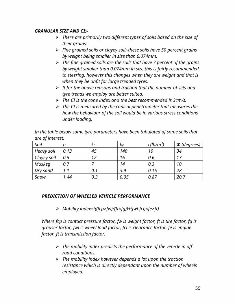
The number of teeth are as shown in the above diagram and it is these sprockets that lock into the chains and make all the tires driven.
Gear Nomenclature:-
55
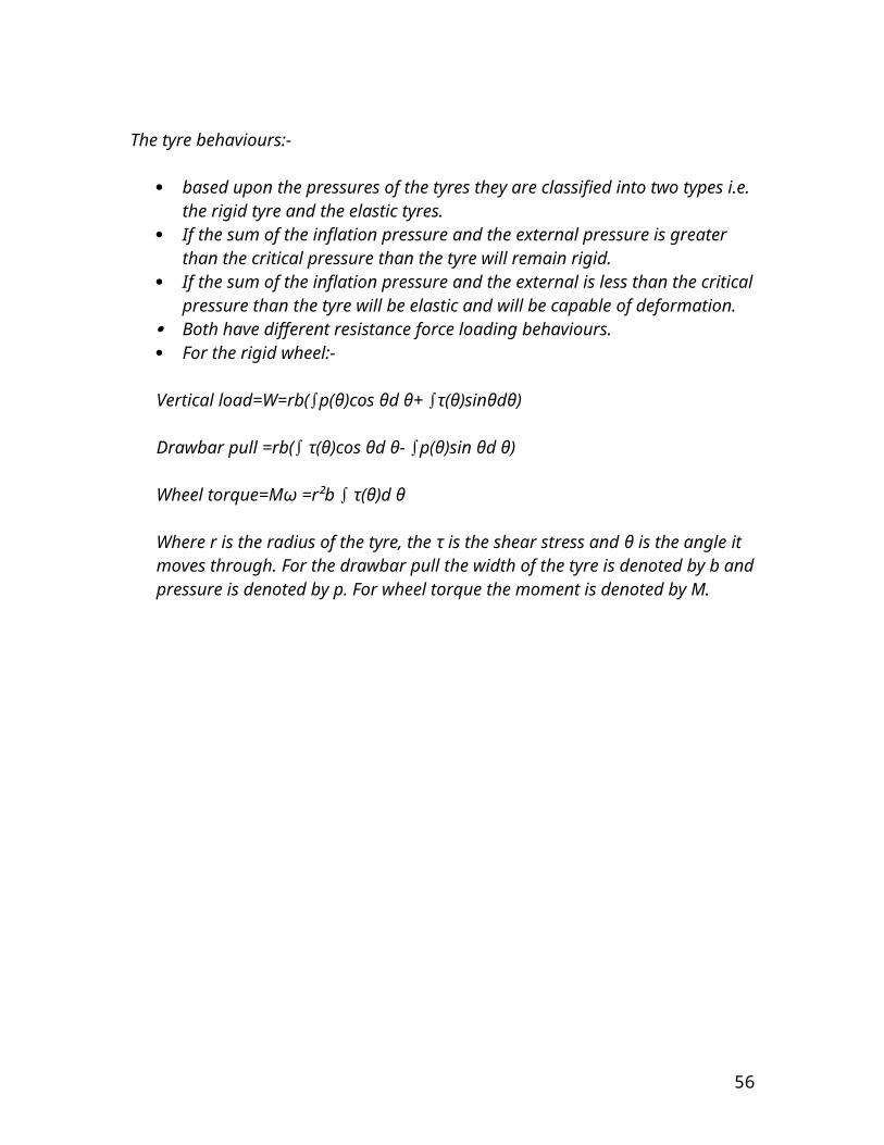
n. Rotational velocity. (Measured, for example, in r.p.m.) ω Angular velocity. (Radians per unit time.) (1 r.p.m. = π/30 radians per second.) N. Number of teeth. 'Path of contact':-
56

The path followed by the point of contact between two meshing gear teeth. 'Line of action', also called 'Pressure line'. The line along which the force between two meshing gear teeth is directed. It has the same direction as the force vector. In general, the line of action changes from moment to moment during the period of engagement of a pair of teeth. For involute gears, however, the tooth-to-tooth force is always directed along the same line -- that is, the line of action is constant. this implies that for involute gears the path of contact is also a straight line, coincident with the line of action -- as is indeed the case. Further note on tooth force56 'Axis':- The axis of revolution of the gear; center line of the shaft. 'Pitch point' (p):- The point where the line of action crosses a line joining the two gear axes. 'Pitch circle':- A circle, centered on and perpendicular to the axis, and passing through the pitch point. Sometimes also called the 'pitch line', although it is a circle. 'Pitch diameter' (D):- Diameter of a pitch circle. Equal to twice the perpendicular distance from the axis to the pitch point. The nominal gear size is usually the pitch diameter. 'Pitch surface':- For cylindrical gears, this is the cylinder formed by projecting a pitch circle in the axial direction. More generally, it is the surface formed by the sum of all the pitch circles as one moves along the axis. Eg., for bevel gears it is a cone. 'Angle of action':- Angle with vertex at the gear center, one leg on the point where mating teeth first make contact, the other leg on the point where they disengage. 'Arc of action':- The segment of a pitch circle subtended by the angle of action. 'Pressure angle' (ø):- The complement of the angle between the direction that the teeth exert force on each other, and the line joining the centers of the two gears. For involute gears, the teeth always exert force along the line of action, which, for involute gears, is a straight line; and thus, for involute gears, the pressure angle is constant. 'Outside diameter' (Do):- Distance from the gear center to the tops of the teeth. 'Root diameter':- Distance from the gear center to the bottoms of the troughs between teeth. 'Addendum' (a):- The radial distance from the pitch surface to the outermost point of the tooth. a = Do - D. 'Dedendum' (b):- The radial distance from the depth of the tooth trough to the pitch surface. b = D - root diameter. 'Whole depth' (ht):- Addendum plus dedendum; or, equivalently, outside diameter minus root diameter. 'Clearance':-
57
The amount by which the dedendum of a gear exceeds the addendum of the gear it is mating with.
'Working depth':- The depth of engagement of two gears. It equals the sum of their addenda. 'Circular pitch' (p):- The distance from one face of a tooth to the corresponding face of an adjacent tooth on the same gear, measured along the pitch circle. 'Diametral pitch' (P):- The ratio of the number of teeth to the pitch diameter. Eg., could be measured in teeth per inch or teeth per centimeter. 'Base circle':- Applies only to involute gears, where the tooth profile is the involute of the base circle. The radius of the base circle is somewhat smaller than that of the pitch circle. Base pitch (pb):- Applies only to involute gears. It is the the distance from one face of a tooth to the corresponding face of an adjacent tooth on the same gear, measured along the base circle. Sometimes called the 'normal pitch'. 'Interference':- Contact between teeth other than at the intended parts of their surfaces. 'Interchangeable set'. A set of gears, any of which will mate properly with any other.
BACKLASH:- Backlash is the error in motion that occurs when gears change direction. It exists because there is always some gap between the tailing face of the driving tooth and the leading face of the tooth behind it on the driven gear, and that gap must be closed before force can be transferred in the new direction. The term "backlash" can also be used to refer to the size of the gap, not just the phenomenon it causes; thus, one could speak of a pair of gears as having, for example, "0.1 mm of backlash." A pair of gears could be designed to have zero backlash, but this would presuppose perfection in manufacturing, uniform thermal expansion characteristics throughout the system, and no lubricant. Therefore, gear pairs are designed to have some backlash. It is usually provided by reducing the tooth thickness of each gear by half the desired gap distance.
Tooth profile:-
As mentioned near the beginning of the article, the attainment of a non fluctuating velocity ratio is dependent on the profile of the teeth. Friction and wear between two gears is also dependent on the tooth profile. There are a great many tooth profiles that will give a constant velocity ratio, and in many cases, given an arbitrary tooth shape, it is possible to develop a tooth profile for the mating gear that will give a constant velocity ratio. However, two constant velocity tooth profiles have been by far the most commonly used in modern times.
58

They are the cycloid and the involute. The cycloid was more common until the late 1800s; since then the involute has largely superseded it, particularly in drive train applications. The cycloid is in some ways the more interesting and flexible shape; however the involute has two advantages: it is easier to manufacture, and it permits the center to center spacing of the gears to vary over some range without ruining the constancy of the velocity ratio. Cycloidal gears only work properly if the center spacing is exactly right. Cycloidal gears are still used in mechanical clocks.
Gear materials:- Numerous nonferrous alloys, cast irons, powder-metallurgy and even plastics are used in the manufacture of gears. However steels are most commonly used because of their high strength to weight ratio and low cost.
BASIC LUBRICATED FRICTION MODES
59
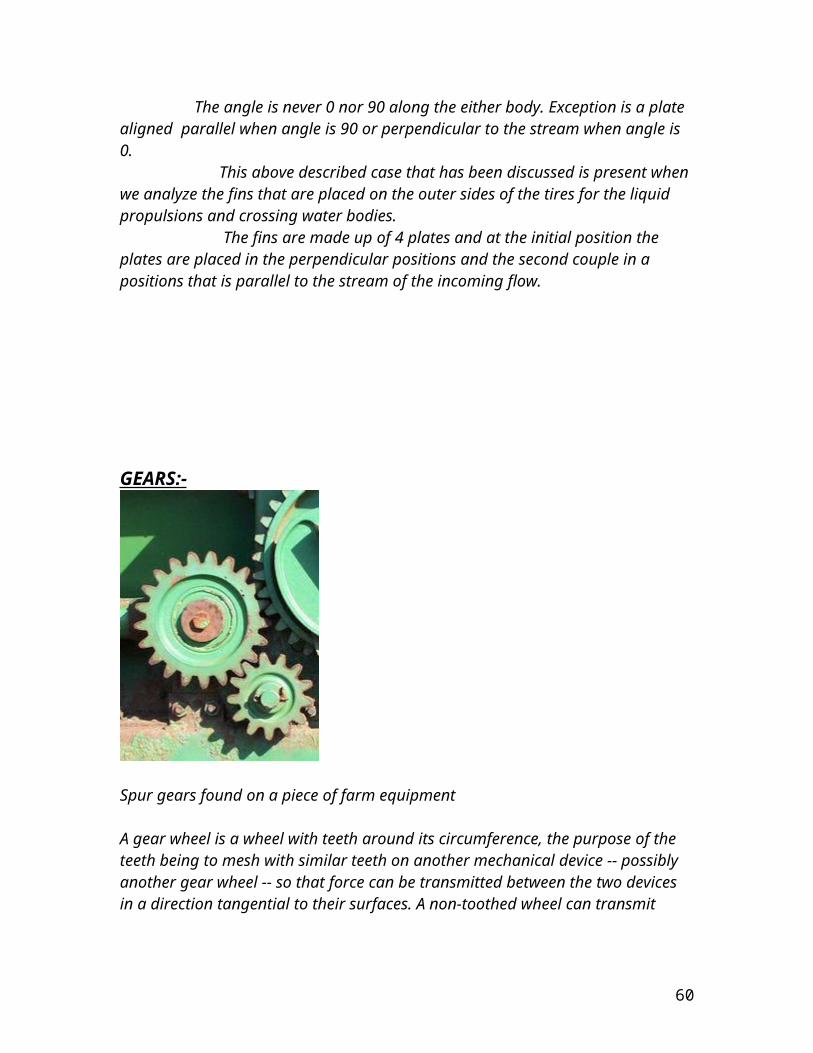
Lubrication friction is basically of two types:-
The boundary layer lubricated frictional contact.Elastohydrodynamic lubricated frictional contact.
60
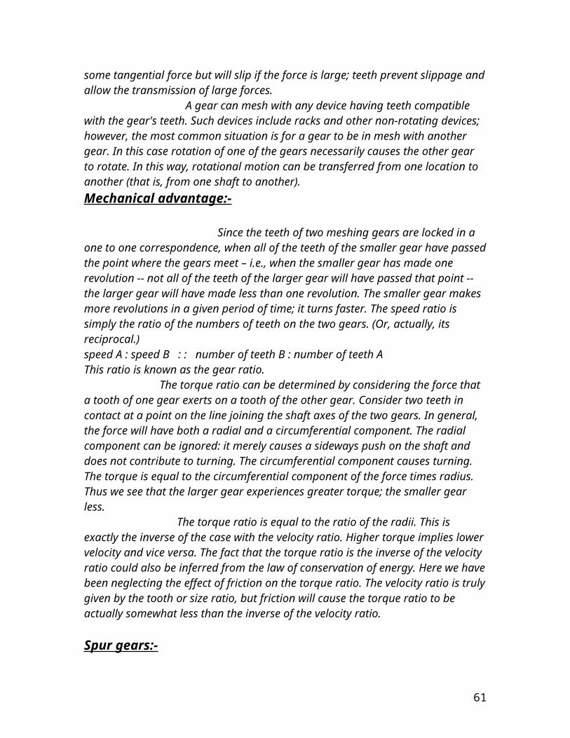
The former mode occurs when the velocity is very low, and therefore it produces a large friction force, when rubber is the upper surface. At the opposite extreme is the situation of the elastohydrodynamic lubricated friction. Here the velocity is high and if rubber is the upper surface two phenomena are operative. First an elastic indentation of the rubber develops due to lubricant accumulation at the leading edge of the upper body. The inertia and viscosity-induced retardation of lubricant displacement account for the resulting indentation. Second, this accumulation generates an upward pressure. The net result of this is a drastic reduction in friction force. This latter situation is a special case of hydrodynamic lubrication. It is called elastohydrodynamic lubrication, often abbreviated as EHL. The name derives from the elastic indentation of one body in the frictional contact region. When there are two type of frictional contacts taking place in the same tire then this type of frictional sliding is called as a mixed lubrication mode: part boundary, part EHL. At higher velocities the entire body would be in the full EHL regime with no boundary type contacts. The full separation causes the normal force to be borne by fluid pressure with very low frictional force. At sufficiently high velocities with two equally hard bodies a pure hydrodynamic lubrication mode can exist. No indentation is involved. Another important effect is the Squeeze Film phenomenon. If a low-hardness upper body vertically approaches a lubricated hard countersurface at a sufficiently high velocity, a pocket of lubricant may be momentarily trapped in the central contact region. During the period before the lubricant is expelled from the pocket, an upward pressure is sustained by the trapped lubricant. Tangential motion during this period is easily accomplished since the frictional retardation force is small due to the trapped lubricant.
MECHANICS OF WATER TIRE INTERACTION:-
The application of hydrodynamic and squeeze film concepts to the traction of tires is clarified by considering the “three-zone concept”, the “water wedge” is formed due to the displacement inertia of the intercepted water film. In zone center of tire patch a mixed lubrication regime exists that is part hydrodynamic, part boundary. In the trailing zone of the contact tire the boundary-layer lubrication is dominant. The general traction versus speed relationship of tires can be explained on the basis of the three-zone concept. The zones will vary in length according to test conditions and traction performance will depend upon the relative size of the zones. The squeeze film concept is of primary importance in the investigation of traction. The time taken for a particular tread element to squeeze through the water film depends on the dimensions of a tread element, the force on the element, initial film thickness, load, water viscosity and surface texture, but is independent of speed. The time of traversal of the tread element through the entire contact zone varies inversely with speed. The three-zone concept of the contact length is valid below a certain critical speed. Above this speed an element entering the contact zone sweeps through it before there is time to squeeze through the water film, and a condition described as “total” viscous or thin-film hydroplaning occurs. At speeds below this critical speed “partial”
61
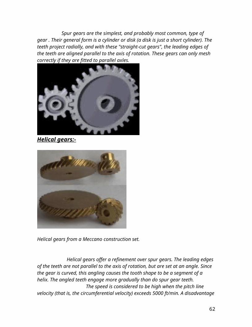
thin-film hydroplaning can occur which generates areas of hydrodynamic pressure that support part of the tire load. Although the three-tire zones have been postulated, the types of rubber-pavement contact in the footprint are of two types in any local area, either hydrodynamic(EHL) or boundary layer. EHL dominates in the leading zone of the tire contact patch out of the three discussed patches, boundary layer in the trailing zone at speeds short of full hydroplaning. The middle zone is a mixture of both the types and is therefore designated as the mixed zone. On this basis a measured traction coefficient is determined by the relative proportions of these two modes.
TIRE WET TRACTION BEHAVIOUR:- In light of the ongoing discussion on the performance of tire on the road, it is imperative to note that there are different types of tire behavior for different types of road and off road conditions. The tire and therefore the vehicle in motion behaves very differently in the dry conditions and quite differently in the wet road conditions. Same is the case with a less debatable issue of tires’ different behavior in the rocky terrain and dry off road, and it behaves in a totally different manner in the marshy and the damp terrain where the water depth is significant enough to play a critical role in the behavior of the tire function. The main issue that arises when we deal with such versatile range of terrains is that the tire should be of a width that would avoid sinking in the soil and at the same it would not pose a significant value of traction. Since we are designing the vehicle in a manner that is to accommodate motion in water aswell therefore we must note that when the vehicle moves into the water region of its path we transcend our approach from a view of Terra mechanics to one of fluid mechanics since at even a small magnitude of velocity the liquid poses an appreciable amount of drag.
In light of the vehicle versatility we shall discuss some key design feature of tire:-
62

Construction that is radial versus bias and other mechanical construction features.
Tread compound properties and composition Tread pattern
DRY VERSUS WET ROAD OPERATION:-
In some circumstances wet traction is not substantially lower than dry traction. This is why all vehicles donot immediately skid off the road at the beginning of a rainshower. Laboratory measurements of wet and dry friction on reasonably rough textured surfaces verify the minimal difference of dry versus wet.
At low slip in the 0 to 0.2 range(0 to 20 percent) the wet and dry curves are equivalent. At high slip equally at 1.0 (100 percent) or full slide, the wet traction level is substantially lower than dry. But this is the case for a moderately textured surface and with a pressurized distribution of water on the surface. Under such conditions the type of frictional lubrication in the tire contact region is mainly boundary layer. In the low slip range the relative velocity of tread element versus test surface is low and the element sinkage rake is sufficiently high to give reasonably good boundary-type contact. In such case very low EHL is present.
At full or 100 percent slip, the relative velocity of tread surface elements versus lubricated test surface is sufficiently great to produce some reasonable degree of elastohydrodynamic lubrication and consequently a loss in traction. A similar situation exists for cornering. It should be noted at this stage that there exists essentially an equivalent amount of lateral force for all speeds and surfaces (wet or dry) in the range of 0 to 4 degrees angle. Thus in both the cornering and braking in the low slip regime, there is no significant difference between wet and dry surfaces over a broad range of speeds, water depth and texture for these particular tires. There is some very small difference for the(low traction) wet painted asphalt at32 kmh or 20mph. A greater difference would be expected at higher speeds.
TRACTION
63

Refers to the friction between a drive member and the surface it moves upon, where the friction is used to provide motion. For the purposes of driving a wheeled vehicle, high friction is generally desired, as it provides a more positive connection between the driving and driven members. In contrast, motion in a geared mechanism is provided by interference, and friction is usually detrimental because the gear mechanism has intrinsic sliding, and sliding under friction causes heating losses. Traction between two surfaces usually depends on several factors including:-
Material properties of each surface. Macroscopic and microscopic shape or "roughness". Force of contact. Area of contact. Contaminants at the material boundary including lubricants and adhesives.
Formula for friction:-
A common approximation is F=μFN. Here, μ summarizes material properties and roughness and is called "the coefficient of friction". FN is the normal force, which is applied perpendicular to the contact. In a simple system in equilibrium, such as a mass sitting on a surface, the normal force is equal to mass multiplied by gravitational acceleration (FN = mg). The statement of this expression is that friction is directly proportional to the intrinsic friction caused by the materials and contaminants; and that friction is also directly proportional to the force. In practice, this is an approximation but in many situations other factors, e.g., the area of contact, play a role.
Friction trade-offs:-
In most applications, there is a complicated set of trade-offs in choosing materials. For example, soft rubbers often provide better traction but also wear faster and have higher losses when flexed -- thus hurting efficiency and sometimes causing early failure due to heat build-up. Subtle choices in material selection may have a dramatic effect. For example, tyres used for track racing cars may have a life of 200 km, while those used on heavy trucks may have a life approaching 100,000 km. The truck tyres have worse traction and also thicker rubber, but the race car tires cannot simply use thick rubber without compromising weight, heat build-up, and so on. Traction also varies with contaminants. A layer of water in the contact patch can cause a substantial loss of traction. This is one reason for grooves and siping of automotive tyres: most water must be displaced from the contact, but inertial effects limit the speed with which it can be displaced. Grooves hurt dry traction but reduce the distance the water travels to escape. Note there are applications where the
64
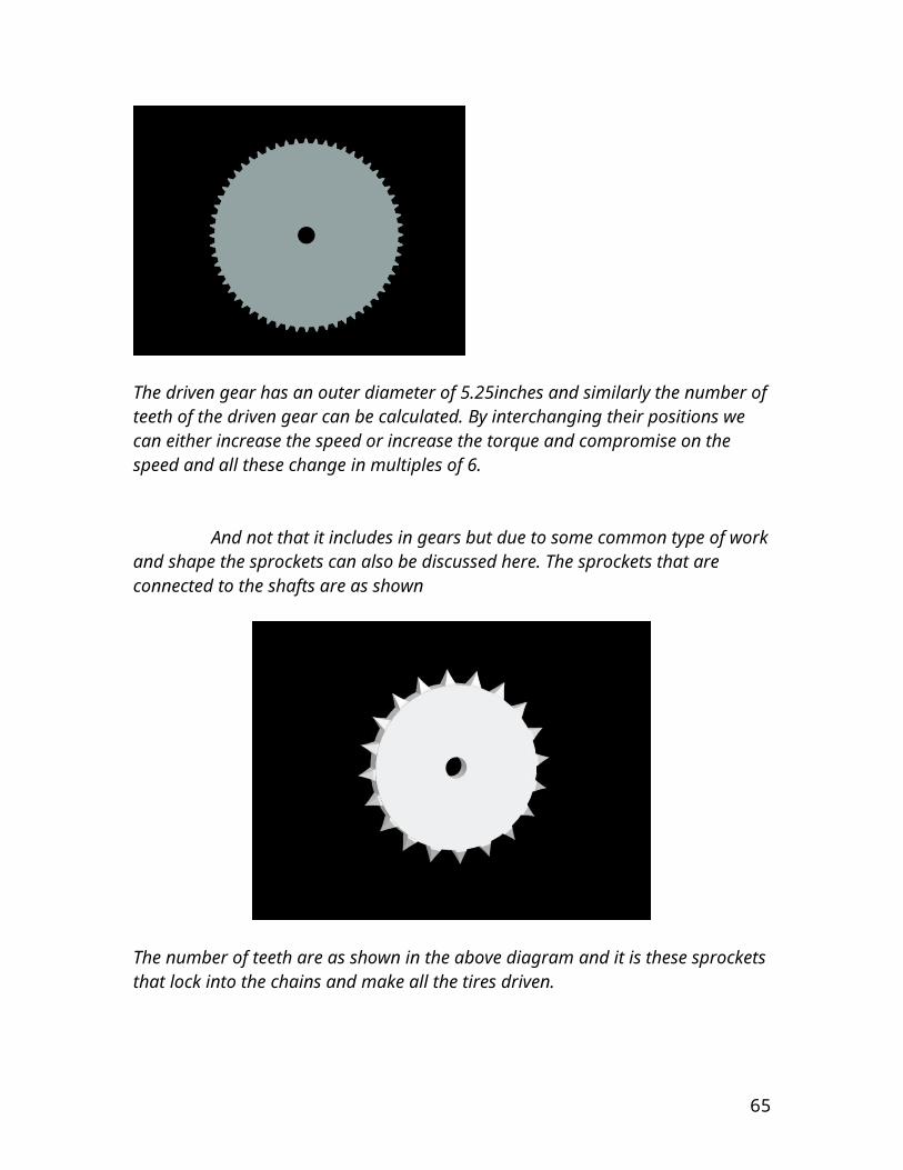
distances are already short, for example bicycle tires have a narrow and pointed contact and so even slick tyres give good traction on a wet pavement. Where the roadway surface is substantially flexible or malleable, tread can also form divots in the road, leading to interference-type traction (as in gears) rather than friction. Traction applies across a wide variety of materials and scales. For example, railroad locomotives use steel wheels on steel rails to provide traction; slot cars use rubber on plastic; and so on.
Traction boundary condition:-
Particularly in the context of the finite element method, a traction boundary condition is a portion of the boundary of a body for which forces—tangential, normal, or both—is prescribed.
Traction forces in a system:-
The traction force is given by:Traction Force = Driving Torque/Radius of Wheel. Using conservation of energy, we are aware that F=ma and hence P=Fv or rate of work done. In order to calculate power:PE = dTF / dt + dPL / dt where Pe = Efficient Power, PL = Power Loss during mechanical conversion, and TF = Traction Force.
Maximizing multi-wheeled vehicle traction:- It is important due to broad application to point out the specific case of multi-wheeled vehicles or vehicles with multiple contact patches between the tyre and the road surface. The constant coefficient of friction approximation is not adequate to describe real world maximum traction situations. If the normal force is increased, per given area of contact patch, the coefficient of friction decreases and as the normal force decreases, the coefficient of friction increases. If this were not true, then increasing tyre width, lowering tyre air pressure or increasing tyre diameter (all of which increase the area of the contact patch) would have little effect. The importance of having a coefficient of friction with the above properties has significant implications in multi-wheeled vehicle handling. The case of two wheels sharing a given normal force is particularly important in vehicle design. Two identical tyres sharing a common load achieve maximum traction when they share the load equally. Likewise, an unequally loaded pair of tyres sharing a common load will not be able to achieve the same maximum traction. Consider the "traction pair". The less laden tyre’s coefficient of friction has increased but it’s load has decreased resulting in a modest drop in traction. Conversely, the heavier laden tyre’s coefficient of friction has decreased and even though it’s traction has increased, it is not enough to make up for the drop in traction of the less laden tyre. Put another way, when unbalanced, the heavier laden tyre’s traction increases less than the less laden tyre’s decrease in traction.
65

A vehicle has balanced or neutral handling when the front and rear pairs of tyres achieve maximum traction proportional to the normal force on each pair of tires. Example: If 60% of a vehicle's total normal force is at the front of the vehicle, then 60% of the traction should also need be in the front for balanced handling. This can be achieved by a number of means. Achieving balanced handling is non-trivial due to the dynamic forces involved such as changing corner radius, bank, braking, acceleration, aerodynamic loading and coefficient of friction changing factors such as road surface debris, moisture, temperature etc. Automotive engineers attempt to minimize the effect of non-linear forces as much as possible in order to simplify design considerations.
TEXTURE AND WET TRACTION:-
In the figures provided the cornering wet traction data are plotted versus speed for tires with two tread pattern types and for two pavement textures. The closed and open tread patterns are respectively a typical seven rib highway tire with 20 percent groove void and a block tread patter with 40 percent groove void area.
The first graph for high texture surface, the closed pattern gives higher μc values compared with the open pattern in the 40 to km/h speed range. At 96 km/h or 60
66
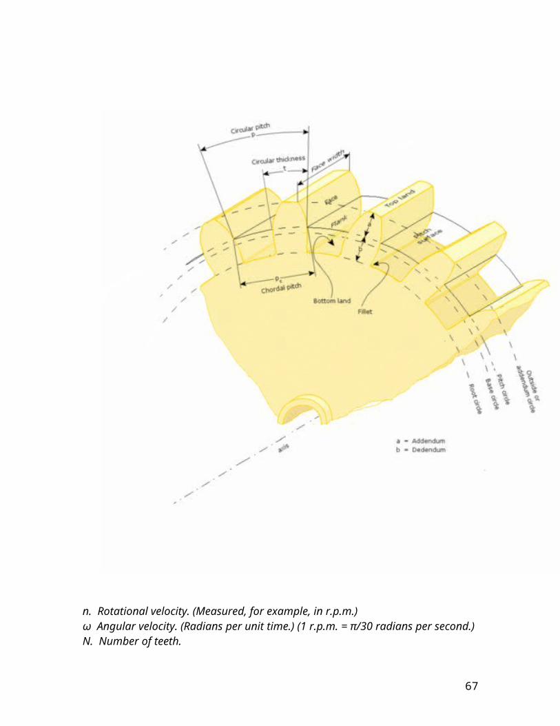
mph it is slightly inferior. Appended to each cure is the velocity of the cornering coefficient in mph. In the second graph the situation is quite different. The closed pattern is now superior to the open pattern only below 55 km/h and at 96 km/h a considerable difference exists in favour of the open pattern. It is necessary to specify the pavement texture and speed (an additional factor is water depth which was held constant). If pavement texture is specified a large variation in relative rating still exists including outright reversals. Therefore in saying so the need for the understanding of the “critical value” concept is stressed upon. Most skid pads are configured with the turn radii that produce vehicle spin out speeds in the range 55 to 65km/h or 30 to 40 mph .The curves clearly show that this speed range encompasses the crossover point. In this speed range most tires will give equivalent wet traction performance irrespective of their high-speed performance .Such tests are of little realistic value. A similar situation exists with respect to braking traction versus speed. The second figure clearly indicates the influence of water depth versus speed and thus a verification is well established for the rationale of selecting low-texture, low-skid number pavements, high speeds 96km/h or 60 mph and relatively deep water 1.5 to 2mm for meaningful wet traction tire performance.
TIRE CONSTRUCTION EFFECTS:-
The influence of tire construction on wet traction has only recently been well documented. Construction variables may be divided into two categories ,primary and secondary .Primary encompasses the basic mechanical construction types that is radial belted-bias and bias(or diagonal) .Secondary variables include such factors as carcass angles ,and the stiffness of the belt reinforcing materials. It has been found on both high and low skid resistance surfaces that no significant difference exists among radial, belted-bias, and bias tires in peak on slide wet braking traction at 64 and 96 km/h or 40 and 60 mph test speeds. The very slight belted-bias and bias advantage for slide traction is offset by an equivalent performance advantage for radial tires in the peak traction mode. The overall performance is equivalent for all three types. After readings and test it has been concluded that in radial tires there is no influence of belt angles in the range of 16 to 28 degrees. Consistent with this finding are test results on the comparison of steel ,fiber glass, and aramid belts in radial tires. The belt material made no significant difference in combined peak and slide traction ratings. Many other results on the influence of carcass angles in belted-bias tires show no significant effect over a broad range of carcass angles. Radial tires allow more open(high void) tread patterns and the superiority of radial tires in many well known results is due to this factor and not construction.
THE TREAD COMPOUND:-
67
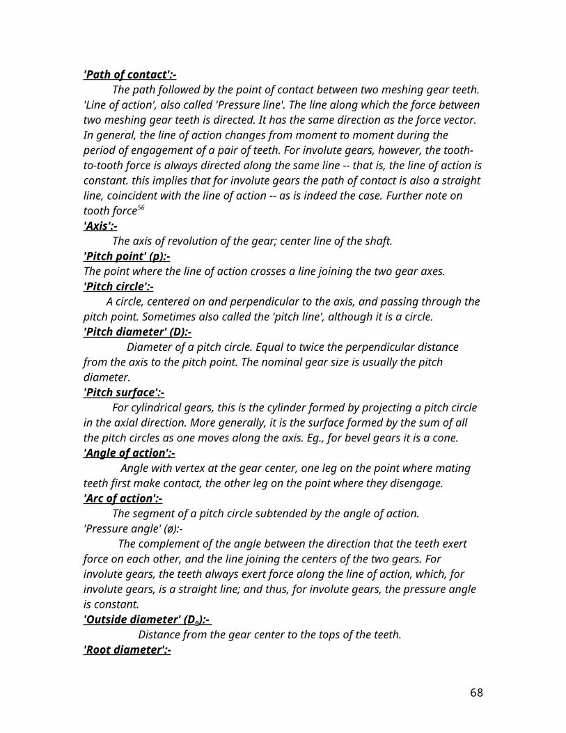
The influence of the tread compound in wet traction may be approached along two separate lines:-
On the influence of compound modulus or hardness and hysteresis properties. On the basis of the nature of the material that constitute the tread.
Tread hardness is important and conflicting results as to its influence are quoted in the literature. In the laboratory level experiments it has been found that the traction coefficient increases with the decreasing hardness.
The graph shown above is a plot of wet cornering coefficient as a function of hardness measured on the warmed up tire. The tests were at 80km/h or 50mph on smooth pebbles with external water application. The rubbers fall into essentially three groups:-
Butyl or isobutene-isopropene (IIR) rubber Styrene-butadiene (SBR) rubber Natural rubber (NR) and cis-polybutadiene (BR) rubber
Each of these groups has a different but direct dependence of traction on hardness. This grouping shows quite strongly that one cannot generalize and use hardness as an omnibus tread parameter for wet traction performance; a tread off 55 durometer hardness can have a varying traction performance depending upon which rubber is used. Each rubber has a characteristic performance level which is a function of its chemical structure and properties.
Hysteresis or its reverse resilience also effects wet traction performance
As tread elements are deformed in the contact mechanical energy is converted into heat by hysteresis mechanism.
68
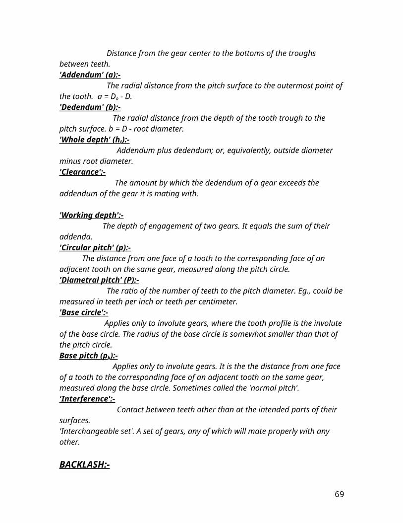
The above figure indicates that the type of rubber used for the tread will influence wet traction performance in addition to the hardness. It has been shown for SBR, NR, BR and to some extent EPDM (an ethylene propylene diene monomer rubber) the wet traction performance is directly correlated with the glass transition temperature,Tg, with one marked exception ,butyl rubber. In general the hysteresis of a rubber follows the Tg value.
TIRE TREAD PATTERN:-
The influence of tread pattern on wet traction has consistently been shown to be important. Most tread are based on circumferential ribs separated by grooves which must be wide enough to accommodate the displaced water developing a hydrostatic pressure between the rib surface and the road surface. It is generally accepted that the rib surface the road surface. It is generally accepted that the rib width should be as small as practical and the adjacent groove preferably straight so as not to impede the flow of water. Block tread patterns may be considered as essentially straight rib(or groove) patterns, with the ribs interrupted by “transverse” grooves cut at varying transverse angle. In a recent comprehensive case test and study the fractional groove volume concept was developed .This includes the effects of number of ribs, grooves and tread depth.
“Fractional groove volume” φv is defined as the fraction of the total volume occupied by the grooves referenced to volume encompassed by:-
The developed on in-road-contact tread width (dTW)
69
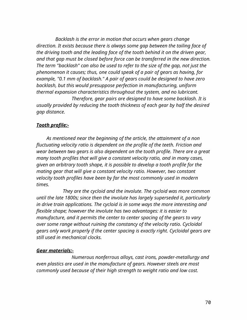
An arbitrary reference depth dimension ho which is 10mm. it may be calculated in practice by measuring the fraction groove area Φa of a footprint impression and the tread hG millimeters
Φv = Φa hG /10
It has been noticed that for the 64 and km/h values there is gradual rise in the slide wet traction values. However for the value of 32km/h or 20mph there is an initial rapid rise in the sliding wet traction which reaches a general plateau level at about the fractional groove volume of 0.08. On both surfaces and at all speeds the distinguishing feature is the attainment of a maximum or limiting value of the sliding wet traction as the tread groove void is increased.
The model
The initial model was created on proe. Many different designs were created. Initially the propulsion was to be provided by fins , of xray material, attached between two small size bicycle tires but this design was not successful because of unwanted weight of a total of 12 tires each weighing 1.25kg. Secondly the stress analysis of the fins showed that the fins sheared at high forces. Hence the following design was established.
70

In the improved model the fins(cast iron)+the tire weigh less than 1kg reducing the weight of the vehicle significantly + providing improved propulsion with the new fin design. This model was then imported to MSC ADAMS for further analysis regarding road tire interaction.
GRAPHICAL DESCRIPTION OF SOME FORCES
The longitudinal force is the force in reaction to motion to in forward direction or the force in the direction of braking or driving, normally taken to be in the x-direction. The below plot is shown for the vehicle moving left, in this case the right tread i.e. tires1,4and 5 are moving forward and the left tread i.e.tires2,3and 6 are moving backwards. The tire number is basically allocated by ADAMS software in which these graphs have been plotted. Tires 3 and 4 are at the middle of each tread. The MSC ADAMS plots have tire1 as colored red lines, tire 4 as colored black, tire 5 as green, tire 2 as blue, tire 3 as pink, and tire 6 as light blue.
71
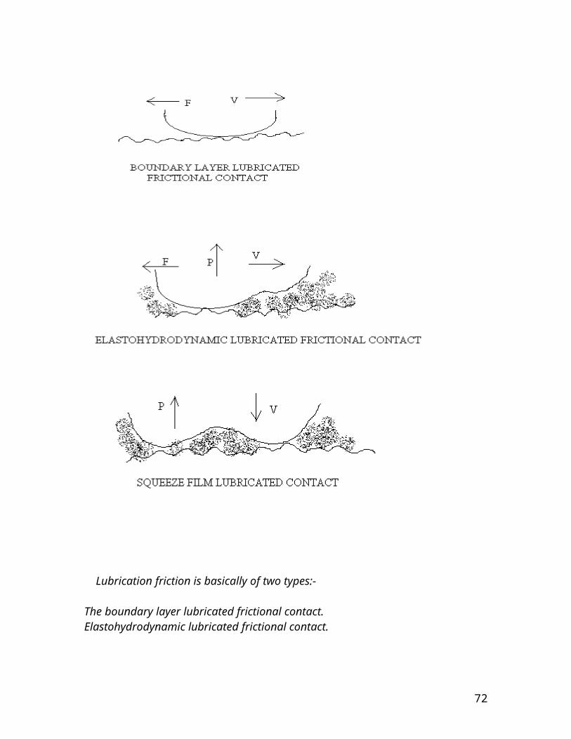
And for moving straight
72
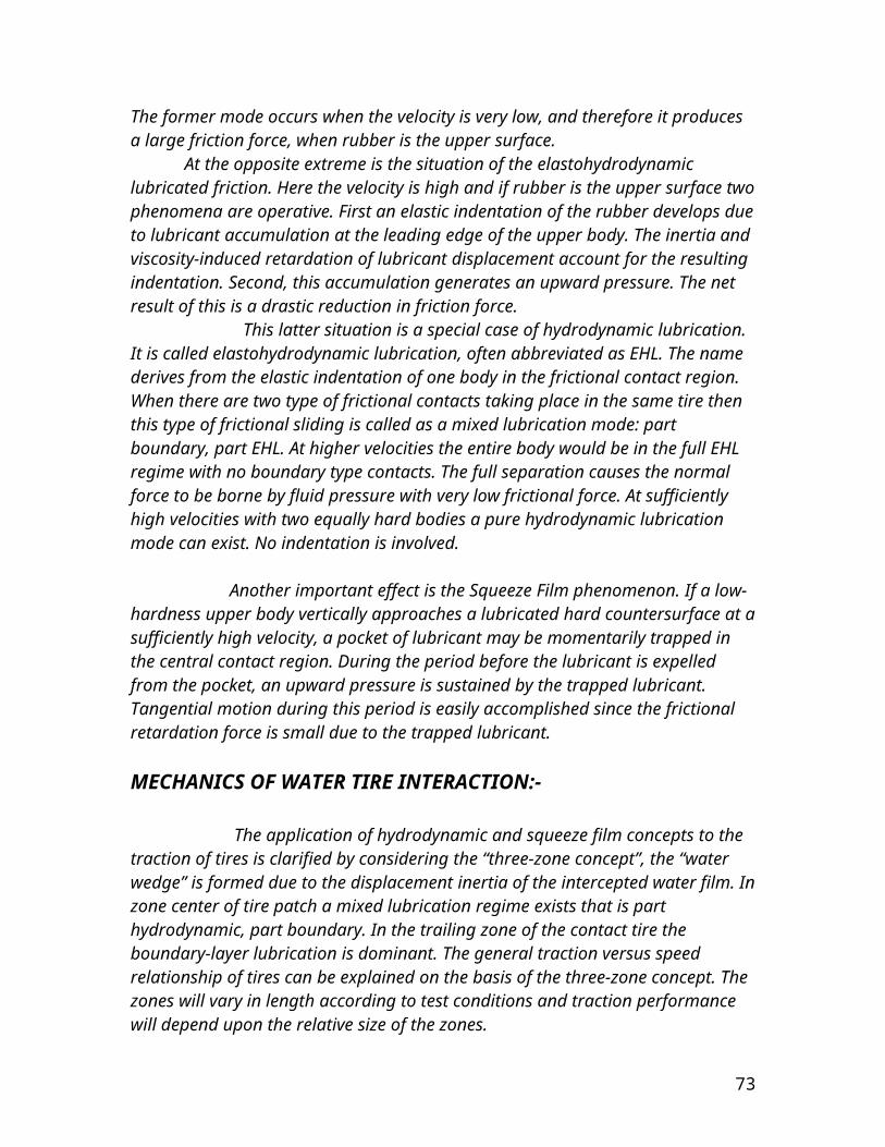
Inclination angle for left turning
for moving straight
73

The rolling resistance for moving left comes out to be
As for moving straight forward
74
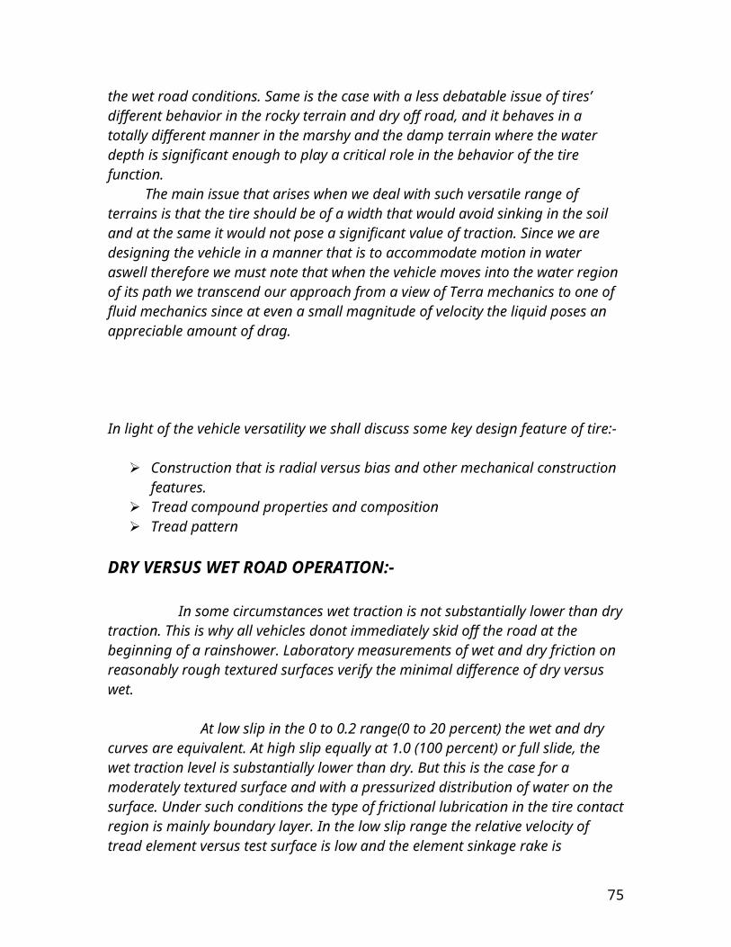
The aligning torque for moving left can be graphically represented as
And that for moving straight forward can be shown as
75
for the vehicle moving left the lateral slip
And the longitudinal slip comes out to be
76
the longitudinal slip while the vehicle moves straight would therefore be
And the lateral slip becomes
77
ELECTRONICS EQUIPMENT
The electronics equipment that is being employed here is independently out of our field of expertise therefore the fabrication and designing of the electronic equipment was in its essence out of the question. We opted for an already present electronic system. This choice resulted in the employment of the circuit in the remote control car toys. A four input was required because we needed 4 functions to be performed. One of the major drawbacks of not getting the required motors resulted in an increament of the voltage input to multiple times. Since we first decided to go for speed instead of torque therefore we achieved a fair speed at even an input of 12volts however the torque required to overcome the traction of the tires and the road was not acquired and so we opted for torque and since the gear ration between the driven and the driving gear was 6:1 therefore the speed reduced by 6 times. To acquire motion across water bodies we had to achieve a larger amount of speed. Having said this we therefore increased the input to 24volts. The input to the electronic circuit that is standard is 9volts therefore we had to modify the receiver circuit. To ICs have been placed in parallel.The IC model number is L7809. These ICs step down the voltage from 24volts to the required 9 volts. The stepping down process results in heated up ICs, however this side effect can be taken care of by adding a heat sink. There are four 9 volt relays operating 4 24 volt relays. These 24 volt ICs operate the two motors to perform the 4 functions as stated.
RELAYS:- Relay is an electrical switch that opens and closes under the control of another electrical circuit. In the original form, the switch is operated by an electromagnet to open or close one or many sets of contacts. It was invented by Joseph Henry in 1835. Because a relay is able to control an output circuit of higher power than the input circuit, it can be considered, in a broad sense, to be a form of an electrical amplifier. An electrically controlled mechanical device that opens and closes electrical contacts when a voltage (or current) is applied to a coil. A relay provides isolation of control signals from switched signals. A Solid State relay is a switching device that completes or interrupts a circuit electrically and has no moving parts. A Mechanical relay is an electromechanical device that closes contacts to complete a circuit or opens contacts to interrupt a circuit.
78
MOTORS:-
An electric motor converts electrical energy into mechanical energy. The reverse task, that of converting mechanical energy into electrical energy, is accomplished by a generator or dynamo. Traction motors used on locomotives often perform both tasks if the locomotive is equipped with dynamic brakes. Electric motors are found in household appliances such as fans, fridges, washing machines, pool pumps and fan-forced ovens. Most electric motors work by electromagnetism, but motors based on other electromechanical phenomena, such as electrostatic forces and the piezoelectric effect, also exist. The fundamental principle upon which electromagnetic motors are based is that there is a mechanical force on any current-carrying wire contained within a magnetic field. The force is described by the Lorentz force law and is perpendicular to both the wire and the magnetic field. Most magnetic motors are rotary, but linear motors also exist. In a rotary motor, the rotating part (usually on the inside) is called the rotor, and the stationary part is called the stator. The rotor rotates because the wires and magnetic field are arranged so that a torque is developed about the rotor's axis. The motor contains electromagnets that are wound on a frame. Though this frame is often called the armature, that term is often erroneously applied. Correctly, the armature is that part of the motor across which the input voltage is supplied. Depending upon the design of the machine, either the rotor or the stator can serve as the armature.
A simple DC electric motor:- When the coil is powered, a magnetic field is generated around the armature. The left side of the armature is pushed away from the left magnet and drawn toward the right, causing rotation.The armature continues to rotate.When the armature becomes horizontally aligned, the commutator reverses the direction of current through the coil, reversing the magnetic field. The process then repeats.
Ac motors:-
A typical AC motor consists of two parts:An outside stationary stator having coils supplied with AC current to produce a rotating magnetic field, and an inside rotor attached to the output shaft that is given a torque by the rotating field.
The motors that we are using here are DC motors and are car wiper motors. There employment basis are that they are available in abundance in scrap and are
79
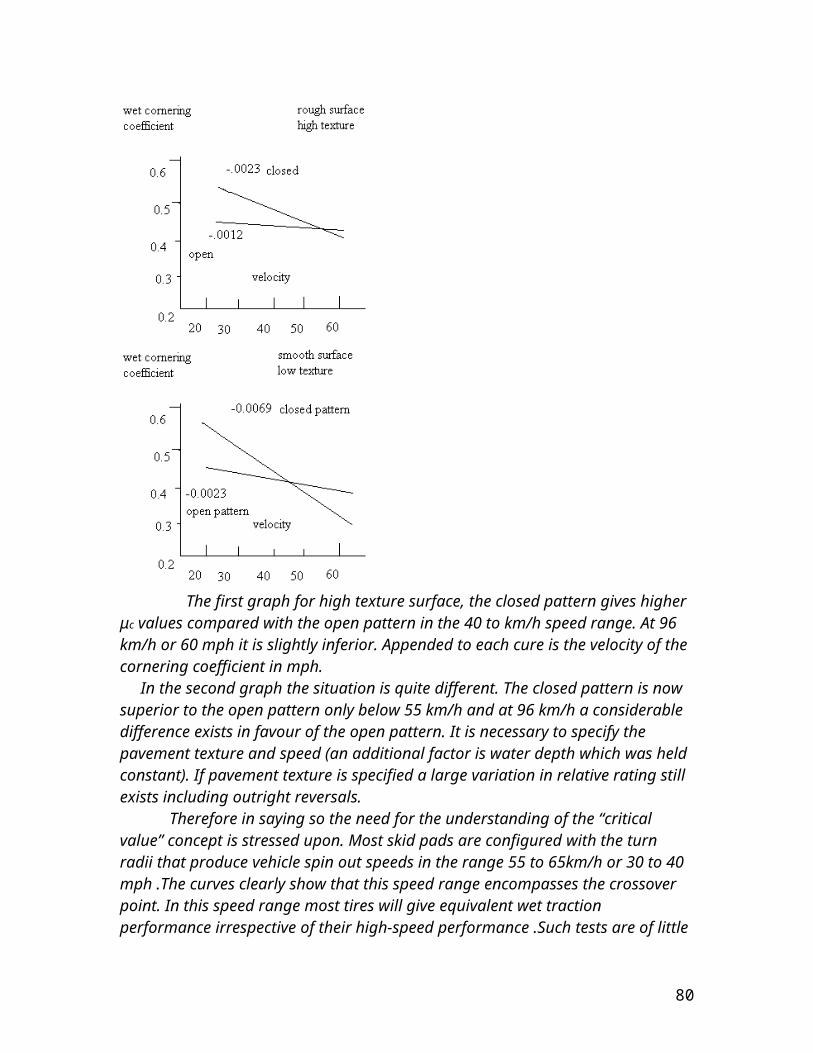
equipped with a gear system. They have an inherent trait of high torque. Same is the case here. Their rpm is 150 for an input of 24 volts.
ELECTRICAL CIRCUIT:-
The circuit graphically depicts the intricate circuit employed. There is a charger system for the two batteries based on a transformer shown on the right of the picture. The working of relays has been discussed previously and so of the ICs.
80
CALCULATIONS
For the sinkage of tires we have the formula as follows:-
z o=((pi+pc)/(kc/b+kφ))^1/n
for the motion resistance we have Rc=(b(pi+pc)^(n+1)/n)/(n+1)( kc/b+kφ)^1/nfor the compaction resistance we have Rcr=b(kφ)(zo^n+1)/(n+1)the slip velocity is given by vj=rω(1-(1-i)cosθ where θ is used for φ tabulated for soils earlier and i is the slip of the track usually taken to be about 0.1-0.26 at this scale and these types of terrains
the weight of the vehicle amounts to about 80 kg or 176.4 lbm
there fore for the clayey soil:-zo=sinkage=((25+0.39)/(4+16))^1/0.5=((25.39)/20)^2=1.611 in
The motion resistance Rc amounts to =3(25+0.39)³/(1.5)(12/3+16)² =81.84lbf
The compaction resistance Rcr=3(16)(1.611^1.5)/1.5 65.43lbf
The slip velocity will amount to =4.875(.041)(1-(1-0.221)cos13) =0.2(0.241) =0.0482m/s or 0.161ft/s
for the muskeg:- zo=sinkage=((25+0.39)/(7/3+14)))^1.43 =((25.39)^1.43)/(16.33)^1.43 =102.02/54.27 =1.8798 in
The motion resistance Rc amounts to=( 3(25+0.39)^2.43)/(1.7)(7/3+14)^1.43 =(3(25.39^2.43))/(1.7)(16.33^1.43) = 7770.55/92.26 =84.22lbf
The compaction resistance Rcr=(3)(14)(1.8798^1.7)/(1.7) =122.812/1.7 =72.24lbf
The slip velocity amount to =4.875(0.041)(1-(1-0.23)cos10
81
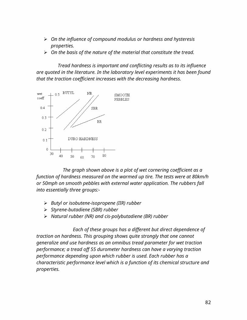
=0.159ft/s
Dry Sand:- zo= sinkage amounts to ((25+0.39)/(0.1/3+3.9))^1/1.1 =((25.39)/3.933)^0.9 =5.4 in
The motion resistance amounts to Rc=(3(25+0.39)^1.90)/((1.1+1)(0.1/3+3.9)^0.9) =(3(25.39)^1.90)/((2.1)(3.43)) =1399.52/7.203 =194.3lbfThe compaction resistance comes to be Rcr=3(3.9)(5.4^2.1)/2.1 =403.84/2.1 =192.31lbf
The slip velocity amounts to i=0.25 =4.875(0.041)(1-(1-0.25)cos28) =0.23ft/s
Heavy Soil:-
For this type of soil the sinkage amounts to zo=((25+0.39)/(45/3+140))^1/0.13 =((25.39)/(15+140))^7.69 =((25.39)/(155))^7.69 =9.0825×10^-7in
The motion resistance amounts to Rc=(3(25+0.39)^1.13/0.13)/(1.13)(45/3+140)^7.69 =3(1.608×10^12)/(7.88×10^16) =61.22μlbf
The compaction resistance amounts to Rcr=((3)(140)(zo)^1.13)/1.13 =55.33μlbf
The slip velocity amounts to be for i=.2 as follows =4.875(0.041)(1-(1-0.2)cos34) =0.22ft/s
Determination of the metacentric height:-
P=196.2 Nx=4in=0.1mθ=15=0.262 radiansW=65(9.81)=637.65N
GM=metacentre height from the centroid of the body=Px/Wθ
82
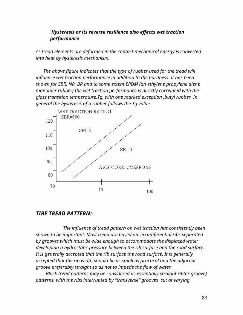
=(196.2×0.1)/(635.65×0.262) =0.12 m =4.72in
The lift and drag on he tilted front end of the vehicle in water:-
Since the above drawn figure shows we have for this case:-
dFx=-pcos315dA+τwcos315dA
dFy=psin315dA+τwsin315dA
therefore by integrating on both sides we get:-
D=∫dFx=-∫pcos315dA+∫ τwcos315dA
And L=∫dFy=∫psin315dA+∫ τwsin315dA
We know for a fact that part of the vehicle that submerges equals about 8.4 in above the lower base plate of the vehicle or in other words 0.2134m. The breadth of the facing plate that is inclined at 45 degrees to the incoming stream of velocity is 20 in or 0.51m. The length of the plate in water equals 11.88in or 0.31m.
Therefore D=- ∫(0→0.99)pcos315dA+∫(0→0.99) τwcos315dA
=-0.876∫[1-y²/4]dy+0.0015∫[x^-1/2]dx
=-0.876[y-y³/12](0→0.70)+0.0030[x^1/2](0→0.70) =-0.8761[0.7-0.03]+0.0030[0.84] =-0.8761[0.67]+0.0030[0.84]
83
=-0.59+0.00252
=-0.587lbf
For the lift part of the acting force we have
L=∫(0→0.99)psin315dA+∫(0→0.99) τwsin315dA
=-0.876∫[1-y²/4]dy-0.0015∫[x^-1/2]dx
=-0.876[y-y³/12](0→0.70)-0.0030[x^1/2](0→0.70) =-0.8761[0.7-0.03]-0.0030[0.84]
=-0.8761[0.67]-0.0030[0.84] =-0.59-0.00252
=-0.587lbf
The total force therefore acting on the slanted edge placed at an angle of 45 degrees is √((-0.587)²+ (-0.587)²)
=0.83lbf
The lift and drag acting on the fins:-
As stated earlier the fins are made up 4 metal plates that are basically perpendicular to each other and therefore it has to be assumed that a couple of these plates is perpendicular to incoming stream of water and another couple is parallel to the incoming stream of water.
The fins are made up of plates that are 2in in width and 4in in length.
84
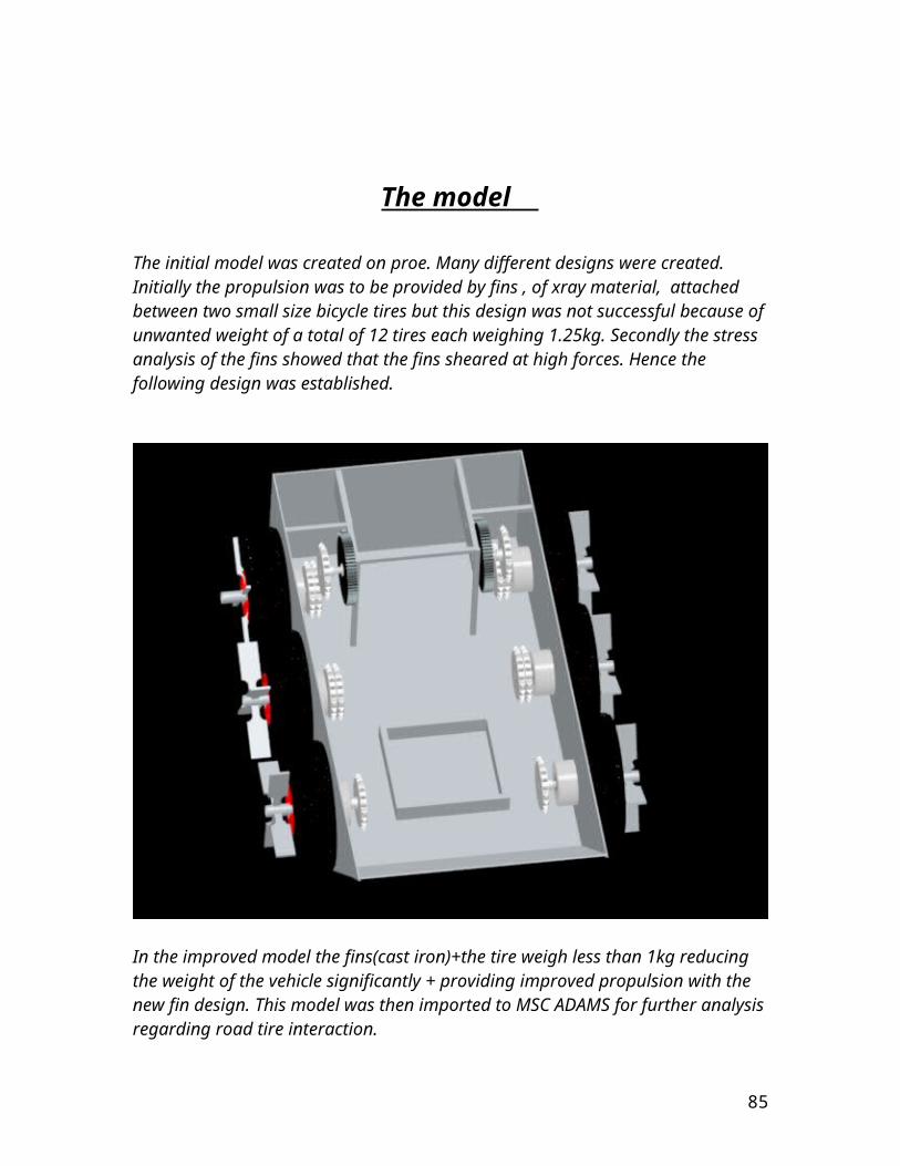
Therefore two couples are joined together at 90 degrees and they each are 2in wide and 4in in length.
And in this case the equations for the lift and drag become:-
D=∫dFx=∫pcosθdA+∫ τwsinθdA
And L=∫dFy=-∫psinθdA+∫ τwcosθdA
For the position in which a plate is parallel to the flow and therefore the angle is 90 for the top surface and 270 for the bottom surface. Therefore at these angles
L=-∫(top)pdA+∫(bottom)pdA =0And D=∫(top) τwdA+∫ (bottom)τwdA =2∫ τwdA
D=2∫(0→0.33)( (1.24E-3)/√x)(0.166)dx
=4.73E-4lbf =0.000473lbf
For the angle in which the fin is perpendicular then the effective length is 8in or 0.6666ft
The effective angle is 0 and 180.
L=∫(front) τwdA-∫(back) τwdA =0
D=∫(front) pdA-∫(back)pdA
Again there is no lift because the pressure forces act parallel to the upstream flow (in the direction of D not L) and the shear stress is symmetrical about the centre of the plate. With the given relatively large pressure on the front of the plate (the centre of the plate is a stagnation point) and the negative pressure (less than the upstream pressure) on the back of the plate, we obtain the following drag.
D=∫(-0.33→0.33)[0.74(1-y²/4)-(-0.893)](0.166)dy
=0.123(-0.33→0.33)[y-y³/12]+ 0.15(-0.33→0.33)[y] =0.123[0.66+0.024]+0.15[0.66] =0.084+0.099 =0.183lbf
85
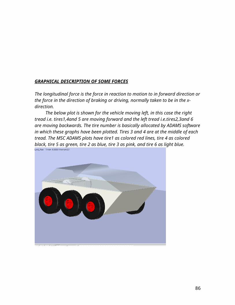
Clearly there are two mechanisms responsible for the drag. On the ultimately stream lined body (a zero thickness flat plate parallel to the flow) the drag is entirely due to the shear stress at the surface and, in the case considered above is relatively small. For the ultimately blunted body (a flat plate normal to the upstream flow) the drag is entirely due to the pressure difference between the front and the back portions of the object and in this above considered case, is relatively large. If the flat plates were oriented at arbitrary angle relative to the upstream flow, there would be both a lift and a drag, each of which would be dependent on both the shear stress and the pressure. Both the pressure and shear stress distributions would be different for the top and the bottom surface.
Determination of the centroid of the body with respect to x and y axes:-
We first divide the body into 5 area sections i.e. A1,A2,A31,A32, and A33.
Now we must know that the largest area section under consideration here is A1 and the smallest being the area section A2 which is the triangular area section and the intermediate three area sections are the area sections A31,A32, and A33 these area sections equal and basically are the area sections of the tires in two dimensional coordinates i.e. x and y. Now we take the centroid coordinate local system at the largest area section.
Now ¯x1 =0, ¯y1=0
¯x31=-0.274m, ¯y31=-1.5in=-0.0381m
¯x32=-0m, ¯y32=-1.5in=-0.0381m
¯x33=0.274m, ¯y33=-1.5in=-0.0381m
¯x2= 0.49m, ¯y2=1.6in=0.042mA1=0.206m², A2=0.0323m²,A3=0.0486m²
ΣA=0.312m²
¯x=((-.274)(0.0486)+0+(.274)(0.0486)+(0.49)(0.0323))/0.312
=0.051m =2inOr from vertex end it is 18in
¯y=((-5.55E-3)+(1.4E-3))/0.312
86
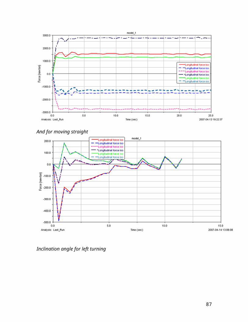
=-0.013m =-0.5in
Or 4.5in at vertex coordinates
Therefore the coordinates of the centroid are (18,4.5) However it should be kept in mind that these coordinated of the centroid are not acquired by considering the internal weights of the body i.e. of the framework and motors and batteries. Considering those elements would have to mean that the centroid would shift its coordinates When we consider the top of the body in the z-x plane we notice that there is symmetry along the z-axis.This therefore means that ¯z=10in (if we place the coordinate system at the vertex of the body, i.e. at the mid of the breadth of vehicle)
The centroid of the body is considered only for the lower body because the top has a an extremely low weight almost negligible compared to the lower body of the vehicle. And therefore due to the low weight of the top there isn’t much contribution of the top as far as the mechanics of the body are concerned.
Determination of the angle of inclination before the tires slide:-
The x and y axes are taken as slanted equal to the angle of inclination of the ramp.We know that the coefficient of friction for the tire on smooth concrete comes up to be 0.6.
Therefore FB=0.6NB where FB is the friction force and NB is the normal reaction force. Therefore The summation of forces in the inclined x-direction are:- 176.32sinθ- FB=0The summation of forces in the inclined y-direction are:-
NB-176.32cosθ=0
Where 176.32 is the weight of body in lbs
176.32sinθ= FB
176.32sinθ=0.6 NB
NB=293.9sinθTherefore 293.9sinθ-176.32cosθ=0Tan θ =0.59θ=30.99 degrees.NB=151.33lbfFB=90.8lbf
87

At the above given angle of inclination of the ramp the tires of the vehicle are locked on the ramp due to the weight and the coefficient of friction and the number of tires that lock on the concrete ramp. In this case the angle tells of the maximum tilt that can be tolerated by the tires before they start sliding in the down position. The maximum angle of tilt that has been stated above is the angle at which the vehicle can resist sliding.
Buoyancy analysis of the vehicle:-
The buoyant force acting on the vehicle is equal to the weight of the body. The more sinking of the vehicle, the more the upward thrust of the water.
When the vehicle is floating fully constructed and in an unloaded condition. We must consider that the length of the vehicle is 42in or 1.07m, and the breadth of the vehicle is 20in or 0.51m, and the present sinking in the water bodies is 8.4in or 0.2m.
Therefore The weight of the vehicle=Upthrust on the immersed volume Weight of the vehicle=weight of the fluid displaced W=ρgBlD
Where B is the width, l is length, and D is the draught or sinking W=1025(9.81)(0.11414)(0.51) =585N However there are six tires with fins that are providing the buoyancy to the vehicle =52.97NTherefore the total net reaction of water upthrust comes to be =638N Therefore the weight of the vehicle body is=65kg
The total weight allowance comes up to be
88
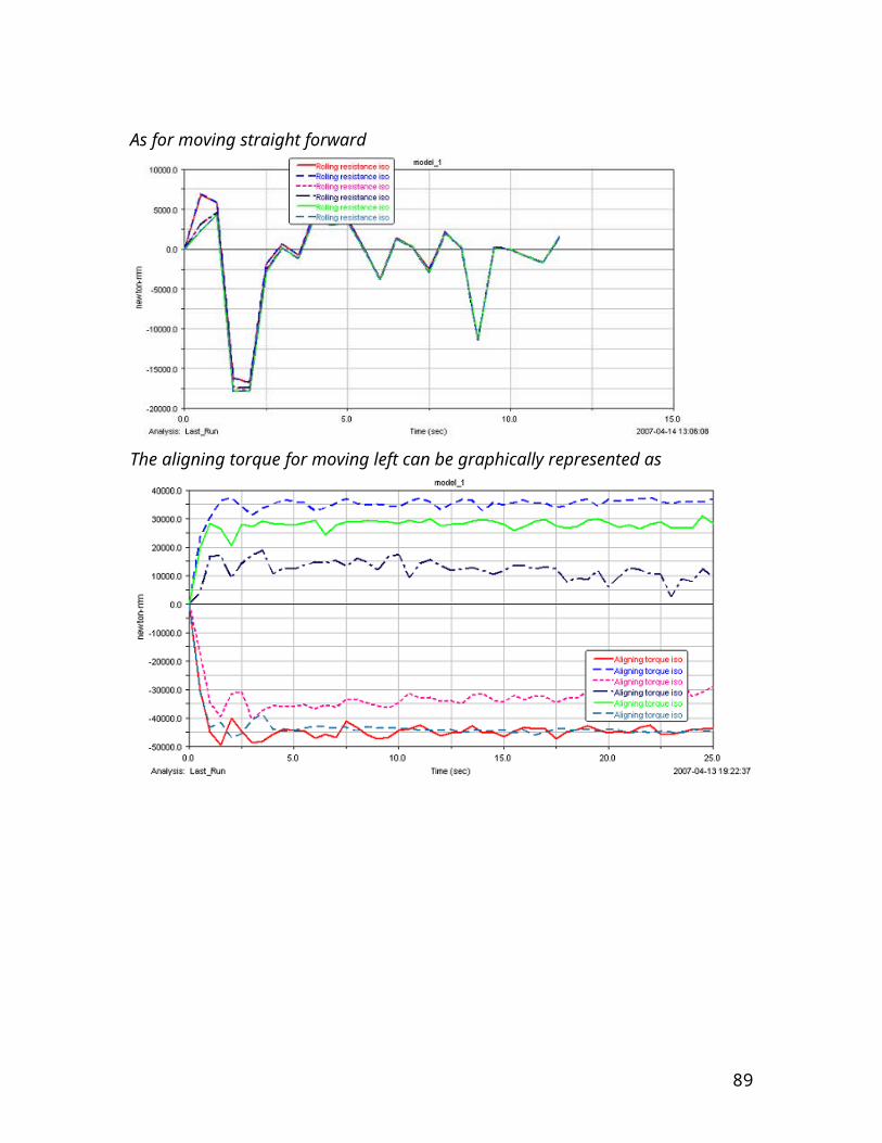
B=1025(0.1213)(9.81) =1219.70N-585N-52.97N =581.7N =59kg weight can be placed on it has sunk full lower torso and axial fans placed for propulsion.
A BRIEF OVERVIEW OF THE VEHICLE DESIGN CHOICES
At this point in the study of the report, many questions arise as to the logic and reasoning behind the choices of the material employment and design features that have been associated to the vehicle.To address the choice of material we must first adhere to the primary theme of the project.
SELECTION OF THE MATERIAL:- The material that has been used is primarily mild steel and although we had many option at hand but the choice of the employment of mild steel prevailed. It is used in the fabrication of the main body of the vehicle, it is employed in the fabrication of the seal from raw metal steel plates and the reason being that there was obviously a large bore of the seal required and since the water proofing was required on both ends of the seal. Without double ended water proofing there always was a chance of the water leakage. The inner water proofing washers are made up of rubber and are available commercially but having described the amount and type of material used in the fabrication of the water seal, naturally the weight of the total seal increased. The seals have been fabricated and machined from steel billets. Having said this it should be kept in mind that with increased weight we need increased strength and therefore mild steel was our answer. The entire framework of the vehicle body and the electronics holdings have all been made up of mild steel and even the transmission shafts that take the drive from the sprocket and chain based drive system to the wheel based tread sets. The top of the vehicle has been fabricated from fiber glass of 1xply thickness. And is partially transparent with a rough outer texture that has been painted.
REASONING:-
The logic behind the employment of mild steel over other metals are as follows:- Carbon steel, also called plain carbon steel, is a metal alloy, a
combination of two elements, iron and carbon, where other elements are present in quantities too small to affect the properties.
Types of carbon steel Medium carbon steel: approximately 0.29% to 0.54% carbon content,
High carbon steel: approximately 0.55% to 0.95% carbon content
89
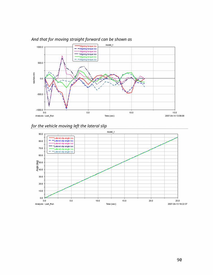
Very high carbon steel: approximately 0.96% to 2.1% carbon content And in our the most important of all:- Mild (low carbon) steel: approximately 0.05% to 0.26% carbon content With 0.4 percent manganese content.
Mild steel has a relatively low tensile strength of 500MPa It is cheap and malleable. Surface hardness can be increased through carburizing although this is
just a general property not all taken into consideration for the employment of steel in this project since carburizing itself was out of the question and the surface hardness played little role in the project.
Mild steel is the most common form of steel as its price is relatively low while it provides material properties that are acceptable for many applications.
Mild steel has a low carbon content (up to 0.3%) and is therefore neither extremely brittle nor ductile.
It is also often used where large amounts of steel need to be formed, for example as structural steel.
Density of this metal is 7,861.093 kg/m³. It has a Young's modulus of 2.1x10¹¹Pa. Although light weight was imperative and keeping that in mind alone
meant the employment of aluminium but as aluminium was tried for this task and it sagged and buckled under the weight of the shafts and the seals and the increasing weight of the electrical input.
The working of steel is easy and abundantly done by many metal workers in the country however the working of aluminium is not easy it requires a special type of welding and moreover it requires riveting and moreover aluminium working is scarcely found among the metal worker community.
The cost of steel sheet is much less as compared to the cost of aluminium sheets.
The question may arise as to why there was no employment of aluminium in the fabrication of seals? Well, despite its inherent water proof properties, we had to consider the cost effect of the employment of materials.
The material of the sprockets and the chains was not of our choice for it was the most common and industrially available fabricated set and therefore customization of the sets with the drive mechanism could not be achieved, thus despite many improvements it still results in a minor slipping of the chain from the teeth of the sprocket and causes some speed lag and minor noise production.
90
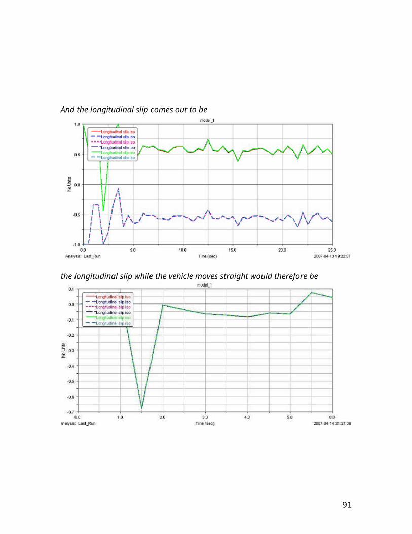
References
Theory of terra mechanics
Tire and pavement interaction by Monroe
Tire and vehicle dynamics by Hans.B.Pacejka
Electromechanical machine basics
ADAMS tutorials
Fundamental of Fluid mechanics by Munson
Mechanics of materials (text book)
Avenger 6x6 (internet)
91
Related Documents