M/s Scania Steels and Powers Ltd. PROJECT FEASIBILITY REPORT PROPOSED EXPANSION PROJECT OF THE EXISTING INTEGRATED STEEL PLANT OF M/S SCANIA STEELS & POWERS LTD. At Village: Punjipatra, Tehsil: Tamnar, District: Raigarh, Chhattisgarh.

Welcome message from author
This document is posted to help you gain knowledge. Please leave a comment to let me know what you think about it! Share it to your friends and learn new things together.
Transcript

M/s Scania Steels and Powers Ltd.
PROJECT FEASIBILITYREPORT
PROPOSED EXPANSION PROJECT OF THE EXISTING INTEGRATEDSTEEL PLANT OF M/S SCANIA STEELS & POWERS LTD.
At
Village: Punjipatra, Tehsil: Tamnar, District: Raigarh,Chhattisgarh.

Contents
Section Description
1.0 Executive Summary
2.0 Introduction of the Project/ Background Information
3.0 Project Description
4.0 Site Analysis
5.0 Planning Brief
6.0 Proposed Infrastructure
7.0 Rehabilitation and Resettlement (R&R) Plan
8.0 Project Schedule and Cost Estimates
9.0 Analysis of Proposal

Pre-feasibility Report
M/s. SCANIA STEELSAND POWERS LTD.
Proposed expansion project of the existing integrated steel plant of M/s ScaniaSteels & Powers Ltd. in its own premises at Village: Punjipatra, Tehsil Tamnar,
District Raigarh in Chhattisgarh.
1.0 EXECUTIVE SUMMARYM/s Scania Steels and Powers Ltd. (formerly known as Sidhi Vinayak Sponge Iron Pvt.Ltd.) was incorporated on 25th August, 1995. The company has its registered office at 22
km Stone, Gharghoda Road, Punjipatra, Raigarh 496011, Chhattisgarh and is promoted
by Sri Sanjay Gadodia (Director). The company is operating one unit at Village:
Punjipatra, Tehsil Tamnar, District Raigarh in Chhattisgarh with existing facilities of
4x100 TPD DRI Kilns. Besides, 1 x 6 T + 1 x 8 T IFs have been implemented but are not
under operation, 2x15 T Induction Furnaces have not yet been implemented and a 8
MW WHRB based Captive Power Plant is under implementation stage, for which the
environmental clearance has already been granted by MoEF&CC.
Encouraged by the anticipating better future market, the company is planning to expand
its existing integrated steel plant by installing some new units on the available land of its
existing plant premises as well as on some additional land, adjacent to its existing plant
premises.
Salient features of the proposed project are given in Table-1.0.
Table - 1.0 : Salient Features of the Proposed Project
SL.NO.
PARTICULARS DETAILS
1. Nature of the Project Proposed expansion project of the existing integrated steel plant
2. Size of the Project Proposed Units Capacity
Sponge Iron Plant (DRI) 2X350 TPD(Capacity- 2,31,000 TPA)
Steel Melting Shop (SMS) 3X20 T with 6/11 CCM(Capacity- 1,85,000 TPA)
Captive power plant 18 MW (WHRB/)+ 6 MW (AFBC)(Total: 24 MW)
Iron Ore Beneficiation Plant 1 x 2.67 MTPA(Capacity- 26,70,000 TPA)
Pelletization Plant 2X0.8 MTPA(Capacity- 16,00,000 TPA) with dualfiring system for 0.8 MTPA Each as:
1.Gasifier (50%) - 4X6000m3/hcapacity (3 in operation and 1 asstandby)
2.Pulverized Coal Injection (40%) -
Pre-feasibility Report
M/s. SCANIA STEELSAND POWERS LTD.
Proposed expansion project of the existing integrated steel plant of M/s ScaniaSteels & Powers Ltd. in its own premises at Village: Punjipatra, Tehsil Tamnar,
District Raigarh in Chhattisgarh.
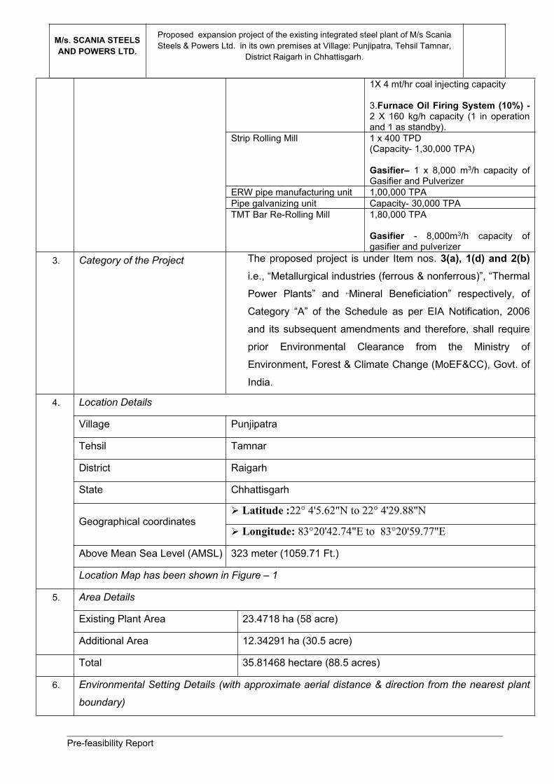
1X 4 mt/hr coal injecting capacity
3.Furnace Oil Firing System (10%) -2 X 160 kg/h capacity (1 in operationand 1 as standby).
Strip Rolling Mill 1 x 400 TPD(Capacity- 1,30,000 TPA)
Gasifier– 1 x 8,000 m3/h capacity ofGasifier and Pulverizer
ERW pipe manufacturing unit 1,00,000 TPAPipe galvanizing unit Capacity- 30,000 TPATMT Bar Re-Rolling Mill 1,80,000 TPA
Gasifier - 8,000m3/h capacity ofgasifier and pulverizer
3. Category of the Project The proposed project is under Item nos. 3(a), 1(d) and 2(b)i.e., “Metallurgical industries (ferrous & nonferrous)”, “Thermal
Power Plants” and “Mineral Beneficiation” respectively, of
Category “A” of the Schedule as per EIA Notification, 2006
and its subsequent amendments and therefore, shall require
prior Environmental Clearance from the Ministry of
Environment, Forest & Climate Change (MoEF&CC), Govt. of
India.
4. Location Details
Village Punjipatra
Tehsil Tamnar
District Raigarh
State Chhattisgarh
Geographical coordinates Latitude :22° 4'5.62"N to 22° 4'29.88"N
Longitude: 83°20'42.74"E to 83°20'59.77"E
Above Mean Sea Level (AMSL) 323 meter (1059.71 Ft.)
Location Map has been shown in Figure – 1
5. Area Details
Existing Plant Area 23.4718 ha (58 acre)
Additional Area 12.34291 ha (30.5 acre)
Total 35.81468 hectare (88.5 acres)
6. Environmental Setting Details (with approximate aerial distance & direction from the nearest plant
boundary)

Pre-feasibility Report
M/s. SCANIA STEELSAND POWERS LTD.
Proposed expansion project of the existing integrated steel plant of M/s ScaniaSteels & Powers Ltd. in its own premises at Village: Punjipatra, Tehsil Tamnar,
District Raigarh in Chhattisgarh.
a. Nearest Town Raigarh is located at 20 km South from the project site.
b. Nearest City Bilaspur is located at 125 km East from the project site.
c. Nearest National / State Highway NH-200 (Raipur, Bilaspur, Sarangarh, Raigarh, Deogarh,
Talcher and Chandikhol linking National Highway) is passing
through Raigarh about 19 kms distance (aerial distance) in
south direction from the project site.
d. Nearest Railway station Bhupdeopur Railway Station, which is located at about 14.2 km
distance (aerially) in south-west direction from the project site.
The distance of Raigarh Railway station from the project site is
about 20.5 km (aerial), located at ‘SSE’ direction w.r.t. the
project site.
e. Nearest Airport The nearest Airport is Raipur Airport in Chhattisgarh known as
Swami Vivekanand International Airport, which is located at
about 250 km (aerial distance) in west direction from the
project site.
f. National Parks, Wildlife
Sanctuaries, Biosphere
Reserves, within 10 km radius
N.A.
g. Reserved Forests (RF) /
Protected Forests (PF) within 10
km radius
Urdhana RF, Taraimal RF, Kharidungari RF, Maghat RF,
Pajhar RF, Rabo RF, Lakha RF, Barakachar RF, Dungapani
RF, Punjipatra RF, Suhai RF, and Samaruma RF are existing
within 10 km radius study area around the Project site.
h. Water Bodies (within 10 km
radius)
The important river in the study area is Kelo River, which flows
at a distance of 6.3 kms in ESE direction from the project site.
This river is a main tributary of River Mahanadi, which is the
major important river in Chhattisgarh. Kurket River, which is
another important river in the study area is flowing about 7.6
kms in WNW direction from the project site. The Rabo dam,
which is situated on the way of the Kurket River is located
about 7 kms distance in west direction from the project site.
i. Seismic Zone Seismic Zone – II
7. Cost Details
Total Cost of the Project Rs. 641.00 Crores.
8. Basic Requirements for the project

Pre-feasibility Report
M/s. SCANIA STEELSAND POWERS LTD.
Proposed expansion project of the existing integrated steel plant of M/s ScaniaSteels & Powers Ltd. in its own premises at Village: Punjipatra, Tehsil Tamnar,
District Raigarh in Chhattisgarh.
Water Requirement Quantity Source
Existing : 514 KLD
Proposed: 2464 KLD
Total : 2,978 KLD
Ground Water
Power Requirement Power requirement for the existing project:15 MW
Power requirement for the proposed project: 41 MW
Total Power requirement after the expansion of the project: 56
MW
The power will be sourced from 32 MW capacity captive power
plant & balance from the state grid.
Manpower Requirement Manpower requirement for the proposed project
ParticularsConstruction
PhaseOperationPhase
Regular 25 471
Contractual 270 220
TOTAL 295 691

Pre-feasibility Report
M/s. SCANIA STEELSAND POWERS LTD.
Proposed expansion project of the existing integrated steel plant of M/s ScaniaSteels & Powers Ltd. in its own premises at Village: Punjipatra, Tehsil Tamnar,
District Raigarh in Chhattisgarh.
2.0 INTRODUCTION OF THE PROJECT/ BACKGROUNDINFORMATION
(i) Identification of project and project proponent
Project Details
M/s Scania Steels and Powers Ltd. (formerly known as Sidhi Vinayak Sponge Iron Pvt.Ltd.) was incorporated on 25th August, 1995. The company has its registered office at 22
km Stone, Gharghoda Road, Punjipatra, Raigarh 496011, Chhattisgarh and is promoted
by Sri Sanjay Gadodia (The Director). The company is operating one unit at Village:
Punjipatra, Tehsil Tamnar, District Raigarh in Chhattisgarh with existing facilities of
4x100 TPD DRI Kilns. Besides, 1 x 6 T + 1 x 8 T IFs have been implemented but are not
under operation, 2x15 T Induction Furnaces have not yet been implemented and a 8
MW WHRB based Captive Power Plant is under implementation, for which the
environmental clearance has already been granted by MoEF&CC.
Encouraged by the anticipating better future market, the company is planning to expand
its existing integrated steel plant by installing some new units on the available land of its
existing plant premises as well as on some additional land, adjacent to its existing plant
premises.
The overall project scenario is presented in Table-2.0.
Pre-feasibility Report
M/s. SCANIA STEELSAND POWERS LTD.
Proposed expansion project of the existing integrated steel plant of M/s ScaniaSteels & Powers Ltd. in its own premises at Village: Punjipatra, Tehsil Tamnar,
District Raigarh in Chhattisgarh.
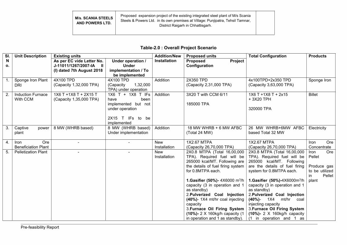
Table-2.0 : Overall Project ScenarioSl.No.
Unit Description Existing units Addition/NewInstallation
Proposed units Total Configuration ProductsAs per EC vide Letter No.J-11011/1267/2007-IA II(I) dated 7th August 2018
Under operation /Under
implementation / Tobe implemented
Proposed ProjectConfiguration
1. Sponge Iron PlantDRI
4X100 TPD(Capacity 1,32,000 TPA)
4X100 TPD(Capacity 1,32,000TPA) under operation
Addition 2X350 TPD(Capacity 2,31,000 TPA)
4x100TPD+2x350 TPD(Capacity 3,63,000 TPA)
Sponge Iron
2. Induction FurnaceWith CCM
1X6 T +1X8 T + 2X15 T(Capacity 1,35,000 TPA)
1X6 T + 1X8 T IFshave beenimplemented but notunder operation
2X15 T IFs to beimplemented
Addition 3X20 T with CCM 6/11
185000 TPA
1X6 T +1X8 T + 2x15+ 3X20 TPH
320000 TPA
Billet
3. Captive powerplant
8 MW (WHRB based) 8 MW (WHRB based)Under implementation
Addition 18 MW WHRB + 6 MW AFBC(Total 24 MW)
26 MW WHRB+6MW AFBCbased Total 32 MW
Electricity
4. Iron OreBeneficiation Plant
- - NewInstallation
1X2.67 MTPA(Capacity 26,70,000 TPA)
1X2.67 MTPA(Capacity 26,70,000 TPA)
Iron OreConcentrate
5. Pelletization Plant - - NewInstallation
2X0.8 MTPA (Total 16,00,000TPA). Required fuel will be265000 kcal/MT. Following arethe details of fuel firing systemfor 0.8MTPA each.
1.Gasifier (50%)- 4X6000 m3/hcapacity (3 in operation and 1as standby)2.Pulverized Coal Injection(40%)- 1X4 mt/hr coal injectingcapacity3.Furnace Oil Firing System(10%)- 2 X 160kg/h capacity (1in operation and 1 as standby).
2X0.8 MTPA (Total 16,00,000TPA). Required fuel will be265000 kcal/MT. Followingare the details of fuel firingsystem for 0.8MTPA each.
1.Gasifier (50%)-4X6000m3/hcapacity (3 in operation and 1as standby)2.Pulverized Coal Injection(40%)- 1X4 mt/hr coalinjecting capacity3.Furnace Oil Firing System(10%)- 2 X 160kg/h capacity(1 in operation and 1 as
Iron OrePellet
Produce gasto be utilizedin Pelletplant
Pre-feasibility Report
M/s. SCANIA STEELSAND POWERS LTD.
Proposed expansion project of the existing integrated steel plant of M/s ScaniaSteels & Powers Ltd. in its own premises at Village: Punjipatra, Tehsil Tamnar,
District Raigarh in Chhattisgarh.
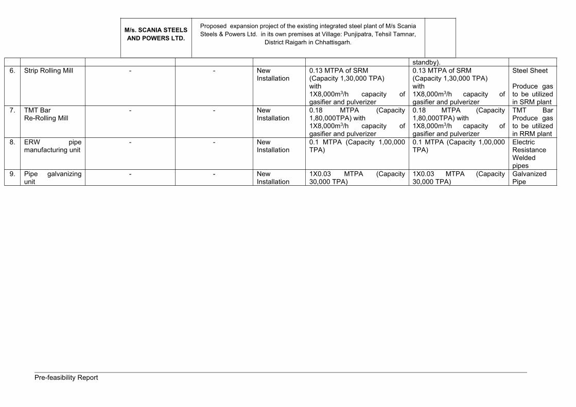
standby).6. Strip Rolling Mill - - New
Installation0.13 MTPA of SRM(Capacity 1,30,000 TPA)with1X8,000m3/h capacity ofgasifier and pulverizer
0.13 MTPA of SRM(Capacity 1,30,000 TPA)with1X8,000m3/h capacity ofgasifier and pulverizer
Steel Sheet
Produce gasto be utilizedin SRM plant
7. TMT BarRe-Rolling Mill
- - NewInstallation
0.18 MTPA (Capacity1,80,000TPA) with1X8,000m3/h capacity ofgasifier and pulverizer
0.18 MTPA (Capacity1,80,000TPA) with1X8,000m3/h capacity ofgasifier and pulverizer
TMT BarProduce gasto be utilizedin RRM plant
8. ERW pipemanufacturing unit
- - NewInstallation
0.1 MTPA (Capacity 1,00,000TPA)
0.1 MTPA (Capacity 1,00,000TPA)
ElectricResistanceWeldedpipes
9. Pipe galvanizingunit
- - NewInstallation
1X0.03 MTPA (Capacity30,000 TPA)
1X0.03 MTPA (Capacity30,000 TPA)
GalvanizedPipe

Pre-feasibility Report
M/s. SCANIA STEELSAND POWERS LTD.
Proposed expansion project of the existing integrated steel plant of M/s ScaniaSteels & Powers Ltd. in its own premises at Village: Punjipatra, Tehsil Tamnar,
District Raigarh in Chhattisgarh.
Project Proponent
M/s Scania Steels & Power Limited (SSPL) (formerly known as Sidhi Vinayak Sponge
Iron Pvt. Ltd.) was incorporated in the year 1995, having its registered office at 22 km
Stone, Gharghoda Road, Punjipatra, Raigarh 496011, Chhattisgarh.
(ii) Brief description of nature of the project
M/s Scania Steels and Powers Ltd. (formerly known as Sidhi Vinayak Sponge Iron Pvt.Ltd.) was incorporated on 25th August, 1995. The company has its registered office at 22
km Stone, Gharghoda Road, Punjipatra, Raigarh 496011, Chhattisgarh and is promoted
by Sri Sanjay Gadodia (The Director). The company is operating one unit at Village:
Punjipatra, Tehsil Tamnar, District Raigarh in Chhattisgarh with existing facilities of
4x100 TPD DRI Kilns. Besides, 1 x 6 T + 1 x 8 T IFs have been implemented but not
under operation, 2x15 T Induction Furnaces have not yet been implemented and a 8
MW WHRB based Captive Power Plant is under implementation, for which the
environmental clearance has already been granted by MoEF&CC.
Influenced by the increase in the demand of the steel made products globally, the
company has decided to expand its existing units by installing different new units as
mentioned in Table-2. A brief description of proposed project has been mentioned below:
In the overall project after expansion, the iron ores will pass through several processes
such as Beneficiation (New installation of 26,70,000 TPA capacity) and pelletization
(New installation of 16,00,000 TPA) to concentrate the iron content in the ores (>65%) &
pellet formation respectively, followed by sponge iron manufacturing in DRI unit (4X100
TPD + 2X350 TPD) which ultimately will be melted in Steel melting shop with matching
LRF & CCM (1X6T+1X8T+2X15T + 3X20T capacity). In steel melting shop, hot liquid
steel will be converted to hot Billets (3,20,000 TPA). The Billets thus formed will pass
through strip rolling mill (1,30,000 TPA capacity to manufacture steel sheet) and re-
rolling mill (1,80,000 TPA to manufacture TMT bars). A portion of the steel sheet will be
used in ERW pipe manufacturing unit (1,00,000 TPA capacity to manufacture Electric
Resistance Welded pipes). The ERW pipes will be galvanized in the proposed Pipe
galvanizing unit (30,000 TPA capacity to manufacture GI pipes). Captive power plant of
32 MW capacity will be installed, out of which 26 MW will be based on WHRB (8 MW
WHRB based CPP is under progress of implementation for which EC has already been
granted), utilizing waste heat generated from sponge iron plant and the balance 6 MW
will be based on AFBC boiler, utilizing dolochar generated from sponge iron plant.
The proposed units will be installed on the available land within the existing plant
premises of 23.4718 ha (58 acre) as well as on some additional land [12.34291 ha (30.5

Pre-feasibility Report
M/s. SCANIA STEELSAND POWERS LTD.
Proposed expansion project of the existing integrated steel plant of M/s ScaniaSteels & Powers Ltd. in its own premises at Village: Punjipatra, Tehsil Tamnar,
District Raigarh in Chhattisgarh.
acre], adjacent to the existing plant premises, thus comprising a total land area of
35.81468 hectare (88.5 acres) at Village: Punjipatra, Tehsil Tamnar, District Raigarh in
Chhattisgarh. The additional land is vacant and industrial in nature. The land is generally
flat and does not come under flood zone.
(ii) Need for the project and its importance to the Country and Region
India was the world’s 3rd largest steel producer in the year 2017. Steel industry being a
core sector, reflects the overall economic growth in the long term period. The per capita
consumption of steel is considered as an important index of the socio-economic
development including living standards of the people in any country. All major industrial
economies are influenced by the existence of a strong steel industry. The economic
growth has been largely shaped by the strength of their steel industries in their initial
stages of development.
Post de-regulation the Indian steel industry has been registering manifold development
in the context of the buoyant economy and rising demand for steel. Rapid increase in
production has made India to become the 2nd largest producer of crude steel during the
year 2018, from its 3rd largest status in 2017. The country became the largest producer
of sponge iron in the world and the 3rd largest finished steel consumer in the world after
USA and China. In a de-regulated, liberal economic scenario like India, the role of a
government is to formulate policy guidelines to facilitate the institutional
structure/mechanism for creating a favourable environment for improving efficiency as
well as performance of the steel sector. In this connection, the Government of India has
issued the National Steel Policy 2017, which focuses on long term growth for the Indian
steel industry, both on demand and supply sides by 2030-31. The Government has also
laid down a policy to encourage domestically manufactured Iron & Steel products by
providing them with preference in Government procurement. India has set a target to
achieve 300 million tonnes of annual steel production by the year 2025-30.
The growth of the steel industry significantly contributes to economic growth of the
Nation as well as to the region as it generates employment both directly and also due to
development of downstream industries. The infrastructural and other social amenities
grow in the region leading to overall development of the region.
The proposed project of M/s. Scania Steels and Powers Ltd. will cover new units and
technologies. The above will lead to manufacture steel products at a lower cost and
more importantly in a more environment friendly way.
Pre-feasibility Report
M/s. SCANIA STEELSAND POWERS LTD.
Proposed expansion project of the existing integrated steel plant of M/s ScaniaSteels & Powers Ltd. in its own premises at Village: Punjipatra, Tehsil Tamnar,
District Raigarh in Chhattisgarh.
(iv) Demand - Supply Gap
Growing economies and their fast-paced infrastructure projects are increasing the
demand in the iron and steel industry across the country. It is a product of large and
technologically complex industries having strong forward and backward linkage in terms
of material flow and income generation. Manufacturers and suppliers are prepping up to
meet the tremendous demands of iron and steel products across the country.
Current Market Scenario
SAIL, Tata Steel, JSW Steel etc. are some of the leading steel companies in India.
Indian Steel industry showed tremendous growth after the liberalization of the sector in
the 1990s. High-grade iron ore and non-coking coal, the two main ingredients for
producing steel, are easily available in India. Moreover, a robust MSME sector with labor
availability at competitive rates and a young workforce has led to the growth of steel
industry in India.
Future Growth for Iron and Steel
As per the World Steel Association insights, demand for steel will see a slow decline in
China while India along with MENA and ASEAN countries will grow. The growth of the
countries will depend on the structural reforms in the sector and the successful
implementation of government reform policies.
Globally, technological changes and regulations are affecting the steel demand. Energy
prices and substitute materials along with environmental protection policies are affecting
the global demand. At the regional level, urbanization, government reforms and
manufacturing processes are creating an impact on the iron and steel demand.
India Vision 2030
According to the Global Steel Market outlook report, the steel demand will increase from
1537 MT in 2014 to 1992 MT in 2030. Infrastructure development in developing
economies will increase the demand for iron and steel in the years to come.
Generally, market gaps in meeting the demands for steel are managed with the import of
steel. The Indian Steel Industry is expected to flourish with the National Steel Policy
2017. As per the policy, domestic manufacturing will be given more preference. The
policy charts a growth plan for the Indian Iron and Steel industry with the demand and
supply side growth by 2030-31.
Pre-feasibility Report
M/s. SCANIA STEELSAND POWERS LTD.
Proposed expansion project of the existing integrated steel plant of M/s ScaniaSteels & Powers Ltd. in its own premises at Village: Punjipatra, Tehsil Tamnar,
District Raigarh in Chhattisgarh.
Thus, the Iron and Steel industry has a raising scope for growth and development in
India and grabbing the opportunities in this industry with due consideration of the
environmental affairs will be considered as a boon to the overall economic structure of
the country.
(v) Imports vs. Indigenous production
Imports:-
As per the monthly report of Iron & Steel, February 2020, the following import export
scenario of iron and steel in India has been derived:
On Month on Month (M-o-M) basis, exports of finished steel during February, 2020
declined by 17.8% and stood at 0.570 MT. Hike in domestic prices was one of the
main factors behind export decline. Export, however, was higher than imports by
0.169 MT during the same period.
A declining trend in imports has been observed since September 2019. Barring, the
month of January 2020, imports were contained below 0.430 MT between Nov.,
2019 to Feb., 2020. On M-o-M basis, imports at 0.401 MT declined by 16% during
February 2020. The same also declined by 31.2% over CPLY.
For cumulative period, April- February, 2020, India imported 6.39 MT finished steel
products as against 7.13 MT thereby registering 10.4% decline over CPLY.
Domestic competitive prices as compared to high landed prices of imports were the
main reasons for decline. During this period steel imports were found to be declined.
Maximum decline was observed in imports from Vietnam. During February 2020,
the maximum decline was witnessed from Japan. Korea continued to be the top
exporter to India, followed by China and Japan.
Export scenario:
As per the monthly report of Iron & Steel, February 2020, the following export scenario of
iron and steel in India has been derived:
On M-o-M basis, exports of finished steel have observed a declining trend since
October 2019. Exports at 1.019 MT were maximum during September 2019, which
reduced to almost half during February 2020.
However, India remained net exporter in steel for the seven consecutive months i.e.,
August, 2019 to February, 2020. Steel exports registered a significant growth of
34.9% during April, 2019 - February, 2020 over CPLY with trade surplus at 1.39 MT.

Pre-feasibility Report
M/s. SCANIA STEELSAND POWERS LTD.
Proposed expansion project of the existing integrated steel plant of M/s ScaniaSteels & Powers Ltd. in its own premises at Village: Punjipatra, Tehsil Tamnar,
District Raigarh in Chhattisgarh.
Steel exports to Vietnam and Taiwan witnessed an increase during April- February
2020, whereas, it declined in case of Belgium, Spain and Malaysia. Vietnam
remained top most destination of Indian steel exports by accounting nearly 29% of
total steel exports. During February 2020 nearly 60% of total exports accounted by
Vietnam, UAE and Nepal with share of 28.3%, 15.8% and 14.8% respectively.
M-o-M basis, Indian iron ore exports at 2.05 MT declined by 28% during February
2020. Iron ore exports dropped due to weak demand following Corona Virus
outbreak in China, which led falling inquiries for February 2020 shipments. Indian
iron ore exports to China at 1.71 MT, dropped by 35% in February 2020.
(vi) Export Possibility
As the demand of Iron and steel products in India is very high, at present the Scope of
Export is limited. However, In future when the production capacity of iron and steel
products will increase it my become prudent to conceive the export of its products.
(vii) Domestic / Export Markets
While the demand for steel will continue to grow in traditional sectors such as
infrastructure, construction, housing automotive, steel tubes and pipes, consumer
durable, packaging, and ground transportation, specialized steel will be increasingly
used in hi-tech engineering industries such as power generation, petrochemicals,
fertilizers etc. The new airports and railway metro projects will require a large amount of
steel. Hence, the domestic and export markets for steel sector will rise.
(viii) Employment Generation (Direct and Indirect) due to the project
M/s. Scania Steels and Powers Ltd. will employ maximum human resources from local
area. Only when skilled human resources are not available locally, the same will be
brought from outside.
The proposed project will generate both direct & indirect employment. Approx. 295
persons will be provided employment during construction phase of the proposed project,
which is of temporary in nature. However, during commercial operation, about 470
person will be employed directly. Skilled and unskilled people on daily average will be
employed. The Company will give preference to the local people during construction and
operation phases of the project, depending upon the skill, job requirement and capability.
Table-3.0 gives a break-up of the manpower requirement.
Pre-feasibility Report
M/s. SCANIA STEELSAND POWERS LTD.
Proposed expansion project of the existing integrated steel plant of M/s ScaniaSteels & Powers Ltd. in its own premises at Village: Punjipatra, Tehsil Tamnar,
District Raigarh in Chhattisgarh.
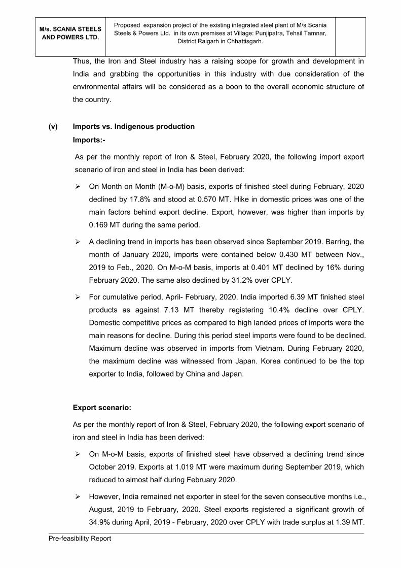
Table-3.0: Manpower Requirement for the proposed project
ParticularsConstruction
PhaseOperationPhase
Regular 25 471
Contractual 270 220
TOTAL 295 691
3.0 PROJECT DESCRIPTION(i) Type of project including interlinked and interdependent projects, if any:
The project is interdependent in nature.
M/s. Scania Steels and Powers Limited proposes to expand its existing steel plant by
installing some new units on the available land of its existing plant premises as well as
on some additional land adjacent to its existing plant premises at Village: Punjipatra,
Tehsil Tamnar, District Raigarh in Chhattisgarh.
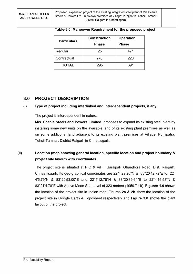
(ii) Location (map showing general location, specific location and project boundary &project site layout) with coordinates
The project site is situated at P.O & Vill.: Saraipali, Gharghora Road, Dist. Raigarh,
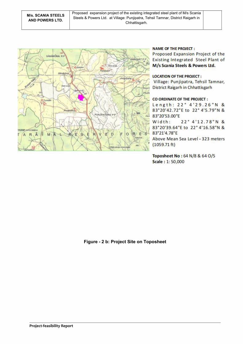
Chhasttisgarh. Its geo-graphical coordinates are 22°4'29.26"N & 83°20'42.72"E to 22°
4'5.79"N & 83°20'53.00"E and 22°4'12.78"N & 83°20'39.64"E to 22°4'16.58"N &
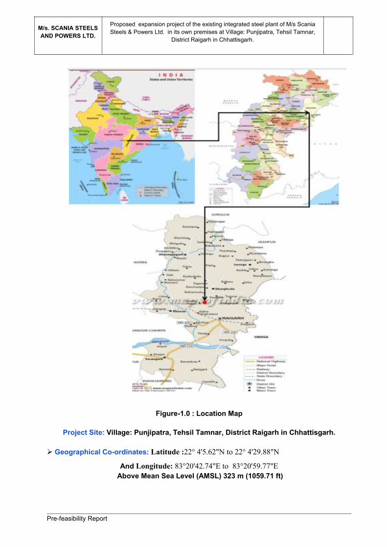
83°21'4.78"E with Above Mean Sea Level of 323 meters (1059.71 ft). Figures 1.0 showsthe location of the project site in Indian map. Figures 2a & 2b show the location of the
project site in Google Earth & Toposheet respectively and Figure 3.0 shows the plant
layout of the project.
Pre-feasibility Report
M/s. SCANIA STEELSAND POWERS LTD.
Proposed expansion project of the existing integrated steel plant of M/s ScaniaSteels & Powers Ltd. in its own premises at Village: Punjipatra, Tehsil Tamnar,
District Raigarh in Chhattisgarh.
Figure-1.0 : Location Map
Project Site: Village: Punjipatra, Tehsil Tamnar, District Raigarh in Chhattisgarh.
Geographical Co-ordinates: Latitude :22° 4'5.62"N to 22° 4'29.88"N
And Longitude: 83°20'42.74"E to 83°20'59.77"EAbove Mean Sea Level (AMSL) 323 m (1059.71 ft)
Pre-feasibility Report
M/s. SCANIA STEELSAND POWERS LTD.
Proposed expansion project of the existing integrated steel plant of M/s ScaniaSteels & Powers Ltd. in its own premises at Village: Punjipatra, Tehsil Tamnar,
District Raigarh in Chhattisgarh.
Figure-2 a: Project Site on Google Earth
Project-feasibility Report
M/s. SCANIA STEELSAND POWERS LTD.
Proposed expansion project of the existing integrated steel plant of M/s ScaniaSteels & Powers Ltd. at Village: Punjipatra, Tehsil Tamnar, District Raigarh in
Chhattisgarh.
Figure - 2 b: Project Site on Toposheet

Project-feasibility Report
M/s. SCANIA STEELSAND POWERS LTD.
Proposed expansion project of the existing integrated steel plant of M/s ScaniaSteels & Powers Ltd. at Village: Punjipatra, Tehsil Tamnar, District Raigarh in
Chhattisgarh.
DRAFT
Figure-3.0 : Proposed Plant Layout

Project-feasibility Report
M/s. SCANIA STEELSAND POWERS LTD.
Proposed expansion project of the existing integrated steel plant of M/s ScaniaSteels & Powers Ltd. at Village: Punjipatra, Tehsil Tamnar, District Raigarh in
Chhattisgarh.
DRAFT
(iii) Details of alternative sites consideration and basis of selecting the proposed site,particularly the environmental considerations gone into should be highlighted. -
The proposed units will be installed on the available land within the existing plant premises of
23.4718 ha (58 acre) as well as on some additional land [12.34291 ha (30.5 acre], adjacent to the
existing plant premises, thus comprising a total land area of 35.81468 hectare (88.5 acres) at Village:
Punjipatra, Tehsil Tamnar, District Raigarh in Chhattisgarh. The additional land is vacant and
industrial in nature. The acquisition of this additional land is under process. The land is generally
flat and does not come under flood zone.
As the proposed project is expansion of the existing steel plant, no alternative sites have been
explored.
(iv) Size or magnitude of operation
The company is planning to expand its existing steel plant by installing some new units on the
available land of its existing plant premises as well as on some additional land, adjacent to its
existing plant premises. The proposed units and their capacities are mentioned below:
(v) Project Description with Process Details
The detail manufacturing process of all the proposed units is as under:
Proposed Units Capacity
Sponge Iron Plant (DRI) 2X350 TPD(Capacity- 2,31,000 TPA)
SMS With Caster 3X20 T with 6/11 CCM(Capacity- 1,85,000 TPA)
Captive power plant 18 MW(WHRB/)+6 MW (AFBC)(Total: 24 MW)
Iron Ore Beneficiation Plant 1 x 2.67 MTPA(Capacity- 26,70,000 TPA)
Pelletization Plant 2X0.8 MTPA(Capacity- 16,00,000 TPA) with dual firing system for 0.8MTPA Each as:
1.Gasifier (50%)-4X6000 m3/h capacity (3 units will be in operation and 1 will beas standby)2.Pulverized Coal Injection (40%)- 1X4 mt/hr coal injecting capacity3.Furnace Oil Firing System (10%)- 2X160 kg/h capacity (1 in operation and 1as standby).
Strip Rolling Mill 1 x 400 TPD(Capacity- 1,30,000 TPA)with1 x 8,000 m3/h capacity of Gasifier and Pulverizer
ERW pipe manufacturingunit
1,00,000 TPA
Pipe galvanizing unit Capacity- 30,000 TPATMT Bar Re-Rolling Mill 1,80,000TPA
With 1 x 8,000m3/h capacity of gasifier and pulverizer
Project-feasibility Report
M/s. SCANIA STEELSAND POWERS LTD.
Proposed expansion project of the existing integrated steel plant of M/s ScaniaSteels & Powers Ltd. at Village: Punjipatra, Tehsil Tamnar, District Raigarh in
Chhattisgarh.
DRAFT
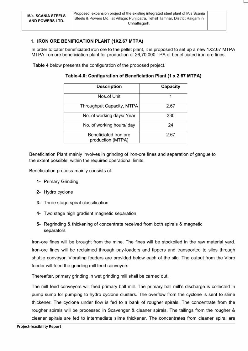
1. IRON ORE BENIFICATION PLANT (1X2.67 MTPA)
In order to cater beneficiated iron ore to the pellet plant, it is proposed to set up a new 1X2.67 MTPAMTPA iron ore beneficiation plant for production of 26,70,000 TPA of beneficiated iron ore fines.
Table 4 below presents the configuration of the proposed project.
Table-4.0: Configuration of Beneficiation Plant (1 x 2.67 MTPA)
Description Capacity
Nos.of Unit 1
Throughput Capacity, MTPA 2.67
No. of working days/ Year 330
No. of working hours/ day 24
Beneficiated Iron oreproduction (MTPA)
2.67
Beneficiation Plant mainly involves in grinding of iron-ore fines and separation of gangue tothe extent possible, within the required operational limits.
Beneficiation process mainly consists of:
1- Primary Grinding
2- Hydro cyclone
3- Three stage spiral classification
4- Two stage high gradient magnetic separation
5- Regrinding & thickening of concentrate received from both spirals & magneticseparators
Iron-ore fines will be brought from the mine. The fines will be stockpiled in the raw material yard.
Iron-ore fines will be reclaimed through pay-loaders and tippers and transported to silos through
shuttle conveyor. Vibrating feeders are provided below each of the silo. The output from the Vibro
feeder will feed the grinding mill feed conveyors.
Thereafter, primary grinding in wet grinding mill shall be carried out.
The mill feed conveyors will feed primary ball mill. The primary ball mill’s discharge is collected in
pump sump for pumping to hydro cyclone clusters. The overflow from the cyclone is sent to slime
thickener. The cyclone under flow is fed to a bank of rougher spirals. The concentrate from the
rougher spirals will be processed in Scavenger & cleaner spirals. The tailings from the rougher &
cleaner spirals are fed to intermediate slime thickener. The concentrates from cleaner spiral are
Project-feasibility Report
M/s. SCANIA STEELSAND POWERS LTD.
Proposed expansion project of the existing integrated steel plant of M/s ScaniaSteels & Powers Ltd. at Village: Punjipatra, Tehsil Tamnar, District Raigarh in
Chhattisgarh.
DRAFT
pumped to secondary hydro cyclone. The under flow from cyclone is fed to regrinding mills for
further grinding to required product size. The overflow from the cyclone is fed to concentrate
thickener.
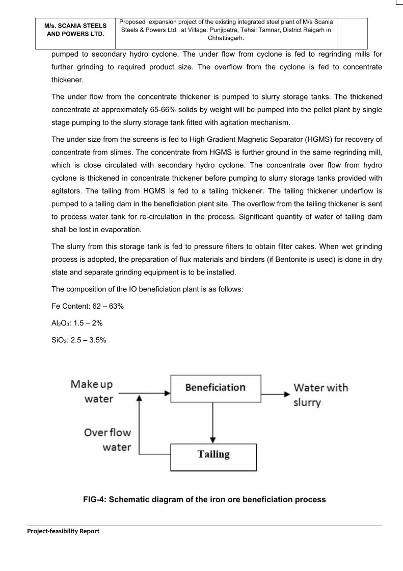
The under flow from the concentrate thickener is pumped to slurry storage tanks. The thickened
concentrate at approximately 65-66% solids by weight will be pumped into the pellet plant by single
stage pumping to the slurry storage tank fitted with agitation mechanism.
The under size from the screens is fed to High Gradient Magnetic Separator (HGMS) for recovery of
concentrate from slimes. The concentrate from HGMS is further ground in the same regrinding mill,
which is close circulated with secondary hydro cyclone. The concentrate over flow from hydro
cyclone is thickened in concentrate thickener before pumping to slurry storage tanks provided with
agitators. The tailing from HGMS is fed to a tailing thickener. The tailing thickener underflow is
pumped to a tailing dam in the beneficiation plant site. The overflow from the tailing thickener is sent
to process water tank for re-circulation in the process. Significant quantity of water of tailing dam
shall be lost in evaporation.
The slurry from this storage tank is fed to pressure filters to obtain filter cakes. When wet grinding
process is adopted, the preparation of flux materials and binders (if Bentonite is used) is done in dry
state and separate grinding equipment is to be installed.
The composition of the IO beneficiation plant is as follows:
Fe Content: 62 – 63%
Al2O3: 1.5 – 2%
SiO2: 2.5 – 3.5%
FIG-4: Schematic diagram of the iron ore beneficiation process
Project-feasibility Report
M/s. SCANIA STEELSAND POWERS LTD.
Proposed expansion project of the existing integrated steel plant of M/s ScaniaSteels & Powers Ltd. at Village: Punjipatra, Tehsil Tamnar, District Raigarh in
Chhattisgarh.
DRAFT
2. PELLETIZATION PLANTM/s SSPL proposes to install a 2X0.8 MTPA pelletization plant to produce 16,00,000 TPA of pellet. The
pelletization plant will be fueled by-
1. Gasifier (50%)- 4X6000 m3/h capacity (3 in operation and 1 as standby)
2. Pulverized Coal Injection (40%)- 1X4 mt/hr coal injecting capacity.
3. Furnace Oil Firing System (10%)- 2 X 160 kg/h capacity (1 in operation and 1 as standby).
The proposed pellet plant is designed to produce iron oxide pellets suitable for use in DRI and Blast
Furnace.
Process Description
The pellet plant will produce oxide pellets suitable for use in DRI kiln. Pellets are heat hardened
balls produced from concentrates and natural iron ores of different mineralogical and chemical
composition. The pellets have improved properties for iron making. Pelletization process involves
feed preparation, green ball formation, pellet Induration and product dispatch.
Iron Ore Pellet Plant
In order to make entire technological level, environment protection level, advanced stage and
suitable for operation and maintenance, it is designed to have some new material, new technology,
new process, new equipment and new structure, with aim at improving reliability, reducing
investment, extending life campaign, lowering operation cost, facilitating maintenance and
replacement.
Travel grate machine - Rotary kiln process features as:
A. Drying, Preheating, Baking, Cooling etc. are carried on different equipment including travel gratemachine, rotary kiln and annular machine, leading to uniform quality of product and reliable andsimplified equipment.
B. Each set of equipment can be controlled individually and adjusted conveniently, which is stronglyadapted for raw material, particularly hematite.
C. Good adaptability for fuel. Low fuel consumption, power consumption and low operation cost.Rotary kiln is step-less adjusted by speed reducer and AC frequency converter to enable operationsmooth and stabilized.
To adopt advanced air flow system, fully recovering sensible heat of high temperature flue gasgenerated from annular cooler, making utilization of thermal energy to the maximum extent andlowering thermal consumption of pellet.
Main operation processes are centralized controlled and adjusted by computer, main technologicalprocesses are monitored and administrated by industrious TV with high automatic control level.
Project-feasibility Report
M/s. SCANIA STEELSAND POWERS LTD.
Proposed expansion project of the existing integrated steel plant of M/s ScaniaSteels & Powers Ltd. at Village: Punjipatra, Tehsil Tamnar, District Raigarh in
Chhattisgarh.
DRAFT
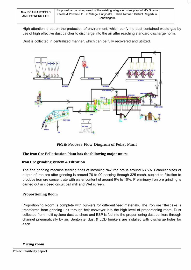
High attention is put on the protection of environment, which purify the dust contained waste gas byuse of high effective dust catcher to discharge into the air after reaching standard discharge norm.
Dust is collected in centralized manner, which can be fully recovered and utilized.
FIG-5: Process Flow Diagram of Pellet Plant
The Iron Ore Pelletization Plant has the following major units:
Iron Ore grinding system & Filtration
The fine grinding machine feeding fines of incoming raw iron ore is around 63.5%. Granular sizes ofoutput of iron ore after grinding is around 70 to 90 passing through 325 mesh, subject to filtration toproduce iron ore concentrate with water content of around 9% to 10%. Preliminary iron ore grinding iscarried out in closed circuit ball mill and Wet screen.
Proportioning Room
Proportioning Room is complete with bunkers for different feed materials. The Iron ore filter cake istransferred from grinding unit through belt conveyor into the high level of proportioning room. Dustcollected from multi cyclone dust catchers and ESP is fed into the proportioning dust bunkers throughchannel pneumatically by air. Bentonite, dust & LCD bunkers are installed with discharge holes foreach.
Mixing room
Project-feasibility Report
M/s. SCANIA STEELSAND POWERS LTD.
Proposed expansion project of the existing integrated steel plant of M/s ScaniaSteels & Powers Ltd. at Village: Punjipatra, Tehsil Tamnar, District Raigarh in
Chhattisgarh.
DRAFT
Iron ore fines, Bentonite, flux, coke and ESP dust are all mixed uniformly in a mixer. As per watercontent of material, some certain quantities of water are added so as to maintain watercontent beforeballing process ranged from 9 to 10%.
Balling Room
Mixed material is transferred through belt conveyor into the high level of balling room, where thematerial mix is discharged through plough-type dumper above belt conveyor separately into mixedmaterial bunker, under which, balling discs are installed. Green ball produced from balling disc istransferred from collective belt conveyor into the green ball distribution system in the travel gratemachine for material distribution.
Green ball distribution system
Green ball from balling room is fed into the distribution system through belt conveyor. In reciprocatingprocess, head swinging belt conveyor feed the green ball into large ball roll screen for screening.Unqualified green ball of more than 16 mm is separated out and then fed back into the balling roomthrough return material system. Green ball of less than 16mm is fed onto wide belt conveyor, whichtransfers the green ball onto roll distributor through AC frequency converter. Roll distributor fedqualified green ball of 5-16 mm onto travel grate machine. Undersized balls less than 5 mm arerecycled to the balling system.
Baking System
Travel grate machine, rotary kiln and annular circular machine are designed to formulate bakingsystem. Green balls are dried and preheated in the travel grate machine, and then baked, solidified inthe rotary kiln, cooled in the annular cooler.
/06/2021Travel Grate Machine
Effective length of travel grate machine is 36 meters. Length of wind box is 3 meters. Thetravel grate machine is divided into 4 zones, which are separately for suction drying zone,preheating zone I and preheating zone II.
Drying zone, I & II
In suction drying zone, recoverable hot waste gas suctioned by heat resistant fans from windboxes in preheating zone II penetrates material layer downward from up, to keep green ballfree of water and dried.
A set of main suction blower is provided to exhaust waste gas from wind box into the airthrough ESP.
Preheating Zone, I:
Hot waste gas flow in the preheating zone I is utilized to keep drying green ball throughmaterial layer, in order to assure pellet to sustain high temperature in Preheating Zone II. Hot
Project-feasibility Report
M/s. SCANIA STEELSAND POWERS LTD.
Proposed expansion project of the existing integrated steel plant of M/s ScaniaSteels & Powers Ltd. at Village: Punjipatra, Tehsil Tamnar, District Raigarh in
Chhattisgarh.
DRAFT
waste gas in preheating zone I is merged through main pipes at a side of wind box with hotwaste gas from suction drying zone to be discharged into air all together through ESP, Mainsuction blowers and chimney.
Preheating Zone, II
In preheating zone II, pellet is further heated. Pellet is partially solidified and hardened toachieve certain strength to sustain impact caused by pellet falling from travel grate machineinto the rotary kiln to avoid being crushed in process of rotation of the kiln.
Rotary Kiln
The size of the kiln is Φ4.3 Mtr. X 32 Mtr. Pellet, after preheated by the traveling gratemachine, is discharged into the end of the kiln through scrapper and chute. The kiln isprovided with HFO & producer gas spraying gun in its head. The well baked pellet, isdischarged, after large sizes of pellet is sieved out by fixed screen at the head of the rotarykiln, into the material receiving hopper of annular cooler.
Annular Cooler
Effective area of annular cooler is 55 SqM. The annular cooler consists of Rotary mechanism,Wind Box, Driving Device, Frame, Upper Cover and etc. The pellet, after cooled down tobelow 100 centigrade in the annular cooler, is discharged outside through discharginghopper.
Project-feasibility Report
M/s. SCANIA STEELSAND POWERS LTD.
Proposed expansion project of the existing integrated steel plant of M/s ScaniaSteels & Powers Ltd. at Village: Punjipatra, Tehsil Tamnar, District Raigarh in
Chhattisgarh.
DRAFT
04/06/Main air suction blowers
Waste gas from preheating zone I merge with those from Wind Box of Suction drying zone isdischarged through ESP and main chimney into the air. Dust content of waste gas to bedischarged into the air is not more than 40mg/Nm3.
Finished Product
Cooled pellet, after discharged from material discharging hopper of annular cooler, istransferred through belt conveyor into the Junction Box, where the cooled pellet 100 to 150deg C is transferred through metal belt conveyor into the finished product transportationsystem. Then pellet is withdrawn by the reclaimer when necessary, and they are loaded bytruck and transported outside.
Coal Gasifier for the Pelletizing Plant
Coal gasification process is one of the cleanest technologies currently available. In theprocess of coal gasification, water gas is produced with zero fugitive emission. The coalgasification process stands better in comparison to other fuels and there is about 50%reduction in the air emissions. From environmental point view, the usage producer gasthrough Coal Gasifier has proven lowest NOx, SOx, particulate matter and lower hazardousair pollutants. Ash is in the form of small clinkers /granules and also be slightly wet whendisposed. Therefore, it does not fly and being used for brick making. Water used in theprocess is either converted into steam or re-circulated; therefore, there is no waste waterstream.
In view of better efficiency of heat in kilns and clean coal technology, the company hasadopted dual firing system utilizing producer gas and heavy furnace oil in the ratio of70:30% in both the Pelletizing Plants.
Process Description: The Coal Gasification Facility consists of:
1. Coal conveying from ground hopper to top of battery of coal Gasifiers2. Coal Gasifiers3. Hot gas clean-up system consisting of gravity settlers & cyclones4. Insulated gas piping5. Process water system6. Ash handling consisting of ash conveyor and storage hopper7. Instrumentation, automation & control for the entire facility.
The process of gasification primarily consists of partial oxidation of coal to produce producergas. The gasification reactions are carried out in a cylindrical vessel, called a gasifier/pulverized base. The gasifier main reactor is double walled /water jacketed. Water in waterjacket is converted into steam. The mixture of atmospheric air and steam from water jacketreacts with coal in the gasifier reactor to generate producer gas. The gas comes out of thegasifier main reactor at 350oC – 450oC and then passes through gravity settler and cyclonefor removal of course dust particles. The gas from individual Gasifiers travels to common gasduct and then to the kiln. The gas is conveyed to kiln in “hot” condition. So, the ‘tar in vaporform’ & ‘fine carbon particles’ are carried along with gas to the kiln through insulated pipeline
Project-feasibility Report
M/s. SCANIA STEELSAND POWERS LTD.
Proposed expansion project of the existing integrated steel plant of M/s ScaniaSteels & Powers Ltd. at Village: Punjipatra, Tehsil Tamnar, District Raigarh in
Chhattisgarh.
DRAFT
and burn in the kiln.
Air blowers provided with each of the gasifier supply atmospheric air into the Gasifiers. Thesteam from water jacketed double wall mixes with air and enters the gasifier main reactor. Airinlet water seal prevents air from leakage. The excess steam is vented into the atmosphere.
Coal conveyor, coming from the coal handling plant, feeds coal into the coal bunkersprovided on top of each of the gasifier. From the coal bunker, coal enters the gasifier mainreactor through a coal feeding mechanism. The coal feeding mechanism has a double doorarrangement to enable feeding of coal into the reactor while it is in operation.
Ash is discharged from ash pans of individual gasifier on to the ash conveyor, which runsalongside the ash pans of all the Gasifiers. Ash conveyor carries the ash on to the ash heap,from where it is transported for disposal. Ash is in the form of small clinkers / granules andalso be slightly wet when disposed. Therefore, it does not fly. This ash is used for brickmaking.
De-mineralized water (DM water) is used in the water jacket of gasifier main reactor forconversion into steam. DM water is first stored in a common ground tank and then pumped toindividual overhead tanks for further use. Gas generated in the gasifier main reactor isbranched into 2 streams. One stream goes to flare and the other to the main line. Flare lineis used during gasifier start-up only, when the gas does not contain any combustibleconstituents. During start-up, the gas coming out at flare mainly contains CO2& N2. Assoonas the gas lights up at the flare, it is diverted to the main line. Flare water seal isolatesthe flare line from the rest of the system while the Gasifiers are in normal operation.
Gas, traveling to main line, passes through gravity settler, cyclone separator and water sealisolator, into the common gas duct. Gravity settler and cyclone separator separate coarsedust particles from gas while the fine particles are carried to kiln along with gas. Water sealisolator is used for isolating individual Gasifiers from the common duct. Water seals havebeen provided at various locations. Water used in various water seals is re-circulated andreused.

29 | P a g e
M/s. SCANIA STEELSAND POWERS LTD.
Proposed expansion project of the existing integrated steel plant of M/s ScaniaSteels & Powers Ltd. at Village: Punjipatra, Tehsil Tamnar, District Raigarh in
Chhattisgarh.
0Fuel Firing System
In view of better efficiency of heat in kilns and clean coal technology, the company is adoptingapulverized Coal firing system along with furnace oil in the Pelletizing Plant in addition of coalgas.
There is 1No. of Coal gasifiers of 8000 Nm3/hr, in the 8 lac TPA Pellet Plant in first phase.There is proposal to utilize Coal mix in the Gasification Plant in place of oil.
Source of Major Raw Material
Iron ore fines: Iron ore fines are purchased from the iron ore belt of Joda-Barbil region. Coke/Coal Fines: From IOCL, Paradeep (Imported Coke/Coal). Dolomite: Dolomite is sourced from Bilaspur state of Chhattisgarh and
Sundergarh district of Odisha. 4-Bentonite: Bentonite is from local traders of Bhuj, Gujarat product.
3. SPONGE IRON PLANT (DRI)M/s Scania Steels and Powers Ltd. is proposing to install 2X350 TPD DRI kilns in addition
to its existing 4X100 TPD DRI Kilns for the overall sponge iron production to the tune of
3,63,000 TPA, which will be used as raw material in Induction Furnaces.
Manufacturing ProcessThe proposed project shall use the coal based process in which iron oxide in pellet / iron ore
will be reduced with non coking coal in a rotary kiln to make sponge iron. The raw materials
(Pellet / iron ore, coal and dolomite), in desired quantities and sizes, are fed into the rotary kiln
from the feed end, after the rotary kiln has been fired and reaches the desired temperature.
The rotary kiln is a refractory lined cylindrical vessel on which blowers and air pipes are
mounted to provide combustion air to the kiln. The rotary kiln has a downward slope and is
mounted on rollers to enable rotation. The angle of inclination, rotational speed, and length of
time the charge is exposed to the atmosphere and temperature has important bearings on the
quality of the end product. The rotary kiln has three functions as: It is a heat exchanger,
Vessel for chemical reaction, Conveyor for solids.
With the rotation of the kiln, the charge moves down the slope and the surface of the material
is exposed to heat. The heat exchange takes place via the non-refractory lining of the kiln.
The reduction from oxide to metal occurs by gradual removal of oxygen at various
temperatures giving rise to various intermediate oxides. Hot sponge iron is discharged from
the kiln discharge end and taken into the rotary cooler. The effluent gas that contains coal
volatile matter, fine carbon particles, iron fines and sponge iron dust is treated separately in
the waste gas handling system. The system consists of:
30 | P a g e
M/s. SCANIA STEELSAND POWERS LTD.
Proposed expansion project of the existing integrated steel plant of M/s ScaniaSteels & Powers Ltd. at Village: Punjipatra, Tehsil Tamnar, District Raigarh in
Chhattisgarh.
a) Dust settling chamber
b) After burner chamber
c) Waste heat recovery boiler
d) Electrostatic precipitator
e) ID fan
f) Chimney
Direct Reduced Iron / Sponge Iron Process (DRI)The process of reduction takes place inside the rotary kiln, which is mounted on tyres and
supported by support rollers. The transverse motion of the kiln is controlled with the help of
hydro thruster and thrust rollers. The kiln is rotated at the rate of 0.35 rpm with the help of a
girth gear mounted on the kiln and connected with pinion drives, which in turn are coupled
with gear boxes and motors.
The direct reduction of iron oxides inside the kiln is held due to CO gas, which is generated
out of coal at nearly 950°C. Shell air fans are mounted on the kiln, which inject air in
controlled manner into the kiln for creating reducing atmosphere. The CO reacts with Fe2O3
and reduces it to Fe. The kiln is lined with refractory for sustaining the high temperature.
The hot sponge iron is then cooled by indirect cooling inside a cooler. The rotary cooler is
supported on tyres and support rollers. The cooler is rotated at the rate of 0.6 rpm with the
help of a girth gear mounted on the cooler and connected with single pinion drive, which is
coupled with a gearbox and motor. The water is sprayed on the cooler shell while the sponge
iron travels inside the cooler and hence, the material gets cooled at outlet to 150°C while
discharged on the product conveyor.
In the kiln, the iron oxide will be heated to the reduction temperature of 1000-1050°C. The iron
oxide of the ore will be reduced to metallic iron by carbon dioxide generated in the kiln from
coal. The heat required for the reduction process will also be supplied by the combustion of
coal.
Thermocouple will be installed along the length of the kiln shell for measurement of thermal
profile of the kiln. The temperature will be controlled by regulating the amount of combustion
air admitted into the kiln through no. of ports with help of fans mounted on the kiln will have
variable speed drive. Auxiliary drive is provided for slow rotation.
The cooler will be lined with refractory castable for about 4.0 m from the feed end. Bypass
arrangement will be provided at discharge end of the cooler for emergency discharge of

31 | P a g e
M/s. SCANIA STEELSAND POWERS LTD.
Proposed expansion project of the existing integrated steel plant of M/s ScaniaSteels & Powers Ltd. at Village: Punjipatra, Tehsil Tamnar, District Raigarh in
Chhattisgarh.
materials. The cooled product will be conveyed to the product processing building by a
system of belt conveyors.
The cooling water will be collected in the trough below the cooler and sent to the cooling
tower for cooling. The cooled water will be re-circulated. Closed circuit cooling system will be
followed in the plant.
Product SeparationThe sponge iron along with unburnt coal in the form of dolochar comes out of the cooler. The
sponge iron being magnetic is separated out of the dolochar by passing it through a magnetic
separator. The sponge iron and char, recovered separately, are stored in the storage bunkers
and discharged through trucks.
Off gas cleaning systemThe off gases moving in counter current of material flow inside the kiln are at a temperature of
1000°C and carry coal dust, which is passed through dust settling chamber and after burning
chamber (ABC). Air is added into the ABC for converting CO to CO2. The hot flue gas stream
is taken to the waste heat recovery boiler (WHRB) for utilization of the sensible heat for
making steam. The off gases are then allowed to pass through ESP for removal of dust so
that the concentration of dust is limited to below 30 mg/Nm3 before being discharged from the
chimney.
In-plant de-dusting systemReverse air bag filter shall be installed for catching the dust from various conveyors, material
handling equipment and-product handling equipment. The dust collected from the bag filter
shall be conveyed pneumatically to a distant location and discharged on trucks in wet
condition.
Raw Materials required for Sponge Iron manufactureThe main raw materials for sponge iron production are pellet / iron ore, coal, and dolomite.
Preferred Raw Material CharacteristicsThe principal raw material will be used for production of steel making grade DRI in the sponge
making process is pellet / iron ore, non-coking coal and dolomite.
The pellet/iron ore should be preferably high in Fe content (>62% Fe). Coal with a high
reactivity and high fusion temperature is preferred. The coal should also be non-coking.

32 | P a g e
M/s. SCANIA STEELSAND POWERS LTD.
Proposed expansion project of the existing integrated steel plant of M/s ScaniaSteels & Powers Ltd. at Village: Punjipatra, Tehsil Tamnar, District Raigarh in
Chhattisgarh.
A low ash fusion temperature is undesirable as it promotes formation of accretions in the kiln.
The coal ash composition is also important as a siliceous ash might react with ferrous oxide to
form low melting ferrous silicate and interfere with the reduction to metallic iron.
Product characteristics of Sponge Iron are presented in Table-4.0.
Table-4.0 : Sponge Iron (coal based) characteristics
Fe (total) 92% min
Fe (met) 83 % max
Metallization 90 % max
Carbon 0.25 % max
S 0.025% max
P 0.06% max
Re-oxidation Non-pyrophoric characteristics
Major plant facilitiesThe major plant facilities for the sponge iron plant envisaged are as follows:
1. Day bins
2. Rotary kiln and cooler
3. Off gas system including waste heat power generation
4. Product processing and storage.
Day binsThere shall be a day bin building to cater to raw material requirement of the kiln. These bins will
generally have storage of about one day’s requirement of pellet, feed coal (4-8, 8-18 mm) &
dolomite (1-4 mm). Weigh feeders will be provided to draw the required quantity of various
materials in proportion from the bins and the same will be conveyed to the kiln feed and
discharge end.
Rotary kiln and coolerThe rotary kilns with 5 m of diameter, 125 m length will be provided for reduction of iron oxides
into sponge iron using non-coking coal as reductant. The kiln will be lined with abrasion resistant
refractory castables throughout its length with damps at feed end and discharge end.
The rotary kiln will be supported on four piers. A slope of about 2.5% shall be maintained. Then
main drive of the kiln will be by A.C motors with VVF drive control. The speed of the kiln will be
in the range of 0.3-0.9 & 1.05-3.15 rpm. The auxiliary drive of the kiln will be by A.C motors.
33 | P a g e
M/s. SCANIA STEELSAND POWERS LTD.
Proposed expansion project of the existing integrated steel plant of M/s ScaniaSteels & Powers Ltd. at Village: Punjipatra, Tehsil Tamnar, District Raigarh in
Chhattisgarh.
The other main components of the kiln will be as given below:
a. Feed end and discharge end transition housing of welded steel construction with
refractory lining including feed chute.
b. Pneumatic cylinder actuated labyrinth air seal complete with auto lubricating at feed
end and discharge end.
c. On board equipment like fans, manifolds, ports, slip ring, instrumentation etc.
d. Cooling fans at feed end and discharge end.
e. Feed end double pendulum valve & dust valves.
Product processing and storageThere shall be one product processing unit for handling the cooler discharge. The product
containing sponge iron, char and spent lime from the cooler discharge end will be discharged to
a set of conveyors and sent to the product processing building. The kiln cooler system shall
have a separate surge bin. Product from surge bin can be withdrawn through vibrating feeder
and to the product will first be screened in a double deck screen having 3 mm and 20 mm
screens. +20 materials shall be dumped as rejects. The screened product i.e. +3 – 20 mm and -
3 mm fraction shall separately be sent to the product storage separation. Sponge iron lump (3 –
20) shall be sent to the product storage building for storing in two no. of bunkers where three
days storage has been proposed. The sponge ion fines (-3 mm) will be stored in the fines
bunker in the product processing building itself where one day storage will be provided. The
sponge iron lump and fines will be further conveyed from the respective bunkers by truck to the
steel making unit as per the requirement. The char/non-magnetic shall be stored in a separate
bin from where it will be sent to the power plant through conveyors for its utilization for power
generation in FBC boiler. Indicative process flow diagram of DRI Plant is presented below in
Figure 6.0.

34 | P a g e
M/s. SCANIA STEELSAND POWERS LTD.
Proposed expansion project of the existing integrated steel plant of M/s ScaniaSteels & Powers Ltd. at Village: Punjipatra, Tehsil Tamnar, District Raigarh in
Chhattisgarh.
Figure-6.0 : Process flow diagram of DRI plant
4. STEEL MELTING SHOP
The company has proposed to install 3X20T of IFs in addition to its existing 1X6T + 1X8T IFs
(Implemented but not under operation) and 2 x15T (not yet installed) with matching LRF & CCM
for the overall production of 320000 TPA of billets.
The plant will produce steel in the form of billets, Steel Sheet, Electric Resistance Welded pipes
through IF-CCM-RM route. Steel making will be done using induction furnaces. A brief
description of the process is dealt in subsequent paragraphs and the process flow sheet is given
below in Figure 7.0.

35 | P a g e
M/s. SCANIA STEELSAND POWERS LTD.
Proposed expansion project of the existing integrated steel plant of M/s ScaniaSteels & Powers Ltd. at Village: Punjipatra, Tehsil Tamnar, District Raigarh in
Chhattisgarh.
Figure-7.0 : Process flow diagram of SMS unit with CCM
Steel Making by Induction FurnaceThe greatest advantage of the Induction Furnace is its low capital cost compared with other
types of Melting Units. Its installation is relatively easier and its operation simpler. Among other
advantages, there is very little heat loss from the furnace as the bath is constantly covered and
there is practically no loss during its operation. The molten metal in an Induction Furnace is
circulated automatically by electromagnetic action so that when alloy additions are made, a
homogeneous product is ensured in minimum time. The time between tap and charge, the
charging time, power delays etc. are items of utmost importance is meeting the objective of
maximum output in tones/hours at a low operational cost. The disadvantage of the induction
furnace is that the melting process requires usually selected scrap because major refining is not
possible.
The process for manufacturing steel may be broadly divided into the following stages:
i. Melting the charge mixed of steel & Iron scrap
ii. Ladle teeming practice for Casting (OR)
iii. Direct teeming practice for billet Casting unladdable teeming machine
The furnace is switched on, current starts flowing at a high rate and a comparatively low voltage
through the induction coils of the furnace, producing an induced magnetic field inside the central
36 | P a g e
M/s. SCANIA STEELSAND POWERS LTD.
Proposed expansion project of the existing integrated steel plant of M/s ScaniaSteels & Powers Ltd. at Village: Punjipatra, Tehsil Tamnar, District Raigarh in
Chhattisgarh.
space of the coils where the crucible is located. The induced magnetic fluxes thus generated out
through the packed charge in the crucible, which is placed centrally inside the induction coil.
As the magnetic fluxes generated out through the scraps and complete the circuit, they generate
and induce eddy current in the scrap. This induced eddy current, as it flows through the highly
resistive bath of scrap, generates tremendous heat and melting starts. It is thus apparent that
the melting rate depends primarily on two things (1) the density of magnetic fluxes and (2)
compactness of the charge. The charge mixed arrangement has already been described. The
magnetic fluxes can be controlled by varying input of power to the furnace, especially the current
and frequency.
In a medium frequency furnace, the frequency range normally varies between 150-10K cycles /
second. This heat is developed mainly in the outer rim of the metal in the charge but is carried
quickly to the center by conduction. Soon a pool of molten metal forms in the bottom causing the
charging to sink. At this point any remaining charge mixed is added gradually. The eddy current,
which is generated in the charge, has other uses. It imparts a molten effect on the liquid steel,
which is thereby stirred and mixed and heated more homogeneously. This stirring effect is
inversely proportional to the frequency of the furnace and so that furnace frequency is selected
in accordance with the purpose for which the furnace will be utilized.
The melting continues till all the charge is melted and the bath develops a convex surface.
However, as the convex surface is not favorable to slag treatment, the power input is then
naturally decreased to flatten the convexity and to reduce the circulation rate when refining
under a reducing slag. The reduced flow of the liquid metal accelerates the purification reactions
by constantly bringing new metal into close contact with the slag. Before the actual reduction of
steel is done, the liquid steel which might contain some trapped oxygen is first treated with some
suitable deoxidizer. When no purification is attempted, the chief metallurgical advantages of the
process attributable to the stirring action are uniformity of the product, control over the super
heat temperature and the opportunity afforded by the conditions of the melt to control de-
oxidation through proper addition.
As soon as the charge has melted clear and de-oxidising ions have ceased, any objectionable
slag is skimmed off, and the necessary alloying elements are added. When these additives have
melted and diffused through the bath of the power input may be increased to bring the
temperature of metal up to the point most desirable for pouring. The current is then turned off
and the furnace is tilted for pouring into a ladle. As soon as pouring has ceased, any slag
adhering to the wall of the crucible is crapped out and the furnace is readied for charging again.
As the furnace is equipped with a higher cover over the crucible very little oxidation occurs
during melting. Such a cover also serves to prevent cooling by radiation from the surface heat

37 | P a g e
M/s. SCANIA STEELSAND POWERS LTD.
Proposed expansion project of the existing integrated steel plant of M/s ScaniaSteels & Powers Ltd. at Village: Punjipatra, Tehsil Tamnar, District Raigarh in
Chhattisgarh.
loss and protecting the metal is unnecessary, though slags are used in special cases. Another
advantage of the induction furnace is that there is hardly any melting loss compared with the arc
furnace.
A metal Recovery Plant is proposed to recover the metals from the stag, to be generated.
Continuous casting machine 6/11The molten steel from the IF is cast in a continuous casting machine to produce billets. In some
processes, the cast shape is torch cut to length and transported hot to the hot rolling mill for
further processing. Other steel mills have reheat furnaces. Steel billets are allowed to cool, and
then be reheated in a furnace prior to rolling the billets into bars or other shapes.
The process is continuous because liquid steel is continuously poured into a ‘bottomless’ mould
at the same rate as a continuous steel casting is extracted.
Before casting begins a dummy bar is used to close the bottom of the mould.
A ladle of molten steel is lifted above the casting machine and a hole in the
bottom of the ladle is opened, allowing the liquid steel to pour into the mould to
form the required shape.
As the steel’s outer surface solidifies in the mould, the dummy bar is slowly
withdrawn through the machine, pulling the steel with it.
Water sprays along the machine to cool/ solidify the steel.
At the end of the machine, the steel is cut to the required length by on line PLC
based hot shearing machine.
After cut, hot billets will directly go to rolling mill through conveyer.
5. Rolling Mill
M/s Scania Steels and Powers Ltd. has proposed to install two types of rolling mills viz., Strip
Rolling Mill and TMT Bar re-rolling mill with individual preheating systems as standby
arrangement. However, the pre-heating system will not be required during normal plant
operation when there will be hot billet charging to the rolling mills. A brief description of both the
types of rolling mills has been described below:
STRIP MILL (STRIP/SHEET/COIL)
Semi-finished product from the CCM of IF will be converted into finished products such as strip,
sheet, coil, wire, bar and wire rope (Capacity 1,30,000 TPA).
38 | P a g e
M/s. SCANIA STEELSAND POWERS LTD.
Proposed expansion project of the existing integrated steel plant of M/s ScaniaSteels & Powers Ltd. at Village: Punjipatra, Tehsil Tamnar, District Raigarh in
Chhattisgarh.
Manufacturing process of Conventional Rolling Mill:
I. Ingot/ Billet after proper sizing through Gas Cutting or billet Shearing Machine willbe pushed in reheating furnace. The reheating furnace will be fired by F.O./ Coalbased producer gas plant. There will be high energy efficiency heat recuperatorsinstalled in with it.
II. Then pushed out to rolling stands for re-rolling. Steel Pieces are rolled through allstands in order to get required shape of finished goods i.e., MS Strips and otherRerolled products. It is proposed to produce MS Strips at present; however, infuture the Mills may be used to produce Wire Rod or other Rerolled products also.
III. After Cooling rerolled products are shifted to finished yard, after inspection, areready for dispatch to tube mill/stock yard.
Rolling Mill for TMT bars
The company proposes to install a re-rolling mill of 1,80,000 TPA capacity. The fuel for the
reheating furnace will be producer gas, which will be produced in the proposed producer gas
plant.
TMT BarsTMT or Thermo Mechanically Treated bars are high-strength reinforcement bars having a
hardened outer core and a soft inner core. They are manufactured under a process called
Thermo Mechanical Treatment, after which they are named.
Steel – an alloy of iron, carbon, and other elements – is a major component used in buildings,
infrastructure, tools, ships, automobiles, machines etc., because of its high tensile strength.
However, steel structures are adversely affected by corrosion, fire and other environmental and
accidental factors, thus severely compromising their structural integrity, safety, and longevity.
Thus, steel is subjected to various processes to increase its mechanical properties like ductility,
hardness, corrosion resistance, and yield strength. Thermo Mechanical Treatment (TMT) is one
of these many processes; it combines mechanical or plastic deformation processes like
compression or forging, rolling etc. with thermal processes like heat-treatment, water quenching,
and heating and cooling at various rates into a single process.
The steps included in Thermo Mechanical Treatment Process are as follows:

39 | P a g e
M/s. SCANIA STEELSAND POWERS LTD.
Proposed expansion project of the existing integrated steel plant of M/s ScaniaSteels & Powers Ltd. at Village: Punjipatra, Tehsil Tamnar, District Raigarh in
Chhattisgarh.
Heating, rolling, and forming of reinforced bar: The Hot steel billets from CCM at
approximately 1200°C to 1250°C and then rolled to reshape the billets into the final size and
shape of reinforced bar (rebar) by passing the billets through a rolling mill stand.
Quenching: When the hot reinforced bar leaves the final rolling mill stand, it is instantaneously
quenched – a type of heat treatment where the rebars are rapidly cooled by water in a
quenching box to obtain certain material properties. Quenching prevents the occurrence of
undesired processes such as phase transformations. It accomplishes this by reducing the time
frame during which these undesired reactions have a higher chance of occurring. Also, the
sudden drastic change in temperature toughens the outer layer of the steel bar, thus enhancing
its tensile strength and durability. This is because quenching converts the outer surface of the
reinforced bar to Martensite, a hard form of steel and causes it to shrink, which in turn
pressurizes the core, thus helping to form the correct crystal structures. As a result of this
process, the surface of the quenched bar becomes cold and hardened, while the core still
remains hot.
Self-tempering: After leaving the quenching box, a temperature gradient is formed through the
cross-section of the quenched bar. As a result, heat flows from the core, as it is at a relatively
higher temperature to the outer surface. This causes the correct tempering of the outer
martensitic layer into a structure called Tempered Martensite and the formation of an
intermediate ring of Martensite and Bainite (a plate-like microstructure). The core still stays in
the austenitic (a typical cubical crystalline structure, commonly called as gamma-phase iron)
state at this stage.
Atmospheric Cooling: After the self-tempering process, the bars are subjected to atmospheric
cooling to equalize the temperature difference between the soft inner core and the hardened
exterior. Once the bars are completely cooled down, the austenitic core gets transformed into a
ductile ferrite-pearlite structure.
Therefore, the cross-section of the final product demonstrates a variation in its crystal
microstructure having a tough, strong, tempered martensite in its outermost layer, an
intermediate layer of Martensite and Bainite, and a refined, tough and ductile ferrite and pearlite
core.
On the other hand, lower grades of rebar are twisted when cold to harden them in order to
increase their strength. However, TMT bars do not need hardening explicitly as the quenching
process accomplishes this. Since TMT does not involve any twisting, no torsional stress occurs,
which does remove the chances of surface defects forming in TMT bars. Hence, TMT bars are
less susceptible to corrosion as opposed to cold, twisted, and deformed (CTD) bars.
40 | P a g e
M/s. SCANIA STEELSAND POWERS LTD.
Proposed expansion project of the existing integrated steel plant of M/s ScaniaSteels & Powers Ltd. at Village: Punjipatra, Tehsil Tamnar, District Raigarh in
Chhattisgarh.
The production quality of TMT bar depends on three major factors:
Quality of raw materials.
A properly designed and automated rolling mill stand.
A well-designed quenching and tempering technology.
TMT bars, having a uniform and concentrated hardened periphery and a considerably softer
core, will have the desired tensile strength coupled with high elongation as required in the
construction of buildings located in areas with regular seismic activity.
6. Producer gas plantProducer gas is the cheapest fuel and can substitute Furnace Oil, LDO, Kerosene, other fuel
and other gases. It is ideally adopted to industrial heating operation, because of its uniformity &
cleanliness. The company proposes to install producer gas plant the details of which is furnished
below:
1.Gasifier- 4X6000m3/h capacity (3 in operation and one as standby) for pellet plant.
2 nos. 8,000 Nm3/h capacity producer gas plant along with 2 nos. coal pulverizers, one for the
proposed Strip Rolling Mill & another for the proposed Re-Rolling Mill.
Producer gas is generated by injecting a blast of air and steam through a layer of incandescent
coal or coke. The carbon of the coal or cock combines with oxygen of the air to from carbon
dioxide and the carbon dioxide as it goes up meets hot unburnt coal or cock in reduction zone to
form carbon monoxide. The water vapors which passes through the fuel reacts to form carbon
monoxide and hydrogen.
The chief combustible elements in producer Gas are carbon monoxide and some hydrocarbon.
Gasification is a major & unique element in the development of advance, improved, Renewable
energy system. It is a thermo-chemical process that converts solid biomass coal/ bio-coal to a
low heat value (LHV) gaseous fuel "Producer Gas". This Producer Gas is fuel for many different
application of thermal power in the equipment like Furnaces, Kilns dryers, rolling mills and heat
treatment equipment. Boiler, Hot air Generator.
The equipment to be utilized for gasification is known as a Gasifier. On the basis of flow of gas
in the reactor, gasifier is generally divided into two major groups like UPDRAFT and Downdraft
Gasfire. An updraft Gasifire is more efficent & generally utilized for Thermal application. Figure8.0 (a & b) show the schematic diagrams of Updraught & Downdraught Gasifiers.
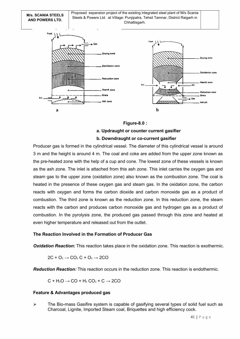
41 | P a g e
M/s. SCANIA STEELSAND POWERS LTD.
Proposed expansion project of the existing integrated steel plant of M/s ScaniaSteels & Powers Ltd. at Village: Punjipatra, Tehsil Tamnar, District Raigarh in
Chhattisgarh.
Figure-8.0 :a. Updraught or counter current gasifierb. Downdraught or co-current gasifier
Producer gas is formed in the cylindrical vessel. The diameter of this cylindrical vessel is around
3 m and the height is around 4 m. The coal and coke are added from the upper zone known as
the pre-heated zone with the help of a cup and cone. The lowest zone of these vessels is known
as the ash zone. The inlet is attached from this ash zone. This inlet carries the oxygen gas and
steam gas to the upper zone (oxidation zone) also known as the combustion zone. The coal is
heated in the presence of these oxygen gas and steam gas. In the oxidation zone, the carbon
reacts with oxygen and forms the carbon dioxide and carbon monoxide gas as a product of
combustion. The third zone is known as the reduction zone. In this reduction zone, the steam
reacts with the carbon and produces carbon monoxide gas and hydrogen gas as a product of
combustion. In the pyrolysis zone, the produced gas passed through this zone and heated at
even higher temperature and released out from the outlet.
The Reaction Involved in the Formation of Producer Gas
Oxidation Reaction: This reaction takes place in the oxidation zone. This reaction is exothermic.
2C + O₂→ CO₂ C + O₂→ 2CO
Reduction Reaction: This reaction occurs in the reduction zone. This reaction is endothermic.
C + H₂O → CO + H₂ CO₂ + C → 2CO
Feature & Advantages produced gas
The Bio-mass Gasifire system is capable of gasifying several types of solid fuel such asCharcoal, Lignite, Imported Steam coal, Briquettes and high efficiency cock.
a b

42 | P a g e
M/s. SCANIA STEELSAND POWERS LTD.
Proposed expansion project of the existing integrated steel plant of M/s ScaniaSteels & Powers Ltd. at Village: Punjipatra, Tehsil Tamnar, District Raigarh in
Chhattisgarh.
Low Nox formation due to low flame temperature.
Extermely Low particulates and smoke emission due to the complete direct firing ofProducer
Gas compare to solid fules / liquid fules firing
Worldwide accepted environment friendly Renewable technology.
Chemical Composition of Producer Gas (Approx)
The chemical composition of producer gas is as follows:
Carbon dioxide : 3%
Hydrogen gas : 10- 15 %
Carbon monoxide : 22 - 30 %
Nitrogen gas : 50 - 55 %
Methane : 6%
Waste management in Produced Gas Plant
Ash generated during the gasification process travels down into the ash pan placed below the
reactor. The ash pan is slowly rotated to facilitate discharge of ash from pan onto the ash
conveyor. Ash pan also contains water, into which the bottom of the reactor is dipped. This
creates a rotating water seal joint for discharge of ash through the water seal. The ash conveyor
carries ash from each of the gasifiers to the ash dump (ash bunker). From the ash dump (ash
bunker), the ash will be periodically removed and used in cement plant and brick manufacturing.
Gas coming out of individual gasifier reactors will be hot and raw. The gas cooling & cleaning
system consists of indirect cooling type centrifugal tar separators and electrostatic precipitators.
Hot-raw gas, exiting from the gasifiers will first be cooled and about 80% tar is separated in
centrifugal tar separators. Gas from these separators goes to a common header to be conveyed
to electrostatic tar separators. Tar from centrifugal tar separators gets collected in individual
collection pots and then is pumped to tar storage. Cooling water is continuously circulated to tar
separators for external cooling of gas. The temperature of cooling water is maintained within
limits with the help of cooling towers.
Residual tar in gas is separated out in electrostatic tar precipitators. The tar, so separated, will
be first collected in tar pits and then transferred to tar tanks for storage. Tar has a good market
value and will be sold to authorized vendor.
Various water seals are used for isolation of gas within the gasifier block, along the gas pipeline
and in the gas utilization area. Water used in the seals will be collected when the seals are
emptied and the same water is re-used for filling the seals. So, there is no regular disposal of
43 | P a g e
M/s. SCANIA STEELSAND POWERS LTD.
Proposed expansion project of the existing integrated steel plant of M/s ScaniaSteels & Powers Ltd. at Village: Punjipatra, Tehsil Tamnar, District Raigarh in
Chhattisgarh.
seal water. But there could be occasional disposal of seal-water. Such water (which would
contain traces of phenols) would be incinerated in the after burning chambers of sponge iron
kilns.
Coal Tar generated from PGP shall be collected using “Centrifugal Tar Separator” and will be
used as Fuel in DRI Kiln / alternately sold to authorize re-processors. No waste water will be
generated from the process.
CENTRIFUGAL TAR SEPARATOR
Indirect Type Centrifugal Tar Separator’ consists of 2 stages of indirect cooling of gas and
simultaneous centrifugal tar separation. As can be seen in the figure, gas rises upwards from the
water seal into the first stage of separator. At the top of first stage, high velocity centrifugal
motion is imparted to gas to separate out droplets of tar. As the gas travels down in the outer
annular path, it is cooled by external forced cooling. At the same time, condensed and separated
tar travels down along the wall of the annular path. As the gas enters the second stage, it is
cooled and therefore tar separation is more effective. Here, again, similar action of high velocity
centrifugal separation and indirect forced cooling is repeated.
PHENOLIC WATER, TAR & TAR SLUDGE RECOVERY SYSTEM
Phenolic wastewater generated during the stage of gas cooling shall be charged in the ABC of
DRI plant and will also be used for making green ball for using it in pellet kiln. Over flow water,
spillage water will be connected to underground tank, where the tar will be settled. Soft water
plant will be installed so as pH is maintained. Plant will be designed for Zero discharge and
spillage water will be used for spraying on coal and coke if necessitated.
7. ERW PIPE MANUFACTURING UNIT
The company has planned to set up a new ERW pipe manufacturing unit for the production of
1,00,000 TPA of ERW pipe. In Electric Resistance Welding (ERW) process, pipe is
manufactured by cold-forming a flat sheet of steel into a cylindrical shape. Then current is
passed between the two edges of the steel cylinder to heat the steel to a point at which the
edges are forced together to form a bond without the use of welding filler material. Several
Electric Resistance Welding (ERW) processes are available for pipe production. The two main
types of ERW are:
(i) High Frequency Welding
(ii) Rotary Contact Wheel Welding.
(i) High Frequency Welding
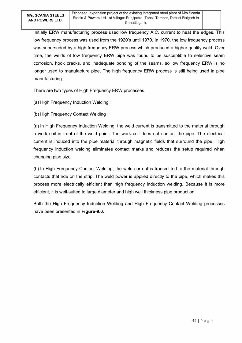
44 | P a g e
M/s. SCANIA STEELSAND POWERS LTD.
Proposed expansion project of the existing integrated steel plant of M/s ScaniaSteels & Powers Ltd. at Village: Punjipatra, Tehsil Tamnar, District Raigarh in
Chhattisgarh.
Initially ERW manufacturing process used low frequency A.C. current to heat the edges. This
low frequency process was used from the 1920’s until 1970. In 1970, the low frequency process
was superseded by a high frequency ERW process which produced a higher quality weld. Over
time, the welds of low frequency ERW pipe was found to be susceptible to selective seam
corrosion, hook cracks, and inadequate bonding of the seams, so low frequency ERW is no
longer used to manufacture pipe. The high frequency ERW process is still being used in pipe
manufacturing.
There are two types of High Frequency ERW processes.
(a) High Frequency Induction Welding
(b) High Frequency Contact Welding
(a) In High Frequency Induction Welding, the weld current is transmitted to the material through
a work coil in front of the weld point. The work coil does not contact the pipe. The electrical
current is induced into the pipe material through magnetic fields that surround the pipe. High
frequency induction welding eliminates contact marks and reduces the setup required when
changing pipe size.
(b) In High Frequency Contact Welding, the weld current is transmitted to the material through
contacts that ride on the strip. The weld power is applied directly to the pipe, which makes this
process more electrically efficient than high frequency induction welding. Because it is more
efficient, it is well-suited to large diameter and high wall thickness pipe production.
Both the High Frequency Induction Welding and High Frequency Contact Welding processes
have been presented in Figure-9.0.
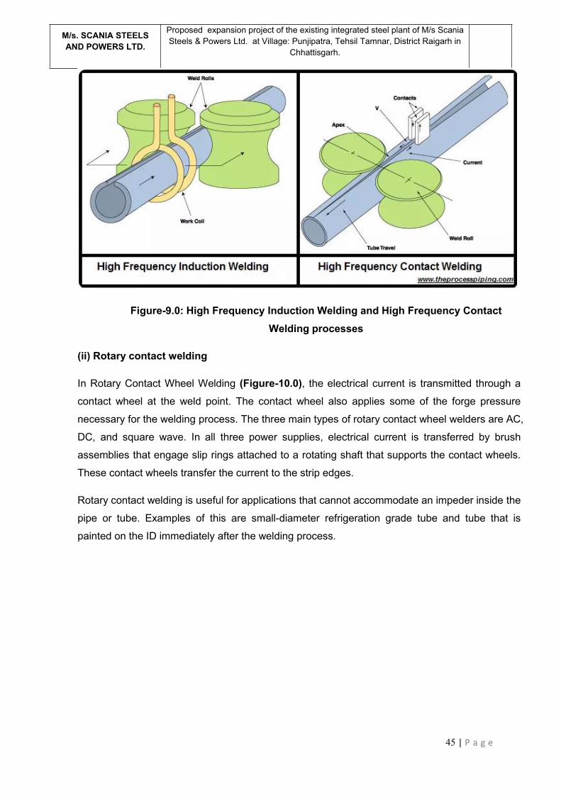
45 | P a g e
M/s. SCANIA STEELSAND POWERS LTD.
Proposed expansion project of the existing integrated steel plant of M/s ScaniaSteels & Powers Ltd. at Village: Punjipatra, Tehsil Tamnar, District Raigarh in
Chhattisgarh.
Figure-9.0: High Frequency Induction Welding and High Frequency ContactWelding processes
(ii) Rotary contact welding
In Rotary Contact Wheel Welding (Figure-10.0), the electrical current is transmitted through a
contact wheel at the weld point. The contact wheel also applies some of the forge pressure
necessary for the welding process. The three main types of rotary contact wheel welders are AC,
DC, and square wave. In all three power supplies, electrical current is transferred by brush
assemblies that engage slip rings attached to a rotating shaft that supports the contact wheels.
These contact wheels transfer the current to the strip edges.
Rotary contact welding is useful for applications that cannot accommodate an impeder inside the
pipe or tube. Examples of this are small-diameter refrigeration grade tube and tube that is
painted on the ID immediately after the welding process.

46 | P a g e
M/s. SCANIA STEELSAND POWERS LTD.
Proposed expansion project of the existing integrated steel plant of M/s ScaniaSteels & Powers Ltd. at Village: Punjipatra, Tehsil Tamnar, District Raigarh in
Chhattisgarh.
Figure-10.0: Rotary contact welding process
A few advantages to note with ERW pipe:
There are no fusion metals used during the manufacturing process. This means that the
pipe is extremely strong and durable.
The weld seam cannot be seen or felt. This is a major difference when looking at the
double submerged arc welding process, which creates an obvious welded bead that
might need to be eliminated.
With the advances in high-frequency electric currents for welding, the process is far
easier and safer.
The conventional ERW manufacturing procedures of steel pipes and tubes are shown in
Figure- 11.0
Figure 11.0 : Conventional electric resistance welding (ERW) manufacturing proceduresof the steel pipes and tubes.
47 | P a g e
M/s. SCANIA STEELSAND POWERS LTD.
Proposed expansion project of the existing integrated steel plant of M/s ScaniaSteels & Powers Ltd. at Village: Punjipatra, Tehsil Tamnar, District Raigarh in
Chhattisgarh.
8. PIPE GALVANIZING UNIT
M/s Scania Steels and Powers Ltd. Proposes to install a new pipe galvanization unit of 30,000
TPA capacity. Galvanized iron pipes are widely known for a wide range of practical applications
— water transportation, in agriculture, telecommunications, plumbing, and more. Galvanized iron
pipes are great to utilize because of its corrosion resistance and its durability for both indoor and
outdoor use. The process descriptions of galvanizing pipes are as follows:
Metal Preparation
Dipping Phase into Molten Zinc
Cooling, Finishing, and Drying
Metal Preparation
The iron pipes firstly go through a meticulous surface preparation. Typically, the process of the
surface preparation of galvanized iron pipes operates as follows:
Firstly, the steel is cleansed with the use of a caustic solution — a corrosive substance in
where it will completely remove all oil, grease, dirt, and excess pain.
After the caustic solution is rinsed off, the iron pipe is then pickled. Pickling is a metal
surface treatment that is used to eliminate stains, impurities, contaminants, rust, or scale from
ferrous metals.
The iron pipe is pickled in an acidic solution to get rid of the mill scale or also known as
the flaky surface of the hot-rolled steel.
After the pickling solution is rinsed off, the iron pipe will not proceed to fluxing. Commonly,
zinc ammonium chloride is used to the base metal to suppress oxidation of the cleaned surface.
Dipping Phase into Molten Zinc
Here, the iron pipes are generously immersed in a bath of molten zinc of around 449 degrees
Celsius. Here, it will alloy a thick and robust layer on the surface of the base metal.
Cooling, Finishing, and Drying
After the zinc dipping technique is done, it is now time for the galvanized iron pipes to cool down.
Typically, the galvanized iron pipes are cooled in a quench tank for it to cool down quickly and
restrain unwanted effects of the newly formed coating with the atmosphere of its surroundings.
9. CAPTIVE POWER PLANT
48 | P a g e
M/s. SCANIA STEELSAND POWERS LTD.
Proposed expansion project of the existing integrated steel plant of M/s ScaniaSteels & Powers Ltd. at Village: Punjipatra, Tehsil Tamnar, District Raigarh in
Chhattisgarh.
The company intends to set up a Captive Power Plant of 24 MW capacity (out of which 18 MW
will be based on WHRB and 6 MW will be AFBC boiler based) in addition to its 8 MW WHRB
based CPP (under implementation stage for which EC has already been granted). After the
implementation of the total project, the total electricity generation will be 32 MW.
The waste heat, generated from the DRI plant will be utilized in WHRBs for the production of 26
MW electricity. The dolo-char generated from the DRI plant along with coal will be utilized in the
proposed AFBC boiler for the production of 6 MW electricity.
Atmospheric Fluidized Bed Combustion (AFBC) technology has the potential to use
alternative fuel sources such as coal, wood, or waste, and is able to reduce and control nitrogen
oxide (NOx) and sulfur dioxide (SO2) emissions. In AFBC, coal is crushed to a size of 1 – 10 mm
depending on the rank of coal, type of fuel feed and fed into the combustion chamber. The
atmospheric air, which acts as both the fluidization air and combustion air, is delivered at a
pressure and flows through the bed after being preheated by the exhaust flue gases. The
velocity of fluidising air is in the range of 1.2 to 3.7 m /sec. The rate at which air is blown through
the bed determines the amount of fuel that can be reacted. Almost all AFBC/ bubbling bed
boilers use in-bed evaporator tubes in the bed of limestone, sand and fuel for extracting the heat
from the bed to maintain the bed temperature.
The bed depth is usually 0.9 m to 1.5 m deep and the pressure drop averages about 1 inch of
water per inch of bed depth. Very little material leaves the bubbling bed – only about 2 to 4 kg of
solids are recycled per ton of fuel burned. Typical fluidized bed combustors of this type is shown
in Figures 12 a.
The combustion gases pass over the super heater sections of the boiler, flow past the
economizer, the dust collectors and the air preheaters before being exhausted to atmosphere.
The main special feature of atmospheric fluidised bed combustion is the constraint imposed by
the relatively narrow temperature range within which the bed must be operated. With coal, there
is risk of clinker formation in the bed if the temperature exceeds 950oC and loss of combustion
efficiency if the temperature falls below 800oC. For efficient sulphur retention, the temperature
should be in the range of 800oC to 850oC.
AFBC boilers comprise of following systems:
a) Fuel feeding system
b) Air Distributor
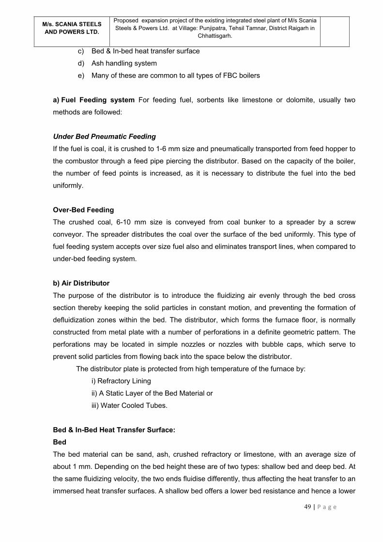
49 | P a g e
M/s. SCANIA STEELSAND POWERS LTD.
Proposed expansion project of the existing integrated steel plant of M/s ScaniaSteels & Powers Ltd. at Village: Punjipatra, Tehsil Tamnar, District Raigarh in
Chhattisgarh.
c) Bed & In-bed heat transfer surface
d) Ash handling system
e) Many of these are common to all types of FBC boilers
a) Fuel Feeding system For feeding fuel, sorbents like limestone or dolomite, usually two
methods are followed:
Under Bed Pneumatic FeedingIf the fuel is coal, it is crushed to 1-6 mm size and pneumatically transported from feed hopper to
the combustor through a feed pipe piercing the distributor. Based on the capacity of the boiler,
the number of feed points is increased, as it is necessary to distribute the fuel into the bed
uniformly.
Over-Bed FeedingThe crushed coal, 6-10 mm size is conveyed from coal bunker to a spreader by a screw
conveyor. The spreader distributes the coal over the surface of the bed uniformly. This type of
fuel feeding system accepts over size fuel also and eliminates transport lines, when compared to
under-bed feeding system.
b) Air DistributorThe purpose of the distributor is to introduce the fluidizing air evenly through the bed cross
section thereby keeping the solid particles in constant motion, and preventing the formation of
defluidization zones within the bed. The distributor, which forms the furnace floor, is normally
constructed from metal plate with a number of perforations in a definite geometric pattern. The
perforations may be located in simple nozzles or nozzles with bubble caps, which serve to
prevent solid particles from flowing back into the space below the distributor.
The distributor plate is protected from high temperature of the furnace by:
i) Refractory Lining
ii) A Static Layer of the Bed Material or
iii) Water Cooled Tubes.
Bed & In-Bed Heat Transfer Surface:BedThe bed material can be sand, ash, crushed refractory or limestone, with an average size of
about 1 mm. Depending on the bed height these are of two types: shallow bed and deep bed. At
the same fluidizing velocity, the two ends fluidise differently, thus affecting the heat transfer to an
immersed heat transfer surfaces. A shallow bed offers a lower bed resistance and hence a lower

50 | P a g e
M/s. SCANIA STEELSAND POWERS LTD.
Proposed expansion project of the existing integrated steel plant of M/s ScaniaSteels & Powers Ltd. at Village: Punjipatra, Tehsil Tamnar, District Raigarh in
Chhattisgarh.
pressure drop and lower fan power consumption. In the case of deep bed, the pressure drop is
more and this increases the effective gas velocity and also the fan power.
In-Bed Heat Transfer Surface
In a fluidized in-bed heat transfer process, it is necessary to transfer heat between the bed
material and an immersed surface, which could be that of a tube bundle, or a coil. The heat
exchanger orientation can be horizontal, vertical or inclined. From a pressure drop point of view,
a horizontal bundle in a shallow bed is more attractive than a vertical bundle in a deep bed. Also,
the heat transfer in the bed depends on number of parameters like (i) bed pressure (ii) bed
temperature (iii) superficial gas velocity (iv) particle size (v) Heat exchanger design and (vi) gas
distributor plate design.
Ash Handling SystemBottom ash removalBottom ash from proposed boiler will be carried through a submerged belt conveyor to silo. From
Silo it will be disposed to ash dump area in covered trucks in moistened condition.
Fly ash removalThe fly ash from the proposed boiler will be collected in economizer hoppers, air heater hoppers,
ESP hoppers and will be conveyed through dense phase pneumatic conveying system to silo.
The fly ash to be disposed from the silo will be moistened to reduce the dust while collecting the
ash. The system will be provided with telescopic chute and rotary feeder for loading the ash into
covered trucks.
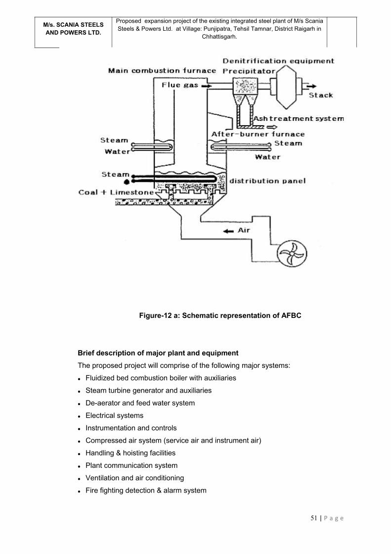
51 | P a g e
M/s. SCANIA STEELSAND POWERS LTD.
Proposed expansion project of the existing integrated steel plant of M/s ScaniaSteels & Powers Ltd. at Village: Punjipatra, Tehsil Tamnar, District Raigarh in
Chhattisgarh.
Figure-12 a: Schematic representation of AFBC
Brief description of major plant and equipmentThe proposed project will comprise of the following major systems:
Fluidized bed combustion boiler with auxiliaries
Steam turbine generator and auxiliaries
De-aerator and feed water system
Electrical systems
Instrumentation and controls
Compressed air system (service air and instrument air)
Handling & hoisting facilities
Plant communication system
Ventilation and air conditioning
Fire fighting detection & alarm system
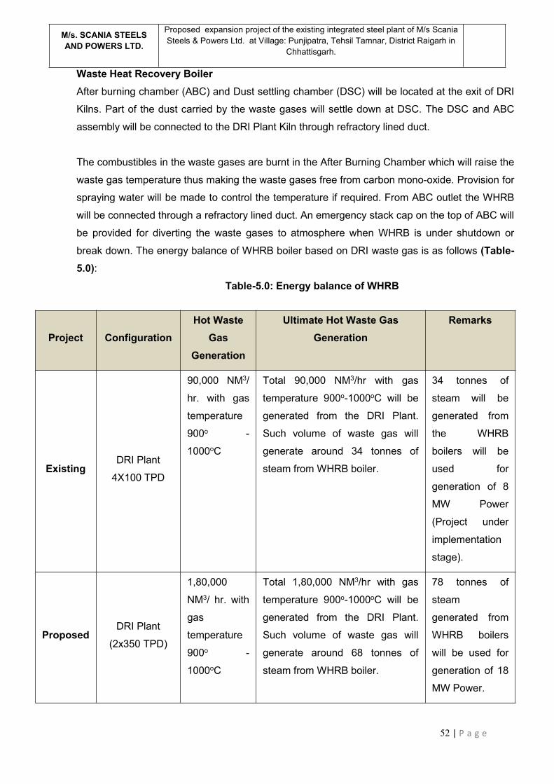
52 | P a g e
M/s. SCANIA STEELSAND POWERS LTD.
Proposed expansion project of the existing integrated steel plant of M/s ScaniaSteels & Powers Ltd. at Village: Punjipatra, Tehsil Tamnar, District Raigarh in
Chhattisgarh.
Waste Heat Recovery BoilerAfter burning chamber (ABC) and Dust settling chamber (DSC) will be located at the exit of DRI
Kilns. Part of the dust carried by the waste gases will settle down at DSC. The DSC and ABC
assembly will be connected to the DRI Plant Kiln through refractory lined duct.
The combustibles in the waste gases are burnt in the After Burning Chamber which will raise the
waste gas temperature thus making the waste gases free from carbon mono-oxide. Provision for
spraying water will be made to control the temperature if required. From ABC outlet the WHRB
will be connected through a refractory lined duct. An emergency stack cap on the top of ABC will
be provided for diverting the waste gases to atmosphere when WHRB is under shutdown or
break down. The energy balance of WHRB boiler based on DRI waste gas is as follows (Table-5.0):
Table-5.0: Energy balance of WHRB
Project ConfigurationHot Waste
GasGeneration
Ultimate Hot Waste GasGeneration
Remarks
ExistingDRI Plant
4X100 TPD
90,000 NM3/
hr. with gas
temperature
900o -
1000oC
Total 90,000 NM3/hr with gas
temperature 900o-1000oC will be
generated from the DRI Plant.
Such volume of waste gas will
generate around 34 tonnes of
steam from WHRB boiler.
34 tonnes of
steam will be
generated from
the WHRB
boilers will be
used for
generation of 8
MW Power
(Project under
implementation
stage).
ProposedDRI Plant
(2x350 TPD)
1,80,000
NM3/ hr. with
gas
temperature
900o -
1000oC
Total 1,80,000 NM3/hr with gas
temperature 900o-1000oC will be
generated from the DRI Plant.
Such volume of waste gas will
generate around 68 tonnes of
steam from WHRB boiler.
78 tonnes of
steam
generated from
WHRB boilers
will be used for
generation of 18
MW Power.

53 | P a g e
M/s. SCANIA STEELSAND POWERS LTD.
Proposed expansion project of the existing integrated steel plant of M/s ScaniaSteels & Powers Ltd. at Village: Punjipatra, Tehsil Tamnar, District Raigarh in
Chhattisgarh.
The boiler will be complete with evaporator steam drum, mud drum, bank of super heaters,
economizer, atemperator, air fans, ESP, internal piping etc. Soot blowing and super heater
atemperation system will be also provided. Boiler will be provided with blow down tanks (IBD,
CBD etc), sample cooler.
Flue gas cleaning systemThe exhaust gases will be discharged from boiler to ESP and then into the atmosphere through
Induced Draft fan and chimney. The pressure drop in the boiler ducts and ESP will be kept to
match with the requirement of ID fan. The boiler will be of semi out door type with a weather
canopy and side covering of trapeze corrugated steel sheets or other suitable materials as
available.
The gases flue gas having huge quantity of dust particles will pass out of the WHRB through one
multi-field Electrostatic Precipitator before escaping into the atmosphere through the stack. The
ESP will be installed between the WHRB and the stack. The dust content in gas down stream of
ESP shall be limited to 30 mg/Nm3. The ESP unit will be provided with transformers, rectifier and
controls. The dust particles will be collected below ESP in the hoppers and conveyed by means
of conveyors or pneumatically and stored in silos. The collected dust will be subsequently
disposed off by trucks. Figure-12 b shows the schematic diagram of WHRB based CPP.
(vi) Raw material required along with estimated quantity, likely source, marketing areaof final products, mode of transport of raw material and finished product.The major raw material, which will be handled, consists of Iron Ore fines / Lump, Coal,
dolomite, Limestone, bentonite etc. The annual requirement of major raw materials,
which will be required for the proposed project is presented below in Table 6.0.
PROCESS FLOW DIAGRAM – WASTE HEAT RECOVERY POWER PLANT
Figure-12 b: Schematic representation of WHRB

54 | P a g e
M/s. SCANIA STEELSAND POWERS LTD.
Proposed expansion project of the existing integrated steel plant of M/s ScaniaSteels & Powers Ltd. at Village: Punjipatra, Tehsil Tamnar, District Raigarh in
Chhattisgarh.
Table - 6.0 : Raw Material Requirement for the overall project
Sl.No
Units Rawmaterials
ExistingProject
Proposedproject
Totalrequirement
Source
1. Sponge IronPlant
Iron OrePellet
2,12,000 TPA 3,71,000 TPA 5,83,000 TPA In House
Coal 1,60,000 TPA 2,80,000 TPA 4,40,000 TPA Imported,Local Market
Dolomite 5,300 TPA 9,275 TPA 14,575 TPA Local Market
2. InductionFurnace
Sponge Iron 1,14,400 TPA 1,80,400 TPA 2,94,800 TPA In House
Pig Iron 24,000 TPA 32,725 TPA 56,725 TPA Local Market
Scrap 13,835 TPA 25,362 TPA 39,197TPA In House &Local Market
Ferro Alloys 975 TPA 1,534 TPA 2,509 TPA Local Market
3. Iron oreBeneficiationPlant
Iron ore fines - 37,40,000TPA 37,40,000 TPA Local Market
4. Pellet Plant Iron oreconcentrate
- 16,00,000 TPA 16,00,000 TPA In House
5 Gasifier Coal - 120000 TPA 120000 TPA Local Market
6 Strip RollingMill
Billet - 1,31,500 TPA 1,31,500 TPA In House
7 Re Rolling Mill Billet - 1,82,000 TPA 1,82,000 TPA In House
8 ERW PipeMfg. unit
Steel sheet - 1,30,000 TPA 1,30,000 TPA In House
9 Galvanisationunit
ERW Pipe - 30,000 TPA 30,000 TPA In House
10 Captive powerplant (AFBC)
Coal - 13,000 TPA 13,000 TPA Local Market
Dolochar - 1,10,000 TPA 1,10,000 TPA In House
Raw materials will be received at plant site by rail/road. All the trucks for raw material and
finished product transportation shall comply with the applicable environmental norms. The
Material-Cum-Process flow diagram for the proposed project has been depicted in
Figure-13 a & 13 b respectively.

55 | P a g e
M/s. SCANIA STEELSAND POWERS LTD.
Proposed expansion project of the existing integrated steel plant of M/s ScaniaSteels & Powers Ltd. at Village: Punjipatra, Tehsil Tamnar, District Raigarh in
Chhattisgarh.
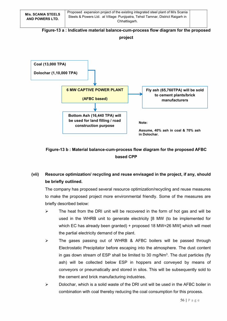
56 | P a g e
M/s. SCANIA STEELSAND POWERS LTD.
Proposed expansion project of the existing integrated steel plant of M/s ScaniaSteels & Powers Ltd. at Village: Punjipatra, Tehsil Tamnar, District Raigarh in
Chhattisgarh.
Figure-13 a : Indicative material balance-cum-process flow diagram for the proposedproject
Figure-13 b : Material balance-cum-process flow diagram for the proposed AFBCbased CPP
(vii) Resource optimization/ recycling and reuse envisaged in the project, if any, shouldbe briefly outlined.
The company has proposed several resource optimization/recycling and reuse measures
to make the proposed project more environmental friendly. Some of the measures are
briefly described below:
The heat from the DRI unit will be recovered in the form of hot gas and will be
used in the WHRB unit to generate electricity [8 MW (to be implemented for
which EC has already been granted) + proposed 18 MW=26 MW] which will meet
the partial electricity demand of the plant.
The gases passing out of WHRB & AFBC boilers will be passed through
Electrostatic Precipitator before escaping into the atmosphere. The dust content
in gas down stream of ESP shall be limited to 30 mg/Nm3. The dust particles (fly
ash) will be collected below ESP in hoppers and conveyed by means of
conveyors or pneumatically and stored in silos. This will be subsequently sold to
the cement and brick manufacturing industries.
Dolochar, which is a solid waste of the DRI unit will be used in the AFBC boiler in
combination with coal thereby reducing the coal consumption for this process.
Coal (13,000 TPA)
Dolochar (1,10,000 TPA)
6 MW CAPTIVE POWER PLANT
(AFBC based)
Fly ash (65,760TPA) will be soldto cement plants/brick
manufacturers
Bottom Ash (16,440 TPA) willbe used for land filling / road
construction purposeNote:
Assume, 40% ash in coal & 70% ashin Dolochar.
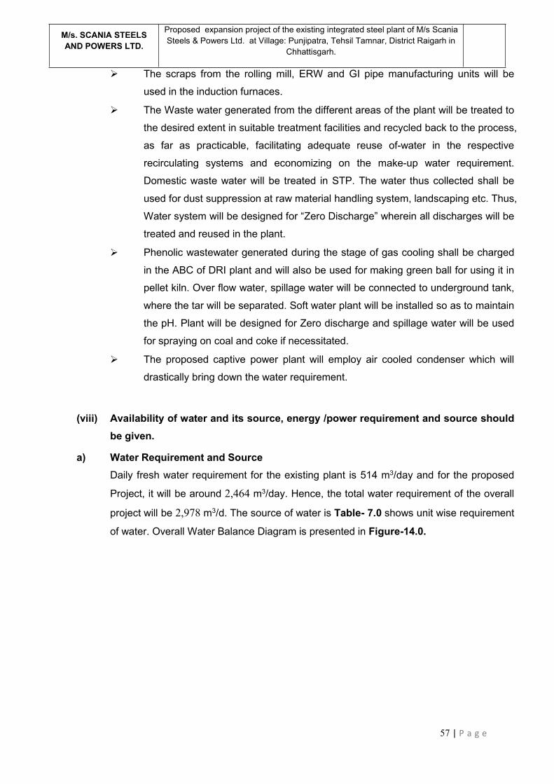
57 | P a g e
M/s. SCANIA STEELSAND POWERS LTD.
Proposed expansion project of the existing integrated steel plant of M/s ScaniaSteels & Powers Ltd. at Village: Punjipatra, Tehsil Tamnar, District Raigarh in
Chhattisgarh.
The scraps from the rolling mill, ERW and GI pipe manufacturing units will be
used in the induction furnaces.
The Waste water generated from the different areas of the plant will be treated to
the desired extent in suitable treatment facilities and recycled back to the process,
as far as practicable, facilitating adequate reuse of-water in the respective
recirculating systems and economizing on the make-up water requirement.
Domestic waste water will be treated in STP. The water thus collected shall be
used for dust suppression at raw material handling system, landscaping etc. Thus,
Water system will be designed for “Zero Discharge” wherein all discharges will be
treated and reused in the plant.
Phenolic wastewater generated during the stage of gas cooling shall be charged
in the ABC of DRI plant and will also be used for making green ball for using it in
pellet kiln. Over flow water, spillage water will be connected to underground tank,
where the tar will be separated. Soft water plant will be installed so as to maintain
the pH. Plant will be designed for Zero discharge and spillage water will be used
for spraying on coal and coke if necessitated.
The proposed captive power plant will employ air cooled condenser which will
drastically bring down the water requirement.
(viii) Availability of water and its source, energy /power requirement and source shouldbe given.
a) Water Requirement and SourceDaily fresh water requirement for the existing plant is 514 m3/day and for the proposed
Project, it will be around 2,464 m3/day. Hence, the total water requirement of the overall
project will be 2,978 m3/d. The source of water is Table- 7.0 shows unit wise requirement
of water. Overall Water Balance Diagram is presented in Figure-14.0.

58 | P a g e
M/s. SCANIA STEELSAND POWERS LTD.
Proposed expansion project of the existing integrated steel plant of M/s ScaniaSteels & Powers Ltd. at Village: Punjipatra, Tehsil Tamnar, District Raigarh in
Chhattisgarh.
Table - 7.0 : Unit wise Water Requirement Breakup
Sl.No.
Description Existing + To beimplemented(m3/day)
Proposed(m3/day)
1. Iron Ore Beneficiation Plant - 500
2. Pelletization Plant - 685
3. Producer Gas Plant - 120
4. DRI Unit 360 680
5. SMS with Caster 40 100
6. Strip Rolling Mill - 20
7. Re-Rolling Mill - 30
8. ERW pipe manufacturing unit - 5
9. Pipe galvanizing unit - 10
10. Captive Power Plant 96 270
11. Domestic demand 18 44
Total 514 2464

59 | P a g e
M/s. SCANIA STEELSAND POWERS LTD.
Proposed expansion project of the existing integrated steel plant of M/s ScaniaSteels & Powers Ltd. at Village: Punjipatra, Tehsil Tamnar, District Raigarh in
Chhattisgarh.
Figure-14.0 : Indicative water balance diagram
360
Evp. Loss (84)
12
72
5
Note: All units are in m3/d
Source: Bore Well
10
1
395
34
Proposed (2,464 m3/d)
Iron Ore Beneficiation(1X2.67 MTPA)
Evp. Loss (400)
100
Pellet plant(2X0.8 MTPA)
Evp. Loss (685)685
DRI(2X350 T)
Evp. Loss (544)
136 680
SMS(3X20 T)
Evp. Loss (80)
20 100
Strip Rolling mill(0.13 MTPA)
Evp. Loss (16)
4 20
Re Rolling mill(0.18 MTPA)
Evp. Loss (24)
6 30
ERW(0.1 MTPA)
Evp. Loss (4)
Domestic 44
Galvanizing unit(0.03 MTPA)
Evp. Loss (8)
2
500
CPP (18 MWWHRB+6MW AFBC)
Evp. Loss (236)
270
92
390
Wastewater
Process dustsuppression, ashhandling, floorcleaning, greenbelt development
etc
Treatmentfacility
5
303
48
Existing/Not yet implemented (514m3/d)
Evp. Loss (288)
40
Evp. Loss (32)
CPP(8 MWWHRB) *
96
SMS(1X6 +1X8 +2X15 T)
8
DRI (4X100 TPD)
Domestic
STP
1518
*8 MW WHRB has not beenimplemented for which EChas already been granted.
PGP 3x60000 +2X8000120
24 Evp loss (96)
35
60 | P a g e
M/s. SCANIA STEELSAND POWERS LTD.
Proposed expansion project of the existing integrated steel plant of M/s ScaniaSteels & Powers Ltd. at Village: Punjipatra, Tehsil Tamnar, District Raigarh in
Chhattisgarh.
b) Power Requirement and SourceThe estimated power requirement of the existing units is around 15 MW and that of the
proposed units is around 41 MW which will be sourced from the 32 MW capacity of
captive power plant & balance from the state grid. Unit wise power breakup for the
overall project has been presented in Table-8.0.
Table-8.0: Power requirement details for the overall projectSlNo
Description Existing/Notyet
implemented(MW)
Proposed(MW)
1. Pellet Plant - 6
2. Iron Ore Beneficiation Plant - 5
3. DRI Unit 1 2
4. SMS with Caster 13 18
5. Captive Power Plant 0.5 1.5
6. Strip & Re-Rolling Mill - 5
7. ERW pipe manufacturing unit - 2
8. Auxiliary & other loads 0.5 1.5
Total 15 41
(ix) Quantity of waste to be generated (liquid and solid) and scheme for theirmanagement/disposal
The pollutants in the form of solids, liquids and gases are expected to be generated from
various Units viz., Iron ore beneficiation and pelletization, Steel manufacturing and
Captive Power Plants. Release of such pollutants without proper care may affect the
environment adversely. Pollution of the environment not only adversely affects the
human beings, flora and fauna but also shortens the life of plant and equipment. This
vital aspect, therefore, has been taken into account while planning the plant and
equipment and adequate measures have been proposed to limit the emission of
pollutants within the stipulations of statutory norms.
Water Pollution Control
Process water to the tune of 395 m3/d generated from the overall project (existing
and the proposed units) will be treated to the desired extent in suitable treatment
facilities and recycled back to the process, as far as practicable, facilitating
adequate reuse of-water in the respective recirculating systems and economizing

61 | P a g e
M/s. SCANIA STEELSAND POWERS LTD.
Proposed expansion project of the existing integrated steel plant of M/s ScaniaSteels & Powers Ltd. at Village: Punjipatra, Tehsil Tamnar, District Raigarh in
Chhattisgarh.
on the make-up water requirement. Domestic waste water to the tune of 62 m3/d
generated from the overall project will be treated in STP. The water thus collected
shall be used for dust suppression at raw material handling system, greenery
purposes, ash handling etc. Thus, Water system will be designed for “Zero Liquid
Discharge” wherein all discharges will be treated and reused in the plant.
The proposed captive power plant will employ air cooled condenser, which will
drastically bring down the water requirement.
The Boiler blowdown will be controlled to maintain system solids loading within
normal limits for proper water chemistry. The effluent will have less than 100 ppm
suspended solids and will be led into the station sump mix with other station
effluents to reduce temperature and utilized for disposal of ash in slurry form.
Surface run-off will be settled in a settling basin prior to reuse/ disposal.
Treatment of waste water from Producer Gas Plant : Phenolic wastewater
generated during the stage of gas cooling shall be charged in the ABC of DRI
plant and will also be used for making green ball for using it in pellet kiln. Over
flow water, spillage water will be connected to underground tank, where the tar
will be settled. Soft water plant will be installed so as pH is maintained. Plant will
be designed for Zero discharge and spillage water will be used for spraying on
coal and coke if necessitated.
In Indirect Type Centrifugal Tar Separator, there is no direct contact of gas with
water. The cooling is done by heat transfer through wall to circulating water. Tar
is removed by centrifugal action without any washing with water. Therefore,
phenolic water is not generated in this method of tar separation and the
associated water pollution issues are completely eliminated.
Process water will be recycled in the system and over flow of the underground
tank will be reused /recycled for the water seals and secondary application in
gasifier plant. Occasional disposal of seal-water which would contain traces of
phenols would be incinerated in the after burning chambers of sponge iron kilns.
Treatment of waste water from Galvanizing Unit: The primary liquid waste is
spent pickling acid from the acid bath. The spent acid will be treated by
neutralization by using lime chips. After neutralization, iron oxide sludge will be
produced. After neutralization, the effluent will be stored in the sedimentation tank
after which the iron oxide sludge will pass through the filter press. The
supernatant liquid will be used for non-critical purposes like dust suppression etc.
inside the plant. The cake received from the filter press will be packed in polybags
62 | P a g e
M/s. SCANIA STEELSAND POWERS LTD.
Proposed expansion project of the existing integrated steel plant of M/s ScaniaSteels & Powers Ltd. at Village: Punjipatra, Tehsil Tamnar, District Raigarh in
Chhattisgarh.
and will be stored at a secluded and secured place inside the plant area for its
disposal through registered vendors. Hence, an Effluent Treatment Plant (ETP)
will be installed with the Galvanizing Unit.
Solid Waste Management
Solid wastes that will be generated from IFs are slag and dust. The hot slag
generated from IF will be transferred to slag yard after cooling. IF slag will be
used for road construction and land filling purposes after metal recovery in the
metal recovery plant.
Dolo-char from the DRI unit will be used in AFBC boiler.
Solid wastes that will be generated from SMS with continuous caster units are the
scales. The scales are collected from the drain and transferred to IF for reuse.
The solid wastes from the rolling mill are end cuts and miss rolls, which will be re-
used in induction furnace.
The fly ash generated from Captive Power Plant will be sold as a raw material for
cement plants and brick manufacturing. The bottom ash from CPP will be used as
land filling.
Tailing from I/O Beneficiation plant will be used for Brick manufacturing / Paver
block making / aggregate in concrete / road construction purpose. No tailing pond
has been proposed inside the plant premises.
Generated Tar from the proposed producer gas plant will be temporarily stored at
an isolated location inside the plant premises. Finally, it will be sold to authorized
re-processors
Solid & Hazardous waste generation and its disposal for the overall project are presented
in Table-9.0.

63 | P a g e
M/s. SCANIA STEELSAND POWERS LTD.
Proposed expansion project of the existing integrated steel plant of M/s ScaniaSteels & Powers Ltd. at Village: Punjipatra, Tehsil Tamnar, District Raigarh in
Chhattisgarh.
Table-9.0: Solid & Hazardous waste generation and its disposal from the overall project
Sl.No.
Type Existingproject(TPA)
Proposedproject(TPA)
Total(TPA)
Utilization
1. Tailings from I/OBeneficiation Plant
- 10,70,000 10,70,000 To be used for Brick manufacturing/ Paver block making / aggregate inconcrete / road constructionpurpose.
2. Dolo Char from DRIPlant
40,000 70,000 1,10,000 To be used in AFBC Boiler for powergeneration.
3. Slag & dust from SMS(IFs)
14,900 20,317 35,217 To be used for Land filling / RoadConstruction purpose / paver blockmaking after metal recovery.
4. Scale, end cuts etc.from SMS
6,497 4,765 11,262 To be used in Induction Furnaces.
5. Scale, end cuts etc.from SRM & RRM
- 3,500 3,500 To be used in Induction Furnaces.
6. Zinc Dross fromGalvanising unit
- 200 200 To be sold to the AuthorisedVenders
7. Fly Ash from AFBCBoiler
- 65,760 65,760 To be used as a raw material forcement and brick manufacturing.
8. Bottom Ash fromAFBC Boiler
- 16,440 16,440 To be used for land filling / roadconstruction purpose.
9. Tar sludge from PGP - 5,389 5,389 To be sold to the AuthorisedVenders
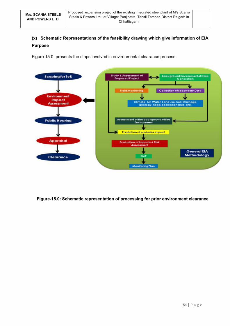
64 | P a g e
M/s. SCANIA STEELSAND POWERS LTD.
Proposed expansion project of the existing integrated steel plant of M/s ScaniaSteels & Powers Ltd. at Village: Punjipatra, Tehsil Tamnar, District Raigarh in
Chhattisgarh.
(x) Schematic Representations of the feasibility drawing which give information of EIAPurpose
Figure 15.0 presents the steps involved in environmental clearance process.
Figure-15.0: Schematic representation of processing for prior environment clearance

65 | P a g e
M/s. SCANIA STEELSAND POWERS LTD.
Proposed expansion project of the existing integrated steel plant of M/s ScaniaSteels & Powers Ltd. at Village: Punjipatra, Tehsil Tamnar, District Raigarh in
Chhattisgarh.
4.0 SITE ANALYSIS
(i) ConnectivityThe project site already has proper road linkage for transport of materials and equipment.
The nearest Railway Station is Bhupdeopur Railway Station, which is located about 14.2
km distance (aerially) at south-west direction from the project site. The distance of
Raigarh Railway station from the project site is about 20.5 km (aerially), located at ‘SSE’
direction w.r.t. the project site. NH-200 (Raipur, Bilaspur, Sarangarh, Raigarh, Deogarh,
Talcher and Chandikhol linking National Highway) is passing through Raigarh about 19
kms distance (aerial distance) at south direction from the project site. The nearest Airport
is Raipur Airport in Chhattisgarh i.e., known as Swami Vivekanand International Airport,
which is located at about 250 km (aerial distance) in west direction from the project site.
NH-200 connects the project site with the airport at Raigarh. The project site has good
connectivity with port of Vishakhapatnam.
(ii) Land form, Land use and Land ownershipThe proposed project will be located at Village: Punjipatra, Tehsil Tamnar, District
Raigarh in Chhattisgarh. The proposed units will be installed on the available land within
the existing plant premises of 23.4718 ha (58 acre) as well as on some additional land
[12.34291 ha (30.5 acre)], adjacent to the existing plant premises, thus comprising a total
land area of 35.81468 hectare (88.5 acres) at Village: Punjipatra, Tehsil Tamnar, District
Raigarh in Chhattisgarh. The additional land is vacant and industrial in nature. The
acquisition of this additional land is under process. The additional land is vacant and
industrial in nature.
The important river in the study area is Kelo River, which flows at a distance of 6.3 kms
at ESE direction from the project site. This river is a main tributary of River Mahanadi
which is the major important river in Chhattisgarh. Kurket River which is another
important river in the study area is flowing about 7.6 kms away at WNW direction from
the project site. The Rabo dam which is situated on the way of the Kurket River is
located about 7 kms distance at west direction from the project site. The project site is
around 73 m above Kurkut River bed and Robo dam and thus there is very less chance
of occurrence of flood in the project site. As per existing land used pattern, land is
generally flat and no major earth filling is required for the implementation of the proposed
project.
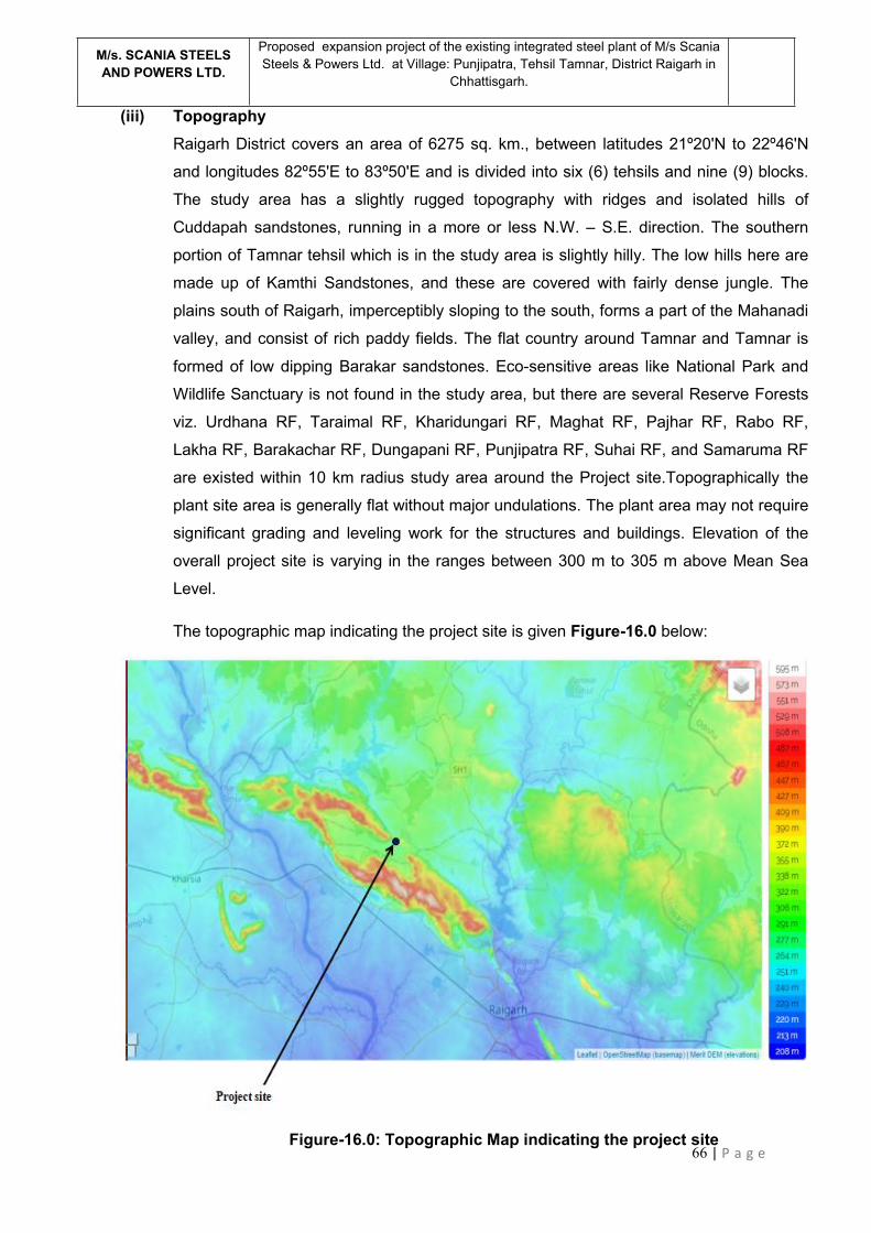
66 | P a g e
M/s. SCANIA STEELSAND POWERS LTD.
Proposed expansion project of the existing integrated steel plant of M/s ScaniaSteels & Powers Ltd. at Village: Punjipatra, Tehsil Tamnar, District Raigarh in
Chhattisgarh.
(iii) TopographyRaigarh District covers an area of 6275 sq. km., between latitudes 21º20'N to 22º46'N
and longitudes 82º55'E to 83º50'E and is divided into six (6) tehsils and nine (9) blocks.
The study area has a slightly rugged topography with ridges and isolated hills of
Cuddapah sandstones, running in a more or less N.W. – S.E. direction. The southern
portion of Tamnar tehsil which is in the study area is slightly hilly. The low hills here are
made up of Kamthi Sandstones, and these are covered with fairly dense jungle. The
plains south of Raigarh, imperceptibly sloping to the south, forms a part of the Mahanadi
valley, and consist of rich paddy fields. The flat country around Tamnar and Tamnar is
formed of low dipping Barakar sandstones. Eco-sensitive areas like National Park and
Wildlife Sanctuary is not found in the study area, but there are several Reserve Forests
viz. Urdhana RF, Taraimal RF, Kharidungari RF, Maghat RF, Pajhar RF, Rabo RF,
Lakha RF, Barakachar RF, Dungapani RF, Punjipatra RF, Suhai RF, and Samaruma RF
are existed within 10 km radius study area around the Project site.Topographically the
plant site area is generally flat without major undulations. The plant area may not require
significant grading and leveling work for the structures and buildings. Elevation of the
overall project site is varying in the ranges between 300 m to 305 m above Mean Sea
Level.
The topographic map indicating the project site is given Figure-16.0 below:
Figure-16.0: Topographic Map indicating the project site
67 | P a g e
M/s. SCANIA STEELSAND POWERS LTD.
Proposed expansion project of the existing integrated steel plant of M/s ScaniaSteels & Powers Ltd. at Village: Punjipatra, Tehsil Tamnar, District Raigarh in
Chhattisgarh.
(iii) Existing land use pattern (agriculture, non-agriculture, forest, water bodies (includingarea under CRZ), shortest distances from the periphery of the project to periphery of theforests, national park, wild life sanctuary, eco sensitive areas, water bodies (distance fromthe HFL of the river), CRZ. In case of notified industrial area, a copy of the Gazettenotification should be given
The existing environmental settings of the area has been presented in Table 10.0 below:
Table - 10.0: Environmental Settings of the Area
S.NO.
PARTICULARS
DETAILS
(with approximate aerial distance & direction from the nearest plant
boundary)
1. Existing landuse The proposed project will be located at Village: Punjipatra,
Tehsil Tamnar, District Raigarh in Chhattisgarh.
The proposed project will be installed on the available land
within the existing plant premises of 23.4718 ha (58 acre) as
well as on some additional land [12.34291 ha (30.5 acre)],
adjacent to the existing plant premises, thus comprising a total
land area of 35.81468 hectare (88.5 acres) at Village:
Punjipatra, Tehsil Tamnar, District Raigarh in Chhattisgarh. The
additional land is vacant and industrial in nature. The
acquisition of this additional land is under process.
The 10 km radius study area of the proposed project site is
largely surrounded by arable mono cropped land followed by
forest land. Patches of vacant waste land, rural settlements
along with industrial area are also present within the 10 km
radius of the project site.
2. National Parks, Wildlife
Sanctuaries, Biosphere
Reserves, within 10 km
radius
There is no National Park, Wildlife Sanctuary, Biosphere
Reserve located within 10 Km radius study area.
3. Reserved Forests (RF) /
Protected Forests (PF) within
10 km radius
Eco-sensitive areas like National Park and Wildlife Sanctuary is
not found in the study area, but there are several Reserve
Forests viz. Urdhana RF, Taraimal RF, Kharidungari RF,
Maghat RF, Pajhar RF, Rabo RF, Lakha RF, Barakachar RF,

68 | P a g e
M/s. SCANIA STEELSAND POWERS LTD.
Proposed expansion project of the existing integrated steel plant of M/s ScaniaSteels & Powers Ltd. at Village: Punjipatra, Tehsil Tamnar, District Raigarh in
Chhattisgarh.
S.NO.
PARTICULARS
DETAILS
(with approximate aerial distance & direction from the nearest plant
boundary)
Dungapani RF, Punjipatra RF, Suhai RF, and Samaruma RF
are existed within 10 km radius study area around the Project
site. There is an important Deep forest Jungle named
‘Samaruma Jungle’ which is situated at a nearest distance of
about 2 kms at north direction from the Project site.
4. Water Bodies (within 10 kmradius)
The important river in the study area is Kelo River which flows
at a distance of 6.3 kms at ESE direction from the project site.
This river is a main tributary of River Mahanadi which is the
major important river in Chhattisgarh. Kurket River which is
another important river in the study area is flowing about 7.6
kms away at WNW direction from the project site. The Rabo
dam which is situated on the way of the Kurket River is located
about 7 kms distance at west direction from the project site.
(v) Existing InfrastructureMost of the facilities are available for setting up of the proposed project such as
Electricity, Water, Transportation of raw materials and finished goods etc. Skilled and
unskilled workers are also easily available within the area.
Same will be extended in the proposed expansion also. For establishment and
successful operation of plant, it is imperative to ensure availability of the following
infrastructure:
Availability of raw coal & iron ore and its proximity to the plant to reduce cost oftransportation.
Road / Rail head connection so that the raw materials and products can be easilyand economically transported.
Availability of water.
Permanent and reliable source of power.
Adequate land for the plant, storage of raw material and products & disposal ofwaste material.
(vi) Soil classificationThe soils of Chhattisgarh vary considerably in the three agro-climatic zones. Though the
nomenclature is different, the types of the soils especially the physical properties are the
69 | P a g e
M/s. SCANIA STEELSAND POWERS LTD.
Proposed expansion project of the existing integrated steel plant of M/s ScaniaSteels & Powers Ltd. at Village: Punjipatra, Tehsil Tamnar, District Raigarh in
Chhattisgarh.
same. The different soils that exist in the three agroclimatic zones are presented in
Table-11.0.
Table-11.0: Soil classification of Chhattisgarh
Agroclimaticzone
Districts Soil Characteristics
Chhattisgarh
Plains
Raipur, Gariyabandh, Baloda Bazar,
Mahasamund, Dhamtari, Durg, Bemetra,
Balood, Rajnandgaon, Kabirdham, Bilaspur,
Mungeli, Korba, Janjgir and part of Kanker
district (Narharpur & Kanker block) along with
part of Raigarh district
Bhata (Lateritic)
Matasi (Sandy
loam)
Dorsa (Clay loam)
Kanhar (Clay)
Bastar
Plateau
Jagdalpur, Kondagaon, Dantewada, Bijapur,
Narayanpur and remaining part of Kanker
district.
Marhan (Coarse
sandy)
Tikra (Sandy)
Mal (Sandy loam)
Gabhar (Clay &
Clay loam)
Northern hills Surguja, Surajpur, Balrampur, Koriya and
Jashpurnagar and Dharamjaigarh Tehsil of
Raigarh district.
Hilly soils
Tikra
Goda chawar
Bahara
The soils of Raigarh district have a large variation. The red coloured residual soil are
derived from the lateritisation of shale and sandstones and the areas covered by such
type of soil is known as “Bhata”. The black coloured soils are locally known as “Kanhar”
similarly there are pale yellow sandy loamy soils which are locally known as “Matasi” and
“Dorsa‟.
Ground water profile of the project site and surroundingsThe comprehensive ground water monitoring study has been undertaken by M/S ScaniaSteels & Powers Limited in the year 2020 as a compliance of the terms and conditions
imposed by Central Ground Water Authority (CGWA) while awarding the NOC for
withdrawal of ground water for the project.

70 | P a g e
M/s. SCANIA STEELSAND POWERS LTD.
Proposed expansion project of the existing integrated steel plant of M/s ScaniaSteels & Powers Ltd. at Village: Punjipatra, Tehsil Tamnar, District Raigarh in
Chhattisgarh.
The broad objective of the study was to assess the impact of ground water abstraction
on ground water storage and its quality and to identify the potential areas that have
registered change in ground water levels and quality so as to plan appropriate measures.
An area of about 314 Sq. Km has been considered encompassing 10 km of radius
around the project site to study the impact of ground water withdrawal. The study was
conducted to understand the overall picture of ground water regime changes and storage
behavior due to continuous abstraction of ground water in the project area has been
analyzed for the period January 2010 to Nov 2020.
The analysis of data in general indicates that there is insignificant impact of ground water
withdrawal from the project area on the overall ground water regime of the area. The
depth to water level of May / June 2020, in area remains between 2.3 to 20.75 meters
below ground level in core and buffer zone. The pre-monsoon depth to water indicates
that water levels between 5 to 10 mbgl are observed in the Samaruma, Punjipathara and
Amlidih villages of core zone and 43% of villages of buffer zone. Water levels between
less than 5 mbgl are observed in the Tumidih, Jhingalpara villages of core zone and 57%
of villages of buffer zone. Deeper water levels of more than 10 mbgl are observed in the
all PZ within the core zone and at Tamnar villages of buffer zone. As such the deeper
water level of more than 10 mbgl has been observed in and around the project area and
also fall on the water divide.
The depth to water level of November 2020 in area remains between 2 to 21.4 meters
below ground level in core and buffer zone. The spatial distribution of post-monsoon
depth to water broadly follows similar pattern as of pre-monsoon water level. Water
levels between 3 to 5 mbgl are observed In the villages of core zone namely Samaruma,
Punjipathara and Amlidih and 71% of villages of buffer zone.
Water levels between less than 3 mbgl are observed in the Tumidih village of core zone
and 14 % of villages of buffer zone. Deeper water levels of more than 5 mbgl are
observed in the all PZ and Samaruma within the core zone and at Deogaon, Suhai &
Tamnar villages of buffer zone . As such the deeper water level of more than 5 mbgl has
been observed in and around the project area and also fall on the water divide. Water
level fluctuation in the study area varies from 0.0 to 5.0 meters. Lower range of water
level fluctuation is also observed along the river course followed by 1 to 2, 2 to 3,3 to 4
and > 4 m.
Overall, from the comparison of mean water levels of the year 2010 to 2019 with respect
to the years 2020, in pre-monsoon period, it is found that all the villages in core zone,
71 | P a g e
M/s. SCANIA STEELSAND POWERS LTD.
Proposed expansion project of the existing integrated steel plant of M/s ScaniaSteels & Powers Ltd. at Village: Punjipatra, Tehsil Tamnar, District Raigarh in
Chhattisgarh.
which are considered for analysis showing rising in the range of 0.2 to 5.61 m. and all of
the villages in buffer zone are showing rise in range of 1.17 to 6.15 m. In post-monsoon
period, it is found that all the villages in core zone, which are considered for analysis are
showing rise in the range of 0.46 to 3.51 m. except Jhingalpara, PZ1 and PZ2 village
which is showing decline in water level-0.16 to -0.65 m, 38% of the villages in buffer
zone are showing rise in range of 0.04 to 2.35 m while 62% villages are showing decline
in water level in the range of -0.04 to -1.74 m. The area showing falling trend more than
20 cm/yr are of considerable significance, which is attributed to increase in draft in
selective patches.
In conclusion, if the decline per year is more than 0.20 m then for the period of eleven
years it will be more than 2.2 m which is considered as significant but in the present
scenario all the villages of core zone and buffer zone considered for analysis shows
decline less than 2.2 m over the period of eleven years, so it is evident that there is a
marginal decline in water level trend in post-monsoon period over the period of eleven
years.
The analysis of the chemical data shows that, the quality of ground water in the area
(both core and buffer zone) is generally alkaline in nature. All major ions are within the
limits of Bureau of Indian Standards for drinking purposes and meet the quality
requirements of irrigation. Thus, ground water is suitable for irrigation, domestic as well
as drinking purposes and there is no remarkable change in chemical quality of ground
water in and around the area.
(vii) Climatic data from secondary sourcesThe meteorological data described in this section have been collected from the IMD
Station located at Raigarh, which deemed to be representative of the study area.
The climate of the project area is humid and tropical. It is characterised by a hot and dry
summer from March to May, a south-west monsoon or rainy season from June to
September, a pleasant post-monsoon or retreating monsoon from October to November
and a cool winter from December to February. Therefore, climatologically, four seasons
viz. summer (pre-monsoon), monsoon, post-monsoon and winter could be deciphered
comprising the following months:
Summer : March, April, May
Monsoon : June, July, August, and September
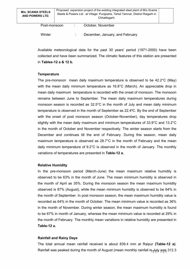
72 | P a g e
M/s. SCANIA STEELSAND POWERS LTD.
Proposed expansion project of the existing integrated steel plant of M/s ScaniaSteels & Powers Ltd. at Village: Punjipatra, Tehsil Tamnar, District Raigarh in
Chhattisgarh.
Post-monsoon : October, November
Winter : December, January, and February
Available meteorological data for the past 30 years’ period (1971-2000) have been
collected and have been summarized. The climatic features of this station are presented
in Tables-12 a & 12 b.
TemperatureThe pre-monsoon mean daily maximum temperature is observed to be 42.2°C (May)
with the mean daily minimum temperature as 16.8°C (March). An appreciable drop in
mean daily maximum temperature is recorded with the onset of monsoon. The monsoon
remains between June to September. The mean daily maximum temperatures during
monsoon season is recorded as 32.5°C in the month of July and mean daily minimum
temperature is observed in the month of September as 22.4⁰C. By the end of September
with the onset of post monsoon season (October-November), day temperatures drop
slightly with the mean daily maximum and minimum temperatures of 33.9°C and 13.2°C
in the month of October and November respectively. The winter season starts from the
December and continues till the end of February. During this season, mean daily
maximum temperature is observed as 28.7°C in the month of February and the mean
daily minimum temperature of 9.2°C is observed in the month of January. The monthly
variations of temperatures are presented in Table-12 a.
Relative HumidityIn the pre-monsoon period (March-June) the mean maximum relative humidity is
observed to be 63% in the month of June. The mean minimum humidity is observed in
the month of April as 35%. During the monsoon season the mean maximum humidity
observed is 87% (August), while the mean minimum humidity is observed to be 64% in
the month of September. In post monsoon season, the mean maximum humidity value is
recorded as 64% in the month of October. The mean minimum value is recorded as 36%
in the month of November. During winter season, the mean maximum humidity is found
to be 67% in month of January, whereas the mean minimum value is recorded at 29% in
the month of February. The monthly mean variations in relative humidity are presented in
Table-12 a.
Rainfall and Rainy DaysThe total annual mean rainfall received is about 839.4 mm at Raipur (Table-12 a).Rainfall was peaked during the month of August (mean monthly rainfall in July was 312.3
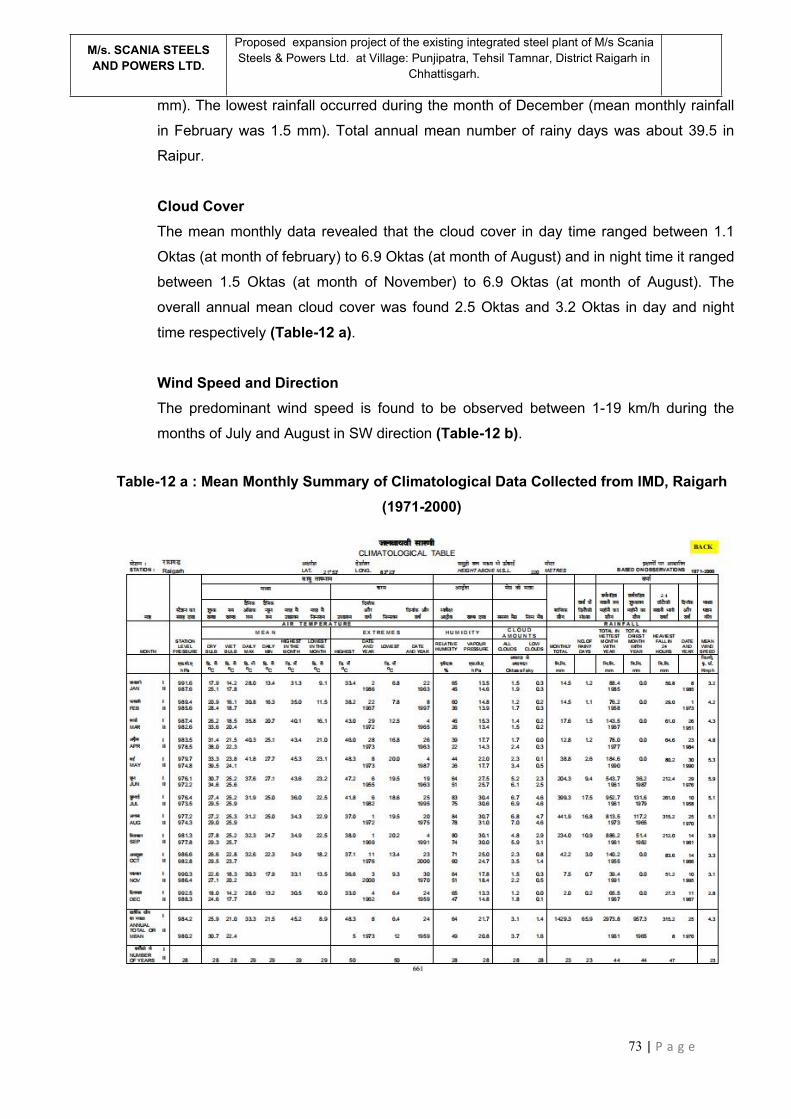
73 | P a g e
M/s. SCANIA STEELSAND POWERS LTD.
Proposed expansion project of the existing integrated steel plant of M/s ScaniaSteels & Powers Ltd. at Village: Punjipatra, Tehsil Tamnar, District Raigarh in
Chhattisgarh.
mm). The lowest rainfall occurred during the month of December (mean monthly rainfall
in February was 1.5 mm). Total annual mean number of rainy days was about 39.5 in
Raipur.
Cloud CoverThe mean monthly data revealed that the cloud cover in day time ranged between 1.1
Oktas (at month of february) to 6.9 Oktas (at month of August) and in night time it ranged
between 1.5 Oktas (at month of November) to 6.9 Oktas (at month of August). The
overall annual mean cloud cover was found 2.5 Oktas and 3.2 Oktas in day and night
time respectively (Table-12 a).
Wind Speed and DirectionThe predominant wind speed is found to be observed between 1-19 km/h during the
months of July and August in SW direction (Table-12 b).
Table-12 a : Mean Monthly Summary of Climatological Data Collected from IMD, Raigarh(1971-2000)
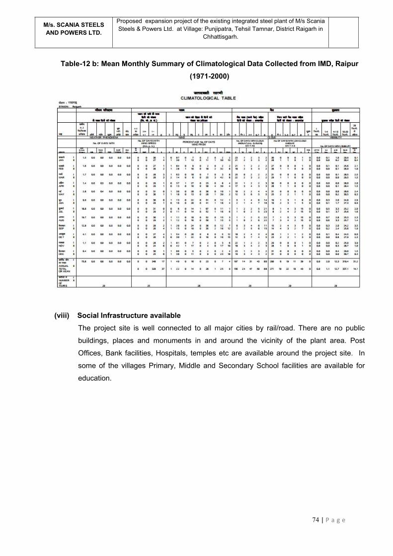
74 | P a g e
M/s. SCANIA STEELSAND POWERS LTD.
Proposed expansion project of the existing integrated steel plant of M/s ScaniaSteels & Powers Ltd. at Village: Punjipatra, Tehsil Tamnar, District Raigarh in
Chhattisgarh.
Table-12 b: Mean Monthly Summary of Climatological Data Collected from IMD, Raipur(1971-2000)
(viii) Social Infrastructure availableThe project site is well connected to all major cities by rail/road. There are no public
buildings, places and monuments in and around the vicinity of the plant area. Post
Offices, Bank facilities, Hospitals, temples etc are available around the project site. In
some of the villages Primary, Middle and Secondary School facilities are available for
education.
75 | P a g e
M/s. SCANIA STEELSAND POWERS LTD.
Proposed expansion project of the existing integrated steel plant of M/s ScaniaSteels & Powers Ltd. at Village: Punjipatra, Tehsil Tamnar, District Raigarh in
Chhattisgarh.
5.0 PLANNING BRIEF
(i) Planning Concept (type of industries, facilities, transportation etc.) Town andcountry Planning/ Development authority classification.Facilities required for the proposed project shall be provided as per requirement.
Transportation of raw material and final product will be done via existing road network.
Details of the road network inside the plant for movement of vehicles, materials,
auxiliaries and human resources have been provided in detailed plant layout.
(ii) Population Projection
Raigarh city is already a developed city and has well-developed infrastructure. As per
provisional reports of Census India, population of Raigarh in 2011 is 137,126; of which
male and female are 70,197 and 66,929 respectively. Although Raigarh city has
population of 137,126; its urban / metropolitan population is 150,019 of which 76,865 are
males and 73,154 are females
Most of the employment will be generated from the local areas only. The required
manpower for the proposed Plant can be classified into grades such as Executive,
Senior & Junior Managerial, Supervisory, High Skilled, Skilled, Semiskilled, Unskilled and
Staff. Such grading facilitates fixing of total emoluments in a few broad categories.
The Demographic and Socio economic characteristics with regards to demography,
literacy and occupational status will be describe in EIA report.
(iii) Land use planningThe proposed units will be installed on the available land within the existing plant
premises of 23.4718 ha (58 acre) as well as on some additional land [12.34291 ha (30.5
acre)], adjacent to the existing plant premises, thus comprising a total land area of
35.81468 hectare (88.5 acres) at Village: Punjipatra, Tehsil Tamnar, District Raigarh in
Chhattisgarh. The additional land is vacant and industrial in nature. The acquisition of
this additional land is under process.
In developing the plant general layout, expeditious movement of processing materials
must be considered. The factors, which have been taken into consideration, are
indicated below:

76 | P a g e
M/s. SCANIA STEELSAND POWERS LTD.
Proposed expansion project of the existing integrated steel plant of M/s ScaniaSteels & Powers Ltd. at Village: Punjipatra, Tehsil Tamnar, District Raigarh in
Chhattisgarh.
i. Economical & uninterrupted receipt of incoming raw materials & supplies; inter-
departmental dispatch of in process materials upto finishing stage and disposal of
plant wastes with minimum counter flow of materials particularly inside the shops.
ii. Logical locational arrangement of production units, plant services and ancillary
facilities to ensure minimum capital and operating costs both during the initial stage
and future expansion.
iii. Compactness of plant layout minimizing the distance of internal communications
and inter plant handling of processing materials without sacrificing operational
efficiency.
Table-13.0 shows the break-up of the land use of the project site/area:
Table -13.0: Land use break-up
(iv) Assessment of infrastructure demand (Physical & Social)
Raigarh city is a developed area with all sorts of infrastructure required to install any new
77 | P a g e
M/s. SCANIA STEELSAND POWERS LTD.
Proposed expansion project of the existing integrated steel plant of M/s ScaniaSteels & Powers Ltd. at Village: Punjipatra, Tehsil Tamnar, District Raigarh in
Chhattisgarh.
factory/plant. In the instant scenario, M/s Scania Steels and Powers Limited will have
no problem to supply the finished products in the nearby areas. To add further availability
of power, water and human resource (skilled and unskilled) will not pose any problem at
Raigarh. It may be prudent to mention that the project site is well connected by both rail
and surface transport with rest of India.
(v) Amenities/Facilities
To render necessary repair & maintenance, inventory, quality control related and
administrative services for the proposed project, following auxiliary facilities have already
been been provided inside the existing plant boundary which have been listed below:.
Repair and maintenance shop Stores Plant office Ancillary buildings
6.0 PROPOSED INFRASTRUCTURE
(i) Industrial Area (Processing Area)
For setting up of the Main Plant Facilities, Raw Material Storage, Water Storage
Reservoir, Auxiliary facilities, viz. Admn. Bldg., Tech. Bldg, Workshop, QC Lab, Switch
Yard, etc., 88.5 Acres of land shall be required. The company will use nearest road and
rail facility for goods transportation.
(ii) Residential area (Non-Processing area)The area around the site is under development with limited facilities.
Around 691 people will be engaged in the plant during operational stage of the proposed
project and nearby Raigarh city is close to the project site. Hence, no residential
colony/township is envisaged for employees.
(iii) Green Belt
In the existing plant area, there is significant presence of the greenbelt. Out of the total
plant area of 23.472 hectares (58 acres), the area covered under plantation is 7.85
hectares (19.4 acres). Hence, over 33% of the total plant area is covered under
plantation. Around 19500 plants/ trees are existing in the plant area.
The proposed project will be installed on the available land within the existing plant
premises of 23.4718 ha (58 acre) as well as on some additional land 12.34291 ha (30.5

78 | P a g e
M/s. SCANIA STEELSAND POWERS LTD.
Proposed expansion project of the existing integrated steel plant of M/s ScaniaSteels & Powers Ltd. at Village: Punjipatra, Tehsil Tamnar, District Raigarh in
Chhattisgarh.
acre), adjacent to the existing plant premises, thus comprising a total land area of
35.8168 hectare (88.5 acres). 33% of total of land will be developed as greenbelt.
Green belt development will further act as a traffic noise barrier. Green belt helps to
check soil erosion, makes the ecosystem more friendly and functionally more stable,
make the climate more conducive and restore water balance. Tree species shall be
selected considering tolerance to specific conditions or alternatively wide adaptability to
eco-physiological conditions. The tree species selected for green belt shall include the
native species like Butea Monosperma, Dalbergia Sissoo , Cassea Fistula,
Azadirachta Indica etc.
(iv) Social InfrastructureThe existing infrastructure facilities such as transportation, road networks, water
resource etc. are adequate at the project site. The social infrastructures like school,
college, temples and hospitals already exist in and around of this area. The above
infrastructure facilities need no further development for the project nor is any major
change in the infrastructure envisaged due to the project. Direct and indirect employment
generation is envisaged from the proposed project. Some glimpses of the developmental
activities are presented below:
Improving and building road network in the adjoining villages.
Strengthening School buildings with playgrounds.
Social awareness programme to improve the sanitation and hygiene, of the local
people.
The Proposed Project will set up training centre or tie up with Industrial Technical
Institutes to educate local youth as skilled labour.
(v) Connectivity (traffic and transportation road/rail/metro/water ways etc.)
The Site is well connected to Raigarh – Ambikapur Highway and same will be used for
transportation of Raw material, Product and Solid waste. Major raw material like Coal,
Iron ore etc. will be transported upto Raigarh Railway Station and from their by road (i.e.,
through Raigarh – Ambikapur Highway ) upto the plant.
(vi) Drinking Water Management
Existing domestic water requirement is 18 KLD and additional 44 KLD will be required for
the proposed expansion project. Thus, total domestic water requirement after proposed
expansion will be 62 KLD and the same will be sourced from bore well.
79 | P a g e
M/s. SCANIA STEELSAND POWERS LTD.
Proposed expansion project of the existing integrated steel plant of M/s ScaniaSteels & Powers Ltd. at Village: Punjipatra, Tehsil Tamnar, District Raigarh in
Chhattisgarh.
(vii) Sewerage System
Domestic waste water (50 m3/d) generated from office toilets, & canteen will be treated in
STP.
(viii) Industrial Waste management
For Air Environment
Plantation and Green belt development (33% of the plant area) have been taken
up all along the roads, plant premises etc.
Roads are/will be frequently sprinkled with water.
Adequate control measures like installation of Electrostatic Precipitator (ESP),
bag filters, dust suppression system, Dry Fog system and stacks of adequate
height at relevant points.
All the major stacks are/will be equipped with online continuous monitoring
system to ensure the desired efficiency of the respective control systems.
Most of the raw materials are being/will be stored under covered shed.
Regular maintenance of vehicles and machinery are being / will be carried out in
order to control emissions.
All bulk material carrying trucks are being/will be well covered with tarpaulin.
Facility for washing dust from wheels of incoming and outgoing trucks for the
proposed project through an water bath is/will be set up at the entrance of the
gate.
Transportation of materials is being / will be limited to day hours only.
For water environment
Waste water generated from the different areas of the plant will be treated to the
desired extent in suitable treatment facilities and recycled back to the process, as
far as practicable, facilitating adequate reuse of-water in the respective
recirculating systems and economizing on the make-up water requirement.
Domestic waste water will be treated in Sewage Treatment Plant. The water thus
collected shall be used for dust suppression at raw material handling system,
landscaping etc. Thus, Water system will be designed for “Zero Discharge”
wherein all discharges will be treated and reused in the plant.
The proposed captive power plant will employ air cooled condenser which will
drastically bring down the water requirement.
The Boiler blowdown will be controlled to maintain system solids loading within
normal limits for proper water chemistry. The effluent will have less than 100 ppm
80 | P a g e
M/s. SCANIA STEELSAND POWERS LTD.
Proposed expansion project of the existing integrated steel plant of M/s ScaniaSteels & Powers Ltd. at Village: Punjipatra, Tehsil Tamnar, District Raigarh in
Chhattisgarh.
suspended solids and will be led into the station sump mix with other station
effluents to reduce temperature and utilized for disposal of ash in slurry form.
Surface run-off will be settled in a settling basin prior to reuse/ disposal.
Treatment of waste water from Galvanizing Unit: The primary liquid waste is spent pickling
acid from the acid bath. The spent acid will be treated by neutralization by using lime chips.
After neutralization, iron oxide sludge will be produced. After neutralization, the effluent will be
stored in the sedimentation tank after which the iron oxide sludge will pass through the filter
press. The supernatant liquid will be used for non-critical purposes like dust suppression etc.
inside the plant. The cake received from the filter press will be packed in polybags and will be
stored at a secluded and secured place inside the plant area for its disposal through registered
vendors.
(ix) Solid Waste Management
Solid wastes that will be generated from IF are slag and dust. The hot slag
generated from IF will be transferred to slag yard after cooling. IF slag will be
used for road construction and land filling purposes after metal recovery in the
metal recovery plant.
Dolo-char from the DRI unit will be used in AFBC boiler.
Solid wastes that will be generated from SMS with continuous caster units are the
scales. The scales are collected from the drain and transferred to IF for reuse.
The solid wastes from the rolling mill are end cuts and miss rolls, which will be re
used in induction furnace.
The fly ash generated from Captive Power Plant will be sold as a raw material for
cement plants and brick manufacturing. The bottom ash from CPP will be used as
land filling.
Tailing from I/O Beneficiation plant will be used for Brick manufacturing / Paver
block making, aggregate in concrete, road construction purpose. No tailing pond
has been proposed inside the plant premises.
7.0 REHABILITATION AND RESETTLEMENT (R & R) PLAN
As such there is no requirement of R&R plan since no evacuation / ejection of habitation
will take place. The entire project area is industrial in nature and there is no habitation.
So there will not be displacement of any person.
81 | P a g e
M/s. SCANIA STEELSAND POWERS LTD.
Proposed expansion project of the existing integrated steel plant of M/s ScaniaSteels & Powers Ltd. at Village: Punjipatra, Tehsil Tamnar, District Raigarh in
Chhattisgarh.
8.0 PROJECT SCHEDULE AND COST ESTIMATES
(i) Likely date of start of construction and likely date of completionThe installation of several production units along with utilities and services will involve
award of all contracts, procurement of plant and equipment, construction & erection and
supervision of all activities at plant site.
The factors which are responsible for timely implementation of the project are:
Arrangement of proper finance for the project.
Finalization of layout of the proposed plant.
Design of utilities and services.
Placement of orders for plant and machinery.
Arrangements for Govt. sanctions and supply of power.
Recruitment of personnel.
As per an initial estimate, around 36 months will be needed for implementation of the
proposed project.
(ii) Estimated project cost along with analysis in term of economic viability of the projectThe Total cost of the Project will be around Rs. 629 Crores. The details of cost are given
below in Table 15.0 below :
Table-15.0: Cost breakup of the proposed project
SlNo.
Particulars Total Value inCrores
1 Pelletization Plant 180
2 Coal gasifier and Pulverizer Unit 6
3 Iron Ore Beneficiation Plant 60
4 DRI Unit 75
5 SMS with Caster 50
6 Captive Power Plant 168
7 Strip Rolling Mill 50
8 ERW pipe manufacturing unit 25
9 Pipe galvanizing unit 05
10 Admin Office, Store, Land
Security & Street Light, Boundary Wall,
Heavy Vehicles
20
11 Green Belt 2
Total 641
82 | P a g e
M/s. SCANIA STEELSAND POWERS LTD.
Proposed expansion project of the existing integrated steel plant of M/s ScaniaSteels & Powers Ltd. at Village: Punjipatra, Tehsil Tamnar, District Raigarh in
Chhattisgarh.
9.0 ANALYSIS OF PROPOSAL
(i) Financial and social benefits with special emphasis on the benefit to the localpeople including tribal population, if any, in the areaThe focus of proposed project is cost reduction by producing quality material as per the
required specification. There will be complete integration right from the beginning to
finished products. The estimated cost of the project is expected to be around Rs. 641
Crores. There will be substantial savings due to the said project as company will also be
eligible for various incentives. The total project is expected to be commissioned over a
period of 36 months in phased manner. The benefit from the projects planned will start
accruing from year one only. Besides, there will be immense social benefits of the
project, to the backward region.
Improvements in the Physical Infrastructure
The plant will result in considerable growth of service sector & infrastructure
development.
Supporting infrastructures as roads, rail power supply etc. already exist at the site.
Improvements in the Social Infrastructure
No environmental significant impacts are envisaged due to ancillary developments.
Mitigative measures will be proposed for management of anticipated impacts;
Community development activities will be initiated under CER programs;
Revenue to the exchequer in the form of power tariff and taxes etc; and
Opportunity for industrial development in the state.
Employment
It is estimated that the total requirement of manpower during operational phase will be
691. There will be much larger indirect employment in transport, ancillary, support
facilities and growth in local trades and business.
Related Documents