Progress in flexible and drapable reflective cholesteric displays Asad Khan Irina Shiyanovskaya Tod Schneider Erica Montbach Donald J. Davis Nick Miller Duane Marhefka Todd Ernst Forrest Nicholson J. William Doane Abstract — Recent results from encapsulation work on the development of flexible and drapable cholesteric liquid-crystal displays (LCDs) on substrates such as thin plastics, fabrics, and even paper will be presented. The approaches used to create flexible displays using single- and dual-substrate methods based on printable emulsions and polymerization-induced phase-separation (PIPS) tech- niques will be discussed. Keywords — Display, reflective, bistable, flexible, LCD. 1 Introduction Bistable reflective cholesteric displays 1,2 (ChLCDs) have been the subject of tremendous development and optimiza- tion programs. They are appearing in consumer devices and other electronics. More recently, the development of flexible cholesteric displays on thin plastic substrates have received much attention. 3 Indeed, cholesteric displays have even been fabricated by using only a single substrate. 4,5 Flexible and conformable displays bring with them the promise of greater design freedom for various products, from hand- held instruments to large-area signage. As such, their devel- opment and market introduction have been keenly observed matters. Flexible displays are therefore a focus of much research and development efforts at Kent Displays. Recent advances in polymerization-induced phase separation (PIPS) and emulsion-based flexible cholesteric displays will be described. Fabrication techniques for both approaches will also be reviewed. Advances in the PIPS approach include ultra-thin substrates, higher brightness, and higher contrast. The focus remains on developing prod- ucts for inclusion into the marketplace in late 2006. Advances in emulsion-based displays include coated dis- plays that can be lifted off and laminated on virtually any substrate and/or surface. Coated displays on photovoltaic cells, paper, and other fabrics have also been demonstrated. 2 Liquid-crystal encapsulation Encapsulation is utilized in creating flexible cholesteric dis- plays in order to prevent liquid-crystal (LC) flow under dis- play flexing. To create flexible cholesteric displays with dual- and single-substrate approaches, two different encap- sulation techniques were used: emulsification and polymeri- zation-induced phase separation. The key difference between the phase-separation approach and the emulsion approach can be understood by examining the method of liquid-crystalline droplet formation. In phase separation, the LC/pre-polymer mixture is laminated between two sub- strates and then LC droplets are created via polymerization- induced phase separation. In the emulsification approach, LC droplets are first created via emulsification and then the mixture is coated on a single substrate. This difference in encapsulation techniques inherent to each method allows for different display-design approaches. The two-substrate phase-separation approach is currently in product develop- ment, whereas the single-substrate or substrate-free emul- sion approaches are in the active research phase. These approaches and related applications will be discussed here in detail. 3 Dual-substrate flexible displays: Encapsulation using polymerization-induced phase separation The phase-separation approach is at a high level of maturity and is presently being developed for various products. Fig- ure 1 shows a photograph of a flexible display (240 × 160 EVGA) made using this approach on thin plastic substrates showing 16 gray levels and high multiplexing using a simple passive drive scheme. This EVGA will be used in various applications such as security tags, etc. The ability to demon- strate 4-bit gray levels allows for high-resolution graphics on 100 dpi as well as the anti-aliasing of fonts. The phase-separation method involves laminating a homogeneous single-phase mixture of pre-polymer materi- als (acrylate chemistries) and liquid crystal between two flexible substrates. The pre-polymer is only about 20% by weight of mixture. The space between the substrates is maintained by spherical plastic spacers dispersed in the pre- polymer/LC mixture. This is then exposed to low-intensity UV radiation. The UV radiation starts polymerizing the monomer materials, which in turn phase separates from the liquid crystal. Small droplets are created bounded on two Revised extended version of a paper presented at the 2006 SID Symposium held June 6–9, 2006 in San Francisco, California. The authors are with Kent Displays, Inc., 343 Portage Blvd., Kent, OH 44240; telephone 330/673-8784, fax -4408, e-mail: [email protected]. © Copyright 2007 Society for Information Display 1071-0922/07/1501-0009$1.00 Journal of the SID 15/1, 2007 9

Welcome message from author
This document is posted to help you gain knowledge. Please leave a comment to let me know what you think about it! Share it to your friends and learn new things together.
Transcript
Progress in flexible and drapable reflective cholesteric displays
Asad KhanIrina ShiyanovskayaTod SchneiderErica MontbachDonald J. DavisNick MillerDuane MarhefkaTodd ErnstForrest NicholsonJ. William Doane
Abstract — Recent results from encapsulation work on the development of flexible and drapablecholesteric liquid-crystal displays (LCDs) on substrates such as thin plastics, fabrics, and even paperwill be presented. The approaches used to create flexible displays using single- and dual-substratemethods based on printable emulsions and polymerization-induced phase-separation (PIPS) tech-niques will be discussed.
Keywords — Display, reflective, bistable, flexible, LCD.
1 IntroductionBistable reflective cholesteric displays1,2 (ChLCDs) havebeen the subject of tremendous development and optimiza-tion programs. They are appearing in consumer devices andother electronics. More recently, the development of flexiblecholesteric displays on thin plastic substrates have receivedmuch attention.3 Indeed, cholesteric displays have evenbeen fabricated by using only a single substrate.4,5 Flexibleand conformable displays bring with them the promise ofgreater design freedom for various products, from hand-held instruments to large-area signage. As such, their devel-opment and market introduction have been keenly observedmatters. Flexible displays are therefore a focus of muchresearch and development efforts at Kent Displays.
Recent advances in polymerization-induced phaseseparation (PIPS) and emulsion-based flexible cholestericdisplays will be described. Fabrication techniques for bothapproaches will also be reviewed. Advances in the PIPSapproach include ultra-thin substrates, higher brightness,and higher contrast. The focus remains on developing prod-ucts for inclusion into the marketplace in late 2006.Advances in emulsion-based displays include coated dis-plays that can be lifted off and laminated on virtually anysubstrate and/or surface. Coated displays on photovoltaiccells, paper, and other fabrics have also been demonstrated.
2 Liquid-crystal encapsulationEncapsulation is utilized in creating flexible cholesteric dis-plays in order to prevent liquid-crystal (LC) flow under dis-play flexing. To create flexible cholesteric displays withdual- and single-substrate approaches, two different encap-sulation techniques were used: emulsification and polymeri-zation-induced phase separation. The key differencebetween the phase-separation approach and the emulsionapproach can be understood by examining the method of
liquid-crystalline droplet formation. In phase separation,the LC/pre-polymer mixture is laminated between two sub-strates and then LC droplets are created via polymerization-induced phase separation. In the emulsification approach,LC droplets are first created via emulsification and then themixture is coated on a single substrate. This difference inencapsulation techniques inherent to each method allowsfor different display-design approaches. The two-substratephase-separation approach is currently in product develop-ment, whereas the single-substrate or substrate-free emul-sion approaches are in the active research phase. Theseapproaches and related applications will be discussed herein detail.
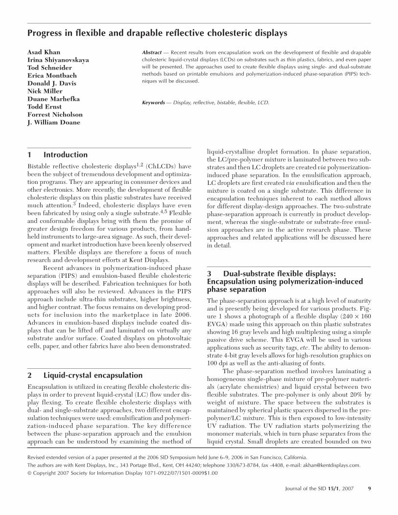
3 Dual-substrate flexible displays:Encapsulation using polymerization-inducedphase separationThe phase-separation approach is at a high level of maturityand is presently being developed for various products. Fig-ure 1 shows a photograph of a flexible display (240 × 160EVGA) made using this approach on thin plastic substratesshowing 16 gray levels and high multiplexing using a simplepassive drive scheme. This EVGA will be used in variousapplications such as security tags, etc. The ability to demon-strate 4-bit gray levels allows for high-resolution graphics on100 dpi as well as the anti-aliasing of fonts.
The phase-separation method involves laminating ahomogeneous single-phase mixture of pre-polymer materi-als (acrylate chemistries) and liquid crystal between twoflexible substrates. The pre-polymer is only about 20% byweight of mixture. The space between the substrates ismaintained by spherical plastic spacers dispersed in the pre-polymer/LC mixture. This is then exposed to low-intensityUV radiation. The UV radiation starts polymerizing themonomer materials, which in turn phase separates from theliquid crystal. Small droplets are created bounded on two
Revised extended version of a paper presented at the 2006 SID Symposium held June 6–9, 2006 in San Francisco, California.
The authors are with Kent Displays, Inc., 343 Portage Blvd., Kent, OH 44240; telephone 330/673-8784, fax -4408, e-mail: [email protected].
© Copyright 2007 Society for Information Display 1071-0922/07/1501-0009$1.00
Journal of the SID 15/1, 2007 9
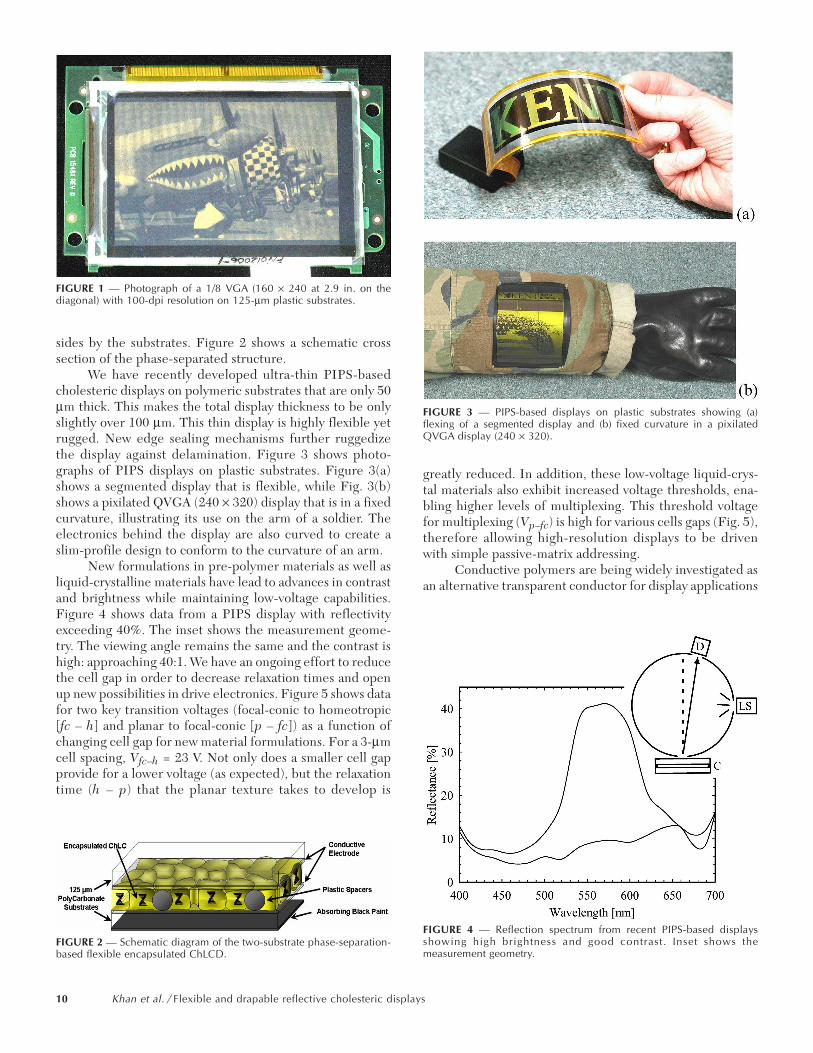
sides by the substrates. Figure 2 shows a schematic crosssection of the phase-separated structure.
We have recently developed ultra-thin PIPS-basedcholesteric displays on polymeric substrates that are only 50µm thick. This makes the total display thickness to be onlyslightly over 100 µm. This thin display is highly flexible yetrugged. New edge sealing mechanisms further ruggedizethe display against delamination. Figure 3 shows photo-graphs of PIPS displays on plastic substrates. Figure 3(a)shows a segmented display that is flexible, while Fig. 3(b)shows a pixilated QVGA (240 × 320) display that is in a fixedcurvature, illustrating its use on the arm of a soldier. Theelectronics behind the display are also curved to create aslim-profile design to conform to the curvature of an arm.
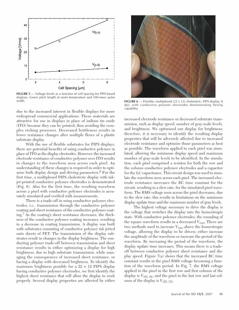
New formulations in pre-polymer materials as well asliquid-crystalline materials have lead to advances in contrastand brightness while maintaining low-voltage capabilities.Figure 4 shows data from a PIPS display with reflectivityexceeding 40%. The inset shows the measurement geome-try. The viewing angle remains the same and the contrast ishigh: approaching 40:1. We have an ongoing effort to reducethe cell gap in order to decrease relaxation times and openup new possibilities in drive electronics. Figure 5 shows datafor two key transition voltages (focal-conic to homeotropic[fc – h] and planar to focal-conic [p – fc]) as a function ofchanging cell gap for new material formulations. For a 3-µmcell spacing, Vfc–h = 23 V. Not only does a smaller cell gapprovide for a lower voltage (as expected), but the relaxationtime (h – p) that the planar texture takes to develop is
greatly reduced. In addition, these low-voltage liquid-crys-tal materials also exhibit increased voltage thresholds, ena-bling higher levels of multiplexing. This threshold voltagefor multiplexing (Vp–fc) is high for various cells gaps (Fig. 5),therefore allowing high-resolution displays to be drivenwith simple passive-matrix addressing.
Conductive polymers are being widely investigated asan alternative transparent conductor for display applications
FIGURE 1 — Photograph of a 1/8 VGA (160 × 240 at 2.9 in. on thediagonal) with 100-dpi resolution on 125-µm plastic substrates.
FIGURE 2 — Schematic diagram of the two-substrate phase-separation-based flexible encapsulated ChLCD.
FIGURE 3 — PIPS-based displays on plastic substrates showing (a)flexing of a segmented display and (b) fixed curvature in a pixilatedQVGA display (240 × 320).
FIGURE 4 — Reflection spectrum from recent PIPS-based displaysshowing high brightness and good contrast. Inset shows themeasurement geometry.
10 Khan et al. / Flexible and drapable reflective cholesteric displays
due to the increased interest in flexible displays for morewidespread commercial applications. These materials areattractive for use in displays in place of indium tin oxide(ITO) because they can be printed, thus avoiding the com-plex etching processes. Decreased brittleness results infewer resistance changes after multiple flexes of a plasticsubstrate display.
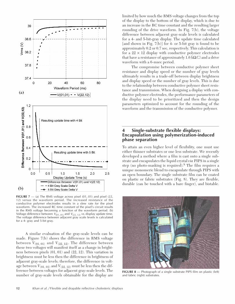
With the use of flexible substrates for PIPS displays,there are potential benefits of using conductive polymer inplace of ITO as the display electrodes. However, the increasedelectrode resistance of conductive polymer over ITO resultsin changes to the waveform seen across each pixel. Anunderstanding of these changes is required in order to opti-mize both display design and driving parameters.6 For thefirst time, a multiplexed PIPS cholesteric display with ink-jet-printed conductive polymer electrodes is demonstrated(Fig. 6). Also for the first time, the resulting waveformacross a pixel with conductive polymer electrodes is accu-rately simulated and verified with measurements.
There is a trade-off in using conductive polymer elec-trodes, i.e., transmission through the conductive polymercoating and sheet resistance of the conductive polymer coat-ing.7 As the coating’s sheet resistance decreases, the thick-ness of the conductive polymer coating increases, resultingin a decrease in coating transmission. A display was builtwith substrates consisting of conductive polymer ink jettedonto sheets of PET. The transmission of the display sub-strates result in changes in the display brightness. The con-ducting polymer trade-off between transmission and sheetresistance results in either optimizing a display for highbrightness, due to high substrate transmission, while man-aging the consequences of increased sheet resistance, orhaving a display with decreased brightness. To identify themaximum brightness possible for a 22 × 12 PIPS displayhaving conductive polymer electrodes, we first identify thehighest sheet resistance that will allow the display to workproperly. Several display properties are affected by either
increased electrode resistance or decreased substrate trans-mission, such as display speed, number of gray-scale levels,and brightness. We optimized our display for brightness;therefore, it is necessary to identify the resulting displayproperties that will be adversely affected due to increasedelectrode resistance and optimize those parameters as bestas possible. The waveform applied to each pixel was simu-lated, allowing the minimum display speed and maximumnumber of gray-scale levels to be identified. In the simula-tion, each pixel comprised a resistor for both the row andthe column conductive polymer electrodes and a capacitorfor the LC capacitance. This circuit design was used to simu-late the waveform seen across each pixel. The increased elec-trode resistance increases the RC time constant for thecircuit, resulting in a slew rate, for the simulated pixel wave-form. The RMS voltage seen across the pixel decreases, dueto the slew rate; this results in limitations on the minimumdisplay update time and the maximum number of gray levels.
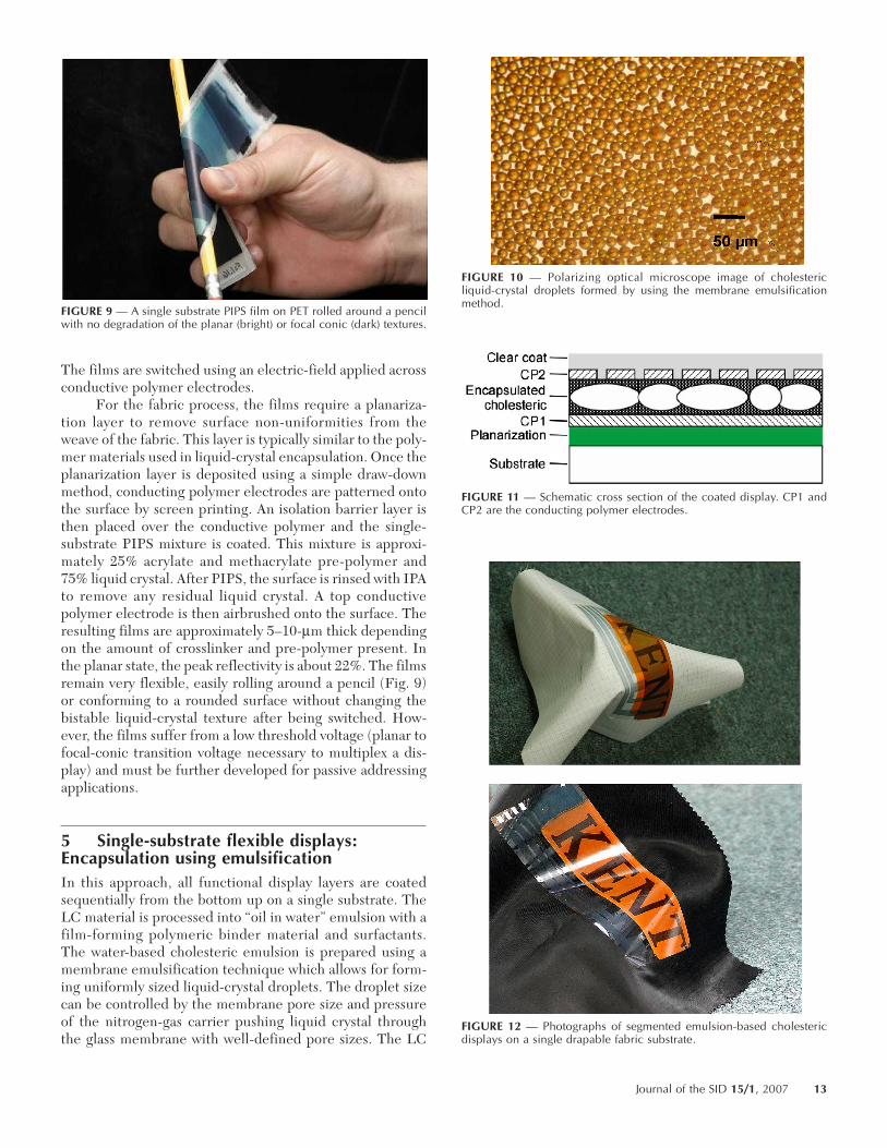
The highest voltage necessary to drive the display isthe voltage that switches the display into the homeotropicstate. With conductive polymer electrodes, the rounding ofthe square waveform results in a decreased Vrms. There aretwo methods used to increase Vrms above the homeotropicvoltage, allowing the display to be driven; either increasethe amplitude of the waveform or increase the period of thewaveform. By increasing the period of the waveform, thedisplay update time increases. This means there is a trade-off between conductive polymer sheet resistance and dis-play speed. Figure 7(a) shows that the increased RC timeconstant results in the pixel RMS voltage becoming a func-tion of the waveform period. In Fig. 7, the RMS voltageapplied to the pixel in the first row and first column of thedisplay is V(01, 01) and the pixel in the last row and last col-umn of the display is V(22, 12).
FIGURE 5 — Voltage levels as a function of cell spacing for PIPS-baseddisplays. Green pitch length at room temperature and 100-msec pulsewidth. FIGURE 6 — Flexible, multiplexed (22 × 12) cholesteric, PIPS display, 8
dpi, with conductive polymer electrodes demonstrating flexingcapability.
Journal of the SID 15/1, 2007 11
A similar evaluation of the gray-scale levels can bemade. Figure 7(b) shows the difference in RMS voltagebetween V(01, 01) and V(22, 12). The difference betweenthese two voltages will manifest itself as a change in bright-ness between pixels (01, 01) and (22, 12). This variation inbrightness must be less then the difference in brightness ofadjacent gray-scale levels; therefore, the difference in volt-age between V(01, 01) and V(22, 12) must be less then the dif-ference between voltages for adjacent gray-scale levels. Thenumber of gray-scale levels obtainable for the display are
limited by how much the RMS voltage changes from the topof the display to the bottom of the display, which is due toan increase in the RC time constant and the resulting largerrounding of the drive waveform. In Fig. 7(b), the voltagedifference between adjacent gray-scale levels is calculatedfor a 4- and 5-bit-gray display. The update time calculated[and shown in Fig. 7(b)] for 4- or 5-bit gray is found to beapproximately 0.2 or 0.7 sec, respectively. This calculation isfor a 22 × 12 display with conductive polymer electrodesthat have a resistance of approximately 1.6 kΩ/ and a drivewaveform with a 6-msec period.
The compromise between conductive polymer sheetresistance and display speed or the number of gray levelsultimately results in a trade-off between display brightnessand display speed or the number of gray levels. This is dueto the relationship between conductive polymer sheet resis-tance and transmission. When designing a display with con-ductive polymer electrodes, the performance parameters ofthe display need to be prioritized and then the designparameters optimized to account for the rounding of thewaveform and the transmission of the conductive polymer.
4 Single-substrate flexible displays:Encapsulation using polymerization-inducedphase separation
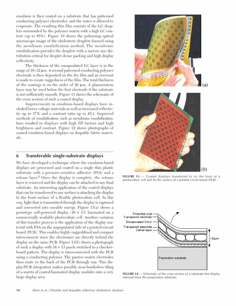
To attain an even higher level of flexibility, one must useeither thinner substrates or one less substrate. We recentlydeveloped a method where a film is cast onto a single sub-strate and encapsulates the liquid crystal via PIPS in a singlestep (no photo-masking is required).8 The film requires aunique monomeric blend to encapsulate through PIPS withan open boundary. The single substrate film can be coatedon plastic or fabric substrates (Fig. 8). They are flexible,durable (can be touched with a bare finger), and bistable.
FIGURE 7 — (a) The RMS voltage across pixel (01, 01) and pixel (22,12) versus the waveform period. The increased resistance of theconductive polymer electrodes results in a slew rate for the pixelwaveform. The increased RC time constant of the pixel’s circuit resultsin the RMS voltage becoming a function of the waveform period. (b)Voltage difference between V(01, 01) and V(22, 12) vs. display update time.The voltage difference between adjacent gray scale levels is calculatedfor a 4- gray and 5-bit gray.
FIGURE 8 — Photograph of a single substrate PIPS film on plastic (left)and fabric (right) substrates.
12 Khan et al. / Flexible and drapable reflective cholesteric displays
The films are switched using an electric-field applied acrossconductive polymer electrodes.
For the fabric process, the films require a planariza-tion layer to remove surface non-uniformities from theweave of the fabric. This layer is typically similar to the poly-mer materials used in liquid-crystal encapsulation. Once theplanarization layer is deposited using a simple draw-downmethod, conducting polymer electrodes are patterned ontothe surface by screen printing. An isolation barrier layer isthen placed over the conductive polymer and the single-substrate PIPS mixture is coated. This mixture is approxi-mately 25% acrylate and methacrylate pre-polymer and75% liquid crystal. After PIPS, the surface is rinsed with IPAto remove any residual liquid crystal. A top conductivepolymer electrode is then airbrushed onto the surface. Theresulting films are approximately 5–10-µm thick dependingon the amount of crosslinker and pre-polymer present. Inthe planar state, the peak reflectivity is about 22%. The filmsremain very flexible, easily rolling around a pencil (Fig. 9)or conforming to a rounded surface without changing thebistable liquid-crystal texture after being switched. How-ever, the films suffer from a low threshold voltage (planar tofocal-conic transition voltage necessary to multiplex a dis-play) and must be further developed for passive addressingapplications.
5 Single-substrate flexible displays:Encapsulation using emulsificationIn this approach, all functional display layers are coatedsequentially from the bottom up on a single substrate. TheLC material is processed into “oil in water” emulsion with afilm-forming polymeric binder material and surfactants.The water-based cholesteric emulsion is prepared using amembrane emulsification technique which allows for form-ing uniformly sized liquid-crystal droplets. The droplet sizecan be controlled by the membrane pore size and pressureof the nitrogen-gas carrier pushing liquid crystal throughthe glass membrane with well-defined pore sizes. The LC
FIGURE 9 — A single substrate PIPS film on PET rolled around a pencilwith no degradation of the planar (bright) or focal conic (dark) textures.
FIGURE 10 — Polarizing optical microscope image of cholestericliquid-crystal droplets formed by using the membrane emulsificationmethod.
FIGURE 11 — Schematic cross section of the coated display. CP1 andCP2 are the conducting polymer electrodes.
FIGURE 12 — Photographs of segmented emulsion-based cholestericdisplays on a single drapable fabric substrate.
Journal of the SID 15/1, 2007 13
emulsion is then coated on a substrate that has patternedconducting polymer electrodes, and the water is allowed toevaporate. The resulting thin film consists of the LC drop-lets surrounded by the polymer matrix with a high LC con-tent (up to 85%). Figure 10 shows the polarizing opticalmicroscope image of the cholesteric droplets formed usingthe membrane emulsification method, The membraneemulsification provides the droplets with a narrow size dis-tribution critical for droplet dense packing and high displayreflectivity.
The thickness of the encapsulated LC layer is in therange of 10–12 µm. A second patterned conducting polymerelectrode is then deposited on the dry film and an overcoatis made to create ruggedness of the film. The total thicknessof the coatings is on the order of 20 µm. A planarizationlayer may be used below the first electrode if the substrateis not sufficiently smooth. Figure 11 shows the schematic ofthe cross section of such a coated display.
Improvements in emulsion-based displays have in-cluded lower voltage materials as well as increased reflectiv-ity up to 37% and a contrast ratio up to 45:1. Improvedmethods of emulsification, such as membrane emulsification,have resulted in displays with high fill factors and highbrightness and contrast. Figure 12 shows photographs ofcoated emulsion-based displays on drapable fabric materi-als.
6 Transferable single-substrate displaysWe have developed a technique where the emulsion-baseddisplays are processed and coated on a single thin plasticsubstrate with a pressure-sensitive adhesive (PSA) and arelease layer.9 Once the display is complete, the releaselayer is removed and the display can be attached to any finalsubstrate. An interesting application of the coated displaysthat can be transferred to any surface is attaching the displayto the front surface of a flexible photovoltaic cell. In thisway, light that is transmitted through the display is capturedand converted into useable energy. Figure 13(a) shows aprototype self-powered display (16 × 13) laminated on acommercially available photovoltaic cell. Another variationof this transfer process is the application of the display ma-terial with PSA on the unpopulated side of a printed-circuitboard (PCB). This enables highly ruggeddized and compactinterconnects since the electronics are directly behind thedisplay on the same PCB. Figure 13(b) shows a photographof such a display with 16 × 13 pixels switched to a checker-board pattern. The display is interconnected with the PCBusing a conducting polymer. The passive-matrix electrodesthen route to the back of the PCB through vias. This dis-play/PCB integration makes possible near-borderless tilingof a matrix of coated/laminated display modules into a verylarge display area.
FIGURE 13 — Coated displays transferred to (a) the front of aphotovoltaic cell and (b) the surface of a printed circuit board (PCB).
FIGURE 14 — Schematic of the cross section of a substrate-free displayreleased from the preparation substrate.
14 Khan et al. / Flexible and drapable reflective cholesteric displays
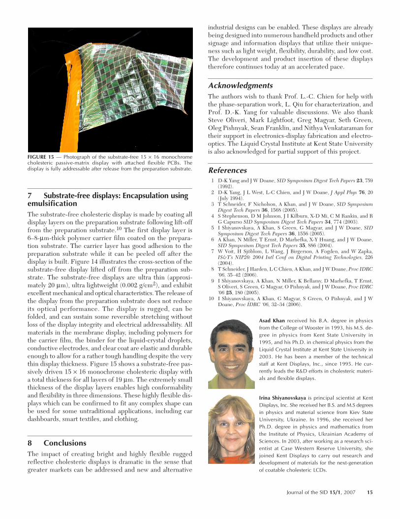
7 Substrate-free displays: Encapsulation usingemulsificationThe substrate-free cholesteric display is made by coating alldisplay layers on the preparation substrate following lift-offfrom the preparation substrate.10 The first display layer is6–8-µm-thick polymer carrier film coated on the prepara-tion substrate. The carrier layer has good adhesion to thepreparation substrate while it can be peeled off after thedisplay is built. Figure 14 illustrates the cross-section of thesubstrate-free display lifted off from the preparation sub-strate. The substrate-free displays are ultra thin (approxi-mately 20 µm), ultra lightweight (0.002 g/cm2), and exhibitexcellent mechanical and optical characteristics. The release ofthe display from the preparation substrate does not reduceits optical performance. The display is rugged, can befolded, and can sustain some reversible stretching withoutloss of the display integrity and electrical addressability. Allmaterials in the membrane display, including polymers forthe carrier film, the binder for the liquid-crystal droplets,conductive electrodes, and clear coat are elastic and durableenough to allow for a rather tough handling despite the verythin display thickness. Figure 15 shows a substrate-free pas-sively driven 15 × 16 monochrome cholesteric display witha total thickness for all layers of 19 µm. The extremely smallthickness of the display layers enables high conformabilityand flexibility in three dimensions. These highly flexible dis-plays which can be confirmed to fit any complex shape canbe used for some untraditional applications, including cardashboards, smart textiles, and clothing.
8 ConclusionsThe impact of creating bright and highly flexible ruggedreflective cholesteric displays is dramatic in the sense thatgreater markets can be addressed and new and alternative
industrial designs can be enabled. These displays are alreadybeing designed into numerous handheld products and othersignage and information displays that utilize their unique-ness such as light weight, flexibility, durability, and low cost.The development and product insertion of these displaystherefore continues today at an accelerated pace.
AcknowledgmentsThe authors wish to thank Prof. L.-C. Chien for help withthe phase-separation work, L. Qiu for characterization, andProf. D.-K. Yang for valuable discussions. We also thankSteve Oliveri, Mark Lightfoot, Greg Magyar, Seth Green,Oleg Pishnyak, Sean Franklin, and Nithya Venkataraman fortheir support in electronics-display fabrication and electro-optics. The Liquid Crystal Institute at Kent State Universityis also acknowledged for partial support of this project.
References1 D-K Yang and J W Doane, SID Symposium Digest Tech Papers 23, 759
(1992).2 D-K Yang, J L West, L-C Chien, and J W Doane, J Appl Phys 76, 20
(July 1994).3 T Schneider, F Nicholson, A Khan, and J W Doane, SID Symposium
Digest Tech Papers 36, 1568 (2005).4 S Stephenson, D M Johnson, J I Kilburn, X-D Mi, C M Rankin, and R
G Capurso SID Symposium Digest Tech Papers 34, 774 (2003).5 I Shiyanovskaya, A Khan, S Green, G Magyar, and J W Doane, SID
Symposium Digest Tech Papers 36, 1556 (2005).6 A Khan, N Miller, T Ernst, D Marhefka, X-Y Huang, and J W Doane,
SID Symposium Digest Tech Papers 35, 886 (2004).7 W Voit, H Sjöblom, L Wang, J Birgerson, A Fogden, and W Zapka,
IS&T’s NIP20: 2004 Intl Conf on Digital Printing Technologies, 226(2004).
8 T Schneider, J Harden, L C Chien, A Khan, and J W Doane, Proc IDRC‘06, 35–42 (2006).
9 I Shiyanovskaya, A Khan, N Miller, K Bellamy, D Marhefka, T Ernst,S Oliveri, S Green, G Magyar, O Pishnyak, and J W Doane, Proc IDRC‘06 25, 180 (2005).
10 I Shiyanovskaya, A Khan, G Magyar, S Green, O Pishnyak, and J WDoane, Proc IDRC ‘06, 32–34 (2006).
Asad Khan received his B.A. degree in physicsfrom the College of Wooster in 1993, his M.S. de-gree in physics from Kent State University in1995, and his Ph.D. in chemical physics from theLiquid Crystal Institute at Kent State University in2003. He has been a member of the technicalstaff at Kent Displays, Inc., since 1995. He cur-rently leads the R&D efforts in cholesteric materi-als and flexible displays.
Irina Shiyanovskaya is principal scientist at KentDisplays, Inc. She received her B.S. and M.S degreesin physics and material science from Kiev StateUniversity, Ukraine. In 1996, she received herPh.D. degree in physics and mathematics fromthe Institute of Physics, Ukrainian Academy ofSciences. In 2003, after working as a research sci-entist at Case Western Reserve University, shejoined Kent Displays to carry out research anddevelopment of materials for the next-generationof coatable cholesteric LCDs.
FIGURE 15 — Photograph of the substrate-free 15 × 16 monochromecholesteric passive-matrix display with attached flexible PCBs. Thedisplay is fully addressable after release from the preparation substrate.
Journal of the SID 15/1, 2007 15
Bill Doane received his Ph.D. in physics from theUniversity of Missouri in 1965. He is a co-founderof Kent Displays, Inc., and currently serves parttime as Chief Technology Officer. He is DirectorEmeritus of the Liquid Crystal Institute at KentState Unversity.
Duane Marhefka received his Ph.D. degree fromthe Department of Electrical Engineering at TheOhio State University, Columbus, Ohio in 2000.His current interest is drive waveforms forcholesteric LCDs. He is a member of the Societyfor Information Display and the IEEE.
Tod Schneider received his B.S. degree in physicsfrom Clarion University of Pennsylvania and hisPh.D. degree in chemical physics from the LiquidCrystal Institute of Kent State University. He is aSenior Scientist at Kent Displays and is currentlyworking on encapsulating cholesteric liquid crys-tals for flexible-display applications.
Donald Davis received his B.A. degree in physicsfrom the Thiel College in 1987 and his M.S. degreein physics from Oklahoma State University in1989. He was member of the technical staff atKent Displays, Inc., from 1996 to 2000 and returnedin late 2005. He currently leads the flexible-dis-play manufacturing efforts.
Erica Montbach is a Senior Scientist at Kent Dis-plays, Inc., and is responsible for flexible-displaydevelopment and innovation. She has severaltechnical publications and patents in different areasof liquid-crystal research. She has a B.A. degreein physics from The College of Wooster, an M.S.degree in physics from Colorado State University,and a Ph.D. degree in chemical physics from theLiquid Crystal Institute at Kent State University.
Forrest Nicholson received his B.A. degree inchemistry from Kent State University. He is SeniorProcess Engineer and has been working on fabri-cation processes at Kent Displays since 2000.
Todd Ernst is a Senior Electronics Engineer at KentDisplays and he is currently working on choles-teric display product design, driving circuitry, andcontrol. He received his B.S. degree in electricalengineering from Ohio State University. He haseight years of experience working in the liquid-crystal industry and is the author of numeroustechnical publications in liquid crystals. He has apatent on a gray-scale driving schemes. He is amember of the Society for Information Displayand IEEE.
Nick Miller is an electrical design engineer atKent Displays, specializing in the commercializa-tion of cholesteric LCDs with an emphasis on dis-play driving and system integration. Prior tojoining Kent Displays, he was a display engineerat the Liquid Crystal Institute at Kent State Univer-sity, providing electronics support for proprietarydrive schemes for LCDs. He received his B.S. degreein electrical engineering from the University ofAkron.
16 Khan et al. / Flexible and drapable reflective cholesteric displays
Related Documents

![4.1: Rollable Reflective Multicolor Cholesteric Displayslcd.creol.ucf.edu/publications/2006/IDRC Xianyu 4_1.pdf · in various applications such as reflection display [1, 2, 3], ...](https://static.cupdf.com/doc/110x72/5ad930307f8b9a86378ba916/41-rollable-reflective-multicolor-cholesteric-xianyu-41pdfin-various-applications.jpg)

![High performance liquid crystals for vehicle displaysfor liquid-crystal-on-silicon (LCOS) reflective projection displays (e.g. HUD and wearable displays) [9], since it exhibits high](https://static.cupdf.com/doc/110x72/6119fbf42279e26e9c7f3d70/high-performance-liquid-crystals-for-vehicle-displays-for-liquid-crystal-on-silicon.jpg)