*23567252_0917* Drive Technology \ Drive Automation \ System Integration \ Services Product Manual Safety-Related Subsystem MOVISAFE ® prog. FSSS-HC/HW-POS-DCS Edition 09/2017 23567252/EN

Welcome message from author
This document is posted to help you gain knowledge. Please leave a comment to let me know what you think about it! Share it to your friends and learn new things together.
Transcript
*23567252_0917*Drive Technology \ Drive Automation \ System Integration \ Services
Product Manual
Safety-Related SubsystemMOVISAFE® prog. FSSS-HC/HW-POS-DCS
Edition 09/2017 23567252/EN
SEW-EURODRIVE—Driving the world
Table of contents
Product Manual – MOVISAFE® prog. FSSS-HC/HW-POS-DCS 3
Table of contents1 System description .................................................................................................................. 5
1.1 Other applicable documentation ..................................................................................... 51.2 General description......................................................................................................... 51.3 System overview of the safety-related subsystem.......................................................... 5
1.3.1 Designated use .............................................................................................. 61.3.2 Predictable misuse......................................................................................... 71.3.3 Electrical interface (connection cable) ........................................................... 8
1.4 Scope of delivery ............................................................................................................ 81.4.1 Without hardware components ...................................................................... 81.4.2 With hardware components ........................................................................... 8
1.5 Declaration of conformity ................................................................................................ 9
2 Technical data......................................................................................................................... 102.1 Applied standards and directives .................................................................................. 102.2 Characteristic safety values of the safety-related subsystem....................................... 11
3 Software................................................................................................................................... 123.1 Structure of function block SEW303-PXV..................................................................... 12
3.1.1 Inputs and outputs........................................................................................ 123.1.2 Additional information................................................................................... 143.1.3 Sensor status ............................................................................................... 153.1.4 Sensor warning ............................................................................................ 153.1.5 Error messages............................................................................................ 163.1.6 Global variables ........................................................................................... 19
4 Configuration .......................................................................................................................... 204.1 Nameplate..................................................................................................................... 204.2 Reliability diagram......................................................................................................... 214.3 Ambient conditions of the safety-related subsystem..................................................... 21
4.3.1 Electromagnetic compatibility....................................................................... 224.4 Maximum response time of the safety-related subsystem............................................ 224.5 Error response functions............................................................................................... 23
4.5.1 Application software ..................................................................................... 234.5.2 Firmware ...................................................................................................... 23
4.6 Safety-related positioning accuracy .............................................................................. 244.7 Limits of the PXV..A data matrix positioning system..................................................... 25
4.7.1 Usage limits.................................................................................................. 254.7.2 Reading distance and alignment.................................................................. 254.7.3 Painted background ..................................................................................... 254.7.4 External light limits ....................................................................................... 254.7.5 Fatigue strength of mechanical holding fixture and guide............................ 254.7.6 Connection lead ........................................................................................... 264.7.7 No second identical lighting unit................................................................... 264.7.8 No code tape gaps ....................................................................................... 264.7.9 Component assembly .................................................................................. 264.7.10 Testing during startup .................................................................................. 2623
5672
52/E
N –
09/
2017
Table of contents
Product Manual – MOVISAFE® prog. FSSS-HC/HW-POS-DCS4
4.7.11 Configuration management.......................................................................... 274.7.12 Probability of dangerous transmission error................................................. 28
4.8 SEW303-PXV function block ........................................................................................ 284.8.1 Parameterizing the inputs ............................................................................ 284.8.2 CRC of the function blocks........................................................................... 284.8.3 Valid flag ...................................................................................................... 284.8.4 Tolerance window ........................................................................................ 294.8.5 Additional information................................................................................... 294.8.6 Connection to the PXV..A data matrix positioning system ........................... 30
5 Service..................................................................................................................................... 315.1 Regular inspections, maintenance, service, repair ....................................................... 31
Index ........................................................................................................................................ 32
2356
7252
/EN
– 0
9/20
17
1System descriptionOther applicable documentation
Product Manual – MOVISAFE® prog. FSSS-HC/HW-POS-DCS 5
1 System description1.1 Other applicable documentation
Observe the following other applicable documentation:• "Decentralized Safety Controller MOVISAFE® HM31 (Version PFF‑HM31B..)" op-
erating instructions• "Data matrix positioning system PXV..A‑F200‑R4‑V19‑SEW" manualAlways use the latest edition of the documentation and software. The current versionof the product manual is the original.Our documentation is available in various languages for download from the SEW web-site (www.sew-eurodrive.com). If you are unclear about any of the information in thisdocumentation, or if you require further information, consult SEW‑EURODRIVE.If required, you can order printed copies of the documentation fromSEW‑EURODRIVE.
1.2 General descriptionThe following subsections define the designated use of the safety-related subsystem.They contain information that must be specified for a safety-related subsystem in ac-cordance with EN 62061:2005 + Cor.:2010 + A1:2013 + A2:2015 Section 6.7.2.2.
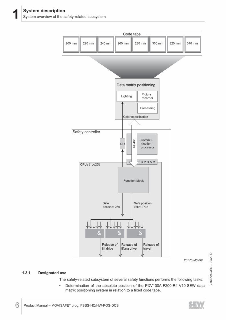
1.3 System overview of the safety-related subsystemThe safety-related subsystem consists of the following components:• MOVISAFE® HM31B/OGD/BSI safety controller• PXV100A‑F200‑R4‑V19‑SEW data matrix positioning system• SEW303-PXV function block for connecting the PXV100A‑F200‑R4‑V19_SEW
data matrix positioning system to the MOVISAFE® HM31B/OGD/BSI safety con-troller
• Connection cable (electrical interface) between the PXV100A data matrix position-ing system and the MOVISAFE® HM31B/OGD/BSI safety controller
2356
7252
/EN
– 0
9/20
17
1 System descriptionSystem overview of the safety-related subsystem
Product Manual – MOVISAFE® prog. FSSS-HC/HW-POS-DCS6
CPUs (1oo2D)
200 mm 220 mm 240 mm 260 mm 280 mm 300 mm 320 mm 340 mm
RS
48
5
DO
D P R A M
&&&
Code tape
Data matrix positioning
Picture
recorderLighting
Processing
Color specification
Safety controller
Commu-
nication
processor
Safe
position: 260
Safe position
valid: True
Function block
Release of
travel
Release of
lifting drive
Release of
tilt drive
20775340299
1.3.1 Designated useThe safety-related subsystem of several safety functions performs the following tasks:• Determination of the absolute position of the PXV100A‑F200‑R4‑V19‑SEW data
matrix positioning system in relation to a fixed code tape.
2356
7252
/EN
– 0
9/20
17
1System descriptionSystem overview of the safety-related subsystem
Product Manual – MOVISAFE® prog. FSSS-HC/HW-POS-DCS 7
• Calculation of the information as to whether the determined absolute position isvalid.
• Encapsulation of all monitoring and plausibility checks that are required in order toachieve the characteristic safety values of the safety-related subsystem.
1.3.2 Predictable misuse
DANGERIneffectiveness of the safety function.Severe or fatal injuries.• Use the safety-related subsystem only in an industrial environment.• Only operate the safety-related subsystem as described in this product manual
and in the user documentation of the components used.• The users of this safety-related subsystem must be trained specialists in accord-
ance with the user documentation of the hardware components that are used,and they must be familiar with the valid safety regulations, standards, directivesand laws for the respective application.
The safety-related subsystem is intended for use in an industrial environment andwithin closed buildings in accordance with this product manual. The safety-relatedsubsystem is not suitable for the following usage conditions, among other things:• Outdoors• Under water• Outside the designated use of the hardware components that are used• Use by unauthorized persons• Failure to heed the warnings pointed out by the signal words "DANGER" and
"CAUTION".
2356
7252
/EN
– 0
9/20
17
1 System descriptionScope of delivery
Product Manual – MOVISAFE® prog. FSSS-HC/HW-POS-DCS8
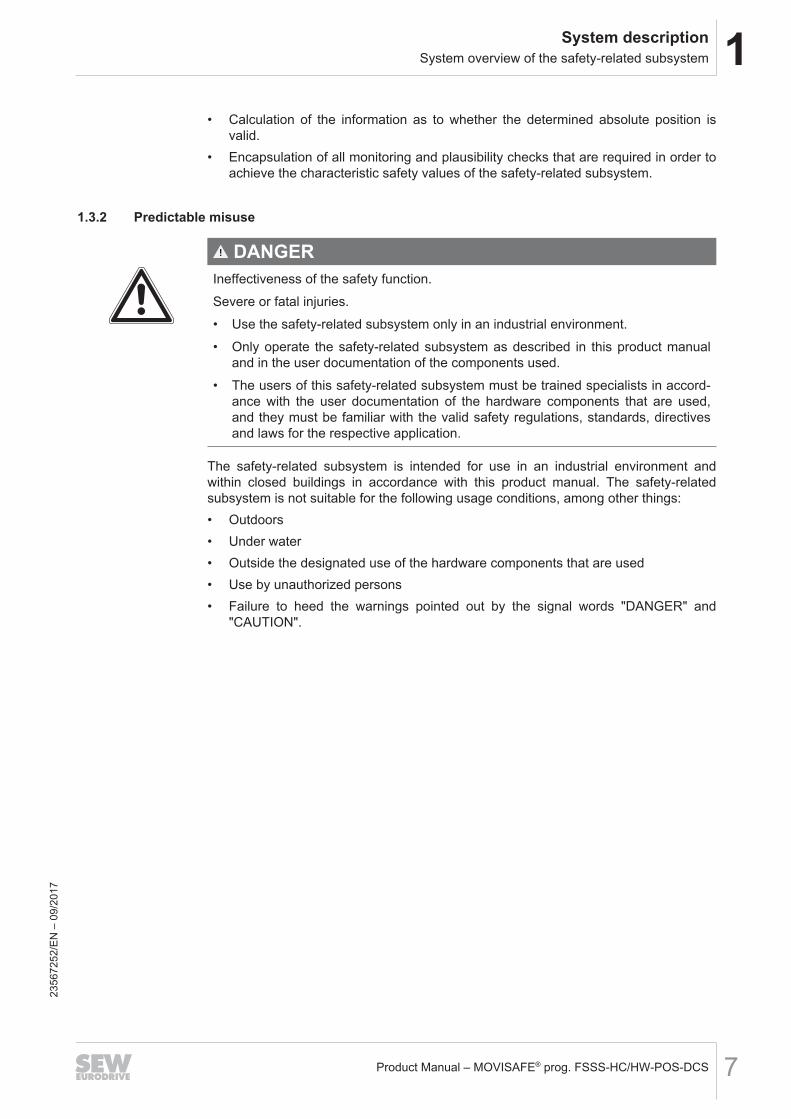
1.3.3 Electrical interface (connection cable)The PXV100A data matrix positioning system must have a connection cable (partnumber: 18191525) directly attached to the MOVISAFE® HM31/OGD/BSI safety con-troller. The PXV100A data matrix positioning system is supplied with additional energyvia this connection cable.No Y cables or the like to other components (such as non-safe controllers or otheridentical data matrix positioning systems) are permitted. The safety controller, the datamatrix positioning system and the connection cable form a closed subsystem.
24V_S
24V_L
24V_C
UR
UN
ER
RO
RPR
OG
FO
RC
EFA
ULT
USER
LED
1U
SER
LED
2BL
PFF - HM31
X4223
SERVICE
U1
R-CAN1off
on
R-CAN2off
on
F-D
O
(RS
48
5)
20775707403
1.4 Scope of delivery1.4.1 Without hardware components
The following components are included in the scope of delivery of the safety-relatedsubsystem MOVISAFE® prog. FSSS‑HW‑POS‑DCS without hardware components(part number: 18267483):• HM31 application software FSSS-HS-POS-DCS, part number: 18267491• Nameplate (self-adhesive) FSSS-HT-POS-DCS, part number: 28103343
1.4.2 With hardware componentsThe following components are included in the scope of delivery of the safety-relatedsubsystem MOVISAFE® prog. FSSS‑HC‑POS‑DCS with hardware components (partnumber: 18267475):• HM31 application software FSSS-HS-POS-DCS, part number: 18267491• Nameplate (self-adhesive) FSSS-HT-POS-DCS, part number: 28103343• MOVISAFE® HM31B safety controller (version PFF-HM31B/OGD/BSI), part num-
ber: 18265529• PXV100A‑F200‑R4‑V19‑SEW data matrix positioning system, part number:
19500394• Connection cable 0x02-F8AS-Sw-M5BA, variable length 0.5 – 30 m, part number:
18191525
2356
7252
/EN
– 0
9/20
17
1System descriptionDeclaration of conformity
Product Manual – MOVISAFE® prog. FSSS-HC/HW-POS-DCS 9
1.5 Declaration of conformity
INFORMATIONThis product has been developed and produced in accordance with applicableEuropean standards and directives (see chapter "Applied standards and directives").The declaration of conformity is available for download from the SEW website(www.sew‑eurodrive.com) under "Documentation".
2356
7252
/EN
– 0
9/20
17
2 Technical dataApplied standards and directives
Product Manual – MOVISAFE® prog. FSSS-HC/HW-POS-DCS10
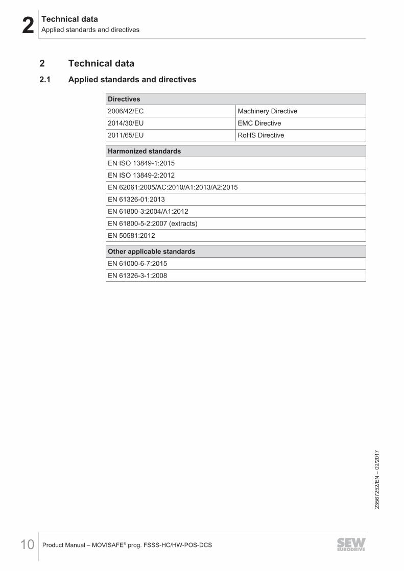
2 Technical data2.1 Applied standards and directives
Directives2006/42/EC Machinery Directive
2014/30/EU EMC Directive
2011/65/EU RoHS Directive
Harmonized standardsEN ISO 13849-1:2015
EN ISO 13849-2:2012
EN 62061:2005/AC:2010/A1:2013/A2:2015
EN 61326-01:2013
EN 61800-3:2004/A1:2012
EN 61800-5-2:2007 (extracts)
EN 50581:2012
Other applicable standardsEN 61000-6-7:2015
EN 61326-3-1:2008
2356
7252
/EN
– 0
9/20
17
2Technical dataCharacteristic safety values of the safety-related subsystem
Product Manual – MOVISAFE® prog. FSSS-HC/HW-POS-DCS 11
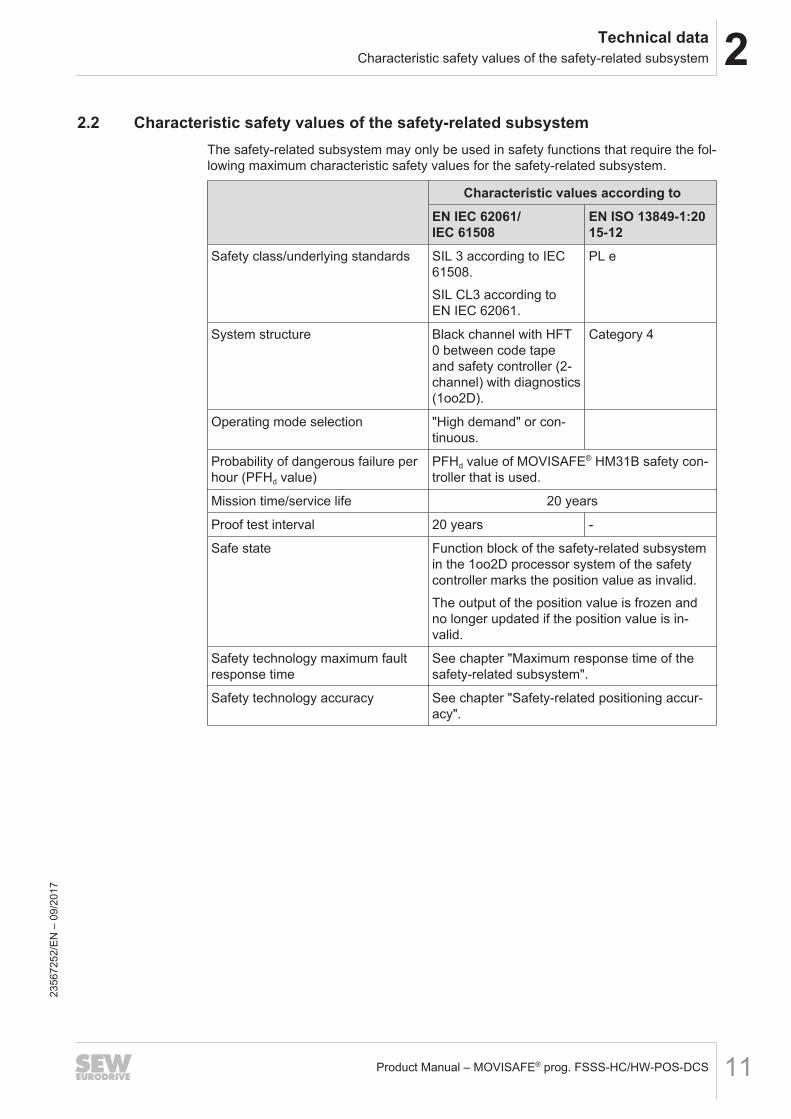
2.2 Characteristic safety values of the safety-related subsystemThe safety-related subsystem may only be used in safety functions that require the fol-lowing maximum characteristic safety values for the safety-related subsystem.
Characteristic values according toEN IEC 62061/IEC 61508
EN ISO 13849-1:2015-12
Safety class/underlying standards SIL 3 according to IEC61508.SIL CL3 according toEN IEC 62061.
PL e
System structure Black channel with HFT0 between code tapeand safety controller (2-channel) with diagnostics(1oo2D).
Category 4
Operating mode selection "High demand" or con-tinuous.
Probability of dangerous failure perhour (PFHd value)
PFHd value of MOVISAFE® HM31B safety con-troller that is used.
Mission time/service life 20 years
Proof test interval 20 years -
Safe state Function block of the safety-related subsystemin the 1oo2D processor system of the safetycontroller marks the position value as invalid.The output of the position value is frozen andno longer updated if the position value is in-valid.
Safety technology maximum faultresponse time
See chapter "Maximum response time of thesafety-related subsystem".
Safety technology accuracy See chapter "Safety-related positioning accur-acy".
2356
7252
/EN
– 0
9/20
17
3 SoftwareStructure of function block SEW303-PXV
Product Manual – MOVISAFE® prog. FSSS-HC/HW-POS-DCS12
3 Software3.1 Structure of function block SEW303-PXV
SEW303-PXV
O_stError
xTransBreak
udTimeStamp
dSafeWinMinus
dSafeWinPlus
xReset
uSenType
xFlashColor1
uConnState
dSafePosXuIncResTimeXColorCyc
uSenReadWinLenInMM
xIsExpPosXUseduHm31TargetCycTime
uCUTScheduleInterval
xSafePosX_OK
xNewData
uIncResTimeSlowColorCyc
stAddInfo
20703128971
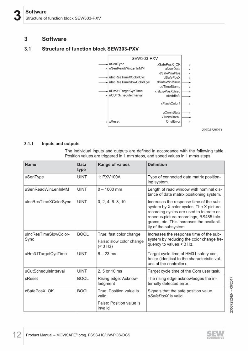
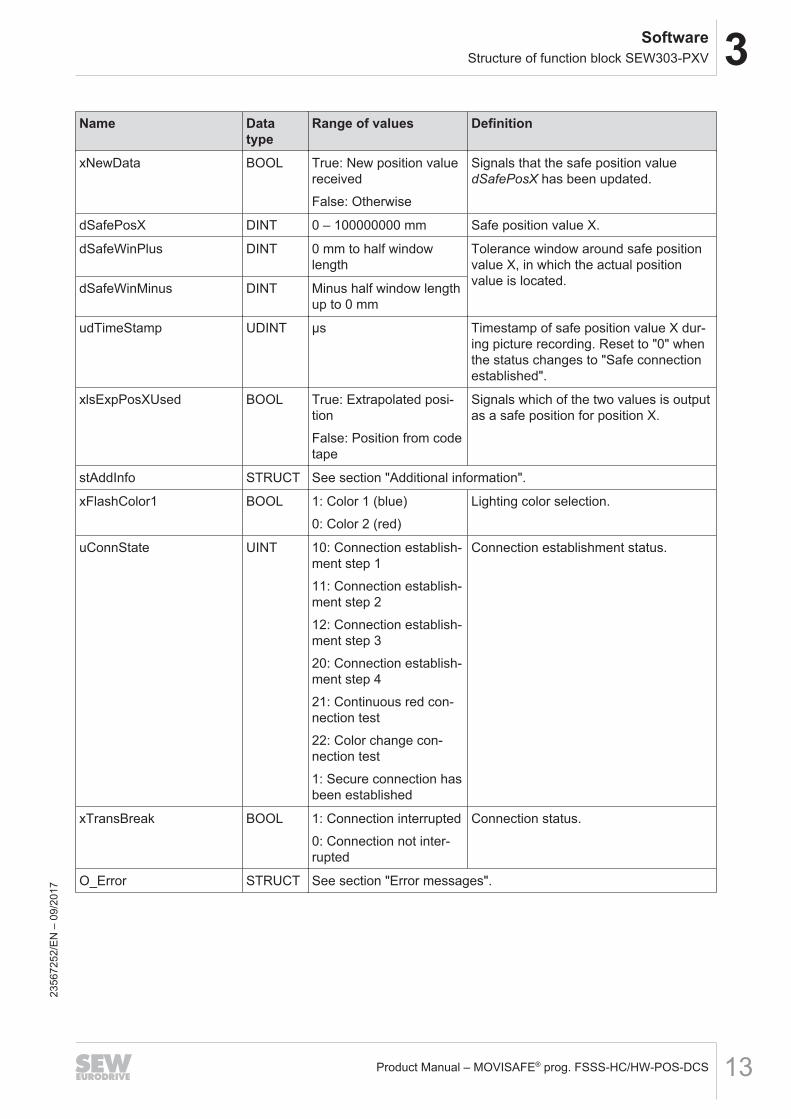
3.1.1 Inputs and outputsThe individual inputs and outputs are defined in accordance with the following table.Position values are triggered in 1 mm steps, and speed values in 1 mm/s steps.
Name Datatype
Range of values Definition
uSenType UINT 1: PXV100A Type of connected data matrix position-ing system.
uSenReadWinLenInMM UINT 0 – 1000 mm Length of read window with nominal dis-tance of data matrix positioning system.
ulncResTimeXColorSync UINT 0, 2, 4, 6. 8, 10 Increases the response time of the sub-system by X color cycles. The X picturerecording cycles are used to tolerate er-roneous picture recordings, RS485 tele-grams, etc. This increases the availabil-ity of the subsystem.
ulncResTimeSlowColor-Sync
BOOL True: fast color changeFalse: slow color change(< 3 Hz)
Increases the response time of the sub-system by reducing the color change fre-quency to values < 3 Hz.
uHm31TargetCycTime UINT 8 – 23 ms Target cycle time of HM31 safety con-troller (identical to the characteristic val-ues of the controller).
uCutScheduleInterval UINT 2, 5 or 10 ms Target cycle time of the Com user task.
xReset BOOL Rising edge: Acknow-ledgment
The rising edge acknowledges the in-ternally detected error.
xSafePosX_OK BOOL True: Position value isvalidFalse: Position value isinvalid
Signals that the safe position valuedSafePosX is valid.
2356
7252
/EN
– 0
9/20
17
3SoftwareStructure of function block SEW303-PXV
Product Manual – MOVISAFE® prog. FSSS-HC/HW-POS-DCS 13
Name Datatype
Range of values Definition
xNewData BOOL True: New position valuereceivedFalse: Otherwise
Signals that the safe position valuedSafePosX has been updated.
dSafePosX DINT 0 – 100000000 mm Safe position value X.
dSafeWinPlus DINT 0 mm to half windowlength
Tolerance window around safe positionvalue X, in which the actual positionvalue is located.dSafeWinMinus DINT Minus half window length
up to 0 mm
udTimeStamp UDINT µs Timestamp of safe position value X dur-ing picture recording. Reset to "0" whenthe status changes to "Safe connectionestablished".
xlsExpPosXUsed BOOL True: Extrapolated posi-tionFalse: Position from codetape
Signals which of the two values is outputas a safe position for position X.
stAddInfo STRUCT See section "Additional information".
xFlashColor1 BOOL 1: Color 1 (blue)0: Color 2 (red)
Lighting color selection.
uConnState UINT 10: Connection establish-ment step 111: Connection establish-ment step 212: Connection establish-ment step 320: Connection establish-ment step 421: Continuous red con-nection test22: Color change con-nection test1: Secure connection hasbeen established
Connection establishment status.
xTransBreak BOOL 1: Connection interrupted0: Connection not inter-rupted
Connection status.
O_Error STRUCT See section "Error messages".
2356
7252
/EN
– 0
9/20
17
3 SoftwareStructure of function block SEW303-PXV
Product Manual – MOVISAFE® prog. FSSS-HC/HW-POS-DCS14
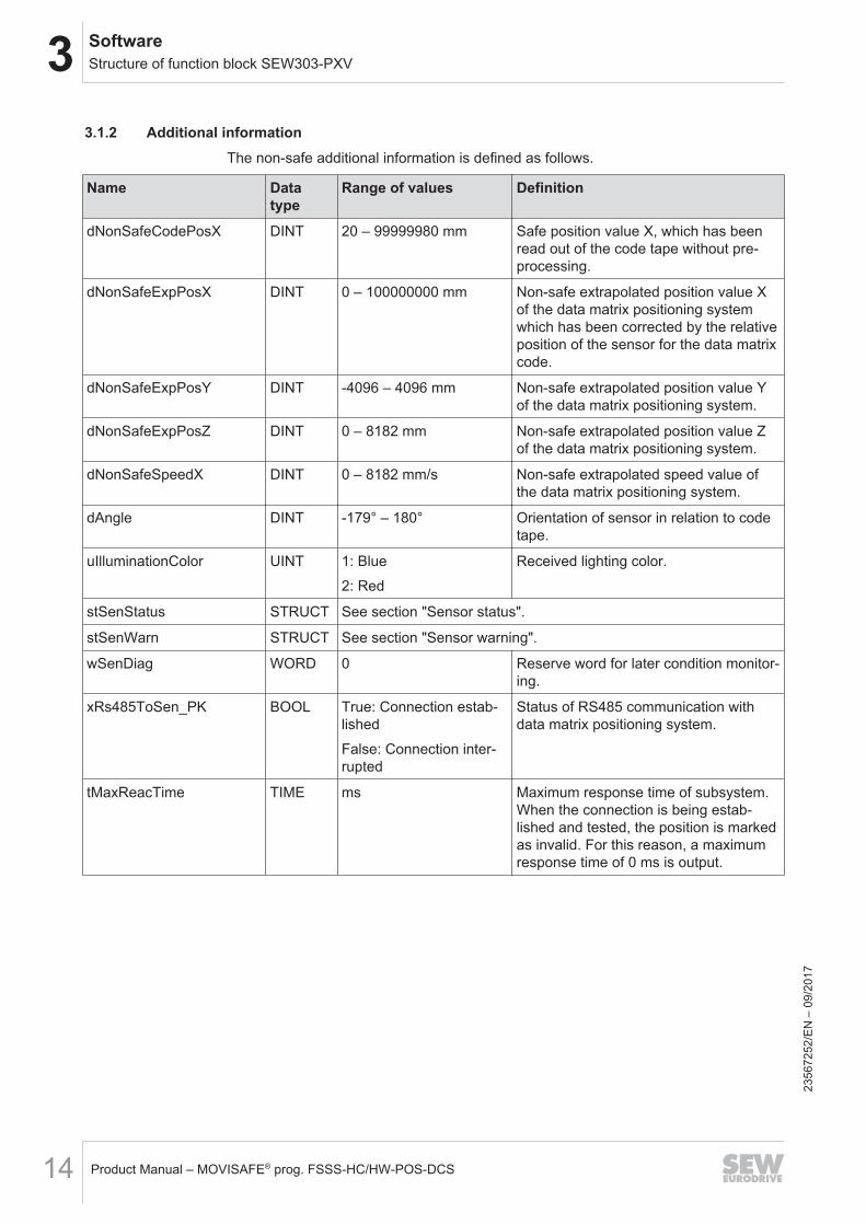
3.1.2 Additional informationThe non-safe additional information is defined as follows.
Name Datatype
Range of values Definition
dNonSafeCodePosX DINT 20 – 99999980 mm Safe position value X, which has beenread out of the code tape without pre-processing.
dNonSafeExpPosX DINT 0 – 100000000 mm Non-safe extrapolated position value Xof the data matrix positioning systemwhich has been corrected by the relativeposition of the sensor for the data matrixcode.
dNonSafeExpPosY DINT -4096 – 4096 mm Non-safe extrapolated position value Yof the data matrix positioning system.
dNonSafeExpPosZ DINT 0 – 8182 mm Non-safe extrapolated position value Zof the data matrix positioning system.
dNonSafeSpeedX DINT 0 – 8182 mm/s Non-safe extrapolated speed value ofthe data matrix positioning system.
dAngle DINT -179° – 180° Orientation of sensor in relation to codetape.
uIlluminationColor UINT 1: Blue2: Red
Received lighting color.
stSenStatus STRUCT See section "Sensor status".
stSenWarn STRUCT See section "Sensor warning".
wSenDiag WORD 0 Reserve word for later condition monitor-ing.
xRs485ToSen_PK BOOL True: Connection estab-lishedFalse: Connection inter-rupted
Status of RS485 communication withdata matrix positioning system.
tMaxReacTime TIME ms Maximum response time of subsystem.When the connection is being estab-lished and tested, the position is markedas invalid. For this reason, a maximumresponse time of 0 ms is output.
2356
7252
/EN
– 0
9/20
17
3SoftwareStructure of function block SEW303-PXV
Product Manual – MOVISAFE® prog. FSSS-HC/HW-POS-DCS 15
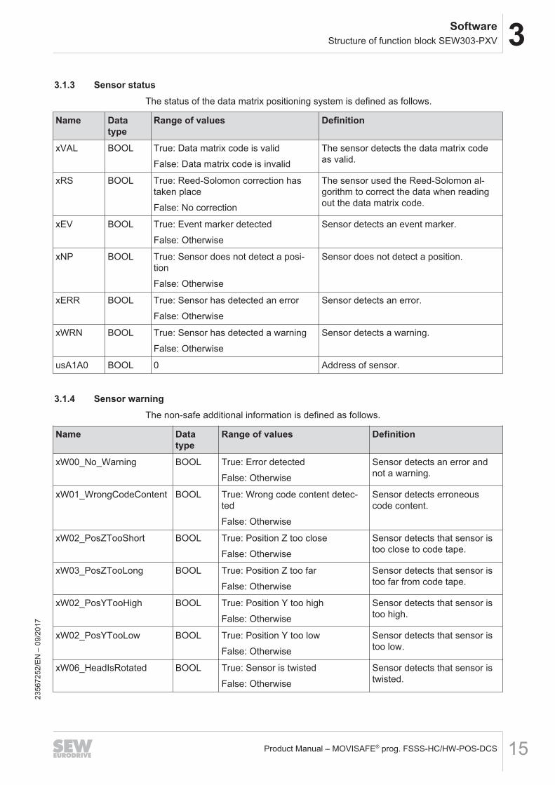
3.1.3 Sensor statusThe status of the data matrix positioning system is defined as follows.
Name Datatype
Range of values Definition
xVAL BOOL True: Data matrix code is validFalse: Data matrix code is invalid
The sensor detects the data matrix codeas valid.
xRS BOOL True: Reed-Solomon correction hastaken placeFalse: No correction
The sensor used the Reed-Solomon al-gorithm to correct the data when readingout the data matrix code.
xEV BOOL True: Event marker detectedFalse: Otherwise
Sensor detects an event marker.
xNP BOOL True: Sensor does not detect a posi-tionFalse: Otherwise
Sensor does not detect a position.
xERR BOOL True: Sensor has detected an errorFalse: Otherwise
Sensor detects an error.
xWRN BOOL True: Sensor has detected a warningFalse: Otherwise
Sensor detects a warning.
usA1A0 BOOL 0 Address of sensor.
3.1.4 Sensor warningThe non-safe additional information is defined as follows.
Name Datatype
Range of values Definition
xW00_No_Warning BOOL True: Error detectedFalse: Otherwise
Sensor detects an error andnot a warning.
xW01_WrongCodeContent BOOL True: Wrong code content detec-tedFalse: Otherwise
Sensor detects erroneouscode content.
xW02_PosZTooShort BOOL True: Position Z too closeFalse: Otherwise
Sensor detects that sensor istoo close to code tape.
xW03_PosZTooLong BOOL True: Position Z too farFalse: Otherwise
Sensor detects that sensor istoo far from code tape.
xW02_PosYTooHigh BOOL True: Position Y too highFalse: Otherwise
Sensor detects that sensor istoo high.
xW02_PosYTooLow BOOL True: Position Y too lowFalse: Otherwise
Sensor detects that sensor istoo low.
xW06_HeadIsRotated BOOL True: Sensor is twistedFalse: Otherwise
Sensor detects that sensor istwisted.
2356
7252
/EN
– 0
9/20
17
3 SoftwareStructure of function block SEW303-PXV
Product Manual – MOVISAFE® prog. FSSS-HC/HW-POS-DCS16
Name Datatype
Range of values Definition
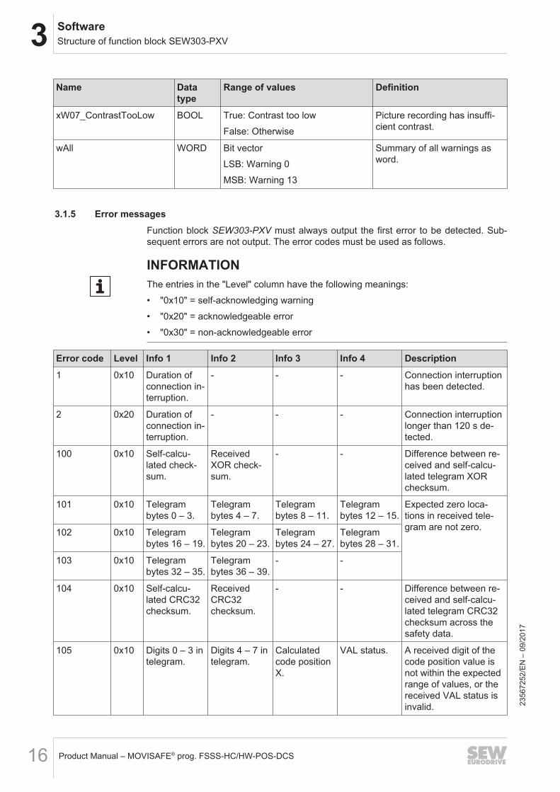
xW07_ContrastTooLow BOOL True: Contrast too lowFalse: Otherwise
Picture recording has insuffi-cient contrast.
wAll WORD Bit vectorLSB: Warning 0MSB: Warning 13
Summary of all warnings asword.
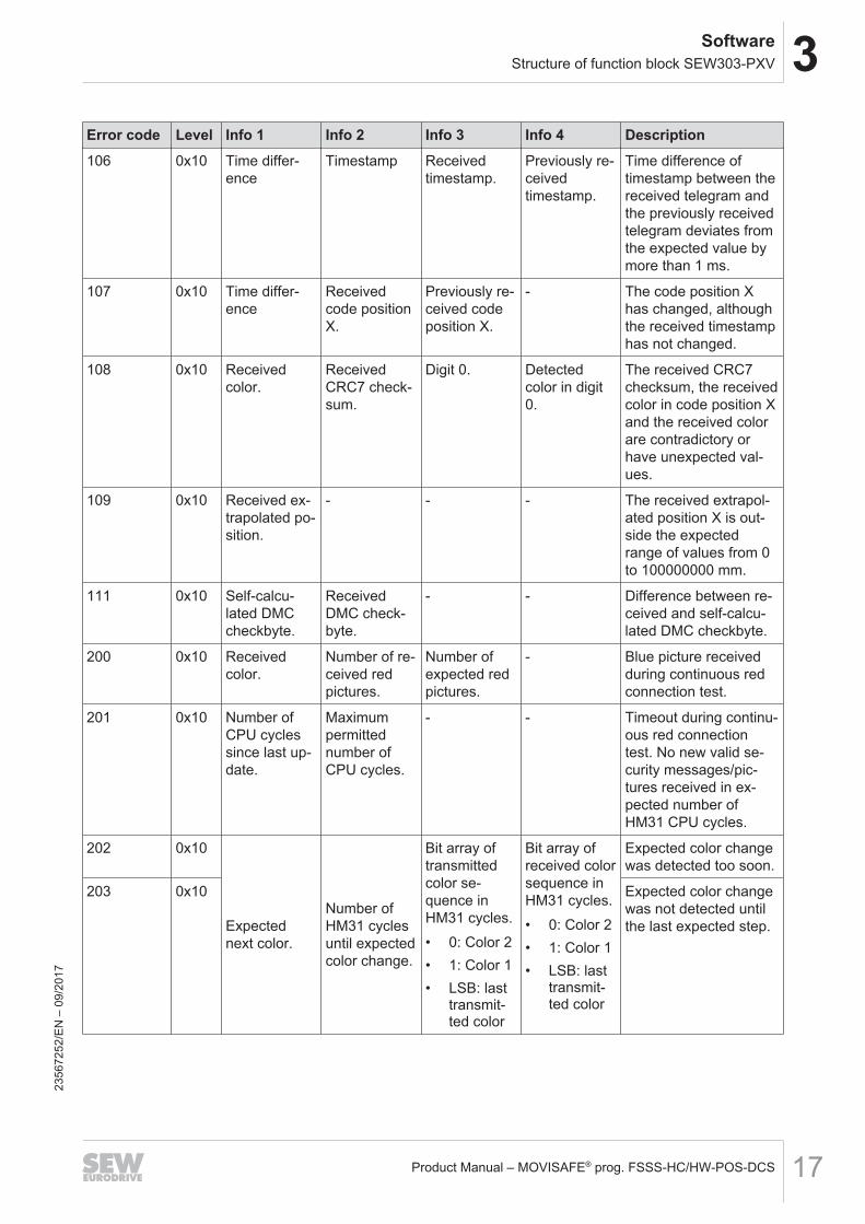
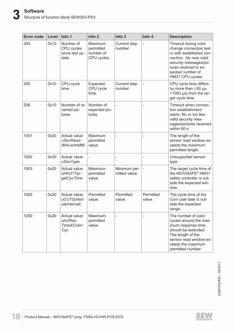
3.1.5 Error messagesFunction block SEW303-PXV must always output the first error to be detected. Sub-sequent errors are not output. The error codes must be used as follows.
INFORMATIONThe entries in the "Level" column have the following meanings:• "0x10" = self-acknowledging warning• "0x20" = acknowledgeable error• "0x30" = non-acknowledgeable error
Error code Level Info 1 Info 2 Info 3 Info 4 Description1 0x10 Duration of
connection in-terruption.
- - - Connection interruptionhas been detected.
2 0x20 Duration ofconnection in-terruption.
- - - Connection interruptionlonger than 120 s de-tected.
100 0x10 Self-calcu-lated check-sum.
ReceivedXOR check-sum.
- - Difference between re-ceived and self-calcu-lated telegram XORchecksum.
101 0x10 Telegrambytes 0 – 3.
Telegrambytes 4 – 7.
Telegrambytes 8 – 11.
Telegrambytes 12 – 15.
Expected zero loca-tions in received tele-gram are not zero.102 0x10 Telegram
bytes 16 – 19.Telegrambytes 20 – 23.
Telegrambytes 24 – 27.
Telegrambytes 28 – 31.
103 0x10 Telegrambytes 32 – 35.
Telegrambytes 36 – 39.
- -
104 0x10 Self-calcu-lated CRC32checksum.
ReceivedCRC32checksum.
- - Difference between re-ceived and self-calcu-lated telegram CRC32checksum across thesafety data.
105 0x10 Digits 0 – 3 intelegram.
Digits 4 – 7 intelegram.
Calculatedcode positionX.
VAL status. A received digit of thecode position value isnot within the expectedrange of values, or thereceived VAL status isinvalid. 23
5672
52/E
N –
09/
2017
3SoftwareStructure of function block SEW303-PXV
Product Manual – MOVISAFE® prog. FSSS-HC/HW-POS-DCS 17
Error code Level Info 1 Info 2 Info 3 Info 4 Description106 0x10 Time differ-
enceTimestamp Received
timestamp.Previously re-ceivedtimestamp.
Time difference oftimestamp between thereceived telegram andthe previously receivedtelegram deviates fromthe expected value bymore than 1 ms.
107 0x10 Time differ-ence
Receivedcode positionX.
Previously re-ceived codeposition X.
- The code position Xhas changed, althoughthe received timestamphas not changed.
108 0x10 Receivedcolor.
ReceivedCRC7 check-sum.
Digit 0. Detectedcolor in digit0.
The received CRC7checksum, the receivedcolor in code position Xand the received colorare contradictory orhave unexpected val-ues.
109 0x10 Received ex-trapolated po-sition.
- - - The received extrapol-ated position X is out-side the expectedrange of values from 0to 100000000 mm.
111 0x10 Self-calcu-lated DMCcheckbyte.
ReceivedDMC check-byte.
- - Difference between re-ceived and self-calcu-lated DMC checkbyte.
200 0x10 Receivedcolor.
Number of re-ceived redpictures.
Number ofexpected redpictures.
- Blue picture receivedduring continuous redconnection test.
201 0x10 Number ofCPU cyclessince last up-date.
Maximumpermittednumber ofCPU cycles.
- - Timeout during continu-ous red connectiontest. No new valid se-curity messages/pic-tures received in ex-pected number ofHM31 CPU cycles.
202 0x10
Expectednext color.
Number ofHM31 cyclesuntil expectedcolor change.
Bit array oftransmittedcolor se-quence inHM31 cycles.• 0: Color 2• 1: Color 1• LSB: last
transmit-ted color
Bit array ofreceived colorsequence inHM31 cycles.• 0: Color 2• 1: Color 1• LSB: last
transmit-ted color
Expected color changewas detected too soon.
203 0x10 Expected color changewas not detected untilthe last expected step.
2356
7252
/EN
– 0
9/20
17
3 SoftwareStructure of function block SEW303-PXV
Product Manual – MOVISAFE® prog. FSSS-HC/HW-POS-DCS18
Error code Level Info 1 Info 2 Info 3 Info 4 Description204 0x10 Number of
CPU cyclessince last up-date.
Maximumpermittednumber ofCPU cycles.
Current stepnumber.
- Timeout during colorchange connection testor with established con-nection. No new validsecurity messages/pic-tures received in ex-pected number ofHM31 CPU cycles.
205 0x10 CPU cycletime.
ExpectedCPU cycletime.
Current stepnumber.
- CPU cycle time differsby more than (-50 µs,+1050 µs) from the tar-get cycle time.
206 0x10 Number of re-ceived pic-tures.
Number ofexpected pic-tures.
- - Timeout when connec-tion establishmentstarts. No or too fewvalid security mes-sages/pictures receivedwithin 60 s.
1001 0x20 Actual valueuSenRead-WinLenlnMM.
Maximumpermittedvalue.
- - The length of thesensor read window ex-ceeds the maximumpermitted length.
1002 0x30 Actual valueuSenType.
- - - Unsupported sensortype.
1003 0x20 Actual valueuHm31Tar-getCycTime.
Maximumpermittedvalue.
Minimum per-mitted value.
- The target cycle time ofthe MOVISAFE® HM31safety controller is out-side the expected win-dow.
1005 0x30 Actual valueuCUTSched-uleIntervall.
Permittedvalue.
Permittedvalue.
Permittedvalue.
The cycle time of theCom user task is out-side the expectedrange.
1200 0x20 Actual valueulncRes-TimeXColor-Cyc.
Maximumpermittedvalue.
- - The number of colorcycles around the max-imum response timeshould be extended.The length of thesensor read window ex-ceeds the maximumpermitted number.
2356
7252
/EN
– 0
9/20
17
3SoftwareStructure of function block SEW303-PXV
Product Manual – MOVISAFE® prog. FSSS-HC/HW-POS-DCS 19
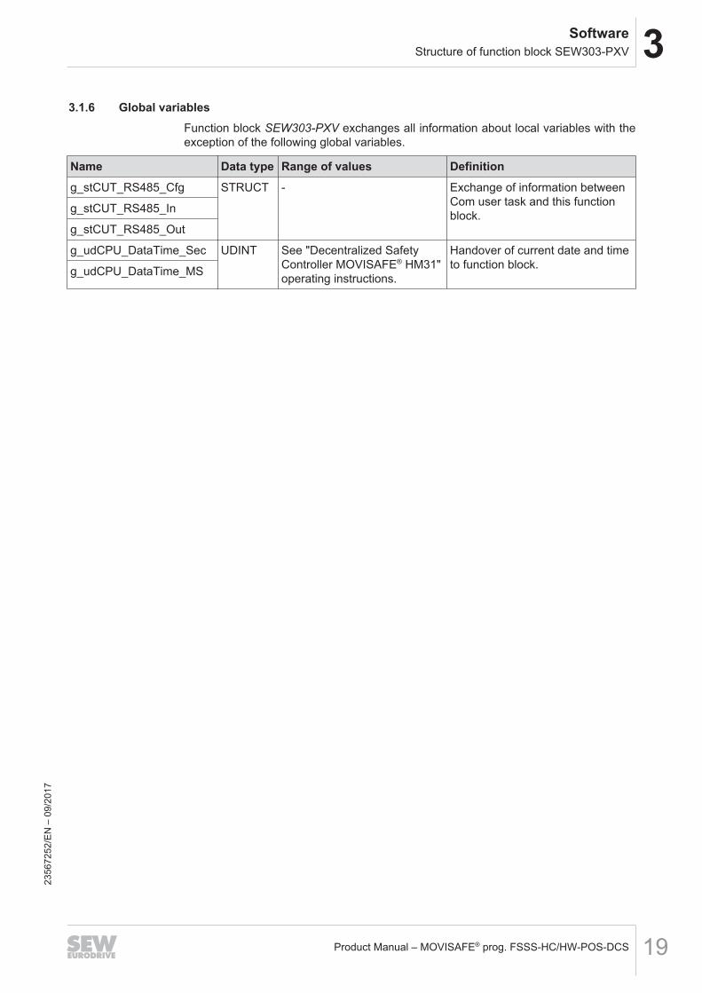
3.1.6 Global variablesFunction block SEW303‑PXV exchanges all information about local variables with theexception of the following global variables.
Name Data type Range of values Definitiong_stCUT_RS485_Cfg STRUCT - Exchange of information between
Com user task and this functionblock.g_stCUT_RS485_In
g_stCUT_RS485_Out
g_udCPU_DataTime_Sec UDINT See "Decentralized SafetyController MOVISAFE® HM31"operating instructions.
Handover of current date and timeto function block.g_udCPU_DataTime_MS
2356
7252
/EN
– 0
9/20
17
4 ConfigurationNameplate
Product Manual – MOVISAFE® prog. FSSS-HC/HW-POS-DCS20
4 Configuration
DANGERIneffectiveness of the safety function in the event of failure to observe the followingsub-chapters and the user documentation of the components used.Severe or fatal injuries.ü The following is essential:• Read this product manual and the user documentation of the components used
with care. Familiarize yourself with the device before installing, mounting, and op-erating it.
• Only operate the safety-related subsystem in the way that is described in thisproduct manual and in the user documentation of the components that are used.This will ensure that the device and the connected systems operate safely. Pro-tection of operating personnel and the system is only guaranteed if this safety-re-lated subsystem is operated according to its designated use.
• During startup, check whether the safety-related subsystem is being used in ac-cordance with the requirements of the following sub-chapters.
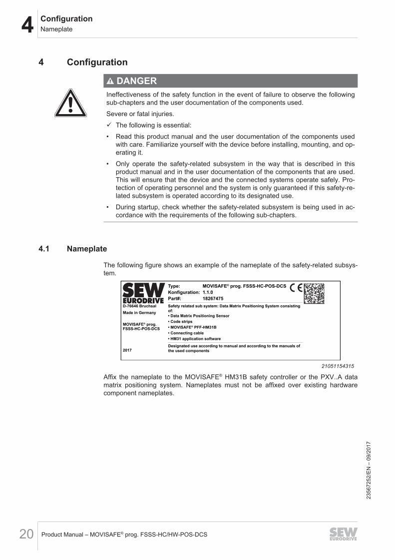
4.1 Nameplate
The following figure shows an example of the nameplate of the safety-related subsys-tem.
D-76646 Bruchsal
Made in Germany
MOVISAFE® prog.
MOVISAFE® prog. FSSS-HC-POS-DCS
1.1.0
18267475
Type:
Konfiguration:
Part#:
Safety related sub system: Data Matrix Positioning System consisting
of:
• Data Matrix Positioning Sensor
• Code strips
• MOVISAFE® PFF-HM31B
• HM31 application software
Designated use according to manual and according to the manuals of
the used components
• Connecting cableFSSS-HC-POS-DCS
2017
21051154315
Affix the nameplate to the MOVISAFE® HM31B safety controller or the PXV..A datamatrix positioning system. Nameplates must not be affixed over existing hardwarecomponent nameplates.
2356
7252
/EN
– 0
9/20
17
4ConfigurationReliability diagram
Product Manual – MOVISAFE® prog. FSSS-HC/HW-POS-DCS 21
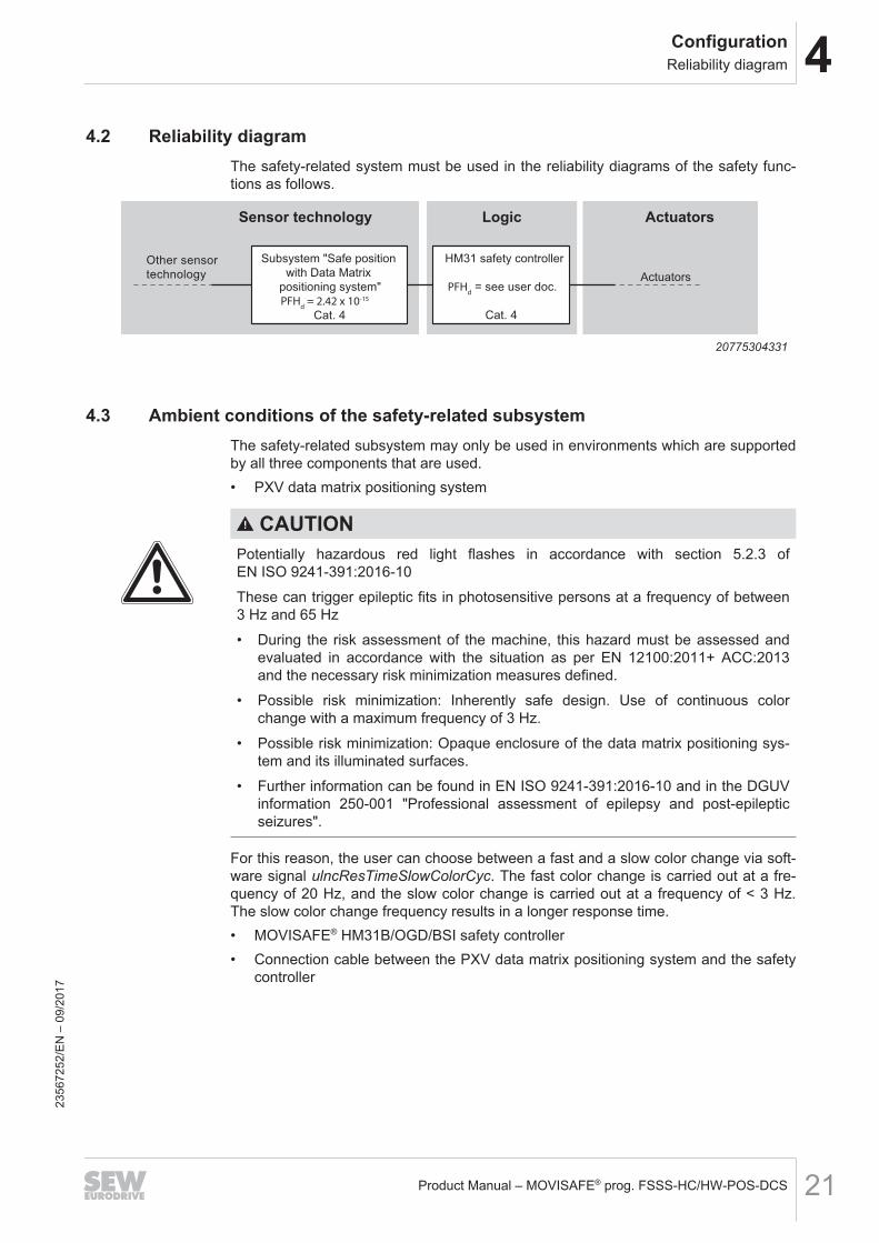
4.2 Reliability diagramThe safety-related system must be used in the reliability diagrams of the safety func-tions as follows.
PFHd = 2.42 x 10⁻¹⁵
PFHd
Sensor technology Logic Actuators
HM31 safety controller
Cat. 4
Subsystem "Safe position
with Data Matrix
positioning system"
Cat. 4
Other sensor
technology Actuators= see user doc.
20775304331
4.3 Ambient conditions of the safety-related subsystemThe safety-related subsystem may only be used in environments which are supportedby all three components that are used.• PXV data matrix positioning system
CAUTIONPotentially hazardous red light flashes in accordance with section 5.2.3 ofEN ISO 9241-391:2016-10These can trigger epileptic fits in photosensitive persons at a frequency of between3 Hz and 65 Hz• During the risk assessment of the machine, this hazard must be assessed and
evaluated in accordance with the situation as per EN 12100:2011+ ACC:2013and the necessary risk minimization measures defined.
• Possible risk minimization: Inherently safe design. Use of continuous colorchange with a maximum frequency of 3 Hz.
• Possible risk minimization: Opaque enclosure of the data matrix positioning sys-tem and its illuminated surfaces.
• Further information can be found in EN ISO 9241-391:2016-10 and in the DGUVinformation 250-001 "Professional assessment of epilepsy and post-epilepticseizures".
For this reason, the user can choose between a fast and a slow color change via soft-ware signal ulncResTimeSlowColorCyc. The fast color change is carried out at a fre-quency of 20 Hz, and the slow color change is carried out at a frequency of < 3 Hz.The slow color change frequency results in a longer response time.• MOVISAFE® HM31B/OGD/BSI safety controller• Connection cable between the PXV data matrix positioning system and the safety
controller
2356
7252
/EN
– 0
9/20
17
4 ConfigurationMaximum response time of the safety-related subsystem
Product Manual – MOVISAFE® prog. FSSS-HC/HW-POS-DCS22
4.3.1 Electromagnetic compatibilityThe safety-related subsystem, consisting of the above-mentioned 3 components, alsofulfills the following EMC standards:• EN 61000-6-7:2015• EN 61326-1:2013• EN 61326-3-1:2008• EN 61800-3:2004 + A1:2012 + AC:2014• IEC 61800-5-2:2016
4.4 Maximum response time of the safety-related subsystem
DANGERIneffectiveness of the safety function by extending the maximum response time.Severe or fatal injuries.• Please note that the response time increases with every increase at the ulncRes-
TimeXColorCyc input.• Please note that the maximum response time increases if the slow color change
is activated (input ulncResTimeSlowColorSync = True).• Particularly with subsequent modification of the two mentioned parameters, ana-
lyze the influence on your safety functions and take appropriate measures.
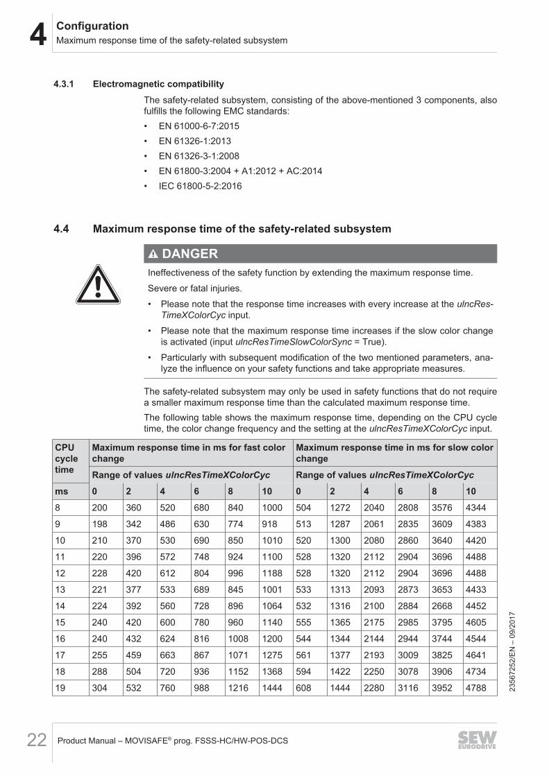
The safety-related subsystem may only be used in safety functions that do not requirea smaller maximum response time than the calculated maximum response time.The following table shows the maximum response time, depending on the CPU cycletime, the color change frequency and the setting at the ulncResTimeXColorCyc input.
CPUcycletime
Maximum response time in ms for fast colorchange
Maximum response time in ms for slow colorchange
Range of values ulncResTimeXColorCyc Range of values ulncResTimeXColorCycms 0 2 4 6 8 10 0 2 4 6 8 108 200 360 520 680 840 1000 504 1272 2040 2808 3576 4344
9 198 342 486 630 774 918 513 1287 2061 2835 3609 4383
10 210 370 530 690 850 1010 520 1300 2080 2860 3640 4420
11 220 396 572 748 924 1100 528 1320 2112 2904 3696 4488
12 228 420 612 804 996 1188 528 1320 2112 2904 3696 4488
13 221 377 533 689 845 1001 533 1313 2093 2873 3653 4433
14 224 392 560 728 896 1064 532 1316 2100 2884 2668 4452
15 240 420 600 780 960 1140 555 1365 2175 2985 3795 4605
16 240 432 624 816 1008 1200 544 1344 2144 2944 3744 4544
17 255 459 663 867 1071 1275 561 1377 2193 3009 3825 4641
18 288 504 720 936 1152 1368 594 1422 2250 3078 3906 4734
19 304 532 760 988 1216 1444 608 1444 2280 3116 3952 4788 2356
7252
/EN
– 0
9/20
17
4ConfigurationError response functions
Product Manual – MOVISAFE® prog. FSSS-HC/HW-POS-DCS 23
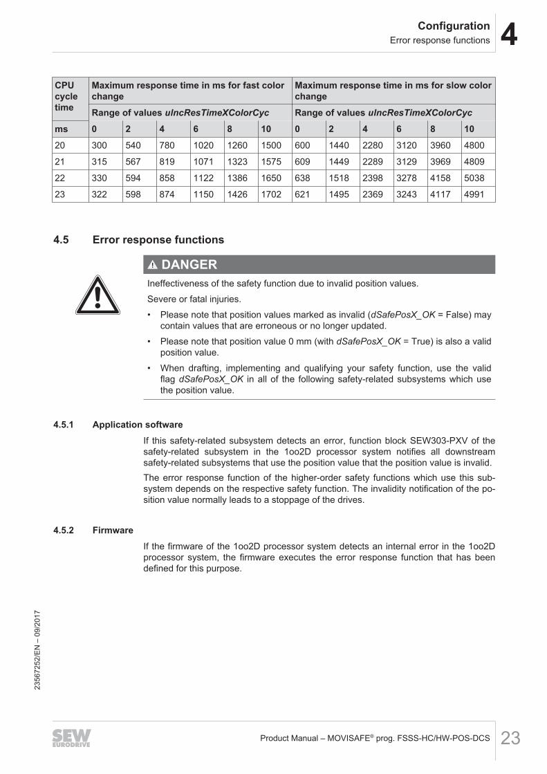
CPUcycletime
Maximum response time in ms for fast colorchange
Maximum response time in ms for slow colorchange
Range of values ulncResTimeXColorCyc Range of values ulncResTimeXColorCycms 0 2 4 6 8 10 0 2 4 6 8 1020 300 540 780 1020 1260 1500 600 1440 2280 3120 3960 4800
21 315 567 819 1071 1323 1575 609 1449 2289 3129 3969 4809
22 330 594 858 1122 1386 1650 638 1518 2398 3278 4158 5038
23 322 598 874 1150 1426 1702 621 1495 2369 3243 4117 4991
4.5 Error response functions
DANGERIneffectiveness of the safety function due to invalid position values.Severe or fatal injuries.• Please note that position values marked as invalid (dSafePosX_OK = False) may
contain values that are erroneous or no longer updated.• Please note that position value 0 mm (with dSafePosX_OK = True) is also a valid
position value.• When drafting, implementing and qualifying your safety function, use the valid
flag dSafePosX_OK in all of the following safety-related subsystems which usethe position value.
4.5.1 Application softwareIf this safety-related subsystem detects an error, function block SEW303‑PXV of thesafety-related subsystem in the 1oo2D processor system notifies all downstreamsafety-related subsystems that use the position value that the position value is invalid.The error response function of the higher-order safety functions which use this sub-system depends on the respective safety function. The invalidity notification of the po-sition value normally leads to a stoppage of the drives.
4.5.2 FirmwareIf the firmware of the 1oo2D processor system detects an internal error in the 1oo2Dprocessor system, the firmware executes the error response function that has beendefined for this purpose.
2356
7252
/EN
– 0
9/20
17
4 ConfigurationSafety-related positioning accuracy
Product Manual – MOVISAFE® prog. FSSS-HC/HW-POS-DCS24
4.6 Safety-related positioning accuracy
DANGERIneffectiveness of the safety function due to failure to observe the tolerance windowaround the safe position value.Severe or fatal injuries.• Please note that the safety-related positioning accuracy differs considerably from
the positioning accuracy described in the user documentation of the positioningsystem that is used.
• When drafting, implementing and qualifying your safety function, always use thesafety-related positioning accuracy
• Analyze the influence of the safety-related positioning accuracy and the tolerancewindow on your safety function. If necessary, use the dSafeWinMinus anddSafeWinPlus outputs in downstream subsystems.
• Check the correspondence of the uSenReadWinLenInMM parameter with theread window length of the data matrix positioning system that is used.
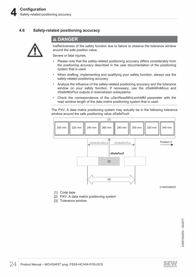
The PXV..A data matrix positioning system may actually be in the following tolerancewindow around the safe positioning value dSafePosX.
200 mm 220 mm 240 mm 260 mm 280 mm
dSafePosX
dSafeWinPlusdSafeWinMinus
300 mm 320 mm 340 mm
Position X
[1]
[2]
[3]
21940346635
[1] Code tape[2] PXV..A data matrix positioning system[3] Tolerance window
2356
7252
/EN
– 0
9/20
17
4ConfigurationLimits of the PXV..A data matrix positioning system
Product Manual – MOVISAFE® prog. FSSS-HC/HW-POS-DCS 25
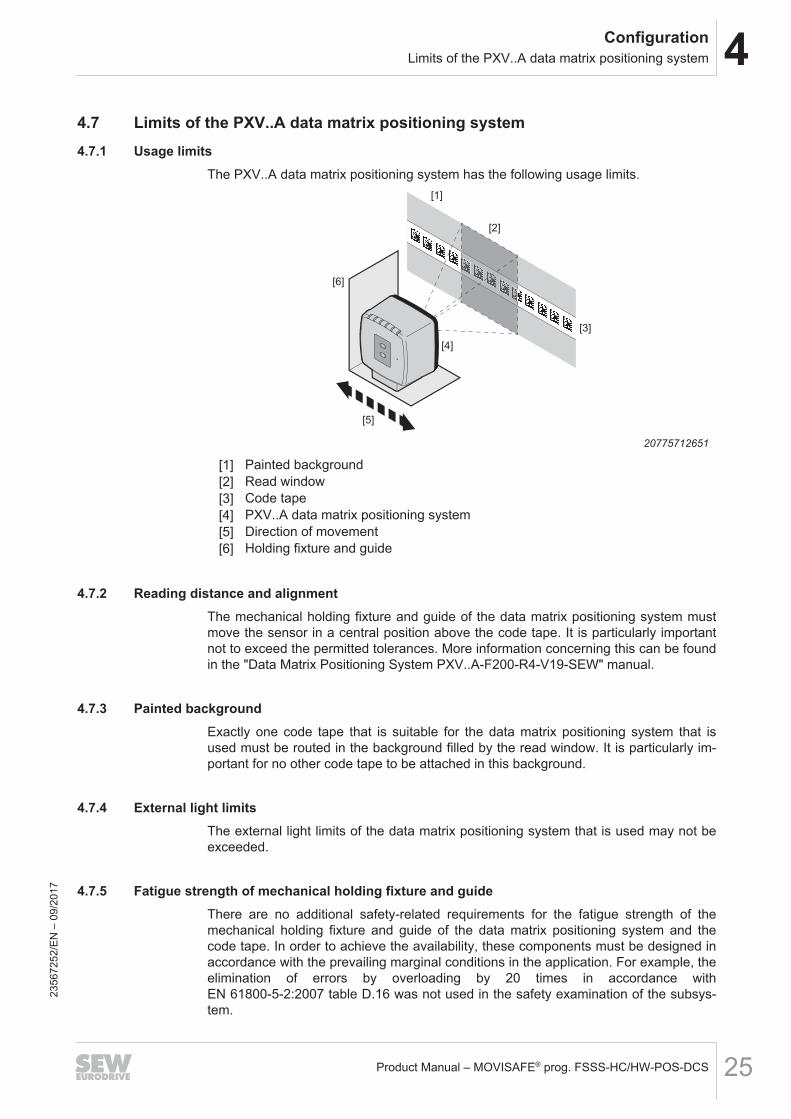
4.7 Limits of the PXV..A data matrix positioning system4.7.1 Usage limits
The PXV..A data matrix positioning system has the following usage limits.[1]
[2]
[3]
[4]
[5]
[6]
20775712651
[1] Painted background[2] Read window[3] Code tape[4] PXV..A data matrix positioning system[5] Direction of movement[6] Holding fixture and guide
4.7.2 Reading distance and alignmentThe mechanical holding fixture and guide of the data matrix positioning system mustmove the sensor in a central position above the code tape. It is particularly importantnot to exceed the permitted tolerances. More information concerning this can be foundin the "Data Matrix Positioning System PXV..A-F200-R4-V19-SEW" manual.
4.7.3 Painted backgroundExactly one code tape that is suitable for the data matrix positioning system that isused must be routed in the background filled by the read window. It is particularly im-portant for no other code tape to be attached in this background.
4.7.4 External light limitsThe external light limits of the data matrix positioning system that is used may not beexceeded.
4.7.5 Fatigue strength of mechanical holding fixture and guideThere are no additional safety-related requirements for the fatigue strength of themechanical holding fixture and guide of the data matrix positioning system and thecode tape. In order to achieve the availability, these components must be designed inaccordance with the prevailing marginal conditions in the application. For example, theelimination of errors by overloading by 20 times in accordance withEN 61800-5-2:2007 table D.16 was not used in the safety examination of the subsys-tem.
2356
7252
/EN
– 0
9/20
17
4 ConfigurationLimits of the PXV..A data matrix positioning system
Product Manual – MOVISAFE® prog. FSSS-HC/HW-POS-DCS26
4.7.6 Connection leadOnly the tested and approved connection leads with shield are permitted as the con-nection lead (electrical interface).Further information can be found in the "Data Matrix Positioning System PXV..A-F200-R4-V19-SEW" manual.
4.7.7 No second identical lighting unitNo other lighting unit with comparable red/blue flashing behavior may cast light intothe read window.
4.7.8 No code tape gapsThe entire travel section may not contain code tape gaps which are bigger than thecode tape gaps that are needed for the position sensor that is used. More informationconcerning this can be found in the "Data Matrix Positioning System PXV..A-F200-R4-V19-SEW" manual.
4.7.9 Component assemblyThe installation of the respective components must take place in accordance with therespective user documentation for the components.
4.7.10 Testing during startup
DANGERIneffectiveness of the safety function due to faulty installation of the positioning sys-tem or by affixing code tapes with the wrong position ranges.Severe or fatal injuries.• Please note that the requirements in accordance with chapter "Limits of the data
matrix positioning system PXV..A" must be adhered to.• Only use the hardware that has been specially validated for this safety-related
subsystem, and check the CRC checksums of the function blocks after everyuser software code generation (see chapter "Configuration management").
• Perform this check during initial startup and after every modification or repair(e.g. after attaching repair tapes).
• During the startup of the safety-related subsystem, the entire travel section mustbe traveled and the respective expected position compared with the reliable posi-tion readout.
• After attaching a repair tape over a defective or damaged area of an existing codetape, this area must be re-checked.
2356
7252
/EN
– 0
9/20
17
4ConfigurationLimits of the PXV..A data matrix positioning system
Product Manual – MOVISAFE® prog. FSSS-HC/HW-POS-DCS 27
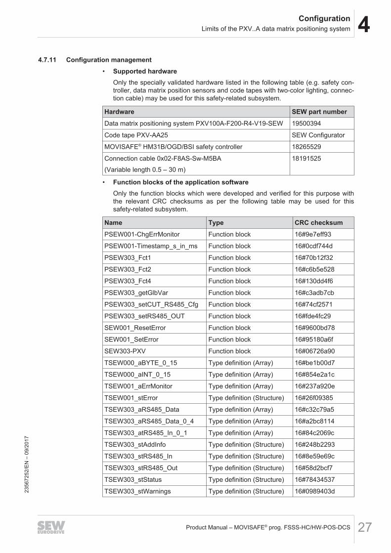
4.7.11 Configuration management• Supported hardware
Only the specially validated hardware listed in the following table (e.g. safety con-troller, data matrix position sensors and code tapes with two-color lighting, connec-tion cable) may be used for this safety-related subsystem.
Hardware SEW part numberData matrix positioning system PXV100A-F200-R4-V19-SEW 19500394
Code tape PXV-AA25 SEW Configurator
MOVISAFE® HM31B/OGD/BSI safety controller 18265529
Connection cable 0x02-F8AS-Sw-M5BA(Variable length 0.5 – 30 m)
18191525
• Function blocks of the application softwareOnly the function blocks which were developed and verified for this purpose withthe relevant CRC checksums as per the following table may be used for thissafety-related subsystem.
Name Type CRC checksumPSEW001-ChgErrMonitor Function block 16#9e7eff93
PSEW001-Timestamp_s_in_ms Function block 16#0cdf744d
PSEW303_Fct1 Function block 16#70b12f32
PSEW303_Fct2 Function block 16#c6b5e528
PSEW303_Fct4 Function block 16#130dd4f6
PSEW303_getGlbVar Function block 16#c3adb7cb
PSEW303_setCUT_RS485_Cfg Function block 16#74cf2571
PSEW303_setRS485_OUT Function block 16#fde4fc29
SEW001_ResetError Function block 16#9600bd78
SEW001_SetError Function block 16#95180a6f
SEW303-PXV Function block 16#06726a90
TSEW000_aBYTE_0_15 Type definition (Array) 16#be1b00d7
TSEW000_aINT_0_15 Type definition (Array) 16#854e2a1c
TSEW001_aErrMonitor Type definition (Array) 16#237a920e
TSEW001_stError Type definition (Structure) 16#26f09385
TSEW303_aRS485_Data Type definition (Array) 16#c32c79a5
TSEW303_aRS485_Data_0_4 Type definition (Array) 16#a2bc8114
TSEW303_atRS485_In_0_1 Type definition (Array) 16#84c2069c
TSEW303_stAddInfo Type definition (Structure) 16#248b2293
TSEW303_stRS485_In Type definition (Structure) 16#8e59e69c
TSEW303_stRS485_Out Type definition (Structure) 16#58d2bcf7
TSEW303_stStatus Type definition (Structure) 16#78434537
TSEW303_stWarnings Type definition (Structure) 16#0989403d2356
7252
/EN
– 0
9/20
17
4 ConfigurationSEW303-PXV function block
Product Manual – MOVISAFE® prog. FSSS-HC/HW-POS-DCS28
Name Type CRC checksumTSEW901_stErrorCUT Type definition (Structure) 16#2e6e4daf
TSEW902_aRS485_Buffer Type definition (Array) 16#f8afcff7
TSEW902_aRS485_Data Type definition (Array) 16#62b2bf81
TSEW902_stRS485_Buffer Type definition (Structure) 16#41ffbd71
TSEW902_stRS485_Cfg Type definition (Structure) 16#348e92f2
TSEW902_stRS485_In Type definition (Structure) 16#2f6fcda2
TSEW902_stRS485_Out Type definition (Structure) 16#e9141062
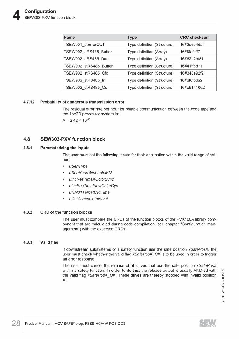
4.7.12 Probability of dangerous transmission errorThe residual error rate per hour for reliable communication between the code tape andthe 1oo2D processor system is:Λ = 2.42 × 10⁻¹⁵
4.8 SEW303-PXV function block4.8.1 Parameterizing the inputs
The user must set the following inputs for their application within the valid range of val-ues:• uSenType• uSenReadWinLenInMM• ulncResTimeXColorSync• ulncResTimeSlowColorCyc• uHM31TargetCycTime• uCutScheduleInterval
4.8.2 CRC of the function blocksThe user must compare the CRCs of the function blocks of the PVX100A library com-ponent that are calculated during code compilation (see chapter "Configuration man-agement") with the expected CRCs.
4.8.3 Valid flagIf downstream subsystems of a safety function use the safe position xSafePosX, theuser must check whether the valid flag xSafePosX_OK is to be used in order to triggeran error response.The user must cancel the release of all drives that use the safe position xSafePosXwithin a safety function. In order to do this, the release output is usually AND-ed withthe valid flag xSafePosX_OK. These drives are thereby stopped with invalid positionX.
2356
7252
/EN
– 0
9/20
17
4ConfigurationSEW303-PXV function block
Product Manual – MOVISAFE® prog. FSSS-HC/HW-POS-DCS 29
4.8.4 Tolerance windowIn all downstream subsystems of a safety function that use the safe position xSafe-PosX, the user must check whether the tolerance window of outputs dSafeWinMinusto dSafeWinPlus has an influence on the execution of the safety function.
4.8.5 Additional information
DANGERIneffectiveness of the safety function due to use of non-safety-related additional in-formation.Severe or fatal injuries.• Please note that many values in the additional information are read directly from
the data matrix positioning system without further verification within the safetycontroller.
• The additional information must only be used in a non-safety-related way, e.g. fordiagnostic purposes.
The user may use the additional information in a non-safety-related way at outputstAddInfo (e.g. as part of a safety function).
2356
7252
/EN
– 0
9/20
17
4 ConfigurationSEW303-PXV function block
Product Manual – MOVISAFE® prog. FSSS-HC/HW-POS-DCS30
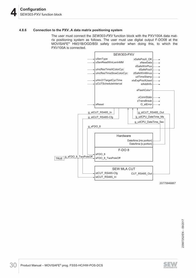
4.8.6 Connection to the PXV..A data matrix positioning systemThe user must connect the SEW303-PXV function block with the PXV100A data mat-rix positioning system as follows. The user must use digital output F-DO08 at theMOVISAFE® HM31B/OGD/BSI safety controller when doing this, to which thePXV100A is connected.
SEW303-PXV
O_stError
xTransBreak
udTimeStamp
dSafeWinMinus
dSafeWinPlus
xReset
uSenType
xFlashColor1
uConnState
dSafePosXuIncResTimeXColorCyc
uSenReadWinLenInMM
xIsExpPosXUseduHm31TargetCycTime
uCUTScheduleInterval
xSafePosX_OK
xNewData
uIncResTimeSlowColorCyc
stAddInfo
Hardware
Date/time [ms portion]
g_udCPU_DateTime_Sec
g_udCPU_DateTime_Ms
Date/time [s portion]
F-DO 8
xFDO_8
g_xFDO_8
xFDO_8_TwoPoleOffg_xFDO_8_TwoPoleOff
TRUE
SEW MLA CUT
stCUT_RS485-Cfg
g_stCUT_RS485-Cfg
CUT_RS485_Out
stCUT_RS485_In
g_stCUT_RS485_In g_stCUT_RS485_Out
2077584986723
5672
52/E
N –
09/
2017
5ServiceRegular inspections, maintenance, service, repair
Product Manual – MOVISAFE® prog. FSSS-HC/HW-POS-DCS 31
5 Service5.1 Regular inspections, maintenance, service, repair
Regular inspections, service, maintenance and repairs to the components must beperformed according to the respective user documentation (see chapter "Other applic-able documentation"). No additional inspections, maintenance, service or repairs arerequired for the subsystem.Defective components are replaced at the usage location in accordance with the re-spective user documentation (see chapter "Other applicable documentation").
2356
7252
/EN
– 0
9/20
17
Index
IndexA
Applied standards and directives ........................ 10
C
Characteristic safety values ................................ 11Configuration
Electromagnetic compatibility......................... 22Limits of the PXV..A data matrix positioning sys-tem ................................................................. 25Reliability diagram.......................................... 21SEW303-PXV function block.......................... 28
Configuration managementFunction blocks of the application software.... 27Supported hardware....................................... 27
D
Declaration of conformity....................................... 9
E
Error response functionsApplication software ....................................... 23Firmware ........................................................ 23
G
General informationOther applicable documentation....................... 5
N
Nameplate ........................................................... 20
O
Other applicable documentation............................ 5
P
PXV..A data matrix positioning systemConnection cables.......................................... 26External light limits ......................................... 25Fatigue strength of mechanical holding fixtureand guide........................................................ 25No code tape gaps ......................................... 26No second lighting unit ................................... 26Painted background ....................................... 25Reading distance and alignment .................... 25Usage limits.................................................... 25
R
Reliability diagram ............................................... 21
S
Safety-related positioning accuracy .................... 24Safety-related subsystem
Ambient conditions ......................................... 21Characteristic safety values ........................... 11Component assembly..................................... 26Configuration management ............................ 27Designated use ................................................ 6Electrical interface (connection cable).............. 8Error response functions ................................ 23Limits of the PXV..A data matrix positioning sys-tem ................................................................. 25Maximum response time ................................ 22Nameplate ...................................................... 20Probability of dangerous transmission error... 28Regular inspections, maintenance, service, re-pair ................................................................. 31Safety-related positioning accuracy ............... 24System overview of components...................... 5Testing during startup..................................... 26
Scope of deliveryWith hardware components.............................. 8Without hardware components......................... 8
SEW303-PXV function blockAdditional information............................... 14, 29Compare CRCs .............................................. 28Connection to the PXV..A data matrix position-ing system ...................................................... 30Error messages .............................................. 16Evaluating the tolerance window.................... 29Evaluating the valid flag ................................. 28Global variables.............................................. 19Inputs and outputs.......................................... 12Parameterizing the inputs............................... 28Sensor status ................................................. 15Sensor warning .............................................. 15
SoftwareStructure of SEW303-PXV function block ...... 12
System descriptionGeneral description .......................................... 5
2356
7252
/EN
– 0
9/17
Product Manual – MOVISAFE® prog. FSSS-HC/HW-POS-DCS32
Index
System overview of the safety-related subsys-tem ................................................................... 5
T
Technical dataApplied standards and directives ................... 10
2356
7252
/EN
– 0
9/17
Product Manual – MOVISAFE® prog. FSSS-HC/HW-POS-DCS 33

SEW-EURODRIVE—Driving the world
SEW-EURODRIVE GmbH & Co KGErnst-Blickle-Str. 4276646 BRUCHSALGERMANYTel. +49 7251 75-0Fax +49 7251 [email protected]
Related Documents