24 December 2013 PMI Revision 00 1 FSSS LOGIC SYSTEM

Welcome message from author
This document is posted to help you gain knowledge. Please leave a comment to let me know what you think about it! Share it to your friends and learn new things together.
Transcript

8/13/2019 FSSS LOGIC SYSTEM.ppt
http://slidepdf.com/reader/full/fsss-logic-systemppt 1/51

8/13/2019 FSSS LOGIC SYSTEM.ppt
http://slidepdf.com/reader/full/fsss-logic-systemppt 2/51
24 December 2013 PMI Revision 00 2
Furnace Safeguard Supervisory
System• Satisfactory Boiler start up
• Start up of individual oil system AB/CD/EF
• Operation of fuel firing subject to certain conditions
A/B/C/D/F
• Protection and interlock of oil /Coal System
8/13/2019 FSSS LOGIC SYSTEM.ppt
http://slidepdf.com/reader/full/fsss-logic-systemppt 3/51
24 December 2013 PMI Revision 00 3
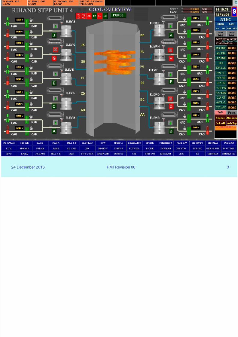
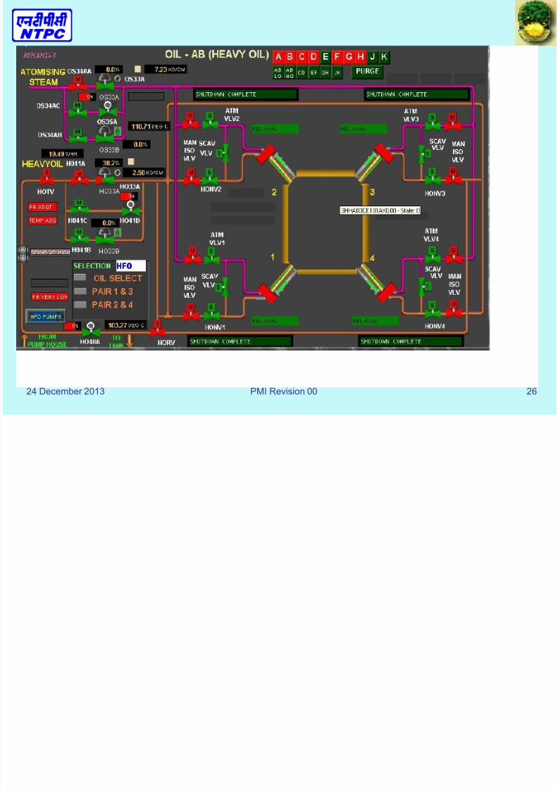
Typical Graphic Display of fuelfiring
•244 subscriptions (requests)
for data from the DPU.
•75 maxSCRIPTS
•30 Buttons
•
29 List Controls
•3 Bar Charts
•14 Text State controls
•
45 objects have dynamicborders
•200K of various static bitmaps
8/13/2019 FSSS LOGIC SYSTEM.ppt
http://slidepdf.com/reader/full/fsss-logic-systemppt 4/51
24 December 2013 PMI Revision 00 4
BOILER START- UP
SEQUENCE
• The boiler can be placed in service, initially orafter a “Master Fuel Trip,” in the following
sequence through FSSS.
Furnace Purge
• Before any fuel firing can takes place, initially or
following a boiler trip, a satisfactory “Purge Cycle” must be completed.

8/13/2019 FSSS LOGIC SYSTEM.ppt
http://slidepdf.com/reader/full/fsss-logic-systemppt 5/51
24 December 2013 PMI Revision 00 5
• Initially, the Heavy Oil must be recirculated and
heated to obtain the proper temperature and
viscosity for efficient combustion. After this is
accomplished, the Heavy Oil Trip Valve (HOTV)
can be closed and then the „furnace purge
cycle‟ can be started.
8/13/2019 FSSS LOGIC SYSTEM.ppt
http://slidepdf.com/reader/full/fsss-logic-systemppt 6/51
24 December 2013 PMI Revision 00 6
• After the furnace purge cycle is completed, the heavy oil
elevation (AB, CD, EF, & GH) can be taken into service. Anoil elevation is said to be “In Service,” when at least three
out of four heavy oil nozzle valves are open and the flame
is sensed by the scanners.
• After the heavy oil elevation is „in service‟, either of the
adjacent coal elevation can be taken into service because
“Ignition Permit” is now available for starting the pulverizer.
8/13/2019 FSSS LOGIC SYSTEM.ppt
http://slidepdf.com/reader/full/fsss-logic-systemppt 7/51
24 December 2013 PMI Revision 00 7
• A Coal elevation is said to be “In Service” after
the Pulverizer is ON, its Hot Air Gate (HAG) is
open and the associated Feeder is proven (i.e.,
feeder ON for more than 50 seconds). A “fireball” signal is established when the associated fireball
flame scanner senses flame and “ELEVATION
FLAME” indicator is illuminated on the FSSSconsole in control room.
8/13/2019 FSSS LOGIC SYSTEM.ppt
http://slidepdf.com/reader/full/fsss-logic-systemppt 8/51
24 December 2013 PMI Revision 00 8
Unit start up sequence
• Boiler purge operation
• Start up of oil firing(AB,CD,FH & GH)
• Adequate Ignition permit
• Firing of coal elevation(A,B,C,D,E,F,G & H)
• Flame sensing by scanners.

8/13/2019 FSSS LOGIC SYSTEM.ppt
http://slidepdf.com/reader/full/fsss-logic-systemppt 9/51
24 December 2013 PMI Revision 00 9
FSSS LOGIC
FSSS logics can be broadly divided
into 3 sections.
• Unit Logic.
• Oil Elevation Logic.
• Coal Elevation Logic

8/13/2019 FSSS LOGIC SYSTEM.ppt
http://slidepdf.com/reader/full/fsss-logic-systemppt 10/51

8/13/2019 FSSS LOGIC SYSTEM.ppt
http://slidepdf.com/reader/full/fsss-logic-systemppt 11/51
24 December 2013 PMI Revision 00 11
FURNACE PURGE
Purpose: :
Complete Removal of unburnt fuel from entire furnace
Procedure: Ensure that all fuel to furnace is cut off and all flame is out
Provide adequate air flow through furnace (30 to 40%)
Initiate a MANDATORY purge time cycle (9 min)
Consequence: Master Fuel Trip Relays are reset
Firing of fuel into the furnace is allowed

8/13/2019 FSSS LOGIC SYSTEM.ppt
http://slidepdf.com/reader/full/fsss-logic-systemppt 12/51
24 December 2013 PMI Revision 00 12
A. Unit Logic
• Boiler purge logic, which ensures a
five minutes purge cycle is completed
before any fuel firing can take place.
• A “Purge Ready” signal at control room
will be available when all the following
conditions are satisfied:

8/13/2019 FSSS LOGIC SYSTEM.ppt
http://slidepdf.com/reader/full/fsss-logic-systemppt 13/51
24 December 2013 PMI Revision 00 13
Boiler Purge Logic
• All HFO nozzle valves are closed
• All Pulverizers are off
• No MFT condition present
• All feeders are off• All scanners sensing no flame.
• All auxiliary air dampers modulating
• Both PA fans off
• All HAGs closed• Air flow more than 30% and less than 50%
• HFO trip valve is closed
• Wind box to furnace DP is adequate.
8/13/2019 FSSS LOGIC SYSTEM.ppt
http://slidepdf.com/reader/full/fsss-logic-systemppt 14/51
24 December 2013 PMI Revision 00 14
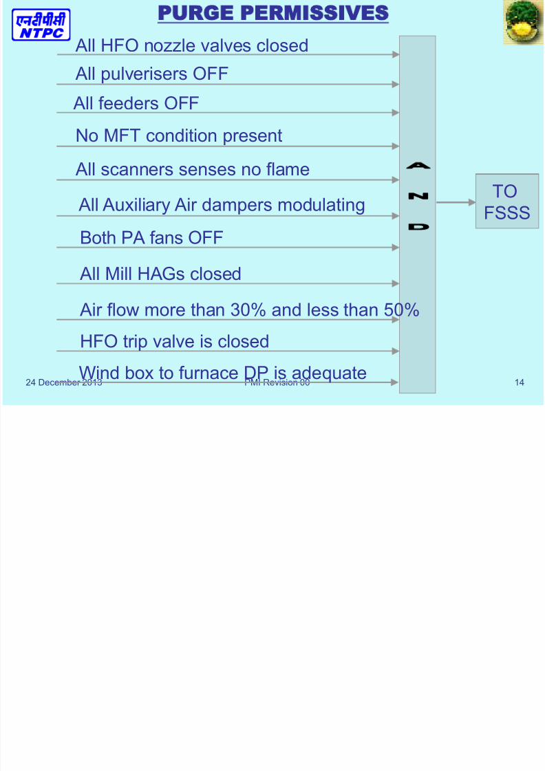
PURGE PERMISSIVES
TOFSSS
All HFO nozzle valves closed
All pulverisers OFF
All feeders OFF
No MFT condition present
All scanners senses no flame
All Auxiliary Air dampers modulating
Both PA fans OFF
All Mill HAGs closed
Air flow more than 30% and less than 50%
HFO trip valve is closed
Wind box to furnace DP is adequate

8/13/2019 FSSS LOGIC SYSTEM.ppt
http://slidepdf.com/reader/full/fsss-logic-systemppt 15/51
24 December 2013 PMI Revision 00 15
MASTER FUEL TRIP (MFT)• MFT or Boiler Trip means:
Complete isolation of all fuel to furnace under certainconditions
• Automatic Procedure:
All oil valves are given closing command
All mills and feeders are given trip command
All Primary Air (PA) Fans are given trip command
All Hot Air Gates (to mills) are given closing command
• Further Consequences: Turbine protection is initiated (to trip turbine)
All SH and RH spray valves are given closing command
All elevation SADC are given full open command
Furnace pressure & Air flow controls are set to manual

8/13/2019 FSSS LOGIC SYSTEM.ppt
http://slidepdf.com/reader/full/fsss-logic-systemppt 16/51
8/13/2019 FSSS LOGIC SYSTEM.ppt
http://slidepdf.com/reader/full/fsss-logic-systemppt 17/51
24 December 2013 PMI Revision 00 17
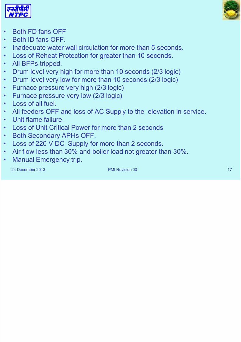
• Both FD fans OFF
• Both ID fans OFF.• Inadequate water wall circulation for more than 5 seconds.
• Loss of Reheat Protection for greater than 10 seconds.
• All BFPs tripped.
• Drum level very high for more than 10 seconds (2/3 logic)
• Drum level very low for more than 10 seconds (2/3 logic)
• Furnace pressure very high (2/3 logic)
• Furnace pressure very low (2/3 logic)
• Loss of all fuel.
• All feeders OFF and loss of AC Supply to the elevation in service.
• Unit flame failure.
• Loss of Unit Critical Power for more than 2 seconds• Both Secondary APHs OFF.
• Loss of 220 V DC Supply for more than 2 seconds.
• Air flow less than 30% and boiler load not greater than 30%.
• Manual Emergency trip.
B h FD f OFF

8/13/2019 FSSS LOGIC SYSTEM.ppt
http://slidepdf.com/reader/full/fsss-logic-systemppt 18/51
24 December 2013 PMI Revision 00 18
Both FD fans OFFBoth ID fans OFF
MFTRELAY
Air flow less than 30% and boiler load not greater than 30%
Loss of 220 V DC Supply for more than 2 seconds
Manual Emergency PB trip
Both Secondary APHs OFF
Loss of Unit Critical Power for more than 2 seconds
Unit flame failure
All feeders OFF and loss of AC Supply to the elevation in service
Loss of all fuel
Furnace pressure very low (2/3 logic)
Furnace pressure very high (2/3 logic)
Drum level very low for more than 10 seconds (2/3 logic)
Drum level very high for more than 10 seconds (2/3 logic)
All BFPs tripped
Loss of Reheat Protection for greater than 10 seconds
Inadequate water wall circulation for more than 5 seconds
8/13/2019 FSSS LOGIC SYSTEM.ppt
http://slidepdf.com/reader/full/fsss-logic-systemppt 19/51
24 December 2013 PMI Revision 00 19
Unit Logic
MFT consequences• Trips all mills
• Trips all feeders
• Trips PA fans
• Closes HFO trip valve
• Closes all elevation nozzle valves
• Close all HAGs

8/13/2019 FSSS LOGIC SYSTEM.ppt
http://slidepdf.com/reader/full/fsss-logic-systemppt 20/51

8/13/2019 FSSS LOGIC SYSTEM.ppt
http://slidepdf.com/reader/full/fsss-logic-systemppt 21/51
24 December 2013 PMI Revision 00 21
Oil Trip Valve operation logic
• This logic ensures that oil trip valve can be opened
after the purge cycle is completed and no MFTcondition is present, if the following conditions are
also satisfied.
– All nozzle valves are closed.
– HFO supply pressure is satisfactory.
– HFO header temperature is satisfactory.• Similarly, this logic ensures the closure of oil trip
valve in case of MFT.

8/13/2019 FSSS LOGIC SYSTEM.ppt
http://slidepdf.com/reader/full/fsss-logic-systemppt 22/51
24 December 2013 PMI Revision 00 22
Scanner air fans logic
• It monitors the scanner air duct to furnace DP
and ensures starting of scanner air fan - A or incase it fails to start, scanner air fan - B. This
logic gives an open command to scanner fan
outlet damper after starting the fan.
• Also, in case of both FD fans not running, it
ensures the scanner air emergency damper is
open.

8/13/2019 FSSS LOGIC SYSTEM.ppt
http://slidepdf.com/reader/full/fsss-logic-systemppt 23/51
24 December 2013 PMI Revision 00 23
Seal air fans logic
• Monitors seal air header to cold air duct DP
and ensures the starting of seal air fan - A or
B ( in case A does not start), provided at least
one PA fan is running.
• Gives an open command to seal air fandischarge damper once fan starts.

8/13/2019 FSSS LOGIC SYSTEM.ppt
http://slidepdf.com/reader/full/fsss-logic-systemppt 24/51
24 December 2013 PMI Revision 00 24
• Oil Elevation Logic
• AB/CD/EF/HJ*

8/13/2019 FSSS LOGIC SYSTEM.ppt
http://slidepdf.com/reader/full/fsss-logic-systemppt 25/51
8/13/2019 FSSS LOGIC SYSTEM.ppt
http://slidepdf.com/reader/full/fsss-logic-systemppt 26/51
24 December 2013 PMI Revision 00 26
8/13/2019 FSSS LOGIC SYSTEM.ppt
http://slidepdf.com/reader/full/fsss-logic-systemppt 27/51
24 December 2013 PMI Revision 00 27
Oil elevation logic
Start of oil elevations AB,CD,EF and GH
• Sequential operation with start command
• Corner1,corner3,corner2 and corner4
• Gun advance,igniter advance
• Spark,atomizing valve open,oil valve open
• Sensing of discriminatory flame
• Retract of igniter

8/13/2019 FSSS LOGIC SYSTEM.ppt
http://slidepdf.com/reader/full/fsss-logic-systemppt 28/51
24 December 2013 PMI Revision 00 28
Oil elevation logic
Stop of oil elevation
• Closure of oil valve,opening of scavenge valve
• Igniter advance and sparking
• Closure of atomizing valve and scavenge valve
• Retract of igniter and gun
8/13/2019 FSSS LOGIC SYSTEM.ppt
http://slidepdf.com/reader/full/fsss-logic-systemppt 29/51
8/13/2019 FSSS LOGIC SYSTEM.ppt
http://slidepdf.com/reader/full/fsss-logic-systemppt 30/51
24 December 2013 PMI Revision 00 30
A particular corner takes the start command only
if the following conditions are satisfied:-
• The particular corner oil gun engaged feedback is
available.
• The steam scavenge valve is closed for the
particular corner.
8/13/2019 FSSS LOGIC SYSTEM.ppt
http://slidepdf.com/reader/full/fsss-logic-systemppt 31/51
24 December 2013 PMI Revision 00 31
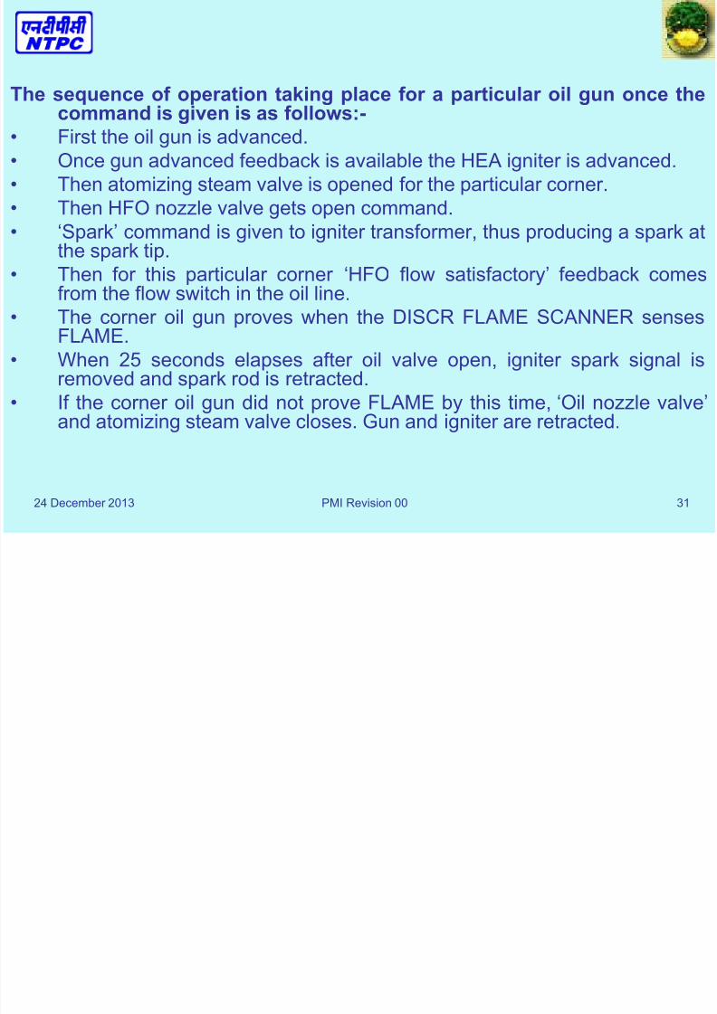
The sequence of operation taking place for a particular oil gun once thecommand is given is as follows:-
• First the oil gun is advanced.
• Once gun advanced feedback is available the HEA igniter is advanced.
• Then atomizing steam valve is opened for the particular corner.
• Then HFO nozzle valve gets open command.
• „Spark‟ command is given to igniter transformer, thus producing a spark at
the spark tip.• Then for this particular corner „HFO flow satisfactory‟ feedback comes
from the flow switch in the oil line.
• The corner oil gun proves when the DISCR FLAME SCANNER sensesFLAME.
• When 25 seconds elapses after oil valve open, igniter spark signal is
removed and spark rod is retracted.• If the corner oil gun did not prove FLAME by this time, „Oil nozzle valve‟
and atomizing steam valve closes. Gun and igniter are retracted.
8/13/2019 FSSS LOGIC SYSTEM.ppt
http://slidepdf.com/reader/full/fsss-logic-systemppt 32/51
24 December 2013 PMI Revision 00 32
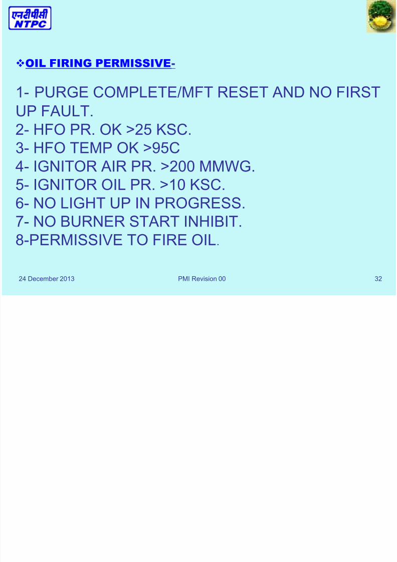
OIL FIRING PERMISSIVE-
1- PURGE COMPLETE/MFT RESET AND NO FIRST
UP FAULT.
2- HFO PR. OK >25 KSC.
3- HFO TEMP OK >95C
4- IGNITOR AIR PR. >200 MMWG.
5- IGNITOR OIL PR. >10 KSC.
6- NO LIGHT UP IN PROGRESS.7- NO BURNER START INHIBIT.
8-PERMISSIVE TO FIRE OIL.
8/13/2019 FSSS LOGIC SYSTEM.ppt
http://slidepdf.com/reader/full/fsss-logic-systemppt 33/51
24 December 2013 PMI Revision 00 33
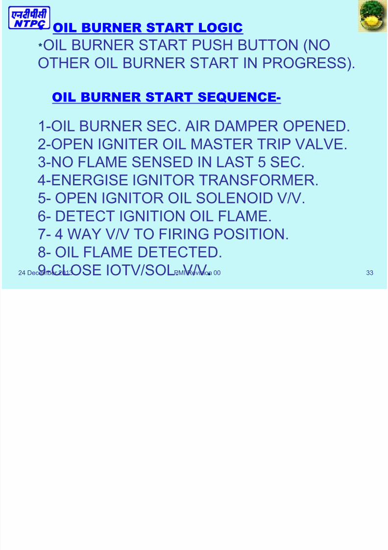
• OIL BURNER START LOGIC
*OIL BURNER START PUSH BUTTON (NO
OTHER OIL BURNER START IN PROGRESS).
OIL BURNER START SEQUENCE-
1-OIL BURNER SEC. AIR DAMPER OPENED.
2-OPEN IGNITER OIL MASTER TRIP VALVE.
3-NO FLAME SENSED IN LAST 5 SEC.
4-ENERGISE IGNITOR TRANSFORMER.
5- OPEN IGNITOR OIL SOLENOID V/V.6- DETECT IGNITION OIL FLAME.
7- 4 WAY V/V TO FIRING POSITION.
8- OIL FLAME DETECTED.
9-CLOSE IOTV/SOL. V/V.
8/13/2019 FSSS LOGIC SYSTEM.ppt
http://slidepdf.com/reader/full/fsss-logic-systemppt 34/51
24 December 2013 PMI Revision 00 34
• Coal Elevation Logic
• A/B/C/D/F

8/13/2019 FSSS LOGIC SYSTEM.ppt
http://slidepdf.com/reader/full/fsss-logic-systemppt 35/51
24 December 2013 PMI Revision 00 35

8/13/2019 FSSS LOGIC SYSTEM.ppt
http://slidepdf.com/reader/full/fsss-logic-systemppt 36/51
24 December 2013 PMI Revision 00 36
8/13/2019 FSSS LOGIC SYSTEM.ppt
http://slidepdf.com/reader/full/fsss-logic-systemppt 37/51
24 December 2013 PMI Revision 00 37
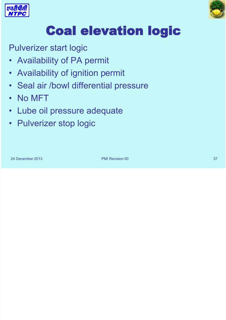
Coal elevation logic
Pulverizer start logic
• Availability of PA permit
• Availability of ignition permit
• Seal air /bowl differential pressure
• No MFT
• Lube oil pressure adequate
• Pulverizer stop logic

8/13/2019 FSSS LOGIC SYSTEM.ppt
http://slidepdf.com/reader/full/fsss-logic-systemppt 38/51
24 December 2013 PMI Revision 00 38
Coal elevation logic
Feeder start logic
• Pulverizer on
• Outlet temperature adequate
• Speed demand minimum
• No MFT
• Feeder stop logic
• Had/cad logic

8/13/2019 FSSS LOGIC SYSTEM.ppt
http://slidepdf.com/reader/full/fsss-logic-systemppt 39/51
24 December 2013 PMI Revision 00 39
COAL ELEVATION LOGIC
PULVERISER LOGIC
• This logic takes the count of total no. of pulverisers in
service at any point of time, the no. of FD Fans andPA fans in service. With PA Fan „ON‟ and PA Header
Pressure adequate (>560 mmwcl), it gives “PA
permit” to start the Pulverizer. In case of PA Header
Pressure going low-low or PA/ FD fans trips, itensures the shut down of Pulverizers from top
elevation to bottom elevation in a timed sequence.
8/13/2019 FSSS LOGIC SYSTEM.ppt
http://slidepdf.com/reader/full/fsss-logic-systemppt 40/51
24 December 2013 PMI Revision 00 40
• Each mill can be taken in to service manually or
automatically. Auto manual selection push button
is available on FSSS console for each mill.
Initially, “Pulverizer Ignition Permit” signal mustbe established for the mill to start. Other condition
required to be established for starting the mill are
as follows:-
8/13/2019 FSSS LOGIC SYSTEM.ppt
http://slidepdf.com/reader/full/fsss-logic-systemppt 41/51
24 December 2013 41
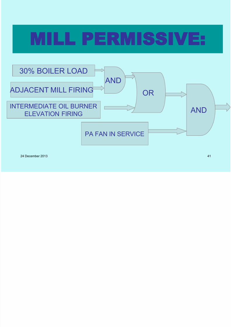
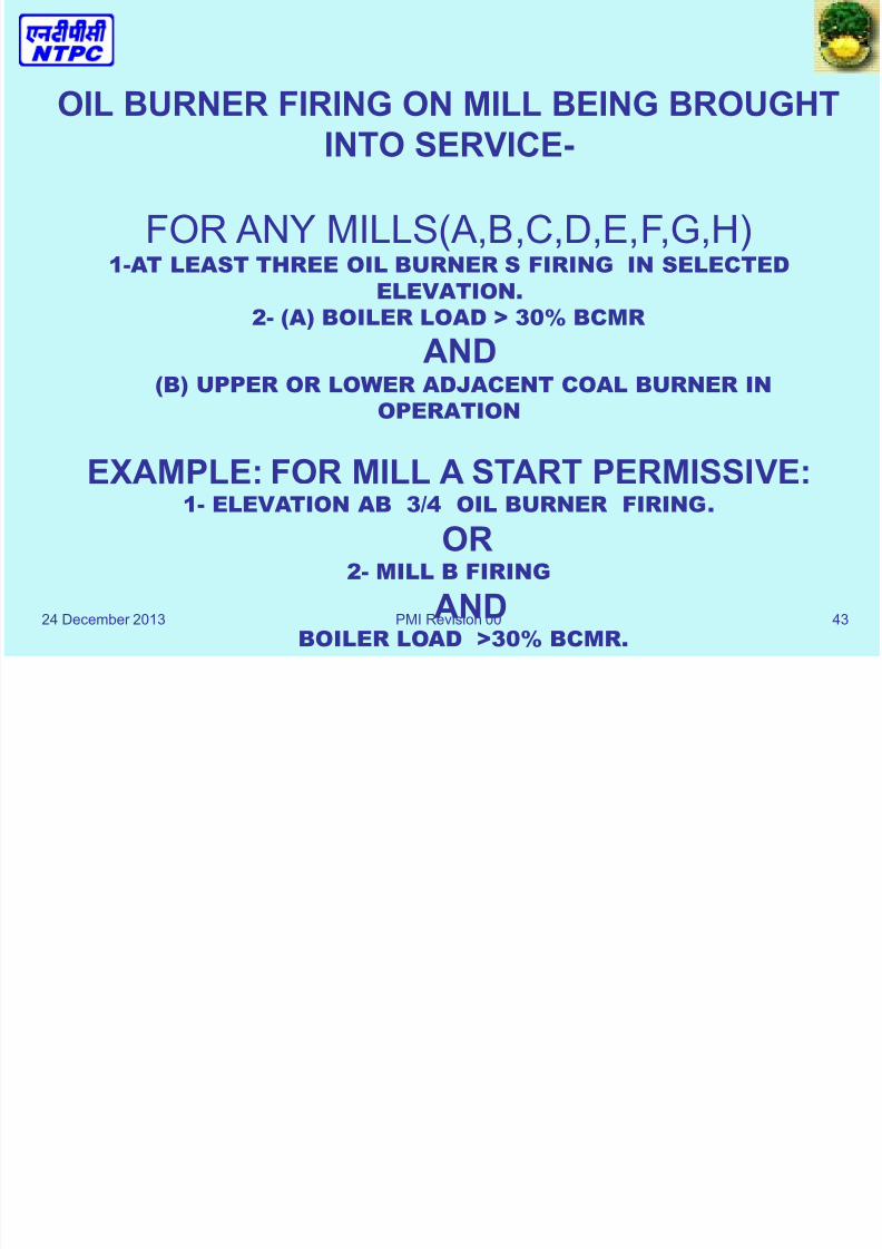
MILL PERMISSIVE:
INTERMEDIATE OIL BURNER
ELEVATION FIRING
OR
30% BOILER LOAD
ADJACENT MILL FIRING
PA FAN IN SERVICE
AND
AND
8/13/2019 FSSS LOGIC SYSTEM.ppt
http://slidepdf.com/reader/full/fsss-logic-systemppt 42/51
24 December 2013 PMI Revision 00 42
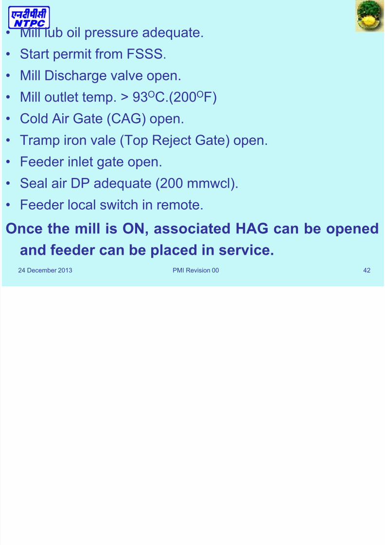
• Mill lub oil pressure adequate.
• Start permit from FSSS.
• Mill Discharge valve open.
• Mill outlet temp. > 93OC.(200OF)
• Cold Air Gate (CAG) open.
• Tramp iron vale (Top Reject Gate) open.
• Feeder inlet gate open.
• Seal air DP adequate (200 mmwcl).
• Feeder local switch in remote.
Once the mill is ON, associated HAG can be opened
and feeder can be placed in service.
8/13/2019 FSSS LOGIC SYSTEM.ppt
http://slidepdf.com/reader/full/fsss-logic-systemppt 43/51

8/13/2019 FSSS LOGIC SYSTEM.ppt
http://slidepdf.com/reader/full/fsss-logic-systemppt 44/51
24 December 2013 PMI Revision 00 44
FOR B,D,F MILL A) AT LEAST 3 OIL BURNERS FIRING IN THE BURNER
GROUP ABOVE
AND (B) ADJACENT COAL BURNER ABOVE IN OPERATION
AND(C) THIS ELEVATION IS HIGHEST IN THE BURNER GROUP.
EXAMPLE- FOR MILL B START PERMISSIVE-
(1) ELEVATION AB 3 / 4 OIL BURNER ARE I/ S .
OR(2) MILL A FIRING OR MILL C FIRING
AND
BOILER LOAD > 30% OF BCMR.OR
(3) MILL C FIRING
ANDELEVATION CD 3 / 4 OIL BURNER ARE I/S.
* NOTE THAT B ELEVATION IS HIGHEST IN THE BURNER GROUP AB.
8/13/2019 FSSS LOGIC SYSTEM.ppt
http://slidepdf.com/reader/full/fsss-logic-systemppt 45/51
24 December 2013 PMI Revision 00 45
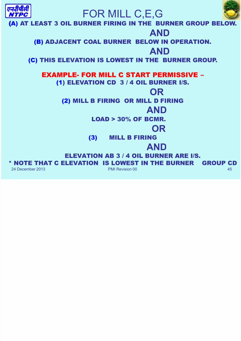
FOR MILL C,E,GA) AT LEAST 3 OIL BURNER FIRING IN THE BURNER GROUP BELOW.
AND
(B) ADJACENT COAL BURNER BELOW IN OPERATION.AND
(C) THIS ELEVATION IS LOWEST IN THE BURNER GROUP.
EXAMPLE- FOR MILL C START PERMISSIVE – (1) ELEVATION CD 3 / 4 OIL BURNER I/S.
OR(2) MILL B FIRING OR MILL D FIRING
AND LOAD > 30% OF BCMR.
OR(3) MILL B FIRING
AND
ELEVATION AB 3 / 4 OIL BURNER ARE I/S.
* NOTE THAT C ELEVATION IS LOWEST IN THE BURNER GROUP CD

8/13/2019 FSSS LOGIC SYSTEM.ppt
http://slidepdf.com/reader/full/fsss-logic-systemppt 46/51
24 December 2013 46
MILL PERMISSIVE:30% BOILER LOAD
ADJACENT MILL FIRING
PA FAN IN SERVICE
INTERMEDIATE OIL BURNER
ELEVATION FIRING
ANDOR
AND
8/13/2019 FSSS LOGIC SYSTEM.ppt
http://slidepdf.com/reader/full/fsss-logic-systemppt 47/51
24 December 2013 47
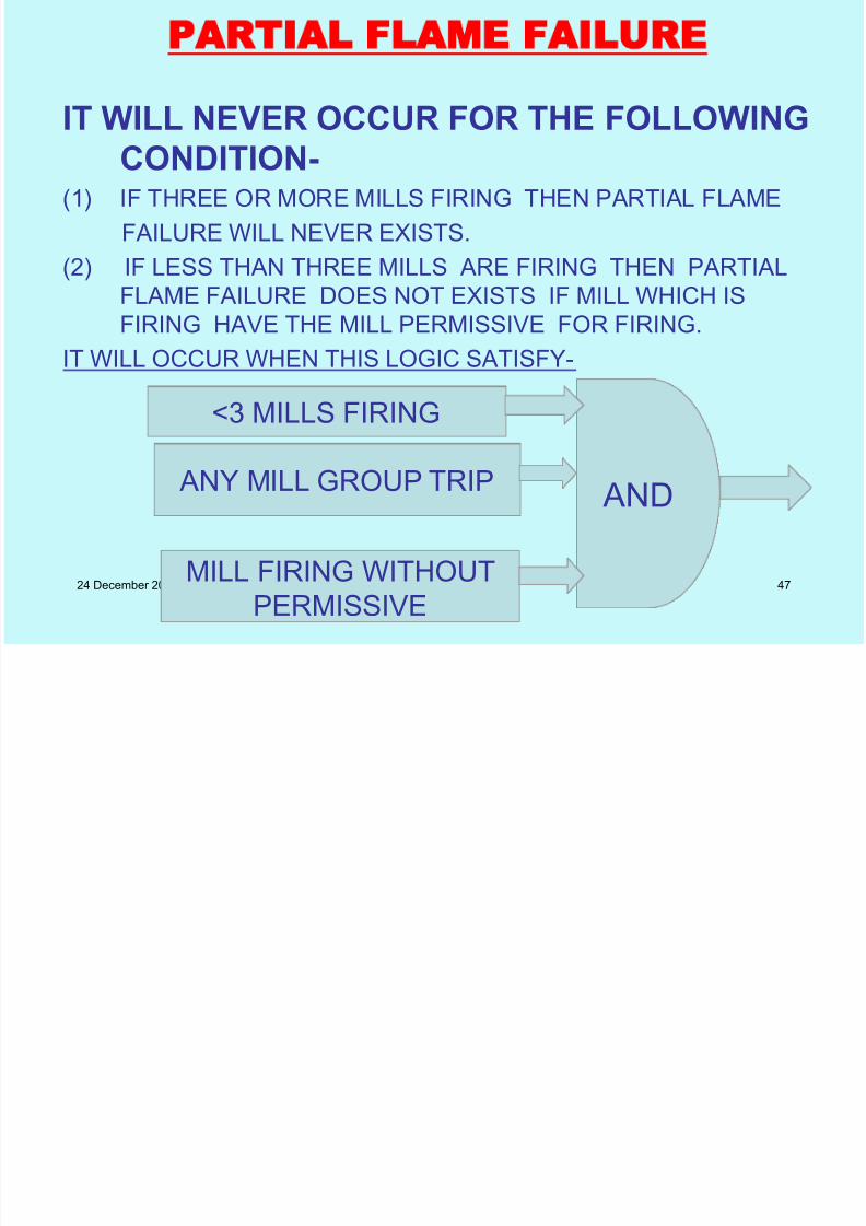
PARTIAL FLAME FAILURE
IT WILL NEVER OCCUR FOR THE FOLLOWING
CONDITION-(1) IF THREE OR MORE MILLS FIRING THEN PARTIAL FLAME
FAILURE WILL NEVER EXISTS.
(2) IF LESS THAN THREE MILLS ARE FIRING THEN PARTIAL
FLAME FAILURE DOES NOT EXISTS IF MILL WHICH IS
FIRING HAVE THE MILL PERMISSIVE FOR FIRING.
IT WILL OCCUR WHEN THIS LOGIC SATISFY-
<3 MILLS FIRING
ANY MILL GROUP TRIP
MILL FIRING WITHOUT
PERMISSIVE
AND

8/13/2019 FSSS LOGIC SYSTEM.ppt
http://slidepdf.com/reader/full/fsss-logic-systemppt 48/51
24 December 2013 PMI Revision 00 48
VOTING OF ELEVATION –
VOTING IN AB ELEVATION WILL BE AVAILABLE
(1) MILL A FEEDER OR MILL B FEEDER I/S.
AND ELEVATION AB 2 / 4 FLAMES IN.
INTRLOCKED WITH ( ALL BURNER IN AB ELEVATION
SATISFACTORY S/D OR 3 / 4 OIL BURNER IN THAT ELEVATION
ARE I/S.)
(2) VOTING IN BC ELEVATION WILL BE AVAILABLE-
MILL B FEEDER OR MILL C FEEDER I/S.AND
ELEVATION B 2 / 4 FLAMES IN.
VOTING WIL NOT BE AVAILABLE – (1) BOTH FEEDERS ON BURNER ELEVATION ARE NOT I/S.
OR
(2) 2/4 FLAME ARE NOT SENSED INTERLOCKED WITH 3 / 4 OILBURNER ARE NOT FIRING.
OR
(3) OIL GUN IN THAT ELEVATION NOT SATISFACTORLY
SHUTDOWN INTROLOCKED WITH 3 / 4 OIL BURNER IN THAT
ELEVATION NOT FIRING.
Feeder start Logic
8/13/2019 FSSS LOGIC SYSTEM.ppt
http://slidepdf.com/reader/full/fsss-logic-systemppt 49/51
24 December 2013 PMI Revision 00 49
Feeder start Logic
• Feeder start command is given from FSSSElevation Logic only. This command is
continuously required to keep the feeder in
service. Feeder speed demand minimum,Pulverizer ON, pulverizer outlet temp > 130OF,
HAG open and no MFT are the important
conditions required to give the feeder start
command from FSSS.

8/13/2019 FSSS LOGIC SYSTEM.ppt
http://slidepdf.com/reader/full/fsss-logic-systemppt 50/51
24 December 2013 PMI Revision 00 50
• In case of pulveriser power high, bowl DP High or
feeder OFF command, feeder speed demand is
driven to minimum.
• Release feeder to Auto Signal is also coming from
FSSS. All of the above conditions are present and
feeder is not ON for more than 50 seconds, release
signal for auto is available.

8/13/2019 FSSS LOGIC SYSTEM.ppt
http://slidepdf.com/reader/full/fsss-logic-systemppt 51/51
Related Documents