FV4C Performancet Series Fan Coil Sizes 002 Thru 006 Product Data PREMIUM ENVIRONMENTALLY SOUND FAN COIL The FV4C is the premium air handler combining the proven technology of Carrier fan coils with environmentally sound Purone refrigerant. The FV4C achieves an operational advantage when the ECM (Electronically Commutated Motor) is combined with a Carrier Performancet heat pump with Purone refrigerant. With attention to quiet, efficient, and comfortable operation, Carrier has developed a new benchmark for superior indoor comfort and control. ArmorCoatt provides a tin plating of the indoor coil’s copper hairpins. This creates a barrier between the corrosion--causing elements and the coil. Carrier’s heat pump and air conditioning systems now feature Purone refrigerant (R--410A), the chlorine--free refrigerant that is the future for the residential heating and cooling industry. The FV4C using Purone refrigerant maximizes performance for environmentally sound systems. In addition to environmental safety, these systems are 30 to 40% more efficient than standard heating and cooling systems, thereby combining excellence in efficiency and environmental safety. The FV4C provides these benefits due to Carrier’s command of ECM technology. These motors are extremely efficient at all speeds, and enable the FV4C to operate at the correct speed to deliver airflow precisely, ensuring proper performance across a wide range of duct static pressures. This adaptive efficiency also makes installation quality easier to achieve for today’s demanding homeowner. Carrier’s command of ECM technology may be most evident in the comfort advantages that ECM can deliver. Operation set up steps on the Easy Selectt Board provide the installing technician with alternatives to maximize comfort and efficiency. For true indoor comfort, the homeowner can achieve command of both temperature and humidity in cooling and heating modes. Another feature which sets the FV4C apart is the factory--installed TXV, which enhances efficiency and provides compressor protecting operation at all recommended conditions. Grooved copper tubing, louvered aluminum fins, and the large face areas of the FV4C refrigerant coils also provide superior efficiency, for high SEER and HSPF performance. Carrier leads the way in condensate control, a hallmark of these multipoise fan coils. All of these featured components are protected within a rugged, prepainted metal cabinet lined with super thick, high density insulation. For neat, high quality installations the unit exterior features sweat refrigerant connections for simple leak free performance, and multiple electrical entry for both high and low voltage service. For superior technology and unmatched comfort, the environmentally sound and efficient FV4C can’t be beat.

Welcome message from author
This document is posted to help you gain knowledge. Please leave a comment to let me know what you think about it! Share it to your friends and learn new things together.
Transcript

FV4CPerformancet Series Fan CoilSizes 002 Thru 006
Product Data
PREMIUM ENVIRONMENTALLYSOUND FAN COIL
The FV4C is the premium air handler combining the proventechnology of Carrier fan coils with environmentally soundPurone refrigerant. The FV4C achieves an operational advantagewhen the ECM (Electronically Commutated Motor) is combinedwith a Carrier Performancet heat pump with Purone refrigerant.
With attention to quiet, efficient, and comfortable operation,Carrier has developed a new benchmark for superior indoorcomfort and control. ArmorCoatt provides a tin plating of theindoor coil’s copper hairpins. This creates a barrier between thecorrosion--causing elements and the coil.
Carrier’s heat pump and air conditioning systems now featurePurone refrigerant (R--410A), the chlorine--free refrigerant that isthe future for the residential heating and cooling industry. TheFV4C using Purone refrigerant maximizes performance forenvironmentally sound systems. In addition to environmentalsafety, these systems are 30 to 40% more efficient than standardheating and cooling systems, thereby combining excellence inefficiency and environmental safety.
The FV4C provides these benefits due to Carrier’s command ofECM technology. These motors are extremely efficient at allspeeds, and enable the FV4C to operate at the correct speed todeliver airflow precisely, ensuring proper performance across awide range of duct static pressures. This adaptive efficiency alsomakes installation quality easier to achieve for today’s demandinghomeowner.
Carrier’s command of ECM technology may be most evident in thecomfort advantages that ECM can deliver. Operation set up stepson the Easy Selectt Board provide the installing technician withalternatives to maximize comfort and efficiency. For true indoorcomfort, the homeowner can achieve command of bothtemperature and humidity in cooling and heating modes.
Another feature which sets the FV4C apart is the factory--installedTXV, which enhances efficiency and provides compressorprotecting operation at all recommended conditions. Groovedcopper tubing, louvered aluminum fins, and the large face areas ofthe FV4C refrigerant coils also provide superior efficiency, for highSEER and HSPF performance. Carrier leads the way in condensatecontrol, a hallmark of these multipoise fan coils. All of thesefeatured components are protected within a rugged, prepaintedmetal cabinet lined with super thick, high density insulation. Forneat, high quality installations the unit exterior features sweatrefrigerant connections for simple leak free performance, andmultiple electrical entry for both high and low voltage service.
For superior technology and unmatched comfort, theenvironmentally sound and efficient FV4C can’t be beat.

2
FEATURESEnvironmentally Sound Refrigerant TechnologyS Puronr, chlorine--free non--ozone depleting refrigerant
S Thermostatic Expansion Valve (TXV) designed to maximize performance with Puronr refrigerant
Energy Efficient OperationS Electronically Commutating Motor (ECM) operates efficiently at all speeds
S Maximizes efficiency of heating and cooling systems
S Ultra low power consumption during fan only operation
Indoor Weather ControlS Warm, comfortable heating air temperatures
S Unmatched humidity control, especially with Carrier’s Thermidistatt Control
Airflow and Sound TechnologyS Diffuser air discharge section for high airflow efficiency and quiet, smooth operation
S High duct static capability
S Unique cabinet design that meets new stringent regulations for air leakage. Meets requirements of a 2% cabinet leakage rate when tested at
1.0 inches of static pressure
Condensate Control and Disposal TechnologyS Minimal standing waterless microbial growth for improved IAQ and reduced condensate line clogging and related condensate leakage
S Condensate fittings relocated away from turbulent airflow patterns at the blower entrance for improved condensate control performance
S Overflow feature for slope coil units allows condensate to exit the unit without damage to product under clogged primary and secondary
line conditions
S Tested for condensate disposal at conditions much more severe than those required by AHRI
S Primary and secondary drain connections to comply with HUD
S All pans constructed of an injection molded glass--filled polycarbonate engineered resin material, with brass drain connections.
S High density, super thick cabinetry insulation with vapor barrier
S Pre--painted galvanized sheet metal cabinet
Heat Transfer TechnologyS Grooved copper tubing
S Lanced sine wave aluminum fins
S Discreet refined counter--flow refrigerant circuitry
S Bi--flow hard shut--off TXV metering device
S ArmorCoatt coil protection available
Quality Assisting, Ease of Installation and Service FeaturesS All units multipoise
S Provision made for suspending from roof or ceiling joints
S Modular cabinet on 003 thru 006 units
S Sweat connections for leak free service
S Multiple electrical entry for application flexibility (high and low voltage)
S Low voltage terminal strip, to safely hold connections within the cabinet
S Inspection plate on A--coil models for quick coil cleanliness inspection
S Cabinet construction features innovations designed to prevent cabinet sweating
Controls and Electrical FeaturesS Easy Selectt Board to maximize comfort, efficiency, and safe heater airflow operation
S Easy plug connection provided for quick installation of accessory heater packages
S 40VA 208/230v transformer
S Replaceable 5--amp blade--type auto fuse protects against transformer secondary short
Filter FeaturesS Factory supplied filter
S Cleanable polyester filter media
S Filter “springs” out for easy access -- no tools required
S Newly improved filter rack area -- filter door insulation added for an improved air seal
FV4C

3
MODEL NUMBER NOMENCLATURE
1 2 3 4 5 6 7 8 9 10 11 12F V 4 C N B 0 0 3 0 0 0
Product Heating SizeF = Fan Coil T00 = ArmorCoatt
000 = No HeatType 005 = 5 kWV = Puronr Refrigerant 075 = 7.5 kW
008 = 8 kWPosition 010 = 10 kW4 = Multipoise 011 = 11 kW
015 = 15 kWSeriesC Capacity
002 = 18---36,000Electrical 003 = 24---42,000N = 208/230v, 1ph---60 Hz 005 = 30---48,000
006 = 30---60,000Cabinet/InsulationB = ModularF = Single piece
the environmentally sound refrigerant
Use of the AHRI CertifiedTM Mark indicates amanufacturer’s participation in the program For verification of certification for individual products, go to www.ahridirectory.org.
SPECIFICATIONSMODEL FV4C 002 003 005 006COILRefrigerant Metering Device Puronr Refrigerant (R---410A)TXV Size 2 Ton 3 Ton 4 TonRows/Fins Per In. 3 / 14.5Face Area (Sq Ft) 3.46 5.93 7.42Configuration A Slope ABLOWER & MOTORAir Discharge Upflow, Downflow, Horizontal
CFM (Nominal Clg/Htg)
525 / 470700 / 630875 / 7851050 / 945
700 / 630875 / 7851050 / 9451225 / 1100
875 / 7851050 / 9451225 / 11001400 / 1260
1050 / 9451225 / 11001400 / 12601750 / 1575
Motor HP (ECM) 1/2 3/4FILTER CLEANABLE
21---1/2” (546 mm) by 16---3/8” (417 mm) 19---7/8” (505 mm) 23---5/16” (585 mm)CABINET CONFIGURATION OPTIONS
1 Piece 1 Piece or Modular Modular
FV4C

4
DIM
EN
SIO
NS
UNITSIZE
AB
CD
EH
Jin
mm
inmm
inmm
inmm
inmm
inmm
inmm
FV4CNB003
53---7/16
1357
21---1/8
537
19---1/4
489
19---1/8
486
19---3/16
487
28---5/16
735
19483
FV4CNB005
53---7/16
1357
21---1/8
537
19---1/4
489
19---1/8
486
19---3/16
487
28---5/16
735
——
FV4CNB006
59---3/16
1503
24---11/16
627
22---3/4
578
22---11/16
576
25---1/4
642
34---1/16
865
——
FV4CNF002
42---11/16
1084
17---5/8
448
15---3/4
400
15---5/8
397
10---3/4
273
——
——
FV4CNF003
53---7/16
1357
21---1/8
537
19---1/4
489
19---1/8
486
19---3/16
487
——
19483
FV4CNF005
53---7/16
1357
21---1/8
537
19---1/4
489
19---1/8
486
19---1/2
495
——
——
FV4C

5
DIM
EN
SIO
NS
UNITSIZE
FG
COILTYPE
SHIPPINGWEIGHT
inmm
inmm
lbkg
FV4CNB003
26---15/16
684
27---1/2
699
SLOPE
150
68FV4CNB005
26---15/16
684
27---1/2
699
A172
78FV4CNB006
32---15/16
837
32---5/8
829
A207
94FV4CNF002
18---9/16
471
18---1/4
464
A135
61FV4CNF003
26---15/16
684
27---1/2
699
SLOPE
150
68FV4CNF005
27---1/4
692
26---15/16
684
A172
78
FV4C

6
PERFORMANCE DATAFV4C ADVANCED FAN COIL AIRFLOW DELIVERY CHART (CFM)
OPERATING MODE
UNIT SIZEOUTDOORUNIT
CAPACITY
SINGLE—SPEEDAPPLICATION TWO—SPEED APPLICATION FAN ONLY
NominalA/CCooling
A/CCoolingDehumidity
High Speed Low Speed
Lo Med HighNominalA/CCooling
A/CCoolingDehumidity
NominalA/CCooling
A/CCoolingDehumidity
002
018 525 420 — — — — 350 420 525024 700 560 700 560 560 450 350 560 700030 875 700 — — — — 440 700 875036 1050 840 1050 840 840 670 525 840 1050
003
024 700 560 700 560 560 450 415 560 700030 875 700 — — — — 440 700 875036 1050 840 1050 840 840 670 525 840 1050042 1225 980 — — — — 610 980 1225
005
030 875 700 — — — — 440 700 875036 1050 840 1050 840 840 670 525 840 1050042 1225 980 — — — — 610 980 1225048 1400 1120 1400 1120 1120 895 700 1120 1400
006
036 1050 840 1050 840 840 670 540 840 1050042 1225 980 — — — — 610 980 1225048 1400 1120 1400 1120 1120 895 700 1120 1400060 1750 1400 1750 1400 1400 1120 875 1400 1750
NOTES:1. The above airflows result with the AC, HP CFM ADJUST select jumper set on NOM.2. Air flow can be adjusted +15% or ---10% by selecting HI or LO respectively for all modes except fan only.3. Dry coil at 230 volts and with 10kW heater and filter installed.4. Airflows shown are at standard air conditions.
*Consult ARI ratings before matching outdoor unit with FV4C fan coil.
FV4C ADVANCED FAN COIL AIRFLOW DELIVERY CHART (CFM)OPERATING MODE
UNIT SIZEOUTDOORUNIT
CAPACITY
SINGLE—SPEEDAPPLICATION TWO—SPEED APPLICATION FAN ONLY
Heat PumpComfort
Heat PumpEfficiency
High Speed Low SpeedLo Med HighHeat Pump
ComfortHeat PumpEfficiency
Heat PumpComfort
Heat PumpEfficiency
002
018 470 525 — — — — 350 380 470024 630 700 630 700 505 560 350 505 630030 785 875 — — — — 390 630 785036 945 1050 945 1050 755 840 470 755 945
003
024 630 700 630 700 415 560 415 505 630030 785 875 — — — — 415 630 785036 945 1050 945 1050 755 840 470 755 945042 1100 1225 — — — — 550 880 1100
005
030 785 875 — — — — 425 630 785036 945 1050 945 1050 755 840 470 755 945042 1100 1225 — — — — 550 880 1100048 1260 1400 1260 1400 1010 1120 630 1010 1260
006
036 945 1050 945 1050 755 840 540 755 945042 1100 1225 — — — — 550 880 1100048 1260 1400 1260 1400 1010 1120 630 1010 1260060 1575 1750 1575 1750 1260 1400 785 1260 1575
NOTES:1. The above airflows result with the AC, HP CFM ADJUST select jumper set on NOM.2. Air flow can be adjusted +15% or ---10% by selecting HI or LO respectively for all modes except fan only.3. Dry coil at 230 volts and with 10kW heater and filter installed.4. Airflows shown are at standard air conditions.
FV4C

7
PERFORMANCE DATA (cont)AIRFLOW DELIVERY CHART (CFM) — ELECTRIC HEATING MODES
FANUNIT SIZE
OUTDOORUNIT
CAPACITYBTUH
ELECTRIC HEATER kW RANGE
0---5 0---10 0---15 0---20
Lo Nom High Lo Nom High Lo Nom High Lo Nom High
002
18,000 625 625 625 675 675 --- --- --- --- --- --- ---24,000 650 725 835 --- 725 835 875 875 875 --- --- ---30,000 815 905 1040 --- 905 1040 900 900 1040 1100 1100 110036,000 980 1085 1250 980 1085 1250 980 1085 1250 1100 1100 1250
003
24,000 675 725 835 875 875 --- --- --- --- --- --- ---30,000 815 905 1040 875 905 1040 1100 1100 1100 --- --- ---36,000 980 1085 1250 980 1085 1250 1100 1100 1250 1225 1225 125042,000 1140 1270 1460 1140 1270 1460 1140 1270 1460 1225 1270 1460
FANUNIT SIZE
OUTDOORUNIT
CAPACITYBTUH
ELECTRIC HEATER kW RANGE
0---10 0---15 0---20 0---30
Lo Nom High Lo Nom High Lo Nom High Lo Nom High
005
30,000 975 975 1040 1100 1100 1100 --- --- --- --- --- ---36,000 980 1085 1250 1100 1100 1250 1250 1250 1250 --- --- ---42,000 1140 1270 1460 1140 1270 1460 1250 1270 1460 --- --- ---48,000 1305 1450 1665 1305 1450 1665 1305 1450 1665 1500 1500 1665
006
36,000 1100 1100 1250 1350 1350 1350 --- --- --- --- --- ---42,000 1140 1270 1460 1350 1350 1460 1525 1525 1525 --- --- ---48,000 1305 1450 1665 1350 1450 1665 1525 1525 1665 1750 1750 175060,000 1630 1810 2085 1630 1810 2085 1630 1810 2085 1750 1810 2085
NOTE: Lo, NOM, and HI refer to AC, HP CFM ADJUST selection.--- Airflow not recommended for heater/system size.
MINIMUM CFM FOR ELECTRIC HEATER APPLICATION
FAN COIL UNIT HEAT PUMP UNITSIZE
CFMHEATER SIZE kW
5 8, 9, 10 15 18, 20 24, 30
002
Heater Only 625 625 725 875 —018 625 625 — — —024 650 725 875 — —030 800 875 875 1040 —036 970 970 970 1040 —
003
Heater Only 675 700 1050 1050 —024 675 875 — — —030 800 875 1100 — —036 975 975 1100 1225 —042 1125 1125 1125 1225 —
005
Heater Only 675 700 1050 1050 1400018 800 875 1100 — —036 975 975 1100 1225 —042 1125 1125 1125 1225 —048 1305 1305 1305 1305 1400
006
Heater Only 1050 1050 1050 1050 1750018 1100 1100 1350 1350 —042 1125 1125 1350 1350 —048 1300 1300 1350 1465 1750060 1625 1625 1625 1750 1750
NOTES:1. Heater Only---Air conditioner with electric heater application.2. These airflows are minimum acceptable airflows as UL listed. Actual airflow delivered will be per airflow delivery chart for Electric Heating Modes.
FV4C

8
PERFORMANCE DATA (cont)
00
0.1
0.2
0.3
0.4
0.5
0.6
0.7
0.1 0.2 0.3 0.4 0.5 0.6
RETURN STATIC PRESSURE, IN.W.C.
SU
PP
LY S
TA
TIC
PR
ES
SU
RE
, IN
.W.C
.
TOO HIGHRETURN STATICPRESSURE(DIFFICULT TO MAKETRAP)
ACCEPTABLE RANGE
A02296
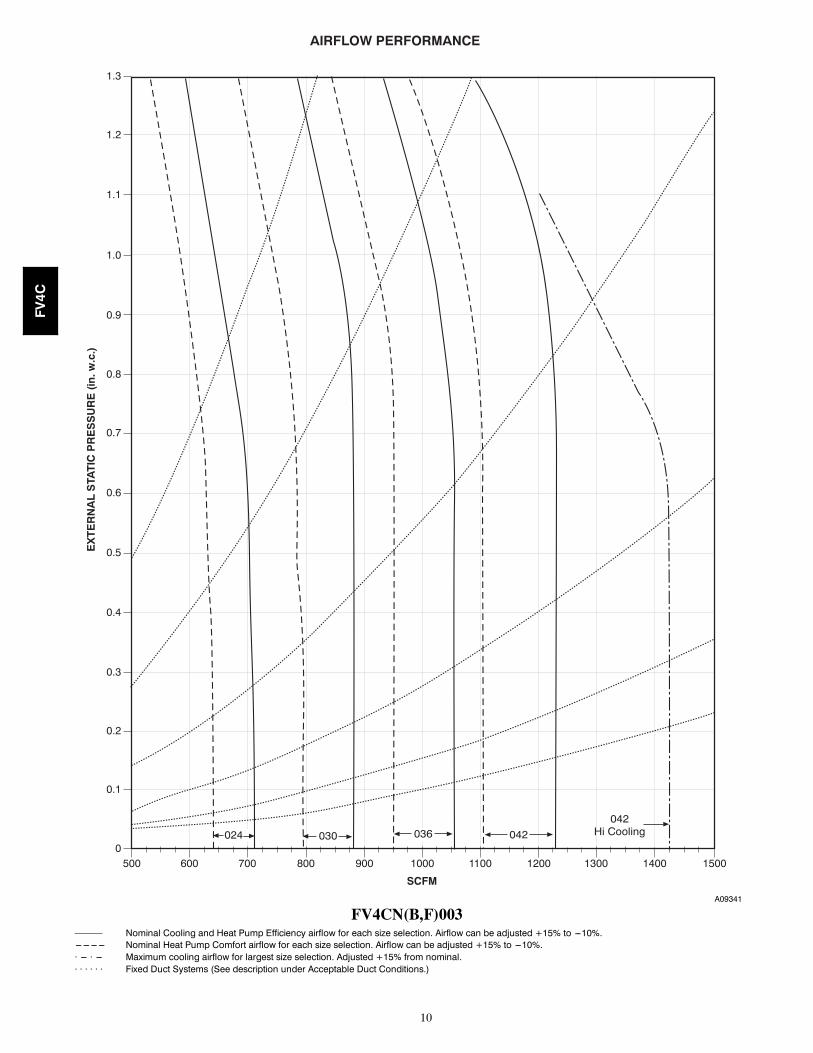
ACCEPTABLE DUCT CONDITIONSFor satisfactory operation (specifically making dry secondary trap),subject fan coils must be installed with duct systems which fallwithin the “Acceptable Range” illustrated above.
The airflow performance charts for the FV4C fan coil depictnominal airflow delivery for heating and cooling mode operationversus duct system static pressure drop. Cooling mode operation isshown as solid vertical lines for all 4 system size selections.Heating mode operation for the 4 system size selections are shownas dashed vertical lines.
The dotted curved lines are static pressure drop characteristics forseveral fixed--duct systems. These lines can be used to predict the
system static pressure drop at any airflow given the actual drop at 1known point.
For example, a duct system is designed for 0.15 in. water column(in. w.c.) drop at 1200 CFM. The FV4CNF005 operating atnominal cooling airflow would deliver 1050 CFM with a ductsystem drop of 0.11 in. w.c.. (See point 1.) On the same ductsystem, the FV4CNF005 operating at nominal heating airflowwould deliver 945 CFM with a duct system drop of 0.09 in. w.c.(See point 2.)
This example is but one of many possible duct system designs. TheFV4CNF005 will deliver the above airflows against much higherstatic pressures.
AIRFLOW PERFORMANCE
EX
TE
RN
AL
ST
AT
IC P
RE
SS
UR
E (
in. w
.c.)
2
1
945SCFM
1050 1200
.15
NOM.CLG
NOM.HTG
DUCTSYSTEMS
036
A09339
FV4C

9
400
0
0.1
0.2
0.3
0.4
0.5
0.6
0.7
0.8
0.9
500 600 700 800 900 1000 1100 1200 1300
EX
TE
RN
AL
STA
TIC
PR
ES
SU
RE
(in
. w.c
.)
SCFM
AIRFLOW PERFORMANCE
030024018 036036
Hi Cooling
A09340
FV4CNF002——— Nominal Cooling and Heat Pump Efficiency airflow for each size selection. Airflow can be adjusted +15% to ---10%.--- --- --- --- Nominal Heat Pump Comfort airflow for each size selection. Airflow can be adjusted +15% to ---10%.· --- · --- Maximum cooling airflow for largest size selection. Adjusted +15% from nominal.· · · · · · Fixed Duct Systems (See description under Acceptable Duct Conditions.)
FV4C
10
5000
0.1
0.2
0.3
0.4
0.5
0.6
0.7
0.8
0.9
1.0
1.1
1.2
1.3
600 700 800 900 1000 1100 1200 1300 1400 1500
EX
TE
RN
AL
STA
TIC
PR
ES
SU
RE
(in
. w.c
.)
SCFM
AIRFLOW PERFORMANCE
030 042024 036042
Hi Cooling
A09341
FV4CN(B,F)003——— Nominal Cooling and Heat Pump Efficiency airflow for each size selection. Airflow can be adjusted +15% to ---10%.--- --- --- --- Nominal Heat Pump Comfort airflow for each size selection. Airflow can be adjusted +15% to ---10%.· --- · --- Maximum cooling airflow for largest size selection. Adjusted +15% from nominal.· · · · · · Fixed Duct Systems (See description under Acceptable Duct Conditions.)
FV4C

11
6000
0.1
0.2
0.3
0.4
0.5
0.6
0.7
0.8
0.9
1.0
1.1
1.2
1.3
700 800 900 1000 1100 1200 1300 1400 1500 1600 1700
EX
TE
RN
AL
STA
TIC
PR
ES
SU
RE
(in
. w.c
.)
SCFM
AIRFLOW PERFORMANCE
042030 036 048048
Hi Cooling
A09342
FV4CN(B,F)005——— Nominal Cooling and Heat Pump Efficiency airflow for each size selection. Airflow can be adjusted +15% to ---10%.--- --- --- --- Nominal Heat Pump Comfort airflow for each size selection. Airflow can be adjusted +15% to ---10%.· --- · --- Maximum cooling airflow for largest size selection. Adjusted +15% from nominal.· · · · · · Fixed Duct Systems (See description under Acceptable Duct Conditions.)
FV4C

12
800
0
0.1
0.2
0.3
0.4
0.5
0.6
0.7
0.8
0.9
1.0
1.1
1.2
1.3
1.4
1.5
1.6
1.7
900 1000 12001100 1300 1400 1500 1600 1700 1800 1900 2000 2100
EX
TE
RN
AL
STA
TIC
PR
ES
SU
RE
(in
. w.c
.)
SCFM
AIRFLOW PERFORMANCE
036 042 048 060060
Hi Cooling
A09343
FV4CNB006——— Nominal Cooling and Heat Pump Efficiency airflow for each size selection. Airflow can be adjusted +15% to ---10%.--- --- --- --- Nominal Heat Pump Comfort airflow for each size selection. Airflow can be adjusted +15% to ---10%.· --- · --- Maximum cooling airflow for largest size selection. Adjusted +15% from nominal.· · · · · · Fixed Duct Systems (See description under Acceptable Duct Conditions.)
FV4C

13
PERFORMANCE DATA (cont)COOLING CAPACITIES (MBtuh)
UNITSIZE
EVAPCOILAIRCfmBF
SATURATED TEMPERATURE LEAVING EVAPORATOR (°F / °C)35 / 2 40 / 4 45 / 7 50 / 10 55 /13
Evaporator Air — Entering Wet---Bulb Temperature72_F22°C
67_F19°C
62_F17°C
72_F22°C
67_F19°C
62_F17°C
72_F22°C
67_F19°C
62_F17°C
72_F22°C
67_F19°C
62_F17°C
72_F22°C
67_F19°C
62_F17°C
002
5000.04
40 32 26 36 28 22 32 24 18 27 19 14 21 13 1118 18 19 16 16 17 14 14 15 12 12 13 10 10 11
6500.07
50 40 32 45 36 27 39 30 22 33 24 18 26 17 1421 22 23 19 20 21 16 17 18 14 15 16 12 13 14
8750.10
58 49 38 53 42 32 46 35 27 39 28 22 31 20 1824 26 28 22 24 25 19 21 22 17 19 19 15 16 18
10000.11
62 51 41 56 45 35 50 38 29 42 30 24 33 22 2026 28 31 23 26 28 21 23 25 18 20 21 16 18 20
12500.13
67 55 45 61 49 39 54 42 33 46 34 28 37 25 2429 33 36 27 30 33 24 27 30 22 24 26 19 21 24
003
8000.20
59 48 38 53 42 32 46 35 24 39 27 20 30 18 1628 29 31 25 27 28 22 23 24 19 20 20 16 16 16
10000.22
68 56 45 61 49 37 54 41 29 45 32 25 35 22 2032 34 37 29 31 33 26 28 28 23 24 25 19 20 20
12000.25
75 62 49 68 54 42 60 45 34 50 36 29 40 25 2335 39 42 32 36 38 29 32 33 26 28 29 22 23 23
14000.27
80 67 54 73 59 46 64 49 38 54 39 32 43 28 2738 43 47 35 39 43 32 36 37 28 32 32 24 26 27
005
7500.04
61 49 39 55 43 33 48 37 27 41 29 20 33 21 1727 27 28 24 25 25 21 22 22 18 18 18 15 15 15
9500.06
74 60 48 67 53 40 59 45 33 50 35 25 39 24 2132 34 35 29 30 31 25 26 27 22 23 23 18 18 19
11500.07
89 72 57 79 63 48 69 52 38 58 41 31 44 29 2537 39 41 33 35 36 29 31 32 25 26 27 20 22 22
15000.10
103 84 66 92 73 56 81 61 46 67 48 39 52 34 3143 46 49 38 41 44 34 37 39 29 32 33 25 27 27
17000.11
110 89 71 99 78 60 86 65 49 72 51 42 56 37 3545 50 53 41 45 48 36 39 42 31 34 36 27 29 30
006
10500.01
77 62 50 69 55 43 61 47 35 52 38 27 41 27 2234 36 37 31 32 33 27 28 29 23 25 24 20 20 20
13000.02
100 82 65 90 71 55 79 60 45 66 47 37 49 32 2742 45 47 37 40 42 33 35 37 29 31 32 23 25 24
17500.04
117 96 77 106 84 65 93 71 53 78 56 46 60 40 3448 53 57 44 48 52 39 43 46 34 38 39 29 31 31
20500.05
126 103 83 114 91 71 99 76 59 84 60 50 65 44 3952 58 63 48 53 57 43 47 51 37 42 43 33 35 35
23000.06
132 108 87 119 95 75 105 80 63 88 63 54 70 47 4255 62 68 50 57 61 45 51 54 40 45 46 35 39 38
BF --- Bypass Factor
--- Sensible Heat Capacity (1000 Btuh)
--- Gross Cooling Capacity (1000 Btuh)NOTES:
1. Contact manufacturer for cooling capacities at conditionsother than shown in table.
2. Formulas:Leaving db = entering db --sensible heat cap.
1.09 x CFMLeaving wb = wb corresponding to enthalpy of air leavingcoil (hlwb)hlwb = hewb --total capacity (Btuh)
4.5 x CFMwhere hewb = enthalpy of air entering coil. Direct interpola-tion is permissible. Do not extrapolate.
3. SHC is based on 80_F db temperature of air entering coil.Below 80_F db, subtract (Correction Factor x CFM) from
SHC. Above 80_F db, add (Correction Factor x CFM) toSHC.
4. Bypass Factor = 0 indicates no psychometric solution. Usebypass factor of next lower EWB for approximation.
SHC CORRECTION FACTOR
BYPASSFACTOR
ENTERING AIR DRY--BULB TEMPERATURE _F (_C)
79 (26) 78 (26) 77 (25) 76 (24) 75 (24) Under75 (24)
81 (27) 82 (28) 83 (28) 84 (29) 85 (29) Over 85
Correction Factor
0.10 .098 1.96 2.94 3.92 4.91 Useformulashownbelow
0.20 0.87 1.74 2.62 3.49 4.36
0.30 0.76 1.53 2.29 3.05 3.82Interpolation is permissible.Correction Factor = 1.09 x (1 --- BF) x (db --- 80)
FV4C

14
PERFORMANCE DATA (cont)ESTIMATED SOUND POWER LEVEL (dBA)*UNITSIZE
CONDITIONS OCTAVE BAND CENTER FREQUENCYCFM ESP 63 125 250 500 1000 2000 4000
FV---002
400 0.25 63.0 59.0 55.0 52.0 50.0 48.0 44.0600 0.25 64.7 60.7 56.7 53.7 51.7 49.7 45.7800 0.25 66.0 62.0 58.0 55.0 53.0 51.0 47.01000 0.25 67.0 63.0 59.0 56.0 54.0 52.0 48.01200 0.25 67.8 63.8 59.8 56.8 54.8 52.8 48.81400 0.25 68.4 64.4 60.4 57.4 55.4 53.4 49.4
FV---003
400 0.25 63.0 59.0 55.0 52.0 50.0 48.0 44.0600 0.25 64.7 60.7 56.7 53.7 51.7 49.7 45.7800 0.25 66.0 62.0 58.0 55.0 53.0 51.0 47.01000 0.25 67.0 63.0 59.0 56.0 54.0 52.0 48.01200 0.25 67.8 63.8 59.8 56.8 54.8 52.8 48.81400 0.25 68.4 64.4 60.4 57.4 55.4 53.4 49.4636 0.25 65.0 61.0 57.0 54.0 52.0 50.0 46.0
FV---005
400 0.25 63.0 59.0 55.0 52.0 50.0 48.0 44.0600 0.25 64.7 60.7 56.7 53.7 51.7 49.7 45.7800 0.25 66.0 62.0 58.0 55.0 53.0 51.0 47.01000 0.25 67.0 63.0 59.0 56.0 54.0 52.0 48.01200 0.25 67.8 63.8 59.8 56.8 54.8 52.8 48.81400 0.25 68.4 64.4 60.4 57.4 55.4 53.4 49.41600 0.25 69.0 65.0 61.0 58.0 56.0 54.0 50.0
FV---006
600 0.25 64.7 60.7 56.7 53.7 51.7 49.7 45.7800 0.25 66.0 62.0 58.0 55.0 53.0 51.0 47.01000 0.25 67.0 63.0 59.0 56.0 54.0 52.0 48.01200 0.25 67.8 63.8 59.8 56.8 54.8 52.8 48.81400 0.25 68.4 64.4 60.4 57.4 55.4 53.4 49.41600 0.25 69.0 65.0 61.0 58.0 56.0 54.0 50.01800 0.25 69.5 65.5 61.5 58.5 56.5 54.5 50.52000 0.25 70.0 66.0 62.0 59.0 57.0 55.0 51.02150 0.25 70.3 66.3 62.3 59.3 57.3 55.3 51.3
* Estimated sound power levels have been derived using the method described in the 1987 ASHRAE Systems & Applications Handbook, chapter 52, p. 52.7.CFM --- Cubic Ft Per MinuteESP --- External Static Pressure (in. w.c.)RPM --- Revolutions Per Minute
AIRFLOW PERFORMANCE CORRECTION FACTORS
HEATER kW ELEMENTSSTATIC PRESSURECORRECTION (in. wc)
Sizes 002–005 Size 0060 0 +.02 +.035 1 +.01 +.028, 10 2 0 09, 15 3 –.02 –.0320 4 –.04 –.06
18, 24, 30 6 –.06 –.10The FV4C airflow performance table was developed using fan coils with 10---kW electric heaters (2 elements) in the units. For fan coils with heaters made upof a different number of elements, the external available static at a given CFM from the table may be corrected by adding or subtracting pressure. Use tablefor this correction.
FACTORY--INSTALLED FILTER STATIC PRESSURE DROP (in. wc)UNITSIZE
CFM400 600 800 1000 1200 1400 1600 1800 2000
002 0.020 0.044 0.048 0.072 0.100 — — — —003 — 0.020 0.035 0.051 0.070 0.092 — — —005 — — 0.035 0.051 0.070 0.092 0.120 — —006 — — — 0.038 0.053 0.070 0.086 0.105 0.133
FV4C

15
PERFORMANCE DATA (cont)AIR DELIVERY PERFORMANCE CORRECTION COMPONENT PRESSURE DROP (IN. WC)AT INDICATED AIRFLOW (DRY TO WET COIL)
UNITSIZE
CFM600 700 800 900 1000 1100 1200 1300 1400 1500 1600
002 0.012 0.016 0.022 0.028 0.034 0.040 0.049 — — — —003 — 0.026 0.034 0.042 0.052 0.063 0.075 0.083 0.091 0.098 0.110005 — 0.006 0.008 0.010 0.012 0.015 0.017 0.020 0.023 0.027 0.030
CFM1100 1200 1300 1400 1500 1600 1700 1800 1900 2000 2100
006 0.013 0.016 0.018 0.020 0.023 0.027 0.030 0.034 0.039 0.044 0.048
UNITS WITHOUT ELECTRICAL HEAT
UNIT SIZE VOLTS---PHASE FLAMINCKTAMPS
BRANCH CIRCUITMin WireSize Awg*
Fuse/Ckt BkrAmps
002 208/230---1 4.3 5.4 14 15003 208/230---1 4.3 5.4 14 15005 208/230---1 4.3 5.4 14 15006 208/230---1 6.8 8.5 14 15
* Use copper wire only to connect unit. If other than uncoated (non---plated) 75° C copper wire (solid wire for 10 AWG and smaller, stranded wire for larger than10 AWG) is used consult applicable tables of the National Electric Code (ANSI/NFPA 70).
NOTE: If branch circuit wire length exceeds 100 ft, consult NEC 210---19a to determine maximum wire length. Use 2% voltage drop.FLA — Full Load Amps
ELECTRIC HEATERS
HEATERPART NO.
kW@ 240V
VOLTS/PHASE
STAGES (kWOPERATING)
INTERNALCIRCUIT
PROTECTION
FAN COILSIZE USEDWITH
HEATINGCAP. @230V‡
INTELLIGENTHEAT
CAPABLE†† (kWOPERATING)
KFCEH0501N05 5 230/1 5 None All 15,700 —KFCEH0801N08 8 230/1 8 None All 25,100 —KFCEH0901N10 10 230/1 10 None All 31,400 —KFCEH3001F15 15 230/1 5, 15 Fuses** All 47,100 5, 10, 15KFCEH3201F20 20 230/1 5, 20 Fuses** All 62,800 5, 10, 15, 20KFCEH2901N09 9 230/1* 3, 9 None All 28,300 3, 6, 9KFCEH1601315 15 230/3 5, 15 None All 47,100 —KFCEH2001318 18 230/3 6, 12, 18 None All 56,500 —KFCEH3401F24 24 230/3† 8, 16, 24 Fuses 005, 006 78,500 8, 16, 24KFCEH3501F30 30 230/3† 10, 20, 30 Fuses 005, 006 94,200 10, 20, 30KFCEH2401C05 5 230/1 5 Ckt Bkr All 15,700 —KFCEH2501C08 8 230/1 8 Ckt Bkr All 25,100 —KFCEH2601C10 10 230/1 10 Ckt Bkr All 31,400 —KFCEH3101C15 15 230/1 5, 15 Ckt Bkr All 47,100 5, 10, 15KFCEH3301C20 20 230/1 5, 20 Ckt Bkr All 62,800 5, 10, 15, 20* Field convertible to 3 phase.† These heaters field convertible to single phase.‡ Blower motor heat not included.** Single point wiring kit required for these heaters in Canada.†† Heaters designated with kW Operating Values are Intelligent Heat capable when used with corporate 2---speed programmable thermosta), ThermidistattControl, or Comfort Zone II.
ELECTRIC HEATER INTERNAL PROTECTION
HEATER kW FUSES QTY/SIZE CKT BKR QTY/SIZE*5 — 1/608 — 1/609 — —10 — 1/6015 2/30, 2/60 2/6015 — —18 — —20 4/60 2/6024 6/60 —30 6/60 —
* All circuit breakers are 2 pole.
FV4C

16
AC
CE
SS
OR
YE
LE
CT
RIC
HE
AT
ER
EL
EC
TR
ICA
LD
ATA
HEATER
PARTNO.
kWP H A S E
INTERNAL
CIRCUIT
PROTEC-
TION
HEATERAMPS
208/230V
BRANCHCIRCUIT
MinAmpacity
208/230V**
MinWireSize(AWG)
208/230V††
MinGndWireSize
208/230V
MaxFuse/CktBkrAmps
208/230V
MaxWireLength
208/230V(ft)‡‡
Single
Circuit
DualCircuit
Single
Circuit
DualCircuit
Single
Circuit
DualCircuit
Single
Circuit
DualCircuit
Single
Circuit
DualCircuit
Single
Circuit
DualCircuit
240v
208v
L1,L2
L3,L4
L1,L2
L3,L4
L1,L2
L3,L4
L1,L2
L3,L4
L1,L2
L3,L4
L1,L2
L3,L4
KFCEH0401N03
32.3
1None
10.9/12.0
——
15.9/17.3
——
12/12
——
12/12
——
20/20
——
67/68
——
KFCEH0501N051
53.8
1None
18.1/20.0
——
26.0/28.4
——
10/10
——
10/10
——
30/30
——
66/66
——
KFCEH0501N052
53.8
1None
18.1/20.0
——
31.2/33.5
——
8/8
——
10/10
——
35/35
——
85/88
——
KFCEH2401C051
53.8
1CktBkr
18.1/20.0
——
26.0/28.4
——
10/10
——
10/10
——
30/30
——
66/66
——
KFCEH2401C052
53.8
1CktBkr
18.1/20.0
——
31.2/33.5
——
8/8
——
10/10
——
35/35
——
85/88
——
KFCEH0801N08
86.0
1None
28.9/32.0
——
44.7/48.5
——
8/8
——
10/10
——
45/50
——
59/60
——
KFCEH2501C08
86.0
1CktBkr
28.9/32.0
——
44.7/48.5
——
8/8
——
10/10
——
45/50
——
59/60
——
KFCEH2901N09*
96.8
1None
32.8/36.0
——
49.5/53.5
——
8/6
——
10/10
——
50/60
——
54/87
——
KFCEH2901N09*‡
96.8
3None
18.8/20.8
——
32.0/34.5
——
8/8
——
10/10
——
35/35
——
83/85
——
KFCEH0901N10
107.5
1None
36.2/40.0
——
53.8/58.5
——
6/6
——
10/10
——
60/60
——
78/80
——
KFCEH2601C10
107.5
1CktBkr
36.2/40.0
——
53.8/58.5
——
6/6
——
10/10
——
60/60
——
78/80
——
KFCEH3001F15*
1511.3
1Fuse
54.2/59.9
36.2/40.0
18.1/20.0
76.3/83.4
53.8/58.5
22.7/25.0
4/4
6/6
10/10
8/8
10/10
10/10
80/90
60/60
25/25
88/89
78/80
75/76
KFCEH3101C15*
1511.3
1CktBkr
—36.2/40.0
18.1/20.0
—53.8/58.5
22.7/25.0
—6/6
10/10
—10/10
10/10
—60/60
25/25
—78/80
75/76
KFCEH1601315
1511.3
3None
31.3/34.6
——
47.7/51.8
——
8/6
——
10/10
——
50/60
——
56/90
——
KFCEH2001318
1813.5
3None
37.6/41.5
——
55.5/60.4
——
6/6
——
10/8
——
60/70
——
76/77
——
KFCEH3201F20*
2015.0
1Fuse
72.3/79.9
36.2/40.0
36.2/40.0
98.9/108.4
53.8/58.5
45.3/50.0
3/2
6/6
8/8
8/6
10/10
10/10
100/110
60/60
50/50
85/109
78/80
59/59
KFCEH3301C20*
2015.0
1CktBkr
—36.2/40.0
36.2/40.0
—53.8/58.5
45.3/50.0
—6/6
8/8
—10/10
10/10
—60/60
50/50
—78/80
59/59
KFCEH3401F24*†
2418.0
3Fuse
50.1/55.4
——
71.2/77.8
——
4/4
——
8/8
——
80/80
——
94/95
——
2418.0
1Fuse
86.7/95.5
——
116.9/127.9
——
1/1
——
6/6
——
125/150
——
115/116
——
KFCEH3501F30*†
3022.5
3Fuse
62.6/69.2
——
86.8/95.0
——
3/3
——
8/8
——
90/100
——
97/98
——
3022.5
1Fuse
109.0/120.0
——
144.8/158.5
——
0/00
——
6/6
——
150/175
——
117/150
——
FIE
LD
MU
LTIP
OIN
TW
IRIN
GO
F24
--AN
D30
--kW
SIN
GL
EP
HA
SE
HEATERPART
NO.
kWP H A S E
HEATERAMPS
208/230V
MINAMPACITY
208/230V**
MINWIRESIZE(AWG)
208/230V††
MINGND
WIRESIZE
208/230V
MAXFUSE/CKTBKR
AMPS
208/230V
MAXWIRELENGTH
208/230V(FT)‡‡
240V
208V
L1,L2
L3,L4
L5,L6
L1,L2
L3,L4
L5,L6
L1,L2
L3,L4
L5,L6
L1,L2
L3,L4
L5,L6
L1,L2
L3,L4
L5,L6
KFCEH3401F24*†
2418.0
128.9/32.0
28.9/32.0
28.9/32.0
44.7/48.5
36.2/40.0
36.2/40.0
8/8
8/8
8/8
10/10
45/50
40/40
40/40
59/60
73/73
73/73
KFCEH3501F30*†
3022.5
136.2/40.0
36.2/40.0
36.2/40.0
53.8/58.5
45.3/50.0
45.3/50.0
6/6
8/8
8/8
10/10
60/60
50/50
50/50
78/80
59/59
59/59
*HeatersareIntelligentHeatcapablewhenusedwiththeFVfancoilandComfortZoneIItorInfinityControlt.
{Fieldconvertibleto1phase,singleormultiplesupplycircuit.
}Fieldconvertibleto3phase.
**Includesblowermotorampsoflargestfancoilusedwithheater.
{{Copperwiremustbeused.Ifotherthanuncoated(non---plated),75_Ccopperwire(solidwirefor10AWGandsmaller,strandedwireforlargerthan10AWG)isused,consultapplicabletablesofthe
NationalElectricCode(ANSI/NFPA70).
}}Lengthshownisasmeasured1wayalongwirepathbetweenunitandservicepanelforavoltagedropnottoexceed2%.
NOTES:
1.Forfancoilsizes018---037.
2.Forfancoilsizes042---061andallFE,FKandFVmodels.
3.SinglecircuitapplicationofF15andF20heatersrequiressingle---pointwiringkitaccessory.
FV4C

17
ACCESSORIESITEM ACCESSORY PART NO.* FAN COIL SIZE USED WITH
1. Disconnect Kit KFADK0201DSC Cooling controls and heaters 3--- through 10---kW
2. Downflow Base KitKFACB0201CFB 002KFACB0301CFB 003, 005KFACB0401CFB 006
3. Downflow Conversion KitKFADC0201SLP 003KFADC0401ACL 002, 005, 006
4. Single---Point Wiring Kit KFASP0101SPK Only with 15--- and 20---kW Fused Heaters
5. Filter Kit (12 Pack)KFAFK0212MED 002KFAFK0312LRG 003, 005KFAFK0412XXL 006
6. Fan Coil Filter Cabinet(Fan Coil Filter Media)
FNCCABCC0017(FILCCFNC0017) 002
FNCCABCC0021(FILCCFNC0021) 003, 005
FNCCABCC0024(FILCCFNC0024) 006
7. Infinityt Air Purifier(Infinityt Purifier Replacement Cartridge)
GAPABXCC1620(GAPCCCAR1620) 002
GAPABXCC2020(GAPCCCAR2020) 003, 005
GAPABXCC2420(GAPCCCAR2420) 006
8. PVC Condensate Trap Kit (50 pack) KFAET0150ETK All9. Air Cleaner 240---volt Conversion Kit KEAVC0201240 All10. Downflow/Horizontal Conversion Gasket Kit KFAHD0101SLP All11. Airflow Sensor Kit (Air Cleaner) KEAAC0101AAA All12. ECM Motor Test KFASD0301VSP All13. Horizontal Water Management Kit (25 pack) KFAHC0125AAA All
* Factory authorized and listed, field installed.Accessory Kits Description Suggested and Required Use1. Disconnect Kit
The kit is used to disconnect electrical power to the fan coil so service or maintenance may be performed safely.SUGGESTED USE: Units for 3-- through 10--kW electric resistance heaters and cooling controls.
2. Downflow Base KitThis kit is designed to provide a 1--in. (25MM) minimum clearance between unit discharge plenum, ductwork, and combustible mater-ials. It also provides a gap--free seal with the floor.REQUIRED USE: This kit must be used whenever fan coils are used in downflow applications.
3. Downflow Conversion KitFan coils are shipped from the factory for upflow or horizontal--left applications. Downflow conversion kits provide proper condensatewater drainage and support for the coil when used in downflow applications. Separate kits are available for slope coils and A--coils.REQUIRED USE: This kit must be used whenever fan coils are used in downflow applications.
4. Single Point Wiring KitThe single point wiring kit acts as a jumper between L1 and L3 lugs, and between the L2 and L4 lugs. This allows the installer to run2 heavy--gauge, high--voltage wires into the fan coil rather than 4 light--gauge, high--voltage wires.SUGGESTED USE: Fan coils with 15-- and 20--kW fused heaters only.
5. Filter Kit (12 pack)The kit consists of 12 fan coil framed filters. These filters collect large dust particles from the return air entering the fan coil andprevents them from collecting on the coil. This process helps to keep the coil clean, which increases heat transfer and, in turn, theefficiency of the system.SUGGESTED USE: To replace filters in fan coils.REQUIRED USE: All units unless a filter grille is used.
6. Fan Coil Filter CabinetThis cabinet is mounted to the fan coil on the return air end and designed to slip over the outer fan coil casing. The cabinets areinsulated using the same insulation as production fan coils. They are designed for the removal of particulates from indoor air usingFILCCFNC00(14, 17, 21, 24) media filter cartridges. These fan coil media filter cartridge kits are designed for the removal of particlesfrom indoor air. The cartridge is installed in the return air duct next to the air handler or further upstream.SUGGESTED USE: All fan coils.
7. Infinityt Air PurifierThe Infinity Air Purifier wires directly to fan coil and requires no duct transitions with Carrier units. These purifiers both capture andkill airborne viruses, bacteria, mold spores, and allergens. It comes with an airflow sensor. Maintenance is limited to replacement ofthe purification cartridge, GAPCCAR (1620/2020 or 2420), and inspection/brush cleaning of the ionization array.SUGGESTED USE: All fan coils.
8. Condensate Drain Trap KitThis kit consists of 50 PVC condensate traps. Each trap is pre--formed and ready for field installation. This deep trap helps the systemmake and hold proper condensate flow even during blower initiation.SUGGESTED USE: All fan coils.
FV4C

18
ACCESSORIES (cont)9. Air Cleaner 240--volt Conversion Kit
The AIRA electronic air cleaner comes ready for 115--v operation.REQUIRED USE: This kit is required when running 240--volt circuit to air cleaner.
10. Downflow/Horizontal Conversion Gasket KitThis kit provides the proper gasketing of units when applied in either a downflow (FE4A or FE5A) or horizontal (FE4A only) applica-tion.REQUIRED USE: Fan coils in either downflow or horizontal applications.
11. Airflow Sensor Kit (Air Cleaner)The AIRA electronic air cleaner comes ready for 115--v operationREQUIRED USE: This kit is required whenever an electronic air cleaner is used.
12. ECM Motor Test KitOperates variable speed blower at several speeds independent of circuit board and wiring harness.
13. Horizontal Water Management KitThis kit provides proper installation of fan coils under conditions of high static pressure and high relative humidty.SUGGESTED USE: All fan coils.
Copyright 2009 Carrier Corp. S 7310 W. Morris St. S Indianapolis, IN 46231 Printed in U.S.A. Edition Date: 09/10
Manufacturer reserves the right to change, at any time, specifications and designs without notice and without obligations.
Catalog No: FV4C---01PD
Replaces: NEW
FV4C
Related Documents