By: 1. Sachin kumar(2010JE0751) 2. Vipin Sharma(2010JE0857) 3. Shashi Ranjan(2010JE0772) PRESENTATION ON CRANKSHAFT

Welcome message from author
This document is posted to help you gain knowledge. Please leave a comment to let me know what you think about it! Share it to your friends and learn new things together.
Transcript

By:
1. Sachin kumar(2010JE0751)
2. Vipin Sharma(2010JE0857)
3. Shashi Ranjan(2010JE0772)
PRESENTATION ON CRANKSHAFT

INTRODUCTION TO CRANKSHAFT
CRANKSHAFT is a part of the engine that translates reciprocating linear piston motion into rotation
• Has crank pins which is attached to big end of theconnecting rod
• Typically connects to a flywheel to reduce the pulsation characteristic of the 4-S cycle• Sometimes torsional or vibrational damper are connected to the other end to reduce the torsional vibrations• Counterweights to improve engine balance

PARTS OF A CRANKSHAFT

PISTON MOTION BASICS
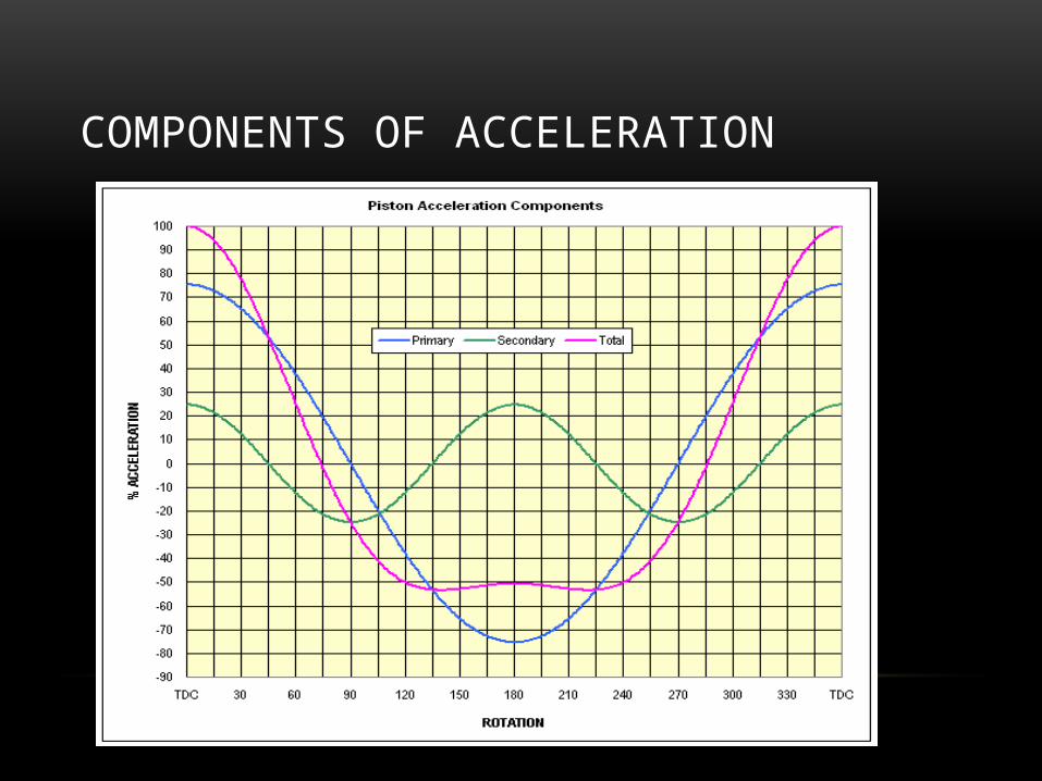
COMPONENTS OF ACCELERATION

FORCES IMPOSED ON A CRANKSHAFT• If the gas pressure is assumed to be 200bar and piston diameter of 10cm, the force on
crankshaft will be of the order of 16,000kgf.
• This level of force produces substantial bending and torsional moments and the resulting tensile, compressive and shear stresses.
• The combined weight of the piston, ring package, wristpin, retainers, small end of connecting rod and a small amount of oil are continuously accelerated from rest to very high velocity and back to rest twice each crankshaft revolution.
• Combustion forces and piston acceleration are also the main source of external vibration produced by an engine.
• Rotating mass associated with each crankpin, weight of the big end of connecting rod , connecting rod bearing(s), some amount of oil, and the mass of the crankshaft structure comprising the crankpin and cheeks.
• These rotating forces are counteracted by counterweight masses located in appropriate angular locations opposing the rod journals


TORSIONAL VIBRATION AND MATERIALS USED IN CRANKSHAFT MANUFACTURING
By- Shashi Ranjan 2010JE0772
TORSIONAL VIBRATIONS• Crankshaft has its own torsional resonant frequency as it has mass and its own torsional
stiffness
• Torsional resonant frequency of the crankshaft system is a function of:
• Crankshaft length
• Crankshaft torsional stiffness
• Crankshaft stroke
• Balance masses
• Moments of inertia of rotating items attached to or driven by the engine
• Crankshaft has very little inherent damping as it is made of lump of high-strength steel. Therefore, vibration attenuating device is provided at the free end of engine crankshaft.

CRANKSHAFT TORSIONAL ABSORBERS• Difference between damper and absorber
• Damper dissipates energy, mainly in the form of heat
• Absorber is a device which is designed to oscillate in direct opposition to a vibration at either a specific frequency or a specific order, depending on the design.
• Types of absorber
• Elastomer absorber
• Pendulum absorber
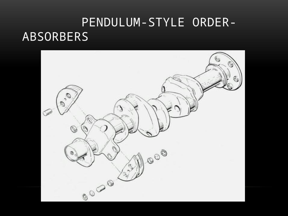
PENDULUM-STYLE ORDER-ABSORBERS
MATERIALS USED IN MANUFACTURE OF CRANKSHAFTS• Crankshaft are subjected to shock and fatigue loads. Therefore material should be tough
and fatigue resistant.
• The crankshafts are generally made of carbon steel, special steel or special cast iron.
• Medium-carbon steel alloys are composed of predominantly the element iron, and contain a small percentage of carbon (0.25% to 0.45%)
• Several alloying mix are carefully mixed carefully in order to produce specific qualities in target alloy.
• These qualities are hardenability, nitridability, surface and core hardness, ultimate tensile strength, yield strength, endurance limit (fatigue strength), ductility, impact resistance, and corrosion resistance.
• Alloying elements typically used are manganese, chromium, molybdenum, nickel, silicon, cobalt, vanadium, and sometimes aluminium and titanium.
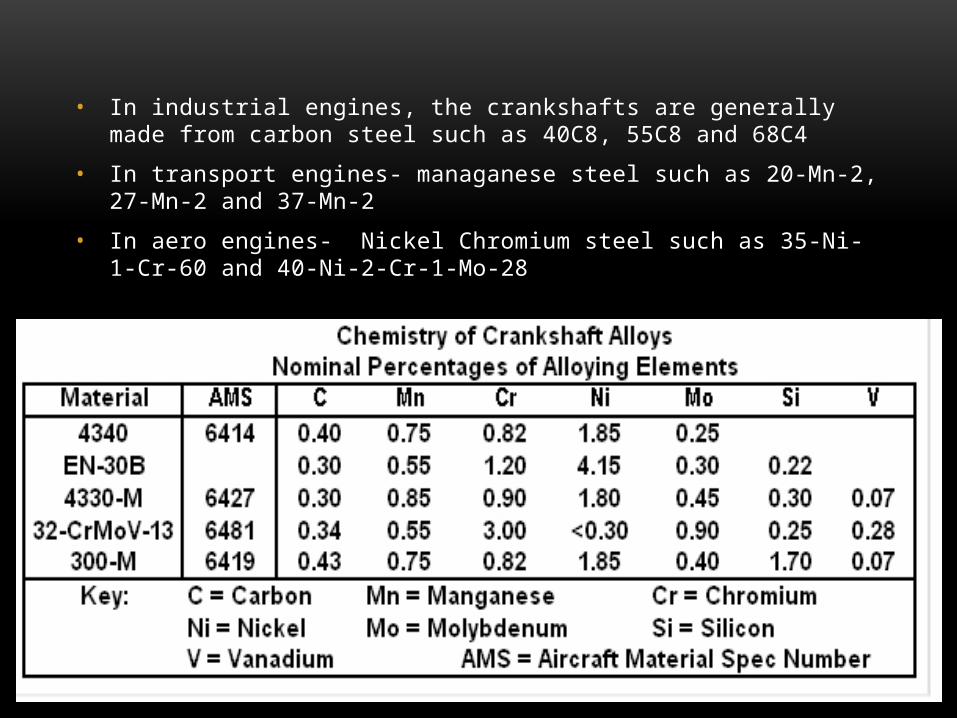
• In industrial engines, the crankshafts are generally made from carbon steel such as 40C8, 55C8 and 68C4
• In transport engines- managanese steel such as 20-Mn-2, 27-Mn-2 and 37-Mn-2
• In aero engines- Nickel Chromium steel such as 35-Ni-1-Cr-60 and 40-Ni-2-Cr-1-Mo-28
MANUFACTURING OF CRANK SHAFT
By: Sachin kumar 2010JE0751

MANUFACTURING OPERATIONS• Forging
• Crank web milling, Journal milling, Crank pin milling
• Drilling of flywheel flange, Drilling of crankpin, Drilling of crossed oil hole
• Grinding
• Crack Detection
• Nitriding
• Dynamic Balancing
• Lapping and Super finish
• Journal Grading and Bearing Selection

Raw forging
Billet Crankshaft machining

Drilling of crankpin Drilling of flywheel flange Drilling of crossed oil hole
Milling cutter used for journal and crankpin milling

• Grinding- Surface grinding is done for main journal and crank pin. Grinding of sidewalls is a critical step
• Crack detection- For a forged material there is possibility of internal flaws. Hence before sending materials for further operations, cracks are detected by magnaflux method.
• Nitriding- Higher surface hardness is obtained, extremely resistant to abrasion and high fatigue strength
• Lapping and Superfinishing- Crankshaft is super-finished so as to avoid cyclic fatigue failure
• Journal Grading and bearing selection

Fully counterweighted V8 crank
Bolt on counterweights

Thank you
Related Documents