Prescription Mode DDI Supporting Use Cases Joe W. Tevis

Welcome message from author
This document is posted to help you gain knowledge. Please leave a comment to let me know what you think about it! Share it to your friends and learn new things together.
Transcript
Prescription Mode DDISupporting Use Cases
Joe W. Tevis

TC Prescription Mode
DD Identifier ? TC Prescription Mode
Definition Defines the source of the TC setpoint value was obtained
Units
Range
Resolution
SAE SPN
Comments Idea is to define where the actual setpoint used was obtained from. 1 = Prescription Rate 2 = Prescription Default 3 = Prescription GPS loss 4 = Prescription Out Of Field 5 = Manual Entry 6 = Peer ControlGiven certain situations there are a given set of valid transitions between these modes. Control assignment may allow us to remove some of these items and change our proposal here.
Device Class(es)

CF SetPointMode
DD Identifier ? CF Setpoint Mode
Definition Defines the source of setpoint used by the control function (CF)
Units
Range
Resolution
SAE SPN
Comments Idea is to define where the actual setpoint used was obtained from. 1 = TC rate 2 = Manual Entry 3 = Peer Control 4 = Max override 5 = Min overrideGiven certain situations there are a given set of valid transitions between these modes. Control assignment may allow us to remove some of these items and change our proposal here.
Device Class(es)

Use Case Conditions
• Liquid Application Control System– Setpoint Mass per Area Application Rate , DDI=1– Actual Mass per Area Application Rate , DDI=2
• Relevant Task Attributes– PDV(DefaultTreatmentZone) = – PDV(PositionLostTreatmentZone) = 150– PDV(OutOfFieldTreatmentZone) =

Current Standard – Use Case 0
TC
Use Case Description: The system is operating optimally : Valid GPS, within the defined field boundary, and mass/time rate within machine capabilities.
Prescription MapValue = 200
CF
SetpointValue = 200
Control System
TASKDATA.XMLTASKDATA.XML
Actual Rate (as-applied)DDI = 2Value = 200 ±
SetpointValue = 200

Current Standard – Use Case 0
TC
Use Case Description: The system is operating optimally : Valid GPS, within the defined field boundary, and mass/time rate within machine capabilities.
Prescription MapValue = 200
CF
SetpointValue = 200
Control System
TASKDATA.XMLTASKDATA.XML
Actual Rate (as-applied)DDI = Value = 200 ±
SetpointValue = 200
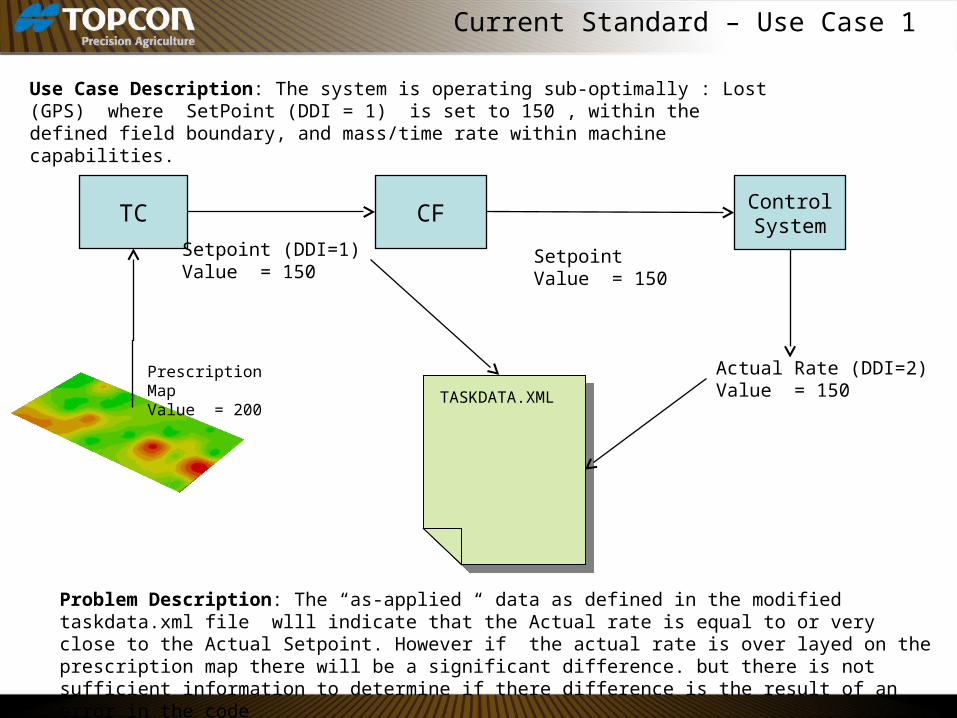
Current Standard – Use Case 1
TC
Use Case Description: The system is operating sub-optimally : Lost (GPS) where SetPoint (DDI = 1) is set to 150 , within the defined field boundary, and mass/time rate within machine capabilities.
Prescription MapValue = 200
CF
Setpoint (DDI=1)Value = 150
Control System
TASKDATA.XMLTASKDATA.XML
Actual Rate (DDI=2)Value = 150
Problem Description: The “as-applied “ data as defined in the modified taskdata.xml file wlll indicate that the Actual rate is equal to or very close to the Actual Setpoint. However if the actual rate is over layed on the prescription map there will be a significant difference. but there is not sufficient information to determine if there difference is the result of an error in the code
SetpointValue = 150

Current Standard – Use Case 2
TC
Use Case Description: The system is operating sub-optimally : Valid GPS, within the defined field boundary but the vehicle travel speed requires a mass/time above the applicator machine limit. Therefore the FC resets the Actual Setpoint to 175
Prescription MapValue = 200
CF
Actual SetpointValue = 200
Control System
TASKDATA.XMLTASKDATA.XML
Actual Rate (as-applied)DDI = 2Value = 175± 2
Problem Description: The “as-applied “ data as defined in the modified taskdata.xml file wll indicate that the Actual rate is equal to or very close to the Actual Setpoint. However if the actual rate is over layed on the prescription map there will be a significant difference. but there is not sufficient information to determine if there difference is the result of a “bug” in the code or if operating as designed
Actual SetpointValue = 175

Proposed Standard - Use Case 0
TC
Use Case Description: The system is operating optimally: valid GPS location, within the defined field boundary, and mass/time rate within machine capabilities.
Prescription Map Value = 200
CF
Actual SetpointValue = 200
Control System
Commanded SetpointValue = 200
TASKDATA.XMLTASKDATA.XML
Actual Rate (as-applied)DDI = Value = 200
CF SetPoint ModeValue = 1
TC Prescription ModeValue = 1

Proposed Standard - Use Case 1
TC
Use Case Description: The system is operating sub-optimally: lost position, within the defined field boundary, and mass/time rate within machine capabilities.
Prescription Map Value = 200
CF
Actual SetpointValue = 200
Control System
Commanded SetpointValue = 200
TASKDATA.XMLTASKDATA.XML
Actual Rate (as-applied)DDI = Value = 200
CF SetPoint ModeValue = 1
TC Prescription ModeValue = 3

Proposed Standard - Use Case 2
TC
Use Case Description: The system is operating sub-optimally: valid GPS location, within the defined field boundary, but required mass/time rate exceeds machine capabilities.
Prescription Map Value = 200
CF
Actual SetpointValue = 200
Control System
Commanded SetpointValue = 150
TASKDATA.XMLTASKDATA.XML
Actual Rate (as-applied)DDI = Value = 150
CF SetPoint ModeValue = 4
TC Prescription ModeValue = 1
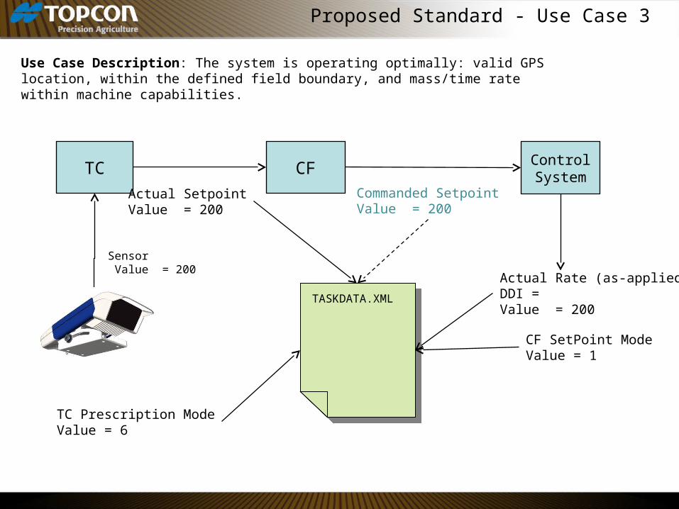
Proposed Standard - Use Case 3
TC
Use Case Description: The system is operating optimally: valid GPS location, within the defined field boundary, and mass/time rate within machine capabilities.
Sensor Value = 200
CF
Actual SetpointValue = 200
Control System
Commanded SetpointValue = 200
TASKDATA.XMLTASKDATA.XML
Actual Rate (as-applied)DDI = Value = 200
CF SetPoint ModeValue = 1
TC Prescription ModeValue = 6

Discussion/Questions
• How are multiple TC Prescription Modes supported?– Product “a” controlled by sensor (Peer)– Product “b” controlled by a map
• Multple TC?• How is the CF SetPoint Mode associated with a
specific CF?• A bit off topic: I would like to implement a “use last
rate” as an option to using preset values for both lost position and out-of-field.
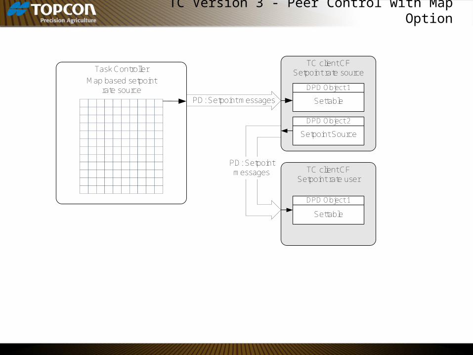
TC Version 3 - Peer Control with Map Option
Task ControllerTC client CF
Setpoint rate source
DPD Object 1
TC client CFSetpoint rate user
Map based setpoint rate source
Settable
DPD Object 2
Setpoint Source
DPD Object 1
Settable
PD: Setpoint messages
PD: Setpoint messages
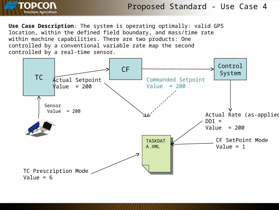
Proposed Standard - Use Case 4
TC
Use Case Description: The system is operating optimally: valid GPS location, within the defined field boundary, and mass/time rate within machine capabilities. There are two products: One controlled by a conventional variable rate map the second controlled by a real-time sensor.
Sensor Value = 200
CF
Actual SetpointValue = 200
Control System
Commanded SetpointValue = 200
TASKDATA.XML
TASKDATA.XML
Actual Rate (as-applied)DDI = Value = 200
CF SetPoint ModeValue = 1
TC Prescription ModeValue = 6

Down Force Margin
• Minimum Down Force: Minimum load cell reading over an 8 sec. period• Maximum Down Force: Maximum load cell reading over an 8 sec. period• Down Force: Down force averaged over an 8 sec. period as measure by a load
cell located between the main planter unit frame and the depth wheel linkage.• The diaphragm pressure is changed as the seed bin empties
• Minimum Required Down Force: Minimum down force required to maintain 100% contact between the soil and the depth wheel as determined by 20/20 research.
• Is this configurable by the user?• Does not account for variations in moisture content….this is managed by
the user by varying the diaphragm pressure and monitoring the down force margin
• The assumption is that if the down force is >= minimum down force the desired seed depth is maintained.
• Down Force Margin: (Down Force) – (Minimum Required Down Force)

Thank You
Related Documents