i Project No. 20-07 / Task 395 TTI Project 607141 MASH EQUIVALENCY OF NCHRP Report 350-APPROVED BRIDGE RAILINGS FINAL REPORT Prepared for: National Cooperative Research Program Transportation Research Board National Research Council Prepared by: Chiara Silvestri-Dobrovolny, Ph.D. Nathan Schulz Sana Moran Tyler Skinner Roger Bligh, Ph.D., P.E. William Williams, P.E. Texas A&M Transportation Institute 3135 TAMU College Station, Texas 77843-3135 November 2017 The information contained in this report was prepared as part of NCHRP Project 20-7, Task 395, National Cooperative Highway Research Program. SPECIAL NOTE: This report IS NOT an official publication of the National Cooperative Highway Research Program, Transportation Research Board, National Research Council, or The National Academies.

Welcome message from author
This document is posted to help you gain knowledge. Please leave a comment to let me know what you think about it! Share it to your friends and learn new things together.
Transcript

i
Project No. 20-07 / Task 395 TTI Project 607141
MASH EQUIVALENCY OF NCHRP Report 350-APPROVED BRIDGE RAILINGS
FINAL REPORT
Prepared for: National Cooperative Research Program
Transportation Research Board National Research Council
Prepared by:
Chiara Silvestri-Dobrovolny, Ph.D.
Nathan Schulz Sana Moran
Tyler Skinner Roger Bligh, Ph.D., P.E. William Williams, P.E.
Texas A&M Transportation Institute
3135 TAMU College Station, Texas 77843-3135
November 2017
The information contained in this report was prepared as part of NCHRP Project 20-7, Task 395, National Cooperative Highway Research Program.
SPECIAL NOTE: This report IS NOT an official publication of the National Cooperative Highway
Research Program, Transportation Research Board, National Research Council, or The National Academies.

ii
ACKNOWLEDGEMENTS This study was conducted for the National Cooperative Highway Research Program (NCHRP), Transportation Research Board, National Research Council with funding provided through NCHRP Project 20-7, Task 395, MASH Equivalency of NCHRP Report 350-Approved Bridge Railings. The NCHRP is supported by annual voluntary contributions from the state Departments of Transportation. Project 20-7 is intended to fund quick response studies on behalf of [appropriate committee]. The report was prepared by the Texas A&M Transportation Institute, Texas A&M University System. The work was guided by a technical working group. The project was managed by Waseem Dekelbab, PhD, PE, PMP, NCHRP Senior Program Officer.
The research team would like to thank the NCHRP Project 20-7 Task 395 Panel. The researchers are also grateful to all those that shared and contributed information toward the successful completion of this study, including State Departments of Transportation (DOTs), the Federal Highway Administration (FHWA) Office of Safety, the Office of Federal Lands Highway (FHL), and the Midwest Roadside Safety Facility (MwRSF). The collaboration on MASH implementation coordination provided the Roadside Safety Pooled Fund is also acknowledged and appreciated.
DISCLAIMER
The opinions and conclusions expressed or implied are those of the research agency that performed the research and are not necessarily those of the Transportation Research Board or its sponsoring agencies. This report has not been reviewed or accepted by the Transportation Research Board Executive Committee or the Governing Board of the National Research Council.

iii
ABSTRACT
National Cooperative Highway Research Program (NCHRP) Report 350 “Recommended Procedures for the Safety Performance Evaluation of Highway Features” was superseded by the American Association of State Highway and Transportation Officials (AASHTO) Manual for Assessing Safety Hardware (MASH) in 2009. MASH contained revised criteria for safety-performance evaluation of virtually all roadside safety features. Changes included new design vehicles and impact conditions that place greater safety-performance demands on many types of roadside safety hardware, including bridge rails.
A second edition of MASH was published in 2016. A MASH implementation agreement was jointly adopted by AASHTO and the Federal Highway Administration (FHWA) as part of the update process. The implementation agreement establishes dates for implementing MASH compliant safety hardware for new installations and full replacements on the National Highway System (NHS). The implementation date for bridge rails is December 31, 2019.
There are many types of non-proprietary bridge rails in use throughout the states. Under this project, research was performed to determine which bridge rails need to be retested to MASH criteria and which, if any, could be "grandfathered" based on equivalency between MASH and NCHRP Report 350 test levels. The research approach included identifying, categorizing, and prioritizing bridge rail systems, determining MASH equivalent test levels for different categories of bridge rails tested under previous criteria, performing detailed analysis of selected bridge rail systems, and developing justification for systems considered to be MASH compliant without further testing.

iv
TABLE OF CONTENTS Page
ACKNOWLEDGEMENTS ....................................................................................................... ii
ABSTRACT .............................................................................................................................. iii
TABLE OF CONTENTS .......................................................................................................... iv
LIST OF FIGURES ................................................................................................................. viii
LIST OF TABLES .................................................................................................................. xiv
EXECUTIVE SUMMARY .................................................................................................... xvii
1 BACKGROUND AND OBJECTIVE .................................................................................. 1
1.1 Introduction ................................................................................................................ 1 1.2 Research Objective .................................................................................................... 1 1.3 General Discussions ................................................................................................... 2
1.3.1 MASH Implementation Plan ................................................................................. 2 1.3.2 MASH Major Changes and Implications .............................................................. 2
2 IDENTIFICATION AND PRIORITIZATION OF BRIDGE RAIL SYSTEMS ................ 5
2.1 Survey Structure ......................................................................................................... 5 2.2 Survey Result Summaries by Bridge Rail System Category ................................... 10
2.2.1 Concrete Bridge Rail Systems ............................................................................. 10 2.2.2 Metal-Only Bridge Rail Systems ......................................................................... 19 2.2.3 Concrete-Metal Combined (Traffic-Only) Bridge Rail Systems ........................ 20 2.2.4 Combination Traffic-Pedestrian Bridge Rail Systems ........................................ 27 2.2.5 Wood Bridge Rail Systems ................................................................................. 29 2.2.6 Noise-Wall Bridge Rail Systems ......................................................................... 29 2.2.7 Retrofit Bridge Rail Systems ............................................................................... 29
2.3 Conclusions .............................................................................................................. 30
3 METHODOLOGY FOR EVALUATING TEST LEVEL EQUIVALENCY ................... 37
3.1 Test Level 2 (TL-2) and Test Level 3 (TL-3) Bridge Rail Systems ........................ 37 3.1.1 Stability Requirements ........................................................................................ 37 3.1.2 Strength Requirements ........................................................................................ 46 3.1.3 Geometric Requirements ..................................................................................... 50 3.1.4 Geometric Requirements for Specific Bridge Rail Categories ............................ 59
3.2 Test Level 4 (TL-4) Bridge Rail Systems ................................................................ 76 3.2.1 Stability Requirements ........................................................................................ 76

v
3.2.2 Strength Requirements ........................................................................................ 77 3.2.3 Geometric Requirements ..................................................................................... 78
3.3 Test Level 5 (TL-5) Bridge Rail Systems ................................................................ 79 3.3.1 Stability Requirements ........................................................................................ 79 3.3.2 Strength Requirements ........................................................................................ 79 3.3.3 Geometric Requirements ..................................................................................... 81
3.4 Summary of Test Levels 3, 4, and 5 Evaluation Requirements ............................... 81 3.5 Global Equivalency Results ..................................................................................... 83
4 RAIL SPECIFIC ANALYSIS METHODOLOGY ............................................................ 85
4.1 Stability Requirements for MASH Bridge Rail Systems ......................................... 85 4.2 Geometric Requirements for MASH Bridge Rail Systems ..................................... 86 4.3 Strength Requirements for MASH Bridge Rail Systems ......................................... 87 4.4 Rail Specific Analysis Methodology ....................................................................... 88
4.4.1 Solid Concrete Parapet Bridge Rail Systems ...................................................... 90 4.4.2 Concrete Post and Beam Bridge Rail Systems .................................................... 92 4.4.3 Steel Post and Beam Bridge Rail Systems .......................................................... 93 4.4.4 Combination Steel Post and Beam and Concrete Parapet Bridge Rail Systems . 94
4.5 Rail Specific Evaluation Assessment Designations ................................................. 96 4.5.1 Not Satisfactory ................................................................................................... 97 4.5.2 Satisfactory .......................................................................................................... 98 4.5.3 Marginal ............................................................................................................ 100 4.5.4 Overall Assessment ........................................................................................... 102
4.6 Rail Specific Analyses ........................................................................................... 102 4.6.1 Aesthetic Parapet Tube B-25-J (Michigan) ....................................................... 102 4.6.2 Concrete Parapet with Structural Tubing (Tennessee) ...................................... 105 4.6.3 S-352 Series Steel Tubing Concrete Combination (Vermont) .......................... 107 4.6.4 Kansas Corral 32in Without Curb (Virginia) .................................................... 109 4.6.5 Open Concrete Rail (Nebraska) ......................................................................... 111 4.6.6 4-Bar Steel Traffic Bicycle Railing on Curb (Maine) ....................................... 113 4.6.7 Alaska Multi-State Bridge Rail (Alaska) .......................................................... 115 4.6.8 George Washington Memorial Parkway (Federal Lands) ................................. 117 4.6.9 S3-TL4 (Massachusetts) .................................................................................... 119 4.6.10 Side Mounted Metal Bridge Railing (New Mexico) ......................................... 121 4.6.11 T4 Steel Bridge Rail (New Hampshire) ............................................................ 123 4.6.12 Two Tube Railing – 36c (Wyoming) ................................................................ 125 4.6.13 Two Tube Railing – 36d (Wyoming) ................................................................ 127 4.6.14 Type A42 Metal Bridge Railing (New Mexico) ................................................ 129 4.6.15 32-inch F-Shape (West Virginia) ...................................................................... 131 4.6.16 36-inch Single Slope (Tennessee) ..................................................................... 133 4.6.17 TL-4 42-inch F-Shape (Florida) ........................................................................ 135 4.6.18 TL-5 42-inch F-Shape (Pennsylvania) .............................................................. 136 4.6.19 42-inch Single Slope (New Mexico) ................................................................. 138 4.6.20 45-inch F-Shape (Indiana) ................................................................................. 140 4.6.21 C221 Bridge Rail (Texas) .................................................................................. 142

vi
4.6.22 Concrete Baluster Thrie-Beam Retrofit (Washington) ...................................... 144 4.7 Rail Specific Evaluation Results ............................................................................ 147
5 MASH IMPLEMENTATION COORDINATION EFFORTS ........................................ 155
6 ELIGIBILITY LETTERS ................................................................................................ 165
7 SUMMARY AND CONCLUSIONS ............................................................................... 167
7.1 Overview ................................................................................................................ 167 7.2 Identification and Prioritization of Bridge Rail Systems ....................................... 167 7.3 MASH Test Level Equivalency ............................................................................. 167 7.4 Rail Specific Analyses ........................................................................................... 168 7.5 MASH Implementation Coordination Effort ......................................................... 168 7.6 Eligibility Letters ................................................................................................... 169
REFERENCES ....................................................................................................................... 171
APPENDIX A: Survey ........................................................................................................... 175
APPENDIX B: Rail Analysis Spreadsheets ........................................................................... 179
Appendix B.1: Aesthetic Parapet Tube B-25-J (Michigan) ................................................ 180 Appendix B.2: Concrete Parapet with Structural Tubing (Tennessee) ............................... 188 Appendix B.3: S-352 Series Steel Tubing Concrete Combination (Vermont) ................... 198 Appendix B.4: Kansas Corral 32in without curb (Virginia) ............................................... 209 Appendix B.5: Open Concrete Rail (Nebraska) .................................................................. 215 Appendix B.6: 4-Bar Steel Traffic Bicycle Railing on Curb (Maine) ................................ 220 Appendix B.7: Alaska Multi-State Bridge Rail (Alaska) .................................................... 227 Appendix B.8: George Washington Memorial Parkway (Federal Lands) .......................... 233 Appendix B.9: S3-TL4 (Massachusetts) ............................................................................. 239 Appendix B.10: Side Mounted Metal Bridge Railing (New Mexico) ................................ 245 Appendix B.11: T4 Steel Bridge Rail (New Hampshire) .................................................... 251 Appendix B.12: Two Tube 36c (Wyoming)........................................................................ 257 Appendix B.13: Two Tube Railing-36d (Wyoming) .......................................................... 262 Appendix B.14: Type A42 Metal Bridge Railing (New Mexico) ....................................... 267 Appendix B.15: 32-inch F-Shape (West Virginia) .............................................................. 273 Appendix B.16: 36-inch Single Slope (Tennessee) ............................................................. 277 Appendix B.17: TL-4 42-inch F-Shape (Florida)................................................................ 282 Appendix B.18: TL-5 42-inch F-Shape (Pennsylvania) ...................................................... 287 Appendix B.19: 42-inch Single Slope (New Mexico) ........................................................ 291 Appendix B.20: 45-inch F-Shape (Indiana) ........................................................................ 296 Appendix B.21: C221 Bridge Rail (Texas) ......................................................................... 300 Appendix B.22: Concrete Baluster Thrie-Beam Retrofit (Washington) ............................. 304
APPENDIX C: FHWA Open Letter ....................................................................................... 309

vii
APPENDIX D: FHWA Eligibility Letter Requests ............................................................... 311
Appendix D.1: Aesthetic Parapet Tube B-25-J ................................................................... 312 Appendix D.2: Alaska Multi-State Bridge Rail (Alaska) .................................................... 317 Appendix D.3: Concrete Parapet with Structural Tubing (Tennessee) ............................... 321 Appendix D.4: S-352 Series Steel Tubing Concrete Combination (Vermont) ................... 325 Appendix D.5: Side Mounted Metal Bridge Railing (New Mexico) .................................. 331 Appendix D.6: Type A42 Metal Bridge Railing (New Mexico) ......................................... 335 Appendix D.7: 32-inch F-Shape (West Virginia) ............................................................... 340 Appendix D.8: 36-inch Single Slope (Tennessee) .............................................................. 345 Appendix D.9: TL-4 42-inch F-Shape (Florida) ................................................................. 351 Appendix D.10: 42-inch Single Slope (New Mexico) ........................................................ 357 Appendix D.11: TL-5 42-inch F-Shape (Pennsylvania) ..................................................... 363 Appendix D.12: 45-inch F-Shape (Indiana) ........................................................................ 369

viii
LIST OF FIGURES Page
Figure 1.1 MASH Implementation Deadlines for Roadside Safety Devices. ............................ 2
Figure 2.1 Adopted Methodology for Calculation of Weighted Frequency of Use (WFofU). .. 7
Figure 2.2 Summary for Vertical Post-and-Beam Concrete Barriers – Survey Results. ......... 12
Figure 2.3 Summary for Vertical Concrete Barriers – Survey Results. ................................... 13
Figure 2.4 Summary for New Jersey Concrete Barriers – Survey Results. ............................. 14
Figure 2.5 Summary for Single Slope Concrete Barriers – Survey Results. ............................ 15
Figure 2.6 Summary for F-Shape Concrete Barriers – Survey Results. ................................... 16
Figure 2.7 Weighted Frequency of Use for Concrete Barriers According to Test Levels – Survey Results. ......................................................................................................................... 17
Figure 2.8 Concrete Barriers – Survey Results Summary ........................................................ 18
Figure 2.9 Weighted Frequency of Use for Metal-Only Barriers – Survey Results. ............... 21
Figure 2.10 Weighted Frequency of Use for Deck and Curb Mounted Metal-Only Barriers – Survey Results. ......................................................................................................................... 21
Figure 2.11 Weighted Frequency of Use for Metal-Only Barriers with Railing Members – Survey Results. ......................................................................................................................... 22
Figure 2.12 Weighted Frequency of Use for Traffic-Only Combined Barriers – Survey Results. ..................................................................................................................................... 23
Figure 2.13 Weighted Frequency of Use for Traffic-Only Combined Barriers with Railing Members – Survey Results. ...................................................................................................... 25
Figure 2.14 Weighted Frequency of Use for Combination Traffic-Pedestrian Barriers – Survey Results. ......................................................................................................................... 28
Figure 3.1 Sequential Photographs of FE Simulation and Full-Scale Crash Test. ................... 41
Figure 3.2 Comparison of Roll and Pitch Angle for Full-Scale Crash Test and FE Simulation. .................................................................................................................................................. 43
Figure 3.3 Sequential Photographs of FE Simulation with 27-inch Barrier Height. ................ 44

ix
Figure 3.4 Sequential Photographs of FE Simulation with 28-inch Barrier Height. ................ 45
Figure 3.5 Sequential Photographs of FE Simulation with 29-inch Barrier Height. ................ 46
Figure 3.6 Simulation Setup. .................................................................................................... 48
Figure 3.7 50 ms Average Lateral Force along Height of Barrier. ........................................... 49
Figure 3.8 AASHTO Figure A13.1.1-2 – Potential for Wheel, Bumper, or Hood Impact with Post. .......................................................................................................................................... 52
Figure 3.9 AASHTO Figure 13.1.1-3 – Post Setback Criteria. ................................................ 52
Figure 3.10 MASH and NCHRP Report 350 Small Car Test Data – Post Setback versus Ratio of Rail Contact Width to Height. .............................................................................................. 54
Figure 3.11 MASH and NCHRP Report 350 Small Car Test Data – Post Setback versus Vertical Clear Opening. ............................................................................................................ 55
Figure 3.12 MASH and NCHRP Report 350 Pickup Truck Test Data – Post Setback versus Ratio of Rail Contact Width to Height. .................................................................................... 56
Figure 3.13 MASH and NCHRP Report 350 Pickup Truck Test Data – Post Setback versus Vertical Clear Opening. ............................................................................................................ 57
Figure 3.14 MASH 2270P Suspension after MASH TL-3 Crash Test. ................................... 58
Figure 3.15 NCHRP Report 350 2000P Suspension after NCHRP Report 350 TL-3 Crash Test. .......................................................................................................................................... 58
Figure 3.16 MASH and NCHRP Report 350 Small Car Test Data – Post Setback versus Ratio of Rail Contact Width to Height. .............................................................................................. 62
Figure 3.17 MASH and NCHRP Report 350 Small Car Test Data – Post Setback Distance versus Vertical Clear Opening. ................................................................................................. 62
Figure 3.18 MASH and NCHRP Report 350 Pickup Truck Test Data – Post Setback versus Ratio of Rail Contact Width to Height. .................................................................................... 63
Figure 3.19 MASH and NCHRP Report 350 Pickup Truck Test Data – Post Setback versus Vertical Clear Opening. ............................................................................................................ 63
Figure 3.20 Comparison of Damage to NCHRP Report 350 3-10 Small Car for T202 Bridge Rail. .......................................................................................................................................... 64
Figure 3.21 TxDOT T224 and Nebraska Open Bridge Rail. ................................................... 65

x
Figure 3.22 MASH and NCHRP Report 350 Small Car Test Data – Post Setback versus Ratio of Rail Contact Width to Height. .............................................................................................. 66
Figure 3.23 MASH and NCHRP Report 350 Small Car Test Data – Post Setback versus Vertical Clear Opening. ............................................................................................................ 67
Figure 3.24 MASH and NCHRP Report 350 Pickup Truck Test Data – Post Setback versus Ratio of Rail Contact Width to Height. .................................................................................... 67
Figure 3.25 MASH and NCHRP Report 350 Pickup Truck Test Data – Post Setback versus Vertical Clear Opening. ............................................................................................................ 68
Figure 3.26 Damage to TxDOT T101 Bridge Rail. .................................................................. 68
Figure 3.27 Damage to TxDOT T131 Bridge Rail. .................................................................. 69
Figure 3.28 MASH and NCHRP Report 350 Small Car Test Data – Post Setback versus Ratio of Rail Contact Width to Height. .............................................................................................. 71
Figure 3.29 MASH and NCHRP Report 350 Small Car Test Data – Post Setback versus Vertical Clear Opening. ............................................................................................................ 71
Figure 3.30 MASH and NCHRP Report 350 Pickup Truck Test Data – Post Setback versus Ratio of Rail Contact Width to Height. .................................................................................... 72
Figure 3.31 MASH and NCHRP Report 350 Pickup Truck Test Data – Post Setback versus Vertical Clear Opening. ............................................................................................................ 72
Figure 3.32 Damage to Barrier and Vehicle for ST-10 Bridge Rail. ....................................... 73
Figure 3.33 MASH and NCHRP Report 350 Small Car Test Data – Post Setback versus Ratio of Rail Contact Width to Height. .............................................................................................. 74
Figure 3.34 MASH and NCHRP Report 350 Small Car Test Data – Post Setback versus Vertical Clear Opening. ............................................................................................................ 75
Figure 3.35 MASH and NCHRP Report 350 Pickup Truck Test Data – Post Setback versus Ratio of Rail Contact Width to Height. .................................................................................... 75
Figure 3.36 MASH and NCHRP Report 350 Pickup Truck Test Data – Post Setback versus Vertical Clear Opening. ............................................................................................................ 76
Figure 3.37 TxDOT T224 MASH TL-5 Bridge Rail System. ................................................. 80
Figure 4.1 AASHTO Section 13 Figures A13.1.1-2 and A13.1.1-3. ....................................... 87

xi
Figure 4.2 Stability Criteria Evaluation. ................................................................................... 89
Figure 4.3 AASHTO Section 13 Figures A13.1.1-2 and A13.1.1-3. ....................................... 90
Figure 4.4 Design Forces for Bridge Railings. ......................................................................... 90
Figure 4.5 Example of a Portion of the Solid Concrete Parapet Strength Analysis Segment of the Template. ............................................................................................................................ 92
Figure 4.6 Example of a Portion of the Concrete Post and Beam Strength Analysis Segment of the Template ............................................................................................................................. 93
Figure 4.7 Example of a Portion of the Steel Post and Beam Strength Analysis Segment of the Template. .................................................................................................................................. 94
Figure 4.8 Example of the Resultant Strength Portion of the Combination Steel Post and Concrete Parapet Segment of the Template. ............................................................................ 96
Figure 4.9 Example of Not Satisfactory Designation for Geometric Criteria. ......................... 97
Figure 4.10 Example of Not Satisfactory Designation for Geometric Criteria. ....................... 98
Figure 4.11 Example of Satisfactory Designation for Geometric Criteria. .............................. 99
Figure 4.12 Example of Satisfactory Designation for Geometric Criteria. ............................ 100
Figure 4.13 Example of Data Point Resulting in Marginal Designation. ............................... 101
Figure 4.14 Example of Data Point Resulting in Marginal Designation. ............................... 101
Figure 4.15 Detailed View of Aesthetic Parapet Tube B-25-J. .............................................. 103
Figure 4.16 Geometric Criteria Assessment of Aesthetic Parapet Tube B-25-J. ................... 104
Figure 4.17 Detailed View of Concrete Parapet with Structural Tubing. .............................. 105
Figure 4.18 Geometric Criteria Assessment of Concrete Parapet with Structural Tubing. ... 106
Figure 4.19 Detailed View of S-352 Series Steel Tubing Concrete Combination. ................ 107
Figure 4.20 Geometric Criteria Assessment of S-352 Series Steel Tubing Concrete Combination. .......................................................................................................................... 108
Figure 4.21 Detailed View of Kansas Corral 32in Without Curb. ......................................... 109
Figure 4.22 Geometric Criteria Assessment of Kansas Corral 32in Without Curb. .............. 110

xii
Figure 4.23 Detailed View of Open Concrete Bridge Rail. ................................................... 111
Figure 4.24 Geometric Criteria Assessment of Open Concrete Bridge Rail. ......................... 112
Figure 4.25 Detailed View of 4-Bar Steel Traffic Bicycle Railing on Curb. ......................... 114
Figure 4.26 Geometric Criteria Assessment of 4-Bar Steel Traffic Bicycle Railing on Curb. ................................................................................................................................................ 114
Figure 4.27 Detailed View of Alaska Multi-State Bridge Rail. ............................................. 116
Figure 4.28 Geometric Criteria Assessment of Alaska Multi-State Bridge Rail. .................. 117
Figure 4.29 Detailed View of George Washington Memorial Parkway. ............................... 118
Figure 4.30 Geometric Criteria Assessment of George Washington Memorial Parkway. .... 119
Figure 4.31 Detailed View of S3-TL4 Bridge Rail. ............................................................... 120
Figure 4.32 Geometric Criteria Assessment of S3-TL4 Bridge Rail. .................................... 121
Figure 4.33 Detailed View of Side Mounted Metal Bridge Railing. ...................................... 122
Figure 4.34 Geometric Criteria Assessment of Side Mounted Metal Bridge Railing. ........... 123
Figure 4.35 Detailed View of T4 Steel Bridge Rail. .............................................................. 124
Figure 4.36 Geometric Criteria Assessment of T4 Steel Bridge Rail. ................................... 125
Figure 4.37 Detailed View of Two Tube Railing – 36c. ........................................................ 126
Figure 4.38 Geometric Criteria Assessment of Two Tube Railing – 36c. ............................. 127
Figure 4.39 Detailed View of Two Tube Railing – 36d. ........................................................ 128
Figure 4.40 Geometric Criteria Assessment of Two Tube Railing – 36d. ............................. 129
Figure 4.41 Detailed View of Type A42 Metal Bridge Railing. ............................................ 130
Figure 4.42 Geometric Criteria Assessment of Type A42 Metal Bridge Railing. ................. 131
Figure 4.43 Detailed View of 32-inch F-Shape. ..................................................................... 132
Figure 4.44 Detailed View of 36-inch Single Slope. .............................................................. 134
Figure 4.45 Detailed View of TL-4 42-inch F-Shape. ........................................................... 135

xiii
Figure 4.46 Detailed View of TL-5 42-inch F-Shape. ........................................................... 137
Figure 4.47 Detailed View of 42-inch Single Slope. .............................................................. 139
Figure 4.48 Detailed View of 45-inch F-Shape. ..................................................................... 141
Figure 4.49 Detailed View of C221 Bridge Rail. ................................................................... 142
Figure 4.50 MASH Pickup Truck Vehicle Parts Contacting Above Vertical Barriers. ......... 143
Figure 4.51 Detailed View of Concrete Baluster Thrie-Beam Retrofit .................................. 146
Figure 4.52 Comparison of S-352 Series and BR-2-15 Bridge Rails. .................................... 153

xiv
LIST OF TABLES Page
Table 2.1 Summary of Survey Results Divided by Proposed Bridge Rail Categories. .............. 9
Table 2.2 Weighted Frequency of Use Comparison for Concrete Barriers – Survey Results. 19
Table 2.3 Weighted Frequency of Use for Metal-Only Barriers – Survey Results. ................. 20
Table 2.4 Weighted Frequency of Use for Traffic-Only Combined Barriers with Railing Members – Survey Results. ...................................................................................................... 26
Table 2.5 Weighted Frequency of Use for Combination Traffic-Pedestrian Barriers – Survey Results. ..................................................................................................................................... 29
Table 2.6 Ranking Based on Weighted Frequency of Use per Category – Survey Results. .... 31
Table 2.7 TL-2 Ranking Based on Weighted Frequency of Use – Survey Results. ................ 32
Table 2.8 TL-3 Ranking Based on Weighted Frequency of Use – Survey Results. ................ 33
Table 2.9 TL-4 Ranking Based on Weighted Frequency of Use – Survey Results. ................ 34
Table 2.10 TL-5 Ranking Based on Weighted Frequency of Use – Survey Results. .............. 35
Table 3.1 Impact Severity for Test 11. ..................................................................................... 47
Table 3.2 Impact Forces for Test 11. ........................................................................................ 50
Table 3.3 MASH Bridge Rail Systems and Geometry. ............................................................ 54
Table 3.4 Concrete Beam-and-Post Bridge Rail Systems and Geometry. ............................... 61
Table 3.5 Metal Beam-and-Post Deck Mounted Bridge Rail Systems and Geometry. ........... 66
Table 3.6 Metal Beam-and-Post Curb Mounted Bridge Rail Systems and Geometry. ............ 70
Table 3.7 Metal Rail on Concrete Parapet Bridge Rail Systems and Geometry. ..................... 74
Table 3.8 Impact Severity for MASH Test 4-12. ..................................................................... 77
Table 3.9 Summary of Magnitude, Distribution and Application of the MASH TL-4 Impact Loads. ....................................................................................................................................... 78
Table 3.10 Summary of Magnitudes, Distributions and Resultant Height of Loads for MASH TL-5 Impact. ............................................................................................................................. 80

xv
Table 3.11 Summary of Global Test Equivalency for NCHRP Report 350 Bridge Rail Systems. .................................................................................................................................... 83
Table 4.1 Minimum Height Requirements for MASH TL-3, TL-4, and TL-5. ....................... 86
Table 4.2 Design Impact Loads. ............................................................................................... 88
Table 4.3 Example of Not Satisfactory Designation for Stability Criteria. .............................. 97
Table 4.4 Example of Not Satisfactory Designation for Strength Criteria. .............................. 98
Table 4.5 Example of Satisfactory Designation for Stability Criteria. ..................................... 99
Table 4.6 Example of Satisfactory Designation for Strength Criteria. ................................... 100
Table 4.7 Example of Not Satisfactory Designation for Overall Assessment. ...................... 102
Table 4.8 Example of Satisfactory Designation for Overall Assessment.............................. 102
Table 4.9 Summary of Assessment of Aesthetic Parapet Tube B-25-J. ................................. 105
Table 4.10 Summary of Assessment of Concrete Parapet with Structural Tubing. ............... 107
Table 4.11 Summary of Assessment of S-352 Series Steel Tubing Concrete Combination. . 109
Table 4.12 Summary of Assessment of Kansas Corral 32in Without Curb. .......................... 111
Table 4.13 Summary of Assessment of Open Concrete Bridge Rail. .................................... 113
Table 4.14 Summary of Assessment of 4-Bar Steel Traffic Bicycle Railing on Curb. .......... 115
Table 4.15 Summary of Assessment of Alaska Multi-State Bridge Rail. .............................. 117
Table 4.16 Summary of Assessment of George Washington Memorial Parkway. ................ 119
Table 4.17 Summary of Assessment of S3-TL4 Bridge Rail. ................................................ 121
Table 4.18 Summary of Assessment of Side Mounted Metal Bridge Railing. ...................... 123
Table 4.19 Summary of Assessment of T4 Steel Bridge Rail. ............................................... 125
Table 4.20 Summary of Assessment of Two Tube Railing – 36c. ......................................... 127
Table 4.21 Summary of Assessment of Two Tube Railing – 36d. ......................................... 129
Table 4.22 Summary of Assessment of Type A42 Metal Bridge Railing. ............................. 131

xvi
Table 4.23 Summary of Assessment of 32-inch F-Shape. ..................................................... 133
Table 4.24 Summary of Assessment of 36-inch Single Slope. .............................................. 134
Table 4.25 Summary of Assessment of TL-4 42-inch F-Shape. ............................................ 136
Table 4.26 Summary of Assessment of TL-5 42-inch F-Shape. ............................................ 138
Table 4.27 Summary of Assessment of 42-inch Single Slope. .............................................. 140
Table 4.28 Summary of Assessment of 45-inch F-Shape. ..................................................... 141
Table 4.29 Summary of Assessment of C221 Bridge Rail. .................................................... 143
Table 4.30 Summary of Assessment of Concrete Baluster Thrie-Beam Retrofit. ................. 147
Table 4.31 Rail Specific Evaluation Results. ......................................................................... 148
Table 4.32 List of Similar or Less Critical Rails. ................................................................... 154
Table 5.1 Bridge Rail Systems Listed on MASH Database. .................................................. 156
Table 5.2 Planned Bridge Rail Systems Tests ........................................................................ 163
Table 7.1 Summary of Global Test Equivalency for NCHRP Report 350 Bridge Rail Systems. ................................................................................................................................................ 168

xvii
EXECUTIVE SUMMARY
National Cooperative Highway Research Program (NCHRP) Report 350 “Recommended Procedures for the Safety Performance Evaluation of Highway Features” was superseded by the American Association of State Highway and Transportation Officials (AASHTO) Manual for Assessing Safety Hardware (MASH) in 2009. MASH contains revised criteria for safety-performance evaluation of virtually all roadside safety features. Changes included new design vehicles and impact conditions that place greater safety-performance demands on many types of roadside safety hardware, including bridge rails.
A second edition of MASH was published in 2016. A MASH implementation agreement was jointly adopted by AASHTO and the Federal Highway Administration (FHWA) as part of the update process. The implementation agreement establishes dates for implementing MASH compliant safety hardware for new installations and full replacements on the National Highway System (NHS). The implementation date for bridge rails is December 31, 2019.
There are many types of non-proprietary bridge rails in use throughout the states. Under this project, research was performed to determine which bridge rails need to be retested to MASH criteria and which, if any, could be "grandfathered" based on equivalency between MASH and NCHRP Report 350 test levels. The research approach included identifying, categorizing, and prioritizing bridge rail systems, determining MASH equivalent test levels for different categories of bridge rails tested under previous criteria, performing detailed analysis of selected bridge rail systems, and developing justification for systems considered to be MASH compliant without further testing.
An electronic, web-based survey was used to obtain input from State Departments of Transportation (DOTs). The survey requested information regarding the type and frequency of use of non-proprietary domestic bridge rails in each state. A total of 34 survey responses were collected, including 33 DOT Agencies and FHWA Federal Lands. The submitted bridge rail systems were categorized by rail type and NCHRP Report 350 test level, and prioritized based on weighted frequency of use.
Analyses were performed to assist with a performance-based comparison of test levels
between NCHRP Report 350 and MASH. Three key criteria were considered during this evaluation process: vehicle stability, bridge rail strength, and bridge rail geometrics. Minimum rail heights were established for each test level through consideration of available full-scale crash test and finite element impact simulation data. These minimum rail heights are 29 inches, 36 inches, and 42 inches for Test Levels 3, 4, and 5, respectively. These rail heights were used to evaluate relative vehicle stability between the two test criteria. Structural adequacy criterion was evaluated through consideration of lateral design impact loads and their application heights. The lateral design impact load defines the required capacity of a bridge rail system for a given test level. Available test data was used to assess the relevance of existing empirical relationships related to potential for vehicle snagging interaction between structural elements of the vehicle and bridge rail system. Various geometric characteristics, such as post set back distance, vertical clear opening, and ratio of contact surface to rail height, were plotted for bridge rail systems tested to different test levels under

xviii
both NCHRP Report 350 and MASH criteria. The outcomes of these tests in relation to the recommended regions of the relationships were used to assess relevancy of the criteria to different MASH test levels.
NCHRP Report 350 TL-5 is considered equivalent to MASH TL-5. NCHRP Report
350 TL-3 and TL-4 are not globally equivalent, but some bridge rail categories were considered to have equivalency. Specifically, NCHRP Report 350 TL-3 and TL-4 solid concrete parapets and metal rails on concrete parapets with a parapet height greater than 24 inches are considered acceptable under MASH TL-3. NCHRP Report 350 TL-3 and TL-4 concrete post and beam, metal rail deck, or curb mounted systems can be found acceptable under MASH TL-2.
Since many of the NCHRP 350 bridge rail systems are not eligible to be grandfathered
under MASH, more detailed analyses and evaluation of specific rail systems was performed. The funding resources allocated for this project were not sufficient to perform a detailed strength analysis and impact performance evaluation of every bridge rail system identified. Therefore, the bridge rail systems with the highest priority were selected for individual analysis to assess compliance with MASH criteria. The analyses considered vehicle stability, structural adequacy, and bridge rail geometrics. For a bridge rail system to be considered a MASH acceptable barrier, a minimum height must be met to ensure stability of the vehicle.
Using procedures in Section 13 of the AASHTO LRFD Bridge Design Specifications,
an analysis of the strength of the rail system was performed. For concrete parapet railings, the yield line method was applied to determine the ultimate strength of the system. Metal rail systems were analyzed using plastic strength analysis methods. The strength of the rail members, posts, and post connections were analyzed to obtain the overall strength of the rail system. Limiting failure modes determined from previous NCHRP Report 350 crash tests of the rail system and/or similar rail systems were considered. The calculated strength of the bridge rail systems was compared to design impact loads corresponding to the relevant MASH Test Level to evaluate sufficiency of barrier capacity.
Rail geometrics and propensity for snagging were analyzed using relationships in
Figures A13.1.1-2 and A13.1.1-3 of the AASHTO LRFD Bridge Design Specifications. For each bridge rail system analyzed, post setback distance, ratio of contact width to height, and vertical clear opening were determined or calculated from the provided bridge rail details and plotted against the current geometric criteria. The bridge rail had to plot in the recommended regions to receive a Satisfactory assessment.
Out of the 22 bridge rail systems analyzed, 13 were given a Satisfactory overall
assessment. To receive an overall assessment of Satisfactory, a bridge rail system must receive a Satisfactory designation for each of the three evaluation criteria: stability, rail geometrics, and strength. Other bridge rail systems that were similar or less critical than the 13 systems with a Satisfactory overall assessment are also considered Satisfactory. This resulted in a total of 50 bridge rail systems found to be MASH compliant.

xix
The bridge rail systems that were given a Not Satisfactory overall assessment had a Marginal or Not Satisfactory designation for at least one of the three criteria. Note that a Not Satisfactory overall assessment does not mean that the investigated bridge rail system will not meet MASH criteria. Rather, it means that a determination regarding MASH compliance cannot be confidently made and further testing in accordance with MASH criteria is recommended.
Eligibility request forms were developed for each of the analyzed bridge rail systems that received a Satisfactory overall designation. An open letter dated May 26, 2017 states that FHWA will no longer accept and review any eligibility requests based solely or in part on engineering analysis. Thus, the eligibility requests developed under this project will not be considered by FHWA. However, the eligibility justification can still be reviewed and considered by individual State DOTs.
Throughout the project, researchers coordinated with research facilities, pooled fund
programs, testing laboratories and user agencies to collect and share information regarding completed or planned MASH bridge rail crash tests. Collected data has been incorporated into a database that is available on the Roadside Safety Pooled Fund site under the MASH implementation page (https://www.roadsidepooledfund.org/mash-implementation/search/). The database contains information on MASH tested bridge rail systems as well as other categories of roadside safety hardware. At the writing of this report, the MASH database contained a total of 33 entries under the “Bridge Rail” category. These systems are summarized in the report. MASH implementation testing plans were also collected. Twenty-two bridge rail systems ranging from TL-2 to TL-5 are currently programmed for full-scale crash testing by various state DOTs at the writing of this report. These systems are summarized in the report.

1
1 BACKGROUND AND OBJECTIVE 1.1 Introduction National Cooperative Highway Research Program (NCHRP) Report 350 “Recommended Procedures for the Safety Performance Evaluation of Highway Features” contains guidelines for evaluating the safety performance of roadside features, such as longitudinal barriers, terminals, crash cushions, and breakaway structures.(1) This document was published in 1993 and was formally adopted as the national standard by the Federal Highway Administration (FHWA) later that year with an implementation date for late 1998. An update to NCHRP Report 350 was developed under NCHRP Project 22-14(02), “Improvement of Procedures for the Safety-Performance Evaluation of Roadside Features.” The resulting document was published by the American Association of State Highway Transportation Officials (AASHTO) as the Manual for Assessing Safety Hardware (MASH). MASH contains revised criteria for safety-performance evaluation of virtually all roadside safety features.(2) For example, MASH recommends testing with heavier light truck vehicles to better represent the current fleet of vehicles in the pickup/van/sport-utility vehicle class. Further, MASH increases the impact angle for most small car crash tests to the same angle as the light truck test conditions. These changes place greater safety-performance demands on many current roadside safety features. AASHTO recently published the second edition of MASH in December 2016. (3) As part of this process, the Federal Highway Administration (FHWA) and AASHTO adopted a joint implementation agreement that establishes dates for implementing MASH compliant safety hardware for new installations and full replacements on the National Highway System (NHS). Although some barrier testing was performed during the development of the updated criteria, many barrier systems and other roadside safety features have yet to be evaluated under MASH criteria. Therefore, evaluation of the remaining widely used roadside safety features using the safety-performance evaluation guidelines included in MASH is needed. There are many types of non-proprietary bridge rails in use throughout the states, and research is needed to determine which rail systems need to be retested to MASH criteria and which, if any, can be "grandfathered" based on evaluation under previous criteria. In 1997, FHWA provided a list of 74 bridge rails and their equivalent NCHRP Report 350 test levels based on testing performed under the earlier NCHRP Report 230 test levels and the performance levels contained in the AASHTO Guide Specification for Bridge Rails.(4) In 2000, FHWA provided guidance that allowed for demonstrating that variations of an accepted bridge rail design would not have to be crash tested if the basic geometry of the bridge rail has not been changed and the structural design of the rail is comparable to the rail that has been tested.(5) 1.2 Research Objective The objectives of this project are to identify and prioritize bridge railings, determine equivalent test levels between NCHRP Report 350 and MASH, and determine whether

2
individual types of bridge railing can be considered MASH compliant or if retesting is needed. 1.3 General Discussions 1.3.1 MASH Implementation Plan MASH is the latest in a series of documents that provides guidance on testing and evaluation of roadside safety features.(2) MASH was published in 2009 and represents a comprehensive update to crash test and evaluation procedures to reflect changes in the vehicle fleet, operating conditions, and roadside safety knowledge and technology. It supersedes National Cooperative Highway Research Program (NCHRP) Report 350, ‟Recommended Procedures for the Safety Performance Evaluation of Highway Features.”(1) A second edition of MASH was published in 2016.(3) AASHTO and FHWA adopted a MASH implementation plan that has compliance dates for installing MASH hardware that differ by hardware category. The different dates and associated roadside safety hardware categories are shown in Figure 1.1. According to the plan, all new installations of roadside safety devices on the NHS on projects let after December 31, 2019 must be MASH compliant. The FHWA no longer issues eligibility letters for highway safety hardware under previous performance criteria.
Figure 1.1 MASH Implementation Deadlines for Roadside Safety Devices.
1.3.2 MASH Major Changes and Implications MASH incorporated significant changes and additions to the procedures for the safety performance of roadside safety hardware, including new design vehicles that better reflect the changing character of vehicles using the highway network. For example, MASH increased the weight of the pickup truck design test vehicle from 4,409 lb to 5,000 lb, changed the body style from a ¾-ton, standard cab to a ½-ton, 4-door, and imposes a minimum height for the vertical center of gravity (CG) of 28 inches. The increase in vehicle mass represents an increase in impact severity of approximately 13 percent with respect to the impact conditions of NCHRP Report 350. The increased impact severity may result in increased impact forces and larger lateral barrier deflections compared to NCHRP Report 350 impact conditions.

3
The impact conditions for the small car test have also changed. The weight of the small passenger design test vehicle increased from 1,800 lb to 2,420 lb, and the impact angle increased from 20 degrees to 25 degrees. These changes represent an increase in impact severity of 206 percent for Test 3-10 with the small car design test vehicle with respect to the impact conditions of NCHRP Report 350. This increase in impact severity may result in increased vehicle snagging and occupant compartment deformation, and could possibly aggravate vehicle stability during impacts with certain types of barriers. Similar to NCHRP Report 350, MASH defines six test levels for longitudinal barriers. Each test level places an increasing level of demand on the structural capacity of a barrier system. At a minimum, all barriers on high-speed roadways on the National Highway System (NHS) are required to meet Test Level 3 (TL-3) requirements. The structural adequacy test for this test level consists of a 5,000-lb pickup truck (denoted 2270P) impacting the barrier at a speed of 62 mph and an angle of 25 degrees. The severity test consists of a 2,420-lb passenger car (denoted 1100C) impacting the barrier at the same speed and angle. Most state departments of transportation require that their bridge railings and median barriers meet Test Level 4 (TL-4), which includes a test with a 24,240-lb single unit truck (denoted 10000S) impacting the barrier at a speed of 56 mph and an angle of 15 degrees. Higher containment barriers are sometimes used when conditions such as a high percentage of truck traffic or the nature of a hazard underlying a bridge so warrant. Higher test levels (e.g., TL-5 and TL-6) include evaluation with 80,000-lb tractor-van trailers and tractor-tank trailers. Such barriers are necessarily taller, stronger, heavier, and more expensive to construct. Under TxDOT Research Project 9-1002 ‟Roadside Safety Device Crash Testing Program,” TTI researchers investigated the minimum height and lateral design load for MASH TL-4 bridge rails.(6) Under MASH, the severity of TL-4 impacts increased 56% compared to NCHRP Report 350. Consequently, 32 inch tall barriers that met TL-4 requirements under NCHRP Report 350 do not satisfy MASH. The minimum rail height for MASH TL-4 barriers was determined to be 36 inches. The lateral design impact load was found to vary with rail height. For a 36-inch tall barrier (the minimum height required to meet stability requirements for the single unit truck), the design impact load is 68 kips. As the height of the barrier increases, more of the cargo box of the single unit truck is engaged and the lateral load on the barrier increases. For a barrier height of 42 inches, the lateral design impact load for TL-4 is 80 kips.(6)


5
2 IDENTIFICATION AND PRIORITIZATION OF BRIDGE RAIL SYSTEMS
2.1 Survey Structure The research team prepared and distributed an electronic survey seeking input from State Departments of Transportation (DOTs). The survey requested information regarding the type and frequency of use of non-proprietary domestic bridge rails in each state. Additionally, for each of their bridge rail systems, the DOT was asked whether they intend to discontinue its use or pursue MASH eligibility. The information was collected through a web-based survey instrument. Follow up telephone and email communications were made to resolve questions, clarify information, or request additional input. The web based survey was e-mailed to appropriate contact persons in each state. AASHTO assisted the research team with identification of appropriate contact persons and information. The research team additionally reached out to active State DOT members of the Roadside Safety Pooled Fund, Midwest States Pooled Fund, AASHTO Technical Committee for Roadside Safety, and AASHTO Subcommittee on Bridges and Structures, Technical Committee T-7 “Guardrail and Bridge Rail.”
In addition to verifying the types of bridge rails currently in use, the survey also requested relative frequency of use for each rail type. Because actual inventory data of bridge rails is not typically available, this was accomplished using the following categories: Never; Rarely (1-25%); Somewhat Frequently (26-50%); Frequently (51-75%); and Very Frequently (76-100%). The respondent was asked to indicate their state’s frequency of use of each type of bridge rail using these percentages based on best available knowledge. In addition, two additional check boxes were presented to indicate whether or not the state plans to discontinue use of the bridge rail system or pursue MASH eligibility to permit its continued use on the NHS beyond the implementation date. Finally, the respondent was asked to provide standard details for each of their bridge rail systems. A copy of the submitted electronic survey instrument is provided in Appendix A.
The research team analyzed the information and determined those bridge rails which are most frequently used and would, therefore, be high priority for evaluation to MASH criteria. The bridge rails in each category were ranked by the researchers in order of weighted frequency of use.
A total of 34 survey responses were collected, including 33 DOT Agencies and FHWA Federal Lands. The research team reviewed and organized the survey responses based on the following bridge rail categories and sub-categories:
• Concrete Only
o Vertical profile o Vertical profile, post and beams o New Jersey profile o Single Slope profile o F-Shape profile

6
• Metal Only o Deck-Mounted o Side-Mounted
• Concrete-Metal Combined (Traffic Only) o With Curb
3 metal members 2 metal members 1 metal member
o With Parapet 3 metal members 2 metal members 1 metal member
• Combination Traffic-Pedestrian o With Sidewalk o Without Sidewalk
• Wood Only • Noise Wall Only • Retrofit Only
For each sub-category, the research team grouped the received bridge rail systems by
test level, and developed a Weighted Frequency of Use (WFofU) based on the relative frequency of use indicated for each rail type. As shown below, each rail system was assigned a weighted value based on the reported frequency of use from a DOT. The number represents the Weighed Frequency of Use of a DOT for that specific bridge rail system at the considered Test Level:
• Never (up to 1%) 1 • Rarely (1-25%) 2 • Somewhat Frequently (26-50%) 3 • Frequently (51-75%) 4 • Very Frequently (76-100%) 5
The WFofU for a given bridge rail system for a specific Test Level is defined as the
sum of all the contributing weighted frequency of use values reported by the DOTs for that specific bridge rail system at that specific Test Level.
Figure 2.1 illustrates a simplified version of the adopted prioritization methodology. In this example, bridge rail System #1 is used by three state DOTs. DOT #1 uses the bridge rail frequently, DOT #2 rarely uses the bridge rail, and DOT #3 uses the bridge rail somewhat frequently. Based on the assigned weighted values for these Frequency of Use categories, System #1 is assigned a Weighted Frequency of Use (WFofU) of 9 (4+2+3).
Table 2.1 summarizes the survey results for each proposed bridge rail category, including:

7
• Information on the bridge rail system test level; • Number of Agencies who provided a response; • Number of provided bridge rail systems input per category (and sub-category); • Weighted frequency of use (WFofU) for each sub-category, per system Test Level.
For clarification, the number of “Inputs” will always be equal to or greater than the
number of “Replying Agencies”, due to the fact that a specific DOT (identified as “Replying Agency”) might have reported multiple variation of a similar system (“Inputs”) for a given test level. For example, a DOT might have submitted three single slope barriers, all used under TL-4 conditions. Although similar in shape and details, these barriers would be different in height. Therefore, the DOT would be identified as one (1) Replying Agency, however there would be three (3) Inputs.
Figure 2.1 Adopted Methodology for Calculation of Weighted Frequency of Use
(WFofU). Table 2.1 summarizes the survey results for each proposed bridge rail category. As an
example, inputs have been received for test levels 3, 4, and 5 on the concrete barrier category, with F-Shape profile. No barrier height details have been included in this summary, however

8
they were captured, compared, and reported in another tables. Thirteen (13) Agencies indicated they currently have at least a concrete F-shape bridge rail system that they would like to keep in their standard under MASH implementation, for Test Level 4 applications. Eighteen (18) barrier systems were included by the 13 Agencies. The total weighted frequency of use for all the concrete F-shape barrier systems indicated by the Agencies for Test Level 4 applications resulted to be 67.

9
Table 2.1 Summary of Survey Results Divided by Proposed Bridge Rail Categories.
Test Level# Replying Agencies # Inputs
Weighted Frequency of Use
TL-3 1 1 5TL-4 13 18 67TL-5 9 10 31TL-2 1 1 2TL-3 2 2 10TL-4 5 6 23TL-4 8 14 44TL-5 2 2 6TL-2 3 4 9TL-3 2 3 8TL-4 7 12 27TL-5 3 5 12TL-2 2 2 7TL-3 2 3 8TL-4 6 8 28TL-5 2 2 3TL-2 1 1 2TL-3 3 3 6TL-4 2 3 12TL-2 2 2 5TL-4 5 5 17
3 Metal Members TL-4 2 2 6TL-2 1 1 3TL-3 4 6 19TL-4 11 11 39TL-2 1 1 3TL-4 3 3 10TL-2 2 2 6TL-4 3 4 12TL-5 2 2 7TL-2 1 1 2TL-3 2 3 6TL-4 3 3 8TL-5 2 2 6TL-6 1 1 2TL-2 6 6 17TL-3 2 6 12TL-4 11 15 39TL-5 2 2 5TL-2 3 3 10TL-3 3 8 20TL-4 5 7 22TL-1 1 1 2TL-2 1 1 2TL-4 1 2 4TL-2 1 1 2TL-3 2 2 4TL-4 4 6 12
Only Wood
Only Retrofit
Deck Mounted
Side Mounted
Only Noise Wall
2 Metal Members
3 Metal Members
2 Metal Members
1 Metal Members
Combined Concrete Metal -
Traffic Only
With Curb
With Parapet
Category
Post & Beam
With Sidewalk
Without Sidewalk
Combination Traffic Pedestrian
F-Shape
Single Slope
New Jersey
Vertical
Only Concrete
Only Metal
10
2.2 Survey Result Summaries by Bridge Rail System Category
The next sections summarize survey results for each proposed bridge rail system category. 2.2.1 Concrete Bridge Rail Systems
Below survey results are summarized for proposed sub-categories based on concrete bridge rail systems profile types.
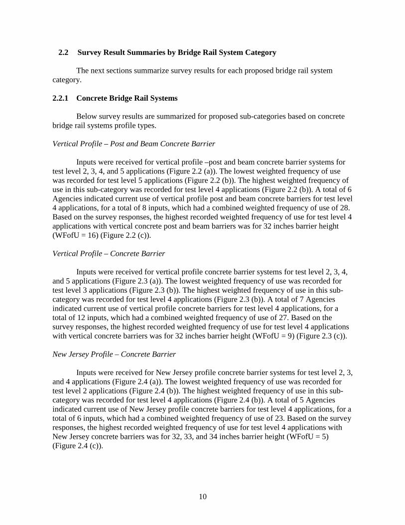
Vertical Profile – Post and Beam Concrete Barrier
Inputs were received for vertical profile –post and beam concrete barrier systems for test level 2, 3, 4, and 5 applications (Figure 2.2 (a)). The lowest weighted frequency of use was recorded for test level 5 applications (Figure 2.2 (b)). The highest weighted frequency of use in this sub-category was recorded for test level 4 applications (Figure 2.2 (b)). A total of 6 Agencies indicated current use of vertical profile post and beam concrete barriers for test level 4 applications, for a total of 8 inputs, which had a combined weighted frequency of use of 28. Based on the survey responses, the highest recorded weighted frequency of use for test level 4 applications with vertical concrete post and beam barriers was for 32 inches barrier height (WFofU = 16) (Figure 2.2 (c)). Vertical Profile – Concrete Barrier
Inputs were received for vertical profile concrete barrier systems for test level 2, 3, 4, and 5 applications (Figure 2.3 (a)). The lowest weighted frequency of use was recorded for test level 3 applications (Figure 2.3 (b)). The highest weighted frequency of use in this sub-category was recorded for test level 4 applications (Figure 2.3 (b)). A total of 7 Agencies indicated current use of vertical profile concrete barriers for test level 4 applications, for a total of 12 inputs, which had a combined weighted frequency of use of 27. Based on the survey responses, the highest recorded weighted frequency of use for test level 4 applications with vertical concrete barriers was for 32 inches barrier height (WFofU = 9) (Figure 2.3 (c)). New Jersey Profile – Concrete Barrier
Inputs were received for New Jersey profile concrete barrier systems for test level 2, 3, and 4 applications (Figure 2.4 (a)). The lowest weighted frequency of use was recorded for test level 2 applications (Figure 2.4 (b)). The highest weighted frequency of use in this sub-category was recorded for test level 4 applications (Figure 2.4 (b)). A total of 5 Agencies indicated current use of New Jersey profile concrete barriers for test level 4 applications, for a total of 6 inputs, which had a combined weighted frequency of use of 23. Based on the survey responses, the highest recorded weighted frequency of use for test level 4 applications with New Jersey concrete barriers was for 32, 33, and 34 inches barrier height (WFofU = 5) (Figure 2.4 (c)).

11
Single Slope Profile – Concrete Barrier
Inputs were received for single slope profile concrete barrier systems for test level 4 and 5 applications (Figure 2.5 (a)). The lowest weighted frequency of use was recorded for test level 5 applications (Figure 2.5 (b)). The highest weighted frequency of use in this sub-category was recorded for test level 4 applications (Figure 2.5 (b)). A total of 8 Agencies indicated current use of single slope profile concrete barriers for test level 4 applications, for a total of 14 inputs, which had a combined weighted frequency of use of 44. Based on the survey responses, the highest recorded weighted frequency of use for test level 4 applications with single slope concrete barriers was for 42 inches barrier height (WFofU = 18) (Figure 2.5 (c)). F-Shape Profile – Concrete Barrier
Inputs were received for F-Shape profile concrete barrier systems for test level 3, 4 and 5 applications (Figure 2.6 (a)). The lowest weighted frequency of use was recorded for test level 3 applications (Figure 2.6 (b)). The highest weighted frequency of use in this sub-category was recorded for test level 4 applications (Figure 2.6 (b)). A total of 13 Agencies indicated current use of F-Shape profile concrete barriers for test level 4 applications, for a total of 18 inputs, which had a combined weighted frequency of use of 67. Based on the survey responses, the highest recorded weighted frequency of use for test level 4 applications with F-Shape concrete barriers was for 32 inches barrier height (WFofU = 39) (Figure 2.6 (c)). Use of concrete barriers were then compared based on test level applications (Figure 2.7 and Figure 2.8). Table 2.2 summarizes survey results for concrete barriers. The highest WFofU for the concrete barrier category are summarized below:
• Test Level 2: vertical (WFofU = 9), vertical post and beam (WFofU = 7); New Jersey (WFofU = 2);
• Test Level 3: New Jersey (WFofU = 10), vertical and vertical post and beam (WFofU = 8), F-Shape (WFofU = 5);
• Test Level 4: F-Shape (WFofU = 67), single slope (WFofU = 44), vertical post and beam (WFofU = 29);
• Test Level 5: F-Shape (WFofU = 31), \ vertical (WFofU = 12), single slope (WFofU = 6).

12
Vertical Post-and-Beam Concrete Barrier
(a) Summary of Survey Data
(b) Test Levels Weighted Frequency of Use (c) Weighted Frequency of Use According to Barrier Height for TL-4 Applications
Figure 2.2 Summary for Vertical Post-and-Beam Concrete Barriers – Survey Results.
0
5
10
15
20
25
30
35
TL2 TL3 TL4 TL5
Wei
ghtin
g
Test Levels
Vertical Post-Beam Concrete Barriers
29 in, 17%
32 in , 45%
33 in, 7%
42 in, 3%
0%10%20%30%40%50%60%70%80%90%
100%
Perc
enta
ge (%
)
Barrier Height (in)
TL-4 Vertical Post-Beam Concrete Barriers
42 in
33 in
32 in
29 in

13
Vertical Concrete Barrier
(a) Summary of Survey Data
(b) Test Levels Weighted Frequency of Use (c) Weighted Frequency of Use According to Barrier Height for TL-4 Applications
Figure 2.3 Summary for Vertical Concrete Barriers – Survey Results.
05
1015202530
TL2 TL3 TL4 TL5
Wei
ghtin
g
Test Levels
Vertical Concrete Barriers
28 in, 7%
29 in, 26%
32 in, 33%
34 in, 26%
42 in, 7%
0%10%20%30%40%50%60%70%80%90%
100%
Perc
enta
ge (%
)
Barrier Height (in)
TL-4 Vertical Concrete Barriers
>42 in
42 in
34 in
32 in
29 in
28 in

14
New Jersey Concrete Barrier
(a) Summary of Survey Data
(b) Test Levels Weighted Frequency of Use (c) Weighted Frequency of Use According to Barrier Height for TL-4 Applications
Figure 2.4 Summary for New Jersey Concrete Barriers – Survey Results.
0
5
10
15
20
25
TL2 TL3 TL4 TL5
Wei
ghte
d Fr
eque
ncy
of U
se
Test Levels
New Jersey Concrete Barriers
32 in, 22%
33 in, 22%
34 in, 9%
35 in, 22%
36 in, 9%
40 in, 17%
0%10%20%30%40%50%60%70%80%90%
100%
Perc
enta
ge (%
)
Barrier Height (in)
TL-4 New Jersey Concrete Barriers
40 in
36 in
35 in
34 in
33 in
32 in

15
Single Slope Concrete Barrier
(a) Summary of Survey Data
(b) Test Levels Weighted Frequency of Use (c) Weighted Frequency of Use According to Barrier Height for TL-4 Applications
Figure 2.5 Summary for Single Slope Concrete Barriers – Survey Results.
0
10
20
30
40
50
TL2 TL3 TL4 TL5
Wei
ghtin
g
Test Levels
Single Slope Concrete Barriers
32 in, 20%
36 in, 25%
38 in, 0%
42 in, 41%
54 in, 9%
51 in, 5%
0%10%20%30%40%50%60%70%80%90%
100%
Perc
enta
ge (%
)
Barrier Height (in)
TL-4 Single Slope Concrete Barriers
51 in
54 in
42 in
38 in
36 in
32 in

16
F-Shape Concrete Barrier
(a) Summary of Survey Data
(b) Test Levels Weighted Frequency of Use (c) Weighted Frequency of Use According to Barrier Height for TL-4 Applications
Figure 2.6 Summary for F-Shape Concrete Barriers – Survey Results.
01020304050607080
TL2 TL3 TL4 TL5
Wei
ghtin
g
Test Levels
F-Shape Concrete Barriers
32 in, 58%
33 in, 7%34 in, 15%
42 in, 19%
0%10%20%30%40%50%60%70%80%90%
100%
Perc
enta
ge (%
)
Barrier Height (in)
TL-4 F-Shape Concrete Barriers
42 in
38 in
34 in
33 in
32 in

17
(a) TL-2 (b) TL-3
(c) TL-4 (d) TL-5 Figure 2.7 Weighted Frequency of Use for Concrete Barriers According to Test Levels – Survey Results.

18
Figure 2.8 Concrete Barriers – Survey Results Summary

19
Table 2.2 Weighted Frequency of Use Comparison for Concrete Barriers – Survey Results.
2.2.2 Metal-Only Bridge Rail Systems
Survey results are summarized for metal-only bridge rail systems below (Figure 2.9):
• Test Level 2: WFofU = 7; • Test Level 3: WFofU = 6; • Test Level 4: WFofU = 29.
The WFofU was then evaluated for two sub-category of the metal-only rail systems:
those that are deck-mounted and those that are side-mounted (Figure 2.10). In addition, investigation and comparison were conducted based on the number or railing members of the proposed sub-categories. Given a very limited number of inputs, no distinctions were attributed for w-beam, thrie-beam or tubular member: they are all here considered as contributing as one railing member. Deck-Mounted – Metal Only Inputs were received for deck-mounted, metal-only systems for test level 2, 3 and 4 applications (Figure 2.11). The lowest weighted frequency of use was recorded for test level 2 applications. The highest weighted frequency of use in this sub-category was recorded for test level 4 applications. A total of 6 Agencies indicated current use of deck-mounted metal-only barriers for test level 4 applications, for a total of 8 inputs, which had a combined weighted frequency of use of 26. Based on the survey responses, the highest recorded weighted frequency of use for test level 4 applications with deck-mounted metal-only barriers was for 2 railing members (WFofU = 15) (Figure 2.11 (a)). Side-Mounted – Metal Only Inputs were received for side-mounted, metal-only systems for test level 2 and 4 applications (Figure 2.11). The lowest weighted frequency of use was recorded for test level 2 applications. The highest weighted frequency of use in this sub-category was recorded for test

20
level 4 applications. A total of 5 Agencies indicated current use of side-mounted metal-only barriers for test level 4 applications, for a total of 5 inputs, which had a combined weighted frequency of use of 17. Based on the survey responses, the highest recorded weighted frequency of use for test level 4 applications with side-mounted metal-only barriers was for 3 railing members (WFofU = 12) (Figure 2.11 (b)).
Table 2.3 summarizes survey results for metal-only barriers. The highest WFofU for the metal-only barrier category are summarized below:
• Test Level 2: Side-Mounted (WFofU = 5), Deck-Mounted (WFofU = 2); • Test Level 3: Deck-Mounted (WFofU = 6); • Test Level 4: Deck-Mounted (WFofU = 12), Side-Mounted (WFofU = 17).
Table 2.3 Weighted Frequency of Use for Metal-Only Barriers – Survey Results.
2.2.3 Concrete-Metal Combined (Traffic-Only) Bridge Rail Systems Survey results are summarized for concrete-metal combined (traffic-only) bridge rail systems below (Figure 2.12 (a)):
• Test Level 2: WFofU = 14; • Test Level 3: WFofU = 25; • Test Level 4: WFofU = 75; • Test Level 5: WFofU = 13; • Test Level 6: WFofU = 2.
The WFofU was then evaluated for two sub-category of the concrete-metal combined (traffic-only) systems: those with metal railing mounted on a parapet and those with metal railing mounted on a curb (Figure 2.12 (b)). In addition, investigation and comparison were conducted based on the number or railing members of the proposed sub-categories.

21
Metal-Only Barriers
Figure 2.9 Weighted Frequency of Use for Metal-Only Barriers – Survey Results.
Metal-Only Barriers
Figure 2.10 Weighted Frequency of Use for Deck and Curb Mounted Metal-Only Barriers – Survey Results.
0
10
20
30
40
50
TL2 TL3 TL4 TL5Wei
ghte
d Fr
eque
ncy
of U
se
Test Levels
Metal-Only Rails

22
Metal-only Barriers Weighted Frequency of Use
(a) Side-Mounted Metal Railing
(b) Deck-Mounted Metal Railing Figure 2.11 Weighted Frequency of Use for Metal-Only Barriers with Railing Members
– Survey Results.

23
Traffic-Only Combined Barriers
(a) Traffic-Only Combined Barriers
(b) Parapet and Curb Weighted Frequency of Use
Figure 2.12 Weighted Frequency of Use for Traffic-Only Combined Barriers – Survey Results.

24
Concrete-Metal on Curb Inputs were received for concrete-metal combined system on curb for test level 2, 3 and 4 applications (Figure 2.12 (b)). The lowest weighted frequency of use was recorded for test level 2 applications. The highest weighted frequency of use in this sub-category was recorded for test level 4 applications (Figure 2.12 (b)). A total of 13 inputs were recorded from Agencies’ responses from concrete-metal combined rails on parapet, for test level 4 applications, with a combined weighted frequency of use of 45. Based on the survey responses, the highest recorded weighted frequency of use for test level 4 applications of concrete metal combined barriers on curb was for 2 metal railings (WFofU = 39) (Figure 2.13 (a)). Concrete-Metal on Parapet Inputs were received for concrete-metal combined system on parapet for test level 2, 3, 4, 5 and 6 applications (Figure 2.12 (b)). The lowest weighted frequency of use was recorded for test level 6 applications. The highest weighted frequency of use in this sub-category was recorded for test level 4 applications (Figure 2.12 (b)). A total of 11 inputs were recorded from Agencies’ responses from concrete-metal combined rails on parapet, for test level 4 applications, with a combined weighted frequency of use of 35. Based on the survey responses, the highest recorded weighted frequency of use for test level 4 applications of concrete metal combined barriers on parapet was for 2 metal railings (WFofU = 17) (Figure 2.13 (b)). Table 2.4 summarizes survey results for concrete-metal combined barriers – traffic only. The highest WFofU for this barrier category are summarized below:
• Test Level 2: combined on parapet, 2 metal railings (WFofU = 6); combined on parapet, 1 metal railing (WFofU = 4); combined on parapet, 3 metal railings, and combined on curb, 2 metal railings (WFofU = 3);
• Test Level 3: combined on curb, 2 metal railings (WFofU = 19); combined on parapet, 1 metal railing (WFofU = 6);
• Test Level 4: combined on curb, 2 metal railings (WFofU = 19); combined on parapet, 2 metal railings (WFofU = 17); combined on parapet, 3 metal railings (WFofU = 10);
• Test Level 5: combined on parapet, 2 metal railings (WFofU = 7); combined on parapet, 1 metal railing (WFofU = 6);
• Test Level 6: combined on parapet, 1 metal railing (WFofU = 2).

25
Configuration Weighted Frequency of Use
(a) Traffic-Only Combined Barriers on Curb
(b) Traffic-Only Combined Barriers on Parapet Figure 2.13 Weighted Frequency of Use for Traffic-Only Combined Barriers with
Railing Members – Survey Results.

26
Table 2.4 Weighted Frequency of Use for Traffic-Only Combined Barriers with Railing Members – Survey Results.

27
2.2.4 Combination Traffic-Pedestrian Bridge Rail Systems Survey results are summarized for combination traffic-pedestrian bridge rail systems below (Figure 2.14):
• Test Level 2: WFofU = 27; • Test Level 3: WFofU = 32; • Test Level 4: WFofU = 61; • Test Level 5: WFofU = 5;
The WFofU was then evaluated for two sub-category of the combination traffic-pedestrian rail systems: those with a sidewalk and those without a sidewalk (Figure 2.14). Combination Traffic-Pedestrian – With Sidewalk Inputs were received for combination traffic-pedestrian rails with sidewalk for test level 2, 3, 4 and 5 applications (Figure 2.14 (b)). The lowest weighted frequency of use was recorded for test level 5 applications. The highest weighted frequency of use in this sub-category was recorded for test level 4 applications. A total of 11 Agencies indicated current use of combination traffic-pedestrian rails with sidewalk for test level 4 applications, for a total of 15 inputs, which had a combined weighted frequency of use of 39. Combination Traffic-Pedestrian – Without Sidewalk Inputs were received for combination traffic-pedestrian rails without sidewalk for test level 2, 3 and 4 applications (Figure 2.14 (b)). The lowest weighted frequency of use was recorded for test levels 2 and 3 applications. The highest weighted frequency of use in this sub-category was recorded for test level 4 applications. A total of 5 Agencies indicated current use of combination traffic-pedestrian rails with sidewalk for test level 4 applications, for a total of 7 inputs, which had a combined weighted frequency of use of 22. Table 2.5 summarizes survey results for combination traffic-pedestrian rails. The highest WFofU for this barrier category are summarized below:
• Test Level 2: combination with sidewalk (WFofU = 17), combination without sidewalk (WFofU = 10);
• Test Level 3: combination with sidewalk (WFofU = 12), combination without sidewalk (WFofU = 10);
• Test Level 4: combination with sidewalk (WFofU = 39), combination without sidewalk (WFofU = 22);
• Test Level 5: combination with sidewalk (WFofU = 5).

28
Combination Traffic-Pedestrian Barriers
(a) Combination Traffic-Pedestrian Barriers
(b) With and Without Sidewalk Weighted Frequency of Use
Figure 2.14 Weighted Frequency of Use for Combination Traffic-Pedestrian Barriers – Survey Results.

29
Table 2.5 Weighted Frequency of Use for Combination Traffic-Pedestrian Barriers –
Survey Results.
2.2.5 Wood Bridge Rail Systems One Agency inputted two wood bridge rail systems, one for test level 1 and one for test level 2. Both wood systems had a WFofU of 2. 2.2.6 Noise-Wall Bridge Rail Systems One Agency inputted two noise wall bridge rail systems, both fur test level 4 applications, for a combine WFofU of 4. 2.2.7 Retrofit Bridge Rail Systems Survey results are summarized for retrofit bridge rail systems below:
• Test Level 2: WFofU = 2; • Test Level 3: WFofU = 4; • Test Level 4: WFofU = 12;

30
2.3 Conclusions Table 2.6 summarizes ranking based on weighted frequency of use for each proposed barrier category. Table 2.7 through Table 2.10 summarize overall ranking of railing system types based on weighted frequency of use for test level 2 through test level 5, respectively. These prioritized railing types were considered for further investigation and evaluation for MASH equivalency.

31
Table 2.6 Ranking Based on Weighted Frequency of Use per Category – Survey Results.

32
Table 2.7 TL-2 Ranking Based on Weighted Frequency of Use – Survey Results.

33
Table 2.8 TL-3 Ranking Based on Weighted Frequency of Use – Survey Results.

34
Table 2.9 TL-4 Ranking Based on Weighted Frequency of Use – Survey Results.

35
Table 2.10 TL-5 Ranking Based on Weighted Frequency of Use – Survey Results.


37
3 METHODOLOGY FOR EVALUATING TEST LEVEL EQUIVALENCY In the development of MASH, several changes and additions were incorporated to reflect the changing fleet of vehicles using the highway network. Some of these changes include increasing the weight and body style of the pickup truck vehicle used in Test No. 11. Furthermore, the weight of the passenger car vehicle increased for Test No. 10 and the impact angle increased from 20 to 25 degrees. These changes may result in increased impact forces, vehicle snagging, vehicle deformation, vehicle accelerations, and barrier deflections when compared to NCHRP Report 350 Test impact and vehicle conditions. As part of the effort to evaluate equivalency between NCHRP Report 350 and MASH test levels, three key criteria have been explored. The three criteria are stability, strength, and geometrics. Stability relates to all of the characteristics of the barrier that affects vehicle stability, such as barrier height, barrier shape, and barrier stiffness. The strength category consists of all the features of the barrier that affect the ability of the barrier to effectively contain and redirect the vehicle back into the travel lane-shoulder and all factors of the barrier that prevents the vehicle from penetrating through the barrier. The geometric category is all geometric features of the bridge rail that affect occupant risk criteria in MASH. These include post setback, clear opening between longitudinal rail elements, and available vertical contact surface area. These factors can influence key performance metrics that include vehicle snagging, occupant compartment deformation, and acceleration-based occupant risk indices. Details of these evaluations and the relevance of the results to assessing test level equivalencies are discussed below. 3.1 Test Level 2 (TL-2) and Test Level 3 (TL-3) Bridge Rail Systems 3.1.1 Stability Requirements The relative stability of the pickup truck design test vehicle plays an important role in regard to rail height requirements necessary for acceptable impact performance for Test Level 2 (TL-2) and TL-3. If the stability of the MASH 2270P pickup truck design vehicle is equivalent or improved compared to the NCHRP Report 350 2000P pickup truck design vehicle, then minimum rail height requirements established under NCHRP Report 350 could be acceptable under MASH. This is one of the factors that will assist with the evaluation of test level equivalency between the two guidelines. A stability criterion that can help assess the relative stability of the two pickup truck design test vehicles is the Static Stability Factor (SSF). The SSF of a vehicle is an at-rest calculation of its rollover resistance based on its geometric properties. The SSF is calculated using Equation 3.1: 𝑆𝑆𝑆𝑆𝑆𝑆 = 𝑇𝑇
2𝐻𝐻
where
Equation 3.1

38
T = Track width H = Center of mass location of the vehicle above the ground surface The track width (T) is the distance between the centerline of the left side and right side wheels of the vehicle. As the track width of a vehicle increases, the stability of the vehicle will also increase. As the center of mass location of the vehicle above the ground (H) increases, the stability of the vehicle will decrease. A larger SSF value for a vehicle represents a more stable vehicle. From NCHRP Report 350, the specified track width (T) of the 2000P pickup truck is 65 inches ± 6 inches. An average track width of 63.5 inches was found by averaging track widths for 10 different NCHRP Report 350 pickup truck test vehicles. From NCHRP Report 350, the center of mass location of the 2000P above the ground (H) is 28 inches ± 2 inches. An average value of 26.66 inches was found by averaging C.G. heights for 5 different NCHRP Report 350 pickup truck test vehicles. From MASH, the specified track width (T) of a 2270P pickup truck is 67 inches ± 1.5 inches. An average value of 68.3 inches was found by averaging track widths for 10 different MASH pickup truck test vehicles. From MASH, the center of mass location of the 2270P above the ground (H) is a minimum of 28 inches. An average value of 28.4 inches was found by averaging C.G. heights for 10 different MASH 2270P pickup truck test vehicles. The SSF can be determined for both the NCHRP Report 350 and MASH pickup truck vehicles using the average values for track width and center of mass location of the vehicle above the ground. The SSF for the NCHRP Report 350 and MASH pickup truck vehicles is 1.19 and 1.20, respectively. Based on this information, the MASH 2270P vehicle is similar or perhaps slightly improved in regard to static stability compared to the NCHRP Report 350 pickup truck. This has been anecdotally observed by TTI researchers through observation of full-scale crash tests. Although the MASH pickup truck has a higher C.G. height than the NCHRP Report 350 pickup truck, any associated effect on stability is offset by an increase in track width. Another, more direct means of comparing the stability of the MASH and NCHRP Report 350 pickup truck design test vehicles is crash test data. Unfortunately, at this time, few bridge rails have been tested to both NCHRP Report 350 and MASH guidelines that permit a direct comparison of vehicle stability and other performance factors. Variations in impact conditions (within specified tolerances) can also complicate the comparison. Two bridge rail systems that have been tested under TL-3 impact conditions under both criteria are the single slope traffic rail (SSTR) and New Jersey safety shape (NJSS) barrier. The Texas version of the SSTR was crash tested under both NCHRP Report 350 and MASH Test 3-11 and, therefore, provides the basis for direct comparison of vehicle stability and other test metrics. Data for NCHRP Report 350 Test 3-11 was obtained from Research Report FHWA-RD-98-043 entitled “Testing of State Roadside Safety Systems, Volume VIII: Appendix G – Crash Testing and Evaluation the Single Slope Bridge Rail.” In this test, a 32-inch tall single slope rail was impacted by the 2000P pickup truck at a speed of 60.4 mi/h and

39
an angle of 25.5 degrees. The maximum pitch and roll angles of the pickup truck during the test were 7 degrees and 30 degrees, respectively. MASH Test 3-11 was performed on a 36-inch tall single slope barrier under TxDOT Project 9-1002. Details of the test can be found in Research Report 9-1002-3 entitled “MASH Test 3-11 of the TxDOT Single Slope Bridge Rail (Type SSTR) on Pan-Formed Bridge Deck.” The 2270P pickup truck impacted the single slope rail at a speed of 63.8 mi/h and an angle of 24.8 degrees. The maximum pitch roll angles for this test were 8 degrees and 26 degrees, respectively. When comparing the vehicle stability data from the NCHRP Report 350 and MASH crash tests, it can be seen that the maximum pitch angles for both tests are very similar, and the maximum roll angle from MASH test 3-11 is slightly lower than the maximum roll angle from the NCHRP Report 350 crash test. It should be noted that the MASH test had an impact severity that was 20% greater than the NCHRP Report 350 test based on the actual impact conditions. A 32-inch tall New Jersey safety shape barrier has also been evaluated to TL-3 under both NCHRP Report 350 and MASH 3-11. The NCHRP Report 350 test is documented in Research Report FHWA/TX-04/9-8132-1, “Testing and Evaluation of the Florida Jersey Safety Shaped Bridge Rail.” The 2000P pickup truck impacted the NJSS rail at a speed of 61.1 mi/h and an angle of 26.4 degrees. The maximum pitch angle and maximum roll angle of the pickup truck during the test were 19.3 degrees and 18.6 degrees, respectively. MASH test 3-11 on the 32-inch NJSS was performed under NCHRP Project 22-14(3) and is documented in NCHRP Research Results Digest 349, "Evaluation of Existing Roadside Safety Hardware Using Manual for Assessing Safety Hardware (MASH)." In this test, the 2270P pickup truck impacted the NJSS at a speed and angle of 62.6 mi/h and 25.2 degrees, respectively. The maximum pitch angle and maximum roll angle recorded during the test were 16 degrees and 29 degrees, respectively. The impact severity of the MASH test was approximately 9% greater than the NCHRP Report 350 test. A comparison of the vehicle stability during the test shows that while the pitch angle was slightly less for the MASH test, the roll angle was significantly greater. The evaluation of test data is based on a small sample and is inconclusive. While the pitch angle was comparable in both tests for both systems, the roll angle differed. For the single slope barrier, the roll angle in MASH test 3-11 was 4 degrees less than the corresponding NCHRP Report 350 test, while testing of the New Jersey safety shape barrier resulted in a roll angle that was 10 degrees more in the MASH test. In both tests, the impact severity of the MASH test exceeded that of the NCHRP Report 350 test. However, it is noted that the impact severity of MASH Test 3-11 is 13.5% greater than NCHRP Report 350 Test 3-11 by design based on nominal impact conditions.

40
To assist in evaluating the equivalency between NCHRP 350 and MASH TL-3, finite element simulations were used to determine minimum rail height for MASH TL-3. To determine minimum rail height MASH test level 3, finite element (FE) analysis was used to simulate impacts of a truck against a rigid barrier. The height of the barrier was parametrically varied to arrive at a suggested minimum rail height. The FE simulations with varying barrier height were analyzed to determine effect of rail height on vehicle kinematics and stability.
Finite element analysis was performed using LS-DYNA, which is a commercial free FE software commonly used for crashworthiness analysis. The rigid concrete barriers were modeled with rigid material representation in all of the analyses. This modelling technique was done because no significant failure of deflection of the barrier was expected due to vehicle impact. The MASH truck model was primarily developed by the National Crash Analysis Center. Modifications were made to the truck model to improve performance when impacting the rigid barrier.
To evaluate the effect of rail height on vehicle stability and kinematics, researchers performed FE simulations of the MASH truck with a rigid barrier at varying heights. In order to verify the kinematics of the MASH truck FE model a simulation was conducted on a 32-inch vertical wall. This simulation was compared to a MASH 3-11 crash test that was conducted on a 32-inch vertical MSE wall. Figure 3.1 shows a comparison of sequential photographs from the simulation and full-scale crash test. In addition, the roll and pitch angles were plotted and compared for the simulation and full-scale crash test as seen in Figure 3.2. The simulation roll angle reaches a peak of about 5 degrees less than the full-scale crash test and the pitch angles reached a similar peak. Overall the behavior of the FE pickup truck performed well when compared to the full-scale crash test.
To determine minimum rail height a total of three simulations were conducted. The simulations were conducted with a vertical rigid barrier at a height of 27, 28, and 29 inches. Figure 3.3 through Figure 3.5 show sequential photographs of the three simulations that were performed. The simulation with a 27-inch barrier height resulted in rollover of the truck. The simulation with a 28-inch barrier height did not rollover but was on the edge of instability. The simulation with a 29-inch barrier height did roll after impact with the vertical wall but was fairly stable throughout the impact event. With the analysis of this FE study the recommended minimum rail height for MASH TL-3 is 29 inches.

41
0.000 s
0.086 s
0.171 s
0.257 s Figure 3.1 Sequential Photographs of FE Simulation and Full-Scale Crash Test(12).

42
0.340 s
0.426 s
0.512 s
0.597 s Figure 3.1. Sequential Photographs of FE Simulation and Full-Scale Crash Test(12)
(Continued).

43
Figure 3.2 Comparison of Roll and Pitch Angle for Full-Scale Crash Test and FE
Simulation.
-45
-40
-35
-30
-25
-20
-15
-10
-5
0
5
10
0 0.1 0.2 0.3 0.4 0.5 0.6 0.7 0.8 0.9 1
Ang
le (d
egre
es)
Time (s)
Full-Scale Test Roll Angle FE Simulation Roll Angle
Full-Scale Test Pitch Angle FE Simulation Pitch Angle

44
0.000 s 0.450 s
0.150 s 0.600 s
0.300 s 0.750 s Figure 3.3 Sequential Photographs of FE Simulation with 27-inch Barrier Height.

45
0.000 s 0.450 s
0.150 s 0.600 s
0.300 s 0.750 s Figure 3.4 Sequential Photographs of FE Simulation with 28-inch Barrier Height.

46
0.000 s 0.450 s
0.150 s 0.600 s
0.300 s 0.750 s Figure 3.5 Sequential Photographs of FE Simulation with 29-inch Barrier Height.
3.1.2 Strength Requirements The strength requirements for a bridge rail system are related to the lateral load imparted to the barrier by the design test vehicle during an impact. Impact Severity (IS) is one parameter related to lateral load imparted to a barrier, and is often used as a means to compare the relative structural demand on a barrier associated with different impact conditions. Impact Severity is calculated using Equation 3.2: 𝐼𝐼𝑆𝑆 = 1
2𝑀𝑀(𝑉𝑉𝑉𝑉𝑉𝑉𝑉𝑉𝑉𝑉)2
Equation 3.2

47
where: M = Mass of vehicle V = Vehicle impact velocity Ɵ = Vehicle impact angle Test 11 with the pickup truck design test vehicle is the structural adequacy test for Test Levels 2 and 3. For Test 11, the impact speed and angle did not change between NCHRP Report 350 and MASH. However, the weight of the pickup truck increased from 4,400 lb under NCHRP Report 350 to 5,000 lb under MASH. Table 3.1 summarizes the impact conditions and calculated impact severities for Test Levels 2 and 3 for Test 11 with the pickup truck design test vehicle for both NCHRP Report 350 and MASH. There is a 13.6% increase in Impact Severity from the NCHRP Report 350 and MASH that reflects the increase in vehicle weight. This higher impact severity indicates that MASH Test 11 with the 2270 pickup truck will exert a higher impact force to the bridge rail system than NCHRP Report 350 Test 11 with 2000P pickup truck. In other words, with regard to Impact Severity, MASH Test 11 is more severe than NCHRP Report 350 Test 11.
Table 3.1 Impact Severity for Test 11.
Test Level
Test Vehicle
Vehicle Weight (lbs.)
Impact Speed, V
(mi/h)
Impact Angle, θ (degrees)
Impact Severity, IS (k-ft) Percent
Difference (%)
350 MASH 350 MASH 350 MASH 350 MASH
2 Pickup Truck
4400 5000 44 44 25 25 49.7 56.5 13.6
3 Pickup Truck 4400 5000 62 62 25 25 101.4 115.2 13.6
The calculation of Impact Severity provides an indication that impact forces should be higher under MASH than NCHRP Report 350. The actual impact forces imparted to a barrier under a prescribed set of impact conditions are related to a number of factors including barrier stiffness, barrier height, and barrier shape. Generally speaking, higher loads will be transmitted to a barrier with a higher stiffness. Many bridge rail systems behave in a nearly rigid manner with low dynamic deflections under design impact conditions. LS-DYNA impact simulations were performed to determine impact forces for MASH Test 11 for TL-3. The impact simulations involved the 2270P pickup truck impacting a rigid vertical parapet at the prescribed impact speed of 62 mi/h and a 25 degree impact angle. Both the magnitude and resultant height of the applied impact force was determined from the simulations. Similar impact simulations were performed for NCHRP Report 350 Test 11 with the 2000P pickup truck for comparison to MASH impact forces to assist with evaluation of test level equivalencies between the two guidelines. Figure 3.6 shows the simulation setup for NCHRP Report 350 and MASH test vehicles.

48
(a) MASH Pickup Truck (b) NCHRP Report 350 Pickup Truck Figure 3.6 Simulation Setup.
For each LS-DYNA simulation that was performed, researchers determined the lateral load applied to the barrier due to vehicle impact. The load was calculated by summing contact forces on the barrier during impact. In addition to determining lateral impact load, researchers also determined the resultant height at which the lateral load is being applied on the barrier. This was accomplished using LS-DYNA contact force transducers, which allow contact force to be measured along the height of the barrier. For each simulation, contact forces were measured at 1-inch increments along the height of the barrier. Figure 3.7 shows the resulting 50-ms average force distribution acting along the height of the barrier at the time in which peak lateral force is observed.
The results of the impact simulations are shown in Table 3.2. The NCHRP Report 350 impact load was estimated to be 61 kips for TL-3. The MASH TL-3 impact force increased to 71 kips. This indicates that increased barrier capacity will be required to meet MASH. It is noted that the 61 kip load for NCHRP Report 350 TL-3 is greater than the design load of 54 kips specified in Section 13 of the AASHTO LRFD Bridge Design Specification that has been the basis of bridge rail design for NCHRP Report 350 TL-3 impact conditions for many years. If this value is indeed accurate, the successful performance of NCHRP Report 350 TL-3 bridge rails may be attributed to several factors: (1) the computed ultimate capacity for most rail systems exceeds the design impact force, (2) the analysis procedures used to determine structural capacity of bridge rails are conservative in nature, (3) design is based on minimum specifications for material strength (concrete, rebar, steel) and actual material strengths are typically greater in practice, and (4) not all bridge rail systems are perfectly rigid, and any deflection or deformation will reduce forces during an impact.

49
(a) NCHRP Report 350 TL-3
(b) MASH TL-3
Figure 3.7 50 ms Average Lateral Force along Height of Barrier.
0
5
10
15
20
25
30
0 1 2 3 4 5 6 7 8 9
Bar
rier H
eigh
t (in
)
50-ms avg. Force (kips)
0
5
10
15
20
25
30
0 2 4 6 8 10 12 14 16 18
Bar
rier H
eigh
t (in
)
50-ms avg. Force (kips)

50
It is important to consider not only the magnitude of the impact force, but also its resultant height of application. For instance, the 54-kip design load specified for NCHRP Report 350 TL-3 bridge rails is applied at a height of 24 inches. Thus, the moment that an NCHRP Report 350 TL-3 bridge rails were designed for is 54 kips x 24 inches = 1,296 kip-inches. With new finite element simulation technology, the distribution of the lateral force on the barrier can be quantified, and the force distribution can be used to calculate the resultant height of the load. For NCHRP Report 350 TL-3 impact conditions, the impact simulations performed under Phase I indicated a 61 kip lateral force at a resultant height of 18 inches. This equates to a moment of 61 kips x 18 inches = 1,098 kip-inches. Thus, while the 61 kip load is 13% higher than the specified design load of 54 kips, the lower resultant height of the load produces a moment that is 15% less than the current design moment. This indicates that rails designed according to current criteria may have significant reserve capacity. As shown in Table 3.2, the lateral impact force associated with MASH TL-3 impact conditions (as determined through finite element impact simulations) is 71 kips, which is 16% greater than the NCHRP Report 350 load. However, the associated moment (71 kips x 19.5 inches = 1,385 kip-inches) is within 7% of the design moment used for NCHRP Report 350 bridge rails. Thus, an NCHRP Report 350 TL-3 bridge rail may have sufficient capacity to accommodate MASH impact conditions, especially considering the conservative nature of the strength analysis methodology and material properties.
Table 3.2 Impact Forces for Test 11.
NCHRP Report 350 MASH
Lateral Impact Force (kips)
Resultant Force Height (in)
Lateral Impact Force (kips)
Resultant Force Height (in)
TL-3 61 18 71 19.5 3.1.3 Geometric Requirements Geometric design requirements are intended to help mitigate the propensity for vehicle snagging on bridge rail components. Severe snagging can result in higher occupant risk through increased vehicle accelerations and occupant compartment deformation. Snagging contact is relevant for beam-and-post bridge rail systems that have discrete elements such as posts, rail splices, and connection hardware that vehicle components can snag on. These bridge rails may be metal beam-and-post, concrete beam-and-post, or a beam-and-post section on top of a concrete curb or parapet. The impact severity of MASH Test 10 has increased dramatically due to an increase in both vehicle weight and impact angle. Because this may result in a propensity for more severe snagging compared to NCHRP Report 350 Test 10, rail geometric requirements must be carefully considered when investigating test level equivalencies. Although testing of beam-and-post bridge rails under MASH has been limited to date, failure of Test 10 with the 1100C small car due to snagging induced occupant compartment deformation or acceleration-based occupant risk indices has not been observed. This may be due to improved vehicle design and an effective increase in occupant compartment deformation thresholds under MASH.

51
NCHRP Report 350 did not have a quantitative threshold for maximum occupant compartment deformation. It stated under Criterion D that “Deformations of, or intrusions into, the occupant compartment that could cause serious injuries should not be permitted.” The maximum occupant compartment deformation for MASH varies with location in the vehicle. For the wheel/foot well and toe pan areas, which are the areas most likely to be affected by snagging induced deformation, the maximum allowable occupant compartment deformation is limited to 9.0 inches. For the floor pan and transmission tunnel areas, the maximum allowable occupant compartment deformation is limited to 12.0 inches. The geometric relationships for bridge railings contained in Section 13 AASHTO LRFD Bridge Design Specifications were empirically developed based on a review of crash test data. The impact performance of different rail systems was analyzed with respect to different geometric characteristics that relate to the potential for vehicle snagging and high vehicle accelerations. The resulting geometric relationships for bridge rail design are contained in Figure A13.1.1-2 and Figure A13.1.1-3 in the AASHTO LRFD Bridge Design Specifications, which are reproduced as Figure 3.8 and Figure 3.9 below. Figure 3.8 pertains to the potential for wheel, bumper or hood snagging contact with a discrete post. Figure 3.9 relates post setback distance to contact area provided by the rail members as a function of the post setback distance and ratio of rail contact width to rail height. Note that these relationships apply to beam-and post-type bridge rail systems. These systems have openings between longitudinal rail elements and discrete vertical elements that can interact with vehicle components. The relationships are not applicable to solid faced bridge rails such as solid concrete shapes.
As can be seen in the respective figures, the crash test data upon which these relationships are based pertains to NCHRP Report 230. The relationships have not been updated to reflect NCHRP Report 350 vehicles and impact conditions, but are still commonly applied to bridge rail design. In fact, it would be expected that most NCHRP Report 350 bridge rail systems would satisfy these design relationships. The question becomes whether these relationships remain valid for MASH bridge rail systems. Sufficient crash test data does not yet exist for such relationships to be confidently verified or revised for MASH test vehicles and impact conditions. Nonetheless, some value can still be derived from evaluating rail geometry of bridge rail systems tested to MASH criteria. Under this project, TTI researchers analyzed the geometry of MASH and NCHRP Report 350 tested bridge rail systems in relation to current guidelines. In addition, these bridge rail systems were broken down into different beam- and post-type categories including concrete beam-and-post, metal beam-and-post deck or side mounted, metal beam-and-post curb mounted, and metal beam-and-post parapet mounted. Curb mounted systems are defined herein as those with a concrete height equal to or less than 11 inches above grade. Parapet mounted systems are defined herein as those with a concrete height equal to or greater than 12 inches above grade with a metal rail on top.

52
Figure 3.8 AASHTO Figure A13.1.1-2 – Potential for Wheel, Bumper, or Hood Impact with Post.
Figure 3.9 AASHTO Figure 13.1.1-3 – Post Setback Criteria.

53
For each bridge rail system tested in accordance with MASH criteria, post setback distance, ratio of contact width to height, and vertical clear opening were determined or calculated. Table 3.3 shows the MASH bridge rail systems and their geometric parameters. Geometric data for NCHRP Report 350 tested bridge rail systems were obtained from NCHRP Project No. 22-19, “Aesthetic Concrete Barrier and Bridge Rail Design,” under which a comprehensive review of NCHRP Report 350 crash tested bridge rails was performed. Figure 3.10 and Figure 3.11 show the geometric data plotted for NCHRP Report 350 and MASH beam-and-post systems tested with the small car vehicle, and Figure 3.12 and Figure 3.13 show the geometric data plotted for NCHRP Report 350 and MASH beam-and-post systems tested with the pickup truck vehicle.
One observation of interest related to rail geometry and snagging severity is that the pickup truck typically used in full-scale crash tests under MASH criteria is much more likely to experience complete wheel separation than the typical pickup truck used by most testing labs under NCHRP Report 350. The ½-ton, 4-door Dodge Ram Quad Cab has been used extensively for MASH crash testing and is expected to continue to be the vehicle of choice by testing labs based on is availability and cost. TTI researchers have noted a propensity for this pickup truck to experience suspension failure and complete wheel separation during crash testing. A photo of a Dodge Quad Cab pickup truck showing typical suspension failure and wheel separation after a MASH TL-3 crash test is shown in Figure 3.14.
Under NCHRP Report 350, the most common pickup truck test vehicle was a ¾-ton, 2-door, Chevrolet C2500. Experience with this vehicle was that while damage to the front suspension (e.g., broken tie rod) was common, complete suspension failure and wheel separation was not. A photo of a Chevrolet C2500 pickup truck after an NCHRP Report 350 TL-3 crash test is shown as Figure 3.15. In this test, components of the suspension were damaged, but the wheel remained with the vehicle throughout the impact. This difference in suspension performance can potentially have an effect on numerous factors such as vehicle stability, occupant compartment deformation, and occupant risk. Suspension deformation is caused by the impact forces generated through contact of the vehicle with the barrier and may or may not involve “snagging” of the wheel or other components of the vehicle on elements of the barrier system. Vehicle snagging in particular, and high forces applied to the suspension in general, can result in greater vehicle deformation and increased vehicle accelerations. Occupant compartment deformation often occurs as a result of the wheel assembly being pushed rearward into the firewall and floorpan. Increased accelerations can result in higher occupant ridedown accelerations and, since the suspension forces are typically acting below the vehicle center of gravity (C.G.), greater vehicle instability.

54
Table 3.3 MASH Bridge Rail Systems and Geometry.
Bridge Rail System Post Setback Distance (in)
Vertical Clear Opening (in)
Ratio of Contact Width to Height
TxDOT T101 Bridge Rail 6.25 14.75 0.45 TxDOT T1F Bridge Rail 6.88 10.5 0.55 TxDOT T223 Bridge Rail 4.5 13.0 0.60 TxDOT T131 Bridge Rail 4.0 11.0 0.42
TxDOT 131RC Bridge Rail 6.0 7.0 0.64 RIST Bridge Rail 7.87 13.0 0.47
TxDOT Picket Rail 3.5 8.0 0.49 Lake Pontchartrain Bridge Rail 2.75 8.0 0.48
Lake Pontchartrain Bridge Rail Option 2 4.5 8.0 0.44 Dong-A Steel Bridge Rail 7.87 11.8 0.45 TxDOT T224 Bridge Rail 3.5 12.0 0.70
TBTA Bridge Rail 5.0 6.0 0.43 TxDOT Type C2P Bridge Rail 6.38 10.5 0.42 Pulaski Skyway Bridge Parapet 6.0 19.0 0.57
ST-10 Bridge Rail 5.50 10.0 0.42
Figure 3.10 MASH and NCHRP Report 350 Small Car Test Data – Post Setback versus Ratio of Rail Contact Width to Height.
0
0.1
0.2
0.3
0.4
0.5
0.6
0.7
0.8
0.9
0 2 4 6 8 10 12
Rat
io o
f Rai
l Con
tact
Wid
th to
Hei
ght
Post Setback Distance (in)
350 TL-3
MASH TL-3
350 TL-4
MASH TL-4
MASH TL-5
350 Failed Test
Preferred
Not Recommended
T202

55
Figure 3.11 MASH and NCHRP Report 350 Small Car Test Data – Post Setback versus Vertical Clear Opening.
0
2
4
6
8
10
12
14
16
18
20
0 2 4 6 8 10 12 14
Ver
tical
Cle
ar O
peni
ng (i
n)
Post Setback Distance (in)
350 TL-3
MASH TL-3
350 TL-4
MASH TL-4
MASH TL-5
350 Failed Test
High Potential
Low Potential
T202

56
Figure 3.12 MASH and NCHRP Report 350 Pickup Truck Test Data – Post Setback versus Ratio of Rail Contact Width to Height.
0
0.1
0.2
0.3
0.4
0.5
0.6
0.7
0.8
0.9
0 2 4 6 8 10 12
Rat
io o
f Rai
l Con
tact
Wid
th to
Hei
ght
Post Setback Distance (in)
350 TL-3
MASH TL-3
350 TL-4
MASH TL-4
MASH TL-5
350 Failed Tests
MASH Failed Tests
Not Recommended
Preferred
Oregon Bridge Rail
F411
NY (2-member)
T4 (A)Bridge
RailT77
T101CaltransT131

57
Figure 3.13 MASH and NCHRP Report 350 Pickup Truck Test Data – Post Setback versus Vertical Clear Opening.
0
5
10
15
20
25
30
0 2 4 6 8 10 12 14
Ver
tical
Cle
ar O
peni
ng (i
n)
Post Setback Distance (in)
350 TL-3
MASH TL-3
350 TL-4
MASH TL-4
MASH TL-5
350 Failed Tests
MASH Failed Tests
High Potential
Low Potential
T4 (A)Bridge
Rail
F411
T77
Oregon Bridge Rail
NY (2-member)
T101
T131Caltrans

58
Figure 3.14 MASH 2270P Suspension after MASH TL-3 Crash Test(14).
Figure 3.15 NCHRP Report 350 2000P Suspension after NCHRP Report 350 TL-3
Crash Test(15).

59
If the wheel assembly readily releases from the vehicle during an impact, it can limit the magnitude of vehicle accelerations and vehicle deformation. By releasing during an impact, the wheel assembly acts as a type of fuse that limits further increases in force and deformation associated with the interaction of the suspension system and the barrier. Anecdotally, this appears to be the case with the Dodge Ram. Although the significance of this behavior cannot be fully quantified without more comparative crash tests, improved performance could be expected for some barriers in terms of vehicle stability, occupant compartment deformation, and ridedown accelerations when comparing the MASH 2270P to the NCHRP Report 350 2000P pickup trucks. This effect is expected to be greater in TL-3 impacts than TL-2 impacts due to the fact that the higher impact severity will generate greater impact forces. 3.1.4 Geometric Requirements for Specific Bridge Rail Categories Further evaluation of the test level equivalency of NCHRP Report 350 bridge rail systems was performed by separating the bridge rails into five different categories. These categories include Solid Concrete Parapet, Concrete Beam-and-Post, Metal Beam-and-Post Deck Mounted, Metal Beam-and-Post Curb Mounted, and Metal Beam-and-Post on Concrete Parapet. The purpose for this categorization is that initial investigation of the geometric relationships for MASH equivalency did not result in a strong correlation. As such, by breaking down the bridge rails into different categories, test level equivalencies could possibly be made for the individual category of NCHRP Report 350 bridge rails. Solid Concrete Parapet This category of bridge rails includes rails such as the single slope barrier, New Jersey Safety Shape (NJSS) barrier, F-Shape barrier, vertical wall barrier, and any other closed profile concrete barriers. The Texas version of the single slope bridge rail, which has an 11-degree slope on the traffic face, was crash tested under both NCHRP Report 350 and MASH Test 3-11 and, therefore, provides the basis for direct comparison of vehicle stability and other test metrics. Data for NCHRP Report 350 Test 3-11 was obtained from Research Report FHWA-RD-98-043 entitled “Testing of State Roadside Safety Systems, Volume VIII: Appendix G – Crash Testing and Evaluation the Single Slope Bridge Rail.” In this test, a 32-inch tall single slope rail was impacted by the 2000P pickup truck at a speed of 60.4 mi/h and an angle of 25.5 degrees. The maximum pitch and roll angles of the pickup truck during the test were 7 degrees and 30 degrees, respectively. MASH Test 3-11 was performed on a 36-inch tall single slope barrier under TxDOT Project 9-1002. Details of the test can be found in Research Report 9-1002-3 entitled “MASH Test 3-11 of the TxDOT Single Slope Bridge Rail (Type SSTR) on Pan-Formed Bridge Deck.” The 2270P pickup truck impacted the single slope rail at a speed of 63.8 mi/h and an angle of 24.8 degrees. The maximum pitch roll angles for this test were 8 degrees and 26 degrees, respectively.

60
MASH Test 3-10 was performed on the Caltrans version of the single slope bridge rail, which has a 9-degree slope on the traffic face. The 1100C small car vehicle impacted the Caltrans Type 60 barrier at a speed of 61.2 mph and an angle of 25.7 degrees. The test was considered a pass according to MASH Test 3-10 evaluation criteria. The final report was in progress during the preparation of this report, so specific results from the test were not available. A 32-inch tall New Jersey safety shape barrier has also been evaluated to TL-3 under both NCHRP Report 350 and MASH 3-11. The NCHRP Report 350 test is documented in Research Report FHWA/TX-04/9-8132-1, “Testing and Evaluation of the Florida Jersey Safety Shaped Bridge Rail.” The 2000P pickup truck impacted the NJSS rail at a speed of 61.1 mi/h and an angle of 26.4 degrees. The maximum pitch angle and maximum roll angle of the pickup truck during the test were 19.3 degrees and 18.6 degrees, respectively. MASH test 3-11 on the 32-inch NJSS was performed under NCHRP Project 22-14(3) and is documented in NCHRP Research Results Digest 349, "Evaluation of Existing Roadside Safety Hardware Using Manual for Assessing Safety Hardware (MASH)." In this test, the 2270P pickup truck impacted the NJSS at a speed and angle of 62.6 mi/h and 25.2 degrees, respectively. The maximum pitch angle and maximum roll angle recorded during the test were 16 degrees and 29 degrees, respectively. MASH test 3-10 on the 32-inch NJSS was performed under NCHRP Project 22-14(2) and is documented in Research Report TRP-03-177-06, "Performance Evaluation of the Permanent New Jersey Safety Shape Barrier – Update to NCHRP 350 Test No. 3-10." In this test, the 1100C small car impacted the NJSS at a speed and angle of 60.8 mi/h and 26.1 degrees, respectively. The longitudinal and lateral impact velocities recorded during the test were 16.47 ft/s and 35.01 ft/s, respectively. The maximum occupant compartment deformation was 2.25 inches at the right front floorpan. TTI performed MASH Test 5-10 on a concrete beam-and-post bridge rail. Details of the test are documented in Research Report FHWA/TX-15/9-1002-15-5 "Crash Test and Evaluation of the T224 Bridge Rail." The 42-inch tall bridge rail had a profile that consisted of a 9-inch tall concrete curb, 12-inch tall concrete posts, and a 21-inch tall concrete beam. The curb, posts, and beam had a vertically aligned traffic face. The 5-ft long concrete posts were spaced at 15 ft intervals, providing 10 ft of clear opening between adjacent posts. The openings/windows in the rail represent a more critical scenario for vehicle snagging and accelerations than a solid vertical concrete profile. The T224 Bridge Rail successfully contained and redirected the 1100C vehicle, and all required MASH criteria were satisfied. Maximum occupant compartment deformation was 4.0 inches, and the maximum roll angle was 7 degrees. The T224 vertical wall profile represents the most critical scenario for occupant impact velocity. While no MASH TL-3 testing has been conducted on F-Shape bridge rails, the cross-sectional profile of the NJSS barrier is considered more critical in terms of vehicle stability and the T224 vertically aligned traffic face barrier is considered more critical in terms of occupant velocity. Since the NJSS barrier and T224 bridge rail have been found to meet
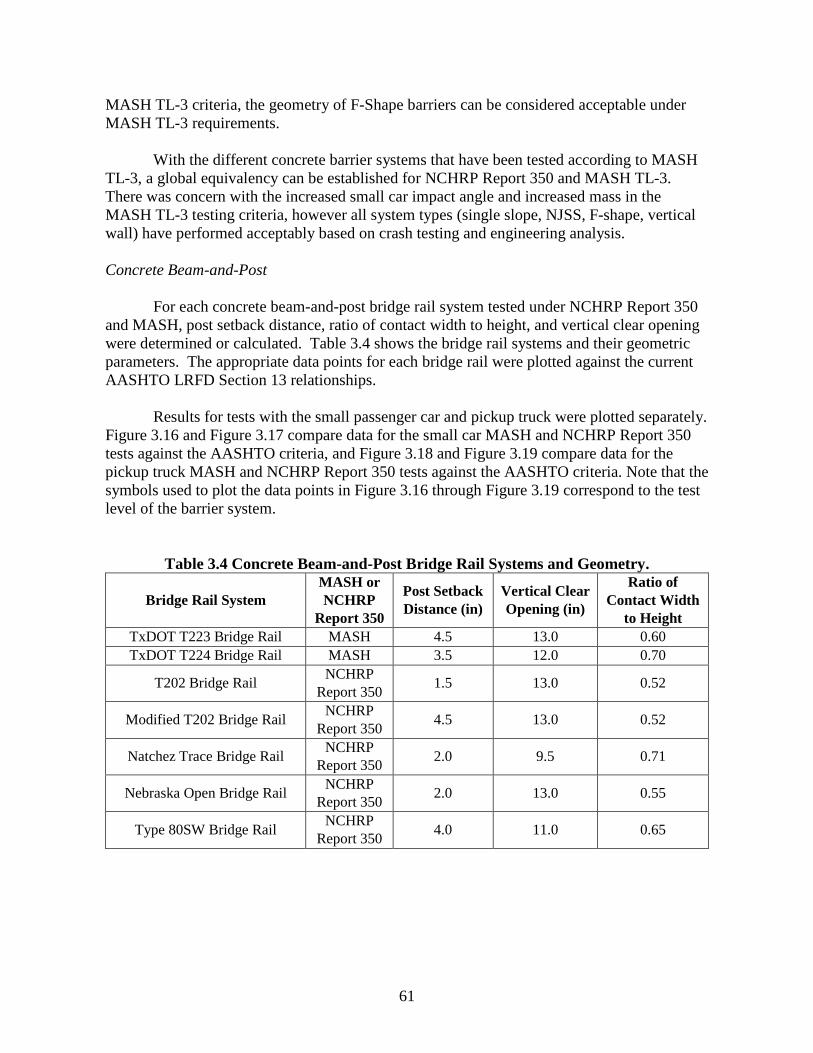
61
MASH TL-3 criteria, the geometry of F-Shape barriers can be considered acceptable under MASH TL-3 requirements. With the different concrete barrier systems that have been tested according to MASH TL-3, a global equivalency can be established for NCHRP Report 350 and MASH TL-3. There was concern with the increased small car impact angle and increased mass in the MASH TL-3 testing criteria, however all system types (single slope, NJSS, F-shape, vertical wall) have performed acceptably based on crash testing and engineering analysis. Concrete Beam-and-Post For each concrete beam-and-post bridge rail system tested under NCHRP Report 350 and MASH, post setback distance, ratio of contact width to height, and vertical clear opening were determined or calculated. Table 3.4 shows the bridge rail systems and their geometric parameters. The appropriate data points for each bridge rail were plotted against the current AASHTO LRFD Section 13 relationships. Results for tests with the small passenger car and pickup truck were plotted separately. Figure 3.16 and Figure 3.17 compare data for the small car MASH and NCHRP Report 350 tests against the AASHTO criteria, and Figure 3.18 and Figure 3.19 compare data for the pickup truck MASH and NCHRP Report 350 tests against the AASHTO criteria. Note that the symbols used to plot the data points in Figure 3.16 through Figure 3.19 correspond to the test level of the barrier system.
Table 3.4 Concrete Beam-and-Post Bridge Rail Systems and Geometry.
Bridge Rail System MASH or NCHRP
Report 350
Post Setback Distance (in)
Vertical Clear Opening (in)
Ratio of Contact Width
to Height TxDOT T223 Bridge Rail MASH 4.5 13.0 0.60 TxDOT T224 Bridge Rail MASH 3.5 12.0 0.70
T202 Bridge Rail NCHRP Report 350 1.5 13.0 0.52
Modified T202 Bridge Rail NCHRP Report 350 4.5 13.0 0.52
Natchez Trace Bridge Rail NCHRP Report 350 2.0 9.5 0.71
Nebraska Open Bridge Rail NCHRP Report 350 2.0 13.0 0.55
Type 80SW Bridge Rail NCHRP Report 350 4.0 11.0 0.65

62
Figure 3.16 MASH and NCHRP Report 350 Small Car Test Data – Post Setback versus Ratio of Rail Contact Width to Height.
Figure 3.17 MASH and NCHRP Report 350 Small Car Test Data – Post Setback Distance versus Vertical Clear Opening.
0
0.1
0.2
0.3
0.4
0.5
0.6
0.7
0.8
0.9
0 2 4 6 8 10 12
Rat
io o
f Rai
l Con
tact
Wid
th to
Hei
ght
Post Setback Distance (in)
350 TL-3
350 TL-4
MASH TL-5
350 Failed Test
0
2
4
6
8
10
12
14
16
0 2 4 6 8 10 12 14
Ver
tical
Cle
ar O
peni
ng (i
n)
Post Setback Distance (in)
350 TL-3
350 TL_4
MASH TL-5
350 Failed Test
High Potential
Low Potential
Preferred
Not Recommended
T202
T202

63
Figure 3.18 MASH and NCHRP Report 350 Pickup Truck Test Data – Post Setback versus Ratio of Rail Contact Width to Height.
Figure 3.19 MASH and NCHRP Report 350 Pickup Truck Test Data – Post Setback versus Vertical Clear Opening.
0
0.1
0.2
0.3
0.4
0.5
0.6
0.7
0.8
0.9
0 2 4 6 8 10 12
Rat
io o
f Rai
l Con
tact
Wid
th to
Hei
ght
Post Setback Distance (in)
350 TL-3
MASH TL-3
350 TL-4
MASH TL-5
Preferred
Not Recommended
0
2
4
6
8
10
12
14
16
0 2 4 6 8 10 12 14
Ver
tical
Cle
ar O
peni
ng (i
n)
Post Setback Distance (in)
350 TL-3
MASH TL-3
350 TL_4
MASH TL-5
High Potential
Low Potential

64
Only one concrete beam-and-post barrier system is known to have a failed crash test. This system was tested under NCHRP Report 350 Test 3-10. As can be seen in Figure 3.16 the system plots in the not recommended region of post setback criteria and is on the edge of the high snag potential region. In the NCHRP Report 350 crash Test 3-10 reported in, “Tests 4, 5, & 6: NCHRP Report 350 Testing of the Texas Type T202 Bridge Rail,” the small car was successfully redirected and contained. However, considerable damage to the vehicle occurred and maximum occupant compartment deformation was 10.8 inches in the left firewall area. This resulted in a failed test according to NCHRP Report 350 criteria. The same system was tested with an increased post setback distance of 4.5 inches, and the results were considered acceptable for NCHRP Report 350 Tests 3-10 and 3-11. In Test 3-10 on the modified system, the damage to the vehicle was significantly less compared to the previous test, and maximum occupant compartment deformation was 2 only inches. Figure 3.20 compares the damage between the two NCHRP Report 350 3-10 tests.
(a) NCHRP Report 350 Test 3-10 with 1.5-inch post setback(15)
(b) NCHRP Report 350 Test 3-10 with 4.5-inch post setback(15)
Figure 3.20 Comparison of Damage to NCHRP Report 350 3-10 Small Car for T202 Bridge Rail.
While the AASHTO geometric relationship criteria for post setback, vertical clear opening, and ratio of contact width to height appear appropriate for NCHRP Report 350 concrete beam-and-post systems, it is not as apparent for MASH concrete beam-and-post systems. There is very limited data to date on concrete beam-and-post systems that have been tested according to MASH. In fact, only one concrete beam-and-post system, the TxDOT T224 Bridge Rail, has been tested with the MASH small car vehicle. In addition, this concrete beam-and-post system was not a true concrete beam-and-post system due to the presence of a curb that helps prevent snagging of the vehicle on the posts. Figure 3.21 compares the T224 bridge rail against a more common concrete beam-and post system, the Nebraska Open Bridge Rail. As can be seen, the Nebraska Open Bridge Rail has a larger vertical clear opening at the bottom of the system, which is more critical in regard to snagging potential of the vehicle tire and wheel.
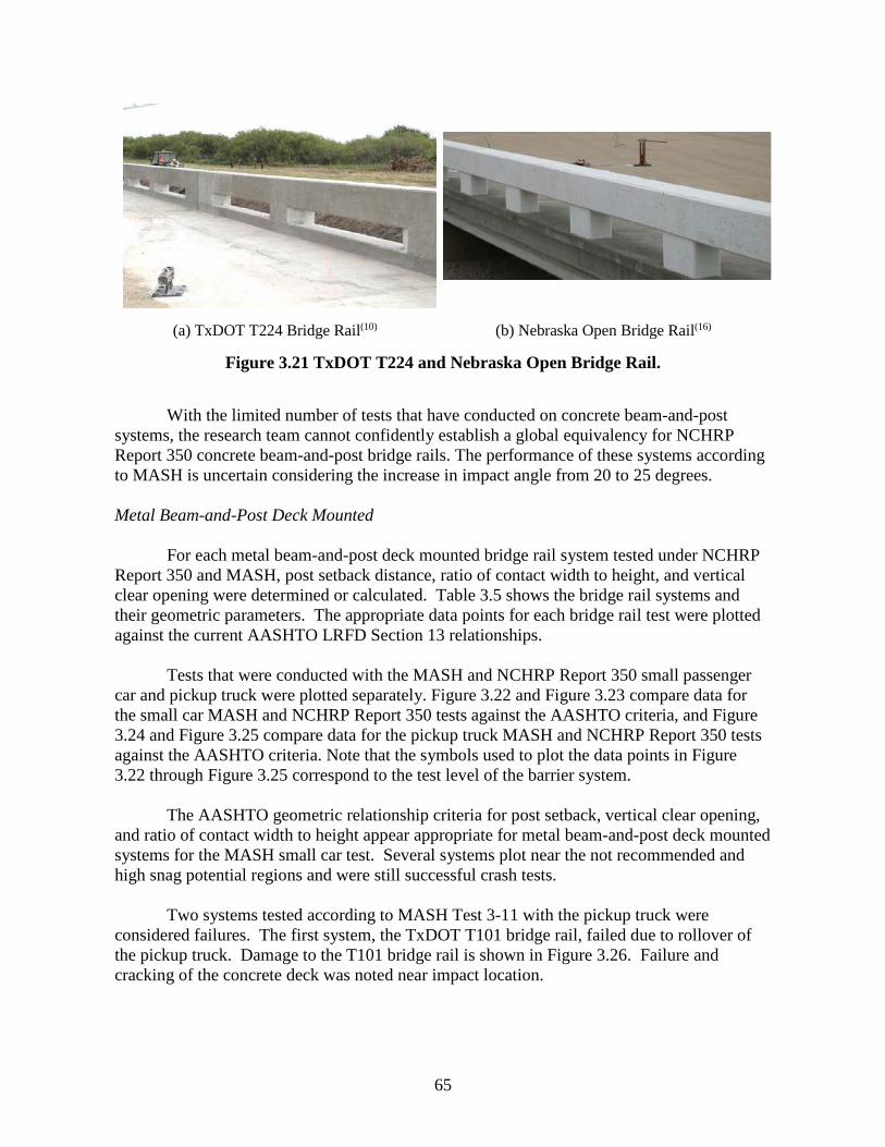
65
(a) TxDOT T224 Bridge Rail(10) (b) Nebraska Open Bridge Rail(16)
Figure 3.21 TxDOT T224 and Nebraska Open Bridge Rail.
With the limited number of tests that have conducted on concrete beam-and-post systems, the research team cannot confidently establish a global equivalency for NCHRP Report 350 concrete beam-and-post bridge rails. The performance of these systems according to MASH is uncertain considering the increase in impact angle from 20 to 25 degrees. Metal Beam-and-Post Deck Mounted For each metal beam-and-post deck mounted bridge rail system tested under NCHRP Report 350 and MASH, post setback distance, ratio of contact width to height, and vertical clear opening were determined or calculated. Table 3.5 shows the bridge rail systems and their geometric parameters. The appropriate data points for each bridge rail test were plotted against the current AASHTO LRFD Section 13 relationships. Tests that were conducted with the MASH and NCHRP Report 350 small passenger car and pickup truck were plotted separately. Figure 3.22 and Figure 3.23 compare data for the small car MASH and NCHRP Report 350 tests against the AASHTO criteria, and Figure 3.24 and Figure 3.25 compare data for the pickup truck MASH and NCHRP Report 350 tests against the AASHTO criteria. Note that the symbols used to plot the data points in Figure 3.22 through Figure 3.25 correspond to the test level of the barrier system.
The AASHTO geometric relationship criteria for post setback, vertical clear opening, and ratio of contact width to height appear appropriate for metal beam-and-post deck mounted systems for the MASH small car test. Several systems plot near the not recommended and high snag potential regions and were still successful crash tests. Two systems tested according to MASH Test 3-11 with the pickup truck were considered failures. The first system, the TxDOT T101 bridge rail, failed due to rollover of the pickup truck. Damage to the T101 bridge rail is shown in Figure 3.26. Failure and cracking of the concrete deck was noted near impact location.

66
Table 3.5 Metal Beam-and-Post Deck Mounted Bridge Rail Systems and Geometry.
Bridge Rail System MASH or NCHRP
Report 350
Post Setback Distance (in)
Vertical Clear Opening (in)
Ratio of Contact Width
to Height TxDOT 131 Bridge Rail MASH 4.0 11.0 0.42
TBTA Bridge Rail MASH 5.0 6.0 0.43 T101 Bridge Rail MASH 6.25 14.75 0.45
California St-70 Side Mounted Bridge Rail MASH 6.0 0.43 8.5
New York (2-member) Bridge Rail
NCHRP Report 350 6.0 13.0 0.38
New York (4-member) Bridge Rail
NCHRP Report 350 6.0 6.0 0.43
Mass. Type S3 Bridge Rail NCHRP Report 350 5.0 11.2 0.36
Illinois Side Mount Bridge Rail NCHRP Report 350 4.0 12.0 0.44
Tacoma Narrows Bridge Rail NCHRP Report 350 10.5 12.0 0.56
NETC Bridge Rail NCHRP Report 350 4.0 8.0 0.48
Figure 3.22 MASH and NCHRP Report 350 Small Car Test Data – Post Setback versus Ratio of Rail Contact Width to Height.
0
0.1
0.2
0.3
0.4
0.5
0.6
0.7
0.8
0.9
0 2 4 6 8 10 12
Rat
io o
f Rai
l Con
tact
Wid
th to
Hei
ght
Post Setback Distance (in)
MASH TL-3
350 TL-4
MASH TL-4
MASH TL-5
Preferred
Not Recommended

67
Figure 3.23 MASH and NCHRP Report 350 Small Car Test Data – Post Setback versus Vertical Clear Opening.
Figure 3.24 MASH and NCHRP Report 350 Pickup Truck Test Data – Post Setback versus Ratio of Rail Contact Width to Height.
0
2
4
6
8
10
12
14
16
0 2 4 6 8 10 12 14
Ver
tical
Cle
ar O
peni
ng (i
n)
Post Setback Distance (in)
MASH TL-3
350 TL-4
MASH TL-4
MASH TL-5
High Potential
Low Potential
0
0.1
0.2
0.3
0.4
0.5
0.6
0.7
0.8
0.9
0 2 4 6 8 10 12
Rat
io o
f Rai
l Con
tact
Wid
th to
Hei
ght
Post Setback Distance (in)
350 TL-4
MASH TL-4
MASH TL-5
350 Failed Test
MASH Failed Tests
Preferred
Not Recommended
T131
T101
NY Bridge Rail (2-member)

68
Figure 3.25 MASH and NCHRP Report 350 Pickup Truck Test Data – Post Setback versus Vertical Clear Opening.
Figure 3.26 Damage to TxDOT T101 Bridge Rail(17).
0
2
4
6
8
10
12
14
16
0 2 4 6 8 10 12 14
Ver
tical
Cle
ar O
peni
ng (i
n)
Post Setback Distance (in)
350 TL-4
MASH TL-4
MASH TL-5
350 Failed Test
MASH Failed Tests
High Potential
Low Potential
NY Bridge Rail (2-member)
T101
T131

69
The second bridge rail system, the TxDOT T131 bridge rail, also failed due to rollover of the pickup truck. Damage to the T131 bridge rail is shown in Figure 3.27. Similar failure and cracking of the concrete deck was noted at the posts in the impact region.
Figure 3.27 Damage to TxDOT T131 Bridge Rail(18).
In both tests, impact loads imparted to the steel posts resulted in punching shear failure of the reinforced concrete bridge deck. It was concluded that the deck failure resulted in rotation of the posts that subsequently lead to instability of the impacting vehicle. Metal Beam-and-Post Curb Mounted For each metal beam-and-post curb mounted bridge rail system tested under NCHRP Report 350 and MASH, post setback distance, ratio of contact width to height, and vertical clear opening were determined or calculated. Table 3.6 shows the bridge rail systems and their geometric parameters. The appropriate data points for each bridge rail test were plotted against the current AASHTO LRFD Section 13 relationships. Tests that were conducted with the MASH and NCHRP Report 350 small passenger car and pickup truck were plotted separately. Figure 3.28 and Figure 3.29 compare data for the small car MASH and NCHRP Report 350 tests against the AASHTO criteria, and Figure 3.30 and Figure 3.31 compare data for the pickup truck MASH and NCHRP Report 350 tests against the AASHTO criteria. Note that the symbols used to plot the data points in Figure 3.28 through Figure 3.31 correspond to the test level of the barrier system.
The AASHTO geometric relationship criteria for post setback, vertical clear opening, and ratio of contact width to height appear reasonable for metal beam-and-post curb mounted systems for the MASH small car test. Several systems plot near the not recommended and high snag potential regions and were still successful crash tests. Although few data points were located near the high snag potential region, the presence of the curb aids in preventing wheel snag with the post.
However, a test conducted by Caltrans on their ST-10 bridge rail resulted in a failed
test due to rollover of the pickup truck.(11) No significant damage to the barrier or vehicle was

70
noted. The maximum permanent deflection of the bridge rail was only 0.4 inches. Dynamic deflection was not reported due to issues with the sensors. Figure 3.32 shows the damage to the rail and the pickup truck after impact with the rail. The reason for the failure has not been identified. With this failed crash test and limited number of MASH crash test data points plotting near the edge of the acceptable zone of the geometric guidelines, the research team is not confident in confirming geometric relationship criteria for MASH metal beam-and-post curb mounted bridge rails.
Table 3.6 Metal Beam-and-Post Curb Mounted Bridge Rail Systems and Geometry.
Bridge Rail System MASH or NCHRP
Report 350
Post Setback Distance (in)
Vertical Clear Opening (in)
Ratio of Contact Width
to Height TxDOT 131RC Bridge Rail MASH 6.0 7.0 0.64
Rist Bridge Rail MASH 7.87 13.0 0.47 TxDOT Picket Rail MASH 6.38 8.0 0.49
Dong-A Steel Bridge Rail MASH 7.87 11.8 0.45 ST-10 Bridge Rail MASH 5.50 10.0 0.42
TxDOT Type C2P Bridge Rail MASH 6.38 10.5 0.42 T1F Bridge Rail MASH 6.88 10.5 0.55
Mass. Type S3 Bridge Rail NCHRP Report 350 5.0 8.0 0.54
George Washington Memorial Parkway Bridge Rail
NCHRP Report 350 2.8 8.25 0.54
T77 Bridge Rail NCHRP Report 350 4.0 7.7 0.57
Alaska Bridge Rail NCHRP Report 350 5.0 9.0 0.53
Oregon Bridge Rail NCHRP Report 350 7.0 5.75 0.6
Wyoming 830WYBRAIL Bridge Rail
NCHRP Report 350 3.5 10.4 0.4
NETC Bridge Rail NCHRP Report 350 4.0 8.0 0.62
Illinois 2399-1 Bridge Rail NCHRP Report 350 4.0 7.0 0.59
ST-20 Bridge Rail NCHRP Report 350 3.5 8.3 0.43

71
Figure 3.28 MASH and NCHRP Report 350 Small Car Test Data – Post Setback versus Ratio of Rail Contact Width to Height.
Figure 3.29 MASH and NCHRP Report 350 Small Car Test Data – Post Setback versus Vertical Clear Opening.
0
0.1
0.2
0.3
0.4
0.5
0.6
0.7
0.8
0.9
0 2 4 6 8 10 12
Rat
io o
f Rai
l Con
tact
Wid
th to
Hei
ght
Post Setback Distance (in)
350 TL-3
MASH TL-3
350 TL-4
MASH TL-4
Preferred
Not Recommended
0
2
4
6
8
10
12
14
16
0 2 4 6 8 10 12 14
Ver
tical
Cle
ar O
peni
ng (i
n)
Post Setback Distance (in)
350 TL-3
MASH TL-3
350 TL-4
MASH TL-4
High Potential
Low Potential

72
Figure 3.30 MASH and NCHRP Report 350 Pickup Truck Test Data – Post Setback versus Ratio of Rail Contact Width to Height.
Figure 3.31 MASH and NCHRP Report 350 Pickup Truck Test Data – Post Setback
versus Vertical Clear Opening.
0
0.1
0.2
0.3
0.4
0.5
0.6
0.7
0.8
0.9
0 2 4 6 8 10 12
Rat
io o
f Rai
l Con
tact
Wid
th to
Hei
ght
Post Setback Distance (in)
350 TL-3
MASH TL-3
350 TL-4
MASH TL-4
350 Failed Tests
MASH Failed Test
Preferred
Not Recommended
0
2
4
6
8
10
12
14
16
0 2 4 6 8 10 12 14
Ver
tical
Cle
ar O
peni
ng (i
n)
Post Setback Distance (in)
350 TL-3
MASH TL-3
350 TL-4
MASH TL-4
350 Failed Tests
MASH Failed Test
High Potential
Low Potential
ST-10
ST-10
T-77
T-77

73
Figure 3.32 Damage to Barrier and Vehicle for ST-10 Bridge Rail(19).
Metal Beam-and-Post on Concrete Parapet For each metal beam-and-post on concrete parapet bridge rail system tested under NCHRP Report 350 and MASH, post setback distance, ratio of contact width to height, and vertical clear opening were determined or calculated. Table 3.7 shows the bridge rail systems and their geometric parameters. The appropriate data points for each bridge rail test were plotted against the current AASHTO LRFD Section 13 relationships. Tests that were conducted with the MASH and NCHRP Report 350 small passenger car and pickup truck were plotted separately. Figure 3.33 and Figure 3.34 compare data for the small car MASH and NCHRP Report 350 tests against the AASHTO criteria, and Figure 3.35 and Figure 3.36 compare data for the pickup truck MASH and NCHRP Report 350 tests against the AASHTO criteria. Note that the symbols used to plot the data points in Figure 3.33 through Figure 3.36 correspond to the test level of the barrier system.
The AASHTO geometric relationship criteria for post setback, vertical clear opening, and ratio of contact width to height appear appropriate for NCHRP Report 350 and MASH metal beam-and-post parapet mounted systems. For the small car and pickup truck NCHRP Report 350 and MASH test data, several systems plot near the edge of the recommended region and were still successful crash tests.
In terms of the relationship for snag potential, there are no MASH metal beam-and-post parapet mounted systems that plot near the high snagging potential region. However, for a sufficiently tall concrete parapet, there is little concern for wheel and bumper snagging.
Metal beam-and-post parapet mounted bridge rail systems commonly have concrete
parapets that are at least 18 inches tall. This can aid in preventing snagging for small cars and even pickup trucks. Typical MASH pickup trucks have a height to the top of bumper that ranges from 25 to 27 inches, and top of a passenger car bumper is typically around 21 inches.

74
Table 3.7 Metal Rail on Concrete Parapet Bridge Rail Systems and Geometry.
Bridge Rail System MASH or NCHRP
Report 350
Post Setback Distance (in)
Vertical Clear Opening (in)
Ratio of Contact Width
to Height Lake Pontchartrain Bridge Rail MASH 2.75 8.0 0.48 Lake Pontchartrain Bridge Rail
Option 2 MASH 4.5 8.0 0.44
Type T4(A) Bridge Rail NCHRP Report 350 8.0 6.9 0.68
BR27C Bridge Rail NCHRP Report 350 3.0 14.0 0.67
Type 90 Bridge Rail NCHRP Report 350 7.0 10.75 0.7
Figure 3.33 MASH and NCHRP Report 350 Small Car Test Data – Post Setback versus Ratio of Rail Contact Width to Height.
0
0.1
0.2
0.3
0.4
0.5
0.6
0.7
0.8
0.9
0 2 4 6 8 10 12
Rat
io o
f Rai
l Con
tact
Wid
th to
Hei
ght
Post Setback Distance (in)
350 TL-4
MASH TL-4
Preferred
Not Recommended

75
Figure 3.34 MASH and NCHRP Report 350 Small Car Test Data – Post Setback versus
Vertical Clear Opening.
Figure 3.35 MASH and NCHRP Report 350 Pickup Truck Test Data – Post Setback versus Ratio of Rail Contact Width to Height.
0
2
4
6
8
10
12
14
16
0 2 4 6 8 10 12 14
Ver
tical
Cle
ar O
peni
ng (i
n)
Post Setback Distance (in)
350 TL-4
MASH TL-4
High Potential
Low Potential
0
0.1
0.2
0.3
0.4
0.5
0.6
0.7
0.8
0.9
0 2 4 6 8 10 12
Rat
io o
f Rai
l Con
tact
Wid
th to
Hei
ght
Post Setback Distance (in)
350 TL-3
350 TL-4
MASH TL-4
Preferred
Not Recommended

76
Figure 3.36 MASH and NCHRP Report 350 Pickup Truck Test Data – Post Setback
versus Vertical Clear Opening. Although the data is somewhat limited, the researchers have recommended a global equivalency between NCHRP Report 350 and MASH TL-2 and TL-3 can be established for metal beam-and-post parapet mounted systems with a concrete parapet height greater than or equal to 24 inches. Considering that the MASH pickup truck vehicle top of bumper height ranges from 25 to 27 inches, a parapet height of 24 inches or greater will mitigate snagging of the test vehicles. Future testing could justify an equivalency of concrete parapets with heights less than 24 inches. One particular system, the Texas Type T4(A) bridge rail, has a parapet height of 18 inches. If this or a similar system is successfully tested, it could potentially allow for the range of parapet heights for global equivalency to be expanded. 3.2 Test Level 4 (TL-4) Bridge Rail Systems 3.2.1 Stability Requirements Test 4-12 is the structural adequacy test for Test Level 4 (TL-4). Under NCHRP Report 350, Test 4-12 involved a 17,640-lb single unit truck (SUT) impacting the barrier at a nominal speed of 50 mi/h and an angle of 15 degrees. The center of mass of the ballast was required to be at a nominal height of 67 inches. Under MASH, the impact conditions associated with test 4-12 were significantly modified. The weight of the single unit truck design vehicle was increased from 17,640 lb to 22,050 lb. Impact speed was increased from 50 mph to 56 mph, and the nominal CG height of the vehicle ballast was reduced 4 inches to 63 inches. Due to the increase in vehicle weight and impact velocity, the nominal impact severity of MASH test 4-12 increased by approximately 56% compared to NCHRP Report 350 (Table 3.8). This represents a significant increase in the amount of lateral energy imparted to the barrier, which is an indication that lateral design impact loads have also increased under MASH.
0
2
4
6
8
10
12
14
16
0 2 4 6 8 10 12 14
Ver
tical
Cle
ar O
peni
ng (i
n)
Post Setback Distance (in)
350 TL-3
350 TL-4
MASH TL-4
High Potential
Low Potential

77
Table 3.8 Impact Severity for MASH Test 4-12.
Test Level
Test Vehicle
Vehicle Weight (lbs)
Impact Speed, V (mi/h)
Impact Angle, θ (degrees)
Impact Severity, IS (k-
ft) Percent Change
(%) 350 MASH 350 MASH 350 MASH 350 MASH
4 SUV 17600 22000 50 56 15 15 98.5 154.4 56.8
The AASHTO LRFD Bridge Design Specifications recommended a minimum rail height of 32 inches for TL-4 railings designed to meet NCHRP Report 350 guidelines. Numerous bridge rail systems have been successfully crash tested under NCHRP Report 350 TL-4 impact conditions with a 32 inch rail height. However, testing performed at MwRSF under NCHRP Project 22-14(02) (8) and at TTI under NCHRP Project 22-14(03) (9)
demonstrated that this height was not adequate for MASH TL-4 impact conditions. In these tests, which differed only by the C.G. height of the ballast inside the single unit truck (SUT) design test vehicle, the SUT rolled over the top of a 32-inch tall New Jersey safety shape barrier. Under TxDOT Research Project 9-1002 ‟Roadside Safety Device Crash Testing Program,” TTI researchers investigated the minimum rail height requirement and lateral design load for MASH TL-4 bridge rails.(6) The researchers employed finite element analysis and crash testing to determine the minimum rail height for MASH TL-4 impact conditions. The minimum rail height for MASH TL-4 barriers was determined to be 36 inches. This was verified with a MASH TL-4 test of a 36-inch tall single slope barrier. 3.2.2 Strength Requirements Under the same TxDOT research project (6), researchers used impact simulations to calculate lateral impact loads for MASH TL-4 impact conditions for a rigid single slope barrier with various heights. Results indicated that the lateral loads for MASH TL-4 were significantly greater than those specified for NCHRP Report 350 TL-4 impact conditions. Further, the lateral impact force was found to vary with rail height. For a 36-inch tall barrier, the design impact load was determined to be approximately 68 kips. As the height of the barrier increases, more of the cargo box of the single unit truck is engaged and the lateral load on the barrier increases. For a barrier height of 42 inches, the lateral design impact load increases to approximately 80 kips. The 36-inch single slope bridge rail that was tested had a calculated capacity of approximately 70 kips. The continuous concrete rail performed well without any significant damage to the rail or deck. This effort to define design impact loads for MASH TL-4 was reproduced and expanded under NCHRP Project 22-20(02) “Design Guidelines for TL-3 through TL-5 Roadside Barrier Systems Placed on Mechanically Stabilized Earth (MSE) Retaining Walls.” Researchers used finite element impact simulations to determine the magnitude and

78
distribution of impact loads imparted by the SUT based on MASH TL-4 impact conditions. It was found that the magnitude, distribution and resultant height of the impact load are influenced by the height of the barrier. Design impact loads in the lateral, longitudinal, and vertical direction, and the longitudinal distribution and height of the resultant lateral load were recommended for MASH TL-4 impacts. A summary of the magnitude, distribution and resultant height of the MASH TL-4 impact loads for different barrier heights is presented in Table 3.9. It is noted that the transverse force, Ft, increases as the barrier height increases. As the height of the barrier increases, there is less vehicle roll and more mass is engaged in the impact, thereby increasing the impact load.
Table 3.9 Summary of Magnitude, Distribution and Application of the MASH TL-4 Impact Loads.
As presented in Table 3.9, the magnitude of the impact force for MASH TL-4 bridge rails has increased compared to the current design recommendation of 54 kips for NCHRP Report 350 TL-4 rails contained in Section 13 of the AASHTO LRFD Bridge Design Specification. However, the resultant load height must also be considered when evaluating required capacity. Current guidance for NCHRP Report 350 TL-4 bridge rails recommends that the design load be placed at a height of 32 inches. This height corresponds to the top of barrier for the minimum recommended rail height. Thus, the moment that must be resisted by the barrier is 1,728 kip-inches (54 kips x 32 inches). Comparatively, with reference to Table 3.9, the moment corresponding to a 36-inch tall MASH TL-4 bridge rail is 67.2 kips x 25.1 inches = 1,687 kip-inches, which is less than the current design moment used for NCHRP Report 350 bridge rails.. Thus, at the minimum recommended height of 36-inches, MASH TL-4 bridge rails will not require additional capacity compared to current NCHRP Report 350 design recommendations. 3.2.3 Geometric Requirements Specific geometric requirements for the MASH TL-4 SUT have not been established. The geometric criteria previously presented for TL-3 would also apply to TL-4 bridge rails. The test matrix for a MASH TL-4 rail includes Test 4-10 with the 1100C small passenger car and Test 4-11 with the 2270 pickup truck.

79
It was previously discussed that the recommended minimum rail height to achieve MASH TL-4 impact performance is 36 inches. It is likely that some TL-4 bridge rails will be designed with a height greater than 36 inches to provide improved stability for heavy truck impacts and to accommodate future pavement overlays. Although not a specific MASH evaluation criterion, consideration should be given to the potential for occupant head excursion and contact with components of the bridge rail system for these taller height barriers. However, testing to date has not found this to be a problem with existing rails. 3.3 Test Level 5 (TL-5) Bridge Rail Systems The impact conditions associated with MASH Test 5-12 with the 36000V tractor-van trailer have not changed from NCHRP Report 350 to MASH. Therefore, extensive evaluation of NCHRP Report 350 TL-5 bridge rails is not required. 3.3.1 Stability Requirements The vehicle mass, impact speed and impact angle has not changed from NCHRP Report 350 TL-5 to MASH TL-5. Therefore the impact severity has not changed for MASH TL-5. The minimum rail height for MASH TL-5 impacts remains 42 inches. There are several 42-inch barriers that have met NCHRP Report 350 and MASH TL-5 requirements.
Recently, TTI researchers designed and successfully tested a new MASH TL-5 bridge rail for TxDOT.(10) This new barrier, which is known as the T224, was designed with openings to provide some aesthetic characteristics. It is believed to be the first TL-5 bridge rail to incorporate openings into the rail design. Additionally, the system was tested on an 8 ½-inch thick concrete deck cantilever, which is thinner than decks previously designed for TL-5 rails. A photo of the TxDOT T224 MASH TL-5 bridge rail is shown in Figure 3.37. The TxDOT T224 met all the strength and performance requirements of MASH TL-5 when tested with a 36000V tractor-van trailer with the new 53-ft long trailer now permitted under MASH 2016. 3.3.2 Strength Requirements As part of NCHRP Project 22-20(02), finite element analyses were also conducted to determine impact loads associated with the MASH 80,000-lb tractor-van trailer vehicle for different barrier heights under TL-5 impact conditions. The barrier heights analyzed were selected to cover the range of heights of previously crash tested TL-5 barriers. A tall rigid wall provided information regarding the maximum impact load associated with a TL-5 impact. The simulation data was used to determine the dynamic load in the lateral, longitudinal and vertical direction. The distribution of the lateral impact load in the longitudinal and vertical directions of the barrier was also investigated. Barrier height was found to have a dramatic effect on the peak lateral load. Above a height of 42 inches, the trailer floor engaged the barrier, resulting in a significant increase in force applied to the barrier.

80
Figure 3.37 TxDOT T224 MASH TL-5 Bridge Rail System(10). As shown in Table 3.10, the dynamic load due to the first impact with the front of the tractor is similar for all barrier heights. The longitudinal force, FL, which is controlled by the frictional contact between the tires and the barrier, is also similar in all cases. Similar to the TL-4 study, the vertical force Fv decreases as barrier height increases. This is due to reduction in roll of the tractor-trailer. The peak lateral loads associated with the taller barriers were greater than the load measured in the instrumented wall tests conducted in the 1980’s. The primary reason for this is the difference in the ballast. Many of the early tests conducted with tractor-van-trailers used sand bags and hay bales for ballast. Because the ballast was not rigidly secured to the floor of the trailer, it was able to shift during impact resulting in lower forces on the barrier. While these are still considered an acceptable type of ballast, MASH states that “Ballast should be firmly secured to prevent movement during and after the test.” This results in higher impact loads transmitted to the barrier.
Although the results of this project indicate a potential need to update the TL-5 design impact loads contained in Section 13 of the AASHTO LRFD Bridge Design Specification, it is not necessarily material to the evaluation of TL-5 bridge rails under this project. As discussed, the impact conditions and, hence, impact severity have not changed for MASH TL-5. Therefore, if a TL-5 bridge rail was successfully crash tested in accordance with NCHRP Report 350 and the ballast inside the trailer was properly restrained, the barrier should have sufficient capacity for MASH TL-5 and no further strength analyses will be needed. If the ballast was not rigidly secured, strength analysis may be required to confirm the structural adequacy of the barrier. If the rail is determined to have sufficient structural capacity, it could be considered MASH TL-5 compliant without further testing.

81
Table 3.10 Summary of Magnitudes, Distributions and Resultant Height of Loads for MASH TL-5 Impact.
3.3.3 Geometric Requirements Specific geometric requirements for the MASH TL-5 tractor-van trailer have not been established. The geometric criteria previously presented for TL-3 would also apply to TL-5 bridge rails. The test matrix for a MASH TL-5 rail includes Test 5-10 with the 1100C small passenger car and Test 5-11 with the 2270 pickup truck. As discussed in regard to MASH TL-4, consideration should be given to the potential for occupant head excursion and contact with components of the bridge rail system for these tall TL-5 barriers. Testing of 42-inch TL-5 barriers to date has not indicated a problem in this regard. 3.4 Summary of Evaluation Requirements for Test Levels 3, 4, and 5 The conclusions for each of the different test level requirements are summarized in the list below.
• The static stability of the MASH 2270P pickup truck is similar or slightly improved compared to the NCHRP Report 350 2000P pickup truck. Anecdotal crash test experience supports improved stability of the MASH 2270P pickup truck. Crash test comparisons of two similar rails were inconclusive regarding relative stability of the two vehicles. To assist in evaluating vehicle stability, finite element simulations were performed with the MASH pickup truck vehicle impacting a rigid wall at varying barrier heights of 27, 28, and 29 inches. Based on the results from the simulations, the minimum recommended rail height for MASH TL-3 bridge rails is 29 inches. This minimum rail height is higher than the minimum rail height of 27 inches for NCHRP

82
Report 350 bridge rails. Bridge rails successfully tested under NCHRP Report 350 TL-3 impact conditions should generally be adequate for the equivalent TL-3 under MASH. (Section 3.1.1)
• MASH Test 11 with the 2270P pickup truck has a higher impact severity and greater impact load compared to NCHRP Report 350 Test 11 with the 2000P truck for both TL-2 and TL-3. Consequently, TL-2 and TL-3 bridge rail systems will require additional capacity. However, current estimates of impact load and resultant height indicate that NCHRP Report 350 TL-3 bridge rails may have significant reserve capacity. This reserve capacity appears to be sufficient to accommodate the increased capacity demand associated with MASH impact conditions. (Section 3.1.2)
• Initial assessment of the impact performance of beam-and-post bridge rail systems under MASH guidelines indicates that the current geometric relationships for bridge rail design contained in Section 13 of the AASHTO LRFD Bridge Design Specifications still has some validity for both the small passenger car and pickup truck, and that bridge rail systems designed to meet these geometric relationships under NCHRP Report 350 may satisfy MASH. Given the significant increase in impact severity of MASH Test 10 with the 1100C small passenger car design test vehicle due to increases in both vehicle weight and impact angle, this finding may be very important to establishing test level equivalencies. It is noted that this conclusion is based on a limited amount of data and tests conducted according to MASH. As more data becomes available, the geometric data should continue to be updated and analyzed. (Section 3.1.3)
• A global equivalency can be confidently established for metal beam-and-post parapet mounted systems that have a concrete parapet height greater than or equal to 24 inches. The parapet height requirement was selected to mitigate potential wheel and bumper snagging with MASH small car and pickup truck vehicles. (Section 3.1.4)
• The recommended minimum rail height for a TL-4 bridge rail is 36 inches. (Section 3.2.1)
• MASH Test 4-12 with the SUT has a higher impact severity and greater impact load compared to NCHRP Report 350 Test 4-12. Consequently, MASH TL-4 bridge rail systems will require additional capacity. However, current estimates of impact load and resultant height indicate that NCHRP Report 350 TL-4 may have substantial reserve capacity. This reserve capacity appears to be sufficient to accommodate the increased capacity demand associated with MASH TL-4 impact conditions. This is primarily due to having improved estimates of load application heights using advanced finite element impact simulations. (Section 3.2.2)
• Geometric requirements for MASH TL-4 bridge rails are the same as for MASH TL-3 bridge rails with the exception of rail height, which will be a minimum of 36 inches. (Section 3.2.3)
• The minimum rail height for a MASH TL-5 bridge rails remains 42 inches. (Section 3.3.1)

83
• A bridge rail successfully crash tested in accordance with NCHRP Report 350 TL-5 with properly restrained ballast will have sufficient capacity for MASH TL-5. (Section 3.3.2)
• Geometric requirements for MASH TL-5 bridge rails are the same as for MASH TL-3 bridge rail. (Section 3.3.3)
3.5 Global Equivalency Results The resulting global equivalencies are presented in Table 3.11. All NCHRP Report 350 TL-5 bridge rail system types can be found acceptable under equivalent MASH TL-5. NCHRP Report 350 TL-3 and TL-4 bridge rail systems are dependent upon the bridge rail type. NCHRP Report 350 TL-3 and TL-4 solid concrete parapets and metal rails on concrete parapets with a parapet height greater than 24 inches are considered acceptable under MASH TL-3. NCHRP Report 350 TL-3 and TL-4 concrete post and beam, metal rail deck, or curb mounted systems can be found acceptable under MASH TL-2.
Table 3.11 Summary of Global Test Equivalency for NCHRP Report 350 Bridge Rail Systems.
NCHRP Report 350 Rail System
Type
MASH Test Level
TL-2 TL-3 TL-4 TL-5
Solid Concrete Parapet TL-2 TL-3
TL-4 TL-5
Concrete Beam-and-Post
TL-2 TL-3 TL-4
TL-5
Metal Beam-and-Post Deck Mounted
TL-2 TL-3 TL-4
TL-5
Metal Beam-and-Post on Curb
TL-2 TL-3 TL-4
TL-5
Metal Beam-and-Post on Concrete
Parapet* TL-2 TL-3
TL-4 TL-5
* Concrete parapet height greater than or equal to 24 inches


85
4 RAIL SPECIFIC ANALYSIS METHODOLOGY
Based on the global test level equivalency presented in Chapter 3, many of the NCHRP Report 350 bridge rail systems are not eligible to be grandfathered under MASH. These rail systems will require more detailed analyses and evaluation, and perhaps crash testing. This section describes the rail specific analyses methodologies applied to different bridge rail categories and the results of the analyses performed on the bridge rail systems prioritized in Chapter 2. The funding resources allocated for this project were not sufficient to perform a detailed strength analysis and impact performance evaluation of every bridge rail system identified. The analysis effort includes the evaluation of the most common, highest prioritized railing systems. The highest ranked rails in the highest ranked categories and test levels were analyzed based on the specific details and attributes of the rail system. The prioritization of commonly used bridge rail systems is described in Chapter 2, and is based on relative frequency of use among state DOTs that responded to the survey with consideration given to different rail categories, subcategories, test levels, and features. As discussed in Chapter 2, rails with similar characteristics and features were grouped together to more appropriately define frequency of use and, hence, priority for a given subcategory of rails. The selection of specific rail systems for analysis was based on the relative priority of the rails that were grouped to form that particular subcategory. For example, there may be 5 state DOTs that have a detail for a metal rail on concrete curb with two longitudinal rail elements. Because these rails have some key similar characteristics (e.g., metal and concrete material combination, curb mounted, two longitudinal rail elements), they were grouped together to establish the relative frequency of use and priority ranking for this subcategory. The first system selected for detailed rail-specific analysis in this particular subcategory would be the rail with the highest indicated frequency of use or ranking. Altogether twenty-two bridge rail systems were analyzed based on this selection method. To evaluate the prioritized bridge rail systems according to MASH, three different criterions were considered. These criteria consist of stability, rail geometrics, and strength. The analysis methodologies used to evaluate these criteria are presented below. The results of the analyses were used to determine which rails can be considered MASH compliant and which will require further analysis or crash testing to establish MASH compliance. 4.1 Stability Requirements for MASH Bridge Rail Systems For a bridge rail system to be considered a MASH acceptable barrier, a minimum height must be met to ensure stability of the vehicle. Table 4.1 shows the minimum height requirements for MASH TL-3, TL-4 and TL-5 bridge rail systems. The minimum height requirement for TL-3 was determined using finite element simulations as previously presented in Chapter 3. The TL-4 minimum rail height was determined to be 36 inches in a previous TTI study.(6) Minimum rail height for TL-5 remains 42 inches as previously specified for NCHRP Report 350 bridge rails.

86
Table 4.1 Minimum Height Requirements for MASH TL-3, TL-4, and TL-5.
MASH Test Level Minimum Height (in.)
TL-3 29
TL-4 36
TL-5 42
The height of a bridge rail system being analyzed was acquired from the detailed drawings of that specific bridge rail system and compared to the minimum height requirement for the specified test level. As specified in AASHTO Section 13 LRFD, rail height is measured to the top of the rail. If the minimum rail height was satisfied, the rail was considered to satisfactorily meet stability requirements. 4.2 Geometric Requirements for MASH Bridge Rail Systems The geometric relationships for bridge railings contained in Section 13 AASHTO LRFD Bridge Design Specifications (Figure 4.1) were applied to evaluate rail geometry. These relationships pertain to the potential for wheel, bumper or hood snagging on elements of the bridge rail system. Severe snagging can lead to a number of undesirable consequences including increased occupant compartment deformation, higher accelerations and occupant risk indices, and vehicle instability. For each bridge rail system analyzed, post setback distance, ratio of contact width to height, and vertical clear opening were determined or calculated from the provided bridge rail details and plotted against the current AASHTO LRFD Section 13 geometric criteria. When pedestrian hand rails are mounted on top of a traffic barrier in order to provide combined traffic and pedestrian use, the potential for vehicle interaction with the hand rail was evaluated. If available, previous testing of systems with similar geometry was analyzed to determine extent of intrusion of vehicle components beyond the traffic face of the rail. This zone of intrusion was then used to evaluate potential for vehicle contact with the pedestrian hand rail.

87
Figure 4.1 AASHTO Section 13 Figures A13.1.1-2 and A13.1.1-3.
4.3 Strength Requirements for MASH Bridge Rail Systems Section 13 of the AASHTO LRFD Bridge Design Specifications contains procedures for analyzing the structural capacity of different types of bridge railings (e.g., steel, concrete). Using these procedures, an analysis of the strength of the rail system was performed. For concrete parapet railings, the yield line method was applied to determine the ultimate strength of the system. Metal rail systems were analyzed using plastic strength analysis methods. The strength of the rail members, posts, and post connections were analyzed to obtain the overall strength of the rail system. To evaluate the strength of a beam-and-post bridge rail system, the post strength must be determined from various load cases. The load case that provides the least amount of post resistance is used in the analysis as the limiting post strength. Several common limiting load cases that are frequently used for analysis of a bridge rail system’s post strength include:
• Plastic strength of post. • Post strength based on tension/shear strength of bolts. • Post strength based on baseplate bearing on concrete from post baseplate. • Post strength based on lateral block shear in curb. • Post strength based on anchor bolt tension cone failure in concrete. • Post strength based on strength of reinforcing. • Post strength based on vertical punching shear in concrete from post baseplate.
The project team considered the limiting failure modes as determined from previous NCHRP Report 350 crash tests of the rail system and/or similar rail systems. The calculated strength of the bridge rail systems were compared to design impact loads (see Table 4.2) corresponding to relevant MASH Test Level. Complete structural details of the rail system were required for this task.
0
0.1
0.2
0.3
0.4
0.5
0.6
0.7
0.8
0.9
0 5 10 15
Rat
io o
f Rai
l Con
tact
Wid
th to
H
eigh
t
Post Setback Distance (in)
Preferred
Not Recommended
0
2
4
6
8
10
12
14
16
0 5 10 15
Ver
tical
Cle
ar O
peni
ng (i
n)
Post Setback Distance (in)
High Snag Potential
Low Snag Potential

88
Table 4.2 Design Impact Loads.
MASH Test Level
Rail Height (in.)
Design Impact Force (kip)
Height of Design Impact Force (in.)
TL-3 ≥ 29 71 19
TL-4 36 68(7) 25(7)
˃ 36 80(6) 30(7)
TL-5 42 160(7) 35(7)
˃ 42 262(7) 43(7)
For NCHRP Report 350 TL-3 impact conditions, a design load of 54 kips at a height of 24 inches has been used for strength design. Based on finite element impact simulations, the load that a MASH TL-3 barrier must resist is 71 kips at a height of 19 inches. A bridge rail system must be able to resist this impact force to be classified as a MASH TL-3 barrier without crash testing. The design moment associated with this load is within 4% of the current NCHRP Report 350 TL-3 design moment. Therefore, it is expected that existing NCHRP Report 350 TL-3 barriers will satisfy MASH TL-3 strength requirements. For NCHRP Report 350 TL-4 impact conditions, a design load of 54 kips at a height of 32 inches has been used. As discussed in Chapter 3, recent research has recommended a design impact load of 68 kips at a height of 25 inches for a 36-inch tall MASH TL-4 bridge rail or 80 kips at a height of 30 inches for a MASH TL-4 bridge rail taller than 36 inches. A bridge rail system must be able to resist this impact force to be classified as a MASH TL-4 barrier without crash testing. For a 36-inch tall MASH TL-4 bridge rail, the load conditions produce an equivalent design moment to that used in the design of NCHRP Report 350 bridge rails. Therefore, a 36-inch tall MASH TL-4 bridge rail will not require added capacity above NCHRP Report 350 TL-4 bridge rail requirements. It is noted that the design impact load increases with barrier height, so taller barriers are required to have additional capacity. If a TL-5 bridge rail was successfully crash tested in accordance with NCHRP Report 350, then the barrier should have sufficient capacity for MASH TL-5 and no further strength analyses are needed.
4.4 Rail Specific Analysis Methodology Four bridge rail system analysis categories were developed for this project to encompass the various bridge rail systems that were analyzed. The four bridge rail system analysis categories are Solid Concrete Parapet, Concrete Post and Beam, Steel Post and Beam, and Combination Steel Post and Concrete Parapet. Analysis templates for the four

89
different categories were created in Microsoft Excel to assist in determining the overall strength of the bridge rail systems. As previously discussed, the three criteria for analysis of a specific bridge rail system are stability, geometrics, and strength. A bridge rail system must meet all the criteria to be considered acceptable under MASH evaluation criteria for the specified Test Level. The first section of the template for each category evaluates stability. This section remains the same for each bridge rail category because the minimum rail height requirement does not change. The analyst specifies the Test Level and height to the top of the rail as determined from the detailed drawings of the bridge rail. The stability criterion will be assessed according to whether or not the rail height is equal to or greater than the minimum rail height. Figure 4.2 below shows an example of the stability criteria portion that is used in all templates.
Figure 4.2 Stability Criteria Evaluation.
The second section of the template for each bridge rail category evaluates geometric criteria. For each bridge rail, post setback distance, vertical clear opening, and ratio of rail contact width to height were determined or calculated. These values were plotted on the AASHTO Section 13 Figures A13.1.1-2 and A13.1.1-3 (Figure 4.3) to assess the potential for vehicle wheel, bumper, or hood snagging. For solid concrete parapets, this section is not evaluated as there are no rail openings that provide potential for vehicle snagging. An assessment was made based on the location of the data points relative to the different regions of the plots.
The third and final section of the template for each bridge rail category evaluates strength criteria. For each bridge rail system, an AASHTO Section 13 LRFD strength analysis was conducted. Figure 4.4 shows the MASH Test Level design impact forces that were used in the strength analysis. Through this analysis the total resistance of the bridge rail system is determined. This strength analysis section varies for the four different bridge rail categories. The different equations and analysis methods for each bridge rail category are summarized below.

90
Figure 4.3 AASHTO Section 13 Figures A13.1.1-2 and A13.1.1-3.
Figure 4.4 Design Forces for Bridge Railings.
4.4.1 Solid Concrete Parapet Bridge Rail Systems The strength analysis procedure uses principles from the Whitney Stress Block method to quantify moment values that are then used in the AASHTO Section 13 equations to compute the resistance of the concrete parapet. The total transverse resistance of a Solid Concrete Parapet bridge rail system within a wall segment (denoted Rwmid in the spreadsheet) can be calculated using Equations A13.3.1-1 and A13.3.1-2 from AASHTO Section 13 (Equations 4.1 and 4.2 below). For impacts within a wall segment:
Equation 4.1
0
0.1
0.2
0.3
0.4
0.5
0.6
0.7
0.8
0.9
0 5 10 15
Rat
io o
f Rai
l Con
tact
Wid
th to
H
eigh
t
Post Setback Distance (in)
Preferred
Not Recommended
0
2
4
6
8
10
12
14
16
0 5 10 15
Ver
tical
Cle
ar O
peni
ng (i
n)
Post Setback Distance (in)
High Snag Potential
Low Snag Potential

91
Equation 4.2 where: Rw = Total transverse resistance of the railing (kips) Lc = Critical length of yield line failure pattern (ft.) Lt = Longitudinal length of distribution of impact force (ft.)
Mw = Flexural resistance of the wall about its vertical axis (kip-ft) Mb = Additional flexural resistance of beam in addition to Mw, if any, at top of wall (kip-ft) Mc = Flexural resistance of cantilevered walls about an axis parallel to the longitudinal axis of the bridge (kip-ft/ft) H = Height of wall (ft.)
The total transverse resistance of a Solid Concrete Parapet bridge rail system at the
end of a wall or joint segment (denoted Rwend in the spreadsheet) can be calculated using Equations A13.3.1-3 and A13.3.1-4 from AASHTO Section 13 (Equations 4.3 and 4.4). For impacts at the end of a wall or at a joint:
Equation 4.3
Equation 4.4
Figure 4.5 below shows an example of a portion of the Solid Concrete Parapet strength criteria segment of the template. In this example Rwend is calculated and then compared to the ultimate transverse force, Ft.

92
Figure 4.5 Example of a Portion of the Solid Concrete Parapet Strength Analysis Segment of the Template.
4.4.2 Concrete Post and Beam Bridge Rail Systems The plastic moment resistance of a concrete post (denoted Mpost in AASHTO Section 13 and in the spreadsheet) is calculated using the principles of the Whitney Stress Block method. The inelastic or yield line resistance of the concrete rail(s) contributing to a plastic hinge (denoted Mp in AASHTO Section 13, but denoted Mrail in the spreadsheet) is also calculated using the principles of the Whitney Stress Block method. The shear force on a single post (denoted Pp in AASHTO Section 13 and in the spreadsheet) is calculated using Equation 4.5.
𝑃𝑃𝑝𝑝 = 𝑀𝑀𝑝𝑝𝑝𝑝𝑝𝑝𝑝𝑝
𝑌𝑌𝑏𝑏𝑏𝑏𝑏𝑏 Equation 4.5
where:
Pp = Shear force on a single post which corresponds to Mpost and is located Ybar above the deck (kips) Ybar = Height of Rail force above the deck (in.)
Mpost = Plastic moment resistance of a single post (kip-in) The total resistance of the railing (denoted R in AASHTO Ch. 13 and the spreadsheet) is calculated using AASHTO Ch.13 Equation A13.3.2-3 (Equation 4.6).

93
Equation 4.6 where: R = Total ultimate resistance, i.e., nominal resistance, of the railing (kips)
L = Post spacing or single span (ft.) Mp (denoted Mrail on spreadsheet) = Inelastic or yield line resistance of all rails contributing to a plastic hinge (kip-ft). N = Number of railing spans.
Figure 4.6 below shows an example of a portion of the strength criteria segment of the analysis template for the Concrete Post and Beam category. In this example Mrail and Pp are computed.
Figure 4.6 Example of a Portion of the Concrete Post and Beam Strength Analysis Segment of the Template.
4.4.3 Steel Post and Beam Bridge Rail Systems The plastic resistance of all metal rails contributing to an inelastic hinge mechanism in the rail (denoted Mp in AASHTO Section 13, but denoted Mrail in the spreadsheet) is calculated. Steel post and beam bridge rails systems can have several possible failure modes that control the resistance of a post. Therefore additional checks are required to obtain the limiting post strength. The failure mechanisms considered for use in this spreadsheet

94
template are those observed to be critical in full-scale crash tests. These include plastic strength of the post (denoted Pp1 in the spreadsheet), ultimate strength of the anchor bolts, weld strength of the post and baseplate weld connection, and concrete section capacity in the block shear zone of the anchor bolts. The post strength (Pp) value used in the AASHTO Section 13 equations is taken as the limiting post strength of the relevant failure mechanisms. The total resistance of the railing (denoted R in AASHTO Section 13 and the spreadsheet) is calculated using AASHTO Section 13 Equation A13.3.2-3 (Equation 4.6). Figure 4.7 below shows an example of a portion of the strength criteria segment of the template for a Steel Post and Beam rail. In this example, the post strength based on the concrete section in block shear due to the anchor bolts (Pp4) and the limiting post strength (Pp) are computed.
Figure 4.7 Example of a Portion of the Steel Post and Beam Strength Analysis Segment
of the Template. 4.4.4 Combination Steel Post and Beam and Concrete Parapet Bridge Rail Systems The strength analysis for Combination Steel Post and Concrete Parapet bridge rail systems is broken into three sections. The parapet strength is found using the same method described previously in the Solid Concrete Parapet Bridge Rail Systems section. The metal post strength is found using the same method described previously in the Steel Post and Beam Bridge Rail Systems section. The resultant strength of the entire bridge rail system (denoted R1 and R2 in the spreadsheet) is calculated using AASHTO Section 13 Equations A13.3.3-1 and A13.3.3-2 (Equations 4.7 and 4.8) for R1 calculations and Equations A13.3.3-3, A13.3.3-4, and A13.3.3-5 for R2 calculations shown as Equations 4.9, 4.10, and 4.11. The resultant strength of a bridge rail system is calculated both at the midspan (R1) of the bridge rail and at a post (R2) as follows:

95
At midspan:
Equation 4.7
Equation 4.8 At a post:
Equation 4.9
Equation 4.10
In which:
Equation 4.11
where: 𝑅𝑅� = Combined resultant strength of rail (kips). (Note: 𝑅𝑅� is denoted in the spreadsheet as R1 at midspan and R2 at a post) 𝑌𝑌� = Location of 𝑅𝑅� above the deck (ft.) (Note: 𝑌𝑌� is denoted in the spreadsheet as Ybar1 at midspan and Ybar2 at a post) RR = Ultimate capacity of rail over one span (kips) Rw = Ultimate transverse resistance of wall (kips) R’R = Ultimate transverse resistance of rail over two spans (kips) R’w = Capacity of wall, reduced to resist post load (kips) Hw = Height of wall (ft.) HR = Height of rail (ft.) See Figure 4.8 below for an example of the resultant strength portion of the Combination Steel Post and Concrete Parapet segment of the template. In this example Ybar1, Ybar2, R1, and R2 are computed and then R1 and R2 are compared to Ft.

96
Figure 4.8 Example of the Resultant Strength Portion of the Combination Steel Post and
Concrete Parapet Segment of the Template. 4.5 Rail Specific Evaluation Assessment Designations For each bridge rail system analyzed in this study, an assessment is made for each of the three evaluation criteria (stability, geometrics and strength). In addition, an overall rail assessment is made. For each assessment, a designation of not satisfactory, satisfactory, or marginal was assigned. These assessment designations are further described in this section.

97
4.5.1 Not Satisfactory The Not Satisfactory (NS) designation option is considered for stability, geometrics, and strength criteria, as well as for the overall assessment of the bridge rail system. A Not Satisfactory designation is given for stability when the considered bridge rail system’s height does not meet the minimum MASH height requirements (Table 4.3). Table 4.3 shows an example of a bridge rail system that has a total rail height of 32 inches. This total rail height is less than the minimum rail height for MASH TL-4. Therefore, a Not Satisfactory designation would be given to this bridge rail system for stability.
Table 4.3 Example of Not Satisfactory Designation for Stability Criteria.
Stability Criteria
Test Level 4
H = 32 Total Bridge Rail Height (in.)
Hmin = 36 Minimum Height (in.)
CHECK NOT OK OK if: H ≥ Hmin A Not Satisfactory designation is given for geometrics when the bridge rail system’s geometrics plot in the unacceptable or not recommended region (see Figure 4.9 and Figure 4.10). Some systems in this region have passed MASH testing criteria, therefore further testing and evaluation could prove that systems with a Not Satisfactory designation for the geometrics criteria are indeed MASH compliant.
Figure 4.9 Example of Not Satisfactory Designation for Geometric Criteria.
0
0.1
0.2
0.3
0.4
0.5
0.6
0.7
0.8
0.9
0 2 4 6 8 10 12
Rat
io o
f Rai
l Con
tact
Wid
th to
Hei
ght
Post Setback Distance (in)
Preferred
Not Recommended

98
Figure 4.10 Example of Not Satisfactory Designation for Geometric Criteria.
A Not Satisfactory designation is given for strength when the considered bridge rail system’s capacity does not meet the minimum MASH strength requirements (see Table 4.4). However, the strength analysis procedure used to evaluate the bridge rail systems is known to be conservative. Therefore, further testing and evaluation could prove that systems with a Not Satisfactory designation for strength criteria are MASH compliant.
Table 4.4 Example of Not Satisfactory Designation for Strength Criteria.
Ft = 68 Transverse Impact Force (kips)
R = 55 Critical Total Resistance of Metal Rail @ He (kips)
CHECK NOT OK OK if: R ≥ F t
4.5.2 Satisfactory The Satisfactory (S) designation option is considered for stability, geometrics, and strength criteria, as well as for the overall assessment of the bridge rail system.
0
2
4
6
8
10
12
14
16
0 2 4 6 8 10 12 14
Ver
tical
Cle
ar O
peni
ng (i
n)
Post Setback Distance (in)
High Snag Potential
Low Snag Potential

99
A Satisfactory designation is given for stability when the considered bridge rail system’s height meets the minimum MASH height requirements (Table 4.5). Table 4.5 shows an example of a bridge rail system that has a total rail height of 36 inches. This total rail height is equal to the minimum rail height for MASH TL-4. Therefore, a Satisfactory designation would be given to this bridge rail system for stability.
Table 4.5 Example of Satisfactory Designation for Stability Criteria.
Stability Criteria
Test Level 4
H = 36 Total Bridge Rail Height (in.)
Hmin = 36 Minimum Height (in.)
CHECK OK OK if: H ≥ Hmin A Satisfactory designation is given for geometrics when the considered bridge rail system’s geometrics data points plot in the acceptable or preferred region (Figure 4.11 and Figure 4.12).
Figure 4.11 Example of Satisfactory Designation for Geometric Criteria.
0
0.1
0.2
0.3
0.4
0.5
0.6
0.7
0.8
0.9
0 2 4 6 8 10 12
Rat
io o
f Rai
l Con
tact
Wid
th to
Hei
ght
Post Setback Distance (in)
Preferred
Not Recommended

100
Figure 4.12 Example of Satisfactory Designation for Geometric Criteria.
A Satisfactory designation is given for strength when the considered bridge rail system’s capacity exceeds the MASH design impact load. In the example shown in Table 4.6, the analyzed rail has a capacity of 75 kips, which exceeds the 68 kip design impact load for a MASH TL-4 rail that has a height of 36 inches.
Table 4.6 Example of Satisfactory Designation for Strength Criteria.
Ft = 68 Transverse Impact Force (kips)
R = 75 Critical Total Resistance of Metal Rail @ He (kips)
CHECK OK OK if: R ≥ F t
4.5.3 Marginal The Marginal (M) designation is considered only for the geometrics criteria. It is specified when the rail geometrics plot between the Not Recommended and Preferred lines or Low Snag Potential and High Snap Potential lines of the AASHTO Section 13 Figure A13.1.1-2 and Figure A13.1.1-3, respectively. Figure 4.13 and Figure 4.14 give an example of a data point plotting between the two regions. A marginal designation is given for this range because limited MASH crash tests have been performed and some tests that plotted in this region were failures according to MASH. For this reason, the research team could not confidently assess the geometrics of bridge rails whose characteristics plot between the Preferred and Not Recommended regions of the relationships.
This does not mean that the bridge rail system would not pass MASH crash testing. In fact, some systems that have plotted in this region have passed MASH testing criteria. For these reasons, a marginal designation was assigned to those bridge rail systems that plotted in
0
2
4
6
8
10
12
14
16
0 5 10 15
Ver
tical
Cle
ar O
peni
ng (i
n)
Post Setback Distance (in)
High Snag Potential
Low Snag Potential

101
this region. Additional crash testing and evaluation is recommended to assess these bridge rails according to MASH.
Figure 4.13 Example of Data Point Resulting in Marginal Designation.
Figure 4.14 Example of Data Point Resulting in Marginal Designation.
0
0.1
0.2
0.3
0.4
0.5
0.6
0.7
0.8
0.9
0 2 4 6 8 10 12
Rat
io o
f Rai
l Con
tact
Wid
th to
Hei
ght
Post Setback Distance (in)
Preferred
Not Recommended
0
2
4
6
8
10
12
14
16
0 5 10 15
Ver
tical
Cle
ar O
peni
ng (i
n)
Post Setback Distance (in)
High Snag Potential
Low Snag Potential

102
4.5.4 Overall Assessment A Not Satisfactory designation for the overall assessment of the analyzed bridge rail is assigned if any of the three criteria are given a Marginal or Not Satisfactory designation (Table 4.7). Note that a Not Satisfactory overall assessment does not mean that the investigated bridge rail system will not meet MASH criteria. It merely indicates that a determination regarding MASH compliance cannot be made without further testing.
Table 4.7 Example of Not Satisfactory Designation for Overall Assessment.
Evaluated MASH Test Level Stability Geometrics Strength Overall Assessment
TL-4 S M NS NS
A Satisfactory designation option is applied if each of the three criteria are assigned a
Satisfactory designation (Table 4.8). With a Satisfactory overall assessment, the researchers have concluded that the investigated bridge rail system is MASH compliant and no further testing is needed.
Table 4.8 Example of Satisfactory Designation for Overall Assessment.
Evaluated MASH Test Level Stability Geometrics Strength Overall Assessment
TL-4 S S S S
4.6 Rail Specific Analyses The analyses procedures described in the Rail Specific Analysis Methodology section were applied to the prioritized bridge rail systems identified in Chapter 2. The results of each rail analysis are summarized in the sections below. 4.6.1 Aesthetic Parapet Tube B-25-J (Michigan) The Aesthetic Parapet Tube B-25-J bridge rail from Michigan is a metal post and beam combined with a concrete parapet. The bridge rail system has a total height of 42 inches. The concrete parapet has a height of 24 inches. The top metal rail is an HSS4x3x1/4 steel member. The bottom metal rail is an HSS2x2x1/8 steel member. The posts are made of HSS4x4x5/16 steel members spaced at 6 feet-8 inches. Figure 4.15 shows a cross section of the bridge rail system. Further details of the Aesthetic Parapet Tube B-25-J bridge rail can be found in MDOT drawing “Bridge Railing, Aesthetic Parapet Tube.” Appendix B.1 contains the full analysis for the Aesthetic Parapet Tube B-25-J bridge rail system. Below is a summary of the evaluation results and recommendations.

103
Figure 4.15 Detailed View of Aesthetic Parapet Tube B-25-J.

104
Stability Evaluation The Aesthetic Parapet Tube B-25-J bridge rail system has a height of 42 inches. The minimum height requirement for a MASH TL-4 bridge rail system is 36 inches (Table 4.1). Therefore, the Aesthetic Parapet Tube B-25-J bridge rail system meets the MASH TL-4 stability criterion (Satisfactory). Rail Geometrics Evaluation Post setback distance, ratio of contact width to height, and vertical clear opening were determined for the Aesthetic Parapet Tube B-25-J bridge rail system. The appropriate data points were plotted against the current AASHTO LRFD Section 13 geometric relationships. As seen in Figure 4.16, the rail geometrics plot in the acceptable regions. Therefore, the snagging potential is low and the assessment of occupant risk is considered satisfactory (Satisfactory).
(a) Post Setback Criteria (b) Snag Potential
Figure 4.16 Geometric Criteria Assessment of Aesthetic Parapet Tube B-25-J. Strength Evaluation The Aesthetic Parapet Tube B-25-J bridge rail system has a calculated resistance of 128 kips at an effective height (He) of 30 inches above the roadway surface. The MASH TL-4 design impact load (Ft) is 80 kips located at an effective height (He) of 30 inches above the roadway surface (Table 4.2). Since the calculated resistance is equal to or greater than the design impact load, the Aesthetic Parapet Tube B-25-J bridge rail system meets MASH TL-4 structural adequacy criterion (Satisfactory). Recommendation As summarized in Table 4.9, the Aesthetic Parapet Tube B-25-J bridge rail system from Michigan satisfies all MASH TL-4 criteria.
00.10.20.30.40.50.60.70.80.9
0 5 10 15
Rat
io o
f Rai
l Con
tact
Wid
th to
H
eigh
t
Post Setback Distance (in)
Preferred
Not Recommended 0
2
4
6
8
10
12
14
16
0 5 10 15
Ver
tical
Cle
ar O
peni
ng (i
n)
Post Setback Distance (in)
High Snag Potential
Low Snag Potential

105
Table 4.9 Summary of Assessment of Aesthetic Parapet Tube B-25-J.
Required Actual Assessment
Stability 36 in. 42 in. Satisfactory
Rail Geometrics See Figure 4.16 Satisfactory
Strength 80 kips 128 kips Satisfactory
4.6.2 Concrete Parapet with Structural Tubing (Tennessee) The Concrete Parapet with Structural Tubing bridge rail from Tennessee is a metal post and beam combined with a concrete parapet. The bridge rail system has a total height of 45.25 inches. The concrete parapet has a height of 30 inches. The metal rail is a steel tube with an outer diameter of 5.563 inches. The posts are spaced at 10-1/2 feet. Figure 4.17 shows the cross section details of the bridge rail system. Further details of the Concrete Parapet with Structural Tubing bridge rail can be found in TDOT drawing “Bridge Railing, Concrete Parapet with Structural Tubing.” Appendix B.2 contains the full analysis for the Concrete Parapet with Structural Tubing bridge rail system. Below is a summary of the evaluation results and recommendations.
Figure 4.17 Detailed View of Concrete Parapet with Structural Tubing.
Stability Evaluation The Concrete Parapet with Structural Tubing bridge rail system has a height of 45.25 inches. The minimum height requirement for a MASH TL-3 bridge rail system is 29 inches (Table 4.1). Therefore, the Concrete Parapet with Structural Tubing bridge rail system meets the MASH TL-3 stability criterion (Satisfactory).

106
Rail Geometrics Evaluation Post setback distance, ratio of contact width to height, and vertical clear opening were determined for the Concrete Parapet with Structural Tubing bridge rail system. The appropriate data points were plotted against the current AASHTO LRFD Section 13 geometric relationships. As seen in Figure 4.18, the rail geometrics plot in the acceptable regions. Therefore, the snagging potential is low and the assessment of occupant risk is considered satisfactory (Satisfactory).
(a) Post Setback Criteria (b) Snag Potential
Figure 4.18 Geometric Criteria Assessment of Concrete Parapet with Structural Tubing. Strength Evaluation The Concrete Parapet with Structural Tubing bridge rail system has a calculated resistance of 162 kips at an effective height (He) of 19 inches above the roadway surface. The MASH TL-3 design impact load (Ft) is 71 kips located at an effective height (He) of 19 inches above the roadway surface (Table 4.2). Since the calculated resistance is equal to or greater than the design impact load, the Concrete Parapet with Structural Tubing bridge rail system meets MASH TL-3 structural adequacy criterion (Satisfactory). Recommendation As summarized in Table 4.10, the Concrete Parapet with Structural Tubing bridge rail system from Tennessee satisfies all MASH TL-3 criteria.
00.10.20.30.40.50.60.70.80.9
0 5 10 15
Rat
io o
f Rai
l Con
tact
Wid
th to
H
eigh
t
Post Setback Distance (in)
Preferred
Not Recommended0
2
4
6
8
10
12
14
16
0 5 10 15
Ver
tical
Cle
ar O
peni
ng (i
n)
Post Setback Distance (in)
High Snag Potential
Low Snag Potential

107
Table 4.10 Summary of Assessment of Concrete Parapet with Structural Tubing.
Required Actual Assessment
Stability 29 in. 45.25 in. Satisfactory
Rail Geometrics See Figure 4.18 Satisfactory
Strength 71 kips 162 kips Satisfactory
4.6.3 S-352 Series Steel Tubing Concrete Combination (Vermont) The S-352 Series Steel Tubing Concrete Combination bridge rail from Vermont is a metal post and beam system combined with a concrete parapet. The concrete parapet has a height of 24 inches. The bridge rail system has a total height of 42 inches. The top metal rail is an HSS4x3x1/4 steel member. The bottom metal rail is an HSS2x2x1/8 steel member. The posts are made of HSS4x4x5/16 steel members spaced at 6 feet-8 inches. Figure 4.19 shows the cross section of the bridge rail system. Further details of the S-352 Series Steel Tubing Concrete Combination bridge rail can be found in VTrans drawing “Bridge Railing, Galvanized Steel Tubing/Concrete Combination.” Appendix B.3 contains the full analysis for the S-352 Series bridge rail system. Below is a summary of the evaluation results and recommendations.
Figure 4.19 Detailed View of S-352 Series Steel Tubing Concrete Combination.

108
Stability Evaluation The S-352 Series bridge rail system has a height of 42 inches. The minimum height requirement for a MASH TL-4 bridge rail system is 36 inches (Table 4.1). Therefore, the S-352 Series bridge rail system meets the MASH TL-4 stability criterion (Satisfactory). Rail Geometrics Evaluation Post setback distance, ratio of contact width to height, and vertical clear opening were determined for the S-352 Series bridge rail system. The appropriate data points were plotted against the current AASHTO LRFD Section 13 geometric relationships. As seen in Figure 4.20 the rail geometrics plot in the acceptable regions. Therefore, the snagging potential is low and the assessment of occupant risk is considered satisfactory (Satisfactory).
(a) Post Setback Criteria (b) Snag Potential
Figure 4.20 Geometric Criteria Assessment of S-352 Series Steel Tubing Concrete Combination.
Strength Evaluation The S-352 Series bridge rail system has a calculated resistance of 124 kips at an effective height (He) of 30 inches above the roadway surface. The MASH TL-4 design impact load (Ft) is 80 kips located at an effective height (He) of 30 inches above the roadway surface (Table 4.2). Since the calculated resistance is equal to or greater than the design impact load, the S-352 Series bridge rail system meets MASH TL-4 structural adequacy criterion (Satisfactory). Recommendation As summarized in Table 4.11, the S-352 Series bridge rail system from Vermont satisfies all MASH TL-4 criteria.
00.10.20.30.40.50.60.70.80.9
0 5 10 15
Rat
io o
f Rai
l Con
tact
Wid
th to
H
eigh
t
Post Setback Distance (in)
Preferred
Not Recommended
0
2
4
6
8
10
12
14
16
0 5 10 15
Ver
tical
Cle
ar O
peni
ng (i
n)
Post Setback Distance (in)
High SnagPotential
Low Snag Potential

109
Table 4.11 Summary of Assessment of S-352 Series Steel Tubing Concrete Combination.
Required Actual Assessment
Stability 36 in. 42 in. Satisfactory
Rail Geometrics See Figure 4.20 Satisfactory
Strength 80 kips 124 kips Satisfactory
4.6.4 Kansas Corral 32in Without Curb (Virginia) The Kansas Corral 32-in without Curb bridge rail from Virginia is a concrete post and beam bridge rail system without a curb. The bridge rail system has a total height of 32 inches. The concrete rail uses Number 6 Grade 60 rebar for longitudinal reinforcement and Number 3 Grade 60 rebar for transverse reinforcement. The concrete posts are spaced at 10 feet and use Number 3 Grade 60 rebar for transverse reinforcement. Figure 4.21 shows the cross section of the bridge rail system. Further details of the Kansas Corral 32-in without Curb bridge rail can be found in VDOT drawing “Cast-In-Place Concrete Railing 32” Kansas Corral W/O Curb.” Appendix B.4 contains the full analysis for the Kansas Corral 32in Without Curb bridge rail system. Below is a summary of the evaluation results and recommendations.
Figure 4.21 Detailed View of Kansas Corral 32in Without Curb.
Stability Evaluation The Kansas Corral 32in without Curb bridge rail system has a height of 32 inches. The minimum height requirement for a MASH TL-4 bridge rail system is 36 inches (Table 4.1). The Kansas Corral 32in without Curb bridge rail system does not satisfy the minimum rail height for MASH TL-4. Therefore, the Kansas Corral 32in without Curb bridge rail system was evaluated for MASH TL-3. The minimum height requirement for MASH TL-3 is 29

110
inches (Table 4.1). Therefore, the Kansas Corral 32in without Curb bridge rail system meets the MASH TL-3 stability criterion (Satisfactory). Rail Geometrics Evaluation Post setback distance, ratio of contact width to height, and vertical clear opening were determined for the Kansas Corral 32in without Curb bridge rail system. The appropriate data points were plotted against the current AASHTO LRFD Section 13 geometric relationships. As seen in Figure 4.22 the rail geometrics do not plot in the acceptable regions. Therefore, the snagging potential is not low and the assessment of occupant risk is considered marginal (Marginal).
(a) Post Setback Criteria (b) Snag Potential
Figure 4.22 Geometric Criteria Assessment of Kansas Corral 32in Without Curb. Strength Evaluation The Kansas Corral 32in without Curb bridge rail system has a calculated resistance of 62 kips at an effective height (He) of 19 inches above the roadway surface. The MASH TL-3 design impact load (Ft) is 71 kips located at an effective height (He) of 19 inches above the roadway surface (Table 4.2). Since the calculated resistance is less than the design impact load, the Kansas Corral 32in without Curb bridge rail system does not meet MASH TL-3 structural adequacy criterion (Not Satisfactory). Recommendation As summarized in Table 4.12, the Kansas Corral 32in without Curb bridge rail system from Virginia does not satisfy all evaluation criteria, and determination of MASH TL-3 compliance will require testing.
0
0.1
0.2
0.3
0.4
0.5
0.6
0.7
0.8
0.9
0 5 10 15
Rat
io o
f Rai
l Con
tact
Wid
th to
H
eigh
t
Post Setback Distance (in)
Preferred
Not Recommended0
2
4
6
8
10
12
14
16
0 5 10 15
Ver
tical
Cle
ar O
peni
ng (i
n)
Post Setback Distance (in)
High SnagPotential
Low Snag Potential

111
Table 4.12 Summary of Assessment of Kansas Corral 32in Without Curb.
Required Actual Assessment
Stability 29 in. 32 in. Satisfactory
Rail Geometrics See Figure 4.22 Marginal
Strength 71 kips 62 kips Not Satisfactory
4.6.5 Open Concrete Rail (Nebraska) The Open Concrete Rail from Nebraska is a concrete post and beam bridge rail system without a curb. The bridge rail system has a total height of 34 inches. The concrete rail uses Number 5 Grade 60 rebar for longitudinal reinforcement and Number 3 Grade 60 rebar for transverse reinforcement. The concrete posts are spaced at 6 feet and use Number 3 and Number 4 Grade 60 rebar for transverse reinforcement. Figure 4.23 shows the cross section of the bridge rail system. Further details of the Open Concrete Rail can be found in NDOR drawing “Rail on Approach Slab.” Appendix B.5 contains the full analysis for the Open Concrete Rail bridge rail system. Below is a summary of the evaluation results and recommendations.
Figure 4.23 Detailed View of Open Concrete Bridge Rail.
Stability Evaluation The Open Concrete Rail bridge rail system has a height of 34 inches. The minimum height requirement for a MASH TL-4 bridge rail system is 36 inches (Table 4.1). The Open Concrete Rail bridge rail system does not satisfy the minimum rail height for MASH TL-4. Therefore, the Open Concrete Rail bridge rail system was evaluated for MASH TL-3. The

112
minimum height requirement for MASH TL-3 is 29 inches (Table 4.1). Therefore, the Open Concrete Rail bridge rail system meets the MASH TL-3 stability criterion (Satisfactory). Rail Geometrics Evaluation Post setback distance, ratio of contact width to height, and vertical clear opening were determined for the Open Concrete Rail bridge rail system. The appropriate data points were plotted against the current AASHTO LRFD Section 13 geometric relationships. As seen in Figure 4.24, the rail geometrics plot in the acceptable regions. Therefore, the snagging potential is not low and the assessment of occupant risk is considered marginal (Marginal).
(a) Post Setback Criteria (b) Snag Potential
Figure 4.24 Geometric Criteria Assessment of Open Concrete Bridge Rail. Strength Evaluation The Open Concrete Rail bridge rail system has a calculated resistance of 102 kips at an effective height (He) of 19 inches above the roadway surface. The MASH TL-3 design impact load (Ft) is 71 kips located at an effective height (He) of 19 inches above the roadway surface (Table 4.2). Since the calculated resistance is equal to or greater than the design impact load, the Open Concrete Rail bridge rail system meets MASH TL-3 structural adequacy criterion (Satisfactory). Recommendation As summarized in Table 4.13, the Open Concrete Rail bridge rail system from Nebraska does not satisfy all evaluation criteria, and determination of MASH TL-3 compliance will require testing.
00.10.20.30.40.50.60.70.80.9
0 5 10 15
Rat
io o
f Rai
l Con
tact
Wid
th to
H
eigh
t
Post Setback Distance (in)
Preferred
Not Recommended
0
2
4
6
8
10
12
14
16
0 5 10 15
Ver
tical
Cle
ar O
peni
ng (i
n)
Post Setback Distance (in)
High SnagPotential
Low Snag Potential

113
Table 4.13 Summary of Assessment of Open Concrete Bridge Rail.
Required Actual Assessment
Stability 29 in. 34 in. Satisfactory
Rail Geometrics See Figure 4.24 Marginal
Strength 71 kips 102 kips Satisfactory
4.6.6 4-Bar Steel Traffic Bicycle Railing on Curb (Maine) The 4-Bar Steel Traffic Bicycle Railing on Curb from Maine is a metal post and beam traffic and bicycle bridge rail system on a 9-inch curb. The bridge rail system has a total height of 54 inches. The top two metal rails and the bottom rail are HSS4x4x1/4 steel members. The third metal rail from the top of the bridge rail system is an HSS8x4x5/16 steel member. The posts are made of W6x25 steel members spaced at 8 feet. Figure 4.25 shows the cross section of the bridge rail system. Further details of the 4-Bar Steel Traffic Bicycle Railing on Curb can be found in MaineDOT drawing “Steel Bridge Railing 507(06).” Appendix B.6 contains the full analysis for the 4-Bar Steel Traffic Bicycle Railing on Curb bridge rail system. Below is a summary of the evaluation results and recommendations. Stability Evaluation The 4-Bar Steel Traffic Bicycle Railing on Curb bridge rail system has a height of 54 inches. The minimum height requirement for a MASH TL-4 bridge rail system is 36 inches (Table 4.1). Therefore, the 4-Bar Steel Traffic Bicycle Railing on Curb bridge rail system meets the MASH TL-4 stability criterion (Satisfactory). Rail Geometrics Evaluation Post setback distance, ratio of contact width to height, and vertical clear opening were determined for the 4-Bar Steel Traffic Bicycle Railing on Curb bridge rail system. The appropriate data points were plotted against the current AASHTO LRFD Section 13 geometric relationships. As seen in Figure 4.26, the rail geometrics plot in the acceptable regions. Therefore, the snagging potential is not low and the assessment of occupant risk is considered marginal (Marginal).

114
Figure 4.25 Detailed View of 4-Bar Steel Traffic Bicycle Railing on Curb.
(a) Post Setback Criteria (b) Snag Potential
Figure 4.26 Geometric Criteria Assessment of 4-Bar Steel Traffic Bicycle Railing on Curb.
0
0.1
0.2
0.3
0.4
0.5
0.6
0.7
0.8
0.9
0 5 10 15
Rat
io o
f Rai
l Con
tact
Wid
th to
H
eigh
t
Post Setback Distance (in)
Preferred
Not Recommended
0
2
4
6
8
10
12
14
16
0 5 10 15
Ver
tical
Cle
ar O
peni
ng (i
n)
Post Setback Distance (in)
High Snag Potential
Low Snag Potential

115
Strength Evaluation The 4-Bar Steel Traffic Bicycle Railing on Curb bridge rail system has a calculated resistance of 86 kips at an effective height (He) of 30 inches above the roadway surface. The MASH TL-4 design impact load (Ft) is 80 kips located at an effective height (He) of 30 inches above the roadway surface (Table 4.2). Since the calculated resistance is equal to or greater than the design impact load, the 4-Bar Steel Traffic Bicycle Railing on Curb bridge rail system meets MASH TL-4 structural adequacy criterion (Satisfactory). Recommendation As summarized in Table 4.14, the 4-Bar Steel Traffic Bicycle Railing on Curb bridge rail system from Maine does not satisfy all evaluation criteria, and determination of MASH TL-4 compliance will require testing.
Table 4.14 Summary of Assessment of 4-Bar Steel Traffic Bicycle Railing on Curb.
Required Actual Assessment
Stability 36 in. 54 in. Satisfactory
Rail Geometrics See Figure 4.26 Marginal
Strength 71 kips 86 kips Satisfactory
4.6.7 Alaska Multi-State Bridge Rail (Alaska) The Alaska Multi-State Bridge Rail is a metal post and beam bridge rail system with a 7 inch curb. The bridge rail system has a total height of 32.5 inches. The two metal rails are HSS5x5x5/16 steel members and the posts are W8x24 steel members spaced at 10 feet. Figure 4.27 shows the cross section of the bridge rail system. Further details of the Alaska Multi-State Bridge Rail can be found in ADOT/PF drawing “Steel Bridge Railing.” Appendix B.7 contains the full analysis for the Alaska Multi-State Bridge Rail. Below is a summary of the evaluation results and recommendations.

116
Figure 4.27 Detailed View of Alaska Multi-State Bridge Rail.
Stability Evaluation The Alaska Multi-State Bridge Rail has a height of 32.5 inches. The minimum height requirement for a MASH TL-4 bridge rail system is 36 inches (Table 4.1). The Alaska Multi-State Bridge Rail does not satisfy the minimum rail height for MASH TL-4. Therefore, the Alaska Multi-State Bridge Rail was evaluated for MASH TL-3. The minimum height requirement for MASH TL-3 is 29 inches (Table 4.1). Therefore, the Alaska Multi-State Bridge Rail meets the MASH TL-3 stability criterion (Satisfactory). Rail Geometrics Evaluation Post setback distance, ratio of contact width to height, and vertical clear opening were determined for the Alaska Multi-State Bridge Rail. The appropriate data points were plotted against the current AASHTO LRFD Section 13 geometric relationships. As seen in Figure 4.28, the rail geometrics plot in the acceptable regions. Therefore, the snagging potential is low and the assessment of occupant risk is considered satisfactory (Satisfactory). Strength Evaluation The Alaska Multi-State Bridge Rail has a calculated resistance of 85 kips at an effective height (He) of 19 inches above the roadway surface. The MASH TL-3 design impact load (Ft) is 71 kips located at an effective height (He) of 19 inches above the roadway surface (Table 4.2). Since the calculated resistance is equal to or greater than the design impact load, the Alaska Multi-State Bridge Rail meets MASH TL-3 structural adequacy criterion (Satisfactory).

117
(a) Post Setback Criteria (b) Snag Potential Figure 4.28 Geometric Criteria Assessment of Alaska Multi-State Bridge Rail.
Recommendation As summarized in Table 4.15, the Alaska Multi-State Bridge Rail satisfies MASH TL-3 criteria.
Table 4.15 Summary of Assessment of Alaska Multi-State Bridge Rail.
Required Actual Assessment
Stability 29 in. 32.5 in. Satisfactory
Rail Geometrics See Figure 4.28 Satisfactory
Strength 71 kips 85 kips Satisfactory
4.6.8 George Washington Memorial Parkway (Federal Lands) The George Washington Memorial Parkway bridge rail system from the Federal Lands is a metal post and beam bridge rail system with an 8-inch curb. The bridge rail system has a total height of 42.5 inches. The three steel circular rails have a diameter of 5-5/8 inches and the posts are steel plate members spaced at 7 feet-9-½ inches. Figure 4.29 shows the cross section of the bridge rail system. Further details of the George Washington Memorial Parkway bridge rail can be found in FHWA Federal Lands drawing “Design Details of the GWMPBR for Test GWMP-1.” Appendix B.8 contains the full analysis for the George Washington Memorial Parkway bridge rail system. Below is a summary of the evaluation results and recommendations.
0
0.1
0.2
0.3
0.4
0.5
0.6
0.7
0.8
0.9
0 5 10 15
Rat
io o
f Rai
l Con
tact
Wid
th to
H
eigh
t
Post Setback Distance (in)
Preferred
Not Recommended
0
2
4
6
8
10
12
14
16
0 5 10 15
Ver
tical
Cle
ar O
peni
ng (i
n)
Post Setback Distance (in)
High Snag Potential
Low Snag Potential

118
Figure 4.29 Detailed View of George Washington Memorial Parkway.
Stability Evaluation The George Washington Memorial Parkway bridge rail system has a height of 42.5 inches. The minimum height requirement for MASH TL-3 is 29 inches (Table 4.1). Therefore, the George Washington Memorial Parkway bridge rail system meets the MASH TL-3 stability criterion (Satisfactory). Rail Geometrics Evaluation Post setback distance, ratio of contact width to height, and vertical clear opening were determined for the George Washington Memorial Parkway bridge rail system. The appropriate data points were plotted against the current AASHTO LRFD Section 13 geometric relationships. As seen in Figure 4.30, the rail geometrics do not plot in all acceptable regions. Therefore, the snagging potential is not low and the assessment of occupant risk is considered marginal (Marginal). Strength Evaluation The George Washington Memorial Parkway bridge rail system has a calculated resistance of 104 kips at an effective height (He) of 19 inches above the roadway surface. The MASH TL-3 design impact load (Ft) is 71 kips located at an effective height (He) of 19 inches above the roadway surface (Table 4.2). Since the calculated resistance is equal to or greater than the design impact load, the George Washington Memorial Parkway bridge rail system meets MASH TL-3 structural adequacy criterion (Satisfactory).

119
(a) Post Setback Criteria (b) Snag Potential
Figure 4.30 Geometric Criteria Assessment of George Washington Memorial Parkway. Recommendation As summarized in Table 4.16, the George Washington Memorial Parkway bridge rail system from the Federal Lands does not satisfy all evaluation criteria, and determination of MASH TL-3 compliance will require testing.
Table 4.16 Summary of Assessment of George Washington Memorial Parkway.
Required Actual Assessment
Stability 29 in. 42.5 in. Satisfactory
Rail Geometrics See Figure 4.30 Marginal
Strength 71 kips 104 kips Satisfactory
4.6.9 S3-TL4 (Massachusetts) The S3-TL4 bridge rail system from Massachusetts is a metal post and beam bridge rail system without a curb. The bridge rail system has a total height of 42-1/8 inches. The top metal rail is an HSS5x4x1/4 steel members. The two bottom metal rails are HSS5x5x1/4 steel members. The posts are made of W6x25 steel members spaced at 6-1/2 feet. Figure 4.31 shows the cross section of the bridge rail system. Further details of the S3-TL4 bridge rail system can be found in MassDOT drawing “S3-TL4 Bridge Railing.” Appendix B.9 contains the full analysis for the S3-TL4 bridge rail system. Below is a summary of the evaluation results and recommendations.
0
0.1
0.2
0.3
0.4
0.5
0.6
0.7
0.8
0.9
0 5 10 15
Rat
io o
f Rai
l Con
tact
Wid
th to
H
eigh
t
Post Setback Distance (in)
Preferred
Not Recommended
0
2
4
6
8
10
12
14
16
0 5 10 15
Ver
tical
Cle
ar O
peni
ng (i
n)
Post Setback Distance (in)
High SnagPotential
Low Snag Potential

120
Figure 4.31 Detailed View of S3-TL4 Bridge Rail.
Stability Evaluation The S3-TL4 bridge rail system has a height of 42-1/8 inches. The minimum height requirement for a MASH TL-4 bridge rail system is 36 inches (Table 4.1). Therefore, the S3-TL4 bridge rail system meets the MASH TL-4 stability criterion (Satisfactory). Rail Geometrics Evaluation Post setback distance, ratio of contact width to height, and vertical clear opening were determined for the S3-TL4 bridge rail system. The appropriate data points were plotted against the current AASHTO LRFD Section 13 geometric relationships. As seen in Figure 4.32, the rail geometrics do not plot in all acceptable regions. Therefore, the snagging potential is not low and the assessment of occupant risk is considered marginal (Marginal). Strength Evaluation The S3-TL4 bridge rail system has a calculated resistance of 81 kips at an effective height (He) of 30 inches above the roadway surface. The MASH TL-4 design impact load (Ft) is 80 kips located at an effective height (He) of 30 inches above the roadway surface (Table 4.2). Since the calculated resistance is equal to or greater than the design impact load, the S3-TL4 bridge rail system meets MASH TL-4 structural adequacy criterion (Satisfactory).

121
(a) Post Setback Criteria (b) Snag Potential Figure 4.32 Geometric Criteria Assessment of S3-TL4 Bridge Rail.
Recommendation As summarized in Table 4.17, the S3-TL4 bridge rail system from Massachusetts does not satisfy all evaluation criteria, and determination of MASH TL-4 compliance will require testing.
Table 4.17 Summary of Assessment of S3-TL4 Bridge Rail.
Required Actual Assessment
Stability 36 in. 42-1/8 in. Satisfactory
Rail Geometrics See Figure 4.32 Marginal
Strength 80 kips 81 kips Satisfactory
4.6.10 Side Mounted Metal Bridge Railing (New Mexico) The Side Mounted Metal Bridge Railing from New Mexico is a side mounted metal post and beam bridge rail system. The bridge rail system has a total height of 32.5 inches. The top rail is an HSS8x4x5/16 steel member and the bottom rail is an HSS6x4x1/4 steel member. The posts are W6x25 steel members spaced at 6-1/4 feet. Figure 4.33 shows the cross section of the bridge rail system. Further details of the Side Mounted Metal Bridge Railing can be found in NMDOT drawing “Metal Railing Type A.” Appendix B.10 contains the full analysis for the Side Mounted Metal Bridge Railing. Below is a summary of the evaluation results and recommendations.
0
0.1
0.2
0.3
0.4
0.5
0.6
0.7
0.8
0.9
0 5 10 15
Rat
io o
f Rai
l Con
tact
Wid
th to
H
eigh
t
Post Setback Distance (in)
Preferred
Not Recommended0
2
4
6
8
10
12
14
16
0 5 10 15
Ver
tical
Cle
ar O
peni
ng (i
n)
Post Setback Distance (in)
High SnagPotential
Low Snag Potential

122
Figure 4.33 Detailed View of Side Mounted Metal Bridge Railing.
Stability Evaluation The Side Mounted Metal Bridge Railing has a height of 32.5 inches. The minimum height requirement for MASH TL-4 is 36 inches (Table 4.1). Therefore, the Side Mounted Metal Bridge Railing was evaluated for MASH TL-3. The minimum height requirement for MASH TL-3 is 29 inches (Table 4.1). Therefore, the Side Mounted Metal Bridge Railing meets the MASH TL-3 stability criterion (Satisfactory). Rail Geometrics Evaluation Post setback distance, ratio of contact width to height, and vertical clear opening were determined for the Side Mounted Metal Bridge Railing. The appropriate data points were plotted against the current AASHTO LRFD Section 13 geometric relationships. As seen in Figure 4.34, the rail geometrics do not plot the acceptable regions. Therefore, the snagging potential is not low and the assessment of occupant risk is considered marginal (Marginal). Strength Evaluation The Side Mounted Metal Bridge Railing has a calculated resistance of 74 kips at an effective height (He) of 19 inches above the roadway surface. The MASH TL-3 design impact load (Ft) is 71 kips located at an effective height (He) of 19 inches above the roadway surface (Table 4.2). Since the calculated resistance is equal to or greater than the design impact load, the Side Mounted Metal Bridge Railing meets the MASH TL-3 structural adequacy criterion (Satisfactory).

123
(a) Post Setback Criteria (b) Snag Potential
Figure 4.34 Geometric Criteria Assessment of Side Mounted Metal Bridge Railing. Recommendation As summarized in Table 4.18, the Side Mounted Metal Bridge Railing from New Mexico does not satisfy all evaluation criteria, and determination of MASH TL-3 compliance will require testing.
Table 4.18 Summary of Assessment of Side Mounted Metal Bridge Railing.
Required Actual Assessment
Stability 29 in. 32.5 in. Satisfactory
Rail Geometrics See Figure 4.34 Marginal
Strength 71 kips 74 kips Satisfactory
4.6.11 T4 Steel Bridge Rail (New Hampshire) The T4 Steel Bridge Rail from New Hampshire is a metal post and beam bridge rail system without a curb. The bridge rail system has a total height of 42 inches. The top metal rail and two bottom rails are HSS4x4x1/4 steel members. The second metal rail from the top of the bridge system is an HSS8x4x5/16 steel member. The posts are made of W6x25 steel members spaced at 8 feet. Figure 4.35 shows the cross section of the bridge rail system. Further details of the T4 Steel Bridge Rail can be found in NHDOT drawing “T4 Steel Bridge Rail.” Appendix B.11 contains the full analysis for the T4 Steel Bridge Rail. Below is a summary of the evaluation results and recommendations.
0
0.1
0.2
0.3
0.4
0.5
0.6
0.7
0.8
0.9
0 5 10 15
Rat
io o
f Rai
l Con
tact
Wid
th to
H
eigh
t
Post Setback Distance (in)
Preferred
Not Recommended 0
2
4
6
8
10
12
14
16
0 5 10 15
Ver
tical
Cle
ar O
peni
ng (i
n)
Post Setback Distance (in)
High Snag Potential
Low Snag Potential

124
Figure 4.35 Detailed View of T4 Steel Bridge Rail.
Stability Evaluation The T4 Steel Bridge Rail has a height of 42 inches. The minimum height requirement for a MASH TL-4 bridge rail system is 36 inches (Table 4.1). Therefore, the T4 Steel Bridge Rail meets the MASH TL-4 stability criterion (Satisfactory). Rail Geometrics Evaluation Post setback distance, ratio of contact width to height, and vertical clear opening were determined for the T4 Steel Bridge Rail. The appropriate data points were plotted against the current AASHTO LRFD Section 13 geometric relationships. As seen in Figure 4.36, the rail geometrics do not plot in all acceptable regions. Therefore, the snagging potential is not low and the assessment of occupant risk is considered marginal (Marginal). Strength Evaluation The T4 Steel Bridge Rail has a calculated resistance of 63 kips at an effective height (He) of 30 inches above the roadway surface. The MASH TL-4 design impact load (Ft) is 80 kips located at an effective height (He) of 30 inches above the roadway surface (Table 4.2). Since the calculated resistance is less than the design impact load, the T4 Steel Bridge Rail does not meet MASH TL-4 structural adequacy criterion (Not Satisfactory).

125
(a) Post Setback Criteria (b) Snag Potential
Figure 4.36 Geometric Criteria Assessment of T4 Steel Bridge Rail. Recommendation As summarized in Table 4.19, the T4 Steel Bridge Rail from New Hampshire does not satisfy all MASH TL-4 criteria.
Table 4.19 Summary of Assessment of T4 Steel Bridge Rail.
Required Actual Assessment
Stability 36 in. 42 in. Satisfactory
Rail Geometrics See Figure 4.36 Marginal
Strength 80 kips 63 kips Not Satisfactory
4.6.12 Two Tube Railing – 36c (Wyoming) The Two Tube Railing-36c from Wyoming is a metal post and beam bridge rail system with a 6-inch curb. The bridge rail system has a total height of 29 inches. Both metal rails are HSS6x2x1/4 steel members. The posts are made of two 5/8-inch x 10-inch x 22.375-inch steel plate members spaced at 7 feet. Figure 4.37 shows the cross section of the bridge rail system. Further details of the Two Tube Railing-36c can be found in WYDOT drawing “TL4_br1.dgn.” Appendix B.12 contains the full analysis for the Two Tube Railing-36c bridge rail system. Below is a summary of the evaluation results and recommendations.
0
0.1
0.2
0.3
0.4
0.5
0.6
0.7
0.8
0.9
0 5 10 15
Rat
io o
f Rai
l Con
tact
Wid
th to
H
eigh
t
Post Setback Distance (in)
Preferred
Not Recommended
0
2
4
6
8
10
12
14
16
0 5 10 15
Ver
tical
Cle
ar O
peni
ng (i
n)
Post Setback Distance (in)
High Snag Potential
Low Snag Potential

126
Figure 4.37 Detailed View of Two Tube Railing – 36c.
Stability Evaluation The Two Tube Railing-36c bridge rail system has a height of 29 inches. The minimum height requirement for a MASH TL-3 bridge rail system is 29 inches (Table 4.1). Therefore, the Two Tube Railing-36c bridge rail system meets the MASH TL-3 stability criterion (Satisfactory). Rail Geometrics Evaluation Post setback distance, ratio of contact width to height, and vertical clear opening were determined for the Two Tube Railing-36c bridge rail system. The appropriate data points were plotted against the current AASHTO LRFD Section 13 geometric relationships. As seen in Figure 4.38, the rail geometrics do not plot in all acceptable regions. Therefore, the snagging potential is high and the assessment of occupant risk is not considered satisfactory (Not Satisfactory). Strength Evaluation The Two Tube Railing-36c bridge rail system has a calculated resistance of 76 kips at an effective height (He) of 19 inches above the roadway surface. The MASH TL-3 design impact load (Ft) is 71 kips located at an effective height (He) of 19 inches above the roadway surface (Table 4.2). Since the calculated resistance is equal to or greater than the design impact load, the Two Tube Railing-36c bridge rail system meets MASH TL-3 structural adequacy criterion (Satisfactory).

127
(a) Post Setback Criteria (b) Snag Potential
Figure 4.38 Geometric Criteria Assessment of Two Tube Railing – 36c. Recommendation As summarized in Table 4.20, the Two Tube Railing-36c bridge rail system from Wyoming does not satisfy all evaluation criteria, and determination of MASH TL-3 compliance will require testing.
Table 4.20 Summary of Assessment of Two Tube Railing – 36c.
Required Actual Assessment
Stability 29 in. 29 in. Satisfactory
Rail Geometrics See Figure 4.38 Not Satisfactory
Strength 71 kips 76 kips Satisfactory
4.6.13 Two Tube Railing – 36d (Wyoming) The Two Tube Railing-36d from Wyoming is a metal post and beam bridge rail system with a 6-inch curb. The bridge rail system has a total height of 32-5/8 inches. The top metal rail is an HSS6x4x1/4 steel member and the bottom metal rail is an HSS6x3x1/4 steel member. The posts are made of two 5/8-inch x 10-inch x 26-inch steel plate members spaced at 10 feet. Figure 4.39 shows the cross section of the bridge rail system. Further details of the Two Tube Railing-36d can be found in WYDOT drawing “TL3_br1.dgn.” Appendix B.13 contains the full analysis for the Two Tube Railing-36d bridge rail system. Below is a summary of the evaluation results and recommendations.
0
0.1
0.2
0.3
0.4
0.5
0.6
0.7
0.8
0.9
0 5 10 15
Rat
io o
f Rai
l Con
tact
Wid
th to
H
eigh
t
Post Setback Distance (in)
Preferred
Not Recommended0
2
4
6
8
10
12
14
16
0 5 10 15
Ver
tical
Cle
ar O
peni
ng (i
n)
Post Setback Distance (in)
High SnagPotential
Low Snag Potential

128
Figure 4.39 Detailed View of Two Tube Railing – 36d.
Stability Evaluation The Two Tube Railing-36d bridge rail system has a height of 32-5/8 inches. The minimum height requirement for a MASH TL-4 bridge rail system is 36 inches (Table 4.1). The Two Tube Railing-36d does not satisfy the minimum rail height for MASH TL-4. Therefore, the Two Tube Railing-36d was evaluated for MASH TL-3. The minimum height requirement for MASH TL-3 is 29 inches (Table 4.1). Therefore, the Two Tube Railing-36d bridge rail system meets the MASH TL-3 stability criterion (Satisfactory). Rail Geometrics Evaluation Post setback distance, ratio of contact width to height, and vertical clear opening were determined for the Two Tube Railing-36d bridge rail system. The appropriate data points were plotted against the current AASHTO LRFD Section 13 geometric relationships. As seen in Figure 4.40, the rail geometrics do not plot in all acceptable regions. Therefore, the snagging potential is not low and the assessment of occupant risk is considered marginal (Marginal). Strength Evaluation The Two Tube Railing-36d bridge rail system has a calculated resistance of 72 kips at an effective height (He) of 19 inches above the roadway surface. The MASH TL-3 design impact load (Ft) is 71 kips located at an effective height (He) of 19 inches above the roadway surface (Table 4.2). Since the calculated resistance is equal to or greater than the design impact load, the Two Tube Railing-36d bridge rail system meets MASH TL-3 structural adequacy criterion (Satisfactory).

129
(a) Post Setback Criteria (b) Snag Potential
Figure 4.40 Geometric Criteria Assessment of Two Tube Railing – 36d. Recommendation As summarized in Table 4.21, the Two Tube Railing-36d bridge rail system from Wyoming does not satisfy all evaluation criteria, and determination of MASH TL-3 compliance will require testing.
Table 4.21 Summary of Assessment of Two Tube Railing – 36d.
Required Actual Assessment
Stability 29 in. 32-5/8 in. Satisfactory
Rail Geometrics See Figure 4.40 Marginal
Strength 71 kips 72 kips Satisfactory
4.6.14 Type A42 Metal Bridge Railing (New Mexico) The Type A42 Metal Bridge Railing from New Mexico is a metal post and beam deck mounted bridge rail system. The bridge rail system has a total height of 42 inches. The three metal rails are HSS6x4x3/8 steel members. The posts are made of W8x24 steel members spaced at 6-1/4 feet. Figure 4.41 shows the profile view of the bridge rail system. Further details of the Type A42 Metal Bridge Railing can be found in NMDOT drawing Metal Railing NM Type A42. Appendix B.14 contains the full analysis for the Type A42 Metal Bridge Railing. Below is a summary of the evaluation results and recommendations.
0
0.1
0.2
0.3
0.4
0.5
0.6
0.7
0.8
0.9
0 5 10 15
Rat
io o
f Rai
l Con
tact
Wid
th to
H
eigh
t
Post Setback Distance (in)
Preferred
Not Recommended
0
2
4
6
8
10
12
14
16
0 5 10 15
Ver
tical
Cle
ar O
peni
ng (i
n)
Post Setback Distance (in)
High Snag Potential
Low Snag Potential

130
Figure 4.41 Detailed View of Type A42 Metal Bridge Railing.
Stability Evaluation The Type A42 Metal Bridge Railing has a height of 42 inches. The minimum height requirement for a MASH TL-4 bridge rail system is 36 inches (Table 4.1). Therefore, the Type A42 Metal Bridge Railing meets the MASH TL-4 stability criterion (Satisfactory). Rail Geometrics Evaluation Post setback distance, ratio of contact width to height, and vertical clear opening were determined for the Type A42 Metal Bridge Railing. The appropriate data points were plotted against the current AASHTO LRFD Section 13 geometric relationships. As seen in Figure 4.42, the rail geometrics plot in the acceptable regions. Therefore, the snagging potential is low and the assessment of occupant risk is considered satisfactory (Satisfactory). Strength Evaluation The Type A42 Metal Bridge Railing has a calculated resistance of 86 kips at an effective height (He) of 30 inches above the roadway surface. The MASH TL-4 design impact load (Ft) is 80 kips located at an effective height (He) of 30 inches above the roadway surface (Table 4.2). Since the calculated resistance is equal to or greater than the design impact load, the Type A42 Metal Bridge Railing meets MASH TL-4 structural adequacy criterion (Satisfactory).

131
(a) Post Setback Criteria (b) Snag Potential
Figure 4.42 Geometric Criteria Assessment of Type A42 Metal Bridge Railing. Recommendation As summarized in Table 4.22, the Type A42 Metal Bridge Railing from New Mexico satisfies all MASH TL-4 criteria.
Table 4.22 Summary of Assessment of Type A42 Metal Bridge Railing.
Required Actual Assessment
Stability 36 in. 42 in. Satisfactory
Rail Geometrics See Figure 4.42 Satisfactory
Strength 80 kips 86 kips Satisfactory
4.6.15 32-inch F-Shape (West Virginia) The 32-inch F-Shape from West Virginia is a solid concrete parapet bridge rail system. The 32-inch F-Shape is 7.5 inches wide at the top of the parapet and 13-1/4 inches wide at the base of the parapet. The bridge rail system has a total height of 32 inches. Number 4 Grade 60 rebar is used for longitudinal reinforcement and Number 5 Grade 60 rebar is used for transverse reinforcement. Figure 4.43 shows the cross section of the bridge rail system. Further details of the 32-inch F-Shape can be found in WVDOT drawing “32-in F-shape bridge railing.” Appendix B.15 contains the full analysis for the 32-inch F-Shape bridge rail system. Below is a summary of the evaluation results and recommendations.
0
0.1
0.2
0.3
0.4
0.5
0.6
0.7
0.8
0.9
0 5 10 15
Rat
io o
f Rai
l Con
tact
Wid
th to
H
eigh
t
Post Setback Distance (in)
Preferred
Not Recommended0
2
4
6
8
10
12
14
16
0 5 10 15
Ver
tical
Cle
ar O
peni
ng (i
n)
Post Setback Distance (in)
High SnagPotential
Low Snag Potential

132
Figure 4.43 Detailed View of 32-inch F-Shape.
Stability Evaluation The 32-inch F-Shape bridge rail system has a height of 32 inches. The minimum height requirement for a MASH TL-4 bridge rail system is 36 inches (Table 4.1). The 32-inch F-Shape does not satisfy the minimum rail height for MASH TL-4. Therefore, the 32-inch F-Shape was evaluated for MASH TL-3. The minimum height requirement for MASH TL-3 is 29 inches (Table 4.1). Therefore, the 32-inch F-Shape bridge rail system meets the MASH TL-3 stability criterion (Satisfactory). Rail Geometrics Evaluation Post setback distance, ratio of contact width to height, and vertical clear opening were not determined for the 32-inch F-Shape bridge rail system. As previously discussed in Section 3.1.4, the potential for snagging and high occupant risk has been evaluated through previous crash tests on various solid concrete parapets. Therefore, the snagging potential is negligible and the assessment of occupant risk is considered satisfactory (Satisfactory). Strength Evaluation The 32-inch F-Shape bridge rail system has a calculated resistance of 80 kips at an effective height (He) of 19 inches above the roadway surface. The MASH TL-3 design impact load (Ft) is 71 kips located at an effective height (He) of 19 inches above the roadway surface (Table 4.2). Since the calculated resistance is equal to or greater than the design impact load, the 32-inch F-Shape bridge rail system meets MASH TL-3 structural adequacy criterion (Satisfactory).

133
Recommendation As summarized in Table 4.23, the 32-inch F-Shape bridge rail system from West Virginia satisfies MASH TL-3 criteria.
Table 4.23 Summary of Assessment of 32-inch F-Shape.
Required Actual Assessment
Stability 29 in. 32 in. Satisfactory
Rail Geometrics ─ Satisfactory
Strength 71 kips 80 kips Satisfactory
4.6.16 36-inch Single Slope (Tennessee) The 36-inch Single Slope from Tennessee is a solid concrete parapet bridge rail system. The 36-inch Single Slope bridge rail system is 7-1/2 inches wide at the top of the parapet and 13 inches wide at the base of the parapet. The bridge rail system has a total height of 36 inches. Number 4 Grade 60 rebar is used for longitudinal reinforcement and Number 5 Grade 60 rebar is used for transverse reinforcement. Figure 4.44 shows the cross section of the bridge rail system. Further details of the 36-inch Single Slope can be found in TDOT drawing “Bridge Railing Single Slope Concrete Parapet.” Appendix B.16 contains the full analysis for the 36-inch Single Slope bridge rail system. Below is a summary of the evaluation results and recommendations.

134
Figure 4.44 Detailed View of 36-inch Single Slope. Stability Evaluation The 36-inch Single Slope bridge rail system has a height of 36 inches. The minimum height requirement for a MASH TL-4 bridge rail system is 36 inches (Table 4.1). Therefore, the 36-inch Single Slope bridge rail system meets the MASH TL-4 stability criterion (Satisfactory). Rail Geometrics Evaluation Post setback distance, ratio of contact width to height, and vertical clear opening were not determined for the 36-inch Single Slope bridge rail system. As previously discussed in Section 3.1.4, the potential for snagging and high occupant risk has been evaluated through previous crash tests on various solid concrete parapets. Therefore, the snagging potential is low and the assessment of occupant risk is considered satisfactory (Satisfactory). Strength Evaluation The 36-inch Single Slope bridge rail system has a calculated resistance of 120 kips at an effective height (He) of 25 inches above the roadway surface. The MASH TL-4 design impact load (Ft) is 68 kips located at an effective height (He) of 25 inches above the roadway surface (Table 4.2). Since the calculated resistance is equal to or greater than the design impact load, the 36-inch Single Slope bridge rail system meets MASH TL-4 structural adequacy criterion (Satisfactory). Recommendation As summarized in Table 4.24, the 36-inch Single Slope bridge rail system from Tennessee satisfies MASH TL-4 criteria.
Table 4.24 Summary of Assessment of 36-inch Single Slope.
Required Actual Assessment
Stability 36 in. 36 in. Satisfactory
Rail Geometrics ─ Satisfactory
Strength 68 kips 120 kips Satisfactory

135
4.6.17 TL-4 42-inch F-Shape (Florida) The 42-inch F-Shape (TL-4) from Florida is a solid concrete parapet bridge rail system. The 42-inch F-Shape (TL-4) bridge rail system is 12-1/4 inches wide at the top of the parapet and 19-1/4 inches wide at the base of the parapet. The bridge rail system has a total height of 42 inches. Number 8 Grade 60 rebar is used for longitudinal reinforcement and Number 5 Grade 60 rebar is used for transverse reinforcement. Figure 4.45 shows the cross section of the bridge rail system. Further details of the 42-inch F-Shape (TL-4) can be found in FDOT drawing “Traffic Railing – (42” F Shape).” Appendix B.17 contains the full analysis for the 42-inch F-Shape (TL-4) bridge rail system. Below is a summary of the evaluation results and recommendations.
Figure 4.45 Detailed View of TL-4 42-inch F-Shape.
Stability Evaluation The 42-inch F-Shape (TL-4) bridge rail system has a height of 42 inches. The minimum height requirement for a MASH TL-4 bridge rail system is 36 inches (Table 4.1). Therefore, the 42-inch F-Shape (TL-4) bridge rail system meets the MASH TL-4 stability criterion (Satisfactory).

136
Rail Geometrics Evaluation Post setback distance, ratio of contact width to height, and vertical clear opening were not determined for the 42-inch F-Shape (TL-4) bridge rail system. As previously discussed in Section 3.1.4, the potential for snagging and high occupant risk has been evaluated through previous crash tests on various solid concrete parapets. Therefore, the snagging potential is low and the assessment of occupant risk is considered satisfactory (Satisfactory). Strength Evaluation The 42-inch F-Shape (TL-4) bridge rail system has a calculated resistance of 142 kips at an effective height (He) of 30 inches above the roadway surface. The MASH TL-4 design impact load (Ft) is 80 kips located at an effective height (He) of 30 inches above the roadway surface (Table 4.2). Since the calculated resistance is equal to or greater than the design impact load, the 42-inch F-Shape (TL-4) bridge rail system meets MASH TL-4 structural adequacy criterion (Satisfactory). Recommendation As summarized in Table 4.25, the 42-inch F-Shape (TL-4) bridge rail system from Florida satisfies MASH TL-4 criteria.
Table 4.25 Summary of Assessment of TL-4 42-inch F-Shape.
Required Actual Assessment
Stability 36 in. 42 in. Satisfactory
Rail Geometrics ─ Satisfactory
Strength 80 kips 142 kips Satisfactory
4.6.18 TL-5 42-inch F-Shape (Pennsylvania) The 42-inch F-Shape (TL-5) from Pennsylvania is a solid concrete parapet bridge rail system. The 42-inch F-Shape (TL-5) bridge rail system is 12 inches wide at the top of the parapet and 20-1/4 inches wide at the base of the parapet. The bridge rail system has a total height of 42 inches. Number 6 and Number 5 Grade 60 rebar is used for longitudinal reinforcement and Number 4 Grade 60 rebar is used for transverse reinforcement. Figure 4.46 shows the cross section of the bridge rail system. Further details of the 42-inch F-Shape (TL-5) can be found in PennDOT drawing “Standard Concrete Deck Slab Design & Details for Beam Bridges.” Appendix B.18 contains the full analysis for the 42-inch F-Shape (TL-5) bridge rail system. Below is a summary of the evaluation results and recommendations.

137
Figure 4.46 Detailed View of TL-5 42-inch F-Shape.
Stability Evaluation The 42-inch F-Shape (TL-5) bridge rail system has a height of 42 inches. The minimum height requirement for a MASH TL-5 bridge rail system is 42 inches (Table 4.1). Therefore, the 42-inch F-Shape (TL-5) bridge rail system meets the MASH TL-5 stability criterion (Satisfactory). Rail Geometrics Evaluation Post setback distance, ratio of contact width to height, and vertical clear opening were not determined for the 42-inch F-Shape (TL-5) bridge rail system. As previously discussed in Section 3.1.4, the potential for snagging and high occupant risk has been evaluated through previous crash tests on various solid concrete parapets. Therefore, the snagging potential is low and the assessment of occupant risk is considered satisfactory (Satisfactory). Strength Evaluation The 42-inch F-Shape (TL-5) bridge rail system has a calculated resistance of 164 kips at an effective height (He) of 35 inches above the roadway surface. The MASH TL-5 design impact load (Ft) is 160 kips located at an effective height (He) of 35 inches above the

138
roadway surface (Table 4.2). Since the calculated resistance is equal to or greater than the design impact load, the 42-inch F-Shape (TL-5) bridge rail system meets MASH TL-5 structural adequacy criterion (Satisfactory). Recommendation As summarized in Table 4.26, the 42-inch F-Shape (TL-5) bridge rail system from Pennsylvania satisfies MASH TL-5 criteria.
Table 4.26 Summary of Assessment of TL-5 42-inch F-Shape.
Required Actual Assessment
Stability 42 in. 42 in. Satisfactory
Rail Geometrics ─ Satisfactory
Strength 160 kips 164 kips Satisfactory
4.6.19 42-inch Single Slope (New Mexico) The 42-inch Single Slope from New Mexico is a solid concrete parapet bridge rail system. The 42-inch Single Slope bridge rail system is 9-1/4 inches wide at the top of the parapet and 16-1/2 inches wide at the base of the parapet. The bridge rail system has a total height of 42 inches. Number 5 Grade 60 rebar is used for longitudinal reinforcement and Number 4 Grade 60 rebar is used for transverse reinforcement. Figure 4.47 shows the cross section of the bridge rail system. Further details of the 42-inch Single Slope can be found in NMDOT drawing “42” Concrete Bridge Barrier Railing General Details.” Appendix B.19 contains the full analysis for the 42-inch Single Slope bridge rail system. Below is a summary of the evaluation results and recommendations. Stability Evaluation The 42-inch Single Slope bridge rail system has a height of 42 inches. The minimum height requirement for a MASH TL-4 bridge rail system is 36 inches (Table 4.1). Therefore, the 42-inch Single Slope bridge rail system meets the MASH TL-4 stability criterion (Satisfactory).

139
Figure 4.47 Detailed View of 42-inch Single Slope.
Rail Geometrics Evaluation Post setback distance, ratio of contact width to height, and vertical clear opening were not determined for the 42-inch Single Slope bridge rail system. As previously discussed in Section 3.1.4, the potential for snagging and high occupant risk has been evaluated through previous crash tests on various solid concrete parapets. Therefore, the snagging potential is low and the assessment of occupant risk is considered satisfactory (Satisfactory). Strength Evaluation The 42-inch Single Slope bridge rail system has a calculated resistance of 97 kips at an effective height (He) of 30 inches above the roadway surface. The MASH TL-4 design impact load (Ft) is 80 kips located at an effective height (He) of 30 inches above the roadway surface (Table 4.2). Since the calculated resistance is equal to or greater than the design impact load, the 42-inch Single Slope bridge rail system meets MASH TL-4 structural adequacy criterion (Satisfactory). Recommendation As summarized in Table 4.27, the 42-inch Single Slope bridge rail system from New Mexico satisfies MASH TL-4 criteria.

140
Table 4.27 Summary of Assessment of 42-inch Single Slope.
Required Actual Assessment
Stability 36 in. 42 in. Satisfactory
Rail Geometrics ─ Satisfactory
Strength 80 kips 97 kips Satisfactory
4.6.20 45-inch F-Shape (Indiana) The 45-inch F-Shape from Indiana is a solid concrete parapet bridge rail system. The 45-inch F-Shape is 8 inches wide at the top of the parapet and 16 inches wide at the base of the parapet. The bridge rail system has a total height of 45 inches. Number 7 and Number 8 Grade 60 rebar is used for longitudinal reinforcement and Number 5 Grade 60 rebar is used for transverse reinforcement. Figure 4.48 shows the cross section of the bridge rail system. Further details of the 45-inch F-Shape can be found in INDOT drawing “Bridge Railing Type FC.” Appendix B.20 contains the full analysis for the 45-inch F-Shape bridge rail system. Below is a summary of the evaluation results and recommendations. Stability Evaluation The 45-inch F-Shape bridge rail system has a height of 45 inches. The minimum height requirement for a MASH TL-5 bridge rail system is 42 inches (Table 4.1). Therefore, the 45-inch F-Shape bridge rail system meets the MASH TL-5 stability criterion (Satisfactory). Rail Geometrics Evaluation Post setback distance, ratio of contact width to height, and vertical clear opening were not determined for the 45-inch F-Shape bridge rail system. As previously discussed in Section 3.1.4, the potential for snagging and high occupant risk has been evaluated through previous crash tests on various solid concrete parapets. Therefore, the snagging potential is low and the assessment of occupant risk is considered satisfactory (Satisfactory). Strength Evaluation The 45-inch F-Shape bridge rail system has a calculated resistance of 267 kips at an effective height (He) of 43 inches above the roadway surface. The MASH TL-5 design impact load (Ft) is 262 kips located at an effective height (He) of 43 inches above the roadway surface (Table 4.2). Since the calculated resistance is equal to or greater than the design impact load, the 45-inch F-Shape bridge rail system meets MASH TL-5 structural adequacy criterion (Satisfactory).

141
Figure 4.48 Detailed View of 45-inch F-Shape.
Recommendation As summarized in Table 4.28, the 45-inch F-Shape bridge rail system from Indiana satisfies MASH TL-5 criteria.
Table 4.28 Summary of Assessment of 45-inch F-Shape.
Required Actual Assessment
Stability 42 in. 45 in. Satisfactory
Rail Geometrics ─ Satisfactory
Strength 262 kips 267 kips Satisfactory

142
4.6.21 C221 Bridge Rail (Texas) The C221 bridge rail system from Texas is a bicycle railing mounted on a vertical wall parapet. The C221 bridge rail system is 12 inches wide at the top of the parapet and 10-1/2 inches wide at the base of the parapet. The bridge rail system has a total height of 32 inches. Number 4 Grade 60 rebar is used for longitudinal reinforcement and Number 4 Grade 60 rebar is used for transverse reinforcement. Figure 4.49 shows the cross section of the bridge rail system. Further details of the C221 bridge rail system can be found in TXDOT drawing “Combination Rail Type C221.” Appendix B.21 contains the full analysis for the C221 bridge rail system. Below is a summary of the evaluation results and recommendations.
Figure 4.49 Detailed View of C221 Bridge Rail.
Stability Evaluation The C221 bridge rail system has a height of 32 inches. The minimum height requirement for a MASH TL-3 bridge rail system is 29 inches (Table 4.1). Therefore, the C221 bridge rail system meets the MASH TL-2 stability criterion (Satisfactory). Rail Geometrics Evaluation As previously discussed in Section 3.1.4, the potential for high occupant risk has been evaluated through analysis of previous crash tests on various solid concrete parapets. Specific consideration was given to the potential for interaction of the pickup truck vehicle with the pedestrian hand rail on top of the vertical concrete barrier. A review of MASH 3-11 crash tests of a vertical concrete wall of similar height and width was performed to determine the extent of intrusion of vehicle components beyond the traffic face of the parapet. As seen in

143
Figure 4.50, parts of the vehicle protrude over the top of the vertical concrete barrier to an extent that would allow interaction and potential snagging between the pickup truck and components of the pedestrian hand rail on top of the barrier. Since the outcome of this interaction is uncertain, the assessment of rail geometrics and potential for snagging is considered marginal (Marginal).
(a) MASH Test 3-11 on MSE Retaining
Wall(12) (b) MASH Test 3-11 on T222 Barrier(13)
Figure 4.50 MASH Pickup Truck Vehicle Parts Contacting Above Vertical Barriers. Strength Evaluation The C221 bridge rail system has a calculated resistance of 103 kips at an effective height (He) of 19 inches above the roadway surface. The MASH TL-3 design impact load (Ft) is 71 kips located at an effective height (He) of 19 inches above the roadway surface (Table 4.2). Since the calculated resistance is equal to or greater than the design impact load, the C221 bridge rail system meets MASH TL-3 structural adequacy criterion (Satisfactory). Recommendation As summarized in Table 4.29, the C221 bridge rail system from Texas does not satisfy all evaluation criteria, and determination of MASH TL-3 compliance will require testing.
Table 4.29 Summary of Assessment of C221 Bridge Rail.
Required Actual Assessment
Stability 29 in. 32 in. Satisfactory
Rail Geometrics ─ Marginal
Strength 71 kips 103 kips Satisfactory

144
4.6.22 Concrete Baluster Thrie-Beam Retrofit (Washington) The Concrete Baluster Thrie-Beam Retrofit bridge rail system from Washington is a retrofitted solid concrete parapet. The Concrete Baluster Thrie-Beam Retrofit bridge rail system is retrofitted with a standard thrie-beam. The bridge rail system has a total height of 32 inches. Number 5 Grade 40 rebar is used for longitudinal reinforcement and transverse reinforcement. Figure 4.51 shows the cross section of the bridge rail system. Further details of the Concrete Baluster Thrie-Beam Retrofit bridge rail system can be found in WSDOT drawing “Thrie Beam Retrofit Concrete Baluster.” Appendix B.22 contains the full analysis for the Concrete Baluster Thrie-Beam Retrofit bridge rail system. Below is a summary of the evaluation results and recommendations. Stability Evaluation The Concrete Baluster Thrie-Beam Retrofit bridge rail system has a height of 32 inches. The minimum height requirement for MASH TL-3 is 29 inches (Table 4.1). Therefore, the Concrete Baluster Thrie-Beam Retrofit bridge rail system meets the MASH TL-3 stability criterion (Satisfactory). Rail Geometrics Evaluation Post setback distance, ratio of contact width to height, and vertical clear opening were not determined for the Concrete Baluster Thrie-Beam Retrofit bridge rail system. As previously discussed in Section 3.1.4, the potential for snagging and high occupant risk has been evaluated through previous crash tests on various solid concrete parapets. Therefore, the snagging potential is low and the assessment of occupant risk is considered satisfactory (Satisfactory). Strength Evaluation The Concrete Baluster Thrie-Beam Retrofit has a calculated resistance of 50 kips at an effective height (He) of 19 inches above the roadway surface. The MASH TL-3 design impact load (Ft) is 71 kips located at an effective height (He) of 19 inches above the roadway surface (Table 4.2). Since the calculated resistance is less than the design impact load, the Concrete Baluster Thrie-Beam Retrofit does not meet the MASH TL-3 structural adequacy criterion (Not Satisfactory).

145
(a) Section View of Concrete Baluster Thrie-Beam Retrofit Options

146
(b) Section View of Concrete Baluster
Figure 4.51 Detailed View of Concrete Baluster Thrie-Beam Retrofit
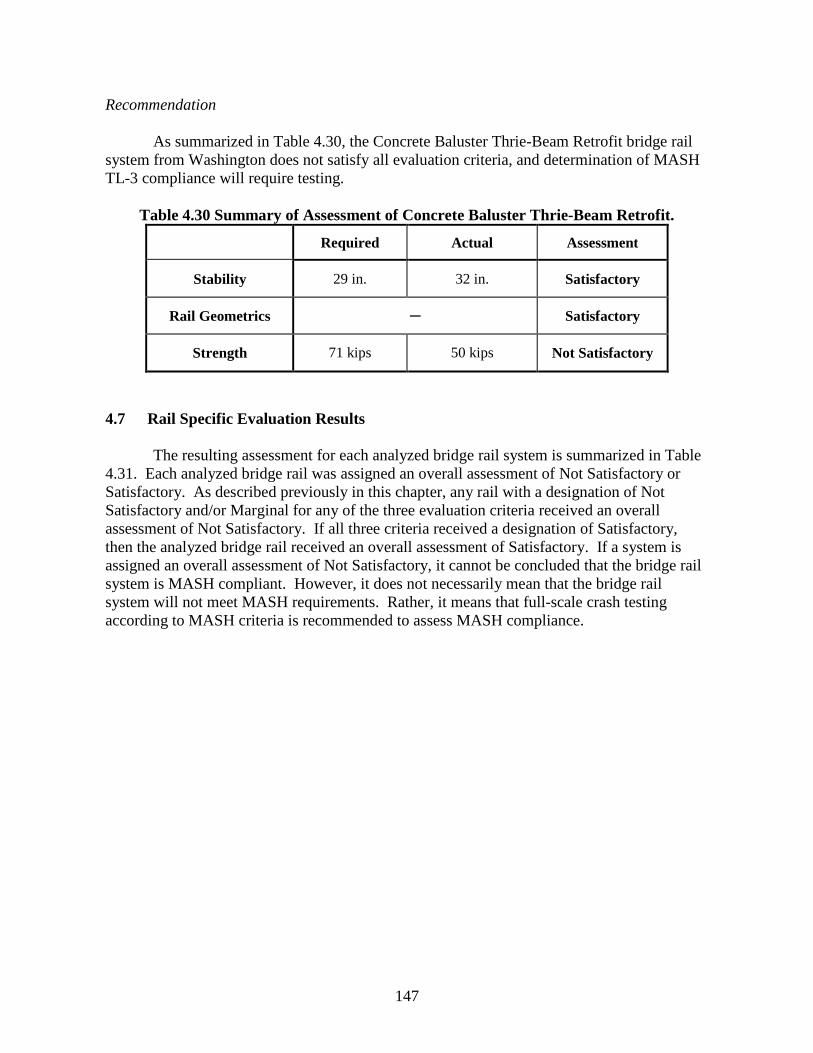
147
Recommendation As summarized in Table 4.30, the Concrete Baluster Thrie-Beam Retrofit bridge rail system from Washington does not satisfy all evaluation criteria, and determination of MASH TL-3 compliance will require testing.
Table 4.30 Summary of Assessment of Concrete Baluster Thrie-Beam Retrofit.
Required Actual Assessment
Stability 29 in. 32 in. Satisfactory
Rail Geometrics ─ Satisfactory
Strength 71 kips 50 kips Not Satisfactory
4.7 Rail Specific Evaluation Results The resulting assessment for each analyzed bridge rail system is summarized in Table 4.31. Each analyzed bridge rail was assigned an overall assessment of Not Satisfactory or Satisfactory. As described previously in this chapter, any rail with a designation of Not Satisfactory and/or Marginal for any of the three evaluation criteria received an overall assessment of Not Satisfactory. If all three criteria received a designation of Satisfactory, then the analyzed bridge rail received an overall assessment of Satisfactory. If a system is assigned an overall assessment of Not Satisfactory, it cannot be concluded that the bridge rail system is MASH compliant. However, it does not necessarily mean that the bridge rail system will not meet MASH requirements. Rather, it means that full-scale crash testing according to MASH criteria is recommended to assess MASH compliance.

148
Table 4.31 Rail Specific Evaluation Results. NCHRP Report
350 Test Level
Category Sub-Category System Name
Evaluated MASH
Test Level Stability Geometrics Strength Overall
Assessment
TL-4 Concrete-Only F-Shape
32" F-Shape (WV, PA, VA, LA, OR, MA, ME, FL, WS, TX)
TL-4 NS - - NS
TL-3 S S S S
42" F-Shape ( ME, FL, WS) TL-4 S S S S
TL-4 Concrete-Only Single Slope
42" Single Slope (WV, PA, VA,LA, OK,MD,MA)
TL-4 S S S S
36" Single Slope (TX,TN) TL-4 S S S S
TL-4 Combined (Traffic)
Curb, 2 Metal
Members
Alaska Multi-State Bridge Rail -32.5" (Alaska)
TL-4 NS - - NS
TL-3 S S S S
Two Tube Railing 36d (Wyoming)
TL-4 NS - - NS
TL-3 S M S NS

149
NCHRP Report
350 Test Level
Category Sub-Category System Name
Evaluated MASH
Test Level Stability Geometrics Strength Overall
Assessment
TL-4 Combination Traf/Ped
Traf /Ped, W/ Sidewalk
T4 Steel Bridge Rail (New Hampshire)
TL-4 S M NS NS
S-352series, Bridge Railing, Galvanized Steel Tubing /Concrete Combination (Vermont)
TL-4 S S S S
TL-5 Concrete-Only F-Shape
42" F-Shape (WV, PA, VA, OK, MD, MA)
TL-5 S S S S
45" F-Shape (IN) TL-5 S S S S
TL-4 Concrete-Only Post&Beam
Kansas Corral 32 inches without curb (Virginia)
TL-4 S M NS NS
Open concrete rail, 2’10” height (Nebraska)
TL-4 NS - - NS
TL-3 S M S NS
TL-4 Combination Traf/Ped
Traf /Ped, W/out
Sidewalk
S3-TL4 (Massachusetts) TL-4 S M S NS
4-Bar steel traffic/Bicycle railing (on curb)(Maine)
TL-4 S M S NS

150
NCHRP Report
350 Test Level
Category Sub-Category System Name
Evaluated MASH
Test Level Stability Geometrics Strength Overall
Assessment
TL-3 Combination Traf/Ped
Traf /Ped, W/out
Sidewalk
George Washington Memorial Parkway (Federal Lands)
TL-3 S M S NS
C221 (Texas) TL-3 S M S NS
TL-3 Combined (Traffic)
Curb, 2 Metal
Members
WY Two Tube (TL-3) SBB36c (Wyoming)
TL-3 S NS S NS
TL-4 Metal-Only Side-Mounted
Side Mounted Metal Bridge Railing (New Mexico)
TL-4 NS - - NS
TL-3 S M S NS
TL-4 Metal-Only Deck-Mounted
Type A42 Metal Bridge Railing (New Mexico)
TL-4 S S S S
TL-4 Combined (Traffic)
Parapet, 2 Metal
Members
Bridge railing, Aesthetic Parapet Tube (B-25-J) (Michigan)
TL-4 S S S S
TL-3 Combination Traf /Ped
Traf /Ped, W/ Sidewalk
Concrete Parapet with Structural Tubing STD-11-1 (Tennessee)
TL-3 S S S S

151
NCHRP Report
350 Test Level
Category Sub-Category System Name
Evaluated MASH
Test Level Stability Geometrics Strength Overall
Assessment
TL-4 Retrofit Retrofit
Concrete Baluster Thrie Beam Retrofit (Washington)
TL-4 S S NS NS

152
During the categorization, prioritization, and selection of bridge rails for analysis, it was noted that some DOTs used an identical or very similar bridge rail to the one selected for analysis. As a result, if the analyzed rail was considered MASH compliant, the similar or less critical systems can also be considered satisfactory. For example, the S-352 Series Bridge Railing submitted by Vermont DOT was prioritized in Chapter 2 and selected for analysis. The performed analysis concluded this system meets MASH criteria. As a result of the bridge rail categorization, it was found that there were several systems that had similar or less critical characteristics compared to the S-352 Series Bridge Rail. One of these systems is the BR-2-15 Bridge Railing submitted by Ohio DOT. As seen in Figure 4.52, the two systems are very similar and the only difference to note is that the tube located at 31 inches above grade is a HSS 4-inch x 3-inch x ¼ inch instead of a HSS 2 inch x 2 inch x 1/8 inch. The larger HSS tube can be considered less critical because it will provide more strength to the overall system and will provide less snagging potential for the vehicle.
(a) S-352 Series Bridge Rail

153
(b) BR-2-15 Bridge Rail
Figure 4.52 Comparison of S-352 Series and BR-2-15 Bridge Rails. This comparative analysis methodology was applied to all the analyzed bridge rails to determine those that were similar or less critical. Table 4.32 presents a list of all the submitted bridge rails that are considered similar or less critical than the ones that were analyzed and found to be MASH compliant. These similar or less critical bridge rail systems can be considered satisfactory according to MASH criteria and will not require further testing or evaluation.

154
Table 4.32 List of Similar or Less Critical Rails.
System Name MASH
Equivalency Assessment
Similar or Less Critical Rails
Alaska Multi-State Bridge Rail -32.5" (AK) Satisfactory TL-3
Alaska Multi State Bridge Rail (ND) Two-Tube Bridge Rail (Federal Lands)
2-Tube Curb Mount Rail (OR) PA Type 10M Bridge Barrier (PA)
Type 10M (CO)
S-352series, Bridge Railing, Galvanized Steel Tubing /Concrete Combination (VT) Satisfactory TL-4
PS-1 (IN) Bridge Railing, Aesthetic Parapet Tube (MI)
Bridge Sidewalk Railing with Concrete Barrier (OH)
Side Mounted Metal Bridge Railing (NM) Satisfactory TL-3 TST-1-99 Twin Steel Tube Bridge Railing (OH)
Type SM (IL) BR 226 (OR)
Type A42 Metal Bridge Railing (NM) Satisfactory TL-4 N/A Bridge railing, Aesthetic Parapet Tube (B-25-J)
(MI) Satisfactory TL-4 S-352 Galvanized Steel Tubing Concrete Combination Rail (VT)
Concrete Parapet with Structural Tubing STD-11-1 (TN) Satisfactory TL-3 C402 (TX)
42'' F-Shape (WV) Satisfactory TL-5 42'' F-Shape (PA, VA, OK, MD, MA) 45'' F-Shape (IN) Satisfactory TL-5 N/A
32'' F-Shape (WV) Satisfactory TL-3 32'' F-Shape (PA, VA, LA, OR, MA, ME, FL, WS, TX) 42'' F-Shape (ME) Satisfactory TL-4 42'' F-Shape (FL, WS)
42'' Single Slope (WV) Satisfactory TL-4 42'' Single Slope (PA, VA, LA, OK, MD, MA) 36'' Single Slope (TX) Satisfactory TL-4 36'' Single Slope (TN)

155
5 MASH IMPLEMENTATION COORDINATION EFFORTS Researchers coordinated with other research and testing agencies to share information regarding MASH implementation efforts and avoid duplication of work. TTI researchers communicated with research facilities, pooled fund programs, testing laboratories and user agencies to collect and share information regarding ongoing or planned MASH implementation efforts. TTI researchers are leading a MASH Implementation Coordination project through the Roadside Safety Pooled Fund. This project has the objective to coordinate MASH implementation testing activities at a national level. Collected data has been incorporated into a database that is available on the Roadside Safety Pooled Fund site under the MASH implementation page (https://www.roadsidepooledfund.org/mash-implementation/search/). The database contains information on MASH tested bridge rail systems as well as other categories of roadside safety hardware. The database is updated regularly to reflect input collected from State DOTs, FHWA, testing laboratories, and manufacturers. To date, the MASH database hosts a total of 33 entries under the “Bridge Rail” category. Table 5.1 summarizes the 33 bridge rails listed in the MASH database. Eight of these 33 entries are related to bridge rail systems which have FHWA eligibility letters. Three of the systems failed MASH evaluation criteria. Additional information collected through this project includes MASH implementation needs and testing plans. Table 5.2 presents information regarding bridge rail tests planned by various DOTs as known at the writing of this report.

156
Table 5.1 Bridge Rail Systems Listed on MASH Database.
Title Picture Description Proprietary/
Non-Proprietary
FHWA Eligibility
Letter
Caltrans Type 732SW Bridge Rail
Type 732SW bridge rail is a vertical, reinforced
concrete wall on a sidewalk with a
pedestrian steel tubular handrail or chain link fence on top (TL-2)
Non-Proprietary B259
MGS Bridge Rail
31-inch Midwest Guardrail System
(MGS) Bridge Rail
Non-Proprietary B228
West Virginia Timber Curb-Type
Bridge Barrier
TL-1 timber bridge railing for transverse, nail-laminated, timber
decks.
Non-Proprietary B198
Lake Pontchartrain Causeway Rail
(39″ tall)
Rockingham Precast T-LOC barrier Proprietary
Lake Pontchartrain Causeway Rail
(46″ tall)
46″ system comprised of 25″ concrete wall, posts and two steel
railings standing 9″ and 21″ above the wall respectively, atop a
10″curb
Proprietary

157
Table 5.1 Bridge Rail Systems Listed on MASH Database (Continued).
Title Picture Description Proprietary/
Non-Proprietary
FHWA Eligibility
Letter
Conti Half Shape Concrete Bridge Rail
Half-shape NJ pre-cast steel reinforced concrete barrier
Proprietary B226
TBTA Bridge Rail
Quadruple rail steel bridge rail 3 ft-6 inches in height, mounted on posts attached either to
a 49 ft-6inch bridge span (posts 3-9), or to a concrete foundation up to the bridge span and
beyond the bridge span.
Non-Proprietary B274
Side-Mounted Weak Post Guardrail
Attached to Culvert
Designed as treatment to continue W-beam guardrail across large
box culverts, compatible with the
MGS with or without blockouts such that an
approach transition would not be required
between the two barriers.
Non-Proprietary B264
32″ New Jersey Safety Shape Barrier (TL-3) (pickup truck
test)
32-in New Jersey shape bridge rail Non-Proprietary
32″ New Jersey Safety Shape Barrier
(TL-3) (passenger car test)
32-in New Jersey shape permanent rail Non-Proprietary

158
Table 5.1 Bridge Rail Systems Listed on MASH Database (Continued).
Title Picture Description Proprietary/
Non-Proprietary
FHWA Eligibility
Letter
Caltrans Side Bridge Rail ST-70
76 ft. test section of the bridge rail with 8 posts Non-proprietary
TxDOT Type T221
TxDOT concrete parapet (32” tall)
Non-Proprietary
TxDOT Type T80SS
Conc Single Slp Hvy Truck Traff Rail (42″
tall)
Non-Proprietary
TxDOT Type C223
T223 w/Steel Pipe Rail
(42″ tall)
Non-Proprietary
TxDOT Type C221
TxDOT T221 with steel
pipe rail (42″ tall)
Non-Proprietary

159
Table 5.1 Bridge Rail Systems Listed on MASH Database (Continued).
Title Picture Description Proprietary/
Non-Proprietary
FHWA Eligibility
Letter
TxDOT Type T1F Bridge Rail
TxDOT rail – steel posts w/ aluminum tube and opt drains (33″ tall)
Non-Proprietary
TxDOT Type T631
TxDOT rail with steel
posts and W-beam (TL-3) (31″ tall)
Non-Proprietary
TxDOT T223 (32″ tall)
TxDOT concrete beam and post w/ 6″ openings
(32″ tall)
Non-Proprietary
TxDOT Type T631LS
TxDOT rail with steel
posts and W-beam (TL-2) (31″ tall)
Non-Proprietary
TxDOT Type C2P (Picket Rail) (42″)
TxDOT steel rail with picket panels and opt
drains (42″ tall). – Standards currently
being developed (Taller version than T1P rail).
Non-Proprietary

160
Table 5.1 Bridge Rail Systems Listed on MASH Database (Continued).
Title Picture Description Proprietary/
Non-Proprietary
FHWA Eligibility
Letter
TxDOT Type T131RC
TxDOT retrofit guide for curbed structures
Non-Proprietary
TxDOT Type T222
Precast concrete barrier with smooth vertical
face and rail height of 32-3/4-in. Rail
anchored to 6-in thick reinforced concrete
cantilever deck.
Non-Proprietary
TxDOT Type T224 (42″ tall)
TxDOT concrete beam and post w/ 10′
openings (42″ tall) Non-Proprietary
TxDOT Type T221P
Precast T221 Rail (32.75″ tall) Non-Proprietary
Top-Mounted Weak-Post Guardrail
Attached to Culvert Non-Proprietary B262

161
Table 5.1 Bridge Rail Systems Listed on MASH Database (Continued).
Title Picture Description Proprietary/
Non-Proprietary
FHWA Eligibility
Letter
TxDOT Type T1P (Picket Rail)
TxDOT steel rail with picket panels and opt
drains (36’’ tall) Non-Proprietary
TxDOT Type SSTR on Pan-Formed Deck
36″ tall SSTR bridge rail on pan-formed
bridge deck Non-Proprietary
TxDOT Type SSTR
TxDOT concrete single slope traffic rail (36″
tall) Non-Proprietary
Manitoba Constrained-Width
Tall Wall Bridge Rail
49¼-inch high single-slope (9-degree) bridge
rail Non-Proprietary B-268
Caltrans Single Slope Type 60
Median Barrier (9.1 Degree Slope)
150-foot test section of Type 60 median barrier (9.1 degree slope angle)
Non-Proprietary

162
Table 5.1 Bridge Rail Systems Listed on MASH Database (Continued).
Title Picture Description Proprietary/
Non-Proprietary
FHWA Eligibility
Letter
New Jersey Safety Shape Barrier (TL-
4)
Failed TL-4 32-in New Jersey shape bridge rail. Non-Proprietary
32’’ New Jersey Safety Shape Barrier
(TL-4)
Failed 32-in New Jersey shape permanent rail for
TL-4 applications. Non-Proprietary
ST-10 Bridge Rail
Failed ST-10 Bridge Rail on a 30’’ x 20’’
trench footing foundation with a 6 inch
curb and a 3:1 slope 36’’ behind the article.
Non-Proprietary

163
Table 5.2 Planned Bridge Rail Systems Tests
MASH Test Number System Test Level -10 -11 -12 -20 -21 -22 Sponsor
S3-TL4 Bridge Railing, Sidewalk Mounted TL-4 X X X MassDOT S3-TL4 Bridge railing, Curb Mounted TL-4 X X X MassDOT
Highway Guardrail to Bridge Rail Transition, sidewalk mounted TL-4 X X X MassDOT Highway Guardrail to Bridge Rail Transition, curb mounted TL-4 X X X MassDOT
Caltrans Type ST-75 TL-4 X X X Caltrans Caltrans Concrete Barrier Type 85 TL-4 X X X Caltrans
36" Vertical Parapet TL-4 X TXDOT Texas T402/C402 TL-4 X X X TXDOT
Texas C402 Bridge Rail TXDOT Texas C412 Bridge Rail TL-5 X TXDOT Texas C411 Bridge Rail TL-2 X X TXDOT Texas T1W Bridge Rail TL-3 X X TXDOT Texas C1W Bridge Rail TL-4 X TXDOT Texas C66 Bridge Rail TL-4 X TXDOT
Restrained Single Slope Median Barrier on Bridge Deck TL-4 X TXDOT Thrie Beam Bridge Rail Retrofit TL-4 X X X LADOT Steel Rail Bridge Rail Retrofit TL-3 X X LADOT
Redesign of Alaska Multi-State (2-Tube) Bridge Rail TL-4 X X X State of Alaska
Thrie Beam Transition to Alaska Multi-State (2-Tube) Bridge Rail TL-4 X X X State of Alaska
W-beam Transition to Alaska Multi-State Bridge Rail TL-3 X X State of Alaska
Combination Traf/Ped/Bic Rail with 36” Single Slope Barrier TL-4 X FDOT 31” Combination Concrete and Tubular Steel Rail TL-3 X X CoDOT


165
6 ELIGIBILITY LETTERS Chapter 4 analyses identified bridge rails considered to have justification for MASH eligibility without retesting. Eligibility request forms were developed for review and consideration by user agencies. The eligibility request forms for each bridge rail system considered MASH compliant are included in Appendix D of this report. It should be noted that FHWA recently released an open letter dated May 26, 2017 (FHWA Letter) regarding the FHWA eligibility letter review process. FHWA has used this letter to inform interested parties of important changes to the Federal-aid eligibility process for roadside safety hardware systems. A copy of the letter is included as Appendix C to this report. This letter notifies that FHWA is implementing immediate process changes on how requests for Federal-aid eligibility letters for roadside safety hardware systems are accepted. Below are some extracts from the FHWA Open Letter.
1. “Moving forward, in order for manufacturers and States to qualify for a FHWA Federal-aid eligibility letter, all roadside hardware devices must complete the full suite of recommended tests as described in AASHTO MASH.” (…) “Manufacturers and States that received an eligibility letter under AASHTO’s MASH standards and did not run the full suite of tests will be required to run the remaining tests in order to retain the Federal-aid eligibility letter.”
2. FHWA will no longer provide Federal-aid eligibility letters for modifications made to an AASHTO MASH-crash tested device.
FHWA will no longer accept and review any eligibility requests based solely or in part on engineering analysis. Thus, the eligibility requests developed under this project will not be considered by FHWA. However, the eligibility justification can still be reviewed and considered by individual State DOTs. The FHWA Office of Safety website (revised 4/8/16) states the following:
The following Frequently Asked Questions were developed to help clarify the roles of the Division and Headquarters Offices in determining whether hardware is eligible for reimbursement under the Federal-Aid Highway Program as discussed in the FHWA Federal-Aid Reimbursement Eligibility Process for Safety Hardware Devices dated November 12, 2015. Q1: Does all roadside safety hardware need a FHWA Eligibility Letter in order to be eligible for reimbursement on projects on the NHS? A1. No. Eligibility Letters are provided as a service to the States and are not a requirement for roadside safety hardware to be eligible for reimbursement.

166
Q2: If a State does not request an FHWA Eligibility Letter for a safety hardware device, what documentation can a Division Office rely on that the device is eligible for Federal-aid reimbursement? A2: When approving the State's standard plans or qualified products lists (QPLs), the Division Office may rely on a certification from the State DOT indicating that the hardware satisfies MASH or NCHRP 350 criteria. The State DOT should keep on file documentation supporting this certification.

167
7 SUMMARY AND CONCLUSIONS 7.1 Overview
MASH incorporated significant changes and additions to the procedures for the safety performance of roadside safety hardware, including new design vehicles that better reflect the changing character of vehicles using the highway network. These changes place a greater safety demand on roadside safety hardware.
When the second edition of MASH published in 2016, a MASH implementation
agreement was jointly adopted by AASHTO and the Federal Highway Administration (FHWA). The implementation agreement establishes dates for implementing MASH compliant safety hardware for new installations and full replacements on the National Highway System (NHS). The implementation date for bridge rails is December 31, 2019.
Under this project, research was performed to determine which bridge rails need to be retested to MASH criteria and which, if any, could be "grandfathered" based on equivalency between MASH and NCHRP Report 350 test levels. The research approach included identifying, categorizing, and prioritizing bridge rail systems, determining MASH equivalent test levels for different categories of bridge rails tested under previous criteria, performing detailed analysis of selected bridge rail systems, and developing justification for systems considered to be MASH compliant without further testing.
7.2 Identification and Prioritization of Bridge Rail Systems
An electronic, web-based survey was used to obtain input from State Departments of Transportation (DOTs). The survey requested information regarding the type and frequency of use of non-proprietary domestic bridge rails in each state. A total of 34 survey responses were collected, including 33 DOT Agencies and FHWA Federal Lands. The submitted bridge rail systems were categorized and prioritized based on weighted frequency of use.
7.3 MASH Test Level Equivalency
As part of the effort to evaluate equivalency between NCHRP Report 350 and MASH test levels, three key criteria were considered: stability, strength, and geometrics. Available data from full-scale crash tests and finite element simulations were used in the analysis effort. This included establishing minimum rail heights and lateral impact loads for different test levels, and examining the relevance of existing geometric relationships that relate to vehicle snag potential. The minimum rail heights were found to be 29, 36, and 42 inches for MASH TL-3, TL-4, and TL-5, respectively. Design impact loads used in the analyses are presented in Table 4.2.
The resulting test level equivalencies are presented in Table 7.1. NCHRP Report 350
TL-5 is considered equivalent to MASH TL-5. NCHRP Report 350 TL-3 and TL-4 are not globally equivalent but are dependent upon the bridge rail category. NCHRP Report 350 TL-3 and TL-4 solid concrete parapets and metal rails on concrete parapets with a parapet height greater than 24 inches are considered acceptable under MASH TL-3. NCHRP Report 350

168
TL-3 and TL-4 concrete post and beam, metal rail deck, or curb mounted systems can be found acceptable under MASH TL-2.
Table 7.1 Summary of Global Test Equivalency for NCHRP Report 350 Bridge Rail
Systems. NCHRP Report 350 Rail System
Type
MASH Test Level
TL-2 TL-3 TL-4 TL-5
Solid Concrete Parapet TL-2 TL-3
TL-4 TL-5
Concrete Beam-and-Post
TL-2 TL-3 TL-4
TL-5
Metal Beam-and-Post Deck Mounted
TL-2 TL-3 TL-4
TL-5
Metal Beam-and-Post on Curb
TL-2 TL-3 TL-4
TL-5
Metal Beam-and-Post on Concrete
Parapet* TL-2 TL-3
TL-4 TL-5
* Concrete parapet height greater than or equal to 24 inches
7.4 Rail Specific Analyses
The prioritized bridge rail systems were analyzed using the analysis methodology outlined in Chapter 4. Out of the 22 bridge rail systems analyzed, 12 were given a Satisfactory overall assessment. To receive an overall assessment of Satisfactory, a bridge rail system must receive a Satisfactory designation for each of the three evaluation criteria: stability, rail geometrics, and strength. Other bridge rail systems that were similar or less critical than the 12 systems with a Satisfactory overall assessment are also considered Satisfactory. This resulted in a total of 48 bridge rail systems found to be MASH compliant.
The bridge rail systems that were given a Not Satisfactory overall assessment had a
Marginal or Not Satisfactory designation for at least one of the three criteria. Note that a Not Satisfactory overall assessment does not mean that the investigated bridge rail system will not meet MASH criteria. Rather, it means that a determination regarding MASH compliance cannot be confidently made and further testing in accordance with MASH criteria is recommended. 7.5 MASH Implementation Coordination Effort
Researchers coordinated with research facilities, pooled fund programs, testing laboratories and user agencies to collect and share information regarding completed or planned MASH bridge rail crash tests. Additionally, TTI researchers are leading a MASH

169
Implementation Coordination project through the Roadside Safety Pooled Fund. This project has the objective to coordinate MASH implementation testing activities at a national level.
Collected data has been incorporated into a database that is available on the Roadside
Safety Pooled Fund site under the MASH implementation page (https://www.roadsidepooledfund.org/mash-implementation/search/). The database contains information on MASH tested bridge rail systems as well as other categories of roadside safety hardware. To date, the MASH database hosts a total of 33 entries under the “Bridge Rail” category. These systems are summarized in Chapter 5. MASH implementation testing plans were also collected. Twenty-two bridge rail systems ranging from TL-2 to TL-5 are currently programmed for full-scale crash testing by various state DOTs at the writing of this report. These systems are summarized in Chapter 6. 7.6 Eligibility Letters
Eligibility request forms were developed for each of the analyzed bridge rail systems that received a Satisfactory overall designation. An open letter dated May 26, 2017 states that FHWA will no longer accept and review any eligibility requests based solely or in part on engineering analysis. Thus, the eligibility requests developed under this project will not be considered by FHWA. However, the eligibility justification can still be reviewed and considered by individual State DOTs. These eligibility forms are presented in Appendix D.


171
REFERENCES 1. Ross, H.E., D.L. Sicking, R.A. Zimmer, and J.D. Michie. Recommended Procedures for
the Safety Performance Evaluation of Highway Features, National Cooperative Highway Research Program Report 350. Transportation Research Board, National Research Council, Washington, D.C., 1993.
2. American Association of State Highway and Transportation Officials. Manual for Assessing Safety Hardware. AASHTO Subcommittee on Bridges and Structures, Washington, D.C., 2009.
3. American Association of State Highway and Transportation Officials. Manual for Assessing Safety Hardware. AASHTO Subcommittee on Bridges and Structures, Washington, D.C., 2016.
4. Federal Highway Administrations. Bridge Railings. http://safety.fhwa.dot.gov/roadway_dept/policy_guide/road_hardware/barriers/bridgerailings/docs/appendixb5.pdf Last Retrieved April 1st 2016.
5. Wright, F. G. Bridge Analysis Memorandum. http://safety.fhwa.dot.gov/roadway_dept/policy_guide/road_hardware/barriers/bridgerailings/docs/bridgerail_analysis_may16.pdf, Last Retrieved April 1st 2016.
6. Sheikh, N.M., R.P. Bligh, and W.L. Menges. Determination of Minimum Height and Lateral Design Load for MASH Test Level 4 Bridge Rails. Report No. 9-1002-5. Texas A&M Transportation Institute, College Station, Texas, 2011.
7. Bligh, R.P., J.L. Briaud, A. Abu-Odeh, D.O. Saez B., L.S. Maddah, and K.M. Kim. Design Guidelines for Test Level 3 (TL-3) Through Test Level 5 (TL-5) Roadside Barrier Systems Placed on Mechanically Stabilized Earth (MSE) Retaining Wall. NCHRP Project No. 22-20(2). Texas A&M Transportation Institute, College Station, Texas, 2017.
8. Polivka, K.A., D.L. Sicking, B.W. Bielenberg, R.K. Faller, J.R. Rohde, and J.D. Reid. Performance Evaluation of the Permanent New Jersey Safety Shape Barrier – Update to NCHRP 350 Test No. 4-12 (2214NJ-2). Report No. TRP-03-178-06. Midwest Roadside Safety Facility, Lincoln, Nebraska, 2006.
9. Bullard, D.L., R.P. Bligh, and W.L. Menges. Appendix A: MASH-08 TL-4 Testing and Evaluation of the New Jersey Safety Shape Bridge Rail. NCHRP Project 22-14, College Station, Texas, 2008.

172
10. Williams, W.F., J. Ries, R.P. Bligh, and W. Odell. Design & Full Scale Testing of Aesthetic TxDOT Type T224 Bridge Rail for MASH TL-5 Applications. TRB Paper No. 17-06469. Transportation Research Board, Washington, DC, 2017.
11. Caldwell, C. Development of Aesthetic, Low-Maintenance Guardrail System Alternatives. FHWA Report No. FHWA/CA15-0918. California Department of Transportation, Sacramento, CA, 2015.
12. Bligh, R.P., J. Briaud, K. Kang-Mi, and A. Abu-Odeh. Design of Roadside Barrier Systems Placed on MSE Retaining Walls. NCHRP Project 22-20, College Station, Texas, 2008.
13. Williams, W.F., R.P. Bligh, and W.L. Menges. MASH Test 3-11 of the TxDOT T222 Bridge Rail. Report No. 9-1002-12-13. Texas A&M Transportation Institute, College Station, Texas, 2014.
14. Bligh, R.P. Roadside Crash Testing Program for Design Guidance and Standard Detail Development. Report No. 0-5210-9. Texas A&M Transportation Institute, College Station, Texas, 2010.
15. Buth, E.C., W.F. Williams, R.P. Bligh, W.L. Menges, and B.G. Butler. Tests 4, 5, & 6: NCHRP Report 350 Testing of the Texas Type 202 Bridge Rail. Report No. 1804-3. Texas A&M Transportation Institute, College Station, Texas, 1998.
16. Polivka, K.A., J.R. Rohde, D.L. Sicking, R.K. Faller, J.D. Reid, and J.C. Holloway. Safety Performance Evaluation of the Nebraska Open Bridge Rail on an Inverted Tee Bridge Deck. Report No. TRP-03-133-04. Midwest Roadside Safety Facility, Lincoln, Nebraska, 2004.
17. Bligh, R.P., and W.L. Menges. MASH Test 3-11 on the Texas T101 Bridge Rail. Report No. 9-1002-1. Texas A&M Transportation Institute, College Station, Texas, 2010.
18. Williams, W.F., R.P. Bligh, and W.L. Menges. TxDOT T131 Bridge Rail. Report No. TM-9-1002-1. Texas A&M Transportation Institute, College Station, Texas, 2011.
19. Caldwell, C. Development of Aesthetic, Low-Maintenance Guardrail System Alternatives. Report No. FHWA/CA15-0918. California Department of Transportation, Sacramento, California, 2015.

173


175
APPENDIX A: Survey

176

177

178

179
APPENDIX B: Rail Analysis Spreadsheets The spreadsheet templates that were developed for the different analyzed bridge rails are included in this Appendix. The spreadsheets were broken down into stability, geometric, and strength evaluation sections.

180
Appendix B.1: Aesthetic Parapet Tube B-25-J (Michigan) Details
Stability
Geometrics

181

182
Strength

183

184

185

186

187

188
Appendix B.2: Concrete Parapet with Structural Tubing (Tennessee) Details
Stability
Geometrics

189

190
Strength

191

192

193

194

195

196

197

198
Appendix B.3: S-352 Series Steel Tubing Concrete Combination (Vermont) Details
Stability
Geometrics

199

200
Strength

201

202

203

204

205

206

207

208

209
Appendix B.4: Kansas Corral 32in without curb (Virginia) Details
Stability
Geometrics

210

211

212
Strength

213

214

215
Appendix B.5: Open Concrete Rail (Nebraska) Details
Stability
Geometrics

216

217
Strength

218

219

220
Appendix B.6: 4-Bar Steel Traffic Bicycle Railing on Curb (Maine) Details
Stability

221
Geometrics

222

223
Strength

224

225

226

227
Appendix B.7: Alaska Multi-State Bridge Rail (Alaska) Details
Stability

228
Geometrics

229

230
Strength

231

232

233
Appendix B.8: George Washington Memorial Parkway (Federal Lands) Details
Stability

234
Geometrics

235
Strength

236

237

238

239
Appendix B.9: S3-TL4 (Massachusetts) Details
Stability
Geometrics

240

241
Strength

242

243

244

245
Appendix B.10: Side Mounted Metal Bridge Railing (New Mexico) Details
Stability

246
Geometrics

247
Strength

248

249

250

251
Appendix B.11: T4 Steel Bridge Rail (New Hampshire) Details
Stability

252
Geometrics
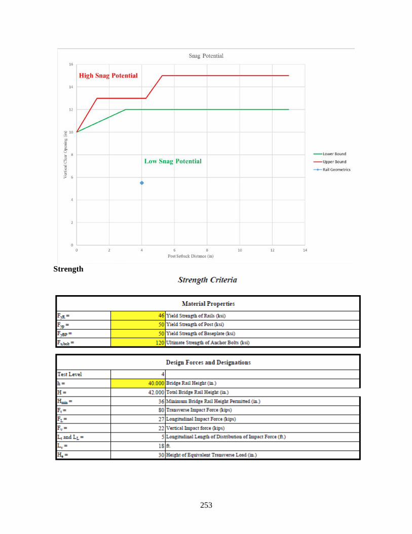
253
Strength

254

255

256

257
Appendix B.12: Two Tube 36c (Wyoming) Details
Stability
Geometrics

258

259
Strength

260

261

262
Appendix B.13: Two Tube Railing-36d (Wyoming) Details
Stability
Geometrics

263

264
Strength

265

266

267
Appendix B.14: Type A42 Metal Bridge Railing (New Mexico) Details
Stability
Geometrics

268

269
Strength

270

271

272

273
Appendix B.15: 32-inch F-Shape (West Virginia) Details
Stability

274
Strength

275

276

277
Appendix B.16: 36-inch Single Slope (Tennessee) Details
Stability

278
Strength

279

280

281

282
Appendix B.17: TL-4 42-inch F-Shape (Florida) Details
Stability

283
Strength

284

285

286

287
Appendix B.18: TL-5 42-inch F-Shape (Pennsylvania) Details
Stability

288
Strength

289

290

291
Appendix B.19: 42-inch Single Slope (New Mexico) Details
Stability

292
Strength

293

294

295

296
Appendix B.20: 45-inch F-Shape (Indiana) Details
Stability

297
Strength

298

299

300
Appendix B.21: C221 Bridge Rail (Texas) Details
Stability

301
Strength

302

303

304
Appendix B.22: Concrete Baluster Thrie-Beam Retrofit (Washington) Details
Stability

305
Strength
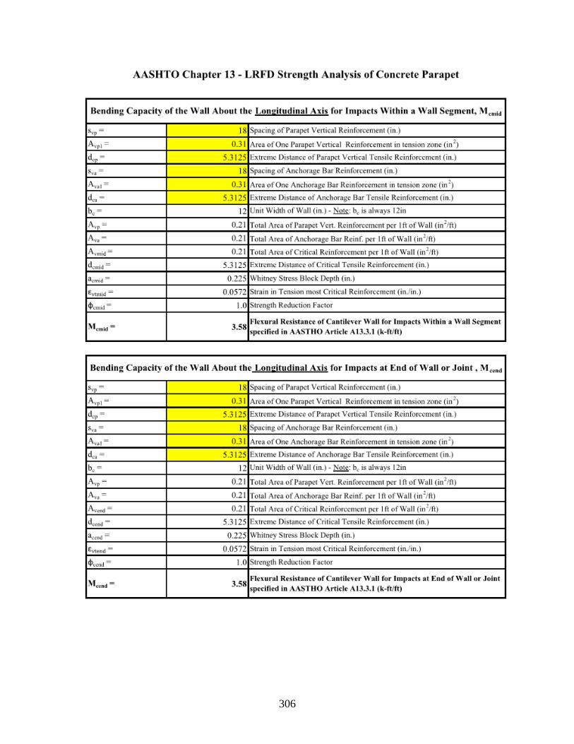
306

307

308

309
APPENDIX C: FHWA Open Letter

310

311
APPENDIX D: FHWA Eligibility Letter Requests FHWA eligibility letters were completed for the analyzed bridge rail systems that can be considered satisfactory according to MASH evaluation criteria. The eligibility letters are attached below for the different satisfactory bridge rail systems.

312
Appendix D.1: Aesthetic Parapet Tube B-25-J

313

314

315

316

317
Appendix D.2: Alaska Multi-State Bridge Rail (Alaska)

318

319

320

321
Appendix D.3: Concrete Parapet with Structural Tubing (Tennessee)

322

323

324

325
Appendix D.4: S-352 Series Steel Tubing Concrete Combination (Vermont)

326

327

328
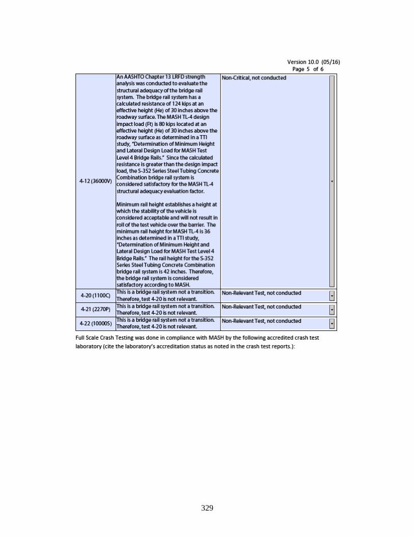
329

330

331
Appendix D.5: Side Mounted Metal Bridge Railing (New Mexico)

332
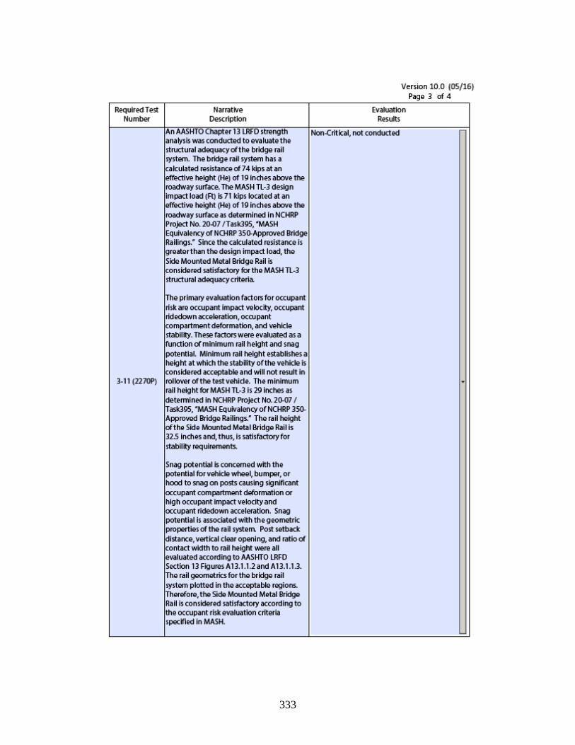
333

334

335
Appendix D.6: Type A42 Metal Bridge Railing (New Mexico)

336

337

338

339

340
Appendix D.7: 32-inch F-Shape (West Virginia)

341
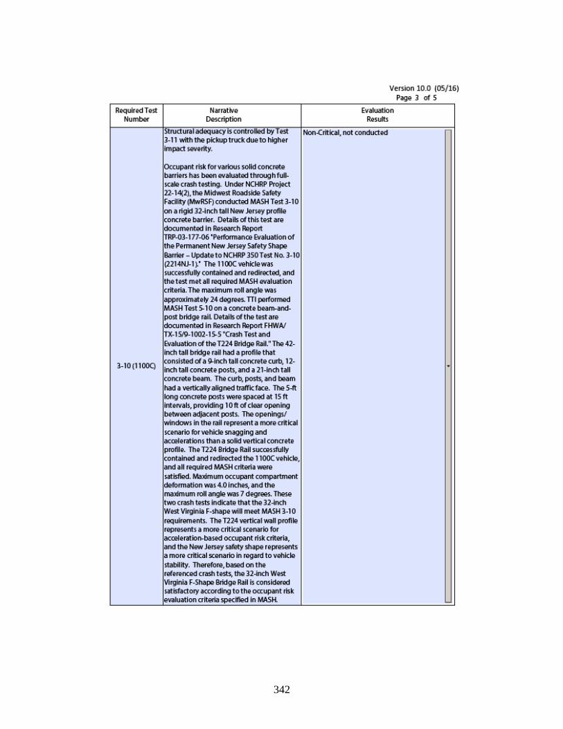
342

343

344

345
Appendix D.8: 36-inch Single Slope (Tennessee)

346

347

348

349

350

351
Appendix D.9: TL-4 42-inch F-Shape (Florida)

352

353

354

355

356

357
Appendix D.10: 42-inch Single Slope (New Mexico)

358

359

360

361

362

363
Appendix D.11: TL-5 42-inch F-Shape (Pennsylvania)

364

365

366

367

368

369
Appendix D.12: 45-inch F-Shape (Indiana)

370

371

372

373

374
Related Documents


![Midwest Roadside JEK/TJD Safety Facilitymwrsf.unl.edu/researchhub/files/Report324/AZ_roundPost_R7.pdf · BCT anchors are placed in 3' [914] holes, then backfilled and ... 12/23/2015](https://static.cupdf.com/doc/110x72/5a898cbe7f8b9a14748eb2f2/midwest-roadside-jektjd-safety-anchors-are-placed-in-3-914-holes-then-backfilled.jpg)
