DENISON HYDRAULICS Premier Series open loop pump controls series P080 service information Publ. S1-AM027 Internet: http://www.denisonhydraulics.com E-mail: denison@ denisonhydraulics.com www.comoso.com

Welcome message from author
This document is posted to help you gain knowledge. Please leave a comment to let me know what you think about it! Share it to your friends and learn new things together.
Transcript

DENISON HYDRAULICSPremier Series
open loop pump controlsseries P080
service information
Publ. S1-AM027
Internet: http://www.denisonhydraulics.com E-mail: denison@ denisonhydraulics.com
www.comoso.com

CONTENTS
2
typical characteristics-------------------------------------------------------------------------------fluid connections-------------------------------------------------------------------------------------introduction------------------------------------------------------------------------------------------
general---------------------------------------------------------------------------------------------description-----------------------------------------------------------------------------------------pressure compensator----------------------------------------------------------------------------remote compensator control---------------------------------------------------------------------load sensing control------------------------------------------------------------------------------torque limiter--------------------------------------------------------------------------------------rotary servo control-------------------------------------------------------------------------------hydraulic stroker----------------------------------------------------------------------------------electric stroker-------------------------------------------------------------------------------------pressure compensator override and torque limiter override--------------------------------
troubleshooting chart-------------------------------------------------------------------------------pressure compensator parts list-------------------------------------------------------------------
figure 1 & parts list, maximum volume stop--------------------------------------------------figure 2 & parts list, maximum volume handwheel-------------------------------------------
compensator disassembly, assembly, test------------------------------------------------------- figure 3 & parts list, compensator cap--------------------------------------------------------- buck-up cap disassembly, assembly------------------------------------------------------------ figure 4 & parts list,buck-up cap----------------------------------------------------------------
electric stroker parts list----------------------------------------------------------------------------electric stroker disassembly, assembly, test---------------------------------------------------figure 5, electric stroker-------------------------------------------------------------------------- figure 6, servo cap--------------------------------------------------------------------------------- parts lists for figure 5 and figure 6-------------------------------------------------------------control cap disassembly, assembly-------------------------------------------------------------figure 7 & parts list, control cap---------------------------------------------------------------- torque limiter override disassembly & assembly--------------------------------------------- figure 8 & parts list, torque limiter override-------------------------------------------------- figure 9 & parts list, torque limiter override cap--------------------------------------------- torque limiter override test and adjustment---------------------------------------------------compensator override disassembly, assembly, test-------------------------------------------figure 10 & parts list, compensator override--------------------------------------------------
hydraulic stroker parts list-------------------------------------------------------------------------hydraulic stroker disassembly, assembly, test-------------------------------------------------figure 11 & parts list, hydraulic stroker--------------------------------------------------------
torque limiter parts list-----------------------------------------------------------------------------torque limiter disassembly & assembly--------------------------------------------------------figure 12, torque limiter--------------------------------------------------------------------------figure 13, torque limiter cap--------------------------------------------------------------------- parts lists for figure 12 and figure 13----------------------------------------------------------torque limiter test and adjustment--------------------------------------------------------------
rotary servo parts list-------------------------------------------------------------------------------rotary servo disassembly, assembly, test-------------------------------------------------------figure 14 & parts list, rotary servo-------------------------------------------------------------
load sensing control parts list---------------------------------------------------------------------load sensing control disassembly, assembly, test---------------------------------------------figure 15 & parts list, load sensing control---------------------------------------------------
hydraulic circuits------------------------------------------------------------------------------------pressure compensator----------------------------------------------------------------------------pressure compensator with load sensing configuration--------------------------------------torque limiter--------------------------------------------------------------------------------------manual rotary servo------------------------------------------------------------------------------manual rotary servo with compensator override---------------------------------------------manual rotary servo with torque limiter override--------------------------------------------electric stroker-------------------------------------------------------------------------------------electric stroker with compensator override----------------------------------------------------electric stroker with torque limiter override---------------------------------------------------hydraulic stroker---------------------------------------------------------------------------------- hydraulic stroker with compensator override-------------------------------------------------hydraulic stroker with torque limiter override------------------------------------------------load sensing control------------------------------------------------------------------------------
stroker performance--------------------------------------------------------------------------------installation drawings--------------------------------------------------------------------------------controls key sheet------------------------------------------------------------------------------------technical data conversions-------------------------------------------------------------------------
Pump seal kit (includes all controls) S22-15647 See key sheet pg. 45 for information
PAGE3344444444455567789
101011121313141515161718192021222324252627272829303132333435363636363737373838383939394040414546
www.comoso.com

3
CHARACTERISTICS
Specification
• compensator response off-strokeon-stroke
(per SAE J745 Apr. 87 at 345 bar)• compensator adjustment
• minimum compensating pressure (comp, loadsensing, torque limiter)
• minimum servo pressure for 500 bar systempressure• minimum compensator override pressure at 48,3bar servo pr. (servo, elec. & hyd. str. )
• torque limiter adjustment range code Jcode K
• typ. servo & stroker response @ 83 bar servopressure, zero to full stroke and vice versa
• servo flow required for this response (E, H, R10controls)• servo flow required for this response (-1J, -1K,*1P controls)
• maximum servo pressure
• servo shaft rotation, 0 to full volume
• displacement/rev./degree servo shaft rotation
• torque to turn rotary servo shaft
• hydraulic stroker control pressure 0 disp.full disp.
• electric stroker control amps (24V) 0 disp.full disp.
• electric stroker control amps (12V) 0 disp.full disp.
pulse width modulation frequency:Denison Hydraulics electric stroker accessories
mating connector: Din 43650 type AF part no.167-10008-8 (provided)
Jupiter driver S20-14078Jupiter power supply S20-11715Options card S20-ll716Venus controller 020-14103
• electric stroker nominal coil resistance (24v. coil)• electric stroker nominal coil resistance (12v. coil)
• handwheel turns, full to zero stroke
• torque to turn handwheel @ 70 bar• torque to turn handwheel @ 500 bar
• port C1, C2 (cylinder gage ports)• port E (electric stroker control pressure inlet)• port H (hydraulic stroker control pressure inlet) • port LS (load sensing port) • port V (compensator vent) • port X (rotary servo, electric & hydraulic strokerservo inlet)
NOTES*on-stroke response for compensator override isdetermined by servo/stroker response.**add case pressure
Term
sec.sec.
bar/turn
bar
bar
bar
NmNm
sec.
l/min.
l/min
bar
degrees
cc/rev/deg.
Nm
barbar
mAmAmAmAHz
ohmsohms
turns
NmNm
BSPPBSPPBSPPBSPPBSPPBSPP
P080
0,0600,110*
138
13,8**
48,3**
84,5**
90 - 170over 170
<0,35
11,4
15,2
103
56
1,43
2,3
3,4514,5
125290250580
100-150
4110
9
920
1/41/41/41/43/83/8
TYPICAL CHARACTERISTICS
FLUID CONNECTIONS
www.comoso.com

The instructions contained in this manual cover complete disassembly and reassembly of the con-trols. Before proceeding with the disassembly or reassembly of any unit, this manual should bestudied in order to become familiar with proper order and parts nomenclature.
A piloted three-way valve spool and sleeve combination is the nucleus of the control function. Forthe compensator, torque limiter and load sensing controls, system pressure is applied to the inputport of the valve, and to one end of the spool. A small orifice feeds this pressure to the other end ofthe spool,. A spring on this end biases the spool to normally port the control piston to pump case .This control piston links to the pump cam. On the opposite side of the control piston, a spring anda piston connected to system pressure along with pump timing forces, combine to put the pumpon stroke.
A spring-loaded cone and seat connected to the spring end of the three-way spool establishes anadjustable pressure limit on this end of the spool. When system pressure reaches this value, flowthrough the spool creates a pressure difference across the spool. At approximately 13,8 bar differ-ence, the spool shifts toward the spring, re-directing the control cylinder port to pressure. This pres-sure applied to the control piston overcomes the forces putting the pump on stroke, causing thepump to reduce displacement. When the pump pressure drops, the spool shifts the other way tomaintain the pump pressure at approximately 13,8 bar above the controlled pressure on the springside. The spring end of this three-way spool may also be connected to a remote pressure control,through the vent port, V. Flow through this port, when controlling, is approximately 1,9 l/m.
For load sensing, this “V” port is connected to the load. The valve between the pump and the loadmeters the flow. The pump provides the flow to develop 13,8 bar drop across the valve indepen-dent of the load pressure and thus establishes a constant flow independent of operating pressure.Adjustment of spring load on the three-way spool allows precise control of the differential pressure.
Where the approximately 1,9 l/m vent flow is unacceptable, and where multiple loads are to becontrolled, a load sensing control is available. In the load sensing control, the vent flow is modulat-ed by a valve which senses load pressure and establishes the pump compensator pressure at 21bar above load pressure. There is essentially no flow in the sensing line.
For constant torque, system pressure and pump displacement are interrelated by the formulaP•V=C. As pressure increases, displacement must reduce, and vice versa.
A linkage to the pump control piston slides a spool over a pin.. The pin contains a cross drilledhole, and a connecting drilling to one end. This pin passes through a bore in the torque limiterhousing connecting to the vent port of the compensator. The pressure in the vent port applies aforce on the pin, which is resisted on the other end by a two spring combination.
The pin positions itself to where the vent pressure force on the one end is balanced by the springforce on the other end. When the cross drilled hole opens, it causes the three-way spool to shift todirect system pressure into the control piston, reducing stroke. The linkage to the control pistoncauses the spool to move in the direction to close the cross-drilled hole. Thus, for every position ofthe pin, there is a corresponding position for the control piston. The position of the pin is deter-mined by the pressure, the spring rate, and the initial adjustment on the springs. As pressureincreases, pump stroke must reduce.
At low pressure, only the outer spring contacts the spool. As pressure increases, the second springalso makes contact. Thus the rate of change of pressure starts at a low initial rate when the pumpis at full stroke and changes to a high rate at reduced stroke, to approximate the P•V=C relation-ship. The normal compensator function is retained to provide a maximum pressure limit.
The rotary servo control is mounted on the off-stroke side of the control piston. The control pistonhas a large diameter on this side, and a smaller diameter on the opposite side. Servo pressure isconnected to the input port on the three-way valve, and also to the smaller diameter side of thecontrol piston.
When the three-way spool is at rest, this end of the control piston is ported to tank, and servo pres-sure applied to the opposite, smaller diameter piston causes the rocker cam to stroke to minimum.When the three-way spool shifts, pressure is directed into the larger diameter of the control pistoncausing the cam to shift towards full stroke.
The pin as described for the torque limiter, is spring loaded against a mechanism which convertsrotary motion of the input shaft to linear motion of the pin, thus positioning pump stroke proportion-ately to input shaft rotation.
In the hydraulic stroker, a spring loaded piston is attached to this pin. A control pressure of 3,45 barcauses the piston to commence to move against the spring, to position the pin in proportion to thecontrol pressure, and thus cause the pump to stroke in proportion to control pressure. Full stroke isachieved at 14,5 bar control pressure.
INTRODUCTION
GENERAL
DESCRIPTION OF OPERATION
PRESSURE COMPENSATOR
PRESSURE COMPENSATORLOAD SENSING CONFIGURA -TION
LOAD SENSING CONTROL
TORQUE LIMITER
ROTARY SERVO CONTROL
HYDRAULIC STROKER
4 www.comoso.com

By mounting an electrically modulated pressure control valve on the hydraulic stroker to establishthe control pressure, pump stroke is controlled by an electrical signal. At approximately 125 mAelectrical signal, the pump commences to stroke, and at approximately 290 mA, the pump will beat full stroke. The Denison Hydraullics Venus controller 020-14103, Jupiter S20-14078, or JupiterS20-14087 may be used to drive the electric stroker.
An override pressure compensator or torque limiter control is mounted on the on-stroke side of thecontrol piston opposite the servo, hydraulic or electric stroker. The port on the override controlwhich normally connects to cylinder in the at-rest position is connected to servo, allowing normalstroker control. When system pressure or torque exceed the override setting, system pressure issupplied to the smaller diameter control piston to override the command and reduce stroke to thecompensator or torque limiter setting.
INTRODUCTION
ELECTRIC STROKER
PRESSURE COMPENSATORAND TORQUE LIMITER OVER-RIDE
5
TROUBLESHOOTING CHARTEffect of T rouble Possible Cause Fault Which Needs RemedyCompensator , Compensator OverrideLow system pressure Compensator malfunction Dirt in spool orifice
Damaged cone or seatBroken differential spring Improperly adjusted differential spring
Failure to compensate Differential adjustment Differential set too highSluggish response Differential adjustment Differential set too lowWide pressure fluctuations (hunting) Excessive line capacitance Install check valve near pump outletLoad Sensing ControlLow system pressure See aboveFailure to compensate See aboveSluggish response Differential adjustment Differential set too high
Modulating valve Air in load sensing lineWide pressure fluctuations (hunting) Excessive line capacitance Install check valve near pump outlet
Modulating valve Air in load sensing lineExcessive pressure drop across Differential adjustment Differential set too highcontrol valvePoor control of flow Differential adjustment Differential set too lowTorque Limiter , Torque Limiter OverrideTorque setting erratic Torque limiter cap malfunction Sticking pinTorque incorrect at high flows Incorrect torque setting Outer adjustment screwTorque incorrect at low flows Incorrect torque setting Inner adjustment screwToo much torque variation Wrong torque limiter for range Replace inner/outer springs with
correct springsLow system pressure Compensator malfunction Dirt in spool orifice
Damaged cone or seatBroken differential springImproperly adjusted differential spring
Failure to compensate Differential adjustment Differential set too highSluggish response Differential adjustment Differential set too lowWide pressure fluctuations (hunting) Excessive line capacitance Install check valve near pump outletRotary ServoFailure to stroke Differential adjustment Differential set too lowGoes to full Differential adjustment Differential set too highSluggish response Low servo pressure Check servo pressureStrokes in steps Servo cap malfunction Sticking pin
Wear on linkages or input cam surfaceHydraulic StrokerFailure to stroke Differential adjustment Differential set too lowGoes to full Differential adjustment Differential set too highStrokes in steps Servo cap malfunction Wear on linkages, Sticking stroker pistonElectric StrokerFailure to stroke Differential adjustment Differential set too lowGoes to full Differential adjustment Differential set too highExcessive hysteresis Electric proportional valve Change dither on electrical signalNo response Electric proportional valve Faulty wiring, Filter screen pluggedStrokes in steps Servo cap malfunction Wear on linkages
Sticking stroker pistonInstability Air in control Bleed air from control
Check for air in servo supplyGeneralCannot achieve full volume Maximum volume stop Back out max. volume stopCannot achieve zero volume Minimum volume stop Back out min. volume stopNoise Air in system Aerated reservoir
Leaky inlet lineTrapped air in system
www.comoso.com
6
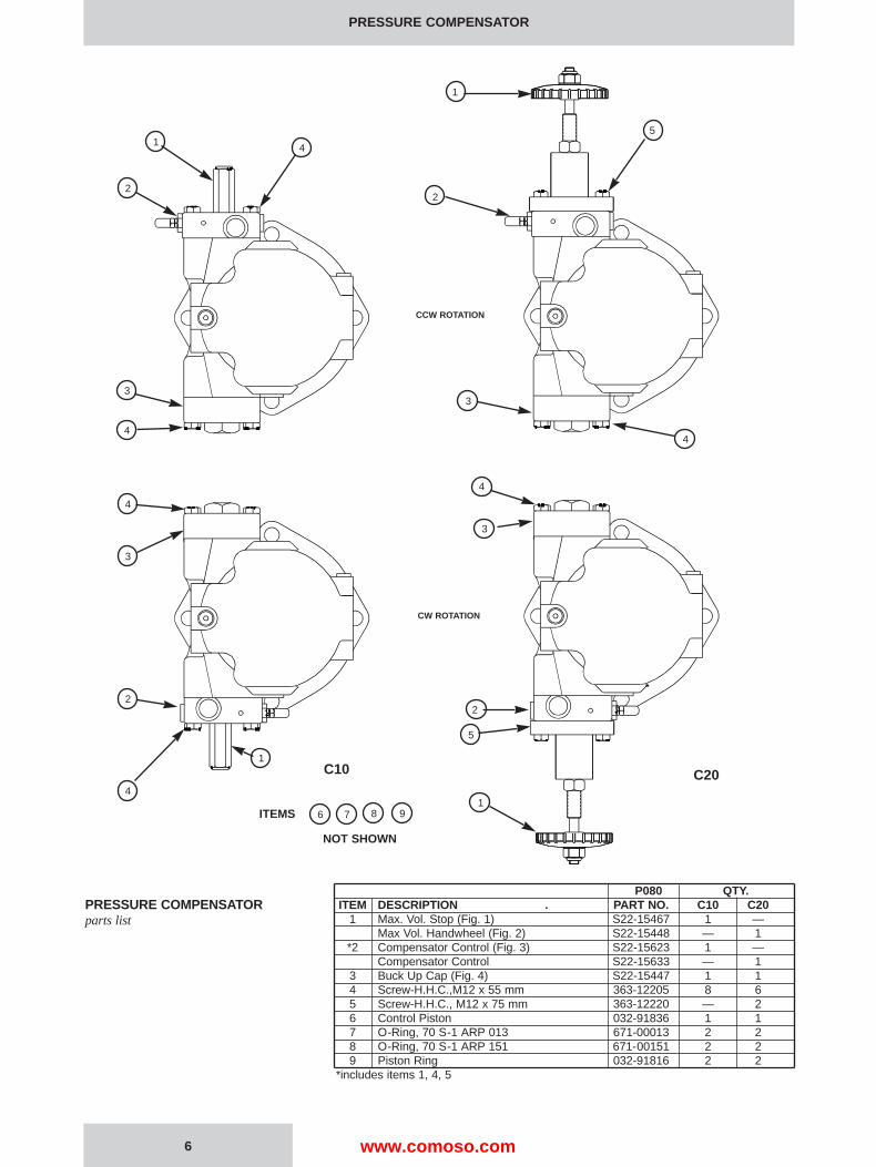
PRESSURE COMPENSATOR
P080 QTY.ITEM DESCRIPTION . PART NO. C10 C20
1 Max. Vol. Stop (Fig. 1) S22-15467 1 —Max Vol. Handwheel (Fig. 2) S22-15448 — 1
*2 Compensator Control (Fig. 3) S22-15623 1 —Compensator Control S22-15633 — 1
3 Buck Up Cap (Fig. 4) S22-15447 1 14 Screw-H.H.C.,M12 x 55 mm 363-12205 8 65 Screw-H.H.C., M12 x 75 mm 363-12220 — 26 Control Piston 032-91836 1 17 O-Ring, 70 S-1 ARP 013 671-00013 2 28 O-Ring, 70 S-1 ARP 151 671-00151 2 29 Piston Ring 032-91816 2 2
*includes items 1, 4, 5
C10 C20
PRESSURE COMPENSATORparts list
1
2
4
3
4
3
1
4
2
4
1
5
2
3
4
3
5
1
2
4
6 7 8 9ITEMS
NOT SHOWN
CCW ROTATION
CW ROTATION
www.comoso.com
PRESSURE COMPENSATOR
7
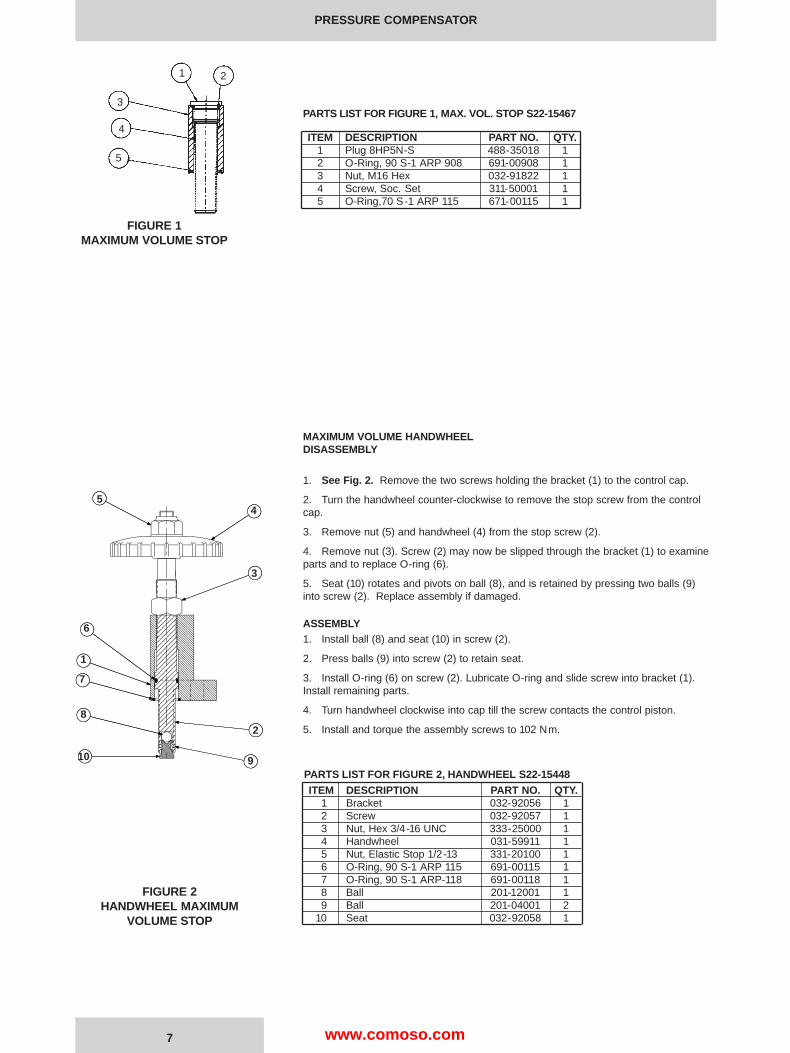
FIGURE 1MAXIMUM VOLUME STOP
PARTS LIST FOR FIGURE 1, MAX. VOL. STOP S22-15467
ITEM DESCRIPTION PART NO. QTY.1 Plug 8HP5N-S 488-35018 12 O-Ring, 90 S-1 ARP 908 691-00908 13 Nut, M16 Hex 032-91822 14 Screw, Soc. Set 311-50001 15 O-Ring,70 S-1 ARP 115 671-00115 1
MAXIMUM VOLUME HANDWHEELDISASSEMBLY
1. See Fig. 2. Remove the two screws holding the bracket (1) to the control cap.
2. Turn the handwheel counter-clockwise to remove the stop screw from the controlcap.
3. Remove nut (5) and handwheel (4) from the stop screw (2).
4. Remove nut (3). Screw (2) may now be slipped through the bracket (1) to examineparts and to replace O-ring (6).
5. Seat (10) rotates and pivots on ball (8), and is retained by pressing two balls (9)into screw (2). Replace assembly if damaged.
ASSEMBLY1. Install ball (8) and seat (10) in screw (2).
2. Press balls (9) into screw (2) to retain seat.
3. Install O-ring (6) on screw (2). Lubricate O-ring and slide screw into bracket (1).Install remaining parts.
4. Turn handwheel clockwise into cap till the screw contacts the control piston.
5. Install and torque the assembly screws to 102 Nm.
PARTS LIST FOR FIGURE 2, HANDWHEEL S22-15448
ITEM DESCRIPTION PART NO. QTY.1 Bracket 032-92056 12 Screw 032-92057 13 Nut, Hex 3/4-16 UNC 333-25000 14 Handwheel 031-59911 15 Nut, Elastic Stop 1/2-13 331-20100 16 O-Ring, 90 S-1 ARP 115 691-00115 17 O-Ring, 90 S-1 ARP-118 691-00118 18 Ball 201-12001 19 Ball 201-04001 2
10 Seat 032-92058 1
FIGURE 2HANDWHEEL MAXIMUM
VOLUME STOP
1 2
3
4
5
54
3
6
1
7
8
10
2
9
www.comoso.com

1. See Figure 3. Back off max. volume screw or handwheel to full displacement.Remove max. volume screw or handwheel assembly.
2. Remove bolts holding cap to pump.
3. Remove plug (15) and attached parts. Remove spring (11) and spool (18).
4. Remove adjusting plug (2) and attached parts. Remove seal piston (5). Note: a10-24 screw may be used to assist in pulling the piston. Remove spring (7) and cone(8).
5. Do not remove sleeve in body (1). Sleeve is pressed into cap and finished to size. Ifsleeve or cap is worn, replace the cap-sleeve assembly (1).
6. Examine seat (10) for wear. Do not remove unless damaged.
1. Install Avseal plugs (9) and orifice (19) in body.
2. Press seat (10) into bore squarely against shoulder in bore.
3. Install O-ring (14) in bottom of bore as shown. Install spool (18) into bore asshown. Install spring (11) over end of spool. Install O-ring (6) on seal piston (16). Lubri-cate and install into plug (15). Install O-ring (13) on plug (15). Install plug (15) into cap.Install screw (3) and nut (4).
4. Install O-ring (6) on seal piston (5).
5. Lubricate O-ring and install cone (8), spring (7) and seal piston into bore in cap (1),being careful that cone enters seat (10). Install remaining parts. Torque plug (12) to 60Nm. Torque plug (27) to 35 Nm. Torque plug (28) to 30 Nm.
6. Note proper location for cap on pump. Install O-rings on interface between cap andpump control pad.
7. Install cap on pump control pad, guiding the control piston into the bore. Installmaximum volume stop assembly.
8. Torque mounting bolts to 102 Nm.
Compensator is to be tested on pump. Adjust maximum volume stop to full displace-ment by backing off stop till there is no contact with the control piston.
1. Install gages on system pressure and on compensator vent ports.
2. Turn compensator adjustment screw (25) CCW until there is no contact with spring,then adjust 1/2 turn CW after contact is made with spring.
3. Turn differential adjustment screw (3) CCW until there is no contact with spring,then adjust 1/2 turn CW after contact is made with spring.
4. System relief valve should be set at 35 bar. If testing on application, apply a load topump.
5. Start prime mover. Pump should be at full displacement at 35 bar.
6. Increase system relief valve or load until compensator de-strokes pump to zero dis-placement. Set compensator to 103 bar.
7. Adjust compensator differential spool pressure to 13,8 bar. This is accomplished byadjusting the differential screw until the difference in pressure readings between the sys-tem pressure and compensator vent gages installed in the compensator cap is 13,8 bar.(It may be necessary to change differential to gain stability. Use caution when exceeding17 bar to avoid spring going solid, preventing compensator action.)
8. Set the compensator to 207 bar, 414 bar, and 500 bar.
9. At each condition, increase the system pressure until the pump fully de-strokes. Atno time should the system pressure vary more than 10,3 bar from the compensator set-ting. The control should be steady and stable at all conditions.
10. Reduce pressure to 10,3 bar below the compensator setting. Pump should return tofull stroke. Repeat two or more times. Compensator setting should be repeatable.
11. Set compensator adjustment to the required setting, or 414 Bar if not otherwisenoted. Install cap (17) on differential adjustment.
PRESSURE COMPENSATOR
COMPENSATOR DISASSEMBLY
ASSEMBLY
COMPENSATOR TEST ANDADJUSTMENT
8 www.comoso.com

PARTS LIST FOR FIGURE 3compensator C10, S22-15623compensator C20, S22-15633
ITEM DESCRIPTION PART NO. QTY.1 Cap-Sleeve Assembly S22-15604 12 Adj. Plug 032-91814 13 Soc. Setscrew 5/16-24 x 1 312-13160 14 Nut, 5/16-24 335-13100 25 Seal Piston 031-59367 16 O-Ring, 90 S-1 ARP 012 691-00012 27 Spring 032-91798 18 Cone 036-12288 19 Avseal Plug 447-00026 210 Seat 036-11692 111 Spring 033-71086 112 Plug, BSPP 1/2 447-01008 113 O-Ring, 90 S-1 ARP 910 691-00910 114 O-Ring, 90 S-1 ARP 017 691-00017 115 Plug 031-57368 116 Seal Piston 032-91305 117 Cap 449-00612 118 Spool 032-59482 119 Orifice Plug 033-25528 125 Soc. Setscrew 5/16-24 x 1-1/4 312-13180 126 Acorn Nut 036-33474 127 Plug, BSPP 3/8 447-00032 128 Plug, BSPP 1/4 447-01004 2
PRESSURE COMPENSATOR
9
FIGURE 3COMPENSATOR
COMPENSATORADJUSTMENT
DIFFERENTIALADJUSTMENT
CONTROL PRESS.PORT 1/4 BSPPTORQUE 30 Nm
COMPENSATORVENT 3/8 BSPPTORQUE 35 Nm
SYSTEM PRESSURE1/2 BSPPTORQUE 60 Nm
www.comoso.com

1. See Figure 4 Set maximum volume stop to full stroke. Remove 4 screws holdingcap to pump. Caution! Spring load could cause injury!
2. Remove cap assembly from pump.
3. Remove and examine spring (2) and piston (1). If sleeve (3) is worn, press it out andreplace.
1. Install Avseal plug (7) into cap. Press sleeve (3) into cap to shoulder. Install O-ring (5)and plug (6) into cap. Torque plug to 190 Nm. Install spring (2) and piston (1).
2. Install O-rings on interface between cap and pump control pad. Install cap assemblyon pump housing as indicated on the applicable view, guiding the control piston into thebore.
3. Torque the assembly bolts to 102 Nm.
P080ITEM DESCRIPTION PART NO. QTY.
1 Piston 032-92202 12 Spring 032-92205 13 Sleeve 032-92203 14 Control Cap 032-91832 15 O-Ring 691-00920 16 Plug 032-92204 17 Avseal Plug 447-00026 1
FIGURE 4BUCK-UP CAP
BUCK-UP CAP DISASSEMBL Y
ASSEMBLY
PARTS LIST FOR FIGURE 4P080 buck-up cap S22-15447
PRESSURE COMPENSATOR
10
1
2
3
5
76
4
TORQUE 190 Nm
www.comoso.com
11
ELECTRIC STROKER
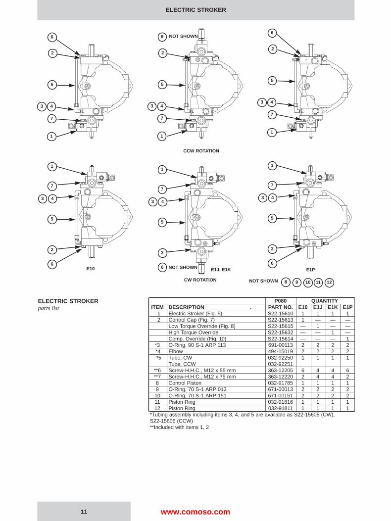
P080 QUANTITYITEM DESCRIPTION . PART NO. E10 E1J E1K E1P
1 Electric Stroker (Fig. 5) S22-15610 1 1 1 12 Control Cap (Fig. 7) S22-15613 1 — — —
Low Torque Override (Fig. 8) S22-15615 — 1 — —High Torque Override S22-15632 — — 1 —Comp. Override (Fig. 10) S22-15614 — — — 1
*3 O-Ring, 90 S-1 ARP 113 691-00113 2 2 2 2*4 Elbow 494-15019 2 2 2 2*5 Tube, CW 032-92250 1 1 1 1
Tube, CCW 032-92251**6 Screw-H.H.C., M12 x 55 mm 363-12205 6 4 4 6**7 Screw-H.H.C., M12 x 75 mm 363-12220 2 4 4 28 Control Piston 032-91785 1 1 1 19 O-Ring, 70 S-1 ARP 013 671-00013 2 2 2 2
10 O-Ring, 70 S-1 ARP 151 671-00151 2 2 2 211 Piston Ring 032-91816 1 1 1 112 Piston Ring 032-91811 1 1 1 1
*Tubing assembly including items 3, 4, and 5 are available as S22-15605 (CW),S22-15606 (CCW)**Included with items 1, 2
ELECTRIC STROKERparts list
43
7
1
2
5
6
1
7
43
5
2
6
43
7
1
2
5
6
1
7
43
5
2
6
43
7
1
2
5
6
1
7
43
5
2
6
NOT SHOWN
NOT SHOWNE10 E1J, E1K E1P
CW ROTATION
CCW ROTATION
NOT SHOWN 8 9 10 11 12
www.comoso.com
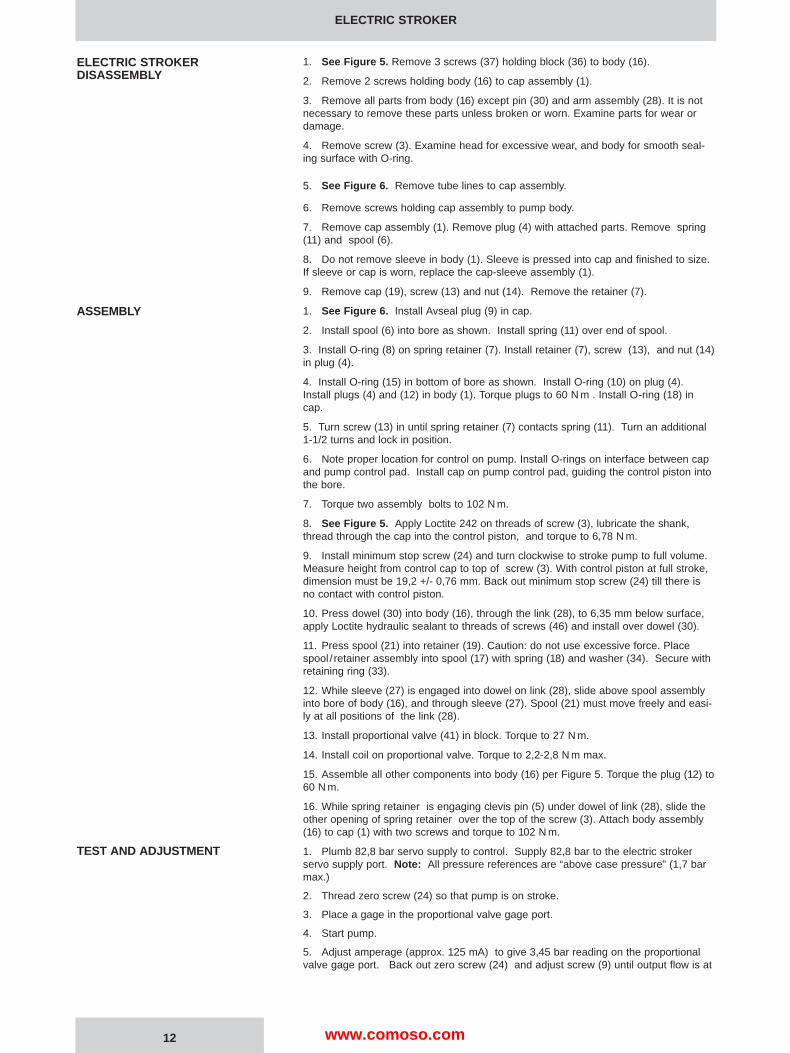
1. See Figure 5. Remove 3 screws (37) holding block (36) to body (16).
2. Remove 2 screws holding body (16) to cap assembly (1).
3. Remove all parts from body (16) except pin (30) and arm assembly (28). It is notnecessary to remove these parts unless broken or worn. Examine parts for wear ordamage.
4. Remove screw (3). Examine head for excessive wear, and body for smooth seal-ing surface with O-ring.
5. See Figure 6. Remove tube lines to cap assembly.
6. Remove screws holding cap assembly to pump body.
7. Remove cap assembly (1). Remove plug (4) with attached parts. Remove spring(11) and spool (6).
8. Do not remove sleeve in body (1). Sleeve is pressed into cap and finished to size.If sleeve or cap is worn, replace the cap-sleeve assembly (1).
9. Remove cap (19), screw (13) and nut (14). Remove the retainer (7).
1. See Figure 6. Install Avseal plug (9) in cap.
2. Install spool (6) into bore as shown. Install spring (11) over end of spool.
3. Install O-ring (8) on spring retainer (7). Install retainer (7), screw (13), and nut (14)in plug (4).
4. Install O-ring (15) in bottom of bore as shown. Install O-ring (10) on plug (4).Install plugs (4) and (12) in body (1). Torque plugs to 60 N m . Install O-ring (18) incap.
5. Turn screw (13) in until spring retainer (7) contacts spring (11). Turn an additional1-1/2 turns and lock in position.
6. Note proper location for control on pump. Install O-rings on interface between capand pump control pad. Install cap on pump control pad, guiding the control piston intothe bore.
7. Torque two assembly bolts to 102 N m.
8. See Figure 5. Apply Loctite 242 on threads of screw (3), lubricate the shank,thread through the cap into the control piston, and torque to 6,78 N m.
9. Install minimum stop screw (24) and turn clockwise to stroke pump to full volume.Measure height from control cap to top of screw (3). With control piston at full stroke,dimension must be 19,2 +/- 0,76 mm. Back out minimum stop screw (24) till there isno contact with control piston.
10. Press dowel (30) into body (16), through the link (28), to 6,35 mm below surface,apply Loctite hydraulic sealant to threads of screws (46) and install over dowel (30).
11. Press spool (21) into retainer (19). Caution: do not use excessive force. Placespool / retainer assembly into spool (17) with spring (18) and washer (34). Secure withretaining ring (33).
12. While sleeve (27) is engaged into dowel on link (28), slide above spool assemblyinto bore of body (16), and through sleeve (27). Spool (21) must move freely and easi-ly at all positions of the link (28).
13. Install proportional valve (41) in block. Torque to 27 N m.
14. Install coil on proportional valve. Torque to 2,2-2,8 N m max.
15. Assemble all other components into body (16) per Figure 5. Torque the plug (12) to60 N m.
16. While spring retainer is engaging clevis pin (5) under dowel of link (28), slide theother opening of spring retainer over the top of the screw (3). Attach body assembly(16) to cap (1) with two screws and torque to 102 N m.
1. Plumb 82,8 bar servo supply to control. Supply 82,8 bar to the electric strokerservo supply port. Note: All pressure references are “above case pressure” (1,7 barmax.)
2. Thread zero screw (24) so that pump is on stroke.
3. Place a gage in the proportional valve gage port.
4. Start pump.
5. Adjust amperage (approx. 125 mA) to give 3,45 bar reading on the proportionalvalve gage port. Back out zero screw (24) and adjust screw (9) until output flow is at
ELECTRIC STROKER
ELECTRIC STROKERDISASSEMBLY
ASSEMBLY
TEST AND ADJUSTMENT
12 www.comoso.com
zero stroke position. Lock both adjustments in place.
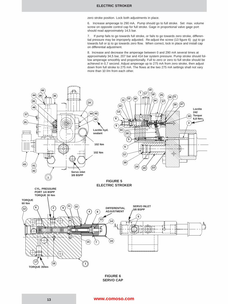
6. Increase amperage to 290 mA. Pump should go to full stroke. Set max. volumescrew on opposite control cap for full stroke. Gage in proportional valve gage portshould read approximately 14,5 bar.
7. If pump fails to go towards full stroke, or fails to go towards zero stroke, differen-tial pressure may be improperly adjusted. Re-adjust the screw (13 figure 6) out to gotowards full or in to go towards zero flow. When correct, lock in place and install capon differential adjustment.
8. Increase and decrease the amperage between 0 and 290 mA several times atapproximately 34,5 bar, 207 bar and 414 bar system pressure. Pump stroke should fol-low amperage smoothly and proportionally. Full to zero or zero to full stroke should beachieved in 0,7 second. Adjust amperage up to 275 mA from zero stroke, then adjustdown from full stroke to 275 mA. The flows at the two 275 mA settings shall not varymore than 10 l/m from each other.
ELECTRIC STROKER
13
FIGURE 5ELECTRIC STROKER
FIGURE 6SERVO CAP
48
3638
16
46
102 Nm
1
42
4143
35
37
17
8
9
3328
5
6
12
39
24 20 23
3
14
46
35
10
1115 39
719
18 25
34 27
26 21
29 47
102 Nm
44 4530
44
12 6
4 8
1314
5
19715
11817
2 911 10
Loctite242Torque6,8 Nm
Loctite hyd.sealant
DIFFERENTIALADJUSTMENT
SERVO INLET3/8 BSPP
CYL. PRESSUREPORT 1/4 BSPPTORQUE 30 Nm
TORQUE 35Nm
TORQUE60 Nm
Servo inlet3/8 BSPP
www.comoso.com
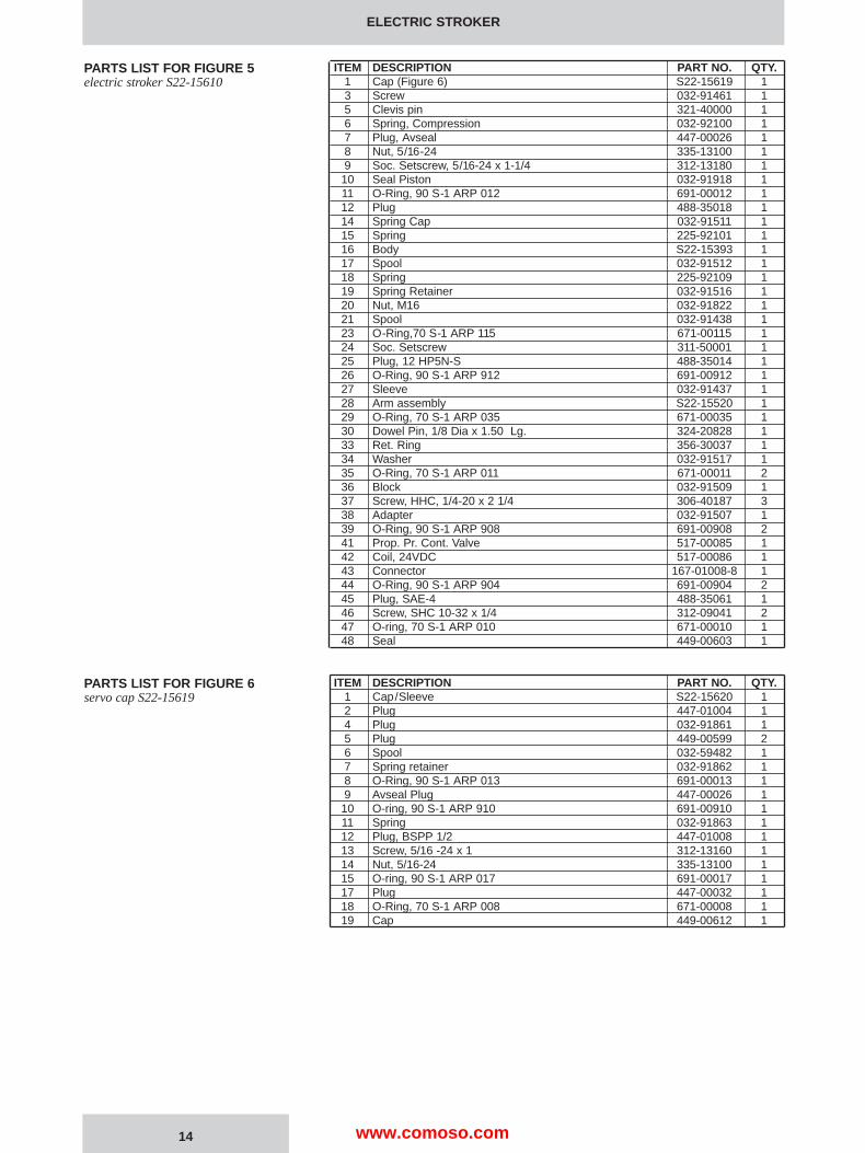
ITEM DESCRIPTION PART NO. QTY.1 Cap (Figure 6) S22-15619 13 Screw 032-91461 15 Clevis pin 321-40000 16 Spring, Compression 032-92100 17 Plug, Avseal 447-00026 18 Nut, 5/16-24 335-13100 19 Soc. Setscrew, 5/16-24 x 1-1/4 312-13180 110 Seal Piston 032-91918 111 O-Ring, 90 S-1 ARP 012 691-00012 112 Plug 488-35018 114 Spring Cap 032-91511 115 Spring 225-92101 116 Body S22-15393 117 Spool 032-91512 118 Spring 225-92109 119 Spring Retainer 032-91516 120 Nut, M16 032-91822 121 Spool 032-91438 123 O-Ring,70 S-1 ARP 115 671-00115 124 Soc. Setscrew 311-50001 125 Plug, 12 HP5N-S 488-35014 126 O-Ring, 90 S-1 ARP 912 691-00912 127 Sleeve 032-91437 128 Arm assembly S22-15520 129 O-Ring, 70 S-1 ARP 035 671-00035 130 Dowel Pin, 1/8 Dia x 1.50 Lg. 324-20828 133 Ret. Ring 356-30037 134 Washer 032-91517 135 O-Ring, 70 S-1 ARP 011 671-00011 236 Block 032-91509 137 Screw, HHC, 1/4-20 x 2 1/4 306-40187 338 Adapter 032-91507 139 O-Ring, 90 S-1 ARP 908 691-00908 241 Prop. Pr. Cont. Valve 517-00085 142 Coil, 24VDC 517-00086 143 Connector 167-01008-8 144 O-Ring, 90 S-1 ARP 904 691-00904 245 Plug, SAE-4 488-35061 146 Screw, SHC 10-32 x 1/4 312-09041 247 O-ring, 70 S-1 ARP 010 671-00010 148 Seal 449-00603 1
ITEM DESCRIPTION PART NO. QTY.1 Cap/Sleeve S22-15620 12 Plug 447-01004 14 Plug 032-91861 15 Plug 449-00599 26 Spool 032-59482 17 Spring retainer 032-91862 18 O-Ring, 90 S-1 ARP 013 691-00013 19 Avseal Plug 447-00026 110 O-ring, 90 S-1 ARP 910 691-00910 111 Spring 032-91863 112 Plug, BSPP 1/2 447-01008 113 Screw, 5/16 -24 x 1 312-13160 114 Nut, 5/16-24 335-13100 115 O-ring, 90 S-1 ARP 017 691-00017 117 Plug 447-00032 118 O-Ring, 70 S-1 ARP 008 671-00008 119 Cap 449-00612 1
ELECTRIC STROKER
PARTS LIST FOR FIGURE 5electric stroker S22-15610
PARTS LIST FOR FIGURE 6servo cap S22-15619
14 www.comoso.com

ELECTRIC STROKER
CONTROL CAP DISASSEMBL Y
ASSEMBLY
PARTS LIST FOR FIGURE 7control cap assembly S22-15613
15
FIGURE 7CONTROL CAP ASSEMBL Y
ITEM DESCRIPTION PART NO. QTY.1 Control Cap 032-92229 12 Plug 449-00599 13 O-ring, 70 S-1 ARP 115 671-00115 14 Screw, M16 -2 x 80 311-50001 15 Nut 032-91822 16 Plug 488-35018 17 O-ring 90 S-1 ARP 908 691-00908 1
1. See Figure 7. Remove cover (5) and Max. volume screw (4).
2. Remove 4 screws holding cap to pump.
3. Remove cap assembly from pump.
1. Install O-rings on interface between cap and pump control pad. Install cap on pumphousing as indicated on the applicable view, guiding the control piston into the bore.
2. Torque the assembly bolts to 102 Nm.
3. Install screw (4) in cap. Install O-ring (3) on nut (5). Install nut (5) on screw.
3. Adjust screw till pump is slightly on stroke and lock nut (5).
4. Install O-ring (7) on plug (6). Install plug in nut (5). Torque plug (6) to 68 Nm.
TORQUE68 Nm
www.comoso.com
1. See figure 8. Remove 2 screws holding torque limiter body (16) to cap assembly(1).
2. Remove all parts from torque limiter body (16) except pin (30) and arm assembly(28). It is not necessary to remove these parts unless broken or worn. Examine partsfor wear or damage.
3. Remove screw (3). Examine head for excessive wear, and body for smooth sealingsurface with O-ring.
4. Remove maximum volume stop assembly (items 11, 13, 14, 20 and 24).
5. Remove cap assembly (1).
6. See fig. 9. Remove plug (15) and attached parts. Remove spring (11) and spool(18).
7. Remove adjusting plug (2) and attached parts. Remove seal piston (5). Note: a 10-24 screw may be attached to assist in pulling the piston. Remove spring (7) and cone(8).
8. Do not remove sleeve in body (1). Sleeve is pressed into cap and finished to size. Ifsleeve, snout or cap is worn, replace the cap-sleeve assembly (1).
9. Examine seat (10) for wear. Do not remove unless damaged.
1. See figure 9. Install Avseal plugs (9) and orifice (19).
2. Press seat (10) into bore squarely against shoulder in bore.
3. Install spool (18) into bore as shown. Install spring (11) over end of spool. Install O-ring (6) on seal piston (16). Lubricate and install into plug (15). Install O-ring (14) inbottom of bore as shown. Install O-ring (13) on plug (15). Install plug (15) into cap.Install screw (3) and nut (4).
4. Install O-ring (6) on seal piston (5).
5. Lubricate O-ring and install cone (8), spring (7) and seal piston into bore in cap (1),being careful that cone enters seat (10). Install adj. plug (2), screw (25), nut (4), andacorn nut (26).
6. Install plug (12) and torque to 60 Nm. Install plug (21). Torque to 35 Nm.
7. Carefully install O-ring (30) into the cap.
8. Note proper location for cap. Install O-rings on interface between cap and pumpcontrol pad. Install cap assembly on pump, guiding the control piston into the bore.Torque two mounting screws to 102 Nm.
9. See figure 8. Install maximum stop screw (24), cover (20) ,O-ring (14) and plug(11) with O-ring (13).
10. Apply Loctite 242 on threads of screw (3), lubricate the shank, thread through thecap into the control piston, and torque to 6,78 Nm.
11. Measure height from control cap to top of screw. With control piston at zero stroke,dimension must be 19,2 +/- 0,76 mm.
12. Press dowel (30) into body (16), through the link assembly (28), to 6,35 mm belowsurface. Apply Loctite hydraulic sealant® to threads of screws (33) and install overdowel (30).
13. While sleeve (27) is engaged into dowel on link (28), slide spool (21) into bore ofbody (16), and through sleeve (27). Spool (21) must move freely and easily at all posi-tions of the link (28).
14. Assemble remaining parts per drawing. Torque plugs (11) to 68 Nm.
15. While spring retainer is engaging clevis pin (5) under dowel of link (28), slide theother opening of spring retainer over the top of the screw (3). Attach body assembly(16) to cap (1) and torque assembly screws to 102 Nm.
TORQUE LIMITER OVERRIDE
TORQUE LIMITER OVERRIDEDISASSEMBLY
ASSEMBLY
16www.comoso.com
TORQUE LIMITER OVERRIDE
17
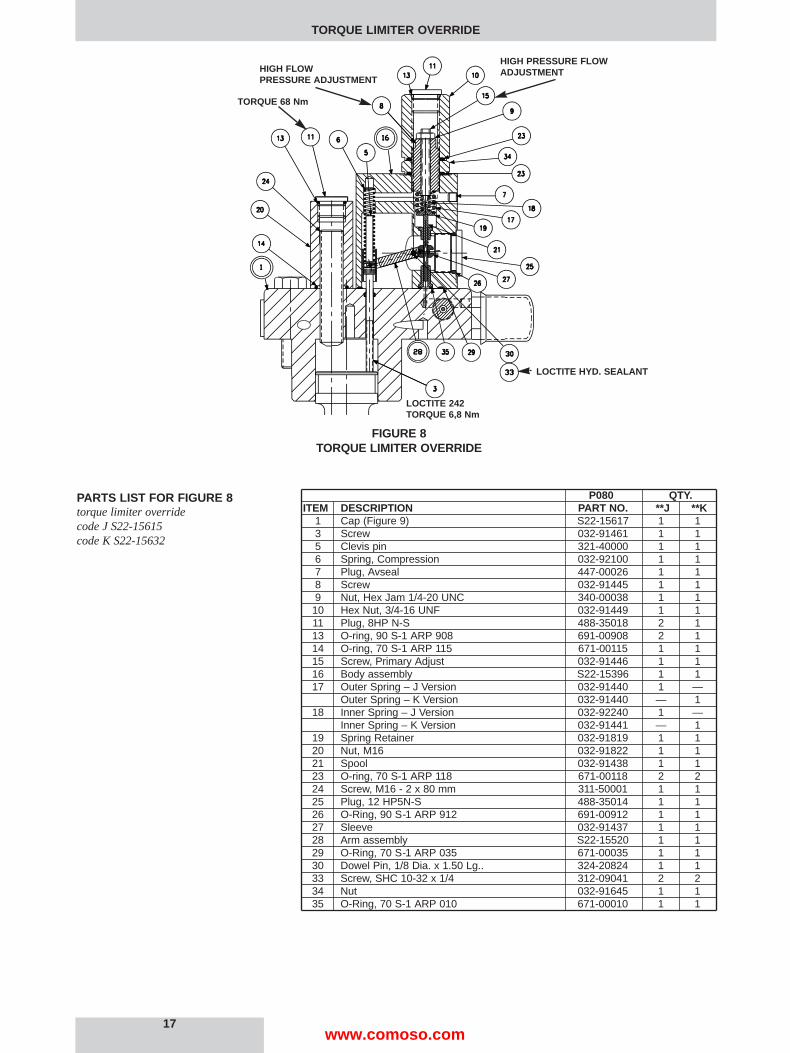
FIGURE 8TORQUE LIMITER OVERRIDE
P080 QTY.ITEM DESCRIPTION PART NO. **J **K
1 Cap (Figure 9) S22-15617 1 13 Screw 032-91461 1 15 Clevis pin 321-40000 1 16 Spring, Compression 032-92100 1 17 Plug, Avseal 447-00026 1 18 Screw 032-91445 1 19 Nut, Hex Jam 1/4-20 UNC 340-00038 1 110 Hex Nut, 3/4-16 UNF 032-91449 1 111 Plug, 8HP N-S 488-35018 2 113 O-ring, 90 S-1 ARP 908 691-00908 2 114 O-ring, 70 S-1 ARP 115 671-00115 1 115 Screw, Primary Adjust 032-91446 1 116 Body assembly S22-15396 1 117 Outer Spring – J Version 032-91440 1 —
Outer Spring – K Version 032-91440 — 118 Inner Spring – J Version 032-92240 1 —
Inner Spring – K Version 032-91441 — 119 Spring Retainer 032-91819 1 120 Nut, M16 032-91822 1 121 Spool 032-91438 1 123 O-ring, 70 S-1 ARP 118 671-00118 2 224 Screw, M16 - 2 x 80 mm 311-50001 1 125 Plug, 12 HP5N-S 488-35014 1 126 O-Ring, 90 S-1 ARP 912 691-00912 1 127 Sleeve 032-91437 1 128 Arm assembly S22-15520 1 129 O-Ring, 70 S-1 ARP 035 671-00035 1 130 Dowel Pin, 1/8 Dia. x 1.50 Lg.. 324-20824 1 133 Screw, SHC 10-32 x 1/4 312-09041 2 234 Nut 032-91645 1 135 O-Ring, 70 S-1 ARP 010 671-00010 1 1
PARTS LIST FOR FIGURE 8torque limiter overridecode J S22-15615code K S22-15632
HIGH PRESSURE FLOWADJUSTMENTHIGH FLOW
PRESSURE ADJUSTMENT
TORQUE 68 Nm
LOCTITE HYD. SEALANT
LOCTITE 242TORQUE 6,8 Nm
www.comoso.com

ITEM DESCRIPTION PART NO. QTY.1 Cap-Sleeve Assembly S22-15618 12 Adj. Plug 032-91814 13 Soc. Setscrew 5/16-24 x 1 312-13160 14 Nut, 5/16-24 335-13100 25 Seal Piston 031-59367 16 0-Ring, 90 S-1 ARP 012 691-00012 27 Spring 032-91798 18 Cone 036-12288 19 Avseal Plug 447-00026 210 Seat 036-11692 111 Spring 033-71086 112 Plug, BSPP 1/2 447-01008 113 O-Ring, 90 S-1 ARP 910 691-00910 114 O-Ring, 90 S-1 ARP 017 691-00017 115 Plug 031-57368 116 Seal Piston 032-91305 117 Cap 449-00612 118 Spool 032-91820 119 Orifice 036-12819 121 Plug 447-00032 125 Soc. Setscrew 5/16-24 x 1-1/4 312-13180 126 Nut, Acorn 036-33474 127 Plug 449-00599 128 Plug, 1/4 BSPP 447-01004 230 O-ring, 70 S-1 ARP 008 671-00008 1
TORQUE LIMITER OVERRIDE
PARTS LIST FOR FIGURE 9,torque limiter override cap S22-15617
18
FIGURE 9TORQUE LIMITER OVERRIDE CAP
DIFFERENTIAL ADJUSTMENT
CYLINDER PRESSURE PORT1/4 BSPPTORQUE 30 Nm
SYSTEM PRESSURE1/2 BSPPTORQUE 60 Nm
COMPENSATOR ADJUSTMENT
www.comoso.com

1. Install gages on system pressure and on compensator vent ports.
2. Turn compensator adjustment screw out to remove spring load, then 1/2 turn in.
3. Turn differential adjustment screw out to remove spring load, then 1/2 turn in.
4. Back out maximum volume stop to full volume.
5. For setting and testing compensator override function, disable torque limiter in thismanner: Back out primary adjusting screw (15) figure 8, to remove all load. Turn in outeradjusting screw (8) to go solid. Caution! do not apply over 1,2 Nm torque to avoid damageto internal parts!
6. Start prime mover with system relief set at 35 bar.
7. Stroke pump to full displacement. Apply a load to the pump.
8. Increase system relief valve until compensator de-strokes pump to zero displace-ment. Set compensator to 103 bar.
9. Adjust compensator differential spool pressure to 13,8 bar. This is accomplished byadjusting the differential screw until the difference in pressure readings between the sys-tem pressure and compensator vent gages installed in the compensator cap is 13,8 bar.(It may be necessary to change differential to gain stability. Use caution when exceeding17 bar to avoid spring going solid, preventing compensator action.) When correct, lock inplace and install cap.on differential adjustment.
10. Set the compensator to 207 bar, 414 bar, and 500 bar. At each condition, increasethe system pressure until the pump fully de-strokes. At no time should the system pres-sure vary more than 10,3 bar from the compensator setting. The control should be steadyand stable at all conditions.
11. Reduce pressure to 10,3 bar below the compensator setting. Pump should return tofull stroke. Repeat two or more times. Compensator setting should be repeatable.
12. Set compensator adjustment to at least 34,5 bar above the required setting, or 483bar.
Set the torque limiter by using the formula:
kW = P•Q/(Eff. • 600)where P = pressure in Bar
Q = flow in l/m
calculate these two values:a. System pressure at full pump flow.b. Pump flow at full system pressure.
13. Set system relief valve to pressure (a) calculated above. Back out primary adjustingscrew to remove all load. Set outer adjusting screw (8) so that pump just commences tode-stroke.
14. Set the system relief valve to the required maximum system pressure. Set primaryadjusting screw (15) to obtain the calculated flow (b) at full system pressure.
15. Set compensator adjustment to the required setting, or 414 bar if not otherwise noted.
Note: Electric motor current may be used instead of calculated flows to set power. In step13, set the outer adjusting screw (8) to achieve the rated motor current. In step 14, setthe adjustment (15) to achieve the rated motor current.
TORQUE LIMITER OVERRIDE
TORQUE LIMITER OVERRIDETEST AND ADJUSTMENT
19www.comoso.com

1. See Figure 10. Remove tube line to cap.
2. Remove maximum volume stop assembly (items 20, 21, 22, 23, 24).
3. Remove cap assembly.
4. Remove plug (15) and attached parts. Remove spring (11) and spool (18).
5. Remove adj. plug (2) and attached parts. Remove seal piston (5). Note: a 10-24screw may be attached to assist in pulling the piston. Remove spring (7) and cone (8).
6. Do not remove sleeve in body (1). Sleeve is pressed into cap and finished to size. Ifsleeve, snout or cap is worn, replace the cap-sleeve assembly (1).
7. Examine seat (10) for wear. Do not remove unless damaged.
1. Install Avseal plugs (9) in body. Install orifice (19) in body.
2. Press seat (10) into bore to shoulder in bore.
3. Install spool (18) into bore as shown. Install spring (11) over end of spool. Install O-ring (6) on seal piston (16). Lubricate and install into plug (15). Install O-ring (14) inbottom of bore as shown. Install O-ring (13) on plug (15). Install plug (15) into cap.Install screw (3) and nut (4).
4. Install O-ring (6) on seal piston (5).
5. Lubricate O-ring and install cone (8), spring (7) and seal piston into bore in cap (1),being careful that cone enters seat (10).
6. Install remaining parts. Torque plug (12) to 60 Nm. Torque plug (31) to 35 Nm.Torque plug (28) to 30 Nm.
7. Note proper location for cap on pump. Install O-rings on interface between cap andpump control pad.
8. Install cap assembly on pump, guiding the control piston into the bore.
9. Torque mounting bolts to 102 Nm.
10. Install tube fitting and tube line connecting to opposite cap.
Compensator is to be tested on pump. Adjust maximum volume stop to full displace-ment.
1. Install gages on system pressure and on compensator vent ports.
2. Turn compensator adjustment screw (25) CCW until there is no contact with spring,then adjust 1/2 turn CW after contact is made with spring.
3. Turn differential adjustment screw (3) CCW until there is no contact with spring,then adjust 1/2 turn CW after contact is made with spring.
4. Start prime mover with system relief valve set at 35 bar. Apply a load to the pump.
5. Set pump control to full displacement. Pump should go to full displacement at 35bar.
6. Increase system relief valve until compensator de-strokes pump to zero displace-ment. Set compensator to 100 bar.
7. Adjust compensator differential spool pressure to 13,8 bar. This is accomplished byadjusting the differential screw until the difference in pressure readings between the sys-tem pressure and compensator vent gages installed in the compensator cap is 13,8 bar.(It may be necessary to change differential to gain stability. Use caution when exceeding17 bar to avoid spring going solid, preventing compensator action.) When correct, lockin place and install cap.on differential adjustment.
8. Set the compensator to 207 bar, 414 bar, and 500 bar.
9. At each condition, increase the system pressure until the pump fully de-strokes. Atno time should the system pressure vary more than 10,3 bar from the compensator set-ting. The control should be steady and stable at all conditions.
10. Reduce pressure to 10,3 bar below the compensator setting. Pump should return tofull stroke. Repeat two or more times. Compensator setting should be repeatable.
11. Set compensator adjustment to the required setting, or 414 bar if not otherwisenoted.
COMPENSATOR OVERRIDE
COMPENSATOR OVERRIDEDISASSEMBLY
ASSEMBLY
TEST AND ADJUSTMENT
20www.comoso.com
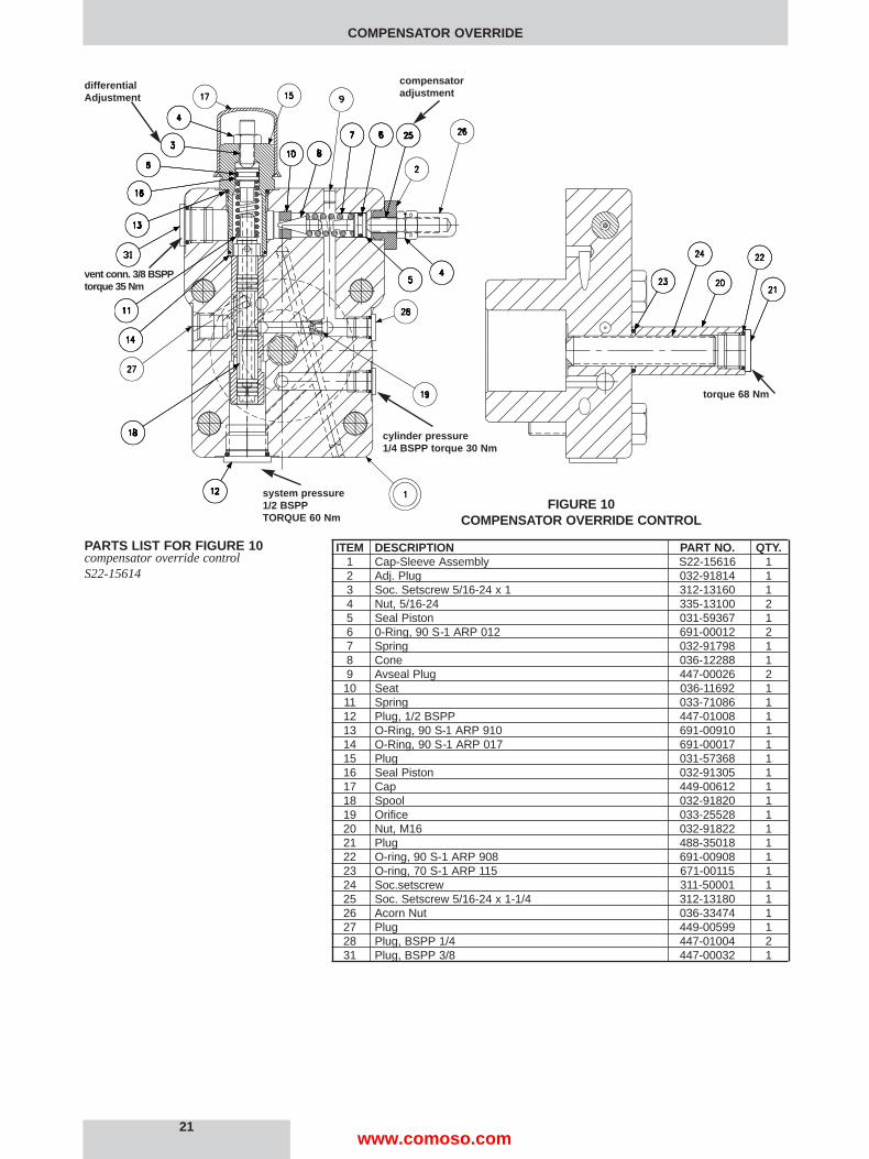
ITEM DESCRIPTION PART NO. QTY.1 Cap-Sleeve Assembly S22-15616 12 Adj. Plug 032-91814 13 Soc. Setscrew 5/16-24 x 1 312-13160 14 Nut, 5/16-24 335-13100 25 Seal Piston 031-59367 16 0-Ring, 90 S-1 ARP 012 691-00012 27 Spring 032-91798 18 Cone 036-12288 19 Avseal Plug 447-00026 210 Seat 036-11692 111 Spring 033-71086 112 Plug, 1/2 BSPP 447-01008 113 O-Ring, 90 S-1 ARP 910 691-00910 114 O-Ring, 90 S-1 ARP 017 691-00017 115 Plug 031-57368 116 Seal Piston 032-91305 117 Cap 449-00612 118 Spool 032-91820 119 Orifice 033-25528 120 Nut, M16 032-91822 121 Plug 488-35018 122 O-ring, 90 S-1 ARP 908 691-00908 123 O-ring, 70 S-1 ARP 115 671-00115 124 Soc.setscrew 311-50001 125 Soc. Setscrew 5/16-24 x 1-1/4 312-13180 126 Acorn Nut 036-33474 127 Plug 449-00599 128 Plug, BSPP 1/4 447-01004 231 Plug, BSPP 3/8 447-00032 1
COMPENSATOR OVERRIDE
PARTS LIST FOR FIGURE 10compensator override controlS22-15614
21
FIGURE 10COMPENSATOR OVERRIDE CONTROL
compensatoradjustment
cylinder pressure1/4 BSPP torque 30 Nm
system pressure1/2 BSPPTORQUE 60 Nm
differentialAdjustment
vent conn. 3/8 BSPPtorque 35 Nm
torque 68 Nm
www.comoso.com

22
HYDRAULIC STROKER
HYDRAULIC STROKERparts list
P080 QUANTITYITEM DESCRIPTION PART NO. H10 H1J H1K H1P
1 Hydraulic Stroker (Fig. 11) S22-15611 1 1 1 12 Control Cap (Fig. 7) S22-15613 1 — — —
Low Torque Override (Fig. 8) S22-15615 — 1 — —High Torque Override S22-15632 — — 1 —Comp. Override (Fig. 10) S22-15614 — — — 1
*3 O-Ring, 90 S-1 ARP 113 691-00113 2 2 2 2*4 Elbow 494-15019 2 2 2 2*5 Tube, CW 032-92250 1 1 1 1
Tube, CCW 032-92251**6 Screw-H.H.C., M12 x 55 mm 363-12205 6 4 4 6**7 Screw-H.H.C., M12 x 75 mm 363-12220 2 4 4 28 Control Piston 032-91785 1 1 1 19 O-Ring, 70 S-1 ARP 013 671-00013 2 2 2 210 O-Ring, 70 S-1 ARP 151 671-00151 2 2 2 211 Piston Ring 032-91816 1 1 1 112 Piston Ring 032-91811 1 1 1 1
*Tubing assembly including items 3, 4, and 5 are available as S22-15605 (CW),S22-15606 (CCW)**Included with items 1, 2
43
7
1
2
5
6
1
7
43
5
2
6
43
7
1
2
5
6
1
7
43
5
2
6
43
7
1
2
5
6
1
7
43
5
2
6NOT SHOWN
NOT SHOWN
NOT SHOWN 8 9 10 11 12
H10 H1J, H1K H1P
CW ROTATION
CCW ROTATION
7
www.comoso.com

1. See figure 1 1. Remove 2 screws holding body (16) to cap assembly (1).
2. Remove all parts from body (16) except pin (30) and arm assembly (28). It is notnecessary to remove these parts unless broken or worn. Examine parts for wear ordamage.
3. Remove screw (3). Examine head for excessive wear, and body for smooth sealingsurface with O-ring.
4. See figure 6. Remove tube lines to cap assembly.
5. Remove screws holding cap assembly to pump body.
6. Remove cap assembly (1). Remove plug (4) with attached parts. Remove spring(11) and spool (6).
7. Do not remove sleeve in body (1). Sleeve is pressed into cap and finished to size. Ifsleeve or cap is worn, replace the cap-sleeve assembly (1).
8. Remove screw (13) and nut (14). Remove the retainer (7).
1. See figure 6. Install Avseal plug (9) in cap.
2. Install spool (6) into bore as shown. Install spring (11) over end of spool.
3. Install O-ring (8) on spring retainer (7). Install retainer (7), screw (13), and nut (14)in plug (4).
4. Install O-ring (15) in bottom of bore as shown. Install O-ring (10) on plug (4). Installplugs (4) and (12) in body (1). Torque plugs to 60 Nm . Install O-ring (18) in cap.
5. Turn screw (13) in until spring retainer (17) contacts spring (11). Turn an additional1-1/2 turns and lock in position.
6. Note proper location for control on pump. Install O-rings on interface between capand pump control pad. Install cap on pump control pad, guiding the control piston intothe bore.
7. Torque two assembly bolts to 102 Nm.
8. See figure 1 1. Apply Loctite 242 on threads of screw (3), lubricate the shank,thread through the cap into the control piston, and torque to 6,78 Nm.
9. Install minimum stop screw (24) and turn clockwise to stroke pump to full volume.Measure height from control cap to top of screw (3). With control piston at full stroke,dimension must be 19,2 +/- 0,76 mm. Back out minimum stop screw (24) till there is nocontact with control piston.
10. Press dowel (30) into body (16), through the link (28), to 6,35 mm below surface.Apply Loctite hydraulic sealant to threads of screws (40) and install over dowel (30).
11. Press spool (21) into retainer (19). Caution: do not use excessive force. Placespool/ retainer assembly into spool (17) with spring (18) and washer (34). Secure withretaining ring (33).
12. While sleeve (27) is engaged into dowel on link (28), slide above spool assemblyinto bore of body (16), and through sleeve (27). Spool (21) must move freely and easilyat all positions of the link (28).
13. Assemble all other components into body (16) per figure 11. Torque plug (12) to 68Nm.
14. While spring retainer is engaging clevis pin (5) under dowel of link (28), slide theother opening of spring retainer over the top of the screw (3). Attach body assembly(16) to cap (1) with two screws and torque to 102 Nm.
1. Plumb 82,8 bar servo supply to control.
2. Thread zero screw (24) so that pump is on stroke.
3. Start pump.
4. Supply 20 bar to hydraulic stroker control port.
5. Adjust screw (9) until output flow is at the full stroke position. Lock in place.
6. Reduce control pressure to 0 bar. Back out zero screw (24) until pump is at zerostroke. Lock in place.
7. Increase and decrease control pressure between 0 and 20 bar several times atapproximately 34,5 bar, 207 bar, and 414 bar system pressure. Pump stroke should fol-low control pressure smoothly and proportionally. Full to zero or zero to full strokeshould be achieved in no more than .7 second. Full stroke should be achieved at 14,5bar. Zero stroke should be achieved at 3,45 +/- 1 bar. Adjust control pressure up to12 bar from zero stroke, then adjust down from full stroke to 12 bar. The flows at thetwo settings shall not vary more than 10 l/m from each other. When all adjustments arecorrect, lock in place and install cap.on differential adjustment.
HYDRAULIC STROKER
HYDRAULIC STROKERDISASSEMBLY
ASSEMBLY
TEST AND ADJUSTMENT
23www.comoso.com

24
HYDRAULIC STROKER
ITEM DESCRIPTION PART NO. QTY.1 Cap (Figure 6) S22-15619 13 Screw 032-91461 15 Clevis pin 321-40000 16 Spring, Compression 032-92100 17 Plug, Avseal 447-00026 18 Nut, 5/16-24 335-13100 19 Soc. Setscrew, 5/16-24 x 1-1/4 312-13180 110 Seal Piston 032-91918 111 O-Ring, 90 S-1 ARP 012 691-00012 112 Plug, 8 HP5N-S 488-35018 114 Spring Cap 032-91511 115 Spring 225-92101 116 Body S22-15393 117 Spool 032-91512 118 Spring 225-92109 119 Spring Retainer 032-91516 120 Nut, M16 032-91822 121 Spool 032-91438 123 O-Ring,70 S-1 ARP 115 671-00115 124 Soc. Setscrew, M16 - 2 x 80 mm 311-50001 125 Plug, 12 HP5N-S 488-35014 126 O-Ring, 90 S-1 ARP 912 691-00912 127 Sleeve 032-91437 128 Arm assembly S22-15520 129 O-Ring, 70 S-1 ARP 035 671-00035 130 Dowel Pin, 1/8 Dia x 1.50 Lg. 324-20824 133 Ret. Ring 356-30037 134 Washer 032-91517 135 O-Ring, 70 S-1 ARP 011 671-00011 236 Plate 032-91510 137 Screw, HHC,1/4-20 x 3/4 306-40142 338 Adapter 032-91507 139 O-Ring, 90 S-1 ARP 908 691-00908 140 Screw, SHC 10-32 x 1/4 312-09041 244 O-ring, 90 S-1 ARP 904 691-00904 145 O-ring, 70 S-1 ARP 010 671-00010 148 Seal 449-00603 1
PARTS LIST FOR FIGURE 11hydraulic stroker S22-15611
FIGURE 11HYDRAULIC STROKER
LOCTITETORQUE 102 Nm
TORQUE 102 Nm
SERVO SUPPLY3/8 BSPP
CONTROL SIGNALINLET 1/4 BSPP
CYL. PRESS.1/4 BSPP
LOCTITE 242TORQUE 6,8Nm
TORQUE68 Nm
www.comoso.com

25
TORQUE LIMITER
P080 QUANTITYITEM DESCRIPTION PART NO. J10 K10 J20 K20
1 Max. Vol. Stop (Fig. 1) S22-15467 1 1 — —Max Vol. Handwheel (Fig. 2) S22-15448 — — 1 1
*2 Low Torque Limiter (Fig. 12) S22-15624 1 — — —High Torque Limiter S22-15631 — 1 — —Low Torque Limiter S22-15634 — — 1 —High Torque Limiter S22-15636 — — — 1
3 Buck Up Cap (Fig. 4) S22-15447 1 1 1 14 Screw-H.H.C., M12 x 55 mm 363-12205 6 6 4 45 Screw-H.H.C., M12 x 75 mm 363-12220 2 2 4 46 Control Piston 032-91836 1 1 1 17 O-Ring, 70 S-1 ARP 013 671-00013 2 2 2 28 O-Ring, 70 S-1 ARP 151 671-00151 2 2 2 29 Piston ring 032-91816 2 2 2 2
*Includes items 1, 4, 5
TORQUE LIMITERPARTS LISTtorque limiter
CCW ROTATION
CW ROTATION
J/K10 J/K20
1
2
5
3
4
3
5
2
4
1
5
2
3
4
3
5
1
2
4
6 7 8 9ITEMS
NOT SHOWN
NOT SHOWN
NOT SHOWN1
www.comoso.com
1. See Figure 12. Remove 2 screws holding torque limiter body (16) to cap assembly(1).
2. Remove all parts from torque limiter body (16) except pin (30) and arm assembly(28). It is not necessary to remove these parts unless broken or worn. Examine parts forwear or damage.
3. Remove screw (3). Examine head for excessive wear, and body for smooth sealingsurface with O-ring.
4. Remove maximum stop handwheel assembly or maximum stop screw assembly.
5. Remove cap assembly (1).
6. See Figure 13 Remove plug (15) and attached parts. Remove spring (11) and spool(18).
7. Remove adjusting plug (2) and attached parts. Remove spring (7) and cone (8).
8. Do not remove sleeve in body (1). Sleeve is pressed into cap and finished to size. Ifsleeve or cap is worn, replace the cap-sleeve assembly (1).
9. Examine seat (10) for wear. Do not remove unless damaged.
1. See Figure 13 Install Avseal plugs (9) and orifice (19) in body.
2. Press seat (10) into bore squarely against shoulder in bore.
3. Install spool (18) into bore as shown. Install spring (11) over end of spool. Install O-ring (6) on seal piston (16). Lubricate and install into plug (15). Install O-ring (14) in bot-tom of bore as shown. Install O-ring (13) on plug (15). Install plug (15) into cap. Installscrew (3) and nut (4). Install plug (12). Torque plugs (12) and (15) to 60 Nm. Install plug(21). Torque to 35 Nm. Install plug (28). Torque to 30 Nm.
4. Install O-ring (6) on seal piston (5). Lubricate O-ring and Install cone (8), spring (7)and seal piston (5) into bore in cap (1), being careful that cone enters seat (10). Installadj. plug (2), screw (25), nut (4) and acorn nut (26).
5. Carefully install O-ring (27) in the cap.
6. Note proper location for control cap. Install O-rings on interface between cap andpump control pad. Install cap, guiding control piston into bore.
7. Install maximum volume handwheel or screw assembly. Set stop to clear control pis-ton. Install two mounting screws and torque to 102 Nm.
8. See Figure 12. Apply Loctite 242 on threads of screw (3), lubricate the shank,thread through the cap into the control piston, and torque to 6,78 Nm
9. Measure height from control cap to top of screw. With control piston at full stroke,dimension must be 38,1 +/- .76 mm.
10. Press dowel (30) into body (16), through the link assembly (28), to 6,35 mm belowsurface. Apply Loctite hydraulic sealant to threads of screws (35) and install over dowel(30).
11. While sleeve (27) is engaged into dowel on link (28), slide spool (21) into bore ofbody (16), and through sleeve (27). Spool (21) must move freely and easily at all posi-tions of the link (28).
12. Assemble remaining parts per drawing. While spring retainer is engaging clevis pin(5) under dowel of link (28), slide the other opening of spring retainer over the top of thescrew (3). Attach body assembly (16) to cap (1) and torque screws to 102 Nm.
TORQUE LIMITER
TORQUE LIMITERDISASSEMBLY
ASSEMBLY
26www.comoso.com

27
TORQUE LIMITER
FIGURE 13TORQUE LIMITER CAP
FIGURE 12 – TORQUE LIMITER ASSEMBLY
loctite hydraulic sealant
torque 102 Nm
vent connection3/8 BSPPtorque 35 Nm
cylinder pressureconnection 1/4 BSPPtorque 30 Nm
system pressureconn. 1/2 BSPPtorque 60 Nm
differential adjustmentcompensator adjustment
Loctite 242torque6,8 Nm
high flow pressureadjustment
high pressure flow adjustment
www.comoso.com

ITEM DESCRIPTION PART NO. QTY.1 Cap-Sleeve Assembly S22-15608 12 Adj. Plug 032-91814 13 Soc. Setscrew 5/16-24 x 1 312-13160 14 Nut, 5/16-24 335-13100 25 Seal Piston 031-59367 16 O-Ring, 90 S-1 ARP 012 691-00012 27 Spring 032-91798 18 Cone 036-12288 19 Avseal Plug 447-00026 310 Seat 036-11692 111 Spring 033-71086 112 Plug, BSPP 1/2 447-01008 113 O-Ring, 90 S-1 ARP 910 691-00910 114 O-Ring, 90 S-1 ARP 017 691-00017 115 Plug 031-57368 116 Seal Piston 032-91305 117 Cap 449-00612 118 Spool 032-59482 119 Orifice 033-25528 121 Plug BSPP 3/8 447-00032 125 Soc. Setscrew 5/16-24 x 1-1/4 312-13180 126 Nut, Acorn 5/16-24 036-33474 127 O-Ring, 70 S-1 ARP 008 671-00008 128 Plug, BSPP 1/4 447-01004 2
TORQUE LIMITER
PARTS LIST FOR FIG. 12code J10, S22-15624code K10, S22-15631code J20, S22-15634code K20, S22-15636
PARTS LIST FOR FIGURE 13torque limiter cap S22-15607
28
P080 QTY.ITEM DESCRIPTION PART NO. J*0 K*0
1 Cap (Figure 13) S22-15607 1 13 Screw 032-91461 1 15 Clevis pin 321-40000 1 16 Spring, Compression 032-92100 1 17 Plug, Avseal 447-00026 1 18 Screw 032-91445 1 19 Nut, Hex Jam 1/4-20 UNC 340-00038 1 110 Hex Nut, 3/4-16 UNF 032-91449 1 111 Plug, 8HP N-S 488-35018 1 113 O-ring, 90 S-1 ARP 908 691-00908 1 115 Screw, Primary Adjust 032-91446 1 116 Body assembly S22-15396 1 117 Outer Spring – J Version 032-91440 1 —
Outer Spring – K Version 032-91440 — 118 Inner Spring – J Version 032-92240 1 —
Inner Spring – K Version 032-91441 — 119 Spring Retainer 032-91819 1 121 Spool 032-91438 1 123 O-ring, 70 S-1 ARP 118 671-00118 2 225 Plug, 12 HP5N-S 488-35014 1 126 O-Ring, 90 S-1 ARP 912 691-00912 1 127 Sleeve 032-91437 1 128 Arm assembly S22-15520 1 129 O-Ring, 70 S-1 ARP 035 671-00035 1 130 Dowel Pin, 1/8 Dia. x 1.75 Lg.. 324-20824 1 135 Screw, SHC 10-32 x 1/4 312-09041 2 236 Nut 032-91645 1 145 O-Ring, 70 S-1 ARP 010 671-00010 1 1
www.comoso.com

1. Install gages on system pressure and on compensator vent ports.
2. Turn compensator adjustment screw out to remove spring load, then 1/2 turn in.
3. Turn differential adjustment screw out to remove spring load, then 1/2 turn in.
4. Back out maximum volume stop to full volume.
5. For setting and testing compensator override function, disable torque limiter in thismanner: Back out primary adjusting screw (15) to remove all load. Turn in outer adjust-ing screw (8) to go solid. Caution! do not apply over 1,2 Nm torque to avoid damage tointernal parts!
6. Start prime mover with system relief set at 35 bar. Apply a load to the pump.
7. Pump should be at full displacement at 35 bar.
8. Increase system relief valve until compensator de-strokes pump to zero displace-ment. Set compensator to 103 bar.
9. Adjust compensator differential spool pressure to 13,8 bar. This is accomplished byadjusting the differential screw until the difference in pressure readings between the sys-tem pressure and compensator vent gages installed in the compensator cap is 13,8 bar.(It may be necessary to change differential to gain stability. Use caution when exceeding17 bar to avoid spring going solid, preventing compensator action.) When correct, lockin place and install cap on differential adjustment.
10. Set the compensator to 207 bar, 414 bar, and 500 bar.
11. At each condition, increase the system pressure until the pump fully de-strokes. Atno time should the system pressure vary more than 10,3 bar from the compensator set-ting. The control should be steady and stable at all conditions.
12. Reduce pressure to 10,3 bar below the compensator setting. Pump should return tofull stroke. Repeat two or more times. Compensator setting should be repeatable.
13. Set compensator adjustment to at least 34,5 bar above the required setting, or 483bar.
Set the torque limiter by using the formula:
kW = P•Q /(Eff.• 600)where P = pressure in Bar
Q = flow in l/m
calculate these two values:a. System pressure at full pump flow.b. Pump flow at full system pressure.
14. Set system relief valve to pressure (a) calculated above. Back out primary adjustingscrew to remove all load. Set outer adjusting screw (8) so that pump just commences tode-stroke.
15. Set the system relief valve to the required maximum system pressure. Set primaryadjusting screw (15) to obtain the calculated flow (b) at full system pressure.
16. Set compensator adjustment to the required setting, or 414 bar if not otherwisenoted.
Note: Electric motor current may be used instead of calculated flows to set power. Instep 14, set the outer adjusting screw (8) to achieve the rated motor current. In step 15,set the adjustment (15) to achieve the rated motor current.
TORQUE LIMITER
TORQUE LIMITER TEST ANDADJUSTMENT
29www.comoso.com
30
ROTARY SERVO
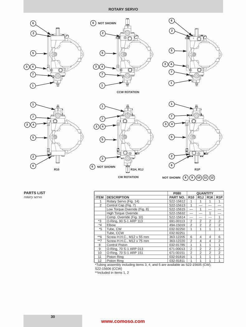
PARTS LISTrotary servo
P080 QUANTITYITEM DESCRIPTION PART NO. R10 R1J R1K R1P
1 Rotary Servo (Fig. 14) S22-15612 1 1 1 12 Control Cap (Fig. 7) S22-15613 1 — — —
Low Torque Override (Fig. 8) S22-15615 — 1 — —High Torque Override S22-15632 — — 1 —Comp. Override (Fig. 10) S22-15614 — — — 1
*3 O-Ring, 90 S-1 ARP 113 691-00113 2 2 2 2*4 Elbow 494-15019 2 2 2 2*5 Tube, CW 032-92250 1 1 1 1
Tube, CCW 032-92251**6 Screw-H.H.C., M12 x 55 mm 363-12205 6 4 4 6**7 Screw-H.H.C., M12 x 75 mm 363-12220 2 4 4 28 Control Piston 032-91785 1 1 1 19 O-Ring, 70 S-1 ARP 013 671-00013 2 2 2 210 O-Ring, 70 S-1 ARP 151 671-00151 2 2 2 211 Piston Ring 032-91816 1 1 1 112 Piston Ring 032-91811 1 1 1 1
*Tubing assembly including items 3, 4, and 5 are available as S22-15605 (CW),S22-15606 (CCW)**Included in items 1, 2
43
7
1
2
5
6
1
7
43
5
2
6
43
7
1
2
5
1
7
43
5
2
43
7
1
2
5
6
1
7
43
5
2
66 NOT SHOWN
6 NOT SHOWN
R10 R1H, R1J R1P
NOT SHOWN 8 9 10 11 12CW ROTATION
CCW ROTATION
www.comoso.com
1. See Figure 14. Remove 2 screws holding body (16) to cap assembly (1).
2. Remove all parts from body (16) except pin (30) and arm assembly (28). It is notnecessary to remove these parts unless broken or worn. Examine parts for wear ordamage.
3. Remove screw (3). Examine head for excessive wear, and body for smooth sealingsurface with O-ring.
4. See Figure 6. Remove tube lines to cap assembly.
5. Remove screws holding cap assembly to pump body.
6. Remove cap assembly (1). Remove plug (4) with attached parts. Remove spring(11) and spool (6).
7. Do not remove sleeve in body (1). Sleeve is pressed into cap and finished to size. Ifsleeve or cap is worn, replace the cap-sleeve assembly (1).
8. Remove screw (13) and nut (14). Remove the retainer (7).
1. See Figure 6. Install Avseal plug (9) in cap.
2. Install spool (6) into bore as shown. Install spring (11) over end of spool.
3. Install O-ring (8) on spring retainer (7). Install retainer (7), screw (13) and nut (14) inplug (4).
4. Install O-ring (15) in bottom of bore as shown. Install O-ring (10) on plug (4). Installplugs (4) and (12) in body (1). Torque plugs to 60 Nm. Install O-ring (18) in cap.
5. Turn screw (13) in until spring retainer (7) contacts spring (11). Turn an additional1-1/2 turns and lock in position.
6. Note proper location for control on pump. Install O-rings on interface between capand pump control pad. Install cap on pump control pad, guiding the control piston intothe bore.
7. Install and torque two assembly bolts to 102 Nm.
8. See Figure 14, Apply Loctite 242 on threads of screw (3), lubricate the shank,thread through the cap into the control piston, and torque to 6,78 Nm.
9. Install minimum stop screw (24) and turn clockwise to stroke pump to full stroke.Measure height from control cap to top of screw (3). With control piston at full stroke,dimension must be 19,2 +/- 0,76 mm. Back out minimum stop screw (24) till there is nocontact with control piston.
10. Press dowel (30) into body (16), through the link (28), to 1/4 in. (6.35 mm) belowsurface. Apply Loctite hydraulic sealant to threads of screws (39) and install over dowel(30).
11. Press spool (21) into retainer (19). Caution: do not use excessive force.
12. While sleeve (27) is engaged into dowel on link (28), slide above spool assemblywith spring (15) into bore of body (16), and through sleeve (27). Spool (21) must movefreely and easily at all positions of the link (28).
13. Press dowel (34) through slide pin (14), while inside shaft (10). Dowel (34) mustevenly extend from both sides of slide pin (14).
14. Assemble all other components into body (16) per figure 14. Torque plug (12) to 60Nm.
15. While spring retainer is engaging clevis pin (5) under dowel of link (28), slide theother opening of spring retainer over the top of the screw (3). Attach body assembly(16) to cap (1) with two screws and torque to 102 Nm.
1. Plumb 82,8 bar servo supply to control.
2. Thread zero screw (24) so that pump is on stroke.
3. Start pump.
4. With shaft (10) rotated fully clockwise, thread cam (9) until output flow is at the fullstroke position. Lock in place.
5. Fully rotate shaft (10) counter-clockwise. Pump flow should go towards zero stroke.Back out zero screw (24) until pump is at zero stroke. Lock in place.
6. If pump fails to go towards full stroke, or fails to go towards zero stroke, differentialpressure may be improperly adjusted. Re-adjust the screw (13 figure 6) out to gotowards full or in to go towards zero flow. When correct, lock in place and install cap ondifferential adjustment.
7. Rotate shaft clockwise and counterclockwise at approximately 34,5 bar, 207 barand 414 bar system pressure. Pump stroke should follow shaft rotation between full andzero stroke smoothly and proportionally. Full to zero or zero to full stroke should beachieved in no more than 0,7 second.
ROTARY SERVO
ROTARY SERVODISASSEMBLY
ASSEMBLY
TEST AND ADJUSTMENT
31www.comoso.com

32
ROTARY SERVO
ITEM DESCRIPTION PART NO. QTY.1 Cap (Figure 6) S22-15619 13 Screw 032-91461 15 Pin, Clevis 321-40000 16 Spring, Compression 032-92100 17 Plug, Avseal 447-00026 18 Locknut 8-LSN-S 492-15116 19 Cam 032-91515 110 Shaft 032-91514 111 O-Ring, 90 S-1 ARP 012 691-00012 112 Plug, 8HP5N-S 488-35018 114 Slide Pin 032-91513 115 Spring 225-92105 116 Body S22-15393 117 Retaining Ring 356-31050 118 O-Ring, 90 S-1 ARP 908 691-00908 219 Spring Retainer 032-91516 120 Nut 032-91822 121 Spool 032-91438 123 O-Ring, 70 S-1 ARP 115 671-00115 124 Soc. Setscrew, M16 -2 x 80mm 311-50001 125 Plug, 12 HP5N-S 488-35014 126 O-Ring, 90 S-1 ARP 912 691-00912 127 Sleeve 032-91437 128 Arm assembly S22-15520 129 O-Ring, 70 S-1 ARP 035 671-00035 130 Dowel Pin, 1/8 Dia x 1.50 Lg. 324-20824 133 O-Ring, 70 S-1 ARP 904 671-00904 134 Dowel Pin, 1/8 x 5/8 324-20810 135 O-Ring, 70 S-1 ARP 011 671-00011 236 Plate 032-91510 137 Screw, HHC,1/4-20 x 3/4 306-40142 338 Plug, SAE-4 488-35061 139 Screw, SHC 10-32 x 1/4 312-09041 245 O-ring, 70 S-1 ARP 010 671 00010 1
PARTS LIST FOR FIGURE 14Assembly No.. S22-15612
FIGURE 14ROTARY SERVO
Loctitehydraulicsealant
cylinder press.1/4 BSPPtorque 30 Nm
servo connection3/8 BSPP
max. stroke adjust.
torque102 Nm
Loctite 242torque 6,8 Nm
torque 68 Nm
www.comoso.com

33
LOAD SENSING CONTROL
LOAD SENSING CONTROLparts list
P080 QTY.ITEM DESCRIPTION PART NO. L10 L20
1 Max. Vol. Stop (Fig. 1) S22-15467 1 —Max Vol. Handwheel (Fig. 2) S22-15448 — 1
*2 Load Sensing Control (Fig. 15) *S22-15625 1 —Load Sensing Control *S22-15637 — 1
3 Buck Up Cap (Fig. 4) S22-15447 1 14 Screw-H.H.C., M12 x 55 mm 363-12205 6 45 Screw-H.H.C., M12 x 75 mm 363-12220 — 26 Screw-H.H.C., M12 x 85 mm 363-12233 2 27 Control Piston 032-91836 1 18 O-Ring, 70 S-1 ARP 013 671-00013 2 29 O-Ring, 70 S-1 ARP 151 671-00151 2 210 Piston Ring 032-91816 2 2
*Includes items 1, 4, 5, 6
CCW ROTATION
CW ROTATION
1
2
3
4
3
2
4
1
5
2
3
4
3
6
1
2
4
7 8 9 10ITEMS
NOT SHOWN
L20L101 6
6
56
www.comoso.com
1. See Figure 15 Back off max. volume screw to full displacement. Remove max. vol-ume screw assembly.
2. Remove bolts holding cap to pump.
3. Remove isolation valve (29) from block (28). Remove plug (15) and attached parts.Remove spring (11) and spool (18).
4. Remove adj. plug (2) and attached parts. Remove seal piston (5). Note: a 10-24 screwmay be used to assist in pulling the piston. Remove spring (7) and cone (8).
5. Do not remove sleeve in body (1). Sleeve is pressed into cap and finished to size. Ifsleeve or cap is worn, replace the cap-sleeve assembly (1).
6. Examine seat (10) for wear. Do not remove unless damaged.
1. Install Avseal plugs (9) and orifice (19) in body.
2. Press seat (10) into bore squarely against shoulder in bore.
3. Install spool (18) into bore as shown. Install spring (11) over end of spool. Install O-ring(6) on seal piston (16). Lubricate and install into plug (15). Install O-ring (14 in bore asshown. Install O-ring (13) on plug (15) and install plug into cap. Install screw (3) and nut (4).Cap (17) will be installed after test and final adjustment.
4. Install O-ring (6) on seal piston (5).
5. Lubricate O-ring and install cone (8), spring (7) and seal piston into bore in cap (1),being careful that cone enters seat (10). Install remaining parts in body (1). Torque plug (12)to 60 Nm. Torque plug (35) to 35 Nm.
6. Install O-rings (29-a) and (29-b) on valve (29). Observe that backup ring on insidegroove is toward the outside, the one on the middle groove is toward the inside, and the oneon the outside groove is toward the outside. Lubricate and install valve (29) in block (28),being careful to avoid damaging the O-rings. Torque to 68 Nm.
7. Install O-ring (32) on adapter (36). Install adapter in block (28). Install plug (31) inadapter.
8. Note proper location for cap on pump. Install O-rings on interface between cap andpump control pad. Install O-rings (26) in block (28).
9. Install block (28) on cover (1) with M24 x 85 mm lg mounting bolts. Install on pumpcontrol pad, guiding the control piston into the bore.
10. Install maximum volume stop. Torque mounting bolts to 102 Nm.
Connect pump to a circuit with system flow metered by a needle valve or suitable meteringvalve. Connect load sensing line downstream of the metering valve. Connect gage to pumpoutput, and to load sensing line, capable of measuring 20,7 bar pressure difference at 345bar.
Connect a relief valve downstream of the metering valve, and a flowmeter to measure pumpflow.
1. Adjust maximum volume stop to full displacement by backing off stop till there is no con-tact with the control piston.
2. Turn compensator adjustment screw (25) CCW until there is no contact with spring,then adjust 1/2 turn CW after contact is made with spring.
3. Turn differential adjustment screw (3) CCW until there is no contact with spring, thenadjust 1/2 turn CW after contact is made with spring.
4. Open metering valve and set relief valve at 35 bar.
5. Start prime mover. Pump should be at full displacement at 35 bar.
6. Increase system relief valve until compensator de-strokes pump to zero displace-ment. Set compensator to 103 bar.
7. Close the metering valve. Check the pressure difference from pump output to loadsensing line. Using the differential adjustment, set this pressure difference to 24 ± 1.7 bar orshop order requirement.
8. Set the compensator to 207 bar, and 345 bar. At each condition, increase the systempressure until the pump fully de-strokes. At no time should the system pressure vary morethan 10,3 bar from the compensator setting. The control should be steady and stable at allconditions.
9. Open the metering valve till pump reaches full flow at 69 bar. Reduce flow by 38 L/m.Raise the relief valve setting till the pump compensates at 345 bar. Reduce relief valve set-ting 14 bar. Flow to return to previous value ± 7.6 L/m.
10. Check pressure differential at 69, 138, and 207 bar ± 6,9 bar. Pressure differential toremain the same as in (7) above.
11. Set the flow to 38 l/m at 69 bar. Observe flow as pressure is varied from 34,5 bar to331 bar. Flow shall not vary by more than ±7,6 l/m).
12. Set load relief valve at 138 bar. Check pressure differential at 38 and 114 ± 7,6 l/m.Pressure differential shall be the same as in (7) above.
13. Set compensator adjustment to the required setting, or 345 bar if not otherwisenoted. Install cap on differential adjustment.
LOAD SENSING CONTROL
LOAD SENSING CONTROLDISASSEMBLY
ASSEMBLY
TEST AND ADJUSTMENT
34www.comoso.com
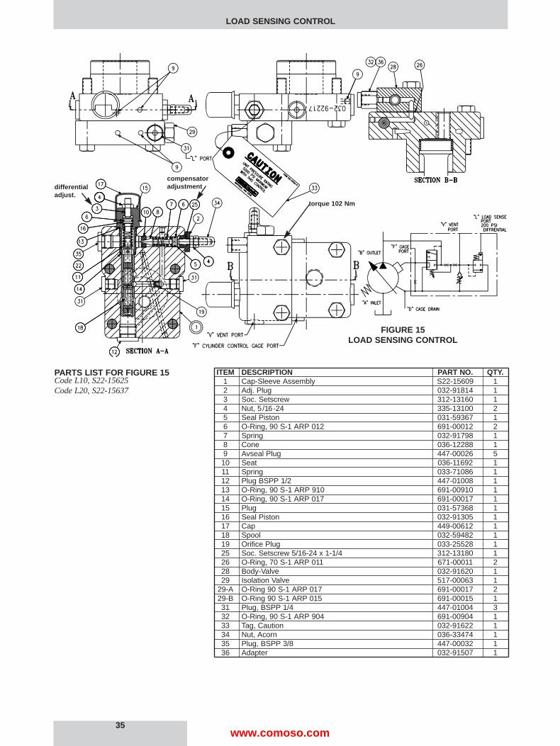
ITEM DESCRIPTION PART NO. QTY.1 Cap-Sleeve Assembly S22-15609 12 Adj. Plug 032-91814 13 Soc. Setscrew 312-13160 14 Nut, 5/16-24 335-13100 25 Seal Piston 031-59367 16 O-Ring, 90 S-1 ARP 012 691-00012 27 Spring 032-91798 18 Cone 036-12288 19 Avseal Plug 447-00026 510 Seat 036-11692 111 Spring 033-71086 112 Plug BSPP 1/2 447-01008 113 O-Ring, 90 S-1 ARP 910 691-00910 114 O-Ring, 90 S-1 ARP 017 691-00017 115 Plug 031-57368 116 Seal Piston 032-91305 117 Cap 449-00612 118 Spool 032-59482 119 Orifice Plug 033-25528 125 Soc. Setscrew 5/16-24 x 1-1/4 312-13180 126 O-Ring, 70 S-1 ARP 011 671-00011 228 Body-Valve 032-91620 129 Isolation Valve 517-00063 1
29-A O-Ring 90 S-1 ARP 017 691-00017 229-B O-Ring 90 S-1 ARP 015 691-00015 131 Plug, BSPP 1/4 447-01004 332 O-Ring, 90 S-1 ARP 904 691-00904 133 Tag, Caution 032-91622 134 Nut, Acorn 036-33474 135 Plug, BSPP 3/8 447-00032 136 Adapter 032-91507 1
LOAD SENSING CONTROL
PARTS LIST FOR FIGURE 15Code L10, S22-15625Code L20, S22-15637
35
FIGURE 15LOAD SENSING CONTROL
torque 102 Nm
differentialadjust.
compensatoradjustment
www.comoso.com
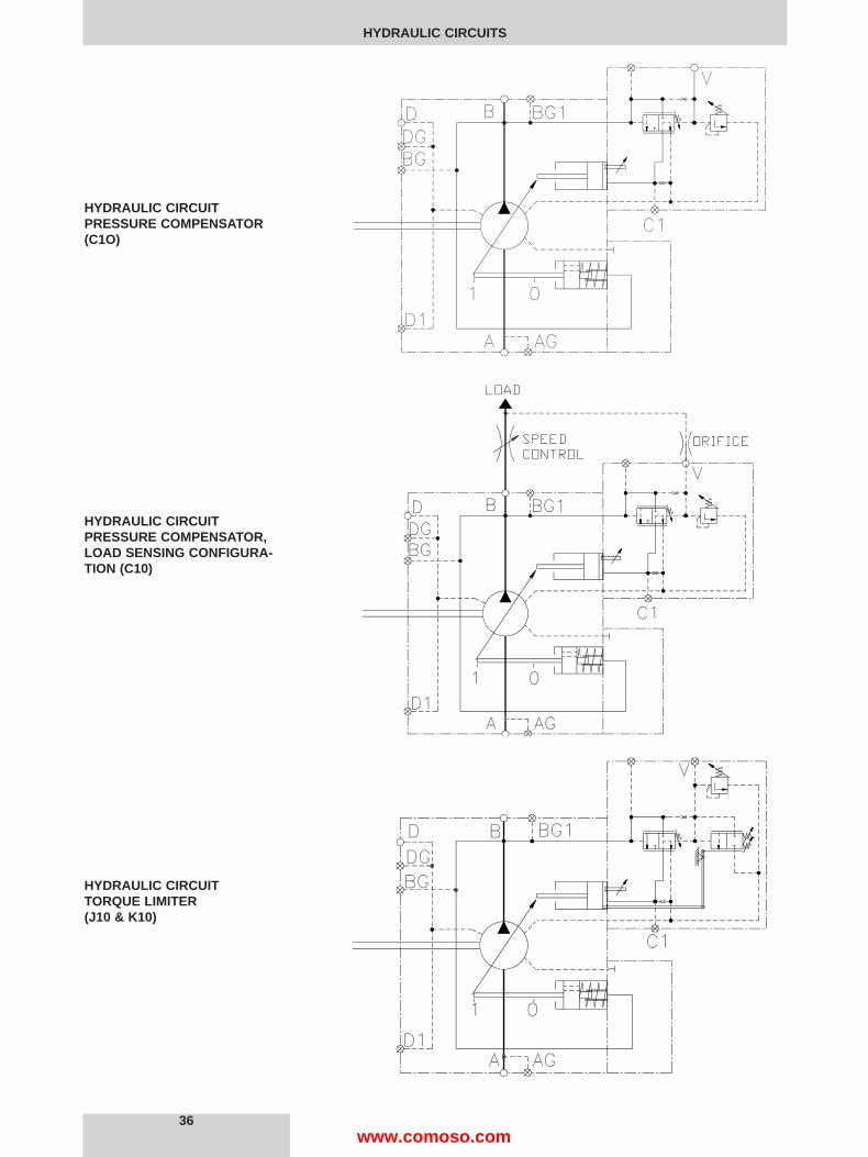
36
HYDRAULIC CIRCUITS
HYDRAULIC CIRCUITPRESSURE COMPENSATOR(C1O)
HYDRAULIC CIRCUITPRESSURE COMPENSATOR,LOAD SENSING CONFIGURA -TION (C10)
HYDRAULIC CIRCUITTORQUE LIMITER (J10 & K10)
www.comoso.com

37
HYDRAULIC CIRCUITS
HYDRAULIC CIRCUITROTARY SERVO(R10)
HYDRAULIC CIRCUITROTARY SERVO WITH COMPENSATOR OVERRIDE (R1P)
HYDRAULIC CIRCUITROTARY SERVO WITH TORQUELIMITER OVERRIDE(R1J & R1K)
www.comoso.com
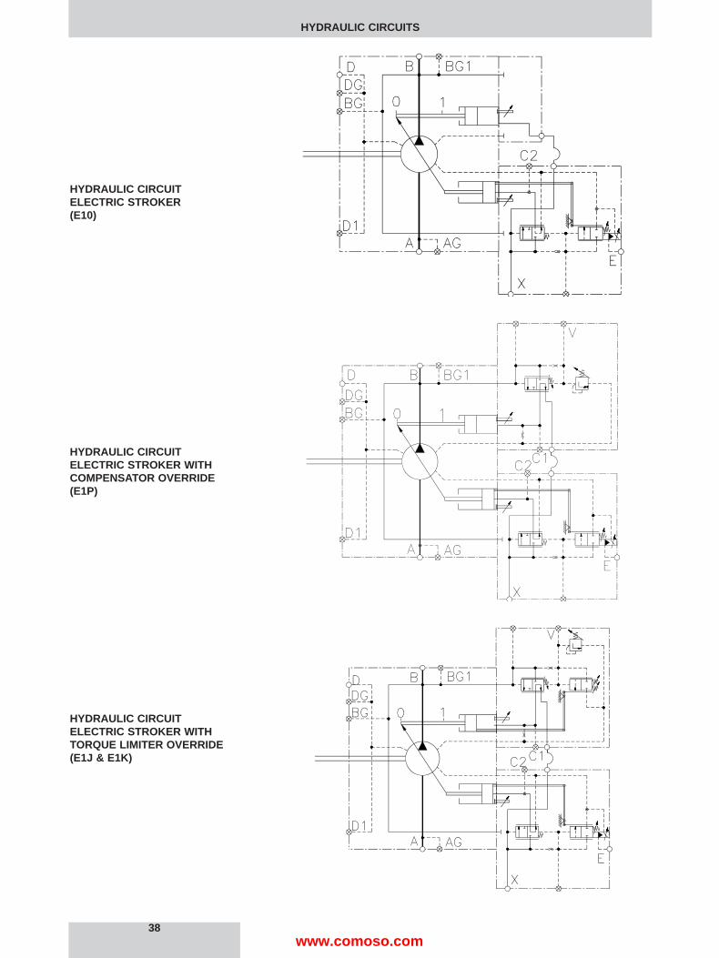
38
HYDRAULIC CIRCUITS
HYDRAULIC CIRCUITELECTRIC STROKER(E10)
HYDRAULIC CIRCUITELECTRIC STROKER WITHCOMPENSATOR OVERRIDE(E1P)
HYDRAULIC CIRCUITELECTRIC STROKER WITHTORQUE LIMITER OVERRIDE(E1J & E1K)
www.comoso.com
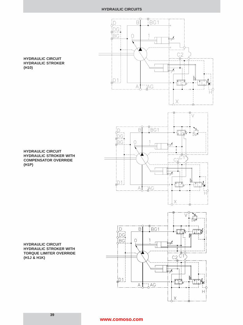
39
HYDRAULIC CIRCUITS
HYDRAULIC CIRCUITHYDRAULIC STROKER (H10)
HYDRAULIC CIRCUITHYDRAULIC STROKER WITHCOMPENSATOR OVERRIDE(H1P)
HYDRAULIC CIRCUITHYDRAULIC STROKER WITHTORQUE LIMITER OVERRIDE(H1J & H1K)
www.comoso.com

40
HYDRAULIC CIRCUITS, STROKER PERFORMANCE CUR VES
HYDRAULIC CIRCUITLOAD SENSING CONTROL(L10)
90
75
60
45
30
15
02 4 6 8 10 12 14 16
CONTROL PRESSURE, BAR
DIS
PLA
CE
ME
NT
,CC
/RE
V.
90
75
60
45
30
15
0
DIS
PLA
CE
ME
NT
,CC
/RE
V.
HYDRAULIC STROKER PERFORMANCE
ELECTRIC STROKERPERFORMANCE, 24 V. COIL
125 150 175 200 225 250 275 300 325 350CONTROL SIGNAL, mA
90
75
60
45
30
15
0
DIS
PLA
CE
ME
NT
,CC
/RE
V.
250 300 350 400 450 500 550 600 650 700CONTROL SIGNAL, mA
ELECTRIC STROKERPERFORMANCE, 12 V. COIL
www.comoso.com

1.7210-1.7160
FLAT ROOT SIDE FIT EXTERNAL CLASS-1SAE INVOLUTE SPLINE DATA J498-B 1969
OPTIONAL KEYED SHAFT(COUPLING DRIVE)
A
30 DEGREE PRESSURE ANGLE13 TEETH
8/16 PITCH
MAJOR DIA.(43,713-43,586)
A
CW ROTATION
.81DIA.(20,6)
4 PLACES
STANDARD ADJ. MAXIMUM VOL. STOP
6.29(159,9)
8.18(207,8)
9.00(228,6)SQUARE
4.50(114,3)
10.50(266,7)SQUARE
5.25(133,4)
(158,2)6.23
DEEP(30,2)1.19
1/2-13 UNC X4 PLACES
3000 PSI(209 BARS)
DIA.2.50(63,5)
INLET PORT
SAE-
4-BOLT FLG. CONN.
DIA.
"D" CASE DRAINSAE-12 STR. THD.
SAE-4 STR. THD.
DP1.19
(30,2)1/2-13 UNC X4 PLACES
30°
ALTERNATE HANDWHEEL ADJ.
(294,6)11.60
MAXIMUM VOLUME STOP
4.37(111,1)
2.56(65,0)
7.00(177,7)
1.25(31,8)
4.11(104,4)1.31
(33,3)
11.36(288,5)
SAE-4 STR. THD.
1.00(25.4)
2.00(50.8)
13.44(341,3)MAX.
REAR ADAPTERSSEE PAGES 42, 43 & 44
OPTIONAL
1.943(49,35)
SAE-12 STR. THD.
COMPENSATOR ADJUSTMENT
2.63(66,7)
4.11(104,4)
DIA.
SQUARE KEY x LG.
SAE-8 STRAIGHT THREADCOMPENSATOR VENT CONNECTION CASE DRAIN "D1"
CASE BLEED/GAGE CONNECTION
INLET GAGE CONNECTIONSAE-4 STRAIGHT THREAD
OUTLET GAGE CONNECTION
VIEW A-A
-A-
SAE-4 STRAIGHT THREADCONTROL CYL. GAGE PORT
-A-
7250 PSI(505 BARS)
DIA.
OUTLET PORT
1.25(31,8)SAE-
4-BOLT FLG. CONN.
.63(15,9)
13.58(344,9)
1.75(44.5)
3.50(88.9)
4.37(111,1)
1.09(27,7)
2.902.97
73,775,4
44,4044,451.7481.750
152,35152,405.9986.000
.4355
.4375
11,11211,062
1.75(44,4) (2,3)
.09
SPLINELENGTH
1.62(41,0)
.49(12,5)
73,775,42.902.97
NO REAR DRIVE
13.40(340,4)
CCW ROTATION
1. REFERENCE TO PUMP ROTATION, R-CW & L-CCW, IS AS
2. DIMENSIONS IN PARENTHESIS ARE METRIC (SI UNITS).VIEWED FROM SHAFT END.
NOTES:
• COMPENSATOR WITH ADJ. MAX. VOLUME SCREW STOP-C1* OR COMPENSATOR WITH HANDWHEEL ADJ. MAX. VOLUME STOP-C2*
(207,8)
COMPENSATORADJUSTMENT
8.18
6.23158,2
TAPPED HOLE3/8-16 UNC X .65
(16,5) DEEP
COMPENSATOR VENT CONNECTIONSAE-8 STRAIGHT THREAD
41
INSTALLATION DRAWINGS
www.comoso.com

SERVO PRESSURE INLETSEE CONTROL LOC.FOR PORT SPEC'S
( )
OUTLET PORT
OUTLET PORT
ELEC/HYD STROKERCONTROL PORTSAE-4(400-1000 PSI)
FULL ADJUSTMENT
CONTROL CYL. GAUGE PORTSAE-4 FAR SIDE
ZERO VOLUME ADJ.
ZERO VOLUME ADJ.
ZERO VOLUME ADJ.
FULL ADJUSTMENT
SERVO PRESSURE INLETSEE CONTROL LOC. FORPORT SPEC'S
CONTROL CYL. GAUGE PORTSAE-4 FAR SIDE
SERVO PRESSURE INLETSEE CONTROL LOC. FORPORT SPEC'S
HYD. STROKER PILOTCONTROL PRESSURE PORTSAE-4 (50-275 PSI)FAR SIDE
DIA. ROTARY INPUT SHAFT
CONTROL CYL. GAUGE PORTSAE-4 FAR SIDE
OUTLET PORT
PRIMARY SERVO CONTROLS(CCW ROTATION SHOWN)
• ELECTRO-HYDRAULIC STROKER - E1*
5.81(147,6)
2.69(68,3)
1.45(36,8)
2.69(68,3)
5.81(147,6)
5.13(130,2)
10.09(256,2)
7.36(187,1)
5.66(143,9)
.46(11,6)
.25(6,4)
5.13(130,2)
.500
.49812,7012,65
.44(11,2)FLAT
9.87(250,8)
5.66(143,9)
5.13(130,2)
10.09(256,2)
1.92(48,9)
5.66(143,9)
7.67(194,9)
( )
OUTLET PORT
ELEC/HYD STROKERCONTROL PORTSAE-4 (400-1000 PSI)
FULL ADJUSTMENT
ZERO VOLUME ADJ.
CONTROL CYL. GAUGE PORTSAE-4
DIA. ROTARY INPUT SHAFT
ZERO VOLUME ADJ.
SERVO PRESSURE INLETSEE CONTROL LOC. FORPORT SPEC'S
FULL ADJUSTMENT
ZERO VOLUME ADJ.
HYD. STROKER PILOTCONTROL PRESSURE PORTSAE-4 (50-275 PSI)
SERVO PRESSURE INLETSEE CONTROL LOC. FORPORT SPEC'S
CONTROL CYL. GAUGE PORTSAE-4
CONTROL CYL. GAUGE PORTSAE-4
OUTLET PORT
OUTLET PORT
1.88(47,8)
2.69(68,3)
5.81(147,6)
2.69(68,3)
5.81(147,6)
2.69(68,3)
3.93(99,7)
5.81(147,6)
5.13(130,2)
5.13(130,2)
.44(11,2) FLAT
.500
.49812,7012,65
7.67(194,9)
5.13(130,2)
1.92(48,9)
5.66(143,9)
10.09(256,2)
.25(6,4)
.46(11,6)
9.87(250,8)
5.66(143,9)
5.66(143,9)
7.36(187,1)
10.09(256,2)
SERVO PRESSURE INLET PORTSAE-6 (500-1000 PSI)
1.56(39,7)
2.07(52,6)
• CCW
SERVO PRESSURE INLET PORT
3.30(83,9)
SAE-6 (500-1000 PSI)
1.56(39,7)
• ROTARY SERVO - R1*
• HYDRAULIC STROKER - H1*
• HYDRAULIC STROKER - H1*
• ROTARY SERVO - R1*
• ELECTRO-HYDRAULIC STROKER - E1*
PRIMARY SERVO CONTROLS(CW ROTATION SHOWN)
2.69(68,3)
5.81(147,6)
1.88(47,8)
SERVO PRESSURE INLETSEE CONTROL LOC. FORPORT SPEC'S
• CW
SERVO PRESSURE INLET
42
INSTALLATION DRAWINGS
www.comoso.com
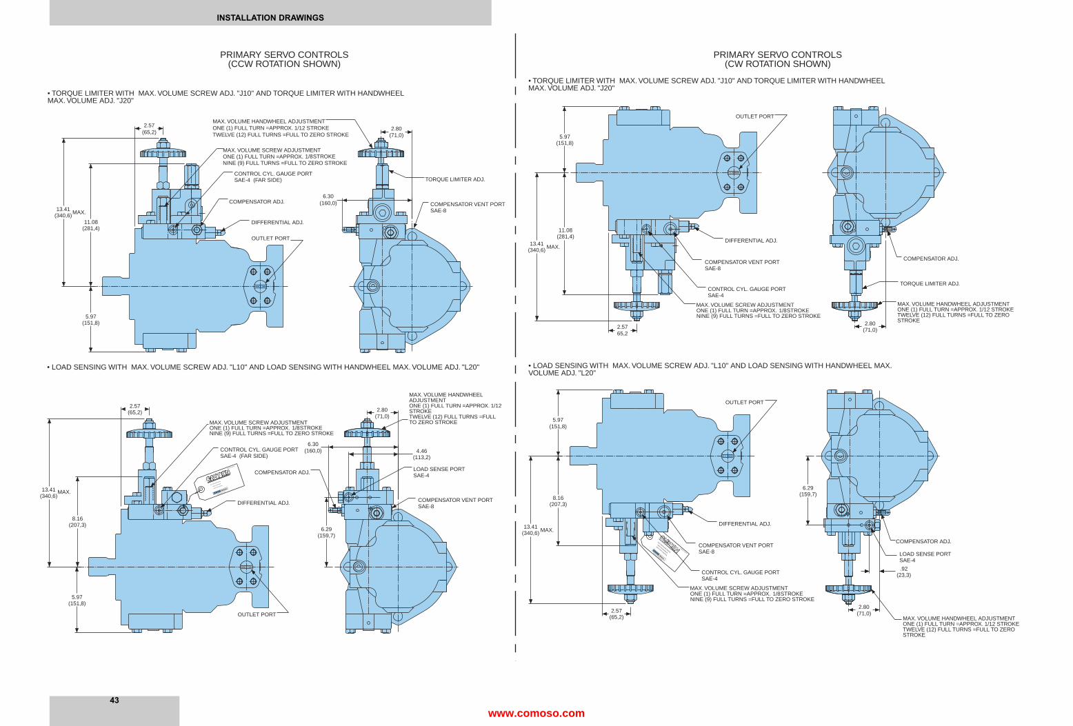
FORM 032-91622-A
MARYSVILLE, OHIO
UNIT PRESSURE RATING
5000 PSI MAXIMUM
WITH THIS CONTROL
CONTROL CYL. GAUGE PORTSAE-4 (FAR SIDE)
COMPENSATOR ADJ.
OUTLET PORT
OUTLET PORT
COMPENSATOR VENT PORTSAE-8
LOAD SENSE PORTSAE-4
MAX. VOLUME HANDWHEELADJUSTMENTONE (1) FULL TURN =APPROX. 1/12STROKETWELVE (12) FULL TURNS =FULLTO ZERO STROKEMAX. VOLUME SCREW ADJUSTMENT
ONE (1) FULL TURN =APPROX. 1/8 STROKENINE (9) FULL TURNS =FULL TO ZERO STROKE
DIFFERENTIAL ADJ.
DIFFERENTIAL ADJ.
COMPENSATOR ADJ.
CONTROL CYL. GAUGE PORTSAE-4 (FAR SIDE)
MAX. VOLUME SCREW ADJUSTMENTONE (1) FULL TURN =APPROX.NINE (9) FULL TURNS =FULL TO ZERO STROKE
MAX. VOLUME HANDWHEEL ADJUSTMENTONE (1) FULL TURN =APPROX. 1/12 STROKETWELVE (12) FULL TURNS =FULL TO ZERO STROKE
5.97(151,8)
11.08(281,4)
13.41(340,6)MAX.
2.57(65,2)
1/8 STROKE
TORQUE LIMITER ADJ.
COMPENSATOR VENT PORTSAE-8
6.30(160,0)
2.80(71,0)
2.80(71,0)
4.46(113,2)
6.30(160,0)
6.29(159,7)
2.57(65,2)
13.41(340,6)
MAX.
8.16(207,3)
5.97(151,8)
PRIMARY SERVO CONTROLS(CCW ROTATION SHOWN)
• TORQUE LIMITER WITH MAX. VOLUME SCREW ADJ. "J10" AND TORQUE LIMITER WITH HANDWHEELMAX. VOLUME ADJ. "J20"
• LOAD SENSING WITH MAX. VOLUME SCREW ADJ. "L10" AND LOAD SENSING WITH HANDWHEEL MAX. VOLUME ADJ. "L20"
NINE (9) FULL TURNS =FULL TO ZERO STROKE
DIFFERENTIAL ADJ.
COMPENSATOR VENT PORTSAE-8
ONE (1) FULL TURN =APPROX. 1/8 STROKEMAX. VOLUME SCREW ADJUSTMENT
CONTROL CYL. GAUGE PORTSAE-4
OUTLET PORT
13.41(340,6) MAX.
11.08(281,4)
5.97(151,8)
• TORQUE LIMITER WITH MAX. VOLUME SCREW ADJ. "J10" AND TORQUE LIMITER WITH HANDWHEELMAX. VOLUME ADJ. "J20"
2.5765,2
TORQUE LIMITER ADJ.
COMPENSATOR ADJ.
MAX. VOLUME HANDWHEEL ADJUSTMENTONE (1) FULL TURN =APPROX. 1/12 STROKETWELVE (12) FULL TURNS =FULL TO ZEROSTROKE2.80
(71,0)
MARYSVILLE, OHIO 43040
UNIT PRESSURE RATING
5000 PSI MAXIMUM
WITH THIS CONTROL
FORM 032-91622-A
COMPENSATOR VENT PORTSAE-8
ONE (1) FULL TURN =APPROX. 1/8 STROKEMAX. VOLUME SCREW ADJUSTMENT
NINE (9) FULL TURNS =FULL TO ZERO STROKE
COMPENSATOR ADJ.
DIFFERENTIAL ADJ.
CONTROL CYL. GAUGE PORTSAE-4
LOAD SENSE PORTSAE-4
OUTLET PORT
2.80(71,0)
.92(23,3)
6.29(159,7)
• LOAD SENSING WITH MAX. VOLUME SCREW ADJ. "L10" AND LOAD SENSING WITH HANDWHEEL MAX.VOLUME ADJ. "L20"
2.57(65,2)
13.41(340,6) MAX.
8.16(207,3)
5.97(151,8)
MAX. VOLUME HANDWHEEL ADJUSTMENTONE (1) FULL TURN =APPROX. 1/12 STROKETWELVE (12) FULL TURNS =FULL TO ZEROSTROKE
PRIMARY SERVO CONTROLS(CW ROTATION SHOWN)
43
INSTALLATION DRAWINGS
www.comoso.com

8.16(207.3)
"F" CYLINDER CONTROLGAUGE PORTSAE-4
6.30
2.69(68.3)
5.60(142,3)
COMPENSATOR ADJ.
2.69(68,2)
2.69(68.3)
OUTLET PORT
TORQUE LIMITERADJ.
OUTLET PORT
(160,0)
5.06(128.5)
2.97(75.5)
"V" COMPENSATOR VENT PORT(FAR SIDE) SAE-8
"F" CYLINDER CONTROLGAUGE PORTSAE-4
MAX. VOLUME ADJUSTMENTONE (1) FULL TURN =APPROX. 1/8 STROKE =NINE (9) FULL TURN =FULL TO ZERO STROKE
11.08(281.4)
8.16(207.3)
COMPENSATOR ADJ.
SECONDARY SERVO CONTROLSFOR "E", "H", & "R" PRIMARY CONTROLS
(CCW ROTATION SHOWN)
• TORQUE LIMITER OVERRIDE CONTROL "**J" FOR "E1", "H1", & "R1" CONTROLS
• COMPENSATOR OVERRIDE CONTROL "**P" FOR "E1", "H1", & "R1" CONTROLS
• BUCKDOWN CONTROL CAP "**O" FOR "E1", "H1", & "R1" CONTROLS
2.97(75.5)
MAX. VOLUME ADJUSTMENTONE (1) FULL TURN =APPROX. 1/8 STROKE =NINE (9) FULL TURN =FULL TO ZERO STROKE
6.30(160.0)
OUTLET PORT
"V" COMPENSATOR VENT PORT(FAR SIDE) SAE-8
MAX. VOLUME ADJUSTMENTONE (1) FULL TURN =APPROX. 1/8 STROKE =NINE (9) FULL TURN =FULL TO ZERO STROKE
• CONTROL LOCATION FOR CW ROTATION
PRIMARY CONTROLS
OUTLET PORT
SECONDARY CONTROLS
OUTLET PORT
PRIMARY CONTROLS
SECONDARY CONTROLS
• CONTROL LOCATION FOR CCW ROTATION
"F" CYLINDER CONTROLGAUGE PORT (FAR SIDE)SAE-4
MAX. VOLUME ADJUSTMENT
"V" COMPENSATOR VENT PORT
"V" COMPENSATOR VENT PORT
MAX. VOLUME ADJUSTMENT
MAX. VOLUME ADJUSTMENTONE (1) FULL TURN =APPROX. 1/8 STROKE
SAE-8
ONE (1) FULL TURN =APPROX.
ONE (1) FULL TURN =APPROX.
NINE (9) FULL TURNS =FULL TO ZERO STROKE
NINE (9) FULL TURNS =FULL TO ZERO STROKE
NINE (9) FULL TURNS =FULL TO ZERO STROKE
COMPENSATOR ADJ.
2.97(75.5)
OUTLET PORT
SAE-8
OUTLET PORT
COMPENSATOR ADJ.
TORQUE LIMITER ADJ.
• TORQUE LIMITER OVERRIDE CONTROL "**J" FOR "E1", "H1", & "R1" CONTROLS
SECONDARY SERVO CONTROLSFOR "E", "H", & "R" PRIMARY CONTROLS
(CW ROTATION SHOWN)
• BUCKDOWN CONTROL CAP "**O" FOR "E1", "H1", & "R1" CONTROLS
• COMPENSATOR OVERRIDE CONTROL "**P" FOR "E1", "H1", & "R1" CONTROLS
8.16(207.3)
11.08(281.4)
5.06(128.5)
1/8 STROKE
8.16(207.3)
2.97(75.5)
1/8 STROKE
5.81(147,6)
2.69(68.3)
2.69(68.3)
5.81(147,6)
5.81(147,6)
2.69(68.3)
OUTLET PORT
"F" CYLINDER CONTROLGAUGE PORT (FAR SIDE)SAE-4
44 www.comoso.com

41
CONTROLS KEY SHEET
P080 - * * * * - C 1 0 - *
Secondary control options Pre-tested control assembly
O-None S22-15613J-Low Torque Limiter Override (90 - 170 Nm) S22-15615K-High Torque Limiter Override (over 170 Nm) S22-15632P-Compensator Override S22-15614
Primary control options control assembly
1-Maximum volume screw S22-154672-Handwheel (available on Compensator, S22-15448Torque limiter and Load sensing controls)
Primary controls Pre-tested control assembly
C-Pressure Compensator C1*, S22-15623 C2*, S22-15633E-Electric Stroker E1*, S22-15610H-Hydraulic Stroker H1*, S22-15611J-Low Torque Limiter (90 - 170 Nm) J1*, S22-15624 J2*, S22-15634K-High Torque Limiter (over 170 Nm) K1*, S22-15631 K2*, S22-15636L-Load Sensing L1*, S22-15625 L2*, S22-15637R-Rotary Servo R1*, S22-15612
Available control combinations
C10, C20E10, E1J, E1K, E1PH10, H1J, H1K, H1PJ10, J20K10, K20L10, L20R10, R1J, R1K, R1P
www.comoso.com

CONVERSIONS & FORMULAS
DEFINITION & UNITdisplacement
flow
power
torque
pressure
weight
force
volume
area
length
temperature
viscosity
FLUID POWER FORMULASPump input torque lbs. in.
Pump input power hp
Pump output flow U.S. gpm
Fluid motor speed rpm
Fluid motor torque lbs. in.
Fluid motor power hp
(metric)Pump input torque Nm
Pump input power kW
Pump output flow Lpm
Fluid motor speed rpm(min-1) (tr/mn)
Fluid motor torque Nm
Fluid motor power kW
in3/rev x 16,387 = cm3/rev cm3/rev x 0,06102 = in3/rev
gpm x 3,78 = l/min l/min x 0,2642 = gpm
hp x 0,7457 = kW kW x 1,341 = hp
lb-ft x 1,3567 = Nm Nm x 0,7376 = lb-ft
lbs/in2 (psi) x 0,06895 = bar bar x 14,50 = lbs/in2 (psi)lbs/in2 (psi) x 6,895 = kPa kPa x 0,1450 = lbs/in2 (psi)
lb x 0,4536 = kg kg x 2,205 = lbs
lb x 4,448 = N N x 0,2248 = lbs
in3 x 16,387 = cm3 cm3 x 0,06102 = in3
in2 x 6,452 = cm2 cm2 x 0,1550 = in2
in x 25,4= mm mm x 0,03937 = in
degree F-32 = °C 1,8 x °C+32 = ° F1,8
cSt x 1,0 = mm2/sec mm2/sec x 1,0 = cSt
(SSU-14) ≈cSt cSt x 4,25 + 14≈SSU4,25
pressure(psi) x displacement (in3/rev)2π x mech. eff.
rpm x (in3/rev) x (psi)395934 x overall eff.
rpm x (in3/rev) x volumetric eff.231
231 x flow rate(U.S. gpm) x volumetric eff.displacement (in3/rev)
pressure(psi) x displacement (in3/rev) x mech. eff.2π
rpm x (in3/rev) x (psi) x overall eff.395934
pressure(bar) x displacement (cm3/rev20π x mech. eff.
rpm x (cm3/rev) x (bar)600000 x overall eff.
rpm x (cm3/rev) x volumetric eff.1000
1000 x flow rate (Lpm) x volumetric eff.displacement (cm3/rev)
pressure(bar) x displacement (cm3/rev) x mech. eff.20π
rpm x (cm3/rev) x (bar) x overall eff.600000
“The product information specifications and descriptions contained in this catalog have been compiled for the use and convenience of our customers from information furnished by the manufacturer, and we cannot and do not accept any responsiblility for the accuracy or correctnessof any description, calculation, specification or information contained herein. No such description,calculated, specified or information regarding the products being sold has been made part of thebasis of the bargain nor has same created or amounted to an express warranty that the productswould conform thereto. We are selling the goods and merchandise illustrated and describedin this catalog on an as is basis and disclaim any implied warranty , including any warrantyof merchantability or warranty of fitness for any particular purposes whatsoever , withrespect to the goods and merchandise sold. All manufacturer warranties shall be passed on toour customers, but we shall not be responsible for special, indirect, incidental or consequentialdamages resulting from the use of any of the products or information contained or described in thecatalog.”
42www.comoso.com

SALES & SER VICE WORLDWIDE
International DistributorsIn Eur ope:CyprusEastern EuropeThe Faroe IslandsFinlandGreeceIcelandNorwayPortugalSwitzerlandTurkey
In Africa:AlgeriaEgyptIvory CoastMoroccoNigeriaSouth AfricaTogoTunisia
In Middle East:IranIsraelLebanonPakistanQatarSaudi ArabiaSyriaUnited Arab Emirates
In Far East:IndonesiaKoreaMalaysiaNew ZealandPhilippinesThailand
AustraliaDENISON HYDRAULICS Pty. Ltd.41-43 St. Hillers RoadP.O. Box 192Auburn, N.S.W. 2144AustraliaTel. (612) 9646 5200Fax (612) 9643 1305
Other sales offices:QueenslandSouth Wantirna VictoriaWestern Australia
AustriaDENISON HYDRAULIK GmbHZweigniederlassung LinzHaidbachstraße 69A-4061 PaschingAustriaTel. (43) 7229 4887Fax (43) 7229 63092
BeneluxDENISON HYDRAULICSBENELUX B. V.Pascalstraat 1003316 DordrechtHollandTel. (31) 786179 900Fax (31) 786175 755
CanadaDENISON HYDRAULICSCANADA Inc.2320 Bristol Circle, Unit 1Oakville, ON L6H 5S2CanadaTel. (905) 829 5800Fax (905) 829 5805
Other sales offices:Montreal, QCCalgary, AB
DenmarkDENISON HYDRAULIKDENMARK A/SIndustrikrogen 2DK-2635 IshöjDenmarkTel. (45) 4371 15 00Fax (45) 4371 15 16
FinlandDENISON HYDRAULICSP.O. Box 36FIN-08101 LohjaFinlandTel (358) 208 33 045Fax (358) 207 33 045
FranceDENISON HYDRAULICSFRANCE SA14, route du Bois BlancBP 53918105 VierzonFranceTel. (33) 2 48 53 01 20Fax (33) 2 48 75 02 91
Other sales offices:BordeauxLyonParis
GermanyDENISON HYDRAULIK GmbHHerderstrasse 26D-40721 HildenGermanyTel. (49) 2103 940-6Fax (49) 2103 940-880
Other sales offices:DresdenHanoverStuttgart
Great BritainDENISON HYDRAULICS U.K.Ltd.Kenmore RoadWakefield 41, Industrial EstateWakefield, WF20XEWest YorkshireEnglandTel. (44) 19 24 826 021Fax (44) 19 24 826 146
Other sales offices:Burgess Hill
Hong Kong DENISON HYDRAULICS Ltd.Unit 2, 25/F Wharf Cable Tower9 Hoi Shing RoadTsuen WanN.T., Hong KongTel. (852) 24988381Fax (852) 24991522
ItalyDENISON HYDRAULICS S.r.l.Viale Europa 6820090 Cusago MilanoItalyTel. (39) 2 90330 1Fax (39) 2 90390 695
JapanDENISON JAPAN Inc.4-2-1 Tsujido-ShinmachiFujisawa 251, JapanTel. (81) 466 35 3257Fax (81) 466 35 2029
Other sales office:Osaka
Mexico, Central America, South America and CaribbeanCountries ContactDENISON HYDRAULICS Inc.6167 NW 181 Terrace Circle NorthMiami, FL 33015USATel. (305) 362 2246Fax (305) 362 6220
P.R. ChinaDENISON HYDRAULICS Ltd.3F, No. 1, Mao Jia Zhai, Bai Lian JingPudong New Area,Shanghai 200126, ChinaTel. (86) 21 5886 8991Fax (86) 21 5886 1978
SingaporeDENISON HYDRAULICS S.E.A. Pte.Ltd.No. 11 Lorong Tukang DuaSingapore 2261Tel. (65) 2687840Fax (65) 2687847
SpainDENISON HYDRAULICS, S.A.Gomis, 108023 BarcelonaSpainTel. (34) 3418 46 87Fax (34) 3211 65 07
Other sales offices:San Sebastian
SwedenDENISON HYDRAULICSSVENSKA ABSporregatan 13213 77 - MalmöSwedenTel. (46) 40 21 04 40Fax (46) 40 21 47 26
Other sales offices:Spånga
TaiwanDENISON HYDRAULICS Ltd.6F-10, No. 79, Sec. 2, Roosevelt road,Taipei, Taiwan, R.O.C.Tel. (886) 2 3645101 / 3645102Fax (886) 2 3639025
USADENISON HYDRAULICS Inc.14249 Industrial ParkwayMarysville, OH 43040USATel. 937 644 3915Fax 937 642 3738For nearest Distributor:Call toll free 1 800 551 5956
Other sales offices:Fulton, CAMulberry, FLMoline, ILRock Island, ILKentwood, MIMedina, OHPortland, ORMemphis, TNArlington, TXHouston, TX
Other European, Middle Eastand African Countries ContactDENISON HYDRAULICSFRANCE SA14, route du Bois BlancBP 539 18105 Vierzon CedexFranceTel. (33) 2 48 53 01 44Fax (33) 2 48 53 01 46
06-97
Your local DENISON representative
Internet: http://www .denisonhydraulics.com E-mail: denison@ denisonhydraulics.com
www.comoso.com
Related Documents