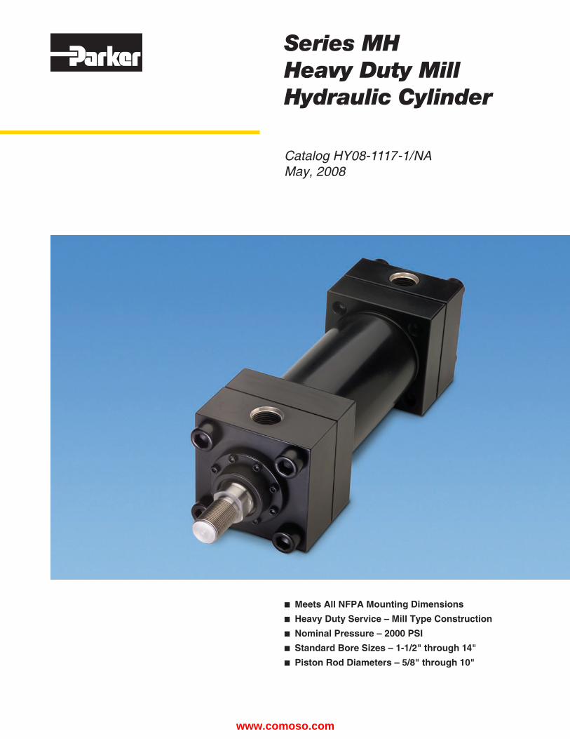
Series MH Heavy Duty Mill Hydraulic Cylinder n Meets All NFPA Mounting Dimensions n Heavy Duty Service – Mill Type Construction n Nominal Pressure – 2000 PSI n Standard Bore Sizes – 1-1/2" through 14" n Piston Rod Diameters – 5/8" through 10" Catalog HY08-1117-1/NA May, 2008 www.comoso.com

Welcome message from author
This document is posted to help you gain knowledge. Please leave a comment to let me know what you think about it! Share it to your friends and learn new things together.
Transcript
Series MH Heavy Duty Mill Hydraulic Cylinder
n Meets All NFPA Mounting Dimensionsn Heavy Duty Service – Mill Type Constructionn Nominal Pressure – 2000 PSIn Standard Bore Sizes – 1-1/2" through 14"n Piston Rod Diameters – 5/8" through 10"
Catalog HY08-1117-1/NAMay, 2008
www.comoso.com

The heavy-duty mill hydraulic cylinder with features only Parker can promise– and deliver!Series MH cylinders keep on performing like you expect from Parker — millions of trouble-free cycles. Everything you need for reliable 2,000 psi performance: n Chrome-plated, induction hardened piston rods.
n Heads retained with ASTM A-574 socket head cap screws.
n Floating cushions with float-check action and positive metal-to-metal seal.
n And every cylinder is individually tested before it leaves our plant.
Certified DimensionsParker Cylinders guarantees that all cylinders ordered from this catalog will be built to dimensions shown. All dimensions are certified to be correct, and thus it is not necessary to request certified drawings.
Catalog HY08-1117-1/NAFeatures/Benefits
Parker Hannifin CorporationDes Plaines, IL USAMilton, Ontario Canada
Heavy Duty Mill Hydraulic CylinderSeries MH
Offer of SaleThe items described in this document are hereby offered for sale by Parker Hannifin Corporation, its subsidiaries or its authorized distributors. This offer and its acceptance are governed by provisions stated on a separate page of the document entitled ‘Offer of Sale’.
WarningFAILURE OR IMPROPER SELECTION OR IMPROPER USE OF THE PRODUCTS AND/OR SYSTEMS DESCRIBED HEREIN OR RELATED ITEMS CAN CAUSE DEATH, PERSONAL INJURY AND PROPERTY DAMAGE.
This document and other information from Parker Hannifin Corporation, its subsidiaries and authorized distributors provide product and/or system options for further investigation by users having technical expertise. It is important that you analyze all aspects of your application, including consequences of any failure and review the information concerning the product or system in the current product catalog. Due to the variety of operating conditions and applications for these products or systems, the user, through its own analysis and testing, is solely responsible for making the final selection of the products and systems and assuring that all performance, safety and warning requirements of the application are met.
The product described herein, including without limitation, product features, specifications, designs, availability and pricing, are subject to change by Parker Hannifin Corporation and its subsidiaries at any time without notice.
www.comoso.com
Parker Hannifin CorporationDes Plaines, IL USAMilton, Ontario Canada
Heavy Duty Mill Hydraulic CylinderSeries MH
1
Design Features and Materials...............................................................................................................................2-3
Cushion Data ..........................................................................................................................................................2-3
How to Order .............................................................................................................................................................4
Mounting Style Index .................................................................................................................................................5
Dimensions: 1 1/2" - 8" Bore .............................................................................................................................6-13
10" - 14" Bore .............................................................................................................................16-23
Double Rod Models ............................................................................................................................................14-15
Accessories ........................................................................................................................................................24-25
Style 55 Rod End, Split Coupler, and Weld Plate...............................................................................................26-27
Linear Alignment Coupler ........................................................................................................................................27
Spherical Bearing Mounting Accessories ................................................................................................................28
Metallic Rod Wiper ..................................................................................................................................................29
Gland Drain .............................................................................................................................................................29
Air Bleeds ................................................................................................................................................................29
Piston Rod Boots .....................................................................................................................................................29
Proximity Switches .............................................................................................................................................30-35
Low Friction Seals ..............................................................................................................................................36-37
Ports ........................................................................................................................................................................38
Hydraulic Cylinder Speeds ......................................................................................................................................39
Acceleration and Deceleration Force Determination ...............................................................................................40
Stop Tube ................................................................................................................................................................41
Thrust-Key Retainer Plate .......................................................................................................................................41
Piston Rod Selection ..........................................................................................................................................42-43
Selecting Proper Cylinder Size and Pressure Table ...............................................................................................44
Assembly Torque Values .........................................................................................................................................45
Cylinder Safety Guide.........................................................................................................................................46-47
Parts Identification ...................................................................................................................................................48
Repair Kit .................................................................................................................................................................48
Offer of Sale ...................................................................................................................................Inside Back Cover
Table of Contents
Catalog HY08-1117-1/NATable of Contents
www.comoso.com
Parker Hannifin CorporationDes Plaines, IL USAMilton, Ontario Canada
2
Heavy Duty Mill Hydraulic CylinderSeries MH
Catalog HY08-1117-1/NAFeatures
The inside story on why Series MH is your best choice inheavy duty mill hydraulic cylinders
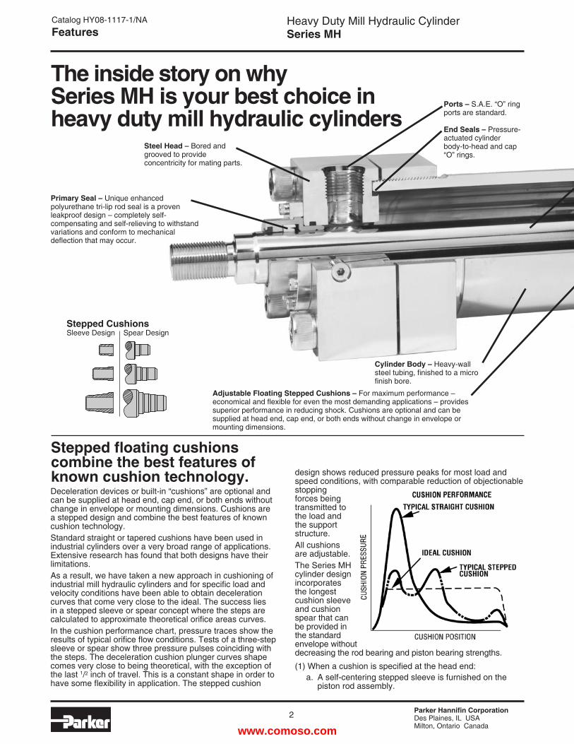
Stepped floating cushions combine the best features of known cushion technology.Deceleration devices or built-in “cushions” are optional and can be supplied at head end, cap end, or both ends without change in envelope or mounting dimensions. Cushions are a stepped design and combine the best features of known cushion technology.Standard straight or tapered cushions have been used in industrial cylinders over a very broad range of applications. Extensive research has found that both designs have their limitations.As a result, we have taken a new approach in cushioning of industrial mill hydraulic cylinders and for specific load and velocity conditions have been able to obtain deceleration curves that come very close to the ideal. The success lies in a stepped sleeve or spear concept where the steps are calculated to approximate theoretical orifice areas curves.In the cushion performance chart, pressure traces show the results of typical orifice flow conditions. Tests of a three-step sleeve or spear show three pressure pulses coinciding with the steps. The deceleration cushion plunger curves shape comes very close to being theoretical, with the exception of the last 1/2 inch of travel. This is a constant shape in order to have some flexibility in application. The stepped cushion
Adjustable Floating Stepped Cushions – For maximum performance – economical and flexible for even the most demanding applications – provides superior performance in reducing shock. Cushions are optional and can be supplied at head end, cap end, or both ends without change in envelope or mounting dimensions.
Cylinder Body – Heavy-wall steel tubing, finished to a micro finish bore.
Ports – S.A.E. “O” ring ports are standard.
End Seals – Pressure- actuated cylinder body-to-head and cap “O” rings.
Primary Seal – Unique enhanced polyurethane tri-lip rod seal is a proven leakproof design – completely self-compensating and self-relieving to withstand variations and conform to mechanical deflection that may occur.
design shows reduced pressure peaks for most load and speed conditions, with comparable reduction of objectionable stopping forces being transmitted to the load and the support structure. All cushions are adjustable. The Series MH cylinder design incorporates the longest cushion sleeve and cushion spear that can be provided in the standard envelope without decreasing the rod bearing and piston bearing strengths.
(1) When a cushion is specified at the head end: a. A self-centering stepped sleeve is furnished on the piston rod assembly.
Steel Head – Bored and grooved to provide concentricity for mating parts.
Stepped CushionsSleeve Design Spear Design
www.comoso.com
Parker Hannifin CorporationDes Plaines, IL USAMilton, Ontario Canada
Heavy Duty Mill Hydraulic CylinderSeries MH
3
Catalog HY08-1117-1/NAFeatures
Cap13/16
13/16
11/8
11/8
11/8
11/8
15/16
15/16
11/4
11/4
11/8
11/8
Cap11/2
11/2
115/16
115/16
2
2
Head*15/16
15/16
113/16
111/16
21/16
115/16
Head*11/8
11/8
11/8
11/8
11/8
11/8
13/8
11/16
13/8
11/16
11/16
11/16
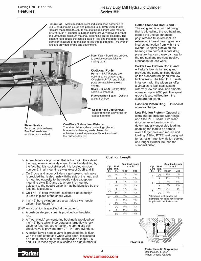
Piston Rod – Medium carbon steel, induction case-hardened to 54 Rc, hard chrome-plated and polished to 10 RMS finish. Piston rods are made from 90,000 to 100,000 psi minimum yield material in 5/8" through 4" diameters. Larger diameters vary between 57,000 and 90,000 psi minimum material, depending on rod diameter. The piston thread equals the catalog style #1 rod end thread for each rod diameter to assure proper piston-to-rod thread strength. Two wrench flats are provided for rod end attachment.
Steel Cap – Bored and grooved to provide concentricity for mating parts.
One-Piece Nodular Iron Piston – The wide piston surface contacting cylinder bore reduces bearing loads. Anaerobic adhesive is used to permanently lock and seal the piston to the rod.
Socket Head Cap ScrewsMade from high alloy steel for added strength.
Cushion Length – InchCyl.
BoreIn.
11/2
2
21/2
31/4
4
5
RodDia.In.5/8
1
1
13/8
1
13/4
13/8
213/4
21/2
231/2
Cushion Length – InchCyl.
BoreIn.
6
7
8
Cushion Length b. A needle valve is provided that is flush with the side of the head even when wide open. It may be identified by the fact that it is socket-keyed. It is located on side number 2, in all mounting styles except D, JB and E. c. On 5” bore and larger cylinders a springless check valve is provided that is also flush with the side of the head and is mounted opposite to the needle valve except on mounting style E, D and JJ, where it is mounted adjacent to the needle valve. It may be identified by the fact that it is slotted. d. On 11/2" - 4" bore cylinders, a slotted sleeve design is used in place of the check valve.
e. 11/2" - 2" bore cylinders use a cartridge style needle valve. (See Figure A)
(2) When a cushion is specified at the cap end: a. A cushion stepped spear is provided on the piston rod. b. A “float check” self-centering bushing is provided on 11/2" - 6" bore which incorporates a large flow check valve for fast “out-stroke” action. A springless ball check valve is provided from 7" - 14" bore cylinders. c. A socket-keyed needle valve is provided that is flush with the side of the cap when wide open. It is located on side number 2 in all mounting styles except E, D and HH. In these styles it is located on side number 3.
*Head end cushions for rod diameters not listed have cushion lengths with the limits shown.
RodDia.In.21/2
4
3
5
31/2
51/2
Optional PortsPorts – N.P.T.F. ports are optional at no extra charge. Oversize N.P.T.F. and S.A.E. ports are available at extra charge.Seals – Buna-N (Nitrile) static seals are standard.Fluorocarbon Seals – Optional at extra charge.
Bolted Standard Rod Gland – The rod gland is a unitized design that is piloted into the rod head and carries the unique enhanced polyurethane tri-lip rod seal. An extra-long inboard bearing surface insures lubrication from within the cylinder. A spiral groove on the bearing area helps eliminate drag pressure that can cause damage to the rod seal and provides positive lubrication for less wear.
Parker Low Friction Rod Gland – Parker’s low friction rod gland provides the same unitized design as the standard rod gland with low friction seals. The filled PTFE seals in tandem with the wiperseal offer a virtual zero leak seal system with very low slip-stick and smooth operation up to 2000 psi. The spiral groove is also utilized from the standard rod gland.
Cast Iron Piston Ring – Optional at no extra charge.
Low Friction Piston – Optional at extra charge. Includes wear rings and filled PTFE seals. Two wear rings serve as bearings which deform radially under side-loading, enabling the load to be spread over a larger area and reduce unit loading. A filled PTFE seal designed for extrusion-free, low friction service and longer cylinder life than the standard piston.
Piston Seals – Enhanced polyurethane PolyPak® seals are furnished as standard.
FIGURE A
www.comoso.com
Parker Hannifin CorporationDes Plaines, IL USAMilton, Ontario Canada
4
Heavy Duty Mill Hydraulic CylinderSeries MH
Catalog HY08-1117-1/NAHow To Order
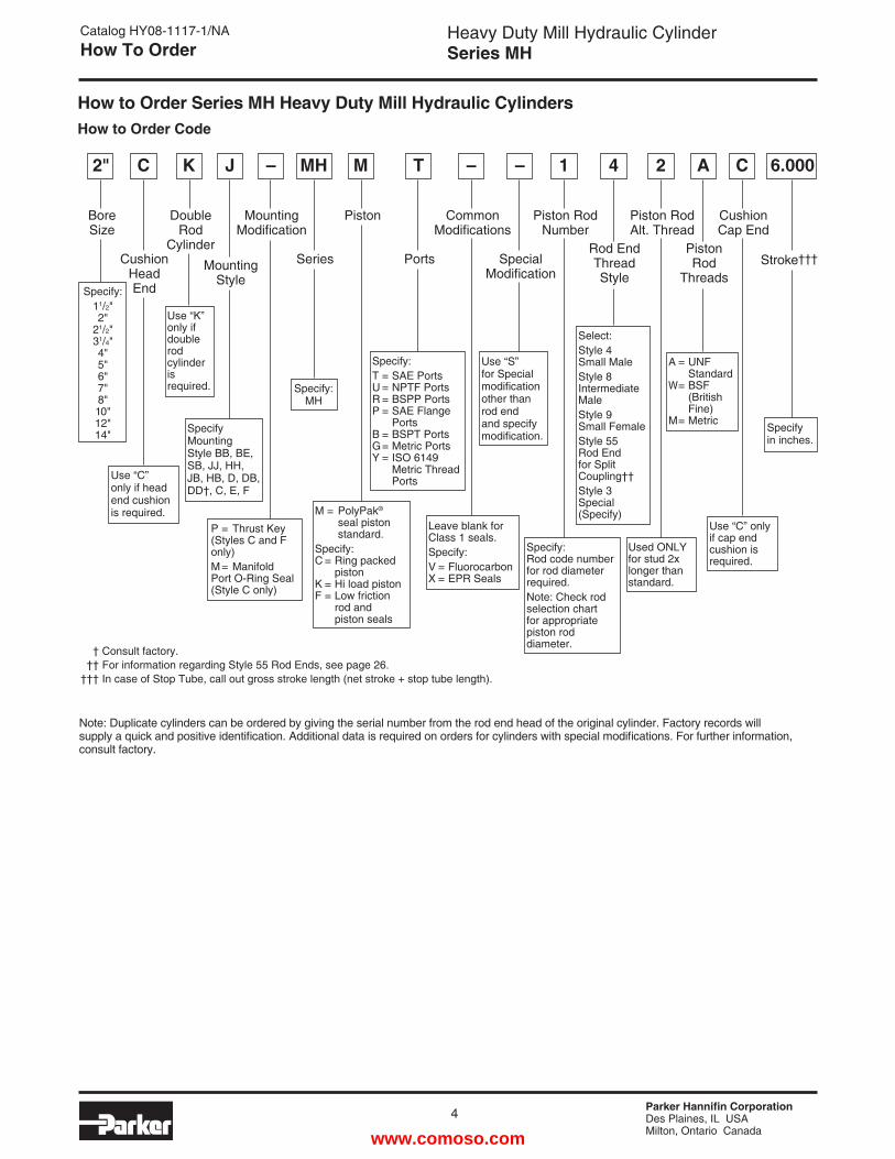
How to Order Series MH Heavy Duty Mill Hydraulic CylindersHow to Order Code
Note: Duplicate cylinders can be ordered by giving the serial number from the rod end head of the original cylinder. Factory records will supply a quick and positive identification. Additional data is required on orders for cylinders with special modifications. For further information, consult factory.
Bore Size
Cushion Head EndSpecify:
11/2"2"
21/2"31/4"4"5"6"7"8"10"12"14"
Use “C” only if head end cushion is required.
2" C
Double Rod
Cylinder
Use “K” only if double rod cylinder is required.
K
Mounting Style
Specify Mounting Style BB, BE, SB, JJ, HH, JB, HB, D, DB, DD†, C, E, F
J
Mounting Modification
P = Thrust Key (Styles C and F only)M = Manifold Port O-Ring Seal (Style C only)
Series
Specify: MH
MH
Piston
M = PolyPak® seal piston standard.Specify: C = Ring packed piston K = Hi load piston F = Low friction rod and piston seals
M
Ports
Specify:T = SAE Ports U = NPTF Ports R = BSPP Ports P = SAE Flange Ports B = BSPT Ports G = Metric Ports Y = ISO 6149 Metric Thread Ports
Common Modifications
Leave blank for Class 1 seals.Specify:V = Fluorocarbon X = EPR Seals
–
SpecialModification
Use “S” for Special modification other than rod end and specify modification.
–
Piston Rod Number
Specify: Rod code number for rod diameter required.Note: Check rod selection chart for appropriate piston rod diameter.
1
Rod End Thread Style
Select:Style 4 Small MaleStyle 8 Intermediate MaleStyle 9 Small FemaleStyle 55 Rod End for Split Coupling††Style 3 Special (Specify)
4
Piston Rod Alt. Thread
Used ONLY for stud 2x longer than standard.
2
Stroke†††
Specify in inches.
6.000– T
Piston Rod
Threads
A
A = UNF Standard W = BSF (British Fine) M = Metric
Cushion Cap End
Use “C” only if cap end cushion is required.
C
† Consult factory. †† For information regarding Style 55 Rod Ends, see page 26. ††† In case of Stop Tube, call out gross stroke length (net stroke + stop tube length).
www.comoso.com
Parker Hannifin CorporationDes Plaines, IL USAMilton, Ontario Canada
Heavy Duty Mill Hydraulic CylinderSeries MH
5
Catalog HY08-1117-1/NASpecifications & Mounting Styles
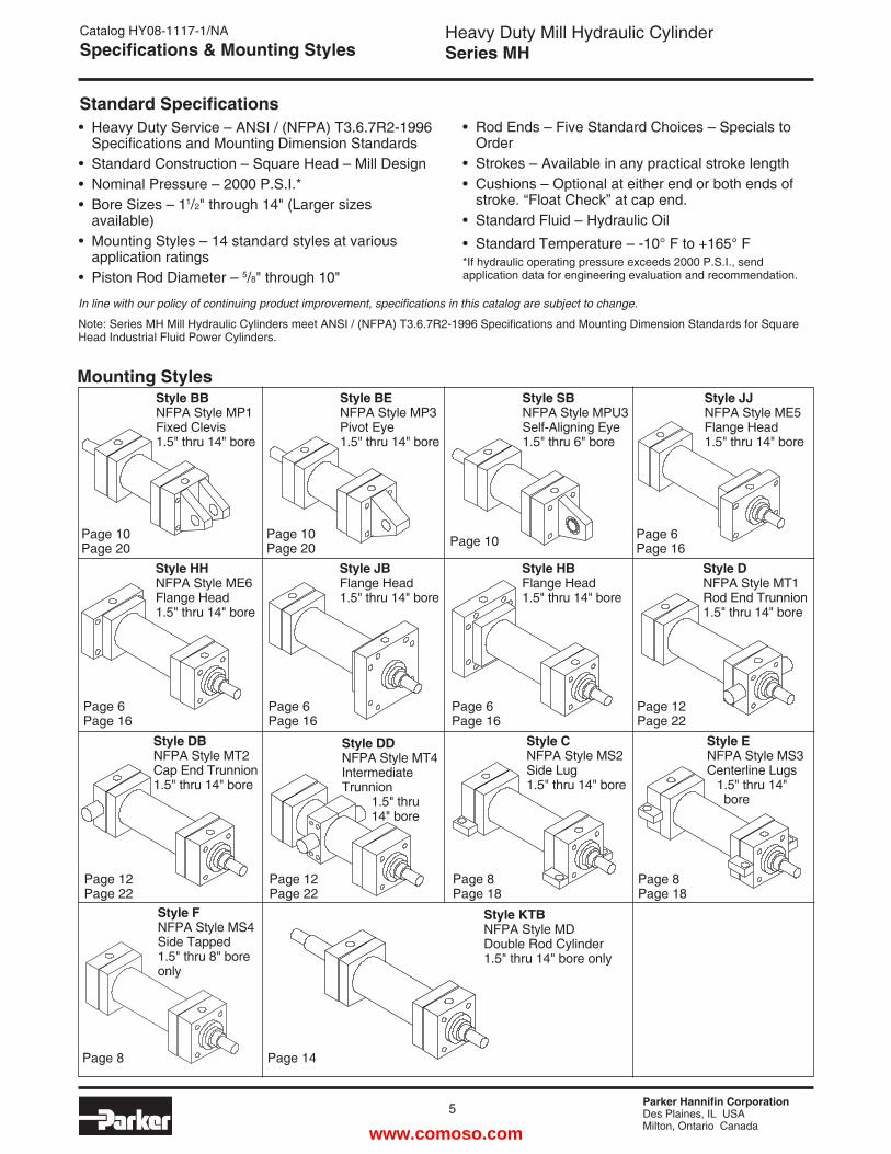
Note: Series MH Mill Hydraulic Cylinders meet ANSI / (NFPA) T3.6.7R2-1996 Specifications and Mounting Dimension Standards for Square Head Industrial Fluid Power Cylinders.
• Heavy Duty Service – ANSI / (NFPA) T3.6.7R2-1996 Specifications and Mounting Dimension Standards• Standard Construction – Square Head – Mill Design• Nominal Pressure – 2000 P.S.I.*• Bore Sizes – 11/2" through 14" (Larger sizes available)• Mounting Styles – 14 standard styles at various application ratings• Piston Rod Diameter – 5/8" through 10"
• Rod Ends – Five Standard Choices – Specials to Order• Strokes – Available in any practical stroke length• Cushions – Optional at either end or both ends of stroke. “Float Check” at cap end.• Standard Fluid – Hydraulic Oil
• Standard Temperature – -10° F to +165° F*If hydraulic operating pressure exceeds 2000 P.S.I., send application data for engineering evaluation and recommendation.
In line with our policy of continuing product improvement, specifications in this catalog are subject to change.
Standard Specifications
Mounting StylesStyle BBNFPA Style MP1Fixed Clevis1.5" thru 14" bore
Page 10 Page 20
Style BENFPA Style MP3Pivot Eye1.5" thru 14" bore
Page 10 Page 20
Style SBNFPA Style MPU3Self-Aligning Eye1.5" thru 6" bore
Page 10
Style JJNFPA Style ME5Flange Head1.5" thru 14" bore
Page 6 Page 16
Style HHNFPA Style ME6Flange Head1.5" thru 14" bore
Page 6 Page 16
Style JBFlange Head1.5" thru 14" bore
Page 6 Page 16
Style HBFlange Head1.5" thru 14" bore
Page 6 Page 16
Style DNFPA Style MT1Rod End Trunnion1.5" thru 14" bore
Page 12 Page 22
Style DBNFPA Style MT2Cap End Trunnion1.5" thru 14" bore
Page 12 Page 22
Style DDNFPA Style MT4Intermediate Trunnion 1.5" thru 14" bore
Page 12 Page 22
Style CNFPA Style MS2Side Lug1.5" thru 14" bore
Page 8 Page 18
Style ENFPA Style MS3Centerline Lugs 1.5" thru 14" bore
Page 8 Page 18
Style FNFPA Style MS4Side Tapped1.5" thru 8" bore only
Page 8
Style KTBNFPA Style MDDouble Rod Cylinder1.5" thru 14" bore only
Page 14
www.comoso.com
Parker Hannifin CorporationDes Plaines, IL USAMilton, Ontario Canada
6
Heavy Duty Mill Hydraulic CylinderSeries MH
RT
RD
RT
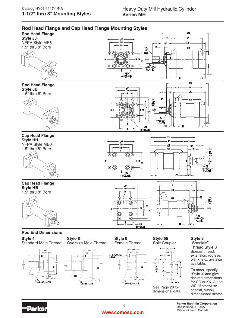
Rod End DimensionsStyle 3“Specials” Thread Style 3Special thread, extension, rod eye, blank, etc., are also available.
To order, specify “Style 3” and give desired dimensions for CC or KK, A and WF. If otherwise special, supply dimensioned sketch.
Catalog HY08-1117-1/NA1-1/2" thru 8" Mounting Styles
Rod Head Flange Style JJNFPA Style ME51.5" thru 8" Bore
Rod Head Flange Style JB1.5" thru 8" Bore
Cap Head Flange Style HHNFPA Style ME61.5" thru 8" Bore
Cap Head Flange Style HB1.5" thru 8" Bore
Rod Head Flange and Cap Head Flange Mounting Styles
Style 55Split Coupler
See Page 26 for dimensional data.
Style 8Oversize Male Thread
Style 4Standard Male Thread
Style 9Female Thread
KB
RD
RT
KB
RD
RTRT
RD
KB
B
WG
KB
AC
AD
AE
AM
AF
RD
V
RT
www.comoso.com
Parker Hannifin CorporationDes Plaines, IL USAMilton, Ontario Canada
Heavy Duty Mill Hydraulic CylinderSeries MH
7
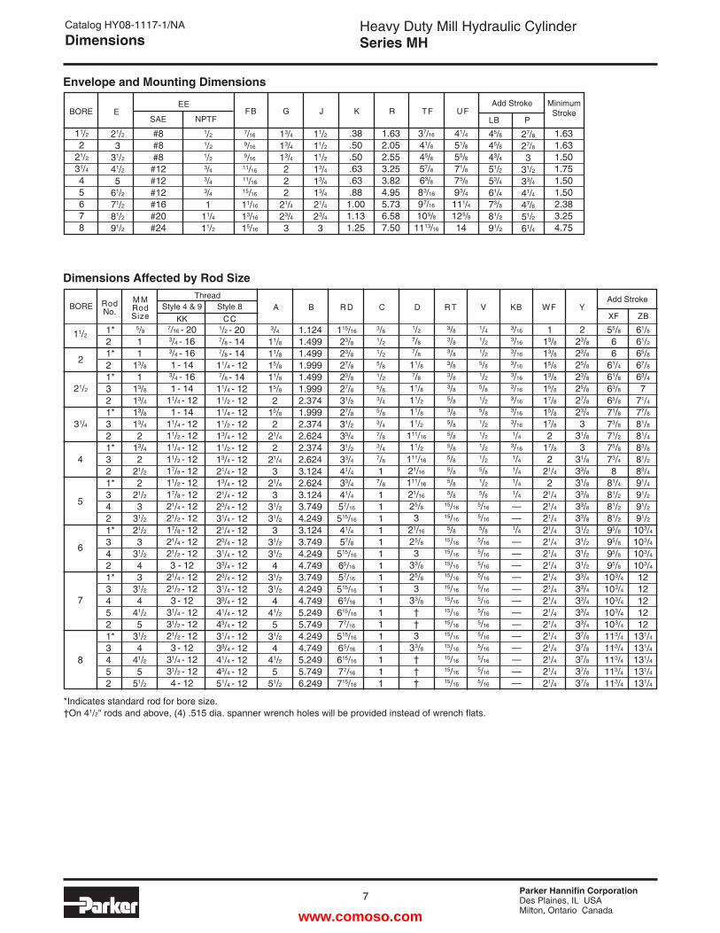
Catalog HY08-1117-1/NADimensions
223/823/825/823/825/827/823/43
31/83
31/833/831/833/833/833/831/231/231/231/233/433/433/433/433/437/837/837/837/837/8
5
6
7
8
BOREM MRod Size
11/2
2
21/2
31/4
4
5/811
13/8
113/813/413/813/42
13/42
21/22
21/23
31/221/23
31/243
31/24
41/25
31/24
41/25
51/2
7/16 - 203/4 - 163/4 - 161 - 14
3/4 - 161 - 14
11/4 - 121 - 14
11/4 - 1211/2 - 1211/4 - 1211/2 - 1217/8 - 1211/2 - 1217/8 - 1221/4 - 1221/2 - 1217/8 - 1221/4 - 1221/2 - 123 - 12
21/4 - 1221/2 - 123 - 12
31/4 - 1231/2 - 1221/2 - 123 - 12
31/4 - 1231/2 - 124 - 12
1/2 - 207/8 - 147/8 - 1411/4 - 127/8 - 1411/4 - 1211/2 - 1211/4 - 1211/2 - 1213/4 - 1211/2 - 1213/4 - 1221/4 - 1213/4 - 1221/4 - 1223/4 - 1231/4 - 1221/4 - 1223/4 - 1231/4 - 1233/4 - 1223/4 - 1231/4 - 1233/4 - 1241/4 - 1243/4 - 1231/4 - 1233/4 - 1241/4 - 1243/4 - 1251/4 - 12
3/411/811/815/811/815/82
15/82
21/42
21/43
21/43
31/231/23
31/231/24
31/231/24
41/25
31/24
41/25
51/2
3/81/21/25/81/25/83/45/83/47/83/47/81
7/811111111111111111
1/27/87/811/87/811/811/211/811/2
111/16
11/2111/16
21/16
111/16
21/16
25/83
21/16
25/83
33/825/83
33/8††3
33/8†††
3/83/83/83/83/83/85/83/85/85/85/85/85/85/85/8
15/16
15/16
5/815/16
15/16
15/16
15/16
15/16
15/16
15/16
15/16
15/16
15/16
15/16
15/16
15/16
1.1241.4991.4991.9991.4991.9992.3741.9992.3742.6242.3742.6243.1242.6243.1243.7494.2493.1243.7494.2494.7493.7494.2494.7495.2495.7494.2494.7495.2495.7496.249
1/41/21/25/81/25/81/25/81/21/21/21/25/81/25/85/16
5/16
5/85/16
5/16
5/16
5/16
5/16
5/16
5/16
5/16
5/16
5/16
5/16
5/16
5/16
3/16
3/16
3/16
3/16
3/16
3/16
3/16
3/16
3/16
1/43/16
1/41/41/41/4——1/4—————————————
A B R D C D R T V KBThread
Style 4 & 9 Style 8 KK CC
113/813/815/813/815/817/815/817/82
17/82
21/42
21/421/421/421/421/421/421/421/421/421/421/421/421/421/421/421/421/4
55/866
61/461/863/865/871/873/871/275/873/48
81/481/281/281/295/895/895/895/8
103/4103/4103/4103/4103/4113/4113/4113/4113/4113/4
61/861/265/867/863/47
71/477/881/881/483/881/283/491/491/291/291/2
103/4103/4103/4103/41212121212
131/4131/4131/4131/4131/4
WF YXF ZB
Add Stroke
115/16
23/823/827/823/827/831/227/831/233/431/233/441/433/441/457/16
515/16
41/457/8
515/16
65/16
57/16
515/16
65/16
615/16
77/16
515/16
65/16
615/16
77/16
715/16
BORE E
21/2
331/2
41/2
561/2
71/2
81/2
91/2
#8#8#8#12#12#12#16#20#24
1/2
1/2
1/2
3/43/43/41
11/4
11/2
11/2
11/2
11/2
13/4
13/4
13/4
21/423/43
.38
.50
.50
.63
.63
.881.001.131.25
1.632.052.553.253.824.955.736.587.50
7/16
9/16
9/16
11/16
11/16
15/16
11/16
13/16
15/16
37/16
41/8
45/8
57/8
63/883/16
97/16
105/81113/16
41/4
51/855/8
71/8
75/893/4
111/4125/814
FB G J K R TF UFEE
SAE NPTF
45/845/843/4
51/253/461/473/881/2
91/2
LB
Add Stroke
13/4
13/4
13/4
222
21/423/43
P
11/2
221/2
31/4
45678
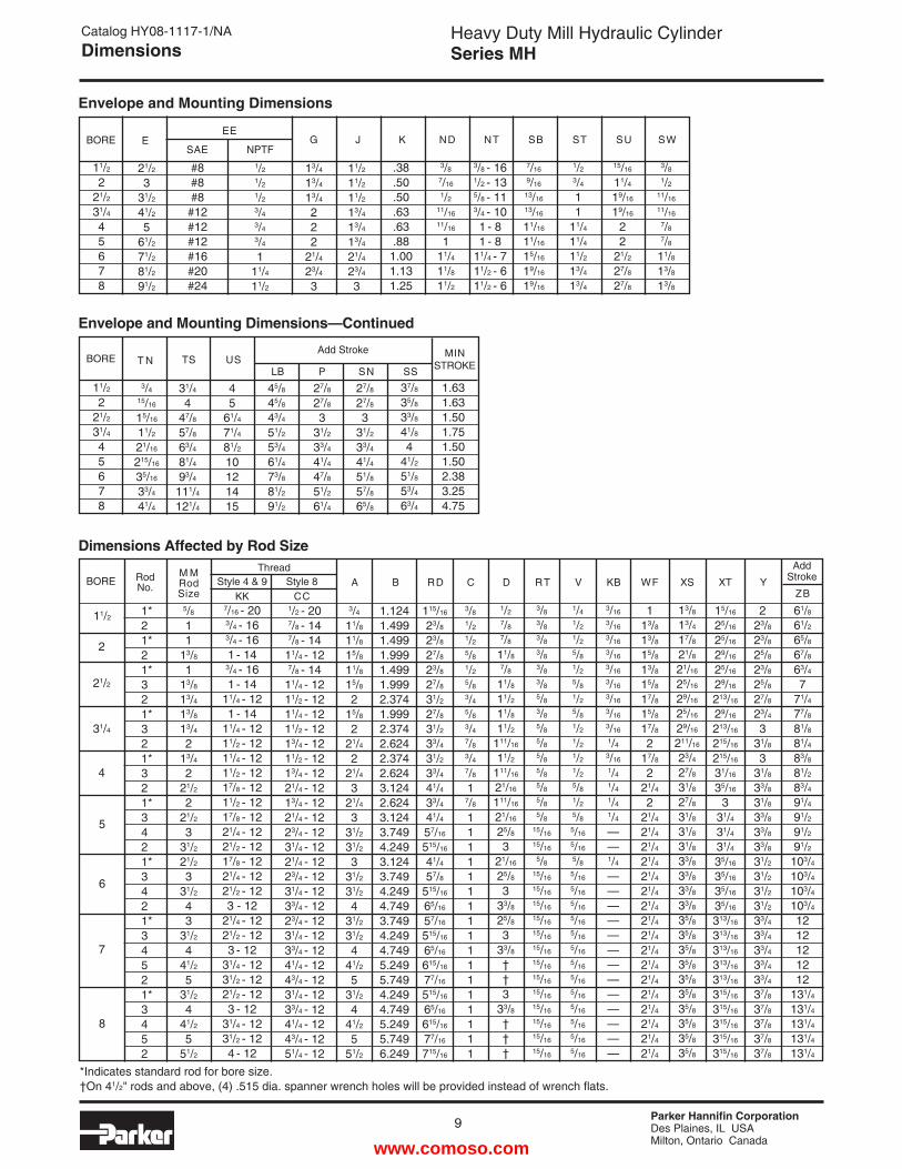
Envelope and Mounting Dimensions
Dimensions Affected by Rod Size
MinimumStroke
1.631.631.501.751.501.502.383.254.75
27/8
27/8
3
31/2
33/441/447/851/261/4
Rod No.
1*21*21*321*321*321*3421*3421*34521*3452
*Indicates standard rod for bore size.†On 41/2" rods and above, (4) .515 dia. spanner wrench holes will be provided instead of wrench flats.
www.comoso.com
Parker Hannifin CorporationDes Plaines, IL USAMilton, Ontario Canada
8
Heavy Duty Mill Hydraulic CylinderSeries MH
E/2 -.005�-.010
E/2 -.005�-.010
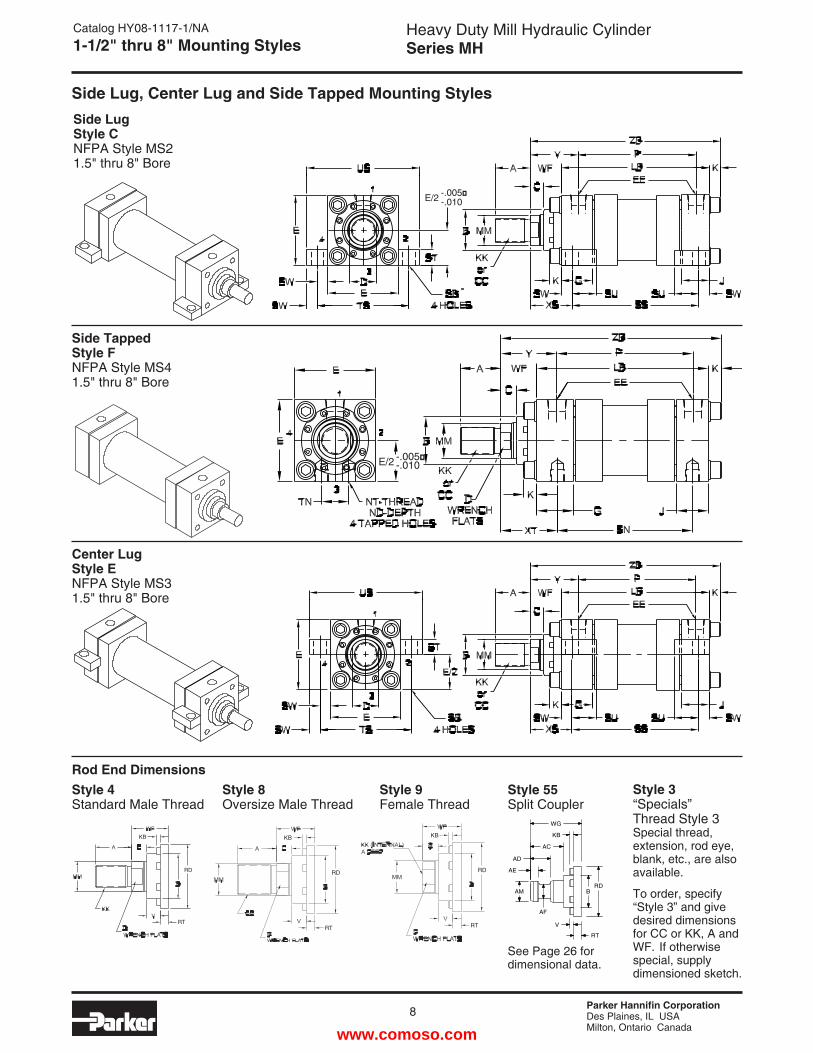
Catalog HY08-1117-1/NA1-1/2" thru 8" Mounting Styles
Side Lug Style CNFPA Style MS21.5" thru 8" Bore
Side Tapped Style FNFPA Style MS41.5" thru 8" Bore
Center Lug Style ENFPA Style MS31.5" thru 8" Bore
Side Lug, Center Lug and Side Tapped Mounting Styles
Rod End DimensionsStyle 3“Specials” Thread Style 3Special thread, extension, rod eye, blank, etc., are also available.
To order, specify “Style 3” and give desired dimensions for CC or KK, A and WF. If otherwise special, supply dimensioned sketch.
Style 55Split Coupler
See Page 26 for dimensional data.
Style 8Oversize Male Thread
Style 4Standard Male Thread
Style 9Female Thread
KB
RD
RT
KB
RD
RTRT
RD
KB
B
WG
KB
AC
AD
AE
AM
AF
RD
V
RT
www.comoso.com
Parker Hannifin CorporationDes Plaines, IL USAMilton, Ontario Canada
Heavy Duty Mill Hydraulic CylinderSeries MH
9
Catalog HY08-1117-1/NADimensions
5
6
7
8
BOREM MRod Size
11/2
2
21/2
31/4
4
5/8
11
13/8
113/8
13/4
13/8
13/4
213/4
221/2
221/2
331/2
21/2
331/2
43
31/2
441/2
531/2
441/2
551/2
7/16 - 203/4 - 163/4 - 161 - 14
3/4 - 161 - 14
11/4 - 121 - 14
11/4 - 1211/2 - 1211/4 - 1211/2 - 1217/8 - 1211/2 - 1217/8 - 1221/4 - 1221/2 - 1217/8 - 1221/4 - 1221/2 - 123 - 12
21/4 - 1221/2 - 123 - 12
31/4 - 1231/2 - 1221/2 - 123 - 12
31/4 - 1231/2 - 124 - 12
1/2 - 207/8 - 147/8 - 1411/4 - 127/8 - 1411/4 - 1211/2 - 1211/4 - 1211/2 - 1213/4 - 1211/2 - 1213/4 - 1221/4 - 1213/4 - 1221/4 - 1223/4 - 1231/4 - 1221/4 - 1223/4 - 1231/4 - 1233/4 - 1223/4 - 1231/4 - 1233/4 - 1241/4 - 1243/4 - 1231/4 - 1233/4 - 1241/4 - 1243/4 - 1251/4 - 12
3/4
11/8
11/8
15/8
11/8
15/8
215/8
221/4
221/4
321/4
331/2
31/2
331/2
31/2
431/2
31/2
441/2
531/2
441/2
551/2
3/8
1/2
1/2
5/8
1/2
5/8
3/4
5/8
3/4
7/8
3/4
7/8
17/8
11111111111111111
1/2
7/8
7/8
11/8
7/8
11/8
11/2
11/8
11/2
111/16
11/2
111/16
21/16
111/16
21/16
25/8
321/16
25/8
333/8
25/8
333/8
††3
33/8
†††
3/8
3/8
3/8
3/8
3/8
3/8
5/8
3/8
5/8
5/8
5/8
5/8
5/8
5/8
5/8
15/16
15/16
5/8
15/16
15/16
15/16
15/16
15/16
15/16
15/16
15/16
15/16
15/16
15/16
15/16
15/16
1.1241.4991.4991.9991.4991.9992.3741.9992.3742.6242.3742.6243.1242.6243.1243.7494.2493.1243.7494.2494.7493.7494.2494.7495.2495.7494.2494.7495.2495.7496.249
1/4
1/2
1/2
5/8
1/2
5/8
1/2
5/8
1/2
1/2
1/2
1/2
5/8
1/2
5/8
5/16
5/16
5/8
5/16
5/16
5/16
5/16
5/16
5/16
5/16
5/16
5/16
5/16
5/16
5/16
5/16
3/16
3/16
3/16
3/16
3/16
3/16
3/16
3/16
3/16
1/4
3/16
1/4
1/4
1/4
1/4
——1/4
—————————————
A B RD C D RT V KBThread
Style 4 & 9 Style 8 KK CC
113/8
13/8
15/8
13/8
15/8
17/8
15/8
17/8
217/8
221/4
221/4
21/4
21/4
21/4
21/4
21/4
21/4
21/4
21/4
21/4
21/4
21/4
21/4
21/4
21/4
21/4
21/4
223/8
23/8
25/8
23/8
25/8
27/8
23/4
331/8
331/8
33/8
31/8
33/8
33/8
33/8
31/2
31/2
31/2
31/2
33/4
33/4
33/4
33/4
33/4
37/8
37/8
37/8
37/8
37/8
61/8
61/2
65/8
67/8
63/4
771/4
77/8
81/8
81/4
83/8
81/2
83/4
91/4
91/2
91/2
91/2
103/4
103/4
103/4
103/4
1212121212
131/4
131/4
131/4
131/4
131/4
WF YZB
Add Stroke
115/16
23/8
23/8
27/8
23/8
27/8
31/2
27/8
31/2
33/4
31/2
33/4
41/4
33/4
41/4
57/16
515/16
41/4
57/8
515/16
65/16
57/16
515/16
65/16
615/16
77/16
515/16
65/16
615/16
77/16
715/16
BORE E
21/2
331/2
41/2
561/2
71/2
81/2
91/2
#8#8#8#12#12#12#16#20#24
1/2
1/2
1/2
3/4
3/4
3/4
111/4
11/2
11/2
11/2
11/2
13/4
13/4
13/4
21/4
23/4
3
.38
.50
.50
.63
.63
.881.001.131.25
3/8
7/16
1/2
11/16
11/16
111/4
11/8
11/2
3/8 - 161/2 - 135/8 - 113/4 - 101 - 81 - 8
11/4 - 711/2 - 611/2 - 6
7/16
9/16
13/16
13/16
11/16
11/16
15/16
19/16
19/16
G J K ND NT SBEE
SAE NPTF
13/4
13/4
13/4
222
21/4
23/4
3
11/2
221/2
31/4
45678
Envelope and Mounting Dimensions
Dimensions Affected by Rod Size
BORE T N
3/4
15/16
15/16
11/2
21/16
215/16
35/16
33/4
41/4
45
61/4
71/4
81/2
10121415
27/8
27/8
3
31/2
33/4
41/4
51/8
57/8
65/8
37/8
35/8
33/8
41/8
4
41/2
51/8
53/4
63/4
1.631.631.501.751.501.502.383.254.75
45/8
45/8
43/4
51/2
53/4
61/4
73/8
81/2
91/2
USLB P SN SS
MINSTROKE
Add Stroke
27/8
27/8
3
31/2
33/4
41/4
47/8
51/2
61/4
11/2
221/2
31/4
45678
Envelope and Mounting Dimensions—Continued
1/2
3/4
1
1
11/4
11/4
11/2
13/4
13/4
15/16
11/4
19/16
19/16
22
21/2
27/8
27/8
3/8
1/2
11/16
11/16
7/8
7/8
11/8
13/8
13/8
ST SU SW
31/4
447/8
57/8
63/4
81/4
93/4
111/4
121/4
TS
13/8
13/4
17/8
21/8
21/16
25/16
29/16
25/16
29/16
211/16
23/4
27/8
31/8
27/8
31/8
31/8
31/8
33/8
33/8
33/8
33/8
35/8
35/8
35/8
35/8
35/8
35/8
35/8
35/8
35/8
35/8
XS
15/16
25/16
25/16
29/16
25/16
29/16
213/16
29/16
213/16
215/16
215/16
31/16
35/16
331/4
31/4
31/4
35/16
35/16
35/16
35/16
313/16
313/16
313/16
313/16
313/16
315/16
315/16
315/16
315/16
315/16
XTRod No.
1*21*21*321*321*321*3421*3421*34521*3452
*Indicates standard rod for bore size.†On 41/2" rods and above, (4) .515 dia. spanner wrench holes will be provided instead of wrench flats.
www.comoso.com
Parker Hannifin CorporationDes Plaines, IL USAMilton, Ontario Canada
10
Heavy Duty Mill Hydraulic CylinderSeries MH
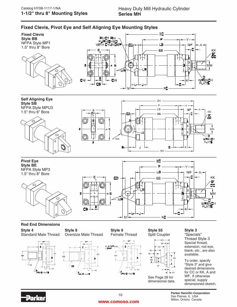
Fixed Clevis Style BBNFPA Style MP11.5" thru 8" Bore
Self Aligning Eye Style SBNFPA Style MPU31.5" thru 6" Bore
Pivot Eye Style BENFPA Style MP31.5" thru 8" Bore
ZH
PLB
XH
Catalog HY08-1117-1/NA1-1/2" thru 8" Mounting Styles
Fixed Clevis, Pivot Eye and Self Aligning Eye Mounting Styles
Rod End DimensionsStyle 3“Specials” Thread Style 3Special thread, extension, rod eye, blank, etc., are also available.
To order, specify “Style 3” and give desired dimensions for CC or KK, A and WF. If otherwise special, supply dimensioned sketch.
Style 55Split Coupler
See Page 26 for dimensional data.
Style 8Oversize Male Thread
Style 4Standard Male Thread
Style 9Female Thread
KB
RD
RT
KB
RD
RTRT
RD
KB
B
WG
KB
AC
AD
AE
AM
AF
RD
V
RT
www.comoso.com
Parker Hannifin CorporationDes Plaines, IL USAMilton, Ontario Canada
Heavy Duty Mill Hydraulic CylinderSeries MH
11
Catalog HY08-1117-1/NADimensions
5
6
7
8
BOREMMRod Size
11/2
2
21/2
31/4
4
5/8
11
13/8
113/8
13/4
13/8
13/4
213/4
221/2
221/2
331/2
21/2
331/2
43
31/2
441/2
531/2
441/2
551/2
7/16 - 203/4 - 163/4 - 161 - 14
3/4 - 161 - 14
11/4 - 121 - 14
11/4 - 1211/2 - 1211/4 - 1211/2 - 1217/8 - 1211/2 - 1217/8 - 1221/4 - 1221/2 - 1217/8 - 1221/4 - 1221/2 - 123 - 12
21/4 - 1221/2 - 123 - 12
31/4 - 1231/2 - 1221/2 - 123 - 12
31/4 - 1231/2 - 124 - 12
1/2 - 207/8 - 147/8 - 1411/4 - 127/8 - 1411/4 - 1211/2 - 1211/4 - 1211/2 - 1213/4 - 1211/2 - 1213/4 - 1221/4 - 1213/4 - 1221/4 - 1223/4 - 1231/4 - 1221/4 - 1223/4 - 1231/4 - 1233/4 - 1223/4 - 1231/4 - 1233/4 - 1241/4 - 1243/4 - 1231/4 - 1233/4 - 1241/4 - 1243/4 - 1251/4 - 12
3/4
11/8
11/8
15/8
11/8
15/8
215/8
221/4
221/4
321/4
331/2
31/2
331/2
31/2
431/2
31/2
441/2
531/2
441/2
551/2
3/8
1/2
1/2
5/8
1/2
5/8
3/4
5/8
3/4
7/8
3/4
7/8
17/8
11111111111111111
1/2
7/8
7/8
11/8
7/8
11/8
11/2
11/8
11/2
111/16
11/2
111/16
21/16
111/16
21/16
25/8
321/16
25/8
333/8
25/8
333/8
††3
33/8
†††
3/8
3/8
3/8
3/8
3/8
3/8
5/8
3/8
5/8
5/8
5/8
5/8
5/8
5/8
5/8
15/16
15/16
5/8
15/16
15/16
15/16
15/16
15/16
15/16
15/16
15/16
15/16
15/16
15/16
15/16
15/16
1.1241.4991.4991.9991.4991.9992.3741.9992.3742.6242.3742.6243.1242.6243.1243.7494.2493.1243.7494.2494.7493.7494.2494.7495.2495.7494.2494.7495.2495.7496.249
1/4
1/2
1/2
5/8
1/2
5/8
1/2
5/8
1/2
1/2
1/2
1/2
5/8
1/2
5/8
5/16
5/16
5/8
5/16
5/16
5/16
5/16
5/16
5/16
5/16
5/16
5/16
5/16
5/16
5/16
5/16
3/16
3/16
3/16
3/16
3/16
3/16
3/16
3/16
3/16
1/4
3/16
1/4
1/4
1/4
1/4
——1/4
—————————————
A B RD C D RT V KBThread**
Style 4 & 9 Style 8 KK CC
113/8
13/8
15/8
13/8
15/8
17/8
15/8
17/8
217/8
221/4
221/4
21/4
21/4
21/4
21/4
21/4
21/4
21/4
21/4
21/4
21/4
21/4
21/4
21/4
21/4
21/4
21/4
223/8
23/8
25/8
23/8
25/8
27/8
23/4
331/8
331/8
33/8
31/8
33/8
33/8
33/8
31/2
31/2
31/2
31/2
33/4
33/4
33/4
33/4
33/4
37/8
37/8
37/8
37/8
37/8
63/8
63/4
71/4
71/2
73/8
75/8
77/8
85/8
87/8
993/4
97/8
101/8
101/2
103/4
103/4
103/4
121/8
121/8
121/8
121/8
133/4
133/4
133/4
133/4
133/4
1515151515
63/8
63/4
71/4
71/2
73/8
75/8
77/8
85/8
87/8
993/4
97/8
101/8
101/2
103/4
103/4
103/4
121/8
121/8
121/8
121/8
——————————
WF YXC XH
Add Stroke
115/16
23/8
23/8
27/8
23/8
27/8
31/2
27/8
31/2
33/4
31/2
33/4
41/4
33/4
41/4
57/16
515/16
41/4
57/8
515/16
65/16
57/16
515/16
65/16
615/16
77/16
515/16
65/16
615/16
77/16
715/16
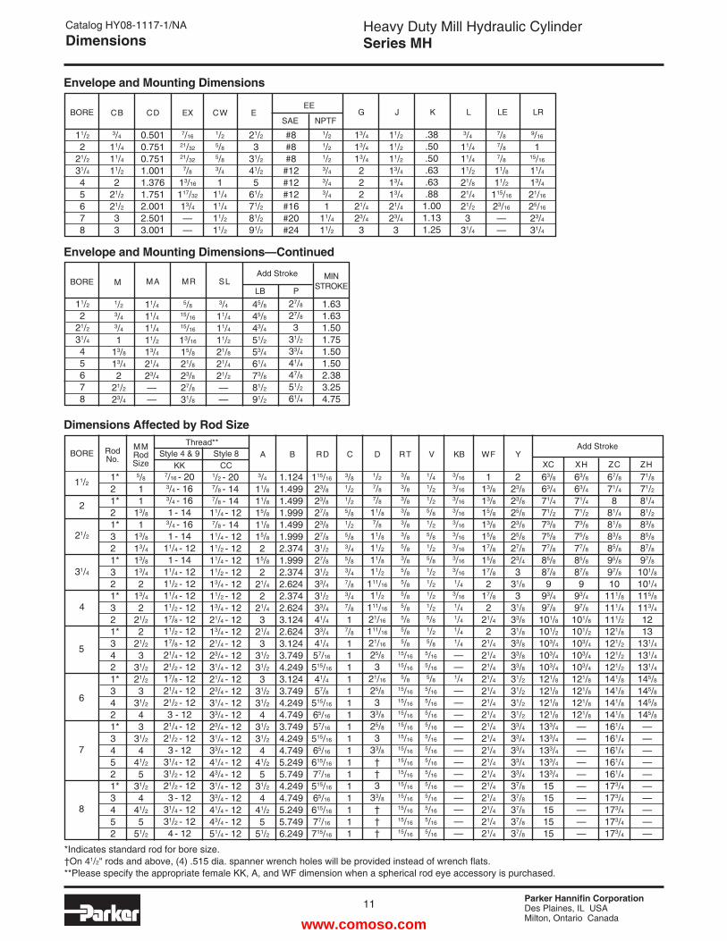
Dimensions Affected by Rod Size
BORE E
21/2
331/2
41/2
561/2
71/2
81/2
91/2
#8#8#8#12#12#12#16#20#24
1/2
1/2
1/2
3/4
3/4
3/4
111/4
11/2
11/2
11/2
11/2
13/4
13/4
13/4
21/4
23/4
3
.38
.50
.50
.63
.63
.881.001.131.25
7/8
7/8
7/8
11/8
11/2
115/16
23/16
——
9/16
115/16
11/4
13/4
21/16
25/16
23/4
31/4
G J K LE LREE
SAE NPTF
13/4
13/4
13/4
222
21/4
23/4
3
11/2
221/2
31/4
45678
Envelope and Mounting Dimensions
BORE M
1/2
3/4
3/4
113/8
13/4
221/2
23/4
5/8
15/16
15/16
13/16
15/8
21/8
23/8
27/8
31/8
1.631.631.501.751.501.502.383.254.75
3/4
11/4
11/4
11/2
21/8
21/4
21/2
——
MR SLLB
MINSTROKE
Add Stroke
11/2
221/2
31/4
45678
Envelope and Mounting Dimensions—Continued
11/4
11/4
11/4
11/2
13/4
21/4
23/4
——
MA
3/4
11/4
11/4
11/2
21/8
21/4
21/2
331/4
LCW
1/2
5/8
5/8
3/4
111/4
11/4
11/2
11/2
EX
7/16
21/32
21/32
7/8
13/16
117/32
13/4
——
CD
0.5010.7510.7511.0011.3761.7512.0012.5013.001
CB
3/4
11/4
11/4
11/2
221/2
21/2
33
45/8
45/8
43/4
51/2
53/4
61/4
73/8
81/2
91/2
P
27/8
27/8
3
31/2
33/4
41/4
47/8
51/2
61/4
67/8
71/4
881/4
81/8
83/8
85/8
95/8
97/8
10111/8
111/4
111/2
121/8
121/2
121/2
121/2
141/8
141/8
141/8
141/8
161/4
161/4
161/4
161/4
161/4
173/4
173/4
173/4
173/4
173/4
71/8
71/2
81/4
81/2
83/8
85/8
87/8
97/8
101/8
101/4
115/8
113/4
1213
131/4
131/4
131/4
145/8
145/8
145/8
145/8
——————————
ZC ZH
RodNo.
1*21*21*321*321*321*3421*3421*34521*3452
*Indicates standard rod for bore size.†On 41/2" rods and above, (4) .515 dia. spanner wrench holes will be provided instead of wrench flats. **Please specify the appropriate female KK, A, and WF dimension when a spherical rod eye accessory is purchased.
www.comoso.com
Parker Hannifin CorporationDes Plaines, IL USAMilton, Ontario Canada
12
Heavy Duty Mill Hydraulic CylinderSeries MH
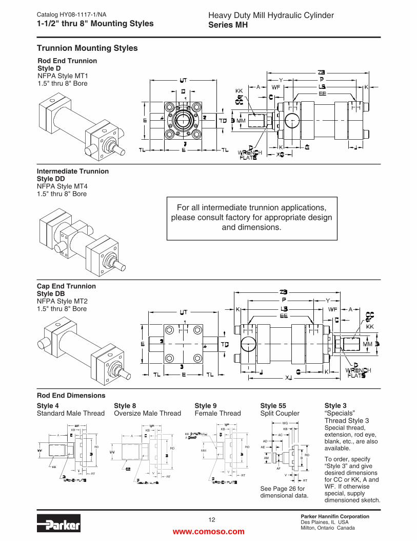
Rod End Trunnion Style DNFPA Style MT11.5" thru 8" Bore
Intermediate Trunnion Style DDNFPA Style MT41.5" thru 8" Bore
Cap End Trunnion Style DBNFPA Style MT21.5" thru 8" Bore
Catalog HY08-1117-1/NA1-1/2" thru 8" Mounting Styles
Trunnion Mounting Styles
Rod End DimensionsStyle 3“Specials” Thread Style 3Special thread, extension, rod eye, blank, etc., are also available.
To order, specify “Style 3” and give desired dimensions for CC or KK, A and WF. If otherwise special, supply dimensioned sketch.
Style 55Split Coupler
See Page 26 for dimensional data.
Style 8Oversize Male Thread
Style 4Standard Male Thread
Style 9Female Thread
KB
RD
RT
KB
RD
RTRT
RD
KB
B
WG
KB
AC
AD
AE
AM
AF
RD
V
RT
For all intermediate trunnion applications, please consult factory for appropriate design
and dimensions.
www.comoso.com
Parker Hannifin CorporationDes Plaines, IL USAMilton, Ontario Canada
Heavy Duty Mill Hydraulic CylinderSeries MH
13
Catalog HY08-1117-1/NADimensions
5
6
7
8
BOREM MRod Size
11/2
2
21/2
31/4
4
5/8
11
13/8
113/8
13/4
13/8
13/4
213/4
221/2
221/2
331/2
21/2
331/2
43
31/2
441/2
531/2
441/2
551/2
7/16 - 203/4 - 163/4 - 161 - 14
3/4 - 161 - 14
11/4 - 121 - 14
11/4 - 1211/2 - 1211/4 - 1211/2 - 1217/8 - 1211/2 - 1217/8 - 1221/4 - 1221/2 - 1217/8 - 1221/4 - 1221/2 - 123 - 12
21/4 - 1221/2 - 123 - 12
31/4 - 1231/2 - 1221/2 - 123 - 12
31/4 - 1231/2 - 124 - 12
1/2 - 207/8 - 147/8 - 1411/4 - 127/8 - 1411/4 - 1211/2 - 1211/4 - 1211/2 - 1213/4 - 1211/2 - 1213/4 - 1221/4 - 1213/4 - 1221/4 - 1223/4 - 1231/4 - 1221/4 - 1223/4 - 1231/4 - 1233/4 - 1223/4 - 1231/4 - 1233/4 - 1241/4 - 1243/4 - 1231/4 - 1233/4 - 1241/4 - 1243/4 - 1251/4 - 12
3/4
11/8
11/8
15/8
11/8
15/8
215/8
221/4
221/4
321/4
331/2
31/2
331/2
31/2
431/2
31/2
441/2
531/2
441/2
551/2
3/8
1/2
1/2
5/8
1/2
5/8
3/4
5/8
3/4
7/8
3/4
7/8
17/8
11111111111111111
1/2
7/8
7/8
11/8
7/8
11/8
11/2
11/8
11/2
111/16
11/2
111/16
21/16
111/16
21/16
25/8
321/16
25/8
333/8
25/8
333/8
††3
33/8
†††
3/8
3/8
3/8
3/8
3/8
3/8
5/8
3/8
5/8
5/8
5/8
5/8
5/8
5/8
5/8
15/16
15/16
5/8
15/16
15/16
15/16
15/16
15/16
15/16
15/16
15/16
15/16
15/16
15/16
15/16
15/16
1.1241.4991.4991.9991.4991.9992.3741.9992.3742.6242.3742.6243.1242.6243.1243.7494.2493.1243.7494.2494.7493.7494.2494.7495.2495.7494.2494.7495.2495.7496.249
1/4
1/2
1/2
5/8
1/2
5/8
1/2
5/8
1/2
1/2
1/2
1/2
5/8
1/2
5/8
5/16
5/16
5/8
5/16
5/16
5/16
5/16
5/16
5/16
5/16
5/16
5/16
5/16
5/16
5/16
5/16
3/16
3/16
3/16
3/16
3/16
3/16
3/16
3/16
3/16
1/4
3/16
1/4
1/4
1/4
1/4
——1/4
—————————————
A B RD C D RT V KBThread
Style 4 & 9 Style 8 KK CC
113/8
13/8
15/8
13/8
15/8
17/8
15/8
17/8
217/8
221/4
221/4
21/4
21/4
21/4
21/4
21/4
21/4
21/4
21/4
21/4
21/4
21/4
21/4
21/4
21/4
21/4
21/4
223/8
23/8
25/8
23/8
25/8
27/8
23/4
331/8
331/8
33/8
31/8
33/8
33/8
33/8
31/2
31/2
31/2
31/2
33/4
33/4
33/4
33/4
33/4
37/8
37/8
37/8
37/8
37/8
47/8
51/4
51/4
51/2
53/8
55/8
57/8
61/4
61/2
65/8
63/4
67/8
71/8
73/8
75/8
75/8
75/8
83/8
83/8
83/8
83/8
93/8
93/8
93/8
93/8
93/8
101/4
101/4
101/4
101/4
101/4
61/8
61/2
65/8
67/8
63/4
771/4
77/8
81/8
81/4
83/8
81/2
83/4
91/4
91/2
91/2
91/2
103/4
103/4
103/4
103/4
1212121212
131/4
131/4
131/4
131/4
131/4
WF YXJ ZB
Add Stroke
115/16
23/8
23/8
27/8
23/8
27/8
31/2
27/8
31/2
33/4
31/2
33/4
41/4
33/4
41/4
57/16
515/16
41/4
57/8
515/16
65/16
57/16
515/16
65/16
615/16
77/16
515/16
65/16
615/16
77/16
715/16
Dimensions Affected by Rod Size
17/8
21/4
21/4
21/2
21/4
21/2
23/4
25/8
27/8
327/8
331/4
331/4
31/4
31/4
33/8
33/8
33/8
33/8
35/8
35/8
35/8
35/8
35/8
33/4
33/4
33/4
33/4
33/4
XG
BORE BD
11/4
11/2
11/2
22233
31/2
#8#8#8#12#12#12#16#20#24
1/2
1/2
1/2
3/4
3/4
3/4
111/4
11/2
11/2
11/2
11/2
13/4
13/4
13/4
21/4
23/4
3
.38
.50
.50
.63
.63
.881.001.131.25
G J KEE
SAE NPTF
13/4
13/4
13/4
222
21/4
23/4
3
11/2
221/2
31/4
45678
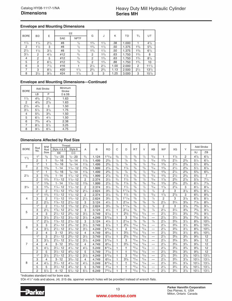
Envelope and Mounting Dimensions
BORE
11/2
221/2
31/4
45678
Envelope and Mounting Dimensions—Continued
E
21/2
331/2
41/2
561/2
71/2
81/2
91/2
1.0001.3751.3751.7501.7501.7502.0002.5003.000
1
13/8
13/8
13/4
13/4
13/4
221/2
3
TD TL
41/2
53/4
61/4
881/2
10111/2
131/2
151/2
UT
45/8
45/8
43/4
51/2
53/4
61/4
73/8
81/2
91/2
27/8
27/8
3
31/2
33/4
41/4
47/8
51/2
61/4
LB
Add Stroke
P
MinimumStrokeD & DB
1.631.631.501.751.501.502.383.254.75
Rod No.
1*21*21*321*321*321*3421*3421*34521*3452
*Indicates standard rod for bore size.†On 41/2" rods and above, (4) .515 dia. spanner wrench holes will be provided instead of wrench flats.
www.comoso.com
Parker Hannifin CorporationDes Plaines, IL USAMilton, Ontario Canada
14
Heavy Duty Mill Hydraulic CylinderSeries MH
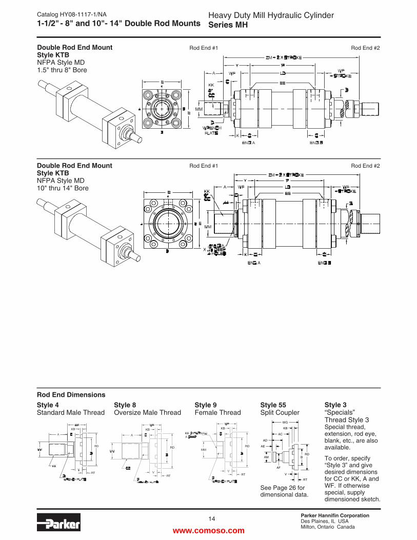
Double Rod End Mount Style KTBNFPA Style MD1.5" thru 8" Bore
Double Rod End Mount Style KTBNFPA Style MD10" thru 14" Bore
Catalog HY08-1117-1/NA1-1/2" - 8" and 10"- 14" Double Rod Mounts
MM
Rod End DimensionsStyle 3“Specials” Thread Style 3Special thread, extension, rod eye, blank, etc., are also available.
To order, specify “Style 3” and give desired dimensions for CC or KK, A and WF. If otherwise special, supply dimensioned sketch.
Style 55Split Coupler
See Page 26 for dimensional data.
Style 8Oversize Male Thread
Style 4Standard Male Thread
Style 9Female Thread
KB
RD
RT
KB
RD
RTRT
RD
KB
B
WG
KB
AC
AD
AE
AM
AF
RD
V
RT
Rod End #1 Rod End #2
Rod End #1 Rod End #2
www.comoso.com
Parker Hannifin CorporationDes Plaines, IL USAMilton, Ontario Canada
Heavy Duty Mill Hydraulic CylinderSeries MH
15
Catalog HY08-1117-1/NADimensions
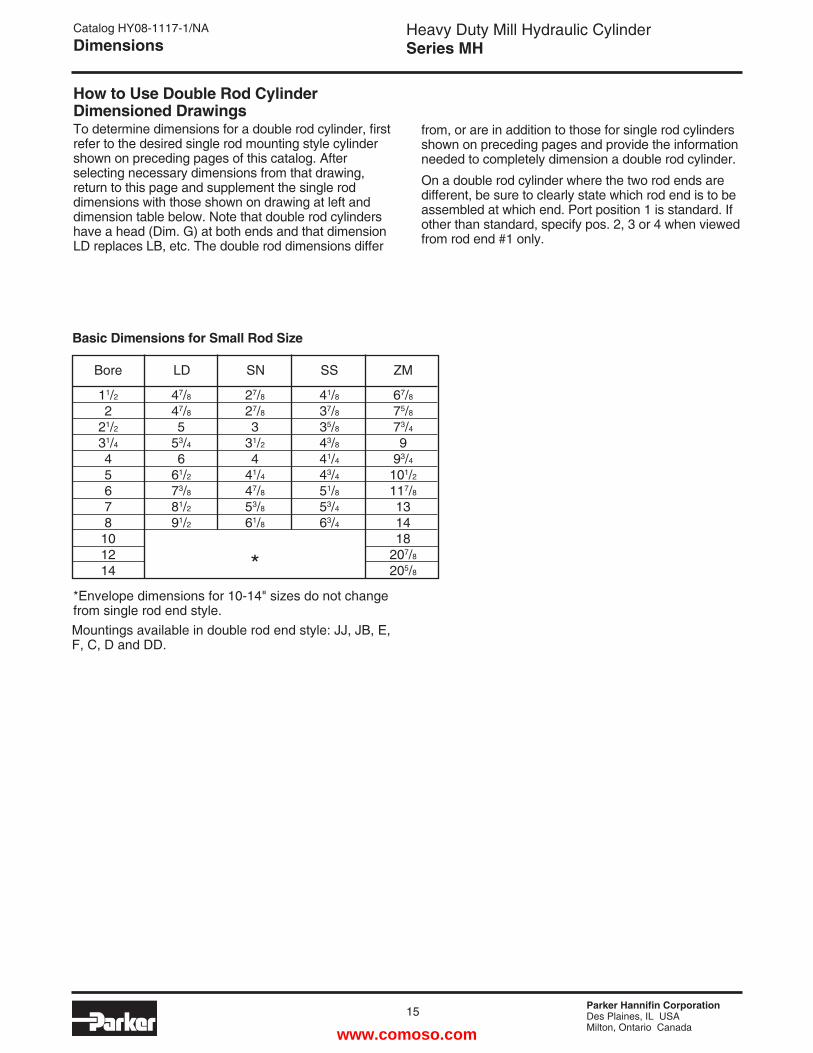
How to Use Double Rod Cylinder Dimensioned DrawingsTo determine dimensions for a double rod cylinder, first refer to the desired single rod mounting style cylinder shown on preceding pages of this catalog. After selecting necessary dimensions from that drawing, return to this page and supplement the single rod dimensions with those shown on drawing at left and dimension table below. Note that double rod cylinders have a head (Dim. G) at both ends and that dimension LD replaces LB, etc. The double rod dimensions differ
from, or are in addition to those for single rod cylinders shown on preceding pages and provide the information needed to completely dimension a double rod cylinder.
On a double rod cylinder where the two rod ends are different, be sure to clearly state which rod end is to be assembled at which end. Port position 1 is standard. If other than standard, specify pos. 2, 3 or 4 when viewed from rod end #1 only.
Basic Dimensions for Small Rod Size
Bore LD SN SS ZM
11/2
221/2
31/4
45678101214
47/8
47/8
553/4
661/2
73/8
81/2
91/2
27/8
27/8
331/2
441/4
47/8
53/8
61/8
*
41/8
37/8
35/8
43/8
41/4
43/4
51/8
53/4
63/4
67/8
75/8
73/4
993/4
101/2
117/8
131418
207/8
205/8
Mountings available in double rod end style: JJ, JB, E, F, C, D and DD.
*Envelope dimensions for 10-14" sizes do not change from single rod end style.
www.comoso.com
Parker Hannifin CorporationDes Plaines, IL USAMilton, Ontario Canada
16
Heavy Duty Mill Hydraulic CylinderSeries MH
EB8 HOLES
EB RT
RD
RT
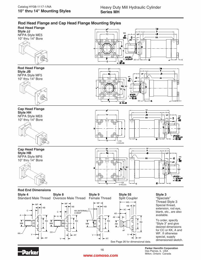
Catalog HY08-1117-1/NA10" thru 14" Mounting Styles
Rod Head Flange Style JJNFPA Style ME510" thru 14" Bore
Rod Head Flange Style JBNFPA Style MF510" thru 14" Bore
Cap Head Flange Style HHNFPA Style ME610" thru 14" Bore
FB4 HOLES
Cap Head Flange Style HBNFPA Style MF610" thru 14" Bore
Rod Head Flange and Cap Head Flange Mounting Styles
Rod End DimensionsStyle 55Split Coupler
Style 8Oversize Male Thread
Style 9Female Thread
Style 3“Specials” Thread Style 3Special thread, extension, rod eye, blank, etc., are also available.
To order, specify “Style 3” and give desired dimensions for CC or KK, A and WF. If otherwise special, supply dimensioned sketch.
Style 4Standard Male Thread
RDB
WF
KBC
MM
V
RT
WF
KB
C
A
MM
CC
V
RT
RDB
WF
KB
C
A
MM
V
RT
KK
KK (INTERNAL)A DEEP
RT
V
RD
AF
AM
AE
AD
AC
KB
WG
BBRD
See Page 26 for dimensional data.
www.comoso.com
Parker Hannifin CorporationDes Plaines, IL USAMilton, Ontario Canada
Heavy Duty Mill Hydraulic CylinderSeries MH
17
Catalog HY08-1117-1/NADimensions
BOREM MRod Size
10
12
14
41/2
551/2
751/2
787810
31/4 - 1231/2 - 124 - 124 - 124 - 124 - 12
41/2 - 124 - 12
41/2 - 1271/4 - 12
41/4 - 1243/4 - 1251/4 - 1251/2 - 1251/4 - 1251/2 - 126 - 12
51/2 - 126 - 12
—
41/2
551/2
51/2
51/2
51/2
851/2
810
11111
11/4
111/4
11
15/16
15/16
15/16
15/16
15/16
15/16
15/16
15/16
15/16
15/8
11
11/4
11/4
11/4
11/4
11/2
11/4
11/2
5/16
5.2495.7496.2497.7496.2497.7498.7497.7498.74910.749
215/16
33/16
33/16
31/2
33/16
31/2
431/2
441/2
43/4
55
55/16
53/8
511/16
63/16
57/8
63/8
67/8
A B RD C RT V WF YThread
Style 4 & 9 Style 8 KK CC
151/16
155/16
155/16
155/8
1711/16
18181/2
191/8
195/8
201/8
1611/32
1619/32
1619/32
1629/32
193/32
1913/32
1929/32
2017/32
211/32
2117/32
XF ZB
Add Stroke
615/16
77/16
715/16
97/8
715/16
97/8
1015/16
97/8
1015/16
14
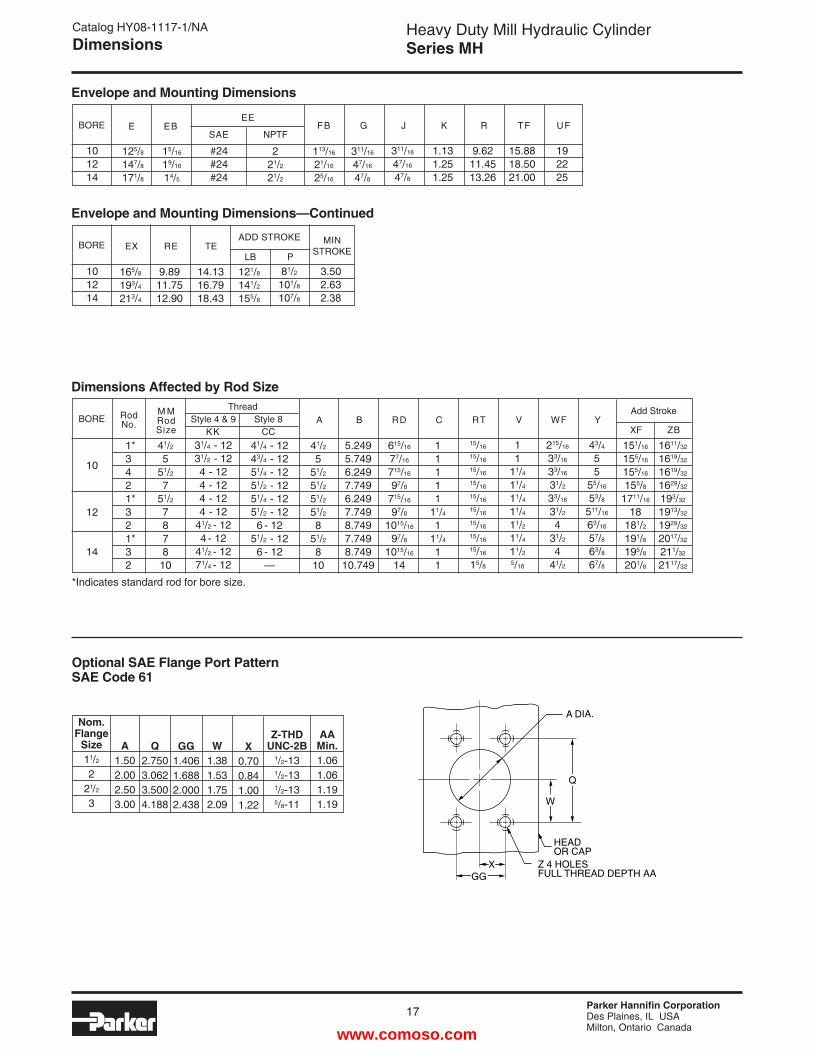
BORE E
125/8
147/8
171/8
#24#24#24
221/2
21/2
311/16
47/16
47/8
311/16
47/16
47/8
1.131.251.25
9.6211.4513.26
15.8818.5021.00
FB G J K R TFEE
SAE NPTF
113/16
21/16
25/16
101214
Envelope and Mounting Dimensions
Dimensions Affected by Rod Size
BORE
121/8
141/2
155/8
81/2
101/8
107/8
3.502.632.38
9.8911.7512.90
LB P
MINSTROKE
ADD STROKE
14.1316.7918.43
101214
Envelope and Mounting Dimensions—Continued
192225
UF
165/8
193/4
213/4
EX
EB
15/16
19/16
14/5
TERE
Optional SAE Flange Port PatternSAE Code 61
Nom.Flange
Size11/2
221/2
3
A1.502.002.503.00
Q2.7503.0623.5004.188
GG1.4061.6882.0002.438
W1.381.531.752.09
X0.700.841.001.22
AA Min.1.061.061.191.19
Z-THDUNC-2B
1/2-131/2-131/2-135/8-11 W
HEADOR CAP
Z 4 HOLESFULL THREAD DEPTH AA
A DIA.
Q
XGG
RodNo.
1*3421*321*32
*Indicates standard rod for bore size.
www.comoso.com
Parker Hannifin CorporationDes Plaines, IL USAMilton, Ontario Canada
18
Heavy Duty Mill Hydraulic CylinderSeries MH
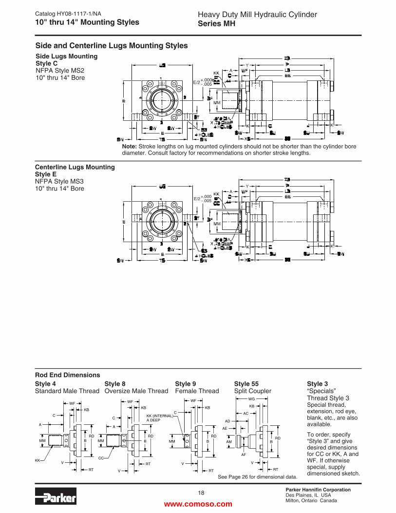
Side Lugs Mounting Style CNFPA Style MS210" thru 14" Bore
Centerline Lugs Mounting Style ENFPA Style MS310" thru 14" Bore
Catalog HY08-1117-1/NA10" thru 14" Mounting Styles
E/2 +.000 - .005
E/2+.000� - .005
Side and Centerline Lugs Mounting Styles
Note: Stroke lengths on lug mounted cylinders should not be shorter than the cylinder bore diameter. Consult factory for recommendations on shorter stroke lengths.
Rod End DimensionsStyle 55Split Coupler
Style 8Oversize Male Thread
Style 9Female Thread
Style 3“Specials” Thread Style 3Special thread, extension, rod eye, blank, etc., are also available.
To order, specify “Style 3” and give desired dimensions for CC or KK, A and WF. If otherwise special, supply dimensioned sketch.
Style 4Standard Male Thread
RDB
WF
KBC
MM
V
RT
WF
KB
C
A
MM
CC
V
RT
RDB
WF
KB
C
A
MM
V
RT
KK
KK (INTERNAL)A DEEP
RT
V
RD
AF
AM
AE
AD
AC
KB
WG
BBRD
See Page 26 for dimensional data.
www.comoso.com
Parker Hannifin CorporationDes Plaines, IL USAMilton, Ontario Canada
Heavy Duty Mill Hydraulic CylinderSeries MH
19
Catalog HY08-1117-1/NADimensions
BOREMMRod Size
10
12
14
41/2
551/2
751/2
787810
31/4 - 1231/2 - 124 - 124 - 124 - 124 - 12
41/2 - 124 - 12
41/2 - 1271/4 - 12
41/4 - 1243/4 - 1251/4 - 1251/2 - 1251/4 - 1251/2 - 126 - 12
51/2 - 126 - 12
—
41/2
551/2
51/2
51/2
51/2
851/2
810
11111
11/4
111/4
11
15/16
15/16
15/16
15/16
15/16
15/16
15/16
15/16
15/16
15/8
11
11/4
11/4
11/4
11/4
11/2
11/4
11/2
5/16
5.2495.7496.2497.7496.2497.7498.7497.7498.74910.749
215/16
33/16
33/16
31/2
33/16
31/2
431/2
441/2
43/4
55
55/16
53/8
511/16
63/16
57/8
63/8
67/8
A B RD C RT V WF YThread
Style 4 & 9 Style 8 KK CC
49/16
413/16
413/16
51/8
53/16
51/2
653/4
61/4
63/4
1611/32
1619/32
1619/32
1629/32
193/32
1913/32
1929/32
2017/32
211/32
2117/32
ZB
Add Stroke
615/16
77/16
715/16
97/8
715/16
97/8
1015/16
97/8
1015/16
14
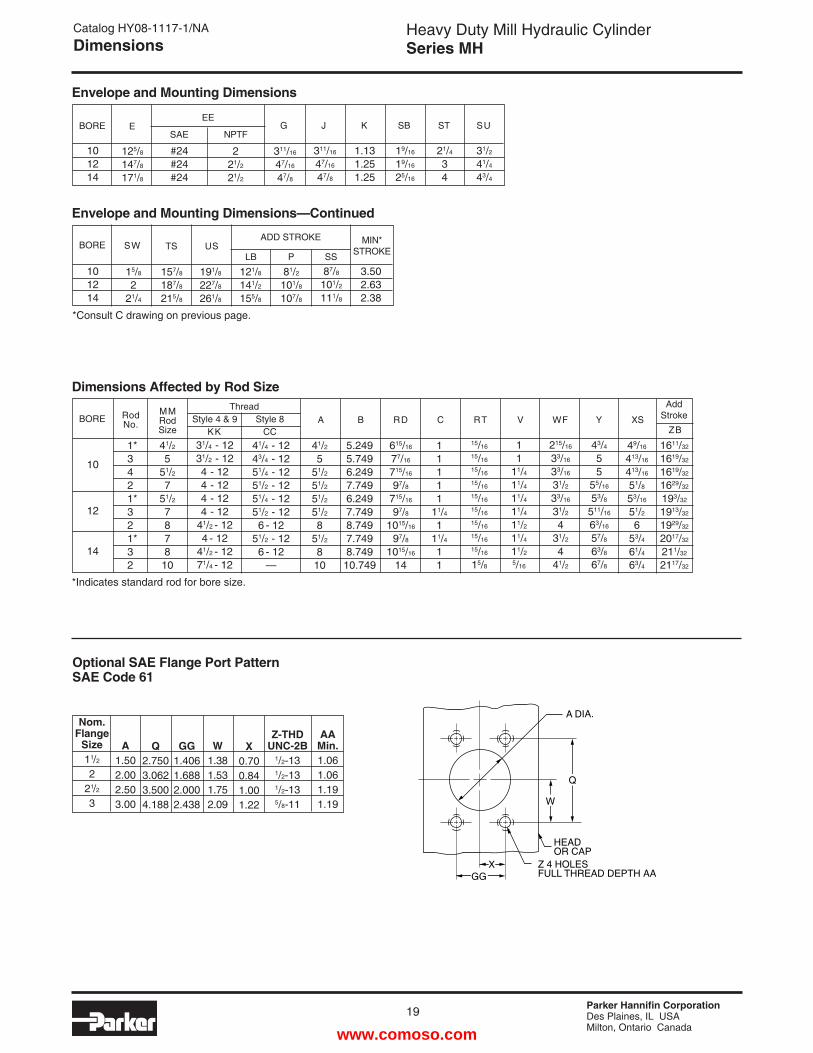
BORE E
125/8
147/8
171/8
#24#24#24
221/2
21/2
311/16
47/16
47/8
311/16
47/16
47/8
1.131.251.25
19/16
19/16
25/16
21/4
34
G J K SB STEE
SAE NPTF
101214
Envelope and Mounting Dimensions
Dimensions Affected by Rod Size
BORE SW
15/8
221/4
191/8
227/8
261/8
81/2
101/8
107/8
87/8
101/2
111/8
3.502.632.38
121/8
141/2
155/8
USP SS
MIN*STROKE
ADD STROKE
101214
Envelope and Mounting Dimensions—Continued
31/2
41/4
43/4
SU
157/8
187/8
215/8
TS
Optional SAE Flange Port PatternSAE Code 61
LB
XS
Nom.Flange
Size11/2
221/2
3
A1.502.002.503.00
Q2.7503.0623.5004.188
GG1.4061.6882.0002.438
W1.381.531.752.09
X0.700.841.001.22
AA Min.1.061.061.191.19
Z-THDUNC-2B
1/2-131/2-131/2-135/8-11
*Consult C drawing on previous page.
W
HEADOR CAP
Z 4 HOLESFULL THREAD DEPTH AA
A DIA.
Q
XGG
RodNo.
1*3421*321*32
*Indicates standard rod for bore size.
www.comoso.com
Parker Hannifin CorporationDes Plaines, IL USAMilton, Ontario Canada
20
Heavy Duty Mill Hydraulic CylinderSeries MH
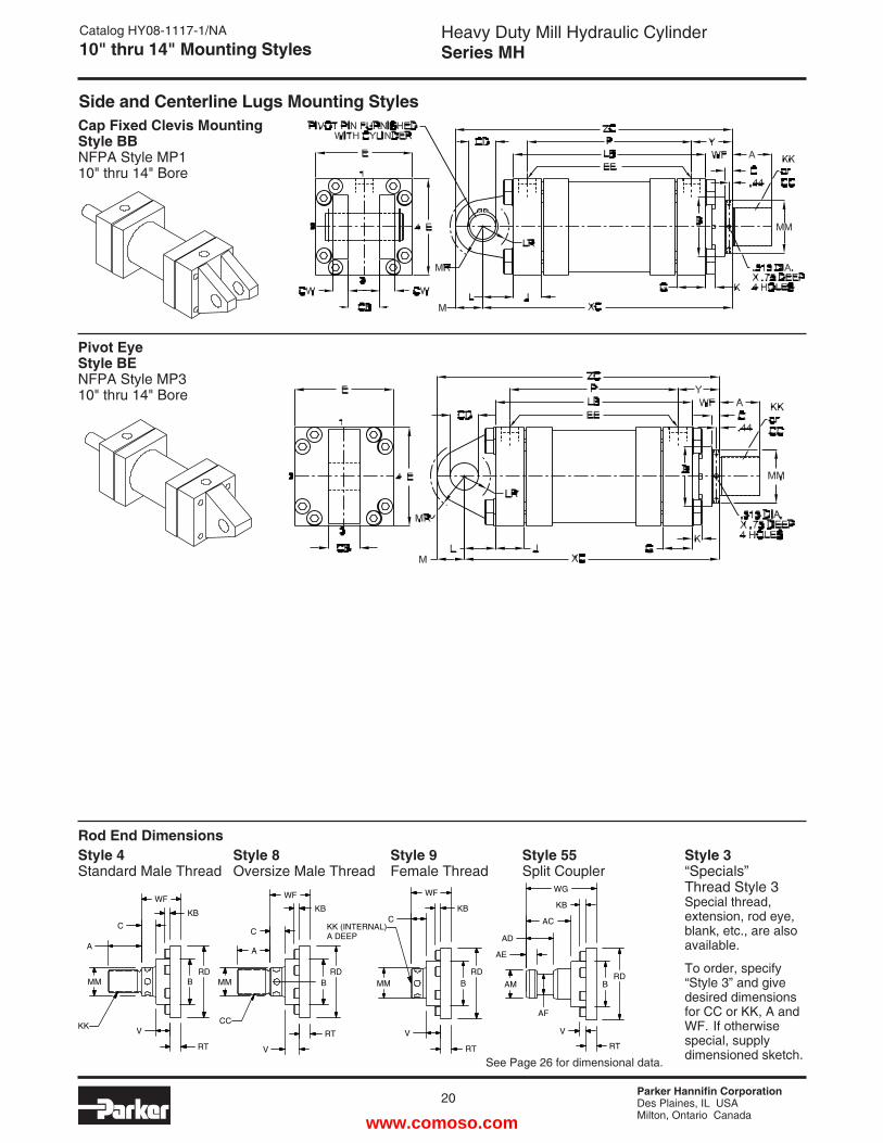
Cap Fixed Clevis Mounting Style BBNFPA Style MP110" thru 14" Bore
Pivot Eye Style BENFPA Style MP310" thru 14" Bore
Catalog HY08-1117-1/NA10" thru 14" Mounting Styles
Side and Centerline Lugs Mounting Styles
Rod End DimensionsStyle 55Split Coupler
Style 8Oversize Male Thread
Style 9Female Thread
Style 3“Specials” Thread Style 3Special thread, extension, rod eye, blank, etc., are also available.
To order, specify “Style 3” and give desired dimensions for CC or KK, A and WF. If otherwise special, supply dimensioned sketch.
Style 4Standard Male Thread
RDB
WF
KBC
MM
V
RT
WF
KB
C
A
MM
CC
V
RT
RDB
WF
KB
C
A
MM
V
RT
KK
KK (INTERNAL)A DEEP
RT
V
RD
AF
AM
AE
AD
AC
KB
WG
BBRD
See Page 26 for dimensional data.
www.comoso.com
Parker Hannifin CorporationDes Plaines, IL USAMilton, Ontario Canada
Heavy Duty Mill Hydraulic CylinderSeries MH
21
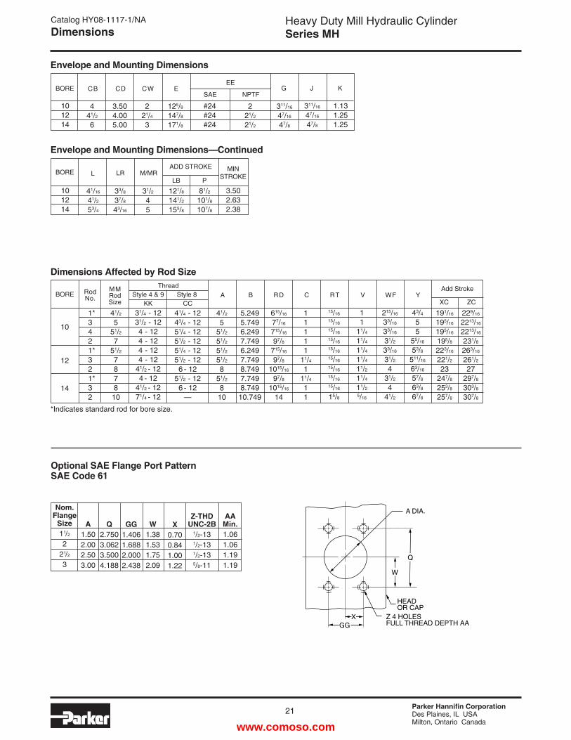
Catalog HY08-1117-1/NADimensions
BOREMMRod Size
10
12
14
41/2
551/2
751/2
787810
31/4 - 1231/2 - 124 - 124 - 124 - 124 - 12
41/2 - 124 - 12
41/2 - 1271/4 - 12
41/4 - 1243/4 - 1251/4 - 1251/2 - 1251/4 - 1251/2 - 126 - 12
51/2 - 126 - 12
—
41/2
551/2
51/2
51/2
51/2
851/2
810
11111
11/4
111/4
11
15/16
15/16
15/16
15/16
15/16
15/16
15/16
15/16
15/16
15/8
11
11/4
11/4
11/4
11/4
11/2
11/4
11/2
5/16
5.2495.7496.2497.7496.2497.7498.7497.7498.74910.749
215/16
33/16
33/16
31/2
33/16
31/2
431/2
441/2
43/4
55
55/16
53/8
511/16
63/16
57/8
63/8
67/8
A B RD C RT V WF YThread
Style 4 & 9 Style 8 KK CC
191/16
195/16
195/16
195/8
223/16
221/2
23247/8
253/8
257/8
229/16
2213/16
2213/16
231/8
263/16
261/2
27297/8
303/8
307/8
ZC
Add Stroke
615/16
77/16
715/16
97/8
715/16
97/8
1015/16
97/8
1015/16
14
BORE CB
441/2
6
#24#24#24
221/2
21/2
311/16
47/16
47/8
311/16
47/16
47/8
1.131.251.25
G J KEE
SAE NPTF
101214
Envelope and Mounting Dimensions
Dimensions Affected by Rod Size
BORE L
41/16
41/2
53/4
31/2
45
81/2
101/8
107/8
3.502.632.38
121/8
141/2
155/8
M/MRP
MINSTROKE
ADD STROKE
101214
Envelope and Mounting Dimensions—Continued
33/8
37/8
43/16
LR
Optional SAE Flange Port PatternSAE Code 61
LB
CD
3.504.005.00
CW
221/4
3
E
125/8
147/8
171/8
XC
Nom.Flange
Size11/2
221/2
3
A1.502.002.503.00
Q2.7503.0623.5004.188
GG1.4061.6882.0002.438
W1.381.531.752.09
X0.700.841.001.22
AA Min.1.061.061.191.19
Z-THDUNC-2B
1/2-131/2-131/2-135/8-11
W
HEADOR CAP
Z 4 HOLESFULL THREAD DEPTH AA
A DIA.
Q
XGG
RodNo.
1*3421*321*32
*Indicates standard rod for bore size.
www.comoso.com
Parker Hannifin CorporationDes Plaines, IL USAMilton, Ontario Canada
22
Heavy Duty Mill Hydraulic CylinderSeries MH
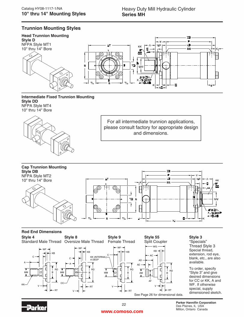
Head Trunnion Mounting Style DNFPA Style MT110" thru 14" Bore
Intermediate Fixed Trunnion Mounting Style DDNFPA Style MT410" thru 14" Bore
Cap Trunnion Mounting Style DBNFPA Style MT210" thru 14" Bore
Catalog HY08-1117-1/NA10" thru 14" Mounting Styles
Trunnion Mounting Styles
Rod End DimensionsStyle 55Split Coupler
Style 8Oversize Male Thread
Style 9Female Thread
Style 3“Specials” Thread Style 3Special thread, extension, rod eye, blank, etc., are also available.
To order, specify “Style 3” and give desired dimensions for CC or KK, A and WF. If otherwise special, supply dimensioned sketch.
Style 4Standard Male Thread
RDB
WF
KBC
MM
V
RT
WF
KB
C
A
MM
CC
V
RT
RDB
WF
KB
C
A
MM
V
RT
KK
KK (INTERNAL)A DEEP
RT
V
RD
AF
AM
AE
AD
AC
KB
WG
BBRD
See Page 26 for dimensional data.
For all intermediate trunnion applications, please consult factory for appropriate design
and dimensions.
www.comoso.com
Parker Hannifin CorporationDes Plaines, IL USAMilton, Ontario Canada
Heavy Duty Mill Hydraulic CylinderSeries MH
23
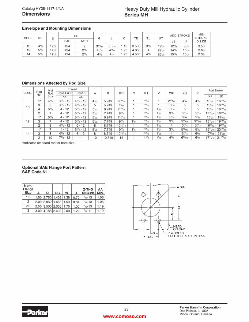
Catalog HY08-1117-1/NADimensions
BOREMMRod Size
10
12
14
41/2
551/2
751/2
787810
31/4 - 1231/2 - 124 - 124 - 124 - 124 - 12
41/2 - 124 - 12
41/2 - 1271/4 - 12
41/4 - 1243/4 - 1251/4 - 1251/2 - 1251/4 - 1251/2 - 126 - 12
51/2 - 126 - 12
—
41/2
551/2
51/2
51/2
51/2
851/2
810
11111
11/4
111/4
11
15/16
15/16
15/16
15/16
15/16
15/16
15/16
15/16
15/16
15/8
5.2495.7496.2497.7496.2497.7498.7497.7498.74910.749
11
11/4
11/4
11/4
11/4
11/2
11/4
11/2
5/16
215/16
33/16
33/16
31/2
33/16
31/2
431/2
441/2
A B RD C RT V WFThread
Style 4 & 9 Style 8 KK CC
133/8
135/8
135/8
1315/16
151/2
1513/16
165/16
1611/16
173/16
1711/16
1611/32
1619/32
1619/32
1629/32
193/32
1913/32
1929/32
2017/32
211/32
2117/32
ZB
Add Stroke
615/16
77/16
715/16
97/8
715/16
97/8
1015/16
97/8
1015/16
14
Dimensions Affected by Rod Size
Optional SAE Flange Port PatternSAE Code 61
XJ
BORE E
125/8
147/8
171/8
#24#24#24
221/2
21/2
311/16
47/16
47/8
311/16
47/16
47/8
1.131.251.25
3.5004.0004.500
31/2
441/2
G J K TD TLEE
SAE NPTF
101214
Envelope and Mounting Dimensions
195/8
227/8
261/8
81/2
101/8
107/8
121/8
141/2
155/8
UTP
ADD STROKE
LB
43/4
5 5
55/16
53/8
511/16
63/16
515/16
67/16
615/16
XG
43/4
55
55/16
53/8
511/16
63/16
57/8
63/8
67/8
Y
Nom.Flange
Size11/2
221/2
3
A1.502.002.503.00
Q2.7503.0623.5004.188
GG1.4061.6882.0002.438
W1.381.531.752.09
X0.700.841.001.22
AA Min.1.061.061.191.19
Z-THDUNC-2B
1/2-131/2-131/2-135/8-11
BD
41/2
51/2
51/2
3.502.632.38
MINSTROKED & DB
W
HEADOR CAP
Z 4 HOLESFULL THREAD DEPTH AA
A DIA.
Q
XGG
RodNo.
1*3421*321*32
*Indicates standard rod for bore size.
www.comoso.com
Parker Hannifin CorporationDes Plaines, IL USAMilton, Ontario Canada
24
Heavy Duty Mill Hydraulic CylinderSeries MH
Clevis Bracket for Knuckle
Order to fit Knuckle.
Knuckle (Female Rod Eye)
Order to fit thread size.
Catalog HY08-1117-1/NAMounting Accessory Dimensions
MR
LR
RE
DD DIA4 HOLES
F
M 25˚
25˚
FL
CB
+ .004+ .002
RE
CL
CD+.001-.002
CD
MR
LR
RE
DD DIA4 HOLES
F
M
FL
CW CWCB
CB
CD
CBCW CW
ER +.004+.002
CD CA
CD
CDKK THREAD
A FULLTHREAD
+ .004+ .002
RE
CD
ER
KK THREAD
+.004+.002CD
A
CE
MR
LR
RE
DD DIA4 HOLES
F
M 25˚
25˚
FL
CB
+ .004+ .002
RE
CL
CD+.001-.002
CD
MR
LR
RE
DD DIA4 HOLES
F
M
FL
CW CWCB
CB
CD
CBCW CW
ER +.004+.002
CD CA
CD
CDKK THREAD
A FULLTHREAD
+ .004+ .002
RE
CD
ER
KK THREAD
+.004+.002CD
A
CE
MR
LR
RE
DD DIA4 HOLES
F
M 25˚
25˚
FL
CB
+ .004+ .002
RE
CL
CD+.001-.002
CD
MR
LR
RE
DD DIA4 HOLES
F
M
FL
CW CWCB
CB
CD
CBCW CW
ER +.004+.002
CD CA
CD
CDKK THREAD
A FULLTHREAD
+ .004+ .002
RE
CD
ER
KK THREAD
+.004+.002CD
A
CE
MR
LR
RE
DD DIA4 HOLES
F
M 25˚
25˚
FL
CB
+ .004+ .002
RE
CL
CD+.001-.002
CD
MR
LR
RE
DD DIA4 HOLES
F
M
FL
CW CWCB
CB
CD
CBCW CW
ER +.004+.002
CD CA
CD
CDKK THREAD
A FULLTHREAD
+ .004+ .002
RE
CD
ER
KK THREAD
+.004+.002CD
A
CE
Female Rod Clevis
Order to fit thread size.
ç
7407769195691956919669196*85361*85361*853616919869198*85362*85363*85363*85364*85365*85365735387353973539
—683686836868369683696837068370683706837168371683726837368373683746837568375735457354773547
74075690896909069091690916909269093690936909469094690956909669097690986909969100735367343773438
74076692056920569206692066920769207692076920869208692096921069210692116921269213735427354273543
74078683686836868369683696837068370683706837168371683726921569215683746837569216735457354582181
51221509405094150942133284509435094413328550945133286509465094750948509495095050951509525095350954
Mating Parts Mating Parts
5/16-247/16-201/2-203/4-163/4-167/8-141-141-14
11/4-1211/4-1211/2-1213/4-1217/8-1221/4-1221/2-1223/4-1231/4-1231/2-124-12
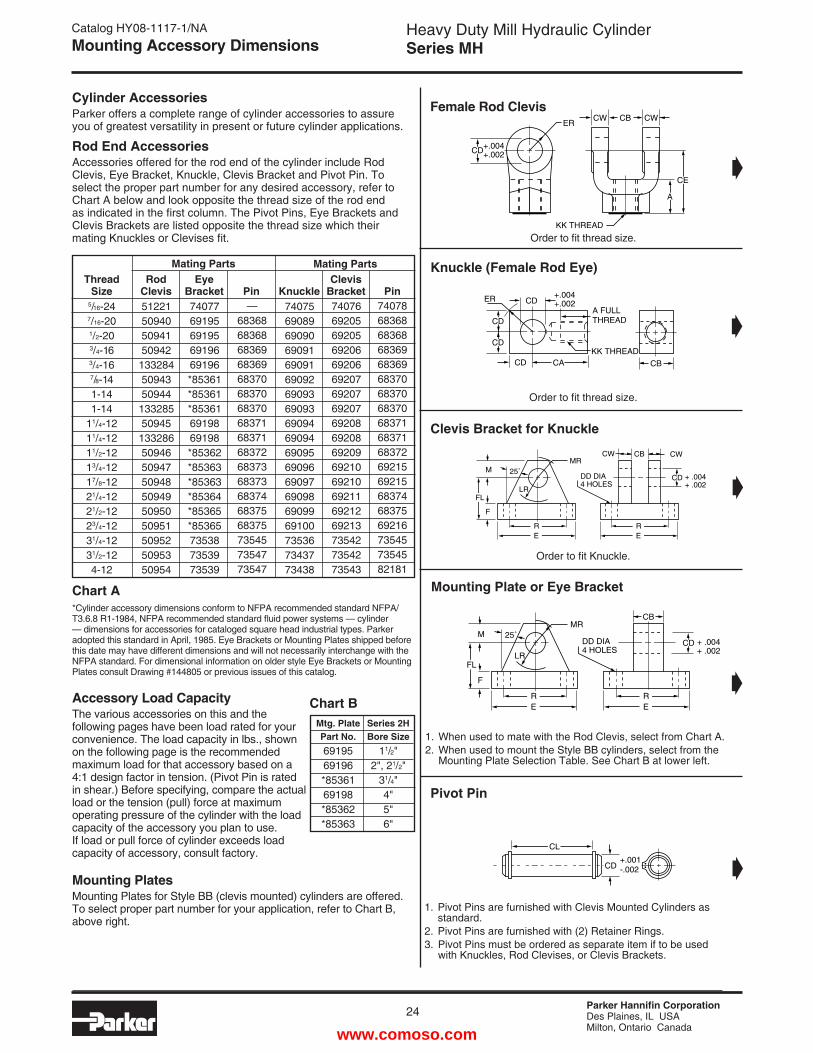
Cylinder AccessoriesParker offers a complete range of cylinder accessories to assure you of greatest versatility in present or future cylinder applications.
Rod End AccessoriesAccessories offered for the rod end of the cylinder include Rod Clevis, Eye Bracket, Knuckle, Clevis Bracket and Pivot Pin. To select the proper part number for any desired accessory, refer to Chart A below and look opposite the thread size of the rod end as indicated in the first column. The Pivot Pins, Eye Brackets and Clevis Brackets are listed opposite the thread size which their mating Knuckles or Clevises fit.
Accessory Load CapacityThe various accessories on this and the following pages have been load rated for your convenience. The load capacity in lbs., shown on the following page is the recommended maximum load for that accessory based on a 4:1 design factor in tension. (Pivot Pin is rated in shear.) Before specifying, compare the actual load or the tension (pull) force at maximum operating pressure of the cylinder with the load capacity of the accessory you plan to use. If load or pull force of cylinder exceeds load capacity of accessory, consult factory.
Mounting PlatesMounting Plates for Style BB (clevis mounted) cylinders are offered. To select proper part number for your application, refer to Chart B, above right.
Series 2HBore Size
11/2"2", 21/2"
31/4"4"5"6"
Chart B
Chart A*Cylinder accessory dimensions conform to NFPA recommended standard NFPA/T3.6.8 R1-1984, NFPA rec om mended standard fluid power systems — cylinder — dimensions for accessories for cataloged square head industrial types. Parker adopted this standard in April, 1985. Eye Brackets or Mounting Plates shipped before this date may have different dimensions and will not necessarily interchange with the NFPA standard. For dimensional information on older style Eye Brackets or Mounting Plates consult Drawing #144805 or previous issues of this catalog.
ç
ç
ç
ç
Pivot Pin
1. Pivot Pins are furnished with Clevis Mounted Cylinders as standard.2. Pivot Pins are furnished with (2) Retainer Rings.3. Pivot Pins must be ordered as separate item if to be used with Knuckles, Rod Clevises, or Clevis Brackets.
Mounting Plate or Eye Bracket
1. When used to mate with the Rod Clevis, select from Chart A.2. When used to mount the Style BB cylinders, select from the Mounting Plate Selection Table. See Chart B at lower left.
Thread Size
Rod Clevis
Eye Bracket
Pin
Knuckle
Clevis Bracket
Pin
Mtg. PlatePart No.6919569196*8536169198*85362*85363
www.comoso.com
Parker Hannifin CorporationDes Plaines, IL USAMilton, Ontario Canada
Heavy Duty Mill Hydraulic CylinderSeries MH
25
Catalog HY08-1117-1/NAMounting Accessory Dimensions
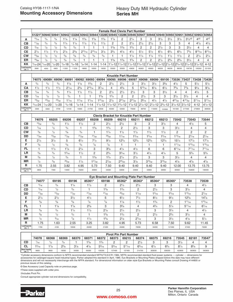
Clevis Bracket for Knuckle Part Number
Female Rod Clevis Part Number
Eye Bracket and Mounting Plate Part Number
ACBCDCECWERKK
CBCDCWDDEF
FLLRM
MRR
51221†
13/16
11/32
5/16
21/413/64
19/64
5/16-242600
509403/43/41/2
11/21/21/2
7/16-204250
509413/43/41/2
11/21/21/2
1/2-204900
13328411/8
11/43/4
23/85/83/4
3/4-1611200
5094315/8
11/2
1215/16
3/4
17/8-14
18800
5094415/8
11/2
1215/16
3/4
11-1419500
5094211/8
11/43/4
21/85/83/4
3/4-1611200
13328515/8
11/2
131/83/4
11-1419500
13328622
13/8
41/8
113/8
11/4-1233500
5094621/4
21/2
13/4
41/2
11/4
13/4
11/2-1245600
5094931/2
321/2
61/2
11/2
21/2
21/4-1298200
5095031/2
33
63/4
11/2
23/4
21/2-1298200
5095131/2
33
63/4
11/2
23/4
23/4-1298200
5095231/2‡†
431/2
73/4
231/2
31/4-12156700
509534‡†
41/2
4813/16
21/4
431/2-12
193200
5094517/8
213/8
33/4
113/8
11/4-1233500
509473
21/2
251/2
11/4
213/4-12
65600
509483
21/2
251/2
11/4
217/8-12
65600
509544‡†
41/2
4813/16
21/4
44-12221200
7407615/32
7/16
3/817/64
21/43/8
15/83/81/2
1.753600
692053/41/21/2
13/32
31/21/2
11/23/41/25/8
2.557300
6920611/43/45/8
17/32
55/8
17/8
13/16
3/429/32
3.8214000
6920711/2
13/4
21/32
61/23/4
21/4
11/2
111/4
4.9519200
692082
13/8
121/32
71/27/8
32
13/8
121/32
5.7336900
6920921/2
13/4
11/429/32
91/27/8
35/8
23/4
13/4
27/32
7.5034000
692113
21/2
11/2
13/16
123/4
141/2
31/2
21/2
31/8
9.4034900
6921021/2
211/2
11/16
123/4
141/4
33/16
21/4
225/32
9.4033000
6921233
11/2
15/16
123/4
16
41/4
3319/32
9.4033800
6921331/2
311/2
15/16
123/4
16
41/4
3319/32
9.4036900
735424
31/2
2113/16
151/2
111/16
611/16
531/2
41/8
12.0083500
7354341/2
42
21/16
171/2
115/16
711/16
53/4
447/8
13.75102600
73544542
21/16
171/2
115/16
711/16
53/4
447/8
13.75108400
740775/16
5/16
17/64
21/43/8
15/83/81/2
1.751700
691953/41/2
13/32
21/23/8
11/83/41/29/16
1.634100
85363*21/2
211/16
71/2
11/2
421/2
227/16
5.7370000
CBCDDDEF
FLLRM
MRR
6919611/43/4
17/32
31/25/8
17/8
11/43/47/8
2.5510500
85361*11/2
121/32
41/27/8
23/8
11/2
111/4
3.2520400
691982
13/821/32
57/8
321/8
13/8
15/8
3.8221200
85362*21/2
13/429/32
61/2
11/8
33/8
21/4
13/4
21/8
4.9549480
*Cylinder accessory dimensions conform to NFPA recommended standard NFPA/T3.6.8 R1-1984, NFPA recommended standard fluid power systems — cylinder — dimensions for accessories for cataloged square head industrial types. Parker adopted this standard in April, 1985. Eye Brackets or Mounting Plates shipped before this date may have different dimensions and will not necessarily interchange with the NFPA standard. For dimensional information on older style Eye Brackets or Mounting Plates consult Drawing #144805 or previous issues of this catalog.O See Accessory Load Capacity note on previous page.•These sizes supplied with cotter pins.†Includes Pivot Pin.Consult appropriate cylinder rod end dimensions for compatibility.
Pivot Pin Part Number
CDCL
85364*3
21/2
13/16
81/2
13/4
43/4
321/2
36.5894200
Knuckle Part Number74075
3/4
11/27/16
7/16
19/32
5/16-243300
690893/4
11/23/41/2
23/32
7/16-205000
7343951/2
91/8
54
511/16
41/2-12308500
7343851/2
91/8
41/2
4511/16
4-12273800
734375
75/8
431/2
4 31/32
31/2-12217300
7353641/2
75/8
431/2
431/32
31/4-12161300
6910035/8
61/2
31/2
341/4
23/4-12123300
6909931/2
61/8
33
41/4
21/2-12110000
6909831/2
513/16
321/2
39/16
21/4-1298700
6909735
21/2
2227/32
17/8-1275000
6909621/4
43/8
21/2
2227/32
13/4-1253500
6909521/4
421/2
13/4
21/2
11/2-1245000
690942
37/16
213/8
131/32
11/4-1233500
6909315/8
213/16
11/2
117/16
1-1421700
6909211/8
23/8
11/2
117/16
7/8-1413000
6909111/8
21/16
11/43/4
11/16
3/4-1612100
690903/4
11/23/41/2
23/32
1/2-205700
ACACBCDERKK
85365*33
15/16
91/2
251/4
31/4
23/4
31/4
7.50121900
735384
31/2
113/16
125/8
111/16
511/16
431/2
41/8
9.6257400
7353941/2
421/16
147/8
115/16
67/16
41/2
451/4
11.4575000
740787/16
15/16
6600
683681/217/88600
683693/425/819300
683701
31/834300
6837113/841/865000
6837213/453/16
105200
683732
53/16
137400
692152
511/16
137400
6837421/263/16
214700
683753
61/4309200
692163
63/4309200
7354531/281/4
420900
73547•
49
565800
821814
85/8565800
Load Capacity Lbs. O
Load Capacity Lbs. O
Load Capacity Lbs. O
Load Capacity Lbs. O
Shear Capacity Lbs. O
www.comoso.com
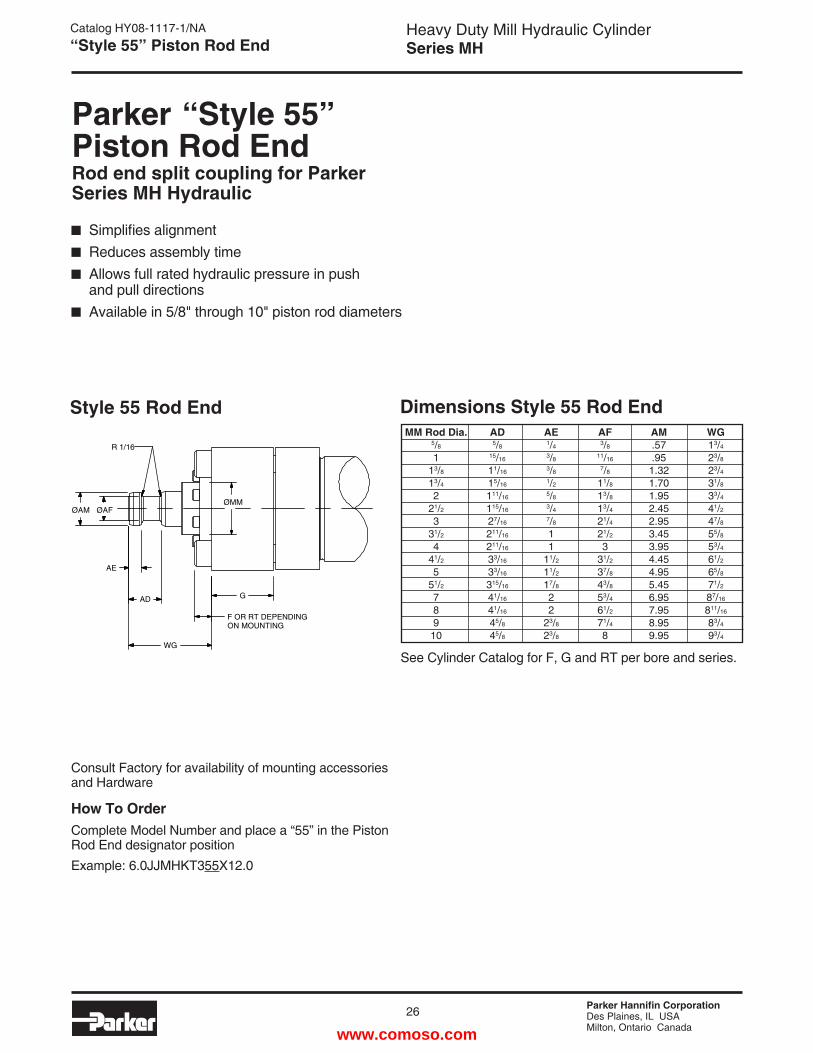
Parker Hannifin CorporationDes Plaines, IL USAMilton, Ontario Canada
26
Heavy Duty Mill Hydraulic CylinderSeries MH
Catalog HY08-1117-1/NA“Style 55” Piston Rod End
Parker “Style 55” Piston Rod EndRod end split coupling for Parker Series MH Hydraulic
Simplifies alignment Reduces assembly time Allows full rated hydraulic pressure in push and pull directions Available in 5/8" through 10" piston rod diameters
Consult Factory for availability of mounting accessories and Hardware
How To OrderComplete Model Number and place a “55” in the Piston Rod End designator positionExample: 6.0JJMHKT355X12.0
Style 55 Rod End Dimensions Style 55 Rod End MM Rod Dia. AD AE AF AM WG 5/8 5/8 1/4 3/8 .57 13/4 1 15/16 3/8 11/16 .95 23/8
13/8 11/16 3/8 7/8 1.32 23/4
13/4 15/16 1/2 11/8 1.70 31/8
2 111/16 5/8 13/8 1.95 33/4
21/2 115/16 3/4 13/4 2.45 41/2
3 27/16 7/8 21/4 2.95 47/8
31/2 211/16 1 21/2 3.45 55/8
4 211/16 1 3 3.95 53/4
41/2 33/16 11/2 31/2 4.45 61/2
5 33/16 11/2 37/8 4.95 65/8
51/2 315/16 17/8 43/8 5.45 71/2
7 41/16 2 53/4 6.95 87/16
8 41/16 2 61/2 7.95 811/16
9 45/8 23/8 71/4 8.95 83/4
10 45/8 23/8 8 9.95 93/4
See Cylinder Catalog for F, G and RT per bore and series.
F OR RT DEPENDING ON MOUNTING
G
WG
AD
AE
ØAFØAM
R 1/16
ØMM
www.comoso.com
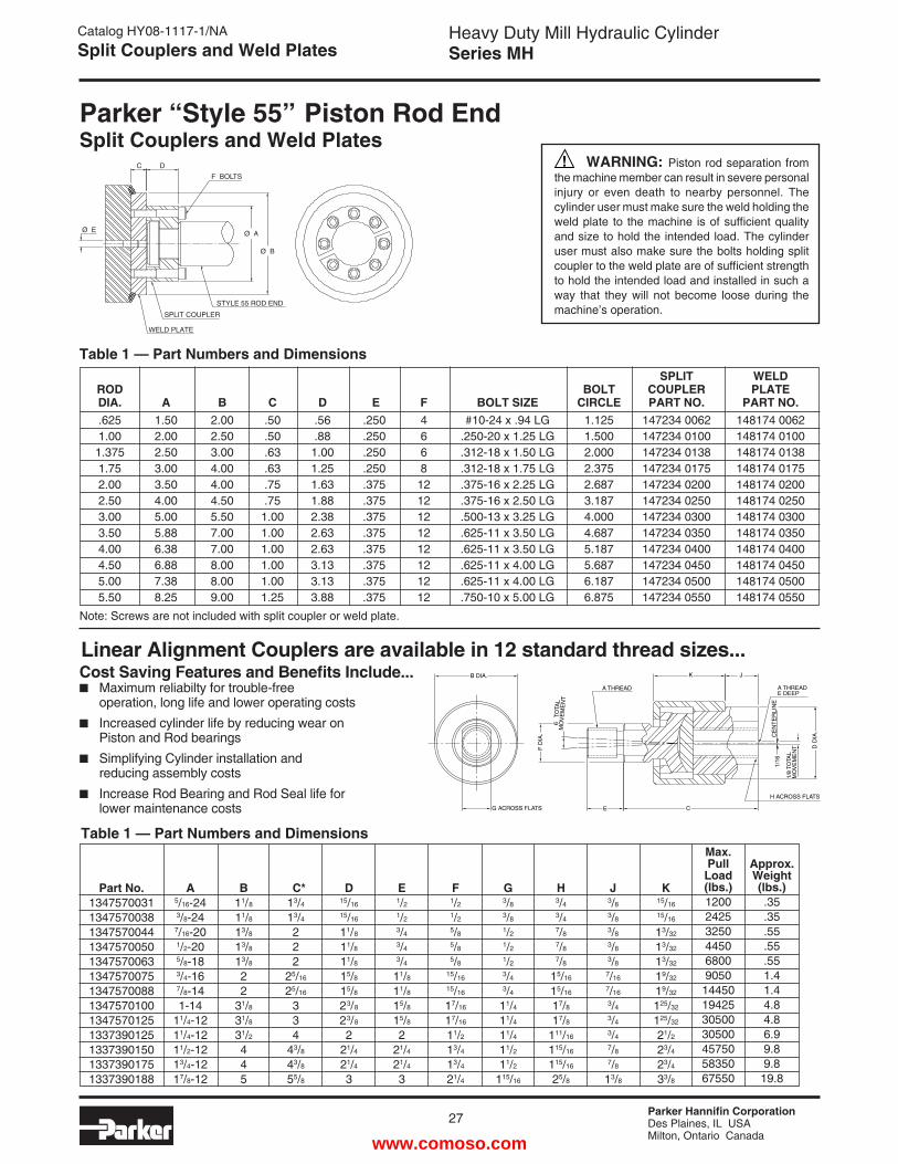
Parker Hannifin CorporationDes Plaines, IL USAMilton, Ontario Canada
Heavy Duty Mill Hydraulic CylinderSeries MH
27
Catalog HY08-1117-1/NASplit Couplers and Weld Plates
Table 1 — Part Numbers and Dimensions
Note: Screws are not included with split coupler or weld plate.
Parker “Style 55” Piston Rod EndSplit Couplers and Weld Plates
WARNING: Piston rod separation from the machine member can result in severe personal injury or even death to nearby personnel. The cylinder user must make sure the weld holding the weld plate to the machine is of sufficient quality and size to hold the intended load. The cylinder user must also make sure the bolts holding split coupler to the weld plate are of sufficient strength to hold the intended load and installed in such a way that they will not become loose during the machine’s operation.
Ø E
C D
F BOLTS
Ø A
Ø B
STYLE 55 ROD END
SPLIT COUPLER
WELD PLATE
SPLIT WELD ROD BOLT COUPLER PLATE DIA. A B C D E F BOLT SIZE CIRCLE PART NO. PART NO. .625 1.50 2.00 .50 .56 .250 4 #10-24 x .94 LG 1.125 147234 0062 148174 0062 1.00 2.00 2.50 .50 .88 .250 6 .250-20 x 1.25 LG 1.500 147234 0100 148174 0100 1.375 2.50 3.00 .63 1.00 .250 6 .312-18 x 1.50 LG 2.000 147234 0138 148174 0138 1.75 3.00 4.00 .63 1.25 .250 8 .312-18 x 1.75 LG 2.375 147234 0175 148174 0175 2.00 3.50 4.00 .75 1.63 .375 12 .375-16 x 2.25 LG 2.687 147234 0200 148174 0200 2.50 4.00 4.50 .75 1.88 .375 12 .375-16 x 2.50 LG 3.187 147234 0250 148174 0250 3.00 5.00 5.50 1.00 2.38 .375 12 .500-13 x 3.25 LG 4.000 147234 0300 148174 0300 3.50 5.88 7.00 1.00 2.63 .375 12 .625-11 x 3.50 LG 4.687 147234 0350 148174 0350 4.00 6.38 7.00 1.00 2.63 .375 12 .625-11 x 3.50 LG 5.187 147234 0400 148174 0400 4.50 6.88 8.00 1.00 3.13 .375 12 .625-11 x 4.00 LG 5.687 147234 0450 148174 0450 5.00 7.38 8.00 1.00 3.13 .375 12 .625-11 x 4.00 LG 6.187 147234 0500 148174 0500 5.50 8.25 9.00 1.25 3.88 .375 12 .750-10 x 5.00 LG 6.875 147234 0550 148174 0550
Cost Saving Features and Benefits Include... Maximum reliabilty for trouble-free operation, long life and lower operating costs Increased cylinder life by reducing wear on Piston and Rod bearings Simplifying Cylinder installation and reducing assembly costs Increase Rod Bearing and Rod Seal life for lower maintenance costs
Linear Alignment Couplers are available in 12 standard thread sizes...
D D
IA.
1/8
TOTA
LM
OV
EM
EN
T
1/16
CE
NT
ER
LIN
E
A THREADE DEEP
JK
CE
F D
IA.
6 T
OTA
LM
OV
EM
EN
T
G ACROSS FLATS
B DIA.
H ACROSS FLATS
A THREAD
Table 1 — Part Numbers and Dimensions
Part No.1347570031134757003813475700441347570050134757006313475700751347570088134757010013475701251337390125133739015013373901751337390188
A5/16-243/8-24
7/16-201/2-205/8-183/4-167/8-141-14
11/4-1211/4-1211/2-1213/4-1217/8-12
B11/8
11/8
13/8
13/8
13/8
22
31/8
31/8
31/2
445
C*13/4
13/4
222
25/16
25/16
334
43/8
43/8
55/8
D15/16
15/16
11/8
11/8
11/8
15/8
15/8
23/8
23/8
221/4
21/4
3
E1/2
1/2
3/4
3/4
3/4
11/8
11/8
15/8
15/8
221/4
21/4
3
F1/2
1/2
5/8
5/8
5/8
15/16
15/16
17/16
17/16
11/2
13/4
13/4
21/4
G3/8
3/8
1/2
1/2
1/2
3/4
3/4
11/4
11/4
11/4
11/2
11/2
115/16
H3/4
3/4
7/8
7/8
7/8
15/16
15/16
17/8
17/8
111/16
115/16
115/16
25/8
J3/8
3/8
3/8
3/8
3/8
7/16
7/16
3/4
3/4
3/4
7/8
7/8
13/8
K15/16
15/16
13/32
13/32
13/32
19/32
19/32
125/32
125/32
21/2
23/4
23/4
33/8
Max.PullLoad(lbs.)12002425325044506800905014450194253050030500457505835067550
Approx.Weight(lbs.).35.35.55.55.551.41.44.84.86.99.89.819.8
www.comoso.com
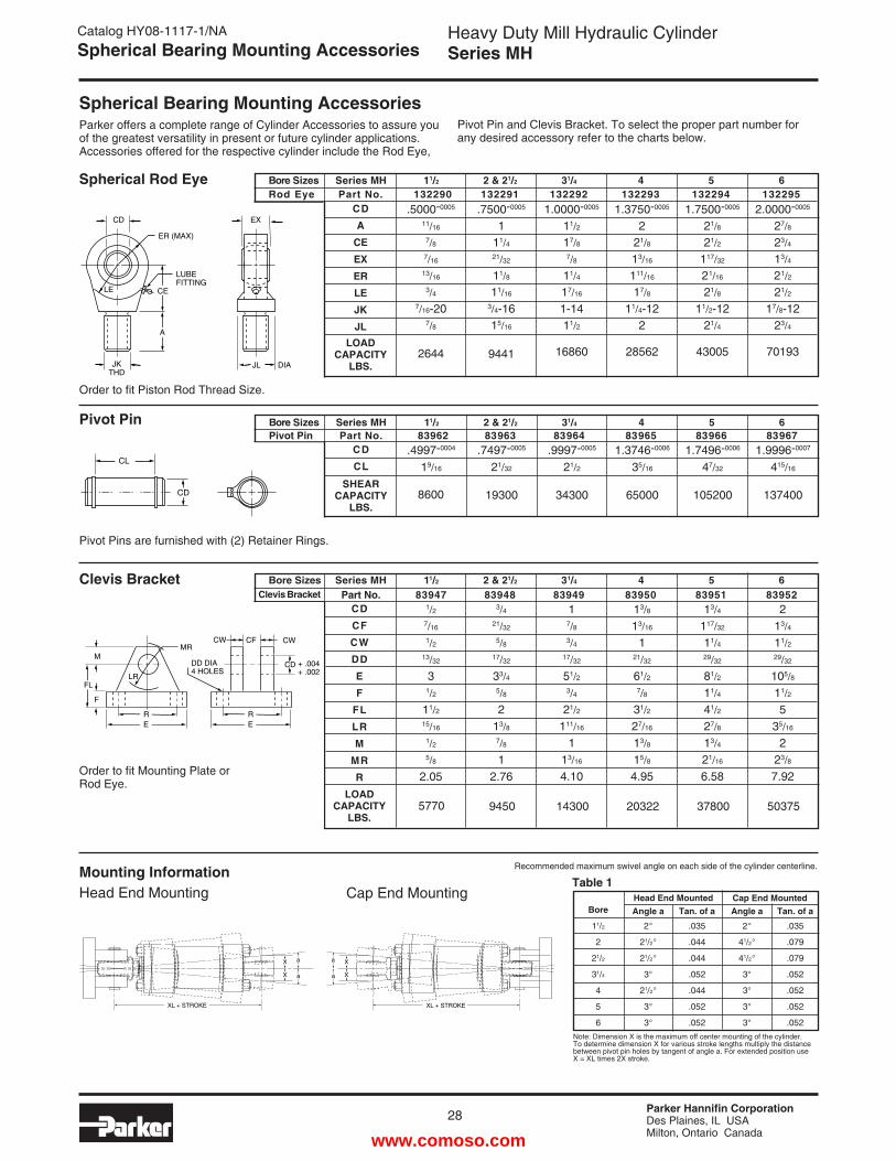
Parker Hannifin CorporationDes Plaines, IL USAMilton, Ontario Canada
28
Heavy Duty Mill Hydraulic CylinderSeries MH
CDCL
SHEARCAPACITY
LBS.
.4997-0004
19/16
.7497-0005
21/32
.9997-0005
21/2
1.3746-0006
35/16
1.7496-0006
47/32
1.9996-0007
415/16
19300 34300 65000 105200 1374008600
Bore Sizes Series MH 11/2 2 & 21/2 31/4 4 5 6Pivot Pin Part No. 83962 83963 83964 83965 83966 83967
Spherical Bearing Mounting Accessories
Catalog HY08-1117-1/NASpherical Bearing Mounting Accessories
Clevis Bracket
Order to fit Mounting Plate or Rod Eye.
Pivot Pin
Pivot Pins are furnished with (2) Retainer Rings.
Parker offers a complete range of Cylinder Accessories to assure you of the greatest versatility in present or future cylinder applications. Accessories offered for the respective cylinder include the Rod Eye,
Pivot Pin and Clevis Bracket. To select the proper part number for any desired accessory refer to the charts below.
CL
CD
Spherical Rod Eye
Order to fit Piston Rod Thread Size.
.5000-0005
11/16
7/87/16
13/16
3/47/16-20
7/8
2644
.7500-0005
111/421/32
11/8
11/16
3/4-16 15/16
9441
1.0000-0005
11/2
17/87/8
11/4
17/16
1-14 11/2
16860
1.3750-0005
221/8
13/16
111/16
17/8
11/4-12 2
28562
1.7500-0005
21/8
21/2
117/32
21/16
21/8
11/2-12 21/4
43005
2.0000-0005
27/8
23/4
13/4
21/2
21/2
17/8-12 23/4
70193
CDA
CEEXERLEJKJL
LOADCAPACITY
LBS.
CDCFCWDDEF
FLLRM
MRR
LOADCAPACITY
LBS.
1/27/16
1/213/32
31/2
11/215/16
1/25/8
2.05
3/421/32
5/817/32
33/45/8
213/87/8
12.76
17/83/4
17/32
51/23/4
21/2
111/16
113/16
4.10
13/8
13/16
121/32
61/27/8
31/2 27/16
13/8
15/8
4.95
13/4
117/32
11/429/32
81/2
11/4
41/2
27/8
13/4
21/16
6.58
213/4
11/229/32
105/8
11/2
535/16
2 23/8
7.92
9450 14300 20322 37800 503755770
Clevis Bracket
MR
LR
RE
DD DIA4 HOLES
F
M
FL
CW CWCF
+ .004+ .002
RE
CD
Bore Sizes Series MH 11/2 2 & 21/2 31/4 4 5 6 Rod Eye Part No. 132290 132291 132292 132293 132294 132295
LE
CD
JKTHD
ER (MAX)
LUBEFITTING
CE
A
EX
JL DIA
Bore Sizes Series MH 11/2 2 & 21/2 31/4 4 5 6 Part No. 83947 83948 83949 83950 83951 83952
XL + STROKE
X
X
a
a
X
X
XL + STROKE
a
a
Mounting InformationHead End Mounting
Recommended maximum swivel angle on each side of the cylinder centerline.
Note: Dimension X is the maximum off center mounting of the cylinder. To determine dimension X for various stroke lengths multiply the distance between pivot pin holes by tangent of angle a. For extended position use X = XL times 2X stroke.
Bore
11/2
2
21/2
31/4
4
5
6
Angle a
2°
21/2°
21/2°
3°
21/2°
3°
3°
Tan. of a
.035
.044
.044
.052
.044
.052
.052
Angle a
2°
41/2°
41/2°
3°
3°
3°
3°
Tan. of a
.035
.079
.079
.052
.052
.052
.052
Head End Mounted Cap End MountedTable 1
Cap End Mounting
www.comoso.com
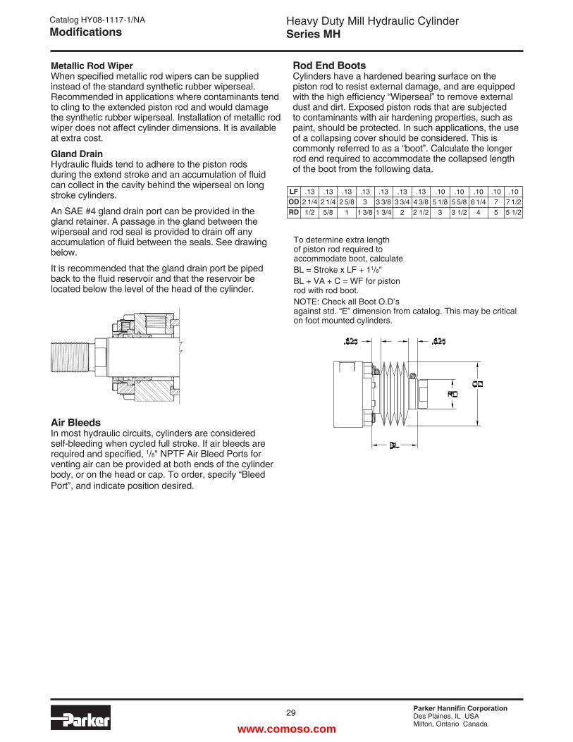
Parker Hannifin CorporationDes Plaines, IL USAMilton, Ontario Canada
Heavy Duty Mill Hydraulic CylinderSeries MH
29
Catalog HY08-1117-1/NAModifications
.1075
Metallic Rod Wiper When specified metallic rod wipers can be supplied instead of the standard synthetic rubber wiperseal. Recommended in applications where contaminants tend to cling to the extended piston rod and would damage the synthetic rubber wiperseal. Installation of metallic rod wiper does not affect cylinder dimensions. It is available at extra cost.
Gland Drain Hydraulic fluids tend to adhere to the piston rods during the extend stroke and an accumulation of fluid can collect in the cavity behind the wiperseal on long stroke cylinders.
An SAE #4 gland drain port can be provided in the gland retainer. A passage in the gland between the wiperseal and rod seal is provided to drain off any accumulation of fluid between the seals. See drawing below.
It is recommended that the gland drain port be piped back to the fluid reservoir and that the reservoir be located below the level of the head of the cylinder.
Air Bleeds In most hydraulic circuits, cylinders are considered self-bleeding when cycled full stroke. If air bleeds are required and specified, 1/8" NPTF Air Bleed Ports for venting air can be provided at both ends of the cylinder body, or on the head or cap. To order, specify “Bleed Port”, and indicate position desired.
Rod End Boots Cylinders have a hardened bearing surface on the piston rod to resist external damage, and are equipped with the high efficiency “Wiperseal” to remove external dust and dirt. Exposed piston rods that are subjected to contaminants with air hardening properties, such as paint, should be protected. In such applications, the use of a collapsing cover should be considered. This is commonly referred to as a “boot”. Calculate the longer rod end required to accommodate the collapsed length of the boot from the following data.
LFODRD
.132 1/41/2
.132 1/45/8
.132 5/8
1
.133
1 3/8
.133 3/81 3/4
.133 3/4
2
.105 1/8
3
.105 5/83 1/2
.106 1/4
4
.107 1/25 1/2
.134 3/82 1/2
To determine extra length of piston rod required to accommodate boot, calculateBL = Stroke x LF + 11/8" BL + VA + C = WF for piston rod with rod boot.NOTE: Check all Boot O.D’s against std. “E” dimension from catalog. This may be critical on foot mounted cylinders.
www.comoso.com
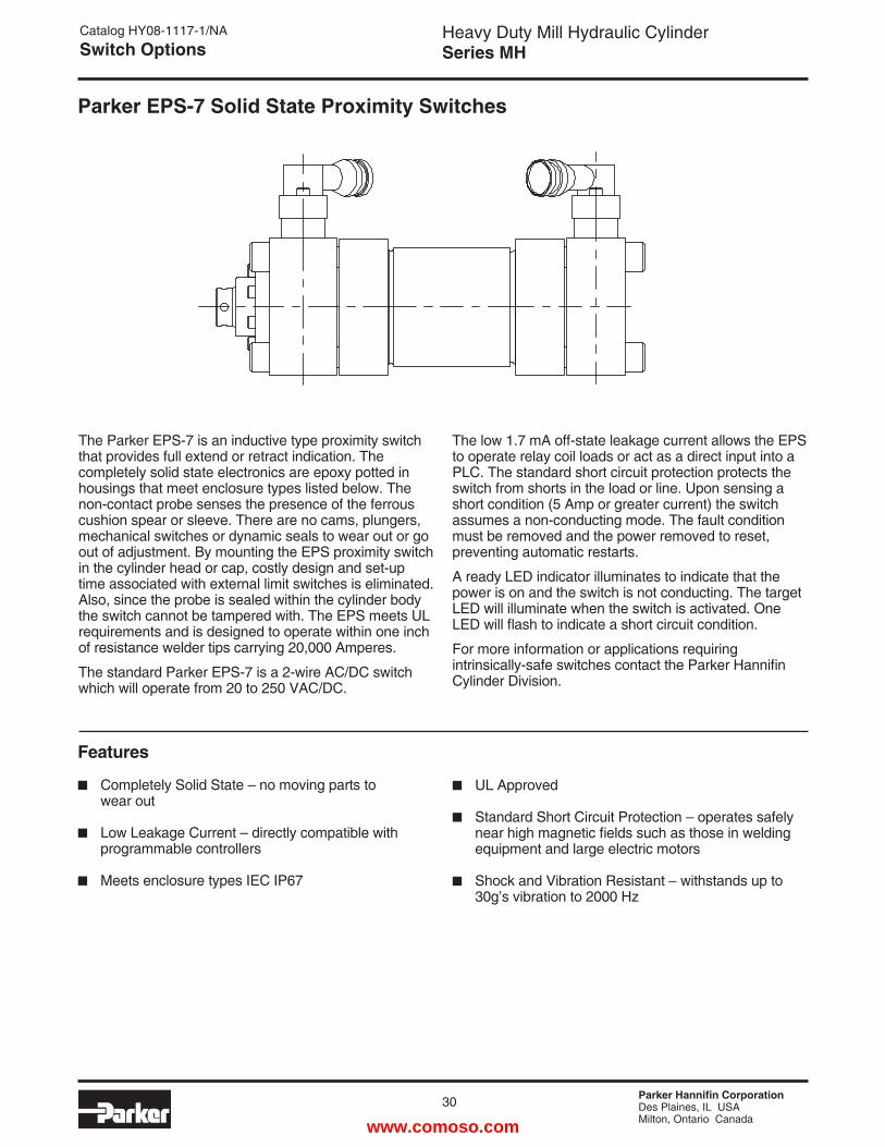
Parker Hannifin CorporationDes Plaines, IL USAMilton, Ontario Canada
30
Heavy Duty Mill Hydraulic CylinderSeries MH
Catalog HY08-1117-1/NASwitch Options
The Parker EPS-7 is an inductive type proximity switch that provides full extend or retract indication. The completely solid state electronics are epoxy potted in housings that meet enclosure types listed below. The non-contact probe senses the presence of the ferrous cushion spear or sleeve. There are no cams, plungers, mechanical switches or dynamic seals to wear out or go out of adjustment. By mounting the EPS proximity switch in the cylinder head or cap, costly design and set-up time associated with external limit switches is eliminated. Also, since the probe is sealed within the cylinder body the switch cannot be tampered with. The EPS meets UL requirements and is designed to operate within one inch of resistance welder tips carrying 20,000 Amperes.
The standard Parker EPS-7 is a 2-wire AC/DC switch which will operate from 20 to 250 VAC/DC.
Parker EPS-7 Solid State Proximity Switches
The low 1.7 mA off-state leakage current allows the EPS to operate relay coil loads or act as a direct input into a PLC. The standard short circuit protection protects the switch from shorts in the load or line. Upon sensing a short condition (5 Amp or greater current) the switch assumes a non-conducting mode. The fault condition must be removed and the power removed to reset, preventing automatic restarts.
A ready LED indicator illuminates to indicate that the power is on and the switch is not conducting. The target LED will illuminate when the switch is activated. One LED will flash to indicate a short circuit condition.
For more information or applications requiring intrinsically-safe switches contact the Parker Hannifin Cylinder Division.
Features
Completely Solid State – no moving parts to wear out
Low Leakage Current – directly compatible with programmable controllers
Meets enclosure types IEC IP67
UL Approved
Standard Short Circuit Protection – operates safely near high magnetic fields such as those in welding equipment and large electric motors
Shock and Vibration Resistant – withstands up to 30g’s vibration to 2000 Hz
www.comoso.com

Parker Hannifin CorporationDes Plaines, IL USAMilton, Ontario Canada
Heavy Duty Mill Hydraulic CylinderSeries MH
31
Catalog HY08-1117-1/NASwitch Options
Load
Green
ACWhite (3)
L2
L1EPS-7
Black (2)Internally Short Circuit Protected 1
1. Green
PinReceptacle
ACColor Code
2. Black3. White
2 3
STANDARD
Cable Length Standard 3' 0853550003
6' 0853550006
9' —
12' 0853550012
Wiring Diagrams and Information ConnectorsThe male quick disconnect on the Parker EPS-7 is a Brad Harrison 40909 connector.Female connects must be purchased with one of the following cable lengths.
Series and Parallel WiringWhen Parker EPS-7 proximity switches are used as inputs to programmable controllers the preferred practice is to connect each switch to a separate input channel of the PC. Series or parallel operations may then be accomplished by the internal PC programming.
Parker EPS-6 or 7 switches may be hard wired for series operation, but the voltage drop through the switches (see specifications) must not drop the available voltage level below what is needed to actuate the load.
Parker EPS-6 or 7 switches may also be hard wired for parallel operation. However, the leakage current of each switch will pass through the load. The total of all leakage currents must not exceed the current required to actuate the load. In most cases, the use of two or more EPS-6 or 7 switches in parallel will require the use of a bypass (shunt) resistor.
Parker Part No.
EPS-7 Heavy Duty Industrial ApplicationsFor top view, see EPS-6.
1.490
HEAD CAP
1
2
3
4
.86" MAX.
1.75" MAX.
www.comoso.com
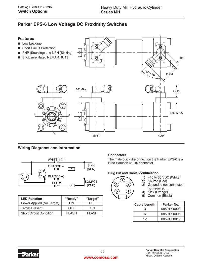
Parker Hannifin CorporationDes Plaines, IL USAMilton, Ontario Canada
32
Heavy Duty Mill Hydraulic CylinderSeries MH
Catalog HY08-1117-1/NASwitch Options
ConnectorsThe male quick disconnect on the Parker EPS-6 is a Brad Harrison 41310 connector.
Wiring Diagrams and Information
Plug Pin and Cable Identification 1) +10 to 30 VDC (White) 2) Source (Red) 3) Grounded not connected nor required 4) Sink (Orange) 5) Common (Black)
LED Function “Ready” “Target” Power Applied (No Target) ON OFF Target Present OFF ON Short Circuit Condition FLASH FLASH
SINK(NPN)
SOURCE(PNP)
WHITE 1 (+)
ORANGE 4
BLACK 5 (-)
RED 2
1
24
5
3
Features Low Leakage Short Circuit Protection PNP (Sourcing) and NPN (Sinking) Enclosure Rated NEMA 4, 6, 13
Cable Length Parker No. 3 085917 0003 6 085917 0006 12 085917 0012
Parker EPS-6 Low Voltage DC Proximity Switches
2.58052˚ MAX
1.490
1.75" MAX.
1
24
3HEAD CAP
.490
.86" MAX.
www.comoso.com
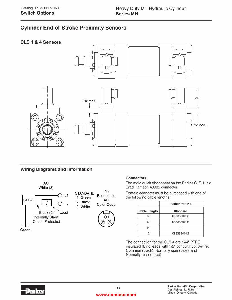
Parker Hannifin CorporationDes Plaines, IL USAMilton, Ontario Canada
Heavy Duty Mill Hydraulic CylinderSeries MH
33
Catalog HY08-1117-1/NASwitch Options
Cylinder End-of-Stroke Proximity Sensors
CLS 1 & 4 Sensors
1
1. Green
PinReceptacle
ACColor Code
2. Black3. White
2 3
STANDARD
Load
Green
ACWhite (3)
L2
L1CLS-1
Black (2)Internally Short Circuit Protected
Cable Length Standard 3' 0853550003
6' 0853550006
9' —
12' 0853550012
Wiring Diagrams and Information
ConnectorsThe male quick disconnect on the Parker CLS-1 is a Brad Harrison 40909 connector.Female connects must be purchased with one of the following cable lengths.
Parker Part No.
The connection for the CLS-4 are 144" PTFE insulated flying leads with 1/2" conduit hub. 3-wire: Common (black), Normally open(blue), and Normally closed (red).
.86" MAX.
1.75" MAX.
2.0
www.comoso.com
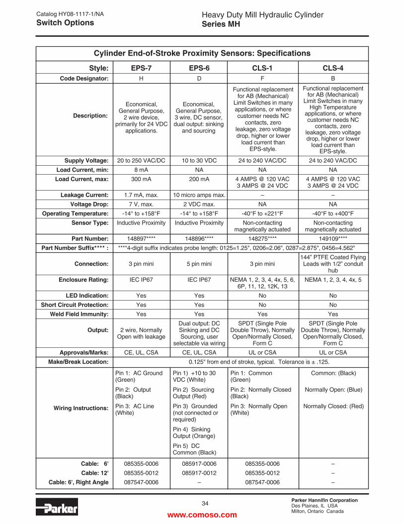
Parker Hannifin CorporationDes Plaines, IL USAMilton, Ontario Canada
34
Heavy Duty Mill Hydraulic CylinderSeries MH
Catalog HY08-1117-1/NASwitch Options
Cylinder End-of-Stroke Proximity Sensors: Specifications
Style: EPS-7 EPS-6 CLS-1 CLS-4 Code Designator: H D F B
Supply Voltage: 20 to 250 VAC/DC 10 to 30 VDC 24 to 240 VAC/DC 24 to 240 VAC/DC Load Current, min: 8 mA NA NA NA Load Current, max: 300 mA 200 mA 4 AMPS @ 120 VAC 4 AMPS @ 120 VAC 3 AMPS @ 24 VDC 3 AMPS @ 24 VDC Leakage Current: 1.7 mA, max. 10 micro amps max. – – Voltage Drop: 7 V, max. 2 VDC max. NA NA Operating Temperature: -14° to +158°F -14° to +158°F -40°F to +221°F -40°F to +400°F Sensor Type: Inductive Proximity Inductive Proximity Non-contacting Non-contacting magnetically actuated magnetically actuated Part Number: 148897**** 148896**** 148275**** 149109**** Part Number Suffix**** : ****4-digit suffix indicates probe length: 0125=1.25", 0206=2.06", 0287=2.875", 0456=4.562" 144” PTFE Coated Flying Connection: 3 pin mini 5 pin mini 3 pin mini Leads with 1/2” conduit hub Enclosure Rating: IEC IP67 IEC IP67 NEMA 1, 2, 3, 4, 4x, 5, 6, NEMA 1, 2, 3, 4, 4x, 5 6P, 11, 12, 12K, 13 LED Indication: Yes Yes No No Short Circuit Protection: Yes Yes No No Weld Field Immunity: Yes Yes Yes Yes Dual output: DC SPDT (Single Pole SPDT (Single Pole Output: 2 wire, Normally Sinking and DC Double Throw), Normally Double Throw), Normally Open with leakage Sourcing, user Open/Normally Closed, Open/Normally Closed, selectable via wiring Form C Form C Approvals/Marks: CE, UL, CSA CE, UL, CSA UL or CSA UL or CSA Make/Break Location:
Wiring Instructions:
Cable: 6' 085355-0006 085917-0006 085355-0006 – Cable: 12' 085355-0012 085917-0012 085355-0012 – Cable: 6', Right Angle 087547-0006 – 087547-0006 –
Functional replacement for AB (Mechanical)
Limit Switches in many High Temperature
applications, or where customer needs NC
contacts, zero leakage, zero voltage drop, higher or lower
load current than EPS-style.
Functional replacement for AB (Mechanical)
Limit Switches in many applications, or where customer needs NC
contacts, zero leakage, zero voltage drop, higher or lower
load current than EPS-style.
Economical, General Purpose, 3 wire, DC sensor, dual output: sinking
and sourcing
Economical, General Purpose,
2 wire device, primarily for 24 VDC
applications.
Description:
0.125" from end of stroke, typical. Tolerance is ± .125.
Pin 1: AC Ground (Green)
Pin 2: Output (Black)
Pin 3: AC Line (White)
Pin 1) +10 to 30 VDC (White)
Pin 2) Sourcing Output (Red)
Pin 3) Grounded (not connected or required)
Pin 4) Sinking Output (Orange)
Pin 5) DC Common (Black)
Pin 1: Common (Green)
Pin 2: Normally Closed (Black)
Pin 3: Normally Open (White)
Common: (Black)
Normally Open: (Blue)
Normally Closed: (Red)
www.comoso.com
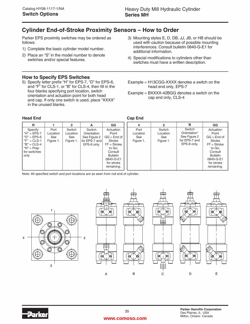
Parker Hannifin CorporationDes Plaines, IL USAMilton, Ontario Canada
Heavy Duty Mill Hydraulic CylinderSeries MH
35
Catalog HY08-1117-1/NASwitch Options
Parker EPS proximity switches may be ordered as follows:1) Complete the basic cylinder model number.2) Place an “S” in the model number to denote
switches and/or special features.
3) Mounting styles E, D, DB, JJ, JB, or HB should be used with caution because of possible mounting interferences. Consult bulletin 0840-G-E1 for additional information.
4) Special modifications to cylinders other than switches must have a written description.
How to Specify EPS Switches5) Specify letter prefix “H” for EPS-7, “D” for EPS-6,
and “F” for CLS-1, or “B” for CLS-4, then fill in the four blanks specifying port location, switch orientation and actuation point for both head and cap. If only one switch is used, place “XXXX” in the unused blanks.
Example = H13CGG-XXXX denotes a switch on the head end only, EPS-7Example = BXXXX-42BGG denotes a switch on the cap end only, CLS-4
Head EndR
Specify:“H” = EPS-7“D” = EPS-6“F” = CLS-1“B” = CLS-4“N” = Prep for switches only
1Port
LocationSee
Figure 1.
3Switch
LocationSee
Figure 1.
ASwitch
OrientationSee Figure 2
for EPS-7 and EPS-6 only.
GGActuation
Point GG = End of
StrokeFF = Stroke
to Go; Consult Bulletin
0840-G-E1 for stroke remaining.
Cap End4
PortLocation
SeeFigure 1.
2Switch
LocationSee
Figure 1.
GGActuation
Point GG = End of
StrokeFF = Stroke
to Go; Consult Bulletin
0840-G-E1 for stroke remaining.
BSwitch
Orientation*See Figure 2
for EPS-7 and EPS-6 only.
Note: All specified switch and port locations are as seen from rod end of cylinder.
Cylinder End-of-Stroke Proximity Sensors – How to Order
1
2
3
4
A B C D E
www.comoso.com
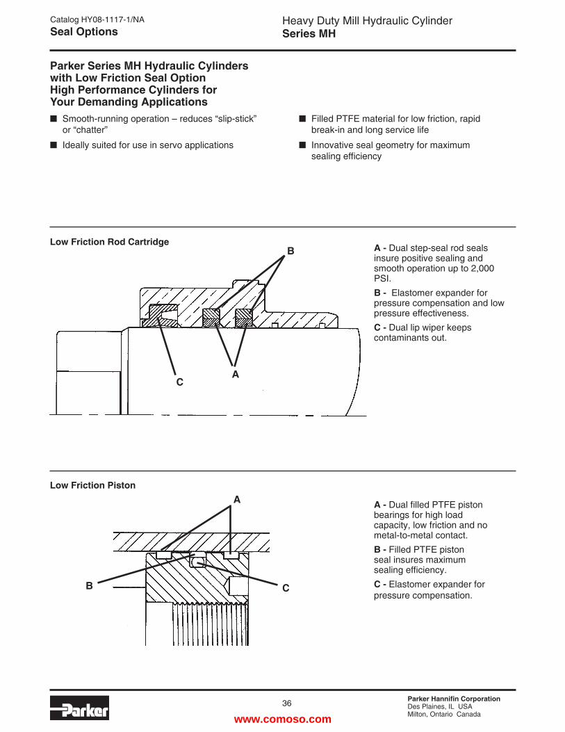
Parker Hannifin CorporationDes Plaines, IL USAMilton, Ontario Canada
36
Heavy Duty Mill Hydraulic CylinderSeries MH
Low Friction Rod Cartridge A - Dual step-seal rod seals insure positive sealing and smooth operation up to 2,000 PSI.B - Elastomer expander for pressure compensation and low pressure effectiveness.C - Dual lip wiper keeps contaminants out.
Low Friction Piston
A - Dual filled PTFE piston bearings for high load capacity, low friction and no metal-to-metal contact.B - Filled PTFE piston seal insures maximum sealing efficiency.C - Elastomer expander for pressure compensation.
Parker Series MH Hydraulic Cylinders with Low Friction Seal Option High Performance Cylinders forYour Demanding Applications Smooth-running operation – reduces “slip-stick” or “chatter”
Ideally suited for use in servo applications
Filled PTFE material for low friction, rapid break-in and long service life
Innovative seal geometry for maximum sealing efficiency
B
AC
C
A
B
Catalog HY08-1117-1/NASeal Options
www.comoso.com
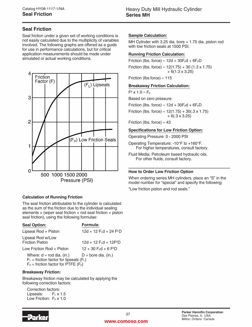
Parker Hannifin CorporationDes Plaines, IL USAMilton, Ontario Canada
Heavy Duty Mill Hydraulic CylinderSeries MH
37
Seal FrictionSeal friction under a given set of working conditions is not easily calculated due to the multiplicity of variables involved. The following graphs are offered as a guide for use in performance calculations, but for critical application measurements should be made under simulated or actual working conditions.
Calculation of Running FrictionThe seal friction attributable to the cylinder is calculated as the sum of the friction due to the individual sealing elements = (wiper seal friction + rod seal friction + piston seal friction), using the following formulae:
Seal Option:Lipseal Rod + Piston 12d + 12 FLd + 24 FLDLipseal Rod w/LowFriction Piston 12d + 12 FLd + 12FpDLow Friction Rod + Piston 12 + 30 Fpd + 6 FpD Where: d = rod dia. (in.) D = bore dia. (in.) FL = friction factor for lipseals (FL) Fp = friction factor for PTFE (Fp)
Breakaway Friction:Breakaway friction may be calculated by applying the following correction factors: Correction factors: Lipseals: FL x 1.5 Low Friction: Fp x 1.0
Sample Calculation:MH Cylinder with 3.25 dia. bore + 1.75 dia. piston rod with low friction seals at 1500 PSI.
Running Friction Calculation:Friction (lbs. force) 12d + 30Fpd + 6FpDFriction (lbs. force) 12(1.75) + 30 (1.3 x 1.75) + 6(1.3 x 3.25)Friction (lbs.force) 115
Breakaway Friction Calculation:Fp x 1.0 Fp
Based on zero pressure:Friction (lbs. force) 12d + 30Fpd + 6FpDFriction (lbs. force) 12(1.75) + 30(.3 x 1.75) + 6(.3 x 3.25)Friction (lbs. force) 43
Specifications for Low Friction Option:Operating Pressure: 0 - 2000 PSI
Operating Temperature: -10°F to +160°F. For higher temperatures, consult factory.Fluid Media: Petroleum based hydraulic oils. For other fluids, consult factory.
How to Order Low Friction Option When ordering series MH cylinders, place an “S” in the model number for “special” and specify the following:“Low friction piston and rod seals.”
Formula:
Catalog HY08-1117-1/NASeal Friction
www.comoso.com
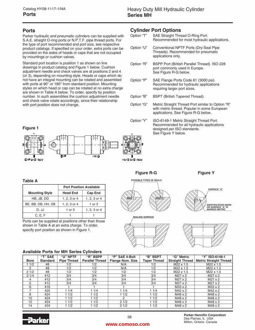
Parker Hannifin CorporationDes Plaines, IL USAMilton, Ontario Canada
38
Heavy Duty Mill Hydraulic CylinderSeries MH
Catalog HY08-1117-1/NAPorts
PortsParker hydraulic and pneumatic cylinders can be supplied with S.A.E. straight O-ring ports or N.P.T.F. pipe thread ports. For the type of port recommended and port size, see respective product catalogs. If specified on your order, extra ports can be provided on the sides of heads or caps that are not occupied by mountings or cushion valves.
Standard port location is position 1 as shown on line drawings in product catalog and Figure 1 below. Cushion adjustment needle and check valves are at positions 2 and 4 (or 3), depending on mounting style. Heads or caps which do not have an integral mounting can be rotated and assembled with ports at 90° or 180° from standard position. Mounting styles on which head or cap can be rotated at no extra charge are shown in Table A below. To order, specify by position number. In such assemblies the cushion adjustment needle and check valve rotate accordingly, since their relationship with port position does not change.
Port Position Available
Mounting Style Head End Cap End
HB, JB, DD 1, 2, 3 or 4 1, 2, 3 or 4
BE, BB, DB, HH, SB 1, 2, 3 or 4 1 or 3
D, JJ 1 or 3 1, 2, 3 or 4
C, E, F 1 1
Ports can be supplied at positions other than those shown in Table A at an extra charge. To order, specify port position as shown in Figure 1.
Cylinder Port OptionsOption “T” SAE Straight Thread O-Ring Port. Recommended for most hydraulic applications.
Option “U” Conventional NPTF Ports (Dry-Seal Pipe Threads). Recommended for pneumatic applications only.
Option “R” BSPP Port (British Parallel Thread). ISO 228 port commonly used in Europe. See Figure R-G below.
Option “P” SAE Flange Ports Code 61 (3000 psi). Recommended for hydraulic applications requiring larger port sizes.
Option “B” BSPT (British Tapered Thread).
Option “G” Metric Straight Thread Port similar to Option “R” with metric thread. Popular in some European applications. See Figure R-G below.
Option “Y” ISO-6149-1 Metric Straight Thread Port. Recommended for all hydraulic applications designed per ISO standards. See Figure Y below.
Available Ports for MH Series Cylinders
Table A
Bore1 1/2
22 1/23 1/4
45678101214
“G” MetricStraight Thread
M22 x 1.5M22 x 1.5M22 x 1.5M27 x 2M27 x 2M27 x 2M33 x 2M42 x 2M48 x 2M48 x 2M48 x 2M48 x 2
“Y” ISO-6149-1Metric Straight Thread
M22 x 1.5M22 x 1.5M22 x 1.5M27 x 2M27 x 2M27 x 2M33 x 2M42 x 2M48 x 2M48 x 2M48 x 2M48 x 2
“B” BSPTTaper Thread
1/21/21/23/43/43/41
1 1/41 1/21 1/21 1/21 1/2
“P” SAE 4-BoltFlange Nom. Size
N/AN/A1/23/43/43/41
1 1/41 1/2
22 1/22 1/2
“U” NPTFPipe Thread
1/21/21/23/43/43/41
1 1/41 1/21 1/21 1/21 1/2
“R” BSPPParallel Thread
1/21/21/23/43/43/41
1 1/41 1/21 1/21 1/21 1/2
“T” SAEStandard
#8#8#8#12#12#12#16#20#24#24#24#24
Figure 1
POSSIBLE TYPES OF SEALS
SEALING SURFACE
SURFACE “A”
IDENTIFICATION MARK OR SURFACE “A” ISMARKED METRIC
Figure R-G Figure YPOSSIBLE TYPES OF SEALS
SEALING SURFACE
SURFACE “A”
IDENTIFICATION MARK OR SURFACE “A” ISMARKED METRIC
www.comoso.com
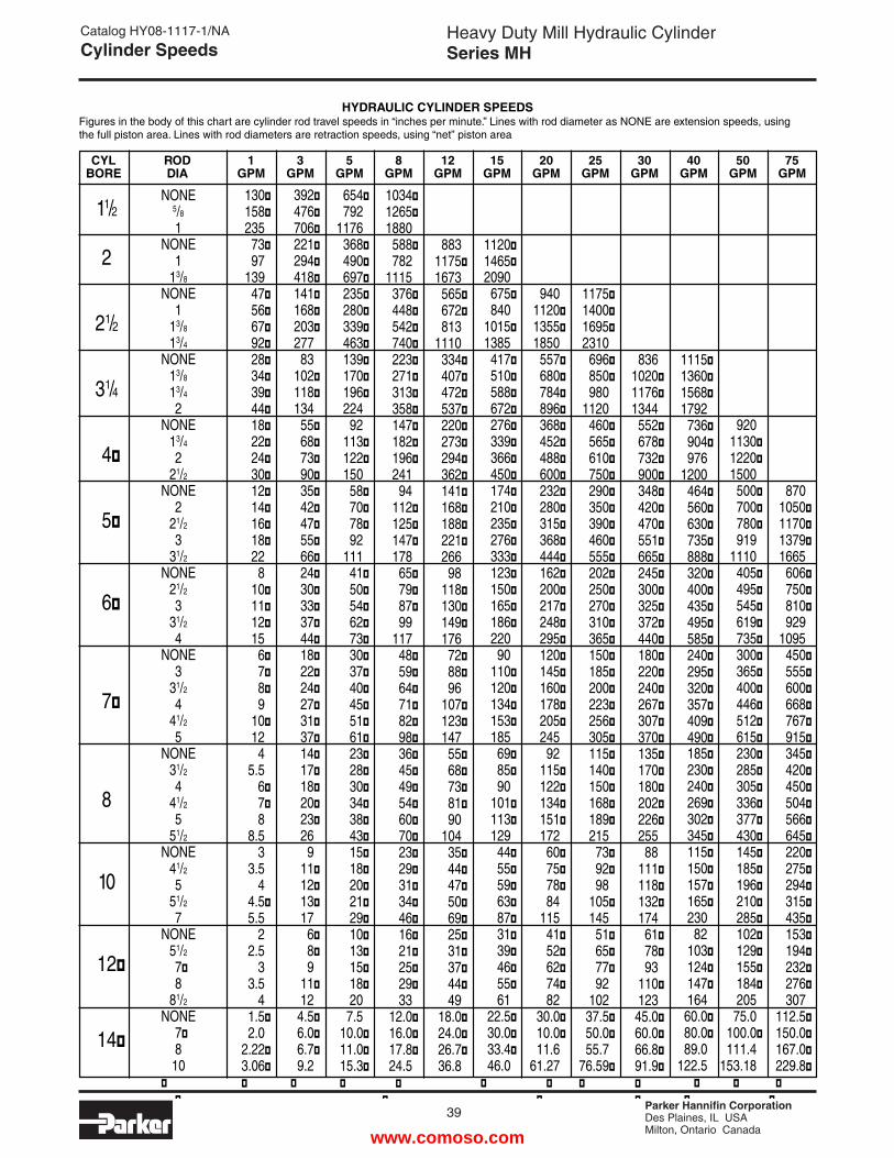
Parker Hannifin CorporationDes Plaines, IL USAMilton, Ontario Canada
Heavy Duty Mill Hydraulic CylinderSeries MH
39
Catalog HY08-1117-1/NACylinder Speeds
CYL ROD 1 3 5 8 12 15 20 25 30 40 50 75BORE DIA GPM GPM GPM GPM GPM GPM GPM GPM GPM GPM GPM GPM
HYDRAULIC CYLINDER SPEEDSFigures in the body of this chart are cylinder rod travel speeds in “inches per minute.” Lines with rod diameter as NONE are extension speeds, usingthe full piston area. Lines with rod diameters are retraction speeds, using “net” piston area
392�476�706�221�294�418�141�168�203�27783
102�118�13455�68�73�90�35�42�47�55�66�24�30�33�37�44�18�22�24�27�31�37�14�17�18�20�23�26
911�12�13�17
6�8�9
11�124.5�6.0�6.7�9.2
�
654�792
1176368�490�697�235�280�339�463�139�170�196�22492
113�122�15058�70�78�92
11141�50�54�62�73�30�37�40�45�51�61�23�28�30�34�38�43�15�18�20�21�29�10�13�15�18�207.5
10.0�11.0�15.3��
��
�
1034�1265�1880
588�782
1115376�448�542�740�223�271�313�358�147�182�196�24194
112�125�147�17865�79�87�99
11748�59�64�71�82�98�36�45�49�54�60�70�23�29�31�34�46�16�21�25�29�33
12.0�16.0�17.8�24.5�
�
�
��
8831175�1673
565�672�813
1110334�407�472�537�220�273�294�362�141�168�188�221�26698
118�130�149�17672�88�96
107�123�14755�68�73�81�90
10435�44�47�50�69�25�31�37�44�49
18.0�24.0�26.7�36.8
��
1120�1465�2090
675�840
1015�1385
417�510�588�672�276�339�366�450�174�210�235�276�333�123�150�165�186�22090
110�120�134�153�18569�85�90
101�113�12944�55�59�63�87�31�39�46�55�61
22.5�30.0�33.4�46.0
�
��
�
9401120�1355�1850
557�680�784�896�368�452�488�600�232�280�315�368�444�162�200�217�248�295�120�145�160�178�205�24592
115�122�134�151�17260�75�78�84
11541�52�62�74�82
30.0�10.0�11.6
61.27�
��
1175�1400�1695�2310
696�850�980
1120460�565�610�750�290�350�390�460�555�202�250�270�310�365�150�185�200�223�256�305�115�140�150�168�189�21573�92�98
105�14551�65�77�92
10237.5�50.0�55.7
76.59��
��
�
8361020�1176�1344
552�678�732�900�348�420�470�551�665�245�300�325�372�440�180�220�240�267�307�370�135�170�180�202�226�25588
111�118�132�17461�78�93
110�12345.0�60.0�66.8�91.9���
1115�1360�1568�1792
736�904�976
1200464�560�630�735�888�320�400�435�495�585�240�295�320�357�409�490�185�230�240�269�302�345�115�150�157�165�23082
103�124�147�16460.0�80.0�89.0
122.5�
�
9201130�1220�1500
500�700�780�919
1110405�495�545�619�735�300�365�400�446�512�615�230�285�305�336�377�430�145�185�196�210�285�102�129�155�184�20575.0
100.0�111.4
153.18�
��
�
8701050�1170�1379�1665
606�750�810�929
1095450�555�600�668�767�915�345�420�450�504�566�645�220�275�294�315�435�153�194�232�276�307
112.5�150.0�167.0�229.8��
��
��
�
130�158�23573�97
13947�56�67�92�28�34�39�44�18�22�24�30�12�14�16�18�22
810�11�12�15
6�7�8�9
10�12
45.5
6�7�8
8.53
3.54
4.5�5.5
22.5
33.5
41.5�2.0
2.22�3.06��
NONE5/8
1NONE
113/8
NONE1
13/8
13/4
NONE13/8
13/4
2NONE
13/4
221/2
NONE2
21/2
331/2
NONE21/2
331/2
4NONE
331/2
441/2
5NONE
31/2
441/2
551/2
NONE41/2
551/2
7NONE
51/2
7�8
81/2
NONE7�810
��
��
��
��
11/2
2
21/2
31/4
4�
5�
6�
7�
8
10
12�
14�
�www.comoso.com
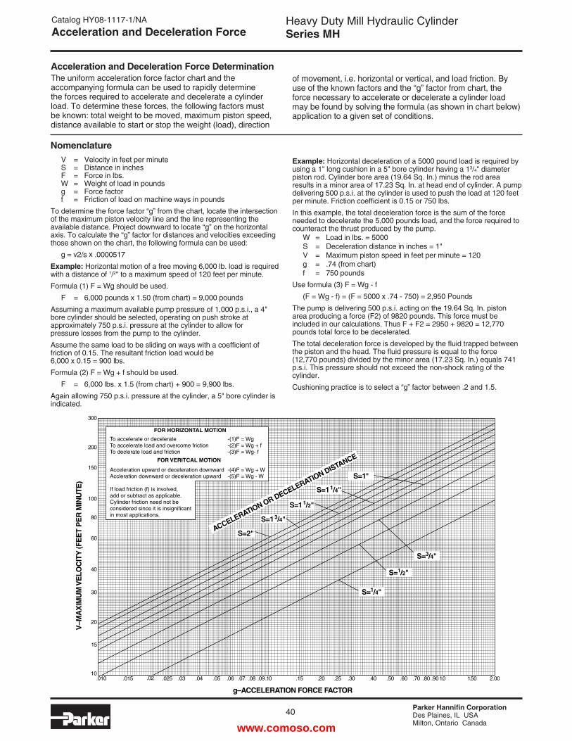
Parker Hannifin CorporationDes Plaines, IL USAMilton, Ontario Canada
40
Heavy Duty Mill Hydraulic CylinderSeries MH
Catalog HY08-1117-1/NAAcceleration and Deceleration Force
300
200
150
100
80
60
40
30
20
15
10.010 .015 .02 .025 .03 .04 .05 .06 .07 .08 .09.10 .15 .20 .25 .30 .40 .50 .60 .70 .80 .901.0 1.50 2.00
g–ACCELERATION FORCE FACTOR
V–M
AX
IMU
M V
ELO
CIT
Y (F
EE
T P
ER
MIN
UTE
)
ACCELERATION OR DECELERATION DISTANCE
S=2"
S=1 3/4"
S=1 1/2"
S=1 1/4"
S=1"
S=1/4"
S=1/2"
S=3/4"
FOR HORIZONTAL MOTION
To accelerate or decelerate -(1)F = WgTo accelerate load and overcome friction -(2)F = Wg + fTo declerate load and friction -(3)F = Wg- f
FOR VERITCAL MOTION
Acceleration upward or deceleration downward -(4)F = Wg + WAccleration downward or deceleration upward -(5)F = Wg - W
If load friction (f) is involved,add or subtract as applicable. Cylinder friction need not be considered since it is insignificantin most applications.
Acceleration and Deceleration Force DeterminationThe uniform acceleration force factor chart and the accompanying formula can be used to rapidly determine the forces required to accelerate and decelerate a cylinder load. To determine these forces, the following factors must be known: total weight to be moved, maximum piston speed, distance available to start or stop the weight (load), direction
of movement, i.e. horizontal or vertical, and load friction. By use of the known factors and the “g” factor from chart, the force necessary to accelerate or decelerate a cylinder load may be found by solving the formula (as shown in chart below) application to a given set of conditions.
Nomenclature V = Velocity in feet per minute S = Distance in inches F = Force in lbs. W = Weight of load in pounds g = Force factor f = Friction of load on machine ways in poundsTo determine the force factor “g” from the chart, locate the intersection of the maximum piston velocity line and the line representing the available distance. Project downward to locate “g” on the horizontal axis. To calculate the “g” factor for distances and velocities exceeding those shown on the chart, the following formula can be used: g = v2/s x .0000517Example: Horizontal motion of a free moving 6,000 lb. load is required with a distance of 1/2" to a maximum speed of 120 feet per minute.Formula (1) F = Wg should be used. F = 6,000 pounds x 1.50 (from chart) = 9,000 poundsAssuming a maximum available pump pressure of 1,000 p.s.i., a 4" bore cylinder should be selected, operating on push stroke at approximately 750 p.s.i. pressure at the cylinder to allow for pressure losses from the pump to the cylinder.Assume the same load to be sliding on ways with a coefficient of friction of 0.15. The resultant friction load would be 6,000 x 0.15 = 900 lbs.Formula (2) F = Wg + f should be used. F = 6,000 lbs. x 1.5 (from chart) + 900 = 9,900 lbs.Again allowing 750 p.s.i. pressure at the cylinder, a 5" bore cylinder is indicated.
Example: Horizontal deceleration of a 5000 pound load is required by using a 1" long cushion in a 5" bore cylinder having a 13/4" diameter piston rod. Cylinder bore area (19.64 Sq. In.) minus the rod area results in a minor area of 17.23 Sq. In. at head end of cylinder. A pump delivering 500 p.s.i. at the cylinder is used to push the load at 120 feet per minute. Friction coefficient is 0.15 or 750 lbs.In this example, the total deceleration force is the sum of the force needed to decelerate the 5,000 pounds load, and the force required to counteract the thrust produced by the pump. W = Load in lbs. = 5000 S = Deceleration distance in inches = 1" V = Maximum piston speed in feet per minute = 120 g = .74 (from chart) f = 750 poundsUse formula (3) F = Wg - f (F = Wg - f) = (F = 5000 x .74 - 750) = 2,950 PoundsThe pump is delivering 500 p.s.i. acting on the 19.64 Sq. In. piston area producing a force (F2) of 9820 pounds. This force must be included in our calculations. Thus F + F2 = 2950 + 9820 = 12,770 pounds total force to be decelerated.The total deceleration force is developed by the fluid trapped between the piston and the head. The fluid pressure is equal to the force (12,770 pounds) divided by the minor area (17.23 Sq. In.) equals 741 p.s.i. This pressure should not exceed the non-shock rating of the cylinder.Cushioning practice is to select a “g” factor between .2 and 1.5.
www.comoso.com
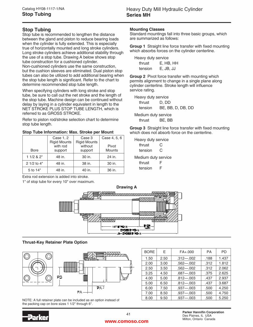
Parker Hannifin CorporationDes Plaines, IL USAMilton, Ontario Canada
Heavy Duty Mill Hydraulic CylinderSeries MH
41
Stop Tubing Stop tube is recommended to lengthen the distance between the gland and piston to reduce bearing loads when the cylinder is fully extended. This is especially true of horizontally mounted and long stroke cylinders. Long stroke cylinders achieve additional stability through the use of a stop tube. Drawing A below shows stop tube construction for a cushioned cylinder. Non-cushioned cylinders use the same construction, but the cushion sleeves are eliminated. Dual piston stop tubes can also be utilized to add additional bearing when the stop tube length is significant. Refer to the chart to determine recommended stop tube length.When specifying cylinders with long stroke and stop tube, be sure to call out the net stroke and the length of the stop tube. Machine design can be continued without delay by laying in a cylinder equivalent in length to the NET STROKE PLUS STOP TUBE LENGTH, which is referred to as GROSS STROKE.Refer to piston rod/stroke selection chart to determine stop tube length.
Mounting Classes Standard mountings fall into three basic groups, which are summarized as follows:
Group 1 Straight line force transfer with fixed mounting which absorbs forces on the cylinder centerline.
Heavy duty service thrust E, HB, HH tension E, JB, JJ
Group 2 Pivot force transfer with mounting which permits alignment to change in a single plane along cylinder centerline. Stroke length will influence service rating.
Heavy duty service thrust D, DD tension BE, BB, D, DB, DD
Medium duty service thrust BE, BB
Group 3 Straight line force transfer with fixed mounting which does not absorb force on the centerline.
Heavy duty service thrust C tension C
Medium duty service thrust F tension F
Catalog HY08-1117-1/NAStop Tubing
Drawing A
BORE E FA+.000 PA PD
1.502.002.503.254.005.006.007.008.00
2.503.003.504.505.006.507.508.509.50
.312—.002
.562—.002
.562—.002
.687—.003
.812—.003
.812—.003
.937—.003
.937—.003
.937—.003
.188
.312
.312
.375
.437
.437
.500
.500
.500
1.4371.8122.0622.6252.9373.6874.2504.7505.250NOTE: A full retainer plate can be included as an option instead of
the packing cap on bore sizes 1 1/2" through 6".
Thrust-Key Retainer Plate Option
Stop Tube Information: Max. Stroke per Mount Case 1, 2 Case 3 Case 4, 5, 6 Rigid Mounts Rigid Mounts with rod without Pivot Bore support support Mounts
1 1/2 & 2" 48 in. 30 in. 24 in.
2 1/2 to 4" 48 in. 38 in. 30 in.
5 to 14" 48 in. 40 in. 36 in.
Extra rod extension is added into stroke.1" of stop tube for every 10" over maximum.
www.comoso.com
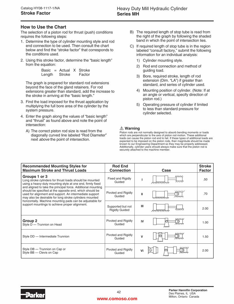
Parker Hannifin CorporationDes Plaines, IL USAMilton, Ontario Canada
42
Heavy Duty Mill Hydraulic CylinderSeries MH
Catalog HY08-1117-1/NAStroke Factor
Recommended Mounting Styles for Rod End StrokeMaximum Stroke and Thrust Loads Connection Case Factor
How to Use the ChartThe selection of a piston rod for thrust (push) conditions requires the following steps:1. Determine the type of cylinder mounting style and rod
end connection to be used. Then consult the chart below and find the “stroke factor” that corresponds to the conditions used.
2. Using this stroke factor, determine the “basic length” from the equation:
The graph is prepared for standard rod extensions beyond the face of the gland retainers. For rod extensions greater than standard, add the increase to the stroke in arriving at the “basic length.”
3. Find the load imposed for the thrust application by multiplying the full bore area of the cylinder by the system pressure.
4. Enter the graph along the values of “basic length” and “thrust” as found above and note the point of intersection:
A) The correct piston rod size is read from the diagonally curved line labeled “Rod Diameter” next above the point of intersection.
B) The required length of stop tube is read from the right of the graph by following the shaded band in which the point of intersection lies.
C) If required length of stop tube is in the region labeled “consult factory,” submit the following information for an individual analysis:
1) Cylinder mounting style. 2) Rod end connection and method of guiding load. 3) Bore, required stroke, length of rod extension (Dim. “LA”) if greater than standard, and series of cylinder used. 4) Mounting position of cylinder. (Note: If at an angle or vertical, specify direction of piston rod.) 5) Operating pressure of cylinder if limited to less than standard pressure for cylinder selected.
WarningPiston rods are not normally designed to absorb bending moments or loads which are perpendicular to the axis of piston rod motion. These additional loads can cause the piston rod end to fail. If these types of additional loads are expected to be imposed on the piston rods, their magnitude should be made known to our Engineering Department so they may be properly addressed. Additionally, cylinder users should always make sure that the piston rod is securely attached to the machine member.
Groups 1 or 3Long stroke cylinders for thrust loads should be mounted using a heavy-duty mounting style at one end, firmly fixed and aligned to take the principal force. Additional mounting should be specified at the opposite end, which should be used for alignment and support. An intermediate support may also be desirable for long stroke cylinders mounted horizontally. Machine mounting pads can be adjustable for support mountings to achieve proper alignment.
Group 2Style D — Trunnion on Head
Style DD — Intermediate Trunnion
Style DB — Trunnion on Cap orStyle BB — Clevis on Cap
Fixed and RigidlyGuided
Pivoted and RigidlyGuided
Supported but not Rigidly Guided
Pivoted and RigidlyGuided
Pivoted and RigidlyGuided
Pivoted and Rigidly Guided
.50
.70
2.00
1.00
1.50
2.00
I
II
III
IV
V
VI
Basic = Actual X Stroke Length Stroke Factor
www.comoso.com
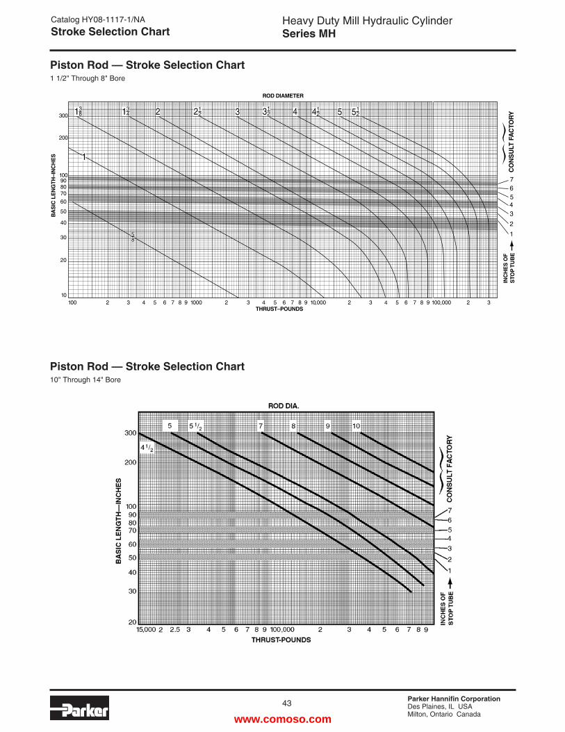
Parker Hannifin CorporationDes Plaines, IL USAMilton, Ontario Canada
Heavy Duty Mill Hydraulic CylinderSeries MH
43
Catalog HY08-1117-1/NAStroke Selection Chart
Piston Rod — Stroke Selection Chart1 1/2" Through 8" Bore
Piston Rod — Stroke Selection Chart10" Through 14" Bore
100 2 3 4 5 6 7 8 9 1000 2 3 4 5 6 7 8 9 10,000 2 3 4 5 6 7 8 9 100,000 2 310
20
30
40
50
60
300
200
100908070
THRUST–POUNDS
ROD DIAMETER
BA
SIC
LE
NG
TH–I
NC
HE
S
INC
HE
S O
F
STO
P T
UB
E
1
2
34567
CO
NS
ULT
FA
CTO
RY
58
1
134 2 21
2 3 312 4 41
2 5 512
381
www.comoso.com
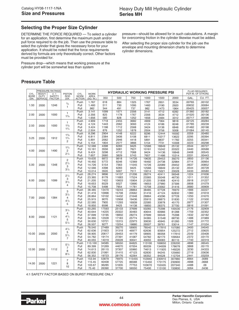
Parker Hannifin CorporationDes Plaines, IL USAMilton, Ontario Canada
44
Heavy Duty Mill Hydraulic CylinderSeries MH
Selecting the Proper Size Cylinder
Pressure Table
4:1 SAFETY FACTOR BASED ON BURST PRESSURE ONLY
PushPullPull
PushPullPull
PushPullPullPull
PushPullPullPull
PushPullPullPull
PushPullPullPullPull
PushPullPullPullPull
PushPullPullPullPullPull
PushPullPullPullPullPull
PushPullPullPullPull
PushPullPullPullPull
PushPullPullPull
1.7671.460.9823.1412.3561.6564.9094.1243.4242.5048.2966.8115.8915.15412.56610.1619.4247.65719.63516.49214.72612.56610.01428.27423.36521.20518.65315.70838.48531.41628.86425.91522.58518.85050.26540.64437.69934.36530.63026.50778.54062.63658.90554.78240.055113.10089.39974.61362.83056.352153.94115.45103.6775.40
CYL.WORK
ACTION
WORKAREA
(SQ. IN.)
PISTON ROD DIA.
4 : 1 SAFETY FACTOR
HEAVY DUTY
SERVICE
CYL.BOREDIA.
1.50
2.00
2.50
3.25
4.00
5.00
6.00
7.00
8.00
10.00
12.00
14.00
1246
1000
1000
1912
1490
1348
1099
1384
1121
2000
1112
1221
PRESSURE RATINGS
350618511344
1099825580
171814431198876
290423842062180443983556329826806872577251544398350598968178742265295498
134701099610102907079056598
17593142251319512028107219277
2748921923206171917414019345853126926115219911972353879404083628526390
884730491
15711178828
24552062171212524148340629462577628350814712382998188246736362835007
14137116831060393277854
19243157081443212958112939425
2513320322188501718315315132543927031318294532739120028565504467037307314152817676970577255183537700
13251095737
235617671252368230932568187862225108441838669425762170685743
14726123691104594257511
212061752415904139901178128864235622164819436169391413837699304832827425774229731988058905469774417941087300418482567004559604712342264
115455865887775356550
17671460982
31412356165649094124342425048296681158915154
125661016194247657
196351649214726125661001428274233652120518653157083848531416288642591522585188505026540644376993436530630265077854062636589055478240055
11310089339746136283056352
15394011545010367075400
2651219014734712353424847364618651363756
124441021788377731
1884915242141361148629453247382208918849150214241135048318082798023562577284712443296388733387828375753986096656549 515484594539761
11781093954883588217360083
1696501340091119209424584528
230910173175155505113100
3534292019646282471233129818824868485008
165921362211782103082513220322188481531439270329842945225132200285654846730424103730631416769706283257728518304517037700
1005308128875398687306126053014
15708012527211781010956480110
226200178678149226125660112704307880230900207340150800
GAL.
2000
2000
2000
2000
2000
2000
2000
2000
2000
2000
2000
2000
FLUID REQUIRED PER IN. OF STROKE
500 750 1000 1500 2000
HYDRAULIC WORKING PRESSURE PSI
5/8
1
113/8
113/8
13/4
13/8
13/4
2
13/4
221/2
221/2
331/2
21/2
331/2
4
331/2
441/2
5
31/2
441/2
551/2
41/2
551/2
7
51/2
78
81/2
7810
.00765
.00632
.00425
.01360
.01020
.00717
.02125
.01785
.01482
.01084.0359.0295.0255.0223.0544.0440.0408.0331.0850.0714.0637.0544.0433.1224.1011.0918.0808.0680.1666.1360.1250.1122.0977.0816.2176.1759.1632.1488.1326.1147.3400.2712.2549.2372.1740.4896.3868.3230.2719.2441.6664.4998.4488.3264
.00102
.00084
.00057
.00182
.00136
.00096
.00284
.00239
.00198
.00145
.00480
.00394
.00341
.00298
.00727
.00588
.00545
.00443
.01136
.00954
.00852
.00728
.00580
.01636
.01352
.01227
.01079
.00909
.02227
.01818
.01670
.01500
.01307
.01091
.02909
.02352
.02182
.01989
.01772
.01534
.04545
.03625
.03408
.03170
.02319
.06545
.05170
.04333
.03636
.03259.0089.0668
.06.0436
CU. FT.
DETERMINE THE FORCE REQUIRED — To select a cylinder for an application, first determine the maximum push and/or pull force required to do the job. Then use the pressure table to select the cylinder that gives the necessary force for your application. It should be noted that the force requirements derived by formula are only theoretically correct. Other factors must be provided for.Pressure drop—which means that working pressure at the cylinder port will be somewhat less than system
pressure—should be allowed for in such calculations. A margin for overcoming friction in the cylinder likewise must be added.After selecting the proper size cylinder for the job use the envelope and mounting dimension charts to determine cylinder dimensions.
Catalog HY08-1117-1/NASize and Pressures
www.comoso.com
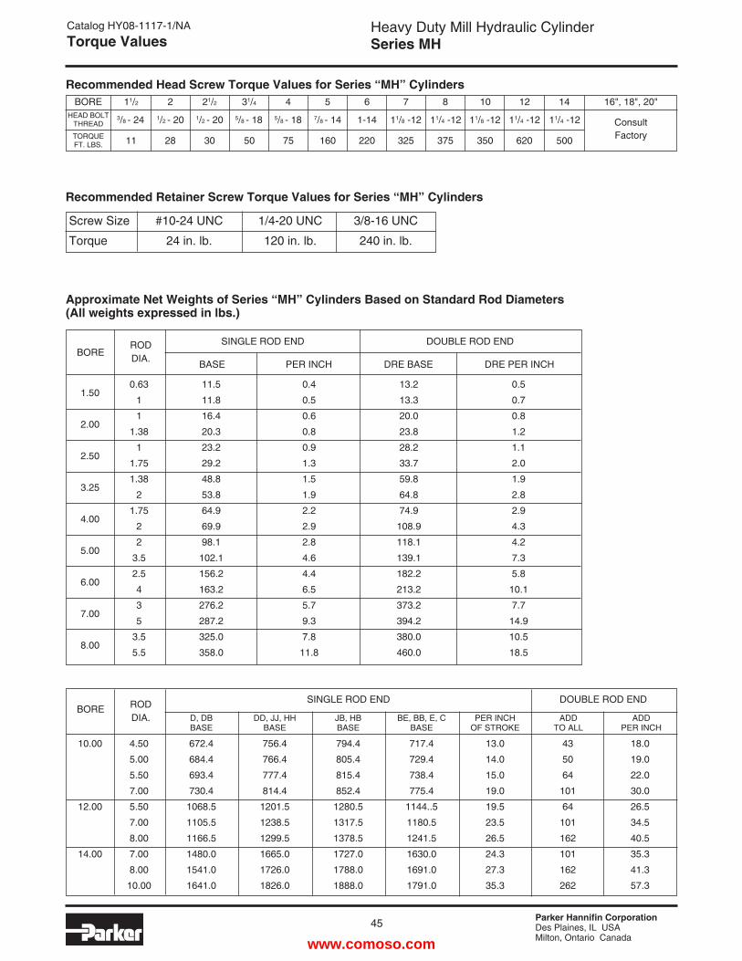
Parker Hannifin CorporationDes Plaines, IL USAMilton, Ontario Canada
Heavy Duty Mill Hydraulic CylinderSeries MH
45
Catalog HY08-1117-1/NATorque Values
Recommended Head Screw Torque Values for Series “MH” Cylinders
Approximate Net Weights of Series “MH” Cylinders Based on Standard Rod Diameters(All weights expressed in lbs.)
BOREHEAD BOLT
THREAD
TORQUEFT. LBS.
11/2 2 21/2 31/4 4 5 6 7 8 10 12
2811 30 50 75 160 220 325 375
3/8 - 24 1/2 - 20 1/2 - 20 5/8 - 18 5/8 - 18 7/8 - 14 1-14 11/8 -12 11/4 -12 11/4 -1211/8 -12
620350
14
11/4 -12
500
16", 18", 20"
ConsultFactory
BOREROD DIA.
SINGLE ROD END
BASE PER INCH
DOUBLE ROD END
DRE BASE DRE PER INCH
1.50
2.00
2.50
3.25
4.00
5.00
6.00
7.00
8.00
0.63
1
1
1.38
1
1.75
1.38
2
1.75
2
2
3.5
2.5
4
3
5
3.5
5.5
11.5
11.8
16.4
20.3
23.2
29.2
48.8
53.8
64.9
69.9
98.1
102.1
156.2
163.2
276.2
287.2
325.0
358.0
0.4
0.5
0.6
0.8
0.9
1.3
1.5
1.9
2.2
2.9
2.8
4.6
4.4
6.5
5.7
9.3
7.8
11.8
13.2
13.3
20.0
23.8
28.2
33.7
59.8
64.8
74.9
108.9
118.1
139.1
182.2
213.2
373.2
394.2
380.0
460.0
0.5
0.7
0.8
1.2
1.1
2.0
1.9
2.8
2.9
4.3
4.2
7.3
5.8
10.1
7.7
14.9
10.5
18.5
BORE ROD DIA.
SINGLE ROD END DOUBLE ROD END
10.00
12.00
14.00
4.50
5.00
5.50
7.00
5.50
7.00
8.00
7.00
8.00
10.00
672.4
684.4
693.4
730.4
1068.5
1105.5
1166.5
1480.0
1541.0
1641.0
D, DBBASE
DD, JJ, HHBASE
JB, HBBASE
BE, BB, E, CBASE
PER INCH OF STROKE
ADD TO ALL
ADD PER INCH
756.4
766.4
777.4
814.4
1201.5
1238.5
1299.5
1665.0
1726.0
1826.0
794.4
805.4
815.4
852.4
1280.5
1317.5
1378.5
1727.0
1788.0
1888.0
717.4
729.4
738.4
775.4
1144..5
1180.5
1241.5
1630.0
1691.0
1791.0
13.0
14.0
15.0
19.0
19.5
23.5
26.5
24.3
27.3
35.3
43
50
64
101
64
101
162
101
162
262
18.0
19.0
22.0
30.0
26.5
34.5
40.5
35.3
41.3
57.3
Recommended Retainer Screw Torque Values for Series “MH” Cylinders
Screw Size #10-24 UNC 1/4-20 UNC 3/8-16 UNC
Torque 24 in. lb. 120 in. lb. 240 in. lb.
www.comoso.com
Parker Hannifin CorporationDes Plaines, IL USAMilton, Ontario Canada
46
Heavy Duty Mill Hydraulic CylinderSeries MH
Catalog HY08-1117-1/NACylinder Safety Guide
Before selecting or using Parker (The Company) cylinders or related accessories, it is important that you read, understand and follow the following safety informa-tion. Training is advised before selecting and using The Company’s products.
1.0 General Instructions 1.1 Scope – This safety guide provides instructions for selecting and using
(including assembling, installing, and maintaining) cylinder products. This safety guide is a supplement to and is to be used with the specific Company publications for the specific cylinder products that are being considered for use.
1.2 Fail Safe – Cylinder products can and do fail without warning for many reasons. All systems and equipment should be designed in a fail-safe mode so that if the failure of a cylinder product occurs people and property won’t be endangered.
1.3 Distribution – Provide a free copy of this safety guide to each person responsible for selecting or using cylinder products. Do not select or use The Company’s cylinders without thoroughly reading and understanding this safety guide as well as the specific Company publications for the products considered or selected.
1.4 User Responsibility – Due to very wide variety of cylinder applications and cylinder operating conditions, The Company does not warrant that any particular cylinder is suitable for any specific application. This safety guide does not analyze all technical parameters that must be considered in select-ing a product. The hydraulic and pneumatic cylinders outlined in this catalog are designed to The Company’s design guidelines and do not necessarily meet the design guideline of other agencies such as American Bureau of Shipping, ASME Pressure Vessel Code etc. The user, through its own analysis and testing, is solely responsible for:
• Making the final selection of the cylinders and related accessories. • Determining if the cylinders are required to meet specific design require-
ments as required by the Agency(s) or industry standards covering the design of the user’s equipment.
• Assuring that the user’s requirements are met, OSHA requirements are met, and safety guidelines from the applicable agencies such as but not limited to ANSI are followed and that the use presents no health or safety hazards.
• Providing all appropriate health and safety warnings on the equipment on which the cylinders are used.
1.5 Additional Questions – Call the appropriate Company technical service department if you have any questions or require any additional information. See the Company publication for the product being considered or used, or call 1-800-CPARKER, or go to www.parker.com, for telephone numbers of the appropriate technical service department.
2.0 Cylinder and Accessories Selection 2.1 Seals – Part of the process of selecting a cylinder is the selection of
seal compounds. Before making this selection, consult the “seal information page(s)” of the publication for the series of cylinders of interest.
The application of cylinders may allow fluids such as cutting fluids, wash down fluids etc. to come in contact with the external area of the cylinder. These fluids may attack the piston rod wiper and or the primary seal and must be taken into account when selecting and specifying seal compounds.
Dynamic seals will wear. The rate of wear will depend on many operating factors. Wear can be rapid if a cylinder is mis-aligned or if the cylinder has been improperly serviced. The user must take seal wear into consideration in the application of cylinders.
2.2 Piston Rods – Possible consequences of piston rod failure or separation of the piston rod from the piston include, but are not limited to are:
• Piston rod and or attached load thrown off at high speed. • High velocity fluid discharge. • Piston rod extending when pressure is applied in the piston
retract mode.
Piston rods or machine members attached to the piston rod may move suddenly and without warning as a consequence of other conditions occurring to the machine such as, but not limited to:
• Unexpected detachment of the machine member from the piston rod.
• Failure of the pressurized fluid delivery system (hoses, fittings, valves, pumps, compressors) which maintain cylinder position.
• Catastrophic cylinder seal failure leading to sudden loss of pressurized fluid.
• Failure of the machine control system. Follow the recommendations of the “Piston Rod Selection Chart and Data”
in the publication for the series of cylinders of interest. The suggested piston rod diameter in these charts must be followed in order to avoid piston rod buckling.
Piston rods are not normally designed to absorb bending moments or loads which are perpendicular to the axis of piston rod motion. These additional loads can cause the piston rod to fail. If these types of additional loads are expected to be imposed on the piston rod, their magnitude should be made known to our engineering department.
The cylinder user should always make sure that the piston rod is securely attached to the machine member.
On occasion cylinders are ordered with double rods (a piston rod extended from both ends of the cylinder). In some cases a stop is threaded on to one of the piston rods and used as an external stroke adjuster. On occasions spacers are attached to the machine member connected to the piston rod and also used as a stroke adjuster. In both cases the stops will create a pinch point and the user should consider appropriate use of guards. If these external stops are not perpendicular to the mating contact surface, or if debris is trapped between the contact surfaces, a bending moment will be placed on the piston rod, which can lead to piston rod failure. An external stop will also negate the effect of cushioning and will subject the piston rod to impact loading. Those two (2) conditions can cause piston rod failure. Internal stroke adjusters are available with and without cushions. The use of external stroke adjusters should be reviewed with our engineering department.
The piston rod to piston and the stud to piston rod threaded connections are secured with an anaerobic adhesive. The strength of the adhesive decreases with increasing temperature. Cylinders which can be exposed to tempera-tures above +250°F (+121°C) are to be ordered with a non studded piston rod and a pinned piston to rod joint.
2.3 Cushions – Cushions should be considered for cylinder applications when the piston velocity is expected to be over 4 inches/second.
Cylinder cushions are normally designed to absorb the energy of a linear applied load. A rotating mass has considerably more energy than the same mass moving in a linear mode. Cushioning for a rotating mass application should be review by our engineering department.
2.4 Cylinder Mountings – Some cylinder mounting configurations may have certain limitations such as but not limited to minimum stroke for side or foot mounting cylinders or pressure de-ratings for certain mounts. Carefully review the catalog for these types of restrictions.
Always mount cylinders using the largest possible high tensile alloy steel socket head cap screws that can fit in the cylinder mounting holes and torque them to the manufacturer’s recommendations for their size.
2.5 Port Fittings – Hydraulic cylinders applied with meter out or decelera-tion circuits are subject to intensified pressure at piston rod end.
The rod end pressure is approximately equal to:
operating pressure x effective cap end area effective rod end piston area
Contact your connector supplier for the pressure rating of individual connectors.
3.0 Cylinder and Accessories Installation and Mounting 3.1 Installation 3.1.1 – Cleanliness is an important consideration, and cylinders are
shipped with the ports plugged to protect them from contaminants enter-ing the ports. These plugs should not be removed until the piping is to be installed. Before making the connection to the cylinder ports, piping should be thoroughly cleaned to remove all chips or burrs which might have resulted from threading or flaring operations.
Safety Guide for Selecting and Using Hydraulic, Pneumatic Cylinders and Their Accessories
WARNING: FAILURE OF THE CYLINDER, ITS PARTS, ITS MOUNTING, ITS CONNECTIONS TO OTHER OBJECTS, OR ITS CONTROLS CAN RESULT IN: • Unanticipated or uncontrolled movement of the cylinder or objects connected to it. • Falling of the cylinder or objects held up by it. • Fluid escaping from the cylinder, potentially at high velocity.THESE EVENTS COULD CAUSE DEATH OR PERSONAL INJURY BY, FOR ExAMPLE, PERSONS FALLING FROM HIGH LOCATIONS, BEING CRUSHED OR STRUCK BY HEAVY OR FAST MOVING OBJECTS, BEING PUSHED INTO DANGEROUS EQUIPMENT OR SITUATIONS, OR SLIPPING ON ESCAPED FLUID.
www.comoso.com
Parker Hannifin CorporationDes Plaines, IL USAMilton, Ontario Canada
Heavy Duty Mill Hydraulic CylinderSeries MH
47
Catalog HY08-1117-1/NACylinder Safety Guide
3.1.2 – Cylinders operating in an environment where air drying materials are present such as fast-drying chemicals, paint, or weld splatter, or other hazardous conditions such as excessive heat, should have shields installed to prevent damage to the piston rod and piston rod seals.
3.1.3 – Proper alignment of the cylinder piston rod and its mating component on the machine should be checked in both the extended and retracted positions. Improper alignment will result in excessive rod gland and/or cylinder bore wear. On fixed mounting cylinders attaching the pis-ton rod while the rod is retracted will help in achieving proper alignment.
3.1.4 – Sometimes it may be necessary to rotate the piston rod in order to thread the piston rod into the machine member. This operation must always be done with zero pressure being applied to either side of the piston. Failure to follow this procedure may result in loosening the piston to rod-threaded connection. In some rare cases the turning of the piston rod may rotate a threaded piston rod gland and loosen it from the cylinder head. Confirm that this condition is not occurring. If it does, re-tighten the piston rod gland firmly against the cylinder head.
For double rod cylinders it is also important that when attaching or detaching the piston rod from the machine member that the torque be applied to the piston rod end of the cylinder that is directly attaching to the machine member with the opposite end unrestrained. If the design of the machine is such that only the rod end of the cylinder opposite to where the rod attaches to the machine member can be rotated, consult the factory for further instructions.
3.2 Mounting Recommendations 3.2.1 – Always mount cylinders using the largest possible high tensile
alloy steel socket head screws that can fit in the cylinder mounting holes and torque them to the manufacturer’s recommendations for their size.
3.2.2 – Side-Mounted Cylinders – In addition to the mounting bolts, cylinders of this type should be equipped with thrust keys or dowel pins located so as to resist the major load.
3.2.3 – Tie Rod Mounting – Cylinders with tie rod mountings are recom-mended for applications where mounting space is limited. The standard tie rod extension is shown as BB in dimension tables. Longer or shorter extensions can be supplied. Nuts used for this mounting style should be torqued to the same value as the tie rods for that bore size.
3.2.4 – Flange Mount Cylinders – The controlled diameter of the rod gland extension on head end flange mount cylinders can be used as a pilot to locate the cylinders in relation to the machine. After align-ment has been obtained, the flanges may be drilled for pins or dowels to prevent shifting.
3.2.5 – Trunnion Mountings – Cylinders require lubricated bearing blocks with minimum bearing clearances. Bearing blocks should be carefully aligned and rigidly mounted so the trunnions will not be subjected to bending moments. The rod end should also be pivoted with the pivot pin in line and parallel to axis of the trunnion pins.
3.2.6 – Clevis Mountings – Cylinders should be pivoted at both ends with centerline of pins parallel to each other. After cylinder is mounted, be sure to check to assure that the cylinder is free to swing through its working arc without interference from other machine parts.
4.0 Cylinder and Accessories Maintenance, Troubleshooting and Replacement
4.1 Storage – At times cylinders are delivered before a customer is ready to install them and must be stored for a period of time. When storage is required the following procedures are recommended.
4.1.1 – Store the cylinders in an indoor area which has a dry, clean and noncorrosive atmosphere. Take care to protect the cylinder from both internal corrosion and external damage.
4.1.2 – Whenever possible cylinders should be stored in a vertical posi-tion (piston rod up). This will minimize corrosion due to possible conden-sation which could occur inside the cylinder. This will also minimize seal damage.
4.1.3 – Port protector plugs should be left in the cylinder until the time of installation.
4.1.4 – If a cylinder is stored full of hydraulic fluid, expansion of the fluid due to temperature changes must be considered. Installing a check valve with free flow out of the cylinder is one method.
4.1.5 – When cylinders are mounted on equipment that is stored outside for extended periods, exposed unpainted surfaces, e.g. piston rod, must be coated with a rust-inhibiting compound to prevent corrosion.
4.2 Cylinder Trouble Shooting
4.2.1 – External Leakage 4.2.1.1 – Rod seal leakage can generally be traced to worn or
damaged seals. Examine the piston rod for dents, gouges or score marks, and replace piston rod if surface is rough.
Rod seal leakage could also be traced to gland wear. If clearance is excessive, replace rod bushing and seal. Rod seal leakage can also be traced to seal deterioration. If seals are soft or gummy or brittle, check compatibility of seal material with lubricant used if air cylinder, or operating fluid if hydraulic cylinder. Replace with seal material, which is compatible with these fluids. If the seals are hard or have lost elasticity, it is usually due to exposure to temperatures in excess of 165°F. (+74°C). Shield the cylinder from the heat source to limit temperature to 350°F. (+177°C.) and replace with fluorocarbon seals.
4.2.1.2 – Cylinder body seal leak can generally be traced to loose tie rods. Torque the tie rods to manufacturer’s recommendation for that bore size.
Excessive pressure can also result in cylinder body seal leak. Determine maximum pressure to rated limits. Replace seals and retorque tie rods as in paragraph above. Excessive pressure can also result in cylinder body seal leak. Determine if the pressure rating of the cylinder has been exceeded. If so, bring the operating pressure down to the rating of the cylinder and have the tie rods replaced.
Pinched or extruded cylinder body seal will also result in a leak. Replace cylinder body seal and retorque as in paragraph above.
Cylinder body seal leakage due to loss of radial squeeze which shows up in the form of flat spots or due to wear on the O.D. or I.D. – Either of these are symptoms of normal wear due to high cycle rate or length of service. Replace seals as per paragraph above.
4.2.2 – Internal Leakage 4.2.2.1 – Piston seal leak (by-pass) 1 to 3 cubic inches per minute
leakage is considered normal for piston ring construction. Virtually no static leak with lipseal type seals on piston should be expected. Piston seal wear is a usual cause of piston seal leakage. Replace seals as required.
4.2.2.2 – With lipseal type piston seals excessive back pressure due to over-adjustment of speed control valves could be a direct cause of rapid seal wear. Contamination in a hydraulic system can result in a scored cylinder bore, resulting in rapid seal wear. In either case, replace piston seals as required.
4.2.2.3 – What appears to be piston seal leak, evidenced by the fact that the cylinder drifts, is not always traceable to the piston. To make sure, it is suggested that one side of the cylinder piston be pressurized and the fluid line at the opposite port be disconnected. Observe leakage. If none is evident, seek the cause of cylinder drift in other component parts in the circuit.
4.2.3 – Cylinder Fails to Move the Load 4.2.3.1 – Pneumatic or hydraulic pressure is too low. Check the
pressure at the cylinder to make sure it is to circuit requirements. 4.2.3.2 – Piston Seal Leak – Operate the valve to cycle the cylinder
and observe fluid flow at valve exhaust ports at end of cylinder stroke. Replace piston seals if flow is excessive.
4.2.3.3 – Cylinder is undersized for the load – Replace cylinder with one of a larger bore size.
4.3 Erratic or Chatter Operation 4.3.1 – Excessive friction at rod gland or piston bearing due to load
misalignment – Correct cylinder-to-load alignment. 4.3.2 – Cylinder sized too close to load requirements – Reduce load or
install larger cylinder. 4.3.3 – Erratic operation could be traced to the difference between static
and kinetic friction. Install speed control valves to provide a back pres-sure to control the stroke.
4.4 Cylinder Modifications, Repairs, or Failed Component – Cylinders as shipped from the factory are not to be disassembled and or modified. If cylinders require modifications, these modifications must be done at company locations or by The Company’s certified facilities. The Cylinder Division Engineering Department must be notified in the event of a mechani-cal fracture or permanent deformation of any cylinder component (excluding seals). This includes a broken piston rod, tie rod, mounting accessory or any other cylinder component. The notification should include all operation and application details. This information will be used to provide an engineered repair that will prevent recurrence of the failure.
It is allowed to disassemble cylinders for the purpose of replacing seals or seal assemblies. However, this work must be done by strictly following all the instructions provided with the seal kits.
www.comoso.com
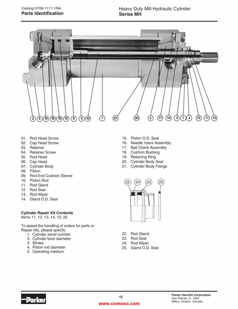
Parker Hannifin CorporationDes Plaines, IL USAMilton, Ontario Canada
48
Heavy Duty Mill Hydraulic CylinderSeries MH
2 6 16 18 19 15 8 9 10 7 21 20 5 17 14 3 1 4 11 1312
Cylinder Repair Kit ContentsItems 11, 12, 13, 14, 15, 20
To speed the handling of orders for parts orRepair kits, please specify: 1. Cylinder serial number 2. Cylinder bore diameter 3. Stroke 4. Piston rod diameter 5. Operating medium
01. Rod Head Screw02. Cap Head Screw03. Retainer04. Retainer Screw05. Rod Head06. Cap Head07. Cylinder Body08. Piston09. Rod End Cushion Sleeve10. Piston Rod 11. Rod Gland 12. Rod Seal 13. Rod Wiper14. Gland O.D. Seal
15. Piston O.D. Seal16. Needle Valve Assembly17. Ball Check Assembly18. Cushion Bushing19. Retaining Ring20. Cylinder Body Seal21. Cylinder Body Flange
Catalog HY08-1117-1/NAParts Identification
22. Rod Gland23. Rod Seal24. Rod Wiper25. Gland O.D. Seal
22 24 23 25
www.comoso.com
Parker Hannifin CorporationDes Plaines, IL USAMilton, Ontario Canada
Heavy Duty Mill Hydraulic CylinderSeries MH
Catalog HY08-1117-1/NAOffer of Sale
The items described in this document and other documents or descriptions provided by Parker Hannifin Corporation, its subsidiaries and Divisions (“Com-pany”) and its authorized distributors, are hereby offered for sale at prices to be established by the Company, its subsidiaries and its authorized distributors. This offer and its acceptance by any customer (“Buyer”) shall be governed by all of the following Terms and Conditions. Buyer’s order for any such item, when communicated to the Company, its subsidiary or an authorized distributor (“Seller”) verbally or in writing, shall constitute acceptance of this offer.
1. Terms and Conditions of Sale: All descriptions, quotations, proposals, offers, acknowledgments, acceptances and sales of Seller’s products are subject to and shall be governed exclusively by the terms and conditions stated herein. Buyer’s acceptance of any offer to sell is limited to these terms and conditions. Any terms or conditions in addition to, or inconsistent with those stated herein, proposed by Buyer in any acceptance of an offer by Seller, are hereby objected to. No such additional, different or inconsistent terms and conditions shall become part of the contract between Buyer and Seller unless expressly accepted in writing by Seller. Seller’s acceptance of any offer to purchase by Buyer is expressly conditional upon Buyer’s assent to all the terms and conditions stated herein, including any terms in addition to, or inconsistent with those contained in Buyer’s offer. Acceptance of Seller’s products shall in all events constitute such assent.2. Payment: Payment shall be made by Buyer net 30 days from the date of delivery of the items purchased hereunder. Amounts not timely paid shall bear interest at the maximum rate permitted by law for each month or portion thereof that the Buyer is late in making payment. Any claims by Buyer for omissions or shortages in a shipment shall be waived unless Seller receives notice thereof within 30 days after Buyer’s receipt of the shipment.3. Delivery: Unless otherwise provided on the face hereof, delivery shall be made F.O.B. Seller’s plant. Regardless of the method of delivery, how-ever, risk of loss shall pass to Buyer upon Seller’s delivery to a carrier. Any delivery dates shown are approximate only and Seller shall have no liability for any delays in delivery.4. Warranty: Seller warrants that the items sold hereunder shall be free from defects in material or workmanship for a period of 18 months from date of shipment from the Company. THIS WARRANTY COMPRISES THE SOLE AND ENTIRE WARRANTY PERTAINING TO ITEMS PROVIDED HEREUNDER. SELLER MAKES NO OTHER WARRANTY, GUARANTEE, OR REPRESENTATION OF ANY KIND WHATSOEVER. ALL OTHER WARRANTIES, INCLUDING BUT NOT LIMITED TO, MERCHANTABILITY AND FITNESS FOR PURPOSE, WHETHER EXPRESS, IMPLIED, OR ARISING BY OPERATION OF LAW, TRADE USAGE, OR COURSE OF DEALING ARE HEREBY DISCLAIMED.NOTWITHSTANDING THE FOREGOING, THERE ARE NO WARRAN-TIES WHATSOEVER ON ITEMS BUILT OR ACQUIRED WHOLLY OR PARTIALLY, TO BUYER’S DESIGN OR SPECIFICATIONS.5. Limitation of Remedy: SELLER’S LIABILITY ARISING FROM OR IN ANY WAY CONNECTED WITH THE ITEMS SOLD OR THIS CONTRACT SHALL BE LIMITED EXCLUSIVELY TO REPAIR OR REPLACEMENT OF THE ITEMS SOLD OR REFUND OF THE PURCHASE PRICE PAID BY BUYER, AT SELLER’S SOLE OPTION. IN NO EVENT SHALL SELLER BE LIABLE FOR ANY INCIDENTAL, CONSEQUENTIAL OR SPECIAL DAMAGES OF ANY KIND OR NATURE WHATSOEVER, INCLUDING BUT NOT LIMITED TO LOST PROFITS ARISING FROM OR IN ANY WAY CONNECTED WITH THIS AGREEMENT OR ITEMS SOLD HEREUNDER, WHETHER ALLEGED TO ARISE FROM BREACH OF CONTRACT, EXPRESS OR IMPLIED WARRANTY, OR IN TORT, INCLUDING WITHOUT LIMITATION, NEGLIGENCE, FAILURE TO WARN OR STRICT LIABILITY.6. Changes, Reschedules and Cancellations: Buyer may request to modify the designs or specifications for the items sold hereunder as well as the quantities and delivery dates thereof, or may request to cancel all or part of this order, however, no such requested modification or cancellation shall become part of the contract between Buyer and Seller unless accepted by Seller in a written amendment to this Agreement. Acceptance of any such requested modification or cancellation shall be at Seller’s discretion, and shall be upon such terms and conditions as Seller may require.7. Special Tooling: A tooling charge may be imposed for any special tooling, including without limitations, dies, fixtures, molds and patterns, acquired to manufacture items sold pursuant to this contract. Such special tooling shall be and remain Seller’s property notwithstanding payment of any charges by Buyer. In no event will Buyer acquire any interest in apparatus belonging to Seller which is utilized in the manufacture of the items sold hereunder, even if such apparatus has been specially converted or adapted for such manu-facture and notwithstanding any charges paid by Buyer. Unless otherwise agreed, Seller shall have the right to alter, discard or otherwise dispose of any special tooling or other property in its sole discretion at any time.
8. Buyer’s Property: Any designs, tools, patterns, materials, drawings, confidential information or equipment furnished by Buyer, or any other items which become Buyer’s property, may be considered obsolete and may be destroyed by Seller after two (2) consecutive years have elapsed without Buyer placing an order for the items which are manufactured using such property. Seller shall not be responsible for any loss or damage to such property while it is in Seller’s possession or control.9. Taxes: Unless otherwise indicated on the face hereof, all prices and charges are exclusive of excise, sales, use, property, occupational or like taxes which may be imposed by any taxing authority upon the manufacture, sale or delivery of the items sold hereunder. If any such taxes must be paid by Seller or if Seller is liable for the collection of such tax, the amount thereof shall be in addition to the amounts for the items sold. Buyer agrees to pay all such taxes or to reimburse Seller therefore upon receipt of its invoice. If Buyer claims exemption from any sales, use or other tax imposed by any taxing authority, Buyer shall save Seller harmless from and against any such tax, together with any interest or penalties thereon which may be assessed if the items are held to be taxable.10. Indemnity For Infringement of Intellectual Property Rights: Seller shall have no liability for infringement of any patents, trademarks, copyrights, trade dress, trade secrets or similar rights except as provided in this Part 10. Seller will defend and indemnify Buyer against allegations of infringe-ment of U.S. patents, U.S. trademarks, copyrights, trade dress and trade secrets (hereinafter “Intellectual Property Rights”). Seller will defend at its expense and will pay the cost of any settlement or damages awarded in an action brought against Buyer based on an allegation that an item sold pursuant to this contract infringes the Intellectual Property Rights of a third party. Seller’s obligation to defend and indemnify Buyer is contingent on Buyer notifying Seller within ten (10) days after Buyer becomes aware of such allegations of infringement, and Seller having sole control over the defense of any allegations or actions including all negotiations for settle-ment or compromise. If an item sold hereunder is subject to a claim that it infringes the Intellectual Property Rights of a third party, Seller may, at its sole expense and option, procure for Buyer the right to continue using said item, replace or modify said item so as to make it noninfringing, or offer to accept return of said item and return the purchase price less a reasonable allowance for depreciation. Notwithstanding the foregoing, Seller shall have no liability for claims of infringement based on information provided by Buyer, or directed to items delivered hereunder for which the designs are specified in whole or part by Buyer, or infringements resulting from the modification, combination or use in a system of any item sold hereunder. The foregoing provisions of this Part 10 shall constitute Seller’s sole and exclusive liability and Buyer’s sole and exclusive remedy for infringement of Intellectual Property Rights.If a claim is based on information provided by Buyer or if the design for an item delivered hereunder is specified in whole or in part by Buyer, Buyer shall defend and indemnify Seller for all costs, expenses or judgements resulting from any claim that such item infringes any patent, trademark, copyright, trade dress, trade secret or any similar right.11. Force Majeure: Seller does not assume the risk of and shall not be liable for delay or failure to perform any of Seller’s obligations by reason of circumstances beyond the reasonable control of Seller (hereinafter “Events of Force Majeure”). Events of Force Majeure shall include without limita-tion, accidents, acts of God, strikes or labor disputes, acts, laws, rules or regulations of any government or government agency, fires, floods, delays or failures in delivery of carriers or suppliers, shortages of materials and any other cause beyond Seller’s control.12. Entire Agreement/Governing Law: The terms and conditions set forth herein, together with any amendments, modifications and any different terms or conditions expressly accepted by Seller in writing, shall constitute the entire Agreement concerning the items sold, and there are no oral or other representations or agreements which pertain thereto. This Agree-ment shall be governed in all respects by the law of the State of Ohio. No actions arising out of sale of the items sold hereunder or this Agreement may be brought by either party more than two (2) years after the cause of action accrues.
Offer of Sale
©®2002 Parker Hannifin Corporation Printed in U.S.A. September, 2006
www.comoso.com

Catalog HY08-1117-1/NA05/08
Parker Hannifin CorporationCylinder Division500 South Wolf RoadDes Plaines, IL 60016 USAphone (847) 298-2400fax (800) 892-1008www.parker.com/cylinder
Parker Hannifin Corporation Motion and Control Division160 Chisholm Drive Milton, ON Canada L9T 3G9 direct (905) 693-3000 fax (905) 876-1958 www.parker.com
www.comoso.com
Related Documents