PRECISION ENERGY METER METER USER MANUAL

Welcome message from author
This document is posted to help you gain knowledge. Please leave a comment to let me know what you think about it! Share it to your friends and learn new things together.
Transcript

PRECISION ENERGY METER
METER USER MANUAL

ELKOR TECHNOLOGIES INC. - Page 2 - WattsOn-Mark II – USER MANUAL

ELKOR TECHNOLOGIES INC. - Page 3 - WattsOn-Mark II – USER MANUAL
Installation Considerations
Installation and maintenance of the WattsOn device must only be performed by qualified, competent personnel who have appropriate training and experience with electrical high voltage and current
installations. The WattsOn device must be installed in accordance with all Local and National Electrical Safety Codes.
WARNING
Failure to observe the following may result in severe injury or death:
During normal operation of this device, hazardous voltages are present on the input terminals of the device and
throughout the connected power lines, including any potential transformers (PTs). With their primary circuit energized, current transformers (CTs) may generate high voltage when their secondary windings are open.
Follow standard safety precautions while performing any installation or service work (i.e. remove line fuses, short
CT secondaries, etc).
This device is not intended for protection applications.
Do not HIPOT and/or dielectric test any of the digital outputs. Refer to this manual for the maximum voltage level
the meter can withstand.
Do not exceed rated input signals as it may permanently damage the device.
The power supply input should be connected via a rated 12-35 VDC / 24VAC power supply and properly isolated
from the line voltage.
Danger
Line voltages up to 600 VRMS may be present on the input terminals of the device and throughout the connected line circuits during normal operation. These voltages may cause severe injury or death.
Installation and servicing must be performed only by qualified, properly trained personnel.
Limitation of Liability
Elkor Technologies Inc. (“Elkor”) reserves the right to make changes to its products and/or their specifications without notice. Elkor strongly recommends obtaining the latest version of the device specifications to assure the most current
information is available to the customer. Specifications and manual are available at http://www.elkor.net
Elkor assumes no liability for applications assistance, customer’s system design, or infringement of patents or copyrights
of third parties by/or arising from the use of Elkor’s devices.
ELKOR TECHNOLOGIES INC. SHALL NOT BE LIABLE FOR CONSEQUENTIAL DAMAGES SUSTAINED IN CONNECTION WITH ELKOR PRODUCTS, EXCEPT TO THE EXTENT PROHIBITED BY APPLICABLE LAW. FURTHERMORE, ELKOR NEITHER
ALLOWS NOR AUTHORIZES ANY OTHER PERSON TO ASSUME FOR IT ANY SUCH OBLIGATION OR LIABILITY.
Although the information contained in this document is believed to be accurate, Elkor assumes no responsibility for any
errors which may exist in this publication.

ELKOR TECHNOLOGIES INC. - Page 4 - WattsOn-Mark II – USER MANUAL
TABLE OF CONTENTS Installation Considerations ........................................................................................................................................ 3 WARNING................................................................................................................................................................ 3 Limitation of Liability ................................................................................................................................................ 3
Table of Contents .............................................................................................................................................. 4 1. Introduction .............................................................................................................................................. 5
1.1. Electrical Wiring ................................................................................................................................................ 5 1.2. Disclosure ......................................................................................................................................................... 5 1.3. Revision History ................................................................................................................................................ 5 1.4. Warranty .......................................................................................................................................................... 5 1.5. Product Description ........................................................................................................................................... 5
2. Specifications ............................................................................................................................................ 6 2.1. Indicators ......................................................................................................................................................... 7
3. Installation................................................................................................................................................ 8 3.1. Grounding Considerations .................................................................................................................................. 8 3.2. Power Supply .................................................................................................................................................... 8 3.3. Line Circuits Wiring ............................................................................................................................................ 8 3.4. Fusing of Voltage Sensing Inputs ....................................................................................................................... 8 3.5. Enclosure Mounting ........................................................................................................................................... 8 3.6. Commissioning Flowchart .................................................................................................................................. 9 3.7. Digital Communications ................................................................................................................................... 10
4. Communication ....................................................................................................................................... 11 4.1. Modbus Protocol ............................................................................................................................................. 11 4.2. Modbus Functions ........................................................................................................................................... 11
5. Register Map ........................................................................................................................................... 13 5.1. Register Addressing Conventions ...................................................................................................................... 13 5.2. Register Size ................................................................................................................................................... 13 5.3. Data Types ..................................................................................................................................................... 13 5.4. Instantaneous Data Registers .......................................................................................................................... 14 5.5. Accumulated Data Registers ............................................................................................................................. 15 5.6. Configuration and Status Registers ................................................................................................................... 21 5.7. System Registers ............................................................................................................................................. 28 5.8. Relay Output Configuration Registers ............................................................................................................... 31
6. Customizing the Register Map ................................................................................................................ 33 7. Firmware Updates and the Bootloader ................................................................................................... 35 8. Appendix A, Wiring Diagrams ................................................................................................................. 36
8.1. Four-Wire (Wye) Wiring Diagram ..................................................................................................................... 36 8.2. Three-Wire (Delta) Wiring Diagram (Three CTs) ................................................................................................ 37 8.3. Three-Wire (Delta) Wiring Diagram (Two CTs) .................................................................................................. 38 8.4. Split-Phase Wiring Diagram .............................................................................................................................. 39 8.5. CT Wiring Notes .............................................................................................................................................. 40
9. Appendix B, Modbus Protocol Details ..................................................................................................... 41 9.1. Modbus Frames ............................................................................................................................................... 41 9.2. Cyclic Redundancy Checksum .......................................................................................................................... 41 9.3. Read Holding Registers .................................................................................................................................... 42 9.4. Read Input Registers ....................................................................................................................................... 42 9.5. Write Single Register ....................................................................................................................................... 42 9.6. Write Multiple Registers ................................................................................................................................... 42 9.7. Mask Write Register ........................................................................................................................................ 43 9.8. Read/Write Multiple Registers .......................................................................................................................... 43 9.9. Diagnostic Functions ........................................................................................................................................ 44 9.10. Get Comm Event Counter............................................................................................................................... 46 9.11. Report Slave ID ............................................................................................................................................. 46

ELKOR TECHNOLOGIES INC. - Page 5 - WattsOn-Mark II – USER MANUAL
1. INTRODUCTION
1.1. Electrical Wiring
Because of possible electrical shock or fire hazards, connection of this equipment should only be made by qualified personnel in compliance with the applicable electrical codes and standards.
1.2. Disclosure
This publication contains information proprietary to Elkor Technologies Inc. No part of this publication may be reproduced,
in any form, without prior written consent from Elkor Technologies Inc.
1.3. Revision History
Version Date Changes
Revision 1 October 2014 Original Version
Revision 2 December 2014 Clarified reserved registers in tables from section 5.4.1 through to 5.5.4. Corrected default threshold voltage in section 2.1 from 5V to 20V. Corrected frequency channel selection in section 5.6.15 to state that changes occur on voltages below 5V
Revision 3 February 2015 Corrected description of Report Slave ID in Appendix B to include the byte count
Revision 4 September 2015 Added Total Capacitive/Reactive Energy (FW > v10.52)
1.4. Warranty
The WattsOn-Mark II is warranted against defective material and workmanship. During the warranty period Elkor will repair or replace, at its option, all defective equipment that is returned freight prepaid. There will be no charge for repair
provided there is no evidence that the equipment has been mishandled or abused. If the equipment is found to be in
proper working order, a service fee will be billed to the customer. Warranty claims must be made via the original purchaser.
Standard Warranty duration is one (1) year from date of sale. Extended warranties are available to OEMs.
1.5. Product Description
The WattsOn-Mark II Precision Energy Meter utilizes advanced metering technology to implement a multi-functional
power and energy meter into a small, cost-effective package. WattsOn-Mark II incorporates three meters into one to
provide a unique solution for monitoring up to single phase, split phase and three phase loads.
The meter provides comprehensive per phase data, as well as cumulative data, including Volts, Amps, Real Power, Reactive Power, Apparent Power, Voltage Angle, Power Factor and Frequency, Quadrant, Import/Export/Net Wh/VAh and
per Quadrant VARh.
WattsOn-Mark II features full four-quadrant metering, and all parameters are metered and accumulated on a per-phase
basis. Additionally, the meter may be configured with per-phase CT ratios allowing for metering asymmetrical loads such as individual building branch circuits. Therefore, it is possible to use different CT sizes and ratios on each input.
The unit accepts up to 600V (line-to-line) directly without needing potential transformers. It may be configured for use
with 333mV output CTs, mA output CTs (such as Elkor’s "safe" mA split and solid core CTs) or industry standard 5A CTs.
The WattsOn-Mark II meter features a proven high performance metering architecture, which allows for accurate and
extremely high resolution measurements over a very wide dynamic range input. The data is updated up to two times per second. The true-RMS inputs may be used even with distorted waveforms such as those generated by variable frequency
drives and SCR loads.
Information is available via the RS-485 (Modbus RTU) output port. In addition, two solid-state relay outputs are available
and may be software configured for Wh pulse outputs, or alarm triggers, as well as direction of power. An on-board graphic LCD display, real-time clock and data logging is optionally available.

ELKOR TECHNOLOGIES INC. - Page 6 - WattsOn-Mark II – USER MANUAL
2. SPECIFICATIONS Inputs
Control Power Input Rating 12-35V VDC / 24VAC, 100 mA max
System Types Supported 120/208V Delta, Wye 277/480V Delta, Wye 347/600V Delta, Wye Single-phase installations up to 347V RMS Split-phase (two phase) installations
Frequency 40-70 Hz
Voltage Input Rating 5 to 347V L-N (600 V L-L)
Voltage Continued Overload Rating 20%
Voltage Absolute Maximum Rating 450V L-N, 780V L-L
Voltage Input Impedance 1.5MΩ (line-to-neutral) minimum, 3.0MΩ (line-to-line) minimum
Voltage Wire Size AWG 30-12, solid / stranded (AWG 16-22 recommended)
Current Input Rating Up to 200 mA RMS (–mA model) Up to 333 mV RMS (–mV model) Up to 10A RMS (–5A model)
Current Continued Overload Rating +20%
Current Absolute Maximum Rating 400 mA RMS (–mA model) 666 mV RMS (–mV model) 20A RMS (–5A model)
Current Burden/Input Impedance 1.5Ω total maximum(–mA model)
800kΩ minimum, 1.2MΩ typical (–mV model)
0.05Ω total maximum (–5A model)
Current Wire Size AWG 24-12, solid / stranded (AWG12-16 recommended for 5A CTs)
Tightening Torque 7.0 Lb-In (Voltage), 4.4 Lb-In (Other)
Outputs
Serial RS-485 2-wire Modbus RTU, 9600 (default) to 230400 baud Elkor Expansion Bus Port
Relay 2x Solid-State Relay Outputs (100 mA @ 50V max)
Indicators LEDs for: Status, Voltage, Current, Relay State, Communication
Display Back-lit Graphic LCD Display 128x32 (–DL models only)
Accuracy
Current (A) 0.05% typical 0.1% max
Voltage, Line-to-Neutral (V) 0.1% typical 0.2% max
Voltage, Line-to-Line (V) 0.2% typical 0.3% max
Real Power (W) 0.1% typical 0.2% max
Apparent Power (VA) 0.1% typical 0.2% max
Reactive Power (VAR) 0.1% typical 0.2% max
Energy 0.1% typical 0.2% max
Power Factor 0.2% max
Frequency 0.01% max
Sampling Rate 2 KHz
Data Update Time 2 Hz
Environmental
Operating Temperature –40°C to +70°C
Storage Temperature –65°C to +85°C
Humidity 10 to 90% non-condensing
Mechanical
Mass 0.15 kg (–mA and –mV models) - 0.23 kg (–5A-DL model)
Mounting DIN Rail mounting 2-point screw mounting
Regulatory
Electromagnetic Emissions FCC part 15 Class B (residential and industrial)
Safety UL 508 listed
Accuracy ANSI C12.20 Class 0.2
ELKOR TECHNOLOGIES INC. - Page 7 - WattsOn-Mark II – USER MANUAL
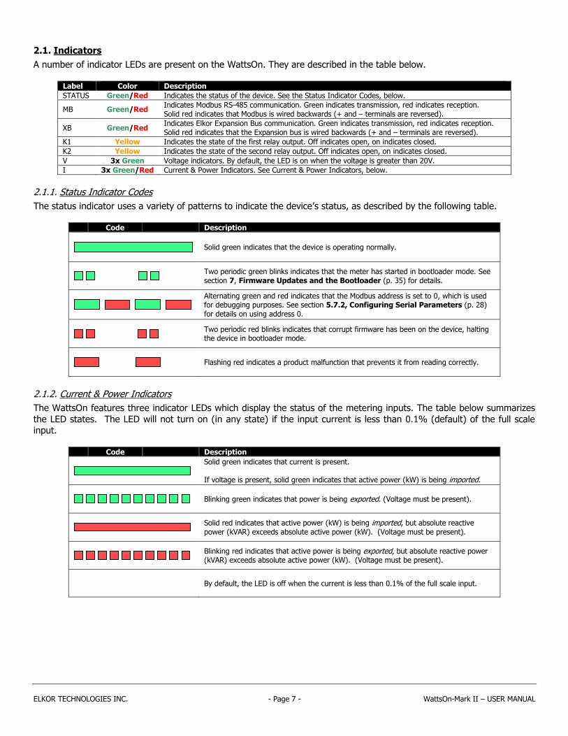
2.1. Indicators
A number of indicator LEDs are present on the WattsOn. They are described in the table below.
Label Color Description
STATUS Green/Red Indicates the status of the device. See the Status Indicator Codes, below.
MB Green/Red Indicates Modbus RS-485 communication. Green indicates transmission, red indicates reception. Solid red indicates that Modbus is wired backwards (+ and – terminals are reversed).
XB Green/Red Indicates Elkor Expansion Bus communication. Green indicates transmission, red indicates reception. Solid red indicates that the Expansion bus is wired backwards (+ and – terminals are reversed).
K1 Yellow Indicates the state of the first relay output. Off indicates open, on indicates closed.
K2 Yellow Indicates the state of the second relay output. Off indicates open, on indicates closed.
V 3x Green Voltage indicators. By default, the LED is on when the voltage is greater than 20V.
I 3x Green/Red Current & Power Indicators. See Current & Power Indicators, below.
2.1.1. Status Indicator Codes
The status indicator uses a variety of patterns to indicate the device’s status, as described by the following table.
Code Description
Solid green indicates that the device is operating normally.
Two periodic green blinks indicates that the meter has started in bootloader mode. See section 7, Firmware Updates and the Bootloader (p. 35) for details.
Alternating green and red indicates that the Modbus address is set to 0, which is used for debugging purposes. See section 5.7.2, Configuring Serial Parameters (p. 28) for details on using address 0.
Two periodic red blinks indicates that corrupt firmware has been on the device, halting the device in bootloader mode.
Flashing red indicates a product malfunction that prevents it from reading correctly.
2.1.2. Current & Power Indicators
The WattsOn features three indicator LEDs which display the status of the metering inputs. The table below summarizes
the LED states. The LED will not turn on (in any state) if the input current is less than 0.1% (default) of the full scale input.
Code Description
Solid green indicates that current is present. If voltage is present, solid green indicates that active power (kW) is being imported.
Blinking green indicates that power is being exported. (Voltage must be present).
Solid red indicates that active power (kW) is being imported, but absolute reactive power (kVAR) exceeds absolute active power (kW). (Voltage must be present).
Blinking red indicates that active power is being exported, but absolute reactive power (kVAR) exceeds absolute active power (kW). (Voltage must be present).
By default, the LED is off when the current is less than 0.1% of the full scale input.

ELKOR TECHNOLOGIES INC. - Page 8 - WattsOn-Mark II – USER MANUAL
3. INSTALLATION
3.1. Grounding Considerations
Output signal ground is usually provided by the controller (RTU, DDC, PLC etc). The output common (GND) IS ISOLATED (3500VAC minimum) from the input reference (N terminal), however the "-" terminal of the input power
supply and the output common (GND) are tied together internally.
3.2. Power Supply
The power supply must be properly isolated from the measurement line to maintain the required isolation voltage. A small dedicated transformer or DIN mount switching power supply is recommended to ensure the best isolation between
system components. Contact Elkor to purchase recommended accessories.
For DC power supplies, the polarity must be observed. For AC power supplies, it must be noted that the RS-485 output
common (G) and “-” power supply terminal are tied together. Care must be taken if multiple devices are powered using one AC supply to prevent shorting the supply.
The power supply may be shared by multiple devices.
3.3. Line Circuits Wiring
The WattsOn meter is a true 'three element' meter that can be used in any electrical system. For four-wire systems ('wye', with distributed neutral) the meter requires current and voltage information from each phase, therefore three
current transformers (CTs) and three line voltages plus neutral must be wired to the unit.
WattsOn may be used in three wire systems ('delta', without a distributed neutral) as a 'three element' meter (three CTs
required). The 5A meter version may be wired as a 'two element' meter utilizing only two CTs (and two PTs). When no neutral is present, the neutral connection should be omitted.
Standard wiring principles for electricity meters apply to the WattsOn meter, as for any other '3 element' electricity meter.
The polarity of interfacing transformers must be observed. The left terminal of each current input connector is always
associated with the 'X1' wire of the responding CT. Please refer to Appendix A for details on CT wiring.
All mV and mA CTs must be wired independently to the corresponding current inputs (two wires from each CT without shunts or jumpers). mA and mV CTs must NOT be grounded, or interconnected with each other (or any other
components) in any way.
The use of a metering test switch containing fuses for voltage lines and shorting terminals for 5A CTs is recommended. A
pre-assembled Elkor i-BlockTM may be used as a convenient and economical solution.
A CT shorting mechanism is not required for mV and Elkor mA style CTs, since these are voltage clamped, however appropriate protection (fuse or breaker) for input line voltages is required.
See Section 8, Appendix A, Wiring Diagrams (p. 36) for details on wiring the meter for various system configurations.
3.4. Fusing of Voltage Sensing Inputs
The input voltage lines should be protected as per electrical code requirements. This is also good practice to facilitate an easy disconnect means for servicing the meter. In some cases, the voltage may be tapped off of existing fuses or
breakers. If this is not possible, Elkor recommends a 1A or lower fuse (fast acting) for protection of the installation wiring.
The WattsOn voltage inputs are high impedance (> 1.5MΩ) and draw negligible current (less than 0.3mA max).
3.5. Enclosure Mounting
The WattsOn is housed in a UL 94V-0 plastic enclosure intended for either DIN mount installation or wall mounted
installation All of the input (bottom) and output (top) signals are available on the exterior of the enclosure. The unit does not contain any user serviceable parts and thus should not be accessed by the user.

ELKOR TECHNOLOGIES INC. - Page 9 - WattsOn-Mark II – USER MANUAL
3.6. Commissioning Flowchart
The following chart summarizes the procedure to install and set up the WattsOn device for basic use.
Connect up to three current transformers to the current input terminals (bottom-right green) on the device.
Observe the polarity as indicated on the CTs – reversing the leads or mounting the CTs backwards will result in negative power and energy accumulation.
Connect a 12-35 VDC / 24VAC power supply to the device’s black power terminal.
Connect the two or three-wire RS-485 line to the device’s top-right green terminal. The ground wire may be
optional for short distances. The Modbus specification recommends the use of shielded RS-485 cabling. Twisted pair is recommended for noisy environments. Bus termination may be required for complex networks.
Connect the other end of the Modbus line to the Modbus master device (PLC, PC, etc.).
Program the CT Ratio primary (for 5A or millivolt CTs) or turn count (for milliamp CTs) into register 0x500 using
the Modbus master device. See Setting CT Ratios (p. 21) for details. If voltage transformers are being used, program the transformer ratio into register 0x508 and 0x509.
Read the Debug Register 0x509 to test that the communications are functioning correctly. The register should
read 12345 (0x3039 in hexadecimal).
Configure the device’s Modbus address by setting the hardware address switch. The address of each device on the
RS-485 line must be unique. If only one device on the line, it can be left at the default setting (1). Addresses from 1 to 15 can be set via the switch, and if necessary higher addresses can be set over Modbus once communication
is established; see 3.7, Digital Communications (p. 10). The address must not be set to 0 for normal operation.
(below) for details or for higher addresses.
For safety reasons, ensure that any live voltages are turned off while connecting the voltage leads.
Connect line voltage leads to the voltage input terminals (bottom-left green. The device will accept up to 347V L-N (or 600V L-L) without a transformer. For higher voltages, potential transformers are required.
Relay outputs may be wired (for example, with pulse counters).

ELKOR TECHNOLOGIES INC. - Page 10 - WattsOn-Mark II – USER MANUAL
3.7. Digital Communications
The WattsOn has an RS-485 port which communicates using the Modbus RTU protocol.
The RS-485 port comes factory-programmed with the indicated settings below. The baud rate, parity, and stop bit settings can be changed via Modbus; see 5.7.2, Configuring Serial Parameters (p. 28).
Parameter Default Setting
Modbus address 1
Baud rate 9600
Parity None
Data bits 8
Stop bits 1
Every Modbus device on an RS-485 network must be assigned a unique Modbus Address. This address is used to
specifically identify the target device for querying by the master. Valid Modbus addresses are between 1-247.
Using the rotary switch, addresses from 1-15 can be set. The switch indicates numbers as hexadecimal values, with 1-9 being shown as normal, “A” representing 10, “B” representing 11, and so on. When the rotary switch is set to F (15) the
device will instead use an address programmed into the unit. The internally programmed address defaults to 15, to match
the rotary switch setting. See section 5.7.1, Modbus Addresses above 15 (p. 28) for details on setting extended Modbus addresses using Modbus.
Address 0 is not a valid Modbus address; it is used for troubleshooting purposes only. See section 5.7.2, Configuring
Serial Parameters (p. 28) for details on using address 0.

ELKOR TECHNOLOGIES INC. - Page 11 - WattsOn-Mark II – USER MANUAL
4. COMMUNICATION
4.1. Modbus Protocol
The WattsOn communicates using Modbus RTU, a digital communication protocol over an RS-485 port. This protocol is supported by various PC software applications, PLCs, data logging devices, and other Modbus “master” devices, which
can be used to communicate with the WattsOn. The WattsOn is defined as a Modbus “slave” device, meaning that it responds to queries sent by the Modbus “master” device.
A Modbus slave device defines blocks of “registers” that contain information, each with a particular address. Each register
contains a 16-byte field of data which can be read by the master device. The registers defined by the WattsOn are
described in section 5, Register Map (p. 13).
For technical details on the Modbus protocol, see Appendix B, Modbus Protocol Details (p. 41), or see the official Modbus Application Specification available for free from http://www.modbus.org/specs.php.
4.2. Modbus Functions
The WattsOn supports a number of different Modbus functions used to query the device or issue commands. Some Modbus software/devices require the user specify specific Modbus functions. Others are more sophisticated, and will
automatically use the appropriate functions as needed, without requiring detailed knowledge of the Modbus protocol.
4.2.1. Supported Functions
The WattsOn supports the following Modbus functions: Function Name Function Code Description
Read Holding Registers 03 (0x03) Reads the data contained in one or more registers (identical to function 04 on this device).
Read Input Registers 04 (0x04) Reads the data contained in one or more registers (identical to function 03 on this device).
Write Register 06 (0x06) Writes data to a single register.
Diagnostics 08 (0x08)
Return Query Data 00 (0x00) The Diagnostics function is a series of sub-functions that assist in diagnosing communication problems. See Diagnostic Functions (below) for details on each one.
Clear Counters 10 (0x0A)
Bus Message Count 11 (0x0B)
Bus Comm Error Count 12 (0x0C)
Bus Exception Count 13 (0x0D)
Slave Message Count 14 (0x0E)
Get Event Counter 11 (0x0B) Reads a count of successful messages since power-on, excluding function 11 messages.
Write Multiple Registers 16 (0x10) Writes data to one or more registers.
Report Slave ID 17 (0x11) Returns various information used to identify this device. See Slave ID (below).
Write Mask Register 22 (0x16) Modifies data in a single register based on an OR mask and an AND mask.
Read/Write Registers 23 (0x17) Writes data to one or more registers, and then reads data from one or more registers.
Read Device ID 43 (0x2B)/14 (0x0E) Reads various text strings giving device parameters. See Device ID (next page).
4.2.2. Diagnostic Functions
The WattsOn implements various diagnostic functions to assist in verifying and diagnosing communication problems. The Diagnostic function is divided into a number of sub-functions each identified by a sub-function code. The following table
summarizes the diagnostic sub-functions implemented by this device. Description Sub-Function Description
Return Query Data 00 (0x00) Sends dummy data to the device, which is then returned as-is. Used for testing communication.
Clear Counters 10 (0x0A) Clears all counters associated with the communication system, including the Bus Message Counter, the Bus Comm Error Counter, the Bus Exception Counter, the Slave Message Counter, and the Event Counter (also used in function 11).
Bus Message Count 11 (0x0B) Returns the number of messages that the device has detected since power-up. These messages were not necessarily valid or addressed to this device.
Bus Comm Error Count 12 (0x0C) Returns the number of CRC errors detected by the device since power-up. The messages containing these CRC errors were not necessarily addressed to this device.
Bus Exception Count 13 (0x0D) Returns the number of exception responses returned by this device since power-up.
Slave Message Count 14 (0x0E) Returns the count of messages addressed to this device that were received since power-up.

ELKOR TECHNOLOGIES INC. - Page 12 - WattsOn-Mark II – USER MANUAL
4.2.3. Slave ID
The WattsOn implements function 17, Report Slave ID, which returns three separate pieces of information. It returns an ID code identifying this particular device, a status code indicating if the device is running or not, and a null-terminated
text string identifying this particular device. Field Data
ID Code 130
Status 0xFF (ON) when running normally, 0x00 (OFF) when in bootloader mode.
Text String An ASCII text string containing the name of the product, its input configuration (mA, mV, or 5A), and its hardware and software version. The string is null-terminated, meaning a 0 is transmitted after the last character. For example, “Elkor Technologies W2-M1-mA Hardware 1.00 Firmware 1.00”. While in bootloader mode, the string returned contains the bootloader version, for example, “Elkor Technologies Bootloader 1.00”.
4.2.4. Device ID
The WattsOn implements the Read Device ID function, which provides access to various strings that identify various device properties. This is sub-function 14 (0x0E) of function 43 (0x2B), Encapsulated Interface Transport. The WattsOn
implements this function at the highest Conformity Level of 0x83 (basic, regular, and extended identification, stream or
individual access).
Each string, called an “object”, is accessed with a number, called the object ID. The WattsOn defines the following objects, which can be read using this function.
Object Object ID Category Value
VendorName 0 (0x00) Standard (Basic) “Elkor Technologies”
ProductCode 1 (0x01) Standard (Basic) “W2”
MajorMinorRevision 2 (0x02) Standard (Basic) The firmware version of the device, such as “1.00”
VendorUrl 3 (0x03) Standard (Regular) “http://www.elkor.net”
ProductName 4 (0x04) Standard (Regular) “WattsOn-Mark II”
ModelName 5 (0x05) Standard (Regular) The device’s model name, for example, “W2-M1-mA”
UserApplicationName 6 (0x06) Standard (Regular) “Elkor Firmware”
HardwareRevision 128 (0x80) Extended The hardware version on the device, such as “1.00”
BootloaderRevision 129 (0x81) Extended The bootloader version on the device, such as “1.00”
SerialNumber 130 (0x82) Extended The serial number of the device, such as “12345”
DeviceID 131 (0x83) Extended 130

ELKOR TECHNOLOGIES INC. - Page 13 - WattsOn-Mark II – USER MANUAL
5. REGISTER MAP
5.1. Register Addressing Conventions
There are several different conventions for specifying the address of a particular register. Various conventions are used in different software programs, PLCs, and other devices. Three common conventions are described below.
Offsets: Addresses are presented as hexadecimal numbers (shown with the “0x”
prefix) with the first address starting at address 0. This is how addresses are
transmitted digitally over the serial cable, and many software packages describe Modbus addresses.
PLC-style addresses: Addresses are presented as 5-digit decimal numbers, starting
with a “3” or a “4” indicating whether they are considered “input registers” which are read-only, or “holding registers” which are read-write (respectively). The first input
register is defined as 30001, and the first holding register is defined as 40001. For ease of integration, this device treats both Holding Registers and Input Registers as
identical; therefore, either 30000-based addresses or 40000-based addresses will work
with the WattsOn, though only 40000-based addresses can be written to. Many PLCs and some other devices describe Modbus addresses in this manner.
Register numbers: Addresses are presented as decimal numbers, with the first register defined as register 1.
These are similar to the PLC-style addresses described above, without “3” or “4” prefix. Some software packages
describe Modbus addresses in this manner.
The address of each register is presented in the first two styles in this manual. The required convention that is used
depends on the Modbus master software or device.
5.2. Register Size
Modbus registers are defined as each containing 16 bits of information. In this document, some registers are described as being 32-bits wide, rather than 16. In these cases, two consecutive registers are concatenated together in order to obtain
the 32-bit value. Most modern Modbus software and hardware devices understand the notion of 32-bit registers, and will
do this processing, provided the data is configured as a 32-bit register.
Example: Register 0x100 is a 32-bit register. Suppose a read of register 0x100 returns 0x0003, and a read of register 0x101 returns 0x0D40. Concatenate these two registers together to get a hexadecimal
value of 0x00030D40, or a decimal value of 200,000.
By default, the higher-order 16-bit word of a 32-bit register is the register with the lower address, and the lower-order
word is at the higher address. Most Modbus software and devices will interpret 32-bit registers this way. Alternatively, the WattsOn can be configured to reverse the byte ordering, so that the higher-order word is at the higher address, and the
lower-order word is at the lower address. See 5.6.6, Setting 32-bit Endianness (p. 23) for details on how to configure this setting.
5.3. Data Types
Registers contain data in one of four different types. Data types are given in the register tables with a single letter code in the “Type” column to indicate the type. The types are as follows.
Type Code Description
Unsigned Integer
U Positive whole numbers (no sign). Can range from 0 to 65,535 for 16-bit registers, and 0 to 4,294,967,295 for 32-bit registers.
Signed Integer
S Positive or negative whole numbers. Represented in 2’s complement format. Can range from -32,768 to +32,767 for 16-bit registers and -2,147,483,648 to +2,147,483,647 for 32-bit registers.
Floating-Point F Positive or negative decimal numbers. Represented in IEEE 754 format. Can represent values from negative infinity to positive infinity, at decreasing levels of resolution as the number because larger.
Boolean B True or false. False is represented by the value 0, true is represented by the value 1.
Examples
Offset: 0x0 PLC-style: 40001
Register No: 1
Offset: 0x10
PLC-style: 40017 Register No: 17
Offset: 0x200
PLC-style: 40513 Register No: 513

ELKOR TECHNOLOGIES INC. - Page 14 - WattsOn-Mark II – USER MANUAL
5.4. Instantaneous Data Registers
Instantaneous data registers contain the real-time measurements from the input channels on the device, including current, voltage, power, power factor, and frequency. For energy registers, see 5.5, Accumulated Data Registers (p.
15). The instantaneous registers are presented in two different formats, each in a separate block of registers – as floating-point data (for modern systems), and as integer data (for systems which do not support floating-point data). It is
recommended to read the floating-point data if possible, as there is then no need to scale the registers manually.
Both integer and floating-point registers incorporate the CT and PT ratios entered into the configuration registers
described in section 5.6, Configuration and Status Registers (p. 21).
5.4.1. Integer Instantaneous Data Registers
The following registers are 32-bit integer representations of the measured parameters. To allow integer registers to represent decimal numbers, the integer registers are scaled according to a scaling factor. Divide the value read from
these registers by the scaling factor in the Scale column to get a decimal value in the units specified by the Units column.
Example: If you read the value “4501” from the Current A register, divide 4501 by the scaling factor of
1000, to get a value of 4.501 Amps on channel A. Name Offset Address Size Type R/W Units Scale
Active Power Total 0x100 40257 32 S R W 10
Reactive Power Total 0x102 40259 32 S R VAR 10
Apparent Power Total 0x104 40261 32 S R VA 10
Voltage Average 0x106 40263 32 S R V 100
Voltage L-L Average 0x108 40265 32 S R V 100
Current Average 0x10A 40267 32 S R A 1000
System Power Factor 0x10C 40269 32 S R - 10000
System Frequency 0x10E 40271 32 S R Hz 1000
Voltage Phase Angle Average 0x110 40273 32 S R ° 10
System Quadrant 0x112 40275 32 U R - -
Reserved 0x114 40277 32 - R - -
…
Reserved 0x11E 40287 32 - R - -
Voltage A 0x120 40289 32 S R V 100
Voltage B 0x122 40291 32 S R V 100
Voltage C 0x124 40293 32 S R V 100
Voltage AB 0x126 40295 32 S R V 100
Voltage BC 0x128 40297 32 S R V 100
Voltage AC 0x12A 40299 32 S R V 100
Current A 0x12C 40301 32 S R A 1000
Current B 0x12E 40303 32 S R A 1000
Current C 0x130 40305 32 S R A 1000
Active Power A 0x132 40307 32 S R W 10
Active Power B 0x134 40309 32 S R W 10
Active Power C 0x136 40311 32 S R W 10
Reactive Power A 0x138 40313 32 S R VAR 10
Reactive Power B 0x13A 40315 32 S R VAR 10
Reactive Power C 0x13C 40317 32 S R VAR 10
Apparent Power A 0x13E 40319 32 S R VA 10
Apparent Power B 0x140 40321 32 S R VA 10
Apparent Power C 0x142 40323 32 S R VA 10
Power Factor A 0x144 40325 32 S R - 10000
Power Factor B 0x146 40327 32 S R - 10000
Power Factor C 0x148 40329 32 S R - 10000
Voltage Phase Angle AB 0x14A 40331 32 S R ° 10
Voltage Phase Angle BC 0x14C 40333 32 S R ° 10
Voltage Phase Angle AC 0x14E 40335 32 S R ° 10
Quadrant A 0x150 40337 32 U R - -
Quadrant B 0x152 40339 32 U R - -
Quadrant C 0x154 40341 32 U R - -
Sliding Window Power 0x156 40343 32 S R W 10

ELKOR TECHNOLOGIES INC. - Page 15 - WattsOn-Mark II – USER MANUAL
5.4.2. Floating-Point Instantaneous Data Registers
The following registers are 32-bit floating-point representations of the measured parameters, expressed in IEEE 754 format. Unlike the integer registers described above, these registers are capable of representing decimal numbers and
therefore do not require any scaling. Name Offset Address Size Type R/W Units
Active Power Total 0x200 40513 32 F R kW
Reactive Power Total 0x202 40515 32 F R kVAR
Apparent Power Total 0x204 40517 32 F R kVA
Voltage Average 0x206 40519 32 F R V
Voltage L-L Average 0x208 40521 32 F R V
Current Average 0x20A 40523 32 F R A
System Power Factor 0x20C 40525 32 F R -
System Frequency 0x20E 40527 32 F R Hz
Voltage Average Angle 0x210 40529 32 F R °
System Quadrant 0x212 40531 32 F R -
Reserved 0x214 40533 32 - R -
…
Reserved 0x21E 40543 32 - R -
Voltage A 0x220 40545 32 F R V
Voltage B 0x222 40547 32 F R V
Voltage C 0x224 40549 32 F R V
Voltage AB 0x226 40551 32 F R V
Voltage BC 0x228 40553 32 F R V
Voltage AC 0x22A 40555 32 F R V
Current A 0x22C 40557 32 F R A
Current B 0x22E 40559 32 F R A
Current C 0x230 40561 32 F R A
Active Power A 0x232 40563 32 F R kW
Active Power B 0x234 40565 32 F R kW
Active Power C 0x236 40567 32 F R kW
Reactive Power A 0x238 40569 32 F R kVAR
Reactive Power B 0x23A 40571 32 F R kVAR
Reactive Power C 0x23C 40573 32 F R kVAR
Apparent Power A 0x23E 40575 32 F R kVA
Apparent Power B 0x240 40577 32 F R kVA
Apparent Power C 0x242 40579 32 F R kVA
Power Factor A 0x244 40581 32 F R -
Power Factor B 0x246 40583 32 F R -
Power Factor C 0x248 40585 32 F R -
Voltage Angle AB 0x24A 40587 32 F R °
Voltage Angle BC 0x24C 40589 32 F R °
Voltage Angle AC 0x24E 40591 32 F R °
Quadrant A 0x250 40593 32 F R -
Quadrant B 0x252 40595 32 F R -
Quadrant C 0x254 40597 32 F R -
Sliding Window Power 0x256 40599 32 F R kW
5.5. Accumulated Data Registers
Accumulated data registers contain energy data accumulated over time from the input channels on the device, including
real energy, apparent energy, and reactive energy. For instantaneous registers such as power and current, see 5.4,
Instantaneous Data Registers (p. 14).
There are four blocks of accumulated data registers in total. Two blocks reflect resets – they can be reset to 0 at any time. The remaining two blocks do not reflect resets, and retain their total accumulated value despite any number of resets
issued by the user. Revenue-grade metering applications or applications that do not require the ability to reset the meter
should always read the non-resettable registers.

ELKOR TECHNOLOGIES INC. - Page 16 - WattsOn-Mark II – USER MANUAL
Resettable and non-resettable registers each have a floating-point block (for modern systems) and an integer block (for
systems that do not support floating-point data). It is recommended to read the floating-point data if possible, as there is then no need to multiply the results by any scaling factors in that case.
The WattsOn’s internal accumulated energy will never overflow; however, when reading 32-bit integer representations of
the energy registers in combination with large CT or PT ratios, 32-bit integers may not be large enough to contain the
information. To address this problem, the WattsOn has an Energy Integer Divider Register, 0x52E which is applied to the energy values as they are read. By default, this is set to 100. This sets the resolution of the energy registers to 100
Wh/VAh/VARh by default. The maximum resolution is 1 Wh/VAh/VARh (including CT/PT scaling) with the divider set to 1.
This divider can be adjusted if desired, either to accommodate larger CT/PT ratios, or if greater resolution is desired. Multiply the value read from the registers by the value of the Energy Integer Divider register to obtain the units
expressed in the Units column of the following tables. See 5.6.13, Energy Integer Divider (p. 26) for details on the
Energy Integer Divider register.
Example: If you read the value “45” from the Net Energy A register, and “100” from the Energy Integer Divisor register. Multiply 45 by 100 to get a value of 4500 Wh (or 4.5 kW) on channel A.
The floating-point representations of the energy registers do not use the Energy Integer Divider Register, as they can represent arbitrarily large values. For this reason, reading the floating-point registers is recommended. However, their
resolution will decrease as values grow larger.

ELKOR TECHNOLOGIES INC. - Page 17 - WattsOn-Mark II – USER MANUAL
5.5.1. Resettable Integer Accumulated Data Registers
These registers reflect resets made using the Energy Reset register 0x524; see 5.6.8, Resetting Accumulated Energy (p. 24) for details.
Name Offset Address Size Type R/W Units
Net Total Energy (Resettable) 0x1000 44097 32 S R Wh
Total Net Apparent Energy (Resettable) 0x1002 44099 32 S R VAh
Total Import Energy (Resettable) 0x1004 44101 32 S R Wh
Total Export Energy (Resettable) 0x1006 44103 32 S R Wh
Total Import Apparent Energy (Resettable) 0x1008 44105 32 S R VAh
Total Export Apparent Energy (Resettable) 0x100A 44107 32 S R VAh
Q1 Total Reactive Energy (Resettable) 0x100C 44109 32 S R VARh
Q2 Total Reactive Energy (Resettable) 0x100E 44111 32 S R VARh
Q3 Total Reactive Energy (Resettable) 0x1010 44113 32 S R VARh
Q4 Total Reactive Energy (Resettable) 0x1012 44115 32 S R VARh
Q1+Q2 Total Inductive Reactive Energy (Resettable) 0x1014 44117 32 S R VARh
Q3+Q4 Total Capacitive Reactive Energy (Resettable) 0x1016 44119 32 S R VARh
Reserved 0x1018 44121 32 - R -
…
Reserved 0x101E 44127 32 - R -
Net Energy (Resettable) A 0x1020 44129 32 S R Wh
Net Energy (Resettable) B 0x1022 44131 32 S R Wh
Net Energy (Resettable) C 0x1024 44133 32 S R Wh
Net Apparent Energy (Resettable) A 0x1026 44135 32 S R VAh
Net Apparent Energy (Resettable) B 0x1028 44137 32 S R VAh
Net Apparent Energy (Resettable) C 0x102A 44139 32 S R VAh
Import Energy (Resettable) A 0x102C 44141 32 S R Wh
Import Energy (Resettable) B 0x102E 44143 32 S R Wh
Import Energy (Resettable) C 0x1030 44145 32 S R Wh
Export Energy (Resettable) A 0x1032 44147 32 S R Wh
Export Energy (Resettable) B 0x1034 44149 32 S R Wh
Export Energy (Resettable) C 0x1036 44151 32 S R Wh
Import Apparent Energy (Resettable) A 0x1038 44153 32 S R VAh
Import Apparent Energy (Resettable) B 0x103A 44155 32 S R VAh
Import Apparent Energy (Resettable) C 0x103C 44157 32 S R VAh
Export Apparent Energy (Resettable) A 0x103E 44159 32 S R VAh
Export Apparent Energy (Resettable) B 0x1040 44161 32 S R VAh
Export Apparent Energy (Resettable) C 0x1042 44163 32 S R VAh
Q1 Reactive Energy (Resettable) A 0x1044 44165 32 S R VARh
Q1 Reactive Energy (Resettable) B 0x1046 44167 32 S R VARh
Q1 Reactive Energy (Resettable) C 0x1048 44169 32 S R VARh
Q2 Reactive Energy (Resettable) A 0x104A 44171 32 S R VARh
Q2 Reactive Energy (Resettable) B 0x104C 44173 32 S R VARh
Q2 Reactive Energy (Resettable) C 0x104E 44175 32 S R VARh
Q3 Reactive Energy (Resettable) A 0x1050 44177 32 S R VARh
Q3 Reactive Energy (Resettable) B 0x1052 44179 32 S R VARh
Q3 Reactive Energy (Resettable) C 0x1054 44181 32 S R VARh
Q4 Reactive Energy (Resettable) A 0x1056 44183 32 S R VARh
Q4 Reactive Energy (Resettable) B 0x1058 44185 32 S R VARh
Q4 Reactive Energy (Resettable) C 0x105A 44187 32 S R VARh

ELKOR TECHNOLOGIES INC. - Page 18 - WattsOn-Mark II – USER MANUAL
5.5.2. Resettable Floating-Point Accumulated Data Registers
The following registers are 32-bit floating-point representations of the accumulated energy parameters, expressed in IEEE 754 format. These registers reflect resets made using the Energy Reset register 0x524; see 5.6.8, Resetting
Accumulated Energy (p. 24) for details. Name Offset Address Size Type R/W Units
Net Total Energy (Resettable) 0x1100 44353 32 F R kWh
Total Net Apparent Energy (Resettable) 0x1102 44355 32 F R kVAh
Total Import Energy (Resettable) 0x1104 44357 32 F R kWh
Total Export Energy (Resettable) 0x1106 44359 32 F R kWh
Total Import Apparent Energy (Resettable) 0x1108 44361 32 F R kVAh
Total Export Apparent Energy (Resettable) 0x110A 44363 32 F R kVAh
Q1 Total Reactive Energy (Resettable) 0x110C 44365 32 F R kVARh
Q2 Total Reactive Energy (Resettable) 0x110E 44367 32 F R kVARh
Q3 Total Reactive Energy (Resettable) 0x1110 44369 32 F R kVARh
Q4 Total Reactive Energy (Resettable) 0x1112 44371 32 F R kVARh
Q1+Q2 Total Inductive Reactive Energy (Resettable) 0x1114 44373 32 F R VARh
Q3+Q4 Total Capacitive Reactive Energy (Resettable) 0x1116 44375 32 F R VARh
Reserved 0x1118 44377 32 - R -
…
Reserved 0x111E 44383 32 - R -
Net Energy (Resettable) A 0x1120 44385 32 F R kWh
Net Energy (Resettable) B 0x1122 44387 32 F R kWh
Net Energy (Resettable) C 0x1124 44389 32 F R kWh
Net Apparent Energy (Resettable) A 0x1126 44391 32 F R kVAh
Net Apparent Energy (Resettable) B 0x1128 44393 32 F R kVAh
Net Apparent Energy (Resettable) C 0x112A 44395 32 F R kVAh
Import Energy (Resettable) A 0x112C 44397 32 F R kWh
Import Energy (Resettable) B 0x112E 44399 32 F R kWh
Import Energy (Resettable) C 0x1130 44401 32 F R kWh
Export Energy (Resettable) A 0x1132 44403 32 F R kWh
Export Energy (Resettable) B 0x1134 44405 32 F R kWh
Export Energy (Resettable) C 0x1136 44407 32 F R kWh
Import Apparent Energy (Resettable) A 0x1138 44409 32 F R kVAh
Import Apparent Energy (Resettable) B 0x113A 44411 32 F R kVAh
Import Apparent Energy (Resettable) C 0x113C 44413 32 F R kVAh
Export Apparent Energy (Resettable) A 0x113E 44415 32 F R kVAh
Export Apparent Energy (Resettable) B 0x1140 44417 32 F R kVAh
Export Apparent Energy (Resettable) C 0x1142 44419 32 F R kVAh
Q1 Reactive Energy (Resettable) A 0x1144 44421 32 F R kVARh
Q1 Reactive Energy (Resettable) B 0x1146 44423 32 F R kVARh
Q1 Reactive Energy (Resettable) C 0x1148 44425 32 F R kVARh
Q2 Reactive Energy (Resettable) A 0x114A 44427 32 F R kVARh
Q2 Reactive Energy (Resettable) B 0x114C 44429 32 F R kVARh
Q2 Reactive Energy (Resettable) C 0x114E 44431 32 F R kVARh
Q3 Reactive Energy (Resettable) A 0x1150 44433 32 F R kVARh
Q3 Reactive Energy (Resettable) B 0x1152 44435 32 F R kVARh
Q3 Reactive Energy (Resettable) C 0x1154 44437 32 F R kVARh
Q4 Reactive Energy (Resettable) A 0x1156 44439 32 F R kVARh
Q4 Reactive Energy (Resettable) B 0x1158 44441 32 F R kVARh
Q4 Reactive Energy (Resettable) C 0x115A 44443 32 F R kVARh

ELKOR TECHNOLOGIES INC. - Page 19 - WattsOn-Mark II – USER MANUAL
5.5.3. Revenue (Non-Resettable) Integer Accumulated Data Registers
These registers do not reflect resets made using the Energy Reset register. Name Offset Address Size Type R/W Units
Net Total Energy (Revenue) 0x1200 44609 32 S R Wh
Total Net Apparent Energy (Revenue) 0x1202 44611 32 S R VAh
Total Import Energy (Revenue) 0x1204 44613 32 S R Wh
Total Export Energy (Revenue) 0x1206 44615 32 S R Wh
Total Import Apparent Energy (Revenue) 0x1208 44617 32 S R VAh
Total Export Apparent Energy (Revenue) 0x120A 44619 32 S R VAh
Q1 Total Reactive Energy (Revenue) 0x120C 44621 32 S R VARh
Q2 Total Reactive Energy (Revenue) 0x120E 44623 32 S R VARh
Q3 Total Reactive Energy (Revenue) 0x1210 44625 32 S R VARh
Q4 Total Reactive Energy (Revenue) 0x1212 44627 32 S R VARh
Q1+Q2 Total Inductive Reactive Energy (Revenue) 0x1214 44629 32 S R VARh
Q3+Q4 Total Capacitive Reactive Energy (Revenue) 0x1216 44631 32 S R VARh
Reserved 0x1218 44633 32 - R -
…
Reserved 0x121E 44639 32 - R -
Net Energy (Revenue) A 0x1220 44641 32 S R Wh
Net Energy (Revenue) B 0x1222 44643 32 S R Wh
Net Energy (Revenue) C 0x1224 44645 32 S R Wh
Net Apparent Energy (Revenue) A 0x1226 44647 32 S R VAh
Net Apparent Energy (Revenue) B 0x1228 44649 32 S R VAh
Net Apparent Energy (Revenue) C 0x122A 44651 32 S R VAh
Import Energy (Revenue) A 0x122C 44653 32 S R Wh
Import Energy (Revenue) B 0x122E 44655 32 S R Wh
Import Energy (Revenue) C 0x1230 44657 32 S R Wh
Export Energy (Revenue) A 0x1232 44659 32 S R Wh
Export Energy (Revenue) B 0x1234 44661 32 S R Wh
Export Energy (Revenue) C 0x1236 44663 32 S R Wh
Import Apparent Energy (Revenue) A 0x1238 44665 32 S R VAh
Import Apparent Energy (Revenue) B 0x123A 44667 32 S R VAh
Import Apparent Energy (Revenue) C 0x123C 44669 32 S R VAh
Export Apparent Energy (Revenue) A 0x123E 44671 32 S R VAh
Export Apparent Energy (Revenue) B 0x1240 44673 32 S R VAh
Export Apparent Energy (Revenue) C 0x1242 44675 32 S R VAh
Q1 Reactive Energy (Revenue) A 0x1244 44677 32 S R VARh
Q1 Reactive Energy (Revenue) B 0x1246 44679 32 S R VARh
Q1 Reactive Energy (Revenue) C 0x1248 44681 32 S R VARh
Q2 Reactive Energy (Revenue) A 0x124A 44683 32 S R VARh
Q2 Reactive Energy (Revenue) B 0x124C 44685 32 S R VARh
Q2 Reactive Energy (Revenue) C 0x124E 44687 32 S R VARh
Q3 Reactive Energy (Revenue) A 0x1250 44689 32 S R VARh
Q3 Reactive Energy (Revenue) B 0x1252 44691 32 S R VARh
Q3 Reactive Energy (Revenue) C 0x1254 44693 32 S R VARh
Q4 Reactive Energy (Revenue) A 0x1256 44695 32 S R VARh
Q4 Reactive Energy (Revenue) B 0x1258 44697 32 S R VARh
Q4 Reactive Energy (Revenue) C 0x125A 44699 32 S R VARh

ELKOR TECHNOLOGIES INC. - Page 20 - WattsOn-Mark II – USER MANUAL
5.5.4. Revenue (Non-Resettable) Floating-Point Accumulated Data Registers
The following registers are 32-bit floating-point representations of the accumulated energy parameters, expressed in IEEE 754 format. These registers do not reflect resets made using the Energy Reset register.
Name Offset Address Size Type R/W Units
Net Total Energy (Revenue) 0x1300 44865 32 F R kWh
Total Net Apparent Energy (Revenue) 0x1302 44867 32 F R kVAh
Total Import Energy (Revenue) 0x1304 44869 32 F R kWh
Total Export Energy (Revenue) 0x1306 44871 32 F R kWh
Total Import Apparent Energy (Revenue) 0x1308 44873 32 F R kVAh
Total Export Apparent Energy (Revenue) 0x130A 44875 32 F R kVAh
Q1 Total Reactive Energy (Revenue) 0x130C 44877 32 F R kVARh
Q2 Total Reactive Energy (Revenue) 0x130E 44879 32 F R kVARh
Q3 Total Reactive Energy (Revenue) 0x1310 44881 32 F R kVARh
Q4 Total Reactive Energy (Revenue) 0x1312 44883 32 F R kVARh
Q1+Q2 Total Inductive Reactive Energy (Revenue) 0x1314 44885 32 S R VARh
Q3+Q4 Total Capacitive Reactive Energy (Revenue) 0x1316 44887 32 S R VARh
Reserved 0x1318 44889 32 - R -
…
Reserved 0x131E 44895 32 - R -
Net Energy (Revenue) A 0x1320 44897 32 F R kWh
Net Energy (Revenue) B 0x1322 44899 32 F R kWh
Net Energy (Revenue) C 0x1324 44901 32 F R kWh
Net Apparent Energy (Revenue) A 0x1326 44903 32 F R kVAh
Net Apparent Energy (Revenue) B 0x1328 44905 32 F R kVAh
Net Apparent Energy (Revenue) C 0x132A 44907 32 F R kVAh
Import Energy (Revenue) A 0x132C 44909 32 F R kWh
Import Energy (Revenue) B 0x132E 44911 32 F R kWh
Import Energy (Revenue) C 0x1330 44913 32 F R kWh
Export Energy (Revenue) A 0x1332 44915 32 F R kWh
Export Energy (Revenue) B 0x1334 44917 32 F R kWh
Export Energy (Revenue) C 0x1336 44919 32 F R kWh
Import Apparent Energy (Revenue) A 0x1338 44921 32 F R kVAh
Import Apparent Energy (Revenue) B 0x133A 44923 32 F R kVAh
Import Apparent Energy (Revenue) C 0x133C 44925 32 F R kVAh
Export Apparent Energy (Revenue) A 0x133E 44927 32 F R kVAh
Export Apparent Energy (Revenue) B 0x1340 44929 32 F R kVAh
Export Apparent Energy (Revenue) C 0x1342 44931 32 F R kVAh
Q1 Reactive Energy (Revenue) A 0x1344 44933 32 F R kVARh
Q1 Reactive Energy (Revenue) B 0x1346 44935 32 F R kVARh
Q1 Reactive Energy (Revenue) C 0x1348 44937 32 F R kVARh
Q2 Reactive Energy (Revenue) A 0x134A 44939 32 F R kVARh
Q2 Reactive Energy (Revenue) B 0x134C 44941 32 F R kVARh
Q2 Reactive Energy (Revenue) C 0x134E 44943 32 F R kVARh
Q3 Reactive Energy (Revenue) A 0x1350 44945 32 F R kVARh
Q3 Reactive Energy (Revenue) B 0x1352 44947 32 F R kVARh
Q3 Reactive Energy (Revenue) C 0x1354 44949 32 F R kVARh
Q4 Reactive Energy (Revenue) A 0x1356 44951 32 F R kVARh
Q4 Reactive Energy (Revenue) B 0x1358 44953 32 F R kVARh
Q4 Reactive Energy (Revenue) C 0x135A 44955 32 F R kVARh
ELKOR TECHNOLOGIES INC. - Page 21 - WattsOn-Mark II – USER MANUAL
5.6. Configuration and Status Registers
The following registers are used for configuring the WattsOn.
5.6.1. Setting CT Ratios
Current transformer (CT) ratios allow the device to scale the data to report the real-world current values on the input of the current transformers. Typically, the same type of CT is used on all three current channels. In this case, write the CT
ratio primary (in the case of 5A or mV CTs) or the number of turns (in the case of mA CTs) into the Primary CT Ratio (All) register, at address 0x500. Setting the secondary CT ratio, register 0x501 is not generally necessary, as it will default to the correct value depending on the meter input type (5 for 5A CTs, 333 for 333 millivolt CT, and 1 for milliamp CTs).
Example 1: If a 100A:5A CT is being used, write the value “100” to register 0x500. Leave register 0x501 at
its default value of “5”.
Example 2: If an Elkor MCTA is being used, which has a turns ratio of 2500, write the value “2500” to
register 0x500. Leave register 0x501 at its default value of “1”.
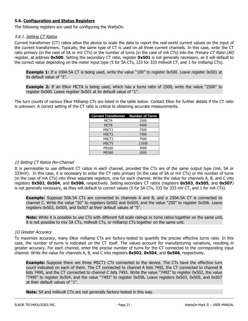
The turn counts of various Elkor Milliamp CTs are listed in the table below. Contact Elkor for further details if the CT ratio is unknown. A correct setting of the CT ratio is critical to obtaining accurate measurements.
Current Transformer Number of Turns
MCTA 2500
MCTB 4000
MSCT1 7500
MSCT2 7500
MSCT3 7500
MSCT5 11000
MS160 3000
MS360 2000
(i) Setting CT Ratios Per-Channel
It is permissible to use different CT ratios in each channel, provided the CTs are of the same output type (mA, 5A or 333mV). In this case, it is necessary to enter the CT ratio primary (in the case of 5A or mV CTs) or the number of turns
(in the case of mA CTs) into three separate registers, one for each channel. Write the value for channels A, B, and C into registers 0x502, 0x504, and 0x506, respectively. Setting secondary CT ratios (registers 0x503, 0x505, and 0x507)
is not generally necessary, as they will default to correct values (5 for 5A CTs, 333 for 333 mV CT, and 1 for mA CTs).
Example: Suppose 50A:5A CTs are connected to channels A and B, and a 250A:5A CT is connected to
channel C. Write the value “50” to registers 0x502 and 0x504, and the value “250” to register 0x506. Leave registers 0x503, 0x505, and 0x507 at their default values of “5”.
Note: While it is possible to use CTs with different full scale ratings or turns ratios together on the same unit,
it is not possible to mix 5A CTs, millivolt CTs, or milliamp CTs together on the same unit.
(ii) Greater Accuracy
To maximize accuracy, many Elkor milliamp CTs are factory-tested to quantify the precise effective turns ratio. In this
case, the number of turns is indicated on the CT itself. The values account for manufacturing variations, resulting in greater accuracy. For each channel, enter the precise number of turns for the CT connected to the corresponding input
channel. Write the value for channels A, B, and C into registers 0x502, 0x504, and 0x506, respectively.
Example: Suppose there are three MSCT1 CTs connected to the device. The CTs have the effective turn
count indicated on each of them. The CT connected to channel A lists 7492, the CT connected to channel B lists 7490, and the CT connected to channel C lists 7493. Write the value “7492” to register 0x502, the value
“7490” to register 0x504, and the value “7493” to register 0x506. Leave registers 0x503, 0x505, and 0x507 at their default values of “1”.
Note: 5A and millivolt CTs are not generally factory-tested in this way.

ELKOR TECHNOLOGIES INC. - Page 22 - WattsOn-Mark II – USER MANUAL
Name
Off
se
t
Ad
dre
ss
Siz
e
Typ
e
R/W
De
fau
lt
Description
Primary CT Ratio (All) 0x500 41281 16 U RW *
Used for setting the CT ratios of each phase. Writing to the “All” registers globally sets the CT ratios for all of the phases simultaneously. If the CT ratios are not identical in all three channels, the “All” values are read as "0". See p. 21.
Secondary CT Ratio (All) 0x501 41282 16 U RW *
Primary CT Ratio A 0x502 41283 16 U RW *
Secondary CT Ratio A 0x503 41284 16 U RW *
Primary CT Ratio B 0x504 41285 16 U RW *
Secondary CT Ratio B 0x505 41286 16 U RW *
Primary CT Ratio C 0x506 41287 16 U RW *
Secondary CT Ratio C 0x507 41288 16 U RW *
Primary PT Ratio (All) 0x508 41289 16 U RW 1
Used for setting the PT ratios for each phase. Writing to the “All” registers globally sets the PT ratios for all of the phases simultaneously. If the PT ratios are not identical in all three channels, the “All” values are read as "0". See p. 23.
Secondary PT Ratio (All) 0x509 41290 16 U RW 1
Primary PT Ratio A 0x50A 41291 16 U RW 1
Secondary PT Ratio A 0x50B 41292 16 U RW 1
Primary PT Ratio B 0x50C 41293 16 U RW 1
Secondary PT Ratio B 0x50D 41294 16 U RW 1
Primary PT Ratio C 0x50E 41295 16 U RW 1
Secondary PT Ratio C 0x50F 41296 16 U RW 1
Debug 16-bit 0x510 41297 16 S R 12345 These registers always output their default values. They are useful for debugging communication with the device.
Debug 32-bit 0x511 41298 32 S R 1234567
Debug Floating-Point 0x513 41300 32 F R 1234.567
Uptime 0x515 41302 32 U RW - Seconds since the device was last powered on or reset. See p. 23.
Masking Enabled 0x517 41304 16 B RW False Indicates whether Modbus Masking is enabled. See p. 23.
Masking Override 0x518 41305 16 B RW False Indicates whether masks can override existing registers. See p. 23.
Noise Filtering Enabled 0x519 41306 16 B RW True Indicates whether low current noise filtering is enabled. See p. 23.
32-bit Little Endian Mode 0x51A 41307 16 B RW False If enabled, 32-bit registers are sent least significant word first. See p. 23.
Current LED Threshold 0x51B 41308 16 S RW 1 (0.1%) Expressed in 10ths of a percent of the full scale (varies by model). See p. 24.
Voltage LED Threshold 0x51C 41309 16 S RW 5 (5%) Expressed as a percentage of 400V. See p. 24.
Serial Number 0x51D 41310 32 U RW - Factory programmed serial number of the unit.
Hardware Version 0x51F 41312 16 U R - Version numbers of different hardware and software components of this device. Divide by 100 to get the version number; for example, a value of “100” indicates version 1.00.
Firmware Version 0x520 41313 16 U R -
Bootloader Version 0x521 41314 16 U R -
Model Number 0x522 41315 16 U RW - The model number of the device. This is expressed as a two-byte ASCII string. 19761 indicates the “M1” model.
Input Configuration 0x523 41316 16 U RW - “1” for milliamp CTs, “2” for mV CTs, “3” for 5A CTs, “0” for a custom setup.
Energy Reset 0x524 41317 16 U RW - Writing 0xA5A5 (42405) resets the accumulated energy to 0. See p. 24.
Compatibility Mode 0x525 41318 16 B RW False Enables limited emulation of the WattsOn-1100's register map. See p. 24.
Power Factor Sign Mode 0x526 41319 16 U RW 3 (Quad) Indicates how the sign of the power factor is calculated. See page 24.
Passcode 0x527 41320 32 U RW - Used for entering a passcode when locking or unlocking the device. See p. 25.
Lock 0x529 41322 16 U RW 0 “0” indicates unlocked, “1” indicates locked. With a passcode entered above, write “0” to unlock, “1” to lock, or “2” to change the passcode. See p. 25.
Phase Compensation (All) 0x52A 41323 16 S RW 0 Compensates for the inherent phase shift in current transformers for more accurate power measurements. Represented in units of 0.01 degrees. Writing to the “All” register sets the phase compensation values for all phases simultaneously. If the values are not identical in all three channels, the “All” register reads as "0". See p. 26.
Phase Compensation A 0x52B 41324 16 S RW 0
Phase Compensation B 0x52C 41325 16 S RW 0
Phase Compensation C 0x52D 41326 16 S RW 0
Energy Integer Divider 0x52E 41327 16 U RW 100 Divisor for integer energy values to allow fitting into 32 bits. See p. 26.
SW Sub-Interval Length 0x52F 41328 16 U RW 60 The length in seconds of a sub-interval for sliding window power. See p. 26.
SW Sub-Interval Count 0x530 41329 16 U RW 15 The number of sub-intervals for sliding window power. See p. 26.
SW Synchronize 0x531 41330 16 U RW - Resets the timer of the sliding window power calculation. See p. 26.
Auto Frequency Channel 0x532 41331 16 B RW True Auto-select a valid voltage channel for frequency measurement. See p. 27.
Frequency Active Channel 0x533 41332 16 U RW 0 (A) Voltage channel used to measure frequency. 0, 1, 2 for A, B, C. See p. 27.
Reserved 0x534 41333 16 - R 0 Reserved for future use. These registers output “0” when read. To ensure compatibility with future versions, these registers should not be written to.
…
Reserved 0x53F 41344 16 - R 0
Scratch Pad Register 1 0x540 41345 16 - RW 0 32 registers available for user storage. Values written here are stored in non-volatile memory. They can be used to store room numbers, customer IDs, etc. They can be used as 32 16-bit registers, or 16 32-bit registers.
…
Scratch Pad Register 32 0x54F 41376 16 - RW 0
* Default values depend on the input type of the device. Milliamp units default to “1”, 333 mV units default to “333”, and 5A units default to “5”. Because the primary and secondary values are equal for all models, the ratios all reduce to 1:1 regardless of the input type, by default.

ELKOR TECHNOLOGIES INC. - Page 23 - WattsOn-Mark II – USER MANUAL
5.6.2. Setting PT Ratios
Potential Transformer (PT) ratios allow the device to scale the data to report the real-world voltage values on the input of the potential transformers.
Because the WattsOn can accept up to 600V line-to-line voltage directly, potential transformers are often not required. In
this case, PT ratios may be left at their default values of 1:1. If potential transformers are being used for higher voltages,
and the same type of transformer is used on all three voltage channels, write the PT ratio primary into the Primary PT Ratio (All) register, at address 0x508 and the PT ratio secondary into the Secondary PT Ratio (All) register, at address
0x509.
Example: If a 600:120V PT is being used (that is, a PT that outputs 120V when the input voltage is 600V), write the value “600” to register 0x508, and the value “120” to register 0x509.
It is also permissible to use different PTs in each channel. In this case, it is necessary to enter the PT ratio primary into three separate registers, one for each channel. Write the value for channels A, B, and C into registers 0x50A, 0x50C,
and 0x50E, respectively. Enter the PT ratio secondary for channels A, B, and C into registers 0x50B, 0x50D, and 0x50F, respectively.
5.6.3. Uptime
The uptime register reports the number of seconds that the device has been running. This counter is reset when the device is powered off, reset, or the bootloader is started. Writes to this register are permitted if desired to represent a
date, time, or elapsed time counter.
5.6.4. Masking
Modbus Masking is a feature used to change the Modbus map of the device. It can be enabled or disabled by writing a “1” or “0”, respectively, to the Modbus Enabled register, 0x517. Custom Modbus blocks may be configured to exist in the
same register address space as the native WattsOn registers; this functionality can be enabled by writing a “1” to the
Masking Override register, 0x518. Otherwise, the WattsOn native registers will always override custom register blocks. See 6, Customizing the Register Map (p. 33) for details on this feature.
5.6.5. Low Current Noise Filtering
When reading very low current values (such as below 1% of the unit’s full scale), noise may become noticeable. Due to
the design of the analog-to-digital converters in the device, there are slight oscillations at low input values, which may
appear as reading instability. A proprietary noise filtering algorithm is employed by default to filter out noise when reading low current values, improving accuracy and increasing the dynamic range of the device. However, this will result in slower
response times for low fluctuating signals. The settling time for slowly changing signals is approximately 5 seconds, however the settling time is much lower (i.e., under 500 ms) for signals that change magnitude quickly.
Note: Energy accumulation accuracy is not affected by this setting.
Filtering may be disabled by writing a “0” to register 0x519 (41306).
5.6.6. Setting 32-bit Endianness
By default, the higher-order 16-bit word of a 32-bit register is the register with the lower Modbus address, and the lower-order word is at the higher address. Most Modbus software and devices will interpret 32-bit registers this way. Writing a
“1” to the 32-bit Little Endian register at address 0x51A (41307) configures the WattsOn to reverse the 16-bit word
ordering, so that the higher-order word is at the higher address, and the lower-order word is at the lower address. See the following table for an example.
For an total active power of 100,000 kW (hexadecimal 0x186A0)
32-bit Little Endian Mode register 0x51A = 0 (default) 32-bit Little Endian Mode register 0x51A = 1
Register Decimal Hexadecimal
Register Decimal Hexadecimal
Active Power Total register 0x100 1 0x0001 Active Power Total register 0x100 34,464 0x86A0
Active Power Total register 0x101 34,464 0x86A0 Active Power Total register 0x101 1 0x0001
ELKOR TECHNOLOGIES INC. - Page 24 - WattsOn-Mark II – USER MANUAL
5.6.7. Setting LED Thresholds
The WattsOn features an LED for each of the three current channels and each of the three voltage channels on the device. These LEDs are off when there is low current or voltage on the corresponding input channel. By default, these
thresholds are less than 0.1% of the unit’s maximum measurement current (200 mA, 333 mV, or 10A, depending on the meter type), or less than 5% of the unit’s maximum voltage (400 V).
These percentages can be changed via Modbus. To change the threshold at which the current LED turns on, write to the Current LED Threshold register at address 0x51B (41308). Valid values are between 0 and 1000, representing 0.0% to
100.0%, respectively. To change the threshold at which the voltage LED turns on, write to the Voltage LED Threshold register at address 0x51C (41309). Valid values are between 0 and 100, representing 0% and 100%, respectively. These
settings apply to all channels.
The current LEDs also indicate direction of power flow and poor power factor; see 2.1.2, Current & Power Indicators (p.
7) for details.
5.6.8. Resetting Accumulated Energy
To reset the resettable accumulated data registers to 0, write the hexadecimal value 0xA5A5 (decimal value 42405) into the Energy Reset register, 0x524. Note that this will not affect that data in the revenue accumulated data registers; they
will continue to hold their former values despite any resets.
5.6.9. WattsOn-1100 Compatibility Mode
By writing a “1” to the Compatibility Mode register, 0x525, the WattsOn-Mark II will emulate a partial register map of the
legacy WattsOn-1100. The 32-bit floating-point registers from 0x300 to 0x376, as well as the configuration registers from 0x080 to 0x09E are emulated while in this mode. The 16-bit integer registers are not emulated. See the
WattsOn-1100 manual for details on these registers. With the exception of the CT ratios, PT ratios, and scratch pad registers, the registers in the WattsOn-1100 configuration block are read-only; other settings must be configured using
the WattsOn-Mark II configuration registers instead.
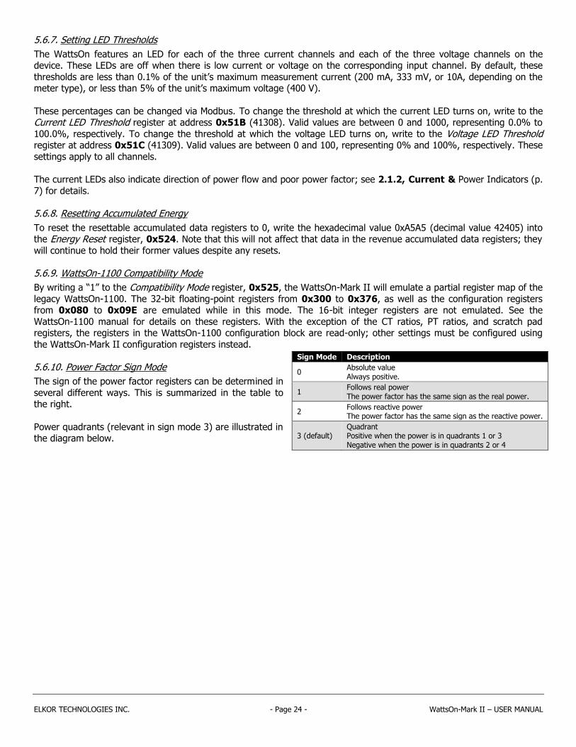
5.6.10. Power Factor Sign Mode
The sign of the power factor registers can be determined in
several different ways. This is summarized in the table to the right.
Power quadrants (relevant in sign mode 3) are illustrated in the diagram below.
Sign Mode Description
0 Absolute value Always positive.
1 Follows real power The power factor has the same sign as the real power.
2 Follows reactive power The power factor has the same sign as the reactive power.
3 (default) Quadrant Positive when the power is in quadrants 1 or 3 Negative when the power is in quadrants 2 or 4

ELKOR TECHNOLOGIES INC. - Page 25 - WattsOn-Mark II – USER MANUAL
5.6.11. Password Protection
The WattsOn-Mark II features a password protection system. The device can be locked
to prevent writes to ALL of its registers, preventing any settings from being changed or
operations (resets, reboots, etc.) to be performed.
(i) Setting a Password
1. Write any 32-bit number except 0 into the Passcode register, 0x527. This number is the password. Whenever a password has been entered, this register will read “1”.
2. Write “2” to the Lock register, 0x529.
3. Write the same password into the Passcode register, 0x527, a second time. 4. Write “1” to the Lock register. A password has now been set, and the device is now locked.
5. Read the Lock register to confirm that it now read “1”, indicating that the device is now locked.
(ii) Unlocking the Device
1. Write the password into the Passcode register, 0x527. This register will read “1”.
2. Write “0” to the Lock register. If the password was correct, the device is now unlocked (the Lock register will read as 0) and the device can be written to normally. If the password was incorrect, the Lock register will
continue to read “1”, and the device will reject all password attempts for the next 5 seconds.
Once the device has been unlocked, it will remain unlocked for 10 minutes, or until the device is either manually locked again or rebooted, whichever comes first. To permanently unlock the device, see (v) Removing Password Protection.
(iii) Locking the Device (if a password has previously been set)
1. Write the password into the Passcode register, 0x527. This register will read “1”.
2. Write “1” to the Lock register. If the password was correct, the device is now locked (the Lock register will read as 1) and the device cannot be written to until unlocked again. If the password was incorrect, the Lock register
will continue to read “0”, and the device will remain unlocked.
3. Read the Lock register to confirm that it reads “1”, indicating that the device is now locked.
Lock Register Operation Value
Unlock 0
Lock/Confirm Passcode 1
Change Passcode 2
θ
0° (+) Active Energy
(Delivered)
(–) Active Energy 180°
(Received)
(+) Reactive
90°
270° (–) Reactive
I Lagging Power Factor
II Leading Power Factor
III Lagging Power Factor
IV Leading Power Factor
ELKOR TECHNOLOGIES INC. - Page 26 - WattsOn-Mark II – USER MANUAL
(iv) Changing the Password
1. If the device is locked (the Lock register, 0x527 reads “1”), unlock the device; see (ii) Unlocking the Device. 2. Write a new password (any 32-bit number except 0) into the Passcode register, 0x527. This register will now
read “1”. 3. Write “2” to the Lock register, 0x529.
4. Write the same password into the Passcode register, 0x527, a second time.
5. Write “1” to the Lock register. The password has now been changed, and the device is now locked. 6. Read the Lock register to confirm that it now reads “1”, indicating that the device is now locked.
(v) Removing Password Protection
1. If the device is locked (the Lock register, 0x527 reads “1”), unlock the device; see (ii) Unlocking the Device.
2. Write “0” into the Passcode register, 0x527. This register will now read “1”. 3. Write “2” to the Lock register, 0x529. The password protection has now been removed.
5.6.12. Phase Compensation
Most current transformers have an inherent phase shift. This causes inaccuracies in power measurements as the power
factor decreases. If the phase shift of a particular type of CT is known, the WattsOn can compensate for this phase shift either globally or per-phase.
Phase compensation values are entered in hundreds of a degree, so a value of 1 represents a 0.01° compensation for lag. Some current transformers have the phase shift value printed on the label.
5.6.13. Energy Integer Divider
It is recommended to read the device using floating-point registers if possible, as floating-point registers can represent
arbitrarily large energy values regardless of the scaling applied.
When using integer accumulated data registers, as described in section 5.5, Accumulated Data Registers (p. 15), only
values between -2,147,483,648 and +2,147,483,647 can be read. In order to permit reading larger energy values, they are first divided by the divider programmed into the Energy Integer Divider register, 0x52E (by default, 100) before they
are returned in these registers. With the default setting, the base resolution of the integer registers is 100 Wh/VAh/VARh.
Depending on the size of the system being monitored, it may be desirable to use a higher divider (if reaching values in
excess of 2 billion is anticipated soon), or a lower divider (for greater resolution). Set this register to 1 to read individual Watt-hours (or VAh/VARh), or 1000 to read kWh (or kVAh/kVARh). Only multiples of 10 from 1 to 10000 may be used.
Floating-point registers do not make use of this register.
Example 1: Suppose the system is consuming 10,000 kW. After 1 hour, the WattsOn will accumulate
10,000,000 Wh of energy. With a default divider of 100, the energy register would read “100,000” at this time. Dividing the maximum value (2,147,483,647) by 100,000 yields about 21,475 hours (2.5 years) before
the energy will no longer fit into a 32-bit register. The divider should be set to a higher value, such as 1,000 to extend to use of these registers, or floating-point may be read instead.
Example 2: Suppose the system is consuming 100 kW. After 1 hour, the WattsOn will accumulate 100,000
Wh of energy. With a default divider of 100, the energy register would read “1,000” at this time. Dividing the
maximum value (2,147,483,647) by 1,000 yields about 2,147,484 hours (250 years) before the energy will no longer fit into a 32-bit register. The divider may be set to a lower value, such as 10 to increase the
resolution of the energy registers from 100 Wh/VAh/VARh to 10 Wh/VAh/VARh.
5.6.14. Sliding Window Demand Power Measurement
The WattsOn can measure the average power over an arbitrary interval of time, called demand power. The interval length
can be programmed in seconds to any value between 1 and 65,535 seconds. Typical values are 1 minute (60 seconds), 5 minutes (300 seconds), 10 minutes (600 seconds), 15 minutes (900 seconds), 30 minutes (1800 seconds), 1 hour (3600
seconds), or any arbitrary value expressed in seconds.

ELKOR TECHNOLOGIES INC. - Page 27 - WattsOn-Mark II – USER MANUAL
In addition, the WattsOn can be configured to measure sliding window (also called rolling demand) power. In this case,
the time interval is divided into several sub-intervals. The average power over the full interval is updated each sub-interval. This device can be configured for up to 60 sub-intervals. The interval length is equal to the sub-interval length
times the number of sub-intervals. If sub-intervals are not needed, set the sub-interval count to 1.
Example 1: To configure the device to record the average power over 15 minute intervals, set the SW Sub-Interval Length register, 0x52F, to 900 (15 minutes × 60 seconds) and the SW Sub-Interval Count register, 0x530, to 1. Every 15 minutes, the Sliding Window Power registers will update with the average power over
the previous 15 minutes.
Example 2: To configure the device to record the average power over 15 minute intervals, updating every 5 minutes, set the SW Sub-Interval Length register, 0x52F, to 300 (5 minutes × 60 seconds) and the SW Sub-Interval Count register, 0x530, to 3 (15 minute intervals ÷ 5 minute sub-intervals). Every five minutes, the
Sliding Window Power registers will update with the average power over the previous 15 minutes.
Writing any value to the SW Sub-Interval Length register, the SW Sub-Interval Count register, or writing a 1 to the SW Synchronize register restarts the demand interval.
5.6.15. Frequency Measurement Channel
Frequency is measured using one of the three voltage channels. By default, the device will automatically select a voltage channel with an RMS voltage greater than 5V on which to perform the frequency measurement. If the voltage in this
channel falls to below 5V, a new channel will be automatically selected. If no channel contains a voltage above this threshold, the frequency will read “0”. The channel currently being used is displayed in the Frequency Active Channel register, 0x533 (0, 1, and 2 represent channels A, B, and C, respectively).
The meter may instead be forced to use a specific voltage channel for frequency measurement. To do so, first disable
automatic channel selection by writing “0” into the Auto Frequency Channel register, 0x532. Then, write a value into the Frequency Active Channel register corresponding to the desired channel to be used for frequency measurement, with “0”
representing channel A (the first channel from the left), “1” representing channel B, and “2” representing channel C.
5.6.16. Scratch Pad Registers
There are 32 scratch pad registers available, starting at register 0x540 and ending at 0x55F. Any values can be written
to these registers. Values written to these registers will be stored in non-volatile memory so that they are retained after the device has been powered off or rebooted. These can be used for room numbers, customer IDs, or any other purpose
as desired. These registers are not used for any measurement purposes.
Note: Consideration should be given to the fact that these registers are written to flash memory, which has
limited write cycle endurance. Writes should be limited to fewer than 10,000 operations. Writes in excess of 10,000 may cause the device to become permanently read-only in order to protect itself from a flash failure.

ELKOR TECHNOLOGIES INC. - Page 28 - WattsOn-Mark II – USER MANUAL
5.7. System Registers
These registers are used to configure the serial communication parameters, to reset the device, or to enter the device’s bootloader mode for firmware updates.
5.7.1. Modbus Addresses above 15
Using the rotary switch, addresses from 1-15 can be set. The switch indicates numbers as hexadecimal values, with 1-9
being shown as normal, A representing 10, B representing 11, and so on. When the rotary switch is set to F (15), the device will instead use an address entered into the Modbus Address register, 0x600, which defaults to 15. This allows
addresses of 16 or greater to be assigned, or allows the address to be configurable conveniently over Modbus. Addresses
up to 247 can be programmed into this register; higher addresses are not allowed under the Modbus specification.
Changes are not applied until a “1” is written to the Serial Commit register. Once the change is applied, a read of any register must be performed using the new Modbus address to confirm the change. See 5.7.3, Confirming Serial
Settings Change (p. 29) for details.
5.7.2. Configuring Serial Parameters
By default, the WattsOn ships pre-configured with the most common serial settings — 9600 baud, no parity, 8 data bits, 1
stop bit. In addition to the default settings, the WattsOn supports a variety of other baud rates, parity modes, and stop bit modes.
Supported serial settings are listed in the table below.
Parameter Default Setting Supported Values
Baud rate 9600 9600, 19200, 28800, 38400, 48000, 57600, 115200, 230400
Parity No Parity (0) No Parity (0), Odd Parity (1), Event Parity (2)
Stop bits 1 1, 2
Settings are changed by writing to the corresponding Modbus registers. To change the baud rate, write the new value to the Serial Baud Rate register 0x601. For baud rates below 115200, write the value as-is into the register. For instance,
to change the baud rate to 57600, write “57600” to register 0x601. For baud rates equal to or greater than 115200, write only the first three digits into the register; this is done because such values are too large to fit into 16-bit registers.
For instance, to change the baud rate to 115200, write “115” to register 0x601. To change the parity mode, write a “0” for no parity, “1” for odd parity, or “2” for even parity into the Serial Parity Mode register 0x602. To change the number
of stop bits, enter “1” for 1 stop bit or “2” for 2 stop bits into the Serial Stop Bits register 0x603.
Name
Off
se
t
Ad
dre
ss
Siz
e
Typ
e
R/W
De
fau
lt
Description
Modbus Address 0x600 41537 16 U RW 15 If the hardware address switch is in the “F” position, the value set here is used instead of the switch’s address. This allows addressing more than 15 Modbus devices on the same line.
Serial Baud Rate 0x601 41538 16 U RW 9600
Sets the device’s serial parameters. These settings are not applied until a “1” is written to the Serial Commit register, and are not permanent until a valid Modbus query message is received using the new settings.
Serial Parity Mode 0x602 41539 16 U RW 0
Serial Stop Bits 0x603 41540 16 U RW 1
Serial Response Delay 0x604 41541 16 U RW 0
Serial Commit 0x605 41542 16 U RW 0
Reserved 0x606 41543 16 - R 0 Reserved for future use. These registers output “0” when read. To ensure compatibility with future versions, these registers should not be written to. Reserved 0x607 41544 16 - R 0
Device Mode 0x608 41545 16 U R 1 “1” indicates the device firmware is running normally, “2” indicates the device is in bootloader mode.
Reset to Firmware 0x609 41546 16 U W 0 Write the value 0xAA55 (43605) to reboot the unit. This register always reads as “0”.
Reset to Bootloader 0x60A 41547 16 U W 0 Write the value 0xB001 (45057) to reboot the unit. When reset in this way, the device will enter bootloader mode. This register always reads as “0”.

ELKOR TECHNOLOGIES INC. - Page 29 - WattsOn-Mark II – USER MANUAL
In cases where legacy Modbus master devices cannot process responses fast enough, it may be necessary to enable a
response delay within the WattsOn. If such problems exist, a delay may be introduced by using the Serial Response Delay register 0x604. The WattsOn will wait at least as long as specified by this register (in milliseconds) before
responding. Generally, small values between 0 to 100 milliseconds are sufficient. The default value is “0”, meaning that the WattsOn will respond as soon as its data is ready to reply to the query.
Changes are not applied until a “1” is written to the Serial Commit register. This is to ensure that all serial settings are applied at once, in case that more than one serial parameter was changed. Once the changes are applied, the new
settings must be confirmed by reading any register using the new settings, as described in the section below.
5.7.3. Confirming Serial Settings Change
In order to guard against accidental changes to the device’s serial settings and to protect against incorrect or unknown values, there is a 3-minute period in which the Modbus master device must successfully communicate with the WattsOn
before the new settings become permanent. This is to ensure that the Modbus master software or device is capable of
correctly communicating at the new settings. Reading or writing any register, or using any other Modbus function, is sufficient for this purpose. If a successful query is not received within the 3-minute waiting period, or the WattsOn was
rebooted before a successful communication, the previous settings will be restored.
As an additional failsafe, when the WattsOn’s Modbus address is set to address 0 via the rotary switch on the unit, it will
always communicate using default serial settings (9600 baud, no parity, 1 stop bit). While set to address 0, the device responds to Modbus queries addressed to any Modbus address. The device may then be reconfigured to the appropriate
serial settings. Note that once the WattsOn’s serial settings are changed, the Modbus address must be set to a non-zero value before it will begin using the new settings, so that the new settings can be confirmed as described in the paragraph
above. New serial settings cannot be confirmed while in address 0.
5.7.4. Changing Settings from a Known Configuration
A step-by-step procedure for changing the serial configuration from a known configuration is described below. Use this
procedure if communications with the device is established, but changes to the Modbus settings are required. This procedure does not require physical access to the device (it can be done from a remote location).
1. Change the desired serial parameters by writing to the corresponding Modbus registers.
2. Write a “1” to the Serial Commit register 0x605
3. Change the Modbus master device’s serial settings to match the settings applied to the WattsOn. 4. Read any register from the WattsOn using the new serial settings within 3 minutes to make the change
permanent. Note that the WattsOn should remain powered during this time, or its settings will revert to their previous values.
Note: If the settings do not work with the Modbus master device, or if a mistake was made, wait 3 minutes or power cycle the device, and the previous settings will be restored.
5.7.5. Changing Settings from an Unknown Configuration
A step-by-step procedure for changing the serial settings from an unknown configuration is described below. Use this
procedure if the device settings are not known, and communication is not possible. This procedure requires physical access to the device.
1. Set the device’s Modbus address to 0 using the hardware rotary switch on the device. This sets the device’s serial settings to their factory defaults.
Note 1: In address 0, the WattsOn responds to queries sent from any address. This may include queries
intended for other devices on the Modbus line. It is therefore recommended that any other devices be
removed from the Modbus line when performing this procedure.
Note 2: If the device is powered on while its address is already set to 0, it will enter bootloader mode. The serial settings can be changed in either mode, but the device must be rebooted with a non-zero address
once the procedure is complete in order to read the data registers.
2. Set the Modbus master device’s serial settings to 9600 baud, no parity, 8 data bits, and 1 stop bit.

ELKOR TECHNOLOGIES INC. - Page 30 - WattsOn-Mark II – USER MANUAL
3. Set the serial parameters to the desired values by writing to the corresponding Modbus registers.
4. Write a “1” to the Serial Commit register 0x605 5. Set the device’s Modbus address to 1 (or any non-zero value).
6. Set the Modbus master device to communicate with the WattsOn at the address and serial settings from step 3. 7. Read any register from the WattsOn using the new settings within 3 minutes to make the change permanent.
Note that the WattsOn should remain powered during this time, or its settings will revert to their previous values.

ELKOR TECHNOLOGIES INC. - Page 31 - WattsOn-Mark II – USER MANUAL
5.8. Relay Output Configuration Registers
The WattsOn has two highly configurable relay outputs. These relays can be configured for pulse output, alarm output, or status output. They are configured using the following Modbus register block.
Name O
ffse
t
Ad
dre
ss
Siz
e
Typ
e
R/W
De
fau
lt
Description
Relay K1 Register Offset 0x900 42305 16 U RW 0x1000 Offset of an integer data register to control the output. Floating-point registers cannot be used.
Relay K1 Trigger Type 0x901 42306 16 U RW 0 (Relative)
Indicates whether the output is based on the relative value of the register (i.e., for pulses), or the absolute value of the register (i.e., for alarming).
Relay K1 Upper Bound 0x902 42307 32 S RW 1 Trigger the output when the value (either relative or absolute) goes above this value.
Relay K1 Lower Bound 0x904 42309 32 S RW 0 Trigger the output when the value (either relative or absolute) goes below this value.
Relay K1 Min Duration 0x906 42311 16 U RW 100
Minimum duration that the output is triggered, in milliseconds. If the Trigger Type is set to “0” (Relative), this is the duration of the pulse. If it is set to “1” (Absolute), the relay will remain triggered for at least this long, even if the threshold is crossed for a shorter period of time. To hold indefinitely, enter the maximum value “65535” (hexadecimal 0xFFFF) – this will hold the event until any register in this block is written.
Relay K1 Active Mode 0x907 42312 16 U RW 0 (N.O.) "0" indicates that the output is normally open, "1" indicates that it is normally closed, and "2" indicates that the output toggles each time it is triggered.
Reserved 0x908 42313 16 - R 0 Reserved for future use. These registers output “0” when read. To ensure compatibility with future versions, these registers should not be written to. Reserved 0x909 42314 16 - R 0
Relay K2 Register Offset 0x90A 42315 16 U RW 0x1002 Offset of an integer data register to control the output. Floating-point registers cannot be used.
Relay K2 Trigger Type 0x90B 42316 16 U RW 0 (Relative)
Indicates whether the output is based on the relative value of the register (i.e., for pulses), or the absolute value of the register (i.e., for alarming).
Relay K2 Upper Bound 0x90C 42317 32 S RW 1 Trigger the output when the value (either relative or absolute) goes above this value.
Relay K2 Lower Bound 0x90E 42319 32 S RW 0 Trigger the output when the value (either relative or absolute) goes below this value.
Relay K2 Min Duration 0x910 42321 16 U RW 100
Minimum duration that the output is triggered, in milliseconds. If the Trigger Type is set to “0” (Relative), this is the duration of the pulse. If it is set to “1” (Absolute), the relay will remain triggered for at least this long, even if the threshold is crossed for a shorter period of time. To hold indefinitely, enter the maximum value “65535” (hexadecimal 0xFFFF) – this will hold the event until any register in this block is written.
Relay K2 Active Mode 0x911 42322 16 U RW 0 (N.O.) "0" indicates that the output is normally open, "1" indicates that it is normally closed, and "2" indicates that the output toggles each time it is triggered.
Common configurations of the relay outputs are described below.
5.8.1. Configuring a Pulse Output
The relay outputs may be configured to pulse upon accumulation of a specified quantity of energy. To do so, follow the steps below.
1. Select which energy register to use for pulses, such as the Net Total Energy register, at address 0x1000, or
another register from the list of Resettable Integer Accumulated Data Registers (p. 17) or Revenue
(Non-Resettable) Integer Accumulated Data Registers (p. 19). Enter the register offset into the Relay K1 Register Offset register, 0x900, to pulse on the relay output labelled K1 on the device, or into the Relay K2 Register Offset register, 0x90A, to pulse on the relay output labelled K2 on the device.
2. Write “0” into the Relay K1/K2 Register Offset register, 0x901/0x902 to indicate relative mode. This causes the
pulses to trigger when the register value changes, rather than on a set value.
3. To pulse on positive energy accumulation (consumption), enter a value into the Relay K1/K2 Upper Bound register, 0x902/0x90C. By default, with the Energy Integer Divider register set to 100, the energy accumulation
registers increase by 1 for each 100 Wh/VAh/VARh of energy. Therefore, enter “1” to pulse on every 100

ELKOR TECHNOLOGIES INC. - Page 32 - WattsOn-Mark II – USER MANUAL
Wh/VAh/VARh of energy accumulated, “10” for every 1.0 kWh/kVAh/kVARh, etc. To only pulse on negative
energy accumulation (generation), write a “0” into this register. 4. To pulse on negative energy accumulation (generation), enter a value into the Relay K1/K2 Lower Bound
register, 0x904/0x90E. As above, by default, a value of “1” represents 0.1 Wh/VAh/VARh. Write “0” to ignore negative energy accumulation.
5. Enter the desired duration of the pulse in milliseconds into the Relay K1/K2 Min Duration register, 0x906/0x910.
For example, enter “100” for 100 millisecond pulses, or 1000 for 1 second pulses. 6. To have the relay close when a pulse is generated (normally open), enter a “0” into the Relay K1/K2 Active Mode
register, 0x907/0x911. To have the relay open when a pulse is generated (normally closed), enter a “1” into that register. To have the relay toggle between being opened and closed with each pulse, enter a “2” into that
register.
5.8.2. Configuring a Threshold/Alarm Output
The relay outputs may be configured to open or close when a register raises above or falls below a certain threshold. To
do so, follow the steps below. Instantaneous data registers, accumulated data registers, or configuration registers may be used.
1. Select which register to use for alarming from the list of Integer Instantaneous Data Registers (p. 14). Enter the
register offset into the Relay K1 Register Offset register, 0x900, to trigger on the relay output labelled K1 on the
device, or into the Relay K2 Register Offset register, 0x90A, to trigger on the relay output labelled K2 on the device. Note the scaling factor of that register from the register table.
2. Write a “1” into the Relay K1/K2 Register Offset register, 0x901/0x902 to indicate absolute mode. This causes the relay to trigger above or below set values, rather than on relative changes.
3. To trigger the output when the parameter rises above a threshold value, enter a threshold value into the Relay K1/K2 Upper Bound register, 0x902/0x90C. The threshold value should be scaled to match the scaling factor of
the register selected in step 1. To only trigger the output when the value falls below a certain threshold, write
“2,147,483,647” (hexadecimal 0x7FFFFFFF) into this register to disable the high threshold.
Example: To activate the relay whenever the Voltage A value rises above 130V, enter the value 13000 (the Voltage A register has a scaling factor of 100).
4. To trigger the output when the parameter falls below a threshold value, enter a threshold value into the Relay K1/K2 Lower Bound register, 0x904/0x90E. The threshold value should be scaled to match the scaling factor of
the register selected in step 1. To only trigger the output when the value rises above a certain threshold, write “-2,147,483,648” (hexadecimal 0x80000000) into this register to disable the low threshold.
Example: To activate the relay whenever Voltage A value falls below 90V, enter the value 9000 (the Voltage A register has a scaling factor of 100).
5. Enter the desired minimum duration of trigger in milliseconds into the Relay K1/K2 Min Duration register,
0x906/0x910. For example, to ensure that the output is triggered for at least 1 second, enter “1000” into that register. “0” can be used if no minimum duration is required; in that case, the alarm output will follow the
duration of the event. Note that most registers are updated once every 500 milliseconds. To hold the alarm
indefinitely, enter the maximum value of 65535 (hexadecimal 0xFFFF); in this case, the alarm can be manually cleared by writing to any register in this register block, such as writing 65535 to this register again.
6. To have the relay close when the parameter is over/under the specified thresholds (normally open), enter a “0” into the Relay K1/K2 Active Mode register, 0x907/0x911. To have the relay open when the parameter is
over/under the specified thresholds (normally closed), enter a “1” into the register. To have the relay alternate
between being opened and closed each time the parameter crosses a threshold, enter a “2” into the register.

ELKOR TECHNOLOGIES INC. - Page 33 - WattsOn-Mark II – USER MANUAL
6. CUSTOMIZING THE REGISTER MAP The addresses of each register in the WattsOn may be customized to obtain compatibility with other devices. This is done
using up to 4 customizable register blocks which can contain any register and may be placed at any address.
Each customizable register block may contain up to 126 registers. The first register in each block is placed at a customizable address, and each subsequent register follows it at consecutive addresses.
This feature is disabled by default. To enable this feature, write “1” to the Masking Enabled register, 0x517, in the
Configuration and Status Registers (p. 21); By default, custom register blocks cannot be placed in the same locations as
existing registers, as doing so complicates troubleshooting. To allow placing custom register blocks in the same locations as existing registers, write “1” to the Masking Override register, 0x518.
To create a custom block, write the block’s starting address to Address register, 0x1500 (for the first block, or 0x1600,
0x1700, or 0x1800, for the second, third, and fourth blocks, respectively). Next, write the number of registers that the
block will contain to the Size register, 0x1501 (or 0x1601, 0x1701, or 0x1801 for the second, third, and fourth blocks, respectively). Finally, write the Modbus address of each register that will be included in the block at addresses from
0x1502 to 0x157F (or from 0x1602, 0x1702, or 0x1802 for the second, third, and fourth blocks, respectively).
Note: To include 32-bit registers, the two consecutive offsets will need to be written (for the higher and lower order register).
Example: To place the Net Total Energy and Firmware Version registers in a custom block starting at offset 0x400, enter “0x400” into start address register 0x1500. Total Energy Consumption is 32-bits long, so it
occupies 2 registers, while Firmware Version is 16-bit, occupying 1 register, for a total of 3 registers occupied in total. Enter “3” into block size register 0x1501.
Enter the values “0x1100”, “0x1101”, and “0x520” into the registers 0x1502 to 0x1504. Because Net Total Energy is 32-bit, both “0x1100” and “0x1101” must be entered.
Setting the Size register to 0 will remove a custom Modbus block. In the event that a custom Modbus block is in the same
location as the Masking Enabled or Masking Override registers, custom Modbus blocks can be removed by writing a “0” to
each of the size registers, 0x1501, 0x1601, 0x1701, and 0x1801.
Custom Register Map Block 1
Name
Off
se
t
Ad
dre
ss
Siz
e
Typ
e
R/W
De
fau
lt
Description
Custom Block 1 Address 0x1500 45377 16 U RW 0 Modbus offset at which the 1st custom Modbus block will be placed.
Custom Block 1 Size 0x1501 45378 16 U RW 0 Number of registers in the 1st custom Modbus block.
Custom Block 1 Register 1 0x1502 45379 16 U RW 0
List of register offsets of the registers that will be included in the 1st custom Modbus block. Register addresses beyond the count specified in the Size register will be ignored.
Custom Block 1 Register 2 0x1503 45380 16 U RW 0
…
Custom Block 1 Register 126 0x157F 45504 16 U RW 0

ELKOR TECHNOLOGIES INC. - Page 34 - WattsOn-Mark II – USER MANUAL
Custom Register Map Block 2
Name
Off
se
t
Ad
dre
ss
Siz
e
Typ
e
R/W
De
fau
lt
Description
Custom Block 2 Address 0x1600 45633 16 U RW 0 Modbus offset at which the 2nd custom Modbus block will be placed.
Custom Block 2 Size 0x1601 45634 16 U RW 0 Number of registers in the 2nd custom Modbus block.
Custom Block 2 Register 1 0x1602 45635 16 U RW 0
List of register offsets of the registers that will be included in the 2nd custom Modbus block. Register addresses beyond the count specified in the Size register will be ignored.
Custom Block 2 Register 2 0x1603 45636 16 U RW 0
…
Custom Block 2 Register 126 0x167F 45760 16 U RW 0
Custom Register Map Block 3
Custom Register Map Block 4
Name
Off
se
t
Ad
dre
ss
Siz
e
Typ
e
R/W
De
fau
lt
Description
Custom Block 3 Address 0x1700 45889 16 U RW 0 Modbus offset at which the 3rd custom Modbus block will be placed.
Custom Block 3 Size 0x1701 45890 16 U RW 0 Number of registers in the 3rd custom Modbus block.
Custom Block 3 Register 1 0x1702 45891 16 U RW 0
List of register offsets of the registers that will be included in the 3rd custom Modbus block. Register addresses beyond the count specified in the Size register will be ignored.
Custom Block 3 Register 2 0x1703 45892 16 U RW 0
…
Custom Block 3 Register 126 0x177F 46016 16 U RW 0
Name
Off
se
t
Ad
dre
ss
Siz
e
Typ
e
R/W
De
fau
lt
Description
Custom Block 4 Address 0x1800 46145 16 U RW 0 Modbus offset at which the 4th custom Modbus block will be placed.
Custom Block 4 Size 0x1801 46146 16 U RW 0 Number of registers in the 4th custom Modbus block.
Custom Block 4 Register 1 0x1802 46147 16 U RW 0
List of register offsets of the registers that will be included in the 4th custom Modbus block. Register addresses beyond the count specified in the Size register will be ignored.
Custom Block 4 Register 2 0x1803 46148 16 U RW 0
…
Custom Block 4 Register 126 0x187F 46272 16 U RW 0

ELKOR TECHNOLOGIES INC. - Page 35 - WattsOn-Mark II – USER MANUAL
7. FIRMWARE UPDATES AND THE BOOTLOADER The WattsOn device contains a bootloader, a small program used to update the device’s firmware. While running in
bootloader mode, the device supports only the System registers listed in section 5.7 for adjusting Modbus settings and rebooting the device.
The device enters bootloader mode under three conditions:
The value “0xB001” is written to the Reset to Bootloader register at address 0x60A.
The device is restarted with its Modbus address DIP switch set to 0.
The device’s firmware is corrupt, possibly due to a failed attempt to update the firmware.
While in bootloader mode, the device’s status LED periodically flashes twice. If the device’s firmware is corrupt, the LED
flashes red, otherwise it flashes green. See section 2.1.1, Status Indicator Codes (p. 7) for details.
To exit bootloader mode, ensure the Modbus address DIP switch is not set to 0, and either power cycle the unit, or write
the value “0xAA55” to the Reset to Firmware register at address 0x609. If the device’s firmware is corrupt, new firmware must be uploaded to the device before it can leave bootloader mode.
If communications is done via a PC, Elkor’s software may be used to update the device firmware. Please contact Elkor for details on the firmware update protocol if required.

ELKOR TECHNOLOGIES INC. - Page 36 - WattsOn-Mark II – USER MANUAL
8. APPENDIX A, WIRING DIAGRAMS
8.1. Four-Wire (Wye) Wiring Diagram
A
B
C
N
LOAD
H1
H1
H1
Interfacing Block (Optional)Including "Dead-Front" FuseBlock and CT Shorting TermainlsSee: Elkor's i-Block
(4 WIRE SYSTEM)
Output Signals to DDC / PLCor Energy Management Systems
12-30Vac/dcPower Supply
+ -
!! DO NOT Ground or interconnect mV/mA CTs
VA VB VC N IA1 IA2 IB1 IB2 IC1 IC2
POWER
MODBUSADDRESS RELAY K1 RELAY K2 X.BUS RS-485
048
12
-+ D+ D- G D+ D-S
TA
TU
S
MB
K1
XB
K2
V
I
A CB
The wiring shown is applicable for all CT types.
In the case of 5A CTs, additional grounding may be required as per local electrical codes.
mV and mA CTs must NOT be grounded or interconnected in any way.
Each CT wire pair, must be terminated at the corresponding input terminals. mV and mA CTs must not be used to feed multiple equipment.
mV and Elkor's mA CTs do not require the use of a shorting mechanism. Their outputs are low energy, voltage limited.
CT Orientation (on the conductor), CT Polarity (into the meter) and CT phasing (relationship to voltage phase) MUST be
observed for correct meter operation.
System voltage and CT insulation class (typically 600V) must be observed.

ELKOR TECHNOLOGIES INC. - Page 37 - WattsOn-Mark II – USER MANUAL
8.2. Three-Wire (Delta) Wiring Diagram (Three CTs)
A
B
C
LOADSOURCE
H1
H1
H1
Interfacing Block (Optional)Including "Dead-Front" FuseBlock and CT Shorting TermainlsSee: Elkor's i-Block
(3 WIRE SYSTEM)
Output Signals to DDC / PLCor Energy Management Systems
12-30Vac/dcPower Supply
+ -
!! DO NOT Ground or interconnect mV/mA CTs
VA VB VC N IA1 IA2 IB1 IB2 IC1 IC2
POWER
MODBUSADDRESS RELAY K1 RELAY K2 X.BUS RS-485
048
12
-+ D+ D- G D+ D-
STA
TU
S
MB
K1
XB
K2
V
I
A CB
The wiring shown is applicable for all CT types.
In the case of 5A CTs, additional grounding may be required as per local electrical codes.
mV and mA CTs must NOT be grounded or interconnected in any way.
Each CT wire pair, must be terminated at the corresponding input terminals. mV and mA CTs must not be used to feed multiple equipment.
mV and Elkor's mA CTs do not require the use of a shorting mechanism. Their outputs are low energy, voltage limited.
CT Orientation (on the conductor), CT Polarity (into the meter) and CT phasing (relationship to voltage phase) MUST be observed for correct meter operation.
System voltage and CT insulation class (typically 600V) must be observed.

ELKOR TECHNOLOGIES INC. - Page 38 - WattsOn-Mark II – USER MANUAL
8.3. Three-Wire (Delta) Wiring Diagram (Two CTs)
NOTE: This wiring method may only be used with the 5A input versions
A
B
CLOADSOURCE
H1
H1
Interfacing Block (Optional)Including "Dead-Front" FuseBlock and CT Shorting TermainlsSee: Elkor's i-Block
(3 WIRE SYSTEM)
Output Signals to DDC / PLCor Energy Management Systems
12-30Vac/dcPower Supply
+ -
VA VB VC N IA1 IA2 IB1 IB2 IC1 IC2
POWER
MODBUSADDRESS RELAY K1 RELAY K2 X.BUS RS-485
048
12
-+ D+ D- G D+ D-S
TA
TU
S
MB
K1
XB
K2
V
I
A CB
WARNING: This wiring method works only with 5A meters/CTs. When using mV or mA CTs,
the 3 wire, 3 CT method must be used (see section 3.9)
In this configuration, additional grounding may be required as per local electrical codes.
CT Orientation (on the conductor), CT Polarity (into the meter) and CT phasing (relationship to voltage phase) MUST be
observed for correct meter operation.
System voltage and CT insulation class (typically 600V) must be observed.

ELKOR TECHNOLOGIES INC. - Page 39 - WattsOn-Mark II – USER MANUAL
8.4. Split-Phase Wiring Diagram
L1
L2
N
LOADSOURCE
H1
H1
Interfacing Block (Optional)Including "Dead-Front" FuseBlock and CT Shorting TermainlsSee: Elkor's i-Block
(3 WIRE SYSTEM)
Output Signals to DDC / PLCor Energy Management Systems
12-30Vac/dcPower Supply
+ -
!! DO NOT Ground or interconnect mV/mA CTs
VA VB VC N IA1 IA2 IB1 IB2 IC1 IC2
POWER
MODBUSADDRESS RELAY K1 RELAY K2 X.BUS RS-485
048
12
-+ D+ D- G D+ D-
STA
TU
S
MB
K1
XB
K2
V
I
A CB
The wiring shown is applicable for all CT types.
In the case of 5A CTs, additional grounding may be required as per local electrical codes.
mV and mA CTs must NOT be grounded or interconnected in any way. Each CT wire pair, must be terminated at the corresponding input terminals.
mV and mA CTs must not be used to feed multiple equipment.
mV and Elkor's mA CTs do not require the use of a shorting mechanism. Their outputs are low energy, voltage limited.
CT Orientation (on the conductor), CT Polarity (into the meter) and CT phasing (relationship to voltage phase) MUST be
observed for correct meter operation.
System voltage and CT insulation class (typically 600V) must be observed.

ELKOR TECHNOLOGIES INC. - Page 40 - WattsOn-Mark II – USER MANUAL
8.5. CT Wiring Notes
Note: Usually, CTs are marked as shown above, where the ‘H1’ indicates the primary current input and ‘X1’ the corresponding secondary current terminal (or lead).
While specifying CTs, one should consider both the electrical and mechanical parameters such as primary wire
size, mounting arrangement, insulation level, the expected load current and accuracy requirements.
If the load is unknown, the bus rating, or better still, the transformer size may be used for the maximum current
calculations. CTs can tolerate large over-correct conditions without damage and the WattsOn can accept a 20%
continuous input overload.
5A CTs are designed to operate with their secondary winding in permanent short, or very close to the short
condition. The 5A WattsOn models provide 0.05Ω burden. If the secondary winding is open while a primary
current is present, high voltage will be generated on the output. This voltage may create a hazard to the
personnel and in some situations it may damage the CT insulation. Provisions should be made to short the secondary winding before any re-wiring is performed. We recommend using a metering Test Switch or CT
Shunting Blocks to be wired between 5A CTs/PTs and WattsOn meter (ie: Elkor i-BlockTM).
mV and Elkor’s mA CTs feature voltage limited outputs, and shorting mechanisms may be omitted.
Grounding may be required for 5A CTs only. 5A WattsOn models have isolated current inputs and 5A CT
grounding is permissible. For two element systems (3 wires), grounding of CTs and PTs should be carefully
observed.
For mV and mA meter models, CTs must not be grounded, or interconnected with each other or any device.
Each CT wire pair must be terminated at the corresponding meter current inputs.
CT Orientation (on the conductor), CT Polarity (into the meter) and CT phasing (relationship to voltage phase) MUST be observed for correct meter operation.

ELKOR TECHNOLOGIES INC. - Page 41 - WattsOn-Mark II – USER MANUAL
9. APPENDIX B, MODBUS PROTOCOL DETAILS Modbus RTU is a protocol used to read and write information from a variety of devices such as the WattsOn. Generally,
the details of the protocol are handled by the Modbus master software or device, so that the user need not be familiar with their implementation. For full details regarding the Modbus protocol, see the official Modbus specification available
for free from http://www.modbus.org/specs.php. This section summaries the Modbus RTU protocol as it pertains to the WattsOn device.
9.1. Modbus Frames
Modbus messages are represented as frames of no more than 256 bytes each. The start of a frame is defined as no
transmissions for at least 3.5 character periods, followed by the Modbus address (a one-byte number between 1 and 247)
and the Modbus function code (a one-byte number). The contents of the frame vary between different function codes. At the end of the frame, comes a 2-byte checksum value used to verify that the frame was not corrupted during reception.
Fields of 2 bytes or more, including the checksum, are transmitted with the most-significant byte first (big-endian order).
The Modbus master device sends “request” messages to a slave device, which responds with a “response” message. Both
request and response messages share the same basic format:
Start Modbus Address
Function Code
Frame Contents CRC
3.5 character times (1 byte) (1 byte) (up to 252 bytes) (2 bytes)
Start: No transmission for 3.5 character times. This is about 3.65 milliseconds with default serial settings.
Example: At a baud rate of 9600 bits per second, with one stop bit, one character requires 10 bits to transmit (one start bit, eight data bits, and one stop bit). Each bit takes 1/9600 seconds to transmit.
Transmitting 3.5 characters of 10 bits each, therefore, takes 35/9600 seconds, or about 3.65 milliseconds.
Modbus Address: This should match the address indicated on the hardware address switch, or match the software-
configured value if the switch is set to “F”. Function Code: Available function codes are described in subsequent sections.
Frame Contents: Varies with the function code, as described in subsequent sections. CRC: Modbus 16-bit cyclic redundancy checksum. This value is described in the following section.
9.2. Cyclic Redundancy Checksum
Each Modbus frame ends in a cyclic redundancy checksum. This is computed from the other bytes in the message when
transmitting the message. When the message is received, the checksum is computed again, and checked against the
checksum found in the message. If the results differ, the message was corrupted during transmission. Below is a simple algorithm for calculating the CRC value, shown in pseudo-code. The variable d[i] is defined as the ith byte of the message,
and the variable size denotes the number of bytes in the message. The result of each bit of a XOR (exclusive or) operation is 0 if the corresponding bits of each input are the same, or 1 if the corresponding bits of each input are
different.
crc ← 0xFFFF loop i from 0 to size - 1 crc ← crc XOR d[i] loop j from 0 to 7 lsb ← crc AND 0x0001 crc ← crc LEFT-SHIFT 1 if lsb = 1 then crc ← crc XOR 0xA001

ELKOR TECHNOLOGIES INC. - Page 42 - WattsOn-Mark II – USER MANUAL
9.3. Read Holding Registers
This is the basic command used to read information from the device. The structure of its frames is as follows.
Request:
Modbus Address
Function Code
Starting Address Register Count CRC
1-63 3 0-65535 1-125 (CRC)
(1 byte) (1 byte) (2 bytes) (2 bytes) (2 bytes)
Response:
Modbus Address
Function Code
Byte Count
First Value
…
CRC
1-63 3 2-250 Hi-byte Lo-byte (CRC)
(1 byte) (1 byte) (1 byte) (2 bytes) (2 bytes)
9.4. Read Input Registers
On this device, this command is identical to Read Holding Registers, above, but uses function code 4 instead of 3.
9.5. Write Single Register
This is the basic command used to write data to a single configuration register. The structure of its frames is as follows:
Request:
Modbus Address
Function Code
Address Value CRC
1-63 6 0-65535 Hi-byte Lo-byte (CRC)
(1 byte) (1 byte) (2 bytes) (2 bytes) (2 bytes)
Response (identical to the response):
Modbus Address
Function Code
Address Value CRC
1-63 6 0-65535 Hi-byte Lo-byte (CRC)
(1 byte) (1 byte) (2 bytes) (2 bytes) (2 bytes)
9.6. Write Multiple Registers
This command writes data to multiple configuration registers. The structure of its frames is as follows:
Request:
Modbus Address
Function Code
Starting Address Register Count Byte Count
First Value
…
CRC
1-63 16 0-65535 1-123 2-246 Hi-byte Lo-byte (CRC)
(1 byte) (1 byte) (2 bytes) (2 bytes) (1 byte) (2 bytes) (2 bytes)
Response:
Modbus Address
Function Code
Starting Address Register Count CRC
1-63 16 0-65535 1-123 (CRC)
(1 byte) (1 byte) (2 bytes) (2 bytes) (2 bytes)

ELKOR TECHNOLOGIES INC. - Page 43 - WattsOn-Mark II – USER MANUAL
9.7. Mask Write Register
This command is used to modify bits in an individual register, based on an AND mask and an OR mask. The register is
written to based on the result of the following expression:
Result = (Current Contents AND AndMask) OR (OrMask AND (NOT AndMask))
Example 1: To clear the 1st bit of a register to 0, use an AND mask of 0xFFFE and an OR mask of 0x0000.
Example 2: To set the 1st bit of a register to 1, use an AND mask of 0xFFFE and an OR mask of 0x0001. Example 3: To AND the value of a register with 0x5555, use an AND mask of 0x5555 and an OR mask of 0.
The structure of its frames is as follows:
Request:
Modbus Address
Function Code
Address And Mask Or Mask CRC
1-63 22 0-65535 Hi-byte Lo-byte Hi-byte Lo-byte (CRC)
(1 byte) (1 byte) (2 bytes) (2 bytes) (2 bytes) (2 bytes)
Response (identical to the request):
Modbus Address
Function Code
Address And Mask Or Mask CRC
1-63 22 0-65535 Hi-byte Lo-byte Hi-byte Lo-byte (CRC)
(1 byte) (1 byte) (2 bytes) (2 bytes) (2 bytes) (2 bytes)
9.8. Read/Write Multiple Registers
This function performs reads and writes in a single command. The writes occur before the reads. The structure of its
frames is as follows:
Request:
Modbus Address
Function Code
Read Starting Address
Read Count
Write Starting Address
Write Count Write Byte
Count
First Value
…
CRC
1-63 23 0-65535 1-125 0-65535 1-121 2-246 Hi-byte Lo-byte (CRC)
(1 byte) (1 byte) (2 bytes) (2 bytes) (2 bytes) (2 bytes) (1 byte) (2 bytes) (2 bytes)
Response:
Modbus Address
Function Code
Byte Count
First Value
…
CRC
1-63 23 2-250 Hi-byte Lo-byte (CRC)
(1 byte) (1 byte) (1 byte) (2 bytes) (2 bytes)
Note: The response format for Read/Write Multiple Registers is identical to that of Read Holding Registers,
aside from the function code.

ELKOR TECHNOLOGIES INC. - Page 44 - WattsOn-Mark II – USER MANUAL
9.9. Diagnostic Functions
This function contains a series of sub-functions used to perform diagnostic operations on the device and the
communication line. The sub-functions are described below.
9.9.1. Echo Query Data
This function simply returns the data sent to it, for testing purposes.
Request:
Modbus Address
Function Code
Sub-function Code
Data CRC
1-63 8 0 Any value (CRC)
(1 byte) (1 byte) (1 bytes) (2 bytes) (2 bytes)
Response (identical to the request):
Modbus Address
Function Code
Sub-function Code
Data CRC
1-63 8 0 The sent value (CRC)
(1 byte) (1 byte) (1 bytes) (2 bytes) (2 bytes)
9.9.2. Clear Counters
This function clears the device’s count of all messages, slave messages, communication errors, and exceptions since
power-up.
Request:
Modbus Address
Function Code
Sub-function Code
Data (always 0) CRC
1-63 8 10 0 (CRC)
(1 byte) (1 byte) (1 bytes) (2 bytes) (2 bytes)
Response (identical to the request):
Modbus Address
Function Code
Sub-function Code
Data (always 0) CRC
1-63 8 10 0 (CRC)
(1 byte) (1 byte) (1 bytes) (2 bytes) (2 bytes)
9.9.3. Return Bus Message Count
This function returns a count of all Modbus message this device has seen on the bus since power-up, regardless of
whether they were addressed to this device or another device on the line.
Request:
Modbus Address
Function Code
Sub-function Code
Data (always 0) CRC
1-63 8 11 0 (CRC)
(1 byte) (1 byte) (1 bytes) (2 bytes) (2 bytes)
Response:
Modbus Address
Function Code
Sub-function Code
Data CRC
1-63 8 11 Counter value (CRC)
(1 byte) (1 byte) (1 bytes) (2 bytes) (2 bytes)

ELKOR TECHNOLOGIES INC. - Page 45 - WattsOn-Mark II – USER MANUAL
9.9.4. Return Slave Message Count
This function returns a count of all Modbus messages addressed to this device that it has received since power-up.
Request:
Modbus Address
Function Code
Sub-function Code
Data (always 0) CRC
1-63 8 14 0 (CRC)
(1 byte) (1 byte) (1 bytes) (2 bytes) (2 bytes)
Response:
Modbus Address
Function Code
Sub-function Code
Data CRC
1-63 8 14 Counter value (CRC)
(1 byte) (1 byte) (1 bytes) (2 bytes) (2 bytes)
9.9.5. Return Communication Error Count
This function returns a count of all Modbus messages that failed the CRC check upon reception.
Request:
Modbus Address
Function Code
Sub-function Code
Data (always 0) CRC
1-63 8 12 0 (CRC)
(1 byte) (1 byte) (1 bytes) (2 bytes) (2 bytes)
Response:
Modbus Address
Function Code
Sub-function Code
Data CRC
1-63 8 12 Counter value (CRC)
(1 byte) (1 byte) (1 bytes) (2 bytes) (2 bytes)
9.9.6. Return Exception Count
This function returns a count of all Modbus messages that this device responded with an exception response.
Modbus Address
Function Code
Sub-function Code
Data (always 0) CRC
1-63 8 13 0 (CRC)
(1 byte) (1 byte) (1 bytes) (2 bytes) (2 bytes)
Response:
Modbus Address
Function Code
Sub-function Code
Data CRC
1-63 8 13 Counter value (CRC)
(1 byte) (1 byte) (1 bytes) (2 bytes) (2 bytes)
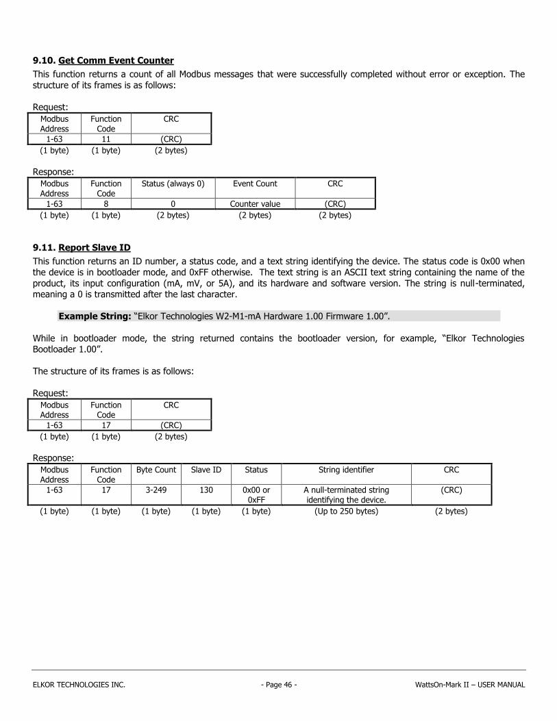
ELKOR TECHNOLOGIES INC. - Page 46 - WattsOn-Mark II – USER MANUAL
9.10. Get Comm Event Counter
This function returns a count of all Modbus messages that were successfully completed without error or exception. The
structure of its frames is as follows:
Request:
Modbus Address
Function Code
CRC
1-63 11 (CRC)
(1 byte) (1 byte) (2 bytes)
Response:
Modbus Address
Function Code
Status (always 0) Event Count CRC
1-63 8 0 Counter value (CRC)
(1 byte) (1 byte) (2 bytes) (2 bytes) (2 bytes)
9.11. Report Slave ID
This function returns an ID number, a status code, and a text string identifying the device. The status code is 0x00 when
the device is in bootloader mode, and 0xFF otherwise. The text string is an ASCII text string containing the name of the
product, its input configuration (mA, mV, or 5A), and its hardware and software version. The string is null-terminated, meaning a 0 is transmitted after the last character.
Example String: “Elkor Technologies W2-M1-mA Hardware 1.00 Firmware 1.00”.
While in bootloader mode, the string returned contains the bootloader version, for example, “Elkor Technologies Bootloader 1.00”.
The structure of its frames is as follows:
Request:
Modbus Address
Function Code
CRC
1-63 17 (CRC)
(1 byte) (1 byte) (2 bytes)
Response:
Modbus Address
Function Code
Byte Count Slave ID Status String identifier CRC
1-63 17 3-249 130 0x00 or 0xFF
A null-terminated string identifying the device.
(CRC)
(1 byte) (1 byte) (1 byte) (1 byte) (1 byte) (Up to 250 bytes) (2 bytes)

ELKOR TECHNOLOGIES INC. - Page 47 - WattsOn-Mark II – USER MANUAL

Elkor Technologies Inc. 6 Bainard Street London, Ontario
N6P 1A8
Tel: 519-652-9959 Fax: 519-652-1057
www.elkor.net
© 2015, Elkor Technologies Inc.
Related Documents