Precision 28144 Quad-Channel Wideband Transducer Conditioner with Voltage and Current Excitation and REZCOMP® Technology On the New Frontiers of Precision Precision 28144 for the 28000 Analog Signal Conditioner Overview 28000 Analog Signal Conditioning System Precision 28144 Features • Four channels per card, 64 channels per 28016 chassis • Balanced programmable constant voltage excitation with remote sense – up to 20 V delivered to the bridge • Balanced differential constant current excitation (20 mA/20 V compliance) with AC current test mode for verifying transducer, cabling and frequency response • REZCOMP™ technology to extend frequency response of accelerometer, unsteady pressure and microphone sensor measurements • On-the-fly report of measured transducer excitation, resistance and transducer open/short indication 28144 Applications • Static or dynamic strain gage conditioner • Full bridge conditioner • Pressure transducer conditioner • Piezoresistive accelerometer conditioner • Extended frequency accelerometer, unsteady and pressure measurements • RTD conditioner • Load cell conditioner • MEMS transducer conditioner • Hot wire anemometry • AC or DC filter/amplifier (<1 mV to 10 V inputs) The Precision 28000 Signal Conditioning System provides all the flexibility you need to manage your test measurements. • Choose charge, IEPE w/TEDS, voltage (filter amplifier), strain, thermocouple, RTD, potentiometer, current, frequency, or other transducers. • Graphical User Interface (GUI) and Ethernet network interface for system control • Intelligent gain and system scaling algorithms • Test input and output monitor busses • Go/no-go test with diagnostics to be used before tests • Rigorous factory acceptance test for maintenance • Field swappable AC power supplies • Built-in temperature and power supply monitoring with alarms REZCOMP® Overview Precision Filters in collaboration with Kulite Semiconductor Products developed the patent pending REZCOMP technology to extend the frequency response of pressure sensors, accelerometers, microphones and other resonant sensors in real-time with no need for post-processing. Resonances from recessed mounting of pressure sensors, the protective screen covering the sensor element or even the seismic mass of an accelerometer are effectively compensated by REZCOMP. Using data provided by the sensor manufacturer, the user enters the frequency and Q characteristics of the resonance result- ing in correction of sensor amplitude and phase response. The application of REZCOMP technology typically extends useable sensor bandwidth by 200-300% 1 or more. rezcomp ® 28144 Quad-Channel Wideband Transducer Conditioner with Voltage and Current Excitation and REZCOMP® Technology offers four channels of condi- tioning to support a wide variety of transducers including those that require constant voltage excitation or constant current excitation. Balanced constant voltage excitation in a bridge configuration supports applications such as strain gages and pressure transducers. Balanced current excitation accommodates single arm static or dynamic strain gages, RTDs or other resistive transducers that require constant current to excite them. Gain is programmable to x8192. The 28144 features patent pending REZCOMP transducer compensation technol- ogy that extends the useable frequency response of resonant sensors. REZCOMP is effective at compensating the seismic mass resonant response of an accelerometer, the organ pipe resonant response of a recessed mounted pressure sensor and the resonant response associated with the protective screen of a pressure or microphone sensor. Based on a characterization of the sensor Q and resonance frequency, the compensation tech- nique extends the usable sensor bandwidth by a factor of 3 or more. • Transducer leakage resistance measurement in constant current excitation mode, Option L • Automatic bridge balance/transducer suppress • Up to 204.6 kHz “filtered” bandwidth or 500 kHz “wide-band” bandwidth • 2 to 10-wire plus shield bridge input interface • 2 or 4-wire input plus shield transducer interface with constant current excitation • Programmable AC/DC input coupling • Programmable gain: x1/16 to x8192 with 0.05% vernier • 4 or 8-pole low-pass filters with programmable pulse/flat characteristics • Overload detection • Precise digital calibration • Programmable 5000 step (BC6 completion module) or single step (BC7 completion module) bipolar shunt cal • Programmable bridge configuration: 1-arm, 2-arm or 4-arm bridges • Programmable bridge resistance: 120 Ω, 350 Ω or 1 kΩ • Front panel connectors that accept output adapter modules for multiple buffered outputs per channel

Welcome message from author
This document is posted to help you gain knowledge. Please leave a comment to let me know what you think about it! Share it to your friends and learn new things together.
Transcript

www.pfinc.com Page 1
Precision 28144Quad-Channel Wideband Transducer Conditioner with Voltage and Current Excitation and REZCOMP® Technology
On the New Frontiers of Precision
Precision 28144 for the 28000 Analog
Signal ConditionerOverview
28000 Analog Signal Conditioning System
Precision 28144 Features• Four channels per card, 64 channels per 28016 chassis
• Balanced programmable constant voltage excitation with remote sense – up to 20 V delivered to the bridge
• Balanced differential constant current excitation (20 mA/20 V compliance) with AC current test mode for verifying transducer, cabling and frequency response
• REZCOMP™ technology to extend frequency response of accelerometer, unsteady pressure and microphone sensor measurements
• On-the-fly report of measured transducer excitation, resistance and transducer open/short indication
28144 Applications• Static or dynamic strain
gage conditioner
• Full bridge conditioner
• Pressure transducer conditioner
• Piezoresistive accelerometer conditioner
• Extended frequency accelerometer, unsteady and pressure measurements
• RTD conditioner
• Load cell conditioner
• MEMS transducer conditioner
• Hot wire anemometry
• AC or DC filter/amplifier (<1 mV to 10 V inputs)
The Precision 28000 Signal Conditioning System provides all the flexibility you need to manage your test measurements.
• Choose charge, IEPE w/TEDS, voltage (filter amplifier), strain, thermocouple, RTD, potentiometer, current, frequency, or other transducers.
• Graphical User Interface (GUI) and Ethernet network interface for system control
• Intelligent gain and system scaling algorithms
• Test input and output monitor busses
• Go/no-go test with diagnostics to be used before tests
• Rigorous factory acceptance test for maintenance
• Field swappable AC power supplies
• Built-in temperature and power supply monitoring with alarms
REZCOMP® OverviewPrecision Filters in collaboration with Kulite Semiconductor Products developed the patent pending REZCOMP technology to extend the frequency response of pressure sensors, accelerometers, microphones and other resonant sensors in real-time with no need for post-processing. Resonances from recessed mounting of pressure sensors, the protective screen covering the sensor element or even the seismic mass of an accelerometer are effectively compensated by REZCOMP. Using data provided by the sensor manufacturer, the user enters the frequency and Q characteristics of the resonance result-ing in correction of sensor amplitude and phase response. The application of REZCOMP technology typically extends useable sensor bandwidth by 200-300%1 or more.
rezcomp®
28144 Quad-Channel Wideband Transducer Conditioner with Voltage and Current Excitation and REZCOMP® Technology offers four channels of condi-tioning to support a wide variety of transducers including those that require constant voltage excitation or constant current excitation. Balanced constant voltage excitation in a bridge configuration supports applications such as strain gages and pressure transducers. Balanced current excitation accommodates single arm static or dynamic strain gages, RTDs or other resistive transducers that require constant current to excite them. Gain is programmable to x8192.
The 28144 features patent pending REZCOMP transducer compensation technol-ogy that extends the useable frequency response of resonant sensors. REZCOMP is effective at compensating the seismic mass resonant response of an accelerometer, the organ pipe resonant response of a recessed mounted pressure sensor and the resonant response associated with the protective screen of a pressure or microphone sensor. Based on a characterization of the sensor Q and resonance frequency, the compensation tech-nique extends the usable sensor bandwidth by a factor of 3 or more.
• Transducer leakage resistance measurement in constant current excitation mode, Option L
• Automatic bridge balance/transducer suppress
• Up to 204.6 kHz “filtered” bandwidth or 500 kHz “wide-band” bandwidth
• 2 to 10-wire plus shield bridge input interface
• 2 or 4-wire input plus shield transducer interface with constant current excitation
• Programmable AC/DC input coupling
• Programmable gain: x1/16 to x8192 with 0.05% vernier
• 4 or 8-pole low-pass filters with programmable pulse/flat characteristics
• Overload detection
• Precise digital calibration
• Programmable 5000 step (BC6 completion module) or single step (BC7 completion module) bipolar shunt cal
• Programmable bridge configuration: 1-arm, 2-arm or 4-arm bridges
• Programmable bridge resistance: 120 Ω, 350 Ω or 1 kΩ
• Front panel connectors that accept output adapter modules for multiple buffered outputs per channel
Page 2 Precision Filters, Inc.
Precision 28144 DescriptionPrecision 28144 DescriptionThe 28144 is a member of the Precision 28000 family of signal conditioners. The 28144 pro-vides four channels of conditioning for trans-ducers requiring constant current or constant voltage excitation. Up to sixteen 28144 cards may reside in the 28000 system to provide 64 channels per chassis. In addition, the 28144 may be mixed with other conditioners in the 28000 family to meet your unique signal conditioning requirements.
Large changes in sensor impedance or sensor excitation can indicate that data from this sensor is no longer meaningful. The unique transducer health monitor circuits of the 28144 provide an “on-the-fly” report of measured sensor excitation and resistance. Measured gage resistance is compared to user specified limits and flagged if out of tolerance. Also, the 28144 alerts the user to a transducer open or short condition. The input overload detector reports overloads by out-of-band signals which could cause in-band distortion.
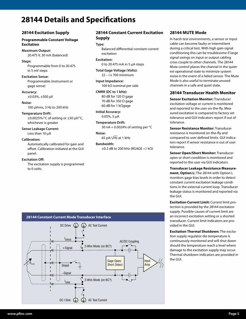
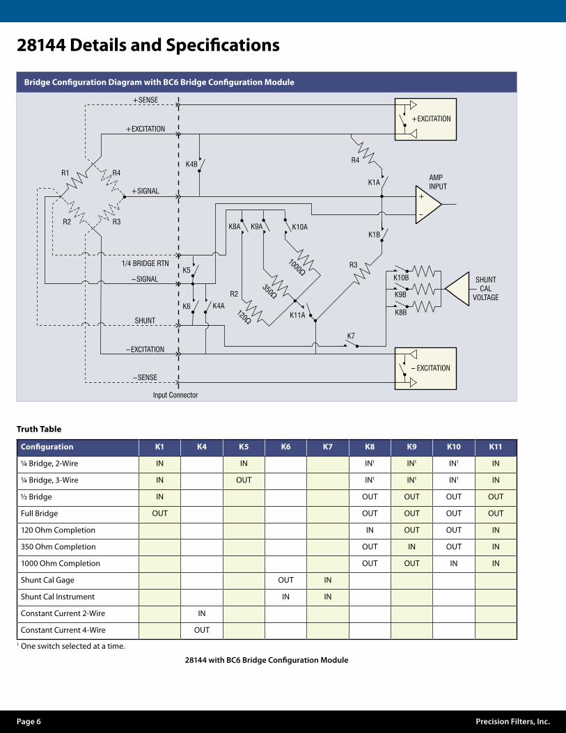
The 28144 features precise, automatic calibra-tion of gain and offset for the entire channel, including the amplifier, filter, and excitation supply. Programmable bridge configura-tion and shunt calibration are supported on all four channels of the 28144 card via the optional BC plug-on module. The BC6 or BC7 modules support programmable bridge con-figuration for quarter, half or full bridges and programmable completion for 120 Ω, 350 Ω or 1 kΩ bridges. The BC6 provides over 5000 steps of bipolar shunt calibration while the BC7 has bipolar single-step precision resis-tor shunt cal. Dedicated shunt cal lines are provided that allow the user to perform the shunt cal on non-current carrying leads.
Balanced Constant Voltage ExcitationThe 28144 provides balanced constant volt-age excitation of up to 20 volts and condi-tioning for 1-, 2-, and 4-arm resistive bridges. The 2- to 10-wire input connection provides 6 wires for the bridge, 3 wires for shunt cali-bration, 1 wire for the shield, and 1 wire for single-arm bridges. Automatic balance of the bridge is accomplished by inserting a voltage ratiometric with the excitation supply to the amplifier input stage. This balance method provides outstanding stability without load-ing the bridge. A wide range of unbalanced conditions may be accommodated.
Balanced constant voltage excitation offers a number of advantages over single-ended excitation. It enables a true balanced instru-mentation amplifier input for outstanding rejection of high frequency common mode signals. Single-ended voltage excitation to balanced bridges produces a relatively large common mode voltage at half the excitation supply. The instrumentation amplifier must reject this signal. Balanced voltage excitation applied to balanced bridges results in lower common mode input voltages to the ampli-fier input stage.
The excitation supply has automatic ampli-tude and offset correction that may be run on the unit in place at any time. Dedicated remote sense lines allow the excitation supply regulator to deliver an accurate volt-age to the bridge.
Balanced Constant Current Excitation™The 28144 is equipped with Precision Filters’ proprietary balanced differential constant current excitation that is optimized for making dynamic strain measurements on single active strain gages. Balanced constant current excitation provides an accurate means of measuring dynamic strain with a single active strain gage using only a two-wire connection. Electrostatic pickup is reduced when compared to single-ended constant current excitation or a quarter bridge configuration with remote completion resistors or unbalanced current sources. The balanced current excitation circuit operates properly even under certain common gage fault conditions such as a direct short of the gage to the test model.
Balanced constant current excitation pro-vides a true balanced input for rejection of common-mode signals. Programmable excitation provides 0 to ±20 mA of constant current with an “excitation off” mode to detect input cable noise pickup. Gage open/short detection is also provided.
For dynamic strain conditioning applications, the 28144 can provide accurate measure-ments with only two wires by AC coupling the input. For best AC or DC measurements (required for RTD type transducers), the 28144 provides a 4-wire Kelvin connection for remote sense. Constant current excitation may be applied to full bridge applications with the advantage that excitation delivered to the bridge is unaffected by excitation supply lead wire resistance.
Suppression of the gage DC operating point is performed automatically using the zero suppress feature of the 28144. Zero suppress allows the use of more gain to emphasize small gage fluctuations. Zero suppress also provides the user with an accurate means to balance a full bridge.
The excitation current source output may be modulated to allow AC current injection in the loop. The frequency and amplitude of the AC current is user controlled. This allows the user to simulate changes in gage resistance in the loop and provides direct AC input stimulation to the signal conditioner for end-to-end system calibration.
REZCOMP TechnologyPrecision Filters developed the patent pend-ing REZCOMP technology to extend the fre-quency response of accelerometers, pressure sensors and microphones in real-time with no need for data post-processing. For mea-surement of unsteady pressure, aerodynami-cally driven resonances associated with the sensor packaging and/or recessed mounting can produce large gain and phase errors in the frequency range of interest (10 Hz to 20 kHz).
When the pressure sensor is packaged in the transducer housing, a protective screen cov-ering the sensing element is used. The screen and the cavity volume behind the screen produce Helmholtz resonances on the order of 20 kHz to 100 kHz which overlap and limit the usable sensor frequency response. The resonance causes unwanted amplification and phase shift errors in the measurement and if not accounted for, can exceed the maximum signal swing of the amplifier and severely distort the measurement.
Similarly, for applications where the sensor is recessed at the end of a tube, an organ-pipe resonance is created that amplifies the pres-sure signal by 20 dB or more depending on the length of the tube and other properties. This resonance limits the useful bandwidth to about 20% of the first resonance or about 1 kHz for a 1 inch tube.
REZCOMP flattens the sensor resonant response and compensates for phase in order to make use of the full available frequency response of the sensor. REZCOMP compensa-tion is based on user entry of sensor quality factor Q and resonance Fr. The complemen-tary transfer function is programmed to flatten the sensor frequency response and linearize the sensor phase response.

www.pfinc.com Page 3
Vendors such as Kulite™ provide Q and Fr data specific to each sensor. For even more accurate results, the sensitivity of Q and Fr to temperature may be accounted for simply by entering the operating temperature of the sensor1.
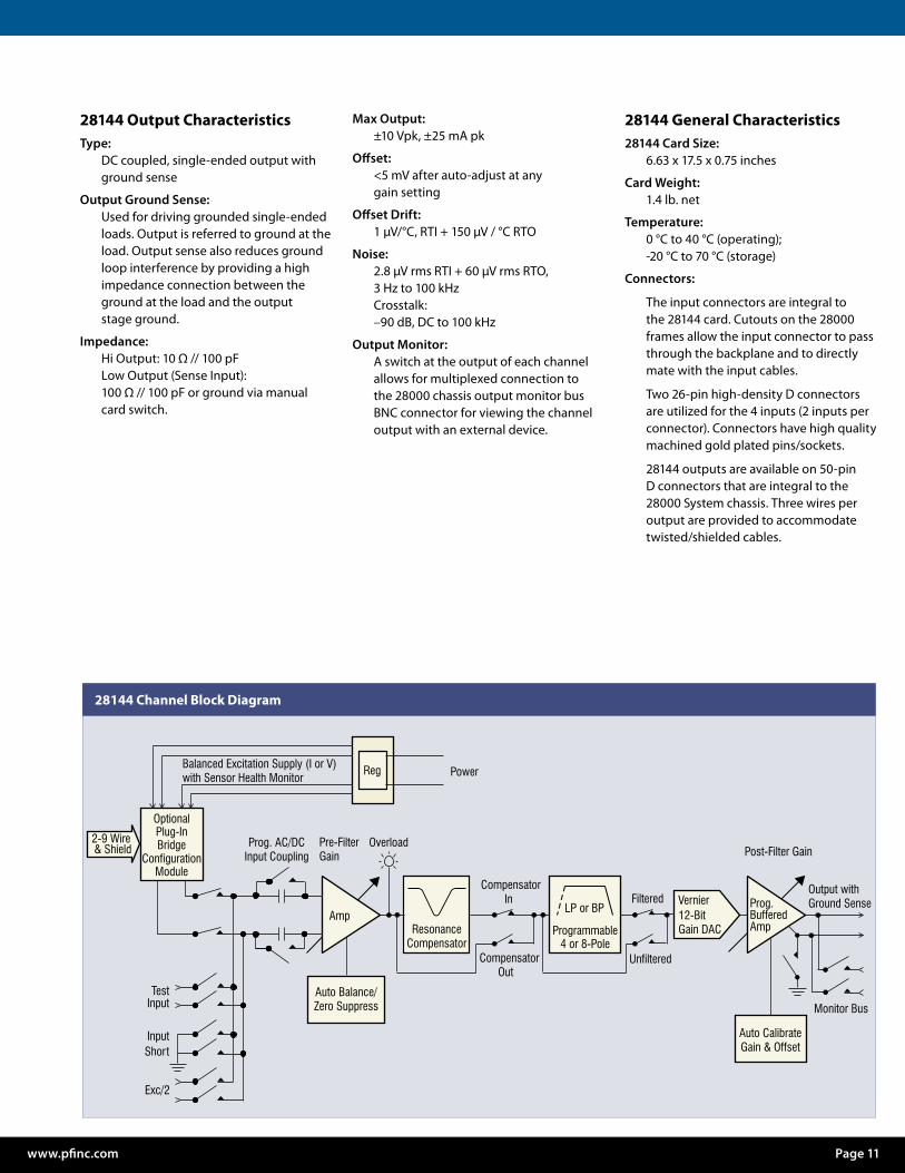
As the block diagram on page 11 illustrates, programmable pre-filter gain is first applied to the input signal in order to preserve signal-to-noise ratio of the in-band sensor signal while allowing for headroom for out-of-band signals. Next the sensor frequency response correction is applied to compensate for the resonant response of the sensor. The pro-grammable filter is then applied to the signal to eliminate out band energy and to prevent aliasing. The signal is then further amplified using post-filter gain to ensure the full use of the A/D dynamic range after compensation of the resonance characteristics.
It is possible to correct for undesired reso-nant frequencies by post-processing test data however post-processing data after digitiza-tion can result in poor signal-to-noise ratios since the A/D input must accommodate both the in-band signal of interest and the sensor resonance. Allocating amplifier headroom for the sensor resonance results in reduced amplification of the small in-band signal above the self-noise of the signal conditioner and A/D. This results in sub-optimal signal-to-noise ratios regardless of the resolution of the A/D. The REZCOMP correction approach provides superior real-time performance by maximizing signal-to-noise ratios.
Input StageThe 28144 input stage provides 120 dB of common-mode rejection and may be either AC or DC coupled. AC coupling is useful for dynamic applications where the DC bias on the transducer, that can limit dynamic range, can be coupled out of the signal. With the input DC coupled, low drift and ultra low noise (< –163 dBV/√Hz) is provided by the 28144 input stage. The input stage may be shorted under program control to verify signal conditioner channel noise and DC offsets.
A switch at the input stage is provided to connect the amplifier to the 28000 system test bus. The test bus is used to inject signals for performance verification. In addition, both drive and sink current levels may be monitored separately making it possible to detect excitation current leakage conditions in the external current loop.
Amplifier and FilterProgrammable pre- and post-filter ampli-fiers provide an overall gain of 8192. Gain is distributed both before and after the filter to provide protection from large out-of-band energy or transients that could cause clip-ping before the filter, distorting the data. The Gain Wizard in the GUI allows the user to set a gain reserve and then apportions the gain between the input and output. This provides input gain for best noise performance yet conforms to the limitations of the user’s worst case estimate of out-band or transient signals. Overload detectors alert the user to over-voltage conditions. A fully buffered output having over 25 mA of drive capability may be used to drive long output cable runs.
The 28144 may be specified with a 4 or 8-pole low-pass filter or an 8-pole band-pass filter with cutoffs programmable from 1 Hz to 204.6 kHz and programmable “flat” or “pulse” mode. The “flat” mode provides pass-band characteristics nearly identical to a Butter-worth filter while providing a much sharper roll-off. This mode is a good choice for appli-cations such as spectral analysis. The “pulse” mode has time domain response similar to the Bessel filter yet provides superior ampli-tude response characteristics. The “pulse” mode is ideal for time domain applications including transient (shock) measurements and time domain waveform analysis.
Verification of Cables and Sensor HealthStrain Gage Loop Resistance Measure-ment: Dynamic strain measurements often require complicated wiring schemes. Long cable runs, multiple connection points, high-temperature high-impedance very small diameter wire and slip rings combine to cause uncertainty in the strain gage connec-tion. Often a sudden increase in gage resis-tance is a predictor of gage failure. The Preci-sion 28144 gives continual real time monitor-ing of the total “Loop Resistance” of the gage and cable circuit. This loop resistance reading can be compared to preset limits to alert the user of unexpected resistance shifts as well as gross gage short and gage open conditions.
Cable Roll-off: One often asked question of many measurements engineers is “How will my cable capacitance affect my high frequency strain measurement”? This ques-tion can be answered quickly and easily and all from the convenience of the control room. The AC dither current feature of the 28144 modulates a small AC current on top of the DC excitation current to stimulate an AC signal across the actual strain gage sensing element. Since the stimulus signal is based at the sensor, it will exhibit the same roll-off characteristics as a signal resulting from actual dynamic strain. The test frequency of the dither signal can be increased as neces-sary to chart the cable roll-off characteristics and validate the cable circuit for use at the desired measurement frequencies.
Gage Leakage Measurements: In extremely hot sections of a gas turbine engine, it is impossible to use standard insulating materi-als in gage wiring. Often a rigid section of a stainless steel or Inconel sheath encloses high temperature inner conductor wires. The inner core of the sheath is filled with mag-nesium oxide (MGO) as a high temperature insulating material. The insulating properties of the MGO are affected by moisture absorp-tion at damage points or improperly sealed cable terminations. In extreme conditions, insulation breakdown can cause a leakage path to ground and corrupt a gage reading. Other causes of cable leakage are fatigue or failure at extension wire tie-down points, or in the strain gage itself. The leakage detec-tion feature of the 28144 continually monitors leakage and compares readings to preset thresh- hold limits. Sensors which show higher than normal leakage can be quickly identified prior to or during the test run.
Muting Faulty SensorsDepending on the sensor type, various tech-niques must be used to quiet the channel’s input and output circuits and ensure that no noise coupling occurs. For example, an inter-mittent gage will create a gage chatter condi-tion whereby the connecting wires continu-ally switch between the high voltage fault level and the proper low voltage operational level. This chatter condition creates a hostile noise source to any other gage extension wires in the vicinity of the hostile cable. Preci-sion 28144 signal conditioning channels have a “MUTE” feature, which places the channel in its quietest quiescent state and minimizes the possibility of coupling noise to properly functioning channels.
1 Hurst, A. M., Carter S., Firth D., Szary A., and VanDeWeert, J., 2015, “Real-Time, Advanced Electrical Filtering for Pressure Transducer Frequency Response Correction,” ASME 2015 Gas Turbo Expo, ASME, Montreal, Canada, pp. 1-13
™ Balanced Constant Current and BCC are Trademarks of Precision Filters, Inc.
REZCOMP® and the REZCOMP logo® are used by Precision Filters, Inc. under license from Kulite Semiconductor Products, Inc.

28144 Details and SpecificationsProgrammable Bridge Configuration ModulesConstant Voltage Excitation Mode:The optional BC plug-on bridge configura-tion modules provide support for program-mable bridge configuration. In addition, the BC6 and BC7 modules support program-mable shunt calibration for all four channels on the 28144 card when using constant voltage excitation. The BC8 module provides conditioning for modulated current output transducers, such as those with 4-20 mA outputs.
All completion modules may be programmed to support 1-arm, 2-arm or 4-arm (quarter, half or full) bridge configurations. Comple-tion resistance is programmable for 120 Ω, 350 Ω or 1 kΩ. Completion resistors are metal foil technology and are very precise and very stable.
The BC6 shunt calibration utilizes voltage insertion at the bridge, providing over 5000 steps of single shunt calibration of bridge arms R1 or R2. The user may program the shunt to be applied at the gage (if additional cable wires are used) or at the instrument. Shunt sensitivity is set by a precision resistor on the BC6 card and is programmable from ±125 µV per V of programmed excitation to ±8 mV/V in 0.2% resolution. The effective range of shunt resistor values is 30.75 to 2000 times the bridge programmed bridge resis-tance. The BC6 shunt calibration may only be used in conjunction with constant voltage excitation.
The BC7 provides traditional single-step bipolar shunt cal using a precision resistor. Single shunt of either R1 or R2 bridge arms may be selected. The standard BC7 shunt cal supplied with 120 Ω, 350 Ω and 1 kΩ cards produces 1 mV/V single shunt. Custom shunt resistor values may be specified.
The BC8 supports 2-wire or 4-wire connec-tions to modulated current output devices that require a constant voltage power supply to excite them and provide a current output proportional to the measurement units. This includes sensors with 4-20 mA outputs. The BC8 switches a 250 ohm resistor across the amplifier input to measure the sensor current output.
The BC9 completion module supports pro-grammable bridge completion only.
Constant Current Excitation Mode:When using constant current excitation, the bridge configuration modules provide programmable configuration of 2-wire or 4-wire input mode. 2-wire mode is useful for dynamic strain measurements where the input stage of the amplifier is AC coupled. The 4-wire mode may be used to make static measurements with a Kelvin connection to the gage. The 28144 zero suppress circuit can be used to zero the transducer bias when operating in the 4-wire configuration. The wide range of the zero-suppress circuit can accommodate large transducer bias voltages.
Bridge Configuration Module Specifications:Completion Resistors:
120 Ω, 350 Ω and 1 kΩ, programmable
Bridge Configuration:1-arm, 1-arm w/ 3 wires, 2-arm or 4-arm, (programmable)
Resistor Temperature Coefficient:±0.2 ppm / °C
Resistor Accuracy:±0.02%
BC6 Shunt Calibration (Constant Voltage Excitation Mode Only):Shunt Selection:
R1 or R2 bridge arms
Equivalent Shunt Resistance Settings:30.75R to 2000R w/ 0.2% minimum resolution where R = 120 Ω, 350 Ω or 1 kΩ
Shunt Sensitivity: ±0.125 mV/V to ±0.5 mV/V in ±0.25µV/V steps±0.501 mV/V to ±2.0 mV/V in ±1.00 µV/V steps ±2.004 mV/V to ±8.0 mV/V in ±4.00 µV/V steps
Shunt Accuracy: ±0.2% for programmed excitation >1 V
BC7 Shunt Calibration:Shunt Selection:
R1 or R2 bridge arms
Shunt Sensitivity:±1 mV per volt of programmed excitation
Shunt Resistance: 29.940 kΩ for 120Ω bridge87.325 kΩ for 350Ω bridge249.5 kΩ for 1 kΩ bridge
Resistor Accuracy:±0.1%
BC8 Current Sense:
Modes: 2-wire sense or 4-wire sense
Sense Resistor: 250 ohms ±0.1%
Bridge WiringInput Connector:
26-pin D-shell (2 ea.)
Input Wires:±EXCITATION (2)±SENSE (2)±SIGNAL (2)SHUNT CAL (3)¼ Bridge RTN (1) Single Arm BridgeSHIELD (1)
Page 4 Precision Filters, Inc.
28144 Details and Specifications28144 Excitation Supply
Programmable Constant Voltage Excitation
Maximum Output:20.475 V, 30 mA (balanced)
Steps:Programmable from 0 to 20.475 in 5 mV steps
Excitation Sense:Programmable (instrument or gage sense)
Accuracy:±0.03%, ±500 µV
Noise:100 µVrms, 3 Hz to 200 kHz
Temperature Drift:±0.0025%/°C of setting or ±50 µV/°C, whichever is greater
Sense Leakage Current:Less than 10 µA
Calibration:Automatically calibrated for gain and offset. Calibration initiated at the GUI panel.
Excitation Off:The excitation supply is programmed to 0 volts.
28144 Constant Current Excitation SupplyType:
Balanced differential constant current excitation
Excitation: 0 to 20.475 mA in 5 µA steps
Total Gage Voltage (Volts):22 – I x 700 minimum
Input Impedance:100 kΩ nominal per side
CMRR (DC to 1 kHz):80 dB for 120 Ω gage70 dB for 350 Ω gage60 dB for 1 kΩgage
Initial Accuracy: 0.05%, 5 µA
Temperature Drift: 30 nA + 0.0024% of setting per °C
Noise: 65 pA/√Hz at 1 kHz
Bandwidth: ±0.2 dB to 200 kHz (RGAGE <1 kΩ)
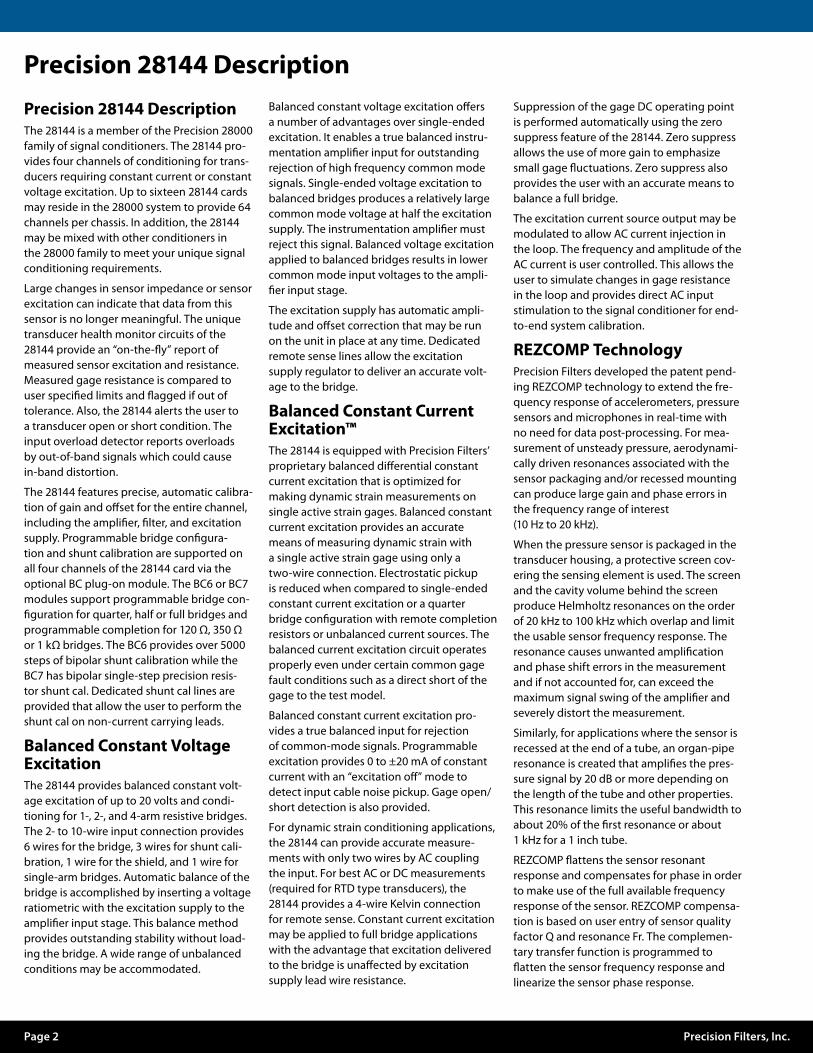
28144 MUTE ModeIn harsh test environments, a sensor or input cable can become faulty or intermittent during a critical test. With high gain signal conditioning this can be troublesome if large signal swings on input or output cabling cross couple to other channels. The 28144 Mute control places the channel in the quiet-est operational state to minimize system noise in the event of a failed sensor. The Mute Mode is also useful to terminate unused channels in a safe and quiet state.
28144 Transducer Health MonitorSensor Excitation Monitor: Transducer excitation voltage or current is monitored and reported to the user on-the-fly. Mea-sured excitation is compared to factory set tolerance and GUI indicators report if out of tolerance.
Sensor Resistance Monitor: Transducer resistance is monitored on-the-fly and compared to user defined limits. GUI indica-tors report if sensor resistance is out of user tolerance.
Sensor Open/Short Monitor: Transducer open or short condition is monitored and reported to the user via GUI indicators.
Transducer Leakage Resistance Measure-ment, Option L: The 28144 with Option L monitors gage bias levels in order to detect constant current excitation leakage condi-tions in the external current loop. Transducer leakage status is monitored and reported via the GUI.
Excitation Current Limit: Current limit pro-tection is provided by the 28144 excitation supply. Possible causes of current limit are an incorrect excitation setting or a shorted transducer. Current limit indicators are pro-vided in the GUI.
Excitation Thermal Shutdown: The excita-tion supply regulator die temperature is continuously monitored and will shut down should the temperature reach a level where damage to the excitation supply may occur. Thermal shutdown indicators are provided in the GUI.Gage Open/
Short DetectInputAmpShield
RGAGE
DC Drive AC Test Current
DC I Sink AC Test Current
+Signal
–Signal
I DRIVE
ISINK
AC/DC Coupling
2-Wire Mode (on BC?)
2-Wire Mode (on BC?)
28144 Constant Current Mode Transducer Interface
www.pfinc.com Page 5
28144 Details and Specifications
R2 R3
R1
+SENSE
R4
+EXCITATION+EXCITATION
– EXCITATION
+SIGNAL
1/4 BRIDGE RTN
–SIGNAL
SHUNT
–EXCITATION
–SENSE
Input Connector
R4
R3
R2
K4B
K5
K6 K4A
Bridge Con�guration Diagram with BC6 Bridge Con�guration Module
K10A
K11A K8B
K9B
K10B
K1B
K1A
K9AK8A
K7
1000Ω
350Ω
120Ω
+
–
SHUNTCAL
VOLTAGE
AMPINPUT
Truth Table
Configuration K1 K4 K5 K6 K7 K8 K9 K10 K11
¼ Bridge, 2-Wire IN IN IN1 IN1 IN1 IN
¼ Bridge, 3-Wire IN OUT IN1 IN1 IN1 IN
½ Bridge IN OUT OUT OUT OUT
Full Bridge OUT OUT OUT OUT OUT
120 Ohm Completion IN OUT OUT IN
350 Ohm Completion OUT IN OUT IN
1000 Ohm Completion OUT OUT IN IN
Shunt Cal Gage OUT IN
Shunt Cal Instrument IN IN
Constant Current 2-Wire IN
Constant Current 4-Wire OUT
1 One switch selected at a time.
28144 with BC6 Bridge Configuration Module
Page 6 Precision Filters, Inc.
R2 R3
R1
+SENSE
+SHUNT
R4
+EXCITATION+EXCITATION
– EXCITATION
+SIGNAL
1/4 BRIDGE RTN
–SIGNAL
SHUNT
–EXCITATION
–SENSE
–SHUNT
Input Connector
R4
R3
R2
K4B
K5
K6 K4A
K3A
Bridge Con�guration Diagram with BC7 Bridge Con�guration Module
K10A
K11A K8B
K9B
K10B
K1B
K1A
K9AK8A
K7
1000Ω
350Ω
120Ω
+
–
AMPINPUT
K3A
K21
2
Truth Table
Configuration K1 K2 K3, K6 K4 K5 K7 K8 K9 K10 K11
¼ Bridge, 2-Wire IN IN IN1 IN1 IN1 IN
¼ Bridge, 3-Wire IN OUT IN1 IN1 IN1 IN
½ Bridge IN OUT OUT OUT OUT
Full Bridge OUT OUT OUT OUT OUT
120 Ohm Completion IN OUT OUT IN
350 Ohm Completion OUT IN OUT IN
1000 Ohm Completion OUT OUT IN IN
Shunt Cal Gage OUT IN
Shunt Cal Instrument IN IN
Shunt R1 1 IN
Shunt R2 2 IN
Constant Current 2-Wire IN
Constant Current 4-Wire OUT
1 One switch selected at a time.
28144 with BC7 Bridge Configuration Module
www.pfinc.com Page 7

You want your analog data to come clean before digital conversion.The 28144 Card has a variety of high perfor-mance filter characteristics available for HP, LP or BP Precision filtering.
Flat/Pulse Low-Pass FiltersOur new choice of LP4FP 4-pole or LP8FP 8-pole flat/pulse low-pass filters provide the user with the versatility to address applica-tions in either the time or frequency domain and are available on many 28000 card models. Frequencies can range as high as 204.6 kHz with fixed frequency choices for economy.
Flat Mode Low-Pass FiltersPrecision LP4F and LP8F “flat” mode char-acteristics are specified to have outstand-ing passband flatness equivalent to the Butterworth yet deliver very sharp roll-off characteristics.
The LP4F and LP8F are a good choice as an anti-aliasing filter and for applications such as spectral analysis. The LP8F has zero passband ripple and over 100 dB/octave attenuation slope.
Pulse Mode Low-Pass FiltersFor the time domain, there are the LP4P and LP8P “pulse” mode low-pass filters. These filters have excellent transient response and phase linearity making them ideal filters for time domain applications including transient (shock) measurements and time domain wave-form analysis … all with roll-off characteristics superior to their Bessel filter counterparts.
High-Pass and Band-Pass Filters For high-pass filtering, we offer the HP4F 4-pole characteristics. For band-pass filtering, choose the HP4F/LP4FP band-pass character-istic to provide programmable bandwidth and center frequency filters.
REZCOMP Sensor CompensionPatent pending REZCOMP™ technology extends the frequency response of acceler-ometers, pressure sensors and microphones in real-time with no need for data post-pro-cessing. Based on user entry of sensor Q and resonant frequency, REZCOMP extends usable sensor bandwidth by a factor of two or more.
When applied to an accelerometer with Q of 10, REZCOMP extends useable 5% bandwidth by a factor of 5X as shown below.
The cavity resonant response caused by the protective screen of a microphone or a recess mount pressure sensor is reduced using REZCOMP technology.
Traditional FiltersOf course, we offer the traditional filter types such as Butterworth and Bessel characteristics … just ask!
In any case, we deliver to you a tightly con-trolled filter with phase match better than 1 degree and usually better than 0.5 degrees.
Page 8 Precision Filters, Inc.
Gain
(dB)
Normalized Frequency (f/Fc)
LP4F and LP4P Amplitude Response
0
–15
–30
–45
–60
–75
–90
–105.1 .2 .7.4 10 20 40 1001 702 4 7
LP4F LP4P
Gain
(dB)
Normalized Frequency (f/Fc)
LP8F and LP8P Amplitude Response
0
–15
–30
–45
–60
–75
–90
–105.1 .2 .3 .4 2 3 4 6 8 10
LP8F LP8P
.6 .8 1.0 5
Compensated Seismic Sensor Amplitude Response
Normalized Frequency (f/Fr)
Gain
(dB)
4030
20
10
0
–10
–20
–30–40
0.1 0.2 0.3 0.5 0.7 1 2 3 5 7 10
Compensated Sensor
Uncompensated Sensor
Compensated Sensor Cavity Resonance, Fr = 30 kHz, Q = 8
Frequency (Hz)
Gain
(dB)
2015
10
5
0
–10
–5
–5.0–20
3k 5k 7k 10k 20k 30k 50k 70k 100k 200k 300k
Sensor Response(Uncompensated)
CompensatedResponse REZCOMP
Compensator
LP4P vs Bessel Step Response
0 1.0 2.01.6 1.8Time x Fc (Sec x Hz)
Resp
onse
/Fin
al Va
lue
1.2
1.4
1.0
0.8
–0.2
0
0.2
0.4
0.6
.2 .4 .6 1.2 1.4.8
LP4P
4-Pole Bessel(for Comparison)
Band-Pass Amplitude Response HP4F and LP4F Cascaded
.1 1 1063 8Normalized Frequency (f/Fc)
Gain
(dB)
–10
0
–20
–30
–80
–70
–60
–50
–40
α = 4 2 1
Q = 0.67
1.31
.2 .3 .4 .6 2 4.8
2.32
α = FLP/FHP
FLP = √α FO
FHP = FO/√αFO = √FLP FHP
28144 Filter Characteristics

www.pfinc.com Page 9
28144 Filter Type CharacteristicsOption LP4FP:
4-pole, 4-zero low-pass filter. Programmable for maximally flat pass-band (LP4F) or linear phase with optimized pulse response (LP4P).
Option LP8FP:8-pole, 8-zero low-pass filter. Programmable for maximally flat pass-band (LP8F) or linear phase with optimized pulse response (LP8P).
Option HP4F/LP4FP:8-pole, 8-zero band-pass filter. Flat HP4F 4-pole, 4-zero high-pass filter cascaded with a 4-pole, 4-zero low-pass filter. Low-pass filter programmable for maximally flat pass-band (LP4F) or linear phase with optimized pulse response (LP4P).
Option REZC/LP4FP:REZCOMP® sensor compensation cascaded with LP4FP low-pass filter.
Cutoff Frequencies:Flat Mode:
2 Hz to 2.046 kHz in 2 Hz steps 2.2 kHz to 204.6 kHz in 200 Hz steps
Pulse Mode:1 Hz to 1.023 kHz in 1 Hz steps1.1 kHz to 102.3 kHz in 100 Hz steps
Note: Other filter types and cutoff ranges available upon request. Please consult factory.
LP4F, LP4P, LP8F, LP8P:
Amplitude Accuracy:±0.1 dB max, DC to 0.8 Fc±0.2 dB max, 0.8 Fc to Fc
Amplitude Match:±0.1 dB max, DC to 0.8 Fc±0.2 dB max, 0.8 Fc to Fc
Phase Match:±1° max, DC to 0.8 Fc±2° max, 0.8 Fc to Fc
HP4F:
Amplitude Accuracy:±0.1 dB max, 1.2 Fc to 204.6 kHz±0.2 dB max, Fc to 1.2 Fc
Amplitude Match:±0.1 dB max, 1.2 Fc to 204.6 kHz±0.2 dB max, Fc to 1.2 Fc
Phase Match:±1° max, 1.2 Fc to 204.6 kHz±2° max, Fc to 1.2 Fc
REZCOMP (Option REZC)Sensor Compensation Q: 1 to 20 in 0.1 steps;
20 to 50 in 0.5 steps
Sensor Compensation Frequency (Fr):Low-Range: 10 Hz to 2.55 kHz in 10 Hz stepsMid-Range: 2.6 kHz to 51 kHz in 200 Hz stepsHigh-Range: 52 kHz to 255 kHz in 1 kHz steps
Amplitude Accuracy:
Low-Range:±0.1 dB DC to 0.8 Fr; 1.25 Fr ≤ f ≤ 10 kHzQ ≤ 10: ±0.2 dB; 0.8 Fr < f < 1.25 Fr Q > 10: ±0.02 dB * Q; 0.8 Fr < f < 1.25 Fr
Mid-Range:±0.15 dB DC to 0.8 Fr; 1.25 Fr ≤ f ≤ 100 kHzQ ≤ 10: ±0.25 dB; 0.8 Fr < f < 1.25 Fr Q > 10: ±0.025 dB * Q; 0.8 Fr < f < 1.25 Fr
High-Range:±0.2 dB; DC to 0.6 Fr; ±0.5 dB; 1.7 Fr ≤ f ≤ 255 kHzQ ≤ 10: ±1.25 dB; 0.6 Fr < f < 1.7 Fr or 255 kHz whichever is less Q > 10: ±0.125 dB * Q; 0.6 Fr < f < 1.7 Fr or 255 kHz whichever is less
Phase Match:
±2°, DC to 0.8 Fr Low and Mid-Ranges; DC to 0.6 Fr High-Range
Amplitude Match:
±0.2 dB, DC to 0.8 Fr Low and Mid-Ranges; DC to 0.6 Fr High-Range
Specification LP4F Maximally Flat Low-Pass Filter
LP4P Constant Time Delay
Low-Pass Filter
LP8F Maximally Flat Low-Pass Filter
LP8P Constant Time Delay
Low-Pass Filter
HP4F Maximally Flat
High-Pass Filter
Cutoff Frequency Amplitude -3.01 dB -3.01 dB -3.01 dB -3.01 dB –3.01 dB
DC Gain 0.00 dB 0.00 dB 0.00 dB 0.00 dB –80 dB
Stop-Band Frequency 5.9465 Fc 11.863 Fc 1.7479 Fc 3.4688 Fc 0.1682 Fc
Phase Distortion (DC to Fc) < 31.8 deg <3.7 deg <102 deg <0.05 deg –
Percent Overshoot 11.1% 0.5% 18.9% 1.1% –
1% Settling Time 1.65/Fc 0.66/Fc 4.03/Fc 1.25/Fc 1.86/Fc
-0.1 dB Frequency 0.6348 Fc 0.1816 Fc 0.8538 Fc 0.180 Fc 1.5753 Fc
-1 dB Frequency 0.8487 Fc 0.5742 Fc 0.9437 Fc 0.5685 Fc 1.1783 Fc
-3.01 dB Frequency 1.0000 Fc 1.0000 Fc 1.0000 Fc 1.0000 Fc 1.0000 Fc
-40 dB Frequency 2.9555 Fc 5.6932 Fc 1.4443 Fc 2.7556 Fc 0.3384 Fc
-80 dB Frequency 5.9465 Fc 11.8629 Fc 1.7479 Fc 3.4688 Fc 0.1682 Fc
28144 Details and Specifications
28144 Details and Specifications
Page 10 Precision Filters, Inc.
28144 Input CharacteristicsType:
Balanced differential w/ programmable AC/DC input coupling
Input Impedance:10 MΩ //100 pF per side
Max Level (AC + DC + Common Mode):±10 Vpk for f £ 200 kHz ±10 Vpk x (200 kHz/f) for f > 200 kHz
Input Protection (Power On): 45 V continuous, 100 Vpk for 1 mS, 10% duty cycle
Offset Drift:1 µV/°C, typical
Noise:7 nV/ Hz at 1 kHz and pre-filter gain >64, typical
AC Coupling Frequency: 0.25 Hz ( 3.01 dB)
CMRR (DC Coupled): 110 dB, DC to 440 Hz and input gain > x16
CMRR (AC Coupled.): 100 dB, 10 Hz to 440 Hz
Auto Bridge Balance Mode:The bridge is automatically balanced utilizing voltage insertion at the input amplifier when bridge balance mode is selected. The inserted voltage is derived from and thus tracks the excitation supply. A successive approximation A/D converter mechanization is used for rapid bridge balance.
Range:Bridge balance algorithm selects the most appropriate range to achieve balance with finest resolution.
32 mV/V Mode Auto-Balance Ranges: ±0.0002 mV/V to ±0.5 mV/V in ±0.244 µV/V steps±0.502 mV/V to ±4.0 mV/V in ±1.95 µV/V steps±4.016 mV/V to ±32.0 mV/V in ±15.625 µV/V steps
512 mV/V Mode Auto-Balance Ranges (Gain limited to x512):±0.004 mV/V to ±8.0 mV/V in ±3.9 µV/V steps±8.03 mV/V to ±64.0 mV/V in ±31.25 µV/V steps±65.25 mV/V to ±512.0 mV/V in ±250 µV/V steps
Accuracy:±0.1% of setting ±0.1% of F.S. range
Stability: ±25 ppm / ºC of setting
Drift (RTI): ±0.3 µV / °C for 32 mV/V range; ±5 µV / °C for 512 mV/V range
Auto Balance Time: Less than 15 seconds per system of 64 channels.
Auto Suppress Mode: A programmable DC offset derived from a precision 10 V reference is injected at the channel input stage to suppress the gage DC operating voltage. Manual or automatic suppression modes are supported.
640 mV Suppress Ranges: ±0.005 mV to ±10 mV in ±4.9 µV steps±10.04 mV to ±80 mV in ±39 µV steps±80.31 mV to ±640 mV in ±312 µV steps
10.24 V Suppress Ranges (Gain limited to x512):±0.08 mV to ±160 mV in ±78 µV steps±160.6 mV to ±1.28 V in ±625 µV steps±1.285 V to ±10.24 V in ±5 µV steps
Accuracy: ±0.1% of setting ±0.1% of F.S. range
Stability: ±25 ppm / °C of setting
Drift (RTI):±0.3 µV / °C for 640 mV range; ±5 µV / °C for 10.24 V range
Auto Suppress Time: Less than 15 seconds per system of 64 channels.
28144 Amplifier CharacteristicsPre-Filter Gain:
x1 to x512 in binary steps with overload detection (10.5 Vpk threshold)
Post-Filter Gain:x1/16 to x16 in binary steps with vernier adjustment
Overall Gain:x1/16 to x8192
Gain Setability:0.05% steps for POG ≥0.5X 0.05%/POG for POG <0.5X
DC Gain Accuracy:0.01% typical, 0.1% maximum for POG ≥0.5X 0.1%/POG maximum for POG <0.5X
Stability: ±0.02% for 6 months Temp Coef.: ±0.004%/°C
DC Linearity:±0.005% re Fullscale, relative to the best straight line
Frequency Response:DC to 200 kHz, 0 dB ±0.1 dB –3 dB typical @ 500 kHz
High Frequency Rolloff: 18 dB/octave
28144 Test ModesAmplifier Short: A switch at the amplifier input is utilized to ground the input stage for measurement of noise and DC offset.
Test Bus: Test input allows for injection of a test signal. An external test signal or the 28000-?-TEST Test Subsystem may be con-nected at the rear panel. Refer to the 28000-?-TEST Test Subsystem specification for more information.
Shunt Cal: Applies shunt to bridge.
Excitation Monitor (Constant Voltage Mode Only): The amplifier input is switched from the bridge to the excitation supply to monitor the excitation voltage at the ampli-fier output. Excitation monitor gain is x0.5.
Excitation Off: The excitation supply is pro-grammed to zero volts or zero mA.
AC Current (Constant Current Mode Only): An AC current is injected into the current loop to evaluate end-to-end system frequency response. The AC current is generated from a voltage waveform on the test bus.
Dither Bandwidth: (350 ohm loop resistance at input connector):
–5% at 50 kHz, typical
www.pfinc.com Page 11
28144 Output CharacteristicsType:
DC coupled, single-ended output with ground sense
Output Ground Sense: Used for driving grounded single-ended loads. Output is referred to ground at the load. Output sense also reduces ground loop interference by providing a high impedance connection between the ground at the load and the output stage ground.
Impedance:Hi Output: 10 Ω // 100 pFLow Output (Sense Input): 100 Ω // 100 pF or ground via manual card switch.
Max Output:±10 Vpk, ±25 mA pk
Offset:<5 mV after auto-adjust at any gain setting
Offset Drift:1 µV/°C, RTI + 150 µV / °C RTO
Noise:2.8 µV rms RTI + 60 µV rms RTO, 3 Hz to 100 kHzCrosstalk:–90 dB, DC to 100 kHz
Output Monitor: A switch at the output of each channel allows for multiplexed connection to the 28000 chassis output monitor bus BNC connector for viewing the channel output with an external device.
28144 General Characteristics28144 Card Size:
6.63 x 17.5 x 0.75 inches
Card Weight:1.4 lb. net
Temperature:0 °C to 40 °C (operating); -20 °C to 70 °C (storage)
Connectors:
The input connectors are integral to the 28144 card. Cutouts on the 28000 frames allow the input connector to pass through the backplane and to directly mate with the input cables.
Two 26-pin high-density D connectors are utilized for the 4 inputs (2 inputs per connector). Connectors have high quality machined gold plated pins/sockets.
28144 outputs are available on 50-pin D connectors that are integral to the 28000 System chassis. Three wires per output are provided to accommodate twisted/shielded cables.
Plug-InOptional
BridgeConfiguration
Module
AmpLP or BP
Filtered
2-9 Wire& Shield Post-Filter Gain
Programmable4 or 8-Pole
Prog.BufferedAmp
TestInput
InputShort
12-Bit Gain DAC
Vernier
Unfiltered
Pre-FilterGain
PowerRegBalanced Excitation Supply (I or V)with Sensor Health Monitor
Auto CalibrateGain & Offset
Auto Balance/Zero Suppress
Output withGround Sense
Exc/2
Prog. AC/DC Input Coupling
Overload
Monitor Bus
CompensatorIn
CompensatorOut
ResonanceCompensator
28144 Channel Block Diagram
ISO 9001 CERTIFIED QUALIT YP8430 Rev K
Precision Filters, Inc.
240 Cherry Street
Ithaca, New York 14850
Telephone: 607-277-3550
E-mail: [email protected]
Web Site: www.pfinc.com
General CharacteristicsAccessoriesMating ConnectorsPrecision Filters mating connectors accom-modate up to 22-AWG wire and are supplied with high quality metal backshells and gold plated screw machined contacts for high reli-ability connections and long service life.
CONN-IN-26D: High-Density 26-pin D-shell mating output connector with machined crimp pins and metal backshell with strain relief.
CONN-IN-26D-SC: High-Density 26-pin D-shell mating output connector with machined solder cup pins and metal backshell with strain relief.
CONN-OUT-26D: High-Density 26-pin D-shell mating output connector with machined crimp pins and metal backshell with strain relief.
CONN-OUT-26D-SC: High-Density 26-pin D-shell mating output connector with machined solder cup pins and metal back-shell with strain relief.
Output AdaptersMeasurement systems often require multiple outputs per signal conditioning channel or special functions such as a DC output in proportion to the AC signal level. These out-puts may be routed to control systems, tape backup systems, auxiliary data acquisition systems, scope bays and other destinations.
28144 cards are fitted with front panel connectors which accept Precision output adapter modules. Adapters plug on to the front of the signal conditioner card and are secured to the card by two screws. The adapters provide one or two additional fully buffered outputs per channel or RMS to DC functionality.
28000-RMS/DC4: Quad RMS-to-DC Con-verter Module
BUFF-4BNC/15D: Quad Output Buffer with single output per channel on four BNC Con-nectors or one 15-Pin D Connector
BUFF-4CH/(2)15D: Quad Output Buffer with dual outputs per channel on two 15-Pin D Connectors
Ordering Information28144-<LP4FP|REZC/LP4FP|LP8FP|HP4F/LP4FP>-L
Transducer leakage resistance measurement constant current excitation mode (standard)
Filter Specification: 4-pole low-pass (LP4FP) REZCOMP w/4-pole low-pass (REZC/LP4FP) 8-pole low-pass (LP8FP) 8-pole band-pass (HP4F/LP4FP)
BC6, BC7, BC8, BC9 Programmable Bridge Configuration Module:
One module is required per 28144 card to support bridge completion or shunt cal options.
28144 Accessories and Ordering
Precision PF-1U-FA Multi-Channel Programmable Filter/Amplifier System
Exceptional desktop performance.
Ideal for conditioning low-level volt-age inputs in front of high-resolution digital data acquisition systems. Fully programmable 8-channel and 16-channel configurations are available, both offering a choice of either 4 or 8-pole low-pass filters with programmable gain.
High Density Programmable Switch SystemsComputer controlled analog signal switching replaces tedious manual patch panels.
Precision 4164 64x64 Switch Matrix System
Precision 464kC Switch Matrix System
Precision switch systems are reliable solid-state switch matrix systems, provid-ing computer-controlled connection between input and output signals. Configure the 464kC with up to 256 inputs and 256 outputs, all in a single mainframe, or choose the compact 4164 system with 64 inputs and 64 outputs. Save time and reduce errors on test system setup. Download switch configu-rations from the host computer over the network. Built-in self-test with fault diagnostics.
Related Documents