0402 (.040” x .020”) Performance Curves – Insertion and Return Loss Charts Electrical Specifications • Capacitance: 100 nF • Operating Temperature Range: ‐55 ̊C to +125 ̊C • Temperature Coefficient of Capacitance (TCC): ±15% (‐55 ̊C to +125 ̊C) • Rated Voltage: 50 WVDC • Dielectric Withstanding Voltage (DWV): 250% of rated WVDC for 5 secs. • Insulation Resistance: 10^11Ω min. @ +25 ̊C @ rated WVDC Product Features L = 0.040 in. ±0.004 in. (1.016mm ±0.102mm) W = 0.020 in. ±0.004 in. (0.508 mm ±0.102 mm) T = 0.024 in. MAX. (0.610 mm MAX.) S = 0.016 in. MIN. (0.406 mm MIN.) •10K pcs/reel; Lower quantities available in cut tape www.passiveplus.com (631) 425-0938 [email protected] Broadband Capacitors Mechanical Dimensions Part Numbering Test Conditions 0402BB (.040” x .020”) 0402BB104KW500 • Available in Tin, Gold, and Tin/Lead (90%Sn/10%Pb) Terminations • Typical operating frequency range:16 kHz (-3 dB point) to 50 GHz; 0402 BB 10 4 K W 500 W = Tin Plated over Nickel Barrier (RoHS) Compliant; G = Gold, Epoxy Mount only Capacitance Tolerance (K tolerance = +/-10%) Indicates number of zeroes following digits of capacitance in pF Case Size Passive Plus Series Capacitance Code – First 2 significant digits for capacitance L = Tin/Lead (90%Sn/10%Pb) • Insertion Loss: < 1.2 dB, typical; 50 WVDC; PPI0402BB10450VData110518RevA Typical responses for sample placed across a 15.5 mil gap in a 21-mil-wide trace on 10-mil R04350B. Measurements de-embedded to sample edge using TRL calibration procedures. WVDC

Welcome message from author
This document is posted to help you gain knowledge. Please leave a comment to let me know what you think about it! Share it to your friends and learn new things together.
Transcript
0402 (.040” x .020”)
Performance Curves –
Insertion and Return Loss Charts
Electrical Specifications
• Capacitance: 100 nF • Operating Temperature Range:
‐55 ̊C to +125 ̊C
• Temperature Coefficient of Capacitance
(TCC): ±15% (‐55 ̊C to +125 ̊C)
• Rated Voltage: 50 WVDC
• Dielectric Withstanding Voltage (DWV):
250% of rated WVDC for 5 secs.
• Insulation Resistance:
10^11Ω min. @ +25 ̊C @ rated WVDC
Product Features
L = 0.040 in. ±0.004 in. (1.016mm ±0.102mm)
W = 0.020 in. ±0.004 in. (0.508 mm ±0.102 mm)
T = 0.024 in. MAX. (0.610 mm MAX.)
S = 0.016 in. MIN. (0.406 mm MIN.)
•10K pcs/reel; Lower quantities available in cut tape
www.passiveplus.com (631) 425-0938 [email protected]
Broadband Capacitors
B)
)
(GHz)
Typ
ica
l, 1
0-m
il R
O4
35
0B
(d
B)
-50
-40
-30
-20
-10
0
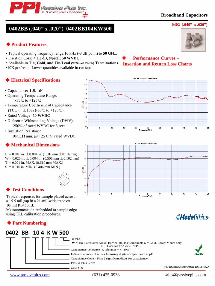
Frequency (GHz)
0 5 10 15 20 25 30 35 40 45 50
0402BB104 Return Loss (S11)
Mechanical Dimensions
Part Numbering
Test Conditions
0402BB (.040” x .020”) 0402BB104KW500
• Available in Tin, Gold, and Tin/Lead (90%Sn/10%Pb) Terminations
• Typical operating frequency range:16 kHz (-3 dB point) to 50 GHz;
0402 BB 10 4 K W 500 W = Tin Plated over Nickel Barrier (RoHS) Compliant; G = Gold, Epoxy Mount only
Capacitance Tolerance (K tolerance = +/-10%)
Indicates number of zeroes following digits of capacitance in pF
Case Size
Passive Plus Series
Capacitance Code – First 2 significant digits for capacitance
L= Tin/Lead (90%Sn/10%Pb)
• Insertion Loss: < 1.2 dB, typical; 50 WVDC;
PPI0402BB10450VData110518RevA
Typical responses for sample placed acrossa 15.5 mil gap in a 21-mil-wide trace on 10-mil R04350B.Measurements de-embedded to sample edge using TRL calibration procedures.
WVDC
Related Documents