Powerwarp Userguide FOR ARTPRO 8.6

Welcome message from author
This document is posted to help you gain knowledge. Please leave a comment to let me know what you think about it! Share it to your friends and learn new things together.
Transcript
Powerwarp UserguideFOR ARTPRO 8.6
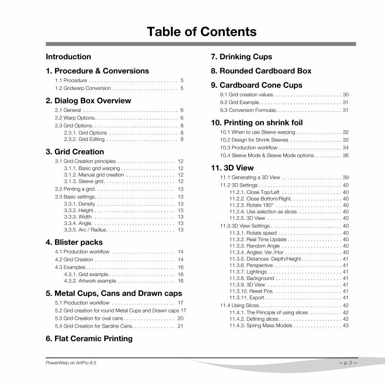
Table of Contents
Introduction
1. Procedure & Conversions1.1 Procedure . . . . . . . . . . . . . . . . . . . . . . . . . . . . . . . 5
1.2 Gridwarp Conversion . . . . . . . . . . . . . . . . . . . . . . . 5
2. Dialog Box Overview2.1 General . . . . . . . . . . . . . . . . . . . . . . . . . . . . . . . . . 6
2.2 Warp Options. . . . . . . . . . . . . . . . . . . . . . . . . . . . . 6
2.3 Grid Options. . . . . . . . . . . . . . . . . . . . . . . . . . . . . . 82.3.1. Grid Options . . . . . . . . . . . . . . . . . . . . . . . . 82.3.2. Grid Editing . . . . . . . . . . . . . . . . . . . . . . . . . 8
3. Grid Creation3.1 Grid Creation principles . . . . . . . . . . . . . . . . . . . . 12
3.1.1. Basic grid warping . . . . . . . . . . . . . . . . . . . 123.1.2. Manual grid creation . . . . . . . . . . . . . . . . . 123.1.3. Sleeve grid. . . . . . . . . . . . . . . . . . . . . . . . . 12
3.2 Printing a grid. . . . . . . . . . . . . . . . . . . . . . . . . . . . 13
3.3 Basic settings. . . . . . . . . . . . . . . . . . . . . . . . . . . . 133.3.1. Density . . . . . . . . . . . . . . . . . . . . . . . . . . . 133.3.2. Height.. . . . . . . . . . . . . . . . . . . . . . . . . . . . 133.3.3. Width. . . . . . . . . . . . . . . . . . . . . . . . . . . . . 133.3.4. Angle. . . . . . . . . . . . . . . . . . . . . . . . . . . . . 133.3.5. Arc / Radius. . . . . . . . . . . . . . . . . . . . . . . . 13
4. Blister packs4.1 Production workflow . . . . . . . . . . . . . . . . . . . . . . 14
4.2 Grid Creation . . . . . . . . . . . . . . . . . . . . . . . . . . . . 14
4.3 Examples . . . . . . . . . . . . . . . . . . . . . . . . . . . . . . . 164.3.1. Grid example . . . . . . . . . . . . . . . . . . . . . . . 164.3.2. Artwork example . . . . . . . . . . . . . . . . . . . . 16
5. Metal Cups, Cans and Drawn caps5.1 Production workflow . . . . . . . . . . . . . . . . . . . . . . 17
5.2 Grid creation for round Metal Cups and Drawn caps 17
5.3 Grid Creation for oval cans . . . . . . . . . . . . . . . . . . 20
5.4 Grid Creation for Sardine Cans. . . . . . . . . . . . . . . 21
6. Flat Ceramic Printing
PowerWarp on ArtPro 8.5
7. Drinking Cups
8. Rounded Cardboard Box
9. Cardboard Cone Cups9.1 Grid creation values. . . . . . . . . . . . . . . . . . . . . . . . 30
9.2 Grid Example. . . . . . . . . . . . . . . . . . . . . . . . . . . . . 31
9.3 Conversion Formulas. . . . . . . . . . . . . . . . . . . . . . . 31
10. Printing on shrink foil10.1 When to use Sleeve warping . . . . . . . . . . . . . . . . 32
10.2 Design for Shrink Sleeves . . . . . . . . . . . . . . . . . . 32
10.3 Production workflow . . . . . . . . . . . . . . . . . . . . . . 34
10.4 Sleeve Mode & Sleeve Mode options. . . . . . . . . . 36
11. 3D View11.1 Generating a 3D View . . . . . . . . . . . . . . . . . . . . . 39
11.2 3D Settings . . . . . . . . . . . . . . . . . . . . . . . . . . . . . 4011.2.1. Close Top/Left . . . . . . . . . . . . . . . . . . . . . 4011.2.2. Close Bottom/Right. . . . . . . . . . . . . . . . . . 4011.2.3. Rotate 180° . . . . . . . . . . . . . . . . . . . . . . . 4011.2.4. Use selection as slices . . . . . . . . . . . . . . . 4011.2.5. 3D View . . . . . . . . . . . . . . . . . . . . . . . . . . 40
11.3 3D View Settings . . . . . . . . . . . . . . . . . . . . . . . . . 4011.3.1. Rotate speed . . . . . . . . . . . . . . . . . . . . . . 4011.3.2. Real Time Update . . . . . . . . . . . . . . . . . . . 4011.3.3. Random Angle . . . . . . . . . . . . . . . . . . . . . 4011.3.4. Angles: Ver./Hor . . . . . . . . . . . . . . . . . . . . 4011.3.5. Distances: Depth/Height . . . . . . . . . . . . . . 4111.3.6. Perspective . . . . . . . . . . . . . . . . . . . . . . . . 4111.3.7. Lightings . . . . . . . . . . . . . . . . . . . . . . . . . . 4111.3.8. Background . . . . . . . . . . . . . . . . . . . . . . . 4111.3.9. 3D View . . . . . . . . . . . . . . . . . . . . . . . . . . 4111.3.10. Reset Pos. . . . . . . . . . . . . . . . . . . . . . . . 4111.3.11. Export . . . . . . . . . . . . . . . . . . . . . . . . . . . 41
11.4 Using Slices. . . . . . . . . . . . . . . . . . . . . . . . . . . . . 4211.4.1. The Principle of using slices . . . . . . . . . . . 4211.4.2. Defining slices . . . . . . . . . . . . . . . . . . . . . . 4211.4.3. Spring Mass Models . . . . . . . . . . . . . . . . . 43
— p. 2 —
12. Appendix12.1 Grid File Formats. . . . . . . . . . . . . . . . . . . . . . . . . 47
12.2 Definition of the Grid Coordinates . . . . . . . . . . . . 47
12.3 Grid Examples . . . . . . . . . . . . . . . . . . . . . . . . . . 48
12.4 Symmetrical grids in ArtPro. . . . . . . . . . . . . . . . . 50
12.5 Formulas of Link Values . . . . . . . . . . . . . . . . . . . 51
— p. 3 —
PowerWarp on ArtPro 8.5
Introduction
I. Definition
The Gridwarp module is a powerful and professional utility thatallows technical and free deformation of line-art, text and imag-es.
II. Copyright
Copyright © 1992 - 2008, Artwork Systems N.V. All rights re-served. Artwork Systems, ArtPro, Artworker and ArtPrinter aretrademarks of Artwork Systems N.V.These notes may not, in whole or in part, be reproduced in anyform, by print, photocopy, microfilm or any other means with-out prior written consent of Artwork Systems N.V.
III. PowerWarp Requirements
PowerWarp as described in this manual is an additional mod-ule of ArtPro. The Contone module or ArtColor module for im-age editing on pixel level is mandatory for warping non flat colorobjects.
IV. About this User Guide
This user guide is an addition to the ArtPro manual and de-scribes an optional module of ArtPro. The user guide is meantto be used as both a manual with a look-up information guideand a tutorial.The reader should have a basic knowledge of ArtPro and Art-Color.
PowerWarp on ArtPro 8.6
— p. 4 —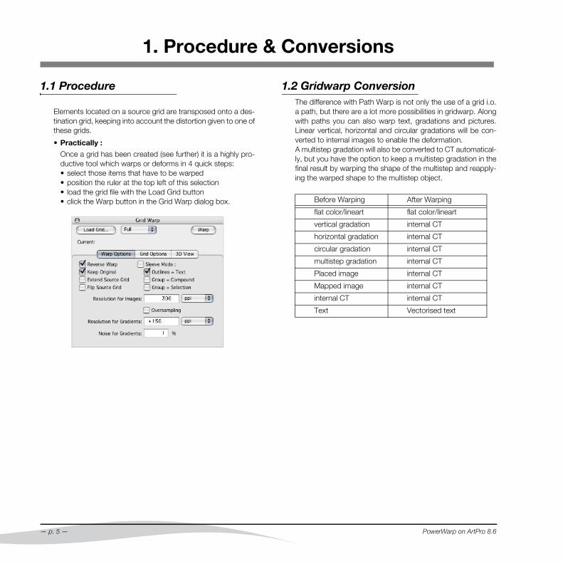
1. Procedure & Conversions
1.1 Procedure
Elements located on a source grid are transposed onto a des-tination grid, keeping into account the distortion given to one ofthese grids.
• Practically :
Once a grid has been created (see further) it is a highly pro-ductive tool which warps or deforms in 4 quick steps:• select those items that have to be warped• position the ruler at the top left of this selection• load the grid file with the Load Grid button• click the Warp button in the Grid Warp dialog box.
— p. 5 —
1.2 Gridwarp ConversionThe difference with Path Warp is not only the use of a grid i.o.a path, but there are a lot more possibilities in gridwarp. Alongwith paths you can also warp text, gradations and pictures.Linear vertical, horizontal and circular gradations will be con-verted to internal images to enable the deformation.A multistep gradation will also be converted to CT automatical-ly, but you have the option to keep a multistep gradation in thefinal result by warping the shape of the multistep and reapply-ing the warped shape to the multistep object.
Before Warping After Warping
flat color/lineart flat color/lineart
vertical gradation internal CT
horizontal gradation internal CT
circular gradation internal CT
multistep gradation internal CT
Placed image internal CT
Mapped image internal CT
internal CT internal CT
Text Vectorised text
PowerWarp on ArtPro 8.6
2. Dialog Box Overview
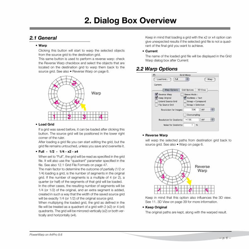
2.1 General• Warp
Clicking this button will start to warp the selected objectsfrom the source grid to the destination grid.This same button is used to perform a reverse warp: checkthe Reverse Warp checkbox and select the objects that arelocated on the destination grid to warp them back to thesource grid. See also • Reverse Warp on page 6.
• Load Grid
If a grid was saved before, it can be loaded after clicking thisbutton. The source grid will be positioned in the lower rightcorner of the ruler.After loading a grid file you can start editing the grid, but thegrid file remains untouched, unless you save and overwrite it.
• Full - 1/2 - 1/4 - x2 - x4
When set to “Full”, the grid will be read as specified in the gridfile. It will also use the “quadrant” parameter specified in thefile. See also 12.1 Grid File Formats on page 47.The main factor to determine the outcome of partially (1/2 or1/4) loading a grid, is the number of segments in the originalgrid. If the number of segments is a multiple of 4 (or 2), aquarter (or half) of the segments of that grid will be loaded. In the other cases, the resulting number of segments will be1/4 (or 1/2) of the original, and an extra segment is added,created in such a way that the width of the saved source gridwill be exactly 1/4 (or 1/2) of the original source grid. When multiplying the loaded grid, the grid as defined in thefile will be treated as a quadrant of a grid with 2 (x2) or 4 (x4)quadrants. The grid will be mirrored vertically (x2) or both ver-tically and horizontally (x4).
PowerWarp on ArtPro 8.6
Keep in mind that loading a grid with the x2 or x4 option cangive unexpected results if the selected grid file is not a quad-rant of the final grid you want to achieve.
• Current
The name of the loaded grid file will be displayed in the GridWarp dialog box after Current:
2.2 Warp Options
• Reverse Warp
will warp the selected paths from destination grid back tosource grid. See also • Warp on page 6.
Keep in mind that this option also influences the 3D view.See 11. 3D View on page 39 for more information.
• Keep Original
The original paths are kept, along with the warped result.
— p. 6 —
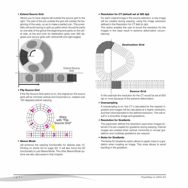
• Extend Source Grid
Allows you to have objects fall outside the source grid to theright. The part of the job outside the grid will overlap the be-ginning of the warp, so as to make a perfect join. This possi-bility will avoid having to split up paths which should lie partlyon one side of the grid at the beginning and partly on the oth-er side, at the end (only for destination grids over 360 de-grees and source grids with vertical left and right edges)
• Flip Source Grid
If the Flip Source Grid option is on, the original (on the sourcegrid) will be mirrored vertical and horizontal (i.e. rotated over180 degrees) before warping.
• Sleeve Mode
will enhance the warping functionality for sleeves (see 10.Printing on shrink foil on page 32). It will also force the 3Dfunctionality to use Sleeve Mode. The other Sleeve Mode op-tions are also discussed in that chapter.
Extend Source Grid
— p. 7 —
• Resolution for CT (default set at 300 dpi)
For each original image in the source selection, a new imagewill be created during warping, using the image resolutiondefined in the Resolution for CT field (in dpi).This option enables the user to boost the resolution for theimages in the warp result in extreme deformation circum-stances.
In this example the resolution for the CT would be set at 600dpi or more because of the extreme deformation.
• Oversampling
If oversampling is on, the CT’s calculated for the warped vi-gnettes and images will be calculated at a higher resolution,and then downsampled to the defined resolution. This will re-sult in a smoother image and gradations.
• Resolution for Gradients
This parameter defines the resolution used when images (in-ternal CTs) are created for gradients during warping. Internalimages are created when vertical, horizontal or circular gra-dations and multistep gradations are warped.
• Noise for Gradients
The Noise for Gradients option allows to apply noise to a gra-dation when creating an image. This noise allows to avoidbanding in the gradation.
PowerWarp on ArtPro 8.6

2.3 Grid Options
2.3.1 Grid Options• Create Grid
Will open a new dialog box for the creation of grids. (see 3.Grid Creation on page 12)
• Show Grid
this is a toggle to switch the grid visualization on or off.
• Save Grid
Enables you to save a grid you have created or changed asan ASCII text file. This is the grid format which can be loadedafterwards. Details about the structure of such grid file can be found inthe appendix.
• Full - 1/2 - 1/4
If a grid is saved, you can choose whether the grid should besaved completely (“Full”), or partially (1/2 or 1/4).The main factor to determine the outcome of partially savinga grid, is the number of segments in the original grid. If thenumber of segments is a multiple of 4 (or 2), a quarter (or half)of the segments of that grid will be saved. In the other cases,the resulting number of segments will be 1/4 (or 1/2) of theoriginal, and an extra segment is added, created in such away that the width of the saved source grid will be exactly 1/4 (or 1/2) of the original source grid. However, if you know that you will be working with Partialgrids in ArtPro, you should make sure that your grid is sym-
PowerWarp on ArtPro 8.6
metric. See 12.4 Symmetrical grids in ArtPro on page 50 formore info.
• Save Grid in Inch
Forces the Grid file to be saved with Inch as unit instead ofmm (see 12.1 Grid File Formats on page 47).
• Grid to Paths
Will make an exact replica of the grid as paths. The paths willbe put in a separate layer called ‘Grid’. If a stroke is createdbased on these paths, it enables you to print the grid.
• Erase Grid
Will erase the virtual grid; the paths in the ‘Grid’ layer will stay.
2.3.2 Grid Editing• What ?
A tool to edit either the source or destination grid on a man-ual basis. In the Which pop up menu you have the choice be-tween Source Grid and Destination grid. Only one can beedited at the time. Click the Modify Tool button and use thisnew cursor to select the grid points that have to be moved.• If you need to move one point at the time, it is very easy :by clicking on an unselected point you can drag it to the de-sired location without having to click a second time.• Several points can be moved by clicking and dragging arectangle that covers those points, or use the shift key andclick to select multiple points. To move: click on one of the selected points and drag in thedesired direction. The way several moving points behaveduring the movement depends on the How and Locality set-tings in the Modify Grid dialog box. These options are de-scribed next.In case of a misplacement you can always return one step byclicking the Undo button in the Modify grid dialog box.
• Which
The Which setting allows to define if you want to modify theSource grid or the Destination grid.
— p. 8 —
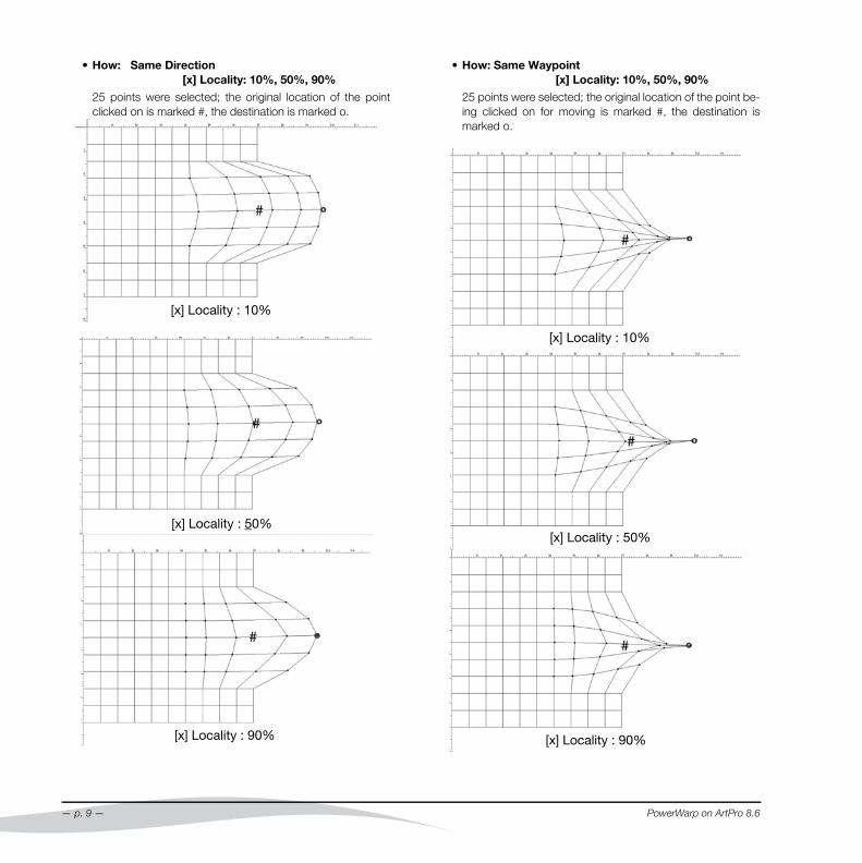
• How: Same Direction [x] Locality: 10%, 50%, 90%
25 points were selected; the original location of the pointclicked on is marked #, the destination is marked o.
[x] Locality : 10%
[x] Locality : 50%
[x] Locality : 90%
— p. 9 —
• How: Same Waypoint [x] Locality: 10%, 50%, 90%
25 points were selected; the original location of the point be-ing clicked on for moving is marked #, the destination ismarked o.
[x] Locality : 10%
[x] Locality : 50%
[x] Locality : 90%
PowerWarp on ArtPro 8.6
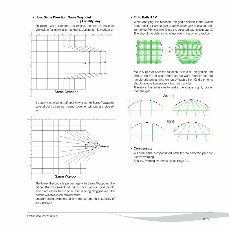
• How: Same Direction, Same Waypoint [ ] Locality: any
25 points were selected; the original location of the pointclicked on for moving is marked #, destination is marked o.
If Locality is switched off and How is set to Same Waypoint,several points can be moved together without any side ef-fect.
The lower the Locality percentage with Same Waypoint, thebigger the movement will be of most points. Grid pointswhich are closer to the point that is being dragged with thecursor will always be moved more.Locality being switched off is more extreme than Locality ofzero percent
Same Direction
Same Waypoint
PowerWarp on ArtPro 8.6
• Fit to Path H / V
When applying this function, the grid selected in the Whichpopup dialog (source grid or destination grid) is scaled hori-zontally (or Vertically) to fit into the selected path (see picture).The size of the cells is not influenced in the other direction.
Make sure that after the function, points of the grid do notend up on top of each other, as the warp module can nothandle grid points lying on top of each other. Grid elementsshould always be quadrangles, not triangles.Therefore it is advisable to make the shape slightly biggerthan the grid.
• Compensate
will create the compensated path for the selected path forSleeve warping. See 10. Printing on shrink foil on page 32.
Wrong
Right
— p. 10 —
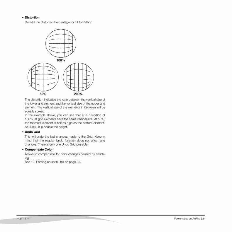
• Distortion
Defines the Distortion Percentage for Fit to Path V.
The distortion indicates the ratio between the vertical size ofthe lower grid element and the vertical size of the upper gridelement. The vertical size of the elements in between will beequally spread. In the example above, you can see that at a distortion of100%, all grid elements have the same vertical size. At 50%,the topmost element is half as high as the bottom element.At 200%, it is double the height.
• Undo Grid
This will undo the last changes made to the Grid. Keep inmind that the regular Undo function does not affect gridchanges. There is only one Undo Grid possible.
• Compensate Color
Allows to compensate for color changes caused by shrink-ing. See 10. Printing on shrink foil on page 32.
— p. 11 —
PowerWarp on ArtPro 8.6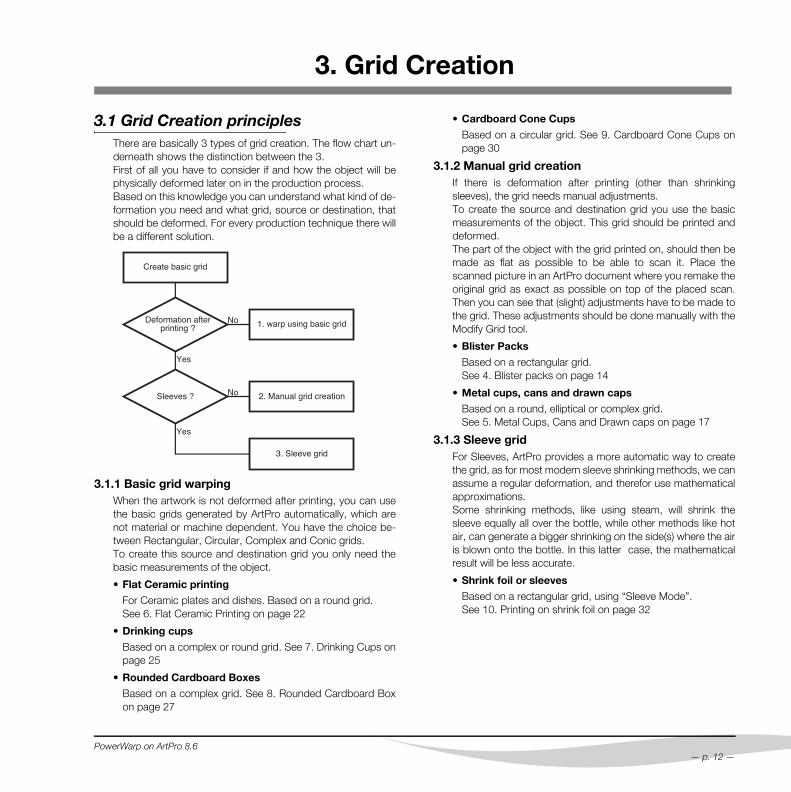
3. Grid Creation
3.1 Grid Creation principlesThere are basically 3 types of grid creation. The flow chart un-derneath shows the distinction between the 3.First of all you have to consider if and how the object will bephysically deformed later on in the production process.Based on this knowledge you can understand what kind of de-formation you need and what grid, source or destination, thatshould be deformed. For every production technique there willbe a different solution.
3.1.1 Basic grid warpingWhen the artwork is not deformed after printing, you can usethe basic grids generated by ArtPro automatically, which arenot material or machine dependent. You have the choice be-tween Rectangular, Circular, Complex and Conic grids.To create this source and destination grid you only need thebasic measurements of the object.
• Flat Ceramic printing
For Ceramic plates and dishes. Based on a round grid. See 6. Flat Ceramic Printing on page 22
• Drinking cups
Based on a complex or round grid. See 7. Drinking Cups onpage 25
• Rounded Cardboard Boxes
Based on a complex grid. See 8. Rounded Cardboard Boxon page 27
PowerWarp on ArtPro 8.6
• Cardboard Cone Cups
Based on a circular grid. See 9. Cardboard Cone Cups onpage 30
3.1.2 Manual grid creationIf there is deformation after printing (other than shrinkingsleeves), the grid needs manual adjustments.To create the source and destination grid you use the basicmeasurements of the object. This grid should be printed anddeformed.The part of the object with the grid printed on, should then bemade as flat as possible to be able to scan it. Place thescanned picture in an ArtPro document where you remake theoriginal grid as exact as possible on top of the placed scan.Then you can see that (slight) adjustments have to be made tothe grid. These adjustments should be done manually with theModify Grid tool.
• Blister Packs
Based on a rectangular grid. See 4. Blister packs on page 14
• Metal cups, cans and drawn caps
Based on a round, elliptical or complex grid. See 5. Metal Cups, Cans and Drawn caps on page 17
3.1.3 Sleeve gridFor Sleeves, ArtPro provides a more automatic way to createthe grid, as for most modern sleeve shrinking methods, we canassume a regular deformation, and therefor use mathematicalapproximations.Some shrinking methods, like using steam, will shrink thesleeve equally all over the bottle, while other methods like hotair, can generate a bigger shrinking on the side(s) where the airis blown onto the bottle. In this latter case, the mathematicalresult will be less accurate.
• Shrink foil or sleeves
Based on a rectangular grid, using “Sleeve Mode”. See 10. Printing on shrink foil on page 32
— p. 12 —
3.2 Printing a gridTo print a grid :
• Load a grid or create one• click the Grid To Paths button in the Gridwarp dialog• While the paths are still selected, use the Stroke function
(q - x - t) and the Paint Style (q - i) to define the line thick-ness and color.
• Print the job (q - p)
3.3 Basic settingsSome basic settings will be explained more into detail and ingeneral first, because they will be available in the Create Griddialog boxes of almost any grid type:
3.3.1 Densitythe value from this field defines the width and height of a singlecell from the grid. Such a square shaped, single cell is the basicpart of a grid and defines four points in the source grid that cor-respond with four points in the destination grid. Based on thesefour points, the item within the cell from the source grid will bedeformed, stretched or shrunk, when warped onto the destina-tion grid.The density has an influence on the speed of the warp calcula-tion. A Density ranging from 3mm to 5mm is advisable for mostgrids. Circular grids might need a lower density value if the seg-ments of the circular parts are not smooth enough.The Width and Height of the grid should be big enough to coverthe object, maybe even with a surplus of a few cells on certainsides.
3.3.2 Height.Measure the Height. Therefor do not measure the verticalheight if the object would have a sloping side, but place the rul-er on the object itself for measuring the slope side.
3.3.3 WidthThe value that has to be filled in for Width is not always exactlythe width, but depending on the object it could be the valuefrom the circumference or inner circle on the technical drawing.Since the basic element of the grid is one cell, it is recommend-ed to fill in values for both Height and Width which are dividableby the Density value. Otherwise the grid cells will be adapted insize automatically when the grid is created and this could beannoying for measuring afterwards.For sleeves, the grid should be the size of the sleeve, withoutthe overlap.
— p. 13 —
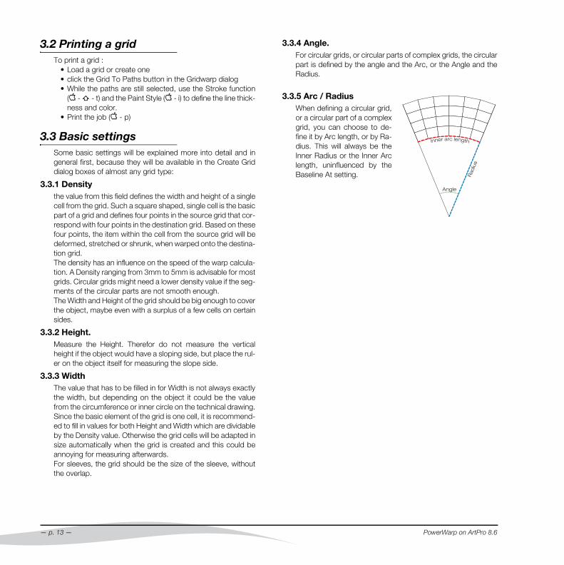
3.3.4 Angle.For circular grids, or circular parts of complex grids, the circularpart is defined by the angle and the Arc, or the Angle and theRadius.
3.3.5 Arc / RadiusWhen defining a circular grid,or a circular part of a complexgrid, you can choose to de-fine it by Arc length, or by Ra-dius. This will always be theInner Radius or the Inner Arclength, uninfluenced by theBaseline At setting.
PowerWarp on ArtPro 8.6
4. Blister packs
4.1 Production workflow- print the job on the flat substrate (plastic)- the substrate is then shaped (heated, stretched into a shape)- this gives the final result where the image should look normal(not affected by the shape of the object)With the warp module we will have to invert the deformationcaused by the machine that is stretching the substrate:
This explains why the grid we should change, is the sourcegrid, while the destination grid will have to remain unchanged,rectangular.
PowerWarp on ArtPro 8.6
4.2 Grid CreationFirst a basic grid has to bemade which consists of a rect-angular source and destina-tion grid. Therefor click on theCreate Grid button in the GridWarp dialog box. Then clickthe first icon: Rectangular. Three values have to be filledin:
• Density: 3 mm• Height: the example object is about 50 mm high, but we’ll
fill in 85 mm.• Width: the example object is about 35 mm wide, but we’ll
fill in 50 mm.
Rectangular will automatically make a rectangular source gridand a rectangular destination grid which are exactly the same.
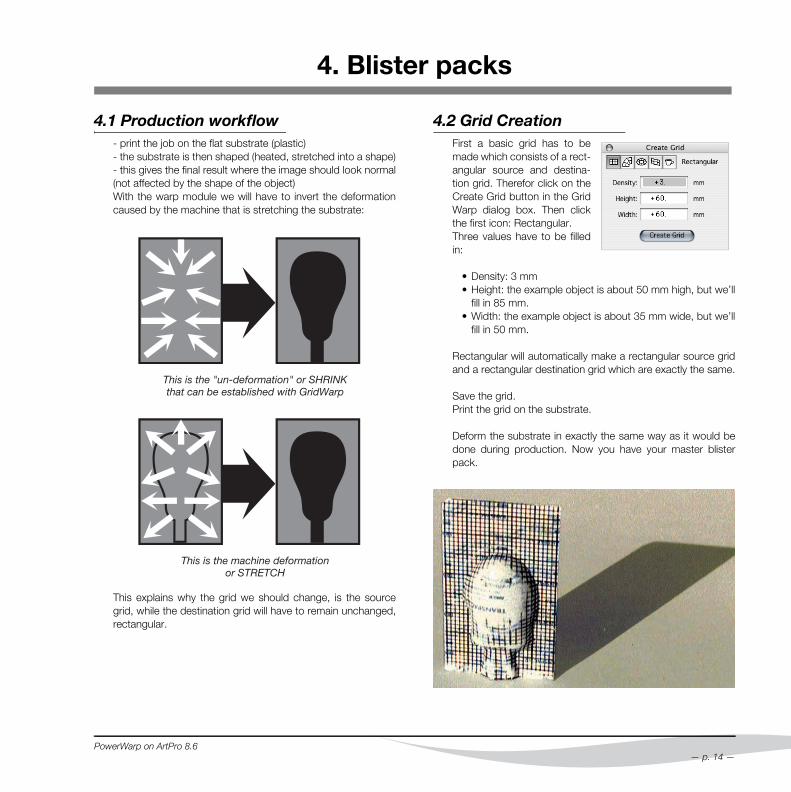
Save the grid.Print the grid on the substrate.
Deform the substrate in exactly the same way as it would bedone during production. Now you have your master blisterpack.
— p. 14 —
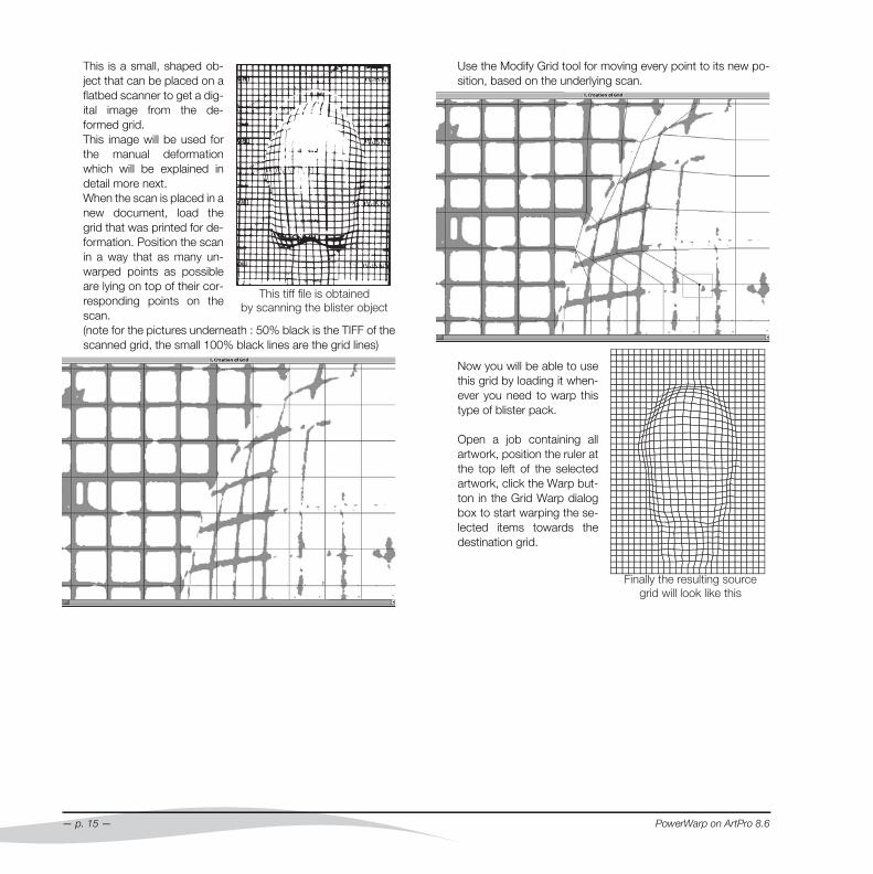
This is a small, shaped ob-ject that can be placed on aflatbed scanner to get a dig-ital image from the de-formed grid.This image will be used forthe manual deformationwhich will be explained indetail more next.When the scan is placed in anew document, load thegrid that was printed for de-formation. Position the scanin a way that as many un-warped points as possibleare lying on top of their cor-responding points on thescan. (note for the pictures underneath : 50% black is the TIFF of thescanned grid, the small 100% black lines are the grid lines)
— p. 15 —
Use the Modify Grid tool for moving every point to its new po-sition, based on the underlying scan.
Now you will be able to usethis grid by loading it when-ever you need to warp thistype of blister pack.
Open a job containing allartwork, position the ruler atthe top left of the selectedartwork, click the Warp but-ton in the Grid Warp dialogbox to start warping the se-lected items towards thedestination grid.
PowerWarp on ArtPro 8.6
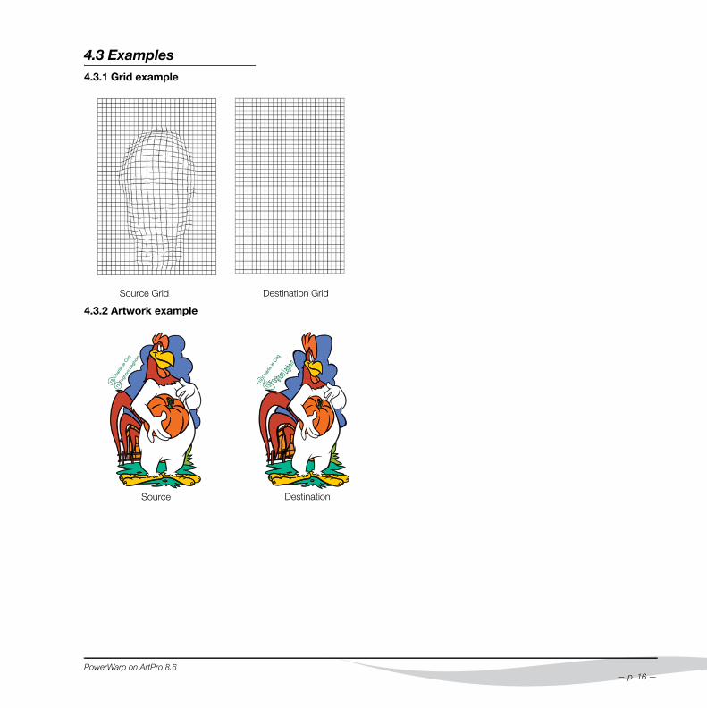
4.3 Examples4.3.1 Grid example
4.3.2 Artwork example
Source Grid Destination Grid
Source Destination
PowerWarp on ArtPro 8.6
— p. 16 —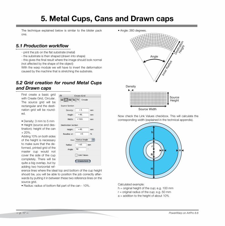
5. Metal Cups, Cans and Drawn caps
The technique explained below is similar to the blister packone.5.1 Production workflow- print the job on the flat substrate (metal)- the substrate is then shaped (drawn into shape)- this gives the final result where the image should look normal(not affected by the shape of the object)With the warp module we will have to invert the deformationcaused by the machine that is stretching the substrate.
5.2 Grid creation for round Metal Cupsand Drawn caps
First create a basic gridwith Create Grid, Circular.The source grid will berectangular and the desti-nation grid will be round-ed.
• Density: 3 mm to 5 mm• Height (source and des-tination): height of the can+ 20%.Adding 10% on both sidesof the height is necessaryto make sure that the de-formed, printed grid of themaster cup would notcover the side of the cupcompletely. There will bequite a big overlap, but byadding two horizontal ref-erence lines where the ideal top and bottom of the cup heightshould be, you will be able to position the job correctly after-wards by putting it in between these two reference lines on thesource grid.• Radius: radius of bottom flat part of the can - 10%.
— p. 17 —
• Angle: 360 degrees.
Now check the Link Values checkbox. This will calculate thecorresponding width (explained in the technical appendix).
Calculated example:h = original height of the cup; e.g. 100 mmr = original radius of the cup; e.g. 50 mma = addition to the height of about 10%
PowerWarp on ArtPro 8.6
H = newly calculated height = h + a + a = 120% he.g. 120 mm (based on the previous values)R = newly calculated radius = r - 10% he.g. 40 mm (based on the previous values)
Save the grid.
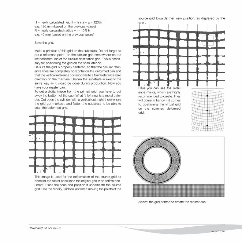
Make a printout of this grid on the substrate. Do not forget toput a reference point* on the circular grid somewhere on theleft horizontal line of the circular destination grid. This is neces-sary for positioning the grid on the scan later on.Be sure the grid is properly centered, so that the circular refer-ence lines are completely horizontal on the deformed can andthat the vertical reference corresponds to a fixed reference zerodirection on the machine. Deform the substrate in exactly thesame way as it would be done during production. Now youhave your master can.To get a digital image from the printed grid, you have to cutaway the bottom of the cup. What ’s left now is a metal cylin-der. Cut open the cylinder with a vertical cut, right there wherethe grid got marked*, and flatten the substrate to be able toscan the deformed grid.
This image is used for the deformation of the source grid asdone for the blister pack: load the original grid in an ArtPro doc-ument. Place the scan and position it underneath the sourcegrid. Use the Modify Grid tool and start moving the points of the
PowerWarp on ArtPro 8.6
source grid towards their new position, as displayed by thescan.
Here you can see the refer-ence marks, which are highlyrecommended to create. Theywill come in handy if it comesto positioning the virtual gridon the scanned deformedgrid.
Above: the grid printed to create the master can.
— p. 18 —

Below: the final grid with the adapted source grid.Notice that especially the vertical adjustments are of impor-tance because of the can drawing technique. Horizontalchanges are never to be registered: the can stretches in thevertical direction only. The horizontal deviation is negligible.
Below: output of the grid was made on film, then transmittedto the metal plate. From this plate a master cup can be drawn.
The distortion informa-tion must be digitized byadapting the virtualsource grid. If this wouldnot be done, the imagesand text on the sides ofthe cup would be wav-ing. See picture at theright.
— p. 19 —
Additional Examples :1. Printed plates, ready for drawing the cans out of
2. Plate with cup ; barcode on bottom
3. Plate with cup ; barcode on side. Undistorted picture andtext on the bottom
PowerWarp on ArtPro 8.6
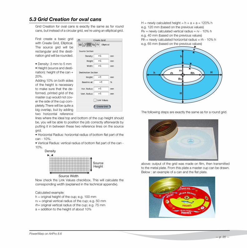
5.3 Grid Creation for oval cansGrid Creation for oval cans is exactly the same as for roundcans, but instead of a circular grid, we’re using an elliptical grid.
First create a basic gridwith Create Grid, Elliptical.The source grid will berectangular and the desti-nation grid will be rounded.
• Density: 3 mm to 5 mm• Height (source and desti-nation): height of the can +20%.Adding 10% on both sidesof the height is necessaryto make sure that the de-formed, printed grid of themaster cup would not cov-er the side of the cup com-pletely.There will be quite abig overlap, but by addingtwo horizontal referencelines where the ideal top and bottom of the cup height shouldbe, you will be able to position the job correctly afterwards byputting it in between these two reference lines on the sourcegrid.• Horizontal Radius: horizontal radius of bottom flat part of thecan - 10%.• Vertical Radius: vertical radius of bottom flat part of the can -10%.
Now check the Link Values checkbox. This will calculate thecorresponding width (explained in the technical appendix).
Calculated example:h = original height of the cup; e.g. 100 mmrv = original vertical radius of the cup; e.g. 50 mmrh= original vertical radius of the cup; e.g. 75 mma = addition to the height of about 10%
PowerWarp on ArtPro 8.6
H = newly calculated height = h + a + a = 120% he.g. 120 mm (based on the previous values)Rv = newly calculated vertical radius = rv - 10% he.g. 40 mm (based on the previous values)Rh = newly calculated horizontal radius = rh - 10% he.g. 65 mm (based on the previous values)
The following steps are exactly the same as for a round grid.
above: output of the grid was made on film, then transmittedto the metal plate. From this plate a master cup can be drawn.Below : an example of a can and the flat plate.
— p. 20 —
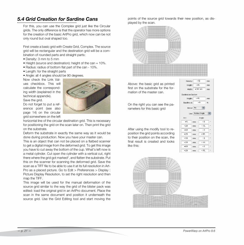
5.4 Grid Creation for Sardine CansFor this, you can use the Complex grid just like the Circulargrids. The only difference is that the operator has more optionsfor the creation of the basic ArtPro grid, which now can be notonly round but oval shaped too.
First create a basic grid with Create Grid, Complex. The sourcegrid will be rectangular and the destination grid will be a com-bination of rounded parts and straight parts:• Density: 3 mm to 5 mm• Height (source and destination): height of the can + 10%.• Radius: radius of bottom flat part of the can - 10%.• Length: for the straight parts• Angle: all 4 angles should be 90 degrees.Now check the Link Val-ues checkbox. This willcalculate the correspond-ing width (explained in thetechnical appendix).Save the grid.Do not forget to put a ref-erence point (see alsopage 14) on the circulargrid somewhere on the lefthorizontal line of the circular destination grid. This is necessaryfor positioning the grid on the scan later on. Then print the gridon the substrate.Deform the substrate in exactly the same way as it would bedone during production. Now you have your master can.This is an object that can not be placed on a flatbed scannerto get a digital image from the deformed grid. To get this imageyou have to cut away the bottom of the cup. What’s left now isa metal cylinder. Cut open the cylinder with a vertical cut, rightthere where the grid got marked*, and flatten the substrate. Putthis on the scanner for scanning the deformed grid. Save thescan as a TIFF file to be able to use it at its full resolution in Art-Pro as a placed picture. Go to Edit > Preferences > Display :Picture Display Resolution, to set the right resolution and thenmap the TIFF.This image will be used for the manual deformation of thesource grid similar to the way the grid of the blister pack wasedited: load the original grid in an ArtPro document. Place thescan in the same document and position it underneath thesource grid. Use the Grid Editing tool and start moving the
— p. 21 —
points of the source grid towards their new position, as dis-played by the scan.
Above: the basic grid as printedfirst on the substrate for the for-mation of the master can.
On the right you can see the pa-rameters for this basic grid
After using the modify tool to re-position the grid points accordingto their position on the scan, thefinal result is created and lookslike this:
PowerWarp on ArtPro 8.6
6. Flat Ceramic Printing
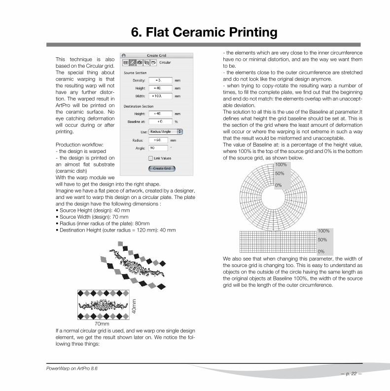
This technique is alsobased on the Circular grid.The special thing aboutceramic warping is thatthe resulting warp will nothave any further distor-tion. The warped result inArtPro will be printed onthe ceramic surface. Noeye catching deformationwill occur during or afterprinting.
Production workflow:- the design is warped- the design is printed onan almost flat substrate(ceramic dish)With the warp module wewill have to get the design into the right shape.Imagine we have a flat piece of artwork, created by a designer,and we want to warp this design on a circular plate. The plateand the design have the following dimensions :• Source Height (design): 40 mm• Source Width (design): 70 mm• Radius (inner radius of the plate): 80mm• Destination Height (outer radius = 120 mm): 40 mm
If a normal circular grid is used, and we warp one single designelement, we get the result shown later on. We notice the fol-lowing three things:
70mm
40m
m
PowerWarp on ArtPro 8.6
- the elements which are very close to the inner circumferencehave no or minimal distortion, and are the way we want themto be.- the elements close to the outer circumference are stretchedand do not look like the original design anymore.- when trying to copy-rotate the resulting warp a number oftimes, to fill the complete plate, we find out that the beginningand end do not match: the elements overlap with an unaccept-able deviation.The solution to all this is the use of the Baseline at parameter.Itdefines what height the grid baseline should be set at. This isthe section of the grid where the least amount of deformationwill occur or where the warping is not extreme in such a waythat the result would be misformed and unacceptable.The value of Baseline at: is a percentage of the height value,where 100% is the top of the source grid and 0% is the bottomof the source grid, as shown below.
We also see that when changing this parameter, the width ofthe source grid is changing too. This is easy to understand asobjects on the outside of the circle having the same length asthe original objects at Baseline 100%, the width of the sourcegrid will be the length of the outer circumference.
100%
50%
0%
100%
50%
0%
— p. 22 —
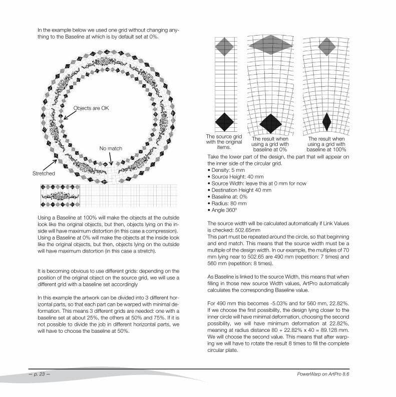
In the example below we used one grid without changing any-thing to the Baseline at which is by default set at 0%.
Using a Baseline at 100% will make the objects at the outsidelook like the original objects, but then, objects lying on the in-side will have maximum distortion (in this case a compression). Using a Baseline at 0% will make the objects at the inside looklike the original objects, but then, objects lying on the outsidewill have maximum distortion (in this case a stretch).
It is becoming obvious to use different grids: depending on theposition of the original object on the source grid, we will use adifferent grid with a baseline set accordingly
In this example the artwork can be divided into 3 different hor-izontal parts, so that each part can be warped with minimal de-formation. This means 3 different grids are needed: one with abaseline set at about 25%, the others at 50% and 75%. If it isnot possible to divide the job in different horizontal parts, wewill have to choose the baseline at 50%.
Objects are OK
Stretched
No match
— p. 23 —
Take the lower part of the design, the part that will appear onthe inner side of the circular grid.• Density: 5 mm• Source Height: 40 mm• Source Width: leave this at 0 mm for now• Destination Height 40 mm• Baseline at: 0%• Radius: 80 mm• Angle 360º
The source width will be calculated automatically if Link Valuesis checked: 502.65mmThis part must be repeated around the circle, so that beginningand end match. This means that the source width must be amultiple of the design width. In our example, the multiples of 70mm lying near to 502.65 are 490 mm (repetition: 7 times) and560 mm (repetition: 8 times).
As Baseline is linked to the source Width, this means that whenfilling in those new source Width values, ArtPro automaticallycalculates the corresponding Baseline value.
For 490 mm this becomes -5.03% and for 560 mm, 22.82%.If we choose the first possibility, the design lying closer to theinner circle will have minimal deformation, choosing the secondpossibility, we will have minimum deformation at 22.82%,meaning at radius distance 80 + 22.82% x 40 = 89.128 mm.We will choose the second value. This means that after warp-ing we will have to rotate the result 8 times to fill the completecircular plate.
The source gridwith the original
items.
The result whenusing a grid withbaseline at 0%
The result whenusing a grid withbaseline at 100%
PowerWarp on ArtPro 8.6
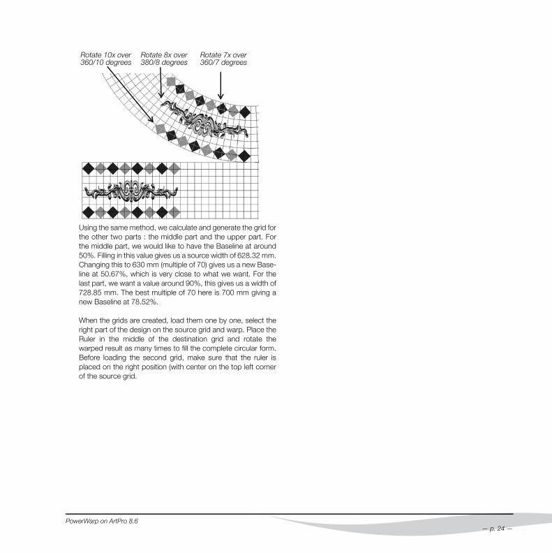
Using the same method, we calculate and generate the grid forthe other two parts : the middle part and the upper part. Forthe middle part, we would like to have the Baseline at around50%. Filling in this value gives us a source width of 628.32 mm.Changing this to 630 mm (multiple of 70) gives us a new Base-line at 50.67%, which is very close to what we want. For thelast part, we want a value around 90%, this gives us a width of728.85 mm. The best multiple of 70 here is 700 mm giving anew Baseline at 78.52%.
When the grids are created, load them one by one, select theright part of the design on the source grid and warp. Place theRuler in the middle of the destination grid and rotate thewarped result as many times to fill the complete circular form.Before loading the second grid, make sure that the ruler isplaced on the right position (with center on the top left cornerof the source grid.
Rotate 10x over360/10 degrees
Rotate 8x over380/8 degrees
Rotate 7x over360/7 degrees
PowerWarp on ArtPro 8.6
— p. 24 —
7. Drinking Cups
There is more than one technique for printing drinking cups. Itmostly depends on the material that is being used for the cre-ation of the cups: cardboard which is printed flat and is foldedafterwards into the right shape, and plastic cups which are be-ing printed after the cups are shaped. This last technique isdone by printing all colors on one rubber sloping block whichis located in the printing system. The cups are then rolledagainst this rubber block letting the ink being transferred uponthe plastic surface.The cardboard drinking cup workflow is explained in more de-tail below.
Production workflow:- print the job on the flat substrate (cardboard)- the substrate is then shaped (folded into shape)- this gives the final result where the image should look normal(not affected by the shape of the object)
No stretching or shrinking of the substrate occurs during thisprocedure: the warp module is used to get the design in theright shape of the unfolded object.
— p. 25 —
First create a basic grid with Create Grid, Conic.
The source grid will be rectangular and the destination grid willbe a segment of a rounded grid:
• Density: 3 mm to 5 mm• Height: do not measure the vertical height of the object, butplace the ruler on the object itself for measuring the slopingside.• Larger diameter: top diameter of the cup.• Smaller diameter: bottom diameter of the cup.
PowerWarp on ArtPro 8.6
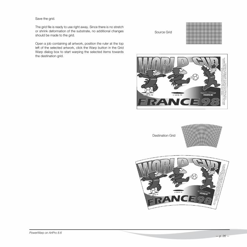
Save the grid.
The grid file is ready to use right away. Since there is no stretchor shrink deformation of the substrate, no additional changesshould be made to the grid.
Open a job containing all artwork, position the ruler at the topleft of the selected artwork, click the Warp button in the GridWarp dialog box to start warping the selected items towardsthe destination grid.
PowerWarp on ArtPro 8.6
Destination Grid
Source Grid
— p. 26 —
8. Rounded Cardboard Box
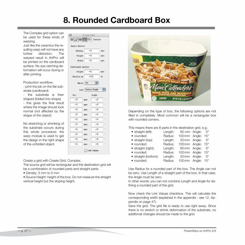
The Complex grid option canbe used for these kinds ofwarping.Just like the ceramics the re-sulting warp will not have anyfurther distortion. Thewarped result in ArtPro willbe printed on the cardboardsurface. No eye catching de-formation will occur during orafter printing.Production workflow:- print the job on the flat sub-strate (cardboard)- the substrate is thenshaped (folded into shape)- this gives the final resultwhere the image should looknormal (not affected by theshape of the object)
No stretching or shrinking ofthe substrate occurs duringthis whole procedure: thewarp module is used to getthe design in the right shapeof the unfolded object.
Create a grid with Create Grid, Complex.The source grid will be rectangular and the destination grid willbe a combination of rounded parts and straight parts.• Density: 3 mm to 5 mm• Source Height: height of the box. Do not measure the straightvertical height but the sloping height.
— p. 27 —
Depending on the type of box, the following options are notfilled in completely. Most common will be a rectangular boxwith rounded corners.
This means there are 8 parts in the destination grid, e.g.:• straight (left): Length: 60 mm Angle: 0°• rounded: Radius: 100 mm Angle: 15°• straight (top): Length: 20 mm Angle: 0°• rounded: Radius: 100 mm Angle: 15°• straight (right): Length: 60 mm Angle: 0°• rounded: Radius: 100 mm Angle: 15°• straight (bottom): Length: 20 mm Angle: 0°• rounded: Radius: 100 mm Angle: 15°
Use Radius for a rounded part of the box. The Angle can notbe zero. Use Length of a straight part of the box. In that case,the Angle must be zero.In other words: you can not combine Length and Angle for de-fining a rounded part of the grid.
Now check the Link Values checkbox. This will calculate thecorresponding width (explained in the appendix : see 12. Ap-pendix on page 47).Save the grid. The grid file is ready to use right away. Sincethere is no stretch or shrink deformation of the substrate, noadditional changes should be made to the grid.
PowerWarp on ArtPro 8.6
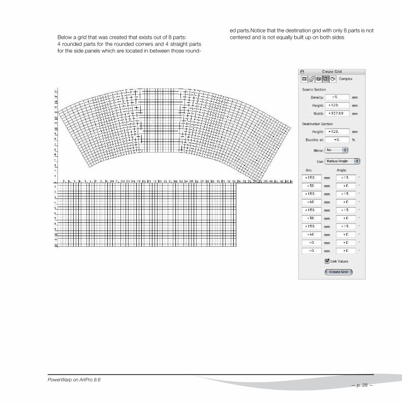
Below a grid that was created that exists out of 8 parts:4 rounded parts for the rounded corners and 4 straight partsfor the side panels which are located in between those round-
PowerWarp on ArtPro 8.6
ed parts.Notice that the destination grid with only 8 parts is notcentered and is not equally built up on both sides
— p. 28 —
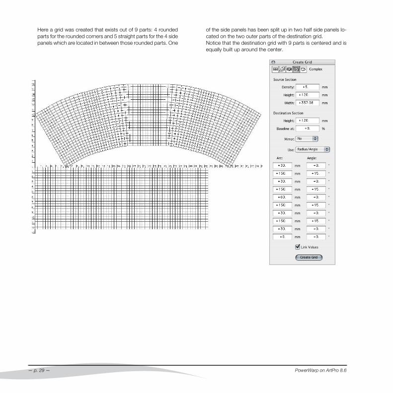
Here a grid was created that exists out of 9 parts: 4 roundedparts for the rounded corners and 5 straight parts for the 4 sidepanels which are located in between those rounded parts. One
— p. 29 —
of the side panels has been split up in two half side panels lo-cated on the two outer parts of the destination grid.Notice that the destination grid with 9 parts is centered and isequally built up around the center.
PowerWarp on ArtPro 8.6

9. Cardboard Cone Cups
Cardboard Cone Cupscan be warped using acircular gridJust like the ceramicsthe resulting warp willnot have any further dis-tortion. The warped re-sult in ArtPro will beprinted on the card-board surface. No eyecatching deformationwill occur during or afterprinting.One of the most impor-tant things to keep inmind when creating agrid for Cone Cupwarping, is that the grid-warp module can onlyhandle quadrangle gridelements. Therefor, thebottom of the grid will be stripped, to avoid the creation of tri-angular grid elements. However, this will not influence the finalresult, if the user extends the artwork downwards.The Height used for the grid (Height) will be the length of theside of the cone cup (H) minus the length of the stripped part (h)PowerWarp on ArtPro 8.6
9.1 Grid creation valuesAll values necessary for the creation of the correct grid, isbased on only 2 parameters : the length of the side of the conecup (H), and the angle ( α ). If any other pair of values is given,these can be used to calculate the side of the cone and the an-gle. For some conversion formulas, see 9.3 on page 31.
• Density
It is highly recommended touse 0.5 mm.
• Source Height
As explained above, theHeight for the grid will be thetotal height of the cup minusthe stripped part.So Height = H - héThe height of the strippedpart (h) is defined by thelength of the Arc (see below)and the Angle, using the fol-lowing formula:
or in another form :
• Source Width
The value for width does not matter, as it has no influence onthe grid
• Destination Height
The same as the Source Height
• Baseline At
should be set at 100% to start (see also 6. Flat Ceramic Print-ing on page 22)
• Arc/Angle
Arc = 40 x Densitythe Angle is the angle ( α )
• Link Values
should be OFF
h 40 Density 180××Angle π×
------------------------------------------------=
h Density 2.292×Angle
----------------------------------------=
— p. 30 —
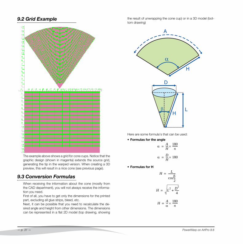
9.2 Grid Example
The example above shows a grid for cone cups. Notice that thegraphic design (shown in magenta) extends the source grid,generating the tip in the warped version. When creating a 3Dpreview, this will result in a nice cone (see previous page).
9.3 Conversion FormulasWhen receiving the information about the cone (mostly fromthe CAD department), you will not always receive the informa-tion you need. First of all, you have to get only the dimensions for the printedpart, excluding all glue strips, bleed, etc.Next, it can be possible that you need to recalculate the de-sired angle and height from other dimensions. The dimensionscan be represented in a flat 2D model (top drawing, showing
— p. 31 —
the result of unwrapping the cone cup) or in a 3D model (bot-tom drawing)
Here are some formula’s that can be used:
• Formulas for the angle
• Formulas for H
α AH---- 180
π---------×=
α DH---- 180×=
H Lβ2---cos
------------=
H L2 D2
4------+=
H Aα--- 180
π---------×=
PowerWarp on ArtPro 8.6
10. Printing on shrink foil
10.1 When to use Sleeve warpingThe method for shrink sleeves is only valid for circular, symetricbottles. It is based on the assumption that the shrinking is doneequally all around the bottle. As explained in 3.1.3 Sleeve gridon page 12, this can depend on the shrinking method.For non circular but symetric bottles, the same method as forcircular bottles can be used, but the accuracy can not be guar-anteed. Again, it will work if the shrinking is equal all around thebottle, but for non circular shapes this is less obvious.For non circular, non symetric shapes, it is not advised to usesleeve warping, as the result would be unpredictable
10.2 Design for Shrink Sleeves• Why compensate graphics for sleeves
A small example will illustrate why pre-press specialists mustpre-compensate for shrink. Let’s imagine we will print around apple on a sleeve of a bottle of apple juice. When theapple is positioned on the sleeve where the shrink is relativelysmall e.g. in the middle, the apple will retain its round shape(more or less). When you print the apple somewhere on thetop of the bottle - where the shrink is much bigger - the applewill shrink differently in different directions depending on theshape of the bottle and the apple will become more egg-shaped. Anyone can understand that if you compensate forthis distortion, that is when you print an egg-shaped apple sothat after shrink it becomes round again, the sleeve will lookmuch better.
• The Design:
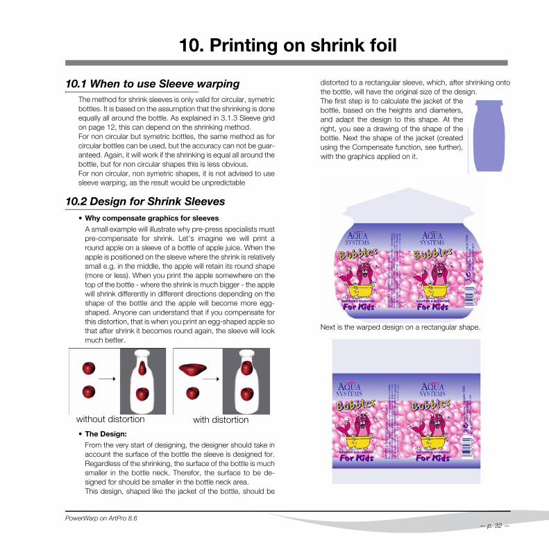
From the very start of designing, the designer should take inaccount the surface of the bottle the sleeve is designed for.Regardless of the shrinking, the surface of the bottle is muchsmaller in the bottle neck. Therefor, the surface to be de-signed for should be smaller in the bottle neck area.This design, shaped like the jacket of the bottle, should be
without distortion with distortion
PowerWarp on ArtPro 8.6
distorted to a rectangular sleeve, which, after shrinking ontothe bottle, will have the original size of the design.The first step is to calculate the jacket of thebottle, based on the heights and diameters,and adapt the design to this shape. At theright, you see a drawing of the shape of thebottle. Next the shape of the jacket (createdusing the Compensate function, see further),with the graphics applied on it.
Next is the warped design on a rectangular shape.
— p. 32 —
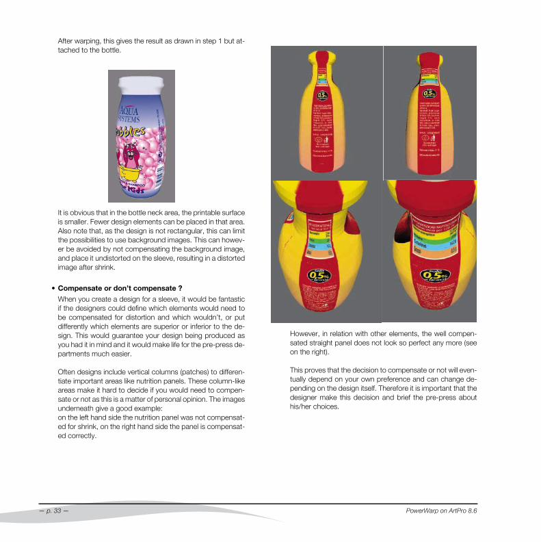
After warping, this gives the result as drawn in step 1 but at-tached to the bottle.
It is obvious that in the bottle neck area, the printable surfaceis smaller. Fewer design elements can be placed in that area.Also note that, as the design is not rectangular, this can limitthe possibilities to use background images. This can howev-er be avoided by not compensating the background image,and place it undistorted on the sleeve, resulting in a distortedimage after shrink.
• Compensate or don’t compensate ?
When you create a design for a sleeve, it would be fantasticif the designers could define which elements would need tobe compensated for distortion and which wouldn’t, or putdifferently which elements are superior or inferior to the de-sign. This would guarantee your design being produced asyou had it in mind and it would make life for the pre-press de-partments much easier.
Often designs include vertical columns (patches) to differen-tiate important areas like nutrition panels. These column-likeareas make it hard to decide if you would need to compen-sate or not as this is a matter of personal opinion. The imagesunderneath give a good example: on the left hand side the nutrition panel was not compensat-ed for shrink, on the right hand side the panel is compensat-ed correctly.
— p. 33 —
However, in relation with other elements, the well compen-sated straight panel does not look so perfect any more (seeon the right).
This proves that the decision to compensate or not will even-tually depend on your own preference and can change de-pending on the design itself. Therefore it is important that thedesigner make this decision and brief the pre-press abouthis/her choices.
PowerWarp on ArtPro 8.6
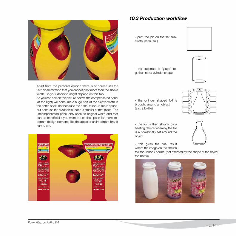
Apart from the personal opinion there is of course still thetechnical limitation that you cannot print more than the sleevewidth. So your decision might depend on this too.As you can see on the picture below, the compensated panel(at the right) will consume a huge part of the sleeve width inthe bottle neck, not because the panel takes up more space,but because the available surface is smaller at that place. Theuncompensated panel only uses its original width and thatcan be beneficial if you want to use the space for more im-portant design elements like the apple or an important brandname, etc.
PowerWarp on ArtPro 8.6
10.3 Production workflow
- print the job on the flat sub-strate (shrink foil)
- the substrate is “glued” to-gether into a cylinder shape
- the cylinder shaped foil isbrought around an object (e.g. a bottle)
- the foil is then shrunk by aheating device whereby the foilis automatically set around theobject
- this gives the final resultwhere the image on the shrunkfoil should look normal (not affected by the shape of the object:the bottle)
— p. 34 —
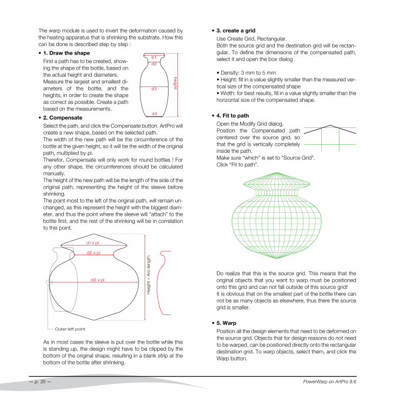
The warp module is used to invert the deformation caused bythe heating apparatus that is shrinking the substrate. How thiscan be done is described step by step :
• 1. Draw the shape
First a path has to be created, show-ing the shape of the bottle, based onthe actual height and diameters.Measure the largest and smallest di-ameters of the bottle, and theheights, in order to create the shapeas correct as possible. Create a pathbased on the measurements.
• 2. Compensate
Select the path, and click the Compensate button. ArtPro willcreate a new shape, based on the selected path.The width of the new path will be the circumference of thebottle at the given height, so it will be the width of the originalpath, multiplied by pi.Therefor, Compensate will only work for round bottles ! Forany other shape, the circumferences should be calculatedmanually.The height of the new path will be the length of the side of theoriginal path, representing the height of the sleeve beforeshrinking.The point most to the left of the original path, will remain un-changed, as this represent the height with the biggest diam-eter, and thus the point where the sleeve will “attach” to thebottle first, and the rest of the shrinking will be in correlationto this point.
As in most cases the sleeve is put over the bottle while thisis standing up, the design might have to be clipped by thebottom of the original shape, resulting in a blank strip at thebottom of the bottle after shrinking.
d1
d2
d3
d4
he
igh
t
— p. 35 —
• 3. create a grid
Use Create Grid, Rectangular.Both the source grid and the destination grid will be rectan-gular. To define the dimensions of the compensated path,select it and open the box dialog
• Density: 3 mm to 5 mm• Height: fill in a value slightly smaller than the measured ver-tical size of the compensated shape• Width: for best results, fill in a value slightly smaller than thehorizontal size of the compensated shape.
• 4. Fit to path
Open the Modify Grid dialog.Position the Compensated pathcentered over the source grid, sothat the grid is vertically completelyinside the path.Make sure “which” is set to “Source Grid”.Click “Fit to path”.
Do realize that this is the source grid. This means that theoriginal objects that you want to warp must be positionedonto this grid and can not fall outside of this source grid!It is obvious that on the smallest part of the bottle there cannot be as many objects as elsewhere, thus there the sourcegrid is smaller.
• 5. Warp
Position all the design elements that need to be deformed onthe source grid. Objects that for design reasons do not needto be warped, can be positioned directly onto the rectangulardestination grid. To warp objects, select them, and click theWarp button.
PowerWarp on ArtPro 8.6
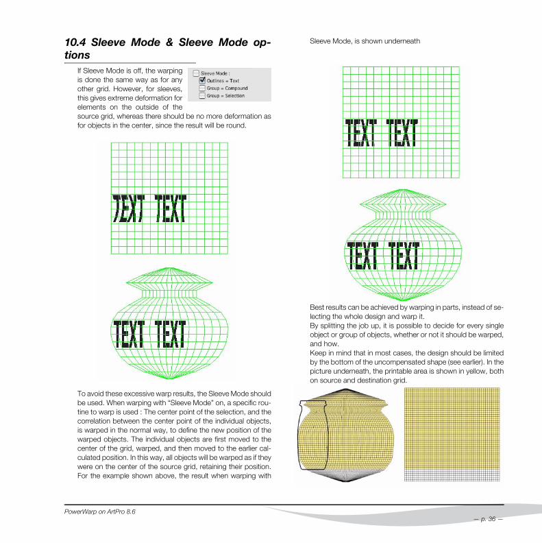
10.4 Sleeve Mode & Sleeve Mode op-tions
If Sleeve Mode is off, the warpingis done the same way as for anyother grid. However, for sleeves,this gives extreme deformation forelements on the outside of thesource grid, whereas there should be no more deformation asfor objects in the center, since the result will be round.
To avoid these excessive warp results, the Sleeve Mode shouldbe used. When warping with “Sleeve Mode” on, a specific rou-tine to warp is used : The center point of the selection, and thecorrelation between the center point of the individual objects,is warped in the normal way, to define the new position of thewarped objects. The individual objects are first moved to thecenter of the grid, warped, and then moved to the earlier cal-culated position. In this way, all objects will be warped as if theywere on the center of the source grid, retaining their position.For the example shown above, the result when warping with
PowerWarp on ArtPro 8.6
Sleeve Mode, is shown underneath
Best results can be achieved by warping in parts, instead of se-lecting the whole design and warp it. By splitting the job up, it is possible to decide for every singleobject or group of objects, whether or not it should be warped,and how.Keep in mind that in most cases, the design should be limitedby the bottom of the uncompensated shape (see earlier). In thepicture underneath, the printable area is shown in yellow, bothon source and destination grid.
— p. 36 —
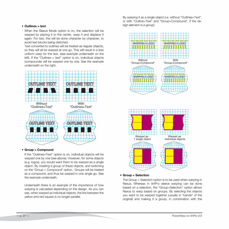
• Outlines = text
When the Sleeve Mode option is on, the selection will bewarped by placing it to the center, warp it and displace itagain. For text, this will be done character by character, toavoid text blocks being distorted.Text converted to outlines will be treated as regular objects,so they will all be warped at one go. This will result in a lessuniform warp for the text. (see example underneath on theleft). If the “Outlines = text” option is on, individual objects(compounds) will be warped one by one. See the exampleunderneath on the right.
• Group = Compound
If the “Outlines=Text” option is on, individual objects will bewarped one by one (see above). However, for some objects(e.g. logos), you would want them to be warped as a singleobject. By creating a group of these objects, and switchingon the “Group = Compound” option, Groups will be treatedas a compound, and thus be warped in one single go. Seethe example underneath.
Underneath there is an example of the importance of howwarping is calculated depending on the design. As you cansee, when warped as individual objects, the line between theyellow and red square is no longer parallel.
— p. 37 —
By warping it as a single object (i.e. without “Outlines=Text”,or with “Outline=Text” and “Group=Compound”, if the de-sign element is a group).
• Group = Selection
The Group = Selection option is to be used when warping inNexus. Whereas in ArtPro sleeve warping can be donebased on a selection, the “Group=Selection” option allowsNexus to warp based on groups. By selecting the objectsyou want to be warped together (usually in “bands” of theoriginal) and making it a group, in combination with the
PowerWarp on ArtPro 8.6

“Group = Selection” option in Nexus, you can get the sameresult as selecting and warping in ArtPro.
PowerWarp on ArtPro 8.6
— p. 38 —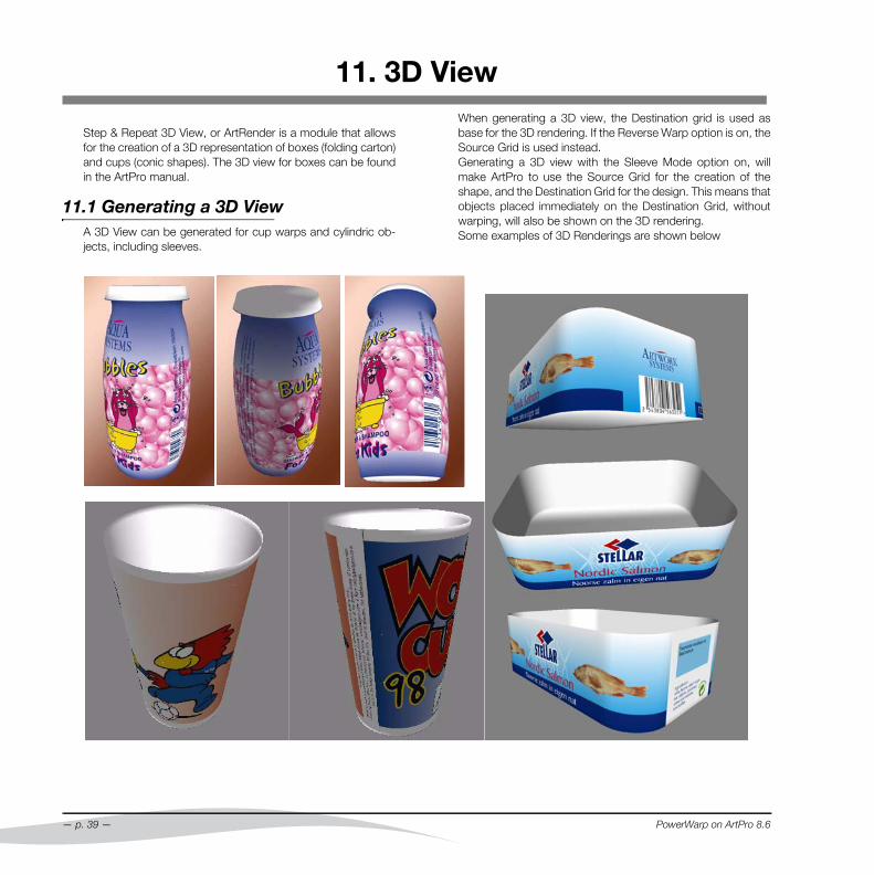
11. 3D View
Step & Repeat 3D View, or ArtRender is a module that allowsfor the creation of a 3D representation of boxes (folding carton)and cups (conic shapes). The 3D view for boxes can be foundin the ArtPro manual.
11.1 Generating a 3D ViewA 3D View can be generated for cup warps and cylindric ob-jects, including sleeves.
— p. 39 —
When generating a 3D view, the Destination grid is used asbase for the 3D rendering. If the Reverse Warp option is on, theSource Grid is used instead.Generating a 3D view with the Sleeve Mode option on, willmake ArtPro to use the Source Grid for the creation of theshape, and the Destination Grid for the design. This means thatobjects placed immediately on the Destination Grid, withoutwarping, will also be shown on the 3D rendering.Some examples of 3D Renderings are shown below
PowerWarp on ArtPro 8.6
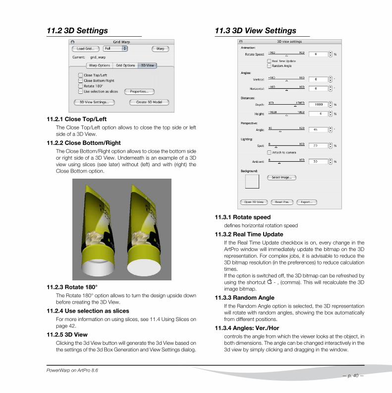
11.2 3D Settings
11.2.1 Close Top/LeftThe Close Top/Left option allows to close the top side or leftside of a 3D View.
11.2.2 Close Bottom/RightThe Close Bottom/Right option allows to close the bottom sideor right side of a 3D View. Underneath is an example of a 3Dview using slices (see later) without (left) and with (right) theClose Bottom option.
11.2.3 Rotate 180°The Rotate 180° option allows to turn the design upside downbefore creating the 3D View.
11.2.4 Use selection as slicesFor more information on using slices, see 11.4 Using Slices onpage 42.
11.2.5 3D ViewClicking the 3d View button will generate the 3d View based onthe settings of the 3d Box Generation and View Settings dialog.
PowerWarp on ArtPro 8.6
11.3 3D View Settings
11.3.1 Rotate speeddefines horizontal rotation speed
11.3.2 Real Time UpdateIf the Real Time Update checkbox is on, every change in theArtPro window will immediately update the bitmap on the 3Drepresentation. For complex jobs, it is advisable to reduce the3D bitmap resolution (in the preferences) to reduce calculationtimes.If the option is switched off, the 3D bitmap can be refreshed byusing the shortcut q - , (comma). This will recalculate the 3Dimage bitmap.
11.3.3 Random AngleIf the Random Angle option is selected, the 3D representationwill rotate with random angles, showing the box automaticallyfrom different positions.
11.3.4 Angles: Ver./Horcontrols the angle from which the viewer looks at the object, inboth dimensions. The angle can be changed interactively in the3d view by simply clicking and dragging in the window.
— p. 40 —

11.3.5 Distances: Depth/Heightallows the user to control the distance between the viewer andthe rendered object in both dimensions. The Distance can bechanged interactively in the 3d view window by shift-clickingand dragging in the window.
11.3.6 PerspectiveThis slider allows to change the perspective angle, to matchcamera lenses ranging from fish-eye to telelense.
11.3.7 Lightings • Attach :
The light source used for the Diffuse light, can be positionedin two ways. If the Attach option is on, the light source is at-tached to the camera. This means, no matter how the objectis rotated, the surfaces closest to the camera will be illumi-nated.When switching the Attach option off, the light source posi-tion is kept relatively to the object. This means, if the objectis rotated, the light source is rotated as well, so even the un-lighted parts of the object can be brought to front.
• Ambient :
Ambient light is light without any source, illuminating thewhole object from every direction. If the Ambient light is high,shadows will be invisible. The amount of ambient light can beset using the slider, or by entering a percentage.
• Spot
Spot light is light coming from a specific point, the lightsource. When using only Spot light, the parts of the objectthat can not be reached by the light source, will appear blackor darker, so shadows will appear. The amount of Spot lightcan be set using the slider or by entering a percentage.
11.3.8 BackgroundYou can choose an arbitrary TIFF to be displayed as back-ground. The Tiff should be 1024 x 1024 pixels, or 512 x 512,or 256 x 256. The path of the current background is shown inthe '3D settings' dialog. Shift-clicking the button will empty it,so no Tiff will be used.
11.3.9 3D ViewClicking the Open 3d View button will (re)generate the 3d Viewbased on the 3D Settings and View Settings dialog.
11.3.10 Reset Pos. Resets all values within the 3D view settings dialog.
— p. 41 —
11.3.11 Export
• Save frame as Tiff:
saves the current frame as an RGB Tiff. The size in pixels isthe same as the current window size, the ppi can bechanged in the 3D View Settings dialog, with the BitmapResolution setting.
• Save object as QuickTime Movie
To render a movie, the object is rotated 360 degrees aroundits current Y-axis. You can change the Y-axis with the '3Dview > Angles > Ver' setting. The number of frames in themovie can be changed in the 3D export dialog, the 'Nr of hor-izontal frames' setting. When this number gets bigger, theangle that the object rotates between each frame gets small-er, which results in a smoother (but larger) movie.
• Save object as QuickTime VR
A VR (Virtual Reality) movie allows you to rotate the object leftand right by 360 degrees, but also up and down by 180 de-grees. Beware, this requires the number of 'horizontalframes' times the number of 'vertical frames' images to bestored, so VR movies can get very large (and take a long timeto generate). The default number of frames rotates the object by 10 de-grees between each frame.The Quicktime files are cross-platform and can be used bothon PC and on MacIntosh.
PowerWarp on ArtPro 8.6
11.4 Using Slices11.4.1 The Principle of using slices
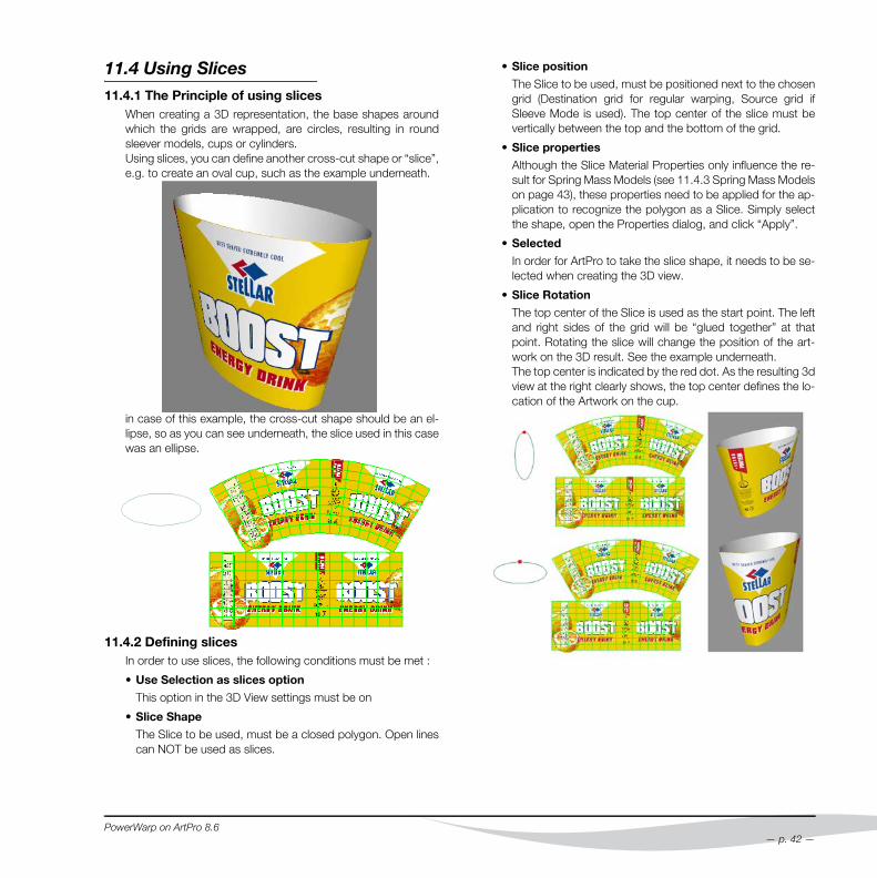
When creating a 3D representation, the base shapes aroundwhich the grids are wrapped, are circles, resulting in roundsleever models, cups or cylinders.Using slices, you can define another cross-cut shape or “slice”,e.g. to create an oval cup, such as the example underneath.
in case of this example, the cross-cut shape should be an el-lipse, so as you can see underneath, the slice used in this casewas an ellipse.
11.4.2 Defining slicesIn order to use slices, the following conditions must be met :
• Use Selection as slices option
This option in the 3D View settings must be on
• Slice Shape
The Slice to be used, must be a closed polygon. Open linescan NOT be used as slices.
PowerWarp on ArtPro 8.6
• Slice position
The Slice to be used, must be positioned next to the chosengrid (Destination grid for regular warping, Source grid ifSleeve Mode is used). The top center of the slice must bevertically between the top and the bottom of the grid.
• Slice properties
Although the Slice Material Properties only influence the re-sult for Spring Mass Models (see 11.4.3 Spring Mass Modelson page 43), these properties need to be applied for the ap-plication to recognize the polygon as a Slice. Simply selectthe shape, open the Properties dialog, and click “Apply”.
• Selected
In order for ArtPro to take the slice shape, it needs to be se-lected when creating the 3D view.
• Slice Rotation
The top center of the Slice is used as the start point. The leftand right sides of the grid will be “glued together” at thatpoint. Rotating the slice will change the position of the art-work on the 3D result. See the example underneath.The top center is indicated by the red dot. As the resulting 3dview at the right clearly shows, the top center defines the lo-cation of the Artwork on the cup.
— p. 42 —
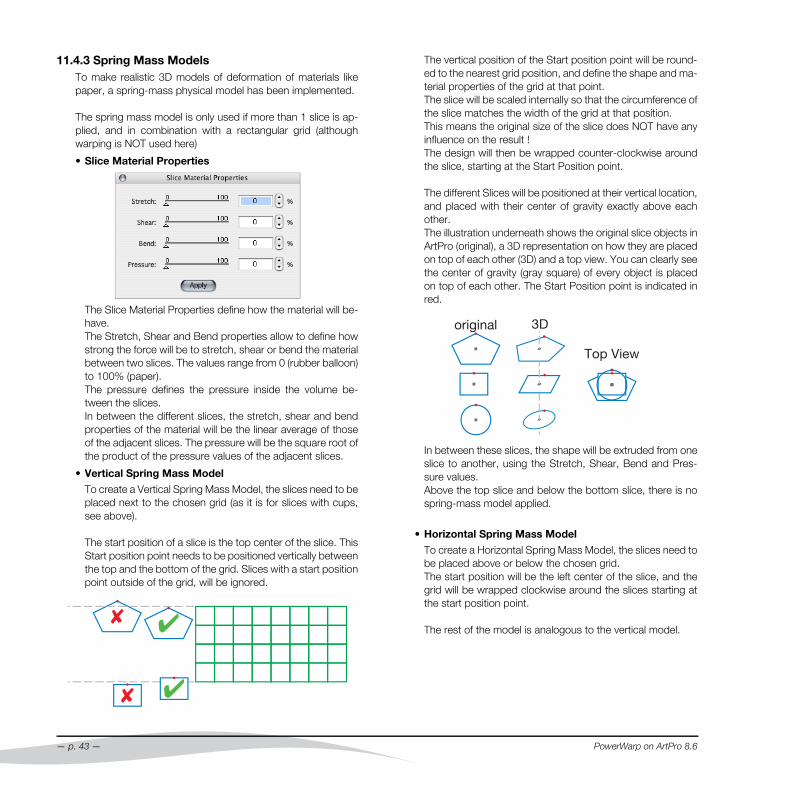
11.4.3 Spring Mass ModelsTo make realistic 3D models of deformation of materials likepaper, a spring-mass physical model has been implemented.
The spring mass model is only used if more than 1 slice is ap-plied, and in combination with a rectangular grid (althoughwarping is NOT used here)
• Slice Material Properties
The Slice Material Properties define how the material will be-have. The Stretch, Shear and Bend properties allow to define howstrong the force will be to stretch, shear or bend the materialbetween two slices. The values range from 0 (rubber balloon)to 100% (paper). The pressure defines the pressure inside the volume be-tween the slices.In between the different slices, the stretch, shear and bendproperties of the material will be the linear average of thoseof the adjacent slices. The pressure will be the square root ofthe product of the pressure values of the adjacent slices.
• Vertical Spring Mass Model
To create a Vertical Spring Mass Model, the slices need to beplaced next to the chosen grid (as it is for slices with cups,see above).
The start position of a slice is the top center of the slice. ThisStart position point needs to be positioned vertically betweenthe top and the bottom of the grid. Slices with a start positionpoint outside of the grid, will be ignored.
— p. 43 —
The vertical position of the Start position point will be round-ed to the nearest grid position, and define the shape and ma-terial properties of the grid at that point.The slice will be scaled internally so that the circumference ofthe slice matches the width of the grid at that position. This means the original size of the slice does NOT have anyinfluence on the result !The design will then be wrapped counter-clockwise aroundthe slice, starting at the Start Position point.
The different Slices will be positioned at their vertical location,and placed with their center of gravity exactly above eachother.The illustration underneath shows the original slice objects inArtPro (original), a 3D representation on how they are placedon top of each other (3D) and a top view. You can clearly seethe center of gravity (gray square) of every object is placedon top of each other. The Start Position point is indicated inred.
In between these slices, the shape will be extruded from oneslice to another, using the Stretch, Shear, Bend and Pres-sure values.Above the top slice and below the bottom slice, there is nospring-mass model applied.
• Horizontal Spring Mass Model
To create a Horizontal Spring Mass Model, the slices need tobe placed above or below the chosen grid.The start position will be the left center of the slice, and thegrid will be wrapped clockwise around the slices starting atthe start position point.
The rest of the model is analogous to the vertical model.
PowerWarp on ArtPro 8.6
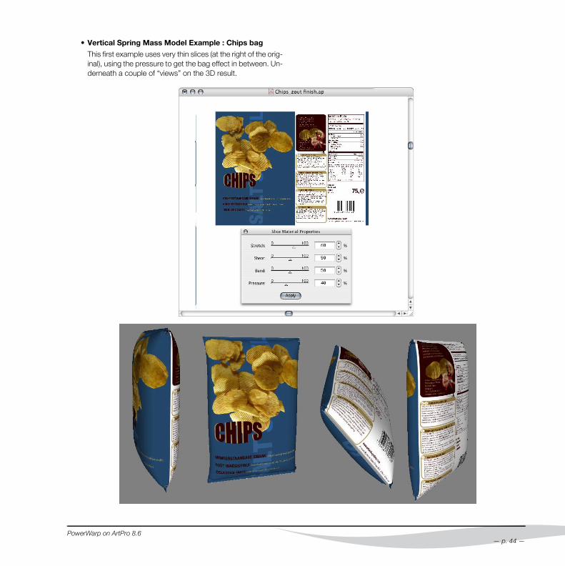
• Vertical Spring Mass Model Example : Chips bag
This first example uses very thin slices (at the right of the orig-inal), using the pressure to get the bag effect in between. Un-derneath a couple of “views” on the 3D result.
PowerWarp on ArtPro 8.6
— p. 44 —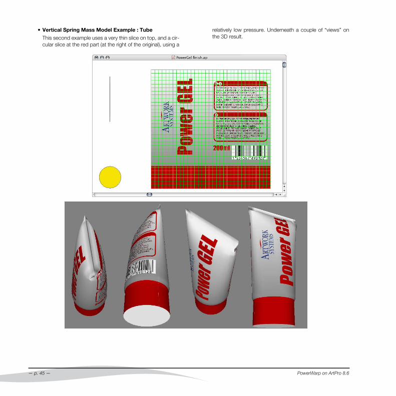
• Vertical Spring Mass Model Example : Tube
This second example uses a very thin slice on top, and a cir-cular slice at the red part (at the right of the original), using a
— p. 45 —
relatively low pressure. Underneath a couple of “views” onthe 3D result.
PowerWarp on ArtPro 8.6
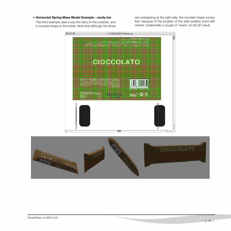
• Horizontal Spring Mass Model Example : candy bar
This third example uses a very thin slice on the outsides, anda rounded shape to the inside. Note that although the slices
PowerWarp on ArtPro 8.6
are overlapping at the right side, the rounded shape comesfirst, because of the location of the start position point (leftcenter). Underneath a couple of “views” on the 3D result.
— p. 46 —
12. Appendix
12.1 Grid File FormatsThe coordinates should be defined in an ASCI file.The coordinates can be separated by a blank space, a tabula-tion or a carriage return.The grid files are normally created with a spreadsheet, but theycan be typed in a plain text document too. There are 3 ways todefine a grid: based on a normal grid (= normal or transposegrid) or based on a parallel grid.The normal grid allows for more possibilities since it can haveany shape. For parallel grids, the grid must contain parallel linesonly.
A grid file should contain :
• ArtPro Warp File V1.0
• Unit:
millimeters or inches can be used (MM or INCH)
• Width
indicates the number of horizontal grid points
• Height
indicates the number of vertical grid points
• Quadrants
indicates the number of quad-rants the full grid consists of.In this way, it is possible to de-scribe for a regular grid only apart (a half or a quarter) of thegrid needed: it will be mirroredhorizontally to the right (2Quadrants) and verticallydown (4 Quadrants). See also• Full - 1/2 - 1/4 - x2 - x4 on page 6 and • Full - 1/2 - 1/4 onpage 8
• Source Grid
starts with begin and ends with end. In between these twowords, you find the source grid coordinates.
• Destination Grid
:starts with begin and ends with end. In between these twowords, you find the destination grid coordinates.You can easily check this by creating a small grid file yourselfand opening it in Simpletext.
2nd
quadrant1st
quadrant
3rd
quadrant4th
quadrant
— p. 47 —
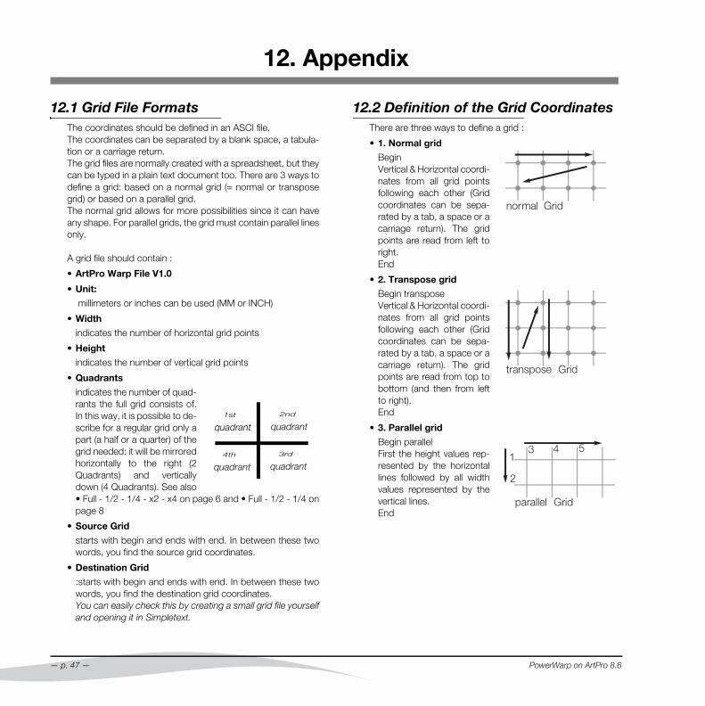
12.2 Definition of the Grid CoordinatesThere are three ways to define a grid :
• 1. Normal grid
BeginVertical & Horizontal coordi-nates from all grid pointsfollowing each other (Gridcoordinates can be sepa-rated by a tab, a space or acarriage return). The gridpoints are read from left toright.End
• 2. Transpose grid
Begin transposeVertical & Horizontal coordi-nates from all grid pointsfollowing each other (Gridcoordinates can be sepa-rated by a tab, a space or acarriage return). The gridpoints are read from top tobottom (and then from leftto right).End
• 3. Parallel grid
Begin parallelFirst the height values rep-resented by the horizontallines followed by all widthvalues represented by thevertical lines.End
PowerWarp on ArtPro 8.6

PowerWarp on ArtPro 8.6
NORMAL
ArtPro Warp file V1.0
Unit: MMWidth : 8Height: 5Quadrants: 2
begin0 0 0 10 0 20 0 30 0 40 0 5010 0 10 10 10 20 10 30 10 40 10 5020 0 20 10 20 20 20 30 20 40 20 5030 0 30 10 30 20 30 30 30 40 30 5040 0 40 10 40 20 40 30 40 40 40 50end
begin0 0 1 10 3 20 4 30 6 40 8 5010 0 11 10 12 20 13 30 13 40 14 5020 0 20 10 20 20 20 30 20 40 20 5030 0 29 10 28 20 27 30 27 40 26 5040 0 39 10 37 20 36 30 34 40 32 50end
TRANSPOSE
begin transpose0.09.8703840.011.882970.014.171880.03.55052710.026273.65603112.025713.73695214.287647.28023110.37447.52238812.36797.68026414.61256end
PARALLEL
ArtPro Warp file V1.0
Unit: MMWidth : 25Height: 18Quadrants: 4
begin parallel0.03.06.09.00.03.06.09.0end
12.3 Grid Examples• A grid consisting out of 2 quadrants:
— p. 48 —
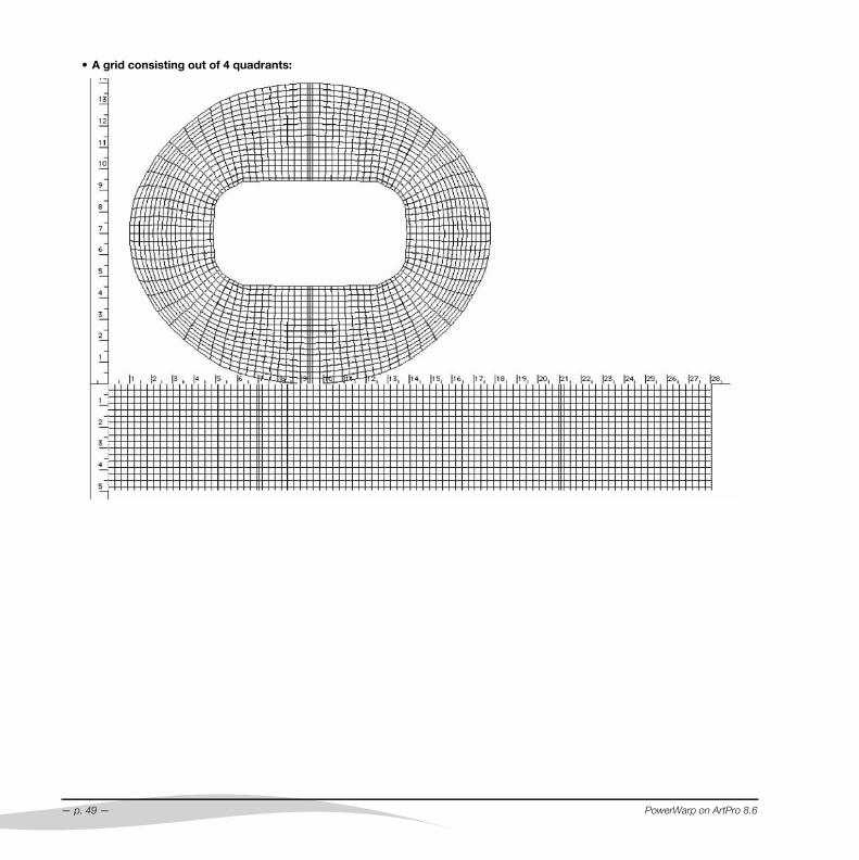
• A grid consisting out of 4 quadrants:
— p. 49 —
PowerWarp on ArtPro 8.6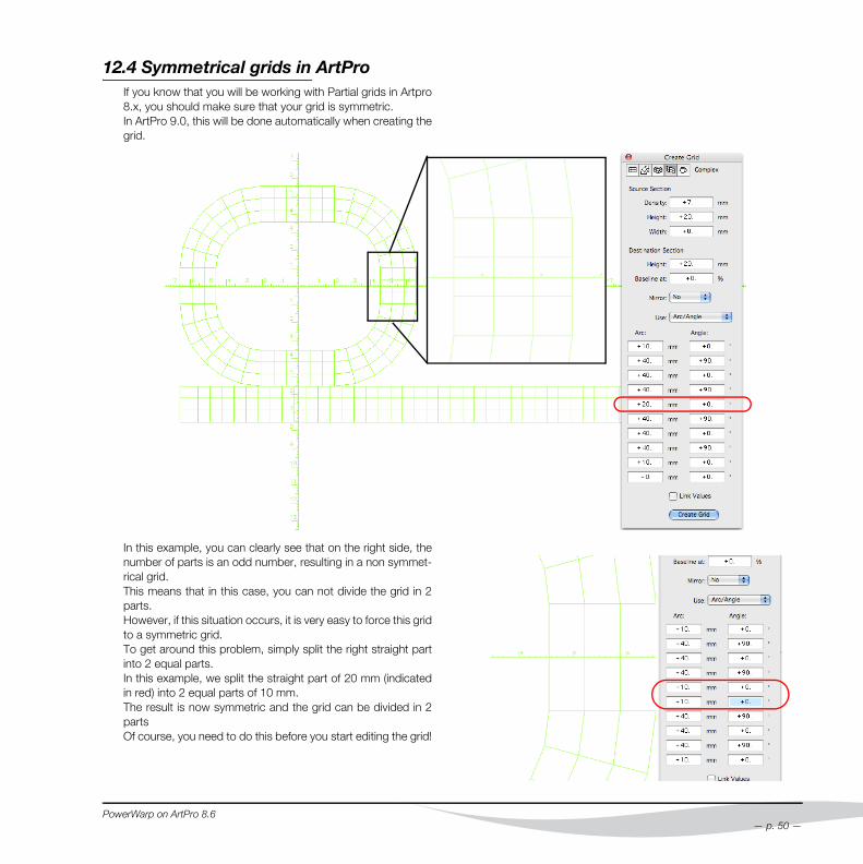
12.4 Symmetrical grids in ArtProIf you know that you will be working with Partial grids in Artpro8.x, you should make sure that your grid is symmetric.In ArtPro 9.0, this will be done automatically when creating thegrid.
PowerWarp on ArtPro 8.6
In this example, you can clearly see that on the right side, the
number of parts is an odd number, resulting in a non symmet-rical grid.This means that in this case, you can not divide the grid in 2parts.However, if this situation occurs, it is very easy to force this gridto a symmetric grid. To get around this problem, simply split the right straight partinto 2 equal parts.In this example, we split the straight part of 20 mm (indicatedin red) into 2 equal parts of 10 mm.The result is now symmetric and the grid can be divided in 2partsOf course, you need to do this before you start editing the grid!— p. 50 —

12.5 Formulas of Link Values
The following are formulas which explain the relation betweenthe parameters from the Create Grid dialog boxes.
Source width = R x 2 x angle / 180 x pi (with angle in degrees)
R = Inner Radius + Baseline at / 100 x Destination Height
Having a relation between parameters means that certain com-binations of values are not possible. Therefor, when filling insome values, with the option Link Values on, other values maychange automatically using the above formula. We describe indetail what parameters are adjusted automatically.
• Angle
Will update the Source Width. Will also force Source andDestination Height to the same value if the Baseline at pa-rameter is not zero.
• Source Height
Will update the Source Width. No changes will appear if theBaseline at is zero. Destination Height will also be set to thisvalue.
• Destination Height
If this value is different from the Source Height, the Baselineat parameter will be forced to zero. Source Width will be setto Radius x angle.
• Source Width
Will update the Radius if this version is still zero. If the Radiusalready has a value, then the Baseline at percentage is up-dated.
• Radius / Arc length
Will update the Source Width value.
• Baseline At
Will update the Source Width value. Will also force Sourceand Destination Height to have the same value, if Baseline atis set to zero
— p. 51 —
PowerWarp on ArtPro 8.6
Index
Numerics
3D View 39export 41spring mass models 43using slices 40, 42
A
Angle 13Arc 13
B
Baseline 22Blister packs 14
C
Cans 17Cardboard Box
rounded cardboard box 27Ceramic
flat ceramic printing 22using the baseline 22
Colorcompensate 11
Compensate 10compensate graphics for sleeves 32path compensation for sleeves 35
Compensate Color 11Cone Cups 30Conversion 5Convert
grid to paths 8Create
grid creation 12Create Grid 8
PowerWarp on ArtPro 8.6
Cupscone cups 30drinking cups 25
D
Deleteerase grid 8
Density 13Direction
same direction 9same direction, same waypoint 10
Distortion 11Drawn caps 17Drinking Cups 25
E
Editgrid editing 8
Erase Grid 8Export
3D view 41Extend Source Grid 7
F
Fitfit to path 10
Flat Ceramic Printing 22Flat color 5Flip Source Grid 7
G
Gradientsnoise for gradients 7resolution for gradients 7warping gradients 5
Gridbasic grid warping 12create 8creation for blister packs 14creation for cone cups 30creation for oval cans 20creation for round metal cups and
drawn caps 17creation for sardine cans 21creation of a grid for sleeves 35erase 8example for blister packs 16extend source grid 7File Formats 47flip source grid 7Full-1/2-1/4 6, 8grid creation 12grid editing 8grid to paths 8Load 6manual grid creation 12printing a grid 13save grid 8show grid 8sleeve grid 12undo 11units for save 8
Grid File Formats 47Gridwarp
Definition 4Gridwarp Module 4
H
Height 13
— p. 52 —
I
Imagesoversampling 7Resolution for CT 7resolution for gradients 7warping images 5
K
Keep Original 6
L
Lineartconvert grid to lineart 8
LoadFull-1/2-1/4 6
Load grid 6Locality 9, 10
M
Metal Cups 17
N
Noise for Gradients 7
O
Oversampling 7
P
Pathfit to path 10
Printprinting a grid 13
Procedure 5
— p. 53 —
Q
Quadrants 6, 8, 47
R
Radius 13Resolution
for CT 7for gradients 7
Reverse Warp 6Rounded Cardboard Box 27
S
SaveFull-1/2-1/4 8save 3D view as movie 41save 3D view frame as tiff 41save grid 8save grid in inch 8
Show Grid 8Shrink foil/
see SleeveSleeve 32
design for sleeves 32sleeve grid 12sleeve mode 7, 36warping text 37when? 32
Slices 40, 42Spring Mass Models 43System requirements 4
T
Textsleeves 37warping text 5
U
Undo Grid 11
V
View3D view 39
Visualisationshow grid 8
W
Warp 6keep original 6reverse 6
Warpingconversion 5
Waypointsame direction, same waypoint 10same waypoint 9
Width 13
PowerWarp on ArtPro 8.6

Artwork Systems Group N.V.EskoArtwork
Kortrijksesteenweg 10959051 GentBelgium
Tel. +32 9 216 92 11Fax +32 9 216 94 64
AWSG LimitedMary Rosse Centre (Phase II)
Holland RoadThe National Technology Road
Limerick, IrelandTel. +353 61 33 61 36Fax +353 61 33 68 33
Artwork Systems S.A.Paris Nord II
47 Allée des ImpressionnistesBP 52335 Villepinte
F-95941 Roissy CDG Cedex, FranceTel. +33 (0)1 48 17 00 90Fax +33 (0)1 49 38 09 78
Artwork Systems Inc.219A Rittenhouse Circle
Bristol, PA 19007USA
Tel. +1 215 826 4500Fax. +1 215 826 4510
Artwork Systems Ltd.The Business Centre
Edward Street - RedditchWorcestershire B97 6HA
United KingdomTel. +44 (0) 1527-592550Tel. +44 (0) 1527-592466
Artwork Systems GmbH & Co. KGBurkheimer Straße 3
D-79111 FreiburgGermany
Tel. +49 761 452 98 0Fax +49 761 452 98 22
ArtPro 8.6Copyright © 1992 - 2008, Artwork Systems N.V.
All Rights Reserved
Related Documents