Quick Setup 1 Plan Plan the installation including all alarm detection devices, zone expanders, keypads and other required modules. 2 Mount Decide on a location for the alarm panel and secure it to the wall using suitable mounting hardware. 3 Wire Complete all wiring including modules, zones, bells/sirens, telephone line connections and ground connections. Record module serial numbers on page 16. 4 Power Connect the battery and power up the system. The battery must be connected. 5 Enroll First Keypad Hardwired: Wire the keypad to the Corbus, power up the alarm panel then press any button on the keypad. Wireless: Wire the HSM2Host to the Corbus, then power up the alarm panel and a wireless keypad. Press any button on the keypad to enroll it. The HSM2Host is then enrolled on the alarm panel. Alternately, enroll an RF keypad. 6 Enroll modules [*][8][Installer Code][902] subsection [000]. Press [*] to begin auto-enrollment. Module slots are automatically assigned. Use scroll keys to view slots. Change slot by typing a 2-digit number. 7 Enroll wireless devices [*][8][Installer Code][804] subsection [000]. Note: An HSM2HOST or RF keypad must be enrolled first. 8 Program Basic programming: [*][8][installer code] [001]/[002]> Zone Type/Zone Attribute [005]>[001] Partition 1 Timers: – Entry Delay 1 – Entry Delay 2 – Exit Delay [301]>[001] Phone #1 [310]>[000] System Account Code. 9 Test Test the panel completely to ensure that all features and functions operate as programmed. – [901] Walk Test – [904] [000] Wireless Placement Test. Compatible Devices Throughout this document, x in the model number represents the operating frequency of the device as follows: 9 (912-919 MHz), 8 (868MHz), 4 (433MHz). Note: Only models operating in the band 912-919 MHz are UL/ULC listed where indicated. Only UL approved devices are to be used with UL/ULC listed systems. Table 1-1 Compatible Devices Modules Wireless keypads: HS2LCDWFx HS2LCDWFPx HS2LCDWFPVx Hardwired keypads with 2-way wireless integration module: HS2LCDRFx HS2LCDRFPx HS2ICNRFx HS2ICNRFPx Hardwired keypads: HS2LCD HS2LCDP HS2ICN HS2ICNP HS2LED Touchscreen Keypad HS2TCHP 2-way wireless integration module: HSM2HOSTx 8-zone expander: HSM2108 8-output expander: HSM2208 Power supply: HSM2300 4 high current output expander: HSM2204 Alternate communicator: 3G2080E 3G2080RE TL280E TL280RE LE2080(R) TL280LE(R) TL2803GE TL2803GRE TL8803G TL880LT TL880LE PCL-422 Hardwired Devices 2-wire smoke detectors: FSA-210x FSA-210xT FSA-210xS FSA-210xST FSA-210xLST FSA-210xR FSA-210xRT FSA-210xRS FSA-210xRST FSA-210xLRST y= A, B, or C A: ULC listed models B: UL listed models C: European and Australian models 4-wire smoke detectors: FSA-410x FSA-410xT FSA-410xS FSA-410xST FSA-410xLST FSA-410xR FSA-410xRT FSA-410xRS FSA-410xRST FSA-410xLRST y= A, B, or C A: ULC listed models B: UL listed models C: European and Australian models CO detectors: CO-12/24 12-24SIR FW-CO12 FW-CO1224 CO1224 Wireless Devices PG smoke detectors PGx926 PG smoke and heat detector PGx936, PGx916 PG CO detector PGx933, PGx913 PG PIR motion detectors PGx904(P) PG PIR + camera motion detector PGx934(P) PG curtain motion detector PGx924 PG dual tech motion detector PGx984(P) PG mirror motion detector PGx974(P) PG outdoor motion detector PGx994 PG glass break detector PGx912, PGx922 PG shock detector PGx935 PG flood detector PGx985 PG temperature detector (indoor use) PGx905 Outdoor temperature probe (requires PGx905) PGTEMP-PROBE PG flat PIR PGx914 PG recessed Contact PGx307 PG ceiling mount detector with Smart Presence – Short Range PGx862 PG ceiling mount detector with Smart Presence – Long Range PGx872 PG outdoor contact PGx312 PG outdoor curtain PIR PGx902 PG keys PGx939 PGx929 PG panic key PGx938 PG 2-button key PGx949 PG sirens: PGx901 PGx911 PG repeater: PGx920 PG door/window contacts: PGx303, PGx975 PG door/window contact w/ AUX PGx945 Central Station Receivers SG-System I, II, III, IV, 5 Enclosures PC5003C, PC4050CR, PC4050CAR, CMC-1, PC4051C. Other enclosures are available to suit a variety of system configurations. WARNING: This manual contains information on limitations regarding product use and function and information on the limitations as to liability of the manufacturer. The entire manual should be carefully read. To download the full installation manual and register your product, please visit: www.DSC.com/m/29009812 or scan the QR code to the right. PowerSeries Neo Alarm Control Installation Guide Use this guide in conjunction with the PowerSeries Neo Reference Manual available online from the DSC website.

Welcome message from author
This document is posted to help you gain knowledge. Please leave a comment to let me know what you think about it! Share it to your friends and learn new things together.
Transcript
Quick Setup1 Plan Plan the installation including all alarm detection devices,
zone expanders, keypads and other required modules.2 Mount Decide on a location for the alarm panel and secure it to the
wall using suitable mounting hardware.3 Wire Complete all wiring including modules, zones, bells/sirens,
telephone line connections and ground connections. Recordmodule serial numbers on page 16.
4 Power Connect the battery and power up the system. The batterymust be connected.
5 EnrollFirstKeypad
Hardwired: Wire the keypad to the Corbus, power up thealarm panel then press any button on the keypad. Wireless:Wire the HSM2Host to the Corbus, then power up the alarmpanel and a wireless keypad. Press any button on the keypad toenroll it. The HSM2Host is then enrolled on the alarm panel.Alternately, enroll an RF keypad.
6 Enrollmodules
[*][8][Installer Code][902] subsection [000]. Press [*] tobegin auto-enrollment. Module slots are automaticallyassigned. Use scroll keys to view slots. Change slot by typing a2-digit number.
7 Enrollwirelessdevices
[*][8][Installer Code][804] subsection [000]. Note: AnHSM2HOST or RF keypad must be enrolled first.
8 Program Basic programming: [*][8][installer code] [001]/[002]> ZoneType/Zone Attribute [005]>[001] Partition 1 Timers: – EntryDelay 1 – Entry Delay 2 – Exit Delay [301]>[001] Phone #1[310]>[000] System Account Code.
9 Test Test the panel completely to ensure that all features andfunctions operate as programmed. – [901] Walk Test – [904][000] Wireless Placement Test.
Compatible DevicesThroughout this document, x in the model number represents the operatingfrequency of the device as follows: 9 (912-919 MHz), 8 (868MHz), 4(433MHz).Note: Only models operating in the band 912-919 MHz are UL/ULC listedwhere indicated. Only UL approved devices are to be used with UL/ULClisted systems.Table 1-1 Compatible DevicesModulesWireless keypads: HS2LCDWFx
HS2LCDWFPxHS2LCDWFPVx
Hardwired keypads with 2-way wirelessintegration module:
HS2LCDRFxHS2LCDRFPx
HS2ICNRFxHS2ICNRFPx
Hardwired keypads: HS2LCDHS2LCDPHS2ICN
HS2ICNPHS2LED
Touchscreen Keypad HS2TCHP2-way wireless integration module: HSM2HOSTx8-zone expander: HSM21088-output expander: HSM2208Power supply: HSM23004 high current output expander: HSM2204
Alternate communicator: 3G2080E3G2080RETL280ETL280RELE2080(R)TL280LE(R)
TL2803GETL2803GRETL8803GTL880LTTL880LEPCL-422
Hardwired Devices2-wire smoke detectors: FSA-210x
FSA-210xTFSA-210xSFSA-210xSTFSA-210xLST
FSA-210xRFSA-210xRTFSA-210xRSFSA-210xRSTFSA-210xLRST
y= A, B, or CA: ULC listed modelsB: UL listed modelsC: European and Australian models4-wire smoke detectors: FSA-410x
FSA-410xTFSA-410xSFSA-410xSTFSA-410xLST
FSA-410xRFSA-410xRTFSA-410xRSFSA-410xRSTFSA-410xLRST
y= A, B, or CA: ULC listed modelsB: UL listed modelsC: European and Australian modelsCO detectors: CO-12/24
12-24SIRFW-CO12
FW-CO1224CO1224
Wireless DevicesPG smoke detectors PGx926PG smoke and heat detector PGx936, PGx916PG CO detector PGx933, PGx913PG PIR motion detectors PGx904(P)PG PIR + camera motion detector PGx934(P)PG curtain motion detector PGx924PG dual tech motion detector PGx984(P)PG mirror motion detector PGx974(P)PG outdoor motion detector PGx994PG glass break detector PGx912, PGx922PG shock detector PGx935PG flood detector PGx985PG temperature detector (indoor use) PGx905Outdoor temperature probe (requires PGx905) PGTEMP-PROBEPG flat PIR PGx914PG recessed Contact PGx307PG ceiling mount detector with Smart Presence – Short Range PGx862PG ceiling mount detector with Smart Presence – Long Range PGx872PG outdoor contact PGx312PG outdoor curtain PIR PGx902PG keys PGx939
PGx929PG panic key PGx938PG 2-button key PGx949PG sirens: PGx901
PGx911PG repeater: PGx920PG door/window contacts: PGx303, PGx975PG door/window contact w/ AUX PGx945
Central Station ReceiversSG-System I, II, III, IV, 5
EnclosuresPC5003C, PC4050CR, PC4050CAR, CMC-1, PC4051C. Other enclosures are available to suit a varietyof system configurations.
WARNING: This manual contains information on limitations regarding product use and function and information on thelimitations as to liability of the manufacturer. The entire manual should be carefully read.
To download the full installation manual and register your product, please visit:www.DSC.com/m/29009812 or scan the QR code to the right.
PowerSeries Neo Alarm Control Installation GuideUse this guide in conjunction with the PowerSeries Neo Reference Manual available online from the DSC website.
PowerSeries Neo Installation Guide
Safety Instructions for Service PersonnelWhen using equipment connected to the telephone network, always follow thebasic safety instructions provided with this product. Inform the end-user of thesafety precautions that must be observed when operating this equipment.Before Installing The EquipmentEnsure your package includes the following items:l HS2016-4/HS2016/2032/2064/2128 alarm controllerl Power Supply, direct plug-inl Installation and user guides, including the safety instructionsSelecting A Suitable Location For The Alarm ControllerRefer to the following list to find a suitable location to install this equipment:l Locate near a telephone socket and power outlet.l Select a location free from vibration and shock.l Place alarm controller on a flat, stable surface and follow the installation
instructions.l Do not locate the equipment where people may walk on the secondary circuit
cable(s).l Do not connect alarm controller to the same electrical circuit as large appli-
ances.l Do not select a location that exposes your alarm controller to direct sunlight,
excessive heat, moisture, vapors, chemicals or dust.l Do not install this equipment near water. (e.g., bath tub, kitchen/laundry
sink, wet basement, near a swimming pool).l Do not install this equipment and accessories in areas where risk of explo-
sion exists.l Do not connect this equipment to electrical outlets controlled by wall
switches or automatic timers.l Avoid interference sources.l Avoid installing equipment near heaters, air conditioners, ventilators, and
refrigerators.l Avoid locating equipment close to or on top of large metal objects (e.g., wall
studs).See "Locating Detectors and Escape Plan" on page 17 for information on locatingsmoke and CO detectors.Safety Precautions Required During Installationl Never install this equipment and/or telephone wiring during a lightning
storm.l Never touch uninsulated telephone wires or terminals unless the telephone
line has been disconnected at the network interface.l Position cables so that accidents can not occur. Connected cables must not be
subject to excessive mechanical strain.l Use only the power supply provided with this equipment. Use of unau-
thorized power supplies may cause damage.l For direct plug-in versions, use the power supply provided with the device.WARNING: This equipment has no mains on/off switch. The plug of the directplug-in power supply is intended to serve as the disconnecting device if theequipment must be quickly disconnected. It is imperative that access to the mainsplug and associated mains socket/outlet is never obstructed.IMPORTANT NOTESl This equipment is stationary-fixed with a direct plug-in external transformer
or a permanently connected internal transformer dependent on the region. Itmust be installed by Service Persons only (Service Person is defined as a per-son having the appropriate technical training and experience necessary to beaware of hazards to which that person may be exposed in performing a taskand of measures to minimize the risks to that person or other persons). Itmust be installed and used within an environment that provides the pollutiondegree max 2, over voltages category II, in non-hazardous, indoor locationsonly.
l This equipment has no mains on/off switch; if the equipment must be quicklydisconnected, the plug of the direct plug-in power supply is intended to serveas the disconnecting device. It is imperative that access to the mains plug andassociated mains socket/outlet, is never obstructed.
l For permanently connected versions, the fuse in the power connector servesas the disconnecting device. The disconnect device will only remove themains power and will not disconnect battery power. The installer is respons-ible to ensure that a readily accessible mains disconnect device is incor-porated in the building for permanently connected installations.
l There are no end user replaceable parts replaceable within this equipment.l Before servicing, disconnect the mains power, battery and telephone con-
nections.l The equipment enclosure must be secured to the building structure before
operation.l All national wiring rules must be observed.l The wiring (cables) used for installation of the alarm system and accessor-
ies, shall be insulated with PVC, TFE, PTFE, FEP, Neoprene or Polyamide.l Do not route any wiring over circuit boards
l Ensure that cables are positioned so that accidents cannot occur:- Internal wiring must be routed in a manner that prevents;- Excessive strain or loosening of wire on terminal connections;- Damage of conductor or insulation.
l Disposal of used batteries must be made in accordance with local wasterecovery and recycling regulations.
l Use authorized accessories only with this equipment.l Do not place any object on the top of the cabinet.l Do not spill any liquids on the cabinet.l Do not touch the equipment and its connected cables during an electrical
storm; there may be a risk of electric shock.l Save these safety instructions for future use.l These safety instructions should not prevent you from contacting the dis-
tributor and/or the manufacturer to obtain any further clarification and/oranswers to your concerns.
InstallationMounting the EnclosureLocate the panel in a dry area, preferably near an unswitched AC power sourceand the incoming telephone line. Complete all wiring before applying AC orconnecting the battery.
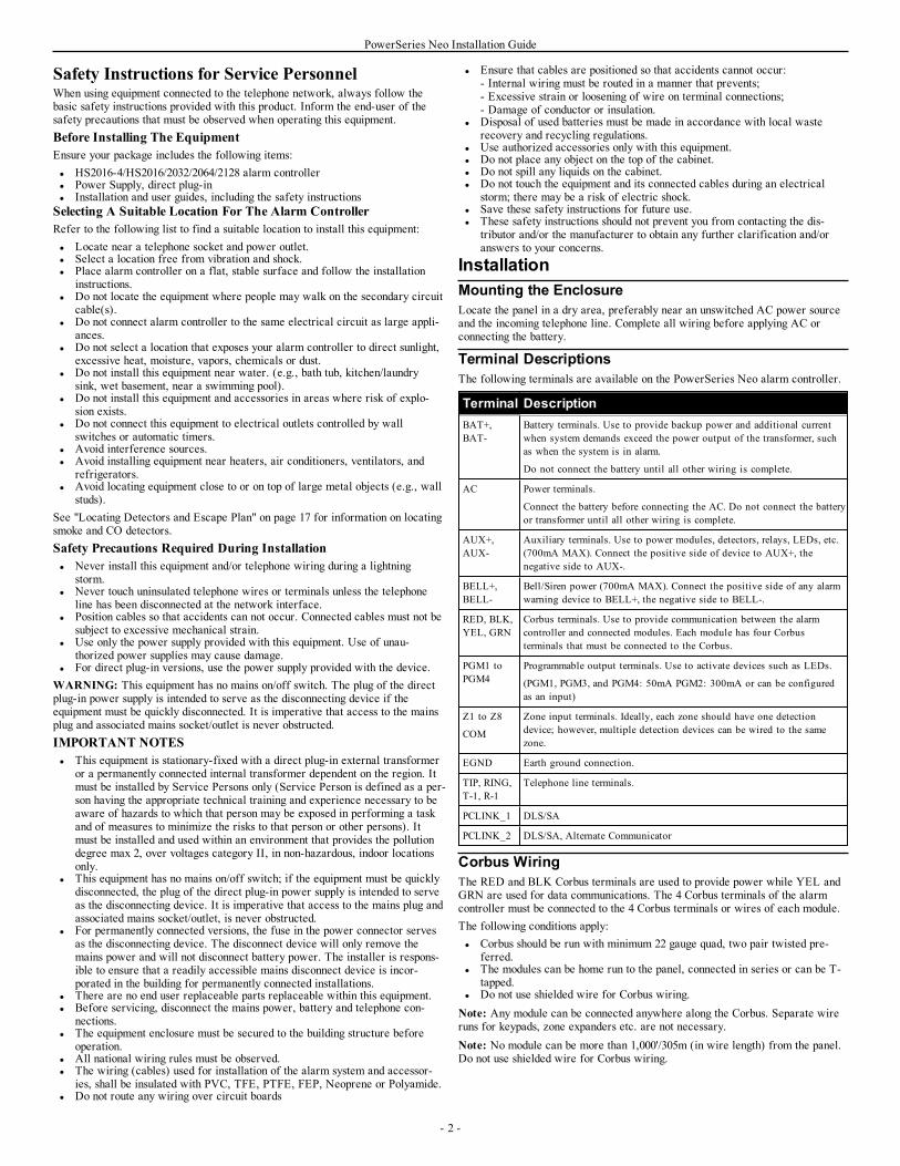
Terminal DescriptionsThe following terminals are available on the PowerSeries Neo alarm controller.
Terminal DescriptionBAT+,BAT-
Battery terminals. Use to provide backup power and additional currentwhen system demands exceed the power output of the transformer, suchas when the system is in alarm.
Do not connect the battery until all other wiring is complete.
AC Power terminals.
Connect the battery before connecting the AC. Do not connect the batteryor transformer until all other wiring is complete.
AUX+,AUX-
Auxiliary terminals. Use to power modules, detectors, relays, LEDs, etc.(700mA MAX). Connect the positive side of device to AUX+, thenegative side to AUX-.
BELL+,BELL-
Bell/Siren power (700mA MAX). Connect the positive side of any alarmwarning device to BELL+, the negative side to BELL-.
RED, BLK,YEL, GRN
Corbus terminals. Use to provide communication between the alarmcontroller and connected modules. Each module has four Corbusterminals that must be connected to the Corbus.
PGM1 toPGM4
Programmable output terminals. Use to activate devices such as LEDs.
(PGM1, PGM3, and PGM4: 50mA PGM2: 300mA or can be configuredas an input)
Z1 to Z8
COM
Zone input terminals. Ideally, each zone should have one detectiondevice; however, multiple detection devices can be wired to the samezone.
EGND Earth ground connection.
TIP, RING,T-1, R-1
Telephone line terminals.
PCLINK_1 DLS/SA
PCLINK_2 DLS/SA, Alternate Communicator
Corbus WiringThe RED and BLK Corbus terminals are used to provide power while YEL andGRN are used for data communications. The 4 Corbus terminals of the alarmcontroller must be connected to the 4 Corbus terminals or wires of each module.The following conditions apply:l Corbus should be run with minimum 22 gauge quad, two pair twisted pre-
ferred.l The modules can be home run to the panel, connected in series or can be T-
tapped.l Do not use shielded wire for Corbus wiring.Note: Any module can be connected anywhere along the Corbus. Separate wireruns for keypads, zone expanders etc. are not necessary.Note: No module can be more than 1,000'/305m (in wire length) from the panel.Do not use shielded wire for Corbus wiring.
- 2 -
PowerSeries Neo Installation Guide
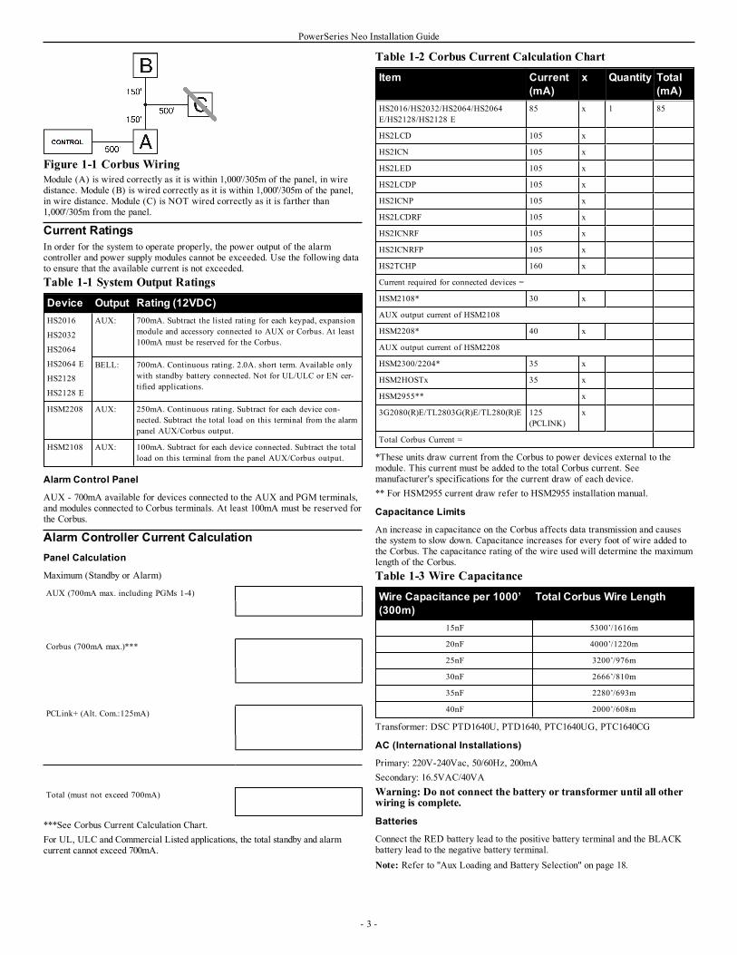
Figure 1-1 Corbus WiringModule (A) is wired correctly as it is within 1,000'/305m of the panel, in wiredistance. Module (B) is wired correctly as it is within 1,000'/305m of the panel,in wire distance. Module (C) is NOT wired correctly as it is farther than1,000'/305m from the panel.
Current RatingsIn order for the system to operate properly, the power output of the alarmcontroller and power supply modules cannot be exceeded. Use the following datato ensure that the available current is not exceeded.Table 1-1 System Output Ratings
Device Output Rating (12VDC)HS2016
HS2032
HS2064
HS2064 E
HS2128
HS2128 E
AUX: 700mA. Subtract the listed rating for each keypad, expansionmodule and accessory connected to AUX or Corbus. At least100mA must be reserved for the Corbus.
BELL: 700mA. Continuous rating. 2.0A. short term. Available onlywith standby battery connected. Not for UL/ULC or EN cer-tified applications.
HSM2208 AUX: 250mA. Continuous rating. Subtract for each device con-nected. Subtract the total load on this terminal from the alarmpanel AUX/Corbus output.
HSM2108 AUX: 100mA. Subtract for each device connected. Subtract the totalload on this terminal from the panel AUX/Corbus output.
Alarm Control Panel
AUX - 700mA available for devices connected to the AUX and PGM terminals,and modules connected to Corbus terminals. At least 100mA must be reserved forthe Corbus.
Alarm Controller Current CalculationPanel Calculation
Maximum (Standby or Alarm)
AUX (700mA max. including PGMs 1-4)
Corbus (700mA max.)***
PCLink+ (Alt. Com.:125mA)
Total (must not exceed 700mA)
***See Corbus Current Calculation Chart.For UL, ULC and Commercial Listed applications, the total standby and alarmcurrent cannot exceed 700mA.
Table 1-2 Corbus Current Calculation Chart
Item Current(mA)
x Quantity Total(mA)
HS2016/HS2032/HS2064/HS2064E/HS2128/HS2128 E
85 x 1 85
HS2LCD 105 x
HS2ICN 105 x
HS2LED 105 x
HS2LCDP 105 x
HS2ICNP 105 x
HS2LCDRF 105 x
HS2ICNRF 105 x
HS2ICNRFP 105 x
HS2TCHP 160 x
Current required for connected devices =
HSM2108* 30 x
AUX output current of HSM2108
HSM2208* 40 x
AUX output current of HSM2208
HSM2300/2204* 35 x
HSM2HOSTx 35 x
HSM2955** x
3G2080(R)E/TL2803G(R)E/TL280(R)E 125(PCLINK)
x
Total Corbus Current =
*These units draw current from the Corbus to power devices external to themodule. This current must be added to the total Corbus current. Seemanufacturer's specifications for the current draw of each device.** For HSM2955 current draw refer to HSM2955 installation manual.
Capacitance Limits
An increase in capacitance on the Corbus affects data transmission and causesthe system to slow down. Capacitance increases for every foot of wire added tothe Corbus. The capacitance rating of the wire used will determine the maximumlength of the Corbus.Table 1-3 Wire Capacitance
Wire Capacitance per 1000’(300m)
Total Corbus Wire Length
15nF 5300’/1616m
20nF 4000’/1220m
25nF 3200’/976m
30nF 2666’/810m
35nF 2280’/693m
40nF 2000’/608m
Transformer: DSC PTD1640U, PTD1640, PTC1640UG, PTC1640CG
AC (International Installations)
Primary: 220V-240Vac, 50/60Hz, 200mASecondary: 16.5VAC/40VAWarning: Do not connect the battery or transformer until all otherwiring is complete.
Batteries
Connect the RED battery lead to the positive battery terminal and the BLACKbattery lead to the negative battery terminal.Note: Refer to "Aux Loading and Battery Selection" on page 18.
- 3 -
PowerSeries Neo Installation Guide
Additional WiringZone Wiring
Power down the alarm controller and complete all zone wiring.Zones can be wired to supervise normally open devices (e.g., smoke detectors) ornormally closed devices (e.g., door contacts). The alarm panel can also beprogrammed for single end-of-line or double end-of-line resistors.Zone programming is done using the following programming sections:l [001] selects zone definitionl [013] Opt [1] for normally closed or EOL; Opt [2] for SEOL or DEOLl [201 - 208] partition assignment.Observe the following guidelines when wiring zones:l For UL listed installations use SEOL or DEOL onlyl Minimum 22 AWG wire, maximum 18 AWGl Do not use shielded wirel Do not exceed 100Ω wire resistance. Refer to the following table:Table 1-4 Burglary Zone Wiring Chart
Wire Gauge Maximum Length to EOL Resistor (ft/-meters)
22 3000 / 914
20 4900 / 1493
19 6200 / 1889
18 7800 / 2377
Figures are based on maximum wiring resistance of 100Ω.
Aux Power Wiring
These terminals provide 11.3-12.5VDC/700mA of current (shared with PGMoutputs). Connect the positive side of any device to the AUX+ terminal, thenegative side to GND. The AUX output is protected; if too much current isdrawn from these terminals (wiring short) the output is temporarily shut off untilthe problem is corrected.Note: If using a 12V, 14Ah battery, maximum AUX capacity for 24-hourstandby is 470mA.
PGM Wiring
Min/max operating voltages for devices, sensors and modules is 9.5VDC -14VDC.PGMs switch to ground when activated from the alarm controller. Connect thepositive side of the device to the AUX+ terminal and the negative side to a PGMterminal.PGM 1, 3, 4 supply up to 50mA; PGM 2 supplies up to 300mA.A relay is required for current levels greater than 50mA or 300mA. PGM2 canalso be used for 2-wire smoke detectors, 24-hr burglary input alarm.Note: Use SEOL resistors on Fire zones only.
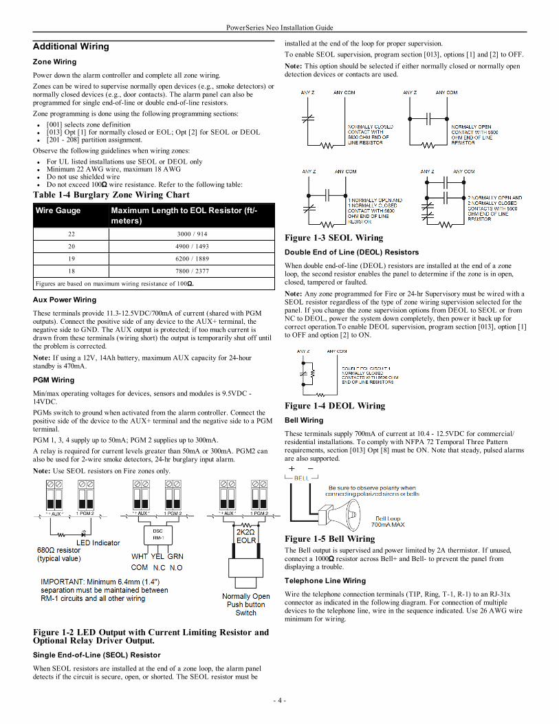
Figure 1-2 LED Output with Current Limiting Resistor andOptional Relay Driver Output.Single End-of-Line (SEOL) Resistor
When SEOL resistors are installed at the end of a zone loop, the alarm paneldetects if the circuit is secure, open, or shorted. The SEOL resistor must be
installed at the end of the loop for proper supervision.To enable SEOL supervision, program section [013], options [1] and [2] to OFF.Note: This option should be selected if either normally closed or normally opendetection devices or contacts are used.
Figure 1-3 SEOL WiringDouble End of Line (DEOL) Resistors
When double end-of-line (DEOL) resistors are installed at the end of a zoneloop, the second resistor enables the panel to determine if the zone is in open,closed, tampered or faulted.Note: Any zone programmed for Fire or 24-hr Supervisory must be wired with aSEOL resistor regardless of the type of zone wiring supervision selected for thepanel. If you change the zone supervision options from DEOL to SEOL or fromNC to DEOL, power the system down completely, then power it back up forcorrect operation.To enable DEOL supervision, program section [013], option [1]to OFF and option [2] to ON.
Figure 1-4 DEOL WiringBell Wiring
These terminals supply 700mA of current at 10.4 - 12.5VDC for commercial/residential installations. To comply with NFPA 72 Temporal Three Patternrequirements, section [013] Opt [8] must be ON. Note that steady, pulsed alarmsare also supported.
Figure 1-5 Bell WiringThe Bell output is supervised and power limited by 2A thermistor. If unused,connect a 1000Ω resistor across Bell+ and Bell- to prevent the panel fromdisplaying a trouble.
Telephone Line Wiring
Wire the telephone connection terminals (TIP, Ring, T-1, R-1) to an RJ-31xconnector as indicated in the following diagram. For connection of multipledevices to the telephone line, wire in the sequence indicated. Use 26 AWG wireminimum for wiring.
- 4 -
PowerSeries Neo Installation Guide
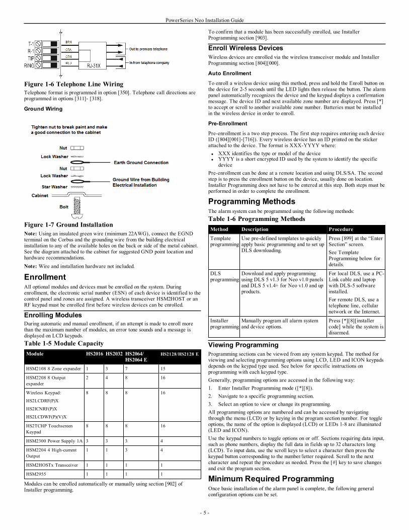
Figure 1-6 Telephone Line WiringTelephone format is programmed in option [350]. Telephone call directions areprogrammed in options [311]- [318].
Ground Wiring
Figure 1-7 Ground InstallationNote: Using an insulated green wire (minimum 22AWG), connect the EGNDterminal on the Corbus and the grounding wire from the building electricalinstallation to any of the available holes on the back or side of the metal cabinet.See the diagram attached to the cabinet for suggested GND point location andhardware recommendations.Note: Wire and installation hardware not included.
EnrollmentAll optional modules and devices must be enrolled on the system. Duringenrollment, the electronic serial number (ESN) of each device is identified to thecontrol panel and zones are assigned. A wireless transceiver HSM2HOST or anRF keypad must be enrolled first before wireless devices can be enrolled.
Enrolling ModulesDuring automatic and manual enrollment, if an attempt is made to enroll morethan the maximum number of modules, an error tone sounds and a message isdisplayed on LCD keypads.Table 1-5 Module CapacityModule HS2016 HS2032 HS2064/
HS2064 EHS2128/HS2128 E
HSM2108 8 Zone expander 1 3 7 15
HSM2208 8 Outputexpander
2 4 8 16
Wireless Keypad:
HS2LCDRF(P)X
HS2ICNRF(P)X
HS2LCDWF(P)(V)X
8 8 8 16
HS2TCHP TouchscreenKeypad
8 8 8 16
HSM2300 Power Supply 1A 3 3 3 4
HSM2204 4 High-currentOutput
1 1 3 4
HSM2HOSTx Transceiver 1 1 1 1
HSM2955 1 1 1 1
Modules can be enrolled automatically or manually using section [902] ofInstaller programming.
To confirm that a module has been successfully enrolled, use InstallerProgramming section [903].
Enroll Wireless DevicesWireless devices are enrolled via the wireless transceiver module and InstallerProgramming section [804][000].
Auto Enrollment
To enroll a wireless device using this method, press and hold the Enroll button onthe device for 2-5 seconds until the LED lights then release the button. The alarmpanel automatically recognizes the device and the keypad displays a confirmationmessage. The device ID and next available zone number are displayed. Press [*]to accept or scroll to another available zone number. Batteries must be installedin the wireless device in order to enroll.
Pre-Enrollment
Pre-enrollment is a two step process. The first step requires entering each deviceID ([804][001]-[716]). Every wireless device has an ID printed on the stickerattached to the device. The format is XXX-YYYY where:l XXX identifies the type or model of the devicel YYYY is a short encrypted ID used by the system to identify the specific
devicePre-enrollment can be done at a remote location and using DLS/SA. The secondstep is to press the enrollment button on the device, usually done on location.Installer Programming does not have to be entered at this step. Both steps must beperformed in order to complete the enrollment.
Programming MethodsThe alarm system can be programmed using the following methods:Table 1-6 Programming MethodsMethod Description Procedure
Templateprogramming
Use pre-defined templates to quicklyapply basic programming and to set upDLS downloading.
Press [899] at the “EnterSection” screen.See TemplateProgramming below fordetails.
DLSprogramming
Download and apply programmingusing DLS 5 v1.3 for Neo v1.0 panelsand DLS 5 v1.4+ for Neo v1.0 and upproducts.
For local DLS, use a PC-Link cable and laptopwith DLS-5 softwareinstalled.For remote DLS, use atelephone line, cellularnetwork or the Internet.
Installerprogramming
Manually program all alarm systemand device options.
Press [*][8][installercode] while the system isdisarmed.
Viewing ProgrammingProgramming sections can be viewed from any system keypad. The method forviewing and selecting programming options using LCD, LED and ICON keypadsdepends on the keypad type used. See below for specific instructions onprogramming with each keypad type.Generally, programming options are accessed in the following way:1. Enter Installer Programming mode ([*][8]).2. Navigate to a specific programming section.3. Select an option to view or change its programming.All programming options are numbered and can be accessed by navigatingthrough the menu (LCD) or by keying in the program section number. For toggleoptions, the name of the option is displayed (LCD) or LEDs 1-8 are illuminated(LED and ICON).Use the keypad numbers to toggle options on or off. Sections requiring data input,such as phone numbers, display the full data in fields up to 32 characters long(LCD). To input data, use the scroll keys to select a character then press thekeypad button corresponding to the number/letter required. Scroll to the nextcharacter and repeat the procedure as needed. Press the [#] key to save changesand exit the program section.
Minimum Required ProgrammingOnce basic installation of the alarm panel is complete, the following generalconfiguration options can be set.
- 5 -
PowerSeries Neo Installation Guide
[000] Language Selection(LCD keypads only)Use this section to set the language displayed by LCD keypads. To select alanguage:1. Enter Installer Programming: [*][8][Installer Code].2. Enter programming section [000]>[000].3. Key in the 2-digit number corresponding to the language required. See
below:
01 = English 11 = Swedish 22 = Bulgarian
02 = Spanish 12 = Norwegian 23 = Latvian
03 = Portuguese 13 = Danish 24 = Lithuanian
04 = French 14 = Hebrew 25 = Ukrainian
05 = Italian 15 = Greek 26 = Slovakian
06 = Dutch 16 = Turkish 27 = Serbian
07 = Polish 18 = Croatian 28 = Estonian
08 = Czech 19 = Hungarian 29 = Slovenian
09 = Finnish 20 = Romanian
10 = German 21 = Russian
Time and DateUse this section to program the alarm system clock.Menu: [*][6][Master Code] > Time and DateKeypad: [*][6][Master Code] + 01Enter time and date using the following format: (HH:MM); (MM-DD-YY).Valid time entries are 00-23 hours, 00-59 minutes. Valid date entries are 01-12months, 01-31 days.
Setting Up a PartitionPartitions are added or removed from the system by applying or removing apartition mask via Installer Programming section [200]. The number of availablepartitions depends on the alarm panel model.
Bell/Siren OperationEach partition must have a siren. The system siren connected to the bell output ofthe alarm controller can be mounted in a central location within hearing range ofall partitions. Each partition can also have wireless sirens activated only on theassigned partition.
Keypad Partition SetupKeypads can be configured to control an individual partition or all partitions. Ingeneral, a partition keypad controls the partition it is assigned to. A Globalkeypad controls all partitions. Global keypads should be placed in common areasof the premises, such as points of entry or reception areas, where the ability toarm and disarm more than one partition at a time is required.Partition keypads can also be temporarily loaned to other partitions.To select a keypad operating mode:1. Enter Installer Programming: [*][8][installer code].2. Select [861]-[876] to program keypads 1-16.l Press [000] for partition assignment.l For Global operation, key in 00.l To assign a keypad to a partition, key in 01-08 for partition 1-8.3. Press the [#] and reapeat step 2 for next keypad. When finished
programming all keypads, press the [#] key twice to exit programming.Users are assigned partition access rights via the [*][5] menu.
Assign sirens to partitions:
[804]>[000]>[551]-[556]>[000]
Set up partition account codes:
[310]>[001]-[008]
Set up partition timers:
l Entry/exit delay, settle delay – [005]>[001]-[008]l Automatic arming/disarming schedule – [151]-[158]>[001]/[002]l Auto disarming holiday schedule – [151]-[158]>[003]
l No activity arming – [151]-[158]>[006]l Automatic clock adjust – [005]>[000], option 6l Delay between dialing attempts – [377]>[012]
AssignZone Types
A zone type defines how a zone operates within the system and how it respondswhen triggered.000 - Null Zone 040 - 24-Hour Gas001 - Delay 1 041 - 24-Hour CO002 - Delay 2 042 - 24-Hour Holdup*003 - Instant 043 - 24-Hour Panic004 - Interior 045 - 24-Hour Heat005 - Interior Stay/Away 046 - 24-Hour Medical*006 - Delay Stay/Away 047 - 24-Hour Emergency007 - Delayed 24-Hour Fire 048 - 24-Hour Sprinkler*008 - Standard 24-Hour Fire 049 - 24-Hour Flood009 - Instant Stay/Away 051 - 24-Hour Latching Tamper010 - Interior Delay 052 - 24-Hour Non-Alarm011 - Day Zone 056 - 24-Hour High Temperature012 - Night Zone 057 - 24 Hour Low Temperature016 - Final Door Set 060 - 24-Hour Non-Latching Tamper017 - 24-Hour Burglary 066 - Momentary Keyswitch Arm018 - 24-Hour Bell/Buzzer 067 - Maintained Keyswitch Arm023 - 24-Hour Supervisory 068 - Momentary Keyswitch Disarm024 - 24-Hour Supervisory Buzzer 069 - Maintained Keyswitch Disarm025 - Auto Verified Fire 071 - Door Bell027 - Fire Supervisory 072 - Push to Set
* Not UL evaluated
Assign zone attributes:
[002]>[001]-[128]>Select one of the following zone attributes:1 – Bell Audible2 – Bell Steady3 – Chime Function4 – Bypass Enabled5 – Force Arm6 – Swinger Shutdown7 – Transmission Delay8 – Burglary Verification9 – Normally Closed10 – Single EOL11 – Double EOL12 – Fast/Normal Loop Response13 – Zone 2-way Audio Activation14 – Hold Up Verification
Create labels:
[000]>[001]-[821] 2 x 14 ASCII characters.
Add access codes:
To program an access code: [006] then one of the following:[001] – Installer code[002] – Master code[003] – Maintenance codeAccess codes are either 4, 6 or 8 digits in length, depending on the setting ofprogramming section [041]. Duplicate codes are not valid.
Alternate Communicator SetupThe alternate communicator is an optional wireless or ethernet communicationsdevice that can be used as a backup to the PSTN connection or as a primarymeans of communication between the alarm panel and the central monitoringstation. The alternate communicator communicates via 3G (HSPA) or Ethernet.The following configuration steps are required to set up the alternatecommunicator:l Install the alternate communicator and wire it to the alarm panel (use
PCLINK_2 header)l Enroll the alternate cellular communicator with Connect 24l Set the communication path: [300]
- 6 -
PowerSeries Neo Installation Guide
l Enable the alternate communicator: [382] option 5l Enable event reporting: [307]/[308]l Program communication delay timer: [377]l Program DLS access: [401] option 07Refer to the 3G2080(R)E/ TL2803G(R)E/ TL280(R)E installation manual fordetails.
[300] Panel/Receiver Communication Paths
This section is used to select the path of communications between the alarmsystem and the central station.To use PSTN as the communications path, program section [300] options 001through 004 as [01] PSTN 1.To use the alternate communicator to establish a communications path, programtwo of the receivers (section [300] options 001, 002, 003 or 004) as [03] and [04]for Ethernet, and two of the receivers as [05] and [06] for cellular.
Testing the SystemInstaller Walk Test
Walk test enables the installer to test the operation of each detector by trippingzones, causing an actual alarm. Enter section [901] to initiate a walk test. Whena zone is tripped, all system sirens emit a tone to indicate that the zone is workingcorrectly.After 15 minutes without zone activity, the walk test terminates automatically.To manually exit walk test mode, enter [901] again.
Viewing the Event Buffer
The event buffer contains logs of events that have occurred on the alarm systembeginning with the most recent. The capacity of the event buffer is scalable andcan hold 500/1000 events (depending on panel model) before rolling over. Thebuffer displays events according to their time stamp, beginning with the mostrecent. The event buffer can be uploaded using DLS.Each event displays the time and date, a description of the event, the zone label,access code number or any other pertinent information. To view the event buffer,press [*][6][Master Code][*].
TroubleshootingLCD programmable-message keypad:l Press [*][2] followed by access code if required to view a trouble conditionl The trouble light flashes and the LCD displays the first trouble conditionl Use the arrow keys to scroll through all trouble conditions present on the sys-
temNote: When additional information is available for a specific trouble condition, a[*] is displayed. Press the [*] key to view the additional information.LED and ICON keypads:l Press [*][2] to view a trouble conditionl The trouble light flashesl Refer to the trouble summary list below to determine the trouble condition(s)
present on the system
[*][2] Trouble DisplayThis feature is used to view system troubles. If a trouble is present, the keypadTrouble indicator illuminates and an audible indication is emitted (two shortbeeps every 10 seconds, except while in AC failure). Silence the audibleindicator by pressing [#].Troubles may be viewed while the system is armed or disarmed. The system maybe programmed to show all troubles while armed or only fire troubles.The system can be configured to require a user code to view [*][2] systemtroubles. See section [023] option 5.Note: For UL installations, section [023] option 5 must be ON. When this optionis on, trouble beeps are silenced only after exiting the [*][2] menu.To view trouble conditions:l Press [*][2] to enter the Trouble menu.l On an LCD keypad, scroll to a trouble type then press [*] to view the spe-
cific trouble. The zone name and trouble condition for each trouble are dis-played on the screen.
l On LED/ICON keypads, zone indicator lights illuminate to identify existingtrouble types (e.g., Zone light 1 represents Service Required trouble type).Press the number key corresponding to a zone light to view the specifictrouble. Lights 1-12 illuminate to indicate the trouble as follows:
Table 1-7 : Trouble IndicationsTrouble 01 – Service Required:[01] Bell Circuit Trouble: The bell circuit is open.
[02] RF Jam: The HSM2HOSTx has detected an RF Jam condition.
[03] Aux Supply Trouble: The alarm controller, HSM2204 or HSM2300 has anovercurrent condition on Aux.
[04] Loss of Clock: System time and date require programming.
[05] Output 1 Fault: An HSM2204 module has detected an open condition on output#1.
Trouble 02 – Battery Trouble:[01] Panel Low Battery Trouble: The battery voltage (under load) is below 11.5V.Restores at 12.5V.
[02] Panel No Battery: No battery connected to alarm controller.
[04] HSM2204 01 - 04 Low Battery: An HSM2204 has a battery voltage less than11.5V.
[05] HSM2204 01 - 04 No Battery: No battery connected to HSM2204.
[07] HSM2300 01 - 04 Low Battery: An HSM2300 has a battery voltage less than11.5V
[08] HSM2300 01 - 04 No Battery: No battery connected to HSM2300.
Trouble 03 – Bus Voltage:[01] HSM2HOSTx Bus Low Voltage: The HSM2HOSTx module has measured lessthan 6.3V on its Aux input.
[02] Keypad 01 - 16 Bus Low Voltage: A hardwired keypad has a bus voltage of lessthan 6.9V for ICON/LCD (RF version) and 7.7V for non-RF models.
[04] HSM2108 01 - 15 Bus Low Voltage: A zone expander has a bus voltage of lessthan 5.9V.
[05] HSM2300 01 - 04 Bus Low Voltage: A power supply has a bus voltage of lessthan 6.9V.
[06] HSM2204 01 - 04 Bus Low Voltage: A high current output module has a busvoltage of less than 6.9V.
[08] HSM2208 01 - 16 Bus Low Voltage: The low current output module has detecteda voltage less than 5.9V on its aux input.
[09] HSM2955 Bus Low Voltage: The audio module has detected a voltage less than9.65V on its aux input.
Trouble 04 – AC Troubles:[01] Zone 001 - 128 AC Trouble: An AC trouble has been detected on a PGX934 PIR+ Camera.
[03] Siren 01 - 16 AC: A siren has an AC trouble.
[04] Repeater 01 - 08 AC: A wireless repeater has an AC trouble.
[05] HSM2300 01 - 04 AC: An HSM2300 has an AC trouble.
[06] HSM2204 01 - 04 AC: An HSM2204 has an AC trouble.
[07] Panel AC: The alarm controller has an AC failure condition.
Trouble 05 – Device Faults:[01] Zone 001 - 128: A zone is in fault. Additional information displayed on LCDkeypads for the following troubles: Fire Trouble (2-W Smoke, PGX916, PGX926),Freeze (PGX905), Self Test (PGX984), CO (PGX913), and Probe Disconnected(PGX905). Also generated by a short on hardwired zones when DEOL is used or by awireless supervisory fault.
[02] Keypad 01 - 16: A wireless or hardwired keypad is in fault.
[03] Siren 01 - 16: A siren is in fault.
[04] Repeater 01 - 08: A wireless repeater is in fault (supervisory or loss of AC/DC).
Trouble 06 – Device Low Battery:[01] Zone 001- 128: Wireless zone has a low battery.
[02] Keypad 01-16: Keypad has a low battery.
[03] Siren 01 - 16: Siren has a low battery.
[04] Repeater 01 - 08: Repeater has a low battery.
[05] User 01 - 1000: Wireless Key has a low battery.
- 7 -
PowerSeries Neo Installation Guide
Trouble 07 – Device Tampers:[01] Zone 001 - 128 Tamper: A wireless or hardwired zone configured for DEOLoperation is in tamper.
[02] Keypad 01 - 16 Tamper: A hardwired or wireless keypad is in tamper.
[03] Siren 01 - 16 Tamper: A wireless siren is in tamper.
[04] Repeater 01 - 08 Tamper: A wireless repeater is in tamper.
[05] Audio Station 01 - 04 Tamper: An audio station connected to an HSM2955 is intamper.
Trouble 08 – RF Delinquency Trouble:[01] Zone 001 - 128 RF Delinquency: No response from a wireless zone for 13minutes. This trouble prevents arming until acknowledged or cleared using [*][2].
[02] Keypad 01 - 16 RF Delinquency: No response from a wireless keypad for 13minutes.
[03] Siren 01 - 16 RF Delinquency: No response from a wireless siren for 13 minutes.
[04] Repeater 01 - 16 RF Delinquency: No response from a wireless repeater for 13minutes.
Trouble 09 – Module Supervisory Trouble:[01] HSM2HOSTx not responding.
[02] Keypad 01 - 16 not responding.
[04] HSM2108 01 - 15 not responding.
[05] HSM2300 01 - 04 not responding.
[06] HSM2204 01 - 04 not responding.
[08] HSM2208 01 - 16 not responding.
[09] HSM2955 is not responding.
Trouble 10 – Module Tamper:[01] HSM2HOSTx Tamper.
[02] Keypad 01 - 16 Tamper.
[04] HSM2108 01 - 15 Tamper.
[05] HSM2300 01 - 04 Tamper.
[06] HSM2204 01 - 04 Tamper.
[08] HSM2208 01 - 16 Tamper.
[09] HSM2955 Tamper
[10] Alt Comm Trouble: The trouble is for the Alt Comm tamper.
Trouble 11 – Communications:[01] TLM: Telephone line disconnected from control panel.
[02] Receiver 01-04 FTC Trouble: Failure to communicate using programmed receiverpaths.
[03] Alt. Comm SIM Lock: SIM card has incorrect or unrecognized PIN.
[04] Alt. Comm Cellular: Radio or SIM card failure, low signal strength detected, orcellular network fault.
[05] Alt. Comm Ethernet: Ethernet connection unavailable. A valid IP address is eithernot programmed or the module was unable to get an IP with DHCP.
[06] Receiver 01-04 Absent: Alternate communicator unable to initialize a receiver.
[07] Receiver 01-04 Supervision: Alternate communicator unable to communicate witha receiver.
[09] Alt. Comm Fault: The alternate communicator has stopped responding.
[10] Alt Comm FTC Trouble: The alternate communicator has failed to communicatean internal event not generated by the panel.
Trouble 12 – Not Networked Troubles:[01] Zone 001-128 Not Networked Trouble: Generated when a zone becomes out ofsync with the wireless network or has not been synchronized with the network afterenrollment.
[02] Keypad 01-16 Not Networked Trouble: Generated when a keypad becomes out ofsync with the wireless network or has not been synchronized with the network afterenrollment.
[03] Siren 01-16 Not Networked Trouble: Generated when a siren becomes out of syncwith the wireless network or has not been synchronized with the network afterenrollment.
[04] Repeater 01-08 Not Networked Trouble: Generated when a repeater becomes outof sync with the wireless network or has not been synchronized with the network afterenrollment.
[05] User 01 - 1000 Not Networked Trouble: Generated when a wireless key becomesout of sync with the wireless network or has not been synchronized with the networkafter enrollment.
IMPORTANT!Ensure you have the following information available before contacting CustomerSupport :l Alarm controller type and version, (e.g., HS2064 1.0):Note: Version number can be accessed by entering [*][Installer Code][900] onany LCD keypad. This information is also located on a sticker on the printedcircuit board.l List of modules connected to control panel, (e.g., HSM2108, HSM2HOSTx
etc.) .
SpecificationsZone Configurationl 16, 32, 64, or 128 wireless zones supported and up to 8 hardwired zones avail-
able on the controllerl 40 zone types and 14 programmable zone attributesl Zone configurations available: normally closed, single EOL and DEOL
supervisedl Hardwired zone expansion (fully supervised) available using the model
HSM2108 (eight zone expander module)l Wireless zone expansion (fully supervised) available using the HSM2Host 2-
way wireless integration module operating at 915MHz (North America),433MHz (Europe) and 868MHz (international)
Access Codesl Up to 1002 access codes: 1000 (level 2-EN), one installer code (level 3-
EN), and one maintenance codel Programmable attributes for each user codel When using 8-digit access codes, the minimum number of variations are:
- 8 -
PowerSeries Neo Installation Guide
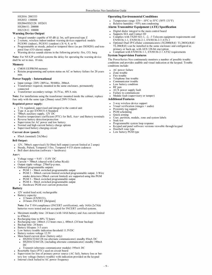
HS2016: 2083333HS2032: 1388888HS2064/HS2128: 1052631HS2064 E: 200000HS2128 E: 100000
Warning Device Outputl Integral sounder capable of 85 dB @ 3m, self-powered type Zl 2 remote, wireless indoor/outdoor warning devices supported: models
PGX901 (indoor), PGX911 (outdoor) (X=4, 8, or 9)l Programmable as steady, pulsed or temporal three (as per ISO8201) and tem-
poral four (CO alarm) outputl Warning device sounds alarms in the following priority: fire, CO, burgNote: For NFA2P certified systems the delay for operating the warning deviceshall be set to max. 10 min.Memoryl CMOS EEPROM memoryl Retains programming and system status on AC or battery failure for 20 years
min.Power Supply - Internationall Input ratings: 220V-240Vac, 50/60Hz, 200mAl Transformer required, mounted in the same enclosure, permanently
connectedl Transformer secondary ratings: 16.5Vac, 40VA min.Note: For installations using the transformer mounted inside the cabinet, replacefuse only with the same type (20mm) rated 250V/315mA.Regulated power supply:l 1.7A regulated, supervised and integral to the control unitl Type A as per EN50131-6 Standardl 700mA auxiliary supply, 12V DCl Positive temperature coefficient (PTC) for Bell, Aux+ and Battery terminalsl Reverse battery detection/protectionl Supervision for AC power and low batteryl Normal and high current battery charge optionsl Supervised battery charging circuitCurrent draw (panel):l 85mA (nominal) 2A(Max)Bell Output:l 12V, 700mA supervised (1k Ohm) bell output (current limited at 2 amps)l Steady, Pulsed, Temporal 3 fire, Temporal 4 CO alarm cadencesl Bell short detection (software + hardware)Aux+:l Voltage range = 9.6V - 13.8V DCl Current = 700mA (shared with Corbus R(ed))l Output ripple voltage: 270mVp-p max.l Onboard programmable outputs:
l PGM 1 - 50mA switched programmable outputl PGM 2 - 300mA current-limited switched programmable output. 2-Wire
smoke detectors (90mA current limited) are supported using this PGMl PGM 3 - 50mA switched programmable outputl PGM 4 - 50mA switched programmable outputl Hardware PGM over current protection
Batteryl 12V sealed lead acid, rechargeablel Battery capacity:
l 12 hours (EN50131),l 24 hours INCERT [Belgium]Note: For T 014 compliance (INCERT certification), only 14Ah (2x7Ah)batteries were tested and are accepted for INCERT certified systems.
l Maximum standby time: 24 hours (with 14Ah battery and Aux current limitedto 470mA)
l Recharging time to 80% 72 hoursl Recharging rate: 240mA (12 hours max.), 480mA (24 hour backup)l Backup time: 24 hoursl Battery lifespan: 3-5 yearsl Low battery trouble indication threshold 11.5VDCl Battery restore voltage 12.5Vl Main board current draw (battery only):
l HS2016/32/64/128 (no alternate communicator) standby 85mA DCl HS2016/32/64/128, (including alternate communicator) standby 190mA
DCl Transmit (alternate communicator module) 195mA DC
l Resettable fuses (PTC) used on circuit boardl Supervision for loss of primary power source (AC fail), battery loss or bat-
tery low voltage (battery trouble) with indication provided on the keypadl Internal clock locked to AC power frequency
Operating Environmental Conditionsl Temperature range: EN= -10°C to 55°C (50°F-131°F)l Relative humidity: <93% non condensingAlarm Transmitter Equipment (ATE) Specificationl Digital dialer integral to the main control boardl Supports SIA and Contact IDl Complies with TS203 021-1, -2, -3 Telecom equipment requirements and
EN50136-1-1, EN50136-2-1, EN50136-2-3 ATS 2l Optional Dual IP/Cellular communicators (3G2080(R)E/ TL2803G(R)E/
TL280(R)E) can be installed in the same enclosure and configured asprimary or back-up, with AES 128-bit encryption
l Compliant with EN50136-1-1, EN50136-2-1 ATS2 requirementsSystem Supervision FeaturesThe PowerSeries Neo continuously monitors a number of possible troubleconditions and provides audible and visual indication at the keypad. Troubleconditions include:l AC power failurel Zone troublel Fire troublel Telephone line troublel Communicator troublel Low battery conditionl RF jaml AUX power supply faultl Failure to communicatel Module fault (supervisory or tamper)Additional Featuresl 2-way wireless device supportl Visual verification (images + audio)l Proximity tag supportl PGM schedulingl Quick armingl User, partition, module, zone and system labelsl Soak testl Programmable system loop responsel Keypad and panel software versions viewable through keypadl Doorbell zone typel Low battery PGM type
- 9 -
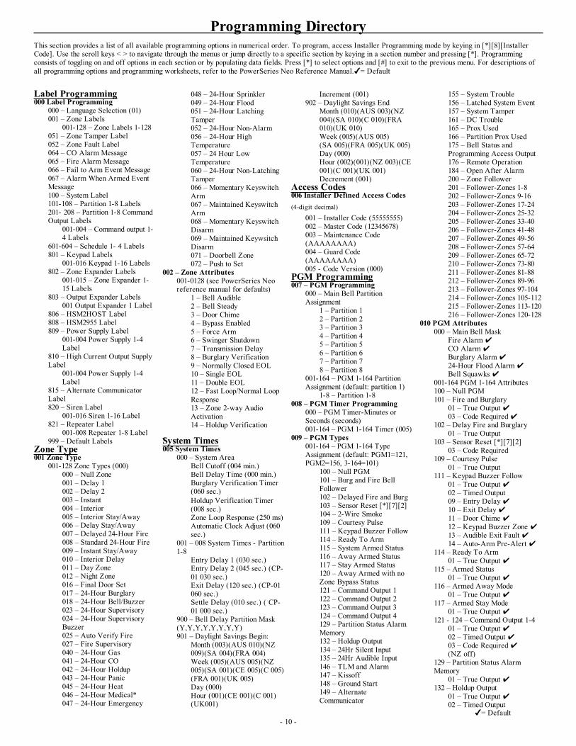
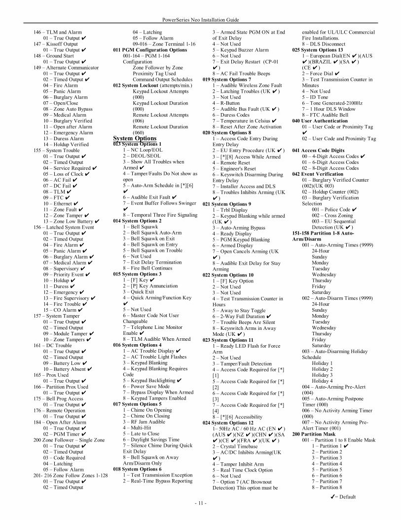
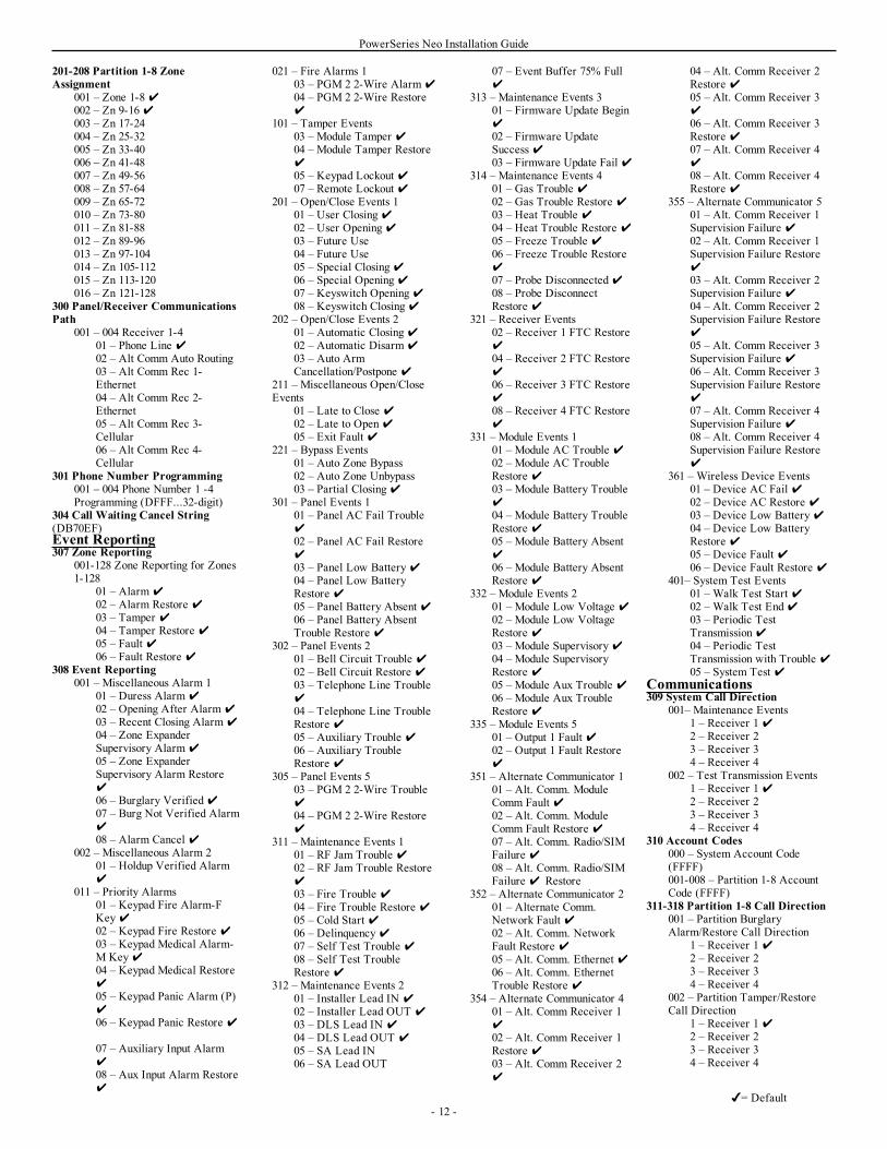
Programming DirectoryThis section provides a list of all available programming options in numerical order. To program, access Installer Programming mode by keying in [*][8][InstallerCode]. Use the scroll keys < > to navigate through the menus or jump directly to a specific section by keying in a section number and pressing [*]. Programmingconsists of toggling on and off options in each section or by populating data fields. Press [*] to select options and [#] to exit to the previous menu. For descriptions ofall programming options and programming worksheets, refer to the PowerSeries Neo Reference Manual.= Default
- 10 -
Label Programming000 Label Programming
000 – Language Selection (01)001 – Zone Labels
001-128 – Zone Labels 1-128051 – Zone Tamper Label052 – Zone Fault Label064 – CO Alarm Message065 – Fire Alarm Message066 – Fail to Arm Event Message067 – Alarm When Armed EventMessage100 – System Label101-108 – Partition 1-8 Labels201- 208 – Partition 1-8 CommandOutput Labels
001-004 – Command output 1-4 Labels
601-604 – Schedule 1- 4 Labels801 – Keypad Labels
001-016 Keypad 1-16 Labels802 – Zone Expander Labels
001-015 – Zone Expander 1-15 Labels
803 – Output Expander Labels001 Output Expander 1 Label
806 – HSM2HOST Label808 – HSM2955 Label809 – Power Supply Label
001-004 Power Supply 1-4Label
810 – High Current Output SupplyLabel
001-004 Power Supply 1-4Label
815 – Alternate CommunicatorLabel820 – Siren Label
001-016 Siren 1-16 Label821 – Repeater Label
001-008 Repeater 1-8 Label999 – Default Labels
Zone Type001 Zone Type
001-128 Zone Types (000)000 – Null Zone001 – Delay 1002 – Delay 2003 – Instant004 – Interior005 – Interior Stay/Away006 – Delay Stay/Away007 – Delayed 24-Hour Fire008 – Standard 24-Hour Fire009 – Instant Stay/Away010 – Interior Delay011 – Day Zone012 – Night Zone016 – Final Door Set017 – 24-Hour Burglary018 – 24-Hour Bell/Buzzer023 – 24-Hour Supervisory024 – 24-Hour SupervisoryBuzzer025 – Auto Verify Fire027 – Fire Supervisory040 – 24-Hour Gas041 – 24-Hour CO042 – 24-Hour Holdup043 – 24-Hour Panic045 – 24-Hour Heat046 – 24-Hour Medical*047 – 24-Hour Emergency
048 – 24-Hour Sprinkler049 – 24-Hour Flood051 – 24-Hour LatchingTamper052 – 24-Hour Non-Alarm056 – 24-Hour HighTemperature057 – 24 Hour LowTemperature060 – 24-Hour Non-LatchingTamper066 – Momentary KeyswitchArm067 – Maintained KeyswitchArm068 – Momentary KeyswitchDisarm069 – Maintained KeywsitchDisarm071 – Doorbell Zone072 – Push to Set
002 – Zone Attributes001-0128 (see PowerSeries Neoreference manual for defaults)
1 – Bell Audible2 – Bell Steady3 – Door Chime4 – Bypass Enabled5 – Force Arm6 – Swinger Shutdown7 – Transmission Delay8 – Burglary Verification9 – Normally Closed EOL10 – Single EOL11 – Double EOL12 – Fast Loop/Normal LoopResponse13 – Zone 2-way AudioActivation14 – Holdup Verification
System Times005 System Times
000 – System AreaBell Cutoff (004 min.)Bell Delay Time (000 min.)Burglary Verification Timer(060 sec.)Holdup Verification Timer(008 sec.)Zone Loop Response (250 ms)Automatic Clock Adjust (060sec.)
001 – 008 System Times - Partition1-8
Entry Delay 1 (030 sec.)Entry Delay 2 (045 sec.) (CP-01 030 sec.)Exit Delay (120 sec.) (CP-01060 sec.)Settle Delay (010 sec.) ( CP-01 000 sec.)
900 – Bell Delay Partition Mask(Y,Y,Y,Y,Y,Y,Y,Y)901 – Daylight Savings Begin:
Month (003)(AUS 010)(NZ009)(SA 004)(FRA 004)Week (005)(AUS 005)(NZ005)(SA 001)(CE 005)(C 005)(FRA 001)(UK 005)Day (000)Hour (001)(CE 001)(C 001)(UK001)
Increment (001)902 – Daylight Savings End
Month (010)(AUS 003)(NZ004)(SA 010)(C 010)(FRA010)(UK 010)Week (005)(AUS 005)(SA 005)(FRA 005)(UK 005)Day (000)Hour (002)(001)(NZ 003)(CE001)(C 001)(UK 001)Decrement (001)
Access Codes006 Installer Defined Access Codes(4-digit decimal)
001 – Installer Code (55555555)002 – Master Code (12345678)003 – Maintenance Code(AAAAAAAA)004 – Guard Code(AAAAAAAA)005 - Code Version (000)
PGM Programming007 – PGM Programming
000 – Main Bell PartitionAssignment
1 – Partition 12 – Partition 23 – Partition 34 – Partition 45 – Partition 56 – Partition 67 – Partition 78 – Partition 8
001-164 – PGM 1-164 PartitionAssignment (default: partition 1)
1-8 – Partition 1-8008 – PGM Timer Programming
000 – PGM Timer-Minutes orSeconds (seconds)001-164 – PGM 1-164 Timer (005)
009 – PGM Types001-164 – PGM 1-164 TypeAssignment (default: PGM1=121,PGM2=156, 3-164=101)
100 – Null PGM101 – Burg and Fire BellFollower102 – Delayed Fire and Burg103 – Sensor Reset [*][7][2]104 – 2-Wire Smoke109 – Courtesy Pulse111 – Keypad Buzzer Follow114 – Ready To Arm115 – System Armed Status116 – Away Armed Status117 – Stay Armed Status120 – Away Armed with noZone Bypass Status121 – Command Output 1122 – Command Output 2123 – Command Output 3124 – Command Output 4129 – Partition Status AlarmMemory132 – Holdup Output134 – 24Hr Silent Input135 – 24Hr Audible Input146 – TLM and Alarm147 – Kissoff148 – Ground Start149 – AlternateCommunicator
155 – System Trouble156 – Latched System Event157 – System Tamper161 – DC Trouble165 – Prox Used166 – Partition Prox Used175 – Bell Status andProgramming Access Output176 – Remote Operation184 – Open After Alarm200 – Zone Follower201 – Follower-Zones 1-8202 – Follower-Zones 9-16203 – Follower-Zones 17-24204 – Follower-Zones 25-32205 – Follower-Zones 33-40206 – Follower-Zones 41-48207 – Follower-Zones 49-56208 – Follower-Zones 57-64209 – Follower-Zones 65-72210 – Follower-Zones 73-80211 – Follower-Zones 81-88212 – Follower-Zones 89-96213 – Follower-Zones 97-104214 – Follower-Zones 105-112215 – Follower-Zones 113-120216 – Follower-Zones 120-128
010 PGM Attributes000 – Main Bell Mask
Fire AlarmCO AlarmBurglary Alarm24-Hour Flood AlarmBell Squawks
001-164 PGM 1-164 Attributes100 – Null PGM101 – Fire and Burglary
01 – True Output 03 – Code Required
102 – Delay Fire and Burglary01 – True Output
103 – Sensor Reset [*][7][2]03 – Code Required
109 – Courtesy Pulse01 – True Output
111 – Keypad Buzzer Follow01 – True Output 02 – Timed Output09 – Entry Delay10 – Exit Delay11 – Door Chime 12 – Keypad Buzzer Zone 13 – Audible Exit Fault 14 – Auto-Arm Pre-Alert
114 – Ready To Arm01 – True Output
115 – Armed Status01 – True Output
116 – Armed Away Mode01 – True Output
117 – Armed Stay Mode01 – True Output
121 - 124 – Command Output 1-401 – True Output 02 – Timed Output 03 – Code Required(NZ off)
129 – Partition Status AlarmMemory
01 – True Output 132 – Holdup Output
01 – True Output 02 – Timed Output
= Default
PowerSeries Neo Installation Guide
146 – TLM and Alarm01 – True Output
147 – Kissoff Output01 – True Output
148 – Ground Start01 – True Output
149 – Alternate Communicator01 – True Output 02 – Timed Output 04 – Fire Alarm05 – Panic Alarm06 – Burglary Alarm07 – Open/Close08 – Zone Auto Bypass09 – Medical Alarm10 – Burglary Verified11 – Open after Alarm12 – Emergency Alarm13 – Duress Alarm14 – Holdup Verified
155 – System Trouble01 – True Output 02 – Timed Output04 – Service Required05 – Loss of Clock06 – AC Fail 07 – DC Fail 08 – TLM09 – FTC 10 – Ethernet 11 – Zone Fault 12 – Zone Tamper 13 – Zone Low Battery
156 – Latched System Event01 – True Output 02 – Timed Output04 – Fire Alarm05 – Panic Alarm06 – Burglary Alarm07 – Medical Alarm08 – Supervisory09 – Priority Event 10 – Holdup11 – Duress 12 – Emergency13 – Fire Supervisory14 – Fire Trouble 15 – CO Alarm
157 – System Tamper01 – True Output 02 – Timed Output09 – Module Tamper 10 – Zone Tampers
161 – DC Trouble01 – True Output 02 – Timed Output09 – Battery Low 10 – Battery Absent
165 – Prox Used01 – True Output
166 – Partition Prox Used01 – True Output
175 – Bell Prog Access01 – True Output
176 – Remote Operation01 – True Output
184 – Open After Alarm01 – True Output 02 – PGM Timer
200 Zone Follower – Single Zone01 – True Output 02 – Timed Output03 – Code Required04 – Latching05 – Follow Alarm
201- 216 Zone Follow Zones 1-12801 – True Output 02 – Timed Output
04 – Latching05 – Follow Alarm09-016 – Zone Terminal 1-16
011 PGM Configuration Options001-164 – PGM 1-164Configuration
Zone Follower by ZoneProximity Tag UsedCommand Output Schedules
012 System Lockout (attempts/min.)Keypad Lockout Attempts(000)Keypad Lockout Duration(000)Remote Lockout Attempts(006)Remote Lockout Duration(060)
System Options013 System Options 1
1 – NC Loop/EOL2 – DEOL/SEOL3 – Show All Troubles whenArmed4 – Tamper/Faults Do Not show asopen5 – Auto-Arm Schedule in [*][6]6 – Audible Exit Fault 7 – Event Buffer Follows Swinger8 – Temporal Three Fire Signaling
014 System Options 21 – Bell Squawk2 – Bell Squawk Auto-Arm3 – Bell Squawk on Exit4 – Bell Squawk on Entry5 – Bell Squawk on Trouble6 – Not Used7 – Exit Delay Termination8 – Fire Bell Continues
015 System Options 31 – [F] Key2 – [P] Key Annunciation3 – Quick Exit4 – Quick Arming/Function Key5 – Not Used6 – Master Code Not UserChangeable7 – Telephone Line MonitorEnable 8 – TLM Audible When Armed
016 System Options 41 – AC Trouble Display2 – AC Trouble Light Flashes3 – Keypad Blanking4 – Keypad Blanking RequiresCode5 – Keypad Backlighting6 – Power Save Mode7 – Bypass Display When Armed8 – Keypad Tampers Enabled
017 System Options 51 – Chime On Opening2 – Chime On Closing3 – RF Jam Audible4 – Multi-Hit5 – Late to Close6 – Daylight Savings Time7 – Silence Chime During QuickExit Delay8 – Bell Squawk on AwayArm/Disarm Only
018 System Options 61 – Test Transmission Exception2 – Real-Time Bypass Reporting
3 – Armed State PGM ON at Endof Exit Delay4 – Not Used5 – Keypad Buzzer Alarm6 – Not Used7 – Exit Delay Restart (CP-01 )8 – AC Fail Trouble Beeps
019 System Options 71 – Audible Wireless Zone Fault2 – Latching Troubles (UK )3 – Not Used4 – R-Button5 – Audible Bus Fault (UK )6 – Duress Codes7 – Temperature in Celsius 8 – Reset After Zone Activation
020 System Options 81 – Access Code Entry DuringEntry Delay2 – EU Entry Procedure (UK )3 – [*][8] Access While Armed4 – Remote Reset5 – Engineer's Reset6 – Keyswitch Disarming DuringEntry Delay7 – Installer Access and DLS8 – Troubles Inhibits Arming (UK )
021 System Options 91 – Trbl Display2 – Keypad Blanking while armed(UK )3 – Auto-Arming Bypass4 – Ready Display5 – PGM Keypad Blanking6 – Armed Display7 – Open Cancels Arming (UK )8 – Audible Exit Delay for StayArming
022 System Options 101 – [F] Key Option2 – Not Used3 – Not Used4 – Test Transmission Counter inHours5 – Away to Stay Toggle6 – 2-Way Full Duration7 – Trouble Beeps Are Silent8 – Keyswitch Arms in AwayMode (UK )
023 System Options 111 – Ready LED Flash for ForceArm2 – Not Used3 – Tamper/Fault Detection4 – Access Code Required for [*][1]5 – Access Code Required for [*][2]6 – Access Code Required for [*][3]7 – Access Code Required for [*][4]8 – [*][6] Accessibility
024 System Options 121– 50Hz AC / 60 Hz AC (EN )(AUS )(NZ )(CHN )(SA )(CE )(FRA )(UK )2 – Crystal Timebase3 – AC/DC Inhibits Arming(UK )4 – Tamper Inhibit Arm5 – Real Time Clock Option6 – Not Used7 – Option 7 (AC BrownoutDetection) This option must be
enabled for UL/ULC CommercialFire Installations.8 – DLS Disconnect
025 System Options 131 – European Dial(EN )(AUS )(BRAZIL )(SA )(CE )2 – Force Dial 3 – Test Transmission Counter inMinutes4 – Not Used5 – ID Tone6 – Tone Generated-2100Hz7 – 1 Hour DLS Window8 – FTC Audible Bell
040 User Authentication01 – User Code or Proximity Tag02 – User Code and Proximity Tag
041 Access Code Digits00 – 4-Digit Access Codes 01 – 6-Digit Access Codes02 – 8-Digit Access Codes
042 Event Verification01 – Burglary Verified Counter(002)(UK 003)02 – Holdup Counter (002)03 – Burglary VerificationSelection
001 – Police Code 002 – Cross Zoning003 – EU SequentialDetection (UK )
151-158 Partition 1-8 Auto-Arm/Disarm
001 – Auto-Arming Times (9999)24-HourSundayMondayTuesdayWednesdayThursdayFridaySaturday
002 – Auto-Disarm Times (9999)24-HourSundayMondayTuesdayWednesdayThursdayFridaySaturday
003 – Auto-Disarming HolidaySchedule
Holiday 1Holiday 2Holiday 3Holiday 4
004 – Auto-Arming Pre-Alert(004)005 – Auto-Arming PostponeTimer (000)006 – No Activity Arming Timer(000)007 – No Activity Arming Pre-Alert Timer (001)
200 Partition Mask001 – Partition 1 to 8 Enable Mask
1 – Partition 12 – Partition 23 – Partition 34 – Partition 45 – Partition 56 – Partition 67 – Partition 78 – Partition 8
- 11 -= Default
PowerSeries Neo Installation Guide
201-208 Partition 1-8 ZoneAssignment
001 – Zone 1-8002 – Zn 9-16003 – Zn 17-24004 – Zn 25-32005 – Zn 33-40006 – Zn 41-48007 – Zn 49-56008 – Zn 57-64009 – Zn 65-72010 – Zn 73-80011 – Zn 81-88012 – Zn 89-96013 – Zn 97-104014 – Zn 105-112015 – Zn 113-120016 – Zn 121-128
300 Panel/Receiver CommunicationsPath
001 – 004 Receiver 1-401 – Phone Line 02 – Alt Comm Auto Routing03 – Alt Comm Rec 1-Ethernet04 – Alt Comm Rec 2-Ethernet05 – Alt Comm Rec 3-Cellular06 – Alt Comm Rec 4-Cellular
301 Phone Number Programming001 – 004 Phone Number 1 -4Programming (DFFF...32-digit)
304 Call Waiting Cancel String(DB70EF)Event Reporting307 Zone Reporting
001-128 Zone Reporting for Zones1-128
01 – Alarm02 – Alarm Restore 03 – Tamper 04 – Tamper Restore 05 – Fault 06 – Fault Restore
308 Event Reporting001 – Miscellaneous Alarm 1
01 – Duress Alarm02 – Opening After Alarm03 – Recent Closing Alarm04 – Zone ExpanderSupervisory Alarm05 – Zone ExpanderSupervisory Alarm Restore06 – Burglary Verified07 – Burg Not Verified Alarm08 – Alarm Cancel
002 – Miscellaneous Alarm 201 – Holdup Verified Alarm
011 – Priority Alarms01 – Keypad Fire Alarm-FKey02 – Keypad Fire Restore 03 – Keypad Medical Alarm-M Key04 – Keypad Medical Restore05 – Keypad Panic Alarm (P)06 – Keypad Panic Restore
07 – Auxiliary Input Alarm08 – Aux Input Alarm Restore
021 – Fire Alarms 103 – PGM 2 2-Wire Alarm04 – PGM 2 2-Wire Restore
101 – Tamper Events03 – Module Tamper 04 – Module Tamper Restore05 – Keypad Lockout 07 – Remote Lockout
201 – Open/Close Events 101 – User Closing02 – User Opening03 – Future Use04 – Future Use05 – Special Closing06 – Special Opening07 – Keyswitch Opening08 – Keyswitch Closing
202 – Open/Close Events 201 – Automatic Closing02 – Automatic Disarm03 – Auto ArmCancellation/Postpone
211 – Miscellaneous Open/CloseEvents
01 – Late to Close 02 – Late to Open05 – Exit Fault
221 – Bypass Events01 – Auto Zone Bypass02 – Auto Zone Unbypass03 – Partial Closing
301 – Panel Events 101 – Panel AC Fail Trouble02 – Panel AC Fail Restore03 – Panel Low Battery04 – Panel Low BatteryRestore 05 – Panel Battery Absent 06 – Panel Battery AbsentTrouble Restore
302 – Panel Events 201 – Bell Circuit Trouble 02 – Bell Circuit Restore 03 – Telephone Line Trouble04 – Telephone Line TroubleRestore 05 – Auxiliary Trouble 06 – Auxiliary TroubleRestore
305 – Panel Events 503 – PGM 2 2-Wire Trouble04 – PGM 2 2-Wire Restore
311 – Maintenance Events 101 – RF Jam Trouble 02 – RF Jam Trouble Restore03 – Fire Trouble 04 – Fire Trouble Restore 05 – Cold Start 06 – Delinquency07 – Self Test Trouble 08 – Self Test TroubleRestore
312 – Maintenance Events 201 – Installer Lead IN 02 – Installer Lead OUT 03 – DLS Lead IN 04 – DLS Lead OUT 05 – SA Lead IN06 – SA Lead OUT
07 – Event Buffer 75% Full
313 – Maintenance Events 301 – Firmware Update Begin02 – Firmware UpdateSuccess 03 – Firmware Update Fail
314 – Maintenance Events 401 – Gas Trouble 02 – Gas Trouble Restore 03 – Heat Trouble 04 – Heat Trouble Restore 05 – Freeze Trouble 06 – Freeze Trouble Restore07 – Probe Disconnected08 – Probe DisconnectRestore
321 – Receiver Events02 – Receiver 1 FTC Restore04 – Receiver 2 FTC Restore06 – Receiver 3 FTC Restore08 – Receiver 4 FTC Restore
331 – Module Events 101 – Module AC Trouble 02 – Module AC TroubleRestore 03 – Module Battery Trouble04 – Module Battery TroubleRestore 05 – Module Battery Absent06 – Module Battery AbsentRestore
332 – Module Events 201 – Module Low Voltage 02 – Module Low VoltageRestore 03 – Module Supervisory04 – Module SupervisoryRestore 05 – Module Aux Trouble 06 – Module Aux TroubleRestore
335 – Module Events 501 – Output 1 Fault 02 – Output 1 Fault Restore
351 – Alternate Communicator 101 – Alt. Comm. ModuleComm Fault 02 – Alt. Comm. ModuleComm Fault Restore 07 – Alt. Comm. Radio/SIMFailure 08 – Alt. Comm. Radio/SIMFailure Restore
352 – Alternate Communicator 201 – Alternate Comm.Network Fault 02 – Alt. Comm. NetworkFault Restore 05 – Alt. Comm. Ethernet 06 – Alt. Comm. EthernetTrouble Restore
354 – Alternate Communicator 401 – Alt. Comm Receiver 102 – Alt. Comm Receiver 1Restore 03 – Alt. Comm Receiver 2
04 – Alt. Comm Receiver 2Restore 05 – Alt. Comm Receiver 306 – Alt. Comm Receiver 3Restore 07 – Alt. Comm Receiver 408 – Alt. Comm Receiver 4Restore
355 – Alternate Communicator 501 – Alt. Comm Receiver 1Supervision Failure 02 – Alt. Comm Receiver 1Supervision Failure Restore03 – Alt. Comm Receiver 2Supervision Failure 04 – Alt. Comm Receiver 2Supervision Failure Restore05 – Alt. Comm Receiver 3Supervision Failure 06 – Alt. Comm Receiver 3Supervision Failure Restore07 – Alt. Comm Receiver 4Supervision Failure 08 – Alt. Comm Receiver 4Supervision Failure Restore
361 – Wireless Device Events01 – Device AC Fail 02 – Device AC Restore 03 – Device Low Battery04 – Device Low BatteryRestore 05 – Device Fault 06 – Device Fault Restore
401– System Test Events01 – Walk Test Start 02 – Walk Test End03 – Periodic TestTransmission04 – Periodic TestTransmission with Trouble 05 – System Test
Communications309 System Call Direction
001– Maintenance Events1 – Receiver 12 – Receiver 23 – Receiver 34 – Receiver 4
002 – Test Transmission Events1 – Receiver 12 – Receiver 23 – Receiver 34 – Receiver 4
310 Account Codes000 – System Account Code(FFFF)001-008 – Partition 1-8 AccountCode (FFFF)
311-318 Partition 1-8 Call Direction001 – Partition BurglaryAlarm/Restore Call Direction
1 – Receiver 12 – Receiver 23 – Receiver 34 – Receiver 4
002 – Partition Tamper/RestoreCall Direction
1 – Receiver 12 – Receiver 23 – Receiver 34 – Receiver 4
- 12 -= Default
PowerSeries Neo Installation Guide
003 – Partition Opening/ClosingCall Direction
1 – Receiver 12 – Receiver 23 – Receiver 34 – Receiver 4
350 Communicator Formats (04 -SIA)
001– Communicator Format -Receiver 1002– Communicator Format -Receiver 2003– Communicator Format -Receiver 3004– Communicator Format -Receiver 4
377 Communication Variables001 – Swinger Shutdown Attempts
– Alarms and Restore (003)(CP-01 002 sec.)– Tampers and Restore (003)– Maintenance and Restore(003)
002 – Communication Delays– Zone Delay (000 sec.)(CP-01 030 sec.)– AC Failure CommunicationDelay (030 min./hrs.)– TLM Trouble Delay (010sec. x 3)– WLS Zone Low BatteryTransmission Delay (007days)– Delinquency TransmissionDelay (030 hours/days)– Communications CancelWindow (000 (CP-01 005min.)
003 – Periodic Test TransmissionCycle (030 hrs./days)004 – Periodic Test TransmissionTime of Day (9999)011 – Maximum Dialing Attempts(005)012 – PSTN Delay (003 sec.)013 – Delay Between ForceAttempts (020 sec.)014 – Post Dial Wait forHandshake (040 sec.)015 – T-Link Wait for Ack (060sec.)016 – IP/Cellular Fault CheckTimer (010 )
380 Communicator Option 11 – Communications Enabled2 – Restore on Bell Timeout3 – Pulse Dialing4 – Pulse Dial After 5th Attempt5 – Parallel Communications6 – Alternate Dial 7 – Reduced Dialing Attempts8 – Activity Delinquency
381 Communicator Option 21 – Keypad Ringback2 – Bell Ringback4 – Closing Confirmation8 – Communications Priority
382 Communicator Option 31 – Test Transmission Reciever2 – Walk Test Communication(UK )4 – Call Waiting Cancel5 – Alternate CommunicatorEnable6 – AC Failure TX in Hours8 – Tamper Limit (UK )
383 Communicator Option 4
1 – Phone Number Account Code2 – 6-Digit Account Code5 – Communicate FTC Events
384 Communicator Backup Options2 – Backup Options - Receiver 23 – Backup Options - Receiver 34 – Backup Options - Receiver 4
385 Audio Module Talk/Listen Mask1 – Talk/Listen on Phone Number12 – Talk/Listen on Phone Number23 – Talk/Listen on Phone Number34 – Talk/Listen on Phone Number4
DLS Programming401 DLS/SA Options
1 – Double Call (C )2 – User Enables DLS (C off)3 – DLS Callback4 – User Call Up6 – Panel Call-Up and Baud Rate7 – Alt. Comm DLS
402 DLS Phone NumberProgramming (31-digit decimal)403 DLS Access Code (default isbased on model)
HS2128 Models (212800)HS2064 Models (206400)HS2032 Models (203200)HS2016 Models (201600)
404 DLS/SA Panel ID (default isbased on model)
HS2128 Models (2128000000)HS2064 Models (2064000000)HS2032 Models (2032000000)HS2016 Models (2016000000)
405 PSTN Double Call Timer (060sec.)406 PSTN Number of Rings toAnswer On (000)(TIS 008)407 SA Access Code (FFFFFF)410 Automatic DLS Options
001 – Automatic DLS ToggleOptions
1 – Periodic DLS3 – DLS on Event Buffer 75%Full8 – DLS On ProgrammingChange
002 – Periodic DLS Days (000days)003 – Periodic DLS Time (0000)007 – Delay Call Window
– Delay Call Window Start(0000)– Delay Call Window End(0000)
560 Virtual Inputs (000)001 - 032 – Virtual Input 1-32
Schedule Programming601-604 Programming Schedule 1-4
101 – Interval 1 Start Time (0000)102 – Interval 1 End Time (0000)103 – Interval 1 Days Assignment
01 – Sunday02 – Monday03 – Tuesday04 – Wednesday05 – Thursday06 – Friday07 – Saturday
104 – Interval 1 HolidayAssignment
09 – Holiday 110 – Holiday 211 – Holiday 3
12 – Holiday 4201 – Interval 2 Start Time (0000)202 – Interval 2 End Time (0000)203 – Interval 2 Days Assignment
01 – Sunday02 – Monday03 – Tuesday04 – Wednesday05 – Thursday06 – Friday07 – Saturday
204 – Interval 2 HolidayAssignment
09 – Holiday 110 – Holiday 211 – Holiday 312 – Holiday 4
301 – Interval 3 Start Time (0000)302 – Interval 3 End Time (0000)303 – Interval 3 Days Assignment
01 – Sunday02 – Monday03 – Tuesday04 – Wednesday05 – Thursday06 – Friday07 – Saturday
304 – Interval 3 HolidayAssignment
09 – Holiday 110 – Holiday 211 – Holiday 312 – Holiday 4 201 – Interval2 Start Time (0000)
402 – Interval 4 End Time (0000)403 – Interval 4 Days Assignment
01 – Sunday02 – Monday03 – Tuesday04 – Wednesday05 – Thursday06 – Friday07 – Saturday
404 – Interval 4 HolidayAssignment
09 – Holiday 110 – Holiday 211 – Holiday 312 – Holiday 4
711-714 Holiday Group 1-4001 – 099 Holiday Group 1-4 Date1-99 (000000, MMDDYY)
Audio Station Programming802 Audio Station Assignment
001 - 128 – Station Assignment 1 -128 (00)600 – 2-Way Audio Trigger Option1
01 – Tampers03 – [A] Key Alarm04 – [P] Key Alarm05 – Duress Alarm06 – Opening After Alarm07 – Future Use08 – Zone Supervision Alarm
603 – 2-Way Audio Control Option1
01 – Future Use02 – Listen to all zones /Listen to zones in alarm03 – Future Use04 – Siren Active During 2-Way Audio05 – Hang-Up Auto Detection06 – User Call-In07 – Future Use08 – 2-Way Audio Initiated byCS
605 – Record Options
01 – Audio Capture Enable 02 – Erase on FTC
606 – Audio Station RecordControl Option 1
01 – Audio Station 1 Record02 – Audio Station 2 Record03 – Audio Station 3 Record04 – Audio Station 4 Record
610 – Call Back / RecoveryWindow Duration (05)611 – Call Back Acknowledgecode (9999)612 – Answering Machine Bypass(00)613 – Double Call Timer (030)614 – Number of Rings to Answer(00)615 – Audio Duration (90 sec.)616 – Record Time (105 sec.)617 – Erase Timer (15 min.)606 – Audio Station TamperOption 1
01 – Audio Station 1 Tamper02 – Audio Station 2 Tamper03 – Audio Station 3 Tamper04 – Audio Station 4 Tamper
Wireless Programming804 Wireless Programming
000 – WLS Device EnrollmentZones (3-digit decimal)Zone Type (2-digit decimal)Partition AssignmentZone Label (LCD only)WLS KeysPartition AssignmentUser AssignmentSirensPartition AssignmentSiren Label (LCD only)KeypadsKeypad AssignmentKeypad Label (LCD only)RepeatersRepeater Label (LCD only)
001 - 128 – Configure WirelessZones
Refer to the installation instructionsprovided with the HSM2Host for morewireless programming options.850 Cellular Signal Strength851 Alternate CommunicatorProgrammingRefer to the installation instructionsprovided with the alternatecommunicator for details.Keypad Programming860 Keypad Slot Number861-876 Keypad Programming
000 – Keypad Partition Mask00 – Global Keypad01 – Partition 102 – Partition 203 – Partition 304 – Partition 405 – Partition 506 – Partition 607 – Partition 708 – Partition 8
001 – Function Key 1 ()002 – Function Key 2 ()003 – Function Key 3 (06)004 – Function Key 4 (22)005 – Function Key 5 ()
- 13 -= Default
PowerSeries Neo Installation Guide
00 – Null Key02 – Instant Stay Arm03 – Stay Arm04 – Away Arm05 – No Entry Arm06 – Chime On/Off07 – System Test09 – Night Arm12 – Global Stay Arm13 – Global Away Arm14 – Global Disarming16 – Quick Exit17 – Arm Interior21-24 – Command Output 1-429 – Bypass Group Recall31 – Local PGM Activate32 – Bypass Mode33 – Bypass recall34 – User Programming35 – User Functions37 – Time/Date Programming39 – Trouble Display40 – Alarm Memory61-68 – Partition Select 1-8
011 – Keypad I/O (000)012 – Local PGM Output Timer
Pulse Time (00 minutes)Pulse Time (05 sec.)
021 – Keypad Option 11 – [F] Key Enabled2 – [M] Key Enabled3 – [P] Key Enabled4 – Display Code or X's
022 – Keypad Option 21 – Local Clock Display2 – Local Clock Display 24 Hour3 – Auto Alarm Scroll 5 – Power LED Option6 – Power LED AC Present 7 – Alarms Displayed if Armed8 – Auto Scroll Open Zones
023 – Keypad Option 31 – Armed LED Power Save*2 – Keypad Show Arm Mode *3 – 5th Terminal is PGMOutput/Zone4 – Prox Tag Arm/Disarm7 – Local Display of Temp.8 – Low Temperature Warning
030 – LCD Message (16 x 2 hex )031 – Download LCD MessageDuration (000)041 – Indoor Temperature Zone Entry(000)042 – Outdoor Temperature Zone Entry(000)101-228 – Door Chime Sound-Zone 1-128
00 – Disabled01 – 6 beeps 02 – "Bing-Bong" Sound03 – "Ding-Dong" Sound04 – Alarm Tone05 – Zone Name
899 Template Programming– 5-Digit Template Code (5-digitdecimal)– Central Station TelephoneNumber (32-digit decimal)– Central Station Account Code(4/6-digit decimal)– Partition Account Code (4-digitdecimal)– DLS Access Code (6-digitdecimal)– Partition Entry Delay (000-255sec.)– Partition Exit Delay (000-255sec.)
– Installer CodeSystem Information andTesting900 System Information
000 – Control Panel Version001- 016 – Keypad 1-16 VersionInfo101-116 – 8-HSM2108 1-16Version Info201-216 – HSM2208 VersionInformation460 – Alternate Communicator461 – HSM2HOST Version Info481 – HSM2955 Version Info501 – 504 HSM2300 1-4 VersionInfo521 – 524 HSM2204 1-4 VersionInfo
901 Installer Walk TestModule Programming902 Add/Remove Modules
000 – Auto-Enroll All Modules001 – Enroll Modules002 – Slot Assignment003 – Edit Module Slot Assignment101 – Delete Keypads102 – Delete HSM2108103 – Delete HSM2208106 – Delete HSM2HOST108 – Delete HSM2955109 – Delete HSM2300110 – Delete HSM2204
903 Confirm Modules000 – View All Modules101 – Keypads102 – HSM2108103 – HSM2208106 – HSM2HOST108 – Confirm HSM2955109 – HSM2300110 – HSM2204
904 Wireless Placement Test001-128 – Placement Test Zones1-128521-528 – Placement TestRepeaters 1-28551-566 – Placement Test Sirens1-16601-632 – Placement TestWireless Keys 1-32701-716 – Placement TestWireless Keypads 1-16
912 Soak Test000 – Zone Soak Test DurationDefault: 014001-128 – Zone Soak Test - Zones1-128
Battery Settings982 Battery Settings
000– Panel Battery Settings01– Panel High ChargeCurrent (SA )(FRA )(UK )
010 – HSM2204 Battery Settings01 – HSM2204 1 High ChargeCurrent (SA )(FRA )(UK )02 – HSM2204 2 High ChargeCurrent (SA )(FRA )(UK )03 – HSM2204 3 High ChargeCurrent (SA )(FRA )(UK )04 – HSM2204 4 High ChargeCurrent (SA )(FRA )(UK )
020 – HSM2300 Battery Settings01 – HSM2300 1 Charge(SA )(FRA )(UK )
02 – HSM2300 2 Charge(SA )(FRA )(UK )03 – HSM2300 3 Charge(SA )(FRA )(UK )04 – HSM2300 4 Charge(SA )(FRA )(UK )
Defaults989 Default Master Code990 Installer Lockout Enable/Disable991 Default Keypads
901-916 – Default Keypad 1-16999 – Default all Keypads
993 Default Alt Comm996 Default HSM2HOST998 Default HSM2955999 Default System* Wireless keypads only
- 14 -= Default
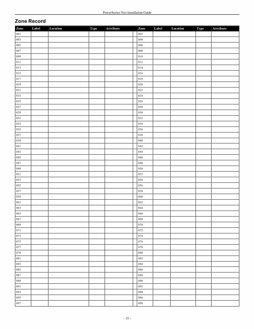
PowerSeries Neo Installation Guide
Zone RecordZone Label Location Type Attribute Zone Label Location Type Attribute001 002
003 004
005 006
007 008
009 010
011 012
013 014
015 016
017 018
019 020
021 022
023 024
025 026
027 028
029 030
031 032
033 034
035 036
037 038
039 040
041 042
043 044
045 046
047 048
049 050
051 052
053 054
055 056
057 058
059 060
061 062
063 064
065 066
067 068
069 070
071 072
073 074
075 076
077 078
079 080
081 082
083 084
085 086
087 088
089 090
091 092
093 094
095 096
097 098
- 15 -
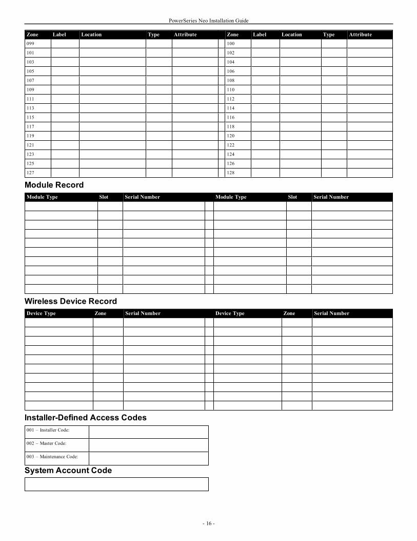
PowerSeries Neo Installation Guide
Zone Label Location Type Attribute Zone Label Location Type Attribute099 100
101 102
103 104
105 106
107 108
109 110
111 112
113 114
115 116
117 118
119 120
121 122
123 124
125 126
127 128
Module RecordModule Type Slot Serial Number Module Type Slot Serial Number
Wireless Device RecordDevice Type Zone Serial Number Device Type Zone Serial Number
Installer-Defined Access Codes001 – Installer Code:
002 – Master Code:
003 – Maintenance Code:
System Account Code
- 16 -
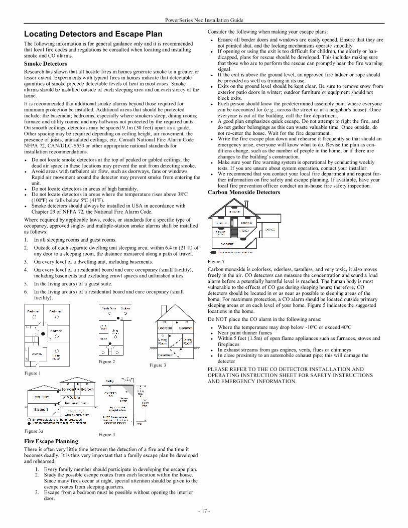
PowerSeries Neo Installation Guide
Locating Detectors and Escape PlanThe following information is for general guidance only and it is recommendedthat local fire codes and regulations be consulted when locating and installingsmoke and CO alarms.Smoke DetectorsResearch has shown that all hostile fires in homes generate smoke to a greater orlesser extent. Experiments with typical fires in homes indicate that detectablequantities of smoke precede detectable levels of heat in most cases. Smokealarms should be installed outside of each sleeping area and on each storey of thehome.It is recommended that additional smoke alarms beyond those required forminimum protection be installed. Additional areas that should be protectedinclude: the basement; bedrooms, especially where smokers sleep; dining rooms;furnace and utility rooms; and any hallways not protected by the required units.On smooth ceilings, detectors may be spaced 9.1m (30 feet) apart as a guide.Other spacing may be required depending on ceiling height, air movement, thepresence of joists, uninsulated ceilings, etc. Consult National Fire Alarm CodeNFPA 72, CAN/ULC-S553 or other appropriate national standards forinstallation recommendations.l Do not locate smoke detectors at the top of peaked or gabled ceilings; the
dead air space in these locations may prevent the unit from detecting smoke.l Avoid areas with turbulent air flow, such as doorways, fans or windows.
Rapid air movement around the detector may prevent smoke from entering theunit.
l Do not locate detectors in areas of high humidity.l Do not locate detectors in areas where the temperature rises above 38ºC
(100ºF) or falls below 5ºC (41ºF).l Smoke detectors should always be installed in USA in accordance with
Chapter 29 of NFPA 72, the National Fire Alarm Code.Where required by applicable laws, codes, or standards for a specific type ofoccupancy, approved single- and multiple-station smoke alarms shall be installedas follows:1. In all sleeping rooms and guest rooms.2. Outside of each separate dwelling unit sleeping area, within 6.4 m (21 ft) of
any door to a sleeping room, the distance measured along a path of travel.3. On every level of a dwelling unit, including basements.4. On every level of a residential board and care occupancy (small facility),
including basements and excluding crawl spaces and unfinished attics.5. In the living area(s) of a guest suite.6. In the living area(s) of a residential board and care occupancy (small
facility).
Figure 1
Figure 2Figure 3
Figure 3aFigure 4
Fire Escape PlanningThere is often very little time between the detection of a fire and the time itbecomes deadly. It is thus very important that a family escape plan be developedand rehearsed.
1. Every family member should participate in developing the escape plan.2. Study the possible escape routes from each location within the house.
Since many fires occur at night, special attention should be given to theescape routes from sleeping quarters.
3. Escape from a bedroom must be possible without opening the interiordoor.
Consider the following when making your escape plans:l Ensure all border doors and windows are easily opened. Ensure that they are
not painted shut, and the locking mechanisms operate smoothly.l If opening or using the exit is too difficult for children, the elderly or han-
dicapped, plans for rescue should be developed. This includes making surethat those who are to perform the rescue can promptly hear the fire warningsignal.
l If the exit is above the ground level, an approved fire ladder or rope shouldbe provided as well as training in its use.
l Exits on the ground level should be kept clear. Be sure to remove snow fromexterior patio doors in winter; outdoor furniture or equipment should notblock exits.
l Each person should know the predetermined assembly point where everyonecan be accounted for (e.g., across the street or at a neighbor's house). Onceeveryone is out of the building, call the fire department.
l A good plan emphasizes quick escape. Do not attempt to fight the fire, anddo not gather belongings as this can waste valuable time. Once outside, donot re-enter the house. Wait for the fire department.
l Write the fire escape plan down and rehearse it frequently so that should anemergency arise, everyone will know what to do. Revise the plan as con-ditions change, such as the number of people in the home, or if there arechanges to the building’s construction.
l Make sure your fire warning system is operational by conducting weeklytests. If you are unsure about system operation, contact your installer.
l We recommend that you contact your local fire department and request fur-ther information on fire safety and escape planning. If available, have yourlocal fire prevention officer conduct an in-house fire safety inspection.
Carbon Monoxide Detectors
Figure 5
Carbon monoxide is colorless, odorless, tasteless, and very toxic, it also movesfreely in the air. CO detectors can measure the concentration and sound a loudalarm before a potentially harmful level is reached. The human body is mostvulnerable to the effects of CO gas during sleeping hours; therefore, COdetectors should be located in or as near as possible to sleeping areas of thehome. For maximum protection, a CO alarm should be located outside primarysleeping areas or on each level of your home. Figure 5 indicates the suggestedlocations in the home.Do NOT place the CO alarm in the following areas:l Where the temperature may drop below -10ºC or exceed 40ºCl Near paint thinner fumesl Within 5 feet (1.5m) of open flame appliances such as furnaces, stoves and
fireplacesl In exhaust streams from gas engines, vents, flues or chimneysl In close proximity to an automobile exhaust pipe; this will damage the
detectorPLEASE REFER TO THE CO DETECTOR INSTALLATION ANDOPERATING INSTRUCTION SHEET FOR SAFETY INSTRUCTIONSAND EMERGENCY INFORMATION.
- 17 -
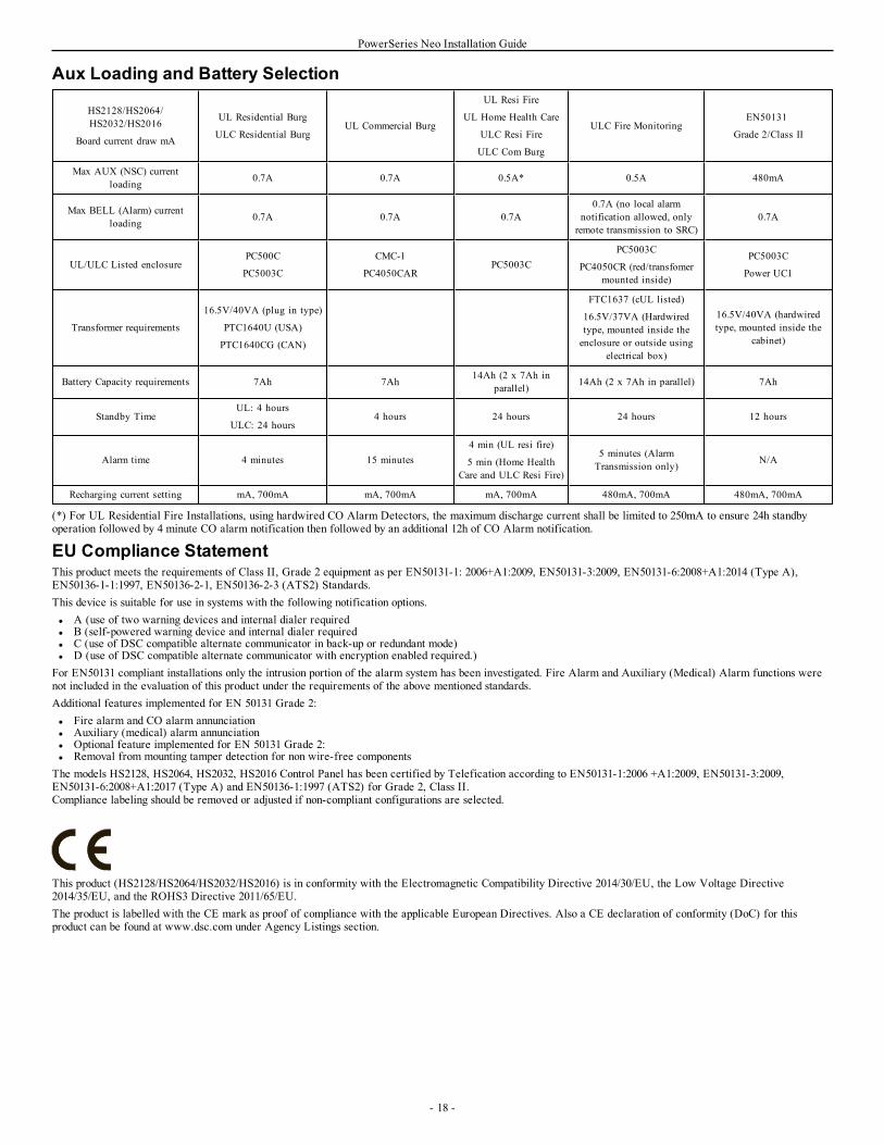
PowerSeries Neo Installation Guide
Aux Loading and Battery Selection
HS2128/HS2064/HS2032/HS2016
Board current draw mA
UL Residential Burg
ULC Residential BurgUL Commercial Burg
UL Resi Fire
UL Home Health Care
ULC Resi Fire
ULC Com Burg
ULC Fire MonitoringEN50131
Grade 2/Class II
Max AUX (NSC) currentloading 0.7A 0.7A 0.5A* 0.5A 480mA
Max BELL (Alarm) currentloading 0.7A 0.7A 0.7A
0.7A (no local alarmnotification allowed, onlyremote transmission to SRC)
0.7A
UL/ULC Listed enclosurePC500C
PC5003C
CMC-1
PC4050CARPC5003C
PC5003C
PC4050CR (red/transfomermounted inside)
PC5003C
Power UC1
Transformer requirements
16.5V/40VA (plug in type)
PTC1640U (USA)
PTC1640CG (CAN)
FTC1637 (cUL listed)
16.5V/37VA (Hardwiredtype, mounted inside theenclosure or outside using
electrical box)
16.5V/40VA (hardwiredtype, mounted inside the
cabinet)
Battery Capacity requirements 7Ah 7Ah 14Ah (2 x 7Ah inparallel) 14Ah (2 x 7Ah in parallel) 7Ah
Standby TimeUL: 4 hours
ULC: 24 hours4 hours 24 hours 24 hours 12 hours
Alarm time 4 minutes 15 minutes4 min (UL resi fire)
5 min (Home HealthCare and ULC Resi Fire)
5 minutes (AlarmTransmission only) N/A
Recharging current setting mA, 700mA mA, 700mA mA, 700mA 480mA, 700mA 480mA, 700mA
(*) For UL Residential Fire Installations, using hardwired CO Alarm Detectors, the maximum discharge current shall be limited to 250mA to ensure 24h standbyoperation followed by 4 minute CO alarm notification then followed by an additional 12h of CO Alarm notification.
EU Compliance StatementThis product meets the requirements of Class II, Grade 2 equipment as per EN50131-1: 2006+A1:2009, EN50131-3:2009, EN50131-6:2008+A1:2014 (Type A),EN50136-1-1:1997, EN50136-2-1, EN50136-2-3 (ATS2) Standards.This device is suitable for use in systems with the following notification options.l A (use of two warning devices and internal dialer requiredl B (self-powered warning device and internal dialer requiredl C (use of DSC compatible alternate communicator in back-up or redundant mode)l D (use of DSC compatible alternate communicator with encryption enabled required.)For EN50131 compliant installations only the intrusion portion of the alarm system has been investigated. Fire Alarm and Auxiliary (Medical) Alarm functions werenot included in the evaluation of this product under the requirements of the above mentioned standards.Additional features implemented for EN 50131 Grade 2:l Fire alarm and CO alarm annunciationl Auxiliary (medical) alarm annunciationl Optional feature implemented for EN 50131 Grade 2:l Removal from mounting tamper detection for non wire-free componentsThe models HS2128, HS2064, HS2032, HS2016 Control Panel has been certified by Telefication according to EN50131-1:2006 +A1:2009, EN50131-3:2009,EN50131-6:2008+A1:2017 (Type A) and EN50136-1:1997 (ATS2) for Grade 2, Class II.Compliance labeling should be removed or adjusted if non-compliant configurations are selected.
This product (HS2128/HS2064/HS2032/HS2016) is in conformity with the Electromagnetic Compatibility Directive 2014/30/EU, the Low Voltage Directive2014/35/EU, and the ROHS3 Directive 2011/65/EU.The product is labelled with the CE mark as proof of compliance with the applicable European Directives. Also a CE declaration of conformity (DoC) for thisproduct can be found at www.dsc.com under Agency Listings section.
- 18 -
PowerSeries Neo Installation Guide
UK Compliance StatementIn the UK this product is suitable for use in systems installed to conform to PD6662:2017 at Grade 2 and environmental class 2 with the following notificationoptions: A, B, C, D.
The CIE and notification equipment should be located and supervised to minimize therisk of vandalism or sabotage. It is preferable for the CIE, signaling and networkequipment to be located in an area where a confirmed activation will be generated.
HS2128, HS2064, HS2032, HS2016 are compliant with criteria for sequentiallyconfirmed intruder alarm systems as per Standard BS8243:2010+A1:2014.
For an alarm condition to be regarded as sequentially confirmed:
a) The HS2128, HS2064, HS2032, HS2016 should be configured so that at least twoseparate alarm conditions are reported, each originating from an independent detectorwithin the confirmation time; Section [042] option 003 (Sequential Detection), section[005]>[000], Burglary Verification Timer set to a value between 30 and 60.
b) The two detectors should either be of:
1) different technologies which are permitted to have overlapping areas of coverage; or
2) the same single technology and not have overlapping areas of coverage.
To be regarded as independent, each detector should be configured to report alarmconditions separately to the HS2128, HS2064, HS2032, HS2016.
The HS2128, HS2064, HS2032, HS2016 are capable of supporting the completion of thefull setting procedure by one of the following methods:
a) push button switch mounted outside the supervised premises. Instructions to beprovided for the zone type to be programmed for the key arming; or
b) protective switch (i.e., door contact) fitted to the final exit door of the alarmedpremises or area. Use zone type 016 (Final Door Set) for the final exit door.
In this case the setting procedure is a two-stage process of initiating the settingprocedure within the supervised premises (e.g., using wireless key PG8929, PG8939,PG8938, PG8949 or user code) followed by completion of setting by one of the twomethods described above.
This prohibits the use of a timed exit procedure.
If a protective switch (i.e. door contact) is used as the method of completion of setting,then the keypad should be sited near to the final exit door so that the IAS can be unsetpromptly. Where appropriate, additional internal audible indications (PG8911 indoorsirens) should be provided so that persons within a building are informed that theHS2128, HS2064, HS2032, HS2016 are due to be set. Additional keypads should beprovided, where appropriate, so that if the alarm panel is set there are means availablelocally within the supervised premises to unset the system.
HS2128, HS2064, HS2032, HS2016 are capable of supporting the following unsettingmethods in accordance with BS8243:
6.4.2 Prevention of entry to the supervised premises before the HS2128, HS2064,HS2032, HS2016 are unset. Unsetting using PG8929,PG8939, PG8938, PG8949wireless key before entering the supervised premises causes or permits the initial entrydoor to be unlocked. Program PGM1 or PGM2 in Section [009] to activate when systemis disarmed and release the mag-lock on the entry door.
- 19 -
PowerSeries Neo Installation Guide
Limited WarrantyDigital Security Controls warrants the original purchaser that for a period of twelvemonths from the date of purchase, the product shall be free of defects in materials andworkmanship under normal use. During the warranty period, Digital Security Controlsshall, at its option, repair or replace any defective product upon return of the product toits factory, at no charge for labour and materials. Any replacement and/or repaired partsare warranted for the remainder of the original warranty or ninety (90) days, whichever islonger. The original purchaser must promptly notify Digital Security Controls in writingthat there is defect in material or workmanship, such written notice to be received in allevents prior to expiration of the warranty period. There is absolutely no warranty onsoftware and all software products are sold as a user license under the terms of thesoftware license agreement included with the product. The Customer assumes allresponsibility for the proper selection, installation, operation and maintenance of anyproducts purchased from DSC. Custom products are only warranted to the extent thatthey do not function upon delivery. In such cases, DSC can replace or credit at itsoption.
International WarrantyThe warranty for international customers is the same as for any customer within Canadaand the United States, with the exception that Digital Security Controls shall not beresponsible for any customs fees, taxes, or VAT that may be due.
Warranty ProcedureTo obtain service under this warranty, please return the item(s) in question to the pointof purchase. All authorized distributors and dealers have a warranty program. Anyonereturning goods to Digital Security Controls must first obtain an authorization number.Digital Security Controls will not accept any shipment whatsoever for which priorauthorization has not been obtained.
Conditions to Void WarrantyThis warranty applies only to defects in parts and workmanship relating to normal use.It does not cover:
ll damage incurred in shipping or handling;l damage caused by disaster such as fire, flood, wind, earthquake or lightning;l damage due to causes beyond the control of Digital Security Controls such as
excessive voltage, mechanical shock or water damage;l damage caused by unauthorized attachment, alterations, modifications or foreign
objects;l damage caused by peripherals (unless such peripherals were supplied by Digital
Security Controls Ltd.);l defects caused by failure to provide a suitable installation environment for the
products;l damage caused by use of the products for purposes other than those for which it
was designed;l damage from improper maintenance;l damage arising out of any other abuse, mishandling or improper application of the
products.
Items Not Covered by WarrantyIn addition to the items which void the Warranty, the following items shall not becovered by Warranty: (i) freight cost to the repair centre; (ii) products which are notidentified with DSC's product label and lot number or serial number; (iii) productsdisassembled or repaired in such a manner as to adversely affect performance or preventadequate inspection or testing to verify any warranty claim. Access cards or tagsreturned for replacement under warranty will be credited or replaced at DSC's option.Products not covered by this warranty, or otherwise out of warranty due to age, misuse,or damage shall be evaluated, and a repair estimate shall be provided. No repair workwill be performed until a valid purchase order is received from the Customer and aReturn Merchandise Authorization number (RMA) is issued by DSC's Customer Service.
Digital Security Controls Ltd.’s liability for failure to repair the product under thiswarranty after a reasonable number of attempts will be limited to a replacement of theproduct, as the exclusive remedy for breach of warranty. Under no circumstances shallDigital Security Controls be liable for any special, incidental, or consequential damagesbased upon breach of warranty, breach of contract, negligence, strict liability, or anyother legal theory. Such damages include, but are not limited to, loss of profits, loss ofthe product or any associated equipment, cost of capital, cost of substitute orreplacement equipment, facilities or services, down time, purchaser’s time, the claims ofthird parties, including customers, and injury to property. The laws of somejurisdictions limit or do not allow the disclaimer of consequential damages. If the lawsof such a jurisdiction apply to any claim by or against DSC, the limitations anddisclaimers contained here shall be to the greatest extent permitted by law. Some statesdo not allow the exclusion or limitation of incidental or consequential damages, so thatthe above may not apply to you.
Disclaimer of WarrantiesThis warranty contains the entire warranty and shall be in lieu of any and all otherwarranties, whether expressed or implied (including all implied warranties ofmerchantability or fitness for a particular purpose) and of all other obligations orliabilities on the part of Digital Security Controls. Digital Security Controls neither
assumes responsibility for, nor authorizes any other person purporting to act on itsbehalf to modify or to change this warranty, nor to assume for it any other warranty orliability concerning this product. This disclaimer of warranties and limited warranty aregoverned by the laws of the province of Ontario, Canada.
WARNING: Digital Security Controls recommends that the entire system be completelytested on a regular basis. However, despite frequent testing, and due to, but not limitedto, criminal tampering or electrical disruption, it is possible for this product to fail toperform as expected.
Out of Warranty RepairsDigital Security Controls will at its option repair or replace out-of-warranty productswhich are returned to its factory according to the following conditions. Anyonereturning goods to Digital Security Controls must first obtain an authorization number.Digital Security Controls will not accept any shipment whatsoever for which priorauthorization has not been obtained.
Products which Digital Security Controls determines to be repairable will be repairedand returned. A set fee which Digital Security Controls has predetermined and whichmay be revised from time to time, will be charged for each unit repaired.
Products which Digital Security Controls determines not to be repairable will bereplaced by the nearest equivalent product available at that time. The current marketprice of the replacement product will be charged for each replacement unit.
WARNING - READ CAREFULLYNote to InstallersThis warning contains vital information. As the only individual in contact with systemusers, it is your responsibility to bring each item in this warning to the attention of theusers of this system.
System FailuresThis system has been carefully designed to be as effective as possible. There arecircumstances, however, involving fire, burglary, or other types of emergencies where itmay not provide protection. Any alarm system of any type may be compromiseddeliberately or may fail to operate as expected for a variety of reasons. Some but not allof these reasons may be:
Inadequate InstallationA security system must be installed properly in order to provide adequate protection.Every installation should be evaluated by a security professional to ensure that allaccess points and areas are covered. Locks and latches on windows and doors must besecure and operate as intended. Windows, doors, walls, ceilings and other buildingmaterials must be of sufficient strength and construction to provide the level ofprotection expected. A reevaluation must be done during and after any constructionactivity. An evaluation by the fire and/or police department is highly recommended ifthis service is available.
Criminal KnowledgeThis system contains security features which were known to be effective at the time ofmanufacture. It is possible for persons with criminal intent to develop techniques whichreduce the effectiveness of these features. It is important that a security system bereviewed periodically to ensure that its features remain effective and that it be updatedor replaced if it is found that it does not provide the protection expected.
Access by IntrudersIntruders may enter through an unprotected access point, circumvent a sensing device,evade detection by moving through an area of insufficient coverage, disconnect awarning device, or interfere with or prevent the proper operation of the system.
Power FailureControl units, intrusion detectors, smoke detectors and many other security devicesrequire an adequate power supply for proper operation. If a device operates frombatteries, it is possible for the batteries to fail. Even if the batteries have not failed, theymust be charged, in good condition and installed correctly. If a device operates only byAC power, any interruption, however brief, will render that device inoperative while itdoes not have power. Power interruptions of any length are often accompanied byvoltage fluctuations which may damage electronic equipment such as a security system.After a power interruption has occurred, immediately conduct a complete system test toensure that the system operates as intended.
Failure of Replaceable BatteriesThis system’s wireless transmitters have been designed to provide several years ofbattery life under normal conditions. The expected battery life is a function of the deviceenvironment, usage and type. Ambient conditions such as high humidity, high or lowtemperatures, or large temperature fluctuations may reduce the expected battery life.While each transmitting device has a low battery monitor which identifies when thebatteries need to be replaced, this monitor may fail to operate as expected. Regulartesting and maintenance will keep the system in good operating condition.
Compromise of Radio Frequency (Wireless) DevicesSignals may not reach the receiver under all circumstances which could include metalobjects placed on or near the radio path or deliberate jamming or other inadvertent radio
- 20 -
PowerSeries Neo Installation Guide
signal interference.
System UsersA user may not be able to operate a panic or emergency switch possibly due topermanent or temporary physical disability, inability to reach the device in time, orunfamiliarity with the correct operation. It is important that all system users be trainedin the correct operation of the alarm system and that they know how to respond whenthe system indicates an alarm.
Smoke DetectorsSmoke detectors that are a part of this system may not properly alert occupants of a firefor a number of reasons, some of which follow. The smoke detectors may have beenimproperly installed or positioned. Smoke may not be able to reach the smoke detectors,such as when the fire is in a chimney, walls or roofs, or on the other side of closeddoors. Smoke detectors may not detect smoke from fires on another level of the residenceor building.
Every fire is different in the amount of smoke produced and the rate of burning. Smokedetectors cannot sense all types of fires equally well. Smoke detectors may not providetimely warning of fires caused by carelessness or safety hazards such as smoking in bed,violent explosions, escaping gas, improper storage of flammable materials, overloadedelectrical circuits, children playing with matches or arson.
Even if the smoke detector operates as intended, there may be circumstances when thereis insufficient warning to allow all occupants to escape in time to avoid injury or death.
Motion DetectorsMotion detectors can only detect motion within the designated areas as shown in theirrespective installation instructions. They cannot discriminate between intruders andintended occupants. Motion detectors do not provide volumetric area protection. Theyhave multiple beams of detection and motion can only be detected in unobstructed areascovered by these beams. They cannot detect motion which occurs behind walls, ceilings,floor, closed doors, glass partitions, glass doors or windows. Any type of tamperingwhether intentional or unintentional such as masking, painting, or spraying of anymaterial on the lenses, mirrors, windows or any other part of the detection system willimpair its proper operation.
Passive infrared motion detectors operate by sensing changes in temperature. Howevertheir effectiveness can be reduced when the ambient temperature rises near or above bodytemperature or if there are intentional or unintentional sources of heat in or near thedetection area. Some of these heat sources could be heaters, radiators, stoves, barbeques,fireplaces, sunlight, steam vents, lighting and so on.
Warning DevicesWarning devices such as sirens, bells, horns, or strobes may not warn people or wakensomeone sleeping if there is an intervening wall or door. If warning devices are locatedon a different level of the residence or premise, then it is less likely that the occupantswill be alerted or awakened. Audible warning devices may be interfered with by othernoise sources such as stereos, radios, televisions, air conditioners or other appliances, orpassing traffic. Audible warning devices, however loud, may not be heard by a hearing-impaired person.
Telephone LinesIf telephone lines are used to transmit alarms, they may be out of service or busy forcertain periods of time. Also an intruder may cut the telephone line or defeat itsoperation by more sophisticated means which may be difficult to detect.
Insufficient TimeThere may be circumstances when the system will operate as intended, yet the occupantswill not be protected from the emergency due to their inability to respond to thewarnings in a timely manner. If the system is monitored, the response may not occur intime to protect the occupants or their belongings.
Component FailureAlthough every effort has been made to make this system as reliable as possible, thesystem may fail to function as intended due to the failure of a component.
Inadequate TestingMost problems that would prevent an alarm system from operating as intended can befound by regular testing and maintenance. The complete system should be tested weeklyand immediately after a break-in, an attempted break-in, a fire, a storm, an earthquake, anaccident, or any kind of construction activity inside or outside the premises. The testingshould include all sensing devices, keypads, consoles, alarm indicating devices and anyother operational devices that are part of the system.
Security and InsuranceRegardless of its capabilities, an alarm system is not a substitute for property or lifeinsurance. An alarm system also is not a substitute for property owners, renters, or otheroccupants to act prudently to prevent or minimize the harmful effects of an emergencysituation.
SOFTWARE PRODUCT LICENSE (EULA)
The SOFTWARE PRODUCT is protected by copyright laws and international copyrighttreaties, as well as other intellectual property laws and treaties. The SOFTWAREPRODUCT is licensed, not sold.
1. GRANT OF LICENSE This EULA grants You the following rights:
(a) Software Installation and Use - For each license You acquire, You may have only onecopy of the SOFTWARE PRODUCT installed.
(b) Storage/Network Use - The SOFTWARE PRODUCT may not be installed, accessed,displayed, run, shared or used concurrently on or from different computers, including aworkstation, terminal or other digital electronic device (“Device”). In other words, ifYou have several workstations, You will have to acquire a license for each workstationwhere the SOFTWARE will be used.
(c) Backup Copy - You may make back-up copies of the SOFTWARE PRODUCT, butYou may only have one copy per license installed at any given time. You may use theback-up copy solely for archival purposes. Except as expressly provided in this EULA,You may not otherwise make copies of the SOFTWARE PRODUCT, including theprinted materials accompanying the SOFTWARE.
2. DESCRIPTION OF OTHER RIGHTS AND LIMITATIONS
(a) Limitations on Reverse Engineering, Decompilation and Disassembly - You may notreverse engineer, decompile, or disassemble the SOFTWARE PRODUCT, except andonly to the extent that such activity is expressly permitted by applicable lawnotwithstanding this limitation. You may not make any changes or modifications to theSoftware, without the written permission of an officer of DSC. You may not remove anyproprietary notices, marks or labels from the Software Product. You shall institutereasonable measures to ensure compliance with the terms and conditions of this EULA.
(b) Separation of Components - The SOFTWARE PRODUCT is licensed as a singleproduct. Its component parts may not be separated for use on more than oneHARDWARE unit.
(c) Single INTEGRATED PRODUCT - If You acquired this SOFTWARE withHARDWARE, then the SOFTWARE PRODUCT is licensed with the HARDWARE as asingle integrated product. In this case, the SOFTWARE PRODUCT may only be usedwith the HARDWARE as set forth in this EULA.
(d) Rental - You may not rent, lease or lend the SOFTWARE PRODUCT. You may notmake it available to others or post it on a server or web site.
(e) Software Product Transfer - You may transfer all of Your rights under this EULAonly as part of a permanent sale or transfer of the HARDWARE, provided You retain nocopies, You transfer all of the SOFTWARE PRODUCT (including all component parts,the media and printed materials, any upgrades and this EULA), and provided therecipient agrees to the terms of this EULA. If the SOFTWARE PRODUCT is anupgrade, any transfer must also include all prior versions of the SOFTWAREPRODUCT.
(f) Termination - Without prejudice to any other rights, DSC may terminate this EULAif You fail to comply with the terms and conditions of this EULA. In such event, Youmust destroy all copies of the SOFTWARE PRODUCT and all of its component parts.
(g) Trademarks - This EULA does not grant You any rights in connection with anytrademarks or service marks of DSC or its suppliers.
3. COPYRIGHT - All title and intellectual property rights in and to the SOFTWAREPRODUCT (including but not limited to any images, photographs, and text incorporatedinto the SOFTWARE PRODUCT), the accompanying printed materials, and any copiesof the SOFTWARE PRODUCT, are owned by DSC or its suppliers. You may not copythe printed materials accompanying the SOFTWARE PRODUCT. All title andintellectual property rights in and to the content which may be accessed through use ofthe SOFTWARE PRODUCT are the property of the respective content owner and may beprotected by applicable copyright or other intellectual property laws and treaties. ThisEULA grants You no rights to use such content. All rights not expressly granted underthis EULA are reserved by DSC and its suppliers.
4. EXPORT RESTRICTIONS - You agree that You will not export or re-export theSOFTWARE PRODUCT to any country, person, or entity subject to Canadian exportrestrictions.
5. CHOICE OF LAW - This Software License Agreement is governed by the laws of theProvince of Ontario, Canada.
6. ARBITRATION - All disputes arising in connection with this Agreement shall bedetermined by final and binding arbitration in accordance with the Arbitration Act, andthe parties agree to be bound by the arbitrator’s decision. The place of arbitration shallbe Toronto, Canada, and the installation manual of the arbitration shall be English.
7. LIMITED WARRANTY
(a) NO WARRANTY - DSC PROVIDES THE SOFTWARE “AS IS” WITHOUTWARRANTY. DSC DOES NOT WARRANT THAT THE SOFTWARE WILL MEETYOUR REQUIREMENTS OR THAT OPERATION OF THE SOFTWARE WILL BEUNINTERRUPTED OR ERROR-FREE.
(b) CHANGES IN OPERATING ENVIRONMENT - DSC shall not be responsible forproblems caused by changes in the operating characteristics of the HARDWARE, or for
- 21 -
PowerSeries Neo Installation Guide
problems in the interaction of the SOFTWARE PRODUCT with non-DSC-SOFTWAREor HARDWARE PRODUCTS.
(c) LIMITATION OF LIABILITY; WARRANTY REFLECTS ALLOCATION OF RISK- IN ANY EVENT, IF ANY STATUTE IMPLIES WARRANTIES OR CONDITIONSNOT STATED IN THIS LICENSE AGREEMENT, DSC’S ENTIRE LIABILITYUNDER ANY PROVISION OF THIS LICENSE AGREEMENT SHALL BE LIMITEDTO THE GREATER OF THE AMOUNT ACTUALLY PAID BY YOU TO LICENSETHE SOFTWARE PRODUCT AND FIVE CANADIAN DOLLARS (CAD$5.00).BECAUSE SOME JURISDICTIONS DO NOT ALLOW THE EXCLUSION ORLIMITATION OF LIABILITY FOR CONSEQUENTIAL OR INCIDENTALDAMAGES, THE ABOVE LIMITATION MAY NOT APPLY TO YOU.
(d) DISCLAIMER OF WARRANTIES - THIS WARRANTY CONTAINS THE ENTIREWARRANTY AND SHALL BE IN LIEU OF ANY AND ALL OTHER WARRANTIES,WHETHER EXPRESSED OR IMPLIED (INCLUDING ALL IMPLIED WARRANTIESOF MERCHANTABILITY OR FITNESS FOR A PARTICULAR PURPOSE) AND OFALL OTHER OBLIGATIONS OR LIABILITIES ON THE PART OF DSC. DSCMAKES NO OTHER WARRANTIES. DSC NEITHER ASSUMES NOR AUTHORIZESANY OTHER PERSON PURPORTING TO ACT ON ITS BEHALF TO MODIFY ORTO CHANGE THIS WARRANTY, NOR TO ASSUME FOR IT ANY OTHERWARRANTY OR LIABILITY CONCERNING THIS SOFTWARE PRODUCT.
(e) EXCLUSIVE REMEDY AND LIMITATION OF WARRANTY - UNDER NOCIRCUMSTANCES SHALL DSC BE LIABLE FOR ANY SPECIAL, INCIDENTAL,CONSEQUENTIAL OR INDIRECT DAMAGES BASED UPON BREACH OFWARRANTY, BREACH OF CONTRACT, NEGLIGENCE, STRICT LIABILITY, ORANY OTHER LEGAL THEORY. SUCH DAMAGES INCLUDE, BUT ARE NOTLIMITED TO, LOSS OF PROFITS, LOSS OF THE SOFTWARE PRODUCT OR ANYASSOCIATED EQUIPMENT, COST OF CAPITAL, COST OF SUBSTITUTE ORREPLACEMENT EQUIPMENT, FACILITIES OR SERVICES, DOWN TIME,PURCHASERS TIME, THE CLAIMS OF THIRD PARTIES, INCLUDINGCUSTOMERS, AND INJURY TO PROPERTY.WARNING: DSC recommends that the entire system be completely tested on a regularbasis. However, despite frequent testing, and due to, but not limited to, criminaltampering or electrical disruption, it is possible for this SOFTWARE PRODUCT to failto perform as expected.
- 22 -

PowerSeries Neo Installation Guide
IMPORTANT - READ CAREFULLY: DSC Software purchased with or without Products and Components is
copyrighted and is purchased under the following license terms:
This End-User License Agreement (“EULA”) is a legal agreement between You (the company, individual or entity who acquired
the Software and any related Hardware) and Digital Security Controls, a division of Tyco Safety Products Canada Ltd. (“DSC”), the
manufacturer of the integrated security systems and the developer of the software and any related products or components
(“HARDWARE”) which You acquired.
If the DSC software product (“SOFTWARE PRODUCT” or “SOFTWARE”) is intended to be accompanied by HARDWARE, and
is NOT accompanied by new HARDWARE, You may not use, copy or install the SOFTWARE PRODUCT. The SOFTWARE
PRODUCT includes computer software, and may include associated media, printed materials, and “online” or electronic
documentation.
Any software provided along with the SOFTWARE PRODUCT that is associated with a separate end-user license agreement is
licensed to You under the terms of that license agreement.
By installing, copying, downloading, storing, accessing or otherwise using the SOFTWARE PRODUCT, You agree unconditionally
to be bound by the terms of this EULA, even if this EULA is deemed to be a modification of any previous arrangement or contract.
If You do not agree to the terms of this EULA, DSC is unwilling to license the SOFTWARE PRODUCT to You, and You have no
right to use it.
SOFTWARE PRODUCT LICENSE
The SOFTWARE PRODUCT is protected by copyright laws and international copyright treaties, as well as other intellectual
property laws and treaties. The SOFTWARE PRODUCT is licensed, not sold.
1. GRANT OF LICENSE This EULA grants You the following rights:
(a) Software Installation and Use - For each license You acquire, You may have only one copy of the SOFTWARE
PRODUCT installed.
(b) Storage/Network Use - The SOFTWARE PRODUCT may not be installed, accessed, displayed, run, shared or used
concurrently on or from different computers, including a workstation, terminal or other digital electronic device (“Device”). In
other words, if You have several workstations, You will have to acquire a license for each workstation where the
SOFTWARE will be used.
(c) Backup Copy - You may make back-up copies of the SOFTWARE PRODUCT, but You may only have one copy per
license installed at any given time. You may use the back-up copy solely for archival purposes. Except as expressly provided
in this EULA, You may not otherwise make copies of the SOFTWARE PRODUCT, including the printed materials
accompanying the SOFTWARE.
2. DESCRIPTION OF OTHER RIGHTS AND LIMITATIONS
(a) Limitations on Reverse Engineering, Decompilation and Disassembly - You may not reverse engineer, decompile, or
disassemble the SOFTWARE PRODUCT, except and only to the extent that such activity is expressly permitted by
applicable law notwithstanding this limitation. You may not make any changes or modifications to the Software, without the
written permission of an officer of DSC. You may not remove any proprietary notices, marks or labels from the Software
Product. You shall institute reasonable measures to ensure compliance with the terms and conditions of this EULA.
(b) Separation of Components - The SOFTWARE PRODUCT is licensed as a single product. Its component parts may not
be separated for use on more than one HARDWARE unit.
(c) Single INTEGRATED PRODUCT - If You acquired this SOFTWARE with HARDWARE, then the SOFTWARE
PRODUCT is licensed with the HARDWARE as a single integrated product. In this case, the SOFTWARE PRODUCT
may only be used with the HARDWARE as set forth in this EULA.
(d) Rental - You may not rent, lease or lend the SOFTWARE PRODUCT. You may not make it available to others or post it
on a server or web site.
(e) Software Product Transfer - You may transfer all of Your rights under this EULA only as part of a permanent sale or
transfer of the HARDWARE, provided You retain no copies, You transfer all of the SOFTWARE PRODUCT (including all
component parts, the media and printed materials, any upgrades and this EULA), and provided the recipient agrees to the
terms of this EULA. If the SOFTWARE PRODUCT is an upgrade, any transfer must also include all prior versions of the
SOFTWARE PRODUCT.
(f) Termination - Without prejudice to any other rights, DSC may terminate this EULA if You fail to comply with the termsand conditions of this EULA. In such event, You must destroy all copies of the SOFTWARE PRODUCT and all of itscomponent parts.
(g) Trademarks - This EULA does not grant You any rights in connection with any trademarks or service marks of DSC or
its suppliers.
3. COPYRIGHT - All title and intellectual property rights in and to the SOFTWARE PRODUCT (including but not limited to any
images, photographs, and text incorporated into the SOFTWARE PRODUCT), the accompanying printed materials, and any copies
of the SOFTWARE PRODUCT, are owned by DSC or its suppliers. You may not copy the printed materials accompanying the
SOFTWARE PRODUCT. All title and intellectual property rights in and to the content which may be accessed through use of the
SOFTWARE PRODUCT are the property of the respective content owner and may be protected by applicable copyright or other
intellectual property laws and treaties. This EULA grants You no rights to use such content. All rights not expressly granted under
this EULA are reserved by DSC and its suppliers.
4. EXPORT RESTRICTIONS - You agree that You will not export or re-export the SOFTWARE PRODUCT to any country,
person, or entity subject to Canadian export restrictions.
5. CHOICE OF LAW - This Software License Agreement is governed by the laws of the Province of Ontario, Canada.
6. ARBITRATION - All disputes arising in connection with this Agreement shall be determined by final and binding arbitration in
accordance with the Arbitration Act, and the parties agree to be bound by the arbitrator’s decision. The place of arbitration shall be
Toronto, Canada, and the installation manual of the arbitration shall be English.
7. LIMITED WARRANTY
(a) NO WARRANTY - DSC PROVIDES THE SOFTWARE “AS IS” WITHOUT WARRANTY. DSC DOES NOT
WARRANT THAT THE SOFTWARE WILL MEET YOUR REQUIREMENTS OR THAT OPERATION OF THE
SOFTWARE WILL BE UNINTERRUPTED OR ERROR-FREE.
(b) CHANGES IN OPERATING ENVIRONMENT - DSC shall not be responsible for problems caused by changes in the
operating characteristics of the HARDWARE, or for problems in the interaction of the SOFTWARE PRODUCT with non-DSC-
SOFTWARE or HARDWARE PRODUCTS.
(c) LIMITATION OF LIABILITY; WARRANTY REFLECTS ALLOCATION OF RISK - IN ANY EVENT, IF ANY
STATUTE IMPLIES WARRANTIES OR CONDITIONS NOT STATED IN THIS LICENSE AGREEMENT, DSC’S
ENTIRE LIABILITY UNDER ANY PROVISION OF THIS LICENSE AGREEMENT SHALL BE LIMITED TO THE
GREATER OF THE AMOUNT ACTUALLY PAID BY YOU TO LICENSE THE SOFTWARE PRODUCT AND FIVE
CANADIAN DOLLARS (CAD$5.00). BECAUSE SOME JURISDICTIONS DO NOT ALLOW THE EXCLUSION OR
LIMITATION OF LIABILITY FOR CONSEQUENTIAL OR INCIDENTAL DAMAGES, THE ABOVE LIMITATION
MAY NOT APPLY TO YOU.
(d) DISCLAIMER OF WARRANTIES - THIS WARRANTY CONTAINS THE ENTIRE WARRANTY AND SHALL BE IN
LIEU OF ANY AND ALL OTHERWARRANTIES, WHETHER EXPRESSED OR IMPLIED (INCLUDING ALL IMPLIED
WARRANTIES OF MERCHANTABILITY OR FITNESS FOR A PARTICULAR PURPOSE) AND OF ALL OTHER
OBLIGATIONS OR LIABILITIES ON THE PART OF DSC. DSC MAKES NO OTHERWARRANTIES. DSC NEITHER
ASSUMES NOR AUTHORIZES ANY OTHER PERSON PURPORTING TO ACT ON ITS BEHALF TO MODIFY OR TO
CHANGE THIS WARRANTY, NOR TO ASSUME FOR IT ANY OTHERWARRANTY OR LIABILITY CONCERNING
THIS SOFTWARE PRODUCT.
(e) EXCLUSIVE REMEDY AND LIMITATION OF WARRANTY - UNDER NO CIRCUMSTANCES SHALL DSC BE
LIABLE FOR ANY SPECIAL, INCIDENTAL, CONSEQUENTIAL OR INDIRECT DAMAGES BASED UPON BREACH
OF WARRANTY, BREACH OF CONTRACT, NEGLIGENCE, STRICT LIABILITY, OR ANY OTHER LEGAL THEORY.
SUCH DAMAGES INCLUDE, BUT ARE NOT LIMITED TO, LOSS OF PROFITS, LOSS OF THE SOFTWARE
PRODUCT OR ANY ASSOCIATED EQUIPMENT, COST OF CAPITAL, COST OF SUBSTITUTE OR REPLACEMENT
EQUIPMENT, FACILITIES OR SERVICES, DOWN TIME, PURCHASERS TIME, THE CLAIMS OF THIRD PARTIES,
INCLUDING CUSTOMERS, AND INJURY TO PROPERTY.
WARNING: DSC recommends that the entire system be completely tested on a regular basis. However, despite frequent testing,
and due to, but not limited to, criminal tampering or electrical disruption, it is possible for this SOFTWARE PRODUCT to fail to
perform as expected.
- 23 -
The trademarks, logos, and service marks displayed on this document are registered in the United States [or other countries]. Any misuse of the trademarks isstrictly prohibited and Tyco will aggressively enforce its intellectual property rights to the fullest extent of the law, including pursuit of criminal prosecutionwherever necessary. All trademarks not owned by Tyco are the property of their respective owners, and are used with permission or allowed under applicablelaws.Product offerings and specifications are subject to change without notice. Actual products may vary from photos. Not all products include all features.Availability varies by region; contact your sales representative.
© 2016 Tyco Security Products. All Rights Reserved.www.dsc.com
29009828R002
Related Documents


