Power-Gated Arithmetic Circuits for Energy-Precision Tradeoffs in Mobile Graphics Processing Units Jeff Pool, Anselmo Lastra and Montek Singh Abstract — In mobile devices, limiting the Graphics Processing Unit’s (GPU’s) energy usage is of great importance to extending battery life. This work shows that significant energy savings can be obtained by reducing the precision of graphics computations, yet maintaining acceptable quality of the final rendered image. In particular, we focus on a portion of a typical graphics processor pipeline—the vertex transformation stage—and evaluate the tradeoff between energy efficiency and image fidelity. We first develop circuit-level designs of arithmetic components whose precision can be varied dynamically with fine-grained power gating techniques. Spice simulation is used to characterize each component’s energy consumption, based on which a system-level energy model for the entire vertex stage is developed. We then use this energy model in conjunction with a graphics hardware simulator to determine the energy savings for real workloads. Results show that, solely by changing the precision of the arithmetic in the vertex shaders’ ALUs, we can save up to 10% of the overall energy in the GPU. As promising as these savings are, we expect that our circuits and approach will enable energy-precision tradeoffs in other areas of the graphics pipeline, such as the pixel shader, which consume even more energy than the vertex shader. Keywords — Low power, Graphics hardware, Variable-precision, Arithmetic circuits

Welcome message from author
This document is posted to help you gain knowledge. Please leave a comment to let me know what you think about it! Share it to your friends and learn new things together.
Transcript
Power-Gated Arithmetic Circuits for Energy-Precision
Tradeoffs in Mobile Graphics Processing Units
Jeff Pool, Anselmo Lastra and Montek Singh
Abstract — In mobile devices, limiting the Graphics Processing Unit’s (GPU’s) energy usage is of
great importance to extending battery life. This work shows that significant energy savings can be
obtained by reducing the precision of graphics computations, yet maintaining acceptable quality of
the final rendered image. In particular, we focus on a portion of a typical graphics processor
pipeline—the vertex transformation stage—and evaluate the tradeoff between energy efficiency and
image fidelity. We first develop circuit-level designs of arithmetic components whose precision can
be varied dynamically with fine-grained power gating techniques. Spice simulation is used to
characterize each component’s energy consumption, based on which a system-level energy model for
the entire vertex stage is developed. We then use this energy model in conjunction with a graphics
hardware simulator to determine the energy savings for real workloads. Results show that, solely by
changing the precision of the arithmetic in the vertex shaders’ ALUs, we can save up to 10% of the
overall energy in the GPU. As promising as these savings are, we expect that our circuits and
approach will enable energy-precision tradeoffs in other areas of the graphics pipeline, such as the
pixel shader, which consume even more energy than the vertex shader.
Keywords — Low power, Graphics hardware, Variable-precision, Arithmetic circuits

1 INTRODUCTION
This paper presents work that supports the use of variable-precision arithmetic in mobile graphics
processing units (GPUs). We focus on the first stage of a typical graphics processor pipeline, the
vertex transformation stage. Building on previous work [1] in which we developed an error model
for this stage, we design variable-precision adders and multipliers, simulate them in Spice, and use
their energy characteristics to develop an energy model of the vertex transformation stage. With
these energy and error models, we simulate several real-world applications and show that significant
energy can be saved with no loss in image quality. Furthermore, even greater savings can be realized
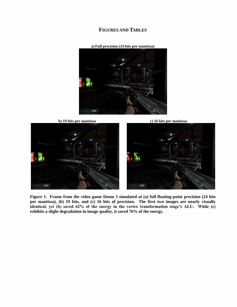
with graceful degradation of image quality. Figure 1 illustrates this key idea by showing rendered
frames from a popular video game at different precisions. Our prior analytical model suggested that
we could realize savings of around 35% [1] in the vertex shader‘s ALU, but our new work shows this
estimate was much too conservative. Our presented energy model, based on simulations of newly-
designed circuits, shows that savings of 58% and greater are possible, leading to an overall savings of
10% or more in a mobile GPU. This 10% is expected to increase as our approach enables new,
unexplored savings. The first is reduced-precision data traffic to the vertex shader, the precision of
which will be dictated by the precision of the vertex shader. The second straightforward application
is the arithmetic in the pixel shader, which consumes even more energy than the arithmetic in the
vertex shader, and its associated memory traffic. We expect substantial savings in both these areas.
In current graphics applications, a large amount of arithmetic is performed. For each frame (out of
the 30-60 frames per second), millions of triangles are transformed from 3D coordinate space into a
2D space. Each one of these triangles is then enumerated into a set of pixels on the screen; there may
be from tens to thousands of pixels per triangle. Each pixel is then, at a minimum, written to a frame
buffer memory, but it is usually also subject to another round of tens or hundreds of arithmetic
operations to compute per-pixel color and texture. In order to accomplish a feat of such magnitude,

separate hardware is utilized for all of this processing: the GPU. The main processing steps in a GPU
are shown in Figure 2.
Today‘s graphics hardware demands large amounts of power. Typical high-end desktop graphics
cards not only draw current from the motherboard, but also require multiple rails from a powerful
(650-850W) power supply [2]. It is largely for this reason that graphics applications in mobile
devices have been very limited and only able to handle modest polygon and pixel rates. Mobile
power supplies simply cannot supply the energy necessary for high performance graphics for an
extended period of time.
There is much demand, however, for greater graphics functionality in mobile devices. As mobile
users grow accustomed to having graphical capabilities, they will increasingly expect graphics
capabilities similar to those of desktop computers. By reducing the energy used in the GPU, we can
enable more advanced graphics in mobile devices and/or increase battery life. Moreover, energy-
efficient graphics also has a benefit for desktop computers: power consumption will decrease,
thereby reducing the power supply and cooling requirements.
In this work, we have focused on the vertex transformation stage of the graphics pipeline to
evaluate the feasibility of the concept of energy-precision tradeoffs. The transformation stage
converts vertex coordinates from user-defined floating-point representation to screen-space fixed
point numbers. This transformation involves translation, rotation, scaling and perspective projection
[3]. In addition, this stage computes the contributions of lights to the illumination at the vertices
(again a floating-point computation). We have chosen this stage because it is well-known and fairly
standard, so we know how to model its architecture for energy and error analysis. Therefore, our
strategy has been to focus on vertex shading in this work, so as to determine the feasibility of our
approach, and then to subsequently apply it to other stages which account for even higher power
consumption, such as pixel shaders and memories [4].

In order to develop an energy model for the GPU‘s arithmetic as a function of precision, we design
several variable-precision adder and multiplier circuits. We apply fine-grain power gating techniques
to turn off the voltage supplied to the lower significant bits of an integer‘s representation. Note that
these variable-precision circuits can potentially be of use outside of the graphics domain as well, such
as in low-power DSPs, sensor network nodes, and wireless communication [5]. Simulating our
designs yields their energy vs. precision characteristics, which we then use to find the energy
performance of the entire vertex transformation stage.
Our approach was successfully validated using a hardware simulator [6]. Several frames of real-
world applications (e.g., Doom 3, Quake 4) were rendered at varying precisions, and the image
quality and energy consumption were quantified. In the average case, 58% energy savings was
possible with little or no errors in resulting images. Further, with acceptable errors that would not
significantly affect application usage, even higher (73%) energy savings were obtained.
Our variable-precision hardware design technique is adaptable and scalable to the ranges of needed
precisions, which can vary widely from application to application. In addition, due to the choice of
power-gating rather than clock- or signal-gating, our designs suppress nearly all the leakage current
of the circuitry, which is becoming more and more significant as smaller processes are used. While
the power gating techniques we used have been explored in the past, they have never been applied in
this manner. Variable-precision arithmetic designs have been limited to coarse power gating or
signal/clock gating; we are not aware of any fine-grain power-gated variable arithmetic circuits.
These two approaches suffer from drawbacks our approach addresses, namely unfulfilled power
savings in intermediate precisions in coarse power gating and leakage power when only using signal
or clock gating.
The specific contributions of this work are as follows:

Design techniques for dynamically fine-grained precision control in arithmetic hardware,
Application of these techniques to integer arithmetic addition and multiplication units,
Simulation of the designed circuits to assess energy savings and acceptability of incurred
overheads, and an energy model for the vertex transformation stage, and
Detailed simulation results of real-world applications with the energy characteristics of our
new circuits to evaluate the tradeoff between energy and precision.
The remainder of this paper is organized as follows. Section 2 details the past work in variable-
precision arithmetic and low-power techniques. Section 3 presents our work in designing and
simulating variable-precision arithmetic hardware. We then apply these circuits‘ characteristics in
simulating the energy savings gained by reducing the precision in the vertex transformation stage of
the graphics pipeline in Section 4. Finally, Section 5 gives a conclusion and directions for future
work.
2 RELATED RESEARCH
2.1 Variable precision techniques
Varying the precision of computations has been explored in prior work. Hao and Varshney [7] have
given a thorough treatment of the sources of errors inherent in reduced precision rendering and the
number of bits of precision required for a desired output. Akeley and Su [8] have used an interval
arithmetic model to find the minimum triangle separation in eye space to ensure correct occlusion.
Chittamuru et al. [9] have suggested variable-wordlength texture-mapping.
Outside of graphics, Alalusi and Victor [10] have shown how a coarse-grained approach to
reducing precision in hardware can be applied to integer applications. Tong et al. [11] and Jain [12]
have reported similar findings for floating-point applications. Software techniques for reducing the
bit-width, and therefore power consumption, of a multiplier have been proposed, such as by Han et

al. [13].
Varying the quality of results in favor of faster or more reliable operation has also been examined,
from Lafruit et al.‘s [14] work on graceful degradation of 3D algorithms, to Yasuura et al.‘s [15]
treatment of energy-performance tradeoffs in computational systems, to Yeh et al.‘s [16][17]
exploration of error tolerance in physics-based animation. None of these approaches, however, has
systematically explored energy-precision tradeoffs in a graphics pipeline.
2.2 Circuit designs for low power
We chose a simple power-gating method, though more complex methods do exist. For instance, if
there is a need to save the current state and data stored within a circuit while it is power-gated, Liao et
al. [18] and Kim et al. [19] have both proposed structures allowing for this capability. However, this
is far beyond what is needed in our approach to variable-precision arithmetic; there is no need for us
to store intermediate results in the lower, power-gated bits. So, we chose simpler techniques with
lesser overheads that can be applied to each bit of an arithmetic circuit, rather than the circuit as a
whole.
There has also been research directed towards low power arithmetic circuit design. Liu and Furber
[20] presented a low power multiplier, while Callaway and Schwartzlander [21] detailed the
relationship between power and operand size in CMOS multipliers. Tong et al. [11] suggested a
digit-serial multiplier design with three discrete bit-widths, resulting in a linear power savings. Lee et
al. [22] proposed a variable-precision constant multiplier that uses shifting in the place of
multiplication by powers of 2, realizing an energy savings of between 16% and 56%. Most similar to
our work is that of Huang and Ercegovac, who developed two-dimensional signal gating for variable
bit-width multipliers [23][24][25], realizing up to 66% power savings over a baseline implementation.
Phatak et al. [26] presented a low power adder and included a treatment of the adder‘s power usage

dependent on the number of significant bits. Kwong filed a patent for a variable-precision digital
differential adder for use in graphics rendering, but has not reported any power results [27]. Park et
al. have proposed a scheme in which energy can be traded for quality, similar to prior work [1], in a
DCT algorithm using only three ―tradeoff levels‖ [28]. Other research by Usami et al. [29] and
Sjalander et al. [30] has led to variable-precision power-gated multipliers, which will save leakage
current in smaller processes. However, both of these papers only allow for two different operating
precisions, while our approach provides a full range of possible precisions, adaptable to the intended
circuit application.
None of these approaches have the same design characteristics we used. First, our targeted
applications need very fine-grained control over the operating precision; thus, coarse-grained designs
which allow for, for example, 8, 16, or 24 bits simply do not offer the necessary degree of control.
Second, we believe that our use of power-gating will offer significant returns when also considering
the savings in decreased leakage current. To our knowledge, we are the first to propose designs with
both these features.
The VFloat library is meant to address some of these same problems – application-specific
precisions, reduced leakage current – but has only been implemented for FPGAs [31]. So, these
problems are only solved by actually reprogramming the hardware, which is not possible at runtime.
Specialized hardware for other domains has also been developed to reduce leakage current by
power gating the arithmetic hardware in certain ways, such as Ngo and Asari‘s [32] video processing
convolution hardware. There are key differences between our approaches, though; the convolution of
image data lets Ngo and Asari use a priori knowledge, such as the magnitude of common filter
coefficients, that we cannot count on in our design for certain optimizations, such as one and zero
detection. Also, they can count on the dynamic range of neighboring pixels to be relatively small,
leading to optimizations taking advantage of transforming this spatial coherence to temporal

coherence from the ALU‘s point of view. However, in a massively parallel GPU, it is highly unlikely
that neighboring pixels will be processed on the same ALU, rendering this approach infeasible for
our designs.
There are other low-power techniques as well, such as dynamic voltage scaling [33] and coarse-
grained power gating [34], which could be used for energy-efficient graphics. These techniques are
orthogonal to our work.
3 HARDWARE IMPLEMENTATION OF FINE-GRAINED DYNAMIC PRECISION CONTROL
Given the promising results of our error simulations of variable-precision arithmetic in mobile GPUs
[1] and the applicability of variable-precision hardware to other domains [5][10][13][16][17][28][31],
we then took to designing hardware that delivers the modeled variable-precision energy savings. We
chose three common integer adder designs to modify and looked into different ways to adapt a
standard array multiplier for variable-precision operation. The adders we used were a ripple-carry
adder, a uniform carry-select adder, and a Brent-Kung adder [35], each with their own strengths and
weaknesses. The ripple-carry adder is a simple design that uses very little hardware, but has the
longest critical path and therefore the longest propagation delay. The carry-select adder is faster but,
depending on the implementation, can use nearly twice as much area. The Brent-Kung adder,
although it has the highest area requirements, is the fastest of the three and is easily pipelined, making
it a popular and commonly-used design.
Any single component subject to power gating underwent three key modifications. First, the
arithmetic logic transistors were supplied with either a virtual power (header switch) or ground
(footer switch) signal controlled by sleep transistors driven by an enable signal, rather than actual
power or ground rails. This modification allows the power to the element to be cut off, thereby
practically eliminating the dynamic power consumption, and also potentially reducing leakage power

loss through the circuit. When deciding whether to use either a header or footer switch, we consider
the power and timing implications of each [36], as well as the desired output in the disabled state. In
the second modification, the outputs were either pulled down (for a header) or pulled up (for a footer
switch), depending on the larger context of the element, so that any downstream hardware will see a
consistent signal. This both reduces downstream switching and allows for transparent integration
with existing hardware; no special treatment of floating signals needs to be considered because the
outputs of disabled gates are not floating. Since the state of the output does not need to be preserved
when disabled, no extra registers are necessary. Lastly, the logic and gating transistors in the circuit
were resized in order to minimize the power or timing overheads of the modified designs
[33][36][37]. Figure 3 shows these changes applied to a standard full adder.
Fine-grained power gating, such as we propose, is subject to problems with ground bounce if large
portions of the circuit are switched at one time. Rush-current suppression can be implemented by
skewing the switching of portions of the circuit [38]. For our design, we can skew the switching by
disallowing very large changes in precision at one time. A possible approach is to have the software
driver monitor precision changes and sequence overly large ones as a series of smaller changes.
The operating precision is chosen by setting enable lines to each gated unit. Several approaches are
available for correctly setting enable signals. The most straightforward is to drive each gated element
based on a symbolic constant in a register. Alternatively, any manner of decoding circuitry can be
used to translate a shorter enable code bundled with operands into individual enable/disable signals.
The specific technique used will depend heavily on the application and the usage patterns of the unit.
It is highly likely, however, that whatever area overheads are incurred by the control circuitry will be
shared over several functional units, over an entire ALU, or even over multiple ALUs.

3.1 Modified adder designs
Differences in each of the three adders targeted led to distinct approaches to power gating for each.
We chose to explore designs of 24 bit integer adders, which are used in single-precision floating point
addition, a common operation in many applications. Past research [5][9][1] has shown that for some
target applications, the most readily available savings appear in the first twelve least significant bits
of a 24-bit adder, where reduced precision will not have an overly negative impact on application
utility. We limit the precision control of our proposed designs to the least significant sixteen bits.
We note here that though two of the adder designs we explore are rudimentary and not often used in
high-performance systems, we show later that they can be more energy-efficient than faster designs.
Furthermore, their relatively high latency does not render them useless in a GPU; performance in a
GPU is a function of throughput, which can be achieved by many pipelined ALUs with any given
latency (within reason).
3.1.1 Ripple-carry adder
We first chose to modify a ripple-carry adder. This is a very basic adder whose functionality is
immediately discernible, and it will serve as a baseline implementation. A ripple-carry adder simply
uses one full adder per bit of precision needed by the operands. In order to apply our technique, we
modify each full adder as described previously and shown in Figure 3. Disabling each successive full
adder has the effect of reducing the precision by a single bit. The modified design is shown in Figure
4.
3.1.2 Carry-select adder
Carry-select adders are slightly more complicated than a simple ripple-carry adder. They employ
several banks of smaller ripple-carry adders to make up one full-width adder, each computing two
carry paths in parallel. When the carry out signal from one block enters the next, multiplexers select
the correct carry path to output to the next stage, and so on. The first ripple-carry block does not
have the second carry path, since its carry-in signal is always ‗0.‘ It is treated like the modified
ripple-carry adder above. The other type of block is made up of two ripple-carry chains in parallel.
Applying our technique to these blocks involved gating each parallel pair of full adders as one unit,
leading to less power and area overhead than simply using the single full adder approach.
Specifically, our tested design was a uniform carry-select adder which uses four blocks of six full
adders, with all but the least significant block performing addition in parallel chains. Figure 5 shows
the details of a carry-select block with two layers of full adders gated as a single unit.
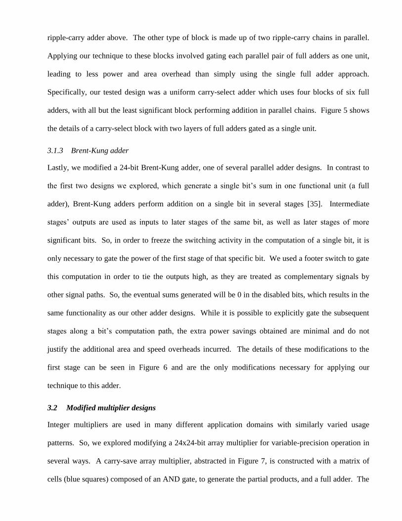
3.1.3 Brent-Kung adder
Lastly, we modified a 24-bit Brent-Kung adder, one of several parallel adder designs. In contrast to
the first two designs we explored, which generate a single bit‘s sum in one functional unit (a full
adder), Brent-Kung adders perform addition on a single bit in several stages [35]. Intermediate
stages‘ outputs are used as inputs to later stages of the same bit, as well as later stages of more
significant bits. So, in order to freeze the switching activity in the computation of a single bit, it is
only necessary to gate the power of the first stage of that specific bit. We used a footer switch to gate
this computation in order to tie the outputs high, as they are treated as complementary signals by
other signal paths. So, the eventual sums generated will be 0 in the disabled bits, which results in the
same functionality as our other adder designs. While it is possible to explicitly gate the subsequent
stages along a bit‘s computation path, the extra power savings obtained are minimal and do not
justify the additional area and speed overheads incurred. The details of these modifications to the
first stage can be seen in Figure 6 and are the only modifications necessary for applying our
technique to this adder.
3.2 Modified multiplier designs
Integer multipliers are used in many different application domains with similarly varied usage
patterns. So, we explored modifying a 24x24-bit array multiplier for variable-precision operation in
several ways. A carry-save array multiplier, abstracted in Figure 7, is constructed with a matrix of
cells (blue squares) composed of an AND gate, to generate the partial products, and a full adder. The
final summation step (dark blue rectangle) of our design was performed with a ripple-carry adder, for
simplicity. This adder was not variable precision, in order to fully separate the two designs, though it
would certainly make sense to combine our designs in practice. An n x n multiplier produces 2*n
product bits, but, in the larger context of a floating-point multiplier, only the high n bits (green
squares) are used, while the low n bits (red squares) are ignored.
The full adder of each of these cells is gated in a fashion similar to that shown in Figure 3, but we
also designed versions that have separate gating controls for the signals that propagate downwards
and those that propagate to higher bits. First, we tested simply suppressing the low-order bits in the
operands. Next, we gated the power to just one operand‘s lower bits, and then the lower bits of both
operands. Finally, we adapted a truncation multiplier with correction constant and extended the
column truncation to provide variable-precision operation with power gating. Each of the
accompanying illustrations represents the gating applied to an 8x8 adder operating at five bits of
precision.
3.2.1 Operand bit suppression
Suppressing the data entering the arithmetic units can be done in different ways. In our tests, we
assumed bit suppression at the source registers or before; we do not include specialized circuitry for
this purpose. Our results, then, will simply show the dynamic power saved. Since there is no power
gating performed, the leakage power will not be reduced.
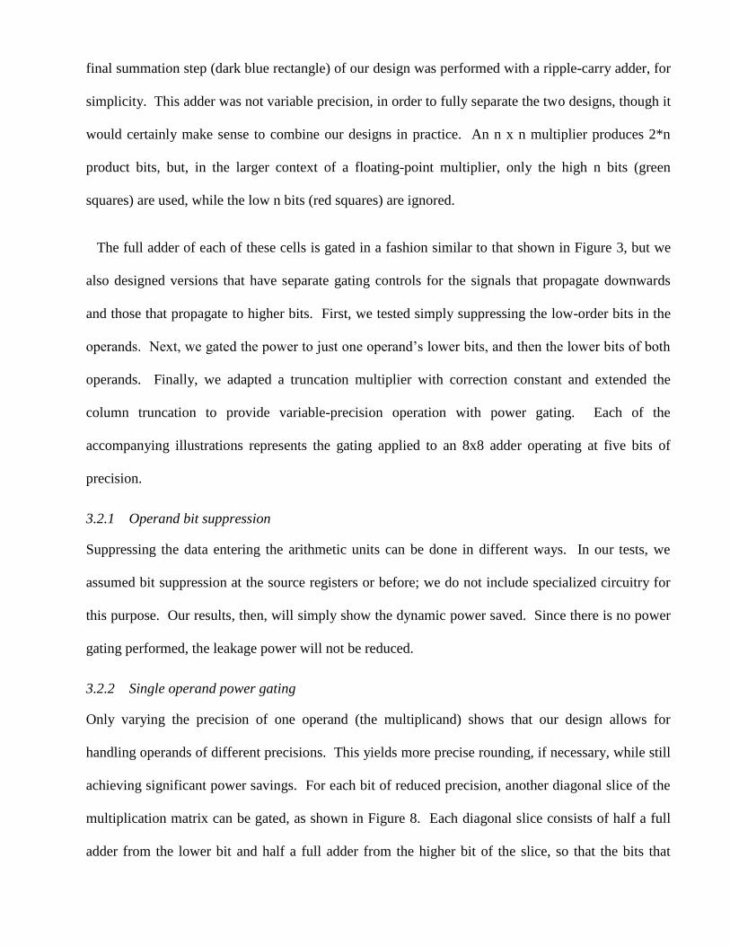
3.2.2 Single operand power gating
Only varying the precision of one operand (the multiplicand) shows that our design allows for
handling operands of different precisions. This yields more precise rounding, if necessary, while still
achieving significant power savings. For each bit of reduced precision, another diagonal slice of the
multiplication matrix can be gated, as shown in Figure 8. Each diagonal slice consists of half a full
adder from the lower bit and half a full adder from the higher bit of the slice, so that the bits that

would propagate further left are not affected. This mode will also have the lower bound for energy
savings in handling operands of different precisions (one operand at full precision).
3.2.3 Double operand power gating
By gating the low-order bits of both operands, even more circuitry is shut down with each bit of
reduced precision. As in part 2, a diagonal slice of the partial product matrix is gated for each bit of
the multiplicand, while an entire row is gated for each reduced bit of the multiplier. This gating
scheme is shown in Figure 9.
3.2.4 Column truncation
A truncation multiplier saves area and power by simply not implementing low-order columns of the
partial product generation stage. A correction constant which reasonably handles the average case is
added to the carry-in stage of the existing circuitry to correct for the incurred error, but errors can still
be large when the generated partial products in a column would all be 0 or 1. We extended the idea
of a truncation multiplier [39][40] by applying power gating to entire columns in order to reduce the
operating precision (Figure 10). As more columns are gated, the correction constant (supplied in a
similar manner to the precision selection) is changed by software to minimize the average error.
3.3 Simulation setup
We used LTSpice IV [41], built on the well-known Spice III [42] simulator, to simulate the netlists
generated by Electric for power and timing figures for a .13µm TSMC library with a Vdd of 1.3V,
frequency of 100MHz, and load capacitances of 0.01pF. First, we tested a smaller 8-bit version of
each adder exhaustively for correctness, and then we compared the results of adding 200 random
operands to a baseline 24-bit ripple-carry adder and visually compared the results to the waveforms
produced by the operations in software. We repeated these steps for the multipliers. In this way, we
verified the functionality of our designs. The same set of random 24-bit operands was used for the
power usage simulations of each modified unit at each operating precision. The current drain through

the supply voltage source was measured to determine the power consumed and energy used over
these operations. Next, a set of worst-case operands was used to find the longest propagation delay
of each adder, measured from the 50% level of the input‘s voltage swing to the 50% level of the
slowest output‘s voltage swing. Leakage power was found by first performing an operation on
random 24-bit operands to approximate the average case current draw. Then, power was measured
500ms after the operation to allow for the dynamic current draw to fade away, leaving only quiescent
current. We also devised an experiment to time the worst case delay in enabling/disabling all 16
controllable bits at a time. This will be, in effect, the timing penalty incurred for dynamically
changing precisions.
3.4 Circuit design results
We now present the power savings and area timing overheads of our designed circuits from
simulation. These results are from simulations of pre-layout circuit designs with realistic load
capacitances and transistor-sizing. While a more detailed, post-layout simulation would also include
the effects of wire capacitances, the results presented are strong indicators of the trends of energy
savings realizable as arithmetic precision is reduced. Area and timing overheads are difficult to
classify as either acceptable or unacceptable [37], so we compare our overheads with those in other
techniques. Finally, we compare our power savings with other approaches.
3.4.1 Power savings
The overall energy consumption for our adder designs as a function of precision is shown in Figure
11. To demonstrate that our design helps suppress leakage power, which is likely to become
increasingly significant as transistor technologies continue to shrink [43], Figure 12 shows the
leakage power for each adder circuit as a function of the operating precision. Similar graphs are
shown for the results of the modified multiplier power savings in Figure 13 and Figure 14. For
reference, single full-precision ripple-carry, carry-select, and Brent-Kung additions require 3.7, 7.1,
and 8.2 pJ, respectively, and a single full-precision multiplication requires 196.1 pJ.

The desired linear power savings are very apparent and significant in our proposed adder designs.
When using a Brent-Kung adder, for example, reducing the precision by just four bits will cause each
operation to use roughly 80% of the energy used by full precision operations. In many applications,
the precision can often be reduced by more than just four bits without sacrificing fidelity. For
example, in our graphics simulations [1], it has been shown that up to 12 bits can be lost without
causing the application to become unusable. This would give energy savings of close to 50% for
additions. Savings of this nature are expected, and are used to justify the use of variable-precision
arithmetic in some applications [9]. Also, though there was a slight energy overhead in the Brent-
Kung adder, this was made back after reducing the precision by only a single bit.
The ripple-carry and carry-select adders do not have any power overheads. This is due to the extra
series resistance added by the gating PMOS transistors causing the short-circuit currents to be
reduced. These lower currents do incur modest delay penalties, however, further discussed in Section
3.4.3.
There are some expected characteristics of the power/operation vs. precision trends worth noting.
Firstly, the ripple-carry adder has an almost perfectly linear slope. This is exactly what was predicted
in the first stage of our work, since precisely one full adder per bit is gated. Second, the carry-select
adder has two different regions of savings, due to the structure of the design. The first is seen in
precisions 24 through 18, which corresponds to the single layer of full adders being gated in
succession. After bit 18, at a precision of 17 and below, the savings are more aggressive as two full
adders per bit are gated and consume minimal power.
Leakage power consumption (Figure 12) shows analogous trends, as well. Firstly, all the adders
show linear savings, as expected. Also, the carry-select adder displays the same dual-slope that was
seen in the total power results. Furthermore, while there are some overheads, due to the added
transistors, they are overcome with a reduction in precision by only 4-6 bits.

The power savings for the multiplier designs, Figure 13, are even more promising than those of the
adders, due to the quadratic hardware complexity of the multipliers.
Just as the adders displayed interesting behavior, the multipliers show trends that warrant remark.
The design with the lowest power savings is that with only one gated operand (―X Gating‖), which
naturally results in linear power savings. Simple operand suppression is more useful, but, as noted
previously, does not stop leakage current (see Figure 14), which will be more of a problem when
using a smaller technology. Gating both operands (―XY Gating‖) performs better than suppression
with a similar inverse quadratic decay, expected from the gating pattern. Using this approach, one
must only reduce the precision by 5 bits in order to see a 50% decrease in power consumption.
Column gating exhibited even more dramatic power savings, which is to be expected, as roughly half
of the multiplier was disabled (or not implemented) from the start. However, it must be noted that
the precision is not guaranteed to be exactly the number specified, since the correction constant does
not change with operands, only with precision. Errors of one to a few low-order bits must be
acceptable when using this scheme, which limits its utility somewhat but gives it the greatest power
savings.
The leakage power vs. precision curves, in Figure 14, resemble those of the full power vs. precision
curves of Figure 13. While operand suppression does not reduce leakage power, as was expected, the
other designs save significant power, and overcome very small power overheads after only one bit of
reduced precision. So, the power savings will be immediately realized.
3.4.2 Area overheads
The extra area incurred by the gating and control circuitry must not overshadow the power savings
they enable. Table I shows the overheads, as extra transistor area, for each adder type, and Table II
shows the same figures for our multiplier‘s designs. We have not included the area penalty for
precision control circuitry, as it is dependent on the implementation chosen. Also, any overhead of
the control circuitry would likely be shared among several units; the amortized impact on a single
unit, such as an adder, would likely be acceptably small.
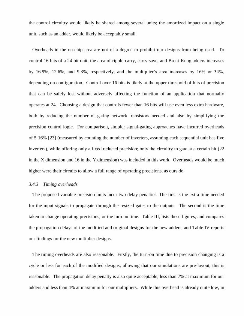
Overheads in the on-chip area are not of a degree to prohibit our designs from being used. To
control 16 bits of a 24 bit unit, the area of ripple-carry, carry-save, and Brent-Kung adders increases
by 16.9%, 12.6%, and 9.3%, respectively, and the multiplier‘s area increases by 16% or 34%,
depending on configuration. Control over 16 bits is likely at the upper threshold of bits of precision
that can be safely lost without adversely affecting the function of an application that normally
operates at 24. Choosing a design that controls fewer than 16 bits will use even less extra hardware,
both by reducing the number of gating network transistors needed and also by simplifying the
precision control logic. For comparison, simpler signal-gating approaches have incurred overheads
of 5-16% [23] (measured by counting the number of inverters, assuming each sequential unit has five
inverters), while offering only a fixed reduced precision; only the circuitry to gate at a certain bit (22
in the X dimension and 16 in the Y dimension) was included in this work. Overheads would be much
higher were their circuits to allow a full range of operating precisions, as ours do.
3.4.3 Timing overheads
The proposed variable-precision units incur two delay penalties. The first is the extra time needed
for the input signals to propagate through the resized gates to the outputs. The second is the time
taken to change operating precisions, or the turn on time. Table III, lists these figures, and compares
the propagation delays of the modified and original designs for the new adders, and Table IV reports
our findings for the new multiplier designs.
The timing overheads are also reasonable. Firstly, the turn-on time due to precision changing is a
cycle or less for each of the modified designs; allowing that our simulations are pre-layout, this is
reasonable. The propagation delay penalty is also quite acceptable, less than 7% at maximum for our
adders and less than 4% at maximum for our multipliers. While this overhead is already quite low, in
low-power devices, a high clock speed is usually not the primary concern. In fact, the clock may be
dynamically slowed to take advantage of lighter workloads. Our techniques are orthogonal to
frequency scaling; both can be used on the same circuitry to gain energy savings. As before, our
designs are competitive compared with a signal-gated approach that shows delay overheads of 7-11%
[23].
3.4.4 Comparison with other techniques
Here, we compare the energy savings of our proposed circuits with the savings of other variable-
precision techniques. This is a difficult task, as other reported findings differ in technology sizes and
other factors. We offer comparisons of our approach vs. both coarse-grain power gating and signal
gating.
We first look at one representative coarse-grain power gating technique, a twin-precision multiplier
[30], which is nearly directly comparable with our results, thanks to the same size process (130nm)
and similar driving voltages (our 1.3V vs. their 1.2V). There are several differences between our two
approaches: Sjalander et al.‘s circuit is based on a tree multiplier, while ours is a simpler array
multiplier; their approach allows for only two different precisions to be used, whereas our design
offers a continuum of operating precisions. While they do not report all the necessary results, such as
power consumption of the multiplier in 16 bit mode, one metric that we can compare is the power
consumption of a standard 16 bit multiplier operating on 8 bit operands compared to their twin-
precision cutoff multiplier operating on 8 bit operands. The ratio between these two is 3.2, whereas
the ratio between our multiplier operating at full and half precisions is 6.8, indicating that we see
more savings for the same reduction of precision. However, this comparison is unfair, as we do not
implement power gating below 8 bits. So, if we treat 8 bits as ―0‖ and find the ratio between the new
full and half precisions (24 and 16, respectively), we arrive at a ratio of 3.4. This is slightly better
than the twin-precision multiplier. Lastly, even though our unpipelined multiplier has a delay 4 to 5
times that of Sjalander et al.‘s, depending on configuration and despite our 50% larger bit width, our
design is more flexible and has an energy efficiency 1.7 higher than their design.
We now compare our results against a signal-gated approach by Huang and Ercegovac [23]. In this
compared work, a 32 bit multiplier is signal-gated in both the X and Y dimensions, and is the
technique on which we have based our ―XY‖ power gating approach. However, they hardwire gating
lines at the 22nd
bit of one dimension and the 16th
bit of the other. We have only reported results for
symmetric power gating, though we could drive ours with two different precisions. So, to choose a
comparison, we first observe that they report results when gating, on average, 40% of each operand.
This equates, in our design, to an operating precision of 14.4. So, we will compare their reported
results with our results linearly interpolated between 14 and 15 bits. They report energy savings of
67% when using their most low-power design, and we show savings of 76% for our analogous XY
gating technique (column gating would yield better savings, but incurs computational errors not seen
in their approach). As expected, our own ―Suppression‖ technique, which mimics their coarse-grain
signal gating approach, has a power savings of 69%, which agrees closely with their results.
4 GPU ENERGY MODEL AND SIMULATION
Having designed variable-precision arithmetic circuits with promising energy characteristics, we
adapt our earlier work in reduced-precision rendering [1] to incorporate these new results to prove
their utility. We build an energy model of the vertex transformation stage of a GPU and then use a
graphics hardware simulator to provide the necessary workload information to our model.
4.1 Energy Model
In this section, we present the energy model we use for estimating the energy spent in rendering a
frame. We justify our use of the characteristics of the newly-designed circuits detailed above as the
models for addition and multiplication. We then use the energies for these operations to extend the
model to more complex operations. The energy spent in a dot product, for example, is the sum of the

energies of its constituent additions and multiplications, and likewise for multiply-add and min/max
operations. We also show the model used for reciprocal and reciprocal square root operations. We
assume that these composite operations are performed sequentially, with the intermediate results
stored in registers, just like the final results from an addition or multiplication.
4.1.1 Addition
Floating-point additions are computationally expensive operations consisting of several steps. First,
the operands‘ exponents must be made equal, which requires shifting a mantissa. Then, mantissas are
added. Another normalization step is needed to align the sum‘s mantissa, followed by a configurable
rounding step.
We focus on only the addition of mantissas when modeling the floating-point energy. The energy
in rounding is significant [12] in a traditional FPU, but when doing reduced precision calculations,
we assume a simple round toward zero (truncation) scheme which does not need any intricate
rounding support. This is common in graphics hardware [11]. Shifting, too, is significant, but of a
lesser magnitude than the addition itself once a simple shifter that need not perform any necessary
rounding operations is implemented [44]. Furthermore, the energy in shifting will scale linearly with
the bitwidth of the operands, just like the addition itself. So, the energy spent in a reduced-precision
floating point adder will consist of the integer addition (such as our Brent-Kung design) and the
shifter energy, both of which will scale with precision. So, we model the energy used by a floating
point adder as the energy of an integer adder with the understanding that our estimated energy will be
less than the real energy by an amount that will decrease along with the operating precision. We use
the results of our new Brent-Kung adder design as our energy model for addition, EAdd, as a function
of precision p:
(1)

4.1.2 Multiplication
Multiplication is modeled as integer multiplication at a given precision. Tong et al. [11] found that
81.2% of the energy consumed in floating point multiplication is spent in the mantissa multiplication
or over 98% when the rounding unit is disregarded, which is the case for simple truncation.
Therefore, we focus on the mantissa multiplication, and use the results of a standard array multiplier,
modified for variable-precision operation with XY operand gating, as presented in Section 3.2.3 as
our energy model for multiplication:
(2)
4.1.3 Reciprocal/reciprocal square root
Historically, several types of iterative reciprocal and reciprocal square root calculations have been
used in hardware. SRT division converges upon the correct result linearly, while Newton-Raphson
(and others based on Newton‘s method) [45] and Goldschmidt (and other power series expansions
[46]) converge quadratically to the result.
In order to make use of our variable-precision designs, we chose to model reciprocal and reciprocal
square root computations with narrow bit-width multiplications introduced by Ercegovac et al. [39],
based on Taylor series expansion. This method consists of a reduction step, evaluation step, and
post-processing. Several iterations of the evaluation step are needed, for which some operations
require only p/4 bits of precision. (For our circuits, low precision is bounded at 8, so this term is
constant, though it could be variable if the application called for such low precisions that control of
the lower bits was implemented.) When the energies for all stages are summed, the total
consumptions are as follows for a reciprocal (3) and a reciprocal square root (4) operation:
(3)
(4)
4.2 Variable-precision GPU simulation results
In order to utilize our energy model and visualize the actual errors in rendering, we incorporate the
model into ATTILA, a cycle-accurate GPU simulator [6]. ATTILA accepts graphics traces captured
from a live application and, by default, outputs images and statistics of interest to GPU architects
(cache efficiency, etc.). We added energy logging functionality: when an operation is executed, it
calculates its own energy usage based on the current precision (kept constant during a given
simulation) and logs this information for further analysis. In addition, the simulator was modified to
provide full support for variable-precision vertex transformations. The GPU‘s arithmetic functions
were modified to operate on a custom data type that performs truncation of floating-point results to
any specified precision. For each simulated frame, the transformed vertices and resulting color buffer
are also saved, which allows for examination of error caused by reducing transformation precision.
Thus, the data gathered from the simulator is the energy usage of each operation per cycle, the final
frame buffer for the simulated frames, and the positions of transformed vertices.
The applications that we simulated and analyzed were Doom 3, Prey, Quake 4, and a simple torus
viewer, all traces released by the ATTILA group specifically for use with the simulator and seen in
Figure 15. Several hundred frames (to create useful videos) of the first two applications were
simulated, and several sample frames, used for energy and error analysis, were logged for all four
applications. The sample frames for the three games were chosen randomly, and each included a
large amount of texture-mapped and lit 3D geometry as well as 2D user interface components. Only
a single frame was traced for the simple torus viewer. We simulated these applications at a resolution
of 640 x 480 pixels, which is a higher resolution than all but the newest mobile devices. We also see
that relative error is independent of screen size, so the visual errors will not be any more noticeable at
higher resolutions; our approach will still apply to a range of devices.

4.2.1 Energy savings
The energy characteristics of the applications were as generally expected, given our energy model:
the energy usage was higher at higher precisions, and decayed quadratically (due to the multiplication
unit‘s savings) towards lower precisions. The energy savings compared to the unmodified circuitry
(far-right data point of each curve ―Full‖) is significant, even for the variable-precision circuitry
running at full precision (―24‖), due to the ability to perform intermediate computations of RCP/RSQ
operations with less precision. Full-precision hardware does not have this immediate savings.
Furthermore, work involved in transforming vertices is not dependent on screen size, so the results
were identical for the same frame of a given application at different sizes. Figure 16 shows the graph
of simulated power vs. precision.
4.2.2 Energy-precision tradeoff
In prior work, we analyzed the errors incurred by reducing the precision of the vertex
transformation stage [1]. This metric of error is defined as the screen-space Euclidean distance
between the transformed full-precision and reduced-precision vertex. Using this analysis with our
new energy results, we can now see how much energy could be saved by using the circuits in real
applications. Figure 17 shows the energy-precision tradeoff curves for all simulated applications.
Energy usage is normalized with respect to the unmodified hardware designs for each application so
savings are readily apparent as a percentage of the total energy consumed. We have seen that xy
errors did not cause any perceptible errors when these errors were less than a tenth of a pixel on
average. Furthermore, applications did not become unusable until the errors in x and y exceeded, on
average, a pixel. At these errors, energy saved was roughly 75% and 85%, respectively. However,
actual savings were not quite this pronounced, since z-fighting limited the utility of the applications
before xy errors grew to an unacceptable level [1].

5 CONCLUSIONS AND FUTURE WORK
We have applied power-gating techniques to several standard adders and an array multiplier,
converting them to be dynamic, fine-grained variable-precision circuits. Our designs show
significant savings when reducing the precision of integer adders and multipliers in order to save
dynamic and static power consumption. We have shown that the overheads caused by this power
gating are modest, and that the precision only needs to be reduced by one or two bits in order to start
seeing the rewards of power savings.
We then used the energy characteristics of the proposed circuits to build an energy model of the
vertex transformation stage of a GPU. When we reduce the precision of the arithmetic to a level
which will not cause any visible errors, we can save roughly 58% of the energy in the ALU of this
stage. Furthermore, reducing the precision to a degree which causes only minor visual artifacts can
save, on average, 73% of the energy.
Our results show that significant energy savings can be achieved by using reduced-precision vertex
computation. Using an energy model [4], we have estimated the ALU operations in the vertex shader
to consume around 15-20% of the total energy in a mobile GPU for recent applications. In this
energy model, fetching vertices from main memory was properly accounted for in a separate
percentage, but this 15-20% does include control logic, data buffering, and texture fetching. We
argue that these costs, unaccounted for in our savings estimates, are small enough not to change our
results appreciably. In particular, control logic energy will be amortized over a large number of
ALUs running in lockstep on the GPU, unlike in a CPU which may execute different instructions per
ALU. Moreover, we expect to adapt local data buffering to become variable-precision as well, by
adapting advances in narrow-operand register file addressing [47][48], which will make its energy
scale with bitwidth. Finally, texture fetches in the vertex stage are not very common; modern
applications rely on per-pixel shading, including texturing, to achieve their sophisticated appearance.

Therefore, all of the energy terms have either been appropriately accounted for in our calculations or
they are small enough to be ignored.
While this work focuses only on the vertex stage, the energy-precision tradeoff proposed here
could likely be extended to other parts of the pipeline that also consume significant amounts of
energy, such as memory, texture units, rasterization, and the pixel shader . The pixel shader, another
candidate for variable-precision operation (half-precision operations are already supported),
consumes roughly 50% of the energy. We also believe that we can save energy in the memory
accesses, which currently constitute around 20% of the total energy, by reading and writing reduced-
precision data.
We will also extend our circuit designs into a full variable-precision ALU for use in many contexts.
This will necessitate designing other functional units, such as shifters and dividers. Next, we will
incorporate these circuits into a variable-precision floating-point unit, as there are demonstrated uses
for such a unit. With such variable-precision units available, we can explore new approaches to
variable-precision data storage and signaling. While we have presented several adder designs, we are
confident our approach will apply to other adders, as well, including carry-save adders, Kogge-Stone
and other parallel adders, and pipelined implementations. Likewise, we believe we can apply our
techniques to different multiplier designs, such as Wallace or Dadda trees. One of these currently
unexplored designs may prove to be most useful in constructing our eventual larger units.
REFERENCES
[1] J. Pool, A. Lastra, and M. Singh, ―Energy-precision tradeoffs in mobile graphics processing
units,‖ Proceedings of the IEEE International Conference on Computer Design, (2008), pp. 60-
67.
[2] AMD Corporation, ATI Radeon HD 5970 Graphics System Requirements, (2011),
http://www.amd.com/us/products/desktop/graphics/ati-radeon-hd-5000/hd-5970/Pages/ati-
radeon-hd-5970-overview.aspx#3 .
[3] J. D. Foley, A. vanDam, S. K. Feiner, and J. F. Hughes, Computer Graphics: Principles and
Practice in C, Addison-Wesley, 2nd
edition (1995).
[4] J. Pool, A. Lastra, and M. Singh, ―An energy model for graphics processing units,‖
Proceedings of the IEEE International Conference on Computer Design, (2010), pp. 409-416.
[5] S. Yoshizawa and Y. Miyanaga, ―Tunable wordlength architecture for low power wireless
FDM demodulator,‖ Proceedings of the IEEE International Symposium on Circuits and
Systems, (2006).
[6] V. Moya, C. Gonzalez, J. Roca, A. Fernandez, and R. Espasa, ―ATTILA: A cycle-level
execution-driven simulator for modern GPU architectures,‖ Proceedings of the IEEE
International Symposium on Performance Analysis of Systems and Software, (2006), pp. 231-
241.
[7] X. Hao and A. Varshney, ―Variable precision rendering,‖ Proceedings of the Symposium on
Interactive 3D Graphics, (2001), pp 149-158.

[8] K. Akeley and J. Su, ―Minimum triangle separation for correct Z-buffer occlusion,‖
Proceedings of the 21st ACM Symposium on Graphics Hardware, (2006), pp.27-30.
[9] J. Chittamuru, W. Burleson, and J. Euh, ―Dynamic wordlength variation for low-power 3D
graphics texture mapping,‖ IEEE Workshop on Signal Processing Systems, (2003), pp. 251.
[10] S. Alalusi and B. Victor, ―Variable word width computation for low power,‖ Presentation
Material in CS252: Computer Architecture, The University of California at Berkeley (2000).
Available: http://citeseerx.ist.psu.edu/viewdoc/summary?doi=10.1.1.125.7534.
[11] J.Y.F. Tong, D. Nagle, and R. Rutenbar, ―Reducing power by optimizing the necessary
precision/range of floating-point arithmetic,‖ IEEE Transactions on VLSI Systems (2000),
Vol. 8, N° 3, pp. 273-286.
[12] S. Jain, Low-power Single-precision IEEE Floating-point Unit, Master‘s Thesis at the
Massachusetts Institute of Technology (2003), pp. 26. Available:
http://groups.csail.mit.edu/cag/scale/papers/seltsame-meng.pdf.
[13] K. Han, B. L. Evans, and E.E. Swartzlander, Jr, ―Data wordlength reduction for low-power
signal processing software,‖ IEEE Workshop on Signal Processing Systems, (2004), pp. 343-
348.
[14] G. Lafruit, L. Nuchtegaele, K Denolj, and J. Bormuns, ―3D computational graceful
degradation,‖ Proceedings of the IEEE International Symposium on Circuits and Systems,
(2000), pp. 547-550.
[15] H. Yasuura, T. Ishihara, and M. Muroyama, ―Energy management techniques for SOC
design,‖ Chapter 6 in Essential Issues in SOC Design, Springer Netherlands, Youn-Long Steve
Lin, Editor (2006), pp. 177-223.

[16] T. Yeh, G. Reinman, S. Patel, and P. Faloutsos, ―Fool me twice: exploring and exploiting error
tolerance in physics-based animation,‖ ACM Transactions on Graphics (2007), pp. 5:1-5:11.
[17] T. Yeh, P. Faloutsos, M.D. Ercegovac, S. Patel, and G. Reinman, ―The art of deception:
adaptive precision reduction for area efficient physics acceleration,‖ 40th
Annual IEEE/ACM
International Symposium on Microarchitectures, (2007), pp. 394-406.
[18] S. Kim, S.V. Kosonocky, D.R. Knebel, and K. Stawiasz, ―Experimental measurement of a
novel power gating structure with intermediate power saving mode,‖ Proceedings of the
International Symposium on Low Power Electronics and Design, (2004), pp. 20-25.
[19] W. Liao, J.M. Basile, and L. He, ―Leakage power modeling and reduction with data retention,‖
IEEE/ACM International Conference on Computer Aided Design, (2002), pp. 714-719.
[20] Y. Liu and S. Furber, ―The design of a low power asynchronous multiplier,‖ International
Symposium on Low Power Electronics and Design, (2004), pp. 365-371.
[21] T. K. Callaway and E. E. Swartzlander Jr, ―Power-delay characteristics of CMOS multipliers,‖
Proceedings of the 13th
IEEE Symposium on Computer Arithmetic, (1997), pp. 26-32.
[22] Y. Lee, H., and K. Chung, ―Low power MAC design with variable precision support,‖ IEICE
Transactions on Fundamentals of Electronics, Communications and Computer Science (2008),
Vol. 92, N° 7, pp. 1623-1632.
[23] Z. Huang and M. Ercegovac, ―Two-dimensional signal gating for low-power array multiplier
design,‖ IEEE International Symposium on Circuits and Systems, (2002), pp. 489-492.

[24] Z. Huang and M. Ercegovac, ―Two-dimensional signal gating for low power in high-
performance multipliers,‖ Proceedings of the SPIE on Advanced Signal Processing
Algorithms, Architectures, and Implementations, (2003), pp. 499-509.
[25] Z. Huang and M. Ercegovac, ―High-performance low-power left-to-right array multiplier
design,‖ IEEE Transactions on Computers (2005), Vol. 54, N° 3, pp. 272-283.
[26] D. Phatak, S. Kahle, H. Kim, and J. Lue, ―Hybrid signed-digit representation for low power
arithmetic circuits,‖ Proceedings of the Lower Power Workshop in Conjunction with ISCA,
(1998).
[27] M. Kwong, ―Low power, variable precision DDA for 3D graphics applications,‖ United States
Patent no. 6947056, Sep. 20, (2005).
[28] J. Park, J. H. Choi, and K. Roy, ―Dynamic bit-width adaptation in DCT: an approach to trade
off image quality and computation energy,‖ IEEE Transactions on VLSI Systems (2010),
Vol.18, N° 5, pp.787-793.
[29] K. Usami, M. Nakata, T. Shirai, S. Takeda, N. Seki, H. Amano, and H. Nakamura,
―Implementation and evaluation of fine-grain run-time power gating for a multiplier,‖
Proceedings of the IEEE International Conference on IC Design and Technology, (2009), pp.
7-10.
[30] M. Sjalander, M. Drazdziulis, P. Larsson-Edefors, and H. Eriksson, ―A low-leakage twin-
precision multiplier using reconfigurable power gating,‖ IEEE International Symposium on
Circuits and Systems, (2005), pp. 1654-1657.
[31] X. Wang and M. Leeser, ―VFloat: A variable precision fixed- and floating-point library for
reconfigurable hardware,‖ ACM Transactions on Reconfigurable Technology and Systems
(2010), Vol. 3, N° 3, pp. 16:1-16:34.
[32] H. Ngo and V. Asari, ―Partitioning and gating technique for low-power multiplication in video
processing applications,‖ Microelectronics Journal (2009), Vol. 40, N° 11, pp. 1582-1589.
[33] J. Mao, Q. Zhao, and C. G. Cassandras, ―Optimal dynamic voltage scaling in power-limited
systems with real-time constraints,‖ 43rd
IEEE Conference on Decision and Control, (2004),
pp. 1472-1477.
[34] M. H. Chowdhury, J. Gjanci, and P. Khaled, ―Innovative power gating for leakage reduction,‖
IEEE International Symposium on Circuits and Systems, (2008), pp. 1568-1571.
[35] R. Brent and H. Kung, ―A regular layout for parallel adders,‖ IEEE Transactions On
Computers (1982), Vol. C-31, N° 3, pp. 260-264.
[36] K. Shi and D. Howard, ―Sleep transistor design and implementation – simple concepts yet
challenges to be optimum,‖ International Symposium on VLSI Design, Automation and
Testing, (2006), pp. 1-4.
[37] A. Sathanur, A. Calimera, A. Pullini, L. Benini, A. Macii, E. Macii, and M. Poncino, ―On
quantifying the figures of merit of power-gating for leakage power minimization in nanometer
CMOS circuits,‖ Proceedings of the IEEE International Symposium on Circuits and Systems,
(2008), pp. 2761-2764.
[38] K. Usami, T. Shirai, T. Hashida, H. Masuda, S. Takeda, M. Nakata, N. Seki, H. Amano, M.
Namiki, M. Imai, M. Kondo, and H. Nakamura, ―Design and implementation of fine-grain
power gating with ground bounce suppression,‖ 22nd
International Conference on VLSI
Design, (2009), pp.381-386.
[39] M. Ercegovac, T. Lang, J-M. Muller, and A. Tisserand, ―Reciprocation, square root, inverse
square root, and some elementary functions using small multipliers,‖ IEEE Transactions on
Computers (2000), Vol. 49, N° 7, pp. 628-637.
[40] E.G. Walters, III. and M. Schulte, ―Efficient function approximation using truncated
multipliers and squarers,‖ 17th
IEEE Symposium on Computer Architecture, (2005), pp. 232-
239.
[41] Linear Technology, LTSpice. Download: http://www.linear.com/designtools/software/#Spice.
[42] The University of California at Berkeley, Spice Simulator. Available:
http://bwrc.eecs.berkeley.edu/classes/icbook/spice/.
[43] K. Roy, S. Mukhopadhyay, and H. Mahmoodi-Meimand, ―Leakage current mechanisms and
leakage reduction techniques in deep-submicrometer CMOS circuits,‖ Proceedings of the
IEEE (2003), Vol. 91, N° 2, pp. 305-327.
[44] B.R. Sheikh and R. Manohar, ―An operand-optimized asynchronous IEEE 754 double-
precision floating-point adder,‖ IEEE Symposium on Asynchronous Circuits and Systems,
(2010), pp.151-162.
[45] D. Chen, B. Zhou, Z. Guo, and P. Nilsson, ―Design and implementation of reciprocal unit,‖
48th
Midwest Symposium on Circuits and Systems, (2005), pp.1318-1321.

[46] N. Foskett, R. Prevett, and S. Treichler, ―Method and system for performing pipelined
reciprocal and reciprocal square root operations,‖ United States Patent no. 7117238, NVIDIA
Corporation, October, (2006).
[47] S. Tallam and R. Gupta, ―Bitwidth aware global register allocation,‖ 30th
ACM Symposium on
Principles of Programming Languages, (2003), pp. 85-96.
[48] O. Ergin, D. Balkan, K. Ghose, and D. Ponomarev, ―Register packing: exploiting narrow-
width operands for reducing register file pressure,‖ 37th
Annual IEEE/ACM International
Symposium on Microarchitecture, (2004), pp. 304-315.
FIGURES AND TABLES
a) Full precision (24 bits per mantissa)
b) 19 bits per mantissa c) 16 bits per mantissa
Figure 1. Frame from the video game Doom 3 simulated at (a) full floating-point precision (24 bits
per mantissa), (b) 19 bits, and (c) 16 bits of precision. The first two images are nearly visually
identical, yet (b) saved 62% of the energy in the vertex transformation stage‟s ALU. While (c)
exhibits a slight degradation in image quality, it saved 76% of the energy.

Figure 2. The input and output of three stages of a typical graphics pipeline: the
vertex shader (performs the vertex transformation), rasterization (generates
pixels touched by a triangle), and the pixel shader (performs per-pixel
operations).
Figure 3. Power gating applied to a full adder. Depending on the value supplied
on the Enable line, the transistors in the gates either receive an actual Vdd or just
a floating input, which does not provide a path for current to follow. The
transistors connected to the outputs only pull the values low if the block is
disabled, providing components downstream from the adder with a constant
value.

Figure 4. A section of a modified ripple-carry adder. Each full adder has its own
"Enable" signal in order to gate the power used by the unit. It is assumed that if
Enable(n) is low, then Enable(i) is also low, for all i<n.
Figure 5. A portion of the double full adder chain of a carry-select adder block. Each
gated unit is two modified full adders, as in Figure 3, which share the same gating
transistor, saving area and timing penalties. The final sum is chosen with a
multiplexer, driven by the carry-in of the previous block.
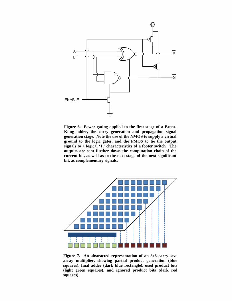
Figure 6. Power gating applied to the first stage of a Brent-
Kung adder, the carry generation and propagation signal
generation stage. Note the use of the NMOS to supply a virtual
ground to the logic gates, and the PMOS to tie the output
signals to a logical „1,‟ characteristics of a footer switch. The
outputs are sent further down the computation chain of the
current bit, as well as to the next stage of the next significant
bit, as complementary signals.
Figure 7. An abstracted representation of an 8x8 carry-save
array multiplier, showing partial product generation (blue
squares), final adder (dark blue rectangle), used product bits
(light green squares), and ignored product bits (dark red
squares).

Figure 8. When gating only one operand, the multiplicand,
diagonal slices of the partial product matrix are disabled. This
allows for more precise rounding, if required.
Figure 9. When gating both operands, entire rows of the
multiplier‟s partial product matrix are disabled in addition to
the diagonal slices of the multiplicand.

Figure 10. Column truncation extends the premise of a
truncation multiplier by applying power gating to entire
columns at a time. In addition, not every column is
implemented in hardware, saving significant circuit area.
Figure 11. Energy/operation vs. precision of the different adder designs. The ripple-carry
adder uses very little energy per operation, while the carry-select and Brent-Kung use
nearly double this amount. These others, though, are significantly faster.
0
1
2
3
4
5
6
7
8
9
Base 24 23 22 21 20 19 18 17 16 15 14 13 12 11 10 9 8
En
erg
y (
pJ)
/ O
per
ati
on
Precision (bits)
Adder Energy/Operation vs. Precision
Ripple-Carry
Carry-Select
Brent-Kung
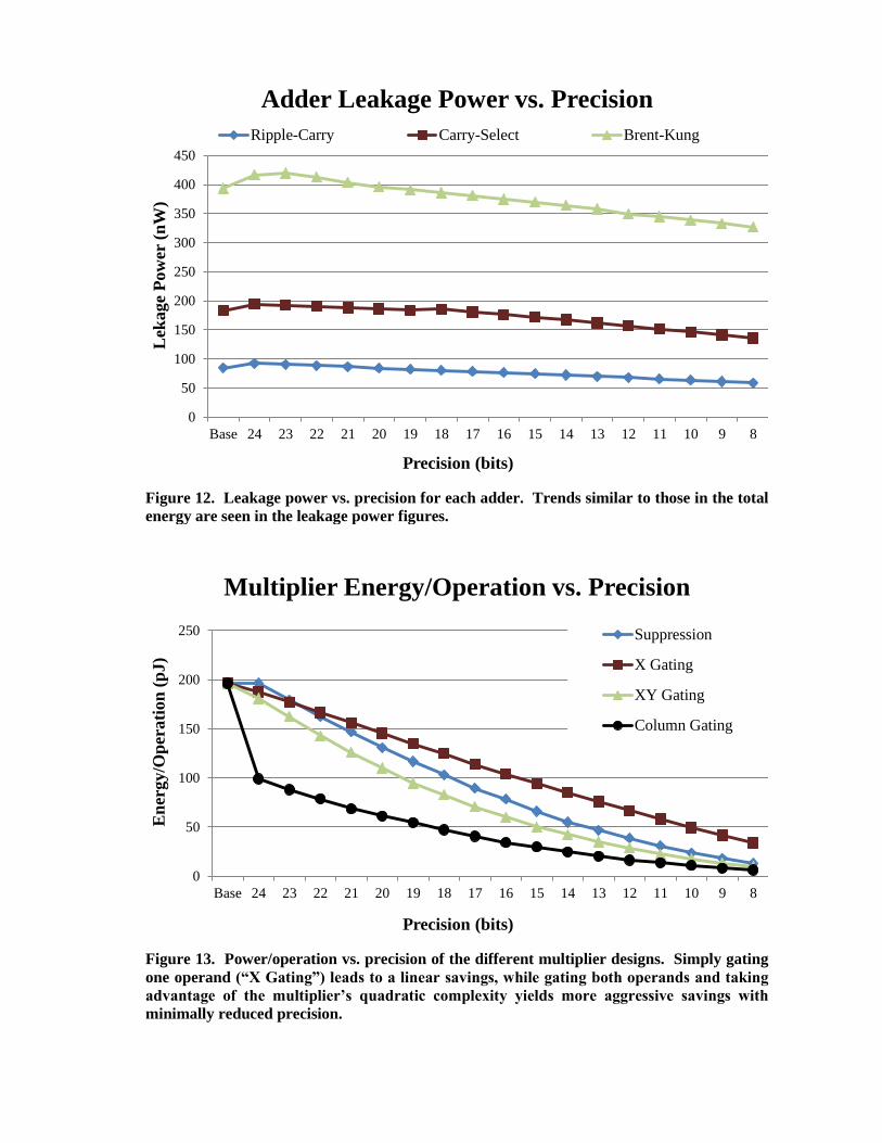
Figure 12. Leakage power vs. precision for each adder. Trends similar to those in the total
energy are seen in the leakage power figures.
Figure 13. Power/operation vs. precision of the different multiplier designs. Simply gating
one operand (“X Gating”) leads to a linear savings, while gating both operands and taking
advantage of the multiplier‟s quadratic complexity yields more aggressive savings with
minimally reduced precision.
0
50
100
150
200
250
300
350
400
450
Base 24 23 22 21 20 19 18 17 16 15 14 13 12 11 10 9 8
Lek
age
Pow
er (
nW
)
Precision (bits)
Adder Leakage Power vs. Precision
Ripple-Carry Carry-Select Brent-Kung
0
50
100
150
200
250
Base 24 23 22 21 20 19 18 17 16 15 14 13 12 11 10 9 8
En
ergy
/Op
erati
on
(p
J)
Precision (bits)
Multiplier Energy/Operation vs. Precision
Suppression
X Gating
XY Gating
Column Gating

Figure 14. Leakage power vs. precision of the different multiplier designs. Suppressing
operand data does not reduce leakage power at all, but the other curves show the same
trends observed in the full power savings.
TABLE I
EXTRA AREA NEEDED FOR MODIFIED ADDERS
Adder Type Transistor Area (μm
2)
Unmodified Modified Increase (%)
Ripple-Carry 4.606 5.383 16.9
Carry-Select 9.165 10.319 12.6
Brent-Kung 13.487 14.735 9.3
0
0.5
1
1.5
2
2.5
3
Base 24 23 22 21 20 19 18 17 16 15 14 13 12 11 10 9 8
Lea
kage
Pow
er (
uW
)
Precision (bits)
Multiplier Leakage Power vs. Precision
Suppression
X Gating
XY Gating
Column Gating
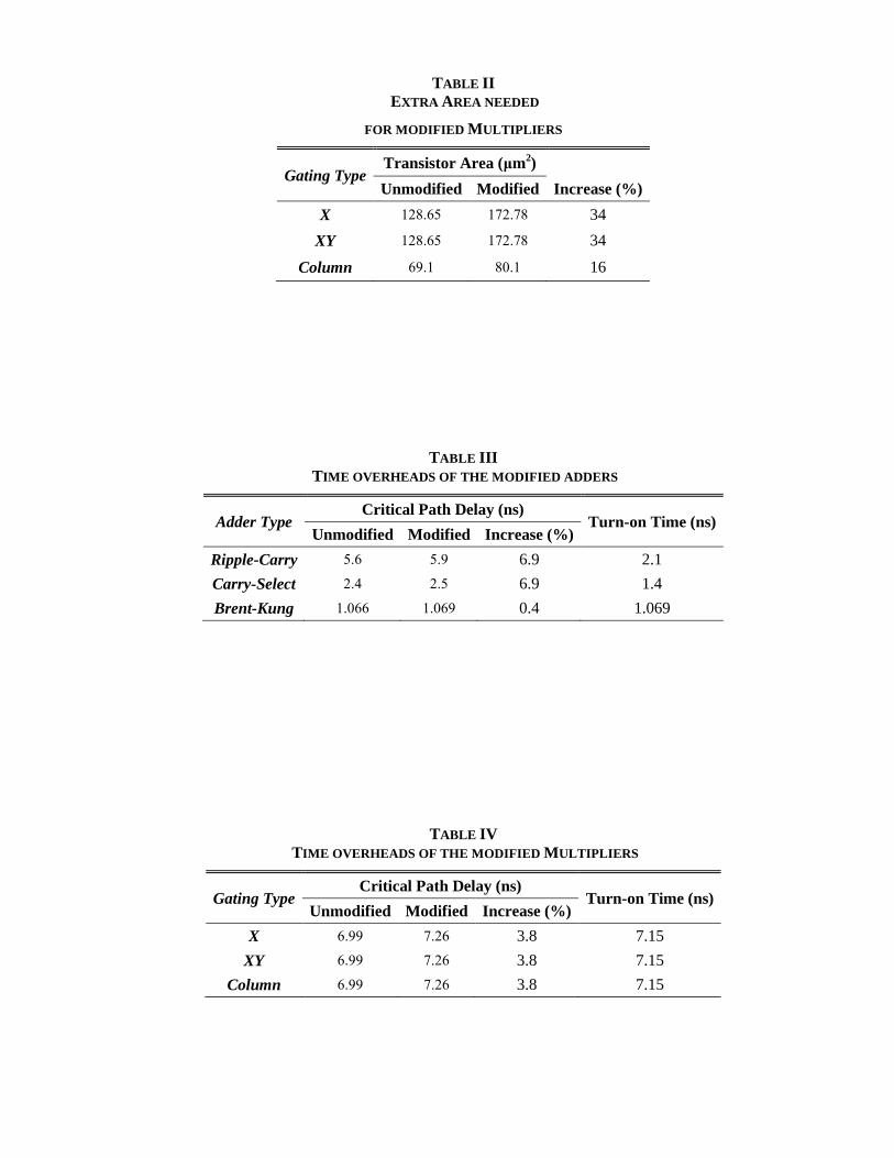
TABLE II
EXTRA AREA NEEDED
FOR MODIFIED MULTIPLIERS
Gating Type Transistor Area (μm
2)
Unmodified Modified Increase (%)
X 128.65 172.78 34
XY 128.65 172.78 34
Column 69.1 80.1 16
TABLE III
TIME OVERHEADS OF THE MODIFIED ADDERS
Adder Type Critical Path Delay (ns)
Turn-on Time (ns) Unmodified Modified Increase (%)
Ripple-Carry 5.6 5.9 6.9 2.1
Carry-Select 2.4 2.5 6.9 1.4
Brent-Kung 1.066 1.069 0.4 1.069
TABLE IV
TIME OVERHEADS OF THE MODIFIED MULTIPLIERS
Gating Type Critical Path Delay (ns)
Turn-on Time (ns) Unmodified Modified Increase (%)
X 6.99 7.26 3.8 7.15
XY 6.99 7.26 3.8 7.15
Column 6.99 7.26 3.8 7.15
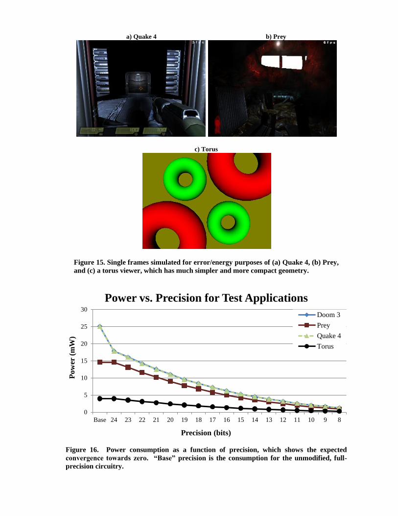
a) Quake 4 b) Prey
c) Torus
Figure 15. Single frames simulated for error/energy purposes of (a) Quake 4, (b) Prey,
and (c) a torus viewer, which has much simpler and more compact geometry.
Figure 16. Power consumption as a function of precision, which shows the expected
convergence towards zero. “Base” precision is the consumption for the unmodified, full-
precision circuitry.
0
5
10
15
20
25
30
89101112131415161718192021222324Base
Pow
er (
mW
)
Precision (bits)
Power vs. Precision for Test Applications
Doom 3
Prey
Quake 4
Torus

Figure 17. Energy-Precision tradeoff curves for all simulated applications at 640x480 pixels
(note the log scale on the Error axis). At the far left of each data set is the data point for 8
bits of precision, increasing by one to the right, with 24 bits of precision (0 error)
represented on the far right of each set with an error of 0.0001 pixels due to the logarithmic
scaling. Error is the screen-space distance between full- and reduced-precision vertices.
0.0001
0.001
0.01
0.1
1
10
100
0 0.2 0.4 0.6 0.8 1
Err
or
(pix
els)
Normalized Energy
Energy-Precision Tradeoff Curves
Doom 3
Prey
Quake 4
Torus

BIOGRAPHIES
Jeff Pool received his B.S. degree in Electrical Engineering from the University of South Carolina in
2007 and his M.S. degree in Computer Science from the University of North Carolina in 2009. He is
currently a Ph.D. candidate in Computer Science at UNC with research interests in the areas of low-
power graphics hardware and architectures.
Anselmo Lastra is Professor and Chair of the Department of Computer Science at the University of
North Carolina at Chapel Hill. He received a BS in Electrical Engineering from the Georgia Institute
of Technology, and MS and PhD degrees in Computer Science from Duke University. He has
chaired a number of conferences, including I3D and Graphics Hardware, and is an associate editor of
IEEE Computer Graphics and Applications. His research interests are in the areas of image-based
modeling and rendering, and graphics hardware architectures.
Montek Singh is an Associate Professor in the Department of Computer Science at the University of
North Carolina at Chapel Hill. He received the B.Tech. degree in Electrical Engineering from IIT
Delhi, Delhi, India, and the Ph.D. degree in Computer Science from Columbia University, New York.
His research interests include asynchronous circuits and systems, CAD tools, high-speed and low-
power design, and application to graphics hardware. He was Program Committee Co-Chair for
ASYNC-07, the General Chair for ASYNC-09, and is a co-Guest Editor of upcoming specials issues
on asynchronous design of ACM JETC and IEEE Design & Test.
Related Documents