POLYMER NANOENCAPSULATED SURFACTANT TEMPLATED AEROGEL CORE COMPOSITES FOR MULTIFUNCTIONAL APPLICATION By KAHKIT CHAN Bachelor of Science in Mechanical Engineering Oklahoma State University Stillwater, Oklahoma 2006 Submitted to the Faculty of the Graduate College of the Oklahoma State University in partial fulfillment of the requirements for the Degree of MASTER OF SCIENCE JULY, 2009

Welcome message from author
This document is posted to help you gain knowledge. Please leave a comment to let me know what you think about it! Share it to your friends and learn new things together.
Transcript
POLYMER NANOENCAPSULATED
SURFACTANT TEMPLATED AEROGEL
CORE COMPOSITES FOR
MULTIFUNCTIONAL
APPLICATION
By
KAHKIT CHAN
Bachelor of Science in
Mechanical Engineering
Oklahoma State University
Stillwater, Oklahoma
2006
Submitted to the Faculty of the Graduate College of the
Oklahoma State University in partial fulfillment of the requirements for
the Degree of MASTER OF SCIENCE
JULY, 2009
POLYMER NANOENCAPSULATED
SURFACTANT TEMPLATED AEROGEL
CORE COMPOSITES FOR
MULTIFUNCTIONAL
APPLICATION
Thesis Approved:
Dr. Hongbing Lu
Thesis Adviser
Dr. Raman P. Singh
Dr. J. Keith Good
Dr. A. Gordon Emslie
Dean of the Graduate College
ACKNOWLEDGMENTS
I would like to thank a number of people who played a key role in this project:
Dr. Hongbing Lu served as my advisor in this project. He also supported me financially
throughout this project and also during my graduate studies at Oklahoma State University.
Besides, the generosity and appreciated guidance he has contributed to this project are
wordless.
Oklahoma Center for the Advancement of Science & Technology for sponsoring the
project.
Dr. Raman P. Singh served as my thesis committee member and has given me a lot of
knowledge on composite from the Advanced Composite course.
Dr. J. Keith Good served as my thesis committee member and has given me the
knowledge on finite element analysis.
All of my colleagues shared the most important thoughts and ideas during the group
meeting. Special thanks go to Boshen Fu on finite element analysis and Kaylan Vengala
on acoustic test.

I would like to thank all of my family members for their support and encouragement,
especially my parents. Last but not least, I would also like to thank my wife and a year
old son for their priceless support and I also need to apologize for not having enough time
at home or just staying in front of a computer typing all the time.
ii
TABLE OF CONTENTS
Chapter Page I. INTRODUCTION............................................................................................................1
1.1 Background................................................................................................................1 1.2 Literature Review ......................................................................................................4 1.3 Scope of this work .....................................................................................................6
II. FABRICATION..............................................................................................................7
2.1 Polymer Crosslinked Aerogels ..................................................................................7 2.2 Preparation of Crosslinked Aerogels .........................................................................8 2.3 Aerogel Embedded in Nomex Honeycomb.............................................................11 2.4 Composite Lay-up....................................................................................................13 2.5 Testing Specimen Preparation .................................................................................14
III. MECHANICAL CHARACTERIZATION .................................................................18
3.1 Three-point Bending Experiment ............................................................................18 3.2 Results and Discussions...........................................................................................19 3.3 Analysis ...................................................................................................................23 3.4 Finite Element Analysis...........................................................................................28
IV. ACOUSTIC CHARACTERIZATION........................................................................34
4.1 Normal Incidence Sound Absorption Coefficient ...................................................34 4.1.1 Requirement......................................................................................................35 4.1.2 Calculation ........................................................................................................37 4.1.3 Results and Discussions....................................................................................40
4.2 Sound Transmission Loss ........................................................................................44 4.2.1 Calculations.......................................................................................................45 4.2.2 Results and Discussion .....................................................................................49
V. CONCLUSION.............................................................................................................53
5.1 Conclusion ...............................................................................................................53

iii
Chapter Page
VI. FUTURE WORK.........................................................................................................55
REFERENCES ..................................................................................................................57
APPENDICES ...................................................................................................................61
A.1 Material Properties..................................................................................................61 A.2 Matlab Code............................................................................................................62
iv
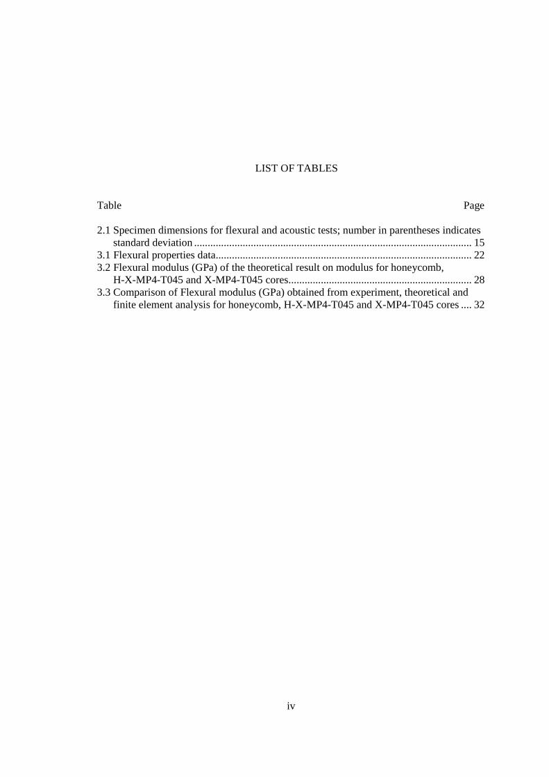
LIST OF TABLES Table Page
2.1 Specimen dimensions for flexural and acoustic tests; number in parentheses indicates standard deviation ....................................................................................................... 15 3.1 Flexural properties data............................................................................................... 22 3.2 Flexural modulus (GPa) of the theoretical result on modulus for honeycomb, H-X-MP4-T045 and X-MP4-T045 cores.................................................................... 28 3.3 Comparison of Flexural modulus (GPa) obtained from experiment, theoretical and finite element analysis for honeycomb, H-X-MP4-T045 and X-MP4-T045 cores .... 32
v
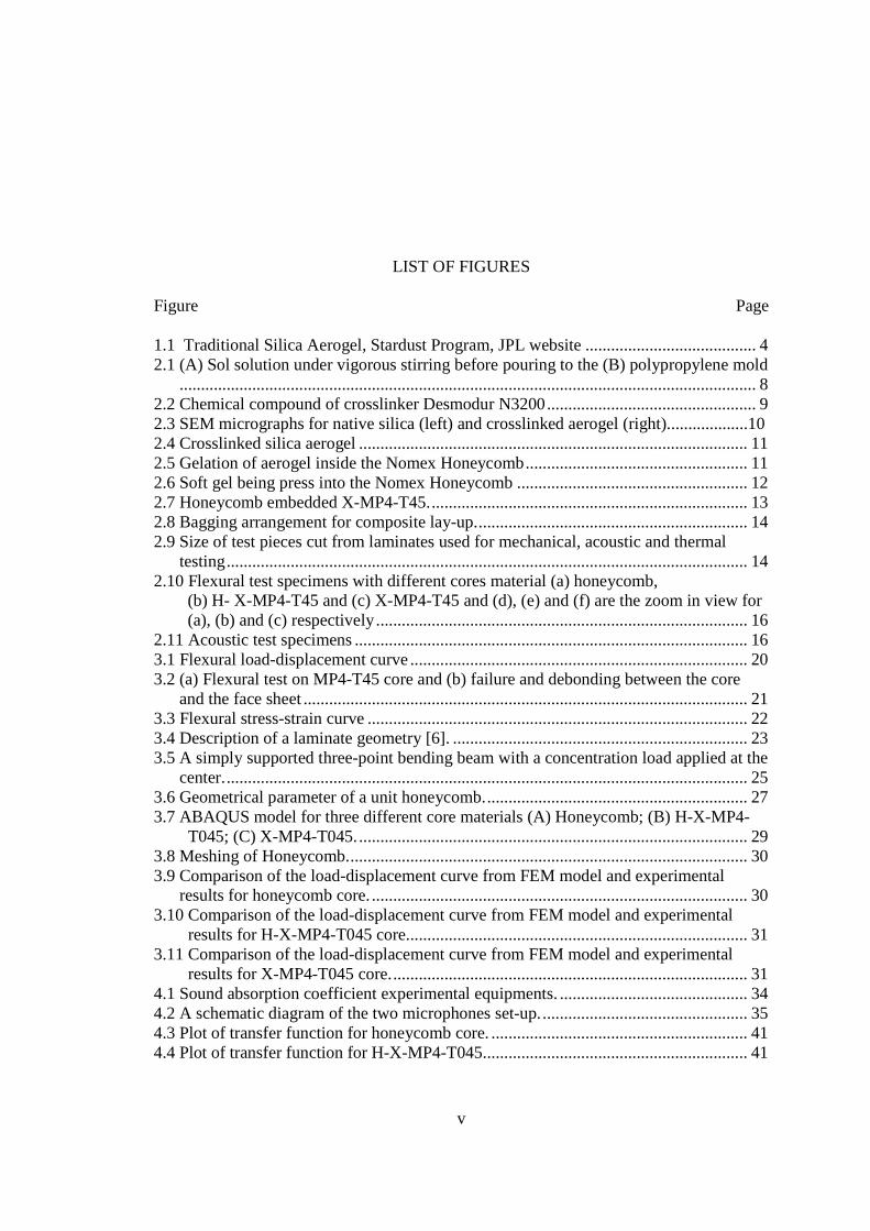
LIST OF FIGURES
Figure Page
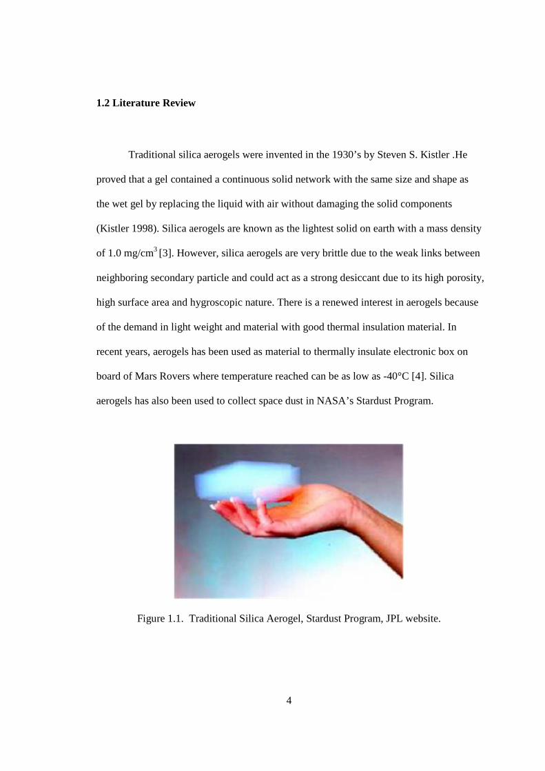
1.1 Traditional Silica Aerogel, Stardust Program, JPL website ........................................4 2.1 (A) Sol solution under vigorous stirring before pouring to the (B) polypropylene mold ....................................................................................................................................... 8 2.2 Chemical compound of crosslinker Desmodur N3200................................................. 9 2.3 SEM micrographs for native silica (left) and crosslinked aerogel (right)...................10 2.4 Crosslinked silica aerogel ........................................................................................... 11 2.5 Gelation of aerogel inside the Nomex Honeycomb....................................................11 2.6 Soft gel being press into the Nomex Honeycomb ...................................................... 12 2.7 Honeycomb embedded X-MP4-T45........................................................................... 13 2.8 Bagging arrangement for composite lay-up................................................................ 14 2.9 Size of test pieces cut from laminates used for mechanical, acoustic and thermal testing.......................................................................................................................... 14 2.10 Flexural test specimens with different cores material (a) honeycomb,
(b) H- X-MP4-T45 and (c) X-MP4-T45 and (d), (e) and (f) are the zoom in view for (a), (b) and (c) respectively....................................................................................... 16
2.11 Acoustic test specimens ............................................................................................ 16 3.1 Flexural load-displacement curve ............................................................................... 20 3.2 (a) Flexural test on MP4-T45 core and (b) failure and debonding between the core and the face sheet ........................................................................................................ 21 3.3 Flexural stress-strain curve ......................................................................................... 223.4 Description of a laminate geometry [6]. ..................................................................... 23 3.5 A simply supported three-point bending beam with a concentration load applied at the center........................................................................................................................... 25 3.6 Geometrical parameter of a unit honeycomb.............................................................. 27 3.7 ABAQUS model for three different core materials (A) Honeycomb; (B) H-X-MP4-
T045; (C) X-MP4-T045............................................................................................ 29 3.8 Meshing of Honeycomb.............................................................................................. 30 3.9 Comparison of the load-displacement curve from FEM model and experimental results for honeycomb core. ........................................................................................ 30 3.10 Comparison of the load-displacement curve from FEM model and experimental
results for H-X-MP4-T045 core................................................................................ 31 3.11 Comparison of the load-displacement curve from FEM model and experimental
results for X-MP4-T045 core.................................................................................... 31 4.1 Sound absorption coefficient experimental equipments. ............................................ 34 4.2 A schematic diagram of the two microphones set-up.................................................35 4.3 Plot of transfer function for honeycomb core. ............................................................ 41 4.4 Plot of transfer function for H-X-MP4-T045.............................................................. 41
vi
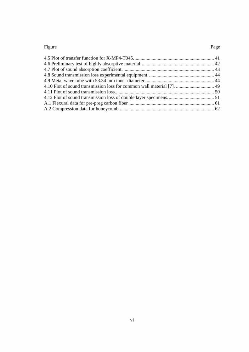
Figure Page
4.5 Plot of transfer function for X-MP4-T045.................................................................. 41 4.6 Preliminary test of highly absorptive material............................................................ 42 4.7 Plot of sound absorption coefficient. .......................................................................... 43 4.8 Sound transmission loss experimental equipment...................................................... 44 4.9 Metal wave tube with 53.34 mm inner diameter. ....................................................... 44 4.10 Plot of sound transmission loss for common wall material [7]. ............................... 49 4.11 Plot of sound transmission loss................................................................................. 50 4.12 Plot of sound transmission loss of double layer specimens...................................... 51 A.1 Flexural data for pre-preg carbon fiber ...................................................................... 61 A.2 Compression data for honeycomb.............................................................................. 62
1
CHAPTER I
INTRODUCTION
1.1 Background Aerogels are low-density, highly porous, nanostructured materials (Pierre and
Pajonk, 2002). There are primarily three types of aerogels: inorganic, organic and carbon
aerogels. Inorganic aerogels are formed by supercritical fluid (SCF) drying of wet gels
(i.e., solvent-filled gels) synthesized through a sol-gel process by hydrolysis and
polycondensation of metal and semimetal alkoxides. During SCF drying, gelation
solvents are first replaced by liquid CO2 that is taken supercritical (i.e. above the critical
point of CO2) and is vented off. Among inorganic aerogels, silica aerogels are the most
well-known. However, their engineering application is very limited due to extreme
brittleness and hydrophilicity (Fricke, 1988; Woignier and Reynes, 1998; Pierre and
Pajonk, 2002; Miner and Hosticka, 2004). The aerogel fragility is traced to the weak links
in the aerogel skeletal framework, which are the inter-nanoparticle necks in the ‘pearl-
necklace’ network structure. Based on the premise that polymer-nanoparticle composites
show properties above and beyond those of the individual components (Thayer and
Houston, 2003), recently a new kind of strong lightweight aerogel was developed by
encapsulating the skeletal aerogel nanoparticles under a thin (∼2 nm thick) layer of
2
polymer (Leventis et al., 2002, 2005; Zhang et al., 2004; Bertino et al., 2004; Meador et
al., 2005; Katti et al., 2006). Polymers such as polyurethanes, polyureas, epoxies and
polystyrene, coat conformally the surface of the aerogel skeleton, thus retaining the
mesoporous structure while the interparticle necks get wider. The process that furnishes
the new material is referred to as crosslinking and the new material is referred to as
crosslinked silica aerogel (CSA). The polymer crosslinked aerogel (X-Aerogels) can be
up to three times more dense, but more than 300 times stronger, and less than one tenth as
hydrophilic as native aerogels. With low thermal conductivity, high acoustic damping,
ease in fabrication, X-Aerogels has potential in engineering applications as lightweight
structural materials. Thus, the characteristic of aerogels as core material in sandwich
structures were investigated in this paper.
Sandwich constructions have been widely used in different applications in many
areas. These high strength-weight ratio structures have been slowly replacing monolithic
materials in many engineering applications. It goes even further as certain mechanical
and bulk properties can be tailored to properties not yet available in a single material.
Sandwich structures can be designed to have addressed the needs in many applications.
The flexibility of designs can range from the number and orientation of plies in the face
sheets, the thickness of the core in the sandwich structure and more importantly, the
different core materials used.
In a sandwich construction, it consists of at least two plies of faces sheet, top and
bottom face sheets sandwiching a core. The common face sheet materials in the structures
3
contain two or more distinct constituent materials or phases known as composite. The
commonly used composite materials are plastics, woods and metals. As for the core
material, metal in the form of foam or honeycomb, and Nomex paper in the form of
honeycomb are the most widely used in the primary structural application.
The sandwich constructions involved combination of different materials and each
material will give advantage and disadvantage to the mechanical properties. For example,
some of the critical factors are the bonding strength between the face sheets and core,
buckling of sandwich structure and composite, etc. Among all of these factors, failure
modes are always reported in composite testing as failure loads are closely related to
failure modes.
In this study, Nomex honeycomb and a highly porous low-density material known
as corosslinked aerogels were used as the core material in a sandwich construction. The
aerogel used in this work was polyurea crosslinked surfactant templated silica aerogel,
designated as X-MP4-T045 with high compressive strength [2]. A study was conducted
with using three different types of cores, which are Nomex honeycomb, crosslinked
aerogel embedded in Nomex honeycomb, and crosslinked aerogel core. In this paper, as
for convenience in writing, the Nomex honeycomb, crosslinked aerogel embedded in
Nomex honeycomb and crossljnked aerogel are designated as honeycomb, H-X-MP4-
T045 and X-MP4-T045 respectively.
4
1.2 Literature Review Traditional silica aerogels were invented in the 1930’s by Steven S. Kistler .He
proved that a gel contained a continuous solid network with the same size and shape as
the wet gel by replacing the liquid with air without damaging the solid components
(Kistler 1998). Silica aerogels are known as the lightest solid on earth with a mass density
of 1.0 mg/cm3 [3]. However, silica aerogels are very brittle due to the weak links between
neighboring secondary particle and could act as a strong desiccant due to its high porosity,
high surface area and hygroscopic nature. There is a renewed interest in aerogels because
of the demand in light weight and material with good thermal insulation material. In
recent years, aerogels has been used as material to thermally insulate electronic box on
board of Mars Rovers where temperature reached can be as low as -40°C [4]. Silica
aerogels has also been used to collect space dust in NASA’s Stardust Program.
Figure 1.1. Traditional Silica Aerogel, Stardust Program, JPL website.
5
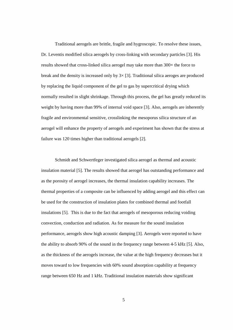
Traditional aerogels are brittle, fragile and hygroscopic. To resolve these issues,
Dr. Leventis modified silica aerogels by cross-linking with secondary particles [3]. His
results showed that cross-linked silica aerogel may take more than 300× the force to
break and the density is increased only by 3× [3]. Traditional silica aeroges are produced
by replacing the liquid component of the gel to gas by supercritical drying which
normally resulted in slight shrinkage. Through this process, the gel has greatly reduced its
weight by having more than 99% of internal void space [3]. Also, aerogels are inherently
fragile and environmental sensitive, crosslinking the mesoporus silica structure of an
aerogel will enhance the property of aerogels and experiment has shown that the stress at
failure was 120 times higher than traditional aerogels [2].
Schmidt and Schwertfeger investigated silica aerogel as thermal and acoustic
insulation material [5]. The results showed that aerogel has outstanding performance and
as the porosity of aerogel increases, the thermal insulation capability increases. The
thermal properties of a composite can be influenced by adding aerogel and this effect can
be used for the construction of insulation plates for combined thermal and footfall
insulations [5]. This is due to the fact that aerogels of mesoporous reducing voiding
convection, conduction and radiation. As for measure for the sound insulation
performance, aerogels show high acoustic damping [3]. Aerogels were reported to have
the ability to absorb 90% of the sound in the frequency range between 4-5 kHz [5]. Also,
as the thickness of the aerogels increase, the value at the high frequency decreases but it
moves toward to low frequencies with 60% sound absorption capability at frequency
range between 650 Hz and 1 kHz. Traditional insulation materials show significant
6
decrease in sound insulation at lower frequency range [5]. In order to obtain better results
in this area, many researchers have modified aerogels by varying the solvent with
different volume concentration [2, 3]. In some applications, aerogels can be used directly
but most of the times when the requirement of mechanical strength is high, aerogels are
used with other materials with higher mechanical strength and toughness [5].
1.3 Scope of this work
In this work, processes are developed to prepare aerogel composite sandwich
structure to provide multifunctionality. The aerogel sandwich structures will be
characterized to determine their acoustic and mechanical properties. The sound
absorption coefficient and sound transmission loss are measured by an impedance tube,
with the use of two and four microphones set-up, an oscilloscope and a noise generator.
The measurement of sound absorption coefficient follows the ASTM E-1050 standard
and sound transmission loss in “Measurement of transmission loss of materials using a
standing wave tube” by Oliviero Olivieri, J. Stuart Bolton and TaewookYoo [1] that is
similar to ASTM E-1050.
For mechanical testing, flexural test was used to evaluate the strength and
stiffness of aerogel composite structure in three point bending. The results are compared
with conventional Nomex core composites. Experimental data are compared with
analytical and numerical results.
7
CHAPTER II
FABRICATION
2.1 Polymer Crosslinked Aerogels
The pre-preg FSG 584 (unidirectional woven carbon fiber) embedded F155 resin
were provided by Hexcel Composites (Bedford, TX 76022) and 3 lb density Nomex
honeycombs were purchased from Applied Vehicle Technology (Indianapolis, IN 46218).
Polypropylene molds were purchased from Melmatinc, model number (P-084). Acetone,
acetonitrile, and alcohol were all purchased from Pharmaco Chemical Company
(Brookfield, CT 06804), Nitric acid was purchased from Seastar Chemical Inc.
(Pittsburgh, PA 15275), tetramethylorthosilicate (TMOS) and 1.3.5-trimethylbenzene
(TMB) were purchased from Sigma-Aldrich (St. Louis, MO 63103), and Pluronic P123
(tri-block co-polymer: PEO20PPO70PEO20) was supplied by Acros Organics (New Jersey).
Research samples of Desmodur N3200, a hexamethylene diisocyanate oligomer, were
provided by Bayer (Pittsburgh, PA 15205).
8
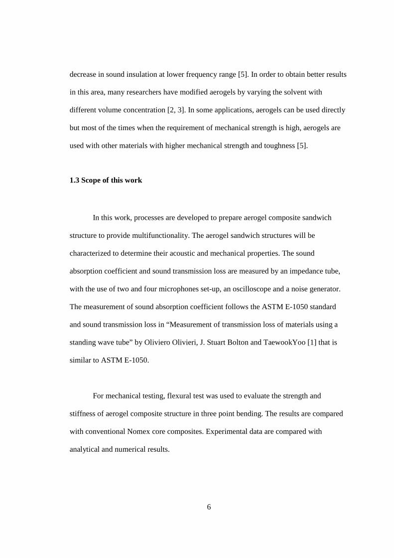
2.2 Preparation of Crosslinked Aerogels The aerogels used in this study were synthesized using the same procedures as
used by Leventis group. They are labeled following Leventis notation [3]. For example,
for aerogel as X-MP4-T45, ‘X’ indicates crosslinked, ‘P4’ and T45 stand for 4 g of
Pluronic P123 and 0.45g of TMB, respectively. In this procedure, 4.0 g of Pluronic P123
(C5H10O2) was dissolved in 12 g of 1.0 M aqueous solution of nitric acid (HNO3) under
magnetic stirring for 8 hours. Under vigorous stirring, 0.45 g of Tetramethylbenzidine
known as TMB (C16H26Cl2N2O2) was added to the solution for 30 min. The solution was
cooled to 0°C and 5.15 g of Tetramethoxyl silane known as TMOS Si(CH3)4 was added
to the solution after another 30 min.
A
B
Figure 2.1. (A) Sol solution under vigorous stirring before pouring to the (B) polypropylene mold.
The pre-cooling was to avoid crosslinker TMOS to react quickly with other agents
and this is due to the boiling point of TMOS which is 26.6C. Mixing the two agents at
9
room temperature would lead to an increase in temperature which will result in gelation
being immediately taken place before the solution was thoroughly mixed. After stirring
for 10 min, the solutions were poured into a polypropylene mold. The mold was then
closed with the lid, sealed with PTFE tape to avoid evaporation of the liquid and kept
inside the oven at 60 °C for gelation. The sample was monitored every 10 to 15 min until
gelation was complete and the sample was then aged at 60°C for 5× the gelation time
which was about 12 h. The wet gel was removed from the mold and placed into ethanol
with the amount of 4× the volume of the gels to remove residual water. At this stage, the
wet gel is extremely fragile. Ethanol was changed 2× at 8 h intervals. The sample went
through Soxhlet extraction which is similar to distillation process by using CH3CN as
solvent for 2 days to remove P123. Recent results from Dr Letentis group show that the
pre-crosslinking washes may be eliminated but to get the sample which is identical to the
previous work, the wet gel was washed. Acetone was used to wash the sample 4× with 8
h intervals. After washing with acetone, the sample was crosslinked with acetone
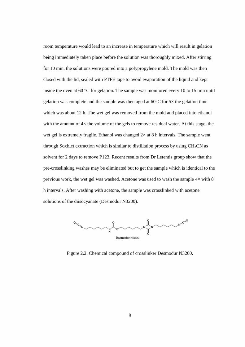
solutions of the diisocyanate (Desmodur N3200).
Figure 2.2. Chemical compound of crosslinker Desmodur N3200.
10
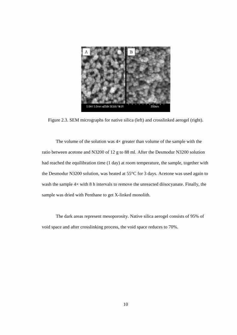
Figure 2.3. SEM micrographs for native silica (left) and crosslinked aerogel (right).
The volume of the solution was 4× greater than volume of the sample with the
ratio between acetone and N3200 of 12 g to 88 ml. After the Desmodur N3200 solution
had reached the equilibration time (1 day) at room temperature, the sample, together with
the Desmodur N3200 solution, was heated at 55°C for 3 days. Acetone was used again to
wash the sample 4× with 8 h intervals to remove the unreacted diisocyanate. Finally, the
sample was dried with Penthane to get X-linked monolith.
The dark areas represent mesoporosity. Native silica aerogel consists of 95% of
void space and after crosslinking process, the void space reduces to 70%.
11
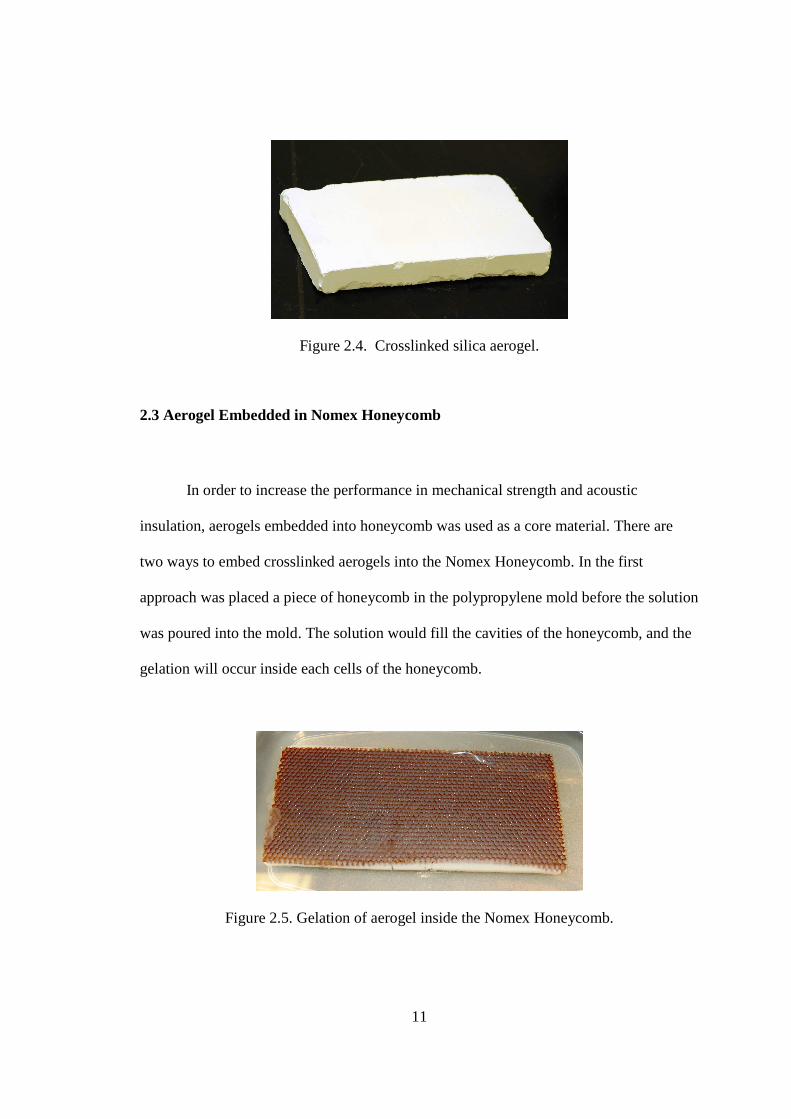
Figure 2.4. Crosslinked silica aerogel.
2.3 Aerogel Embedded in Nomex Honeycomb
In order to increase the performance in mechanical strength and acoustic
insulation, aerogels embedded into honeycomb was used as a core material. There are
two ways to embed crosslinked aerogels into the Nomex Honeycomb. In the first
approach was placed a piece of honeycomb in the polypropylene mold before the solution
was poured into the mold. The solution would fill the cavities of the honeycomb, and the
gelation will occur inside each cells of the honeycomb.
Figure 2.5. Gelation of aerogel inside the Nomex Honeycomb.
12
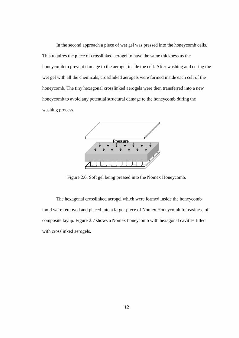
In the second approach a piece of wet gel was pressed into the honeycomb cells.
This requires the piece of crosslinked aerogel to have the same thickness as the
honeycomb to prevent damage to the aerogel inside the cell. After washing and curing the
wet gel with all the chemicals, crosslinked aerogels were formed inside each cell of the
honeycomb. The tiny hexagonal crosslinked aerogels were then transferred into a new
honeycomb to avoid any potential structural damage to the honeycomb during the
washing process.
Figure 2.6. Soft gel being pressed into the Nomex Honeycomb.
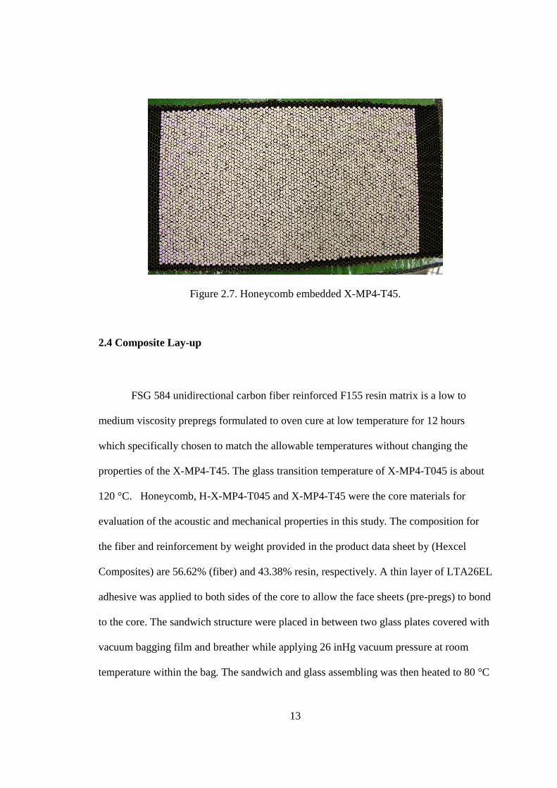
The hexagonal crosslinked aerogel which were formed inside the honeycomb
mold were removed and placed into a larger piece of Nomex Honeycomb for easiness of
composite layup. Figure 2.7 shows a Nomex honeycomb with hexagonal cavities filled
with crosslinked aerogels.
PressurePressure
13
Figure 2.7. Honeycomb embedded X-MP4-T45.
2.4 Composite Lay-up
FSG 584 unidirectional carbon fiber reinforced F155 resin matrix is a low to
medium viscosity prepregs formulated to oven cure at low temperature for 12 hours
which specifically chosen to match the allowable temperatures without changing the
properties of the X-MP4-T45. The glass transition temperature of X-MP4-T045 is about
120 °C. Honeycomb, H-X-MP4-T045 and X-MP4-T45 were the core materials for
evaluation of the acoustic and mechanical properties in this study. The composition for
the fiber and reinforcement by weight provided in the product data sheet by (Hexcel
Composites) are 56.62% (fiber) and 43.38% resin, respectively. A thin layer of LTA26EL
adhesive was applied to both sides of the core to allow the face sheets (pre-pregs) to bond
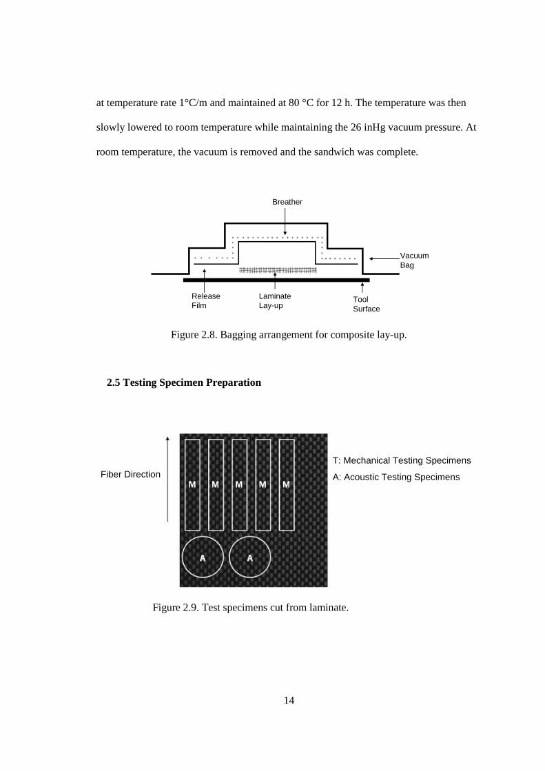
to the core. The sandwich structure were placed in between two glass plates covered with
vacuum bagging film and breather while applying 26 inHg vacuum pressure at room
temperature within the bag. The sandwich and glass assembling was then heated to 80 °C
14
at temperature rate 1°C/m and maintained at 80 °C for 12 h. The temperature was then
slowly lowered to room temperature while maintaining the 26 inHg vacuum pressure. At
room temperature, the vacuum is removed and the sandwich was complete.
Breather
Vacuum Bag
Release Film
Laminate Lay-up
Tool Surface
Figure 2.8. Bagging arrangement for composite lay-up.
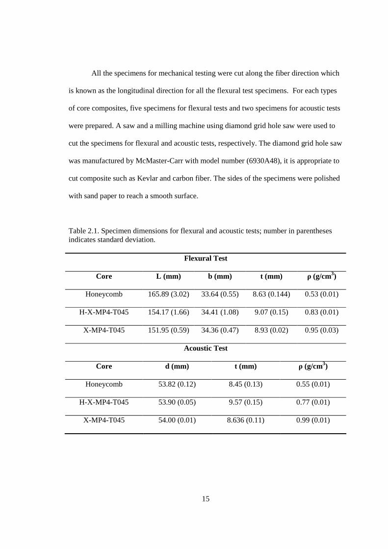
2.5 Testing Specimen Preparation
T: Mechanical Testing Specimens
A: Acoustic Testing SpecimensFiber Direction
Figure 2.9. Test specimens cut from laminate.
15
All the specimens for mechanical testing were cut along the fiber direction which
is known as the longitudinal direction for all the flexural test specimens. For each types
of core composites, five specimens for flexural tests and two specimens for acoustic tests
were prepared. A saw and a milling machine using diamond grid hole saw were used to
cut the specimens for flexural and acoustic tests, respectively. The diamond grid hole saw
was manufactured by McMaster-Carr with model number (6930A48), it is appropriate to
cut composite such as Kevlar and carbon fiber. The sides of the specimens were polished
with sand paper to reach a smooth surface.
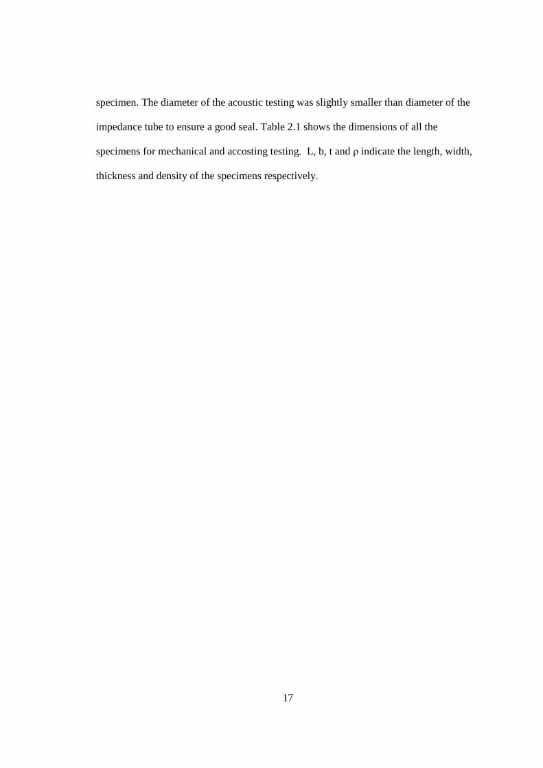
Table 2.1. Specimen dimensions for flexural and acoustic tests; number in parentheses indicates standard deviation.
Flexural Test
Core L (mm) b (mm) t (mm) ρ (g/cm3)
Honeycomb 165.89 (3.02) 33.64 (0.55) 8.63 (0.144) 0.53 (0.01)
H-X-MP4-T045 154.17 (1.66) 34.41 (1.08) 9.07 (0.15) 0.83 (0.01)
X-MP4-T045 151.95 (0.59) 34.36 (0.47) 8.93 (0.02) 0.95 (0.03)
Acoustic Test
Core d (mm) t (mm) ρ (g/cm3)
Honeycomb 53.82 (0.12) 8.45 (0.13) 0.55 (0.01)
H-X-MP4-T045 53.90 (0.05) 9.57 (0.15) 0.77 (0.01)
X-MP4-T045 54.00 (0.01) 8.636 (0.11) 0.99 (0.01)

16
Figure 2.10. Flexural test specimens with different cores material (a) honeycomb, (b) H- X-MP4-T45 and (c) X-MP4-T45 and (d), (e) and (f) are the zoom in view for (a), (b) and (c) respectively.
Figure 2.11. Acoustic test specimens
The dimensions for the flexural specimens followed the ASTM D790 standards.
The specimen’s length for mechanical testing is about 16 times of the thickness. Some
specimens were slightly shorter due to the limitation of the polypropylene mold used to
fabricate X-MP4-T045, but the error difference from the standard length/thickness ratio is
within 5%. The width of the specimen is below four times of the thickness of the
17
specimen. The diameter of the acoustic testing was slightly smaller than diameter of the
impedance tube to ensure a good seal. Table 2.1 shows the dimensions of all the
specimens for mechanical and accosting testing. L, b, t and ρ indicate the length, width,
thickness and density of the specimens respectively.
18
CHAPTER III
MECHANICAL CHARACTERIZATION
3.1 Three-point Bending Experiment
An MTS 810 materials testing system retrofitted with an Instron digital controller
and data acquisition system was used for the flexural test. The load and displacement data
were recorded simultaneously as a function of time. A 5 kN load cell was used for the
entire testing. The testing span length, L, as well as the length/thickness ratio follows the
ASTM D790. The span length, L= 133.35 mm was chosen for all flexural specimens.
Flexural properties of sandwich construction were calculated using elementary
beam theory. The flexural strain was calculated with respect to the deflection of the outer
surface of the test specimen at midspan using
(3.1)
where εf is the strain, on the top face sheet, D is the maximum deflection at the center of
the beam, L is the support span length, and d is the thickness of the specimen.
2/6 LDdf =ε
19
For flexural test, the maximum stress occurs at the midpoint of the specimen. The
stress was calculated from the load at the midspan of the outer surface of the test
specimen using
(3.2)
where σf is the stress on the outer fibers at midpoint, P is the load at the midpoint, and
L is the support span length, d is the thickness of the specimen and b is the width of the
specimen.
The modulus of elasticity was determined using the initial straight line slope of
the load-deflection curve using
(3.3)
where Ef is the modulus of elasticity, m is the slope of the load-displacement cure, L is
the support span length, d is the thickness of the specimen, and b is width of the specimen.
3.2 Results and Discussions
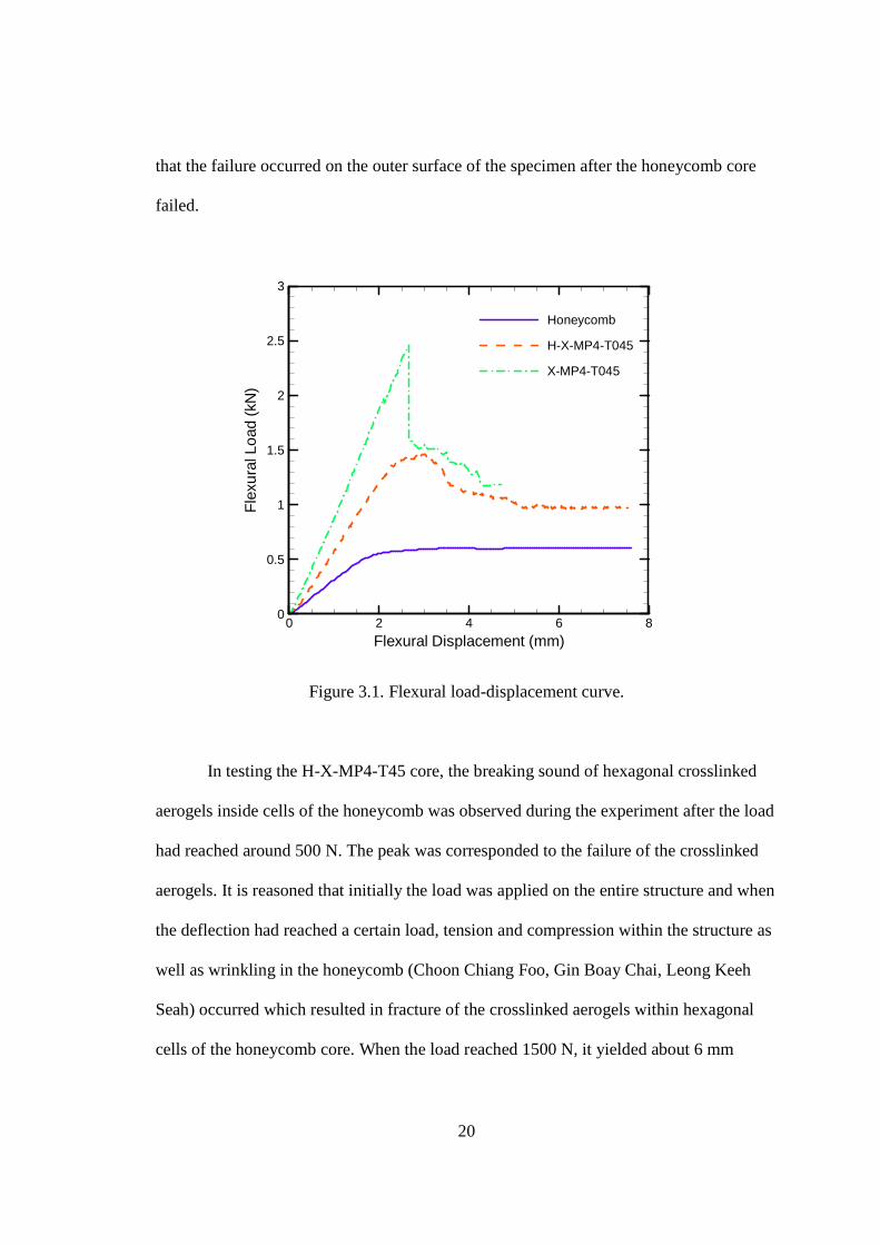
The flexural properties and load-displacement curves for honeycomb, H-X-MP4-
T045 and X-MP4-T45 cores are shown in Table 3.1 and Figure 3.1, respectively. Five
specimens were tested for each type of core material and the average value was obtained
with standard deviation reported in the parentheses. Observation of the testing showed
22/3 bdPLf =σ
33 4/ bdmLE f =
20
that the failure occurred on the outer surface of the specimen after the honeycomb core
failed.
Flexural Displacement (mm)
Fle
xura
lLoa
d(k
N)
0 2 4 6 80
0.5
1
1.5
2
2.5
3
Honeycomb
H-X-MP4-T045
X-MP4-T045
Figure 3.1. Flexural load-displacement curve.
In testing the H-X-MP4-T45 core, the breaking sound of hexagonal crosslinked
aerogels inside cells of the honeycomb was observed during the experiment after the load
had reached around 500 N. The peak was corresponded to the failure of the crosslinked
aerogels. It is reasoned that initially the load was applied on the entire structure and when
the deflection had reached a certain load, tension and compression within the structure as
well as wrinkling in the honeycomb (Choon Chiang Foo, Gin Boay Chai, Leong Keeh
Seah) occurred which resulted in fracture of the crosslinked aerogels within hexagonal
cells of the honeycomb core. When the load reached 1500 N, it yielded about 6 mm
21
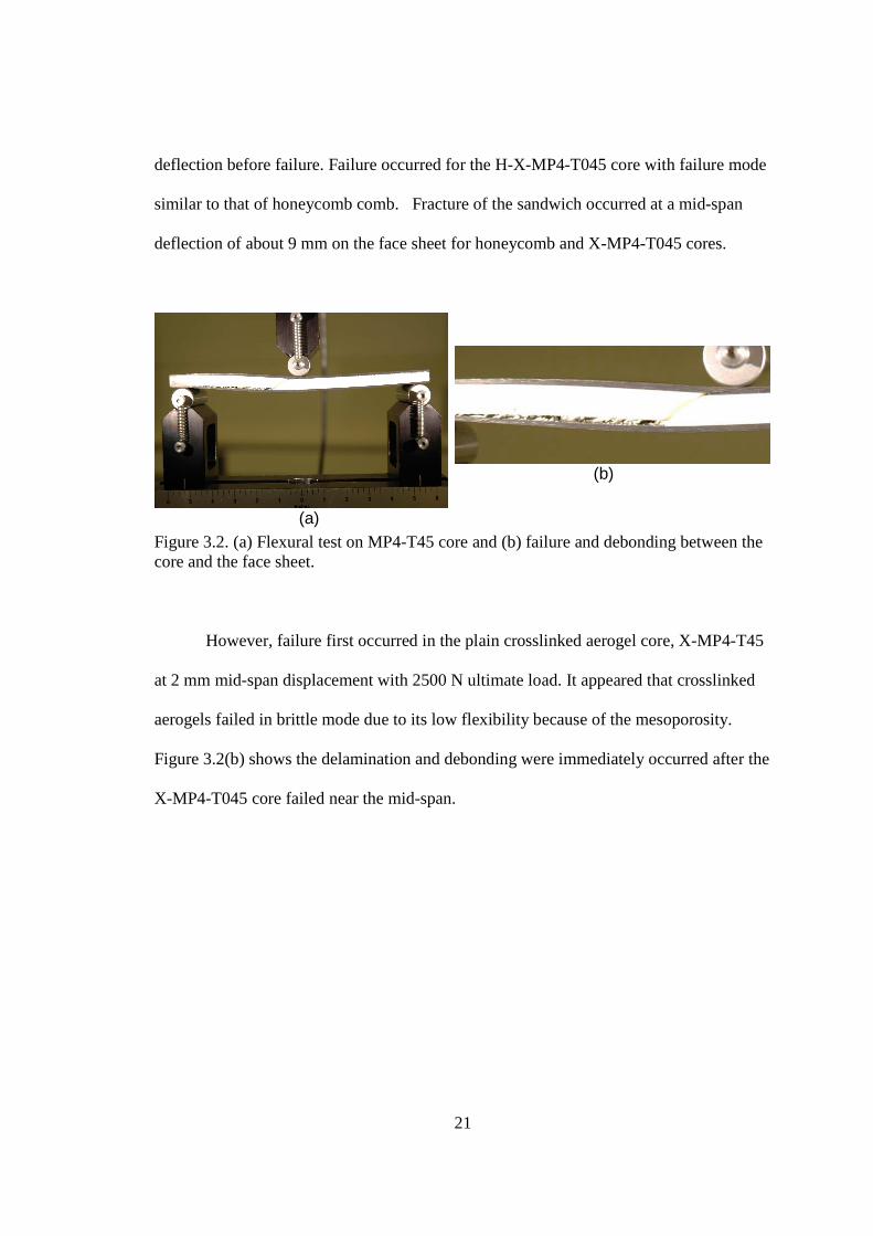
deflection before failure. Failure occurred for the H-X-MP4-T045 core with failure mode
similar to that of honeycomb comb. Fracture of the sandwich occurred at a mid-span
deflection of about 9 mm on the face sheet for honeycomb and X-MP4-T045 cores.
(a)
(b)
Figure 3.2. (a) Flexural test on MP4-T45 core and (b) failure and debonding between the core and the face sheet.
However, failure first occurred in the plain crosslinked aerogel core, X-MP4-T45
at 2 mm mid-span displacement with 2500 N ultimate load. It appeared that crosslinked
aerogels failed in brittle mode due to its low flexibility because of the mesoporosity.
Figure 3.2(b) shows the delamination and debonding were immediately occurred after the
X-MP4-T045 core failed near the mid-span.
22
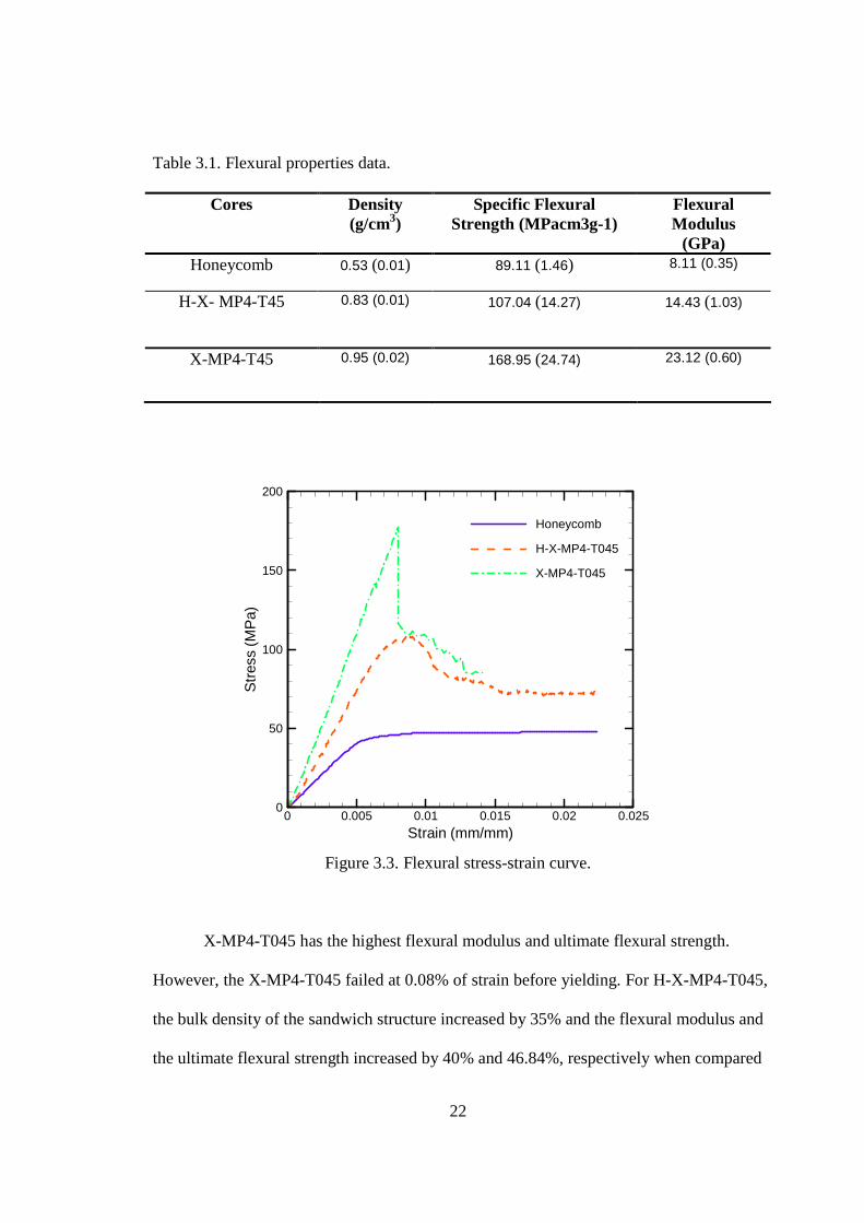
Table 3.1. Flexural properties data.
Cores Density (g/cm3)
Specific Flexural Strength (MPacm3g-1)
Flexural Modulus
(GPa) Honeycomb 0.53 (0.01) 89.11 (1.46) 8.11 (0.35)
H-X- MP4-T45 0.83 (0.01)
107.04 (14.27)
14.43 (1.03)
X-MP4-T45 0.95 (0.02)
168.95 (24.74) 23.12 (0.60)
Strain (mm/mm)
Str
ess
(MP
a)
0 0.005 0.01 0.015 0.02 0.0250
50
100
150
200
Honeycomb
H-X-MP4-T045
X-MP4-T045
Figure 3.3. Flexural stress-strain curve.
X-MP4-T045 has the highest flexural modulus and ultimate flexural strength.
However, the X-MP4-T045 failed at 0.08% of strain before yielding. For H-X-MP4-T045,
the bulk density of the sandwich structure increased by 35% and the flexural modulus and
the ultimate flexural strength increased by 40% and 46.84%, respectively when compared
23
to the honeycomb core composite. Also, the flexural modulus and flexural ultimate
strength were decreased by 37.5% and 44.6% when compared to the X-MP4-T045 but it
resisted more flexural strain before failure.
3.3 Analysis
In this section, elementary beam analysis is used to evaluate the modulus of the
composite. The elementary beam theory, as adapted to sandwich beams was used. In
elementary beam theory, flexural rigidity is the product of the Young’s modulus, E, and
the beam’s moment of inertia about the neutral axis. In this case, the flexural rigidity is
the summation of the values of different layers, measured from the neutral axis.
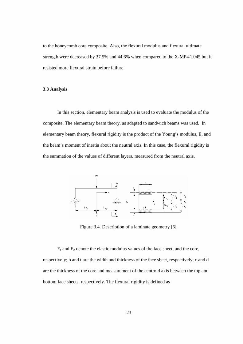
Figure 3.4. Description of a laminate geometry [6].
Ef and Ec denote the elastic modulus values of the face sheet, and the core,
respectively; b and t are the width and thickness of the face sheet, respectively; c and d
are the thickness of the core and measurement of the centroid axis between the top and
bottom face sheets, respectively. The flexural rigidity is defined as
24
(3.4)
where
D= flexural rigidity, Nmm4
t= thicnkness of the face sheet, mm
b = width of the sandwich beam, mm
d = length of centroid axis between top and bottom face sheet, mm
Ef = elastic modulus of the face sheet, MPa
Ec = elastic modulus of the core material, MPa
In order to simplify the equation, the first and third term of the flexural rigidity
can be ignored if the following is satisfied.
(3.5)
The first term is involved of the thickness of the face sheet. If the face sheet is
thin when compared to the sandwich structure, the first term can be canceled and the
equation can be reduced to
(3.6)
(3.7)
1226
323 bcE
btdE
btED cff ++=
77.5>t
d
7.16.3
2
>c
td
E
E
c
f
122
32 bcE
btdED cf +=
25
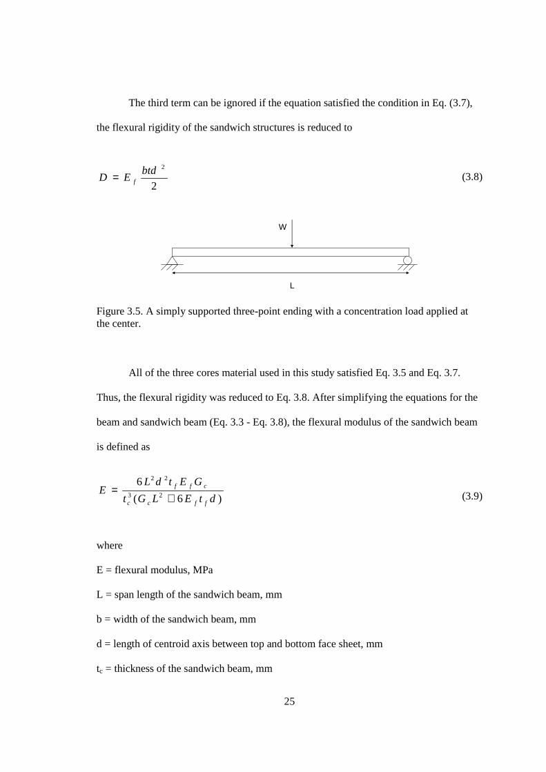
The third term can be ignored if the equation satisfied the condition in Eq. (3.7),
the flexural rigidity of the sandwich structures is reduced to
(3.8)
L
W
Figure 3.5. A simply supported three-point ending with a concentration load applied at the center.
All of the three cores material used in this study satisfied Eq. 3.5 and Eq. 3.7.
Thus, the flexural rigidity was reduced to Eq. 3.8. After simplifying the equations for the
beam and sandwich beam (Eq. 3.3 - Eq. 3.8), the flexural modulus of the sandwich beam
is defined as
(3.9)
where
E = flexural modulus, MPa
L = span length of the sandwich beam, mm
b = width of the sandwich beam, mm
d = length of centroid axis between top and bottom face sheet, mm
tc = thickness of the sandwich beam, mm
2
2btdED f=
)6(
623
22
dtELGt
GEtdLE
ffcc
cff
+=
26
tf = thickness of face sheet, mm
Ef = elastic modulus of the face sheet, MPa
Ec = elastic modulus of the core material, MPa
Gc = shear modulus of the core material, MPa
The shear modulus of the H-X-MP4-T045 follows the equation to calculate the
shear modulus of composite material. However, this equation is limited to two material
constituents in the composite. The equation is defined as
(3.10)
(3.11)
(3.12)
where
G = shear modulus of the core, MPa
GH = shear modulus of Nomex honeycomb, MPa
GA = shear modulus of aerogel, MPa
VH = volume fractions of honeycomb, ratio
VA = volume fraction of aerogel, ratio
v = total volume of the core, mm3
vH = volume of honeycomb, mm3
vA = volume of aerogel, mm3
HAAH
HA
VGVG
GGG
+=
AH vvv +=
v
vV
v
vV A
AH
H ==
27
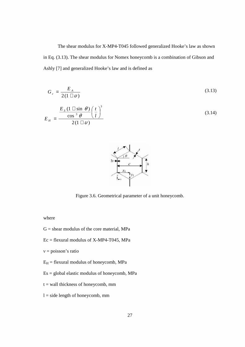
The shear modulus for X-MP4-T045 followed generalized Hooke’s law as shown
in Eq. (3.13). The shear modulus for Nomex honeycomb is a combination of Gibson and
Ashly [7] and generalized Hooke’s law and is defined as
(3.13)
(3.14)
Figure 3.6. Geometrical parameter of a unit honeycomb. where
G = shear modulus of the core material, MPa
Ec = flexural modulus of X-MP4-T045, MPa
ν = poisson’s ratio
EH = flexural modulus of honeycomb, MPa
Es = global elastic modulus of honeycomb, MPa
t = wall thickness of honeycomb, mm
l = side length of honeycomb, mm
)1(2 υ+= A
c
EG
)1(2cos
)sin1(3
3
υθ
θ
+
+
= l
tE
E
S
H
28
Table 3.2. Flexural modulus (GPa) of the theoretical result on modulus for honeycomb, H-X-MP4-T045 and X-MP4-T045 cores.
Honeycomb H-X-MP4-T045 X-MP4-T045
Theoretical 8.90 22.05 24.70
3.4 Finite Element Analysis
Commercial software ABAQUS was used to model the characteristic of the
sandwich structures under flexural load. The mechanical properties were determined
using flexural test for pre-preg carbon fiber and compression test for Nomex honeycomb
and X-MP4-T045. The mechanical properties involved in these simulations are elastic
and plastic properties for each material. To define the plasticity in Abaqus, true stress,
true stain and plasticity equation were used as shown in Eq (3.15).
(3.15)
where
εpl = plastic strain, mm/mm
εt = true strain, mm/mm
σ = true stress, MPa
E = Young’s modulus, MPa
Et
pl
σεε −=
29
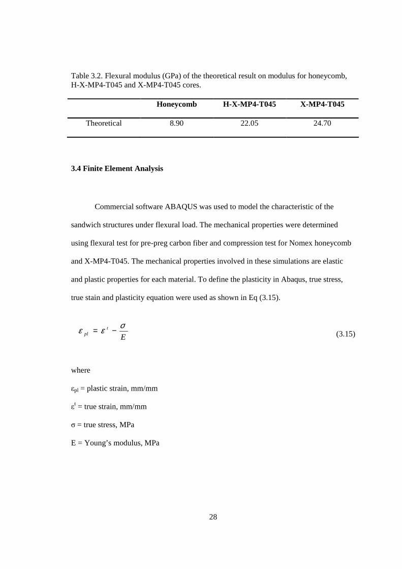
Figure 3.7. ABAQUS model for the three different core materials (A) Honeycomb; (B) H-X-MP4-T045; (C) X-MP4-T045.
One quarter of the samples was simulated because of symmetry as shown in
Figure 3.7. The dimension of all the specimens and the fixtures followed exactly the same
as experimental conditions. Materials used in this simulation were modeled using solid
extractable elements and the loading fixtures were modeled with shell elements with
reference points to define the loading and boundary conditions. The displacement was
applied at the top of the roller and the displacements at the bottom roller were set to zero.
30
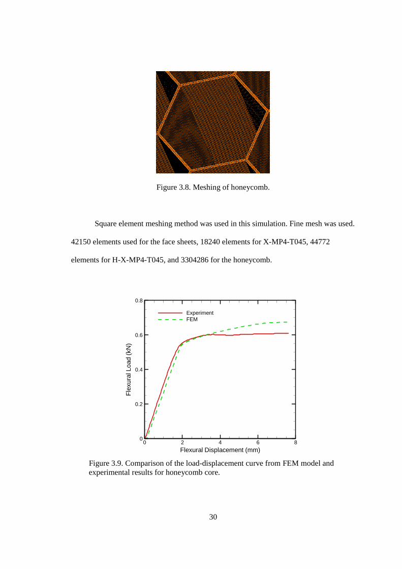
Figure 3.8. Meshing of honeycomb.
Square element meshing method was used in this simulation. Fine mesh was used.
42150 elements used for the face sheets, 18240 elements for X-MP4-T045, 44772
elements for H-X-MP4-T045, and 3304286 for the honeycomb.
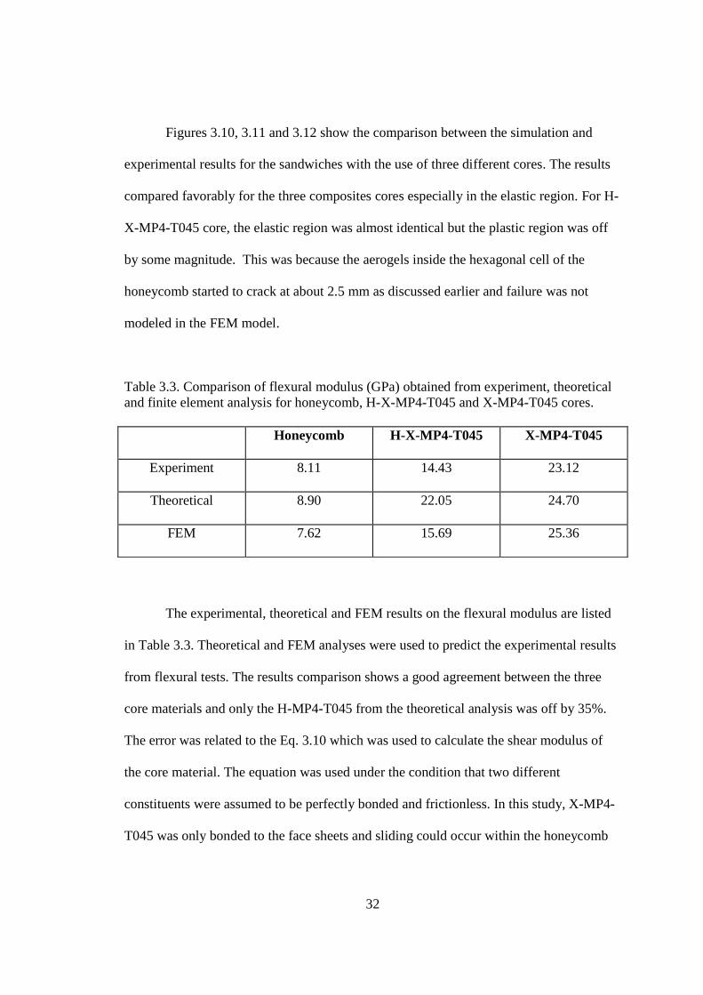
Figure 3.9. Comparison of the load-displacement curve from FEM model and experimental results for honeycomb core.
Flexural Displacement (mm)
Fle
xura
lLoa
d(k
N)
0 2 4 6 80
0.2
0.4
0.6
0.8
ExperimentFEM

31
Figure 3.10. Comparison of the load-displacement curve from FEM model and experimental results for H-X-MP4-T045 core.
Flexural Displacement (mm)
Fle
xura
lLoa
d(k
N)
0 0.5 1 1.5 2 2.5 30
0.5
1
1.5
2
2.5
3
ExperimentFEM
Figure 3.11. Comparison of the load-displacement curve from FEM model and experimental results for X-MP4-T045 core.
Flexural Displacement (mm)
Fle
xura
lLoa
d(k
N)
0 2 4 6 80
0.5
1
1.5
2
ExperimentFEM
32
Figures 3.10, 3.11 and 3.12 show the comparison between the simulation and
experimental results for the sandwiches with the use of three different cores. The results
compared favorably for the three composites cores especially in the elastic region. For H-
X-MP4-T045 core, the elastic region was almost identical but the plastic region was off
by some magnitude. This was because the aerogels inside the hexagonal cell of the
honeycomb started to crack at about 2.5 mm as discussed earlier and failure was not
modeled in the FEM model.
Table 3.3. Comparison of flexural modulus (GPa) obtained from experiment, theoretical and finite element analysis for honeycomb, H-X-MP4-T045 and X-MP4-T045 cores.
Honeycomb H-X-MP4-T045 X-MP4-T045
Experiment 8.11 14.43 23.12
Theoretical 8.90 22.05 24.70
FEM 7.62 15.69 25.36
The experimental, theoretical and FEM results on the flexural modulus are listed
in Table 3.3. Theoretical and FEM analyses were used to predict the experimental results
from flexural tests. The results comparison shows a good agreement between the three
core materials and only the H-MP4-T045 from the theoretical analysis was off by 35%.
The error was related to the Eq. 3.10 which was used to calculate the shear modulus of
the core material. The equation was used under the condition that two different
constituents were assumed to be perfectly bonded and frictionless. In this study, X-MP4-
T045 was only bonded to the face sheets and sliding could occur within the honeycomb

33
cell. This gives an idea to increase the performance of H-X-MP4-T045 by bonding the
crosslinked aerogel with honeycomb.
34
CHAPTER IV
ACOUSTIC CHARACTERIZATION
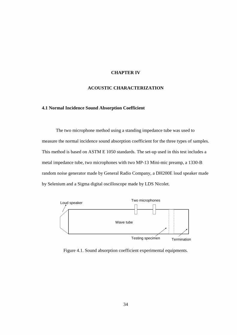
4.1 Normal Incidence Sound Absorption Coefficient The two microphone method using a standing impedance tube was used to
measure the normal incidence sound absorption coefficient for the three types of samples.
This method is based on ASTM E 1050 standards. The set-up used in this test includes a
metal impedance tube, two microphones with two MP-13 Mini-mic preamp, a 1330-B
random noise generator made by General Radio Company, a DH200E loud speaker made
by Selenium and a Sigma digital oscilloscope made by LDS Nicolet.
Two microphones
Loud speaker
Testing specimen
Wave tube
Termination
Figure 4.1. Sound absorption coefficient experimental equipments.
35
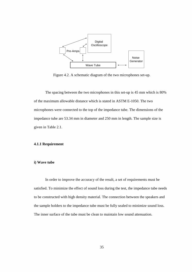
Wave Tube
Noise Generator
Digital Oscilloscope
Pre-Amps
Figure 4.2. A schematic diagram of the two microphones set-up. The spacing between the two microphones in this set-up is 45 mm which is 80%
of the maximum allowable distance which is stated in ASTM E-1050. The two
microphones were connected to the top of the impedance tube. The dimensions of the
impedance tube are 53.34 mm in diameter and 250 mm in length. The sample size is
given in Table 2.1.
4.1.1 Requirement i) Wave tube
In order to improve the accuracy of the result, a set of requirements must be
satisfied. To minimize the effect of sound loss during the test, the impedance tube needs
to be constructed with high density material. The connection between the speakers and
the sample holders to the impedance tube must be fully sealed to minimize sound loss.
The inner surface of the tube must be clean to maintain low sound attenuation.
36
ii) Working Frequency Range
(4.1)
where
f = operating frequency, hertz
fL= lower working frequency of the tube, hertz
fU= upper working frequency of the tube, hertz
Working frequency range depends on the size of the tube and the spacing of the
two microphones. The upper limit frequency is corresponding to the diameter of the
impedance tube to maintain plain wave propagation and the limit is defined as
(4.2)
where
c = speed of sound, ms-1
d = diameter of the tube, m
K = 0.586
For lower limit frequency, it depends on the spacing of the microphone and the
accuracy of the analysis system. A large spacing between the microphones will provide
more accurate data. However, the microphones spacing must be less than half wave
length of interest.
(4.3)
UL fff <<
UU fKcdordKcf // <<
Ufcs 2/<<
37
where
s = microphone spacing, m
The recommended maximum microphone spacing is 80% of the c/2fU.
iii) Sound Source
The recommended test signal is random noise with uniform spectral density
function. Such spectral line spacing of the test signal must be compatible with the
analysis bandwidth. The example of test signal includes pseudo-random noise such as
white noise, pink noise, swept sine, and steeped sine.
4.1.2 Calculation
The speed of sound is calculated at the given temperature in the testing
environment. The value of the speed of sound is defined as
(4.3)
where
c = speed of sound, ms-1
T = temperature in testing environment, °C
The transfer functions are used to calculate the normal incidence sound
absorption coefficient. The transfer function is a complex ratio of the acoustic pressure
Tc += 15.27347.20
38
responses. To avoid any mismatch in the amplitude or phase responses, the calibration
between the two microphones is required. The sample used for calibration must be a
highly absorptive material. This is to minimize the reflection of sound from the sample
back to the microphones. First, the transfer function of the real testing configuration as
HI is measured. Next, the two microphones are interchanged and the transfer function
as HII is measured. The calibration transfer function is calculated as follow
(4.4)
(4.5)
(4.6)
Where H is the transfer function, subscript c is calibration, superscript I is first
configuration, superscript II is the second configuration and Φ is the phase of the
complex transfer function.
The transfer function is calculated by taking the ratio of the cross spectrum
density to the input auto power spectrum density function. The equation is defined as
(4.7)
( ) cjc
IIIc eHHHH
_2/1φ=×=
2/1
×=
IIIc HHH
( )III
c φφφ +=2
1
_
11
12 φjeHG
GH ==
39
where
H = complex microphone calibration factor
Φ = phase of the complex transfer function
G11 = auto spectral density function
G12 = cross spectral density function
The transfer function could also be a complex ratio of the Fourier transform of the
acoustic pressure of the microphone nearest to the second microphone. The measured
transfer function needs to be adjusted with the calibrated transfer function from the
highly absorptive specimen as described above. The correct mismatch in the microphone
responses is defined as
(4.8)
Using the correct mismatch in Eq. 4.8, the final transfer function which was used
to calculate the complex reflection coefficient is describe as
(4.9)
(4.10)
where
R = complex reflection coefficient
_
/ φjc eHHHH ==
)(2 slkjjks
jksRj e
He
eHeRR +
−
−−== φ
cfk /2Π=
40
H = transfer function with mismatch corrected
k = wave number, m-1
l = distance from the test sample to the center of the nearest microphone, m
s = spacing between the microphones, m
f = frequency, s-1
Finally the normal incidence sound absorption coefficient as follows
(4.11)
where
α = sound absorption coefficient
R = complex reflection coefficient
4.1.3 Results and Discussions
Sixteen averages were taken from the two samples for each core materials. To
minimize the environmental noise effect, sound source of 10 db higher than the
environmental noise was used.
21 R−=α
41
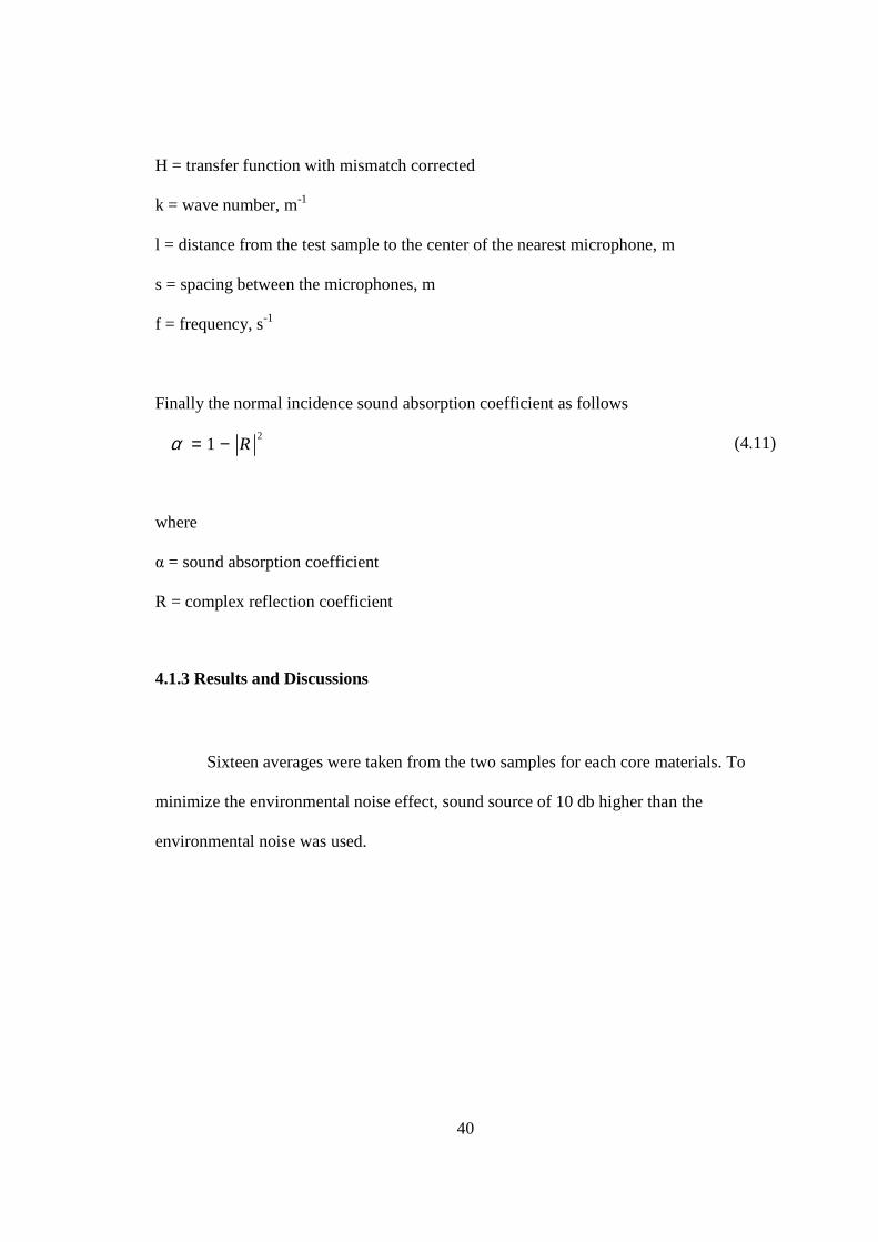
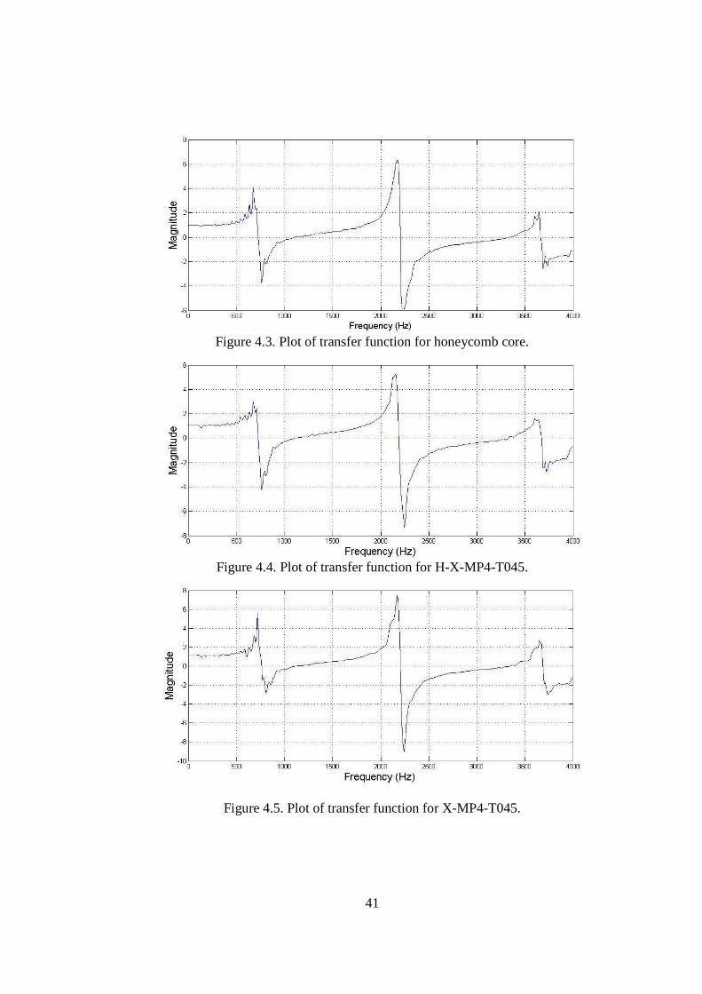
Figure 4.3. Plot of transfer function for honeycomb core.
Figure 4.4. Plot of transfer function for H-X-MP4-T045.
Figure 4.5. Plot of transfer function for X-MP4-T045.
42
Figures 4.3, 4.4 and 4.5 show the transfer function for honeycomb, H-X-MP4-
T045 and X-MP4-T045 cores. The variations between the three plots are not much and
the characteristic of heavier material is higher than lighter material as can be seen. The
order of heavier to lighter sample is X-MP4-T045, H-X-MP4-T045 and honeycomb.
There is some fluctuation in the low frequency range and this indicates that the result is
not accurate at the point. The results might be affected by the vibration from the speaker
to the wave tube, the low frequency environmental noise and also the limitation of the
tube dimension. The accuracy was believed to be in between 315 Hz and 4000 Hz and all
of the results will only be reported in this range.
Frequency (Hz)
Sou
ndA
bsor
ptio
nC
oeff
icie
nt
0
0
1000
1000
2000
2000
3000
3000
4000
4000
0 0
0.2 0.2
0.4 0.4
0.6 0.6
0.8 0.8
1 1
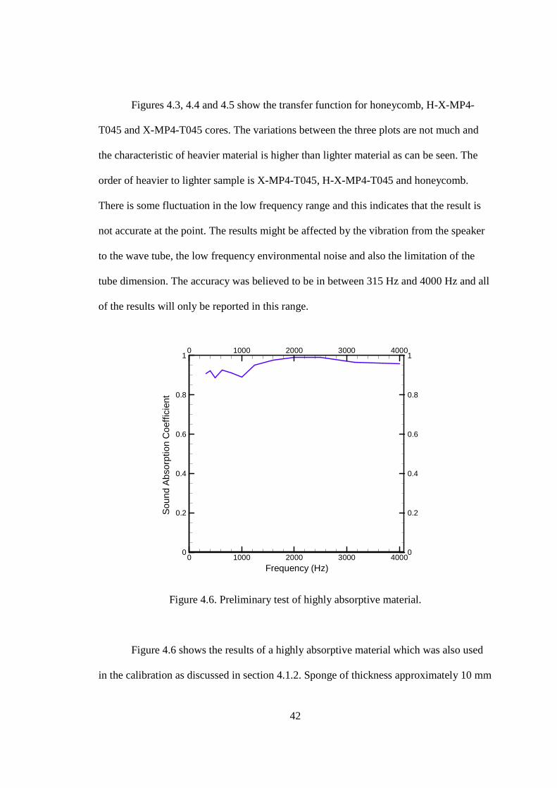
Figure 4.6. Preliminary test of highly absorptive material.
Figure 4.6 shows the results of a highly absorptive material which was also used
in the calibration as discussed in section 4.1.2. Sponge of thickness approximately 10 mm
43
was used as the preliminary sample to test the accuracy of the set-up. The sound
absorption coefficient has a value range from 0 to 1 with 0 representing highly reflective,
and 1 representing highly absorptive. The results agree with the characteristic of the
sponge material very well with the results almost close to 1.
Frequency (Hz)
Sou
ndA
bsor
ptio
nC
oeffi
cien
t
0
0
1000
1000
2000
2000
3000
3000
4000
4000
0 0
0.2 0.2
0.4 0.4
0.6 0.6
0.8 0.8
1 1
Honeycomb
H-X-MP4-T045
X-MP4-T045
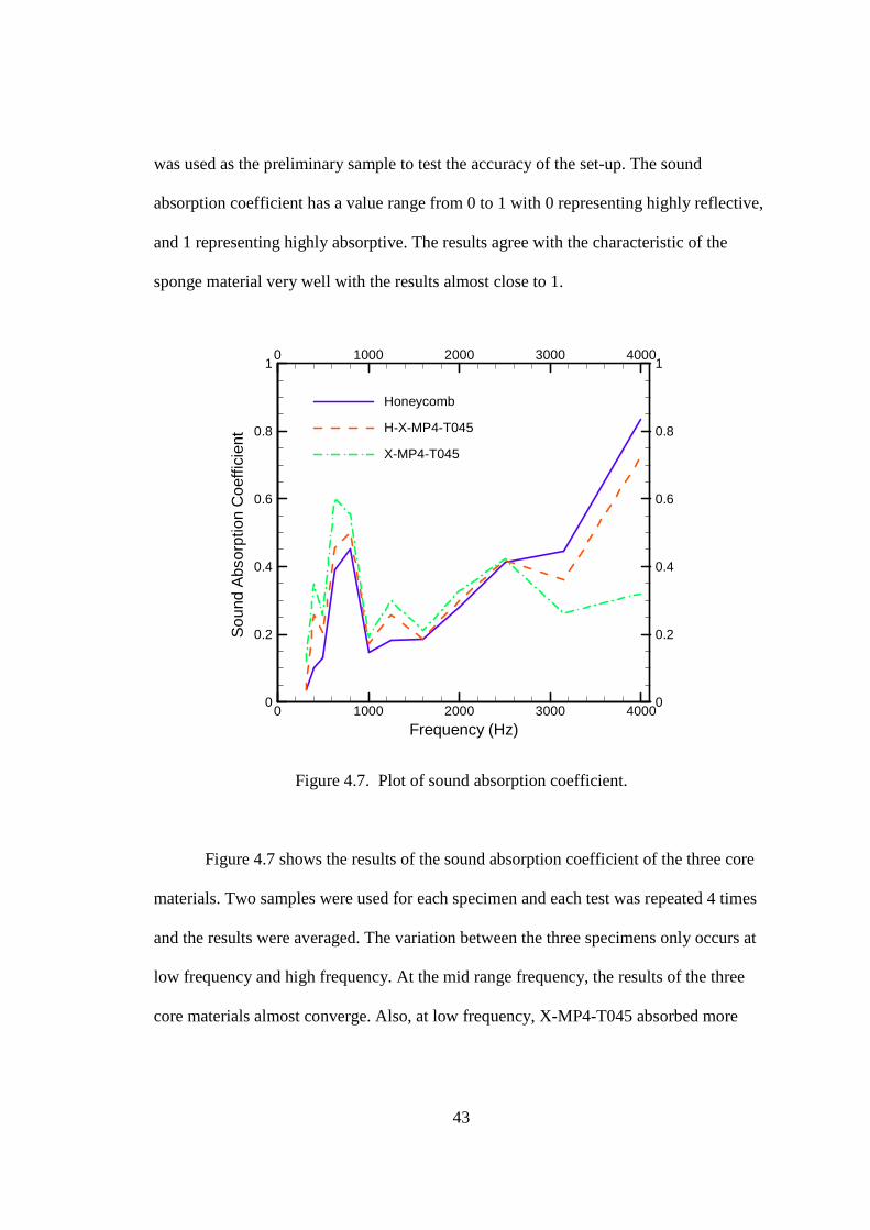
Figure 4.7. Plot of sound absorption coefficient.
Figure 4.7 shows the results of the sound absorption coefficient of the three core
materials. Two samples were used for each specimen and each test was repeated 4 times
and the results were averaged. The variation between the three specimens only occurs at
low frequency and high frequency. At the mid range frequency, the results of the three
core materials almost converge. Also, at low frequency, X-MP4-T045 absorbed more
44
sound than the other two. At higher frequency, honeycomb core performed better than the
X-MP4-T045, and H-X-MP4-T045 was close to honeycomb core.
4.2 Sound Transmission Loss
The measurement of normal incidence transmission loss is the extension of the
measurement of the normal incidence sound absorption coefficient. Almost all testing
standard used to measure sound transmission loss involved a large chamber and a sample
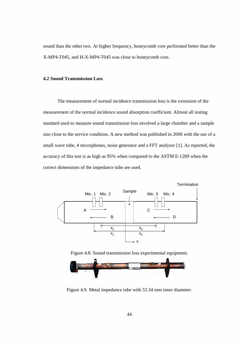
size close to the service condition. A new method was published in 2006 with the use of a
small wave tube, 4 microphones, noise generator and a FFT analyzer [1]. As reported, the
accuracy of this test is as high as 95% when compared to the ASTM E-1289 when the
correct dimensions of the impedance tube are used.
Sample
A
B
C
D
Termination
x
x1
x2 x3
x4
Mic. 1 Mic. 2 Mic. 3 Mic. 4
Figure 4.8. Sound transmission loss experimental equipment.
Figure 4.9. Metal impedance tube with 53.34 mm inner diameter.
45
The length of the impedance used in this test is two times longer than the
impedance tube used to determine sound absorption. Also, two more microphones were
added to the other sides of the impedance tube to detect the acoustic signals after it has
passed through the samples. These signals were used to calculate the normal incidence
transmission loss. The dimension requirement was the same as described in Section 4.1.1
and the set-up includes a noise generator, four pre-amps, a loud speaker and an
oscilloscope which were described in 4.1. The spacing of the microphones was reduced
to 11 mm between microphone 1 and 2 in the first section and microphone 3 and 4 in the
second section of the impedance tube.
4.2.1 Calculations
If the requirement of the distance between the sound source and the first
microphone was met at frequencies below the cutoff frequency, only plane waves can
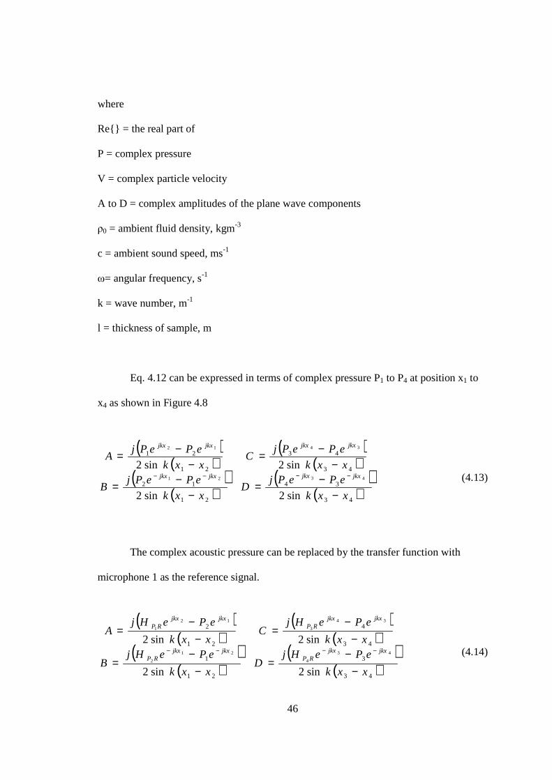
propagate in the tube. In this case, the sound pressure and velocity are described as
follows
(4.12)
( ) ( ){ } ( ) ( )( ){ }( ) ( )( ){ }
≥+≤+
==−
−
lxeeDeC
xeeBeAexPtxp
tjjkxjkx
tjjkxjkxtj
ω
ωω
ωωωωω
Re
0Re,Re,
( ) ( ){ }( ) ( )( )
( ) ( )( )
≥
+
≤
+
== −
−
lxec
eDeC
xec
eBeA
exVtxvtj
jkxjkx
tjjkxjkx
tj
ω
ω
ω
ρωω
ρωω
ω
0
0
Re
0Re
,Re,
46
where
Re{} = the real part of
P = complex pressure
V = complex particle velocity
A to D = complex amplitudes of the plane wave components
ρ0 = ambient fluid density, kgm-3
c = ambient sound speed, ms-1
ω= angular frequency, s-1
k = wave number, m-1
l = thickness of sample, m
Eq. 4.12 can be expressed in terms of complex pressure P1 to P4 at position x1 to
x4 as shown in Figure 4.8
(4.13)
The complex acoustic pressure can be replaced by the transfer function with
microphone 1 as the reference signal.
(4.14)
( )( )
( )( )
( )( )
( )( )43
34
21
12
43
43
21
21
sin2sin2
sin2sin24321
3412
xxk
ePePjD
xxk
ePePjB
xxk
ePePjC
xxk
ePePjA
jkxjkxjkxjkx
jkxjkxjkxjkx
−−=
−−=
−−=
−−=
−−−−
( )( )
( )( )
( )( )
( )( )43
3
21
1
43
4
21
2
sin2sin2
sin2sin243
4
21
2
34
3
12
1
xxk
ePeHjD
xxk
ePeHjB
xxk
ePeHjC
xxk
ePeHjA
jkxjkxRP
jkxjkxRP
jkxjkxRP
jkxjkxRP
−−
=−
−=
−−
=−
−=
−−−−
47
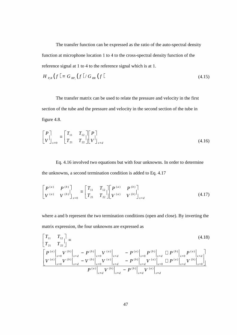
The transfer function can be expressed as the ratio of the auto-spectral density
function at microphone location 1 to 4 to the cross-spectral density function of the
reference signal at 1 to 4 to the reference signal which is at 1.
(4.15)
The transfer matrix can be used to relate the pressure and velocity in the first
section of the tube and the pressure and velocity in the second section of the tube in
figure 4.8.
(4.16)
Eq. 4.16 involved two equations but with four unknowns. In order to determine
the unknowns, a second termination condition is added to Eq. 4.17
(4.17)
where a and b represent the two termination conditions (open and close). By inverting the
matrix expression, the four unknowns are expressed as
(4.18)
( ) ( ) ( )fGfGfH RRRPRP ii/=
dxxV
P
TT
TT
V
P
==
=
2221
1211
0
dx
ba
ba
x
ba
ba
VV
PP
TT
TT
VV
PP
==
=
)()(
)()(
2221
1211
0)()(
)()(
dx
a
dx
b
dx
b
dx
a
x
b
dx
a
x
a
dx
b
dx
a
x
b
dx
b
x
adx
a
x
b
dx
b
x
a
dx
a
x
b
dx
b
x
a
VPVP
VPVPVVVV
PPPPVPVP
TT
TT
====
========
========
−
+−−
+−−
=
)()()()(
0
)()(
0
)()()(
0
)()(
0
)(
)(
0
)()(
0
)()(
0
)()(
0
)(
2221
1211
48
The pressures and the velocities may be expressed in terms of coefficient A to D
from the transfer function.
(4.19)
After substituting Eq. 4.19 into Eq. 4.18, the four unknowns can be used to
calculate the normal incidence sound transmission loss. With a perfectly anechoic
termination which the coefficient D=0, the sound transmission loss is
(4.20)
c
eDeCV
c
BAV
eDeCPBAPjkdsjkds
dx
sss
x
s
jkdsjkds
dx
sss
x
s
0
)()()(
0
)()(
0
)(
)()()()()(
0
)(
,
,,
ρρ−=−=
+=+=−
==
−
==
( )
+++=
2
222100
12114
1log10 TcT
c
TTTL n ρ
ρω
49
4.2.2 Results and Discussion
Frequency (Hz)
Sou
ndT
rans
mis
sion
Loss
(dB
/cm
)
0
0
1000
1000
2000
2000
3000
3000
4000
4000
0 0
5 5
10 10
15 15
20 20
25 25
30 3016 mm plywood
13 mm wallboard
100 mm concrete
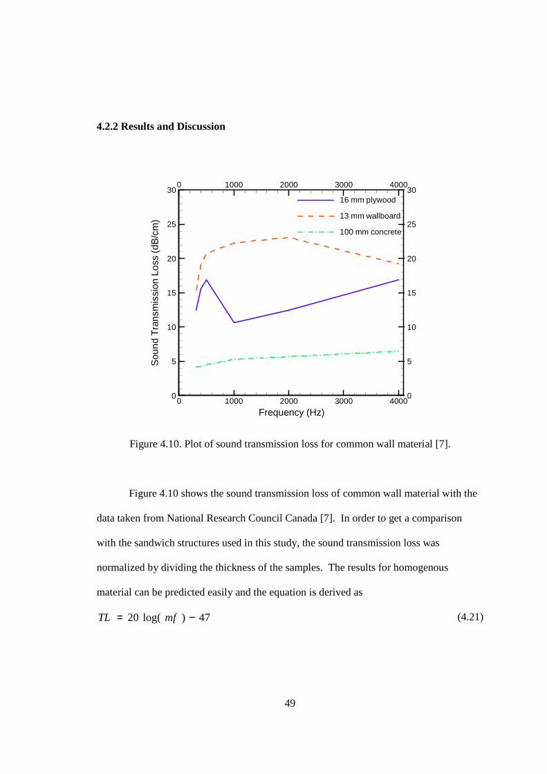
Figure 4.10. Plot of sound transmission loss for common wall material [7].
Figure 4.10 shows the sound transmission loss of common wall material with the
data taken from National Research Council Canada [7]. In order to get a comparison
with the sandwich structures used in this study, the sound transmission loss was
normalized by dividing the thickness of the samples. The results for homogenous
material can be predicted easily and the equation is derived as
(4.21)
47)log(20 −= mfTL
50
where
TL = sound transmission loss, dB
m = mass per unit area, kgm-2
f = frequency, Hz
For non homogenous material such as sandwich structure, the calculation
involved the configuration of all the materials. If designed correctly, the sound
transmission loss can be better than homogenous material and also it gives lower density.
Frequency (Hz)
Sou
ndT
rans
mis
sion
Loss
(dB
/cm
)
0
0
1000
1000
2000
2000
3000
3000
4000
4000
0 0
10 10
20 20
30 30
40 40
50 50
60 60
Honeycomb
H-X-MP4-T045
X-MP4-T045
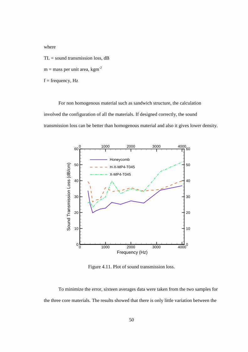
Figure 4.11. Plot of sound transmission loss.
To minimize the error, sixteen averages data were taken from the two samples for
the three core materials. The results showed that there is only little variation between the
51
there core materials at low frequency. However, H-X-MP4-T045 and H-X-MP4-T045
substantially performed better than honeycomb core especially in the range between1000
Hz and 3000 Hz. The results also showed that H-X-MP4-T045 and X-MP4-T045 were
close to each other until 3000 Hz. The X-MP4-T045 core composite gives 12 dB higher
transmission loss at 4000 Hz. X-MP4-T045 and H-X-MP4-T045 composites have higher
sound transmission loss at all the frequency range.
Frequency (Hz)
Sou
ndT
rans
mis
sion
Loss
(dB
/cm
)
0
0
1000
1000
2000
2000
3000
3000
4000
4000
0 0
20 20
40 40
60 60
80 80Honeycomb
H-X-MP4-T045
X-MP4-T045
10 mm
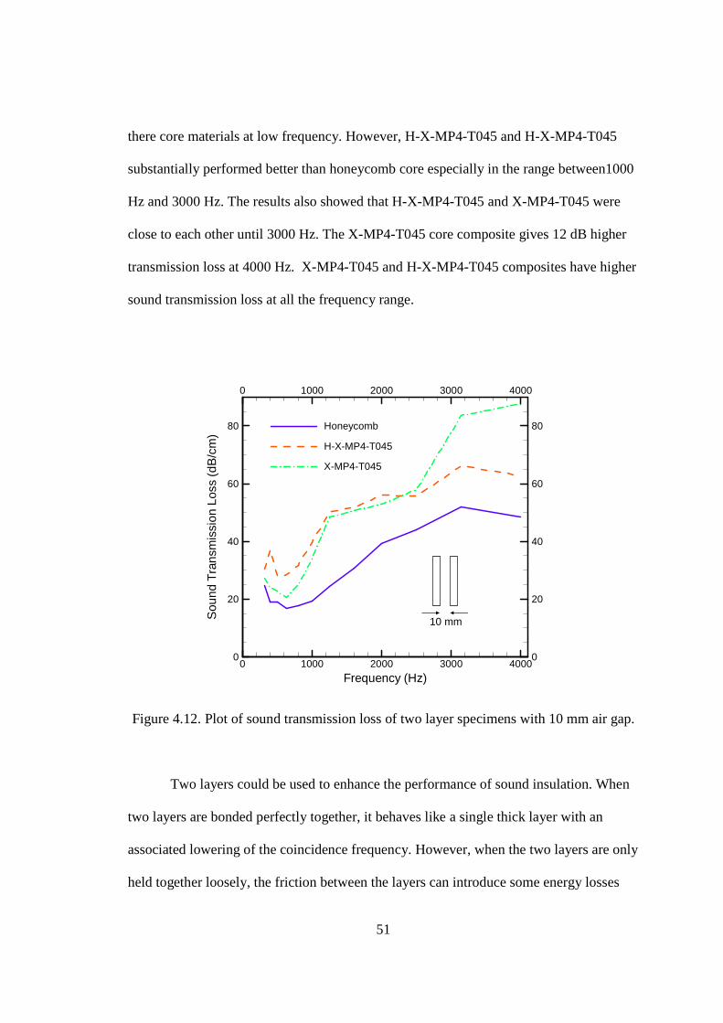
Figure 4.12. Plot of sound transmission loss of two layer specimens with 10 mm air gap.
Two layers could be used to enhance the performance of sound insulation. When
two layers are bonded perfectly together, it behaves like a single thick layer with an
associated lowering of the coincidence frequency. However, when the two layers are only
held together loosely, the friction between the layers can introduce some energy losses
52
[7]. Another idea is to separate the two layers by some distance leaving an air gap or
placing the gap by some absorptive material, if designed correctly, it can highly improve
sound transmission loss [8]. In Figure 4.12, two layers of composites were used, with 10
mm air gap between. As can be seen, the sound transmission loss of the three core
materials was increased by some amount with H-X-MP4-T045 and X-MP4-T045 reached
63 dB and 87 dB at 4000 Hz, respectively.
53
CHAPTER V
CONCLUSION
5.1 Conclusion
Crosslinked aerogel with crosslinker N3200, X-MP4-T045 was fabricated and to
determine their mechanical property and acoustic transmission loss. The crosslinked
aerogel was used as the primary core material and also used to embed into Nomex
Honeycomb for use as core material in a composite sandwich beam. The expectations of
these types of light weight core materials were to provide advantages in mechanical
strength and acoustic insulation.
Three type of core materials were tested follow ASTM D 790 standards. There
core materials are honeycomb, honeycomb embedded crosslinked aerogel, X-MP4-T045
and crosslinked aerogel, X-MP4-T045. It was shown that X-MP4-T045 is excellent in
resisting bending stress and has the highest ultimate strength and flexural modulus.
However, brittle failure mode was occurred at 0.008 flexural strain for X-MP4-T045 core.
For H-X-MP4-T045, the density increased by 35% but the flexural modulus and the
ultimate strength increased by 40% and 46.84%, respectively when compared to the
honeycomb core. The honeycomb core is favor in flexibility but has the lowest flexural
54
strength and modulus. The theoretical and numerical results matched very well
with the experimental results.
The specimens were also tested for the performance of acoustic insulation. The
acoustic tests involved sound absorption coefficient and sound transmission loss both
serve as important criteria of acoustic insulation. It was shown that honeycomb core
absorbed more sound at higher frequency but was little disadvantage at lower frequency.
For sound transmission loss, X-MP4-T045 showed highest performance and the results
for H-X-MP4-T045 was close to X-MP4-T045 except at higher frequency. Two samples
with 10 mm air gap in between were tested and the results were highly enhanced. These
results were compared to commercial wall material using normalization by dividing the
sound transmission loss to the wall thickness. The results showed that X-MP4-T045 and
H-X-MP4-T045 core performed better.
55
CHAPTER VI
FUTURE WORK
The crosslinked aerogel core composites are intended for multifunctional
applications. The following work is suggested for future work.
Thermal Insulation Test
The crosslinked aerogel core composites can be tested to determine their
conductivity. The material can be formulated so that it will combine optimal thermal
conductivity with high mechanical strength and high acoustic damping.
Impact Test
Crosslinked aerogels have been determined to have high energy absorption
capability. Further evaluation is suggested to determine the energy absorption under
dynamic loading. In this area, high velocity impact test can be conducted for a crosslined
aerogel core sandwich structure with the use of three different core materials for
comparison. The drop-weight test is suggested to be conducted with the velocity
measured before and after impact to calculate the energy absorption for comparison.

56
Materials
Different types of crosslinked aerogels can be formulated and to embed into the
Nomex honeycomb core to evaluate its multifunctional performance in comparison with
the previous X-MP4-T045 core. For example, a low density polyurea crosslinked
aerogels have been recently made. Polyurea crosslinked aerogels could become a good
candidate material for further investigation.
57
REFERENCES
[1] O. Olivieri, J. Stuart Bolton, T. Yoo, “Measurement of transmission loss of materials
using a standing wave tube”, INTER-NOISE 2006.
[2] N. Leventis, S. Mulik, X. Wang, A. Dass, V. U. Patil, C. Sotirious-Leventis, H. Lu, G.
Churu, A. Capecelatro, “Polymer nano-encapsulation of templated mesoporous silica
monoliths with improved mechanical properties”, Journal of Non-Crystalline Solids, 354,
632-344, 2008.
[3] G. Zhang, A. Dass, A. M. Rawashdeh, J. Thomas, J. A. Counsil, C. Sotiriou-Leventis,
E. F. Fabrizio, F. I., J. C. Johnson, M. A. Meador, N. Leventis, “Isocyanate-crosslinked
silica aerogel monolith : preparation and characterization”, Journal of Non-Crystalline
Solids, 350, 152-164, 2004.
[4] L. A. Capadona, M. A. B. Meador, A. Alunni, E. F. Fabrizio, P. Vassilaras, N.
Leventis, “Flexible, low density polymer crosslinked silica aerogels”, Polymer 47, 5754-
5761, 2006.
[5] M. Schmidt, F. Schwertfeger, “Applications for silica aerogel products”, Journal of
Non-Crystalline Solids, 225, 364-368, 1998.
[6] Sandwich concept, DIAB sandwich handbook. Available from: www.diabgroup.com.
[7] A.C.C. Warnock. CBD-239 Factors Affecting Sound Transmission Loss. National
Research Council Canada 1985.
58
[8] L. Forest, V. Gibiat, T. Woignier, “Biot’s theory of acoustic propagation in porous
media applied to aerogels and alcogels, Journal of Non-Crystalline Solids 225, 287-
292, 1998.
[9] L. D. Gelb, “Simulating Silica Aerogels with a Coarse-Grained Flexible Model
and Langevin Dynamics”, J. Phys. Chem. C, 111, 15792-15802, 2007.
[10] A.H. Sheikh, P.H. Bull, J.A. Kepler, “Behaviour of multiple composite plates
subjected to ballistic impact”, Composites Science and Technology 69, 704-710, 2009.
[11] N. Gupta, W. Ricci, “Processing and compressive properties of aerogel/epoxy
composites”, Journal of Materials Processing Technology 198, 178-182, 2008.
[12] A. A. Anappara, S. Rajeshkumar, P. Mukundan, P.R.S. Warrier, S.Ghosh, K.G.K.
Warrier, “Impedance spectroscopic studies of sol-gel derived subcritically dried silica
aerogels”, Acta Materialia, 52, 369-375, 2004.
[13] C. Foo, G. Chai, L. Seah, “Mechanical properties of Nomex material and Nomex
honeycomb structure”, Composite Structures, 80, 588-594, 2007.
[14] M. Styles, P. Compston, S. Kalyanasundaram, “The effect of core thickness on the
flexural behaviour of aluminum foam sandwich structures”, Composite Structures, 80,
532-538, 2007.
[15] H. Bart-Smith, J.W. Hutchinson, A.G. Evans, “Measurement and analysis of the
structural performance of cellular metal sandwich construction”, International Journal of
Mechanical Sciences, 43, 1945-1963, 2001.
[16] C. A. Steeves, N. A. Fleck, “ Collapse mechanisms of sandwich beams with
composite faces and a foam core, loaded in three-point bending. Part I: analytical models
59
and minimum weight design”, International Journal of Mechanical Sciences, 46, 561-583,
2004.
[17] M. Styles, P. Compston, S. Kalyanasundaram, “ Finite element modeling of core
thickness effects in aluminum foam/composite sandwich structures under flexural
loading”, Composite Structures, 86, 227-232, 2008.
[18] J. Fricke, 1992. Aerogels and their applications. Journal of Non-Crystalline Solids
147&148 356-362.
[19] L. Gibson, M. Ashby., 1997. Cellular Solids: Structure and Properties, 2nd Edition,
Cambridge University Press.
[20] B. Good., 2006. Computer simulation of fracture in aerogels. In: Material Research
Society Symposium Proceeding.
[21] S. Jones,2006.Aerogel: Space exploration applications. Journal of Sol-Gel Science
and Technology 40, 351-357.
[22] N. Leventis, C. Sotiriou-Leventis, C. Zhang, G. Rawashdeh, 2002. Nanoengineering
strong silica aerogels. Nano letters 2(9) 957-960.
[23] N. Leventis, 2007. Three-dimensional core-shell superstuctures: mechanically strong
aerogels. Accounts of Chemical Research 40 874-884.
[24] N. Leventis, S. Mulik, X. Wang, A. Dass, C. Sotiriou-Leventis, H. Lu, 2007.
Stresses at the interface of micro with nano. Journal of the American Chemical Society
129 10660-10661.
[25] H. Luo, H. Lu, N. Leventis, 2006. The compressive behavior of isocyanate-
crosslinked silica aerogel at high strain rates. Mechanics Time-Dependent Materials 10
83-111.
60
[26] H. Luo, G. Churu, E. Fabrizio, J. Schnobrich, A. Hobbs, A. Dass, S. Mulik, Y.
Zhang, B. Grady, A. Capecelatro, C. Sotiriou-Leventis, H. Lu, N. Leventis, 2008.
Synthesis and Characterization of the Physical. Chemical and Mechanical Properties of
Isocyanate-Crosslinked Vanadia Aerogels. Journal of Sol-Gel Science and Technology
48 113-134.
[27] T. Woigner, J. Phalippou, 1989. Scaling law variation of the mechanical properties
of silica aerogels. Revue De Physique Appliquee C4-179-184.
[28] T. Woignier, J. Pelous, J. Phalippou, R. Vacher, E. Courtens, 1987. Elastic
properties of silica aerogels. Journal of Non-Crystalline Solids 95&96 1197-1202.
61
APPENDICES
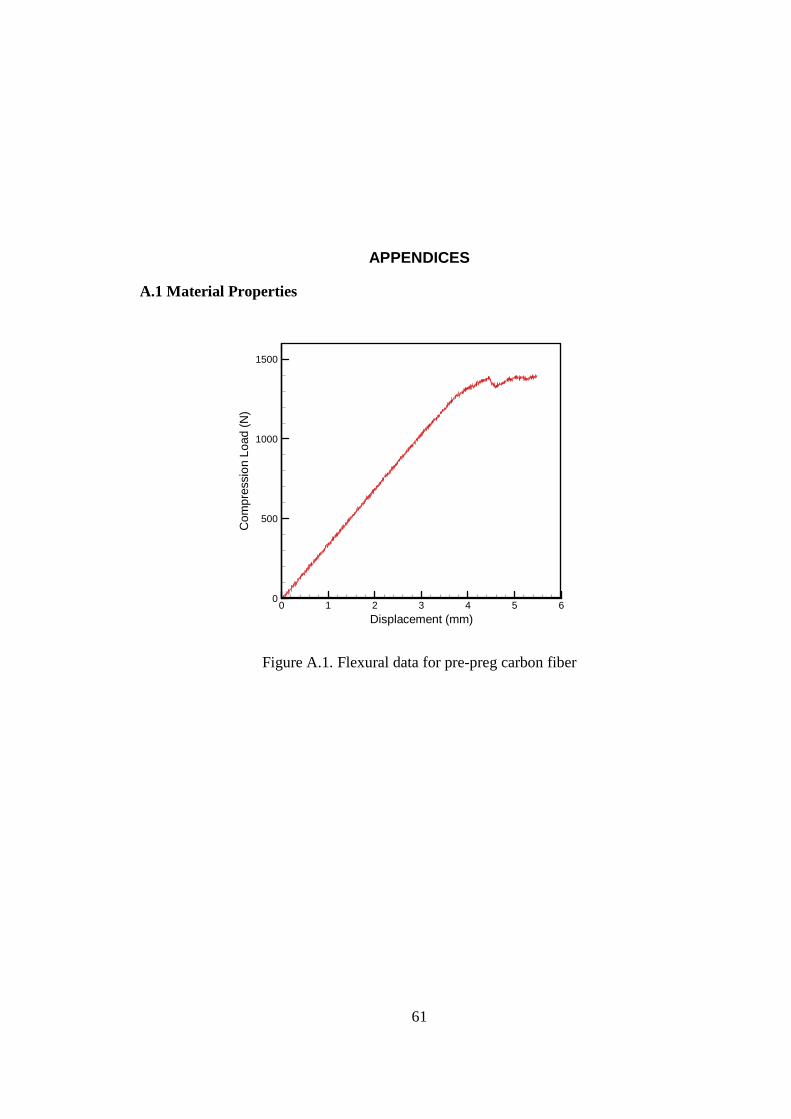
A.1 Material Properties
Displacement (mm)
Com
pres
sion
Load
(N)
0 1 2 3 4 5 60
500
1000
1500
Figure A.1. Flexural data for pre-preg carbon fiber
62
Displacement (mm)
Com
pres
sion
Load
(N)
0 0.2 0.4 0.6 0.8 10
2000
4000
6000
8000
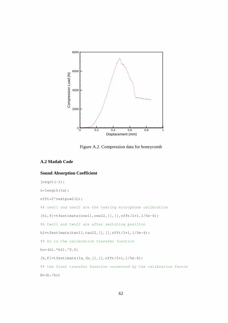
Figure A.2. Compression data for honeycomb
A.2 Matlab Code Sound Absorption Coefficient j=sqrt(-1);
L=length(Ia);
nfft=2^nextpow2(L);
%% one11 and one22 are the testing microphone calibration
[h1,f]=tfestimate(one11,one22,[],[],nfft/2+1,1/5e-6);
%% two11 and two22 are after switching posiiton
h2=tfestimate(two11,two22,[],[],nfft/2+1,1/5e-6);
%% hc is the calibration transfer function
hc=(h1.*h2).^0.5;
[h,F]=tfestimate(Ia,Ib,[],[],nfft/2+1,1/5e-6);
%% the final transfer function corrected by the calibration factor
H=(h./hc)

63
%% calculation of angular frequency
W=2*pi*F/344.989;
%% calculation of sound reflection coefficient
r=((H-exp(-j*W*0.045))./(exp(j*W*0.045)-H)).*(exp(j*2*W*(0.12)));
%% calculation of sound absorption coefficient
alpha=1-(real(r)).^2-(imag(r)).^2;
Sound Transmission Loss %% Ia four microhphone data from first termination condition
%% Ib four microphone data from second termination condition
function Output=TB4(Ia,Ib)
%%Constant value of some input variables
x1=-0.2175;
x2=-0.2065;
x3=0.1775;
x4=0.1885;
d=0.05334;
c=344.989;
R=1.21;
f=1/5e-6;
L=length(Ia(:,1));
nfft=2^nextpow2(L);
%%Calculate the transfer function
for i=1:4
[Ha(:,i),Output(:,1)]=tfestimate(Ia(:,1),Ia(:,i),[],[],nfft/2+1,f);
Hb(:,i)=tfestimate(Ib(:,1),Ib(:,i),[],[],nfft/2+1,f);
64
end
%% Calculate Complex amplitudes of the plane wave components
k=2*pi.*Output(:,1)/c;
Aa=j*(Ha(:,1).*exp(j*k*x2)-Ha(:,2).*exp(j*k.*x1))./(2*(sin(k*(x1-x2))));
Ba=j*(Ha(:,2).*exp(-j*k*x1)-Ha(:,1).*exp(-j*k.*x2))./(2*(sin(k*(x1-
x2))));
Ca=j*(Ha(:,3).*exp(j*k*x4)-Ha(:,4).*exp(j*k*x3))./(2*(sin(k*(x3-x4))));
Da=j*(Ha(:,4).*exp(-j*k*x3)-Ha(:,3).*exp(-j*k*x4))./(2*(sin(k*(x3-
x4))));
Ab=j*(Hb(:,1).*exp(j*k*x2)-Hb(:,2).*exp(j*k*x1))./(2*(sin(k*(x1-x2))));
Bb=j*(Hb(:,2).*exp(-j*k*x1)-Hb(:,1).*exp(-j*k*x2))./(2*(sin(k*(x1-
x2))));
Cb=j*(Hb(:,3).*exp(j*k*x4)-Hb(:,4).*exp(j*k*x3))./(2*(sin(k*(x3-x4))));
Db=j*(Hb(:,4).*exp(-j*k*x3)-Hb(:,3).*exp(-j*k*x4))./(2*(sin(k*(x3-
x4))));
%% Calculate the pressures and particle velocities
Pa0=(Aa+Ba);
Pad=(Ca.*exp(-j*k*d)+Da.*exp(j*k*d));
Va0=((Aa-Ba)/R/c);
Vad=((Ca.*exp(-j*k*d)-Da.*exp(j*k*d))/R/c);
Pb0=(Ab+Bb);
Pbd=(Cb.*exp(-j*k(:,1).*d)+Db.*exp(j*k(:,1).*d));
Vb0=((Ab-Bb)./R./c);
Vbd=((Cb.*exp(-j*k(:,1)*d)-Db.*exp(j*k(:,1)*d))./R./c);
%% Calculate frequency dependent quantities Tij.
65
T11=(Pa0.*Vbd-Pb0.*Vad)./(Pad.*Vbd-Pbd.*Vad);
T12=(-Pa0.*Pbd+Pb0.*Pad)./(Pad.*Vbd-Pbd.*Vad);
T21=(Va0.*Vbd-Vb0.*Vad)./(Pad.*Vbd-Pbd.*Vad);
T22=(-Pbd.*Va0+Pad.*Vb0)./(Pad.*Vbd-Pbd.*Vad);
%% Calculate sound tranmission loss
Output(:,2)=10*log10(0.25*(abs((T11+T12/R/c+R*c*T21+T22)).^2));
end
VITA
KahKit Chan
Candidate for the Degree of
Master of Science Thesis: POLYMER NANOENCAPSULATED SURFACTANT
TEMPLATED AEROGEL CORE COMPOSITES FOR MULTIFUNCTIONAL APPLICATION
Major Field: Mechanical Engineering Biographical:
Personal Data: Born in Ipoh, Malaysia on Feb. 08, 1983, son of SiewChong Chan and YewLian Choong
Education: Received Bachelor of Science degree in Mechanical Engineering from Oklahoma State University in May, 2006. Completed the requirements for the Master of Science in Mechanical Engineering at Oklahoma State University, Stillwater, Oklahoma in July, 2009.
Experience: Research Assistant, 01/2007-present, Polymer Mechanics Laboratory, Oklahoma State University
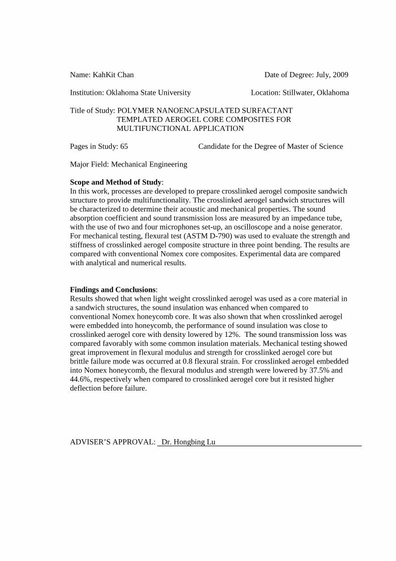
Name: KahKit Chan Date of Degree: July, 2009 Institution: Oklahoma State University Location: Stillwater, Oklahoma Title of Study: POLYMER NANOENCAPSULATED SURFACTANT
TEMPLATED AEROGEL CORE COMPOSITES FOR MULTIFUNCTIONAL APPLICATION
Pages in Study: 65 Candidate for the Degree of Master of Science
Major Field: Mechanical Engineering Scope and Method of Study: In this work, processes are developed to prepare crosslinked aerogel composite sandwich structure to provide multifunctionality. The crosslinked aerogel sandwich structures will be characterized to determine their acoustic and mechanical properties. The sound absorption coefficient and sound transmission loss are measured by an impedance tube, with the use of two and four microphones set-up, an oscilloscope and a noise generator. For mechanical testing, flexural test (ASTM D-790) was used to evaluate the strength and stiffness of crosslinked aerogel composite structure in three point bending. The results are compared with conventional Nomex core composites. Experimental data are compared with analytical and numerical results. Findings and Conclusions: Results showed that when light weight crosslinked aerogel was used as a core material in a sandwich structures, the sound insulation was enhanced when compared to conventional Nomex honeycomb core. It was also shown that when crosslinked aerogel were embedded into honeycomb, the performance of sound insulation was close to crosslinked aerogel core with density lowered by 12%. The sound transmission loss was compared favorably with some common insulation materials. Mechanical testing showed great improvement in flexural modulus and strength for crosslinked aerogel core but brittle failure mode was occurred at 0.8 flexural strain. For crosslinked aerogel embedded into Nomex honeycomb, the flexural modulus and strength were lowered by 37.5% and 44.6%, respectively when compared to crosslinked aerogel core but it resisted higher deflection before failure. ADVISER’S APPROVAL: Dr. Hongbing Lu
Related Documents