Sargent Electrical Services Ltd. 2012 Polyfuse Replacement V6.doc Page 1 of 3 15/8/12 1 Polyfuse Replacement within EC4** and EC500 series PSU’s 1.1 Background A small number of customers may experience a problem with the motorhome step operation, due to a problem with a protective device (a polyfuse, which is an automatic resetting fuse) that provides the over current and entrapment protection for the step. Unfortunately a small number of these protection devices have been found to trip below their rated current. Only motorhomes built between November 2010 and June 2011 maybe affected. The failure manifests itself as the step moves only sporadically, but this should not be confused with the step being jammed or dirty which may produce similar symptoms. So it is important to correctly diagnose the cause of any step problem, and not just assume it is the polyfuse. 1.2 Procedure This procedure uses images from a horizontal mounting EC400 series PSU, but the process is the same for the vertical mounting EC450 PSU or the EC500 series PSU. Remove the PSU from the motorhome. Remove the four front panel fixing screws (two on top, two on the bottom). Gently prise away the front panel from the chassis to gain access to the printed circuit board. The polyfuse is located on the component side of the large circuit board (near the red 4 way connector). It is a buff coloured flat component. Note the polyfuse is located in one position on EC4** series PSU’s and in a different position on the EC500 PSU. To simplify the replacement process we do not de-solder the old polyfuse, we simply cut the ‘legs’ of the polyfuse to remove it. We then refit the new polyfuse to the other side of the circuit board as this is easier to access.

Welcome message from author
This document is posted to help you gain knowledge. Please leave a comment to let me know what you think about it! Share it to your friends and learn new things together.
Transcript
Sargent Electrical Services Ltd. 2012
Polyfuse Replacement V6.doc Page 1 of 3 15/8/12
1 Polyfuse Replacement within EC4** and EC500 series PSU’s
1.1 Background A small number of customers may experience a problem with the motorhome step operation, due to a problem with a protective device (a polyfuse, which is an automatic resetting fuse) that provides the over current and entrapment protection for the step.
Unfortunately a small number of these protection devices have been found to trip below their rated current.
Only motorhomes built between November 2010 and June 2011 maybe affected.
The failure manifests itself as the step moves only sporadically, but this should not be confused with the step being jammed or dirty which may produce similar symptoms. So it is important to correctly diagnose the cause of any step problem, and not just assume it is the polyfuse.
1.2 Procedure This procedure uses images from a horizontal mounting EC400 series PSU, but the process is the same for the vertical mounting EC450 PSU or the EC500 series PSU.
Remove the PSU from the motorhome.
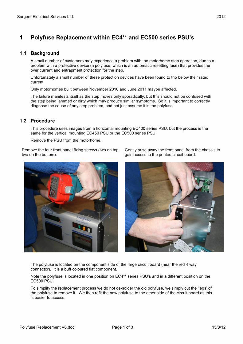
Remove the four front panel fixing screws (two on top, two on the bottom).
Gently prise away the front panel from the chassis to gain access to the printed circuit board.
The polyfuse is located on the component side of the large circuit board (near the red 4 way connector). It is a buff coloured flat component.
Note the polyfuse is located in one position on EC4** series PSU’s and in a different position on the EC500 PSU.
To simplify the replacement process we do not de-solder the old polyfuse, we simply cut the ‘legs’ of the polyfuse to remove it. We then refit the new polyfuse to the other side of the circuit board as this is easier to access.

Sargent Electrical Services Ltd. 2012
Polyfuse Replacement V6.doc Page 2 of 3 15/8/12
EC4 series (EC400 / EC450) EC500
Locate the polyfuse (PCB identification FS16) Locate the polyfuse (PCB identification FS16)
Cut the component legs to remove the polyfuse This photo shows a circuit board built with the new larger polyfuse (so does not need replacing!)
Original (removed) polyfuse which is physically smaller than the replacement part
CUT Here
Sargent Electrical Services Ltd. 2012
Polyfuse Replacement V6.doc Page 3 of 3 15/8/12
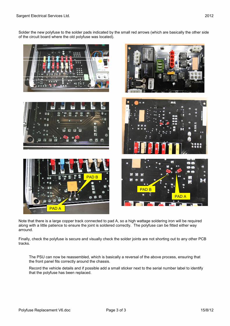
Solder the new polyfuse to the solder pads indicated by the small red arrows (which are basically the other side of the circuit board where the old polyfuse was located).
Note that there is a large copper track connected to pad A, so a high wattage soldering iron will be required along with a little patience to ensure the joint is soldered correctly. The polyfuse can be fitted either way arround.
Finally, check the polyfuse is secure and visually check the solder joints are not shorting out to any other PCB tracks.
The PSU can now be reassembled, which is basically a reversal of the above process, ensuring that the front panel fits correctly around the chassis.
Record the vehicle details and if possible add a small sticker next to the serial number label to identify that the polyfuse has been replaced.
PAD A
PAD B
PAD A
PAD B
Related Documents