38 JOURNAL OF DISPLAY TECHNOLOGY, VOL. 2, NO. 1, MARCH 2006 POLICRYPS Switchable Holographic Grating: A Promising Grating Electro-Optical Pixel for High Resolution Display Application Roberto Caputo, Luciano De Sio, Alessandro Veltri, Cesare Paolo Umeton, and Andrey V. Sukhov Invited Paper Abstract—POLICRYPS, an acronym of POlymer LIquid CRYstal Polymer Slices, is a structure made of perfectly aligned liquid crystal films separated by slices of almost pure polymer. Under suitable experimental and geometrical conditions, the struc- ture is obtained by curing a homogeneous syrup of liquid crystal, monomer and curing agent molecules with a spatially modulated pattern of ultraviolet (UV) radiation. From an optical point of view, POLICRYPS is a holographic diffraction grating with a spa- tial periodicity that can be easily made of sub-micrometric scale, exhibiting diffraction efficiency values as high as 98%. Depending on the used geometry, the POLICRYPS grating can be utilized both in transmission or reflection, with negligible scattering losses, and can be switched ON and OFF by application of an external electric field of the order of few V m. In this paper, we review: 1) the “recipe” to fabricate POLICRYPS holographic gratings, along with their main optical and electro-optical properties; 2) a chemical—diffusive model that, taking into account sample tem- perature and intensity of the curing radiation, indicates the best conditions to fabricate these gratings; 3) a Kogelnik-like model that accounts for the dependence of the diffraction efficiency on material parameters, sample temperature, and applied electric field. Finally, we discuss the possibility of utilizing a micrometric sized POLICRYPS grating as a Grating Electro-Optical Pixel for high resolution display application. Index Terms—High resolution display, holographic grating, liquid crystals. I. INTRODUCTION I N THE LAST few years, great attention has been devoted to the realization of new devices for high resolution display applications or high density data storage, and new approaches have been tried by fabricating micro-opto-electro-mechanical- structures (MOEMS) to be utilized as light intensity switches or modulators. In particular, the Grating Light Valve is a MOEMS device which operate via diffraction rather than by specular reflection, polarization modulation or interferometry [1]. From results reported in literature, it seems that utilization of diffraction gratings can represent a key feature for the realization of high Manuscript received December 5, 2005; revised December 14, 2005. R. Caputo, L. De Sio, A. Veltri, and C. P. Umeton are with LICRYL, Liquid Crystal Laboratory-INFM Unità di Ricerca di Cosenza and Dipartimento di Fisica, Università della Calabria, 87036 Arcavacata di Rende (CS), Italy (e-mail: caputo@fis.unical.it; desio@fis.unical.it; aveltri@fis.unical.it). A. V. Sukhov is with the Institute for Problems in Mechanics, Russian Academy of Science, Moscow 119526, Russia (e-mail: [email protected]). Digital Object Identifier 10.1109/JDT.2005.864156 speed, high resolution digital imaging or high data rate imaging applications [2], [3]. On the other hand, attention has been also paid, recently, to the realization of electrically switchable holographic gratings in liquid crystalline composite materials. It has been shown that devices based on holographic polymer dispersed liquid crystals (HPDLC) are low cost and can exhibit a good diffraction efficiency (DE) [4], [5]. They have, however, some intrinsic drawbacks. In fact, if the droplet size of the nematic liquid crystal (NLC) component inside the polymer matrix is compa- rable to the wavelength of the impinging light, this is strongly scattered; it is necessary, therefore, to reduce the average size of the nematic droplets in order to obtain high diffraction efficiencies and low scattering losses [6]. In this case, however, switching electric fields become rather high. Recently, we have proposed [7], [8] a new kind of holographic grating made of polymer slices alternated to films of regularly aligned NLC; we called it POLICRYPS, an acronym of POlymer LIquid CRYstal Polymer Slices. These structures present a sharp and uniform morphology, without those optical inhomogeneities which are due to the NLC droplets in usual HPDLC samples. In this paper, we review the “recipe” for fabrication of POLICRYPS gratings, along with a characterization of their properties [9], a thermo-diffusive model that explains when and why POLICRYPS or HPDLC gratings are obtained [10], [11], and a Kogelnik-like model for the interpretation of the main features of POLICRYPS [12]. Finally, we illustrate the reasons that induce us to think of the POLICRYPS grating as a good candidate to become a Grating Electro-Optical Pixel for high resolution display application. II. EXPERIMENTAL A. Procedure and Setup The basic idea is to avoid the formation of the nematic phase during the curing process. In this way, an almost complete redis- tribution of NLC and monomer molecules inside the sample is induced, by exploiting the high diffusion which NLC molecules can undergo only when they are in the isotropic state. The standard procedure consists of the following steps: • heating of a syrup of photo-initiator-monomer-NLC mixture up to a temperature which is above the Ne- 1551-319X/$20.00 © 2006 IEEE Authorized licensed use limited to: UNIVERSITA DELLA CALABRIA. Downloaded on January 16, 2010 at 09:15 from IEEE Xplore. Restrictions apply.

Welcome message from author
This document is posted to help you gain knowledge. Please leave a comment to let me know what you think about it! Share it to your friends and learn new things together.
Transcript

38 JOURNAL OF DISPLAY TECHNOLOGY, VOL. 2, NO. 1, MARCH 2006
POLICRYPS Switchable Holographic Grating: APromising Grating Electro-Optical Pixel for High
Resolution Display ApplicationRoberto Caputo, Luciano De Sio, Alessandro Veltri, Cesare Paolo Umeton, and Andrey V. Sukhov
Invited Paper
Abstract—POLICRYPS, an acronym of POlymer LIquidCRYstal Polymer Slices, is a structure made of perfectly alignedliquid crystal films separated by slices of almost pure polymer.Under suitable experimental and geometrical conditions, the struc-ture is obtained by curing a homogeneous syrup of liquid crystal,monomer and curing agent molecules with a spatially modulatedpattern of ultraviolet (UV) radiation. From an optical point ofview, POLICRYPS is a holographic diffraction grating with a spa-tial periodicity that can be easily made of sub-micrometric scale,exhibiting diffraction efficiency values as high as 98%. Dependingon the used geometry, the POLICRYPS grating can be utilizedboth in transmission or reflection, with negligible scattering losses,and can be switched ON and OFF by application of an externalelectric field of the order of few V m. In this paper, we review:1) the “recipe” to fabricate POLICRYPS holographic gratings,along with their main optical and electro-optical properties; 2) achemical—diffusive model that, taking into account sample tem-perature and intensity of the curing radiation, indicates the bestconditions to fabricate these gratings; 3) a Kogelnik-like modelthat accounts for the dependence of the diffraction efficiency onmaterial parameters, sample temperature, and applied electricfield. Finally, we discuss the possibility of utilizing a micrometricsized POLICRYPS grating as a Grating Electro-Optical Pixel forhigh resolution display application.
Index Terms—High resolution display, holographic grating,liquid crystals.
I. INTRODUCTION
I N THE LAST few years, great attention has been devotedto the realization of new devices for high resolution display
applications or high density data storage, and new approacheshave been tried by fabricating micro-opto-electro-mechanical-structures (MOEMS) to be utilized as light intensity switches ormodulators. In particular, the Grating Light Valve is a MOEMSdevice which operate via diffraction rather than by specularreflection, polarization modulation or interferometry [1]. Fromresults reported in literature, it seemsthatutilizationofdiffractiongratings can represent a key feature for the realization of high
Manuscript received December 5, 2005; revised December 14, 2005.R. Caputo, L. De Sio, A. Veltri, and C. P. Umeton are with LICRYL, Liquid
Crystal Laboratory-INFM Unità di Ricerca di Cosenza and Dipartimento diFisica, Università della Calabria, 87036 Arcavacata di Rende (CS), Italy (e-mail:[email protected]; [email protected]; [email protected]).
A. V. Sukhov is with the Institute for Problems in Mechanics, RussianAcademy of Science, Moscow 119526, Russia (e-mail: [email protected]).
Digital Object Identifier 10.1109/JDT.2005.864156
speed, high resolution digital imaging or high data rate imagingapplications [2], [3].
On the other hand, attention has been also paid, recently, tothe realization of electrically switchable holographic gratingsin liquid crystalline composite materials. It has been shown thatdevices based on holographic polymer dispersed liquid crystals(HPDLC) are low cost and can exhibit a good diffractionefficiency (DE) [4], [5]. They have, however, some intrinsicdrawbacks. In fact, if the droplet size of the nematic liquidcrystal (NLC) component inside the polymer matrix is compa-rable to the wavelength of the impinging light, this is stronglyscattered; it is necessary, therefore, to reduce the average sizeof the nematic droplets in order to obtain high diffractionefficiencies and low scattering losses [6]. In this case, however,switching electric fields become rather high. Recently, we haveproposed [7], [8] a new kind of holographic grating made ofpolymer slices alternated to films of regularly aligned NLC; wecalled it POLICRYPS, an acronym of POlymer LIquid CRYstalPolymer Slices. These structures present a sharp and uniformmorphology, without those optical inhomogeneities which aredue to the NLC droplets in usual HPDLC samples.
In this paper, we review the “recipe” for fabrication ofPOLICRYPS gratings, along with a characterization of theirproperties [9], a thermo-diffusive model that explains when andwhy POLICRYPS or HPDLC gratings are obtained [10], [11],and a Kogelnik-like model for the interpretation of the mainfeatures of POLICRYPS [12]. Finally, we illustrate the reasonsthat induce us to think of the POLICRYPS grating as a goodcandidate to become a Grating Electro-Optical Pixel for highresolution display application.
II. EXPERIMENTAL
A. Procedure and Setup
The basic idea is to avoid the formation of the nematic phaseduring the curing process. In this way, an almost complete redis-tribution of NLC and monomer molecules inside the sample isinduced, by exploiting the high diffusion which NLC moleculescan undergo only when they are in the isotropic state.
The standard procedure consists of the following steps:• heating of a syrup of photo-initiator-monomer-NLC
mixture up to a temperature which is above the Ne-
1551-319X/$20.00 © 2006 IEEE
Authorized licensed use limited to: UNIVERSITA DELLA CALABRIA. Downloaded on January 16, 2010 at 09:15 from IEEE Xplore. Restrictions apply.

CAPUTO et al.: POLICRYPS SWITCHABLE HOLOGRAPHIC GRATING 39
Fig. 1. Sketch of the experimental setup. ; ; ; ;; ; ; ;
. (Color version available online at http://ieeexplore.ieee.org.)
matic-Isotropic transition point of the NLC component;this step prevents the appearance of a nematic phaseduring the curing process;
• illumination of the sample with the interference patternof a curing UV radiation;
• slow cooling (down to room temperature) of the samplebelow the Isotropic-Nematic transition point after thatthe curing UV radiation has been switched off and thepolymerization process has come to an end.
The experimental setup used both for the UV curing andthe DE measurements is presented in Fig. 1. A single modebeam from an Ar-Ion laser operating at the wavelength
m is broadened by the beam expander BE upto a diameter of about 25 mm; further, it is divided into twobeams of nearly the same intensity by the beam splitter BS.These two beams intersect at the entrance plane of the samplecell, giving rise to an interference pattern whose spatial perioddepends on the interference angle and can be varied in the range
m. An aperture A (3 mm in diameter) placedbefore the sample entrance provides a uniform intensity of thecuring beam all over the exposed part of the cell. The tempera-ture of the sample is monitored by a thermo-controller. In orderto study the DE dependence on an applied external voltage, wehave utilized a 1-kHz signal from a bipolar modulator, whoseamplitude goes up to 200 V. The morphology of fabricatedgratings is checked by means of a standard Polarization OpticalMicroscope (POM) with a resolution of about 0.5 m.
The DE of gratings is measured by using a He–Ne laserm probe beam of about 100 W power, slightly
focused on the sample in order to obtain a spot diameter ofabout 1 mm; the angle of incidence of the probe beam is chosenin such a way that Bragg condition is satisfied. Both s-typeand p-type polarization of the probe beam can be utilized.Transmitted and first-order diffracted beams are detected bytwo photodiodes (TR and FD), respectively, whose outputsare sent to the data acquisition system. The DE value for eachorder of diffraction is calculated by referring to the initialtransmitted intensity before curing. Before starting the curingprocess of each sample, we measure the intensity of theimpinging probe beam (before the sample) and its transmittedintensity . Then, once the curing process has been completed
and the UV light switched off, we measure the intensityof the zeroth-order (direct transmitted) probe beam and theintensity of the first-order diffracted probe beam. In thisway we get the zeroth-order transmittivity , thefirst-order transmittivity , the total transmittivity
and the first-order DE, which is usuallycalculated as .
B. POLICRYPS versus HPDLC
Fig. 2 shows a comparison between the performances ofa standard, non “small droplet” HPDLC and a POLICRYPSgrating obtained from the same initial syrup, prepared by di-luting the NLC 5CB by Merck ( 30 wt %) in the pre-polymersystem Norland Optical Adhesive NOA-61; the sample cells,made by using ITO—coated glass slabs, were 16 m thick.We have measured the first-order DE at room tempera-ture both for POLICRYPS and HPDLC gratings, obtaining
and . The value ofis not the highest that, in general we are able to
get since, in different POLICRYPS gratings (not used for thiscomparison), values as high as 98% have been measured. AlsoHPDLC gratings can exhibit, in general, better performances[5] than the ones of our sample; here, we stress that we justwant to compare optical and electro-optical properties of aPOLICRYPS and a HPDLC grating obtained from the sameinitial syrup, in the same experimental conditions except for thecuring temperature.
The electro-optic response of the two gratings has beenstudied by exploiting a low frequency (500 Hz) square wavevoltage. Fig. 2(a) represents the switching curve of thePOLICRYPS grating. The behavior of the first-order trans-mittivity (circles), zeroth-order transmittivity (squares)and total transmittivity (triangles) is reported versus ther.m.s. applied electric field. We stress that is only slightlylower than 1 and remains at about the same value in the wholerange of applied fields. This indicates that the grating exhibitsnegligible scattering losses. Results are quite different for theHPDLC grating [see Fig. 2(b)]. Here, the total transmittivitystarts from about 68% and increases as the applied field in-creases, showing that scattering losses are quite high at thebeginning and are reduced by the application of the external
Authorized licensed use limited to: UNIVERSITA DELLA CALABRIA. Downloaded on January 16, 2010 at 09:15 from IEEE Xplore. Restrictions apply.

40 JOURNAL OF DISPLAY TECHNOLOGY, VOL. 2, NO. 1, MARCH 2006
Fig. 2. Electric field dependence of zeroth-order transmittivity (squares),first-order transmittivity (circles) and total transmittivity (triangles) for:(a) POLICRYPS grating and (b) HPDLC grating at room temperature. Error barsare of the order of the dot size. The pictures in the boxes show, respectively, atypical POLICRYPS and HPDLC grating morphology with the same spatialperiod. (Color version available online at http://ieeexplore.ieee.org.)
field which, evidently, by reorienting the NLC director in theHPDLC droplets, matches the polymer index of refraction.The switching efficiency (whereand are the first-order transmittivity in the switch-on andswitch-off condition, respectively) is the same (93.3%) for bothgratings. Where the switching field values are concerned, in theHPDLC the 1st diffracted beam is almost completely switchedoff by a field of about 1.5 V m, while it is needed a value ofabout 4.3 V m to obtain the same effect in the POLICRYPSone. In the present case, this particular difference can be dueto the average droplet size of the HPDLC grating, which is,evidently, large enough to enable low switching fields. This isconfirmed by the measured switching times ( 1.1 msfor POLICRYPS and 10.5 ms for HPDLC, 0.9 msfor POLICRYPS and 1.4 ms for HPDLC). Both rise andfall times of the HPDLC grating are longer than the onesof the POLICRYPS, and this suggests a very large averagesize of HPDLC droplets. The electro-optic behavior shown inFig. 2(a), and its noticeable difference with the one of Fig. 2(b),
represents for us the best evidence that the grating we aredealing with is a POLICRYPS one.
C. Temperature Dependence of POLICRYPS DiffractionEfficiency
Here we report on our first and most investigated POLICRYPSgrating [9]. Sample cells for this characterization were
m thick and have been made by using indium-tin-oxide(ITO)—coated glass slabs. The initial mixture was prepared bydiluting the Nematic Liquid Crystal BL-001 by Merck (con-ventional E7 NLC) in the pre-polymer system Norland OpticalAdhesive NOA-61. The NLC concentration was varied in therange 15% 26% in weight. The temperature of the samplewas varied in the range 23 C–65 C and monitored by a thermostage. Samples have been cured by a total UV intensity of about8 mW/cm , acting for about 17 min. Under POM observation,they reveal a perfect morphology consisting of sharp isotropicpolymer slices separated by nematic films with a uniform align-ment. In Fig. 3, a POM picture is presented which refers to aPOLICRYPS grating with a fringe spacing m, whilea Scanning Electron Microscopy (SEM) picture is also reportedin the same figure for a grating with fringe spacing m.Furthermore, where the long-term stability is concerned, ourPOLICRYPS gratings have revealed no degradation of themorphological features, at least in a period of two years.
The DE has been investigated by using both s-polarized(with electric field ) and p-polarized (with electric field
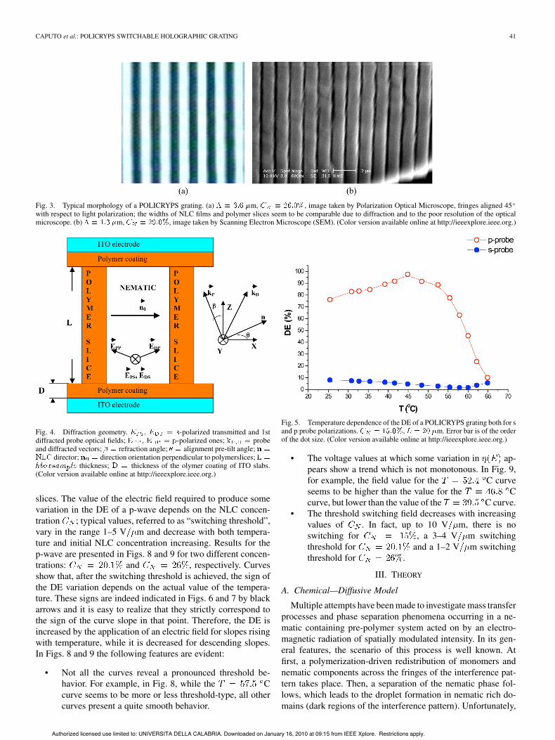
) probe beams, following the geometry presented in Fig. 4.The polarization of the diffracted wave-matched beam [13] inboth cases, strictly corresponded to the one of the probe beam.Typical results are presented in Figs. 5–7 for three differentconcentrations of the E7 NLC in the initial mixture. It is ev-ident that, for the s-polarized probe beam, the DE decreaseswith growing temperature, always exhibiting a minimum at
C– C, while the DE dependence of the p-polarizedprobe beam reveals a quite complex behavior. First of all, it isa non-monotonous function, showing at least one maximum(even two, in the case of high initial NLC concentration), andat least one minimum. As for maximal and minimal values,they are more than 95% and less than 7%, respectively (for lowvalues of the initial NLC concentration). Furthermore, we seethat curves concerning both s and p polarized probe beams al-ways reach a steady-state value for temperatures higher than 58C, which is the nematic-isotropic (N-I) transition temperature
of the NLC in the sample. This fact confirms that in the NLCfilms, between two polymer slices, there is in fact almost pureNLC, whose N-I transition is well known to occur at 61 C (inHPDLC gratings, we had previously observed reductions of15 C–35 C in the value of the N-I transition temperature incomparison with the value for pure NLC [13]).
D. Diffraction Efficiency Dependence on an Applied ElectricField
Up to an amplitude of about 10 V m of the applied elec-tric field, no modification has been observed in the DE of thes-polarized probe beam; this indicates that the s-wave travelsin the sample as an ordinary wave. Therefore the NLC directormust lie in the plane of Fig. 4, perpendicularly to the polymer
Authorized licensed use limited to: UNIVERSITA DELLA CALABRIA. Downloaded on January 16, 2010 at 09:15 from IEEE Xplore. Restrictions apply.
CAPUTO et al.: POLICRYPS SWITCHABLE HOLOGRAPHIC GRATING 41
Fig. 3. Typical morphology of a POLICRYPS grating. (a) m, , image taken by Polarization Optical Microscope, fringes aligned 45with respect to light polarization; the widths of NLC films and polymer slices seem to be comparable due to diffraction and to the poor resolution of the opticalmicroscope. (b) m, , image taken by Scanning Electron Microscope (SEM). (Color version available online at http://ieeexplore.ieee.org.)
Fig. 4. Diffraction geometry. -polarized transmitted and 1stdiffracted probe optical fields; -polarized ones; probeand diffracted vectors; refraction angle; alignment pre-tilt angle;
director; direction orientation perpendicular to polymerslices;thickness; thickness of the olymer coating of ITO slabs.
(Color version available online at http://ieeexplore.ieee.org.)
slices. The value of the electric field required to produce somevariation in the DE of a p-wave depends on the NLC concen-tration ; typical values, referred to as “switching threshold”,vary in the range 1–5 V m and decrease with both tempera-ture and initial NLC concentration increasing. Results for thep-wave are presented in Figs. 8 and 9 for two different concen-trations: and , respectively. Curvesshow that, after the switching threshold is achieved, the sign ofthe DE variation depends on the actual value of the tempera-ture. These signs are indeed indicated in Figs. 6 and 7 by blackarrows and it is easy to realize that they strictly correspond tothe sign of the curve slope in that point. Therefore, the DE isincreased by the application of an electric field for slopes risingwith temperature, while it is decreased for descending slopes.In Figs. 8 and 9 the following features are evident:
• Not all the curves reveal a pronounced threshold be-havior. For example, in Fig. 8, while the Ccurve seems to be more or less threshold-type, all othercurves present a quite smooth behavior.
Fig. 5. Temperature dependence of the DE of a POLICRYPS grating both for sand p probe polarizations. , m. Error bar is of the orderof the dot size. (Color version available online at http://ieeexplore.ieee.org.)
• The voltage values at which some variation in ap-pears show a trend which is not monotonous. In Fig. 9,for example, the field value for the C curveseems to be higher than the value for the Ccurve, but lower than the value of the C curve.
• The threshold switching field decreases with increasingvalues of . In fact, up to 10 V m, there is noswitching for , a 3–4 V m switchingthreshold for and a 1–2 V m switchingthreshold for .
III. THEORY
A. Chemical—Diffusive Model
Multiple attempts have been made to investigate mass transferprocesses and phase separation phenomena occurring in a ne-matic containing pre-polymer system acted on by an electro-magnetic radiation of spatially modulated intensity. In its gen-eral features, the scenario of this process is well known. Atfirst, a polymerization-driven redistribution of monomers andnematic components across the fringes of the interference pat-tern takes place. Then, a separation of the nematic phase fol-lows, which leads to the droplet formation in nematic rich do-mains (dark regions of the interference pattern). Unfortunately,
Authorized licensed use limited to: UNIVERSITA DELLA CALABRIA. Downloaded on January 16, 2010 at 09:15 from IEEE Xplore. Restrictions apply.

42 JOURNAL OF DISPLAY TECHNOLOGY, VOL. 2, NO. 1, MARCH 2006
Fig. 6. Temperature dependence of the DE of a POLICRYPS grating bothfor s and p probe polarizations. , m. The initialdirection of a DE variation under an applied voltage is indicated by blackarrows. Error bar is of the order of the dot size. (Color version available onlineat http://ieeexplore.ieee.org.)
Fig. 7. Temperature dependence of the DE of a POLICRYPS grating bothfor s and p probe polarizations. , m. The initialdirection of a DE variation under an applied voltage is indicated by blackarrows. Error bar is of the order of the dot size. (Color version available onlineat http://ieeexplore.ieee.org.)
diffusion processes in such systems are highly nonlinear andinvolve a sophisticated mathematics. Thus, theoretical modelsusually contain many fitting parameters, which enable a directcomparison of theoretical predictions with experimental resultsbut, somehow, prevent a deeper insight into the real processesthat take place at a microscopic level. Recently, we have pro-posed a model [10] for the interpretation of the mass transferprocesses, which is based on an assumption of mono-function-ality and considers both the chemical and mass transfer pro-cesses that take place during the polymerization effect. Withoutmaking use of any fitting parameter, we have shown that predic-tions of our model explain the main observed features of inves-tigated gratings.
We have assumed that the physical phenomenon driving theNLC redistribution is the conventional Fick diffusion [14], fol-lowing this mechanism.
Fig. 8. Field dependence of the p-probe DE of a POLICRYPS gratingfor different temperature values. , m. Errorbar is of the order of the dot size. (Color version available online athttp://ieeexplore.ieee.org.)
Fig. 9. Field dependence of the p-probe DE of a POLICRYPS gratingfor different temperature values. , m. Errorbar is of the order of the dot size. (Color version available online athttp://ieeexplore.ieee.org.)
i) An interference pattern of curing UV radiation acts on amixture of monomer and NLC molecules, creating im-mobile polymer chains whose length is different passingfrom the bright fringes to the dark ones. We call “pas-sive” the volume occupied by these chains, whilewe call “active” the remaining volume (Fig. 10).Short polymer chains are certainly mobile, but we sup-pose that, after a critical length , chains are immo-bile (the diffusion coefficient depends in a very abruptmanner upon the molecular mass); we introduce such acritical length instead of treating the real dependence ofmobility upon the chain length.
ii) Since NLC molecules are less soluble in cured polymerthan in monomer solution, we assume that, in fact, allNLC molecules will go into the active volume. In thisway, at the sides of the bright fringes, there is a con-centration of NLC molecules higher than in the darkfringes [see Fig. 11(a)]; these molecules will, therefore,
Authorized licensed use limited to: UNIVERSITA DELLA CALABRIA. Downloaded on January 16, 2010 at 09:15 from IEEE Xplore. Restrictions apply.

CAPUTO et al.: POLICRYPS SWITCHABLE HOLOGRAPHIC GRATING 43
Fig. 10. Passive volume formation and molecular diffusion across the fringesof the curing interference pattern.
start to diffuse toward dark fringes; on the other hand,due to the formation of polymer clusters in the centre ofbright fringes, there is, at their sides, a concentration ofmonomer molecules lower than in the dark fringes; thus,these molecules will start to diffuse from dark fringes to-ward the sides of bright fringes. The final concentrationscheme is illustrated in Fig. 11(b).
Let us consider now a thin film of monomer-NLC mixture be-tween two glass slabs parallel to the plane. The mixture is ex-posed to the interference pattern of two laser beams which prop-agate in the plane, symmetrically inclined with respect to the
direction. The curing intensity along the direction is given by
(1)
Here, , where is the fringe spacing, ,with and intensities of the two interfering beams, and
is the visibility of the fringes. Due tothis space-modulated curing action, the rate of polymerizationand the average length of the polymeric chains varies alongand, therefore, also , the concentration of monomer moleculeswhich get polymerized and can be considered immobile, is
-dependent. This spatial modulation of is responsible of themodulation of both nematic concentration and monomerconcentration .
We take into account only those processes which play an im-portant role and make the following assumptions.
• All NLC molecules are extracted from the passivevolume; indicating by their residual concentrationremaining in it, since now on we put .
• All monomer molecules which do not take part in thepolymerization reaction remain in the active volume, bydefinition of the latter.
• All kinetic and diffusion processes take place in the ac-tive volume.
• The spatial redistribution of all components is driven bythe classical Fick diffusion, the stable distribution corre-sponding to a concentration which is uniform in the ac-tive volume.
• Due to their short lifetime, all involved radicals do notdiffuse.
Fig. 11. Distribution of liquid crystal, monomer and polymer molecules.Monomer molecules are denoted by circles, nematic molecules by cylinders,polymer chains by interconnected circles. (Color version available online athttp://ieeexplore.ieee.org.)
• The concentration of photo-initiator remains constantduring the whole reaction, this assumption being justifiedby the fact that is always in excess in every commer-cially available monomer mixture; furthermore, due totheir small size, photo-initiator molecules are easily cap-tured within the passive volume.
• In the calculation of both active and passive volume,the volume occupied by radicals and photo-initiatormolecules can be neglected, their concentrations beingvery low with respect to and .
In this framework, relations between concentrations in the ac-tive volume (indicated with an “ ” apex) and those in the totalvolume during the curing process are
where , and are the number of NLC, monomer andpolymerized monomer molecules respectively, while rep-resents the passive volume. Assuming that monomer and NLCmolecules have almost the same volume , we can write
(2)
Authorized licensed use limited to: UNIVERSITA DELLA CALABRIA. Downloaded on January 16, 2010 at 09:15 from IEEE Xplore. Restrictions apply.

44 JOURNAL OF DISPLAY TECHNOLOGY, VOL. 2, NO. 1, MARCH 2006
where we have taken into account that
Here is the total number of NLC and monomer moleculesand represents the total molecular concentration:
, the “ ” apex referring to the initial condition before poly-merization reactions take place. For them, we use a classicalreaction scheme for radical polymerization [10], [14]
(3)
where the apex (1) indicates that reaction refers to a single mol-ecule.
The process can be divided in three main steps—the initialone, the intermediate or prolongation stage, and the final ortermination stage. The first two equations take into accountthe photo-excitation reaction of a photo-initiator moleculeand the production of a radical molecule . Reactions 3) and4) represent the radical chain growth, by addition of amonomer molecule . Reaction 5) reproduces photo-ini-tiator molecules by two radical reactions, diminishing theconcentration of radicals. Reactions 6) and 7) are terminationswhich give the th-order polymer chain . We neglect chaintransfer, inhibition and cross-linking reactions, and supposethe constants of both prolongation and termination stages areindependent of the length of the involved radical chains, writing
for all for all
Now we can write the balance equations for the concentration ofradicals which take part in the polymerization reaction; we startby taking into account the radical concentration . Increasingof this concentration is due to reactions 1) and 2). Thereforethe rate of is proportional to the intensity W of the incidentradiation and to the photo-initiator concentration through ainitiation constant : . By using 4), 6) and7), we write contributions to the concentration of the genericn-length radical chain . Summing over all terms, we obtaintwo balance equations for steady state concentrations
for
In writing these equations we have supposed that the radicalconcentration remains constant during the process. Taking intoaccount that (the radical chains concentration de-creases by increasing the chain length) and introducing the sumof radical concentrations we sum the equa-tions and get
(4)
The monomer concentration can be obtained in a similar way.Taking into account contributions from systems (3) and (4) for
, we get
(5)
where the apex indicates that this rate is due to the polymer-ization reactions only.
We consider now the diffusion process. Indicating with S asurface perpendicular to the sample walls and parallel to theplane, the flux of molecules diffusing trough S, from a smallvolume , in the direction in the unit time, is given by
where is the Fick diffusion constant. In our case, the passivevolume affects the area trough which diffusion can takeplace, since a section of is a fraction of S; thus the effectivearea available for diffusion is . A similarconsideration holds for concentrations, since only molecules inthe active volume can take part in the diffusion process. Theeffective flux in the unit time through the unit surface is given,therefore, by
The number of particles flowing in the direction in a timeinterval dt can be written as
thus, the rate of monomer concentration due to diffusion pro-cesses is given by
(6)Finally, taking into account both the chemical and the diffusioncontributions, the monomer depletion rate will satisfy the equa-tion
(7)The master equation for the NLC concentration can be ob-
tained in a similar way, taking into account that in this case only
Authorized licensed use limited to: UNIVERSITA DELLA CALABRIA. Downloaded on January 16, 2010 at 09:15 from IEEE Xplore. Restrictions apply.

CAPUTO et al.: POLICRYPS SWITCHABLE HOLOGRAPHIC GRATING 45
diffusion processes are effective, since NLC molecules do notundergo any chemical reaction. Thus
(8)
where, in a first approach, the diffusion coefficient of NLCmolecules is supposed to be the same of monomers. The con-centration Y of monomer molecules polymerized in the passivevolume is given by the summation on N of terms obtainedby multiplying the concentration of the polymer chain oforder N, times its length (starting from the smallest length
that has been assumed to be immobile)
The rate of production of is given by
where the factor 1/2 is needed to avoid double-counting of thedifferent terms. From the rate of we obtain
the ratio of two subsequent radical concentrations being bydefinition. The second equation is obtained from the require-ment that the sum of all gives by definition. Finally, weobtain
(9)
with initial conditions
In order to have a better insight into the features of theoccurring phenomena, we rewrite our main equations ina reduced form by introducing the relative concentrationof components ; ; , andthe dimensionless time and coordinate (where
), . We obtain thesystem
(10)where
with initial conditions
Furthermore, the final steady state distribution of the NLC con-centration , is determined by the final distribution throughthe requirement of a uniform concentration in the active volume
(11)
the normalization integral in (11) enables to find the value of theconstant .
An analytical solution of system (10) can be obtained onlywhen the diffusion process is negligible (the so called “fastcuring regime”) [10] and, in general, a numerical approachis needed [11]. We have utilized a second-order Runge-Kuttascheme for temporal derivatives with a step ,matching the need of stable solutions with an acceptable com-putational time. For spatial derivatives, a central derivativescheme has been used in which, for a given B value, the spa-tial step automatically ensures the stability of solutions. InFig. 12 the main features of our model are reported. The variablewhich determines the DE of gratings, that is the modulationof the polymer concentration across the fringes (calculated asthe first Fourier component of [10]) is plotted as a functionof B and G parameters for . This shows that two regionsof high values (efficient gratings) can be obtained—for
, the polymerization reaction is very fast in comparisonwith diffusion; starting from a uniform distribution of photo-ini-tiators and monomers, the high number of radicals created inthe bright fringes often recombine each other and form a newphoto-initiator molecule before meeting monomers and formpolymer chains. On the other hand, the few radicals createdin the dark fringes can capture a great number of monomersbefore a chain in closed. This corresponds to the case presentedin Fig. 13, where curves of the polymer concentration obtainedfor different values have been obtained by using asinitial monomer concentration and , which representtypical values. The spatial distribution of the curing intensity isalso presented in Fig. 13 for a comparison between the positionof bright fringes and the polymer concentration maxima. In thesame Fig., we report a picture referring to the SEM analysisof a HPDLC grating realized in these experimental conditions;the width of polymer slices well coincides with theoreticalpredictions. In the case with (which means
), it is more probable for a chain to be closed bya radical than to get a new monomer; however, since thereis a great number of available radicals, polymerization takesplace mainly in the bright fringes. The situation is illustratedin Fig. 14, where he agreement with theoretical predictions isevident (also in this Fig. the curing intensity is reportedas a reference). The picture in the frame shows the SEM anal-ysis of a POLICRYPS grating realized in these experimentalconditions. For and there is a high impingingintensity and, in addition, a noticeable diffusion. The curing
Authorized licensed use limited to: UNIVERSITA DELLA CALABRIA. Downloaded on January 16, 2010 at 09:15 from IEEE Xplore. Restrictions apply.

46 JOURNAL OF DISPLAY TECHNOLOGY, VOL. 2, NO. 1, MARCH 2006
Fig. 12. Modulation as a function of parameters B and G.
Fig. 13. Numerical trends of vs for different values, in the condition. The picture in the box shows the SEM picture of a typical HPDLC
grating obtained in the same experimental conditions.
process becomes quite homogeneous yielding no modulationof the polymer concentration. We summarize our results byconcluding that it is possible to recognize two different regimes.The first one (fast curing) is concerned with a polymerizationprocess which is faster than diffusion, so that polymer chainsgrow before monomer diffusion takes place. In the second one(slow curing) the polymerization reaction is quite slow andmonomers can diffuse across the fringes before reacting; in thisregime it is possible to fabricate good holographic gratings,since high values of the concentration modulation can be ob-tained. Diffusion is the main mechanism that determines whichkind of grating (HPDLC or POLICRYPS) will be obtained.In order to produce HPDLC gratings, both low B (low curingintensity) and average G (low temperature) values are needed;it is also known that the production of POLICRYPS gratings
Fig. 14. Numerical trends of vs for different values, in the condition, . The picture in the box shows the SEM picture of a typical
POLICRYPS grating obtained in the same experimental conditions.
needs a high diffusion (high temperature) during the curingprocess (high B and low G values in our model) [7]. Theseconsiderations indicate the two maxima in the surface ofFig. 12 as the curing regimes in which HPDLC or POLICRYPSgratings are realized, respectively.
B. A Kogelnik-Like Model for the Diffraction Efficiency ofPOLICRYPS Gratings
We start by noting that POLICRYPS are, in fact, almost purephase gratings, since no variation in the total (transmitted plusdiffracted) probe intensity has been observed, within 1% ac-curacy, with respect to the initially (before curing) transmittedprobe intensity. Furthermore, our structures are “Bragg” diffrac-tion gratings, because the value of the Bragg parameter [15] is
. This value is low enough to ensure that,
Authorized licensed use limited to: UNIVERSITA DELLA CALABRIA. Downloaded on January 16, 2010 at 09:15 from IEEE Xplore. Restrictions apply.

CAPUTO et al.: POLICRYPS SWITCHABLE HOLOGRAPHIC GRATING 47
Fig. 15. Utilized diffraction geometry for the Kogelnik-like model.; ;
;; ;
; . (Color version availableonline at http://ieeexplore.ieee.org.)
for the nonwave-matched ( first) and second orders (Fig. 15),the DE does not exceed 1.5%.
The conventional Kogelnik [15] approach to this kind of grat-ings gives the following expression for the first-order DE:
(12)
where is the i-th Fourier component of the di-electric permittivity distribution across the fringe and is theangle of refraction of the probe beam inside the sample. The ar-gument depends on the sample thickness L, the probe wave-length and the sample temperature T, (through the nematicpermittivity tensor). Taken from [16], the temperature depen-dence of both components of permittivity and (for opticalfields parallel and perpendicular to the NLC director, respec-tively) is presented in Fig. 16 along with the polymer permit-tivity (data supplied by manufacturer). It is evident that both
and decrease monotonously with temper-ature increase; thus, and depend on T in the same way,and is a monotonously decreasing function of T both for p ands polarization of the probe beam. These simple considerationsexplain all the observed qualitative features, of the DE:
— A minimum in the curve of the s-probe, whichoccurs at the same temperature needed for to equalthe polymer permittivity.
— The observation, in curve of the s-probe, of a mo-notonous decrease with temperature increase. Indeed,an estimation of the room temperature value of givesfor this wave a value that is less than , indicatingthat we are on the first rising slope of the Kogelnikcurve.
— The behavior of the curve of the p-wave, thatpasses through a minimum and then a maximum whengoing from room temperature to the NI transition tem-perature. In this case, indeed, room temperature esti-mation of gives a value higher than , which meansthat, when going from room temperature to the NI tran-sition one, we have to pass both the first decreasing andthe first rising slopes of the Kogelnik curve.
— The coincidence of the local slope of the curvewith the sign of the DE variation induced by applyingan external voltage. Indeed, for a p-probe, this voltage
Fig. 16. Temperature dependence of the dielectric permittivity for purecomponents of the pre-syrup. a) for E7; b) for E7; c) for polymer.(Color version available online at http://ieeexplore.ieee.org.)
induces a decrease of by changing the nematic per-mittivity from to . Therefore we move along theKogelnik curve toward lower values.
From a quantitative point of view, we have implemented amodel [12] in which we write the profile of the dielectric per-mittivity across the fringe (in the direction) as
(13)
where is the grating wave number and stands forthe nth Fourier component of the profile. For the geometryillustrated in Fig. 4, the systems of coupled equations for thenth-order diffracted amplitudes are given by the fol-lowing[17], [18]:
(14)
(15)
Here stands for the probe beam amplitude;where is the light speed in vacuum and the
probe beam angular frequency;is the z-component of the wave vector of the nth wave;
is the mismatch between the probe and the nthwave (see Fig. 16), while is the mismatchbetween the mth and the nth waves. and are respec-tively the x-component and z-components of the probe beamwave vector. The presence of and factors in (15) is
Authorized licensed use limited to: UNIVERSITA DELLA CALABRIA. Downloaded on January 16, 2010 at 09:15 from IEEE Xplore. Restrictions apply.

48 JOURNAL OF DISPLAY TECHNOLOGY, VOL. 2, NO. 1, MARCH 2006
the result of projecting and vectors in the directionof . In our particular case (Fig. 5).Border conditions are and for
, which correspond to the value of the impinging probefield and to the absence of all diffracted waves at the entranceplane of the grating, respectively.
A general analytical solution of systems (14) and (15)does not exist, but in the case of thick (Bragg) gratings, theonly two diffraction terms in the right-hand side of thesesystems which do not contain parameters of the order of
are related to the diffraction of thezeroth-order wave into the first one, and vice versa, thecorresponding values representing the “con-ventional” wave-matching conditions (Fig. 15). Thus, at thezeroth-order approximation of the perturbation theory, we canneglect all values but , obtaining
(16)
(17)
Apexes “O” and “E” have been additionally added to the Fouriercomponents of the permittivity to indicate that they are polariza-tion-dependent. Solution of systems (16) and (17) with abovementioned border conditions gives
(18)
Both solutions are of Kogelnik type. The values of the permit-tivity in (18) have to be calculated for the rectangular fringe pro-file that consists of a uniform nematic film of normalized thick-ness and permittivity , followed by a sliceof polymer of normalized thickness , and permittivity
; the value of can be assumed equal to the nematic volumeconcentration . For such a profile, the Fourier com-ponents of permittivity are
Substituting these values into (18) gives
(19)
Fig. 17. Calculated dependence of DE on temperature for different values.(Color version available online at http://ieeexplore.ieee.org.)
Here while is given by the Fresnel equation
(20)
where is the pre-tilt angle of the director in the plane(Fig. 4).
IV. DISCUSSION
A. Temperature Dependence of the Diffraction Efficiency
Some curves have been obtained by introducingin (19) the experimental values of (Fig. 16), alongwith typical values of the involved physical parameters. Re-sults are presented in Fig. 17 (for different values), for thecase of a p-polarized probe beam; it is evident that the shapeof these curves, as well as the number and position of theirextrema, strongly depend on . Furthermore, maximal andminimal values, which hold 1 and 0, respectively, differ fromthe experimental ones. We have performed a data best fit hasby putting (i.e. homeotropic alignment) in (20) and
, which corresponds also with the value deducedfrom SEM analysis (Fig. 3). Results are reported in Fig. 18,where a second theoretical curve, obtained by putting ,demonstrates the strong dependence of the fit on the value.
Where the extrema values are concerned, we notice that inthese points the Kogelnik formula cannot be applied. A fur-ther perturbation theory iteration carried out for systems (14)and (15) [12], [17] leads to a 2% diffraction efficiency both for
2nd and 1st diffraction orders, which satisfactory matchesthe experimentally observed value. In its turn, a mean deviationof about 4% from extrema values 1 and 0 well fits the experi-mental results.
There is an additional origin of the observed discrepancies.Examining in details the SEM picture of a POLICRYPS grating(Fig. 3), it is evident that the width of the NLC film is notso uniform across the grating, the typical spatial scale of equalvalues being of the order of m (about 1% of the probespot diameter), with a typical variation that we indicate by .Assuming the “ -area distribution function” (normalized to the
Authorized licensed use limited to: UNIVERSITA DELLA CALABRIA. Downloaded on January 16, 2010 at 09:15 from IEEE Xplore. Restrictions apply.

CAPUTO et al.: POLICRYPS SWITCHABLE HOLOGRAPHIC GRATING 49
Fig. 18. Experimental curves of the DE dependence on temperature fittedby putting . The continuous line refers to , 18. (Color versionavailable online at http://ieeexplore.ieee.org.)
total cross section area of the probe beam) as a rectangle ofwidth centred at , , it is more realistic,therefore, to write the DE as
(21)
where
Here we have neglected the weak dependence on of the squareroot in the denominator. Using the condition , wehave expanded at the first order the function of expres-sion (21), obtaining
(22)
This expression reduces to (19) in the case , but fornonzero values of it does not reach the “0” and “1” extremavalues. Fits of the same data of Fig. 18 obtained by using expres-sion (22) are presented in Fig. 19, where we have used(corresponding to ) and the best-fit value . Theagreement is quite good.
B. Dependence of the Diffraction Efficiency on AppliedElectric Fields
The value of the low-frequency dielectric permittivity of thecured polymer, measured separately by a standard capacitancetechnique, is , This is almost equal to the valuemeasured in the E7 NLC, perpendicularly to the director:
; therefore, we can assume that there is a good uniformity ofthe applied low-frequency electric field within the sample. Thethreshold of the Freedericksz transition in each nematic film,
Fig. 19. Theoretical fit of the same data of Fig. 8 performed by using ;. (Color version available online at http://ieeexplore.ieee.org.)
Fig. 20. AC field dependence of the p-probe DE for different temperatures.; m. (Color version available online at
http://ieeexplore.ieee.org.)
that is the “switching threshold”, can be easily calculated usingthe standard variation technique [18]. Taking into account aboveconsiderations on the uniformity of the NLC film, we obtain two(extrema) values
(23)
where is the low-frequency threshold for pure NLC, isthe bend Frank constant and is the low frequency permit-tivity anisotropy of the NLC; for calculations, their tempera-ture dependence are taken from [16]. In Fig. 20, the maximaland minimal values of the threshold field calculated by meansof expression (23) are indicated by arrows in the curve.The points reasonably correspond to the observed values of theswitching threshold.
Authorized licensed use limited to: UNIVERSITA DELLA CALABRIA. Downloaded on January 16, 2010 at 09:15 from IEEE Xplore. Restrictions apply.

50 JOURNAL OF DISPLAY TECHNOLOGY, VOL. 2, NO. 1, MARCH 2006
The switch-off time is [18]
(24)
being the orientational viscosity. Expression (24) yieldsms for typical ps value while, at room temperature,
the measured value of the switch-off time constant isms. There are indications [19] that the difference can be due
to the existence of some weak polymer net in the NLC domain,which increases significantly the orientational viscosity. In ouropinion, the formation of these polymer nets is due to a certainsetup instability during the curing step, and we are trust it canbe avoided by using a “curing mask” instead of an interferencepattern.
C. The POLICRYPS Grating as a Grating Electro OpticalPixel
Utilization of the POLICRYPS switchable diffraction gratingas a Grating Electro Optical Pixel (GEOP) for display applica-tions is a quite promising possibility for the reasons illustratedin the following.
a) There are no mechanical parts and the fringe spacing canbe reduced to about 0.3 m, with a first-order diffractionefficiency as high as 98%. This means that micrometricpixels can be fabricated without affecting the grating fea-tures, with a consequent high resolution of the image
b) The POLICRYPS structure is very versatile and can beused to obtain both transmission and reflection diffrac-tion gratings. All characteristics reported in this paperare related to transmission POLICRYPS gratings, butthe choice of a suitable substrate can enable fabrica-tion of POLICRYPS reflection gratings with almost thesame physical, optical and electro-optical characteristics.Eventually, only a polarizer will be needed to choosewhether an s-wave or a p-wave has to be diffracted.
c) Availability of a satisfactory chemical diffusive modelfor the sample realization enables to choose, for a givenfringe spacing, the best conditions of curing temperatureand UV intensity for realizing a sharp structure with ahigh diffraction efficiency (high value in the B-Gplane).
d) Availability of a satisfactory Kogelnik-like model fordetermination of the diffraction efficiency of the struc-ture enables to choose, for a given fringe spacing, thebest values of sample thickness and material parameters(elastic constant, birefringence etc ) for the realizationof gratings whose optical characteristics remain almostconstant in the whole range of operation temperature.
e) Switching voltages, of the order of few V m are alreadysatisfactory and can be further reduced by choosing NLCmolecules with a high dielectric anisotropy (see (23)).Theoretical switching times, of the order of hundredsof s, can be further reduced by optimizing valuesof NLC viscosity and concentration (see (24); whereconcentration is concerned, it is necessary, however, totake into account an acceptable increase of the switchingvoltage). Experimental values of the switching times canbe brought very close to the theoretical ones by taking
care of the stability of the experimental setup duringthe curing process and by using a mask instead of aninterference pattern.
f) The cost is really low. In addition to the cost of simplematerials like NLC and monomers, also fabrication costsare low. Actually, the choice of fabricating POLICRYPSstructures by exposing the pre-syrup of NLC, monomersand photo-initiators to a UV interference pattern is re-lated to the possibility of changing frequently the gratingperiodicity for research reasons. In applications, oncethe value of has been fixed (following requirementsrelated to the wavelength of impinging light), the curingprocess can be realized by utilization of only one mask.This procedure will also avoid stability problems dueto stochastic vibrations of the interference pattern, thusimproving also the grating quality and reducing theswitching times.
V. CONCLUSIONS
By curing at high temperature a homogeneous mixtureof monomer and NLC with a UV interference pattern ofsuitable intensity, we are able to fabricate a structure, calledPOLICRYPS, in which homogeneously aligned NLC films areseparated by uniform polymer slices. From the optical pointof view, this represents a Bragg diffraction grating whose DEcan be very high, exhibiting also a temperature dependence.Furthermore, the POLICRYPS DE can be switched “ON”and “OFF” by application of an external electric field, whosethreshold value varies in the range of few V m for gratingswith a fringe spacing of the order of the m. A Kogelnik-likemodel which makes use only of real values of physical quan-tities (without the necessity of any fitting parameter) accountsfor the experimental results with a good accuracy. The charac-teristic switching time, which is lower than 1 ms, can be furtherreduced by avoiding the formation of spurious polymer nets innematic domains.
Due to a very low cost, simplicity of fabrication and qualityof features, a POLICRYPS switchable diffraction grating canbecome an innovative and promising Grating Electro OpticalPixel for the realization of high resolution display applications.
REFERENCES
[1] D. M. Bloom, “The grating light valve: revolutionizing display tech-nology,” in Proc. SPIE, vol. 3013, 1997, p. 165.
[2] J. I. Trisnadi, C. B. Carlisle, and R. Monteverde, “Overview and appli-cations of grating light valve based optical write engines for high-speeddigital imaging,” in Photonics West 2004—Micromachining and Micro-fabrication Symp., San Jose, USA, 2004, paper 5348-05.
[3] A. Payne, W. DeGroot, R. Monteverde, and D. Amm, “Enabling highdata-rate imaging applications with grating light valve technology,” inPhotonics West 2004—Micromachining and Microfabrication Symp.,San Jose, USA, 2004, paper 5348-07.
[4] J. D. Margerum, A. M. Lackner, E. Ramos, G. W. Smith, N. A. Vaz, J. L.Kohler, and C. R. Allison, U.S. Patent 5 096 282, month? DAY?, (1992,filed 1990).
[5] R. L. Sutherland, V. P. Tondiglia, L. V. Natarajan, T. J. Bunning, and W.W. Adams, “Electro-optical switching characteristics of volume holo-grams in polymer dispersed liquid crystals,” J. Nonlinear Opt. Phys. Ma-terials, vol. 5, p. 89, 1996.
[6] D. E. Lucchetta, R. Karapinar, A. Manni, and F. Simoni, “Phase-onlymodulation by nanosized polymer-dispersed liquid crystals,” J. Appl.Phys., vol. 91, p. 6060, 2002.
Authorized licensed use limited to: UNIVERSITA DELLA CALABRIA. Downloaded on January 16, 2010 at 09:15 from IEEE Xplore. Restrictions apply.

CAPUTO et al.: POLICRYPS SWITCHABLE HOLOGRAPHIC GRATING 51
[7] R. Caputo, L. De Sio, A. V. Sukhov, A. Veltri, and C. Umeton, “Devel-opment of a new kind of holographic grating made of liquid crystal filmsseparated by slices of polymeric material,” Opt. Lett., vol. 29, p. 1261,2004.
[8] R. Caputo, C. Umeton, A. Veltri, A. V. Sukhov, and N. V. Tabiryan,“Realization o Regular Layered Structures Made of Thin Liquid CrystalFilms Separated by Slices of Polymeric Material (POLICRYPS),” ItalianPatent request TO2003A000 530 of 7/9/2003.
[9] R. Caputo, A. V. Sukhov, C. Umeton, and A. Veltri, “Characterizationof the diffraction efficiency of new holographic gratings with a nematicfilm-polymer slice sequence structure (POLICRYPS),” J. Opt. Soc.Amer. B, vol. 21, p. 1939, 2004.
[10] R. Caputo, A. V. Sukhov, N. V. Tabiryan, C. Umeton, and R. F. Ushakov,“Mass transfer processes induced by inhomogeneous photo-polymeriza-tion in a multycomponent medium,” Chem. Phys., vol. 271, p. 323, 2001.
[11] A. Veltri, R. Caputo, A. V. Sukhov, and C. Umeton, “Model for thephotoinduced formation of diffraction gratings in liquid-crystalline com-posite materials,” Appl. Phys. Lett., vol. 84, p. 3492, 2004.
[12] R. Caputo, A. V. Sukhov, C. Umeton, and A. Veltri, “A Kotgelnik-likemodel for the diffraction efficiency of POLICRYPS gratings,” J. Opt.Soc. Amer. B, vol. 22, p. 735, 2005.
[13] R. Caputo, A. V. Sukhov, C. Umeton, and R. F. Ushakov, “Formation of agrating of submicron nematic layers by photopolymerization of nematic-containing mixtures,” J. Exp. Theor. Phys., vol. 91, pp. 1190–1197, 2000.
[14] P. W. Atkins, Physical Chemistry. Oxford, U.K.: Oxford Univ. Press,1987.
[15] H. Kogelnik, “Coupled wave theory for thick hologram gratings,” BellSyst. Tech. J., vol. 48, pp. 2909–2947, 1969.
[16] B. T. Hallam, C. V. Brown, and J. R. Sambles, “Quantification of thesurface- and bulk-order parameters of a homogeneously aligned nematicliquid crystal using fully leaky guided modes,” J. Appl. Phys., vol. 86,pp. 6682–6689, 1999.
[17] Y. R. Shen, Principles of Nonlinear Optics. New York: Wiley, 1984.[18] P. J. de Gennes, Physics of Liquid Crystals. Oxford, U.K.: Oxford
Univ. Press, 1974.[19] A. Marino, F. Vita, V. Tkachenko, R. Caputo, C. Umeton, A. Veltri, and
G. Abbate, “Dynamical behavior of holographic gratings with a nematicfilm—polymer slice sequence structure,” Euro. Phys. J. E, vol. 15, p. 47,2004.
Roberto Caputo received the Laurea and Ph.D.degrees in physics from the University of Calabria,Rende (CS), Italy, in 2000 and 2005, respectively.
Currently, he is a Marie Curie Fellow at PhilipsResearch, Eindhoven, The Netherlands. His researchinterests include realization of micro and nanodiffractive structures in organic materials, poly-merization driven diffusion processes and dynamictwo-beam coupling in organic materials, organiclasers and discrete diffraction. He is co-holder oftwo patents, including the one on POLICRYPS.
Dr. Caputo received a scholarship from the National Institue for the Physicsof Matter (INFM) in 2000.
Luciano De Sio received the Laurea degree inphysics from the University of Calabria, Rende (CS),Italy, in 2003, where he is currently working towardthe Ph.D. degree in material science, at the LiquidCrystal Laboratory of the same university, in the areaof diffraction gratings in liquid crystalline compositematerials.
He was a Teaching Assistant from 2004 to 2005with the Faculty of Engineering, University of Cal-abria, Italy. His research interests include polymer-ization driven diffusion processes and dynamic two-
beam coupling in organic materials. He is co-holder of a patent on active-feed-back controlled, super-stable optical setup.
Alessandro Veltri received the Laurea degree inphysics and the Doctorate degree in physics from theUniversity of Calabria, Rende (CS), Italy, in 2002and 2005, respectively.
He is currently a post-doctorate fellow at theLiquid Crystal Laboratory of the University of Cal-abria, Rende (CS), Italy. His studies concentrate inadvanced modeling for liquid–crystalline diffractiongratings and numerical methods for solving PartialDifferential Equations (PDE). In this field he takesadvantage of his skills in high level programming in
FORTRAN, C, and C++, realization of C/C++ graphic interfaces and high per-formance parallel computing. He is a co-holder of the patents on POLICRYPSand active- feedback controlled, super stable optical setup.
Cesare Paolo Umeton received the Laurea degree inphysics from the University of Pisa, Italy, in 1974.
Since 1975 he has been Assistant Professor andResearcher of Chemical Physics and, later, AssociateProfessor of Quantum Optics at the University of Cal-abria, Rende (CS), Italy. At present, he is Full Pro-fessor of Experimental Physics at the same university.His research interests have been devoted to atomicand molecular physics, magnetic resonance and op-tics of liquid crystals. In particular, he is currentlyinterested in interaction of liquid crystals with short
laser pulses, spatial solitons in liquid crystal films and diffraction grating for-mation in liquid crystalline composite materials. He is a co-holder of 3 patents,including the one on POLICRYPS, co-editor of the book Novel Optical Mate-rials and Applications (Wiley Interscience, 1997) and co-author of more than80 international journal papers.
Prof. Umeton is President of the Association for Novel Optical Materials andApplications (ANOMA) and Member of the Optical Society of America (OSA).
Andrey V. Sukhov graduated in physics from the Moscow Physical-TechnicalInstitute in 1981. He received the Candidate of Science degree in physics andmathematics from the Institute for Problems in Mechanics, Russian Academy ofScience, Moscow, Russia, in 1984, and the Doctor of Science degree in physicsand mathematics from the Institute of Physics, Ukrainian Academy of Science,Kiev, Ukraine, in 1991.
Since 1981 he worked as Junior Researcher, Staff Researcher, Senior StaffResearcher, and Leading Staff Researcher at the Institute for Problems in Me-chanics, Russian Academy of Science, Moscow, Russia. At present, he is theHead of the same Institute. His studies concentrate in nonlinear optics, op-tical phase conjugation, parametric interactions, stimulated light scattering anddiffraction grating formation in liquid crystalline composite materials. He isco-holder of 2 patents, including the one on POLICRYPS, and is co-author ofmore than 70 international journal papers.
Dr. Sukhov was the invited speaker at OLC’90 and OLC’95, and participatedin several international conferences.
Authorized licensed use limited to: UNIVERSITA DELLA CALABRIA. Downloaded on January 16, 2010 at 09:15 from IEEE Xplore. Restrictions apply.
Related Documents