Pneumatic Valves and Cylinders Get in the

Welcome message from author
This document is posted to help you gain knowledge. Please leave a comment to let me know what you think about it! Share it to your friends and learn new things together.
Transcript

Pneumatic Valvesand Cylinders
Get in the
Colin
Logo w/contact

Get in the
Where Processand ProductConverge to AchieveOptimumResults.
Welcometo the ARO®
Zone.The place where your production processes and our engineered products“converge to achieve optimum results”. Butbeyond process and product there is a thirdessential element that makes the “zone” a veryreal place: the ARO Fluid Power Distributor. Tomake the leap from acceptable to optimum results ittakes in-depth, working knowledge of both process andproduct. Your ARO Fluid Power Distributor knows both,and its this knowledge and expertise, not hype, that willusher you and your operation into this new dimension ofproductivity. The ARO-Zone. . . get into it!
Metal Fab
LightAssembly
Module/Air 2000 Regulator and StackingALPHA Valves control Provenair Cylinders
in a metal fab shop
Provenair and Microair Cylinders used tojoin plastic components.
Colin
Logo1

Fluid Power | 1
SecondaryOperation Wood
workingOperatorSafety
CommercialLaundry
PackagingCommercialLaundry
TubeBending
WoodWorking
FlowControl
Device inserts metal bolts into plasticcomponents
Alpha Valves control cylinders on a bandingmechanism
Two-hand Anti-Tie Down keeps operatorshands clear of clamp and press assembly
operation
Valves on a laundry sorter operate under high ambient heat/humidity conditions Economair Cylinder (enclosed) removesunderweight product from line.
Provenair Cylinders used on a tubebending fixture
Provenair Cylinders advance routers on thisautomated machine
Model FO2 flow control is adjusted tocontrol cylinder retract speed

2 | Numeric Index • Pneumatic Cylinders / Valves
Numeric IndexNumber PageVALVES103-X 64105-X 64109-X 64200 62225-X 63400-X 65401-X 65402-X 65447 65448 65449 65450 6546X-X 66600-X 725030-XX 455040-XX 457000 797006 807007 807008 807010 807012 807102 807103 809600 6713111 4520167 5020172 5020192 6820308-X 6920311-X 6920312-X 6920313-X 6920370 6820467 6820965-X 4920973-X 6620975 6624125 6724130 6724135 6737013 5637112 5659003-842 7659095-X 7759191 7659463-X 7859474-XXX 7859482 7859629 785963X-100 7859632-1 4159634 7859636 7859690-004 7859756-XXX 7859757-XXX 7859759-XX 78
Number Page59760-XX 7859761-XX 7859762-XX 7859764-4 7859765-XXX 7859801 7759802 7759808 7659809 7659836 7759860 7559861 7559903 7859905 7859906 7859908 7859917 75104094 71104096 71104104-XXX 71114054 781141XX-XX 19114772-XX 73115046-XX 73115064-XX 73115422-1 29115455-1 29116153 50116218-XX 73116345-X 41116464 29116572 80116573 79116574 80116575 79116578 79116579 79116647-XX 73116702 79116737 56116738 56116772 78116773 78116737 56116738 56116807 28116808 28116809 28116862-1 29116899-1 29116904-1 29116916-1 29116917-1 29116926-1 29117987 28118154-XX 73118563-X 37118565-X 37118573-XX 37
118597-XXX 79Number Page118598-XXX 7911860X-X 29118612 29118618 29118778 35118785 35118786 35118787 35118790 37118791 3711880X-X 35118818-X 3711882X-X 79118823 79118824 79118843-X 36119209 37119212-XX 79119213 79119219-XXX 37119230 29119231 29119243 45119244 45119245 45119306 29119307-XXX 70119308-XXX 70119309-XXX 70119310-XXX 70119350 14119351 14119352-X 14119353-X 14119354 14119355 14119356 1411936X 13119375 14119376 14119378-XX 73119395 14119397 36119398 37119416 37119422 37119605 65119690-XX 73119698-X 43119714-XX 11119715-XX 11119743 35AXXXXX-XXX-X 27CATXXX-XXX-X 41CBW 73CDN 73CDL-XXX 73CDW 73
CDW-30 73Number PageCHL-XXX 73CHL6-XXX 19CHW 73CHW6 19CHW-30 73CPXX-B 72CSL-XXX 73CSL6-XXX 19CSN 73CSN6 19CSN-30 73EXXXXX-XXX-X 49EV 30-A 67EV 35-A 67EV 125 67EV 250 67EV 375 67FXX-BK 72GMN1X5 36GP1XXX-XXX-X 34GMP1XX-XXX-X 34GSN125 36GSN135 36GX1XXX-XXX-X 79HXXXXX-XXX-X 59KXXXXX-XXX-X 55MKN 28MKP 28M2XXXX 25/64/131M21XXX-XXX-X 20M26M02-XX 21M30M03-XX 21M34M04-XX 21M5XXXX 25M81XXX-XXX-X 17MP3651-2 45MXXMB 25NXX-BK 72PTN 28PEN 28PPN 28PR-10 67RK21X-XX 79S5XXXX 9/11SML51N-XX 9SMH51X-XX 11SML8W-XX 17SSV2XX 127SV10-B 68SV20-B 68CYLINDERS01XX-X0XX-0XX 862XXX-XXXX-XXX 102SXXX-XXX-XXX 89ANXXX-XXXXX-XXX 107SNXXX-XXXXX-XXX 110
Colin
Logo1

Get in the
PneumaticCylinders andAccessories
Developing Specifications
82 | Pneumatic Cylinders
A cylinder’s bore size determines the force it will produce at a givensupply pressure. The weight of the load or the clamping force requiredwill largely determine the force requirements of the cylinder, and hence,the bore size required. But before determining the appropriate bore sizeyou must compensate for air pressure drop, packing friction and loadvariations using the following computation:
A) Compensating for Pressure Drop - Decrease the line pressurevalue by 15 p.s.i. This compensates for pressure drop in thesystem.
Operating pressure (psig) = Line pressure (psig) less 15 (psigpressure drop)
Example: If the line pressure is 95 (psig), subtract 15 (psig) toobtain 80 (psig) operating pressure (for sizingpurposes).
B) Compensating for Packing Friction - Before you begin selecting a cylinder you already know the weight of the load you mustmove or the clamping force you must apply. Multiply this force or load value by 1.25. This compensates for packing friction andload variations. (If speed is of concern for your application, multiply the force value by 2.0.)
Force required (in pounds) = 1.25 x load (or required clamping force)
Example: If cylinder must move 100 pound load, multiplying 100 pounds by 1.25 = 125 pounds force required.
Now, at the top of the chart on page 83, find the column with the operating pressure calculated in “A” above (in this example,80 psig). Go down that column until you find the force requirement calculated in “B”, above (or the next higher value). Notethat the force values in bold type represent the extend force while those in standard type represent retract force (retract force is lowerbecause the rod reduces the effective piston area). Choose the appropriate value, then go to the Cylinder Bore column to findthe bore requirements for your application.
Now that you know the cylinder bore size that will produce the force required for your application, go to page 84 to determine rod sizerequirements.
Air consumption for each cylinder bore size can be found in the chart below.
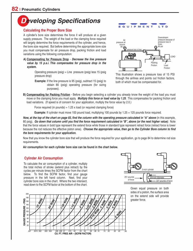
Downstreampressure because ofpressure loss inlines:80 psi
pressure loss in lines
Airpressure at
source.95 psi
LOAD
LoadFriction
PackingFriction
This illustration shows a pressure loss of 15 PSIthrough the airlines and points out friction factors,both of which must be compensated for.
Calculating the Proper Bore Size
Cylinder Air Consumption
2-inch cylinder
5/8-inch diameter
227 pounds of force
251 poundsof force
200
180
160
140
120
100
80
60
40
20
.001 .0015 .002 .003 .004 .006 .008 .01 .015 .02 .03 .04 .06 ..08 .10 .15 .20 .30 .40 ..60
GAU
GE
PRES
SURE
– P
SIG
CU. FT. FREE AIR – (SCFM FACTOR)
1/2" B
ORE
3/4" B
ORE
1-1/8
" BOR
E
1-1/2
" BOR
E2"
BOR
E2-
1/2" B
ORE
3" B
ORE
4" B
ORE
3-1/4"
BORE
5" B
ORE
6" B
ORE
8" B
ORE
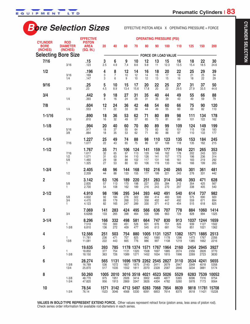
Given equal pressure on bothsides of a piston, the surface areaon the extend side will providegreater force.
To calculate the air consumption of a cylinder, multiplythe total inches of stroke (extend plus retract) by thecycles per minute times the SCFM factor from the chartbelow. To find the SCFM factor, find your gaugepressure in the left hand column. Next, find yourcylinder bore size in the chart. Where the two intersect,read down to fhe SCFM factor at the bottom of the chart.
Colin
Logo1
Bore Selection Sizes
Pneumatic Cylinders | 83
7/16 .15 3 6 9 10 12 13 15 16 18 22 303/16 .123 2.5 4.9 7,4 8.6 9.8 11 12.3 13.5 15.4 18.5 24.6
1/2 .196 4 8 12 14 16 18 20 22 25 29 393/16 .169 3 7 10 12 14 15 17 19 21 25 341/4 .147 3 6 9 10 12 13 15 16 18 22 29
9/16 .25 5 10 15 17 20 22 25 27 31 37 503/16 .23 4.5 8.9 13.4 15.6 17.8 20 22 29.5 27.9 33.5 44.6
3/4 .442 9 18 27 31 35 40 44 49 55 66 881/4 .393 8 16 24 28 31 35 39 43 49 59 79
7/8 .604 12 24 36 42 48 54 60 66 75 90 1201/4 .553 11 22 33 38 44 49 55 60 69 82 110
1-1/16 .890 18 36 53 62 71 80 89 98 111 134 1785/16 .810 16 32 49 57 65 73 81 89 101 122 162
1-1/8 .994 20 40 60 70 80 89 99 109 124 149 1995/16 .917 18 37 55 64 73 83 92 101 115 138 1833/8 .884 18 35 53 62 71 80 88 97 110 133 177
1-1/4 1.227 25 49 74 88 98 110 123 135 153 184 2457/16 1.077 22 43 65 75 86 97 108 118 135 162 215
1-1/2 1.767 35 71 106 124 141 159 177 194 221 265 3537/16 1.617 32 65 97 113 129 146 162 178 202 243 3231/2 1.571 31 63 94 110 126 141 157 173 196 236 3145/8 1.460 29 58 88 102 117 131 146 161 183 219 2921 1.325 27 53 80 93 106 119 133 146 166 199 265
1-3/4 2.405 48 96 144 168 192 216 240 265 301 361 4811/2 2.209 44 88 133 155 177 199 221 243 276 331 442
2 3.142 63 126 189 220 251 283 314 346 393 471 6285/8 2.835 57 113 170 198 227 255 284 312 354 425 5671 2.700 54 108 162 189 216 243 270 297 338 405 540
2-1/2 4.910 98 196 295 344 393 442 491 540 614 737 9825/8 4.602 92 184 276 322 368 414 460 506 575 690 9203/4 4.470 89 179 268 313 358 402 447 492 559 671 8941 4.123 82 165 247 289 330 371 412 454 515 618 825
3 7.069 141 283 424 495 566 636 707 778 884 1060 14143/4 6.6268 133 265 398 464 530 596 663 729 828 994 1325
3-1/4 8.296 166 332 498 581 664 747 830 913 1037 1244 16591 7.510 150 300 451 526 601 676 751 826 939 1127 15021-3/8 6.810 136 272 409 477 545 613 681 749 851 1021 1362
4 12.566 251 503 754 880 1005 1131 1257 1382 1571 1885 25131 11.781 236 471 707 825 942 1060 1178 1296 1473 1767 235613/8 11.081 222 443 665 776 886 997 1108 1219 1385 1662 2216
5 19.635 393 785 1178 1374 1571 1767 1964 2160 2454 2945 39271 18.850 377 754 1131 1320 1508 1697 1885 2074 2356 2828 37701-3/8 18.150 363 726 1089 1271 1452 1634 1815 1996 2269 2723 3630
6 28.274 565 1131 1696 1979 2262 2545 2827 3110 3534 4241 56551-3/8 16.789 536 1072 1607 1875 2143 2411 2679 2947 3349 4018 535813/4 25.870 517 1035 1552 1811 2070 2328 2587 2846 3234 3881 5174
8 50.260 1005 2010 3016 3518 4021 4523 5026 5529 6283 7539 100521-3/8 48.770 975 1951 2926 3414 3902 4489 4877 5365 6096 7316 97541-3/4 47.820 956 1913 2869 3347 3826 4304 4782 5260 5978 7173 9564
10 78.54 1571 3142 4712 5497 6283 7068 7854 8639 9818 11781 157081-3/4 76.14 1523 3046 4568 5330 6091 6853 7614 8375 9518 11421 15228
EFFECTIVE OPERATING PRESSURE (PSI)CYLINDER ROD PISTON
BORE DIAMETER AREA 20 40 60 70 80 90 100 110 125 150 200(INCHES) (INCHES) (SQ. IN.)
EFFECTIVE PISTON AREA X OPERATING PRESSURE = FORCE
Selecting Bore Size FORCE OR LOAD VALUE
VALUES IN BOLD TYPE REPRESENT EXTEND FORCE. Other values represent retract force (piston area, less area of piston rod).Check series order information for available rod diameters in each series.
CYLINDER SELECTION
Colin
Logo1
Rod Diameter
Stop Tube Requirements
84 | Pneumatic Cylinders
Available in Economair & Provenair Only
L-MOUNTS, SIDE- FRONT OR FRONT- CENTER- CLEVIS EYE. ORROD END TAPPED SIDE REAR FLANGE MOUNTED MOUNTED REAR-MOUNTED
CONNECTION END LUGS MOUNTING NUTS TRUNNION TRUNNION TRUNNION
FIXEDAND 0.50 0.50 N/A N/A N/ARIGIDLYGUIDED
PIVOTED AND 0.71 0.71 1.00 1.50 2.00RIGIDLYGUIDED
SUPPORTED,NOT 1.00 1.00 N/A N/A N/ARIGIDLY GUIDED
NOTE: When a stop tube is needed, a minimum 2” length is required on all Economair cylinders with Lippackings, and in 4”, 5”, 6” and 8” Provenair cylinders.
CYLINDER RIGIDLY MOUNTED CYLINDER PIVOT MOUNTED
STROKE FACTOR
NOTE: Remember, long ,slim piston rods may buckle when subjected to a heavy push load.
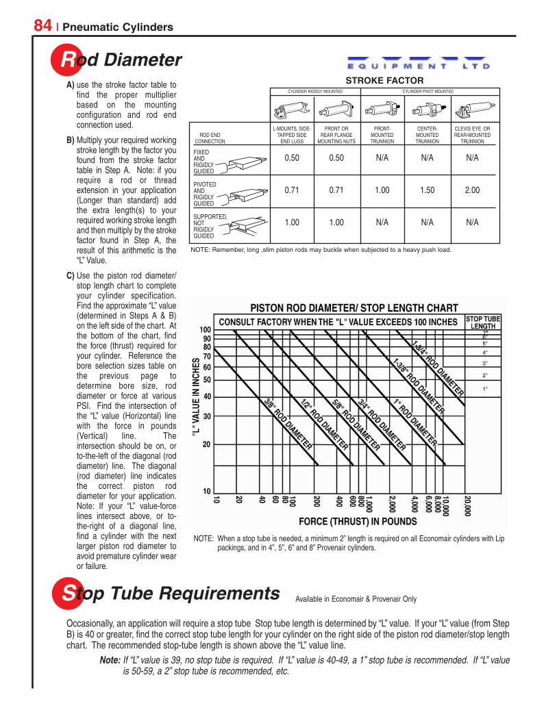
A) use the stroke factor table tofind the proper multiplierbased on the mountingconfiguration and rod endconnection used.
B) Multiply your required workingstroke length by the factor youfound from the stroke factortable in Step A. Note: if yourequire a rod or threadextension in your application(Longer than standard) addthe extra length(s) to yourrequired working stroke lengthand then multiply by the strokefactor found in Step A, theresult of this arithmetic is the“L” Value.
C) Use the piston rod diameter/stop length chart to completeyour cylinder specification.Find the approximate “L” value(determined in Steps A & B)on the left side of the chart. Atthe bottom of the chart, findthe force (thrust) required foryour cylinder. Reference thebore selection sizes table onthe previous page todetermine bore size, roddiameter or force at variousPSI. Find the intersection ofthe “L” value (Horizontal) linewith the force in pounds(Vertical) line. Theintersection should be on, orto-the-left of the diagonal (roddiameter) line. The diagonal(rod diameter) line indicatesthe correct piston roddiameter for your application.Note: If your “L” value-forcelines intersect above, or to-the-right of a diagonal line,find a cylinder with the nextlarger piston rod diameter toavoid premature cylinder wearor failure.
Occasionally, an application will require a stop tube Stop tube length is determined by “L” value. If your “L” value (from StepB) is 40 or greater, find the correct stop tube length for your cylinder on the right side of the piston rod diameter/stop lengthchart. The recommended stop-tube length is shown above the “L” value line.
Note: If “L” value is 39, no stop tube is required. If “L” value is 40-49, a 1” stop tube is recommended. If “L” valueis 50-59, a 2” stop tube is recommended, etc.
Colin
Logo1
Options
Pneumatic Cylinders | 85
Packing Characteristics
Additional options required will help determine which cylinder series will be selected:
Stainless steel piston rods are beneficial in corrosive environments. Stainless steel rods are standard on Micro-Air andSilverair Series. Stainless Steel rods are options on Economair and Provenair Series.
Cylinder cushions are designed to reduce the shock experienced at the end of the stroke by reducing piston speed the last fractionof an inch of stroke. Cylinder cushions are available in Economair and Provenair Series, only.
Packing shape and material affect cylinder performance:
• O-Ring packings are good, general purpose packings, but they require more breakaway force than other packing shapes.
• O-Ring - Low Friction packings provide the effective sealing characteristics of Buna N with the low friction characteristics ofTeflon®. This design is effective where the cylinder must operate at low pressures.
• U-Cup packings offer low breakaway friction and better sealing characteristics at low pressure than O-Ring packings. U-cupsare wear compensating seals; they offer longer wear life than O-rings.
• U-Cup - Self Lube (“Slippery Seals”) packings are ideal in applications where air line lubrication cannot be used. This packingdesign helps reduce cylinder “chatter” in low pressure applications and it offers the same sealing characteristics as Buna N.
Teflon® and Viton® are registered trademarks of the E.I. DuPont Company.
SEALING FRICTION TEMPERATUREMATERIAL CHARACTERISTICS CHARACTERISTICS TOLERANCE AVAILABILITY
O-RING Teflon over Good Medium 0° to 180° F EconomairBuna N O-Ring Seal
O-RING Buna N Good High 0° to 180° F Micro-Air, Economair
O-RING Viton® Good High Up to 300° F Micro-Air, Economair
U-CUP- Nitrile Very Good Low 0° to 180° F Economair, ProvenairSELF-LUBE(“Slippery Seals”)
U-CUP Buna N Very Good Medium 0° to 180° F Economair, Provenair
U-CUP Viton Very Good Medium Up to 300° F Economair, Provenair
NOTE: When applying rod cylinders, there must be no side load or bending stress at any point along the rod. Applications which induceside load and/or bending stress will damage packings, bushings, piston barrels, piston rods and cushion bosses. When metal parts aredamaged, seal and packing replacement is an inadequate repair. The elastomers will quickly become damaged. Inspect and replace allworn or damaged parts when rebuilding cylinders.
Get in the
CYLINDER SELECTION
Colin
Logo1

Features
86 | Micro-Air • Pneumatic Cylinders
Micro-Air Cylinders are ideal for small part positioning, clamping and ejecting. Also they’re the perfectchoice for applications where small bore, medium duty, repairable cylinders are preferred. Prelubed,they’re suitable for operations without externally applied lubrication.
• Micro-Air Cylinders are repairable. Service kits are available to extend the useable life of the cylinder.
• Micro-Air Cylinders operate on air pressure to 200 p.s.i. (14 bar). A tough little cylinder that canhandle the pressures!
• Superior performance over a wide temperature range – 0° to 180° F (-18° to 82° C), even to 300° F(149° C) when Viton seals are used (consult factory).
• Micro-Air Cylinders have superior wear characteristics, thanks to the hard coated aluminum tubingI.D. In addition to an internal hardness of 60 Rockwell C, the barrel has an internal finish of 16microinches or better.
• Micro-Air Cylinders are equipped with Series 303 stainless steel piston rods for corrosion resistance.Also, the ground and polished finish on the rods minimizes friction, providing longer packing life.
• Micro-Air Cylinders provide greater durability than disposable cylinders.
Bore Sizes: 1/2”, 3/4”, and 1-1/8”
Maximum Output Force: 199 pounds (1-1/8” bore)
Standard Operating Temperature range: 0° to 180° F (-18° to 82° C)
Viton Seals Models: For high heat applications. Consult factory.
Range of mounting styles and attachable mounts/ accessories to meet nearly any applicationrequirement.
Series 01
Performance Specifications
Ordering01 XX - X0 XX - 0 XX
STROKE LENGTHWHOLE INCHES FRACTIONS
0 = 0 in 0 = None1 = 1 in 1 = 1/8 in2 = 2 in 2 = 1/4 in3 = 3 in 3 = 3/8 in4 = 4 in 4 = 1/2 in5 = 5 in 5 = 5/8 in6 = 6 in 6 = 3/4 in
7 = 7/8 in
CYLINDER TYPE10 Double Acting, Double End Mount - use with 09 or 19 Mounting Styles50 Double Acting, Nose Mount - use with 29 Mounting Style
BORE SIZE51 1/2 in76 3/4 in.18 1-1/8 in.
Maximum stroke length - 6-7/8-inches.Consult factory for the other strokerequirements.
NOTE: Highlighted selections denote most popular models.
(1/2” Increments, 1/2” through 6”)
To order a cylinder with Viton seals, consult the factory.
MOUNTING STYLE09 Basic - No Mounts - use with Type 10 Double Acting, Double End Mount Cylinder19 Rear Pivot Mount - use with Type 10 Double Acting, Double End Mount Cylinder29 Rear Port - use with Type 50 Double Acting, Nose Mount Cylinder
Mounts must be ordered separately. See page 87.
Colin
Logo1

Ordering
Micro-Air • Pneumatic Cylinders | 87
Dimensional DataSeries 01
Mounting Kit
.199 Dia. Mounting Hole, 2 Pl.
.688 Dia. Hole
1.375
.875
.375
.750
1.250
.875
.125
.625.125
L-Mount
.875
.078
.656
.688 Sq.
1.375 Sq.
.688 Dia. Hole
.199 Dia. Mounting Hole, 4 Pl
1.750 Sq.
Rod Clevis & Clevis Bracket
1.125
1.125
.875
.625 .6875
.813
.125
.199 Dia Mounting Hole, 2 Pl.
.250 Dia. Hole
.125.50 .625
1.031
.25.25
.25
.50
.25 Dia. Pin
1/2” and 3/4” Bore: 1/4-281-1/8” Bore: 5/16-18
Front Flange Rear Flange Mounting Nut.25
5/8-18 Thread
3/4 Hex
Trunnion
DE
A
F
G
HJ
H
J
A
B
C
A/2
A 1.50 1.50 2.25B .625 .625 .875C Dia. .703 .953 1.391D .500 .500 .750E .250 .250 .375F Dia. – – .563G Dia. ± .002 .250 .250 .437H ± .010 .250 .250 .438J – – .0625
Cylinder Bore (Inches)Reference 1/2 3/4 1-1/8
Trunnion Dimensions
* 20561 Trunnion Bracket Kit (right andleft brackets) is used for 20522 and20523 Trunnions. Reference Clevisbracket dimensions.
Cylinder Bore (Inches)1/2 3/4 1-1/8
L-MOUNTS (2 Qty) * 20515 20515 20515
FLANGE MOUNT * 20516 20516 20516
MOUNTING NUT (2 Qty) 20514 20514 20514
CLEVIS BRACKET 20519 20519 20519
TRUNNION 20522 20523 20524
TRUNNION BRACKETS 20561 20561 –
ROD CLEVIS 20517 20517 20518
* NOTE: Mounting nuts included.
MICRO
-AIRCYLINDERS
Colin
Logo1
Get in the
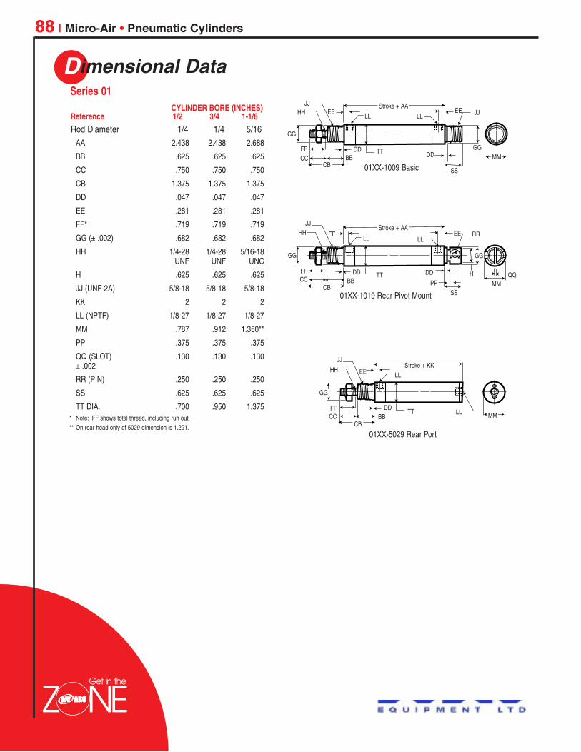
Dimensional Data
88 | Micro-Air • Pneumatic Cylinders
AA 2.438 2.438 2.688
BB .625 .625 .625
CC .750 .750 .750
CB 1.375 1.375 1.375
DD .047 .047 .047
EE .281 .281 .281
FF* .719 .719 .719
GG (± .002) .682 .682 .682
HH 1/4-28 1/4-28 5/16-18.UNF .UNF .UNC
H .625 .625 .625
JJ (UNF-2A) 5/8-18 5/8-18 5/8-18
KK 2 2 2
LL (NPTF) 1/8-27 1/8-27 1/8-27
MM .787 .912 1.350**
PP .375 .375 .375
QQ (SLOT) .130 .130 .130± .002
RR (PIN) .250 .250 .250
SS .625 .625 .625
TT DIA. .700 .950 1.375* Note: FF shows total thread, including run out.** On rear head only of 5029 dimension is 1.291.
Rod Diameter 1/4 1/4 5/16
01XX-1009 Basic
01XX-1019 Rear Pivot Mount
01XX-5029 Rear Port
Stroke + AA
Stroke + AA
JJ
JJ
HH
HH
GG
GG
FF
FF
CC
CC
CB
CB
BB
BB
DD
DD DD
PP
TT
TT
EE
EE
EE
EE
LL
LL
JJ
RR
GG
GG
H
DD
SS
SS
MM
MMQQ
LL
LL
Stroke + KKJJ
HH
GG
FFCC
CB
TTDD
EE
LL MM
LL
BB
Series 01CYLINDER BORE (INCHES)
Reference 1/2 3/4 1-1/8
Colin
Logo1

Silverair™ • Pneumatic Cylinders | 89
Features
Silverair round cylinders are designed for application in OEM and MRO applications wherea disposable, light duty cylinder is preferred. Prelubed, they’re suitable for operationswithout externally applied lubrication. Constructed of stainless steel and aluminum, theystand up to the attack of corrosive environments.
• Silverair cylinders feature stainless steel (Series 304) barrels. Drawn and polishedinternal diameters have superior lube-holding characteristics for a low friction surfacethat gives smooth performance and outstanding cycle life.
• Piston rods are centerless ground and polished Series 303 stainless steel, providingsmooth rod movement.
• Lightweight aluminum heads feature full flow ports for maximum air flow and smoothresponse.
• Piston rod threads are roll formed to provide superior strength and durability.
• U-cup design on piston seals provides continuous cylinder barrel contact, minimizesblow-by and offers longer seal life than O-ring piston seals.
• The oil-permeated bronze rod bushing is precision ball sized for reduced friction andincreased cylinder life.
• Return springs on single-acting cylinders are made from a high tensile alloy forexceptional performance and long service life.
• Silverair cylinders are prelubricated, so they’re ideal in applications where externallubrication can’t be supplied.
Bore Sizes: 1/2”, 3/4”, 1-1/16”, 1-1/4”, 1-1/2”, 2” and 2-1/2”
Air Pressure: to 200 p.s.i. (14 bar)
Operating Temperature Range: -40° to 160° F (18° to 82° C)
Maximum Output Force: 982 pounds (2-1/2-inch bore cylinder)
Viton Seals Models: For high heat applications. Consult factory.
Range of mounting styles and attachable mounts/ accessories covers wide range ofapplication requirements.
Magnetic pistons available for use with Hall Effect or Reed Switches.
Series S
Performance Specifications
Get in the
See following page.
Ordering
SILVERAIRCYLINDERS
Colin
Logo1
Ordering
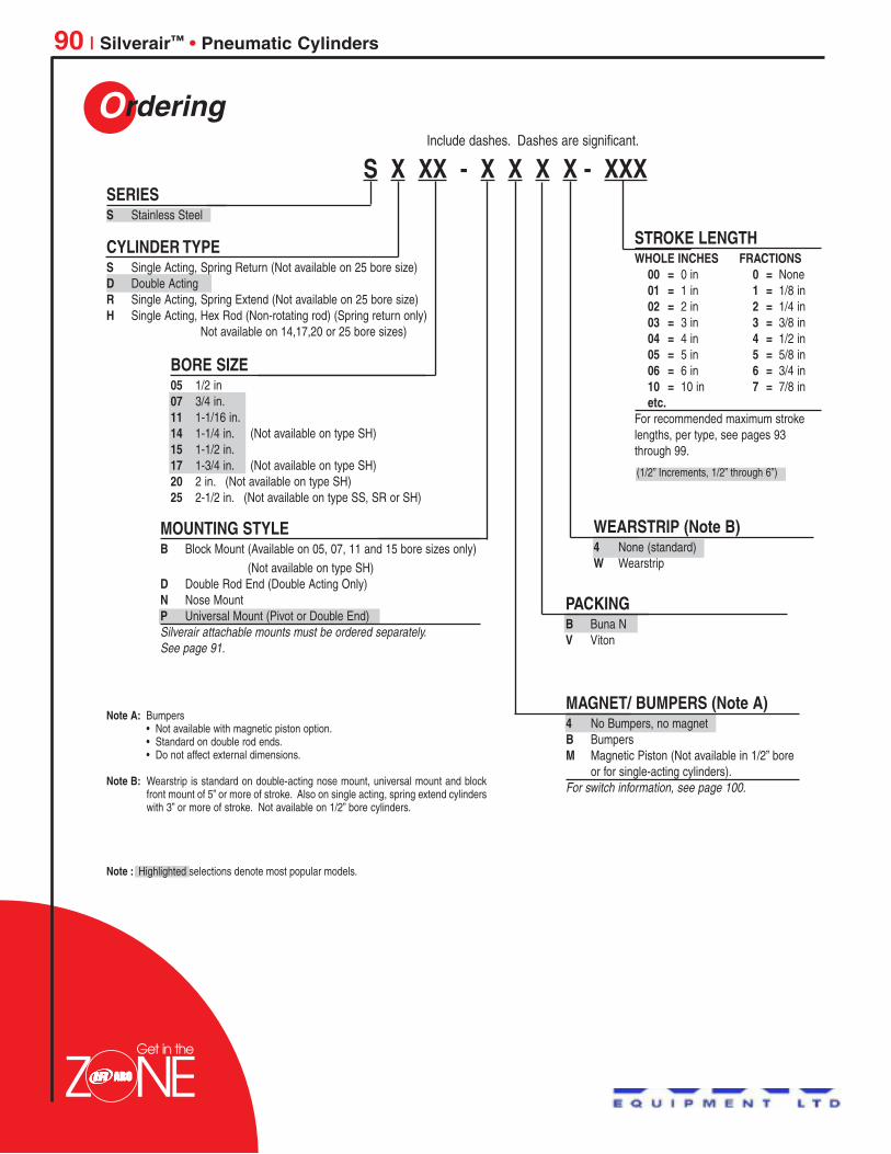
90 | Silverair™ • Pneumatic Cylinders
CYLINDER TYPES Single Acting, Spring Return (Not available on 25 bore size)D Double ActingR Single Acting, Spring Extend (Not available on 25 bore size)H Single Acting, Hex Rod (Non-rotating rod) (Spring return only)
Not available on 14,17,20 or 25 bore sizes)
SERIESS Stainless Steel
Include dashes. Dashes are significant.
S X XX - X X X X - XXX
STROKE LENGTHWHOLE INCHES FRACTIONS
00 = 0 in 0 = None01 = 1 in 1 = 1/8 in02 = 2 in 2 = 1/4 in03 = 3 in 3 = 3/8 in04 = 4 in 4 = 1/2 in05 = 5 in 5 = 5/8 in06 = 6 in 6 = 3/4 in10 = 10 in 7 = 7/8 inetc.
For recommended maximum strokelengths, per type, see pages 93through 99.
MOUNTING STYLEB Block Mount (Available on 05, 07, 11 and 15 bore sizes only)
(Not available on type SH)D Double Rod End (Double Acting Only)N Nose Mount P Universal Mount (Pivot or Double End)Silverair attachable mounts must be ordered separately.See page 91.
MAGNET/ BUMPERS (Note A)4 No Bumpers, no magnetB BumpersM Magnetic Piston (Not available in 1/2” bore
or for single-acting cylinders).For switch information, see page 100.
WEARSTRIP (Note B)4 None (standard)W Wearstrip
PACKINGB Buna NV Viton
BORE SIZE05 1/2 in07 3/4 in.11 1-1/16 in.14 1-1/4 in. (Not available on type SH)15 1-1/2 in.17 1-3/4 in. (Not available on type SH)20 2 in. (Not available on type SH)25 2-1/2 in. (Not available on type SS, SR or SH)
Note A: Bumpers• Not available with magnetic piston option.• Standard on double rod ends.• Do not affect external dimensions.
Note B: Wearstrip is standard on double-acting nose mount, universal mount and blockfront mount of 5” or more of stroke. Also on single acting, spring extend cylinderswith 3” or more of stroke. Not available on 1/2” bore cylinders.
Note : Highlighted selections denote most popular models.
(1/2” Increments, 1/2” through 6”)
Get in the
Colin
Logo1

Get in the
Silverair™ • Pneumatic Cylinders | 91
Ordering
CYLINDER BORE (INCHES)1/2 3/4 1-1/16 1-1/4 1-1/2 1-3/4 2 2-1/2
Mounting NutL-Mount
Block Front Mount Pivot Bracket and Rod Clevis
☛ FOR DOUBLE END MOUNTING OF SINGLE-ACTING CYLINDERS, ORDER THE FOLLOWING:
1/2-inch bore One 118108-05 L-Mount and one 118109-05 Nut for rear mounting thread. One 118108-50 L-Mountand one 118109-50 Nut for front mounting thread.
3/4-inch bore Two 118108-07 L-Mounts, one 118109-07 Nut for rear mounting thread and one 118109-11 Nut for frontmounting thread.
NOTE: Silverair accessories are bright zinc plated steel.
Series S (Mounting Kits)
L-MOUNT (Single Acting)Order Mounting Nut below.118108-05 118108-07 118108-11 118108-14 118108-14 118108-17 118108-20 118108-25
L-MOUNT (Double Acting)Order Mounting Nut below.118108-50 118108-11 118108-11 118108-14 118108-14 118108-17 118108-20 118108-25
MOUNTING NUT (Single Acting*)118109-05 118109-07 118109-11 118109-14 118109-14 118109-17 118109-20 118109-25
MOUNTING NUT (Double Acting)118109-50 118109-11 118109-11 118109-14 118109-14 118109-17 118109-20 118109-25
PIVOT BRACKET (Pivot Pin Included)117523-05 117523-07 117523-07 117523-14 117523-15 117523-15 117523-20 117523-20
ROD CLEVIS (Pivot Pin Included)117555-05 117555-07 117555-11 117555-14 117555-14 117555-17 117555-17 117555-17
PIVOT PINS (Standard Equipment)Pin118119-05 118119-07 118119-07 118119-14 118119-15 118119-15 118119-20 -Retainer118592-05 118592-05 118592-05 118592-05 118592-15 118592-15 118592-15 -Optional Press Fit Pin118121-05 118121-07 118121-07 118121-14 118121-15 118121-15 – -
SILVERAIRCYLINDERS
Colin
Logo1

Dimensional Data
92 | Silverair™ • Pneumatic Cylinders
Series S (Mounting Kit)
CYLINDER BORE (INCHES)1/2 3/4 1-1/16 1-1/4 1-1/2 1-3/4 2 2-1/2
Dim Single Double Single Double All All All All All AllRef Acting Acting Acting Acting Types Types Types Types Types Types
L-MOUNT BRACKETA .31 .31 .44 .56 .56 .75 .75 .94 1.00 1.00B .19 .19 .19 .27 .27 .28 .28 .34 .34 .34C .62 .62 .75 1.00 1.00 1.50 1.50 1.50 1.62 1.62D 1.00 1.00 1.25 1.50 1.50 1.89 1.89 2.25 2.25 2.88E .37 .37 .40 .56 .56 .75 .75 .88 1.00 1.25F .38 .44 .50 .63 .63 .76 .76 1.04 1.38 1.50G .56° .56° .45° .45° .45° .49° .49° .52° .60° .63°H .57 .57 .69 .81 .81 1.00 1.00 1.25 1.50 1.75J 1.38 1.38 1.63 1.88 1.88 2.50 2.50 3.00 3.00 3.75
MOUNTING NUTA .56 .68 .75 .93 .93 1.12 1.12 1.50 1.85 2.06B .22 .25 .31 .37 .37 .42 .42 .56 .50 .50C 3/8-24 7/16-20 1/2-20 5/8-18 5/8-18 3/4-16 3/4-16 1-14 1-1/4-12 1-3/8-12
CYLINDER BORE (INCHES)1/2 3/4 1-1/16 1-1/4 1-1/2 1-3/4 2 2-1/2
Dim All All All All All All All AllRef Types Types Types Types Types Types Types Types
PIVOT BRACKETA .20 .26 .26 .32 .39 .39 .45 .45B .52 .65 .65 .77 .96 .96 1.20 1.20C .43 .75 .75 .75 1.00 1.00 1.00 1.00D .54 .87 .87 .94 1.25 1.25 1.43 1.43E .22 .31 .31 .31 .38 .38 .38 .38F .16 .26 .26 .26 .38 .38 .38 .38G .50° .53° .53° .53° .52° .52° .48° .48°H .64 .87 .87 1.06 1.37 1.37 1.68 1.68J .75 1.19 1.19 1.25 1.63 1.63 1.81 1.81
ROD CLEVISA .38 .50 .50 .75 .75 .75 .75 .75B .19 .25 .25 .38 .38 .38 .38 .38C .75 .94 .94 1.30 1.30 1.30 1.30 1.30D .38 .50 .50 .75 .75 .75 .75 .75E 10-32 1/4-28 5/16-24 7/16-20 7/16-20 1/2-20 1/2-20 1/2-20F .19 .25 .25 .38 .38 .38 .38 .38G .94 1.20 1.20 1.70 1.70 1.70 1.70 1.70H .12 .16 .16 .25 .25 .31 .31 .31
PIVOT PINAs supplied with Pivot Bracket:
A .69 .81 .81 .94 1.13 1.13 1.44 1.44B .15 .25 .25 .25 .37 .37 .37 .37
For press fit into pivot hole:A .50 .75 .75 .87 1.12 1.12 – –B .15 .24 .24 .24 .37 .37 – –C .17 .26 .26 .26 .39 .39 – –
A B
C
A D
C
B
E
H
J
F
G
D
C
E
J
H
GF
A B
L-Mount
Mounting Nut
Pivot Bracket
ASQ
D
C
B
E
HG
F
Rod Clevis
A
A
B
B C
Pivot Pins
Colin
Logo1

Performance Specifications
Silverair™ • Pneumatic Cylinders | 93
Dimensional Data
Model SSXX-N4B4-XXX (Max. Stroke - 4 inches)
Bore sizes: 1/2”, 3/4”, 1-1/16”, 1-1/4”, 1-1/2” 1-3/4”, 2”Hex Mounting Nut: Standard (except on 2-inch models).Options: Wearstrip (except on 1/2-inch bore), bumper,
VitonAccessories: L-mount, rod clevisNotes: No rod bushing on 1/2-inch models - front head
is hard anodized.
Model SHXX-N4B4-XXX (Max. Stroke - 4 inches)NonrotatingBore sizes: 1/2”, 3/4”, 1-1/16”, 1-1/2”Hex Mounting Nut: StandardOptions: Wearstrip (except on 1/2-inch bore)Accessories: L-mount, rod clevisNotes: No rod bushing - front head is hard
anodized.
MM
GGNN
KK HH
JJ ThreadDD
CCRT BB
QM
LL (NPT)
A + (AS per 1” stroke)
FA (Thread Length)
Series S (Spring Return, Nose Mount)
Series S (Spring Return, Universal Mount)
Series S (Spring Return, Nose Mount)
Series S (Spring Return, Universal Mount)
Model SSXX-P4B4-XXX (Max. Stroke - 4 inches)
Bore sizes: 1/2”, 3/4”, 1-1/16”, 1-1/4”, 1-1/2”, 1 3/4”, 2”Options: Wearstrip (except on 1/2-inch bore), bumper,
VitonAccessories: Pivot bracket, rod clevis, L-mount, mounting
nut.Order mounting nuts as required.Notes: No rod bushing on 1/2-inch models - front head
is hard anodized.
MM
HHKK
NN GG
DDPP
CCBB
LL (NPT)JJ Thread
EPQQ
RR
JA
A + (AS per 1” stroke)
FF + (AS per 1” stroke)
FA (thread length)
Spring ForcesBore Spring Force (lbs.)Size Normal Actuated
1/2” 1 23/4” 1.5 5
1-1/16” 4 81-1/4” 7 141-1/2” 6 121-3/4” 12 24
2” 15 30
Model SHXX-P4B4-XXX (Max. Stroke - 4 inches)NonrotatingBore sizes: 1/2”, 3/4”, 1-1/16”, 1-1/2”Options: Wearstrip (except on 1/2-inch bore), bumper,VitonAccessories: Pivot bracket, rod clevis, L-mount, mounting nut.
Order mounting nuts as required.Notes: No rod bushing - front head is hard anodized.
Get in the
SILVERAIRCYLINDERS
Colin
Logo1

Dimensional Data
94 | Silverair™ • Pneumatic Cylinders
CYLINDER BORE (INCHES)Dim Cylinder
Code Description 1/2 3/4 1-1/16 1-1/4 1-1/2 1-3/4 2
Series S
Get in the
SINGLE ACTINGA SSXX-N4B4-XXX 1.81 2.00 2.56 3.41 3.19 3.85 4.17
A SHXX-N4B4-XXX 2.06 2.25 2.68 – 3.44 – –
A SSXX-P4B4-XXX 2.50 3.06 3.44 4.50 4.25 5.41 5.54
A SHXX-P4B4-XXX 2.75 3.31 3.56 – 4.50 – –
AS SSXX-N4B4-XXX 1.88 1.69 1.56 1.81 1.69 2.00 2.00
AS SHXX-N4B4-XXX 1.88 1.69 1.56 – 1.69 – –
AS SSXX-P4B4-XXX 1.88 1.69 1.56 1.81 1.69 2.00 2.00
AS SHXXP4B4-XXX 1.88 1.69 1.56 – 1.69 – –
BB SSXX-N4B4-XXX .31 .44 .50 .62 .62 .75 .81
BB SHXX-N4B4-XXX .31 .44 .50 – .62 – –
BB SSXX-P4B4-XXX .31 .44 .50 .62 .62 .75 .81
BB SHXXP4B4-XXX .31 .44 .50 – .62 .75 .81
CC SSXX-XXXX-XXX .50 .50 .62 1.00 1.00 1.19 –
CC SHXX-XXXX-XXX .75 .75 .75 – 1.25 – –
DD All Types .04 .07 .07 .07 .07 .09 .12
EP All Types .42 .66 .62 .91 .81 .98 1.00
FA All Types .50 .50 .50 .50 .75 .88 .88
FF SSXX-X4B4-XXX 4.50 2.77 3.16 4.14 3.88 4.91 5.11
GG All Types .375 .500 .625 .750 .750 1.03 1.375
HH All Types 10-32 1/4-28 5/16-24 7/16-20 7/16-20 1/2-20 1/2-20
JA SSXX-N4B4-XXX 7/16-20 5/8-18 5/8-18 3/4-16 3/4-16 1-14 1-1/4-12
JA SHXX-N4B4-XXX 3/8-24 5/8-18 5/8-18 – 3/4-16 – –
JJ All Types 3/8-24 1/2-20 5/8-18 3/4-16 3/4-16 1-14 1-1/4-12
KK Wrench Flat None None .25 .38 .38 .44 .50
LL All Types 10-32 1/8 1/8 1/8 1/8 1/4 1/4
MM All Types .56 .81 1.12 1.31 1.55 1.81 2.07
NN Standard Rod .187 .250 .312 .437 .437 .500 .625
NN Hex Flats .187 .250 .375 – .437 – –
PP All Types .25 .34 .34 .41 .50 .50 .57
QM All Types .37 .62 .87 .87 .82 1.25 1.25
QQ All Types .31 .38 .38 .50 .62 .62 .75
RR All Types .16 .25 .25 .25 .38 .38 .38
RT All Types .12 .16 .25 .18 .25 .25 .31
Colin
Logo1

Performance Specifications
Silverair™ • Pneumatic Cylinders | 95
Dimensional Data
Series S (Spring Extend, Nose Mount)
Series S (Spring Extend, Nose Mount)
Series S (Spring Extend, Universal Mount)
Series S (Spring Extend, Universal Mount)
Model SRXX-N4B4-XXX (Max. Stroke - 4 inches)Bore sizes: 1/2”, 3/4”, 1-1/16”, 1-1/4”, 1-1/2”, 1-3/4”, 2”Hex Mounting Nut: StandardOptions: Bumper, VitonAccessories: Rod clevis, L-mountWearstrip: Not available on 1/2-inch bore.
Standard with 3 inches of stroke, or more(optional on shorter strokes).
Notes: No rod bushing on 1/2-inch models - front headis hard anodized.
Series S (Block Front Mount - Spring Extend or Spring Return
Series S (Block Front Mount - Spring Extend or Spring Return
Model SRXX-P4B4-XXX (Max. Stroke - 4 inches)Bore sizes: 1/2”, 3/4”, 1-1/16”, 1-1/4”, 1-1/2”, 1-3/4’, 2”Options: Bumper, VitonAccessories: Pivot bracket, rod clevis, L-mount, mounting
nut.Wearstrip: Not available on 1/2-inch bore.
Standard with 3 inches of stroke, or more(optional on shorter strokes).
Notes: No rod bushing on 1/2-inch models - front headis hard anodized.
Model SSXX-B4B4-XXX (Spring Return)
(Max. Stroke - 4 inches)Bore sizes: 1/2”, 3/4’, 1-1/16”Options: Wearstrip (except on 1/2-inch bore), bumpers,
Viton.Accessories: Rod clevisNotes: No rod bushing on 1/2-inch models - front head
is hard anodized.head is hard anodized.
Model SRXX-B4B4-XXX (Spring Extend, Illustrated)
(Max. Stroke - 4 inches)Bore Sizes: 1/2”, 3/4”, 1-1/16”Options: Bumpers, VitonAccessories: Rod clevisWearstrip: Not available on 1/2-inch bore.
Standard with 3 inches of stroke, or more(optional on shorter strokes).
Notes: No rod bushing on 1/2-inch models - front headis hard anodized.
MM
GGNN
KK HH
JJ ThreadDD
CC+ strokeRT BBEE
QM
LL (NPT) LL (NPT)
A + (AS per 1” stroke)
FA (thread length)
MM
GGNN
KK HH
JJ ThreadDD
CC+ strokeRT BBEE
QM
LL (NPT) LL (NPT)
A + (AS per 1” stroke)
FA (thread length)
MM
GGNN
KK HH
JJ ThreadDD
CC+ strokeRT BBEE
QM
LL (NPT) LL (NPT)
A + (AS per 1” stroke)
FA (thread length)
Spring ForcesBore Spring Force (lbs.)Size Normal Actuated
1/2” 1 23/4” 1.5 5
1-1/16” 4 81-1/4” 7 141-1/2” 6 121-3/4” 12 24
2” 15 30
* TT - Two thru holes drilled and counterbored on portside for cap screw size listed.
** TW - Above thru holes tapped on opposite side foradditional mounting option.
† Mounting hole locations for 1/2-inch models.
Get in the
SILVERAIRCYLINDERS
Colin
Logo1

96 | Silverair™ • Pneumatic Cylinders
Dimensional Data
CYLINDER BORE (INCHES)Dim Cylinder
Code Description 1/2 3/4 1-1/16 1-1/4 1-1/2 1-3/4 2
Series S
SINGLE ACTINGA SRXX-N4B4-XXX 2.42 2.78 3.28 4.25 4.00 5.03 5.11
A SRXX-P4B4-XXX 3.12 3.84 4.15 5.33 5.06 6.59 6.48
A SSXX-B4B4-XXX 2.42 3.34 4.28 – 5.00 – –
A SRXX-B4B4-XXX 2.42 3.34 4.28 – 5.18 – –
AS SRXX-N4B4-XXX 1.44 2.69 2.56 2.81 2.69 3.00 3.00
AS SRXX-P4B4-XXX 1.44 2.69 2.56 2.81 2.69 3.00 3.00
AS SSXX-B4B4-XXX 1.88 1.69 1.56 – 1.69 – –
AS SRXX-B4B4-XXX 2.88 2.69 2.56 – 2.69 – –
BB All Types .41 .50 .50 .62 .62 .75 .81
BC Bolt Circle Dia. .75 1.00 1.25 – 1.75 – –
BT Threaded Hole 8-32(2) 10-32(2) 10-32(2) – 1/4-20 – –
CC SRXX-N4B4-XXX .50 .50 .62 1.00 1.00 1.19 1.25
CC SRXX-P4B4-XXX .50 .50 .62 1.00 1.00 1.19 1.25
CC SRXX-B4B4-XXX .50 1.06 1.12 – 1.50 – –
CC SSXX-B4B4-XXX .50 1.06 1.12 – 1.50 – –
DD Block Front Mount .06 .09 .09 – .12 – –
DD All Others .04 .07 .07 .07 .07 .09 .12
E Block Front Mount .75 1.00 1.25 – 1.75 – –
EE All Types .37 .48 .52 .69 .62 .72 .69
EP SRXX-P4B4-XXX .42 .66 .62 .91 .81 .98 1.00
FA Block Front .50 .75 .75 – 1.25 – –
FA All Others .50 .50 .50 .50 .75 .88 .88
FF SRXX-P4B4-XXX 5.76 3.55 3.87 4.97 4.69 6.09 6.05
FM Block Front Mount .31 .48 .72 – 1.00 – –
GG Block Front Mount .437 .625 .750 – 1.00 – –
GG SRXX-XXXX-XXX .437 .625 .625 .750 .750 1.03 1.375
HH All Types 10-32 1/4-28 5/16-24 7/16-20 7/16-20 1/2-20 1/2-20
JA SRXX-P4B4-XXX 7/16-20 5/8-18 5/8-18 3/4-16 3/4-16 1-14 1-1/4-12
JJ All Types 7/16-20 5/8-18 5/8-18 3/4-16 3/4-16 1-14 1-1/4-12
KK Wrench Flat None None .25 .38 .38 .44 .50
LL Block Front Mount 10-32 1/8 1/8 1/8 1/4 – –
LL All Others 10-32 1/8 1/8 1/8 1/8 1/4 1/4
MM All Types .62 .88 1.12 1.31 1.55 1.81 2.07
NN All Types .187 .250 .312 .437 .437 .500 .625
PM Block Front Mount .44 .51 .54 – .66 – –
PP SRXX-P4B4-XXX .25 .34 .34 .41 .50 .50 .57
QM All Types .37 .62 .87 .87 .82 1.25 1.25
QQ SRXX-P4B4-XXX .31 .38 .38 .50 .62 .62 .75
RR SRXX-P4B4-XXX .16 .25 .25 .25 .38 .38 .38
RT All Types .12 .16 .25 .18 .25 .25 .31
TN Block Front Mount .44 .62 .81 – 1.12 – –
TT Block Front Mount 8-32 10-32 10-32 – 1/4-20 – –
TW Block Front Mount – 1/4-20 1/4-20 – 5/16-18 – –
Colin
Logo1
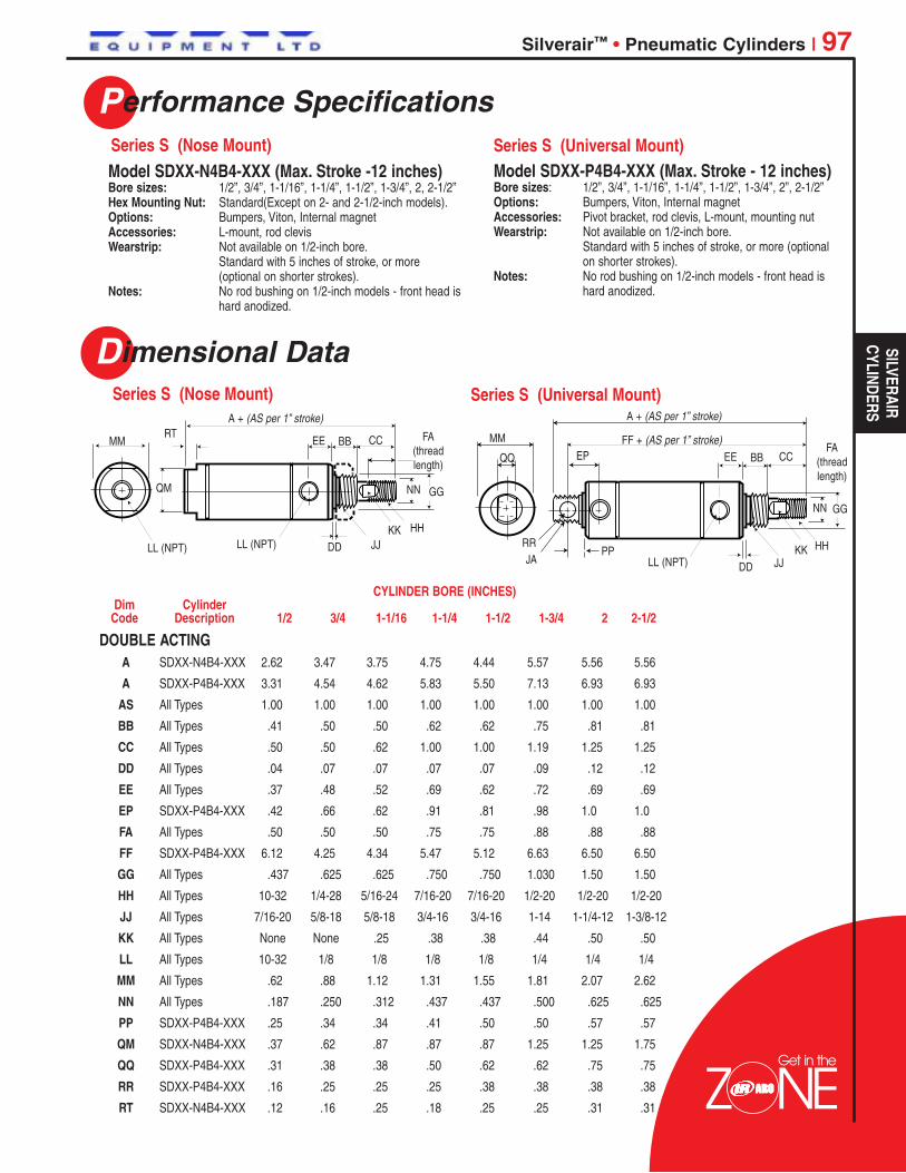
Silverair™ • Pneumatic Cylinders | 97
Model SDXX-N4B4-XXX (Max. Stroke -12 inches)Bore sizes: 1/2”, 3/4”, 1-1/16”, 1-1/4”, 1-1/2”, 1-3/4”, 2, 2-1/2”Hex Mounting Nut: Standard(Except on 2- and 2-1/2-inch models).Options: Bumpers, Viton, Internal magnetAccessories: L-mount, rod clevisWearstrip: Not available on 1/2-inch bore.
Standard with 5 inches of stroke, or more(optional on shorter strokes).
Notes: No rod bushing on 1/2-inch models - front head ishard anodized.
Model SDXX-P4B4-XXX (Max. Stroke - 12 inches)Bore sizes: 1/2”, 3/4”, 1-1/16”, 1-1/4”, 1-1/2”, 1-3/4”, 2”, 2-1/2”Options: Bumpers, Viton, Internal magnetAccessories: Pivot bracket, rod clevis, L-mount, mounting nutWearstrip: Not available on 1/2-inch bore.
Standard with 5 inches of stroke, or more (optionalon shorter strokes).
Notes: No rod bushing on 1/2-inch models - front head ishard anodized.
MM EE
NN GG
DD JJKK HH
FA(threadlength)
LL (NPT)
BB CC
A + (AS per 1” stroke)RT
QM
LL (NPT)
Performance Specifications
Dimensional Data
Series S (Nose Mount) Series S (Universal Mount)
Series S (Nose Mount) Series S (Universal Mount)
LL (NPT)
MM
RR
DDKK
JJJAHH
EE BB
NN GG
CC
PP
EPQQ
A + (AS per 1” stroke)
FF + (AS per 1” stroke)FA
(threadlength)
CYLINDER BORE (INCHES)Dim Cylinder
Code Description 1/2 3/4 1-1/16 1-1/4 1-1/2 1-3/4 2 2-1/2
Get in the
DOUBLE ACTINGA SDXX-N4B4-XXX 2.62 3.47 3.75 4.75 4.44 5.57 5.56 5.56
A SDXX-P4B4-XXX 3.31 4.54 4.62 5.83 5.50 7.13 6.93 6.93
AS All Types 1.00 1.00 1.00 1.00 1.00 1.00 1.00 1.00
BB All Types .41 .50 .50 .62 .62 .75 .81 .81
CC All Types .50 .50 .62 1.00 1.00 1.19 1.25 1.25
DD All Types .04 .07 .07 .07 .07 .09 .12 .12
EE All Types .37 .48 .52 .69 .62 .72 .69 .69
EP SDXX-P4B4-XXX .42 .66 .62 .91 .81 .98 1.0 1.0
FA All Types .50 .50 .50 .75 .75 .88 .88 .88
FF SDXX-P4B4-XXX 6.12 4.25 4.34 5.47 5.12 6.63 6.50 6.50
GG All Types .437 .625 .625 .750 .750 1.030 1.50 1.50
HH All Types 10-32 1/4-28 5/16-24 7/16-20 7/16-20 1/2-20 1/2-20 1/2-20
JJ All Types 7/16-20 5/8-18 5/8-18 3/4-16 3/4-16 1-14 1-1/4-12 1-3/8-12
KK All Types None None .25 .38 .38 .44 .50 .50
LL All Types 10-32 1/8 1/8 1/8 1/8 1/4 1/4 1/4
MM All Types .62 .88 1.12 1.31 1.55 1.81 2.07 2.62
NN All Types .187 .250 .312 .437 .437 .500 .625 .625
PP SDXX-P4B4-XXX .25 .34 .34 .41 .50 .50 .57 .57
QM SDXX-N4B4-XXX .37 .62 .87 .87 .87 1.25 1.25 1.75
QQ SDXX-P4B4-XXX .31 .38 .38 .50 .62 .62 .75 .75
RR SDXX-P4B4-XXX .16 .25 .25 .25 .38 .38 .38 .38
RT SDXX-N4B4-XXX .12 .16 .25 .18 .25 .25 .31 .31
SILVERAIRCYLINDERS
Colin
Logo1

Get in the
98 | Silverair™ • Pneumatic Cylinders
Model SDXX-D4B4-XXX (Max. Stroke - 12 inches)Bore sizes: 1/2”, 3/4”, 1-1/16”, 1-1/4”, 1-1/2”, 1-3/4”, 2”, 2-1/2”Hex Mounting Nut: Standard (except on 2 and 2-1/2 inch models) and bumpers.Options: Viton, wearstrip.Accessories: L-mount, rod clevis, mounting nut (2-, 2-1/2-inch models)Notes: No rod bushing on 1/2-inch models - heads are hard anodized.
Model SDXX-B4B4-XXX (Max. Stroke - 12 inches)Bore sizes: 1/2”, 3/4”, 1-1/16”Options: Internal magnet, bumpers, Viton, wearstripAccessories: Rod clevisWearstrip: Not available on 1/2-inch bore.
Standard with 5 inches of stroke, or more (optional on shorter strokes).Notes: No rod bushing on 1/2-inch models - front head is hard anodized.
Wearstrip not available on 1/2-inch boreWearstrip is standard with 5 inches of stroke, or more (optional on shorter strokes).
MM EE
NN GG
DDJJ
KK HH
FA (thread length)
BB CC
A + (2 x AS per 1” stroke)
FF + (AS per 1” stroke)
LL (NPT)
RT
LL (NPT)DD
KK
E
BT
BC
HH
PM FM
NN GG
CCFA
TT*TW**
TN
†
†
QM
A + (AS per 1” stroke)
* TT - Two thru holes drilled and counterbored on port side for cap screw size listed.
** TW - Above thru holes tapped on opposite side for additional mounting option.
† Mounting hole locations for 1/2-inch models.
Performance Specifications
Dimensional Data
Series S (Double Rod End, Double End Mount)
Series S (Block Front Mount)
Series S (Double Rod End, Double End Mount)
Series S (Block Front Mount)
Colin
Logo1

Silverair™ • Pneumatic Cylinders | 99
Dimensional Data
DOUBLE ACTINGA SDXX-D4B4-XXX 3.88 5.03 5.32 6.83 6.63 8.57 8.31 8.31
A Block Front Mount 2.62 4.03 4.75 – 5.44 – – –
AS Block Front Mount 1.00 1.00 1.00 – 1.00 – – –
AS SDXX-D4B4-XXX .50 1.00 1.00 1.00 1.00 1.00 1.00 1.00
BB SDXX-D4B4-XXX .41 .50 .50 .62 .62 .75 .81 .81
BC Bolt Circle Dia. .75 1.00 1.25 – 1.75 – – –
BT Threaded Hole 8-32 10-32 10-32 – 1/4-20 – – –
CC Block Front Mount .50 1.06 1.12 – 1.50 – – –
CC SDXX-D4B4-XXX .50 .50 .62 1.00 1.00 1.19 1.25 1.25
DD Block Front Mount .06 .09 .09 – .12 – – –
DD SDXX-D4B4-XXX .04 .07 .07 .07 .07 .09 .12 .12
E Block Front Mount .75 1.00 1.25 – 1.75 – – –
EE SDXX-D4B4-XXX .37 .48 .52 .69 .62 .72 .69 .69
FA Block Front Mount .50 .75 .75 – 1.25 – – –
FA SDXX-D4B4-XXX .50 .50 .50 .75 .75 .88 .88 .88
FF SDXX-D4B4-XXX 2.07 3.03 3.07 3.58 3.39 4.69 4.19 4.19
FM Block Front Mount .31 .48 .72 – 1.00 – – –
GG Block Front Mount .437 .625 .750 – 1.00 – – –
GG SDXX-D4B4-XXX .437 .625 .625 .750 .750 1.030 1.50 1.50
HH All Types 10-32 1/4-28 5/16-24 7/16-20 7/16-20 1/2-20 1/2-20 1/2-20
JJ SDXX-D4B4-XXX 7/16-20 5/8-18 5/8-18 3/4-16 3/4-16 1-14 1-1/4-12 1-3/8-12
KK All Types None None .25 .38 .38 .44 .50 .50
LL All Types 10-32 1/8 1/8 1/8 1/8 1/4 1/4 1/4
MM SDXX-D4B4-XXX .62 .88 1.12 1.31 1.55 1.81 2.07 2.62
NN All Types .187 .250 .312 .437 .437 .500 .625 .625
PM Block Front Mount .44 .51 .54 – .66 – – –
QM Block Front Mount .37 .62 .87 – .87 – –
RT Block Front Mount .12 .16 .25 – .25 – – –
TN Block Front Mount .44 .62 .81 – 1.12 – – –
TT Block Front Mount 8-32 10-32 10-32 – 1/4-20 – – –
TW Block Front Mount – 1/4-20 1/4-20 – 5/16-18 – – –
CYLINDER BORE (INCHES)Dim Cylinder
Code Description 1/2 3/4 1-1/16 1-1/4 1-1/2 1-3/4 2 2-1/2
Get in the
SILVERAIRCYLINDERS
Colin
Logo1

Performance Specifications
Features
Ordering
100 | Silverair™ • Pneumatic Cylinders
Hall Effect Sensors are typically used in conjunction with computers,programmable controllers or other solid state devices to sense andprocess cylinder rod proximity. The solid state circuitry in this sinkingswitch (NPN) provides clean, fast output without “bounce.” The 300mW power capability restricts its use to low power loads. One switchkit fits all Silverair cylinders for reduced and simplified inventory. 3/8inch effective area per switch. For two switches, a minimum of 1-inchstroke is recommended.
Series S (Hall Effect Switches)
Series S (Reed Switches)
Series S (Hall Effect Switches)
Series S (Reed Switches)
Series S (Hall Effect Switches)
Series S (Reed Switches)
Epoxy encapsulated reed switches are ideal for harshenvironments. One switch kit fits all Silverair cylinders for reducedand simplified inventory. 50 watt reed is common in all sensors.Model 117045-300 lights up during reed engagement in low voltageapplications. Model 117045-500 lights up over wide voltage range.Model 117045-100 is a basic sensor with no LED.
Input Voltage: 5 to 24 VDCInput Current: 25 mA maximumOutput Voltage Drop: 0.4 VDC maximumOutput Current: 330 mA maximumPower Dissipation: 300 mW maximumTemperature Range: -20° to 185°F (-29° to 85°C)
Contacts: Normally openContact Rating: 50 W maximumSwitching Current: 1 A maximumInitial Contact Resistance: 1 OhmMinimum Break Down Voltage: 225 VDC, 275 VACTemperature Range: -40° to 200°F (-40° to 93°C)
Model No. Description
118123-100 w/LED, 5-24 VDC, 24 inch leads (includes 118124 Mounting Kit)118123-200 w/LED, 5-24 VDC, 144 inch leads (includes 118124 Mounting Kit)
One 118124 Mounting Kit is included with each Reed Switch
Model No. Description
117045-100 No LED, 120 VAC or 200 VDC max., 24 inch leads117045-200 No LED, 120 VAC or 200 VDC max., 144 inch leads117045-300 w/LED, 5-24 VAC/DC max., 24 inch leads117045-400 w/LED, 5-24 VAC/DC max., 144 inch leads117045-500 w/LED, 120 VAC or 200 VDC max., 24 inch leads117045-600 w/LED, 120 VAC or 200 VDC max., 144 inch leads
Colin
Logo1

Get in the
Performance Specifications
Silverair™ • Pneumatic Cylinders | 101
Dimensional Data
Ordering
FeaturesSeries S (Stainless Steel Volume Chambers)Volume chambers are used wherever there is the need to accumulate or store avolume of air or vacuum, such as a time delay in a circuit.
• Stainless steel body and aluminum endcaps offer excellent corrosion resistancein adverse environments.
• Available in lengths up to 24 inches, at 1/8-inch increments, providing acapability to meet very specific pneumatic accumulator applications.
Operating Pressures: 0 - 200 PSIG (14 bar)Temperatures Ranges: -40° to 160°F, ambient (-40° to 71°C)Operation: Compressed air or with vacuum
CYLINDER BORE (INCHES) Reference 3/4 1-1/16 1-1/2 2
A 1.91 2.18 2.26 2.81
MM .81 1.11 1.55 2.07
QQ .62 .88 .88 1.25
RT .16 .25 .25 .32
PORT .125 .125 .125 .25
A + strokeRT MM
PORT, 2 PL
Note: Highlighted selections denotes mostpopular models.
11811 X - X X X
CHAMBER LENGTHWHOLE INCHES FRACTIONS
00 = 0 in 0 = None01 = 1 in 1 = 1/8 in02 = 2 in 2 = 1/4 in03 = 3 in 3 = 3/8 in04 = 4 in 4 = 1/2 in05 = 5 in 5 = 5/8 in06 = 6 in 6 = 3/4 in10 = 10 in 7 = 7/8 in
etc.• Under 1” stroke, use 00 and
fraction designation.Example: 1/2” stroke = 004
BORE SIZE5 3/4 inch6 1-1/16 inch7 1-1/2 inch8 2 inch
VOLUME CHARTCYLINDER BORE
3/4” 1-1/16” 1-1/2” 2”VOLUME (ci)
Add per1.0 inch .44 .89 1.77 3.14of length
BasicVolume .41 .92 1.80 4.44(add tototal)
(1” Increments, 1” through 4”)
SILVERAIRCYLINDERS
Colin
Logo1

Get in the
Performance Specifications
102 | Economair® • Pneumatic Cylinders
FeaturesSeries 23, 24, & 28 Economair round cylinders are medium to heavy-duty units that can be installedanywhere that a repairable cylinder is desired. Prelubed, they’re suitable foroperation without externally applied lubrication. Unique endcap retention designprovides a concentric assembly, resulting in a service life superior to tie rod cylinderconstruction.
•Cylinder heads are high tensile strength aluminum alloy, retained by a feed ringwire, a simple design that eliminates excess cylinder weight and bulk.
•The barrel I.D. is hard-coated aluminum with a Rockwell C60 hardness. A finishof 16 microinches or better insures low friction and smooth operation.
•Piston rod is ground and polished, hard-chrome plated steel for minimum frictionand maximum packing life. Optional 303 stainless steel is excellent for corrosionresistance and washdown applications (303 stainless steel is standard on 1-1/8-inch bore cylinders).
•Adjustable cushions provide excellent control of cylinder deceleration. Fullrange adjustability (except fixed cushions on 1-1/8-inch bore).
•High grade, self-lubricating bronze rod bearing reduces friction and promotessmooth operation.
•Piston seal selection insures job-matched performance - Buna N O-ring, LowFriction U-cup and self-lubricating packings available.
•Wear compensating rod wiper protects internal seals and parts from dirt, grit anddebris.
• NPTF dry seal pipe threads on ports.
• Optional self-lubricating U-cup seals reduce drag and promote extra cylinder life.
•Cylinder is repairable so instead of buying complete new units, repair kits can beused.
U-cup and Magnetic Piston Options
Bore Sizes: 1-1/8”, 1-1/2”, 2”, 2-1/2”, 3” and 4”
Maximum Output Force: 2,513 pounds (4-inch bore).
Air Pressure: To 200 p.s.i. (14 bar).May be operated hydraulically (200 p.s.i., nonshock).
Operating Temperature Range: 0° to 180° F (-18° to 82° C).
Seals: Viton seals available for high heat applications. Consultfactory.
Notes: Wide range of mounting styles and attachablemounting hardware/ accessories allows cylinders to beapplied in nearly any pneumatic application.
Colin
Logo1

Economair® • Pneumatic Cylinders | 103
Ordering
BORE SIZE18 1-1/8 in 15 1-1/2 in20 2 in25 2-1/2 in30 3 in40 4 in
CYLINDER TYPE1 Double Acting, Rear Tang5 Double Acting, No Rear Tang2 Double Acting, Double Rod
NOTE: Not Available in Series 28
Economair mounts must be ordered separately,see below.
PACKING0 O-Ring, Nitrile2 O-Ring, Low Friction3 O-Ring, Viton4 Lip, Nitrile (pneumatic)5 Lip, Self-Lubricating (low friction)6 Lip, Viton
OPTIONS09 Standard Rod89 303 Stainless Steel Rod
STROKE LENGTHWHOLE INCHES FRACTIONS
00 = 0 in 0 = 0 in01 = 1 in 1 = 1/8 in02 = 2 in 2 = 1/4 in03 = 3 in 3 = 3/8 in04 = 4 in 4 = 1/2 in05 = 5 in 5 = 5/8 in06 = 6 in 6 = 3/4 in↕ ↕ 7 = 7/8 into to 99 99 in
2X XX - X X X9 - XXXInclude dashes ( - ). The dashes are significant.
SERIES NO.23 Noncushioned24 Cushioned, Both Ends28 Magnetic Piston, Cushioned Both Ends
NOTE: 1-1/8 inch bore not available
These packings add oneinch to cylinder length.Viton not available inSeries 28
NOTE: Highlighted selections denote most popular models. Not availablein Series 28
(1” Increments, 1” through 10”plus 1 1/2”, 2 1/2” and 3 1/2”)
Standard on 1-1/8" bore cylinder.
L-Mount (2 qty.) 20533 20534 20534 20535 20535 20536
Flange Mount 20537 20538 20538 20539 20539 20540
Clevis Bracket 20546 20547 20547 20548 20548 20549
Mounting Nut (2 qty.) 20529 20530 20530 20531 20531 20532
Trunnion 20524 20556 20557 20558 20559 20560
Alum. Rod Clevis – 20542 20543 20544 20544 20545
Steel Rod Clevis 20541 115906 115907 115908 115908 115909
CYLINDER BORE (INCHES) 1-1/8 1-1/2 2 2-1/2 3 4
Flange Mount
Mounting NutTrunnion Rod Clevis & Clevis Bracket
NOTE: Order cylinder, rod clevis and clevis bracket separately.Every Economair Cylinder includes rod nut.Trunnion Mount does not include pillow block.
Series 23, 24, & 28
Mounts
L-Mount
ECONO
MAIR
CYLINDERS
Colin
Logo1

Dimensional Data
104 | Economair® • Pneumatic Cylinders
CYLINDER BORE (INCHES)Reference 1-1/8 1-1/2 2 2-1/2 3 4
Rod dia. 0.38 0.50 0.63 0.75 0.75 1.00
A 1.625 3.00 3.00 4.00 4.00 5.00
B 1.281 1.50 1.50 2.00 2.00 2.625
C 1.0 1.688 1.688 2.25 2.25 3.00
D-dia* .250 .250 .250 .375 .375 .438
E .250 .313 .313 .375 .375 .438
F .625 .906 .906 1.219 1.219 1.469
G .375 .500 .500 .625 .625 .750
H 1.00 1.531 1.531 2.094 2.094 2.531
J .750 1.00 1.00 1.25 1.25 1.188
K .375 .469 .469 .781 .781 .781
L-HEX 1.0625 1.438 1.438 2.0625 2.0625 2.50
M-dia. 1.25 1.75 1.75 2.438 2.438 2.938
N 2.00 2.50 2.50 3.375 3.375 4.00
P 2.50 3.25 3.25 4.50 4.50 5.188
Q .688 .594 .594 .719 .719 .844
R 1.219 1.750 1.750 2.375 2.375 3.00
S .313 .313 .313 .375 .375 .438
T 2.250 3.00 3.00 4.00 4.00 5.00
U 1.75 2.25 2.25 3.00 3.00 3.75
V 1.75 2.25 2.25 2.688 2.688 3.375
W 1.406 1.75 1.75 2.0625 2.0625 2.625
X .750 1.00 1.00 1.25 1.25 1.50
Y-dia.* .250 .3125 .3125 .438 .4375 .625
Z .656 .688 .688 .875 .875 1.063
ZZ .3125 .375 .375 .500 .500 .625
TA 3.125 4.125 4.125 5.375 5.625 7.125
TB 2.250 3.00 3.00 3.75 4.25 5.50
TC-dia. .438 .500 .500 .750 .750 .750
TD 2.00 2.625 3.125 4.00 4.500 5.750
TE .875 1.125 1.375 1.875 2.125 2.688
TF .750 1.250 1.250 1.50 1.50 1.50
TG-dia.* .250 .3125 .3125 .4375 .4375 .500
TH-Thd. 3/8-16 1/2-13 5/8-11 3/4-10 3/4-10 1-8
TK – 2.0625 2.0625 2.50 2.50 3.250
TL – .875 .875 1.00 1.00 1.325
TM – 1.0625 1.0625 1.438 1.438 1.938
TN – 1.813 1.00 1.813 1.813 1.50
*Bolt or pin diameter
Series 23, 24, & 28
L-Type
Flange
Clevis Bracket
Mounting Nut
A
A/2
C D
B E
E
FH
PE
QD
N
P/2
P
P/2
T T
UD
S
G
T/2
U
T/2
R
L
M
K
TrunnionAluminum Rod Clevis
TD
TG
TE
TFTA
TB 1/16
TC
ZZ
ZJ TH
Y
X
X
WV
ZZ TM
TN
WTK
ZY THTL
Steel Rod Clevis
Colin
Logo1

Get in the
Economair® • Pneumatic Cylinders | 105
Dimensional DataSeries 23, 24, & 28 (Double Acting with Tang)
(Double Acting, No Tang)
(Double Acting, Double Ended)
(Switch Bracket)
NN Rod Flats
GG
KK
CC BB
EE
EE SS
PP
DD
JJ
GG
TT
MM
CB
DD
HH
FFUU
JJR
Stroke + OO
AA = Double acting with O-ring or low friction packing.LP = Double acting with U cup packing.
Stroke + AAStroke + LP
RR
AA = Double acting with O-ring or low friction packing.LP = Double acting with U cup packing.
NN Rod Flats
GG
FACC
CB
EELL
EE
UU
RT
DD
FF
BB
KK
R
JJHH
Stroke + AAStroke + LP
Stroke + AAStroke + LP Stroke + CBCB
ECONO
MAIR
CYLINDERS
Colin
Logo1

Dimensional Data
106 | Economair® • Pneumatic Cylinders
Series 23, 24, & 28
SwitchSwitch MountingBrackets
Stroke Factor AA* 2.031 2.625 2.625 2.875 2.875 4.00
Stroke Factor LP** 3.031 3.625 3.625 3.875 3.875 5.00
BB .750 1.00 1.00 1.250 1.250 1.250
CB 1.750 2.438 2.438 2.938 2.938 3.500
CC 1.00 1.438 1.438 1.688 1.688 2.250
DD .125 .219 .219 .344 .344 .406
EE .422 .516 .516 .563 .563 .813
FA .781 1.156 1.156 1.375 1.375 1.750
FF▲ .875 1.250 1.250 1.50 1.50 1.875
(± .002) GG .748 1.057 1.057 1.432 1.432 1.777
(UNC-2A) HH 3/8-16 1/2-13 5/8-11 3/4-10 3/4-10 1-8
JJ 3/4-16 1-1/16-18 1-1/16-18 1-3/8-12 1-3/8-12 1-3/4-12UNF-2A UNEF-2A UNEF-2A UNF-2A UNF-2A UN-2A
KK .313 .500 .500 .500 .500 .500
(NPTF) LL 1/8-27 1/4-18 1/4-18 3/8-18 3/8-18 1/2-14
MM 1.375 1.750 2.250 2.750 3.250 4.250
NN .313 .406 .500 .625 .625 .875
OO 3.594 4.688 4.688 5.688 5.688 7.063
PP .688 .875 .875 1.375 1.375 1.438
QQ .375 .500 .500 .625 .625 .750
(RAD.) R .016 .016 .016 .094 .094 .094
RR .250 .313 .313 .438 .438 .500
RT – .172 – .438 .438 .438
SS .969 1.25 1.25 2.00 2.00 2.188
TT – .438 .438 .438 .438 .438
UU – .500 .500 .500 .625 .625
* Double acting with O-ring or low friction packing**Double acting with U-cup packing▲ FF shows total thread, including run out.
Rod Diameter .38 .50 .63 .75 .75 1.00
CYLINDER BORE INCHESDimensionalReference 1-1/8 1-1/2 2 2-1/2 3 4
For more information onPosition Sensors (Switches)see page 116.
NOTE: Order bracket andswitch separately.
Bore Model Number
1-1/8” 119897-18
1-1/2” 119897-15
2” 119897-20
2-1/2” 119897-25
3” 119897-30
4” 119897-40
Model Number 119581-1 119581-2 119581-3 119582-1 119582-2 119582-3 119583-1 119583-2 119583-3
Lead Length/Type 1m bare 3m bare Plug 1m bare 3m bare Plug 1m bare 3m bare Plug
Lead Color Black Grey Black
Switch Type REED PNP(SOURCING) NPN (SINKING)Input Voltage 100 VDC, 125 VAC Max. 10 - 30 VDC 5 - 30 VDC
300mA (150mA Inductive) 5 - 100mA @ 5V
Operating Current 7 - 100mA @ 12V 10 - 200mA @ 12V
- 14 - 200mA @ 24V 20 - 200mA @ 24V
Detecting Distance 2.5 mm 1.5 mm 1.5 mm
Detecting Width 3.0 mm 3.0 mm
Response Time 1 mSec. Min.
LED Function 18mA Min. 1mA Min. 1mA Min.
Switches (Specifications / Ordering)
Colin
Logo1
Get in the
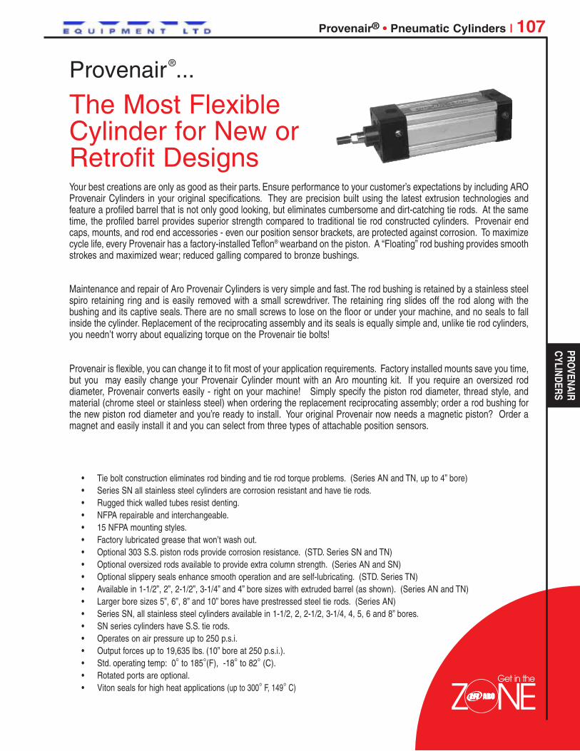
Provenair® • Pneumatic Cylinders | 107
Your best creations are only as good as their parts. Ensure performance to your customer’s expectations by including AROProvenair Cylinders in your original specifications. They are precision built using the latest extrusion technologies andfeature a profiled barrel that is not only good looking, but eliminates cumbersome and dirt-catching tie rods. At the sametime, the profiled barrel provides superior strength compared to traditional tie rod constructed cylinders. Provenair endcaps, mounts, and rod end accessories - even our position sensor brackets, are protected against corrosion. To maximizecycle life, every Provenair has a factory-installed Teflon® wearband on the piston. A “Floating” rod bushing provides smoothstrokes and maximized wear; reduced galling compared to bronze bushings.
Maintenance and repair of Aro Provenair Cylinders is very simple and fast. The rod bushing is retained by a stainless steelspiro retaining ring and is easily removed with a small screwdriver. The retaining ring slides off the rod along with thebushing and its captive seals. There are no small screws to lose on the floor or under your machine, and no seals to fallinside the cylinder. Replacement of the reciprocating assembly and its seals is equally simple and, unlike tie rod cylinders,you needn’t worry about equalizing torque on the Provenair tie bolts!
Provenair is flexible, you can change it to fit most of your application requirements. Factory installed mounts save you time,but you may easily change your Provenair Cylinder mount with an Aro mounting kit. If you require an oversized roddiameter, Provenair converts easily - right on your machine! Simply specify the piston rod diameter, thread style, andmaterial (chrome steel or stainless steel) when ordering the replacement reciprocating assembly; order a rod bushing forthe new piston rod diameter and you’re ready to install. Your original Provenair now needs a magnetic piston? Order amagnet and easily install it and you can select from three types of attachable position sensors.
• Tie bolt construction eliminates rod binding and tie rod torque problems. (Series AN and TN, up to 4” bore)• Series SN all stainless steel cylinders are corrosion resistant and have tie rods.• Rugged thick walled tubes resist denting.• NFPA repairable and interchangeable.• 15 NFPA mounting styles.• Factory lubricated grease that won’t wash out.• Optional 303 S.S. piston rods provide corrosion resistance. (STD. Series SN and TN)• Optional oversized rods available to provide extra column strength. (Series AN and SN)• Optional slippery seals enhance smooth operation and are self-lubricating. (STD. Series TN)• Available in 1-1/2”, 2”, 2-1/2”, 3-1/4” and 4” bore sizes with extruded barrel (as shown). (Series AN and TN)• Larger bore sizes 5”, 6”, 8” and 10” bores have prestressed steel tie rods. (Series AN)• Series SN, all stainless steel cylinders available in 1-1/2, 2, 2-1/2, 3-1/4, 4, 5, 6 and 8” bores.• SN series cylinders have S.S. tie rods.• Operates on air pressure up to 250 p.s.i.• Output forces up to 19,635 lbs. (10” bore at 250 p.s.i.).• Std. operating temp: 0° to 185°(F), -18° to 82° (C).• Rotated ports are optional.• Viton seals for high heat applications (up to 300° F, 149° C)
Provenair®...
The Most FlexibleCylinder for New orRetrofit Designs
PROVENAIR
CYLINDERS
Colin
Logo1

Get in the
Performance Specifications
108 | Provenair® • Pneumatic Cylinders
Aluminum NFPA Interchangeable
Stainless Steel NFPA Interchangeable
Bore sizes: 1/2”, 2”, 2-1/2”, 3-1/4”, 4”, 5”, 6”, 8” and 10”Seals: Buna-N, Viton or Slippery (Aluminum alloy piston with lip-type seals)Barrel: Profiled Extrusion (5”, 6”, 8” and 10” have tie rods.) (Patented)Bushings: “Floating” Rod bushings for low friction, superior wear and side load resistanceSwitches: Metal JacketedPiston Rods: Chrome plated ground and polished high tensile steelOptions: Optional Piston Magnet
Double Rod End303 S.S. Piston RodsStudded male rods for 50% stronger threads than cold rolled thread rod ends
Bore sizes: 1/2”, 2”, 2-1/2”, 3-1/4”, 4”, 5”, 6”, and 8”Rod Bushing: BronzeRod Wiper: Teflon®External Components: 303/304 - End caps, tie rods, piston rods, mounts (barrel is 316)Mounting Styles: 15 NFPAOptions: Optional adjustable cushions
Piston MagnetViton Seals (Wiper Teflon)Double rod ends “GripRidge” gives a
better bracket fasteningsurface. Brackets and
switches stay-put.
End caps and mounts resistcommon coolants, cleaners,
lubricants and corrosion.
Retained cushionadjustment needles
Lightweight aluminumbody resists dents.
Colin
Logo1

Provenair® • Pneumatic Cylinders | 109
Ordering
A H1, C1 (Std.)B H1, C2C H1, C3D H1, C4
F H2, C1G H2, C2H H2, C3J H2, C4
X No CushionsB Cushion Both Ends
H Cushion Head End (Rod End)
C Cushion Cap End
B Buna-NV VitonS Slippery
G Buna-N + Magnetic PistonH Viton + Magnetic PistonJ Slippery + Magnetic Piston
A Chrome, Std Male (KK1)B Chrome, Intermed. Male(KK2)C Chrome, Full Male (CC)D Chrome, Female (KK1)F Chrome, No ThreadsG S.S., Standard Male (KK1)H S.S., Intermediate Male (KK2)J S.S., Full Male (CC)
K S.S., Female (KK1)L S.S., No Threads1 KK1 Chrome, Studded2 KK2 Chrome, Studded3 CC Chrome, Studded4 KK1 SS, Studded5 KK2 SS, Studded6 CC SS, Studded
K 5/8” Note: Available in 1-1/2”, 2” and 2-1/2” bores only.M 1” Note: Available in 2”, 2-1/2”, 3-1/4”, 4” and 5” bores only.P 1 3/8” Note: Available in 3-1/4”, 4”, 5”, 6” and 8” bores only.Q 1 3/4” Note: Available in 6”, 8” and 10” bores only.S 2” Note: Available in 10” bores only.
Q 1- 1/2”S 2”T 2- 1/2”
W 3-1/4”4 4”5 5”
6 6”8 8”Y 10”
TYPEA Double Acting, Single RodB Double Acting, Double Rod
ACTUATORSAluminum actuators begin with A
SERIES (NFPA)All Provenair Cylinders are Series N
SEALS
CUSHIONSPORT LOCATION
(MS4 mounts: Port locations other than “A”, callfactory. Trunnion mounts: ports “A” or “C” only.)
MOUNT(8” and 10” Bore ME3, ME4)(Mounts must be factory installedon 5”, 6”, 8” and 10” Bore)
0 = 0 in1 = 1/8 in2 = 1/4 in3 = 3/8 in4 = 1/2 in5 = 5/8 in6 = 3/4 in7 = 7/8 in
Include dashes ( - ). Dashes are significant.
ROD DIAMETER
ROD STYLE
BORE SIZE NOTE: 5”, 6”, 8” & 10” bores have tie rods.
STROKE
Inches
Tens0-9
0-9
OnesFractions
NA
NOTE:Maximum stroke 99 7/8”,for longer strokes consultfactory. Stroke lengths 20”and longer may requirestop tubes, see page 84.
4
3
2
1Determineport locationlooking atrod end ofcylinder.
See pages 113-119 for Dimensional Drawings
All mounts availablethrough 8” Bore except: * 11/2” - 4” Bore Only **Available 1 1/2” - 10” Bore
A MS1B MS4**C MP1**D MP2**F MF1/ME3**H MF2/ME4**K MP4*L MS7*M MT2
P MT1Q MX1T MX2U MX3X No Mount1 FMB*2 FMC*3 FMH*
Note: Highlighted selections denotes most popular models.
Series AN (1-1/2’ thru 10” Bore)
PROVENAIR
CYLINDERS
Aluminum NFPA
Colin
Logo1

Get in the
Ordering
110 | Provenair® • Pneumatic Cylinders
A H1, C1 (Std.)B H1, C2C H1, C3D H1, C4
F H2, C1G H2, C2H H2, C3J H2, C4
X No CushionsB Cushion Both Ends
H Cushion Head End (Rod End)
C Cushion Cap End
B Buna-NV VitonS Slippery
G Buna-N + Magnetic PistonH Viton + Magnetic PistonJ Slippery + Magnetic Piston
G S.S., Standard Male (KK1)H S.S., Intermediate Male (KK2)J S.S., Full Male (CC)
K S.S., Female (KK1)L S.S., No Threads
K 5/8” Note: Available in 1-1/2”, 2” and 2-1/2” bores only.M 1” Note: Available in 2”, 2-1/2”, 3-1/4”, 4” and 5” bores only.P 1 3/8” Note: Available in 3-1/4”, 4”, 5”, 6” and 8” bores only.Q 1 3/4” Note: Available in 6” and 8” bores only.
Q 1- 1/2”S 2”T 2- 1/2”
W 3-1/4”4 4”5 5”
6 6”8 8”
TYPEA Double Acting, Single RodB Double Acting, Double Rod Note: Not available in 8” bore.
ACTUATORSStainless Steel actuators begin with A
SERIES (NFPA)All Provenair Cylinders are Series N
SEALS
CUSHIONS
PORT LOCATION(MS4 mounts: Port locations otherthan “A”, call factory. Trunnion mounts:ports “A” or “C” only.)
MOUNT(8” Bore ME3, ME4) (Mounts must be factory installed.)
0 = 0 in1 = 1/8 in2 = 1/4 in3 = 3/8 in4 = 1/2 in5 = 5/8 in6 = 3/4 in7 = 7/8 in
Include dashes ( - ). Dashes are significant.
ROD DIAMETER
ROD STYLE
BORE SIZE
STROKE
Inches
Tens0-9
0-9
OnesFractions
NS
NOTE:Maximum stroke 99 7/8”,for longer strokes consultfactory. Stroke lengths 20”and longer may requirestop tubes, see page 84.
4
3
2
1Determineport locationlooking atrod end ofcylinder.
See pages 113-119 for Dimensional Drawings
* 1 1/2” - 6” Bore Only** 1 1/2” - 4” Bore Only
A MS1B MS4**C MP1**F MF1/ME3**H MF2/ME4**K MP4*
M MT2P MT1Q MX1T MX2U MX3X No Mount
Series SN (1-1/2’ thru 8” Bore) NOTE: All SN Series Cylinders have tie rods.
Note: Teflon Wiper Std.
NOTE: S.S. Cylinders are made to order, contact factory for lead time.
Stainless Steel NFPA
Colin
Logo1

Provenair® • Pneumatic Cylinders | 111
Attachable Mounting Kits for Series ANSeries AN (1-1/2”Thru 4” Bore)
Mounting Kits with Long Screws
Mount K
MP4 Detachable Eye
MP2 Detachable Clevis
MP1 Fixed Clevis
Mount C
Mount D
Mount M
MT2 Cap Trunnion MT1 Head Trunnion
4
3
2
1Determineport locationlooking at rodend ofcylinder.
MS7 Side End Lugs (Steel) 119618 119619 119620 119621 119622MF1 Rect. Flange (Steel) 119633 119634 119635 119636 119637MF2 Rect. Flange (Steel) 119646 119647 119648 119649 119650
MP2 HD Clevis (Iron) * 119623 119624 119625 119626 119627MP4 HD Eye (Iron) 119628 119629 119630 119631 119632
MS2 Side Lugs (Alum.) 119638 119639 119640 119641 119642MP1 Fixed Clevis (Alum.) * 119796 119797 119798 119799 119800
Above kits Include all necessary hardware to complete mounting to Provenair cylinders. AN Series only.* Pivot pin included in kit. (Kits not available for 5”,6”,8”, or 10” Bores) (Kits not available for SN Models)
MX1, 2 or 3 Tie Rod Extensions 117822-1 117822-2 117822-2 117822-3 117822-3
1 1/2” 2” 2 1/2” 3 1/4” 4”
Factory Installed Mounts
NOTE: Not all mounts are available on stainless steel models.
MX1 requires two tie rod extension bolt kits (four extension studs per kit). Extension bolts can onlybe used in female retaining bolt mounts: Use mounts 1, 2, 3 or contact factory for conversion kits.
Mount P
PROVENAIR
CYLINDERS
Mount styles B (MS4) and X (No mounts) use mounting kits with long screws to attach through cap into barrel of cylinders.
Mounting Kits with Short Screws
MS7 Side End Lugs (Steel) 115277 115278 115279 115280 115281MP2 HD Clevis (Steel) * 118696 118697 118698 118699 118700MP4 HD Eye (Steel) 118701 118702 118703 118704 118705MF1, MF2 Flange (Steel) 115282 115283 115284 115285 115286MS2 Side Lugs (Steel) 116362 116363 116364 116365 116366
MP1 Fixed Clevis (Alum.) * 115477 115478 115479 115480 115481MP2 Det. Clevis (Alum.) * 115287 115288 115289 115290 115291MP4 Det. Clevis (Alum) * 115292 115293 115294 115295 115296MT1 Head Trunnion (Alum.) 116357 116358 116359 116360 116361MT2 Head Trunnion (Alum.) 116357 116358 116359 116360 116361
1 1/2” 2” 2 1/2” 3 1/4” 4”
Mount styles 1 (FMB), 2 (FMC) and 3 (FMH) use mounting kits with short screws to attach to female sleeve bolts.
Colin
Logo1
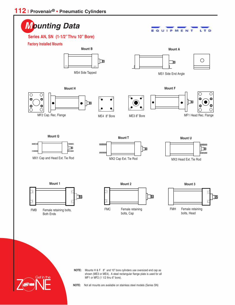
Mounting Data
112 | Provenair® • Pneumatic Cylinders
Mount T Mount U
Mount A
Mount FMount H
Mount 1 Mount 2 Mount 3
Mount Q
MF1 Head Rec. FlangeME4 8” Bore ME3 8” BoreMF2 Cap. Rec. Flange
MX3 Head Ext. Tie RodMX1 Cap and Head Ext. Tie Rod
MS1 Side End Angle
MX2 Cap Ext. Tie Rod
FMB Female retaining bolts,Both Ends
FMC Female retainingbolts, Cap
FMH Female retainingbolts, Head
Mount B
MS4 Side Tapped
NOTE: Not all mounts are available on stainless steel models (Series SN)
NOTE: Mounts H & F 8” and 10” bore cylinders use oversized end cap asshown (ME3 or ME4). A steel rectangular flange plate is used for allMF1 or MF2 (1 1/2 thru 6” bore).
Series AN, SN (1-1/2”Thru 10” Bore)
Factory Installed Mounts
Get in the
Colin
Logo1

Provenair® • Pneumatic Cylinders | 113
Dimensional DataSeries AN , SN (Rod End)
Series AN , SN (With Standard Rod)
CYLINDER BORE (INCHES)1-1/2, 2, 2-1/2 2, 2-1/2 3-1/4, 4 3-1/4, 4 5 5, 6, 8 6, 8, 10 10
ROD DIAMETER (INCHES)5/8 1 1 1-3/8 1 1-3/8 1-3/4 2”
Rod End Dimensions for 1-1/2” - 10” Bore SizesKK1 THD. ( M OR F) 7/16” -20 3/4”-16 3/4”-16 1”-14 3/4”-16 1”-14 1-1/4”-12 1-1/2”-12KK2 THD. (MALE) 1/2”-20 7/8”-14 7/8”-14 1-1/4”-12 7/8”-14 1-1/4”-12 1-1/2”-12 1-3/4”-12CC (MALE) 5/8”-18 1”-14 1”-14 1-3/8”-12 1”-14 1-3/8”-12 1-3/4”-12 2”-12
A .75 1.13 1.13 1.63 1.13 1.63 2.00 2.25B 1.13 1.50 1.50 1.50 1.50 2.00 2.38 2.38C .38 .62 .48 .60 .50 .63 .75 .88D .50 .88 .88 .81 .81 1.13 1.50 1.75F .325 .325 .625 .625 .625 .625 .625 .75
MM .625 1.00 1.00 1.00 1.00 1.375 1.75 2.00V .62 .75 .89 1.02 .25 .38 .38 * .38
* (.50 on10”)
Selection of oversize piston rod affects thefollowing dimensions.ZB XC VZC XD WZD XE WFZE XG CZF XJ VZL XS LAZM XT
See rod end dimensions.
D Flats
B
A
CV
MM
NA
KK1, KK2 orCC Thread
D Flats
B
CV
MM
NA
KK1 ThreadA Depth
KK1 THD.A DEPTH
ROD DIA. MM
KK or CC
A
VC
F
Series AN, TN Bore Sizes 1-1/2”, 2”, 2-1/2”, 3-1/4”, 4”
Series AN Bore Sizes 5”, 6”, 8”, 10”Series SN all Bore Sizes
BUSHING DIA. B
E
▲
▼
Side Tapped MS4MOUNT B
Double Rod End MS4MOUNT B
Rect. Flange – Head-MF1, Cap-MF2MOUNT F & H (1 1/2’ - 4” BORE ONLY)
Head Trunnion MT1Cap Trunnion MT2MOUNT M & P
Side Lug MS2
MMNA
KK1 Thread
B
Y
XTG J
LB + Stroke
SN + Stroke
P + StrokeEE NPTF
ZB + Stroke
ZM + (2x Stroke)ZL + Stroke
PA + Stroke
SN + Stroke
LD + Stroke WF + StrokeG
NT ThreadTK Depth
NT ThreadTK Depth
FFW
WF
ZF + Stroke
ZB + Stroke
1
UTXG
XJ+Stroke
1
TFFB, 4 PL.
E
UF
R
STTSUS
XS
SB, 4PL
SY, 2PLStroke + SS
RT Thread RC Depth
(Female retaining boltseither end)
R
R
BC
E
TN
PROVENAIR
CYLINDERS
Colin
Logo1
114 | Provenair® • Pneumatic Cylinders
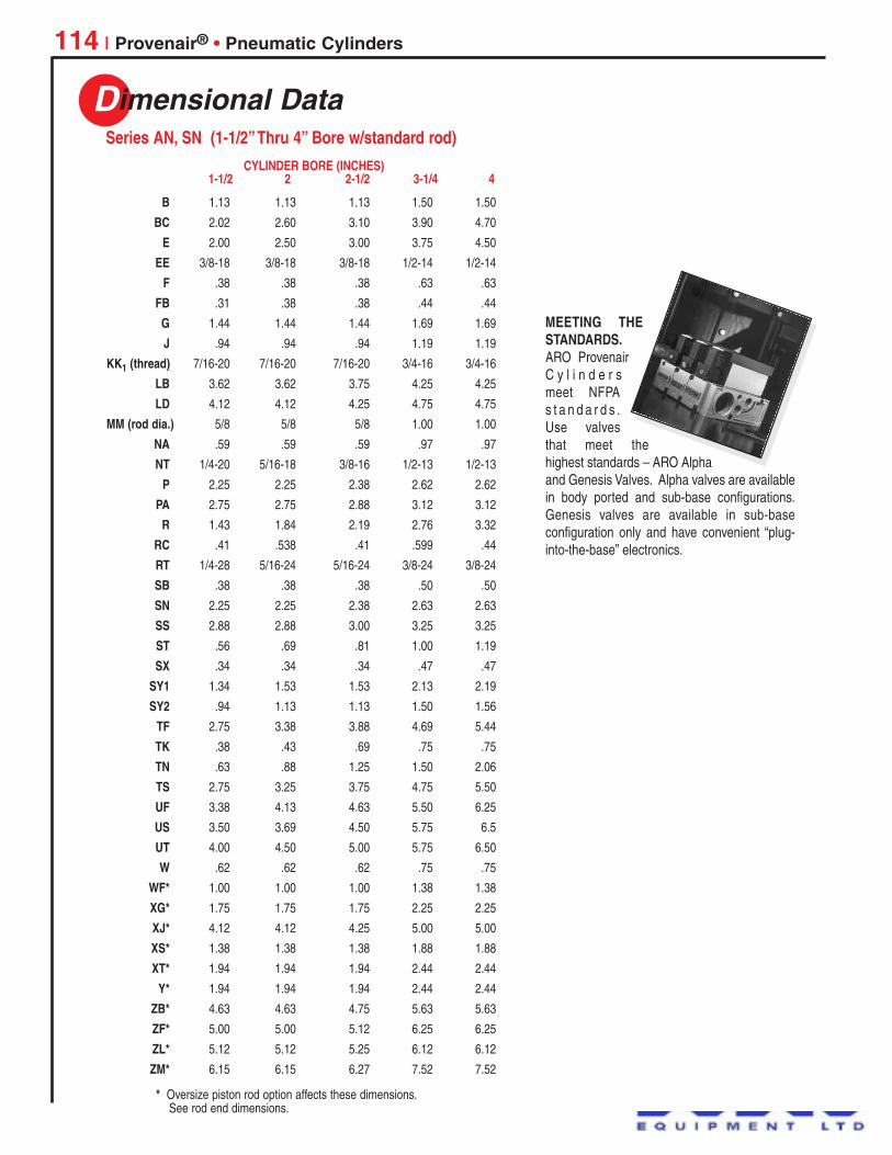
Dimensional DataSeries AN, SN (1-1/2”Thru 4” Bore w/standard rod)
CYLINDER BORE (INCHES)1-1/2 2 2-1/2 3-1/4 4
B 1.13 1.13 1.13 1.50 1.50
BC 2.02 2.60 3.10 3.90 4.70
E 2.00 2.50 3.00 3.75 4.50
EE 3/8-18 3/8-18 3/8-18 1/2-14 1/2-14
F .38 .38 .38 .63 .63
FB .31 .38 .38 .44 .44
G 1.44 1.44 1.44 1.69 1.69
J .94 .94 .94 1.19 1.19
KK1 (thread) 7/16-20 7/16-20 7/16-20 3/4-16 3/4-16
LB 3.62 3.62 3.75 4.25 4.25
LD 4.12 4.12 4.25 4.75 4.75
MM (rod dia.) 5/8 5/8 5/8 1.00 1.00
NA .59 .59 .59 .97 .97
NT 1/4-20 5/16-18 3/8-16 1/2-13 1/2-13
P 2.25 2.25 2.38 2.62 2.62
PA 2.75 2.75 2.88 3.12 3.12
R 1.43 1.84 2.19 2.76 3.32
RC .41 .538 .41 .599 .44
RT 1/4-28 5/16-24 5/16-24 3/8-24 3/8-24
SB .38 .38 .38 .50 .50
SN 2.25 2.25 2.38 2.63 2.63
SS 2.88 2.88 3.00 3.25 3.25
ST .56 .69 .81 1.00 1.19
SX .34 .34 .34 .47 .47
SY1 1.34 1.53 1.53 2.13 2.19
SY2 .94 1.13 1.13 1.50 1.56
TF 2.75 3.38 3.88 4.69 5.44
TK .38 .43 .69 .75 .75
TN .63 .88 1.25 1.50 2.06
TS 2.75 3.25 3.75 4.75 5.50
UF 3.38 4.13 4.63 5.50 6.25
US 3.50 3.69 4.50 5.75 6.5
UT 4.00 4.50 5.00 5.75 6.50
W .62 .62 .62 .75 .75
WF* 1.00 1.00 1.00 1.38 1.38
XG* 1.75 1.75 1.75 2.25 2.25
XJ* 4.12 4.12 4.25 5.00 5.00
XS* 1.38 1.38 1.38 1.88 1.88
XT* 1.94 1.94 1.94 2.44 2.44
Y* 1.94 1.94 1.94 2.44 2.44
ZB* 4.63 4.63 4.75 5.63 5.63
ZF* 5.00 5.00 5.12 6.25 6.25
ZL* 5.12 5.12 5.25 6.12 6.12
ZM* 6.15 6.15 6.27 7.52 7.52
* Oversize piston rod option affects these dimensions.See rod end dimensions.
MEETING THESTANDARDS.ARO ProvenairC y l i n d e r smeet NFPAs t a n d a r d s .Use valvesthat meet thehighest standards – ARO Alphaand Genesis Valves. Alpha valves are availablein body ported and sub-base configurations.Genesis valves are available in sub-baseconfiguration only and have convenient “plug-into-the-base” electronics.
Colin
Logo1
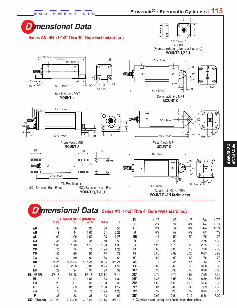
Provenair® • Pneumatic Cylinders | 115
Dimensional DataSeries AN, SN (1-1/2”Thru 10” Bore w/standard rod)
Side End Lugs MS7MOUNT L
Angle Mount MS1MOUNT A
Detachable Eye MP4MOUNT K
Detachable Clevis MP2MOUNT P (AN Series only)
Tie Rod MountsMX1 Extended Both Ends MX3 Extended Head End
MOUNT Q, T & U
ZE + Stroke
SE + StrokeEQ EQ
ET
ET
EE
R
EB, 4 Pl.
WLEL
XE + StrokeZB + Stroke
WL
ZD + Stroke
XD + Stroke
ZC + Stroke
ZD + Stroke
XD + Stroke
ZB + Stroke
XC + Stroke
M
ML
M
CD
CD
CD
LR
LR
LR
CWCB
CW
CW
BB BB R
RDD
CB
EW
MR
MR
MR
FFL
F
FFL
SA + Stroke
AB,HOLE (6)
S
AH
AO.188
AO
XA + Stroke
AL
W
E
▲
▼
RT Thread RC Depth
(Female retaining bolts either end)MOUNTS 1,2,3,4
E
Fixed Clevis MP1MOUNT C
PROVENAIR
CYLINDERS
Dimensional Data
AB .38 .38 .38 .50 .50AH 1.18 1.44 1.62 1.94 2.25AL 1.00 1.00 1.00 1.25 1.25AO .38 .38 .38 .50 .50BB 1.00 1.13 1.13 1.38 1.38CB .75 .75 .75 1.25 1.25CD .50 .50 .50 .75 .75CW .50 .50 .50 .63 .63DD 1/4-28 5/16-24 5/16-24 3/8-24 3/8-24E 2.00 2.50 3.00 3.75 4.50
EB .28 .34 .34 .38 .38EE (NPTF) 3/8-18 3/8-18 3/8-18 1/2-14 1/2-14
EL .75 .94 1.06 .88 1.00EQ .25 .31 .31 .38 .38ET .56 .69 .81 1.00 1.19EW .75 .75 .75 1.25 1.25F .38 .38 .38 .63 .63
KK1 (Thread) 7/16-20 7/16-20 7/16-20 3/4-16 3/4-16
CYLINDER BORE (INCHES)1-1/2 2 2-1/2 3-1/4 4
Series AN (1-1/2”Thru 4” Bore w/standard rod)
FL 1-1/8 1-1/8 1-1/8 1-7/8 1-7/8L 3/4 3/4 3/4 1-1/4 1-1/4
LR 3/4 3/4 3/4 1-1/4 1-1/4M 5/8 5/8 5/8 7/8 7/8
MR .47 .50 .50 .75 .75R 1.43 1.84 2.19 2.76 3.32S 1.25 1.75 2.25 2.75 3.50
SA 6.00 6.00 6.12 7.38 7.38SE 5.50 5.88 6.25 6.63 6.88W* .62 .62 .62 .75 .75WL .14 .33 .45 .13 .25XA 5.62 5.62 5.75 6.88 6.88XC* 5.38 5.38 5.50 6.88 6.88XD* 5.75 5.75 5.88 7.50 7.50XE* 5.38 5.56 5.81 6.50 6.63ZB* 4.63 4.63 4.75 5.63 5.63ZC* 5.84 5.88 6.00 7.63 7.63ZD* 6.22 6.25 6.38 8.25 8.25ZE* 5.63 5.84 6.13 6.88 7.00* Oversize piston rod option affects these dimensions.
Colin
Logo1

116 | Provenair® • Pneumatic Cylinders
Switch Mounting Brackets
Position Sensors (Switches)
Model Number 119581-1 119581-2 119581-3 119582-1 119582-2 119582-3 119583-1 119583-2 119583-3Lead Length/Type 1m bare 3m bare Plug 1m bare 3m bare Plug 1m bare 3m bare PlugLead Color Black Grey BlackSwitch Type REED PNP(SOURCING) NPN (SINKING)Input Voltage 100 VDC, 125 VAC Max. 10 - 30 VDC 5 - 30 VDC
300mA (150mA Inductive) 5 - 100mA @ 5VOperating Current 7 - 100mA @ 12V 10 - 200mA @ 12V
- 14 - 200mA @ 24V 20 - 200mA @ 24VDetecting Distance 2.5 mm 1.5 mm 1.5 mmDetecting Width 3.0 mm 3.0 mmResponse Time 1 mSec. Min.LED Function 18mA Min. 1mA Min. 1mA Min.
Bore Model Number
1-1/2” 119584
2”, 2-1/2” 119585
3-1/4” & 4” 119586
Hall Effect Switches
Reed SwitchesSwitch is normally open, load can be attachedto BROWN or BLUE lead. The BROWN lead isthe higher potential side of the switch. In amagnetic field, the two reeds are brought intocontact to “make” the circuit. Reed switcheshave black, ‘two wire’ leads.
It is important to note that Hall Effect switchesmust always have current through them to work.In a magnetic field, the semiconductor generatesa voltage across the sense leads. Removing themagnetic field returns the switch to its normallyopen state. Hall effect switches have ‘three wire’leads. Black leads are sinking (NPN). Greyleads are sourcing (PNP). Load is controller.
There are two types of Hall Effect switches.Each is connected differently. Check your PLCfor the input method used. Sinking (NPN) willsink current to ground. Sourcing (PNP) willprovide current from the +VDC.
Sinking Sourcing
Mag. Field
N.O.
+DC +DCBROWN
BROWN
BLACK
BLACK
LOADLOAD
BLUE BLUE
NOTE: Operating temperature is 14 - 140o F and theenvironmental rating is IEC IP 67 in all three switchtypes. Std. Red LED requires min 18 mA.
Switch Specifications
CYLINDER BORE (Inches)1 1/2” 2 & 2 1/2” 3 1/4” & 4”
B1 .51 .60 .80B2 1.50 1.77 2.45B3 .26 .26 .33
Colin
Logo1

Provenair® • Pneumatic Cylinders | 117
Dimensional DataSeries AN, SN (5”,6”,8” and 10” Bore)
Tie Rods Extended, Cap End MX2
Flange Head ME3Flange Cap ME4
Tie Rods Extended, Head End MX3
Side Tapped MS4
End Angle MS1
Tie Rods Extended Both Ends MX1
Basic Cylinder Dimensions
EE NPT (2)
FB HOLES (4)
FB HOLES (4)
ZF + STROKE
KK THREADD-WRENCH FLATS
MM ROD DIA. P + STROKE
LB + STROKEZB + STROKE
B BUSHING DIA.
CUSHIONSRM DIA.R
A
JK
R
R
FH
TF
TF
UF
UF
WFH
C GV
Y
E SQ.
XT
AO FH
DD
DD THD
BBBB
BB
DD
BBFH
R
R
R
AA
AA
AA
FH
ATAH
SAB (HOLE)ME
AL AL
TN
E/2
NT TAPTK DEPTH
SN + STROKE
XA + STROKE
SA + STROKE
R
E
FB HOLES (4)EE NPT (2)EE NPT (2)
Cap Rectangular Flange MF2
TEE
Head Rectangular Flange MF1
Get in the
PROVENAIR
CYLINDERS
TE
Colin
Logo1

Dimensional Data
118 | Provenair® • Pneumatic Cylinders
CYLINDER BORE (INCHES)5 5 6 6 8 8 10
ROD 1 1-3/8 1-3/8 1-3/4 1-3/8 1-3/4 1-3/4
A 1.13 1.63 1.63 2.00 1.63 2.00 2.00AA 5.18 5.18 6.90 6.90 9.1 9.1 11.2AB .69 .69 .81 .81 .81 .81 –AH 2.88 2.88 3.25 3.25 4.25 4.25 –AL 1.38 1.38 1.38 1.38 1.81 1.81 –AO .63 .63 .63 .63 .69 .69 –AT .19 .19 .19 .19 .25 .25 –B 1.50 2.00 2.00 2.38 2.00 2.38 2.38
BB 1.81 1.81 1.81 1.81 2.31 2.31 2.69C .50 .63 .63 .75 .63 .75 .75
CB 1.25 1.25 1.50 1.50 1.50 1.50 2.00CD .75 .75 1.00 1.00 1.00 1.00 1.38CW .63 .63 .75 .75 .75 .75 1.00D .81 1.13 1.13 1.50 1.13 1.50 1.50
DD 1/2”-20 1/2”-20 1/2”-20 1/2”-20 5/8”-18 5/8”-18 3/4”-16E 5.50 5.50 6.50 6.50 8.50 8.50 10.63
EE(NPTF) 1/2 1/2 3/4 3/4 3/4 3/4 1.00F .63 .63 .63 .75 .63. .75 .63
FB .56 .56 .56 .56 .69 .69 .81FH .63 .63 .75 .75 – – .63FL 2.13 2.13 2.25 2.25 – – –G 1.75 1.75 2.00 2.00 2.00 2.00 2.25J 1.25 1.25 1.50 1.50 1.50 1.50 2.00K .44 .44 .50 .50 .63 .63 .69
KK1 THREAD 3/4-16 1-14 1-14 1-1/4-12 1-14 1-1/4-12 1-1/4-12L 1.25 1.25 1.50 1.50 1.50 1.50 2.13
LB 4.25 4.25 5.00 5.00 5.13 5.13 6.38LD 4.75 4.75 5.50 5.50 5.63 5.63 6.63M .88 .88 1.00 1.00 1.00 1.00 1.38
MM 1 1-3/8 1-3/8 1-3/4 1-3/8 1-3/4 1-3/4NT 5/8”-11 5/8”-11 3/4”-10 3/4”-10 3/4”-10 3/4”-10 1-8P 2.63 2.63 3.00 3.00 3.13 3.13 4.31R 4.10 4.10 4.88 4.88 7.57 7.57 7.92
RM 2.63 3.38 3.38 3.50 3.38 3.50 3.50S 4.25 4.25 5.25 5.25 7.13 7.13 7.13
SA 7.63 7.63 8.50 8.50 8.75 8.75 –SN 2.88 2.88 3.13 3.13 3.25 3.25 4.13TD 1.00 1.00 1.38 1.38 1.38 1.38 –TE – – – – 7.57 7.57 9.40TF 6.63 6.63 7.63 7.63 7.57* 7.57* –TK 1.00 1.00 1.13 1.13 1.13 1.13 1.50TL 1.00 1.00 1.38 1.38 1.38 1.38 –TN 2.69 2.69 3.25 3.25 4.50 4.50 5.50UF 7.63 7.63 8.63 8.63 – – –UT 7.50 7.50 9.25 9.25 11.25 11.25 –V .25 .38 .38 .38 .38 .38 .50W .75 1.00 .88 1.13 1.63 1.88 1.88XA 7.00 7.25 8.00 8.25 8.56 8.81 –XC 6.88 7.13 8.13 8.38 8.25 8.50 10.38XD 7.75 8.00 8.88 9.13 – – –XG 2.25 2.50 2.63 2.88 2.63 2.88 –XJ 5.00 5.25 5.88 6.13 6.00 6.25 –XT 2.31 2.56 2.81 3.06 2.81 3.06 3.13Y 2.44 2.44 2.88 2.88 2.88 2.88 3.00
ZB 6.06 6.31 7.13 7.38 7.38 7.63 8.94ZF 6.50 6.75 7.38 7.63 6.75 7.00 8.25ZM 7.75 8.25 8.75 9.25 8.88 9.38 10.63
Detachable Clevis MP2(Not available on 6 or 8-inch bore)
Fixed Clevis MP1
CB
FLCW CW
L M
L M
XC + STROKE
XD + STROKE
CD DIA.
CBCW CW
Cap Rectangular Flange MF2
Head Trunnion MT1
Cap Trunnion MT2
TD
TD
UTXG CUSHIONS
CUSHIONSXJ + STROKE
TL TL
UTTL TL
Double Rod End
REE
A
VV
C
F
G G
A
Y
RM DIA.
KK THD.
EE NPT (2)
P + STROKE
CUSHIONS
LD + STROKE
ZM + 2X STROKE
B BUSHING DIA.
MM ROD DIA.
F
Provenair MountsSeries AN, SN (5”, 6”, 8”, & 10” Bore)
Colin
Logo1

Dimensional Data
Provenair® • Pneumatic Cylinders | 119
Accessories
BA - 2.56 3.25 -CB - 1.25 1.50 -CD - .75 1.00 -CW - .63 .75 -
DD DIA. - .53 .66 -DD TAP - 1/2-20 5/8-18 -
E - 3.50 4.50 -F - .63 .75 -
FL - 1.88 2.25 -M - .75 1.00 -
Clevis Bracket (Iron) – 117206-5 117206-6 –
Eye Bracket (Iron) – 117205-5 117205-6 –
ROD THREAD7/16-20 3/4-16 1-14 1-1/4-12
ROD CLEVIS KIT 116183 116046 116049 116052(includes pin)ROD EYE KIT 116184 116047 116050 116053CLEVIS PIN 115299 115300 – –PIVOT PIN – – 116048 116051
KK1 7/16”-20 x 3/4” 3/4”-16 x 1-1/8” 1”-14 x 1-1/8” -117812-101 117812-201 117812-301
KK1 (2 x length) 7/16”-20 x 1-1/2” 3/4”-16 x 2-1/4” 1”-14 x 2-1/4” -117812-121 117812-221 117812-321
KK2 (1st oversize) 1/2”-20 x 3/4” 7/8”-14 x 1-1/8” 1-1/4”-12 x 1-5/8” -117812-102 117812-202 117812-302
CC Full (2nd oversize) 5/8”-18 x 3/4” 1”-14 x 1-1/8” 1-3/8”-12 x 1-5/8” -117812-103 117812-203 117812-303
ROD DIAMETER (INCHES)5/8 1 1-3/8 1-3/4
Stud Thread Stud Thread Stud ThreadPart Number Part Number Part Number
A .75 1.13 1.63 2.00CA 1.50 2.06 2.81 3.44CB .75 1.25 1.50 2.00CD .50 .75 1.00 1.38CD1 .44 .75 – –CE 1.50 2.38 3.13 4.13CH 1.00 1.25 1.50 2.00CW .50 .63 .75 1.00ER .72 1.06 1.00 1.38HP .156 .156 – –KK1 7/16-20 3/4-16 1-14 1 1/4-12
L .75 1.25 1.50 2.13LH 2.25 3.13 3.75 5.00LP 2.1 2.75 3.25 4.50
Rod Eye, Rod Clevis and Pin
Series AN (5/8 “ thru 1-3/4” Rod)
Socket Head Rod Studs
Mating parts to rod end accessories and mounting brackets
Mating parts to rod end accessories and mounting brackets
Pivot Pin
Use for Both Pins
Clevis Pin
Eye Bracket*
Clevis Bracket*
LP LP
LH
BA
CW CW
F
FL
M RAD.
CD HOLE
CB
BA
DD TAP
E SQ.
BA
F
FL
M RAD.
CD HOLE
CB
BA
DD DIA.
E SQ.
CD
HPLH
* These accessory brackets attach to matingcylinder mounts. See Cylinder MountingDimensions on page 118.
Rod Clevis
CA
CD
CE
KK1
CD
CWCWCB
CH(across flats)
L
KK1 Thread
CB
A
ER
CD1
CD CDRod Eye
PROVENAIR
CYLINDERS
Colin
Logo1

120 | Provenair® • Pneumatic Cylinders
Ordering
Q 1- 1/2”S 2”T 2- 1/2”
W 3-1/4”4 4”
ACTUATORSAll actuators begin with ASERIES (N)All Provenair Cylindersare Series N
Two Provenair tank styles provide unique capabilities for your applications.Style A, air-over-oil tanks provide the smooth control hydraulic systems are knownfor, without the expense, using shop air.
Style T reservoirs provide a supply of air near the point of use, allowing your systemto use a smaller compressor or smaller system supply lines.
SEALS
SIGHT GLASS LOCATION
PORT LOCATION MS4 mounts: Port locations other than “A”, call factory.
MOUNT
0 = 0 in1 = 1/8 in2 = 1/4 in3 = 3/8 in4 = 1/2 in5 = 5/8 in6 = 3/4 in7 = 7/8 in
Include dashes ( - ). Dashes are significant.
ENTER X IN THIS POSITION
BORE SIZE
TYPET Tank
STROKE
Inches
Tens0-9
0-9
Ones
Fractions
B Buna-N V Viton
(X must be used with Tank Style T)
A H1, C1(Std.)
B H1, C2D H1, C4
F H2, C1G H2, C2
J H2, C4U H4, C4
A MS1 B MS4 L MS7 X No Mount
X = None A = 1 B = 2 C = 4
N XTA
NOTE:Maximum stroke 99 7/8”, forlonger strokes consult factory.Style TMinimum stroke 2”.Style ANote: Sight glass (required)Minimum 5” stroke. 4 2
1
Determine port and sightglass locations looking at
top of tank.
Air/Oil Tank
Air Reservoir
Bore Style A Style TQ 1-1/2” 1.33 1.77S 2” 2.36 3.14T 2-1/2” 3.68 4.91W 3-1/4” 6.22 8.294 4” 9.42 12.56
Useable Volume Finder
Typical Air Oil CircuitBORE A J TN E EE NPTF
Q 1-1/2” 2.005 0.94 0.63 2 3/8-18S 2” 2.005 0.94 0.88 2.5 3/8-18T 2-1/2” 2.005 0.94 1.25 3 3/8-18W 3-1/4” 2.505 1.19 1.5 3.75 1/2-144 4” 2.505 1.19 2.06 4.5 1/2-14
TANK DIMENSIONS
EE (N
PTF)
E
E
EE TN
JJ
A +
STRO
KE
Sight glass availablein Style A only
250 P.S.I.
Fill Portavailablein StyleA only
TANK STYLEA Air / Oil T Air Reservoir
Tanks & Reservoirs (1-1/2” thru 4” Bore)
Style T or ADerive required circuit volume (V) in Cu. In.
Divide (V) by factor from chart above to determinestroke (enter stroke value into model number).
Find unit length by adding stroke to dimensionA from tank dimension table.
Colin
Logo1

Repair Kits • Pneumatic Cylinders | 121
Ordering
Rod Diameter 5/8 5/8 1 5/8 1 1 1-3/8 1 1-3/8Series AN Bushing 119454 119455 119456 119455 119456 119457 119458 119457 119458Series SN Bronze Bushing 114171 114171 114172 114171 114172 114172 114173 114172 114173
7150 7151 7152
CYLINDER BORE SIZE (INCHES)1-1/2 2 2 2-1/2 2-1/2 3-1/4 3-1/4 4 4
BORE SIZE 1/2 3/4 1-1/8
Order two kits for doublerod end cylinders.
Rod Diameter - 1 1-3/8 1-3/8 1-3/4 1-3/8 1-3/4 1-3/4 2Series AN Bushing - 115074 115075 115075 115076 115075 115076 115076 114130Series SN Bronze Bushing - 114172 114173 114172 114173 114173 114174 114174 114175
CYLINDER BORE SIZE (INCHES)5 5 6 6 8 8 10 10
Repair Kits (Single Rod End Rod Bushings)
Seal Kits (Economair Series)
Reciprocating Assembly (Economair Series)
Micro-Air Series 01 (Seal Kits)
To order a repair kit, 1) Obtain model numberfrom label on cylinder. 2) Write “RK” for RepairKit and 3) Using number from cylinder label,construct proper kit number as directed below.
Cylinder Model Number
EXAMPLE: 28 20 - 5 3 09-040
Order Kit No.:
RK 24 20 - 1 3
For AllModelsWritein RK
SERIES NUMBERIf 23, (Noncushion), write 23If 24 (Cushion), 27 (Cushion, Pin Actuated), or 28 (Cushion, Magnetic) write 24
BORE SIZETake bore size from model number:18, 15, 20, 25, 30 or 40.
CYLINDER TYPEIf 1, 3, 4, 5, 6, or 7, write 1.
If 2, write 2.
PACKINGTake packing identifier from modelnumber: 0, 2, 3, 4, 5, 6, or 8
Only these numbers are used.
Cylinder Model Number
EXAMPLE: 28 20 - 2 3 8 9-040
Order Assembly No.:
RA 24 20 - 2 0 8 - X X X
To order a reciprocating assembly, 1) Obtain model numberfrom label on cylinder. 2) Write “RA” for reciprocatingassembly and 3) Using number from cylinder label,construct proper assembly number as directed below.
For AllModelsWritein RA SERIES NUMBER
If 23, (Noncushion), write 23If 24 (Cushion), 27 (Cushion, Pin Actuated), write 24If 25 (Bumper) or 29 (Bumper, Magnetic), write 25If 28 (Magnetic), write 28
BORE SIZETake bore size from modelnumber: 18, 15, 20, 25, 30 or 40.
CYLINDER TYPEIf 1, 3, 4, 5, 6, or 7, write 1.
If 2, write 2.
PACKINGTake packing identifier from modelnumber: if 0 or 3 write 0
if 2, write 2if 4, 5 or 6 write 4
ROD MATERIALPACKING0 Standard Chrome8 Stainless Steel
STROKE
Only these numbers are used.
EXAMPLE RECIPROCATING ASSEMBLY MODEL NUMBER:R A 2 4 2 0 - 2 0 8 - 0 4 0
Supplies a stainless steel rod with 2” O-ring piston fora double rod end, 4” stroke.
REPAIR KITS
Colin
Logo1
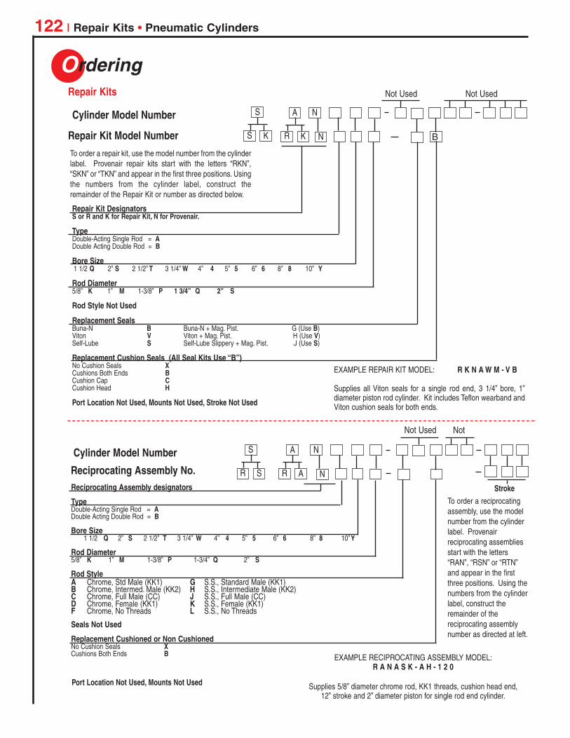
Ordering
122 | Repair Kits • Pneumatic Cylinders
R K N
Repair Kit DesignatorsS or R and K for Repair Kit, N for Provenair.
TypeDouble-Acting Single Rod = ADouble Acting Double Rod = B
Bore Size1 1/2 Q 2” S 2 1/2” T 3 1/4” W 4” 4 5” 5 6” 6 8” 8 10” Y
Rod Diameter5/8” K 1” M 1-3/8” P 1 3/4” Q 2” S
Rod Style Not Used
Replacement SealsBuna-N B Buna-N + Mag. Pist. G (Use B)Viton V Viton + Mag. Pist. H (Use V)Self-Lube S Self-Lube Slippery + Mag. Pist. J (Use S)
Replacement Cushion Seals (All Seal Kits Use “B”)No Cushion Seals XCushions Both Ends BCushion Cap CCushion Head H
Port Location Not Used, Mounts Not Used, Stroke Not Used
B
To order a repair kit, use the model number from the cylinderlabel. Provenair repair kits start with the letters “RKN”,“SKN” or “TKN” and appear in the first three positions. Usingthe numbers from the cylinder label, construct theremainder of the Repair Kit or number as directed below.
EXAMPLE REPAIR KIT MODEL: R K N A W M - V B
Supplies all Viton seals for a single rod end, 3 1/4” bore, 1”diameter piston rod cylinder. Kit includes Teflon wearband andViton cushion seals for both ends.
NA
Repair Kit Model Number S K
S
Not Used Not UsedRepair Kits
Cylinder Model Number
Reciprocating Assembly designators
TypeDouble-Acting Single Rod = ADouble Acting Double Rod = B
Bore Size1 1/2 Q 2” S 2 1/2” T 3 1/4” W 4” 4 5” 5 6” 6 8” 8 10”Y
Rod Diameter5/8” K 1” M 1-3/8” P 1-3/4” Q 2” S
Rod Style A Chrome, Std Male (KK1) G S.S., Standard Male (KK1)B Chrome, Intermed. Male (KK2) H S.S., Intermediate Male (KK2)C Chrome, Full Male (CC) J S.S., Full Male (CC)D Chrome, Female (KK1) K S.S., Female (KK1)F Chrome, No Threads L S.S., No Threads
Seals Not Used
Replacement Cushioned or Non CushionedNo Cushion Seals XCushions Both Ends B
To order a reciprocatingassembly, use the modelnumber from the cylinderlabel. Provenairreciprocating assembliesstart with the letters“RAN”, “RSN” or “RTN”and appear in the firstthree positions. Using thenumbers from the cylinderlabel, construct theremainder of thereciprocating assemblynumber as directed at left.
EXAMPLE RECIPROCATING ASSEMBLY MODEL:R A N A S K - A H - 1 2 0
Supplies 5/8” diameter chrome rod, KK1 threads, cushion head end,12” stroke and 2” diameter piston for single rod end cylinder.
R A N
NACylinder Model Number
Reciprocating Assembly No.
Not Used Not
Port Location Not Used, Mounts Not Used
Stroke
R S
S
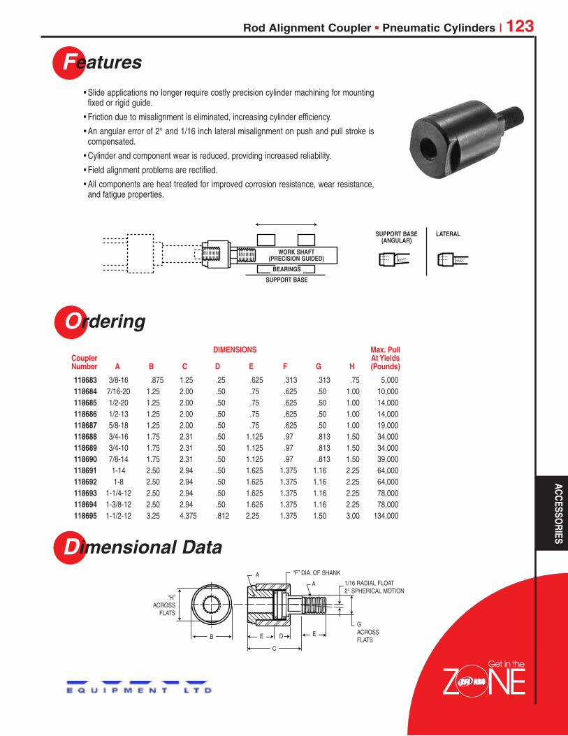
Get in the
Features
Rod Alignment Coupler • Pneumatic Cylinders | 123
Dimensional Data
Ordering
• Slide applications no longer require costly precision cylinder machining for mountingfixed or rigid guide.
• Friction due to misalignment is eliminated, increasing cylinder efficiency.
• An angular error of 2° and 1/16 inch lateral misalignment on push and pull stroke iscompensated.
• Cylinder and component wear is reduced, providing increased reliability.
• Field alignment problems are rectified.
• All components are heat treated for improved corrosion resistance, wear resistance,and fatigue properties.
WORK SHAFT(PRECISION GUIDED)
BEARINGS
SUPPORT BASE
SUPPORT BASE(ANGULAR)
LATERAL
“H”ACROSS
FLATS
GACROSSFLATSB
C
E E
AA
“F” DIA. OF SHANK
1/16 RADIAL FLOAT2° SPHERICAL MOTION
D
118683 3/8-16 .875 1.25 .25 .625 .313 .313 .75 5,000118684 7/16-20 1.25 2.00 .50 .75 .625 .50 1.00 10,000118685 1/2-20 1.25 2.00 .50 .75 .625 .50 1.00 14,000118686 1/2-13 1.25 2.00 .50 .75 .625 .50 1.00 14,000118687 5/8-18 1.25 2.00 .50 .75 .625 .50 1.00 19,000118688 3/4-16 1.75 2.31 .50 1.125 .97 .813 1.50 34,000118689 3/4-10 1.75 2.31 .50 1.125 .97 .813 1.50 34,000118690 7/8-14 1.75 2.31 .50 1.125 .97 .813 1.50 39,000118691 1-14 2.50 2.94 .50 1.625 1.375 1.16 2.25 64,000118692 1-8 2.50 2.94 .50 1.625 1.375 1.16 2.25 64,000118693 1-1/4-12 2.50 2.94 .50 1.625 1.375 1.16 2.25 78,000118694 1-3/8-12 2.50 2.94 .50 1.625 1.375 1.16 2.25 78,000118695 1-1/2-12 3.25 4.375 .812 2.25 1.375 1.50 3.00 134,000
DIMENSIONS Max. PullCoupler At YieldsNumber A B C D E F G H (Pounds)
ACCESSORIES
Colin
Logo1

Get in the
Features
124 | Air Systems Components
Proper conditioning of compressed air is essential to ensure maximumperformance and service life for pneumatic power tools and equipment. Thesmall initial investment for installation of air preparation units in an air linesystem will pay long-term dividends in increased productivity, consistent qualityand decreased maintenance costs.Ingersoll-Rand’s extensive line of air line filters, regulators and lubricators,including individual units, piggyback and combos, have been designed to meetevery air preparation requirement.
Ingersoll-Rand compressed air filters are designed to remove airborne solidand liquid contaminates which may plug small orifices and hinder performance,or cause excessive wear and premature equipment failure. Several filterelements are offered, including models with coalescing elements for removal ofoil aerosols and particles down to .3 micron.
• Available pipe sizes from 1/8” thru 2” NPT
Filters
Ingersoll-Rand air line regulators provide controlled, consistent air pressure asrequired for specific pneumatic equipment when connected to the completecompressed air system.
• Available pipe sizes from 1/8” thru 1-1/2” NPT• Flows to 440 CFM• Maximum Inlet pressures to 250 PSIG
Regulators
When selecting an FRL or individual filter, regulator and lubricator units, the airconsumption of the tools or equipment to be serviced should be correlated withthe flow capacity of the FRL. Please reference flow capacity chart below.
F-R-L Product Selection
Net FLOW CAPACITY (CFM) PressurePort Filter Filter Piggy Range
Series Size (Particulate) (Coalescing) Regulator Back Lubricator PSIGModule 1/8” 28 15 13 12 41 0-125Air 1000 1/4” 38 17 13 12 60 0-125Module/ 1/4” 54 40 100 93 75 0-200Air 2000 3/8” 100 51 135 135 100 0-200
1/2” 122 53 140 140 110 0-200Super-Duty 3/4” 345 50 180 – 150 0-250
1” 345 150 200 – 300 0-250
C28121-800
C28221-810
C28453-810
Colin
Logo1

Air Systems Components | 125
Ordering
Accessories
Designed to remove rust, scale, condensed water and other debris from compressedair lines which may cause wear and premature failure of tools, valves, cylinders andother penumatic equipment.
Standard Filters
1/8” & 1/4” Port - ARO Module/Air 1000 Series1/8” F25111-200 20 Micron 28 Polycarbonate/Guard 1.0 oz. Manual 200 PSIG1/4” F25121-200 20 Micron 38 Polycarbonate/Guard 1.0 oz. Manual 200 PSIG1/4” & 3/8” & 1/2” Port - ARO Module/Air 2000 Series1/4” F25221-110 40 Micron 54 Metal w/sight glass 6.0 oz. Manual 175 PSIG3/8” F25231-110 40 Micron 100 Metal w/sight glass 6.0 oz. Manual 175 PSIG1/2” F25241-110 40 Micron 122 Metal w/sight glass 6.0 oz. Manual 175 PSIG3/4” & 1” Port - ARO Super-Duty Series3/4” F25451-110 40 Micron 345 Metal w/sight glass 32 oz. Manual 250 PSIG1” F25461-110 40 Micron 345 Metal w/sight glass 32 oz. Manual 250 PSIG
* Air Flow is at 90 PSI Inlet and 5 PSI pressure drop.
Designed for paint spraying, instrumentation, controls and other applications where thedelivered air must be free of oil and fine particles. Effective in removing 99.9% of oilaerosols. Also effective in removing debris particles down to .3 micron.Recommended for use in conjunction with an upstream filter to maximize the life ofreplacement element.
Coalescing Filters
1/8” & 1/4” Port - ARO Module/Air 1000 Series1/8” F25111-300 Coalescing 15 Polycarbonate 1.0 oz. Manual 200 PSIG1/4” F25121-300 Coalescing 17 Polycarbonate 1.0 oz. Manual 200 PSIG1/4” & 3/8” & 1/2” Port - ARO Module/Air 2000 Series1/4” F25221-310 Coalescing 40 Metal w/sight glass 6.0 oz. Manual 175 PSIG3/8” F25231-310 Coalescing 51 Metal w/sight glass 6.0 oz. Manual 175 PSIG1/2” F25241-310 Coalescing 53 Metal w/sight glass 6.0 oz. Manual 175 PSIG3/4” & 1” Port - ARO Super-Duty Series3/4” F25452-310 Coalescing 50 Metal w/sight glass 32 oz. Manual 250 PSIG1” F25462-310 Coalescing 150 Metal w/sight glass 32 oz. Manual 250 PSIG
* Air Flow is at 90 PSI Inlet and 5 PSI pressure drop.
Port Filter Flow* Bowl Max. InletSize Model Element cfm Bowl Size Drain Pressure
ARO Module/Air 1000 Series29660-2 20 Micron Element29586 Coalescing Element104257 Service Kit104264 Auto Drain Kit104258 Polycarbonate Bowl104259 Composite Bowl
ARO Module/Air 2000 Series100031-1 40 Micron Element100032 Coalescing Element104068 Auto Drain Kit104204 Metal w/sight glass104176 Service KitARO Super/Duty Series104119 40 Micron Element10423 Coalescing Element104116 Service Kit104068 Auto Drain104163 Sight Glass Kit
F25121-200
F25221-110
F25451-020
Port Filter Flow* Bowl Max. InletSize Model Element cfm Bowl Size Drain Pressure
Part Number Description Part Number Description
AIR LINECO
MPO
NENTS
Colin
Logo1
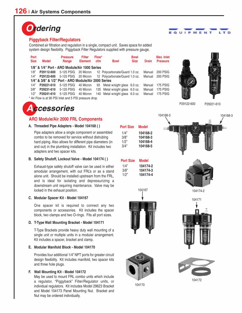
104172
Accessories
126 | Air Systems Components
104170
P29122-600 P29221-610
Ordering
Combined air filtration and regulation in a single, compact unit. Saves space for addedsystem design flexibility. Piggyback Filter Regulators supplied with pressure gauge.
Piggyback Filter/Regulators
ARO Module/Air 2000 FRL Components
1/8” & 1/4” Port - ARO Module/Air 1000 Series1/8” P29112-600 5-125 PSIG 20 Micron 12 Polycarbonate/Guard 1.0 oz. Manual 200 PSIG1/4” P29122-600 5-125 PSIG 20 Micron 12 Polycarbonate/Guard 1.0 oz. Manual 200 PSIG1/4” & 3/8” & 1/2” Port - ARO Module/Air 2000 Series1/4” P29221-610 5-125 PSIG 40 Micron 93 Metal w/sight glass 6.0 oz. Manual 175 PSIG3/8” P29231-610 5-125 PSIG 40 Micron 135 Metal w/sight glass 6.0 oz. Manual 175 PSIG1/2” P29241-610 5-125 PSIG 40 Micron 140 Metal w/sight glass 6.0 oz. Manual 175 PSIG
* Air Flow is at 90 PSI Inlet and 5 PSI pressure drop.
Port Pressure Filter Flow* Bowl Max. InletSize Model Range Element cfm Bowl Size Drain Pressure
A. Threaded Pipe Adapters - Model 104168 ( )
Pipe adapters allow a single component or assembledcombo to be removed for service without distrubinghard piping. Also allows for different pipe diameters (inand out) in the plumbing installation. Kit includes twoadapters and two spacer kits.
B. Safety Shutoff, Lockout Valve - Model 104174 ( )
Exhaust-type safety shutoff valve can be used in eitheramodular arrangement, with out FRL’s or as a standalone unit. Should be installed upstream from the FRL,and is ideal for isolating and depressurizing adownstream unit requiring maintenance. Valve may belocked in the exhaust position.
C. Modular Spacer Kit - Model 104167
One spacer kit is required to connect any twocomponents or accessories. Kit includes the spacerblock, two clamps and two O-rings. Fits all port sizes.
D. T-Type Wall Mounting Bracket - Model 104171
T-Type Brackets provide heavy duty wall mounting of asingle unit or multiple units in a modular arrangement.Kit includes a spacer, bracket and clamp.
E. Modular Manifold Block - Model 104170
Provides four additional 1/4” NPT ports for greater circuitdesign flexibility. Kit includes manifold, two spacer kitsand three hole plugs.
F. Wall Mounting Kit - Model 104172May be used to mount FRL combo units which includea regulator, “Piggyback” Filter/Regulator units, orindividual regulators. Kit includes Model 29623 Bracketand Model 104173 Panel Mounting Nut. Bracket andNut may be ordered individually.
1/4” 104168-23/8” 104168-31/2” 104168-43/4” 104168-5
Port Size Model
Port Size Model
1/4” 104174-23/8” 104174-31/2” 104174-4
104168-3 104168-3
104174-2104167
104171
Colin
Logo1
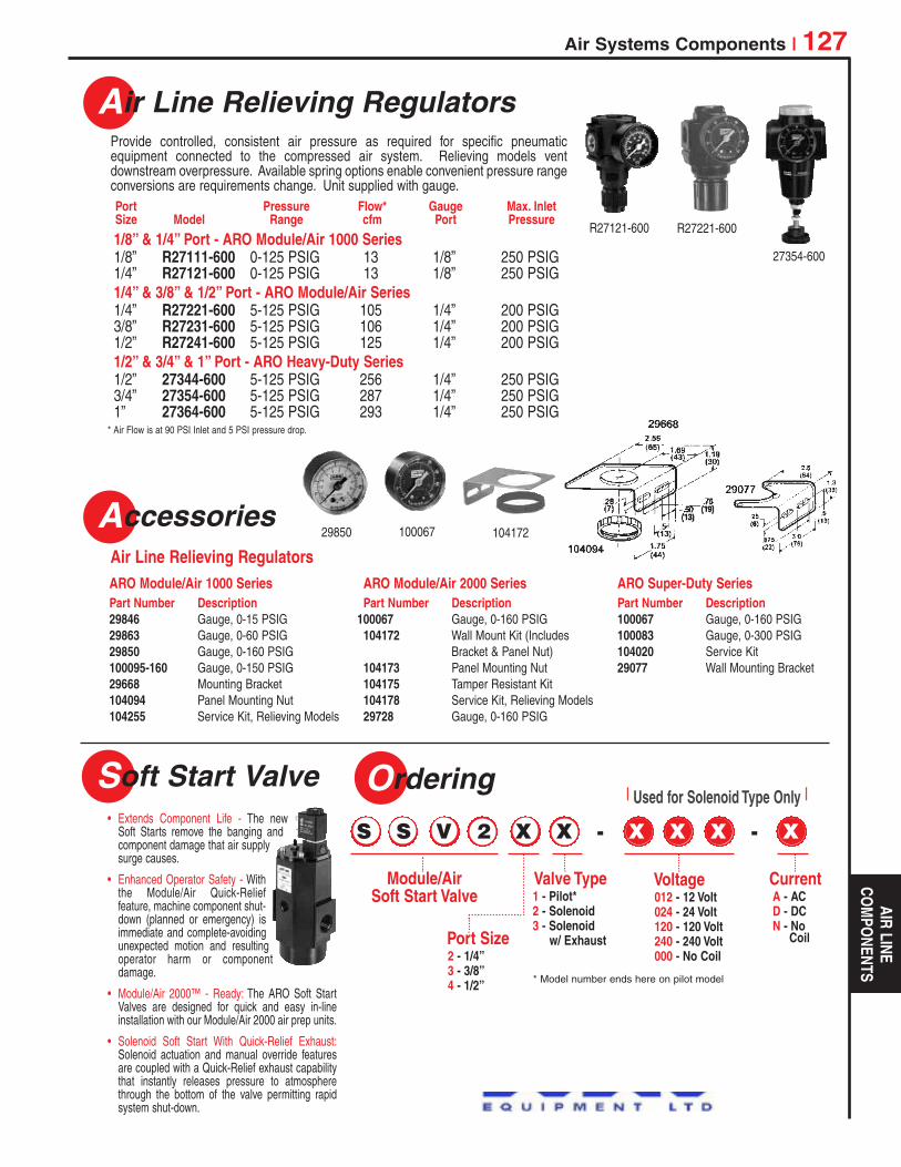
Air Systems Components | 127
Air Line Relieving Regulators
Accessories
Provide controlled, consistent air pressure as required for specific pneumaticequipment connected to the compressed air system. Relieving models ventdownstream overpressure. Available spring options enable convenient pressure rangeconversions are requirements change. Unit supplied with gauge.
Air Line Relieving Regulators
Port Pressure Flow* Gauge Max. InletSize Model Range cfm Port Pressure
10006729850
R27121-600 R27221-600
27354-600
AIR LINECO
MPO
NENTS
104172
ARO Module/Air 1000 SeriesPart Number Description29846 Gauge, 0-15 PSIG29863 Gauge, 0-60 PSIG29850 Gauge, 0-160 PSIG100095-160 Gauge, 0-150 PSIG29668 Mounting Bracket104094 Panel Mounting Nut104255 Service Kit, Relieving Models
ARO Module/Air 2000 SeriesPart Number Description
100067 Gauge, 0-160 PSIG104172 Wall Mount Kit (Includes
Bracket & Panel Nut)104173 Panel Mounting Nut104175 Tamper Resistant Kit104178 Service Kit, Relieving Models29728 Gauge, 0-160 PSIG
ARO Super-Duty SeriesPart Number Description100067 Gauge, 0-160 PSIG100083 Gauge, 0-300 PSIG104020 Service Kit29077 Wall Mounting Bracket
• Extends Component Life - The newSoft Starts remove the banging andcomponent damage that air supplysurge causes.
• Enhanced Operator Safety - Withthe Module/Air Quick-Relieffeature, machine component shut-down (planned or emergency) isimmediate and complete-avoidingunexpected motion and resultingoperator harm or componentdamage.
• Module/Air 2000™ - Ready: The ARO Soft StartValves are designed for quick and easy in-lineinstallation with our Module/Air 2000 air prep units.
• Solenoid Soft Start With Quick-Relief Exhaust:Solenoid actuation and manual override featuresare coupled with a Quick-Relief exhaust capabilitythat instantly releases pressure to atmospherethrough the bottom of the valve permitting rapidsystem shut-down.
Soft Start Valve Ordering
S S V 2 X X - X X X - X
Module/AirSoft Start Valve
Port Size2 - 1/4”3 - 3/8”4 - 1/2”
Valve Type1 - Pilot*2 - Solenoid3 - Solenoid
w/ Exhaust
Voltage012 - 12 Volt024 - 24 Volt120 - 120 Volt240 - 240 Volt000 - No Coil
CurrentA - ACD - DCN - No
Coil
| Used for Solenoid Type Only |
* Model number ends here on pilot model
1/8” & 1/4” Port - ARO Module/Air 1000 Series1/8” R27111-600 0-125 PSIG 13 1/8” 250 PSIG1/4” R27121-600 0-125 PSIG 13 1/8” 250 PSIG1/4” & 3/8” & 1/2” Port - ARO Module/Air Series1/4” R27221-600 5-125 PSIG 105 1/4” 200 PSIG3/8” R27231-600 5-125 PSIG 106 1/4” 200 PSIG1/2” R27241-600 5-125 PSIG 125 1/4” 200 PSIG1/2” & 3/4” & 1” Port - ARO Heavy-Duty Series1/2” 27344-600 5-125 PSIG 256 1/4” 250 PSIG3/4” 27354-600 5-125 PSIG 287 1/4” 250 PSIG1” 27364-600 5-125 PSIG 293 1/4” 250 PSIG
* Air Flow is at 90 PSI Inlet and 5 PSI pressure drop.
Colin
Logo1
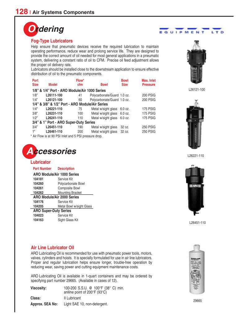
Accessories
128 | Air Systems Components
Lubricator
Ordering
Help ensure that pneumatic devices receive the required lubrication to maintainoperating performance, reduce wear and prolong service life. They are designed toprovide the correct amount of oil needed for most general applications in a pneumaticsystem, delivering a constant ratio of oil to CFM. Precise oil feed adjustment allowsthe proper oil delivery rate.Lubricators should be installed close to the downstream application to ensure effectivedistribution of oil to the pneumatic components.
Fog-Type Lubricators
ARO Lubricating Oil is recommended for use with pneumatic power tools, motors,valves, cylinders and hoists. It is specially formulated for use in air line lubricators.Proper and regular lubrication helps ensure longer, trouble-free operation byreducing wear, saving power and cutting equipment maintenance costs.
ARO Lubricating Oil is available in 1-quart containers and may be ordered byspecifying part number 29665. (Available in cases of 12).
Air Line Lubricator Oil
1/8” & 1/4” Port - ARO Module/Air 1000 Series1/8” L26111-100 41 Polycarbonate/Guard 1.0 oz. 200 PSIG1/4” L26121-100 60 Polycarbonate/Guard 1.0 oz. 200 PSIG1/4” & 3/8” & 1/2” Port - ARO Module/Air Series1/4” L26221-110 75 Metal w/sight glass 6.0 oz. 175 PSIG3/8” L26231-110 100 Metal w/sight glass 6.0 oz. 175 PSIG1/2” L26241-110 110 Metal w/sight glass 6.0 oz. 175 PSIG3/4” & 1” Port - ARO Super-Duty Series3/4” L26451-110 190 Metal w/sight glass 32 oz. 250 PSIG1” L26461-110 200 Metal w/sight glass 32 oz. 250 PSIG
* Air Flow is at 90 PSI Inlet and 5 PSI pressure drop.
Port Flow* Bowl Max. InletSize Model cfm Bowl Size Pressure
ARO Module/Air 1000 Series104181 Service Kit104260 Polycarbonate Bowl104261 Composite Bowl104262 Mounting BracketARO Module/Air 2000 Series104176 Service Kit104205 Metal Bowl w/sight GlassARO Super-Duty Series104023 Service Kit104163 Sight Glass Kit
Viscosity: 100-200 S.S.U. @ 100°F (38° C) min.aniline point of 200°F (93°C)
Class: II LubricantApprox. SEA No: Light SAE 10, non-detergent.
L26121-100
L26451-110
29665
Part Number Description
L26221-110
Colin
Logo1

Get in the
5 Year Warranty
Accessories
Air Systems Components • Accessories/Warranty | 129
Safety Blow Guns are designed to prevent pressure buildup above 29 PSIG if the nozzleis obstructed which meets OSHA requirement 29 CFR1910.242 (b).
OSHA Approved Safety Blow Guns
Composite 8440 Standard Lever 180 PSI 32° to 175° F 1/4” 2.7 oz.Metal 8451-1 Standard Lever 180 PSI 32° to 175° F 1/4” 2.7 oz.
Max. Inlet Temperature InletBody Model Tip Throttle Pressure Range NPT Weight
Compact, rugged balancer features center-pull design for smooth performance.Adjustable spring tension to accommodate weight of suspended equipment. Adjustablecable clamp sets length of travel. Ideal for use with small to medium power tools, smallfixtures, pendent stations and air hoses.
Tool Suspension Balancer
7472 3 to 5 lbs. 8.0 ft. 10.5 in. 5.4 in.7072 6 to 10 lbs. 8.0 ft. 14.0 in. 8.1 in.7072-15 11 to 15 lbs. 8.0 ft. 14.0 in. 8.1 in.
Working DimensionsModel Capacity Cable Length Hook to Hook Width
IR/ARO warrants to the user purchaser of the ARO products depicted in this catalog that the products be freeof defects in material and workmanship for a period of five (5) years from the date of purchase.
ARO will repair or replace, at its election, any product which is found upon its inspection to be defective duringthe period prescribed above. The product must be shipped prepaid to ARO factory or ARO Customer ServiceCenter together with proof of purchase.
This warranty does not apply to failures or defects occurring as a result of abuse, misuse, negligent repairs,corrosion, erosion and normal wear and tear.
THIS WARRANTY IS IN LIEU OF ALL OTHER WARRANTIES (EXCEPT TITLE), EXPRESSED OR IMPLIED,AND THERE ARE NO WARRANTY OF MERCHANTABILITY OR FITNESS FOR PARTICULAR PURPOSE ISINTENDED OR MADE .
THE REMEDIES OF THE USER PURCHASER SET FORTH UNDER THE WARRANTY OUTLINED ABOVEARE EXCLUSIVE AND THE TOTAL LIABILITY OF ARO WITH RESPECT TO THIS TRANSACTION,WHETHER BASED ON CONTRACT, WARRANTY, NEGLIGENCE, INDEMNITY, STRICT LIABILITY OROTHERWISE SHALL NOT EXCEED THE PURCHASE PRICE OF THE PRODUCT.
ARO SHALL IN NO EVENT BE LIABLE TO THE USER PURCHASER FOR ANY CONSEQUENTIAL,INCIDENTAL, INDIRECT, SPECIAL OR PUNITIVE DAMAGES ARISING OUT OF THIS TRANSACTION, ORANY BREACH THEREOF, WHETHER OR NOT SUCH LOSS OR DAMAGE IS BASED ON CONTRACT,WARRANTY, NEGLIGENCE, INDEMNITY, STRICT LIABILITY OR OTHERWISE.
8440
8451-1
7072 /7072-15
7472
AIR LINECO
MPO
NENTS
Colin
Logo1
Get in the
Warnings
130 | Warnings • General Information
Some oils used in air compressors contain chemicals harmful to Buna-N seals, if not adequatelyfiltered at the compressor. The most common of these oils, in addition to other harmful material, arelisted below.COMPRESSOR OILS COMPRESSOR OILS OTHER MATERIALSCellulube No. 150 & 220 Phrano Garlock No. 98403 (Polyurethane)Haskel No. 568-023 Pydraul AC Parco No. 3106 (Neoprene)Hougton & Co. Oil No. 1120, Sears Regular Motor Oil Some Loctite Compounds
No. 1130, No. 1055 Sinclair Oil “Lily White” Stillman No. SR269-75 (Polyurethane)
Houtosafe 1000 Skydrol Stillman No. SR513-70 (Neoprene)Kano Kroil Tenneco Anderol No. 495Keyston Penetrating Oil No. 2
& No. 500 OilsMarvel Mystery Oil
CAUTION: Compounded oilscontaining graphite and fillersare not recommended for usewith cylinders.
Harmful Compressor Oils & Other Materials
The following are hazards or unsafe practices which could result insevere personal injury, death or substantial property damage. Heedthe following. Use safeguards. Insure that provisions are made toprevent the valve from being accidentally operated (actuated.)Hazardous Air Pressure. Shut off, disconnect and relieve anytrapped air pressure from system before performing service ormaintenance.Hazardous Voltage. Do not attempt any service withoutdisconnecting all electrical supply sources.NOTICE: Genesis Series Valves must be grounded.Do not use the valve as a safety device or to operate or control theoperation of full revolution clutch systems or brake systems onpower presses or similar equipment. These valves are not intendedfor such applications. Do not subject the valve to any condition thatexceeds the limits set forth in the specifications for a particular valvemodel. Keep all hoses, electrical wiring, fittings and connections ingood working condition. Damaged air pressure hoses, electricalwiring, or connections, could cause accidental valve operation(actuation). Only allow qualified technicians to install or maintain thevalve system. It is necessary to have a through understanding of theoperation and application of all valves being used in a particularsystem and how they interact with the other components of thesystem.
AIR PRESSURE: Limited to 200 psig (14 bar) FILTRATION: 40Micron. Proper moisture removal and filtration of contaminates willpromote good service life and operation. Install an air regulator tocontrol the operating pressure, insure smooth operation andconserve energy.LUBRICATION: All valve components have been lubricated at thefactory and can be operated without additional air line lubrication.Minimal lubrication may extend the life of the valve. 50 Series, E-Series and K-Series Valves use o-ring seals. For maximumperformance and life expectancy, standard air line lubrication shouldbe used. If air line cylinders or other air line devices, used inconjunction with ARO valve, require lubrication, be sure thelubricating oils used are compatible with the valve seals and are ofsufficient viscosity to assure adequate lubrication. Aro recommendsan oil lubricant with a viscosity of 100-200 SUS at 100° F and anairline point above 200° F.NOTICE: The use of compound oils containing graphite filters,extremely low viscosities an other non-fluid lubricants is notrecommended.RECOMMENDED: Aro 29665 air line lubricator oil is available inone quart containers.
To obtain information or to receive technical literature for specific valves: contact ARO Customer Service at (800) 495-0276 or contactyour nearest Aro distributor. Refer to the Service Kit Director for Valves and Cylinders form #9326-M, available from Aro. Selected partsare provided in kit form. The ARO Parts List/Service Instructions contain Repair Kit information and complete Service Parts informationand are available upon request. Order Manuals as shown. The following Operator’s Manuals are available.
Operator’s Manual Part NumberALPHA SERIES 119999-015CAT SERIES 119999-036E SERIES 119999-034GENESIS SERIES 119999-021H SERIES 119999-037K SERIES 119999-03550 SERIES 119999-045
Air & Lubrication Requirement Warning
General Information
Colin
Logo1
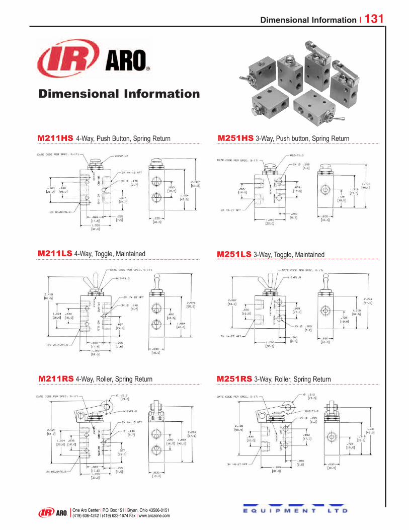
M211HS 4-Way, Push Button, Spring Return M251HS 3-Way, Push button, Spring Return
M251LS 3-Way, Toggle, Maintained
M251RS 3-Way, Roller, Spring Return
M211LS 4-Way, Toggle, Maintained
M211RS 4-Way, Roller, Spring Return
Dimensional Information
One Aro Center | P.O. Box 151 | Bryan, Ohio 43506-0151(419) 636-4242 | (419) 633-1674 Fax | www.arozone.com
Dimensional Information | 131
Colin
Logo1

Notes

Pneumatic Valves
• Repairable NFPA-Interchangeable Cylinders (1-1/2” to 8” bore sizes) and Round Line Cylinders (1-1/2” to 4” bore sizes).
• Disposable Cylinder - 1/2” to 1-1/2” bore sizes.• A wide selection of attachable
mounts.
• ISO valves - 1/4” and 3/8” ports.• In-line Manifold valves and spool valves (Body, sub-base, and
stacking styles 10/32” to 1” ports).Genesis EasyWire Valve Communication Systems (Parallel, Serial, and DeviceNet).
• Miniature, Flow Control Valves, and Circuitry Valves - mechanical, manual, solenoid, and pilot operated.
• Air line filters, regulators, and lubricator 1/8” to 1-1/2” ports.• Module/Air 1000 1/8” - 1/4”.• Module/Air 2000 1/4”, 3/8” -1/2”.• Heavy Duty 1/2”, 3/4” - 1”.• Super Duty 3/4”, 1”, 1 1/4”, 1 1/2”, 2”.• Safety blow guns.• Tool suspension balancers
and coil hose.
• Self-contained for sequentially controlled machines and custom-designed Circuit Board Construction from stock components.
• Wide selection of panel-mounted controls, indicators, counters and timers, sensing devices and enclosures.
Air Line Accessories
MEETINGYOURPNEUMATICCIRCUITNEEDS WITHCOMPLETEPRODUCTAND SYSTEMRELIABILITY
All ARO® Fluid Powerproducts are designed,built and tested to meetthe most demandingcustomer needs. AROproducts deliver clearlysuperior performancein the most challengingin-plant and O.E.M.applications. Aro has awide selection of FluidPower products whichallow design criteriaand specific applicationrequirements to be metwith maximumflexibility.
Pneumatic Cylinders
Pneumatic Logic Controls
Colin
Logo1

0020-M 0503 © 2002 IR/AROCPN 99921066
NORTH AMERICAUnited StatesOne Aro Center, P.O. Box 151Bryan, Ohio 43506-0151PHONE: (419) 636-4242FAX: (419) 633-1674
CanadaProduction Equipment GroupIngersoll-Rand Canada Inc.51 Worcester RoadRexdale, Ontario M9W 4K2PHONE: 1 (416) 213-4500FAX: 1 (416) 213-4510
LATIN AMERICALatin AmericaHeadquartersIngersoll-Rand PEG Aro Division730 N.W. 107 Ave.,Suite 300Miami, FL 33172-3107PH: (305) 222-0812/559-0500FAX:(305) 222-0864/559-7505
BrazilIngersoll-Rand do Brasil Ltda.Av. Dr. Cardoso de Melo 1855 Cep. 04548-005 São Paulo S.P. 5511 822 7400PH: (55-11) 3049 8900FAX: (55-11) 3842 3924
ChileIngersoll-Rand Chile, Ltda.Nueva Tajamar 555Oficina 1502Santiago, ChilePH: 56-2 339-7939FAX: 56-2 339-7940
MexicoIngersoll-Rand, S.A. de C.V.Blvd. Centro Industrial No.11Industrial Puente de Vigas 54070 Tlanepantla, Edo. Mex.PH: (52) 850 36 600FAX: (52) 5565 3072
EUROPEEuropean HeadquartersEurope, Africa & Middle EastIngersoll-RandZone du Chêne SorcierB.P. 62Les Clayes sous BoisCedex - FrancePH: (33) 01 30 07 69 50FAX: (33) 01 30 07 69 69
ASIAJapanIngersoll-Rand Japan, Ltd.LS Bldg., 1-1-17 Kami-OhsakiShinagawa-kuTokyo 141-0021JapanPH: (81) 45-476-7801FAX: (81) 45-476-7806
SingaporeIngersoll-Rand S.E.A. Pte Ltd.42, Benoi RoadSingapore 2262PH: (65) 8611555FAX: (65) 8610317
AustraliaIngersoll-Rand (Australia) Ltd.Landmark Corporate CentreLevel 2, 454-472 Nepean HighwayFrankston, Victoria 3199, AustraliaPH: (61) 3 8781-1600FAX: (61) 3 9554-1611
China / Hong KongIngersoll-Rand Asia Pacific23/F, 625 King’s RoadNorth PointHong KongPH: (852) 2527-0183FAX: (852) 2529-5976
KoreaIngersoll-Rand Korea#395-43, Seogyo-dongMapo-gu, Seoul 121-210KoreaPH: (82) 2-703-8461 / 3FAX: (82) 2-3272-5894
TaiwanIngersoll-Rand Taiwan12F-2, No. 79Shin-Tai Wu RoadSec. 1, Hsi-Chih TownTaipei Hsien, Taiwan, R.O.C.PH: 886-2-698-4858 Ext. 18FAX: 886-2-698-9897
www.arozone.com
Colin
Logo w/contact
Related Documents