Model FWD Pneumatic Centering Vise New 【Built-in Check Valve】

Welcome message from author
This document is posted to help you gain knowledge. Please leave a comment to let me know what you think about it! Share it to your friends and learn new things together.
Transcript

Model FWD
CAT.NO. SBR-FWD001-01-GBPrinted in Japan
2020/08 First PDF
▶ http://www.kosmek.com/
1-5, 2-chome, Murotani, Nishi-ku, Kobe-city, Hyogo, Japan 651-2241TEL.+81-78-991-5162 FAX.+81-78-991-8787
■ For Further Information on Unlisted Specifications and Sizes, Please call us.■ Specifications in this Leaflet are Subject to Change without Notice.
HEAD OFFICE
KOSMEK LTD.
KOSMEK (USA) LTD.650 Springer Drive, Lombard, IL 60148 USATEL. +1-630-620-7650 FAX. +1-630-620-9015
FAX. +43-463-287587-20
United States of AmericaSUBSIDIARY
KOSMEK USA Mexico Office
TEL. +52-1-55-3044-9983
MEXICOREPRESENTATIVE OFFICE
KOSMEK Thailand Representation Office67 Soi 58, RAMA 9 Rd., Phatthanakan, Suanluang, Bangkok 10250, Thailand
THAILANDREPRESENTATIVE OFFICE
KOSMEK EUROPE GmbH Schleppeplatz 2 9020 Klagenfurt am Wörthersee AustriaTEL. +43-463-287587
EUROPESUBSIDIARY
TEL.+91-9880561695
KOSMEK LTD. - INDIAF 203, Level-2, First Floor, Prestige Center Point, Cunningham Road, Bangalore -560052 India
INDIABRANCH OFFICE
FAX. +66-2-300-5133TEL. +66-2-300-5132
Av. Santa Fe 103, Int. 59, col. Santa Fe Juriquilla, Queretaro, QRO, 76230, Mexico
CHINASUBSIDIARY
TEL. +86-21-54253000
KOSMEK (CHINA) LTD.Room601, RIVERSIDE PYRAMID No.55, Lane21, Pusan Rd, Pudong Shanghai 200125, China
Pneumatic Centering ViseNew
【Built-in Check Valve】
21
Model No. /Specifications
ActionDescription
PerformanceCurve
ExternalDimensions
Lever DesignDimensions CautionsApplication
Examples
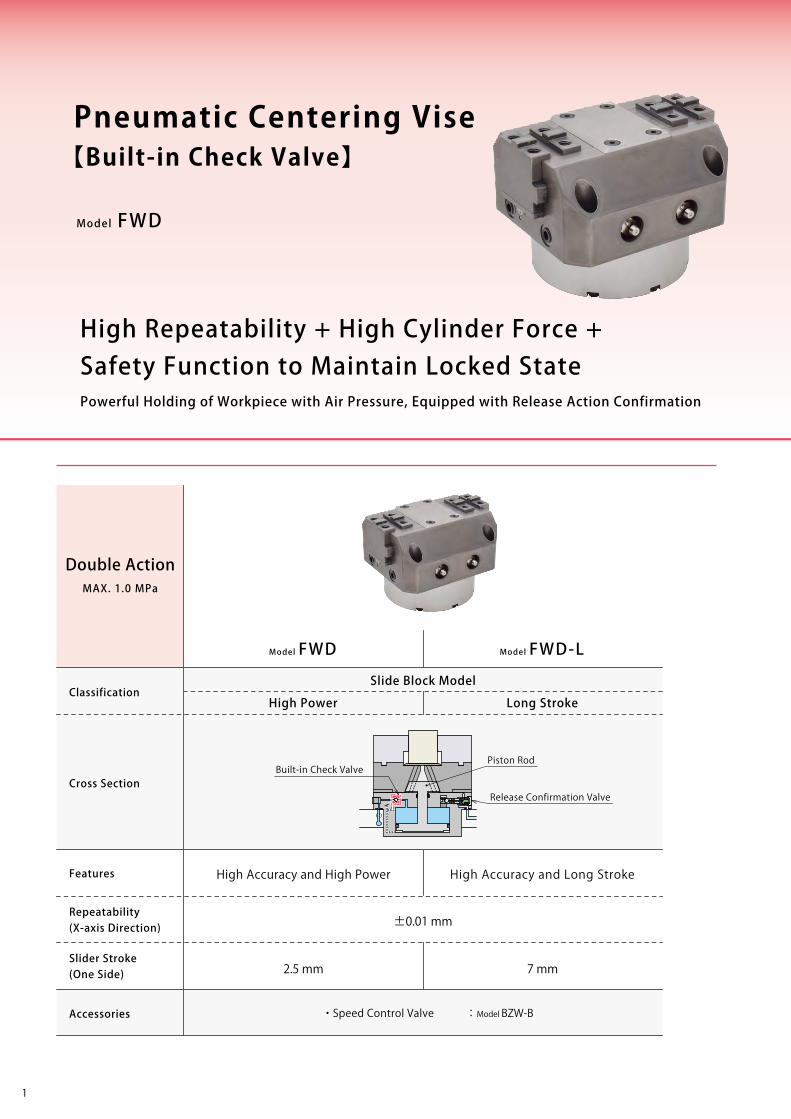
±0.01 mm
2.5 mm 7 mm
Model FWD Model FWD-L
Model FWD
Pneumatic Centering Vise
High Repeatability + High Cylinder Force +Safety Function to Maintain Locked StatePowerful Holding of Workpiece with Air Pressure, Equipped with Release Action Confirmation
Classification
Cross Section
Repeatability(X-axis Direction)
Features
Slider Stroke(One Side)
Accessories
Double ActionMAX. 1.0 MPa
Slide Block Model
High Power Long Stroke
High Accuracy and High Power High Accuracy and Long Stroke
・Speed Control Valve : Model BZW-B
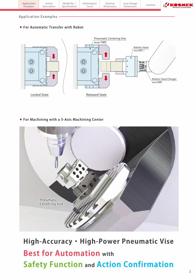
For Automatic Transfer with Robot
Pneumatic Centering ViseModel FWD
Robotic Hand ChangerModel SWR
Robotic HandModel WP□
Application Examples
Locked State Released State
For Machining with a 5-Axis Machining Center
PneumaticCentering VisePneumaticCentering Vise
High-Accuracy ・ High-Power Pneumatic Vise
Safety Function and Action ConfirmationBest for Automation with
【Built-in Check Valve】
Piston Rod
Release Confirmation Valve
Built-in Check Valve
21
Model No. /Specifications
ActionDescription
PerformanceCurve
ExternalDimensions
Lever DesignDimensions CautionsApplication
Examples
±0.01 mm
2.5 mm 7 mm
Model FWD Model FWD-L
Model FWD
Pneumatic Centering Vise
High Repeatability + High Cylinder Force +Safety Function to Maintain Locked StatePowerful Holding of Workpiece with Air Pressure, Equipped with Release Action Confirmation
Classification
Cross Section
Repeatability(X-axis Direction)
Features
Slider Stroke(One Side)
Accessories
Double ActionMAX. 1.0 MPa
Slide Block Model
High Power Long Stroke
High Accuracy and High Power High Accuracy and Long Stroke
・Speed Control Valve : Model BZW-B
For Automatic Transfer with Robot
Pneumatic Centering ViseModel FWD
Robotic Hand ChangerModel SWR
Robotic HandModel WP□
Application Examples
Locked State Released State
For Machining with a 5-Axis Machining Center
PneumaticCentering VisePneumaticCentering Vise
High-Accuracy ・ High-Power Pneumatic Vise
Safety Function and Action ConfirmationBest for Automation with
【Built-in Check Valve】
Piston Rod
Release Confirmation Valve
Built-in Check Valve
43
Model No. /Specifications
ActionDescription
PerformanceCurve
ExternalDimensions
Lever DesignDimensions CautionsApplication
Examplesmodel FWDPneumatic Centering Vise
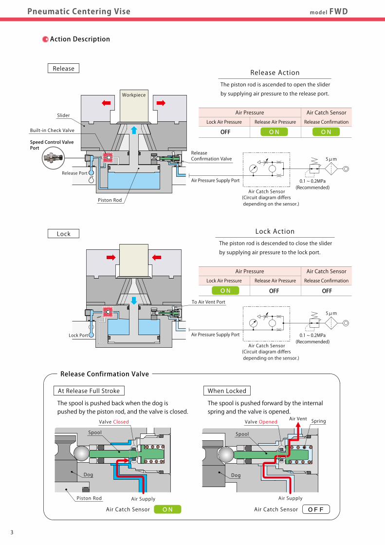
The spool is pushed forward by the internal spring and the valve is opened.
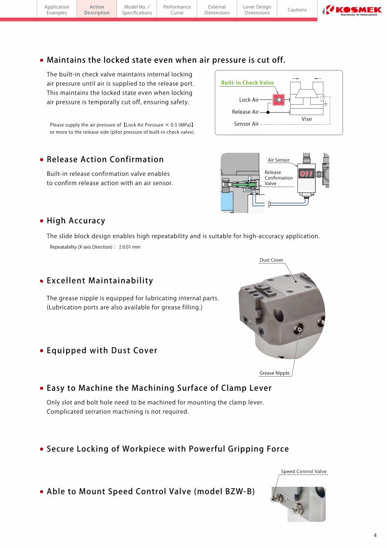
Excel lent Maintainabil ity
The grease nipple is equipped for lubricating internal parts.(Lubrication ports are also available for grease filling.)
Equipped with Dust Cover
Able to Mount Speed Control Valve (model BZW-B)
Dust Cover
Grease Nipple
High Accuracy
The slide block design enables high repeatability and is suitable for high-accuracy application.
Easy to Machine the Machining Surface of Clamp Lever
Secure Locking of Workpiece with Powerful Gripping Force
Only slot and bolt hole need to be machined for mounting the clamp lever.Complicated serration machining is not required.
Maintains the locked state even when air pressure is cut off.
The built-in check valve maintains internal locking air pressure until air is supplied to the release port. This maintains the locked state even when locking air pressure is temporally cut off, ensuring safety.
Release Action Confirmation
Built-in release confirmation valve enables to confirm release action with an air sensor.
Repeatability (X-axis Direction): ±0.01 mm
Please supply the air pressure of【Lock Air Pressure × 0.5 (MPa)】 or more to the release side (pilot pressure of built-in check valve).
The spool is pushed back when the dog is pushed by the piston rod, and the valve is closed.
Spring
Air Supply
Air Vent
Air Catch SensorON OFF
Lock Air
Sensor AirVise
Release Air
OFFReleaseConfirmationValve
Air Sensor
Speed Control Valve
Action Description
Lock
Release Release Action
The piston rod is ascended to open the slider
by supplying air pressure to the release port.
Speed Control ValvePort
Lock Air Pressure Release Air Pressure Release Confirmation
Air Pressure Air Catch Sensor
ON ONOFF
Air Pressure Supply Port
Air Catch Sensor(Circuit diagram differs depending on the sensor.)
0.1 ~ 0.2MPa(Recommended)
5μm
Release Port
Workpiece
Piston Rod
Slider
ReleaseConfirmation Valve
Lock Port
Lock Air Pressure Release Air Pressure Release Confirmation
Air Pressure Air Catch Sensor
ON OFF OFF
0.1 ~ 0.2MPa(Recommended)
5μm
To Air Vent Port
Lock Action
The piston rod is descended to close the slider
by supplying air pressure to the lock port.
Air Catch Sensor(Circuit diagram differs depending on the sensor.)
Air Pressure Supply Port
At Release Full Stroke When Locked
Release Confirmation Valve
Spool
Valve Closed
Dog
Piston Rod Air Supply
Air Catch Sensor
Dog
Spool
Valve Opened
Built-in Check Valve
Built-in Check Valve
43
Model No. /Specifications
ActionDescription
PerformanceCurve
ExternalDimensions
Lever DesignDimensions CautionsApplication
Examplesmodel FWDPneumatic Centering Vise
The spool is pushed forward by the internal spring and the valve is opened.
Excel lent Maintainabil ity
The grease nipple is equipped for lubricating internal parts.(Lubrication ports are also available for grease filling.)
Equipped with Dust Cover
Able to Mount Speed Control Valve (model BZW-B)
Dust Cover
Grease Nipple
High Accuracy
The slide block design enables high repeatability and is suitable for high-accuracy application.
Easy to Machine the Machining Surface of Clamp Lever
Secure Locking of Workpiece with Powerful Gripping Force
Only slot and bolt hole need to be machined for mounting the clamp lever.Complicated serration machining is not required.
Maintains the locked state even when air pressure is cut off.
The built-in check valve maintains internal locking air pressure until air is supplied to the release port. This maintains the locked state even when locking air pressure is temporally cut off, ensuring safety.
Release Action Confirmation
Built-in release confirmation valve enables to confirm release action with an air sensor.
Repeatability (X-axis Direction): ±0.01 mm
Please supply the air pressure of【Lock Air Pressure × 0.5 (MPa)】 or more to the release side (pilot pressure of built-in check valve).
The spool is pushed back when the dog is pushed by the piston rod, and the valve is closed.
Spring
Air Supply
Air Vent
Air Catch SensorON OFF
Lock Air
Sensor AirVise
Release Air
OFFReleaseConfirmationValve
Air Sensor
Speed Control Valve
Action Description
Lock
Release Release Action
The piston rod is ascended to open the slider
by supplying air pressure to the release port.
Speed Control ValvePort
Lock Air Pressure Release Air Pressure Release Confirmation
Air Pressure Air Catch Sensor
ON ONOFF
Air Pressure Supply Port
Air Catch Sensor(Circuit diagram differs depending on the sensor.)
0.1 ~ 0.2MPa(Recommended)
5μm
Release Port
Workpiece
Piston Rod
Slider
ReleaseConfirmation Valve
Lock Port
Lock Air Pressure Release Air Pressure Release Confirmation
Air Pressure Air Catch Sensor
ON OFF OFF
0.1 ~ 0.2MPa(Recommended)
5μm
To Air Vent Port
Lock Action
The piston rod is descended to close the slider
by supplying air pressure to the lock port.
Air Catch Sensor(Circuit diagram differs depending on the sensor.)
Air Pressure Supply Port
At Release Full Stroke When Locked
Release Confirmation Valve
Spool
Valve Closed
Dog
Piston Rod Air Supply
Air Catch Sensor
Dog
Spool
Valve Opened
Built-in Check Valve
Built-in Check Valve

65
Model No. /Specifications
ActionDescription
PerformanceCurve
ExternalDimensions
Lever DesignDimensions CautionsApplication
Examplesmodel FWDPneumatic Centering Vise
Action Description (Air Sensing Chart Explanation)
Notes : 1. The sensing chart shows the relationship between the slider stroke and the air catch sensor pressure. 2. The specifications may vary depending on the air circuit. The hose length should be as short as possible. (Suggest less than 5m) ※1. There is certain tolerance with regard to the position where the pressure for closing the valve is reached depending on the cylinder structure. (Refer to the sensing chart.) ※2. The position where the air catch sensor turns ON signal output varies depending on the sensor setting. ※3. The sensor pressure when the valve is opened differs depending on a sensor. In case of a sensor with large air consumption, the sensor pressure when the valve is opened increases and differential pressure decreases.
When Connected to 1 Pneumatic Centering ViseAction confirmation can be conducted by detecting
differential pressure with the air catch sensor.
● The air catch sensor is necessary for action confirmation.
● Please refer to manufacturer's catalog etc. for the detail of the air sensor.
● The supply air pressure to the air catch sensor should be 0.1 ~ 0.2MPa.
● Continuously supply air pressure when in use.
● Refer to the drawing below for the air circuit structure.
● Please keep clear condition at the sensor air vent port,
and prevent coolant and chips from entering the port.
The air catch sensor can malfunction if the air vent
port is blocked.
● Continuously supply air pressure to the air port for sensing
when in use.
● Set a check valve with low cracking pressure to the
detection port of the air sensor. (Recommended Check
Valve: SMC-made AKH series, cracking pressure: 0.005MPa)
Check Valve
About Air Catch Sensor
Notes for Design・Installation・Use
Sensing can be done by air catch sensor with the small air flow (recommended model in the list below).
Recommended Air Catch Sensor
Recommended Operating Air Pressure : 0.1 ~ 0.2 MPa
Air Sensing Chart
Release Confirmation
※2
※1
※3
When releasing after locked state
Keeping clear condition at the sensor air vent port.
Coolant and chips enteringfrom the sensor air vent port.
Manufacturer
Name
Model
SMC
Air Catch Sensor
ISA3-G
CKD
Gap Switch
GPS3-E
0.1 ~ 0.2MPa(Recommended)
Air Catch Sensor 5μm
Slider Stroke (One Side)
0.5 (mm)
Slider Stroke (One Side)
Air Catch Sensor Pressure (MPa)
0 .2
0
Air Catch Sensor Set Pressure (ON)
(Supply Air Pressure)
Release EndLock End
Pressure when Valve Opened
0 - 0.5
Differential Pressure
for Detection
Pressure when Valve Closed
87
Model No. /Specifications
ActionDescription
PerformanceCurve
ExternalDimensions
Lever DesignDimensions CautionsApplication
Examplesmodel FWDPneumatic Centering Vise
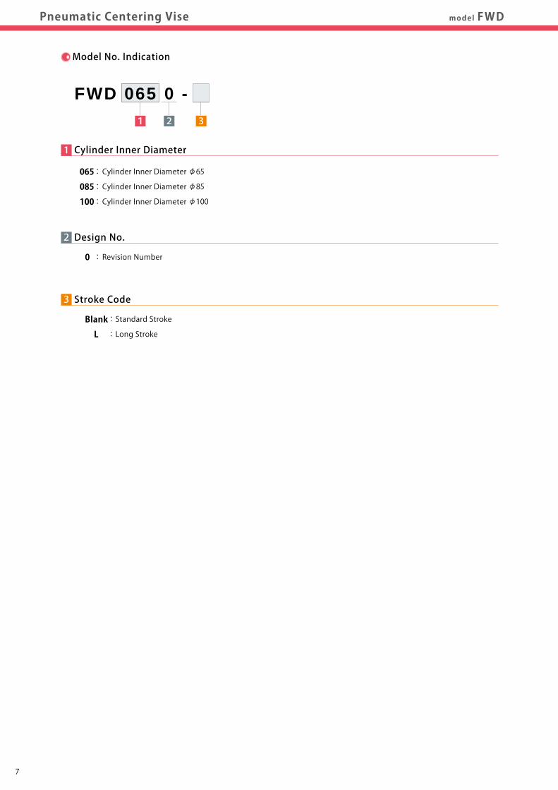
Model No. Indication
2
0 : Revision Number
Design No.
3
Blank : Standard Stroke
L : Long Stroke
Stroke Code
1 Cylinder Inner Diameter
065 : Cylinder Inner Diameter φ65
085 : Cylinder Inner Diameter φ85
100 : Cylinder Inner Diameter φ100
1 2 3
FWD 065 0 -
Notes : 1. Excessively fast operating speed of the centering vise may lead to wear-out or damage internal components. Adjust the operating speed so that the slider fully strokes within the following time period. Standard Stroke:0.5 ~ 1.0 sec Long Stroke:1.0 ~ 1.5 sec 2. Secure the extra stroke of 1mm or more. ※1. Clamping force cannot be calculated from the cylinder inner diameter and rod diameter. Please refer to the clamping force curve. ※2. Supply the air pressure of 【Lock Air Pressure × 0.5 (MPa)】 or more to the release side (pilot pressure of built-in check valve). ※3. Repeatability under the same condition.
Specifications Model No.
Slider Stroke
(One Side)
Max. Clamping Height
(At 1MPa)
Cylinder Diameter
Rod Diameter
Cylinder Area
Cylinder Capacity
Max. Operating Pressure
Min. Operating Pressure
Withstanding Pressure
Recommended Air Catch Sensor Pressure
Recommended Air Catch Sensor
Repeatability (X-axis Direction)
Operating Temperature
Usable Fluid
Weight
Blank
L
Blank
L
Lock
Release
Lock
Release
FWD0650-□
35
75
65
12
32.1
33.2
64.1
66.4
3.5
FWD0850-□
2.5
7
45
100
85
16
54.7
56.7
109.5
113.5
1.0
0.2
1.5
0.1 ~ 0.2
ISA3-G (made by SMC) / GPS3-E (made by CKD)
±0.01
0 ~ 70
Dry Air
5.4
FWD1000-□
55
125
100
20
75.4
78.5
150.8
157.1
7.4
mm
mm
MPa
MPa
MPa
MPa
mm
℃
kg
cm3
cm2
mm
mm
※3
※2
※1
※1
3
3
3
3
Clamping Height
XSlider Stroke (One Side)

87
Model No. /Specifications
ActionDescription
PerformanceCurve
ExternalDimensions
Lever DesignDimensions CautionsApplication
Examplesmodel FWDPneumatic Centering Vise
Model No. Indication
2
0 : Revision Number
Design No.
3
Blank : Standard Stroke
L : Long Stroke
Stroke Code
1 Cylinder Inner Diameter
065 : Cylinder Inner Diameter φ65
085 : Cylinder Inner Diameter φ85
100 : Cylinder Inner Diameter φ100
1 2 3
FWD 065 0 -
Notes : 1. Excessively fast operating speed of the centering vise may lead to wear-out or damage internal components. Adjust the operating speed so that the slider fully strokes within the following time period. Standard Stroke:0.5 ~ 1.0 sec Long Stroke:1.0 ~ 1.5 sec 2. Secure the extra stroke of 1mm or more. ※1. Clamping force cannot be calculated from the cylinder inner diameter and rod diameter. Please refer to the clamping force curve. ※2. Supply the air pressure of 【Lock Air Pressure × 0.5 (MPa)】 or more to the release side (pilot pressure of built-in check valve). ※3. Repeatability under the same condition.
Specifications Model No.
Slider Stroke
(One Side)
Max. Clamping Height
(At 1MPa)
Cylinder Diameter
Rod Diameter
Cylinder Area
Cylinder Capacity
Max. Operating Pressure
Min. Operating Pressure
Withstanding Pressure
Recommended Air Catch Sensor Pressure
Recommended Air Catch Sensor
Repeatability (X-axis Direction)
Operating Temperature
Usable Fluid
Weight
Blank
L
Blank
L
Lock
Release
Lock
Release
FWD0650-□
35
75
65
12
32.1
33.2
64.1
66.4
3.5
FWD0850-□
2.5
7
45
100
85
16
54.7
56.7
109.5
113.5
1.0
0.2
1.5
0.1 ~ 0.2
ISA3-G (made by SMC) / GPS3-E (made by CKD)
±0.01
0 ~ 70
Dry Air
5.4
FWD1000-□
55
125
100
20
75.4
78.5
150.8
157.1
7.4
mm
mm
MPa
MPa
MPa
MPa
mm
℃
kg
cm3
cm2
mm
mm
※3
※2
※1
※1
3
3
3
3
XSlider Stroke (One Side)
Clamping Height
109
Model No. /Specifications
ActionDescription
PerformanceCurve
ExternalDimensions
Lever DesignDimensions CautionsApplication
Examplesmodel FWDPneumatic Centering Vise
Air Pressure (MPa)
1.0 0.9 0.8 0.7 0.6 0.5 0.4 0.3 0.2
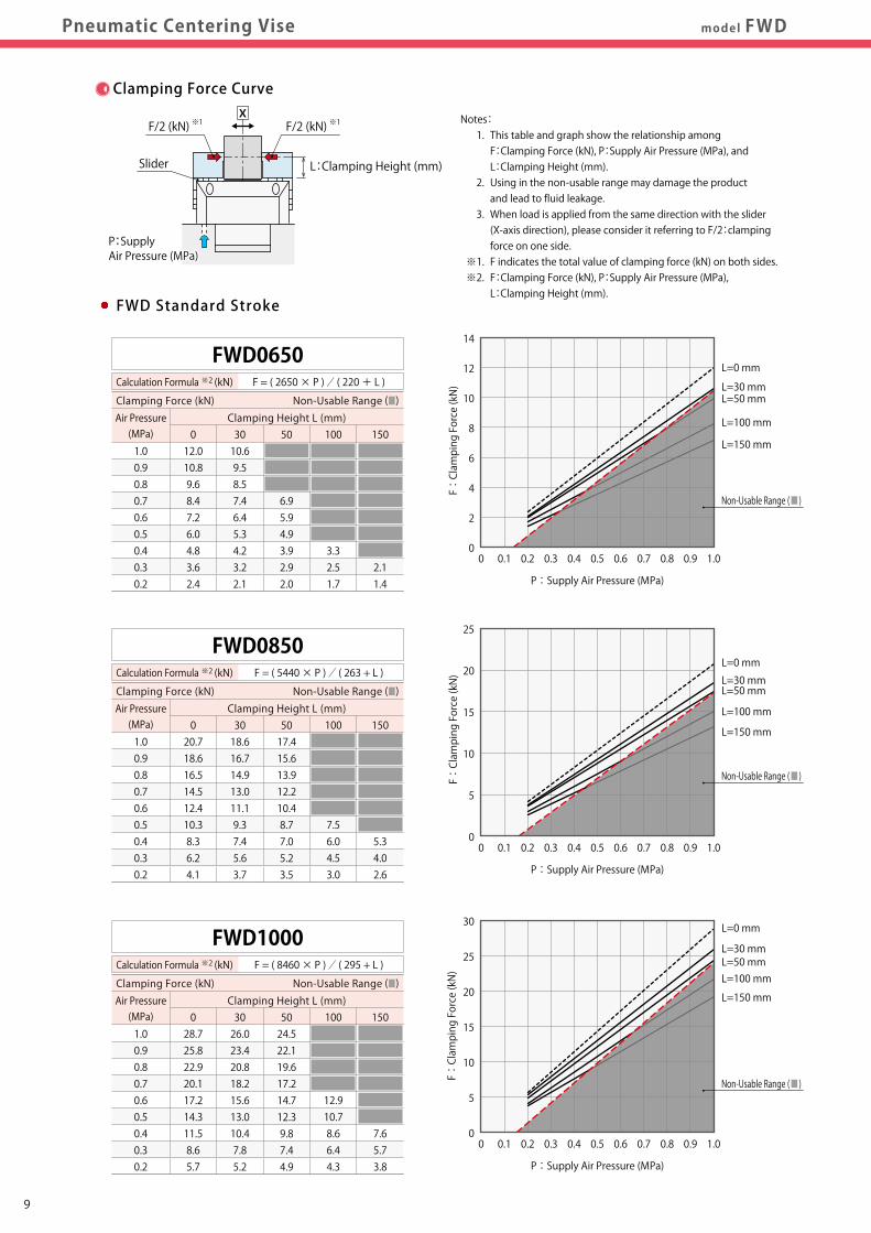
FWD0650Calculation Formula ※2 (kN) F = ( 2650 × P ) / ( 220 + L )
Clamping Height L (mm)012.010.89.68.47.26.04.83.62.4
3010.69.58.57.46.45.34.23.22.1
50
6.95.94.93.92.92.0
Clamping Force (kN) Non-Usable Range (■)
Notes: 1. This table and graph show the relationship among F:Clamping Force (kN), P:Supply Air Pressure (MPa), and L:Clamping Height (mm). 2. Using in the non-usable range may damage the product and lead to fluid leakage. 3. When load is applied from the same direction with the slider (X-axis direction), please consider it referring to F/2:clamping force on one side. ※1. F indicates the total value of clamping force (kN) on both sides. ※2. F:Clamping Force (kN), P:Supply Air Pressure (MPa), L:Clamping Height (mm).
100
3.32.51.7
150
2.11.4
0
2
4
6
8
10
12
14
0 0.1 0.2 0.3 0.4 0.5 0.6 0.7 0.8 0.9 1.0
L=0 mm
L=50 mmL=30 mm
L=100 mm
L=150 mm
P:Supply Air Pressure (MPa)
F:Clamping Force (kN)
FWD Standard Stroke
L:Clamping Height (mm)
P:SupplyAir Pressure (MPa)P:SupplyAir Pressure (MPa)
※1F/2 (kN)
Slider
※1F/2 (kN)X
Air Pressure (MPa)
1.0 0.9 0.8 0.7 0.6 0.5 0.4 0.3 0.2
FWD0850Calculation Formula ※2 (kN) F = ( 5440 × P ) / ( 263 + L )
Clamping Height L (mm)020.718.616.514.512.410.38.36.24.1
3018.616.714.913.011.19.37.45.63.7
5017.415.613.912.210.48.77.05.23.5
100
7.56.04.53.0
150
5.34.02.6
0
5
10
15
20
25
0 0.1 0.2 0.3 0.4 0.5 0.6 0.7 0.8 0.9 1.0
L=0 mm
L=50 mmL=30 mm
L=100 mm
L=150 mm
P:Supply Air Pressure (MPa)
F:Clamping Force (kN)
Air Pressure (MPa)
1.0 0.9 0.8 0.7 0.6 0.5 0.4 0.3 0.2
FWD1000Calculation Formula ※2 (kN) F = ( 8460 × P ) / ( 295 + L )
Clamping Height L (mm)028.725.822.920.117.214.311.58.65.7
3026.023.420.818.215.613.010.47.85.2
5024.522.119.617.214.712.39.87.44.9
100
12.910.78.66.44.3
150
7.65.73.8
Air Pressure (MPa)
1.0 0.9 0.8 0.7 0.6 0.5 0.4 0.3 0.2
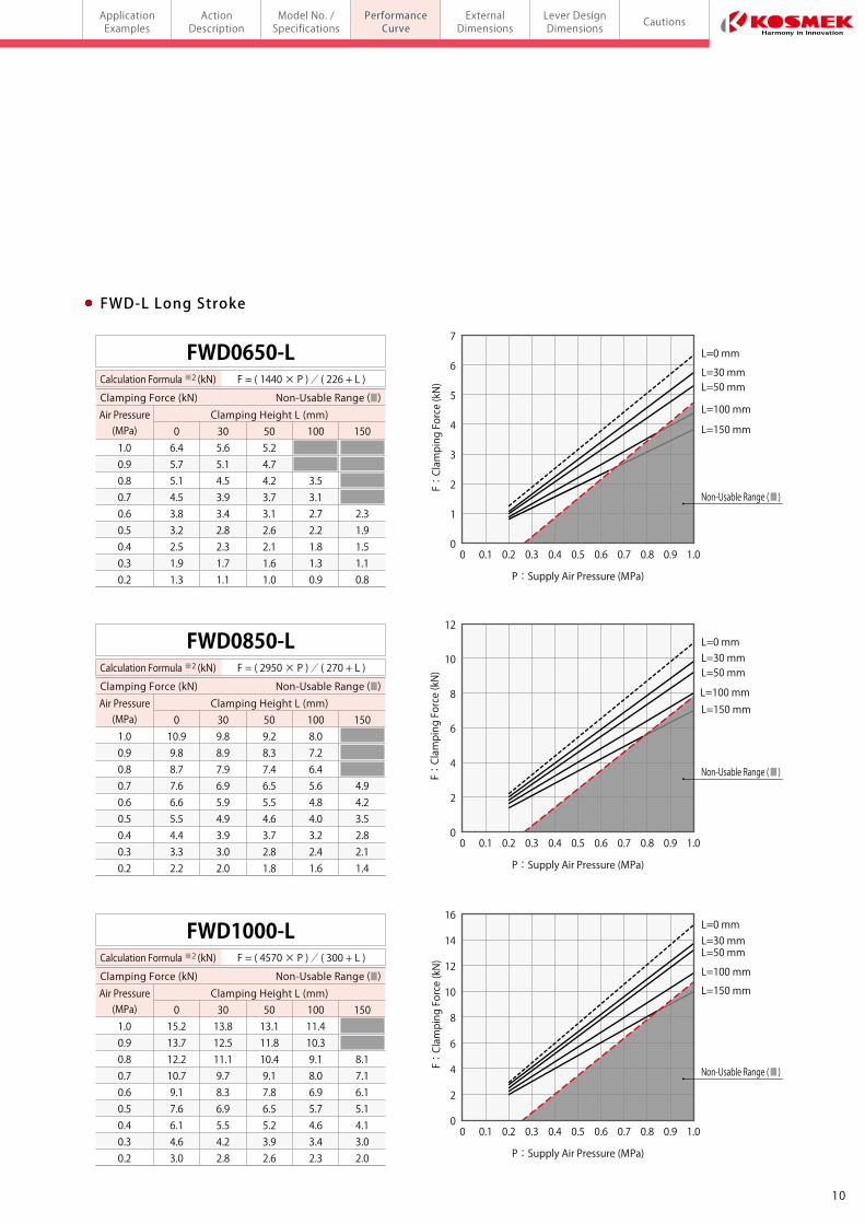
FWD0650-LCalculation Formula ※2 (kN) F = ( 1440 × P ) / ( 226 + L )
Clamping Height L (mm)06.45.75.14.53.83.22.51.91.3
305.65.14.53.93.42.82.31.71.1
505.24.74.23.73.12.62.11.61.0
100
3.53.12.72.21.81.30.9
150
2.31.91.51.10.8
0
1
2
3
4
5
6
7
0 0.1 0.2 0.3 0.4 0.5 0.6 0.7 0.8 0.9 1.0
L=0 mm
L=50 mmL=30 mm
L=100 mm
L=150 mm
P:Supply Air Pressure (MPa)
F:Clamping Force (kN)
FWD-L Long Stroke
Air Pressure (MPa)
1.0 0.9 0.8 0.7 0.6 0.5 0.4 0.3 0.2
FWD0850-LCalculation Formula ※2 (kN) F = ( 2950 × P ) / ( 270 + L )
Clamping Height L (mm)010.99.88.77.66.65.54.43.32.2
309.88.97.96.95.94.93.93.02.0
509.28.37.46.55.54.63.72.81.8
1008.07.26.45.64.84.03.22.41.6
150
4.94.23.52.82.11.4
0
2
4
6
8
10
12
0 0.1 0.2 0.3 0.4 0.5 0.6 0.7 0.8 0.9 1.0
L=0 mm
L=50 mmL=30 mm
L=100 mmL=150 mm
P:Supply Air Pressure (MPa)
F:Clamping Force (kN)
Air Pressure (MPa)
1.0 0.9 0.8 0.7 0.6 0.5 0.4 0.3 0.2
FWD1000-LCalculation Formula ※2 (kN) F = ( 4570 × P ) / ( 300 + L )
Clamping Height L (mm)015.213.712.210.79.17.66.14.63.0
3013.812.511.19.78.36.95.54.22.8
5013.111.810.49.17.86.55.23.92.6
10011.410.39.18.06.95.74.63.42.3
150
8.17.16.15.14.13.02.0
Clamping Force Curve
0
5
10
15
20
25
30
0 0.1 0.2 0.3 0.4 0.5 0.6 0.7 0.8 0.9 1.0
L=0 mm
L=50 mmL=30 mm
L=100 mm
L=150 mm
P:Supply Air Pressure (MPa)
F:Clamping Force (kN)
0
2
4
6
8
10
12
14
16
0 0.1 0.2 0.3 0.4 0.5 0.6 0.7 0.8 0.9 1.0
L=0 mm
L=50 mmL=30 mm
L=100 mm
L=150 mm
P:Supply Air Pressure (MPa)
F:Clamping Force (kN)
Non-Usable Range (■)
Non-Usable Range (■)
Non-Usable Range (■)
Non-Usable Range (■)
Non-Usable Range (■)
Non-Usable Range (■)
Clamping Force (kN) Non-Usable Range (■)
Clamping Force (kN) Non-Usable Range (■)
Clamping Force (kN) Non-Usable Range (■)
Clamping Force (kN) Non-Usable Range (■)
Clamping Force (kN) Non-Usable Range (■)
109
Model No. /Specifications
ActionDescription
PerformanceCurve
ExternalDimensions
Lever DesignDimensions CautionsApplication
Examplesmodel FWDPneumatic Centering Vise
Air Pressure (MPa)
1.0 0.9 0.8 0.7 0.6 0.5 0.4 0.3 0.2
FWD0650Calculation Formula ※2 (kN) F = ( 2650 × P ) / ( 220 + L )
Clamping Height L (mm)012.010.89.68.47.26.04.83.62.4
3010.69.58.57.46.45.34.23.22.1
50
6.95.94.93.92.92.0
Clamping Force (kN) Non-Usable Range (■)
Notes: 1. This table and graph show the relationship among F:Clamping Force (kN), P:Supply Air Pressure (MPa), and L:Clamping Height (mm). 2. Using in the non-usable range may damage the product and lead to fluid leakage. 3. When load is applied from the same direction with the slider (X-axis direction), please consider it referring to F/2:clamping force on one side. ※1. F indicates the total value of clamping force (kN) on both sides. ※2. F:Clamping Force (kN), P:Supply Air Pressure (MPa), L:Clamping Height (mm).
100
3.32.51.7
150
2.11.4
0
2
4
6
8
10
12
14
0 0.1 0.2 0.3 0.4 0.5 0.6 0.7 0.8 0.9 1.0
L=0 mm
L=50 mmL=30 mm
L=100 mm
L=150 mm
P:Supply Air Pressure (MPa)
F:Clamping Force (kN)
FWD Standard Stroke
L:Clamping Height (mm)
P:SupplyAir Pressure (MPa)P:SupplyAir Pressure (MPa)
※1F/2 (kN)
Slider
※1F/2 (kN)X
Air Pressure (MPa)
1.0 0.9 0.8 0.7 0.6 0.5 0.4 0.3 0.2
FWD0850Calculation Formula ※2 (kN) F = ( 5440 × P ) / ( 263 + L )
Clamping Height L (mm)020.718.616.514.512.410.38.36.24.1
3018.616.714.913.011.19.37.45.63.7
5017.415.613.912.210.48.77.05.23.5
100
7.56.04.53.0
150
5.34.02.6
0
5
10
15
20
25
0 0.1 0.2 0.3 0.4 0.5 0.6 0.7 0.8 0.9 1.0
L=0 mm
L=50 mmL=30 mm
L=100 mm
L=150 mm
P:Supply Air Pressure (MPa)
F:Clamping Force (kN)
Air Pressure (MPa)
1.0 0.9 0.8 0.7 0.6 0.5 0.4 0.3 0.2
FWD1000Calculation Formula ※2 (kN) F = ( 8460 × P ) / ( 295 + L )
Clamping Height L (mm)028.725.822.920.117.214.311.58.65.7
3026.023.420.818.215.613.010.47.85.2
5024.522.119.617.214.712.39.87.44.9
100
12.910.78.66.44.3
150
7.65.73.8
Air Pressure (MPa)
1.0 0.9 0.8 0.7 0.6 0.5 0.4 0.3 0.2
FWD0650-LCalculation Formula ※2 (kN) F = ( 1440 × P ) / ( 226 + L )
Clamping Height L (mm)06.45.75.14.53.83.22.51.91.3
305.65.14.53.93.42.82.31.71.1
505.24.74.23.73.12.62.11.61.0
100
3.53.12.72.21.81.30.9
150
2.31.91.51.10.8
0
1
2
3
4
5
6
7
0 0.1 0.2 0.3 0.4 0.5 0.6 0.7 0.8 0.9 1.0
L=0 mm
L=50 mmL=30 mm
L=100 mm
L=150 mm
P:Supply Air Pressure (MPa)
F:Clamping Force (kN)
FWD-L Long Stroke
Air Pressure (MPa)
1.0 0.9 0.8 0.7 0.6 0.5 0.4 0.3 0.2
FWD0850-LCalculation Formula ※2 (kN) F = ( 2950 × P ) / ( 270 + L )
Clamping Height L (mm)010.99.88.77.66.65.54.43.32.2
309.88.97.96.95.94.93.93.02.0
509.28.37.46.55.54.63.72.81.8
1008.07.26.45.64.84.03.22.41.6
150
4.94.23.52.82.11.4
0
2
4
6
8
10
12
0 0.1 0.2 0.3 0.4 0.5 0.6 0.7 0.8 0.9 1.0
L=0 mm
L=50 mmL=30 mm
L=100 mmL=150 mm
P:Supply Air Pressure (MPa)
F:Clamping Force (kN)
Air Pressure (MPa)
1.0 0.9 0.8 0.7 0.6 0.5 0.4 0.3 0.2
FWD1000-LCalculation Formula ※2 (kN) F = ( 4570 × P ) / ( 300 + L )
Clamping Height L (mm)015.213.712.210.79.17.66.14.63.0
3013.812.511.19.78.36.95.54.22.8
5013.111.810.49.17.86.55.23.92.6
10011.410.39.18.06.95.74.63.42.3
150
8.17.16.15.14.13.02.0
Clamping Force Curve
0
5
10
15
20
25
30
0 0.1 0.2 0.3 0.4 0.5 0.6 0.7 0.8 0.9 1.0
L=0 mm
L=50 mmL=30 mm
L=100 mm
L=150 mm
P:Supply Air Pressure (MPa)
F:Clamping Force (kN)
0
2
4
6
8
10
12
14
16
0 0.1 0.2 0.3 0.4 0.5 0.6 0.7 0.8 0.9 1.0
L=0 mm
L=50 mmL=30 mm
L=100 mm
L=150 mm
P:Supply Air Pressure (MPa)
F:Clamping Force (kN)
Non-Usable Range (■)
Non-Usable Range (■)
Non-Usable Range (■)
Non-Usable Range (■)
Non-Usable Range (■)
Non-Usable Range (■)
Clamping Force (kN) Non-Usable Range (■)
Clamping Force (kN) Non-Usable Range (■)
Clamping Force (kN) Non-Usable Range (■)
Clamping Force (kN) Non-Usable Range (■)
Clamping Force (kN) Non-Usable Range (■)

12
Model No. /Specifications
ActionDescription
PerformanceCurve
ExternalDimensions
Lever DesignDimensions CautionsApplication
Examplesmodel FWDPneumatic Centering Vise Standard Stroke
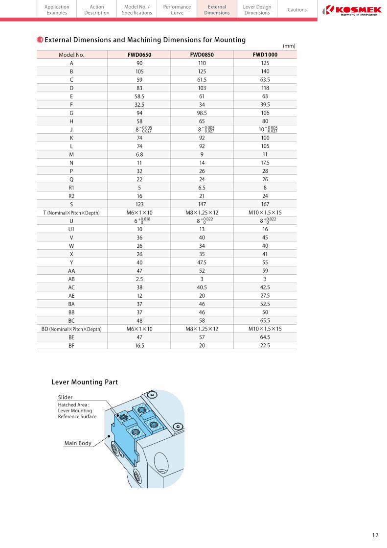
External Dimensions and Machining Dimensions for Mounting
+0.018 0
Model No.ABCDEFGHJKLMNPQR1R2S
T (Nominal×Pitch×Depth)UU1VWXYAAABACAEBABBBC
BD (Nominal×Pitch×Depth)BEBF
FWD065090105598358.532.594588 74746.8113222516123
M6×1×106 1036262640472.53812373748
M6×1×104716.5
FWD085011012561.5103613498.5658 929291426246.521147
M8×1.25×128 1340343547.552340.520464658
M8×1.25×125720
FWD100012514063.51186339.51068010 1001051117.52826824167
M10×1.5×158 164540415559342.527.552.55065.5
M10×1.5×1564.522.5
(mm)
+ 0.018 0
ー 0.005ー 0.027
ー 0.005ー 0.027
ー 0.005ー 0.027
+ 0.022 0
+ 0.022 0
Notes :
1. Roughness of mounting surface should be 6.3S or better.
2. Install a lever on the top of the slider when in use.
3. Please keep clear condition at the sensor air vent port, and
prevent coolant and chips from entering the port.
※1. Mounting bolts are not provided with the product. Please prepare
them according to the mounting height referring to dimension 'P'.
※2. Speed control valve is sold separately. Refer to P.19 for further information.
※3. Able to locate the body of centering vise by using φ6 hole. Please
consider X, Y dimension tolerance and φ6 hole tolerance according
to a locating pin. Locating pin is not included.
※4. When shipping, R-thread plugs are mounted to the grease nipple
installation port. Select one port each from ☆ and ★ ports and
install the grease nipples to the selected ports.
※5. The lubrication port enables to fill grease without using the grease
nipple. When using the lubrication port, remove the set screws.
※6. This machining is required only when using the lubrication port.
※5
※2
※2
※1
※3
※4
Slider Stroke
AV AAQ
2.5 B
L
φ16
2.5
K
(0 ~ 2)
W
R2 R1
U1 U
F
P G
E
HJg8
H8
10
φD-0.1-0.2
17AC
AB
AE AE
X±0.01 X±0.01
Y±0.01
Y±0.01
BE
22.5
22.5
Slider Stroke
C
φ15.5
Clamping
Height
4-φM
2-Grease Nipple (Included)A-PT1/8
8-T Thread
Lock PortO-ring:1BP5 (Included)
BE
BE BE
2-φ6H8 Depth 6
Sensor Air Vent PortO-ring:1BP5 (Included)
BC BC
Built-in Check Valve
BF22.5
φS Slider
Hatched Area : Lever Mounting Reference Surface
External Dimensions:FWD Standard Stroke※ The drawing shows the released state of FWD.
Machining Dimensions of Mounting Area
Lever (Preparedby Customer)
BZW0100-B(Sold Separately)
+0.30
φD
※6
※3
※3 ※3
※3
※3
X±0.01 X±0.01
Y±0.01
Y±0.01
BA BA
BBBB
22.5
22.5
BE BE
BE BE
BC BC
Lock Portφ3 or less
4-BD Thread
2-Lubrication Portφ3 or less
2-φ6 Depth 6
Sensor AirVent Portφ3 or less
BF22.5
Lever Mounting Part
11
(max.1)
(max.17)
(E)0.5
Spot FacingφN
Grease Nipple Installation Port:4-Rc1/8 Thread4-R1/8 R-Thread Plug (Included)
2-R1/8 R-Thread Plug (Included)
(Speed Control Valve Port)
2-Lubrication PortO-ring : SS5(NOK) (Included)M3×0.5×4 Set Screw (Included)
Release PortO-ring:1BP5 (Included)
Sensor Air Supply PortO-ring:1BP5 (Included)
Release Portφ3 or less
Sensor AirSupply Portφ3 or less
C0.4
Blind Hole Machining Through Hole Machining
F+2 or more
6.3S
SliderHatched Area : Lever MountingReference Surface
Main Body
12
Model No. /Specifications
ActionDescription
PerformanceCurve
ExternalDimensions
Lever DesignDimensions CautionsApplication
Examplesmodel FWDPneumatic Centering Vise Standard Stroke
External Dimensions and Machining Dimensions for Mounting
+0.018 0
Model No.ABCDEFGHJKLMNPQR1R2S
T (Nominal×Pitch×Depth)UU1VWXYAAABACAEBABBBC
BD (Nominal×Pitch×Depth)BEBF
FWD065090105598358.532.594588 74746.8113222516123
M6×1×106 1036262640472.53812373748
M6×1×104716.5
FWD085011012561.5103613498.5658 929291426246.521147
M8×1.25×128 1340343547.552340.520464658
M8×1.25×125720
FWD100012514063.51186339.51068010 1001051117.52826824167
M10×1.5×158 164540415559342.527.552.55065.5
M10×1.5×1564.522.5
(mm)
+ 0.018 0
ー 0.005ー 0.027
ー 0.005ー 0.027
ー 0.005ー 0.027
+ 0.022 0
+ 0.022 0
Notes :
1. Roughness of mounting surface should be 6.3S or better.
2. Install a lever on the top of the slider when in use.
3. Please keep clear condition at the sensor air vent port, and
prevent coolant and chips from entering the port.
※1. Mounting bolts are not provided with the product. Please prepare
them according to the mounting height referring to dimension 'P'.
※2. Speed control valve is sold separately. Refer to P.19 for further information.
※3. Able to locate the body of centering vise by using φ6 hole. Please
consider X, Y dimension tolerance and φ6 hole tolerance according
to a locating pin. Locating pin is not included.
※4. When shipping, R-thread plugs are mounted to the grease nipple
installation port. Select one port each from ☆ and ★ ports and
install the grease nipples to the selected ports.
※5. The lubrication port enables to fill grease without using the grease
nipple. When using the lubrication port, remove the set screws.
※6. This machining is required only when using the lubrication port.
※5
※2
※2
※1
※3
※4
Slider Stroke
AV AAQ
2.5 B
L
φ16
2.5
K
(0 ~ 2)
W
R2 R1
U1 U
F
P G
E
HJg8
H8
10
φD-0.1-0.2
17AC
AB
AE AE
X±0.01 X±0.01
Y±0.01
Y±0.01
BE
22.5
22.5
Slider Stroke
C
φ15.5
Clamping
Height
4-φM
2-Grease Nipple (Included)A-PT1/8
8-T Thread
Lock PortO-ring:1BP5 (Included)
BE
BE BE
2-φ6H8 Depth 6
Sensor Air Vent PortO-ring:1BP5 (Included)
BC BC
Built-in Check Valve
BF22.5
φS Slider
Hatched Area : Lever Mounting Reference Surface
External Dimensions:FWD Standard Stroke※ The drawing shows the released state of FWD.
Machining Dimensions of Mounting Area
Lever (Preparedby Customer)
BZW0100-B(Sold Separately)
+0.30
φD
※6
※3
※3 ※3
※3
※3
X±0.01 X±0.01
Y±0.01
Y±0.01
BA BA
BBBB
22.5
22.5
BE BE
BE BE
BC BC
Lock Portφ3 or less
4-BD Thread
2-Lubrication Portφ3 or less
2-φ6 Depth 6
Sensor AirVent Portφ3 or less
BF22.5
Lever Mounting Part
11
(max.1)
(max.17)
(E)0.5
Spot FacingφN
Grease Nipple Installation Port:4-Rc1/8 Thread4-R1/8 R-Thread Plug (Included)
2-R1/8 R-Thread Plug (Included)
(Speed Control Valve Port)
2-Lubrication PortO-ring : SS5(NOK) (Included)M3×0.5×4 Set Screw (Included)
Release PortO-ring:1BP5 (Included)
Sensor Air Supply PortO-ring:1BP5 (Included)
Release Portφ3 or less
Sensor AirSupply Portφ3 or less
C0.4
Blind Hole Machining Through Hole Machining
F+2 or more
6.3S
SliderHatched Area : Lever MountingReference Surface
Main Body
14
model FWD-LModel No. /Specifications
ActionDescription
PerformanceCurve
ExternalDimensions
Lever DesignDimensions CautionsApplication
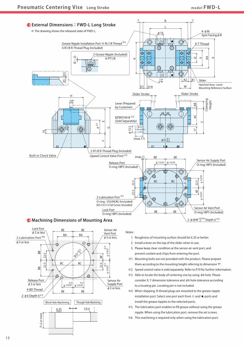
ExamplesPneumatic Centering Vise Long Stroke
External Dimensions and Machining Dimensions for Mounting
※1
AVQ
7 7B
L
φ16
K
(0 ~ 2)
W
R2 R1
U1 U
F
P G
E
HJg8
H8
10
φD-0.1-0.2
17
AE AE
CClamping
Height
External Dimensions:FWD-L Long Stroke※ The drawing shows the released state of FWD-L.
Machining Dimensions of Mounting Area
φS
ACAB
X±0.01 X±0.01
Y±0.01
Y±0.01
BE
22.5
22.5
BE
BE BE
BC BC
BF22.5
Notes :
1. Roughness of mounting surface should be 6.3S or better.
2. Install a lever on the top of the slider when in use.
3. Please keep clear condition at the sensor air vent port, and
prevent coolant and chips from entering the port.
※1. Mounting bolts are not provided with the product. Please prepare
them according to the mounting height referring to dimension 'P'.
※2. Speed control valve is sold separately. Refer to P.19 for further information.
※3. Able to locate the body of centering vise by using φ6 hole. Please
consider X, Y dimension tolerance and φ6 hole tolerance according
to a locating pin. Locating pin is not included.
※4. When shipping, R-thread plugs are mounted to the grease nipple
installation port. Select one port each from ☆ and ★ ports and
install the grease nipples to the selected ports.
※5. The lubrication port enables to fill grease without using the grease
nipple. When using the lubrication port, remove the set screws.
※6. This machining is required only when using the lubrication port.
(max.1)
C0.4
※6
※3 ※3
※3
※3
X±0.01 X±0.01
Y±0.01
Y±0.01
BA BA
BBBB
22.5
22.5
BE BE
BE BE
BC BC
BF22.5
6.3S
13
Model No.ABCDEFGHJKLMNPQR1R2S
T (Nominal×Pitch×Depth)UU1VWXYAAABACAEBABBBC
BD (Nominal×Pitch×Depth)BEBF
FWD0650-L90105598358.532.594588 74746.8113222516123
M6×1×106 1036262640472.53812373748
M6×1×104716.5
FWD0850-L11012561.5103613498.5658 929291426246.521147
M8×1.25×128 1340343547.552340.520464658
M8×1.25×125720
FWD1000-L12514063.51186339.51068010 1001051117.52826824167
M10×1.5×158 164540415559342.527.552.55065.5
M10×1.5×1564.522.5
+ 0.018 0
ー 0.005ー 0.027
ー 0.005ー 0.027
ー 0.005ー 0.027
+ 0.022 0
+ 0.022 0
Lever Mounting Part
φ15.5
(max.17)
AA
+0.30
φD
(E)0.5
※4
SliderHatched Area : Lever Mounting Reference Surface
Grease Nipple Installation Port:4-Rc1/8 Thread4-R1/8 R-Thread Plug (Included)
+0.018 0
※32-φ6H8 Depth 6
Sensor Air Vent PortO-ring:1BP5 (Included)
Sensor Air Supply PortO-ring:1BP5 (Included)
※5
Lock PortO-ring:1BP5 (Included)
2-Lubrication PortO-ring : SS5(NOK) (Included)M3×0.5×4 Set Screw (Included)
Release PortO-ring:1BP5 (Included)
※2
2-R1/8 R-Thread Plug (Included)
(Speed Control Valve Port)
※2
Lever (Preparedby Customer)
BZW0100-B(Sold Separately)
Slider Stroke Slider Stroke
4-φM
8-T Thread
Spot FacingφN
2-Grease Nipple (Included)A-PT1/8
Lock Portφ3 or less
4-BD Thread
2-Lubrication Portφ3 or less
2-φ6 Depth 6
Sensor AirVent Portφ3 or less
Release Portφ3 or less
Sensor AirSupply Portφ3 or less
※3
Blind Hole Machining Through Hole Machining
F+2 or more
(mm)
SliderHatched Area : Lever MountingReference Surface
Main Body
Built-in Check Valve

14
model FWD-LModel No. /Specifications
ActionDescription
PerformanceCurve
ExternalDimensions
Lever DesignDimensions CautionsApplication
ExamplesPneumatic Centering Vise Long Stroke
External Dimensions and Machining Dimensions for Mounting
※1
AVQ
7 7B
L
φ16
K
(0 ~ 2)
W
R2 R1
U1 U
F
P G
E
HJg8
H8
10
φD-0.1-0.2
17
AE AE
CClamping
Height
External Dimensions:FWD-L Long Stroke※ The drawing shows the released state of FWD-L.
Machining Dimensions of Mounting Area
φS
ACAB
X±0.01 X±0.01
Y±0.01
Y±0.01
BE
22.5
22.5
BE
BE BE
BC BC
BF22.5
Notes :
1. Roughness of mounting surface should be 6.3S or better.
2. Install a lever on the top of the slider when in use.
3. Please keep clear condition at the sensor air vent port, and
prevent coolant and chips from entering the port.
※1. Mounting bolts are not provided with the product. Please prepare
them according to the mounting height referring to dimension 'P'.
※2. Speed control valve is sold separately. Refer to P.19 for further information.
※3. Able to locate the body of centering vise by using φ6 hole. Please
consider X, Y dimension tolerance and φ6 hole tolerance according
to a locating pin. Locating pin is not included.
※4. When shipping, R-thread plugs are mounted to the grease nipple
installation port. Select one port each from ☆ and ★ ports and
install the grease nipples to the selected ports.
※5. The lubrication port enables to fill grease without using the grease
nipple. When using the lubrication port, remove the set screws.
※6. This machining is required only when using the lubrication port.
(max.1)
C0.4
※6
※3 ※3
※3
※3
X±0.01 X±0.01
Y±0.01
Y±0.01
BA BA
BBBB
22.5
22.5
BE BE
BE BE
BC BC
BF22.5
6.3S
13
Model No.ABCDEFGHJKLMNPQR1R2S
T (Nominal×Pitch×Depth)UU1VWXYAAABACAEBABBBC
BD (Nominal×Pitch×Depth)BEBF
FWD0650-L90105598358.532.594588 74746.8113222516123
M6×1×106 1036262640472.53812373748
M6×1×104716.5
FWD0850-L11012561.5103613498.5658 929291426246.521147
M8×1.25×128 1340343547.552340.520464658
M8×1.25×125720
FWD1000-L12514063.51186339.51068010 1001051117.52826824167
M10×1.5×158 164540415559342.527.552.55065.5
M10×1.5×1564.522.5
+ 0.018 0
ー 0.005ー 0.027
ー 0.005ー 0.027
ー 0.005ー 0.027
+ 0.022 0
+ 0.022 0
Lever Mounting Part
φ15.5
(max.17)
AA
+0.30
φD
(E)0.5
※4
SliderHatched Area : Lever Mounting Reference Surface
Grease Nipple Installation Port:4-Rc1/8 Thread4-R1/8 R-Thread Plug (Included)
+0.018 0
※32-φ6H8 Depth 6
Sensor Air Vent PortO-ring:1BP5 (Included)
Sensor Air Supply PortO-ring:1BP5 (Included)
※5
Lock PortO-ring:1BP5 (Included)
2-Lubrication PortO-ring : SS5(NOK) (Included)M3×0.5×4 Set Screw (Included)
Release PortO-ring:1BP5 (Included)
※2
2-R1/8 R-Thread Plug (Included)
(Speed Control Valve Port)
※2
Lever (Preparedby Customer)
BZW0100-B(Sold Separately)
Slider Stroke Slider Stroke
4-φM
8-T Thread
Spot FacingφN
2-Grease Nipple (Included)A-PT1/8
Lock Portφ3 or less
4-BD Thread
2-Lubrication Portφ3 or less
2-φ6 Depth 6
Sensor AirVent Portφ3 or less
Release Portφ3 or less
Sensor AirSupply Portφ3 or less
※3
Blind Hole Machining Through Hole Machining
F+2 or more
(mm)
SliderHatched Area : Lever MountingReference Surface
Main Body
Built-in Check Valve
1615
model FWDModel No. /Specifications
ActionDescription
PerformanceCurve
ExternalDimensions
Lever DesignDimensions CautionsApplication
ExamplesPneumatic Centering Vise Lever Design Dimensions
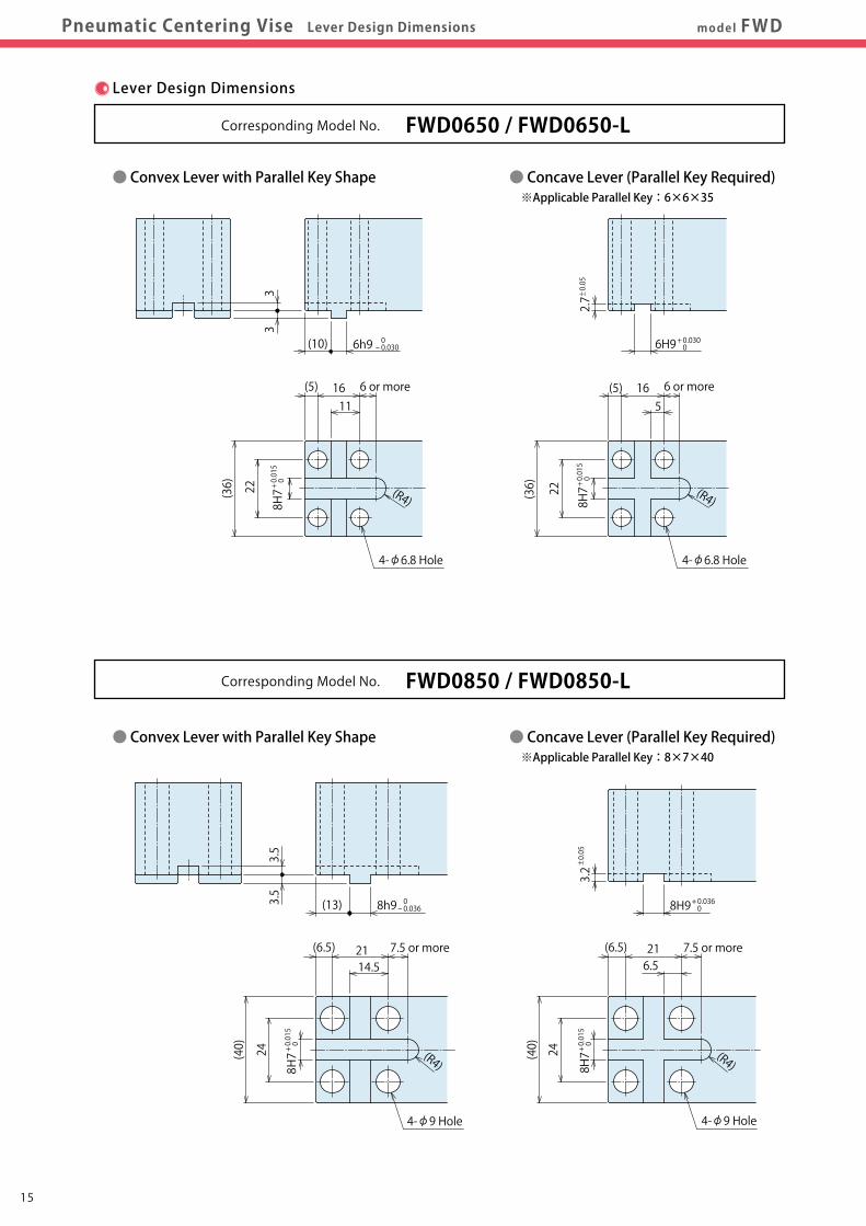
Lever Design Dimensions
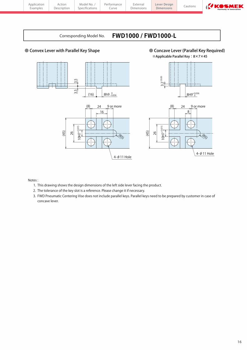
● Convex Lever with Parallel Key Shape ● Concave Lever (Parallel Key Required) ※Applicable Parallel Key:6×6×35
Corresponding Model No. FWD0650 / FWD0650-L
Corresponding Model No. FWD0850 / FWD0850-L
● Convex Lever with Parallel Key Shape ● Concave Lever (Parallel Key Required) ※Applicable Parallel Key:8×7×45
2.7
6H9
22
16 6 or more(5)
8H7 (R4)
3.2
8H9
24
21 7.5 or more(6.5)
8H7
3.2
8H9+ 0.036 0+ 0.030 0
+ 0.036 0
0- 0.036
0- 0.036
0- 0.030
+ 0.015
0
+ 0.015
0
+ 0.015
0
+ 0.015
0
+ 0.015
0
+ 0.015
0
± 0.05
± 0.05
± 0.05
(8) 9 or more24
4-φ11 Hole
10H7 (R5)
26
(R4)
5
6.5
8
(45)
(40)
(36)
33
6h9(10)
22
16 6 or more(5)
4-φ6.8 Hole 4-φ6.8 Hole
8H7 (R4)
3.5
3.5
8h9(13)
24
21 7.5 or more(6.5)
4-φ9 Hole 4-φ9 Hole
8H7
8h9(16)
(8) 9 or more24
10H7 (R5)
26
(R4)
11
14.5
16
(45)
(40)
(36)
3.5
3.5
● Convex Lever with Parallel Key Shape ● Concave Lever (Parallel Key Required) ※Applicable Parallel Key:8×7×40
Notes : 1. This drawing shows the design dimensions of the left side lever facing the product. 2. The tolerance of the key slot is a reference. Please change it if necessary. 3. FWD Pneumatic Centering Vise does not include parallel keys. Parallel keys need to be prepared by customer in case of concave lever.
Corresponding Model No. FWD1000 / FWD1000-L
4-φ11 Hole
1615
model FWDModel No. /Specifications
ActionDescription
PerformanceCurve
ExternalDimensions
Lever DesignDimensions CautionsApplication
ExamplesPneumatic Centering Vise Lever Design Dimensions
Lever Design Dimensions
● Convex Lever with Parallel Key Shape ● Concave Lever (Parallel Key Required) ※Applicable Parallel Key:6×6×35
Corresponding Model No. FWD0650 / FWD0650-L
Corresponding Model No. FWD0850 / FWD0850-L
● Convex Lever with Parallel Key Shape ● Concave Lever (Parallel Key Required) ※Applicable Parallel Key:8×7×45
2.7
6H9
22
16 6 or more(5)
8H7 (R4)
3.2
8H9
24
21 7.5 or more(6.5)
8H7
3.2
8H9+ 0.036 0+ 0.030 0
+ 0.036 0
0- 0.036
0- 0.036
0- 0.030
+ 0.015
0
+ 0.015
0
+ 0.015
0
+ 0.015
0
+ 0.015
0
+ 0.015
0
± 0.05
± 0.05
± 0.05
(8) 9 or more24
4-φ11 Hole
10H7 (R5)
26
(R4)
5
6.5
8
(45)
(40)
(36)
33
6h9(10)
22
16 6 or more(5)
4-φ6.8 Hole 4-φ6.8 Hole
8H7 (R4)
3.5
3.5
8h9(13)
24
21 7.5 or more(6.5)
4-φ9 Hole 4-φ9 Hole
8H7
8h9(16)
(8) 9 or more24
10H7 (R5)
26
(R4)
11
14.5
16
(45)
(40)
(36)
3.5
3.5
● Convex Lever with Parallel Key Shape ● Concave Lever (Parallel Key Required) ※Applicable Parallel Key:8×7×40
Notes : 1. This drawing shows the design dimensions of the left side lever facing the product. 2. The tolerance of the key slot is a reference. Please change it if necessary. 3. FWD Pneumatic Centering Vise does not include parallel keys. Parallel keys need to be prepared by customer in case of concave lever.
Corresponding Model No. FWD1000 / FWD1000-L
4-φ11 Hole
1817
model FWDModel No. /Specifications
ActionDescription
PerformanceCurve
ExternalDimensions
Lever DesignDimensions CautionsApplication
ExamplesPneumatic Centering Vise Cautions
● Notes for Design
1) Check Specifications
● Please use each product according to the specifications.
2) Notes for Circuit Design
● Please design the air circuit properly and review the circuit design
in advance in order to avoid malfunction or breakage of the device.
● Ensure there is no possibility of supplying air pressure to the lock
port and the release port simultaneously.
3)Do not apply impact on the lever (prepared by customer) when
loading a workpiece.
● Otherwise, it leads to malfunction or damage to the lever.
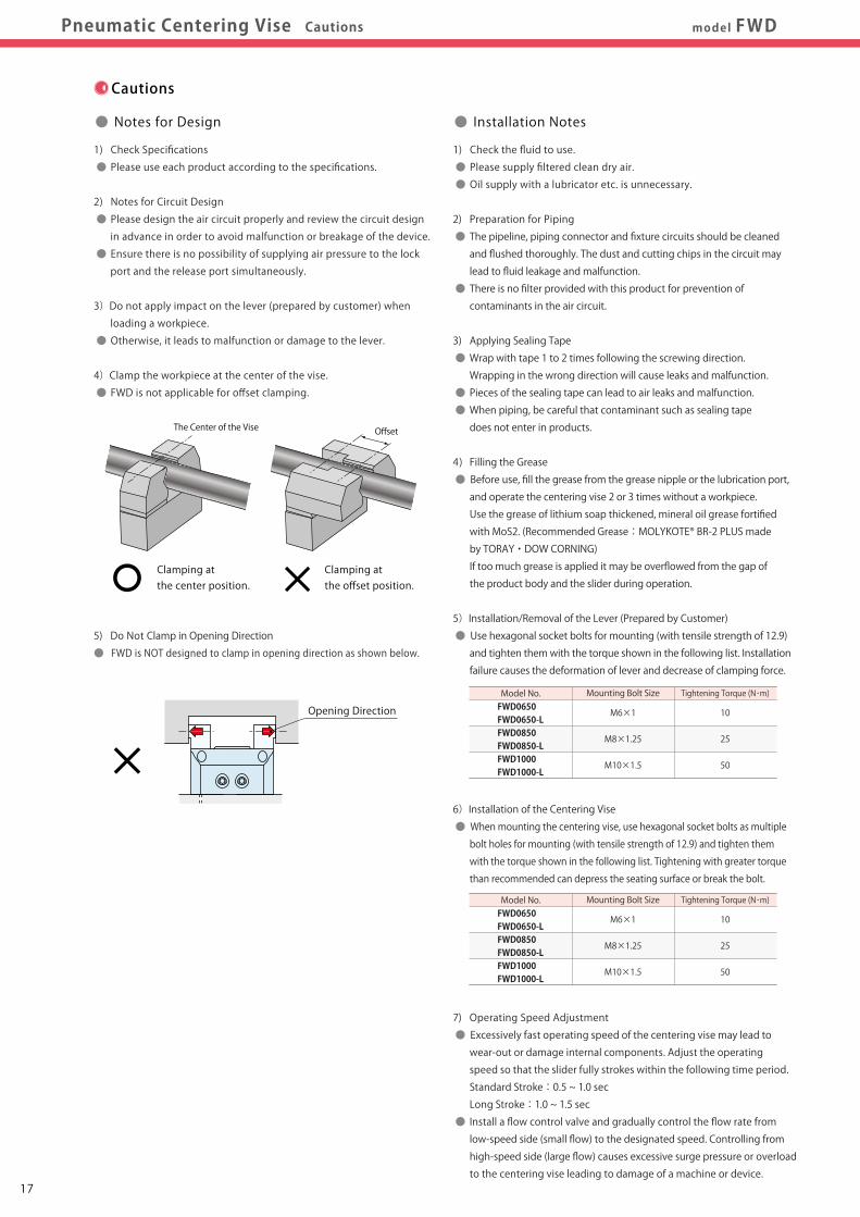
4)Clamp the workpiece at the center of the vise.
● FWD is not applicable for offset clamping.
5) Do Not Clamp in Opening Direction
● FWD is NOT designed to clamp in opening direction as shown below.
Tightening Torque (N・m)
10
25
50
Mounting Bolt Size
M6×1
M8×1.25
M10×1.5
Model No.FWD0650FWD0650-LFWD0850FWD0850-LFWD1000FWD1000-L
Tightening Torque (N・m)
10
25
50
Mounting Bolt Size
M6×1
M8×1.25
M10×1.5
Model No.FWD0650FWD0650-LFWD0850FWD0850-LFWD1000FWD1000-L
Clamping at the center position.
Clamping at the offset position.
● Installation Notes
1) Check the fluid to use.
● Please supply filtered clean dry air.
● Oil supply with a lubricator etc. is unnecessary.
2) Preparation for Piping
● The pipeline, piping connector and fixture circuits should be cleaned
and flushed thoroughly. The dust and cutting chips in the circuit may
lead to fluid leakage and malfunction.
● There is no filter provided with this product for prevention of
contaminants in the air circuit.
3) Applying Sealing Tape
● Wrap with tape 1 to 2 times following the screwing direction.
Wrapping in the wrong direction will cause leaks and malfunction.
● Pieces of the sealing tape can lead to air leaks and malfunction.
● When piping, be careful that contaminant such as sealing tape
does not enter in products.
4) Filling the Grease
● Before use, fill the grease from the grease nipple or the lubrication port,
and operate the centering vise 2 or 3 times without a workpiece.
Use the grease of lithium soap thickened, mineral oil grease fortified
with MoS2. (Recommended Grease:MOLYKOTE® BR-2 PLUS made
by TORAY・DOW CORNING)
If too much grease is applied it may be overflowed from the gap of
the product body and the slider during operation.
5)Installation/Removal of the Lever (Prepared by Customer)
● Use hexagonal socket bolts for mounting (with tensile strength of 12.9)
and tighten them with the torque shown in the following list. Installation
failure causes the deformation of lever and decrease of clamping force.
6)Installation of the Centering Vise
● When mounting the centering vise, use hexagonal socket bolts as multiple
bolt holes for mounting (with tensile strength of 12.9) and tighten them
with the torque shown in the following list. Tightening with greater torque
than recommended can depress the seating surface or break the bolt.
7) Operating Speed Adjustment
● Excessively fast operating speed of the centering vise may lead to
wear-out or damage internal components. Adjust the operating
speed so that the slider fully strokes within the following time period.
Standard Stroke:0.5 ~ 1.0 sec
Long Stroke:1.0 ~ 1.5 sec
● Install a flow control valve and gradually control the flow rate from
low-speed side (small flow) to the designated speed. Controlling from
high-speed side (large flow) causes excessive surge pressure or overload
to the centering vise leading to damage of a machine or device.
The Center of the Vise Offset
Cautions
Opening Direction
1) Warranty Period
● The product warranty period is 18 months from shipment from
our factory or 12 months from initial use, whichever is earlier.
2) Warranty Scope
● If the product is damaged or malfunctions during the warranty
period due to faulty design, materials or workmanship, we will
replace or repair the defective part at our expense.
Defects or failures caused by the following are not covered.
① If the stipulated maintenance and inspection are not carried out.
② Failure caused by the use of the non-confirming state at the user’s
discretion.
③ If it is used or handled in inappropriate way by the operator.
(Including damage caused by the misconduct of the third party.)
④ If the defect is caused by reasons other than our responsibility.
⑤ If repair or modifications are carried out by anyone other than Kosmek,
or without our approval and confirmation, it will void warranty.
⑥ Other caused by natural disasters or calamities not attributable to
our company.
⑦ Parts or replacement expenses due to parts consumption and
deterioration.
(Such as rubber, plastic, seal material and some electric components.)
Damages excluding from direct result of a product defect shall be
excluded from the warranty.
● Warranty
1) It should be operated by qualified personnel.
● Hydraulic and/or pneumatic machines and devices should be
operated and maintained by qualified personnel.
2) Do not operate or remove the product unless the safety protocols
are ensured.
① The machine and equipment can only be inspected or prepared
when it is confirmed that the safety devices are in place.
② Before removing the product, make sure that the above-mentioned
safety devices are in place. Shut off the pressure and power source,
and make sure no pressure exists in the air circuits.
③ After stopping the product, do not remove until the temperature
drops.
④ Make sure there is no trouble/issue in the bolts and respective parts
before restarting the machine or equipment.
3)Do not touch the centering vise while it is working.
Otherwise, your hands may be injured.
4)Do not disassemble or modify.
● If the product is taken apart or modified, the warranty will be
voided even within the warranty period.
1) Removal of the Product and Shut-off of Pressure Source
● Before removing the product, make sure that safety devices
and preventive devices are in place. Shut off the pressure and
power source, and make sure no pressure exists in air circuits.
● Make sure there is no abnormality in the bolts and respective
parts before restarting.
2) Regularly tighten pipes, mounting bolts, nuts and others
to ensure proper use.
3) Make sure there is a smooth action without an irregular noise.
● Especially when it is restarted after left unused for a long period,
make sure it can be operated correctly.
4) The products should be stored in the cool and dark place without
direct sunshine or moisture.
5) Regularly fill the grease from the grease nipple or the lubrication port
(recommended : once a month or every five-thousand cycles).
Use the grease of lithium soap thickened, mineral oil grease fortified
with MoS2. (Recommended Grease:MOLYKOTE® BR-2 PLUS made
by TORAY・DOW CORNING)
If too much grease is applied it may be overflowed from the gap of
the product body and the slider during operation.
6) Please contact us for overhaul and repair.
● Notes on Handling
● Maintenance and Inspection

1817
model FWDModel No. /Specifications
ActionDescription
PerformanceCurve
ExternalDimensions
Lever DesignDimensions CautionsApplication
ExamplesPneumatic Centering Vise Cautions
● Notes for Design
1) Check Specifications
● Please use each product according to the specifications.
2) Notes for Circuit Design
● Please design the air circuit properly and review the circuit design
in advance in order to avoid malfunction or breakage of the device.
● Ensure there is no possibility of supplying air pressure to the lock
port and the release port simultaneously.
3)Do not apply impact on the lever (prepared by customer) when
loading a workpiece.
● Otherwise, it leads to malfunction or damage to the lever.
4)Clamp the workpiece at the center of the vise.
● FWD is not applicable for offset clamping.
5) Do Not Clamp in Opening Direction
● FWD is NOT designed to clamp in opening direction as shown below.
Tightening Torque (N・m)
10
25
50
Mounting Bolt Size
M6×1
M8×1.25
M10×1.5
Model No.FWD0650FWD0650-LFWD0850FWD0850-LFWD1000FWD1000-L
Tightening Torque (N・m)
10
25
50
Mounting Bolt Size
M6×1
M8×1.25
M10×1.5
Model No.FWD0650FWD0650-LFWD0850FWD0850-LFWD1000FWD1000-L
Clamping at the center position.
Clamping at the offset position.
● Installation Notes
1) Check the fluid to use.
● Please supply filtered clean dry air.
● Oil supply with a lubricator etc. is unnecessary.
2) Preparation for Piping
● The pipeline, piping connector and fixture circuits should be cleaned
and flushed thoroughly. The dust and cutting chips in the circuit may
lead to fluid leakage and malfunction.
● There is no filter provided with this product for prevention of
contaminants in the air circuit.
3) Applying Sealing Tape
● Wrap with tape 1 to 2 times following the screwing direction.
Wrapping in the wrong direction will cause leaks and malfunction.
● Pieces of the sealing tape can lead to air leaks and malfunction.
● When piping, be careful that contaminant such as sealing tape
does not enter in products.
4) Filling the Grease
● Before use, fill the grease from the grease nipple or the lubrication port,
and operate the centering vise 2 or 3 times without a workpiece.
Use the grease of lithium soap thickened, mineral oil grease fortified
with MoS2. (Recommended Grease:MOLYKOTE® BR-2 PLUS made
by TORAY・DOW CORNING)
If too much grease is applied it may be overflowed from the gap of
the product body and the slider during operation.
5)Installation/Removal of the Lever (Prepared by Customer)
● Use hexagonal socket bolts for mounting (with tensile strength of 12.9)
and tighten them with the torque shown in the following list. Installation
failure causes the deformation of lever and decrease of clamping force.
6)Installation of the Centering Vise
● When mounting the centering vise, use hexagonal socket bolts as multiple
bolt holes for mounting (with tensile strength of 12.9) and tighten them
with the torque shown in the following list. Tightening with greater torque
than recommended can depress the seating surface or break the bolt.
7) Operating Speed Adjustment
● Excessively fast operating speed of the centering vise may lead to
wear-out or damage internal components. Adjust the operating
speed so that the slider fully strokes within the following time period.
Standard Stroke:0.5 ~ 1.0 sec
Long Stroke:1.0 ~ 1.5 sec
● Install a flow control valve and gradually control the flow rate from
low-speed side (small flow) to the designated speed. Controlling from
high-speed side (large flow) causes excessive surge pressure or overload
to the centering vise leading to damage of a machine or device.
The Center of the Vise Offset
Cautions
Opening Direction
1) Warranty Period
● The product warranty period is 18 months from shipment from
our factory or 12 months from initial use, whichever is earlier.
2) Warranty Scope
● If the product is damaged or malfunctions during the warranty
period due to faulty design, materials or workmanship, we will
replace or repair the defective part at our expense.
Defects or failures caused by the following are not covered.
① If the stipulated maintenance and inspection are not carried out.
② Failure caused by the use of the non-confirming state at the user’s
discretion.
③ If it is used or handled in inappropriate way by the operator.
(Including damage caused by the misconduct of the third party.)
④ If the defect is caused by reasons other than our responsibility.
⑤ If repair or modifications are carried out by anyone other than Kosmek,
or without our approval and confirmation, it will void warranty.
⑥ Other caused by natural disasters or calamities not attributable to
our company.
⑦ Parts or replacement expenses due to parts consumption and
deterioration.
(Such as rubber, plastic, seal material and some electric components.)
Damages excluding from direct result of a product defect shall be
excluded from the warranty.
● Warranty
1) It should be operated by qualified personnel.
● Hydraulic and/or pneumatic machines and devices should be
operated and maintained by qualified personnel.
2) Do not operate or remove the product unless the safety protocols
are ensured.
① The machine and equipment can only be inspected or prepared
when it is confirmed that the safety devices are in place.
② Before removing the product, make sure that the above-mentioned
safety devices are in place. Shut off the pressure and power source,
and make sure no pressure exists in the air circuits.
③ After stopping the product, do not remove until the temperature
drops.
④ Make sure there is no trouble/issue in the bolts and respective parts
before restarting the machine or equipment.
3)Do not touch the centering vise while it is working.
Otherwise, your hands may be injured.
4)Do not disassemble or modify.
● If the product is taken apart or modified, the warranty will be
voided even within the warranty period.
1) Removal of the Product and Shut-off of Pressure Source
● Before removing the product, make sure that safety devices
and preventive devices are in place. Shut off the pressure and
power source, and make sure no pressure exists in air circuits.
● Make sure there is no abnormality in the bolts and respective
parts before restarting.
2) Regularly tighten pipes, mounting bolts, nuts and others
to ensure proper use.
3) Make sure there is a smooth action without an irregular noise.
● Especially when it is restarted after left unused for a long period,
make sure it can be operated correctly.
4) The products should be stored in the cool and dark place without
direct sunshine or moisture.
5) Regularly fill the grease from the grease nipple or the lubrication port
(recommended : once a month or every five-thousand cycles).
Use the grease of lithium soap thickened, mineral oil grease fortified
with MoS2. (Recommended Grease:MOLYKOTE® BR-2 PLUS made
by TORAY・DOW CORNING)
If too much grease is applied it may be overflowed from the gap of
the product body and the slider during operation.
6) Please contact us for overhaul and repair.
● Notes on Handling
● Maintenance and Inspection

Air Flow Control Valve
2019
BZW is the flow control valve for Rc thread that enables to
mount to FWD.
It is best used in a circuit where a flow control valve cannot
be mounted or if necessary to synchronize individual speed.
Directly Mounted to Pneumatic Centering Vise
Model No. Indication
Model No.Control MethodOperating PressureWithstanding PressureAdjusting Screw Number of Rotations Tightening TorqueWeightCorresponding Model No.
MPaMPa
N・mg
BZW0100-BMeter-out0.1 ~ 1.01.5105 ~ 713
FWD□‐□
Design No.0 : Revision Number
Control MethodB : Meter-out
BZW 010 0 - B
R Thread Size010 : Rc1/8
Model BZW
Directly mounted to the pneumatic centering vise.Enables one-touch speed adjustment.
Air Flow Control Valve
Lock NutAdjusting Screw
Specifications Circuit Symbol
BZW0100-B:Meter-out
P1 PortAir Source Side(Incoming Side)
P2 PortCentering Vise Side(Outgoing Side)
External Dimensions
φ15.5
Hexagon 14
OpenClose3.54
φ11
φ8
11.5 ~ 17
KOSMEK
(Pneumatic Centering Vise)
(Rc1/8)O-ring (Included)Lock NutAdjusting Screw
Packing
Machining Dimensions of Mounting Area
φ7.8
8.8
14.8 or more
0.01 A
0.1 or lessC0.1
0.7
φ13.8
φ10 or less
45゜
6.3
φ2.5 ~ 3.5
(φ8.2)
Remove all burrs
Rc1/8 ThreadPrepared Hole 8.2
20゜
H7
6.3S
6.3S
6.3S
P1 PortAir Pressure Supply Side(Incoming Side)
A
P2 PortClamp Side(Outgoing Side)
φ0.01 A
+ 0.018
0
+ 0.1 0
±0.1
±0.02
+ 0.1 0
Flow Rate Graph
Controlled Flow Direction
←Close Adjust Screw Number of Rotations [Rotations] Open→
Flow Rate [ L/min(ANR) ]
0
20
40
60
80
100
120
0 1 2 3 4 5 6 7 8 9 10
Pressure Loss 0.4MPa
Pressure Loss 0.3MPa
Pressure Loss 0.5MPa
Pressure Loss 0.2MPa
Free Flowing Direction
Pressure Loss [MPa]
Flow Rate [ L/min(ANR) ]
0 0.1 0.2 0.3 0.4 0.5
Fully closed
Fully opened
0
20
40
60
80
100
120
Notes : 1. Since the area is sealing part, be careful not to damage it. 2. No cutting chips or burr should be at the tolerance part of machining hole. 3. As shown in the drawing, P1 port is used as the air pressure supply side and P2 port as the centering vise side.

Air Flow Control Valve
2019
BZW is the flow control valve for Rc thread that enables to
mount to FWD.
It is best used in a circuit where a flow control valve cannot
be mounted or if necessary to synchronize individual speed.
Directly Mounted to Pneumatic Centering Vise
Model No. Indication
Model No.Control MethodOperating PressureWithstanding PressureAdjusting Screw Number of Rotations Tightening TorqueWeightCorresponding Model No.
MPaMPa
N・mg
BZW0100-BMeter-out0.1 ~ 1.01.5105 ~ 713
FWD□‐□
Design No.0 : Revision Number
Control MethodB : Meter-out
BZW 010 0 - B
R Thread Size010 : Rc1/8
Model BZW
Directly mounted to the pneumatic centering vise.Enables one-touch speed adjustment.
Air Flow Control Valve
Lock NutAdjusting Screw
Specifications Circuit Symbol
BZW0100-B:Meter-out
P1 PortAir Source Side(Incoming Side)
P2 PortCentering Vise Side(Outgoing Side)
External Dimensions
φ15.5
Hexagon 14
OpenClose3.54
φ11
φ8
11.5 ~ 17
KOSMEK
(Pneumatic Centering Vise)
(Rc1/8)O-ring (Included)Lock NutAdjusting Screw
Packing
Machining Dimensions of Mounting Area
φ7.8
8.8
14.8 or more
0.01 A
0.1 or lessC0.1
0.7
φ13.8
φ10 or less
45゜
6.3
φ2.5 ~ 3.5
(φ8.2)
Remove all burrs
Rc1/8 ThreadPrepared Hole 8.2
20゜
H7
6.3S
6.3S
6.3S
P1 PortAir Pressure Supply Side(Incoming Side)
A
P2 PortClamp Side(Outgoing Side)
φ0.01 A
+ 0.018
0
+ 0.1 0
±0.1
±0.02
+ 0.1 0
Flow Rate Graph
Controlled Flow Direction
←Close Adjust Screw Number of Rotations [Rotations] Open→
Flow Rate [ L/min(ANR) ]
0
20
40
60
80
100
120
0 1 2 3 4 5 6 7 8 9 10
Pressure Loss 0.4MPa
Pressure Loss 0.3MPa
Pressure Loss 0.5MPa
Pressure Loss 0.2MPa
Free Flowing Direction
Pressure Loss [MPa]
Flow Rate [ L/min(ANR) ]
0 0.1 0.2 0.3 0.4 0.5
Fully closed
Fully opened
0
20
40
60
80
100
120
Notes : 1. Since the area is sealing part, be careful not to damage it. 2. No cutting chips or burr should be at the tolerance part of machining hole. 3. As shown in the drawing, P1 port is used as the air pressure supply side and P2 port as the centering vise side.

Model FWD
CAT.NO. SBR-FWD001-01-GBPrinted in Japan
2020/08 First PDF
▶ http://www.kosmek.com/
1-5, 2-chome, Murotani, Nishi-ku, Kobe-city, Hyogo, Japan 651-2241TEL.+81-78-991-5162 FAX.+81-78-991-8787
■ For Further Information on Unlisted Specifications and Sizes, Please call us.■ Specifications in this Leaflet are Subject to Change without Notice.
HEAD OFFICE
KOSMEK LTD.
KOSMEK (USA) LTD.650 Springer Drive, Lombard, IL 60148 USATEL. +1-630-620-7650 FAX. +1-630-620-9015
FAX. +43-463-287587-20
United States of AmericaSUBSIDIARY
KOSMEK USA Mexico Office
TEL. +52-1-55-3044-9983
MEXICOREPRESENTATIVE OFFICE
KOSMEK Thailand Representation Office67 Soi 58, RAMA 9 Rd., Phatthanakan, Suanluang, Bangkok 10250, Thailand
THAILANDREPRESENTATIVE OFFICE
KOSMEK EUROPE GmbH Schleppeplatz 2 9020 Klagenfurt am Wörthersee AustriaTEL. +43-463-287587
EUROPESUBSIDIARY
TEL.+91-9880561695
KOSMEK LTD. - INDIAF 203, Level-2, First Floor, Prestige Center Point, Cunningham Road, Bangalore -560052 India
INDIABRANCH OFFICE
FAX. +66-2-300-5133TEL. +66-2-300-5132
Av. Santa Fe 103, Int. 59, col. Santa Fe Juriquilla, Queretaro, QRO, 76230, Mexico
CHINASUBSIDIARY
TEL. +86-21-54253000
KOSMEK (CHINA) LTD.Room601, RIVERSIDE PYRAMID No.55, Lane21, Pusan Rd, Pudong Shanghai 200125, China
Pneumatic Centering ViseNew
【Built-in Check Valve】
Related Documents


