Model FVA Model FVD Model FVC Centering Vise High Accuracy, High Power, Long Stroke For Gripping Cylindrical Workpiece, and Workpiece Transfer Hand Classification Cross Section Slide Block Model Link Motion Model Compact High Power Long Stroke Long Stroke Model FVA ±0.01 mm Locating Repeatability (X-axis Direction) Features Slider Stroke (One Side) ±0.03 mm FVC0630:10 mm FVC1000:15 mm FVC1600:20 mm FVA0401:5 mm FVA0631:5 mm FVA1001:5 mm FVD1600:6 mm FVD2500:8 mm FVD4000:8 mm FVD1600-L:12 mm FVD2500-L:16 mm FVD4000-L:16 mm Accessories ・Speed Control Valve : Model BZL ・Air Bleed Valve : Model BZX ・G Thread Plug (With Air Breeding Function) : Model JZG Double Action MAX. 7 MPa Model FVC Model FVD Model FVD-L High Accuracy High Accuracy and High Power High Accuracy and Long Stroke Long Stroke of Link Motion Model Slide Block Link Lever NEW → P.891 → P.885 → P.873 → P.877 → P.877 869

Welcome message from author
This document is posted to help you gain knowledge. Please leave a comment to let me know what you think about it! Share it to your friends and learn new things together.
Transcript
Work Support
LDLCTNCTC
Swing Clamp
LHA
Pneumatic Series
Hydraulic Series
Valve / CouplerHydraulic Unit
Cautions / Others
High-PowerSeries
Manual OperationAccessories
Hole Clamp
SFASFC
Link Clamp
LKALKCLKWLM/LJTMA-2TMA-1
Block Cylinder
DBADBC
Control Valve
BZLBZTBZX/JZG
Pallet Clamp
VSVT
Expansion Locating Pin
VFLVFMVFJVFK
FPFQ
Pull Stud Clamp
FVAFVDFVC
Centering Vise
DWA/DWB
CustomizedSpring Cylinder
LHCLHSLHWLT/LGTLA-2TLB-2TLA-1
LLW
Air SensingLift Cylinder
Compact Cylinder
LLLLRLLUDPDRDSDT
Introduction ApplicationExamples
ActionDescription Cautions
Model FVAModel No. IndicationSpecifications・External Dimensions
Model FVDModel No. IndicationSpecifications・External Dimensions
Model FVCModel No. IndicationSpecifications・External Dimensions
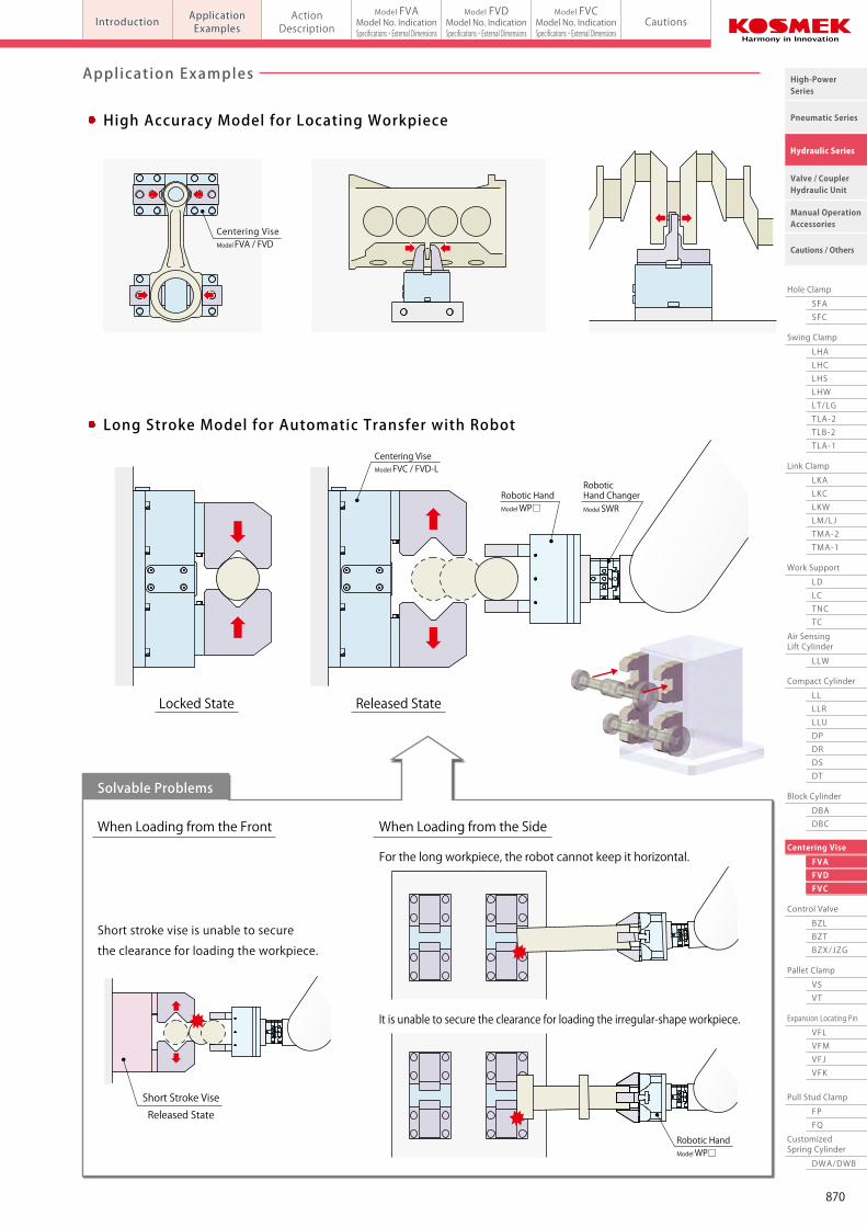
Application Examples
Short stroke vise is unable to secure
the clearance for loading the workpiece.
When Loading from the Front
Solvable Problems
When Loading from the Side
For the long workpiece, the robot cannot keep it horizontal.
It is unable to secure the clearance for loading the irregular-shape workpiece.
Locked State Released State
Robotic Hand ChangerModel SWR
Robotic HandModel WP□
Short Stroke ViseReleased State
Long Stroke Model for Automatic Transfer with Robot
Centering ViseModel FVC / FVD-L
Robotic HandModel WP□
Model FVAModel FVDModel FVC
Centering Vise
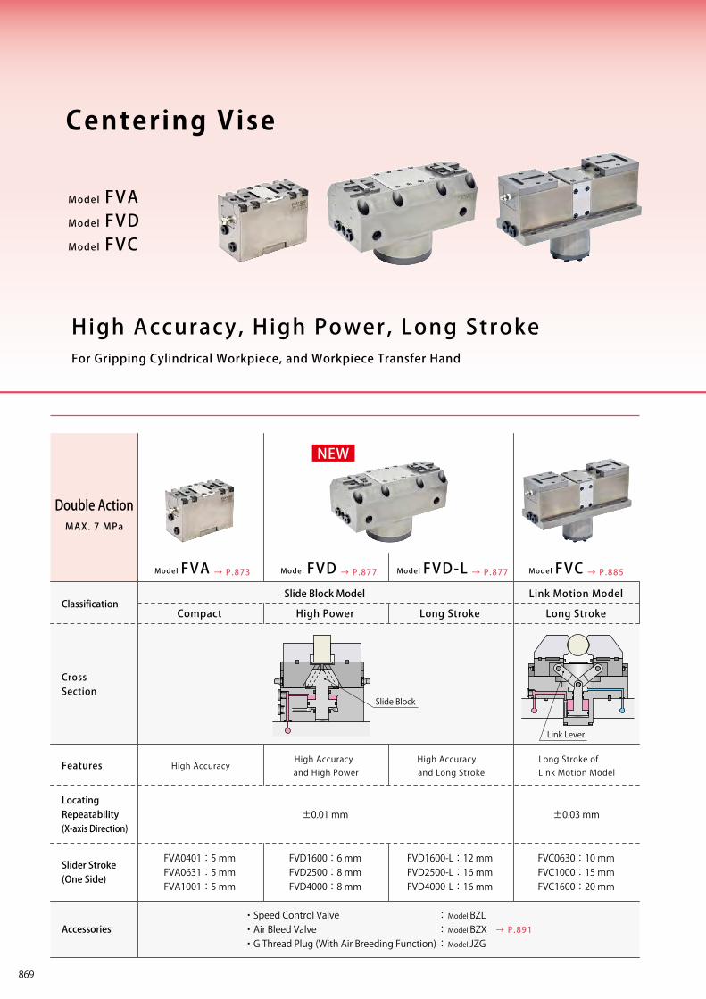
High Accuracy, High Power, Long StrokeFor Gripping Cylindrical Workpiece, and Workpiece Transfer Hand
Classification
CrossSection
Slide Block Model Link Motion Model
Compact High Power Long Stroke Long Stroke
Model FVA
±0.01 mmLocating Repeatability(X-axis Direction)
Features
Slider Stroke(One Side)
±0.03 mm
FVC0630:10 mmFVC1000:15 mmFVC1600:20 mm
FVA0401:5 mmFVA0631:5 mmFVA1001:5 mm
FVD1600:6 mmFVD2500:8 mmFVD4000:8 mm
FVD1600-L:12 mmFVD2500-L:16 mmFVD4000-L:16 mm
Accessories・Speed Control Valve : Model BZL・Air Bleed Valve : Model BZX・G Thread Plug (With Air Breeding Function) : Model JZG
Double ActionMAX. 7 MPa
Model FVCModel FVD Model FVD-L
High Accuracy Model for Locating Workpiece
High AccuracyHigh Accuracy and High Power
High Accuracy and Long Stroke
Long Stroke of Link Motion Model
Centering ViseModel FVA / FVD
Slide Block
Link Lever
NEW
→ P.891
→ P.885→ P.873 → P.877 → P.877
869
Work Support
LDLCTNCTC
Swing Clamp
LHA
Pneumatic Series
Hydraulic Series
Valve / CouplerHydraulic Unit
Cautions / Others
High-PowerSeries
Manual OperationAccessories
Hole Clamp
SFASFC
Link Clamp
LKALKCLKWLM/LJTMA-2TMA-1
Block Cylinder
DBADBC
Control Valve
BZLBZTBZX/JZG
Pallet Clamp
VSVT
Expansion Locating Pin
VFLVFMVFJVFK
FPFQ
Pull Stud Clamp
FVAFVDFVC
Centering Vise
DWA/DWB
CustomizedSpring Cylinder
LHCLHSLHWLT/LGTLA-2TLB-2TLA-1
LLW
Air SensingLift Cylinder
Compact Cylinder
LLLLRLLUDPDRDSDT
Introduction ApplicationExamples
ActionDescription Cautions
Model FVAModel No. IndicationSpecifications・External Dimensions
Model FVDModel No. IndicationSpecifications・External Dimensions
Model FVCModel No. IndicationSpecifications・External Dimensions
Application Examples
Short stroke vise is unable to secure
the clearance for loading the workpiece.
When Loading from the Front
Solvable Problems
When Loading from the Side
For the long workpiece, the robot cannot keep it horizontal.
It is unable to secure the clearance for loading the irregular-shape workpiece.
Locked State Released State
Robotic Hand ChangerModel SWR
Robotic HandModel WP□
Short Stroke ViseReleased State
Long Stroke Model for Automatic Transfer with Robot
Centering ViseModel FVC / FVD-L
Robotic HandModel WP□
Model FVAModel FVDModel FVC
Centering Vise
High Accuracy, High Power, Long StrokeFor Gripping Cylindrical Workpiece, and Workpiece Transfer Hand
Classification
CrossSection
Slide Block Model Link Motion Model
Compact High Power Long Stroke Long Stroke
Model FVA
±0.01 mmLocating Repeatability(X-axis Direction)
Features
Slider Stroke(One Side)
±0.03 mm
FVC0630:10 mmFVC1000:15 mmFVC1600:20 mm
FVA0401:5 mmFVA0631:5 mmFVA1001:5 mm
FVD1600:6 mmFVD2500:8 mmFVD4000:8 mm
FVD1600-L:12 mmFVD2500-L:16 mmFVD4000-L:16 mm
Accessories・Speed Control Valve : Model BZL・Air Bleed Valve : Model BZX・G Thread Plug (With Air Breeding Function) : Model JZG
Double ActionMAX. 7 MPa
Model FVCModel FVD Model FVD-L
High Accuracy Model for Locating Workpiece
High AccuracyHigh Accuracy and High Power
High Accuracy and Long Stroke
Long Stroke of Link Motion Model
Centering ViseModel FVA / FVD
Slide Block
Link Lever
NEW
→ P.891
→ P.885→ P.873 → P.877 → P.877
870
Work Support
LDLCTNCTC
Swing Clamp
LHA
Pneumatic Series
Hydraulic Series
Valve / CouplerHydraulic Unit
Cautions / Others
High-PowerSeries
Manual OperationAccessories
Hole Clamp
SFASFC
Link Clamp
LKALKCLKWLM/LJTMA-2TMA-1
Block Cylinder
DBADBC
Control Valve
BZLBZTBZX/JZG
Pallet Clamp
VSVT
Expansion Locating Pin
VFLVFMVFJVFK
FPFQ
Pull Stud Clamp
FVAFVDFVC
Centering Vise
DWA/DWB
CustomizedSpring Cylinder
LHCLHSLHWLT/LGTLA-2TLB-2TLA-1
LLW
Air SensingLift Cylinder
Compact Cylinder
LLLLRLLUDPDRDSDT
Introduction ApplicationExamples
ActionDescription Cautions
Model FVAModel No. IndicationSpecifications・External Dimensions
Model FVDModel No. IndicationSpecifications・External Dimensions
Model FVCModel No. IndicationSpecifications・External Dimensionsmodel FVA/FVD/FVCCentering Vise
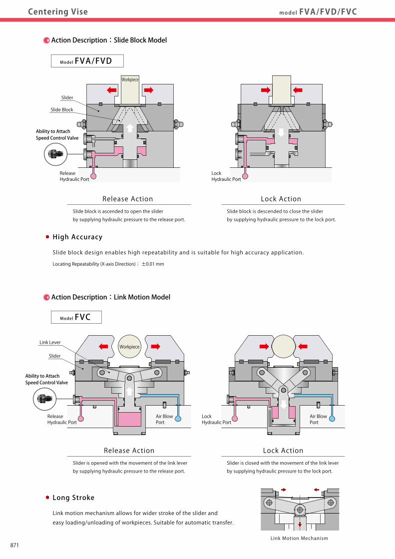
Action Description:Slide Block Model
Action Description:Link Motion Model
Model FVC
Release Action
Slider is opened with the movement of the link lever
by supplying hydraulic pressure to the release port.
Lock Action
Model FVA/FVD
Slider is closed with the movement of the link lever
by supplying hydraulic pressure to the lock port.
Release Action
Slide block is ascended to open the slider
by supplying hydraulic pressure to the release port.
Lock Action
Slide block is descended to close the slider
by supplying hydraulic pressure to the lock port.
ReleaseHydraulic Port
LockHydraulic Port
ReleaseHydraulic Port
Workpiece
Slider
Workpiece
LockHydraulic Port
Air BlowPort
Air BlowPort
Long Stroke
Link motion mechanism allows for wider stroke of the slider and
easy loading/unloading of workpieces. Suitable for automatic transfer.
High Accuracy
Slide block design enables high repeatability and is suitable for high accuracy application.
Link Motion Mechanism
Locating Repeatability (X-axis Direction): ±0.01 mm
Slide Block
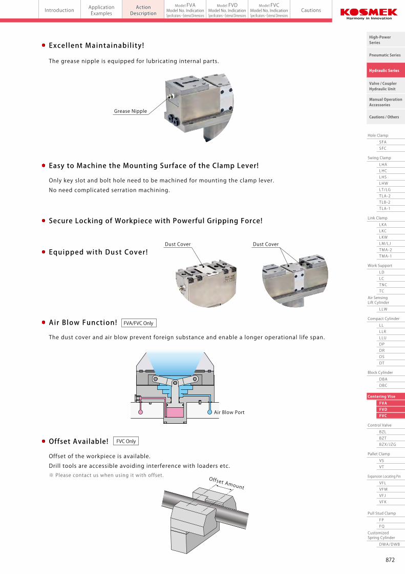
Air Blow Function!
The dust cover and air blow prevent foreign substance and enable a longer operational l ife span.
Excel lent Maintainabil ity!
The grease nipple is equipped for lubricating internal parts.
Equipped with Dust Cover!Dust CoverDust Cover
Grease Nipple
Offset Amount
Easy to Machine the Mounting Surface of the Clamp Lever!
Secure Locking of Workpiece with Powerful Gripping Force!
Offset Available!
Only key slot and bolt hole need to be machined for mounting the clamp lever.
No need complicated serration machining.
Offset of the workpiece is available.
Drill tools are accessible avoiding interference with loaders etc.※ Please contact us when using it with offset.
FVA/FVC Only
FVC Only
Slider
Link Lever
Ability to Attach Speed Control Valve
Ability to Attach Speed Control Valve
Air Blow Port
871
Work Support
LDLCTNCTC
Swing Clamp
LHA
Pneumatic Series
Hydraulic Series
Valve / CouplerHydraulic Unit
Cautions / Others
High-PowerSeries
Manual OperationAccessories
Hole Clamp
SFASFC
Link Clamp
LKALKCLKWLM/LJTMA-2TMA-1
Block Cylinder
DBADBC
Control Valve
BZLBZTBZX/JZG
Pallet Clamp
VSVT
Expansion Locating Pin
VFLVFMVFJVFK
FPFQ
Pull Stud Clamp
FVAFVDFVC
Centering Vise
DWA/DWB
CustomizedSpring Cylinder
LHCLHSLHWLT/LGTLA-2TLB-2TLA-1
LLW
Air SensingLift Cylinder
Compact Cylinder
LLLLRLLUDPDRDSDT
Introduction ApplicationExamples
ActionDescription Cautions
Model FVAModel No. IndicationSpecifications・External Dimensions
Model FVDModel No. IndicationSpecifications・External Dimensions
Model FVCModel No. IndicationSpecifications・External Dimensionsmodel FVA/FVD/FVCCentering Vise
Action Description:Slide Block Model
Action Description:Link Motion Model
Model FVC
Release Action
Slider is opened with the movement of the link lever
by supplying hydraulic pressure to the release port.
Lock Action
Model FVA/FVD
Slider is closed with the movement of the link lever
by supplying hydraulic pressure to the lock port.
Release Action
Slide block is ascended to open the slider
by supplying hydraulic pressure to the release port.
Lock Action
Slide block is descended to close the slider
by supplying hydraulic pressure to the lock port.
ReleaseHydraulic Port
LockHydraulic Port
ReleaseHydraulic Port
Workpiece
Slider
Workpiece
LockHydraulic Port
Air BlowPort
Air BlowPort
Long Stroke
Link motion mechanism allows for wider stroke of the slider and
easy loading/unloading of workpieces. Suitable for automatic transfer.
High Accuracy
Slide block design enables high repeatability and is suitable for high accuracy application.
Link Motion Mechanism
Locating Repeatability (X-axis Direction): ±0.01 mm
Slide Block
Air Blow Function!
The dust cover and air blow prevent foreign substance and enable a longer operational l ife span.
Excel lent Maintainabil ity!
The grease nipple is equipped for lubricating internal parts.
Equipped with Dust Cover!Dust CoverDust Cover
Grease Nipple
Offset Amount
Easy to Machine the Mounting Surface of the Clamp Lever!
Secure Locking of Workpiece with Powerful Gripping Force!
Offset Available!
Only key slot and bolt hole need to be machined for mounting the clamp lever.
No need complicated serration machining.
Offset of the workpiece is available.
Drill tools are accessible avoiding interference with loaders etc.※ Please contact us when using it with offset.
FVA/FVC Only
FVC Only
Slider
Link Lever
Ability to Attach Speed Control Valve
Ability to Attach Speed Control Valve
Air Blow Port
872
Work Support
LDLCTNCTC
Swing Clamp
LHA
Pneumatic Series
Hydraulic Series
Valve / CouplerHydraulic Unit
Cautions / Others
High-PowerSeries
Manual OperationAccessories
Hole Clamp
SFASFC
Link Clamp
LKALKCLKWLM/LJTMA-2TMA-1
Block Cylinder
DBADBC
Control Valve
BZLBZTBZX/JZG
Pallet Clamp
VSVT
Expansion Locating Pin
VFLVFMVFJVFK
FPFQ
Pull Stud Clamp
FVAFVDFVC
Centering Vise
DWA/DWB
CustomizedSpring Cylinder
LHCLHSLHWLT/LGTLA-2TLB-2TLA-1
LLW
Air SensingLift Cylinder
Compact Cylinder
LLLLRLLUDPDRDSDT
Introduction ApplicationExamples
ActionDescription Cautions
Model FVAModel No. IndicationSpecifications・External Dimensions
Model FVDModel No. IndicationSpecifications・External Dimensions
Model FVCModel No. IndicationSpecifications・External Dimensionsmodel FVACentering Vise Slide Block Model (Compact)
Model No. Indication Clamping Force Curve
L=30 mmL=0 mm
L=50 mmL=70 mmL=90 mm
L=30 mm
L=0 mm
L=0 mm
L=50 mmL=70 mmL=90 mm
L=30 mmL=50 mmL=70 mmL=90 mm
P:Hydraulic Pressure (MPa)
P:Hydraulic Pressure (MPa)
P:Hydraulic Pressure (MPa)
F:Clamping Force (kN)
F:Clamping Force (kN)
F:Clamping Force (kN)
0
1
2
3
4
5
0 1 2 3 4 5 6 7
0
2
4
6
8
10
0 1 2 3 4 5 6 7
0
2
4
6
8
10
12
14
0 1 2 3 4 5 6 7
Non-Usable Range (■)
Non-Usable Range (■)
Non-Usable Range (■)
L : Clamping Height (mm)
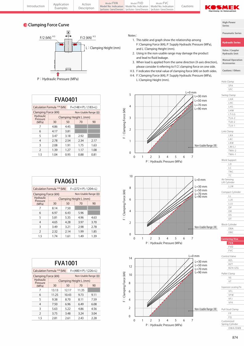
7 6 5 4 3 2 1.5
FVA0401Calculation Formula ※4 (kN) F=(148×P) / (183+L)
Clamping Height L (mm)
Clamping Force (kN) Non-Usable Range (■)
7 6 5 4 3 2 1.5
FVA0631Calculation Formula ※4 (kN) F=(272×P) / (204+L)
Clamping Height L (mm)
Non-Usable Range (■)
7 6 5 4 3 2 1.5
FVA1001Calculation Formula ※4 (kN) F=(480×P) / (226+L)
Clamping Height L (mm)
Non-Usable Range (■)
HydraulicPressure(MPa)
HydraulicPressure(MPa)
HydraulicPressure(MPa)
Clamping Force (kN)
Clamping Force (kN)
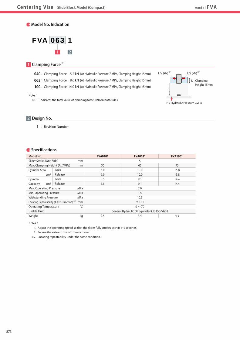
Specifications
2
1 : Revision Number
Design No.
1 2
FVA 063 1
Model No. Slider Stroke (One Side) Max. Clamping Height (At 7MPa) Cylinder Area
Cylinder Capacity Max. Operating Pressure Min. Operating Pressure Withstanding Pressure Locating Repeatability (X-axis Direction) Operating Temperature Usable Fluid Weight
FVA0401
506.06.05.55.5
2.5
FVA063156510.010.09.19.17.01.510.5±0.010 ~ 70
General Hydraulic Oil Equivalent to ISO-VG323.4
FVA1001
7515.815.814.414.4
4.3
mmmm
MPaMPaMPamm℃
kg
Notes: 1. Adjust the operating speed so that the slider fully strokes within 1~2 seconds. 2. Secure the extra stroke of 1mm or more. ※2. Locating repeatability under the same condition.
※2
Lock Release Lock Releasecm3
cm2
1 Clamping Force
040 : Clamping Force 5.2 kN (At Hydraulic Pressure 7 MPa, Clamping Height 15mm)
063 : Clamping Force 8.6 kN (At Hydraulic Pressure 7 MPa, Clamping Height 15mm)
100 : Clamping Force 14.0 kN (At Hydraulic Pressure 7 MPa, Clamping Height 15mm)
Note: ※1. F indicates the total value of clamping force (kN) on both sides.
※1
Notes: 1. This table and graph show the relationship among F:Clamping Force (kN), P:Supply Hydraulic Pressure (MPa), and L:Clamping Height (mm). 2. Using in the non-usable range may damage the product and lead to fluid leakage. 3. When load is applied from the same direction (X-axis direction), please consider it referring to F/2:clamping force on one side. ※3. F indicates the total value of clamping force (kN) on both sides. ※4. F:Clamping Force (kN), P:Supply Hydraulic Pressure (MPa), L:Clamping Height (mm). P : Hydraulic Pressure (MPa)
L : Clamping Height 15mm
P : Hydraulic Pressure 7MPa
※1F/2 (kN) ※1F/2 (kN)
※3F/2 (kN)※3F/2 (kN)X
304.864.173.472.782.081.391.04
504.453.813.182.541.911.270.95
70
2.922.341.751.170.88
90
2.171.631.080.81
308.146.975.814.653.492.321.74
507.506.435.354.283.212.141.61
70
5.964.963.972.981.991.49
90
4.633.702.781.851.39
3013.1311.259.387.505.633.752.81
5012.1710.438.706.965.223.482.61
7011.359.738.116.494.863.242.43
90
9.117.596.084.563.042.28
873
Work Support
LDLCTNCTC
Swing Clamp
LHA
Pneumatic Series
Hydraulic Series
Valve / CouplerHydraulic Unit
Cautions / Others
High-PowerSeries
Manual OperationAccessories
Hole Clamp
SFASFC
Link Clamp
LKALKCLKWLM/LJTMA-2TMA-1
Block Cylinder
DBADBC
Control Valve
BZLBZTBZX/JZG
Pallet Clamp
VSVT
Expansion Locating Pin
VFLVFMVFJVFK
FPFQ
Pull Stud Clamp
FVAFVDFVC
Centering Vise
DWA/DWB
CustomizedSpring Cylinder
LHCLHSLHWLT/LGTLA-2TLB-2TLA-1
LLW
Air SensingLift Cylinder
Compact Cylinder
LLLLRLLUDPDRDSDT
Introduction ApplicationExamples
ActionDescription Cautions
Model FVAModel No. IndicationSpecifications・External Dimensions
Model FVDModel No. IndicationSpecifications・External Dimensions
Model FVCModel No. IndicationSpecifications・External Dimensionsmodel FVACentering Vise Slide Block Model (Compact)
Model No. Indication Clamping Force Curve
L=30 mmL=0 mm
L=50 mmL=70 mmL=90 mm
L=30 mm
L=0 mm
L=0 mm
L=50 mmL=70 mmL=90 mm
L=30 mmL=50 mmL=70 mmL=90 mm
P:Hydraulic Pressure (MPa)
P:Hydraulic Pressure (MPa)
P:Hydraulic Pressure (MPa)
F:Clamping Force (kN)
F:Clamping Force (kN)
F:Clamping Force (kN)
0
1
2
3
4
5
0 1 2 3 4 5 6 7
0
2
4
6
8
10
0 1 2 3 4 5 6 7
0
2
4
6
8
10
12
14
0 1 2 3 4 5 6 7
Non-Usable Range (■)
Non-Usable Range (■)
Non-Usable Range (■)
L : Clamping Height (mm)
7 6 5 4 3 2 1.5
FVA0401Calculation Formula ※4 (kN) F=(148×P) / (183+L)
Clamping Height L (mm)
Clamping Force (kN) Non-Usable Range (■)
7 6 5 4 3 2 1.5
FVA0631Calculation Formula ※4 (kN) F=(272×P) / (204+L)
Clamping Height L (mm)
Non-Usable Range (■)
7 6 5 4 3 2 1.5
FVA1001Calculation Formula ※4 (kN) F=(480×P) / (226+L)
Clamping Height L (mm)
Non-Usable Range (■)
HydraulicPressure(MPa)
HydraulicPressure(MPa)
HydraulicPressure(MPa)
Clamping Force (kN)
Clamping Force (kN)
Specifications
2
1 : Revision Number
Design No.
1 2
FVA 063 1
Model No. Slider Stroke (One Side) Max. Clamping Height (At 7MPa) Cylinder Area
Cylinder Capacity Max. Operating Pressure Min. Operating Pressure Withstanding Pressure Locating Repeatability (X-axis Direction) Operating Temperature Usable Fluid Weight
FVA0401
506.06.05.55.5
2.5
FVA063156510.010.09.19.17.01.510.5±0.010 ~ 70
General Hydraulic Oil Equivalent to ISO-VG323.4
FVA1001
7515.815.814.414.4
4.3
mmmm
MPaMPaMPamm℃
kg
Notes: 1. Adjust the operating speed so that the slider fully strokes within 1~2 seconds. 2. Secure the extra stroke of 1mm or more. ※2. Locating repeatability under the same condition.
※2
Lock Release Lock Releasecm3
cm2
1 Clamping Force
040 : Clamping Force 5.2 kN (At Hydraulic Pressure 7 MPa, Clamping Height 15mm)
063 : Clamping Force 8.6 kN (At Hydraulic Pressure 7 MPa, Clamping Height 15mm)
100 : Clamping Force 14.0 kN (At Hydraulic Pressure 7 MPa, Clamping Height 15mm)
Note: ※1. F indicates the total value of clamping force (kN) on both sides.
※1
Notes: 1. This table and graph show the relationship among F:Clamping Force (kN), P:Supply Hydraulic Pressure (MPa), and L:Clamping Height (mm). 2. Using in the non-usable range may damage the product and lead to fluid leakage. 3. When load is applied from the same direction (X-axis direction), please consider it referring to F/2:clamping force on one side. ※3. F indicates the total value of clamping force (kN) on both sides. ※4. F:Clamping Force (kN), P:Supply Hydraulic Pressure (MPa), L:Clamping Height (mm). P : Hydraulic Pressure (MPa)
L : Clamping Height 15mm
P : Hydraulic Pressure 7MPa
※1F/2 (kN) ※1F/2 (kN)
※3F/2 (kN)※3F/2 (kN)X
304.864.173.472.782.081.391.04
504.453.813.182.541.911.270.95
70
2.922.341.751.170.88
90
2.171.631.080.81
308.146.975.814.653.492.321.74
507.506.435.354.283.212.141.61
70
5.964.963.972.981.991.49
90
4.633.702.781.851.39
3013.1311.259.387.505.633.752.81
5012.1710.438.706.965.223.482.61
7011.359.738.116.494.863.242.43
90
9.117.596.084.563.042.28
874
Work Support
LDLCTNCTC
Swing Clamp
LHA
Pneumatic Series
Hydraulic Series
Valve / CouplerHydraulic Unit
Cautions / Others
High-PowerSeries
Manual OperationAccessories
Hole Clamp
SFASFC
Link Clamp
LKALKCLKWLM/LJTMA-2TMA-1
Block Cylinder
DBADBC
Control Valve
BZLBZTBZX/JZG
Pallet Clamp
VSVT
Expansion Locating Pin
VFLVFMVFJVFK
FPFQ
Pull Stud Clamp
FVAFVDFVC
Centering Vise
DWA/DWB
CustomizedSpring Cylinder
LHCLHSLHWLT/LGTLA-2TLB-2TLA-1
LLW
Air SensingLift Cylinder
Compact Cylinder
LLLLRLLUDPDRDSDT
Introduction ApplicationExamples
ActionDescription Cautions
Model FVAModel No. IndicationSpecifications・External Dimensions
Model FVDModel No. IndicationSpecifications・External Dimensions
Model FVCModel No. IndicationSpecifications・External Dimensionsmodel FVACentering Vise Slide Block Model (Compact)
T±0.1 T±0.1
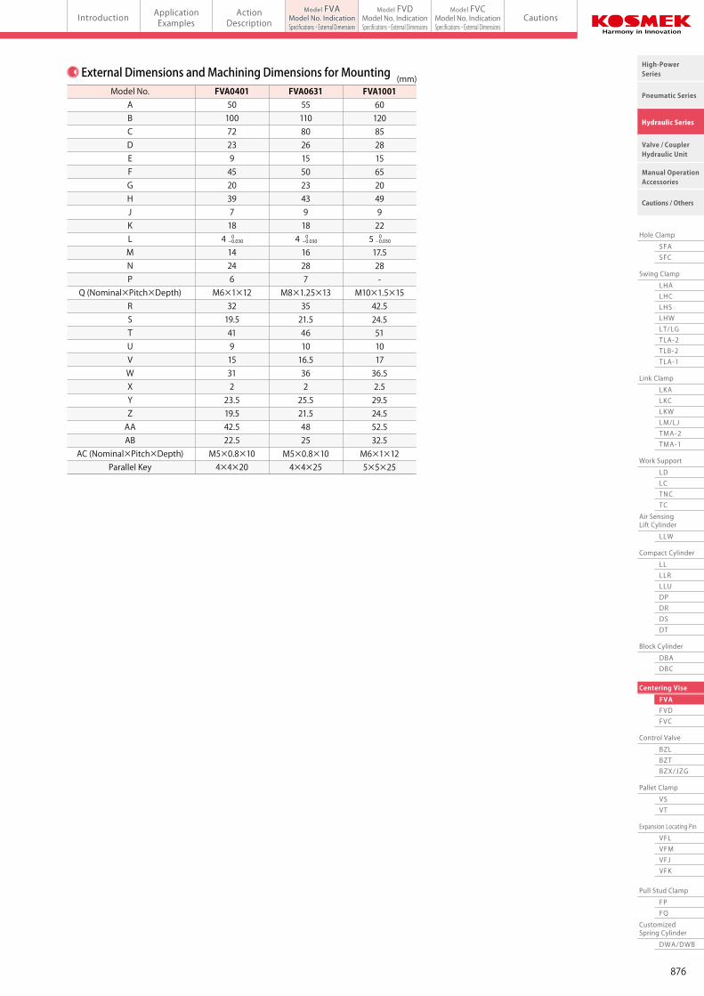
Model No.ABCDEFGHJKLMNP
Q (Nominal×Pitch×Depth)RSTUVWXYZAAAB
AC (Nominal×Pitch×Depth)Parallel Key
FVA040150100722394520397184 14246
M6×1×123219.54191531223.519.542.522.5
M5×0.8×104×4×20
FVA0631551108026155023439184 16287
M8×1.25×133521.5461016.536225.521.54825
M5×0.8×104×4×25
FVA1001601208528156520499225 17.528-
M10×1.5×1542.524.551101736.52.529.524.552.532.5
M6×1×125×5×25
(mm)
0- 0.030
0- 0.030
0- 0.030
External Dimensions and Machining Dimensions for Mounting
★
★
★
★
★
★
★
★
Release Port
AB ABAA AA
8-φ9 Through Hole
Clamping Height
5C
AD
J K M
5 (Slider Stroke)
T
R R
SSU
U
G F G
B(E)8-φ5.5
Spot Facingφ9 Depth P
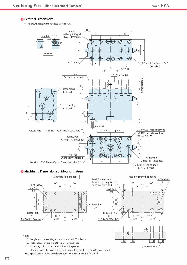
Release PortO-ring 1BP7 (Included)
O-ring 1BP7 (Included)Lock Port
8-M8×1.25 Thread Depth 15
2-Parallel Key (Square End)(Included)
2-Parallel Pin (Included)φ5×10 (B Type)
φ5 or less
3.5
φ14W
V
2-Grease Nipple(Included)
HY
X
4- Q Screw
5.5N
5.5Lever
(Prepared by Customer)
11
11 R5.5
8-φ6.8
8
FVA1001
(Except FVA1001)Z
ZUU
ZZ
UU
R R
AB ABAA AA
S
T
8-AC ScrewLock Port
φ5
φ52-φ5H8 Depth 6
±0.01
±0.01
±0.01 ±0.01
±0.01 ±0.01
±0.1R RT
±0.01 ±0.01
±0.1
±0.01
S±0.01
S±0.01
S±0.01
External Dimensions
Machining Dimensions of Mounting Area
※ The drawing shows the released state of FVA.
+ 0.018 0
Release Port:G1/8 Thread (Speed Control Valve Port)
Lock Port:G1/8 Thread (Speed Control Valve Port)
2-G Thread Plug
Mounting from the Top Mounting from the Bottom
(Mounting Bolt)
Release Portφ5
6.3S
Lock Portφ5
X
(Slot Width)LN9
※2
※1
※2
(Included)
2-φ5H8 Depth 6+ 0.018 0
FVA0401 has only four holes marked with ★.
FVA0401 has only fourholes marked with ★.
Notes: 1. Roughness of mounting surface should be 6.3S or better. 2. Install a lever on the top of the slider when in use. ※1. Mounting bolts are not provided with the product. Please prepare them according to the mounting height referring to dimension 'C'. ※2. Speed control valve is sold separately. Please refer to P.891 for detail.
T
Air Blow PortO-ring 1BP7 (Included)
Air Blow Portφ5
Air Blow Portφ5
875
Work Support
LDLCTNCTC
Swing Clamp
LHA
Pneumatic Series
Hydraulic Series
Valve / CouplerHydraulic Unit
Cautions / Others
High-PowerSeries
Manual OperationAccessories
Hole Clamp
SFASFC
Link Clamp
LKALKCLKWLM/LJTMA-2TMA-1
Block Cylinder
DBADBC
Control Valve
BZLBZTBZX/JZG
Pallet Clamp
VSVT
Expansion Locating Pin
VFLVFMVFJVFK
FPFQ
Pull Stud Clamp
FVAFVDFVC
Centering Vise
DWA/DWB
CustomizedSpring Cylinder
LHCLHSLHWLT/LGTLA-2TLB-2TLA-1
LLW
Air SensingLift Cylinder
Compact Cylinder
LLLLRLLUDPDRDSDT
Introduction ApplicationExamples
ActionDescription Cautions
Model FVAModel No. IndicationSpecifications・External Dimensions
Model FVDModel No. IndicationSpecifications・External Dimensions
Model FVCModel No. IndicationSpecifications・External Dimensionsmodel FVACentering Vise Slide Block Model (Compact)
T±0.1 T±0.1
Model No.ABCDEFGHJKLMNP
Q (Nominal×Pitch×Depth)RSTUVWXYZAAAB
AC (Nominal×Pitch×Depth)Parallel Key
FVA040150100722394520397184 14246
M6×1×123219.54191531223.519.542.522.5
M5×0.8×104×4×20
FVA0631551108026155023439184 16287
M8×1.25×133521.5461016.536225.521.54825
M5×0.8×104×4×25
FVA1001601208528156520499225 17.528-
M10×1.5×1542.524.551101736.52.529.524.552.532.5
M6×1×125×5×25
(mm)
0- 0.030
0- 0.030
0- 0.030
External Dimensions and Machining Dimensions for Mounting
★
★
★
★
★
★
★
★
Release Port
AB ABAA AA
8-φ9 Through Hole
Clamping Height
5C
AD
J K M
5 (Slider Stroke)
T
R R
SSU
U
G F G
B(E)8-φ5.5
Spot Facingφ9 Depth P
Release PortO-ring 1BP7 (Included)
O-ring 1BP7 (Included)Lock Port
8-M8×1.25 Thread Depth 15
2-Parallel Key (Square End)(Included)
2-Parallel Pin (Included)φ5×10 (B Type)
φ5 or less
3.5
φ14W
V
2-Grease Nipple(Included)
HY
X
4- Q Screw
5.5N
5.5Lever
(Prepared by Customer)
11
11 R5.5
8-φ6.8
8
FVA1001
(Except FVA1001)
ZZ
UU
ZZ
UU
R R
AB ABAA AA
S
T
8-AC ScrewLock Port
φ5
φ52-φ5H8 Depth 6
±0.01
±0.01
±0.01 ±0.01
±0.01 ±0.01
±0.1R RT
±0.01 ±0.01
±0.1
±0.01
S±0.01
S±0.01
S±0.01
External Dimensions
Machining Dimensions of Mounting Area
※ The drawing shows the released state of FVA.
+ 0.018 0
Release Port:G1/8 Thread (Speed Control Valve Port)
Lock Port:G1/8 Thread (Speed Control Valve Port)
2-G Thread Plug
Mounting from the Top Mounting from the Bottom
(Mounting Bolt)
Release Portφ5
6.3S
Lock Portφ5
X
(Slot Width)LN9
※2
※1
※2
(Included)
2-φ5H8 Depth 6+ 0.018 0
FVA0401 has only four holes marked with ★.
FVA0401 has only fourholes marked with ★.
Notes: 1. Roughness of mounting surface should be 6.3S or better. 2. Install a lever on the top of the slider when in use. ※1. Mounting bolts are not provided with the product. Please prepare them according to the mounting height referring to dimension 'C'. ※2. Speed control valve is sold separately. Please refer to P.891 for detail.
T
Air Blow PortO-ring 1BP7 (Included)
876
Work Support
LDLCTNCTC
Swing Clamp
LHA
Pneumatic Series
Hydraulic Series
Valve / CouplerHydraulic Unit
Cautions / Others
High-PowerSeries
Manual OperationAccessories
Hole Clamp
SFASFC
Link Clamp
LKALKCLKWLM/LJTMA-2TMA-1
Block Cylinder
DBADBC
Control Valve
BZLBZTBZX/JZG
Pallet Clamp
VSVT
Expansion Locating Pin
VFLVFMVFJVFK
FPFQ
Pull Stud Clamp
FVAFVDFVC
Centering Vise
DWA/DWB
CustomizedSpring Cylinder
LHCLHSLHWLT/LGTLA-2TLB-2TLA-1
LLW
Air SensingLift Cylinder
Compact Cylinder
LLLLRLLUDPDRDSDT
Introduction ApplicationExamples
ActionDescription Cautions
Model FVAModel No. IndicationSpecifications・External Dimensions
Model FVDModel No. IndicationSpecifications・External Dimensions
Model FVCModel No. IndicationSpecifications・External DimensionsCentering Vise Slide Block Model model FVD
Model No. Indication MEMO
Specifications
2
0 : Revision Number
Design No.
3
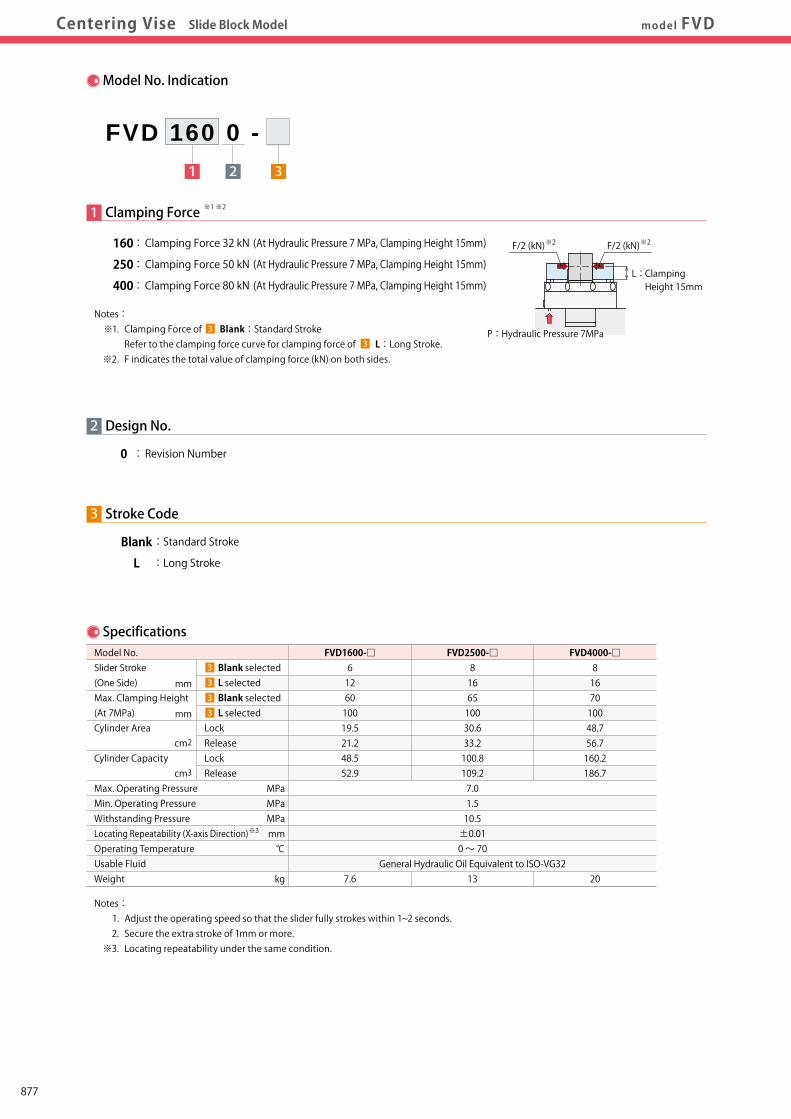
Blank : Standard Stroke
L : Long Stroke
Stroke Code
1 Clamping Force
160 : Clamping Force 32 kN (At Hydraulic Pressure 7 MPa, Clamping Height 15mm)
250 : Clamping Force 50 kN (At Hydraulic Pressure 7 MPa, Clamping Height 15mm)
400 : Clamping Force 80 kN (At Hydraulic Pressure 7 MPa, Clamping Height 15mm)
1 2 3
FVD 160 0 -
Model No. Slider Stroke (One Side) Max. Clamping Height (At 7MPa) Cylinder Area
Cylinder Capacity
Max. Operating Pressure Min. Operating Pressure Withstanding Pressure Locating Repeatability (X-axis Direction) Operating Temperature Usable Fluid Weight
Blank selected L selected Blank selected L selected Lock Release Lock Release
FVD1600-□6126010019.521.248.552.9
7.6
FVD2500-□8166510030.633.2100.8109.27.01.510.5±0.010 ~ 70
General Hydraulic Oil Equivalent to ISO-VG3213
FVD4000-□8167010048.756.7160.2186.7
20
MPaMPaMPamm℃
kg
cm3
cm2
mm
mm
Notes: 1. Adjust the operating speed so that the slider fully strokes within 1~2 seconds. 2. Secure the extra stroke of 1mm or more. ※3. Locating repeatability under the same condition.
Notes: ※1. Clamping Force of Blank:Standard Stroke Refer to the clamping force curve for clamping force of L:Long Stroke. ※2. F indicates the total value of clamping force (kN) on both sides.
※3
※1 ※2
3
3
3
3
3
3
L : Clamping Height 15mm
※2F/2 (kN) ※2F/2 (kN)
P : Hydraulic Pressure 7MPa
877
Work Support
LDLCTNCTC
Swing Clamp
LHA
Pneumatic Series
Hydraulic Series
Valve / CouplerHydraulic Unit
Cautions / Others
High-PowerSeries
Manual OperationAccessories
Hole Clamp
SFASFC
Link Clamp
LKALKCLKWLM/LJTMA-2TMA-1
Block Cylinder
DBADBC
Control Valve
BZLBZTBZX/JZG
Pallet Clamp
VSVT
Expansion Locating Pin
VFLVFMVFJVFK
FPFQ
Pull Stud Clamp
FVAFVDFVC
Centering Vise
DWA/DWB
CustomizedSpring Cylinder
LHCLHSLHWLT/LGTLA-2TLB-2TLA-1
LLW
Air SensingLift Cylinder
Compact Cylinder
LLLLRLLUDPDRDSDT
Introduction ApplicationExamples
ActionDescription Cautions
Model FVAModel No. IndicationSpecifications・External Dimensions
Model FVDModel No. IndicationSpecifications・External Dimensions
Model FVCModel No. IndicationSpecifications・External DimensionsCentering Vise Slide Block Model model FVD
Model No. Indication MEMO
Specifications
2
0 : Revision Number
Design No.
3
Blank : Standard Stroke
L : Long Stroke
Stroke Code
1 Clamping Force
160 : Clamping Force 32 kN (At Hydraulic Pressure 7 MPa, Clamping Height 15mm)
250 : Clamping Force 50 kN (At Hydraulic Pressure 7 MPa, Clamping Height 15mm)
400 : Clamping Force 80 kN (At Hydraulic Pressure 7 MPa, Clamping Height 15mm)
1 2 3
FVD 160 0 -
Model No. Slider Stroke (One Side) Max. Clamping Height (At 7MPa) Cylinder Area
Cylinder Capacity
Max. Operating Pressure Min. Operating Pressure Withstanding Pressure Locating Repeatability (X-axis Direction) Operating Temperature Usable Fluid Weight
Blank selected L selected Blank selected L selected Lock Release Lock Release
FVD1600-□6126010019.521.248.552.9
7.6
FVD2500-□8166510030.633.2100.8109.27.01.510.5±0.010 ~ 70
General Hydraulic Oil Equivalent to ISO-VG3213
FVD4000-□8167010048.756.7160.2186.7
20
MPaMPaMPamm℃
kg
cm3
cm2
mm
mm
Notes: 1. Adjust the operating speed so that the slider fully strokes within 1~2 seconds. 2. Secure the extra stroke of 1mm or more. ※3. Locating repeatability under the same condition.
Notes: ※1. Clamping Force of Blank:Standard Stroke Refer to the clamping force curve for clamping force of L:Long Stroke. ※2. F indicates the total value of clamping force (kN) on both sides.
※3
※1 ※2
3
3
3
3
3
3
L : Clamping Height 15mm
※2F/2 (kN) ※2F/2 (kN)
P : Hydraulic Pressure 7MPa
878
Work Support
LDLCTNCTC
Swing Clamp
LHA
Pneumatic Series
Hydraulic Series
Valve / CouplerHydraulic Unit
Cautions / Others
High-PowerSeries
Manual OperationAccessories
Hole Clamp
SFASFC
Link Clamp
LKALKCLKWLM/LJTMA-2TMA-1
Block Cylinder
DBADBC
Control Valve
BZLBZTBZX/JZG
Pallet Clamp
VSVT
Expansion Locating Pin
VFLVFMVFJVFK
FPFQ
Pull Stud Clamp
FVAFVDFVC
Centering Vise
DWA/DWB
CustomizedSpring Cylinder
LHCLHSLHWLT/LGTLA-2TLB-2TLA-1
LLW
Air SensingLift Cylinder
Compact Cylinder
LLLLRLLUDPDRDSDT
Introduction ApplicationExamples
ActionDescription Cautions
Model FVAModel No. IndicationSpecifications・External Dimensions
Model FVDModel No. IndicationSpecifications・External Dimensions
Model FVCModel No. IndicationSpecifications・External Dimensionsmodel FVDCentering Vise Slide Block Model
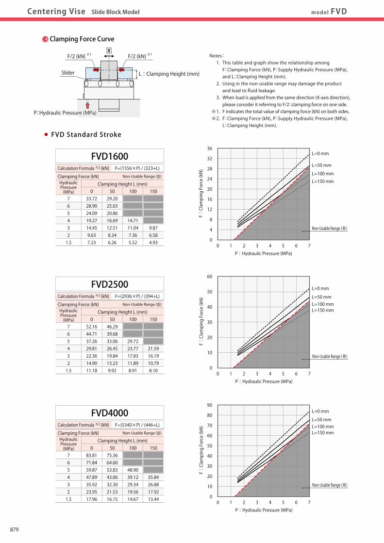
Clamping Force Curve
Notes: 1. This table and graph show the relationship among F:Clamping Force (kN), P:Supply Hydraulic Pressure (MPa), and L:Clamping Height (mm). 2. Using in the non-usable range may damage the product and lead to fluid leakage. 3. When load is applied from the same direction (X-axis direction), please consider it referring to F/2:clamping force on one side. ※1. F indicates the total value of clamping force (kN) on both sides. ※2. F:Clamping Force (kN), P:Supply Hydraulic Pressure (MPa), L:Clamping Height (mm).
L : Clamping Height (mm)
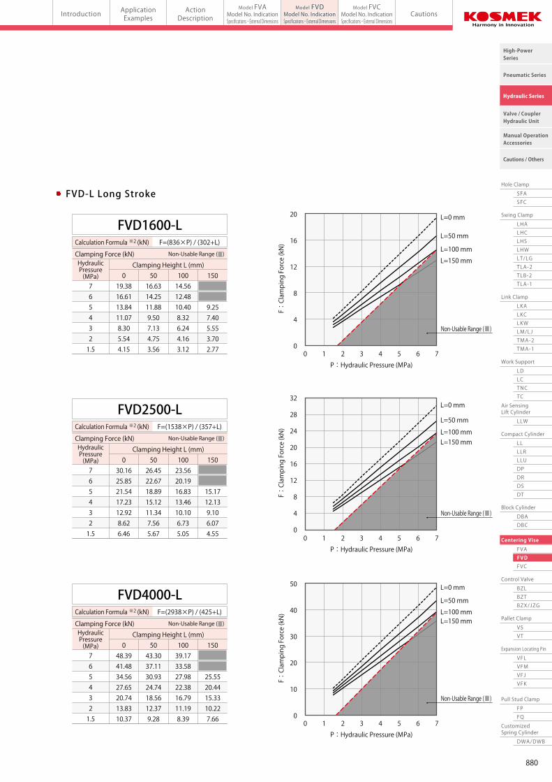
FVD-L Long StrokeFVD Standard Stroke
10 2 3 4 5 6 7
10 2 3 4 5 6 7
10 2 3 4 5 6 7
L=0 mm
L=50 mm
L=100 mm
L=150 mm
L=0 mm
L=50 mmL=100 mmL=150 mm
L=0 mm
L=50 mmL=100 mmL=150 mm
P:Hydraulic Pressure (MPa)
F:Clamping Force (kN)
P:Hydraulic Pressure (MPa)
F:Clamping Force (kN)
7 6 5 4 3 2 1.5
FVD1600Calculation Formula ※2 (kN)
Clamping Height L (mm) Clamping Force (kN) Non-Usable Range (■)
7 6 5 4 3 2 1.5
FVD2500
7 6 5 4 3 2 1.5
FVD4000
Non-Usable Range (■)
Non-Usable Range (■)
HydraulicPressure(MPa)
Calculation Formula ※2 (kN)
Clamping Height L (mm) Clamping Force (kN) Non-Usable Range (■)HydraulicPressure(MPa)
Calculation Formula ※2 (kN)
Clamping Height L (mm) Clamping Force (kN) Non-Usable Range (■)HydraulicPressure(MPa)
P:Hydraulic Pressure (MPa)
F:Clamping Force (kN)
Non-Usable Range (■)
10 2 3 4 5 6 7
10 2 3 4 5 6 7
10 2 3 4 5 6 7
L=0 mm
L=50 mm
L=100 mm
L=150 mm
L=0 mm
L=50 mm
L=100 mmL=150 mm
L=0 mm
L=50 mm
L=100 mmL=150 mm
Non-Usable Range (■)
Non-Usable Range (■)
P:Hydraulic Pressure (MPa)
F:Clamping Force (kN)
P:Hydraulic Pressure (MPa)
F:Clamping Force (kN)
P:Hydraulic Pressure (MPa)
F:Clamping Force (kN)
7 6 5 4 3 2 1.5
FVD1600-L
7 6 5 4 3 2 1.5
FVD2500-L
7 6 5 4 3 2 1.5
FVD4000-L
Non-Usable Range (■)
Calculation Formula ※2 (kN)
Clamping Height L (mm) Clamping Force (kN) Non-Usable Range (■)HydraulicPressure(MPa)
Calculation Formula ※2 (kN)
Clamping Height L (mm) Clamping Force (kN) Non-Usable Range (■)HydraulicPressure(MPa)
Calculation Formula ※2 (kN)
Clamping Height L (mm) Clamping Force (kN) Non-Usable Range (■)HydraulicPressure(MPa)
0
4
8
12
16
20
24
28
32
36
0
10
20
30
40
50
60
0
10
20
30
40
50
60
70
80
90
0
4
8
12
16
20
0
4
8
12
16
20
24
28
32
0
10
20
30
40
50
F=(1556×P) / (323+L)
033.7228.9024.0919.2714.459.637.23
5029.2025.0320.8616.6912.518.346.26
100
14.7111.047.365.52
F=(2936×P) / (394+L)
052.1644.7137.2629.8122.3614.9011.18
5046.2939.6833.0626.4519.8413.239.92
100
29.7223.7717.8311.898.91
150
21.5916.1910.798.10
F=(5340×P) / (446+L)
083.8171.8459.8747.8935.9223.9517.96
5075.3664.6053.8343.0632.3021.5316.15
100
48.9039.1229.3419.5614.67
150
35.8426.8817.9213.44
150
9.876.584.93
F=(836×P) / (302+L)
019.3816.6113.8411.078.305.544.15
5016.6314.2511.889.507.134.753.56
10014.5612.4810.408.326.244.163.12
F=(1538×P) / (357+L)
030.1625.8521.5417.2312.928.626.46
5026.4522.6718.8915.1211.347.565.67
10023.5620.1916.8313.4610.106.735.05
150
15.1712.139.106.074.55
F=(2938×P) / (425+L)
048.3941.4834.5627.6520.7413.8310.37
5043.3037.1130.9324.7418.5612.379.28
10039.1733.5827.9822.3816.7911.198.39
150
25.5520.4415.3310.227.66
150
9.257.405.553.702.77
P:Hydraulic Pressure (MPa)P:Hydraulic Pressure (MPa)
※1F/2 (kN)
Slider
※1F/2 (kN)X
879
Work Support
LDLCTNCTC
Swing Clamp
LHA
Pneumatic Series
Hydraulic Series
Valve / CouplerHydraulic Unit
Cautions / Others
High-PowerSeries
Manual OperationAccessories
Hole Clamp
SFASFC
Link Clamp
LKALKCLKWLM/LJTMA-2TMA-1
Block Cylinder
DBADBC
Control Valve
BZLBZTBZX/JZG
Pallet Clamp
VSVT
Expansion Locating Pin
VFLVFMVFJVFK
FPFQ
Pull Stud Clamp
FVAFVDFVC
Centering Vise
DWA/DWB
CustomizedSpring Cylinder
LHCLHSLHWLT/LGTLA-2TLB-2TLA-1
LLW
Air SensingLift Cylinder
Compact Cylinder
LLLLRLLUDPDRDSDT
Introduction ApplicationExamples
ActionDescription Cautions
Model FVAModel No. IndicationSpecifications・External Dimensions
Model FVDModel No. IndicationSpecifications・External Dimensions
Model FVCModel No. IndicationSpecifications・External Dimensionsmodel FVDCentering Vise Slide Block Model
Clamping Force Curve
Notes: 1. This table and graph show the relationship among F:Clamping Force (kN), P:Supply Hydraulic Pressure (MPa), and L:Clamping Height (mm). 2. Using in the non-usable range may damage the product and lead to fluid leakage. 3. When load is applied from the same direction (X-axis direction), please consider it referring to F/2:clamping force on one side. ※1. F indicates the total value of clamping force (kN) on both sides. ※2. F:Clamping Force (kN), P:Supply Hydraulic Pressure (MPa), L:Clamping Height (mm).
L : Clamping Height (mm)
FVD-L Long StrokeFVD Standard Stroke
10 2 3 4 5 6 7
10 2 3 4 5 6 7
10 2 3 4 5 6 7
L=0 mm
L=50 mm
L=100 mm
L=150 mm
L=0 mm
L=50 mmL=100 mmL=150 mm
L=0 mm
L=50 mmL=100 mmL=150 mm
P:Hydraulic Pressure (MPa)
F:Clamping Force (kN)
P:Hydraulic Pressure (MPa)
F:Clamping Force (kN)
7 6 5 4 3 2 1.5
FVD1600Calculation Formula ※2 (kN)
Clamping Height L (mm) Clamping Force (kN) Non-Usable Range (■)
7 6 5 4 3 2 1.5
FVD2500
7 6 5 4 3 2 1.5
FVD4000
Non-Usable Range (■)
Non-Usable Range (■)
HydraulicPressure(MPa)
Calculation Formula ※2 (kN)
Clamping Height L (mm) Clamping Force (kN) Non-Usable Range (■)HydraulicPressure(MPa)
Calculation Formula ※2 (kN)
Clamping Height L (mm) Clamping Force (kN) Non-Usable Range (■)HydraulicPressure(MPa)
P:Hydraulic Pressure (MPa)
F:Clamping Force (kN)
Non-Usable Range (■)
10 2 3 4 5 6 7
10 2 3 4 5 6 7
10 2 3 4 5 6 7
L=0 mm
L=50 mm
L=100 mm
L=150 mm
L=0 mm
L=50 mm
L=100 mmL=150 mm
L=0 mm
L=50 mm
L=100 mmL=150 mm
Non-Usable Range (■)
Non-Usable Range (■)
P:Hydraulic Pressure (MPa)
F:Clamping Force (kN)
P:Hydraulic Pressure (MPa)
F:Clamping Force (kN)
P:Hydraulic Pressure (MPa)
F:Clamping Force (kN)
7 6 5 4 3 2 1.5
FVD1600-L
7 6 5 4 3 2 1.5
FVD2500-L
7 6 5 4 3 2 1.5
FVD4000-L
Non-Usable Range (■)
Calculation Formula ※2 (kN)
Clamping Height L (mm) Clamping Force (kN) Non-Usable Range (■)HydraulicPressure(MPa)
Calculation Formula ※2 (kN)
Clamping Height L (mm) Clamping Force (kN) Non-Usable Range (■)HydraulicPressure(MPa)
Calculation Formula ※2 (kN)
Clamping Height L (mm) Clamping Force (kN) Non-Usable Range (■)HydraulicPressure(MPa)
0
4
8
12
16
20
24
28
32
36
0
10
20
30
40
50
60
0
10
20
30
40
50
60
70
80
90
0
4
8
12
16
20
0
4
8
12
16
20
24
28
32
0
10
20
30
40
50
F=(1556×P) / (323+L)
033.7228.9024.0919.2714.459.637.23
5029.2025.0320.8616.6912.518.346.26
100
14.7111.047.365.52
F=(2936×P) / (394+L)
052.1644.7137.2629.8122.3614.9011.18
5046.2939.6833.0626.4519.8413.239.92
100
29.7223.7717.8311.898.91
150
21.5916.1910.798.10
F=(5340×P) / (446+L)
083.8171.8459.8747.8935.9223.9517.96
5075.3664.6053.8343.0632.3021.5316.15
100
48.9039.1229.3419.5614.67
150
35.8426.8817.9213.44
150
9.876.584.93
F=(836×P) / (302+L)
019.3816.6113.8411.078.305.544.15
5016.6314.2511.889.507.134.753.56
10014.5612.4810.408.326.244.163.12
F=(1538×P) / (357+L)
030.1625.8521.5417.2312.928.626.46
5026.4522.6718.8915.1211.347.565.67
10023.5620.1916.8313.4610.106.735.05
150
15.1712.139.106.074.55
F=(2938×P) / (425+L)
048.3941.4834.5627.6520.7413.8310.37
5043.3037.1130.9324.7418.5612.379.28
10039.1733.5827.9822.3816.7911.198.39
150
25.5520.4415.3310.227.66
150
9.257.405.553.702.77
P:Hydraulic Pressure (MPa)P:Hydraulic Pressure (MPa)
※1F/2 (kN)
Slider
※1F/2 (kN)X
880
Work Support
LDLCTNCTC
Swing Clamp
LHA
Pneumatic Series
Hydraulic Series
Valve / CouplerHydraulic Unit
Cautions / Others
High-PowerSeries
Manual OperationAccessories
Hole Clamp
SFASFC
Link Clamp
LKALKCLKWLM/LJTMA-2TMA-1
Block Cylinder
DBADBC
Control Valve
BZLBZTBZX/JZG
Pallet Clamp
VSVT
Expansion Locating Pin
VFLVFMVFJVFK
FPFQ
Pull Stud Clamp
FVAFVDFVC
Centering Vise
DWA/DWB
CustomizedSpring Cylinder
LHCLHSLHWLT/LGTLA-2TLB-2TLA-1
LLW
Air SensingLift Cylinder
Compact Cylinder
LLLLRLLUDPDRDSDT
Introduction ApplicationExamples
ActionDescription Cautions
Model FVAModel No. IndicationSpecifications・External Dimensions
Model FVDModel No. IndicationSpecifications・External Dimensions
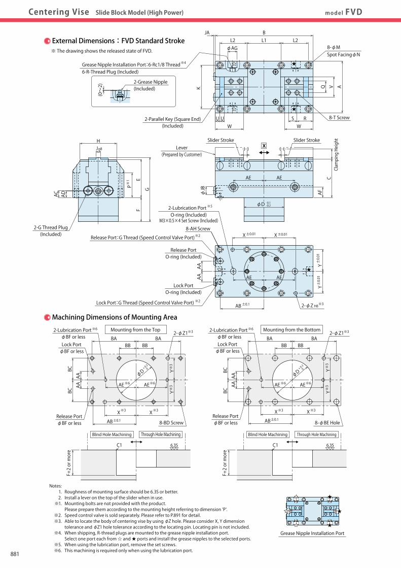
Model FVCModel No. IndicationSpecifications・External Dimensionsmodel FVDCentering Vise Slide Block Model (High Power)
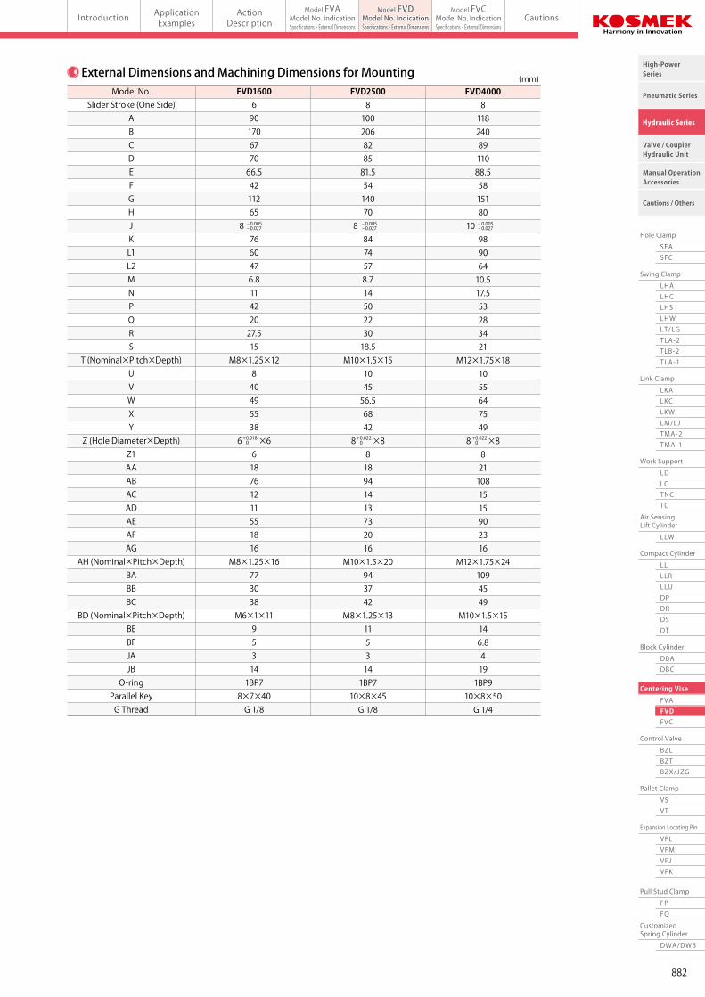
External Dimensions and Machining Dimensions for Mounting (mm)Model No.
Slider Stroke (One Side)ABCDEFGHJKL1L2MNPQRS
T (Nominal×Pitch×Depth)UVWXY
Z (Hole Diameter×Depth)Z1AAABACADAEAFAG
AH (Nominal×Pitch×Depth)BABBBC
BD (Nominal×Pitch×Depth)BEBFJAJBO-ring
Parallel KeyG Thread
FVD1600690170677066.54211265
8 7660476.811422027.515
M8×1.25×12840495538
6 ×6618761211551816
M8×1.25×16773038
M6×1×11953141BP78×7×40G 1/8
FVD25008100206828581.55414070
8 8474578.71450223018.5
M10×1.5×15104556.56842
8 ×8818941413732016
M10×1.5×20943742
M8×1.25×131153141BP7
10×8×45G 1/8
FVD400081182408911088.55815180
10 98906410.517.553283421
M12×1.75×181055647549
8 ×88211081515902316
M12×1.75×241094549
M10×1.5×15146.84191BP9
10×8×50G 1/4
- 0.005- 0.027
- 0.005- 0.027
- 0.005- 0.027
+ 0.018 0
+ 0.022 0
+ 0.022 0
External Dimensions:FVD Standard Stroke※ The drawing shows the released state of FVD.
AVQ
BL2
φAGL1 L2
JA
K
WWRSU U
X
※1
HJg8
AE AE
AC AFAD
φD -0.1-0.2
φJB
C
G
FE
P
※3
AAAA
AB±0.1
X±0.01 X±0.01
Y±0.01
Y±0.01
2-φZ H8
Notes: 1. Roughness of mounting surface should be 6.3S or better. 2. Install a lever on the top of the slider when in use. ※1. Mounting bolts are not provided with the product. Please prepare them according to the mounting height referring to dimension 'P'. ※2. Speed control valve is sold separately. Please refer to P.891 for detail. ※3. Able to locate the body of centering vise by using φZ hole. Please consider X, Y dimension tolerance and φZ1 hole tolerance according to the locating pin. Locating pin is not included. ※4. When shipping, R-thread plugs are mounted to the grease nipple installation port. Select one port each from ☆ and ★ ports and install the grease nipples to the selected ports. ※5. When using the lubrication port, remove the set screws. ※6. This machining is required only when using the lubrication port.
Grease Nipple Installation Port
※4Grease Nipple Installation Port:6-Rc1/8 Thread
2-Grease Nipple(Included)
6-R-Thread Plug (Included)
(0~2)
※3
※3 ※3
※3
※3
BA BABB BB
AB±0.1X X
BCBC
AAAA
YY
Lock PortφBF or less
Release PortφBF or less
BABB BB
BA
AB±0.1X X
AAAA
BCBC Y
Y
φD+ 0.3
0
φD+ 0.3
0
Lock PortφBF or less
Release PortφBF or less
2-φZ1※3
※3 ※3
※3
※3
2-φZ1
8-φBE Hole8-BD Screw
Machining Dimensions of Mounting Area
6.3S
F+2 or more
C1
Blind Hole Machining Through Hole Machining
6.3S
F+2 or more
C1
Mounting from the Top Mounting from the Bottom
Blind Hole Machining Through Hole Machining
※6
※6 ※6
2-Lubrication Port φBF or less
AE AE※6 ※6AE AE
AE AE
※52-Lubrication PortO-ring (Included)
M3×0.5×4 Set Screw (Included)
※62-Lubrication Port φBF or less
Lever(Prepared by Customer)
Clamping Height
2-Parallel Key (Square End)(Included)
8-T Screw
Slider Stroke Slider Stroke
※2
※2
Release PortO-ring (Included)
Lock PortO-ring (Included)
8-AH Screw
Release Port:G Thread (Speed Control Valve Port)
Lock Port:G Thread (Speed Control Valve Port)
8-φMSpot FacingφN
2-G Thread Plug(Included)
881
Work Support
LDLCTNCTC
Swing Clamp
LHA
Pneumatic Series
Hydraulic Series
Valve / CouplerHydraulic Unit
Cautions / Others
High-PowerSeries
Manual OperationAccessories
Hole Clamp
SFASFC
Link Clamp
LKALKCLKWLM/LJTMA-2TMA-1
Block Cylinder
DBADBC
Control Valve
BZLBZTBZX/JZG
Pallet Clamp
VSVT
Expansion Locating Pin
VFLVFMVFJVFK
FPFQ
Pull Stud Clamp
FVAFVDFVC
Centering Vise
DWA/DWB
CustomizedSpring Cylinder
LHCLHSLHWLT/LGTLA-2TLB-2TLA-1
LLW
Air SensingLift Cylinder
Compact Cylinder
LLLLRLLUDPDRDSDT
Introduction ApplicationExamples
ActionDescription Cautions
Model FVAModel No. IndicationSpecifications・External Dimensions
Model FVDModel No. IndicationSpecifications・External Dimensions
Model FVCModel No. IndicationSpecifications・External Dimensionsmodel FVDCentering Vise Slide Block Model (High Power)
External Dimensions and Machining Dimensions for Mounting (mm)Model No.
Slider Stroke (One Side)ABCDEFGHJKL1L2MNPQRS
T (Nominal×Pitch×Depth)UVWXY
Z (Hole Diameter×Depth)Z1AAABACADAEAFAG
AH (Nominal×Pitch×Depth)BABBBC
BD (Nominal×Pitch×Depth)BEBFJAJBO-ring
Parallel KeyG Thread
FVD1600690170677066.54211265
8 7660476.811422027.515
M8×1.25×12840495538
6 ×6618761211551816
M8×1.25×16773038
M6×1×11953141BP78×7×40G 1/8
FVD25008100206828581.55414070
8 8474578.71450223018.5
M10×1.5×15104556.56842
8 ×8818941413732016
M10×1.5×20943742
M8×1.25×131153141BP7
10×8×45G 1/8
FVD400081182408911088.55815180
10 98906410.517.553283421
M12×1.75×181055647549
8 ×88211081515902316
M12×1.75×241094549
M10×1.5×15146.84191BP9
10×8×50G 1/4
- 0.005- 0.027
- 0.005- 0.027
- 0.005- 0.027
+ 0.018 0
+ 0.022 0
+ 0.022 0
External Dimensions:FVD Standard Stroke※ The drawing shows the released state of FVD.
AVQ
BL2
φAGL1 L2
JA
K
WWRSU U
X
※1
HJg8
AE AE
AC AFAD
φD -0.1-0.2
φJB
C
G
FE
P
※3
AAAA
AB±0.1
X±0.01 X±0.01
Y±0.01
Y±0.01
2-φZ H8
Notes: 1. Roughness of mounting surface should be 6.3S or better. 2. Install a lever on the top of the slider when in use. ※1. Mounting bolts are not provided with the product. Please prepare them according to the mounting height referring to dimension 'P'. ※2. Speed control valve is sold separately. Please refer to P.891 for detail. ※3. Able to locate the body of centering vise by using φZ hole. Please consider X, Y dimension tolerance and φZ1 hole tolerance according to the locating pin. Locating pin is not included. ※4. When shipping, R-thread plugs are mounted to the grease nipple installation port. Select one port each from ☆ and ★ ports and install the grease nipples to the selected ports. ※5. When using the lubrication port, remove the set screws. ※6. This machining is required only when using the lubrication port.
Grease Nipple Installation Port
※4Grease Nipple Installation Port:6-Rc1/8 Thread
2-Grease Nipple(Included)
6-R-Thread Plug (Included)
(0~2)
※3
※3 ※3
※3
※3
BA BABB BB
AB±0.1X X
BCBC
AAAA
YY
Lock PortφBF or less
Release PortφBF or less
BABB BB
BA
AB±0.1X X
AAAA
BCBC Y
Y
φD+ 0.3
0
φD+ 0.3
0
Lock PortφBF or less
Release PortφBF or less
2-φZ1※3
※3 ※3
※3
※3
2-φZ1
8-φBE Hole8-BD Screw
Machining Dimensions of Mounting Area
6.3S
F+2 or more
C1
Blind Hole Machining Through Hole Machining
6.3S
F+2 or more
C1
Mounting from the Top Mounting from the Bottom
Blind Hole Machining Through Hole Machining
※6
※6 ※6
2-Lubrication Port φBF or less
AE AE※6 ※6AE AE
AE AE
※52-Lubrication PortO-ring (Included)
M3×0.5×4 Set Screw (Included)
※62-Lubrication Port φBF or less
Lever(Prepared by Customer)
Clamping Height
2-Parallel Key (Square End)(Included)
8-T Screw
Slider Stroke Slider Stroke
※2
※2
Release PortO-ring (Included)
Lock PortO-ring (Included)
8-AH Screw
Release Port:G Thread (Speed Control Valve Port)
Lock Port:G Thread (Speed Control Valve Port)
8-φMSpot FacingφN
2-G Thread Plug(Included)
882
Work Support
LDLCTNCTC
Swing Clamp
LHA
Pneumatic Series
Hydraulic Series
Valve / CouplerHydraulic Unit
Cautions / Others
High-PowerSeries
Manual OperationAccessories
Hole Clamp
SFASFC
Link Clamp
LKALKCLKWLM/LJTMA-2TMA-1
Block Cylinder
DBADBC
Control Valve
BZLBZTBZX/JZG
Pallet Clamp
VSVT
Expansion Locating Pin
VFLVFMVFJVFK
FPFQ
Pull Stud Clamp
FVAFVDFVC
Centering Vise
DWA/DWB
CustomizedSpring Cylinder
LHCLHSLHWLT/LGTLA-2TLB-2TLA-1
LLW
Air SensingLift Cylinder
Compact Cylinder
LLLLRLLUDPDRDSDT
Introduction ApplicationExamples
ActionDescription Cautions
Model FVAModel No. IndicationSpecifications・External Dimensions
Model FVDModel No. IndicationSpecifications・External Dimensions
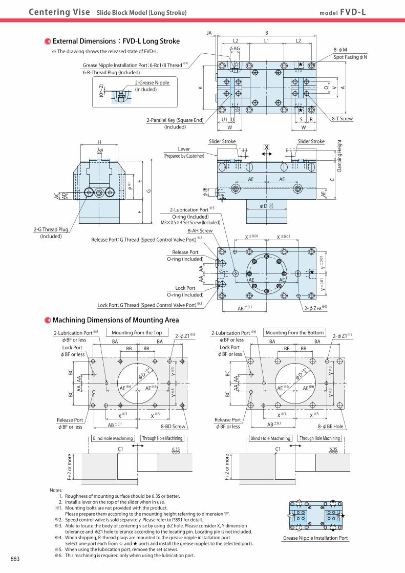
Model FVCModel No. IndicationSpecifications・External Dimensionsmodel FVD-LCentering Vise Slide Block Model (Long Stroke)
※62-Lubrication Port φBF or less
※62-Lubrication Port φBF or less
※6 ※6AE AE
External Dimensions:FVD-L Long Stroke※ The drawing shows the released state of FVD-L.
※3
※3 ※3
※3
※3
BA BABB BB
AB±0.1X X
BCBC
AAAA
YY
Lock PortφBF or less
Release PortφBF or less
BABB BB
BA
AB±0.1X X
AAAA
BCBC Y
Y
φD+ 0.3
0
φD+ 0.3
0
Lock PortφBF or less
Release PortφBF or less
2-φZ1※3
※3 ※3
※3
※3
2-φZ1
8-φBE Hole8-BD Screw
Machining Dimensions of Mounting Area
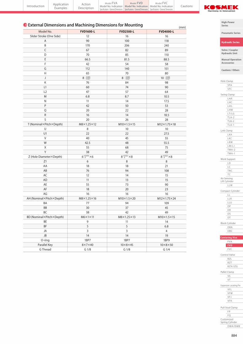
External Dimensions and Machining Dimensions for Mounting
6.3S
F+2 or more
C1
Through Hole Machining
6.3S
F+2 or more
C1
Mounting from the Top Mounting from the Bottom
Through Hole Machining
Model No.Slider Stroke (One Side)
ABCDEFGHJKL1L2MNPQRS
T (Nominal×Pitch×Depth)UU1VWXY
Z (Hole Diameter×Depth)Z1AAABACADAEAFAG
AH (Nominal×Pitch×Depth)BABBBC
BD (Nominal×Pitch×Depth)BEBFJAJBO-ring
Parallel KeyG Thread
FVD1600-L1290170677066.54211265
8 7660476.81142201620
M8×1.25×128224042.55538
6 ×6618761211551816
M8×1.25×16773038
M6×1×11953141BP78×7×40G 1/8
FVD2500-L16100206828581.55414070
8 8474578.71450221426
M10×1.5×15102245486842
8 ×8818941413732016
M10×1.5×20943742
M8×1.25×131153141BP7
10×8×45G 1/8
FVD4000-L161182408911088.55815180
10 98906410.517.5532818.528
M12×1.75×181027.55555.57549
8 ×88211081515902316
M12×1.75×241094549
M10×1.5×15146.84191BP9
10×8×50G 1/4
(mm)
- 0.005- 0.027
- 0.005- 0.027
- 0.005- 0.027
+ 0.018 0
+ 0.022 0
+ 0.022 0
AVQ
BL2 L1 L2
JA
K
WWRSU1 U
※4Grease Nipple Installation Port:6-Rc1/8 Thread
2-Grease Nipple(Included)
6-R-Thread Plug (Included)
(0~2)
φAG
X
φD -0.1-0.2
φJB
CAE AE
AF
※1
HJg8
AC AD
G
FE
P
※3
AAAA
AB±0.1
X±0.01 X±0.01
Y±0.01
Y±0.01
2-φZ H8
Notes: 1. Roughness of mounting surface should be 6.3S or better. 2. Install a lever on the top of the slider when in use. ※1. Mounting bolts are not provided with the product. Please prepare them according to the mounting height referring to dimension 'P'. ※2. Speed control valve is sold separately. Please refer to P.891 for detail. ※3. Able to locate the body of centering vise by using φZ hole. Please consider X, Y dimension tolerance and φZ1 hole tolerance according to the locating pin. Locating pin is not included. ※4. When shipping, R-thread plugs are mounted to the grease nipple installation port. Select one port each from ☆ and ★ ports and install the grease nipples to the selected ports. ※5. When using the lubrication port, remove the set screws. ※6. This machining is required only when using the lubrication port.
Grease Nipple Installation Port
AE AE
※6 ※6AE AE
※52-Lubrication PortO-ring (Included)
M3×0.5×4 Set Screw (Included)
Blind Hole Machining Blind Hole Machining
8-φMSpot FacingφN
Lever(Prepared by Customer)
Clamping HeightSlider Stroke Slider Stroke
2-G Thread Plug(Included)
8-AH Screw
Release PortO-ring (Included)
Lock PortO-ring (Included)
2-Parallel Key (Square End)(Included)
8-T Screw
※2
※2
Release Port:G Thread (Speed Control Valve Port)
Lock Port:G Thread (Speed Control Valve Port)
883
Work Support
LDLCTNCTC
Swing Clamp
LHA
Pneumatic Series
Hydraulic Series
Valve / CouplerHydraulic Unit
Cautions / Others
High-PowerSeries
Manual OperationAccessories
Hole Clamp
SFASFC
Link Clamp
LKALKCLKWLM/LJTMA-2TMA-1
Block Cylinder
DBADBC
Control Valve
BZLBZTBZX/JZG
Pallet Clamp
VSVT
Expansion Locating Pin
VFLVFMVFJVFK
FPFQ
Pull Stud Clamp
FVAFVDFVC
Centering Vise
DWA/DWB
CustomizedSpring Cylinder
LHCLHSLHWLT/LGTLA-2TLB-2TLA-1
LLW
Air SensingLift Cylinder
Compact Cylinder
LLLLRLLUDPDRDSDT
Introduction ApplicationExamples
ActionDescription Cautions
Model FVAModel No. IndicationSpecifications・External Dimensions
Model FVDModel No. IndicationSpecifications・External Dimensions
Model FVCModel No. IndicationSpecifications・External Dimensionsmodel FVD-LCentering Vise Slide Block Model (Long Stroke)
※62-Lubrication Port φBF or less
※62-Lubrication Port φBF or less
※6 ※6AE AE
External Dimensions:FVD-L Long Stroke※ The drawing shows the released state of FVD-L.
※3
※3 ※3
※3
※3
BA BABB BB
AB±0.1X X
BCBC
AAAA
YY
Lock PortφBF or less
Release PortφBF or less
BABB BB
BA
AB±0.1X X
AAAA
BCBC Y
Y
φD+ 0.3
0
φD+ 0.3
0
Lock PortφBF or less
Release PortφBF or less
2-φZ1※3
※3 ※3
※3
※3
2-φZ1
8-φBE Hole8-BD Screw
Machining Dimensions of Mounting Area
External Dimensions and Machining Dimensions for Mounting
6.3S
F+2 or more
C1
Through Hole Machining
6.3S
F+2 or more
C1
Mounting from the Top Mounting from the Bottom
Through Hole Machining
Model No.Slider Stroke (One Side)
ABCDEFGHJKL1L2MNPQRS
T (Nominal×Pitch×Depth)UU1VWXY
Z (Hole Diameter×Depth)Z1AAABACADAEAFAG
AH (Nominal×Pitch×Depth)BABBBC
BD (Nominal×Pitch×Depth)BEBFJAJBO-ring
Parallel KeyG Thread
FVD1600-L1290170677066.54211265
8 7660476.81142201620
M8×1.25×128224042.55538
6 ×6618761211551816
M8×1.25×16773038
M6×1×11953141BP78×7×40G 1/8
FVD2500-L16100206828581.55414070
8 8474578.71450221426
M10×1.5×15102245486842
8 ×8818941413732016
M10×1.5×20943742
M8×1.25×131153141BP7
10×8×45G 1/8
FVD4000-L161182408911088.55815180
10 98906410.517.5532818.528
M12×1.75×181027.55555.57549
8 ×88211081515902316
M12×1.75×241094549
M10×1.5×15146.84191BP9
10×8×50G 1/4
(mm)
- 0.005- 0.027
- 0.005- 0.027
- 0.005- 0.027
+ 0.018 0
+ 0.022 0
+ 0.022 0
AVQ
BL2 L1 L2
JA
K
WWRSU1 U
※4Grease Nipple Installation Port:6-Rc1/8 Thread
2-Grease Nipple(Included)
6-R-Thread Plug (Included)
(0~2)
φAG
X
φD -0.1-0.2
φJB
CAE AE
AF
※1
HJg8
AC AD
G
FE
P
※3
AAAA
AB±0.1
X±0.01 X±0.01
Y±0.01
Y±0.01
2-φZ H8
Notes: 1. Roughness of mounting surface should be 6.3S or better. 2. Install a lever on the top of the slider when in use. ※1. Mounting bolts are not provided with the product. Please prepare them according to the mounting height referring to dimension 'P'. ※2. Speed control valve is sold separately. Please refer to P.891 for detail. ※3. Able to locate the body of centering vise by using φZ hole. Please consider X, Y dimension tolerance and φZ1 hole tolerance according to the locating pin. Locating pin is not included. ※4. When shipping, R-thread plugs are mounted to the grease nipple installation port. Select one port each from ☆ and ★ ports and install the grease nipples to the selected ports. ※5. When using the lubrication port, remove the set screws. ※6. This machining is required only when using the lubrication port.
Grease Nipple Installation Port
AE AE
※6 ※6AE AE
※52-Lubrication PortO-ring (Included)
M3×0.5×4 Set Screw (Included)
Blind Hole Machining Blind Hole Machining
8-φMSpot FacingφN
Lever(Prepared by Customer)
Clamping HeightSlider Stroke Slider Stroke
2-G Thread Plug(Included)
8-AH Screw
Release PortO-ring (Included)
Lock PortO-ring (Included)
2-Parallel Key (Square End)(Included)
8-T Screw
※2
※2
Release Port:G Thread (Speed Control Valve Port)
Lock Port:G Thread (Speed Control Valve Port)
884
Work Support
LDLCTNCTC
Swing Clamp
LHA
Pneumatic Series
Hydraulic Series
Valve / CouplerHydraulic Unit
Cautions / Others
High-PowerSeries
Manual OperationAccessories
Hole Clamp
SFASFC
Link Clamp
LKALKCLKWLM/LJTMA-2TMA-1
Block Cylinder
DBADBC
Control Valve
BZLBZTBZX/JZG
Pallet Clamp
VSVT
Expansion Locating Pin
VFLVFMVFJVFK
FPFQ
Pull Stud Clamp
FVAFVDFVC
Centering Vise
DWA/DWB
CustomizedSpring Cylinder
LHCLHSLHWLT/LGTLA-2TLB-2TLA-1
LLW
Air SensingLift Cylinder
Compact Cylinder
LLLLRLLUDPDRDSDT
Introduction ApplicationExamples
ActionDescription Cautions
Model FVAModel No. IndicationSpecifications・External Dimensions
Model FVDModel No. IndicationSpecifications・External Dimensions
Model FVCModel No. IndicationSpecifications・External Dimensionsmodel FVCCentering Vise Link Motion Model (Long Stroke)
Model No. Indication
Specifications
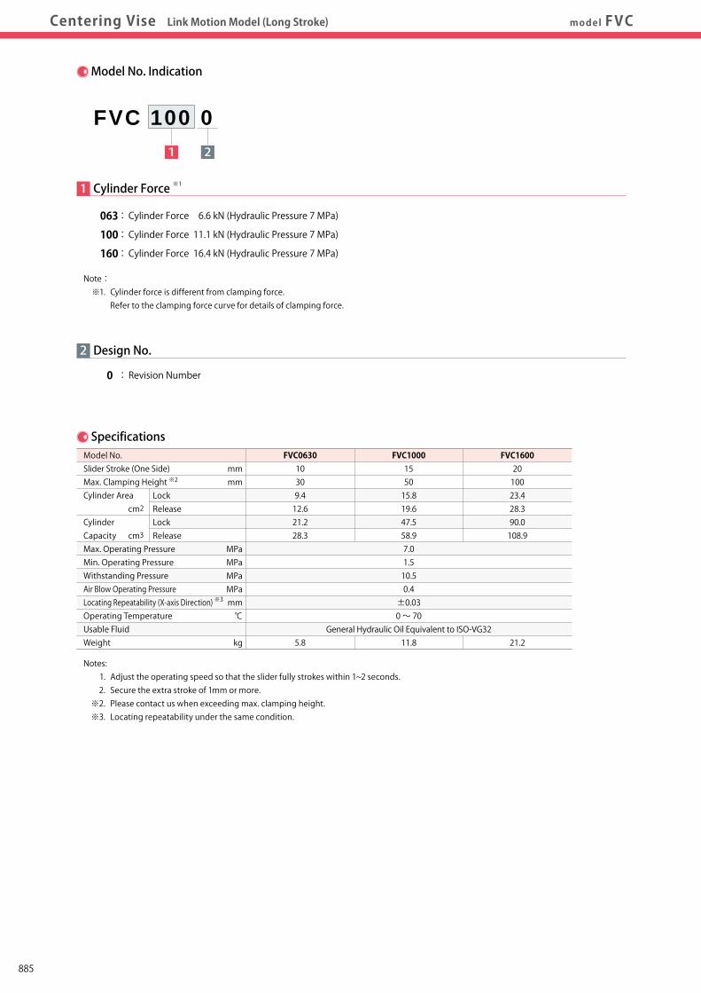
2
0 : Revision Number
Design No.
1 Cylinder Force
063 : Cylinder Force 6.6 kN (Hydraulic Pressure 7 MPa)
100 : Cylinder Force 11.1 kN (Hydraulic Pressure 7 MPa)
160 : Cylinder Force 16.4 kN (Hydraulic Pressure 7 MPa)
1 2
FVC 100 0
Model No. Slider Stroke (One Side) Max. Clamping Height Cylinder Area cm2
Cylinder Capacity cm3
Max. Operating Pressure Min. Operating Pressure Withstanding Pressure Air Blow Operating Pressure Locating Repeatability (X-axis Direction) Operating Temperature Usable Fluid Weight
FVC063010309.412.621.228.3
5.8
FVC1000155015.819.647.558.97.01.510.50.4±0.030 ~ 70
General Hydraulic Oil Equivalent to ISO-VG3211.8
FVC16002010023.428.390.0108.9
21.2
LockReleaseLockRelease
mmmm
MPaMPaMPaMPamm℃
kg
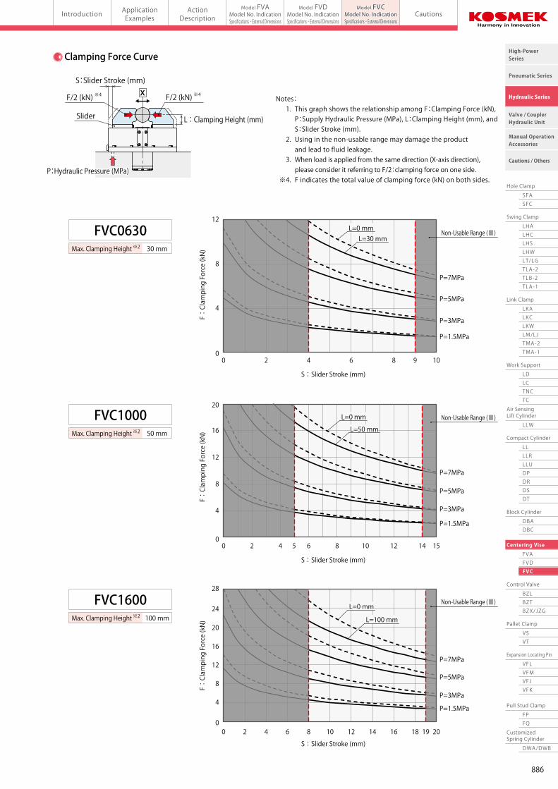
Clamping Force Curve
Notes: 1. This graph shows the relationship among F:Clamping Force (kN), P:Supply Hydraulic Pressure (MPa), L:Clamping Height (mm), and S:Slider Stroke (mm). 2. Using in the non-usable range may damage the product and lead to fluid leakage. 3. When load is applied from the same direction (X-axis direction), please consider it referring to F/2:clamping force on one side. ※4. F indicates the total value of clamping force (kN) on both sides.
※2
Notes: 1. Adjust the operating speed so that the slider fully strokes within 1~2 seconds. 2. Secure the extra stroke of 1mm or more. ※2. Please contact us when exceeding max. clamping height. ※3. Locating repeatability under the same condition.
※3
※1
Note: ※1. Cylinder force is different from clamping force. Refer to the clamping force curve for details of clamping force.
FVC0630
FVC1600
FVC1000
0
4
8
12
0 2 94 6 8 10
S:Slider Stroke (mm)
F:Clamping Force (kN)
P=1.5MPa
P=3MPa
P=5MPa
P=7MPa
L=0 mmL=30 mm
0
4
8
12
16
20
0 2 4 5 6 8 10 12 14 15
S:Slider Stroke (mm)
F:Clamping Force (kN)
P=1.5MPa
P=3MPa
P=5MPa
P=7MPa
L=0 mm
L=50 mm
0
4
8
12
16
28
20
24
0 2 4 6 8 10 12 14 16 18 19 20
S:Slider Stroke (mm)
F:Clamping Force (kN)
P=1.5MPa
P=3MPa
P=5MPa
P=7MPa
L=0 mm
L=100 mm
Non-Usable Range (■)
30 mmMax. Clamping Height※2
50 mmMax. Clamping Height※2
100 mmMax. Clamping Height※2
Non-Usable Range (■)
Non-Usable Range (■)
S:Slider Stroke (mm)
※4F/2 (kN) ※4F/2 (kN)
Slider
X
P:Hydraulic Pressure (MPa)P:Hydraulic Pressure (MPa)
L : Clamping Height (mm)
885
Work Support
LDLCTNCTC
Swing Clamp
LHA
Pneumatic Series
Hydraulic Series
Valve / CouplerHydraulic Unit
Cautions / Others
High-PowerSeries
Manual OperationAccessories
Hole Clamp
SFASFC
Link Clamp
LKALKCLKWLM/LJTMA-2TMA-1
Block Cylinder
DBADBC
Control Valve
BZLBZTBZX/JZG
Pallet Clamp
VSVT
Expansion Locating Pin
VFLVFMVFJVFK
FPFQ
Pull Stud Clamp
FVAFVDFVC
Centering Vise
DWA/DWB
CustomizedSpring Cylinder
LHCLHSLHWLT/LGTLA-2TLB-2TLA-1
LLW
Air SensingLift Cylinder
Compact Cylinder
LLLLRLLUDPDRDSDT
Introduction ApplicationExamples
ActionDescription Cautions
Model FVAModel No. IndicationSpecifications・External Dimensions
Model FVDModel No. IndicationSpecifications・External Dimensions
Model FVCModel No. IndicationSpecifications・External Dimensionsmodel FVCCentering Vise Link Motion Model (Long Stroke)
Model No. Indication
Specifications
2
0 : Revision Number
Design No.
1 Cylinder Force
063 : Cylinder Force 6.6 kN (Hydraulic Pressure 7 MPa)
100 : Cylinder Force 11.1 kN (Hydraulic Pressure 7 MPa)
160 : Cylinder Force 16.4 kN (Hydraulic Pressure 7 MPa)
1 2
FVC 100 0
Model No. Slider Stroke (One Side) Max. Clamping Height Cylinder Area cm2
Cylinder Capacity cm3
Max. Operating Pressure Min. Operating Pressure Withstanding Pressure Air Blow Operating Pressure Locating Repeatability (X-axis Direction) Operating Temperature Usable Fluid Weight
FVC063010309.412.621.228.3
5.8
FVC1000155015.819.647.558.97.01.510.50.4±0.030 ~ 70
General Hydraulic Oil Equivalent to ISO-VG3211.8
FVC16002010023.428.390.0108.9
21.2
LockReleaseLockRelease
mmmm
MPaMPaMPaMPamm℃
kg
Clamping Force Curve
Notes: 1. This graph shows the relationship among F:Clamping Force (kN), P:Supply Hydraulic Pressure (MPa), L:Clamping Height (mm), and S:Slider Stroke (mm). 2. Using in the non-usable range may damage the product and lead to fluid leakage. 3. When load is applied from the same direction (X-axis direction), please consider it referring to F/2:clamping force on one side. ※4. F indicates the total value of clamping force (kN) on both sides.
※2
Notes: 1. Adjust the operating speed so that the slider fully strokes within 1~2 seconds. 2. Secure the extra stroke of 1mm or more. ※2. Please contact us when exceeding max. clamping height. ※3. Locating repeatability under the same condition.
※3
※1
Note: ※1. Cylinder force is different from clamping force. Refer to the clamping force curve for details of clamping force.
FVC0630
FVC1600
FVC1000
0
4
8
12
0 2 94 6 8 10
S:Slider Stroke (mm)
F:Clamping Force (kN)
P=1.5MPa
P=3MPa
P=5MPa
P=7MPa
L=0 mmL=30 mm
0
4
8
12
16
20
0 2 4 5 6 8 10 12 14 15
S:Slider Stroke (mm)
F:Clamping Force (kN)
P=1.5MPa
P=3MPa
P=5MPa
P=7MPa
L=0 mm
L=50 mm
0
4
8
12
16
28
20
24
0 2 4 6 8 10 12 14 16 18 19 20
S:Slider Stroke (mm)
F:Clamping Force (kN)
P=1.5MPa
P=3MPa
P=5MPa
P=7MPa
L=0 mm
L=100 mm
Non-Usable Range (■)
30 mmMax. Clamping Height※2
50 mmMax. Clamping Height※2
100 mmMax. Clamping Height※2
Non-Usable Range (■)
Non-Usable Range (■)
S:Slider Stroke (mm)
※4F/2 (kN) ※4F/2 (kN)
Slider
X
P:Hydraulic Pressure (MPa)P:Hydraulic Pressure (MPa)
L : Clamping Height (mm)
886
Work Support
LDLCTNCTC
Swing Clamp
LHA
Pneumatic Series
Hydraulic Series
Valve / CouplerHydraulic Unit
Cautions / Others
High-PowerSeries
Manual OperationAccessories
Hole Clamp
SFASFC
Link Clamp
LKALKCLKWLM/LJTMA-2TMA-1
Block Cylinder
DBADBC
Control Valve
BZLBZTBZX/JZG
Pallet Clamp
VSVT
Expansion Locating Pin
VFLVFMVFJVFK
FPFQ
Pull Stud Clamp
FVAFVDFVC
Centering Vise
DWA/DWB
CustomizedSpring Cylinder
LHCLHSLHWLT/LGTLA-2TLB-2TLA-1
LLW
Air SensingLift Cylinder
Compact Cylinder
LLLLRLLUDPDRDSDT
Introduction ApplicationExamples
ActionDescription Cautions
Model FVAModel No. IndicationSpecifications・External Dimensions
Model FVDModel No. IndicationSpecifications・External Dimensions
Model FVCModel No. IndicationSpecifications・External DimensionsCentering Vise Link Motion Model (Long Stroke) model FVC
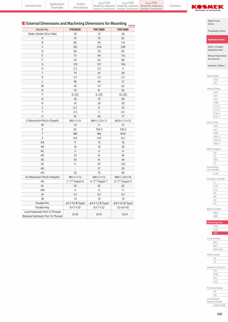
Model No.Slider Stroke (One Side)
ABCDEFGHJKLMNPQRSTU
V (Nominal×Pitch×Depth)WXYZAAABACADAEAFAGAH
AJ (Nominal×Pitch×Depth)AKALAMJAJB
Parallel PinParallel Key
Lock Hydraulic Port:G ThreadRelease Hydraulic Port:G Thread
FVC06301055801826075541293.5192.54042298 50166.52.542
M6×1×91082M86.89165343471-50
M6×1×125 Depth 6
5693.514
φ5×10 (B Type)8×7×20
FVC10001570942347094631573.5242.54454418 70248560
M8×1.25×1111104.5M86.8131664141973775
M6×1×126 Depth 7
6594.519
φ6×12 (B Type)8×7×32
G1/4 G1/4G1/8
FVC1600208211429882116801964302.557625610 9030104.577
M10×1.5×1515136.5M108.51620849491305090
M8×1.25×168 Depth 9
82114.519
φ8×16 (B Type)10×8×45
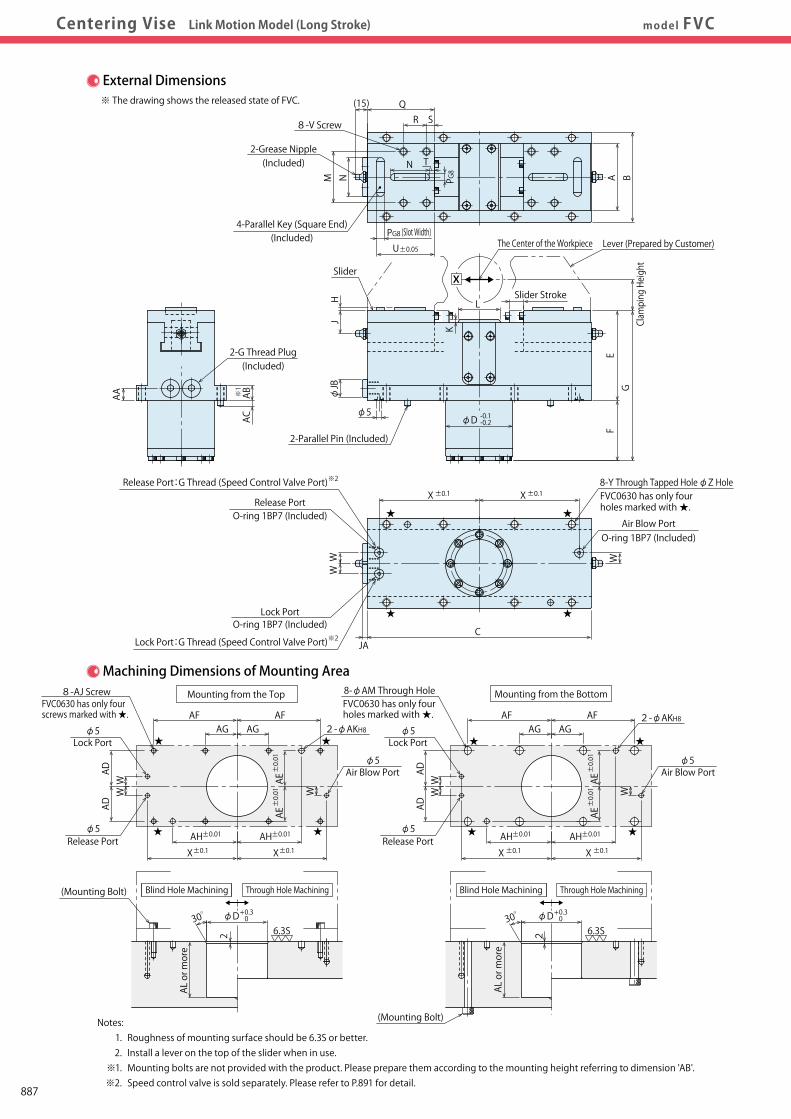
(mm)External Dimensions and Machining Dimensions for Mounting
+ 0.027+ 0.005
+ 0.027+ 0.005
+ 0.027+ 0.005
+ 0.018 0
+ 0.022 0
+ 0.018 0
QR S
(15)
TN
M N
LSlider Stroke
The Center of the Workpiece
φD -0.1-0.2
AA
GClamping Height
FE
ABAC
4-Parallel Key (Square End)(Included)
8-V Screw
X±0.1 X±0.1
CJA
U±0.05
PG8
PG8
2-Parallel Pin (Included)
JH
Air Blow Port
Release PortO-ring 1BP7 (Included)
O-ring 1BP7 (Included)
O-ring 1BP7 (Included)Lock Port
8-Y Through Tapped HoleφZ Hole
Slider
※1
※2
φ5
φJB
BA
W
WW
Release Port:G Thread (Speed Control Valve Port)
※2Lock Port:G Thread (Speed Control Valve Port)
Lever (Prepared by Customer)
X
K
★
★
FVC0630 has only fourholes marked with ★.★
★
External Dimensions※ The drawing shows the released state of FVC.
2-Grease Nipple(Included)
2-G Thread Plug
(Slot Width)
(Included)
6.3S
2
φD+ 0.3 0
AL or more
AL or more
30゜ 30゜6.3S2
Through Hole Machining
8-φAM Through Hole
AG AGAF AF
AG AGAF AF
AH±0.01
X±0.1AH±0.01
X±0.1AH±0.01
X ±0.1AH±0.01
X ±0.1
Air Blow Port
8-AJ Screw
2-φAKH82-φAKH8
φ5
φ5Air Blow Port
φ5
φ5
Lock Portφ5
Lock Port
WW W
ADAD
WW
ADAD
Release Port
AE±0.01AE±0.01
AE±0.01AE±0.01
(Mounting Bolt)
(Mounting Bolt)
Machining Dimensions of Mounting Area
W
φ5Release Port
φD+ 0.3 0
Notes: 1. Roughness of mounting surface should be 6.3S or better. 2. Install a lever on the top of the slider when in use. ※1. Mounting bolts are not provided with the product. Please prepare them according to the mounting height referring to dimension 'AB'. ※2. Speed control valve is sold separately. Please refer to P.891 for detail.
FVC0630 has only four holes marked with ★.
★
★
★
★
★
★
★
★
Mounting from the Top Mounting from the Bottom
Through Hole Machining
FVC0630 has only four screws marked with ★.
Blind Hole Machining Blind Hole Machining
887
Work Support
LDLCTNCTC
Swing Clamp
LHA
Pneumatic Series
Hydraulic Series
Valve / CouplerHydraulic Unit
Cautions / Others
High-PowerSeries
Manual OperationAccessories
Hole Clamp
SFASFC
Link Clamp
LKALKCLKWLM/LJTMA-2TMA-1
Block Cylinder
DBADBC
Control Valve
BZLBZTBZX/JZG
Pallet Clamp
VSVT
Expansion Locating Pin
VFLVFMVFJVFK
FPFQ
Pull Stud Clamp
FVAFVDFVC
Centering Vise
DWA/DWB
CustomizedSpring Cylinder
LHCLHSLHWLT/LGTLA-2TLB-2TLA-1
LLW
Air SensingLift Cylinder
Compact Cylinder
LLLLRLLUDPDRDSDT
Introduction ApplicationExamples
ActionDescription Cautions
Model FVAModel No. IndicationSpecifications・External Dimensions
Model FVDModel No. IndicationSpecifications・External Dimensions
Model FVCModel No. IndicationSpecifications・External DimensionsCentering Vise Link Motion Model (Long Stroke) model FVC
Model No.Slider Stroke (One Side)
ABCDEFGHJKLMNPQRSTU
V (Nominal×Pitch×Depth)WXYZAAABACADAEAFAGAH
AJ (Nominal×Pitch×Depth)AKALAMJAJB
Parallel PinParallel Key
Lock Hydraulic Port:G ThreadRelease Hydraulic Port:G Thread
FVC06301055801826075541293.5192.54042298 50166.52.542
M6×1×91082M86.89165343471-50
M6×1×125 Depth 6
5693.514
φ5×10 (B Type)8×7×20
FVC10001570942347094631573.5242.54454418 70248560
M8×1.25×1111104.5M86.8131664141973775
M6×1×126 Depth 7
6594.519
φ6×12 (B Type)8×7×32
G1/4 G1/4G1/8
FVC1600208211429882116801964302.557625610 9030104.577
M10×1.5×1515136.5M108.51620849491305090
M8×1.25×168 Depth 9
82114.519
φ8×16 (B Type)10×8×45
(mm)External Dimensions and Machining Dimensions for Mounting
+ 0.027+ 0.005
+ 0.027+ 0.005
+ 0.027+ 0.005
+ 0.018 0
+ 0.022 0
+ 0.018 0
QR S
(15)
TN
M N
LSlider Stroke
The Center of the Workpiece
φD -0.1-0.2
AA
GClamping Height
FE
ABAC
4-Parallel Key (Square End)(Included)
8-V Screw
X±0.1 X±0.1
CJA
U±0.05
PG8
PG8
2-Parallel Pin (Included)
JH
Air Blow Port
Release PortO-ring 1BP7 (Included)
O-ring 1BP7 (Included)
O-ring 1BP7 (Included)Lock Port
8-Y Through Tapped HoleφZ Hole
Slider
※1
※2
φ5
φJB
BA
W
WW
Release Port:G Thread (Speed Control Valve Port)
※2Lock Port:G Thread (Speed Control Valve Port)
Lever (Prepared by Customer)
X
K
★
★
FVC0630 has only fourholes marked with ★.★
★
External Dimensions※ The drawing shows the released state of FVC.
2-Grease Nipple(Included)
2-G Thread Plug
(Slot Width)
(Included)
6.3S
2
φD+ 0.3 0
AL or more
AL or more
30゜ 30゜6.3S2
Through Hole Machining
8-φAM Through Hole
AG AGAF AF
AG AGAF AF
AH±0.01
X±0.1AH±0.01
X±0.1AH±0.01
X ±0.1AH±0.01
X ±0.1
Air Blow Port
8-AJ Screw
2-φAKH82-φAKH8
φ5
φ5Air Blow Port
φ5
φ5
Lock Portφ5
Lock Port
WW W
ADAD
WW
ADAD
Release Port
AE±0.01AE±0.01
AE±0.01AE±0.01
(Mounting Bolt)
(Mounting Bolt)
Machining Dimensions of Mounting Area
W
φ5Release Port
φD+ 0.3 0
Notes: 1. Roughness of mounting surface should be 6.3S or better. 2. Install a lever on the top of the slider when in use. ※1. Mounting bolts are not provided with the product. Please prepare them according to the mounting height referring to dimension 'AB'. ※2. Speed control valve is sold separately. Please refer to P.891 for detail.
FVC0630 has only four holes marked with ★.
★
★
★
★
★
★
★
★
Mounting from the Top Mounting from the Bottom
Through Hole Machining
FVC0630 has only four screws marked with ★.
Blind Hole Machining Blind Hole Machining
888
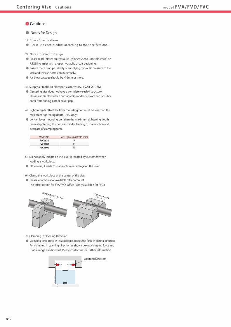
Work Support
LDLCTNCTC
Swing Clamp
LHA
Pneumatic Series
Hydraulic Series
Valve / CouplerHydraulic Unit
Cautions / Others
High-PowerSeries
Manual OperationAccessories
Hole Clamp
SFASFC
Link Clamp
LKALKCLKWLM/LJTMA-2TMA-1
Block Cylinder
DBADBC
Control Valve
BZLBZTBZX/JZG
Pallet Clamp
VSVT
Expansion Locating Pin
VFLVFMVFJVFK
FPFQ
Pull Stud Clamp
FVAFVDFVC
Centering Vise
DWA/DWB
CustomizedSpring Cylinder
LHCLHSLHWLT/LGTLA-2TLB-2TLA-1
LLW
Air SensingLift Cylinder
Compact Cylinder
LLLLRLLUDPDRDSDT
Introduction ApplicationExamples
ActionDescription Cautions
Model FVAModel No. IndicationSpecifications・External Dimensions
Model FVDModel No. IndicationSpecifications・External Dimensions
Model FVCModel No. IndicationSpecifications・External Dimensionsmodel FVA/FVD/FVCCentering Vise Cautions
● Installation Notes
1)Check the Usable Fluid
● Please use the appropriate fluid by referring to the Hydraulic Fluid List
(P.1237).
2) Filling the Grease
● Fill the grease from the grease nipple or lubrication port before use,
and operate the centering vise 2 or 3 times without a workpiece.
Use the grease of lithium soap thickened, mineral oil grease fortified
with MoS2. (Recommended Grease:MOLYKOTE® BR-2 PLUS made
by TORAY・DOW CORNING)
If too much grease is applied it may be overflowed from the gap of
body and slider during operation.
3) Installation/Removal of the Lever (Prepared by Customer)
● Use hexagon socket bolts for mounting (with tensile strength of 12.9)
and tighten them with the torque shown in the chart below. Installation
failure causes the deformaiton of lever and decrease of clamping force.
4)Mounting the Centering Vise
● When mounting the centering vise, use hexagon socket bolts as multiple
bolt holes for mounting (with tensile strength of 12.9) and tighten them
with the torque shown in the chart below. Tightening with greater torque
than recommended can depress the seating surface or break the bolt.
Tightening Torque (N・m)102550102550255080
Thread SizeM6×1M8×1.25M10×1.5M6×1M8×1.25M10×1.5M8×1.25M10×1.5M12×1.75
Model No.FVA0401FVA0631FVA1001FVC0630FVC1000FVC1600FVD1600FVD2500FVD4000
FVA
FVC
FVD
Tightening Torque (N・m)6.36.310101025102550
Thread SizeM5×0.8M5×0.8M6×1M6×1M6×1M8×1.25M6×1M8×1.25M10×1.5
Model No.FVA0401FVA0631FVA1001FVC0630FVC1000FVC1600FVD1600FVD2500FVD4000
FVA
FVC
FVD
<When Mounting from the Top>
Tightening Torque (N・m)252525252550255080
Thread SizeM8×1.25M8×1.25M8×1.25M8×1.25M8×1.25M10×1.5M8×1.25M10×1.5M12×1.75
Model No.FVA0401FVA0631FVA1001FVC0630FVC1000FVC1600FVD1600FVD2500FVD4000
FVA
FVC
FVD
<When Mounting from the Bottom>
※ This drawing shows FVC.
Cautions
● Notes for Design
1)Check Specifications
● Please use each product according to the specifications.
2)Notes for Circuit Design
● Please read "Notes on Hydraulic Cylinder Speed Control Circuit" on
P.1238 to assist with proper hydraulic circuit designing.
● Ensure there is no possibility of supplying hydraulic pressure to the
lock and release ports simultaneously.
● Air blow passage should be φ6mm or more.
3)Supply air to the air blow port as necessary. (FVA/FVC Only)
● Centering Vise does not have a completely sealed structure.
Please use air blow when cutting chips and/or coolant can possibly
enter from sliding part or cover gap.
4)Tightening depth of the lever mounting bolt must be less than the
maximum tightening depth. (FVC Only)
● Longer lever mounting bolt than the maximum tightening depth
causes tightening the body and slider leading to malfunction and
decrease of clamping force.
5)Do not apply impact on the lever (prepared by customer) when
loading a workpiece.
● Otherwise, it leads to malfunction or damage on the lever.
6)Clamp the workpiece at the center of the vise.
● Please contact us for available offset amount.
(No offset option for FVA/FVD. Offset is only available for FVC.)
7)Clamping in Opening Direction
● Clamping force curve in this catalog indicates the force in closing direction.
For clamping in opening direction as shown below, clamping force and
usable range are different. Please contact us for further information.
Max. Tightening Depth (mm)91115
Model No.FVC0630FVC1000FVC1600
Offset Amount
The Center of the Vise
Mountingfrom the Top
Mountingfrom the Bottom
5)Operating Speed Adjustment
● Excessive operating speed of the centering vise may lead to wear-
out or damage the internal components. Please adjust the operating
speed so that the slider fully strokes within 1~2 seconds.
● Install a flow control valve and gradually control the flow rate from
the low-speed side (small flow) to the designated speed. Controlling
from the high-speed side (large flow) causes excessive surge pressure
or overload to the centering vise leading to damage of a machine or
device.
● When controlling the speed with the flow control valve, make sure
there is no excessively high pressure in the hydraulic circuit.
● Speed control may not be conducted if there is excessive air in the
hydraulic circuit.
● The viscosity of fluid will decrease when its temperature increases.
This will accelerate the operating speed of the centering vise.
Adjust the speed under the proper temperature condition.
Opening Direction
・ Installation Notes ・ Hydraulic Fluid List ・ Notes on Hydraulic Cylinder Speed Control Circuit・ Notes on Handling ・ Maintenance/Inspection ・ Warranty
※ Please refer to P.1237 for common cautions.
889
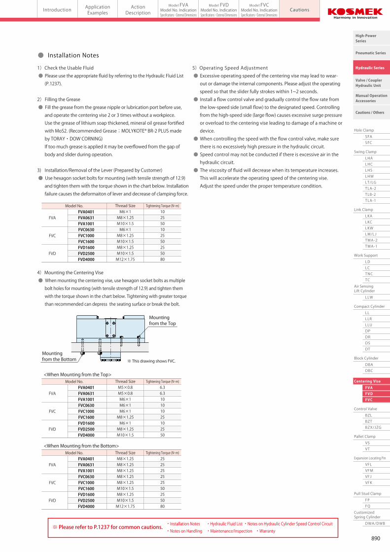
Work Support
LDLCTNCTC
Swing Clamp
LHA
Pneumatic Series
Hydraulic Series
Valve / CouplerHydraulic Unit
Cautions / Others
High-PowerSeries
Manual OperationAccessories
Hole Clamp
SFASFC
Link Clamp
LKALKCLKWLM/LJTMA-2TMA-1
Block Cylinder
DBADBC
Control Valve
BZLBZTBZX/JZG
Pallet Clamp
VSVT
Expansion Locating Pin
VFLVFMVFJVFK
FPFQ
Pull Stud Clamp
FVAFVDFVC
Centering Vise
DWA/DWB
CustomizedSpring Cylinder
LHCLHSLHWLT/LGTLA-2TLB-2TLA-1
LLW
Air SensingLift Cylinder
Compact Cylinder
LLLLRLLUDPDRDSDT
Introduction ApplicationExamples
ActionDescription Cautions
Model FVAModel No. IndicationSpecifications・External Dimensions
Model FVDModel No. IndicationSpecifications・External Dimensions
Model FVCModel No. IndicationSpecifications・External Dimensionsmodel FVA/FVD/FVCCentering Vise Cautions
● Installation Notes
1)Check the Usable Fluid
● Please use the appropriate fluid by referring to the Hydraulic Fluid List
(P.1237).
2) Filling the Grease
● Fill the grease from the grease nipple or lubrication port before use,
and operate the centering vise 2 or 3 times without a workpiece.
Use the grease of lithium soap thickened, mineral oil grease fortified
with MoS2. (Recommended Grease:MOLYKOTE® BR-2 PLUS made
by TORAY・DOW CORNING)
If too much grease is applied it may be overflowed from the gap of
body and slider during operation.
3) Installation/Removal of the Lever (Prepared by Customer)
● Use hexagon socket bolts for mounting (with tensile strength of 12.9)
and tighten them with the torque shown in the chart below. Installation
failure causes the deformaiton of lever and decrease of clamping force.
4)Mounting the Centering Vise
● When mounting the centering vise, use hexagon socket bolts as multiple
bolt holes for mounting (with tensile strength of 12.9) and tighten them
with the torque shown in the chart below. Tightening with greater torque
than recommended can depress the seating surface or break the bolt.
Tightening Torque (N・m)102550102550255080
Thread SizeM6×1M8×1.25M10×1.5M6×1M8×1.25M10×1.5M8×1.25M10×1.5M12×1.75
Model No.FVA0401FVA0631FVA1001FVC0630FVC1000FVC1600FVD1600FVD2500FVD4000
FVA
FVC
FVD
Tightening Torque (N・m)6.36.310101025102550
Thread SizeM5×0.8M5×0.8M6×1M6×1M6×1M8×1.25M6×1M8×1.25M10×1.5
Model No.FVA0401FVA0631FVA1001FVC0630FVC1000FVC1600FVD1600FVD2500FVD4000
FVA
FVC
FVD
<When Mounting from the Top>
Tightening Torque (N・m)252525252550255080
Thread SizeM8×1.25M8×1.25M8×1.25M8×1.25M8×1.25M10×1.5M8×1.25M10×1.5M12×1.75
Model No.FVA0401FVA0631FVA1001FVC0630FVC1000FVC1600FVD1600FVD2500FVD4000
FVA
FVC
FVD
<When Mounting from the Bottom>
※ This drawing shows FVC.
Cautions
● Notes for Design
1)Check Specifications
● Please use each product according to the specifications.
2)Notes for Circuit Design
● Please read "Notes on Hydraulic Cylinder Speed Control Circuit" on
P.1238 to assist with proper hydraulic circuit designing.
● Ensure there is no possibility of supplying hydraulic pressure to the
lock and release ports simultaneously.
● Air blow passage should be φ6mm or more.
3)Supply air to the air blow port as necessary. (FVA/FVC Only)
● Centering Vise does not have a completely sealed structure.
Please use air blow when cutting chips and/or coolant can possibly
enter from sliding part or cover gap.
4)Tightening depth of the lever mounting bolt must be less than the
maximum tightening depth. (FVC Only)
● Longer lever mounting bolt than the maximum tightening depth
causes tightening the body and slider leading to malfunction and
decrease of clamping force.
5)Do not apply impact on the lever (prepared by customer) when
loading a workpiece.
● Otherwise, it leads to malfunction or damage on the lever.
6)Clamp the workpiece at the center of the vise.
● Please contact us for available offset amount.
(No offset option for FVA/FVD. Offset is only available for FVC.)
7)Clamping in Opening Direction
● Clamping force curve in this catalog indicates the force in closing direction.
For clamping in opening direction as shown below, clamping force and
usable range are different. Please contact us for further information.
Max. Tightening Depth (mm)91115
Model No.FVC0630FVC1000FVC1600
Offset Amount
The Center of the Vise
Mountingfrom the Top
Mountingfrom the Bottom
5)Operating Speed Adjustment
● Excessive operating speed of the centering vise may lead to wear-
out or damage the internal components. Please adjust the operating
speed so that the slider fully strokes within 1~2 seconds.
● Install a flow control valve and gradually control the flow rate from
the low-speed side (small flow) to the designated speed. Controlling
from the high-speed side (large flow) causes excessive surge pressure
or overload to the centering vise leading to damage of a machine or
device.
● When controlling the speed with the flow control valve, make sure
there is no excessively high pressure in the hydraulic circuit.
● Speed control may not be conducted if there is excessive air in the
hydraulic circuit.
● The viscosity of fluid will decrease when its temperature increases.
This will accelerate the operating speed of the centering vise.
Adjust the speed under the proper temperature condition.
Opening Direction
・ Installation Notes ・ Hydraulic Fluid List ・ Notes on Hydraulic Cylinder Speed Control Circuit・ Notes on Handling ・ Maintenance/Inspection ・ Warranty
※ Please refer to P.1237 for common cautions.
890
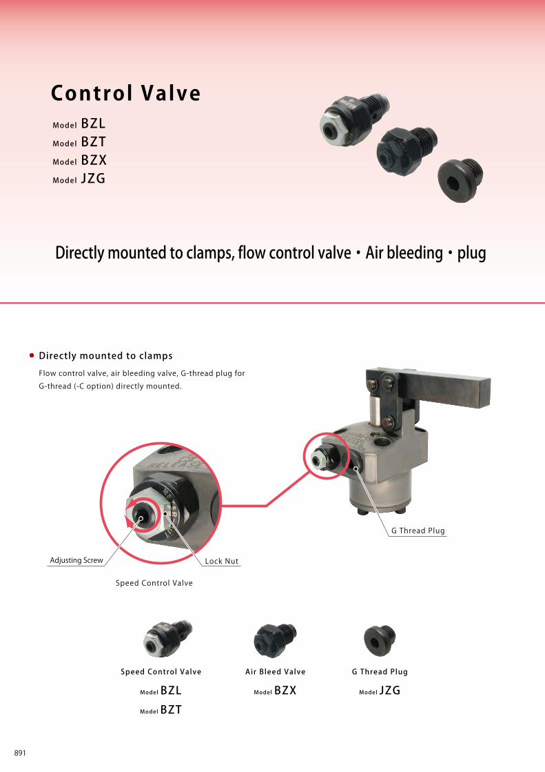
Work Support
LDLCTNCTC
Swing Clamp
LHA
Pneumatic Series
Hydraulic Series
Valve / CouplerHydraulic Unit
Cautions / Others
High-PowerSeries
Manual OperationAccessories
Hole Clamp
SFASFC
Link Clamp
LKALKCLKWLM/LJTMA-2TMA-1
Block Cylinder
DBADBC
Pallet Clamp
VSVT
Expansion Locating Pin
VFLVFMVFJVFK
FPFQ
Pull Stud Clamp
FVAFVDFVC
Centering Vise
DWA/DWB
CustomizedSpring Cylinder
LHCLHSLHWLT/LGTLA-2TLB-2TLA-1
LLW
Air SensingLift Cylinder
Compact Cylinder
LLLLRLLUDPDRDSDT
Control Valve
BZLBZTBZX/JZG
Control ValveDigest
Model BZLModel BZTModel BZXModel JZG
Directly mounted to clamps, flow control valve・Air bleeding・plug
Control Valve
Model BZL
Speed Control Valve(For Low Pressure)
OperatingPressure Range Action Description
7MPa or less
Model BZL
Model BZT
Speed Control Valve
Model BZX
Air Bleed Valve
Model JZG
G Thread Plug
Flow control valve, air bleeding valve, G-thread plug for
G-thread (-C option) directly mounted.
Directly mounted to clamps
Lock NutAdjusting Screw
G Thread Plug
Adjust the f low by wrench.
It can adjust the clamping action speed individually.
Flow Control
Air bleeding in the circuit is possible
by loosening f low control valve.
Air bleeding in the circuit is possible by wrench.
Air bleeding in the circuit is possible
by loosening G thread plug.
35MPa or less
25MPa or less
35MPa or less
Model BZT
Speed Control Valve(For High Pressure)
Model BZX
Air Bleed Valve
Model JZG
G Thread Plug
Speed Control Valve
Clamps→ P.893
→ P.897
→ P.899
→ P.901
891
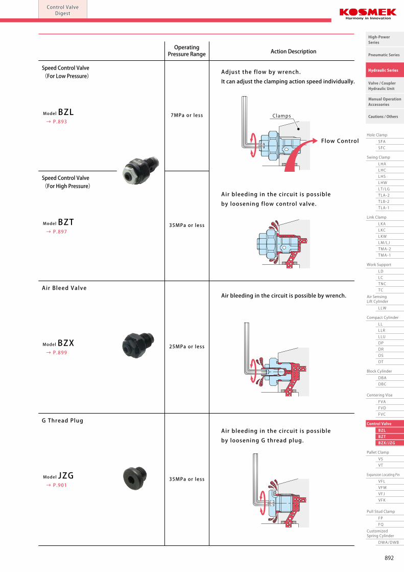
Work Support
LDLCTNCTC
Swing Clamp
LHA
Pneumatic Series
Hydraulic Series
Valve / CouplerHydraulic Unit
Cautions / Others
High-PowerSeries
Manual OperationAccessories
Hole Clamp
SFASFC
Link Clamp
LKALKCLKWLM/LJTMA-2TMA-1
Block Cylinder
DBADBC
Pallet Clamp
VSVT
Expansion Locating Pin
VFLVFMVFJVFK
FPFQ
Pull Stud Clamp
FVAFVDFVC
Centering Vise
DWA/DWB
CustomizedSpring Cylinder
LHCLHSLHWLT/LGTLA-2TLB-2TLA-1
LLW
Air SensingLift Cylinder
Compact Cylinder
LLLLRLLUDPDRDSDT
Control Valve
BZLBZTBZX/JZG
Control ValveDigest
Model BZLModel BZTModel BZXModel JZG
Directly mounted to clamps, flow control valve・Air bleeding・plug
Control Valve
Model BZL
Speed Control Valve(For Low Pressure)
OperatingPressure Range Action Description
7MPa or less
Model BZL
Model BZT
Speed Control Valve
Model BZX
Air Bleed Valve
Model JZG
G Thread Plug
Flow control valve, air bleeding valve, G-thread plug for
G-thread (-C option) directly mounted.
Directly mounted to clamps
Lock NutAdjusting Screw
G Thread Plug
Adjust the f low by wrench.
It can adjust the clamping action speed individually.
Flow Control
Air bleeding in the circuit is possible
by loosening f low control valve.
Air bleeding in the circuit is possible by wrench.
Air bleeding in the circuit is possible
by loosening G thread plug.
35MPa or less
25MPa or less
35MPa or less
Model BZT
Speed Control Valve(For High Pressure)
Model BZX
Air Bleed Valve
Model JZG
G Thread Plug
Speed Control Valve
Clamps→ P.893
→ P.897
→ P.899
→ P.901
892
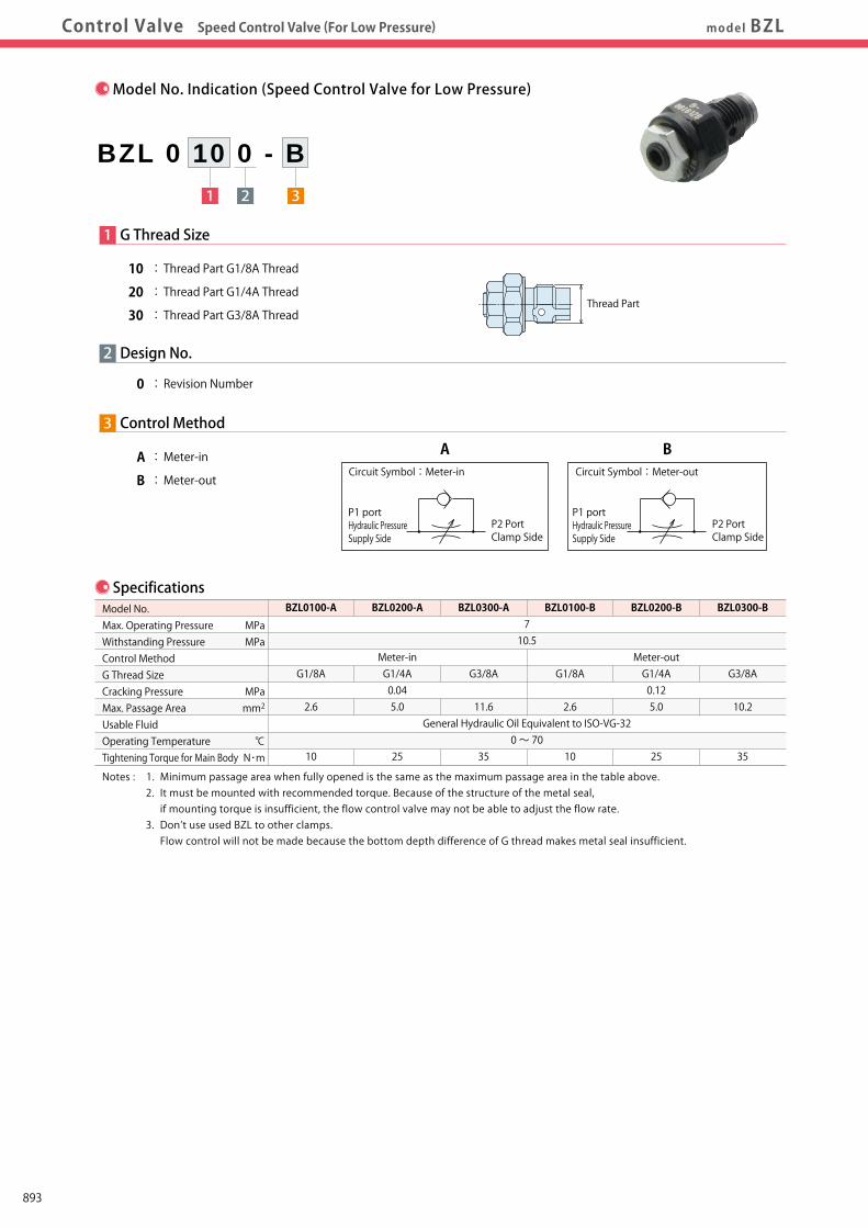
Work Support
LDLCTNCTC
Swing Clamp
LHA
Pneumatic Series
Hydraulic Series
Valve / CouplerHydraulic Unit
Cautions / Others
High-PowerSeries
Manual OperationAccessories
Hole Clamp
SFASFC
Link Clamp
LKALKCLKWLM/LJTMA-2TMA-1
Block Cylinder
DBADBC
Pallet Clamp
VSVT
Expansion Locating Pin
VFLVFMVFJVFK
FPFQ
Pull Stud Clamp
FVAFVDFVC
Centering Vise
DWA/DWB
CustomizedSpring Cylinder
LHCLHSLHWLT/LGTLA-2TLB-2TLA-1
LLW
Air SensingLift Cylinder
Compact Cylinder
LLLLRLLUDPDRDSDT
Control Valve
BZLBZTBZX/JZG
Control ValveDigest
Model No.IndicationModel No.Indication SpecificationsSpecifications External
DimensionsFlow Rate GraphApplicableProductsApplicableProductsControl Valve Speed Control Valve (For Low Pressure) model BZL
Specifications
MPaMPa
MPamm2
℃N・m
BZL0100-A
G1/8A
2.6
10
BZL0200-A
Meter-inG1/4A0.045.0
25
710.5
General Hydraulic Oil Equivalent to ISO-VG-320 ~ 70
BZL0300-A
G3/8A
11.6
35
BZL0100-B
G1/8A
2.6
10
BZL0200-B
Meter-outG1/4A0.125.0
25
BZL0300-B
G3/8A
10.2
35
Model No.Max. Operating PressureWithstanding PressureControl MethodG Thread SizeCracking PressureMax. Passage AreaUsable FluidOperating Temperature Tightening Torque for Main Body
Notes : 1. Minimum passage area when fully opened is the same as the maximum passage area in the table above. 2. It must be mounted with recommended torque. Because of the structure of the metal seal, if mounting torque is insufficient, the flow control valve may not be able to adjust the flow rate. 3. Don’t use used BZL to other clamps. Flow control will not be made because the bottom depth difference of G thread makes metal seal insufficient.
Model No. Indication (Speed Control Valve for Low Pressure)
1 2 3
BZL 0 10 0 - B
2
1 G Thread Size
10 : Thread Part G1/8A Thread
20 : Thread Part G1/4A Thread
30 : Thread Part G3/8A Thread
0 : Revision Number
Design No.
3 Control Method
A : Meter-in
B : Meter-out
P1 portHydraulic PressureSupply Side
P2 PortClamp Side
Circuit Symbol:Meter-in
Thread Part
P1 portHydraulic PressureSupply Side
P2 PortClamp Side
Circuit Symbol:Meter-out
A B
Applicable Products
Note : 1. Flow control circuit for double action cylinder should have meter-out circuits for both the lock and release sides (except model LKE/TLA/TMA). Meter-in circuits can be adversely affected by any air in the system.
LC (Single Action)Work SupportLC0262-C□LC0302-C□LC0362-C□LC0402-C□□-□LC0482-C□□-□LC0552-C□□-□LC0652-C□□-□
LC0752-C□□-□LC0902-C□□-□
DBC (Double Action)Block Cylinder(DBC0250-C□)(DBC0320-C□)
DBC0250-C□DBC0320-C□
(DBC0400-C□)(DBC0500-C□)DBC0400-C□DBC0500-C□
FVA (Double Action)Centering Vise(FVA0401)(FVA0631)(FVA1001)
FVA0401FVA0631FVA1001
FVC (Double Action)Centering Vise(FVC0630)
FVC0630
(FVC1000)(FVC1600)FVC1000FVC1600
FVD (Double Action)Centering Vise(FVD1600)(FVD2500)
FVD1600FVD2500
(FVD4000)
FVD4000
DBA (Double Action)Block Cylinder(DBA0250-C□)(DBA0320-C□)
DBA0250-C□DBA0320-C□
(DBA0400-C□)(DBA0500-C□)DBA0400-C□DBA0500-C□
Model No.
BZL0100-A
BZL0100-B
BZL0200-A
BZL0200-B
BZL0300-A
BZL0300-B
LHA (Double Action)Swing Clamp(LHA0360-C□□-□)(LHA0400-C□□-□)(LHA0480-C□□-□)(LHA0550-C□□-□)
LHA0360-C□□-□LHA0400-C□□-□LHA0480-C□□-□LHA0550-C□□-□
(LHA0650-C□□-□)(LHA0750-C□□-□)LHA0650-C□□-□LHA0750-C□□-□(LHA0900-C□□-□)(LHA1050-C□□-□)LHA0900-C□□-□LHA1050-C□□-□
LHC (Double Action)Swing Clamp(LHC0360-C□□-□)(LHC0400-C□□-□)(LHC0480-C□□-□)(LHC0550-C□□-□)
LHC0360-C□□-□LHC0400-C□□-□LHC0480-C□□-□LHC0550-C□□-□
(LHC0650-C□□-□)
LHC0650-C□□-□
Model No.
BZL0100-A
BZL0100-B
BZL0200-A
BZL0200-B
BZL0300-A
BZL0300-B
LKE (Double Action)High-Power Link ClampLKE0300-C□LKE0360-C□LKE0400-C□LKE0480-C□LKE0550-C□
LKC (Double Action)Link Clamp
(LKC0400-C□-□)(LKC0480-C□-□)(LKC0550-C□-□)
LKC0400-C□-□LKC0480-C□-□LKC0550-C□-□
(LKC0650-C□-□)
LKC0650-C□-□
LKA (Double Action)Link Clamp
(LKA0360-C□□-□)(LKA0400-C□□-□)(LKA0480-C□□-□)(LKA0550-C□□-□)
LKA0360-C□□-□LKA0400-C□□-□LKA0480-C□□-□LKA0550-C□□-□
(LKA0650-C□□-□)(LKA0750-C□□-□)LKA0650-C□□-□LKA0750-C□□-□(LKA0900-C□□-□)(LKA1050-C□□-□)LKA0900-C□□-□LKA1050-C□□-□
LT (Single Action)Swing ClampLT0301-C□-□LT036□-C□-□LT040□-C□-□LT048□-C□-□LT055□-C□-□
LT065□-C□-□LT075□-C□-□
LG (Single Action)Swing ClampLG0301-C□-□LG036□-C□-□LG040□-C□-□LG048□-C□-□LG055□-C□-□
LG065□-C□-□LG075□-C□-□
LG090□-C□-□LG105□-C□-□
Model No.
BZL0100-A
BZL0100-B
BZL0200-A
BZL0200-B
BZL0300-A
BZL0300-B
LL (Double Action)Linear Cylinder( LL0360-C□□-□ )( LL0400-C□□-□ )( LL0480-C□□-□ )( LL0550-C□□-□ )
LL0360-C□□-□LL0400-C□□-□LL0480-C□□-□LL0550-C□□-□
( LL0650-C□□-□ )( LL0750-C□□-□ )LL0650-C□□-□LL0750-C□□-□
( LL0900-C□□-□ )( LL1050-C□□-□ )LL0900-C□□-□LL1050-C□□-□
LLR (Double Action)Linear Cylinder(LLR0360-C□□-□-□)(LLR0400-C□□-□-□)(LLR0480-C□□-□-□)(LLR0550-C□□-□-□)
LLR0360-C□□-□-□LLR0400-C□□-□-□LLR0480-C□□-□-□LLR0550-C□□-□-□(LLR0650-C□□-□-□)(LLR0750-C□□-□-□)LLR0650-C□□-□-□LLR0750-C□□-□-□
(LLR0900-C□□-□-□)(LLR1050-C□□-□-□)LLR0900-C□□-□-□LLR1050-C□□-□-□
LLW (Double Action)Lift Cylinder
(LLW036□-C□□-□)(LLW040□-C□□-□)(LLW048□-C□□-□)
LLW036□-C□□-□LLW040□-C□□-□LLW048□-C□□-□
LKW (Double Action)Link Clamp
(LKW040□-C□□-□)(LKW048□-C□□-□)(LKW055□-C□□-□)
LKW040□-C□□-□LKW048□-C□□-□LKW055□-C□□-□
(LKW065□-C□□-□)(LKW0751-C□□-□)LKW065□-C□□-□LKW0751-C□□-□
LM (Single Action)Link ClampLM0300-C□LM0360-C□LM0400-C□LM0480-C□LM0550-C□
LM0650-C□LM0750-C□
LJ (Single Action)Link ClampLJ0302-C□LJ0362-C□LJ0402-C□LJ0482-C□LJ0552-C□
LM0652-C□LM0752-C□
LJ0902-C□LJ1052-C□
LHS (Double Action)Swing Clamp
(LHS0360-C□□-□)(LHS0400-C□□-□)(LHS0480-C□□-□)(LHS0550-C□□-□)
LHS0360-C□□-□LHS0400-C□□-□LHS0480-C□□-□LHS0550-C□□-□
(LHS0650-C□□-□)(LHS0750-C□□-□)LHS0650-C□□-□LHS0750-C□□-□(LHS0900-C□□-□)(LHS1050-C□□-□)LHS0900-C□□-□LHS1050-C□□-□
LHE (Double Action)High-Power Swing Clamp
LHE0300-C□LHE0360-C□LHE0400-C□LHE0480-C□LHE0550-C□
LHW (Double Action)Swing Clamp(LHW040□-C□□-□)(LHW048□-C□□-□)(LHW055□-C□□-□)
LHW040□-C□□-□LHW048□-C□□-□LHW055□-C□□-□
(LHW065□-C□□-□)(LHW0751-C□□-□)LHW065□-C□□-□LHW0751-C□□-□
893
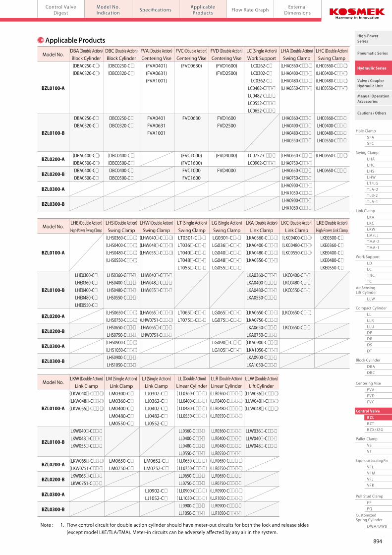
Work Support
LDLCTNCTC
Swing Clamp
LHA
Pneumatic Series
Hydraulic Series
Valve / CouplerHydraulic Unit
Cautions / Others
High-PowerSeries
Manual OperationAccessories
Hole Clamp
SFASFC
Link Clamp
LKALKCLKWLM/LJTMA-2TMA-1
Block Cylinder
DBADBC
Pallet Clamp
VSVT
Expansion Locating Pin
VFLVFMVFJVFK
FPFQ
Pull Stud Clamp
FVAFVDFVC
Centering Vise
DWA/DWB
CustomizedSpring Cylinder
LHCLHSLHWLT/LGTLA-2TLB-2TLA-1
LLW
Air SensingLift Cylinder
Compact Cylinder
LLLLRLLUDPDRDSDT
Control Valve
BZLBZTBZX/JZG
Control ValveDigest
Model No.IndicationModel No.Indication SpecificationsSpecifications External
DimensionsFlow Rate GraphApplicableProductsApplicableProductsControl Valve Speed Control Valve (For Low Pressure) model BZL
Specifications
MPaMPa
MPamm2
℃N・m
BZL0100-A
G1/8A
2.6
10
BZL0200-A
Meter-inG1/4A0.045.0
25
710.5
General Hydraulic Oil Equivalent to ISO-VG-320 ~ 70
BZL0300-A
G3/8A
11.6
35
BZL0100-B
G1/8A
2.6
10
BZL0200-B
Meter-outG1/4A0.125.0
25
BZL0300-B
G3/8A
10.2
35
Model No.Max. Operating PressureWithstanding PressureControl MethodG Thread SizeCracking PressureMax. Passage AreaUsable FluidOperating Temperature Tightening Torque for Main Body
Notes : 1. Minimum passage area when fully opened is the same as the maximum passage area in the table above. 2. It must be mounted with recommended torque. Because of the structure of the metal seal, if mounting torque is insufficient, the flow control valve may not be able to adjust the flow rate. 3. Don’t use used BZL to other clamps. Flow control will not be made because the bottom depth difference of G thread makes metal seal insufficient.
Model No. Indication (Speed Control Valve for Low Pressure)
1 2 3
BZL 0 10 0 - B
2
1 G Thread Size
10 : Thread Part G1/8A Thread
20 : Thread Part G1/4A Thread
30 : Thread Part G3/8A Thread
0 : Revision Number
Design No.
3 Control Method
A : Meter-in
B : Meter-out
P1 portHydraulic PressureSupply Side
P2 PortClamp Side
Circuit Symbol:Meter-in
Thread Part
P1 portHydraulic PressureSupply Side
P2 PortClamp Side
Circuit Symbol:Meter-out
A B
Applicable Products
Note : 1. Flow control circuit for double action cylinder should have meter-out circuits for both the lock and release sides (except model LKE/TLA/TMA). Meter-in circuits can be adversely affected by any air in the system.
LC (Single Action)Work SupportLC0262-C□LC0302-C□LC0362-C□LC0402-C□□-□LC0482-C□□-□LC0552-C□□-□LC0652-C□□-□
LC0752-C□□-□LC0902-C□□-□
DBC (Double Action)Block Cylinder(DBC0250-C□)(DBC0320-C□)
DBC0250-C□DBC0320-C□
(DBC0400-C□)(DBC0500-C□)DBC0400-C□DBC0500-C□
FVA (Double Action)Centering Vise(FVA0401)(FVA0631)(FVA1001)
FVA0401FVA0631FVA1001
FVC (Double Action)Centering Vise(FVC0630)
FVC0630
(FVC1000)(FVC1600)FVC1000FVC1600
FVD (Double Action)Centering Vise(FVD1600)(FVD2500)
FVD1600FVD2500
(FVD4000)
FVD4000
DBA (Double Action)Block Cylinder(DBA0250-C□)(DBA0320-C□)
DBA0250-C□DBA0320-C□
(DBA0400-C□)(DBA0500-C□)DBA0400-C□DBA0500-C□
Model No.
BZL0100-A
BZL0100-B
BZL0200-A
BZL0200-B
BZL0300-A
BZL0300-B
LHA (Double Action)Swing Clamp(LHA0360-C□□-□)(LHA0400-C□□-□)(LHA0480-C□□-□)(LHA0550-C□□-□)
LHA0360-C□□-□LHA0400-C□□-□LHA0480-C□□-□LHA0550-C□□-□
(LHA0650-C□□-□)(LHA0750-C□□-□)LHA0650-C□□-□LHA0750-C□□-□(LHA0900-C□□-□)(LHA1050-C□□-□)LHA0900-C□□-□LHA1050-C□□-□
LHC (Double Action)Swing Clamp(LHC0360-C□□-□)(LHC0400-C□□-□)(LHC0480-C□□-□)(LHC0550-C□□-□)
LHC0360-C□□-□LHC0400-C□□-□LHC0480-C□□-□LHC0550-C□□-□
(LHC0650-C□□-□)
LHC0650-C□□-□
Model No.
BZL0100-A
BZL0100-B
BZL0200-A
BZL0200-B
BZL0300-A
BZL0300-B
LKE (Double Action)High-Power Link ClampLKE0300-C□LKE0360-C□LKE0400-C□LKE0480-C□LKE0550-C□
LKC (Double Action)Link Clamp
(LKC0400-C□-□)(LKC0480-C□-□)(LKC0550-C□-□)
LKC0400-C□-□LKC0480-C□-□LKC0550-C□-□
(LKC0650-C□-□)
LKC0650-C□-□
LKA (Double Action)Link Clamp
(LKA0360-C□□-□)(LKA0400-C□□-□)(LKA0480-C□□-□)(LKA0550-C□□-□)
LKA0360-C□□-□LKA0400-C□□-□LKA0480-C□□-□LKA0550-C□□-□
(LKA0650-C□□-□)(LKA0750-C□□-□)LKA0650-C□□-□LKA0750-C□□-□(LKA0900-C□□-□)(LKA1050-C□□-□)LKA0900-C□□-□LKA1050-C□□-□
LT (Single Action)Swing ClampLT0301-C□-□LT036□-C□-□LT040□-C□-□LT048□-C□-□LT055□-C□-□
LT065□-C□-□LT075□-C□-□
LG (Single Action)Swing ClampLG0301-C□-□LG036□-C□-□LG040□-C□-□LG048□-C□-□LG055□-C□-□
LG065□-C□-□LG075□-C□-□
LG090□-C□-□LG105□-C□-□
Model No.
BZL0100-A
BZL0100-B
BZL0200-A
BZL0200-B
BZL0300-A
BZL0300-B
LL (Double Action)Linear Cylinder( LL0360-C□□-□ )( LL0400-C□□-□ )( LL0480-C□□-□ )( LL0550-C□□-□ )
LL0360-C□□-□LL0400-C□□-□LL0480-C□□-□LL0550-C□□-□
( LL0650-C□□-□ )( LL0750-C□□-□ )LL0650-C□□-□LL0750-C□□-□
( LL0900-C□□-□ )( LL1050-C□□-□ )LL0900-C□□-□LL1050-C□□-□
LLR (Double Action)Linear Cylinder(LLR0360-C□□-□-□)(LLR0400-C□□-□-□)(LLR0480-C□□-□-□)(LLR0550-C□□-□-□)
LLR0360-C□□-□-□LLR0400-C□□-□-□LLR0480-C□□-□-□LLR0550-C□□-□-□(LLR0650-C□□-□-□)(LLR0750-C□□-□-□)LLR0650-C□□-□-□LLR0750-C□□-□-□
(LLR0900-C□□-□-□)(LLR1050-C□□-□-□)LLR0900-C□□-□-□LLR1050-C□□-□-□
LLW (Double Action)Lift Cylinder
(LLW036□-C□□-□)(LLW040□-C□□-□)(LLW048□-C□□-□)
LLW036□-C□□-□LLW040□-C□□-□LLW048□-C□□-□
LKW (Double Action)Link Clamp
(LKW040□-C□□-□)(LKW048□-C□□-□)(LKW055□-C□□-□)
LKW040□-C□□-□LKW048□-C□□-□LKW055□-C□□-□
(LKW065□-C□□-□)(LKW0751-C□□-□)LKW065□-C□□-□LKW0751-C□□-□
LM (Single Action)Link ClampLM0300-C□LM0360-C□LM0400-C□LM0480-C□LM0550-C□
LM0650-C□LM0750-C□
LJ (Single Action)Link ClampLJ0302-C□LJ0362-C□LJ0402-C□LJ0482-C□LJ0552-C□
LM0652-C□LM0752-C□
LJ0902-C□LJ1052-C□
LHS (Double Action)Swing Clamp
(LHS0360-C□□-□)(LHS0400-C□□-□)(LHS0480-C□□-□)(LHS0550-C□□-□)
LHS0360-C□□-□LHS0400-C□□-□LHS0480-C□□-□LHS0550-C□□-□
(LHS0650-C□□-□)(LHS0750-C□□-□)LHS0650-C□□-□LHS0750-C□□-□(LHS0900-C□□-□)(LHS1050-C□□-□)LHS0900-C□□-□LHS1050-C□□-□
LHE (Double Action)High-Power Swing Clamp
LHE0300-C□LHE0360-C□LHE0400-C□LHE0480-C□LHE0550-C□
LHW (Double Action)Swing Clamp(LHW040□-C□□-□)(LHW048□-C□□-□)(LHW055□-C□□-□)
LHW040□-C□□-□LHW048□-C□□-□LHW055□-C□□-□
(LHW065□-C□□-□)(LHW0751-C□□-□)LHW065□-C□□-□LHW0751-C□□-□
894
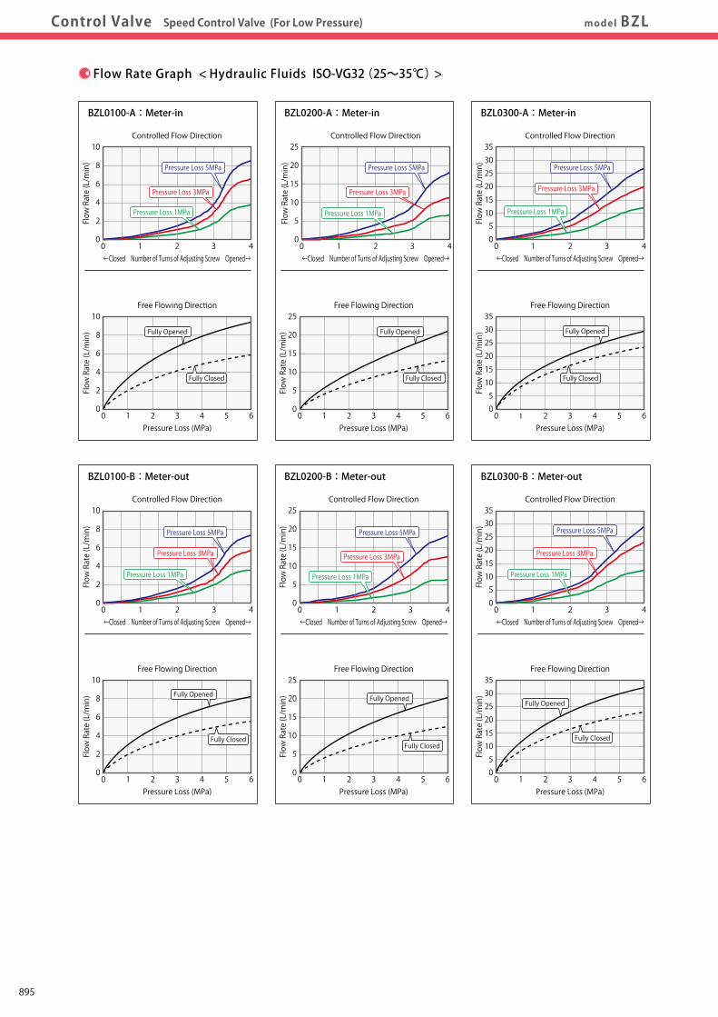
Work Support
LDLCTNCTC
Swing Clamp
LHA
Pneumatic Series
Hydraulic Series
Valve / CouplerHydraulic Unit
Cautions / Others
High-PowerSeries
Manual OperationAccessories
Hole Clamp
SFASFC
Link Clamp
LKALKCLKWLM/LJTMA-2TMA-1
Block Cylinder
DBADBC
Pallet Clamp
VSVT
Expansion Locating Pin
VFLVFMVFJVFK
FPFQ
Pull Stud Clamp
FVAFVDFVC
Centering Vise
DWA/DWB
CustomizedSpring Cylinder
LHCLHSLHWLT/LGTLA-2TLB-2TLA-1
LLW
Air SensingLift Cylinder
Compact Cylinder
LLLLRLLUDPDRDSDT
Control Valve
BZLBZTBZX/JZG
Control ValveDigest
Model No.Indication Specifications External
DimensionsExternalDimensionsFlow Rate GraphFlow Rate GraphApplicable
ProductsControl Valve Speed Control Valve (For Low Pressure) model BZL
External Dimensions
Machining Dimensions of Mounting Area
Model No.ABCDEFGHJKL
M (Nominal×Pitch)NPQ
R (Flat Surface Area)STUVW
BZL0100-□ BZL0200-□ BZL0300-□ 14 18 22 15.5 20 24 15 16 19 12 13 16 8.5 9.5 11 (11.6) (15.1) (17.6) G1/8 G1/4 G3/8 3 3 3 3.5 3.5 5 10 10 13 3 3 4 M6×0.75 M6×0.75 M8×0.75 11.5 15 17.5 8.5 11※1 13 9 11.5 13 16 20.5 24.5 10 13.5 17 8.7 11.5 15 G1/8 G1/4 G3/8 2 ~ 3 3 ~ 4 4 ~ 5 2.5 ~ 5 3.5 ~ 7 4.5 ~ 9
Notes : 1. Since the area is sealing part, be careful not to damage it. 2. Since the area is the metal sealing part of BZL, be careful not to damage it. (Especially when deburring) 3. No cutting chips or burr should be at the tolerance part of machining hole. 4. As shown in the drawing, P1 port is used as the hydraulic supply and P2 port as the clamp side. 5. If mounting plugs or fittings with G thread specification available in the market, the dimension '※1' should be 12.5.
Adjusting Screw
0.2
45°
0.4
BZL0□00
-□
(Clamp/Cylinder)
G ThreadExclusive Packing(Included)
P2 PortClamp Side
Fmax.H
max.CDEJ
φB
Hex. Socket L
M Screw
Hexagon KHexagon A
φT
max.φS
min.φR
φVQ
P1 PortHydraulic PressureSupply Side
φW
P2 PortClamp Side
U Thread(Prepared HoleφTFlat Bottom)
min.PNZ
Z⊥ 0.1
Attention 0- 0.10
OPENCLOSE
P1 PortHydraulic PressureSupply Side (mm)
Notes 1. Please read "Notes on Hydraulic Cylinder Speed Control Circuit" to assist with proper hydraulic circuit design.
If there is something wrong with the circuit design, it leads to the applications malfunction and damage. (Refer to P.1238)
2. It is dangerous to air bleed during operation under high pressure. It must be done under lower pressure.
(For reference: the minimum operating range of the product within the circuit.)
Free Flowing Direction
0
2
4
6
8
10
10 2 3 4 5 6Pressure Loss (MPa)
Flow Rate (L/min)
Controlled Flow Direction
0
2
4
6
8
10
10 2 3 4←Closed Number of Turns of Adjusting Screw Opened→
Flow Rate (L/min)
Controlled Flow Direction
0
5
15
10
20
30
25
35
10 2 3 4←Closed Number of Turns of Adjusting Screw Opened→
Flow Rate (L/min)
Controlled Flow Direction
0
5
10
15
20
25
10 2 3 4←Closed Number of Turns of Adjusting Screw Opened→
Flow Rate (L/min)
Controlled Flow Direction
0
2
4
6
8
10
10 2 3 4←Closed Number of Turns of Adjusting Screw Opened→
Flow Rate (L/min)
Controlled Flow Direction
0
5
15
10
20
3025
35
10 2 3 4←Closed Number of Turns of Adjusting Screw Opened→
Flow Rate (L/min)
Controlled Flow Direction
0
5
10
15
20
25
10 2 3 4←Closed Number of Turns of Adjusting Screw Opened→
Flow Rate (L/min)
Free Flowing Direction
0
5
10
15
20
25
10 2 3 4 5 6Pressure Loss (MPa)
Flow Rate (L/min)
Free Flowing Direction
0
15105
20
3025
35
10 2 3 4 5 6Pressure Loss (MPa)
Flow Rate (L/min)
Free Flowing Direction
051015
20253035
10 2 3 4 5 6Pressure Loss (MPa)
Flow Rate (L/min)
Free Flowing Direction
0
5
10
15
20
25
10 2 3 4 5 6Pressure Loss (MPa)
Flow Rate (L/min)
Free Flowing Direction
0
2
4
6
8
10
10 2 3 4 5 6Pressure Loss (MPa)
Flow Rate (L/min)
BZL0100-A:Meter-in BZL0200-A:Meter-in BZL0300-A:Meter-in
BZL0100-B:Meter-out BZL0200-B:Meter-out BZL0300-B:Meter-out
Flow Rate Graph < Hydraulic Fluids ISO-VG32(25~35℃)>
Fully Closed
Fully OpenedFully OpenedFully Opened
Fully OpenedFully OpenedFully Opened
Fully ClosedFully Closed
Fully ClosedFully Closed
Fully Closed
Pressure Loss 5MPa Pressure Loss 5MPa Pressure Loss 5MPa
Pressure Loss 5MPaPressure Loss 5MPaPressure Loss 5MPa
Pressure Loss 3MPa Pressure Loss 3MPa Pressure Loss 3MPa
Pressure Loss 3MPaPressure Loss 3MPaPressure Loss 3MPa
Pressure Loss 1MPa Pressure Loss 1MPa Pressure Loss 1MPa
Pressure Loss 1MPaPressure Loss 1MPaPressure Loss 1MPa
895
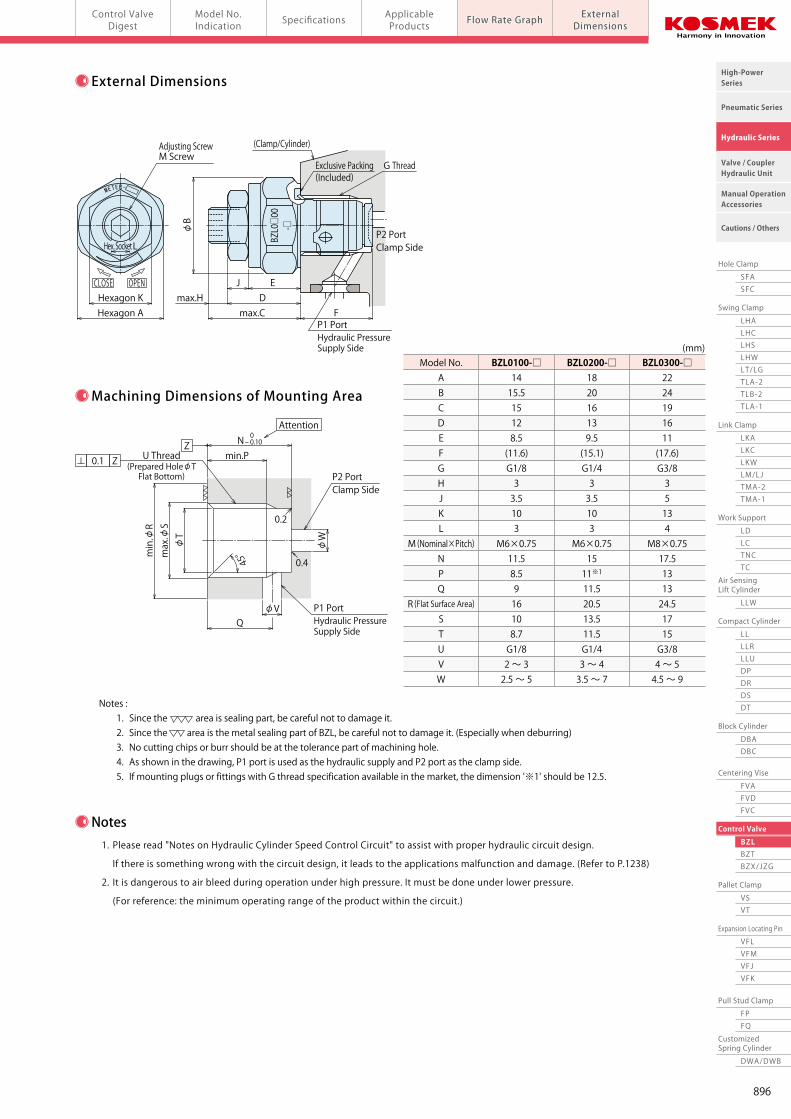
Work Support
LDLCTNCTC
Swing Clamp
LHA
Pneumatic Series
Hydraulic Series
Valve / CouplerHydraulic Unit
Cautions / Others
High-PowerSeries
Manual OperationAccessories
Hole Clamp
SFASFC
Link Clamp
LKALKCLKWLM/LJTMA-2TMA-1
Block Cylinder
DBADBC
Pallet Clamp
VSVT
Expansion Locating Pin
VFLVFMVFJVFK
FPFQ
Pull Stud Clamp
FVAFVDFVC
Centering Vise
DWA/DWB
CustomizedSpring Cylinder
LHCLHSLHWLT/LGTLA-2TLB-2TLA-1
LLW
Air SensingLift Cylinder
Compact Cylinder
LLLLRLLUDPDRDSDT
Control Valve
BZLBZTBZX/JZG
Control ValveDigest
Model No.Indication Specifications External
DimensionsExternalDimensionsFlow Rate GraphFlow Rate GraphApplicable
ProductsControl Valve Speed Control Valve (For Low Pressure) model BZL
External Dimensions
Machining Dimensions of Mounting Area
Model No.ABCDEFGHJKL
M (Nominal×Pitch)NPQ
R (Flat Surface Area)STUVW
BZL0100-□ BZL0200-□ BZL0300-□ 14 18 22 15.5 20 24 15 16 19 12 13 16 8.5 9.5 11 (11.6) (15.1) (17.6) G1/8 G1/4 G3/8 3 3 3 3.5 3.5 5 10 10 13 3 3 4 M6×0.75 M6×0.75 M8×0.75 11.5 15 17.5 8.5 11※1 13 9 11.5 13 16 20.5 24.5 10 13.5 17 8.7 11.5 15 G1/8 G1/4 G3/8 2 ~ 3 3 ~ 4 4 ~ 5 2.5 ~ 5 3.5 ~ 7 4.5 ~ 9
Notes : 1. Since the area is sealing part, be careful not to damage it. 2. Since the area is the metal sealing part of BZL, be careful not to damage it. (Especially when deburring) 3. No cutting chips or burr should be at the tolerance part of machining hole. 4. As shown in the drawing, P1 port is used as the hydraulic supply and P2 port as the clamp side. 5. If mounting plugs or fittings with G thread specification available in the market, the dimension '※1' should be 12.5.
Adjusting Screw
0.2
45°
0.4
BZL0□00
- □
(Clamp/Cylinder)
G ThreadExclusive Packing(Included)
P2 PortClamp Side
Fmax.H
max.CDEJ
φB
Hex. Socket L
M Screw
Hexagon KHexagon A
φT
max.φS
min.φR
φVQ
P1 PortHydraulic PressureSupply Side
φW
P2 PortClamp Side
U Thread(Prepared HoleφTFlat Bottom)
min.PNZ
Z⊥ 0.1
Attention 0- 0.10
OPENCLOSE
P1 PortHydraulic PressureSupply Side (mm)
Notes 1. Please read "Notes on Hydraulic Cylinder Speed Control Circuit" to assist with proper hydraulic circuit design.
If there is something wrong with the circuit design, it leads to the applications malfunction and damage. (Refer to P.1238)
2. It is dangerous to air bleed during operation under high pressure. It must be done under lower pressure.
(For reference: the minimum operating range of the product within the circuit.)
Free Flowing Direction
0
2
4
6
8
10
10 2 3 4 5 6Pressure Loss (MPa)
Flow Rate (L/min)
Controlled Flow Direction
0
2
4
6
8
10
10 2 3 4←Closed Number of Turns of Adjusting Screw Opened→
Flow Rate (L/min)
Controlled Flow Direction
0
5
15
10
20
30
25
35
10 2 3 4←Closed Number of Turns of Adjusting Screw Opened→
Flow Rate (L/min)
Controlled Flow Direction
0
5
10
15
20
25
10 2 3 4←Closed Number of Turns of Adjusting Screw Opened→
Flow Rate (L/min)
Controlled Flow Direction
0
2
4
6
8
10
10 2 3 4←Closed Number of Turns of Adjusting Screw Opened→
Flow Rate (L/min)
Controlled Flow Direction
0
5
15
10
20
3025
35
10 2 3 4←Closed Number of Turns of Adjusting Screw Opened→
Flow Rate (L/min)
Controlled Flow Direction
0
5
10
15
20
25
10 2 3 4←Closed Number of Turns of Adjusting Screw Opened→
Flow Rate (L/min)
Free Flowing Direction
0
5
10
15
20
25
10 2 3 4 5 6Pressure Loss (MPa)
Flow Rate (L/min)
Free Flowing Direction
0
15105
20
3025
35
10 2 3 4 5 6Pressure Loss (MPa)
Flow Rate (L/min)
Free Flowing Direction
051015
20253035
10 2 3 4 5 6Pressure Loss (MPa)
Flow Rate (L/min)
Free Flowing Direction
0
5
10
15
20
25
10 2 3 4 5 6Pressure Loss (MPa)
Flow Rate (L/min)
Free Flowing Direction
0
2
4
6
8
10
10 2 3 4 5 6Pressure Loss (MPa)
Flow Rate (L/min)
BZL0100-A:Meter-in BZL0200-A:Meter-in BZL0300-A:Meter-in
BZL0100-B:Meter-out BZL0200-B:Meter-out BZL0300-B:Meter-out
Flow Rate Graph < Hydraulic Fluids ISO-VG32(25~35℃)>
Fully Closed
Fully OpenedFully OpenedFully Opened
Fully OpenedFully OpenedFully Opened
Fully ClosedFully Closed
Fully ClosedFully Closed
Fully Closed
Pressure Loss 5MPa Pressure Loss 5MPa Pressure Loss 5MPa
Pressure Loss 5MPaPressure Loss 5MPaPressure Loss 5MPa
Pressure Loss 3MPa Pressure Loss 3MPa Pressure Loss 3MPa
Pressure Loss 3MPaPressure Loss 3MPaPressure Loss 3MPa
Pressure Loss 1MPa Pressure Loss 1MPa Pressure Loss 1MPa
Pressure Loss 1MPaPressure Loss 1MPaPressure Loss 1MPa
896
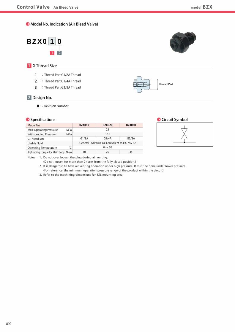
Work Support
LDLCTNCTC
Swing Clamp
LHA
Pneumatic Series
Hydraulic Series
Valve / CouplerHydraulic Unit
Cautions / Others
High-PowerSeries
Manual OperationAccessories
Hole Clamp
SFASFC
Link Clamp
LKALKCLKWLM/LJTMA-2TMA-1
Block Cylinder
DBADBC
Pallet Clamp
VSVT
Expansion Locating Pin
VFLVFMVFJVFK
FPFQ
Pull Stud Clamp
FVAFVDFVC
Centering Vise
DWA/DWB
CustomizedSpring Cylinder
LHCLHSLHWLT/LGTLA-2TLB-2TLA-1
LLW
Air SensingLift Cylinder
Compact Cylinder
LLLLRLLUDPDRDSDT
Control Valve
BZLBZTBZX/JZG
Control ValveDigest P.891 Model No. IndicationModel No. Indication SpecificationsSpecifications External DimensionsExternal DimensionsApplicable ProductsApplicable ProductsControl Valve Air Bleed Valve model BZX
Model No. Indication (Air Bleed Valve)
Specifications Circuit Symbol
1 2
BZX0 1 0
2
1 G Thread Size
1 : Thread Part G1/8A Thread
2 : Thread Part G1/4A Thread
3 : Thread Part G3/8A Thread
0 : Revision Number
Design No.
MPaMPa
℃N・m
BZX010
G1/8A
10
BZX0202537.5G1/4A
General Hydraulic Oil Equivalent to ISO-VG-320 ~ 7025
BZX030
G3/8A
35
Model No.Max. Operating PressureWithstanding PressureG Thread SizeUsable FluidOperating Temperature Tightening Torque for Main Body
Notes : 1. Do not over loosen the plug during air venting. (Do not loosen for more than 2 turns from the fully closed position.) 2. It is dangerous to have air venting operation under high pressure. It must be done under lower pressure. (For reference: the minimum operation pressure range of the product within the circuit) 3. Refer to the machining dimensions for BZL mounting area.
Thread Part
External Dimensions
Model No.ABCDEG
BZX010 BZX020 BZX030 14 18 22 15.5 20 24 19.8 20.6 20.6 9.3 10.1 10.1 5.5 6.3 6.3 G1/8 G1/4 G3/8
(mm)
Applicable Products
LKA (Double Action)Link ClampLKA0360-C□□-□LKA0400-C□□-□LKA0480-C□□-□LKA0550-C□□-□
LKA0650-C□□-□LKA0750-C□□-□LKA0900-C□□-□LKA1050-C□□-□
LT (Single Action)Swing ClampLT0301-C□-□LT036□-C□-□LT040□-C□-□LT048□-C□-□LT055□-C□-□LT065□-C□-□LT075□-C□-□
LG (Single Action)Swing ClampLG0301-C□-□LG036□-C□-□LG040□-C□-□LG048□-C□-□LG055□-C□-□LG065□-C□-□LG075□-C□-□LG090□-C□-□LG105□-C□-□
Model No.
BZX010
BZX020
BZX030
LKC (Double Action)Link ClampLKC0400-C□-□LKC0480-C□-□LKC0550-C□-□
LKC0650-C□-□
LKE (Double Action)High-Power Link ClampLKE0300-C□LKE0360-C□LKE0400-C□LKE0480-C□LKE0550-C□
LC (Single Action)Work SupportLC0262-C□LC0302-C□LC0362-C□LC0402-C□□-□LC0482-C□□-□LC0552-C□□-□LC0652-C□□-□LC0752-C□□-□LC0902-C□□-□
DBA (Double Action)Block CylinderDBA0250-C□DBA0320-C□
DBA0400-C□DBA0500-C□
DBC (Double Action)Block CylinderDBC0250-C□DBC0320-C□
DBC0400-C□DBC0500-C□
FVA (Double Action)Centering ViseFVA0401FVA0631FVA1001
FVC (Double Action)Centering ViseFVC0630
FVC1000FVC1600
FVD (Double Action)Centering ViseFVD1600FVD2500
FVD4000
Model No.
BZX010
BZX020
BZX030
LHA (Double Action)Swing ClampLHA0360-C□□-□LHA0400-C□□-□LHA0480-C□□-□LHA0550-C□□-□
LHA0650-C□□-□LHA0750-C□□-□LHA0900-C□□-□LHA1050-C□□-□
LHC (Double Action)Swing ClampLHC0360-C□□-□LHC0400-C□□-□LHC0480-C□□-□LHC0550-C□□-□
LHC0650-C□□-□
LHE (Double Action)High-Power Swing ClampLHE0300-C□LHE0360-C□LHE0400-C□LHE0480-C□LHE0550-C□
LHW (Double Action)Swing ClampLHW040□-C□□-□LHW048□-C□□-□LHW055□-C□□-□
LHW065□-C□□-□LHW0751-C□□-□
LHS (Double Action)Swing ClampLHS0360-C□□-□LHS0400-C□□-□LHS0480-C□□-□LHS0550-C□□-□
LHS0650-C□□-□LHS0750-C□□-□LHS0900-C□□-□LHS1050-C□□-□
Model No.
BZX010
BZX020
BZX030
LL (Double Action)Linear CylinderLL0360-C□□-□LL0400-C□□-□LL0480-C□□-□LL0550-C□□-□
LL0650-C□□-□LL0750-C□□-□LL0900-C□□-□LL1050-C□□-□
LLR (Double Action)Linear CylinderLLR0360-C□□-□-□LLR0400-C□□-□-□LLR0480-C□□-□-□LLR0550-C□□-□-□
LLR0650-C□□-□-□LLR0750-C□□-□-□LLR0900-C□□-□-□LLR1050-C□□-□-□
LLW (Double Action)Lift CylinderLLW036□-C□□-□LLW040□-C□□-□LLW048□-C□□-□
LKW (Double Action)Link Clamp
LKW040□-C□□-□LKW048□-C□□-□LKW055□-C□□-□
LKW065□-C□□-□LKW0751-C□□-□
LM (Single Action)Link ClampLM0300-C□LM0360-C□LM0400-C□LM0480-C□LM0550-C□LM0650-C□LM0750-C□
LJ (Single Action)Link ClampLJ0302-C□LJ0362-C□LJ0402-C□LJ0482-C□LJ0552-C□LJ0652-C□LJ0752-C□LJ0902-C□LJ1052-C□
G Thread
Exclusive Packing (Included)
Lock NutM6 (3 types)
Hexagon AHexagon 10Hex. Socket 3
10.5E
3.63.8D
C
φB
BodyPlugM6×1
(Clamp / Cylinder)
899
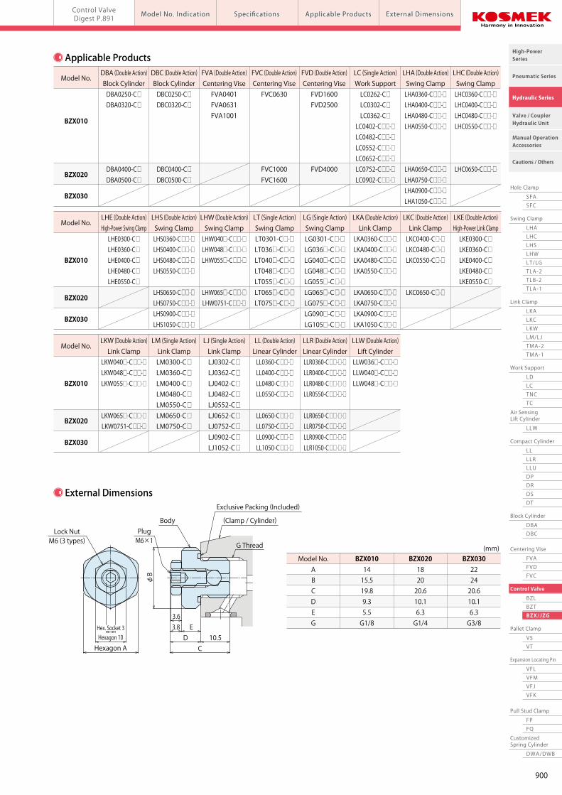
Work Support
LDLCTNCTC
Swing Clamp
LHA
Pneumatic Series
Hydraulic Series
Valve / CouplerHydraulic Unit
Cautions / Others
High-PowerSeries
Manual OperationAccessories
Hole Clamp
SFASFC
Link Clamp
LKALKCLKWLM/LJTMA-2TMA-1
Block Cylinder
DBADBC
Pallet Clamp
VSVT
Expansion Locating Pin
VFLVFMVFJVFK
FPFQ
Pull Stud Clamp
FVAFVDFVC
Centering Vise
DWA/DWB
CustomizedSpring Cylinder
LHCLHSLHWLT/LGTLA-2TLB-2TLA-1
LLW
Air SensingLift Cylinder
Compact Cylinder
LLLLRLLUDPDRDSDT
Control Valve
BZLBZTBZX/JZG
Control ValveDigest P.891 Model No. IndicationModel No. Indication SpecificationsSpecifications External DimensionsExternal DimensionsApplicable ProductsApplicable ProductsControl Valve Air Bleed Valve model BZX
Model No. Indication (Air Bleed Valve)
Specifications Circuit Symbol
1 2
BZX0 1 0
2
1 G Thread Size
1 : Thread Part G1/8A Thread
2 : Thread Part G1/4A Thread
3 : Thread Part G3/8A Thread
0 : Revision Number
Design No.
MPaMPa
℃N・m
BZX010
G1/8A
10
BZX0202537.5G1/4A
General Hydraulic Oil Equivalent to ISO-VG-320 ~ 7025
BZX030
G3/8A
35
Model No.Max. Operating PressureWithstanding PressureG Thread SizeUsable FluidOperating Temperature Tightening Torque for Main Body
Notes : 1. Do not over loosen the plug during air venting. (Do not loosen for more than 2 turns from the fully closed position.) 2. It is dangerous to have air venting operation under high pressure. It must be done under lower pressure. (For reference: the minimum operation pressure range of the product within the circuit) 3. Refer to the machining dimensions for BZL mounting area.
Thread Part
External Dimensions
Model No.ABCDEG
BZX010 BZX020 BZX030 14 18 22 15.5 20 24 19.8 20.6 20.6 9.3 10.1 10.1 5.5 6.3 6.3 G1/8 G1/4 G3/8
(mm)
Applicable Products
LKA (Double Action)Link ClampLKA0360-C□□-□LKA0400-C□□-□LKA0480-C□□-□LKA0550-C□□-□
LKA0650-C□□-□LKA0750-C□□-□LKA0900-C□□-□LKA1050-C□□-□
LT (Single Action)Swing ClampLT0301-C□-□LT036□-C□-□LT040□-C□-□LT048□-C□-□LT055□-C□-□LT065□-C□-□LT075□-C□-□
LG (Single Action)Swing ClampLG0301-C□-□LG036□-C□-□LG040□-C□-□LG048□-C□-□LG055□-C□-□LG065□-C□-□LG075□-C□-□LG090□-C□-□LG105□-C□-□
Model No.
BZX010
BZX020
BZX030
LKC (Double Action)Link ClampLKC0400-C□-□LKC0480-C□-□LKC0550-C□-□
LKC0650-C□-□
LKE (Double Action)High-Power Link ClampLKE0300-C□LKE0360-C□LKE0400-C□LKE0480-C□LKE0550-C□
LC (Single Action)Work SupportLC0262-C□LC0302-C□LC0362-C□LC0402-C□□-□LC0482-C□□-□LC0552-C□□-□LC0652-C□□-□LC0752-C□□-□LC0902-C□□-□
DBA (Double Action)Block CylinderDBA0250-C□DBA0320-C□
DBA0400-C□DBA0500-C□
DBC (Double Action)Block CylinderDBC0250-C□DBC0320-C□
DBC0400-C□DBC0500-C□
FVA (Double Action)Centering ViseFVA0401FVA0631FVA1001
FVC (Double Action)Centering ViseFVC0630
FVC1000FVC1600
FVD (Double Action)Centering ViseFVD1600FVD2500
FVD4000
Model No.
BZX010
BZX020
BZX030
LHA (Double Action)Swing ClampLHA0360-C□□-□LHA0400-C□□-□LHA0480-C□□-□LHA0550-C□□-□
LHA0650-C□□-□LHA0750-C□□-□LHA0900-C□□-□LHA1050-C□□-□
LHC (Double Action)Swing ClampLHC0360-C□□-□LHC0400-C□□-□LHC0480-C□□-□LHC0550-C□□-□
LHC0650-C□□-□
LHE (Double Action)High-Power Swing ClampLHE0300-C□LHE0360-C□LHE0400-C□LHE0480-C□LHE0550-C□
LHW (Double Action)Swing ClampLHW040□-C□□-□LHW048□-C□□-□LHW055□-C□□-□
LHW065□-C□□-□LHW0751-C□□-□
LHS (Double Action)Swing ClampLHS0360-C□□-□LHS0400-C□□-□LHS0480-C□□-□LHS0550-C□□-□
LHS0650-C□□-□LHS0750-C□□-□LHS0900-C□□-□LHS1050-C□□-□
Model No.
BZX010
BZX020
BZX030
LL (Double Action)Linear CylinderLL0360-C□□-□LL0400-C□□-□LL0480-C□□-□LL0550-C□□-□
LL0650-C□□-□LL0750-C□□-□LL0900-C□□-□LL1050-C□□-□
LLR (Double Action)Linear CylinderLLR0360-C□□-□-□LLR0400-C□□-□-□LLR0480-C□□-□-□LLR0550-C□□-□-□
LLR0650-C□□-□-□LLR0750-C□□-□-□LLR0900-C□□-□-□LLR1050-C□□-□-□
LLW (Double Action)Lift CylinderLLW036□-C□□-□LLW040□-C□□-□LLW048□-C□□-□
LKW (Double Action)Link Clamp
LKW040□-C□□-□LKW048□-C□□-□LKW055□-C□□-□
LKW065□-C□□-□LKW0751-C□□-□
LM (Single Action)Link ClampLM0300-C□LM0360-C□LM0400-C□LM0480-C□LM0550-C□LM0650-C□LM0750-C□
LJ (Single Action)Link ClampLJ0302-C□LJ0362-C□LJ0402-C□LJ0482-C□LJ0552-C□LJ0652-C□LJ0752-C□LJ0902-C□LJ1052-C□
G Thread
Exclusive Packing (Included)
Lock NutM6 (3 types)
Hexagon AHexagon 10Hex. Socket 3
10.5E
3.63.8D
C
φB
BodyPlugM6×1
(Clamp / Cylinder)
900
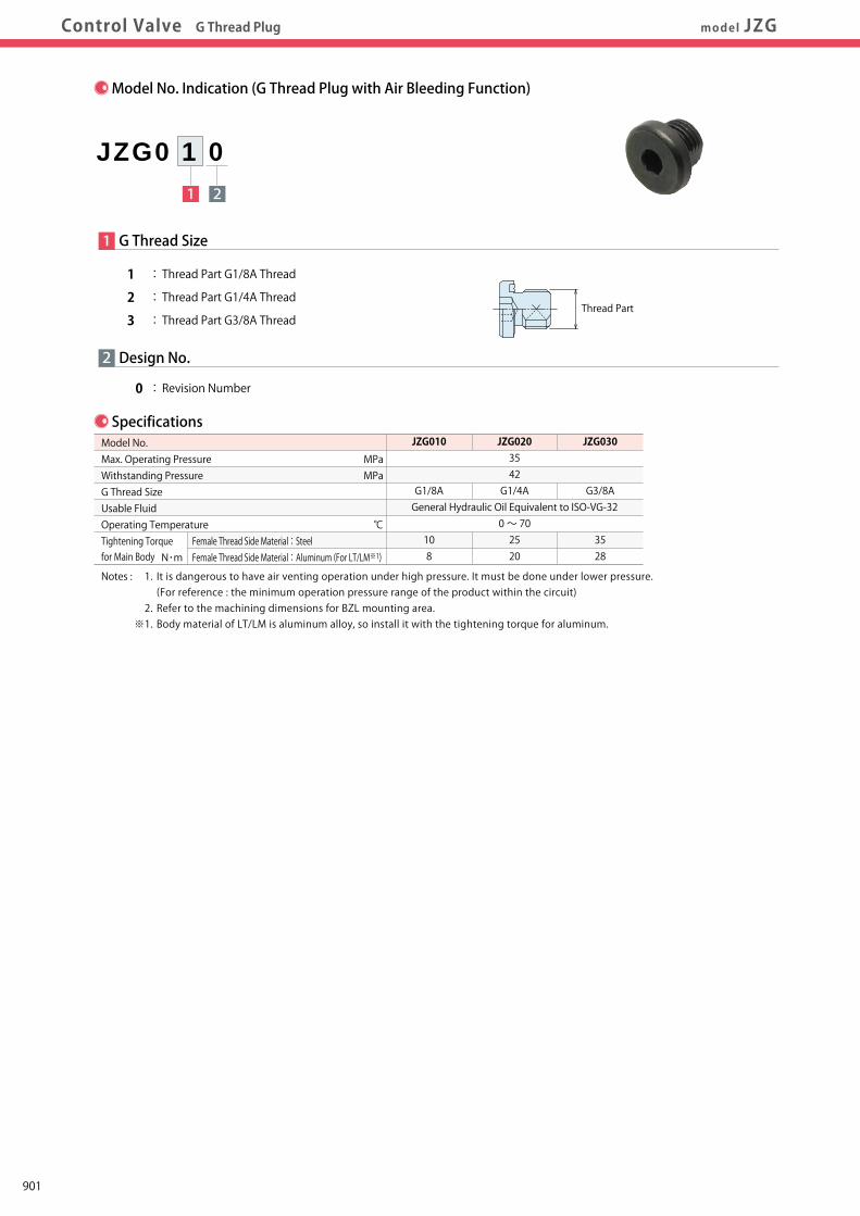
Work Support
LDLCTNCTC
Swing Clamp
LHA
Pneumatic Series
Hydraulic Series
Valve / CouplerHydraulic Unit
Cautions / Others
High-PowerSeries
Manual OperationAccessories
Hole Clamp
SFASFC
Link Clamp
LKALKCLKWLM/LJTMA-2TMA-1
Block Cylinder
DBADBC
Pallet Clamp
VSVT
Expansion Locating Pin
VFLVFMVFJVFK
FPFQ
Pull Stud Clamp
FVAFVDFVC
Centering Vise
DWA/DWB
CustomizedSpring Cylinder
LHCLHSLHWLT/LGTLA-2TLB-2TLA-1
LLW
Air SensingLift Cylinder
Compact Cylinder
LLLLRLLUDPDRDSDT
Control Valve
BZLBZTBZX/JZG
Control ValveDigest P.891 Model No. IndicationModel No. Indication SpecificationsSpecifications External DimensionsExternal DimensionsApplicable ProductsApplicable ProductsControl Valve G Thread Plug model JZG
Model No.ABCDG
JZG010 JZG020 JZG030 14 18 22 3.5 4.5 4.5 8 9 10 5 6 8 G1/8A G1/4A G3/8A
(mm)
CB
φA
Hex. Socket D
Exclusive Packing(Included)
G Thread
External Dimensions
Applicable Products
TLA-2 (Double Action)Swing ClampTLA0401-2C□-□TLA0601-2C□-□TLA0801-2C□-□TLA1001-2C□-□TLA1601-2C□-□TLA2001-2C□-□TLA2501-2C□-□TLA4001-2C□-□
Model No.
JZG010
JZG020
TLB-2 (Double Action)Swing ClampTLB0401-2C□-□TLB0601-2C□-□TLB0801-2C□-□TLB1001-2C□-□TLB1601-2C□-□TLB2001-2C□-□TLB2501-2C□-□TLB4001-2C□-□
TLA-1 (Single Action)Swing ClampTLA0402-1C□TLA0602-1C□TLA0802-1C□TLA1002-1C□TLA1602-1C□TLA2002-1C□TLA2502-1C□TLA4002-1C□
TMA-2 (Double Action)Link ClampTMA0250-2C□TMA0400-2C□TMA0600-2C□TMA1000-2C□
TMA1600-2C□TMA2500-2C□TMA3200-2C□
TMA-1 (Double Action)Link ClampTMA0250-1C□TMA0400-1C□TMA0600-1C□TMA1000-1C□
TMA1600-1C□TMA2500-1C□TMA3200-1C□
LKA (Double Action)Link ClampLKA0360-C□□-□LKA0400-C□□-□LKA0480-C□□-□LKA0550-C□□-□
LKA0650-C□□-□LKA0750-C□□-□LKA0900-C□□-□LKA1050-C□□-□
Model No.
JZG010
JZG020
JZG030
LKC (Double Action)Link ClampLKC0400-C□-□LKC0480-C□-□LKC0550-C□-□
LKC0650-C□-□
LKE (Double Action)High-Power Link ClampLKE0300-C□LKE0360-C□LKE0400-C□LKE0480-C□LKE0550-C□
LKW (Double Action)Link Clamp
LKW040□-C□□-□LKW048□-C□□-□LKW055□-C□□-□
LKW065□-C□□-□LKW0751-C□□-□
LM (Single Action)Link ClampLM0300-C□LM0360-C□LM0400-C□LM0480-C□LM0550-C□LM0650-C□LM0750-C□
LJ (Single Action)Link ClampLJ0302-C□LJ0362-C□LJ0402-C□LJ0482-C□LJ0552-C□LJ0652-C□LJ0752-C□LJ0902-C□LJ1052-C□
LLW (Double Action)Lift CylinderLLW036□-C□□-□LLW040□-C□□-□LLW048□-C□□-□
LC (Single Action)Work SupportLC0262-C□LC0302-C□LC0362-C□LC0402-C□□-□LC0482-C□□-□LC0552-C□□-□LC0652-C□□-□LC0752-C□□-□LC0902-C□□-□
Model No.
JZG010
JZG020
JZG030
LHA (Double Action)Swing ClampLHA0360-C□□-□LHA0400-C□□-□LHA0480-C□□-□LHA0550-C□□-□
LHA0650-C□□-□LHA0750-C□□-□LHA0900-C□□-□LHA1050-C□□-□
LHC (Double Action)Swing ClampLHC0360-C□□-□LHC0400-C□□-□LHC0480-C□□-□LHC0550-C□□-□
LHC0650-C□□-□
LHE (Double Action)High-Power Swing ClampLHE0300-C□LHE0360-C□LHE0400-C□LHE0480-C□LHE0550-C□
LHW (Double Action)Swing ClampLHW040□-C□□-□LHW048□-C□□-□LHW055□-C□□-□
LHW065□-C□□-□LHW0751-C□□-□
LHS (Double Action)Swing ClampLHS0360-C□□-□LHS0400-C□□-□LHS0480-C□□-□LHS0550-C□□-□
LHS0650-C□□-□LHS0750-C□□-□LHS0900-C□□-□LHS1050-C□□-□
DBA (Double Action)Block CylinderDBA0250-C□DBA0320-C□
DBA0400-C□DBA0500-C□
DBC (Double Action)Block CylinderDBC0250-C□DBC0320-C□
DBC0400-C□DBC0500-C□
Model No.
JZG010
JZG020
FVA (Double Action)Centering ViseFVA0401FVA0631FVA1001
FVC (Double Action)Centering ViseFVC0630
FVC1000FVC1600
FVD (Double Action)Centering ViseFVD1600FVD2500
FVD4000
LT (Single Action)Swing ClampLT0301-C□-□LT036□-C□-□LT040□-C□-□LT048□-C□-□LT055□-C□-□
LT065□-C□-□LT075□-C□-□
LG (Single Action)Swing ClampLG0301-C□-□LG036□-C□-□LG040□-C□-□LG048□-C□-□LG055□-C□-□
LG065□-C□-□LG075□-C□-□LG090□-C□-□LG105□-C□-□
LL (Double Action)Linear CylinderLL0360-C□□-□LL0400-C□□-□LL0480-C□□-□LL0550-C□□-□
LL0650-C□□-□LL0750-C□□-□LL0900-C□□-□LL1050-C□□-□
LLR (Double Action)Linear CylinderLLR0360-C□□-□-□LLR0400-C□□-□-□LLR0480-C□□-□-□LLR0550-C□□-□-□
LLR0650-C□□-□-□LLR0750-C□□-□-□LLR0900-C□□-□-□LLR1050-C□□-□-□
Model No. Indication (G Thread Plug with Air Bleeding Function)
1 2
JZG0 1 0
2
1 G Thread Size
1 : Thread Part G1/8A Thread
2 : Thread Part G1/4A Thread
3 : Thread Part G3/8A Thread
0 : Revision Number
Design No.
Thread Part
Specifications
MPaMPa
℃
N・m
JZG010
G1/8A
108
JZG0203542G1/4A
General Hydraulic Oil Equivalent to ISO-VG-320 ~ 702520
JZG030
G3/8A
3528
Model No.Max. Operating PressureWithstanding PressureG Thread SizeUsable FluidOperating Temperature Tightening Torquefor Main Body
Female Thread Side Material:SteelFemale Thread Side Material:Aluminum (For LT/LM※1)
Notes : 1. It is dangerous to have air venting operation under high pressure. It must be done under lower pressure. (For reference : the minimum operation pressure range of the product within the circuit) 2. Refer to the machining dimensions for BZL mounting area. ※1. Body material of LT/LM is aluminum alloy, so install it with the tightening torque for aluminum.
901
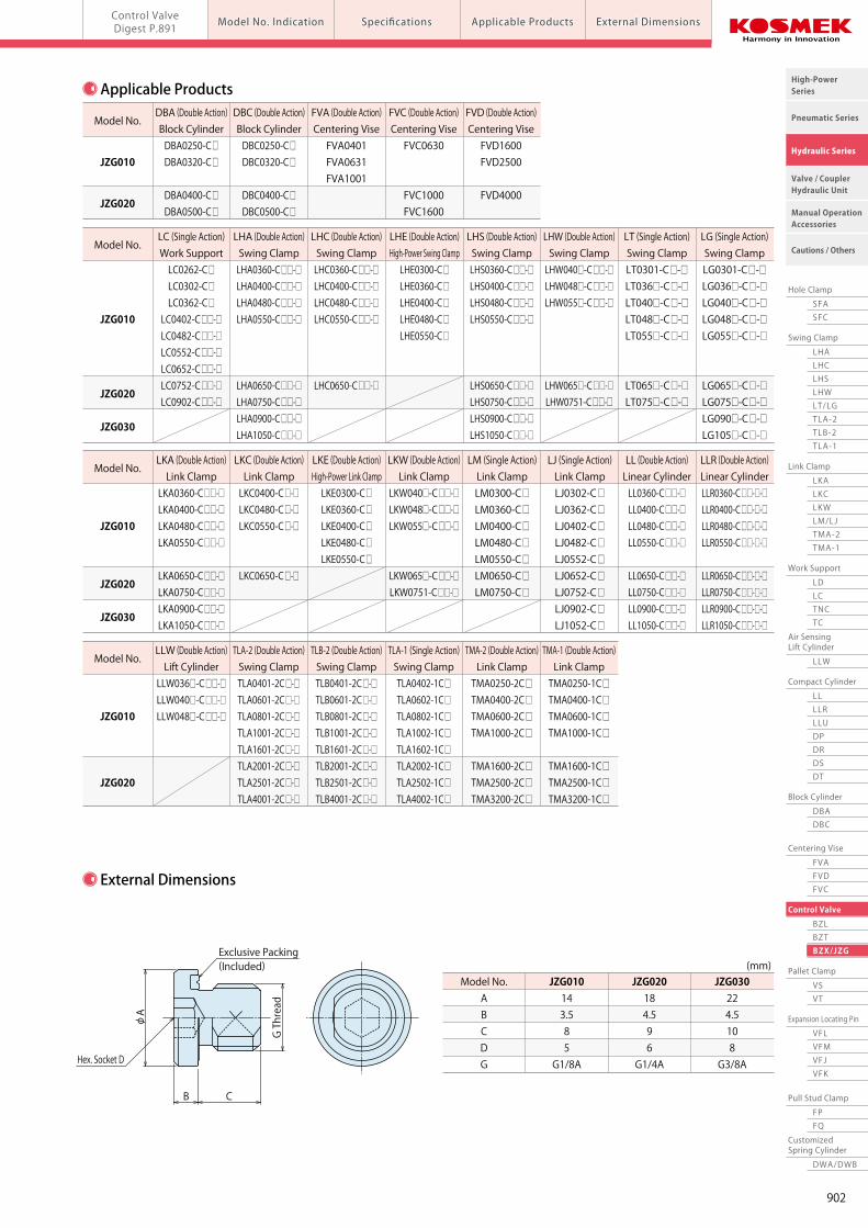
Work Support
LDLCTNCTC
Swing Clamp
LHA
Pneumatic Series
Hydraulic Series
Valve / CouplerHydraulic Unit
Cautions / Others
High-PowerSeries
Manual OperationAccessories
Hole Clamp
SFASFC
Link Clamp
LKALKCLKWLM/LJTMA-2TMA-1
Block Cylinder
DBADBC
Pallet Clamp
VSVT
Expansion Locating Pin
VFLVFMVFJVFK
FPFQ
Pull Stud Clamp
FVAFVDFVC
Centering Vise
DWA/DWB
CustomizedSpring Cylinder
LHCLHSLHWLT/LGTLA-2TLB-2TLA-1
LLW
Air SensingLift Cylinder
Compact Cylinder
LLLLRLLUDPDRDSDT
Control Valve
BZLBZTBZX/JZG
Control ValveDigest P.891 Model No. IndicationModel No. Indication SpecificationsSpecifications External DimensionsExternal DimensionsApplicable ProductsApplicable ProductsControl Valve G Thread Plug model JZG
Model No.ABCDG
JZG010 JZG020 JZG030 14 18 22 3.5 4.5 4.5 8 9 10 5 6 8 G1/8A G1/4A G3/8A
(mm)
CB
φA
Hex. Socket D
Exclusive Packing(Included)
G Thread
External Dimensions
Applicable Products
TLA-2 (Double Action)Swing ClampTLA0401-2C□-□TLA0601-2C□-□TLA0801-2C□-□TLA1001-2C□-□TLA1601-2C□-□TLA2001-2C□-□TLA2501-2C□-□TLA4001-2C□-□
Model No.
JZG010
JZG020
TLB-2 (Double Action)Swing ClampTLB0401-2C□-□TLB0601-2C□-□TLB0801-2C□-□TLB1001-2C□-□TLB1601-2C□-□TLB2001-2C□-□TLB2501-2C□-□TLB4001-2C□-□
TLA-1 (Single Action)Swing ClampTLA0402-1C□TLA0602-1C□TLA0802-1C□TLA1002-1C□TLA1602-1C□TLA2002-1C□TLA2502-1C□TLA4002-1C□
TMA-2 (Double Action)Link ClampTMA0250-2C□TMA0400-2C□TMA0600-2C□TMA1000-2C□
TMA1600-2C□TMA2500-2C□TMA3200-2C□
TMA-1 (Double Action)Link ClampTMA0250-1C□TMA0400-1C□TMA0600-1C□TMA1000-1C□
TMA1600-1C□TMA2500-1C□TMA3200-1C□
LKA (Double Action)Link ClampLKA0360-C□□-□LKA0400-C□□-□LKA0480-C□□-□LKA0550-C□□-□
LKA0650-C□□-□LKA0750-C□□-□LKA0900-C□□-□LKA1050-C□□-□
Model No.
JZG010
JZG020
JZG030
LKC (Double Action)Link ClampLKC0400-C□-□LKC0480-C□-□LKC0550-C□-□
LKC0650-C□-□
LKE (Double Action)High-Power Link ClampLKE0300-C□LKE0360-C□LKE0400-C□LKE0480-C□LKE0550-C□
LKW (Double Action)Link Clamp
LKW040□-C□□-□LKW048□-C□□-□LKW055□-C□□-□
LKW065□-C□□-□LKW0751-C□□-□
LM (Single Action)Link ClampLM0300-C□LM0360-C□LM0400-C□LM0480-C□LM0550-C□LM0650-C□LM0750-C□
LJ (Single Action)Link ClampLJ0302-C□LJ0362-C□LJ0402-C□LJ0482-C□LJ0552-C□LJ0652-C□LJ0752-C□LJ0902-C□LJ1052-C□
LLW (Double Action)Lift CylinderLLW036□-C□□-□LLW040□-C□□-□LLW048□-C□□-□
LC (Single Action)Work SupportLC0262-C□LC0302-C□LC0362-C□LC0402-C□□-□LC0482-C□□-□LC0552-C□□-□LC0652-C□□-□LC0752-C□□-□LC0902-C□□-□
Model No.
JZG010
JZG020
JZG030
LHA (Double Action)Swing ClampLHA0360-C□□-□LHA0400-C□□-□LHA0480-C□□-□LHA0550-C□□-□
LHA0650-C□□-□LHA0750-C□□-□LHA0900-C□□-□LHA1050-C□□-□
LHC (Double Action)Swing ClampLHC0360-C□□-□LHC0400-C□□-□LHC0480-C□□-□LHC0550-C□□-□
LHC0650-C□□-□
LHE (Double Action)High-Power Swing ClampLHE0300-C□LHE0360-C□LHE0400-C□LHE0480-C□LHE0550-C□
LHW (Double Action)Swing ClampLHW040□-C□□-□LHW048□-C□□-□LHW055□-C□□-□
LHW065□-C□□-□LHW0751-C□□-□
LHS (Double Action)Swing ClampLHS0360-C□□-□LHS0400-C□□-□LHS0480-C□□-□LHS0550-C□□-□
LHS0650-C□□-□LHS0750-C□□-□LHS0900-C□□-□LHS1050-C□□-□
DBA (Double Action)Block CylinderDBA0250-C□DBA0320-C□
DBA0400-C□DBA0500-C□
DBC (Double Action)Block CylinderDBC0250-C□DBC0320-C□
DBC0400-C□DBC0500-C□
Model No.
JZG010
JZG020
FVA (Double Action)Centering ViseFVA0401FVA0631FVA1001
FVC (Double Action)Centering ViseFVC0630
FVC1000FVC1600
FVD (Double Action)Centering ViseFVD1600FVD2500
FVD4000
LT (Single Action)Swing ClampLT0301-C□-□LT036□-C□-□LT040□-C□-□LT048□-C□-□LT055□-C□-□
LT065□-C□-□LT075□-C□-□
LG (Single Action)Swing ClampLG0301-C□-□LG036□-C□-□LG040□-C□-□LG048□-C□-□LG055□-C□-□
LG065□-C□-□LG075□-C□-□LG090□-C□-□LG105□-C□-□
LL (Double Action)Linear CylinderLL0360-C□□-□LL0400-C□□-□LL0480-C□□-□LL0550-C□□-□
LL0650-C□□-□LL0750-C□□-□LL0900-C□□-□LL1050-C□□-□
LLR (Double Action)Linear CylinderLLR0360-C□□-□-□LLR0400-C□□-□-□LLR0480-C□□-□-□LLR0550-C□□-□-□
LLR0650-C□□-□-□LLR0750-C□□-□-□LLR0900-C□□-□-□LLR1050-C□□-□-□
Model No. Indication (G Thread Plug with Air Bleeding Function)
1 2
JZG0 1 0
2
1 G Thread Size
1 : Thread Part G1/8A Thread
2 : Thread Part G1/4A Thread
3 : Thread Part G3/8A Thread
0 : Revision Number
Design No.
Thread Part
Specifications
MPaMPa
℃
N・m
JZG010
G1/8A
108
JZG0203542G1/4A
General Hydraulic Oil Equivalent to ISO-VG-320 ~ 702520
JZG030
G3/8A
3528
Model No.Max. Operating PressureWithstanding PressureG Thread SizeUsable FluidOperating Temperature Tightening Torquefor Main Body
Female Thread Side Material:SteelFemale Thread Side Material:Aluminum (For LT/LM※1)
Notes : 1. It is dangerous to have air venting operation under high pressure. It must be done under lower pressure. (For reference : the minimum operation pressure range of the product within the circuit) 2. Refer to the machining dimensions for BZL mounting area. ※1. Body material of LT/LM is aluminum alloy, so install it with the tightening torque for aluminum.
902
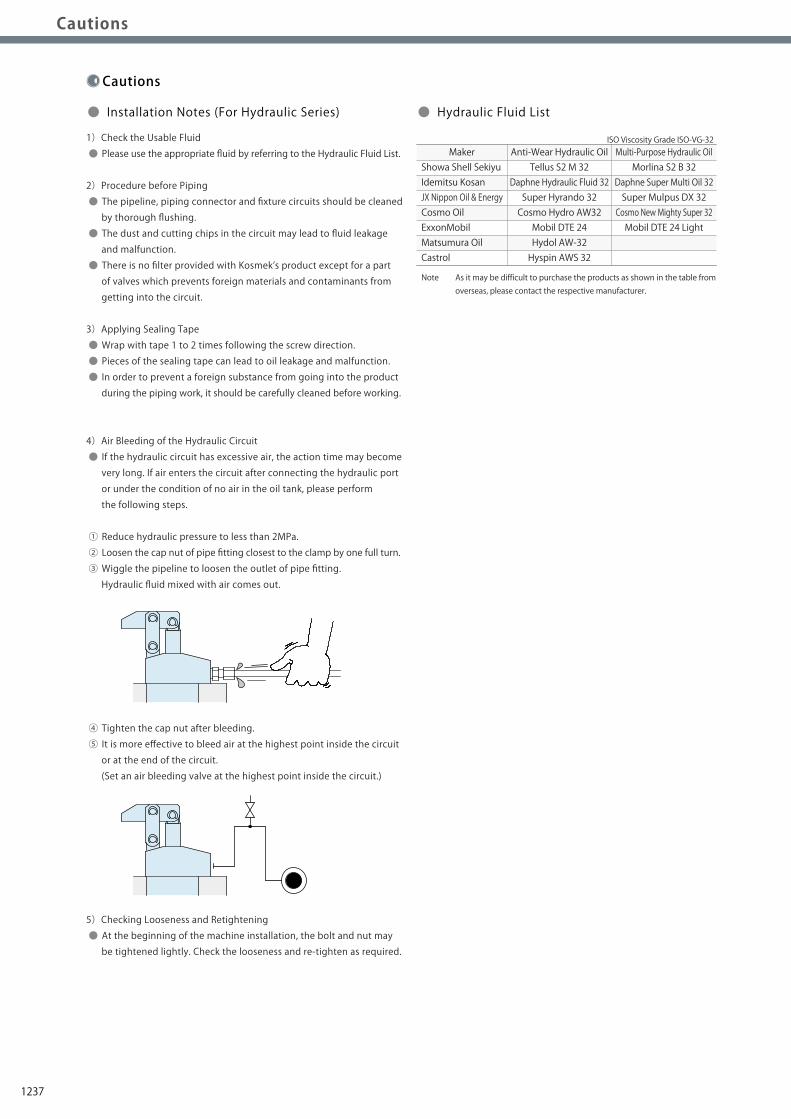
Notes on Hydraulic Cylinder Speed Control Circuit
Cautions
Installation Notes(For Hydraulic Series)
Hydraulic Fluid List
Notes on Handling
Maintenance/ Inspection
Warranty
Index
Search byAlphabetical Order
Company Profile
Sales Offices
Company Profile
Our Products
History
Pneumatic Series
Hydraulic Series
Valve / CouplerHydraulic Unit
Cautions / Others
High-PowerSeries
Manual OperationAccessories
Installation Notes(For Hydraulic Series)Installation Notes(For Hydraulic Series)
Notes on Hydraulic CylinderSpeed Control Circuit
Notes on Hydraulic CylinderSpeed Control Circuit Maintenance/Inspection WarrantyNotes on HandlingHydraulic Fluid ListHydraulic Fluid ListCautions
Cautions
● Installation Notes (For Hydraulic Series) ● Hydraulic Fluid List
1)Check the Usable Fluid
● Please use the appropriate fluid by referring to the Hydraulic Fluid List.
2)Procedure before Piping
● The pipeline, piping connector and fixture circuits should be cleaned
by thorough flushing.
● The dust and cutting chips in the circuit may lead to fluid leakage
and malfunction.
● There is no filter provided with Kosmek’s product except for a part
of valves which prevents foreign materials and contaminants from
getting into the circuit.
3)Applying Sealing Tape
● Wrap with tape 1 to 2 times following the screw direction.
● Pieces of the sealing tape can lead to oil leakage and malfunction.
● In order to prevent a foreign substance from going into the product
during the piping work, it should be carefully cleaned before working.
4)Air Bleeding of the Hydraulic Circuit
● If the hydraulic circuit has excessive air, the action time may become
very long. If air enters the circuit after connecting the hydraulic port
or under the condition of no air in the oil tank, please perform
the following steps.
① Reduce hydraulic pressure to less than 2MPa.
② Loosen the cap nut of pipe fitting closest to the clamp by one full turn.
③ Wiggle the pipeline to loosen the outlet of pipe fitting.
Hydraulic fluid mixed with air comes out.
④ Tighten the cap nut after bleeding.
⑤ It is more effective to bleed air at the highest point inside the circuit
or at the end of the circuit.
(Set an air bleeding valve at the highest point inside the circuit.)
5)Checking Looseness and Retightening
● At the beginning of the machine installation, the bolt and nut may
be tightened lightly. Check the looseness and re-tighten as required.
Showa Shell SekiyuIdemitsu KosanJX Nippon Oil & EnergyCosmo OilExxonMobilMatsumura OilCastrol
Maker Anti-Wear Hydraulic OilTellus S2 M 32
Daphne Hydraulic Fluid 32Super Hyrando 32Cosmo Hydro AW32Mobil DTE 24Hydol AW-32Hyspin AWS 32
Multi-Purpose Hydraulic OilMorlina S2 B 32
Daphne Super Multi Oil 32Super Mulpus DX 32Cosmo New Mighty Super 32Mobil DTE 24 Light
Note As it may be difficult to purchase the products as shown in the table from overseas, please contact the respective manufacturer.
ISO Viscosity Grade ISO-VG-32
Flow Control at the Release Side
W
Flow Control Valve(Any location is OK)
Sequence Valve
● Notes on Hydraulic Cylinder Speed Control Unit
Please pay attention to the cautions below. Design the hydraulic circuit for controlling the action speed of hydraulic cylinder.
Improper circuit design may lead to malfunctions and damages. Please review the circuit design in advance.! ● Flow Control Circuit for Single Acting Cylinder For spring return single acting cylinders, restricting flow during release can extremely slow down or disrupt release action. The preferred method is to control the flow during the lock action using a valve that has free-flow in the release direction. It is also preferred to provide a flow control valve at each actuator.
Accelerated clamping speed by excessive hydraulic flow to the cylinder may sustain damage. In this case add flow control to regulate flow. (Please add flow control to release flow if the lever weight is put on at the time of release action when using swing clamps.)
● Flow Control Circuit for Double Acting Cylinder Flow control circuit for double acting cylinder should have meter-out circuits for both the lock and release sides. Meter-in control can have adverse effect by presence of air in the system. However, in the case of controlling LKE, TMA, TLA, both lock side
and release side should be meter-in circuit.
Refer to P.75 for speed adjustment of LKE.
For TMA and TLA, if meter-out circuit is used, abnormal high
pressure is created, which causes oil leakage and damage.
【Meter-out Circuit】 (Except LKE/TMA/TLA)
【Meter-in Circuit】 (LKE/TMA/TLA must be controlled with meter-in.)
In the case of meter-out circuit, the hydraulic circuit should be designed with the following points. ① Single acting components should not be used in the same flow control circuit as the double acting components. The release action of the single acting cylinders may become erratic or very slow.
Refer to the following circuit when both the single acting cylinder and double acting cylinder are used together. ○ Separate the control circuit.
○ Reduce the influence of double acting cylinder control unit. However, due to the back pressure in tank line, single action cylinder is activated after double action cylinder works.
② In the case of meter-out circuit, the inner circuit pressure may increase during the cylinder action because of the fluid supply. The increase of the inner circuit pressure can be prevented by reducing the supplied fluid beforehand via the flow control valve. Especially when using sequence valve or pressure switches for clamping detection. If the back pressure is more than the set pressure then the system will not work as it is designed to.
1237
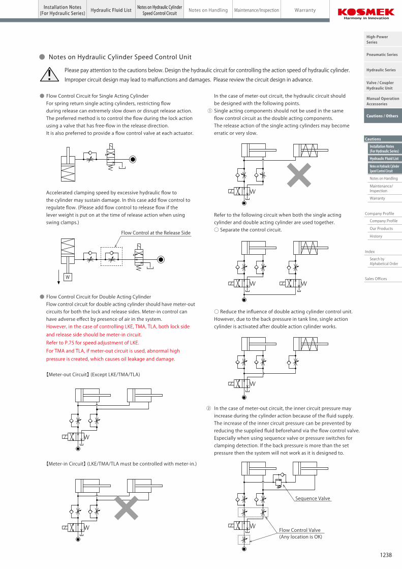
Notes on Hydraulic Cylinder Speed Control Circuit
Cautions
Installation Notes(For Hydraulic Series)
Hydraulic Fluid List
Notes on Handling
Maintenance/ Inspection
Warranty
Index
Search byAlphabetical Order
Company Profile
Sales Offices
Company Profile
Our Products
History
Pneumatic Series
Hydraulic Series
Valve / CouplerHydraulic Unit
Cautions / Others
High-PowerSeries
Manual OperationAccessories
Installation Notes(For Hydraulic Series)Installation Notes(For Hydraulic Series)
Notes on Hydraulic CylinderSpeed Control Circuit
Notes on Hydraulic CylinderSpeed Control Circuit Maintenance/Inspection WarrantyNotes on HandlingHydraulic Fluid ListHydraulic Fluid ListCautions
Cautions
● Installation Notes (For Hydraulic Series) ● Hydraulic Fluid List
1)Check the Usable Fluid
● Please use the appropriate fluid by referring to the Hydraulic Fluid List.
2)Procedure before Piping
● The pipeline, piping connector and fixture circuits should be cleaned
by thorough flushing.
● The dust and cutting chips in the circuit may lead to fluid leakage
and malfunction.
● There is no filter provided with Kosmek’s product except for a part
of valves which prevents foreign materials and contaminants from
getting into the circuit.
3)Applying Sealing Tape
● Wrap with tape 1 to 2 times following the screw direction.
● Pieces of the sealing tape can lead to oil leakage and malfunction.
● In order to prevent a foreign substance from going into the product
during the piping work, it should be carefully cleaned before working.
4)Air Bleeding of the Hydraulic Circuit
● If the hydraulic circuit has excessive air, the action time may become
very long. If air enters the circuit after connecting the hydraulic port
or under the condition of no air in the oil tank, please perform
the following steps.
① Reduce hydraulic pressure to less than 2MPa.
② Loosen the cap nut of pipe fitting closest to the clamp by one full turn.
③ Wiggle the pipeline to loosen the outlet of pipe fitting.
Hydraulic fluid mixed with air comes out.
④ Tighten the cap nut after bleeding.
⑤ It is more effective to bleed air at the highest point inside the circuit
or at the end of the circuit.
(Set an air bleeding valve at the highest point inside the circuit.)
5)Checking Looseness and Retightening
● At the beginning of the machine installation, the bolt and nut may
be tightened lightly. Check the looseness and re-tighten as required.
Showa Shell SekiyuIdemitsu KosanJX Nippon Oil & EnergyCosmo OilExxonMobilMatsumura OilCastrol
Maker Anti-Wear Hydraulic OilTellus S2 M 32
Daphne Hydraulic Fluid 32Super Hyrando 32Cosmo Hydro AW32Mobil DTE 24Hydol AW-32Hyspin AWS 32
Multi-Purpose Hydraulic OilMorlina S2 B 32
Daphne Super Multi Oil 32Super Mulpus DX 32Cosmo New Mighty Super 32Mobil DTE 24 Light
Note As it may be difficult to purchase the products as shown in the table from overseas, please contact the respective manufacturer.
ISO Viscosity Grade ISO-VG-32
Flow Control at the Release Side
W
Flow Control Valve(Any location is OK)
Sequence Valve
● Notes on Hydraulic Cylinder Speed Control Unit
Please pay attention to the cautions below. Design the hydraulic circuit for controlling the action speed of hydraulic cylinder.
Improper circuit design may lead to malfunctions and damages. Please review the circuit design in advance.! ● Flow Control Circuit for Single Acting Cylinder For spring return single acting cylinders, restricting flow during release can extremely slow down or disrupt release action. The preferred method is to control the flow during the lock action using a valve that has free-flow in the release direction. It is also preferred to provide a flow control valve at each actuator.
Accelerated clamping speed by excessive hydraulic flow to the cylinder may sustain damage. In this case add flow control to regulate flow. (Please add flow control to release flow if the lever weight is put on at the time of release action when using swing clamps.)
● Flow Control Circuit for Double Acting Cylinder Flow control circuit for double acting cylinder should have meter-out circuits for both the lock and release sides. Meter-in control can have adverse effect by presence of air in the system. However, in the case of controlling LKE, TMA, TLA, both lock side
and release side should be meter-in circuit.
Refer to P.75 for speed adjustment of LKE.
For TMA and TLA, if meter-out circuit is used, abnormal high
pressure is created, which causes oil leakage and damage.
【Meter-out Circuit】 (Except LKE/TMA/TLA)
【Meter-in Circuit】 (LKE/TMA/TLA must be controlled with meter-in.)
In the case of meter-out circuit, the hydraulic circuit should be designed with the following points. ① Single acting components should not be used in the same flow control circuit as the double acting components. The release action of the single acting cylinders may become erratic or very slow.
Refer to the following circuit when both the single acting cylinder and double acting cylinder are used together. ○ Separate the control circuit.
○ Reduce the influence of double acting cylinder control unit. However, due to the back pressure in tank line, single action cylinder is activated after double action cylinder works.
② In the case of meter-out circuit, the inner circuit pressure may increase during the cylinder action because of the fluid supply. The increase of the inner circuit pressure can be prevented by reducing the supplied fluid beforehand via the flow control valve. Especially when using sequence valve or pressure switches for clamping detection. If the back pressure is more than the set pressure then the system will not work as it is designed to.
1238
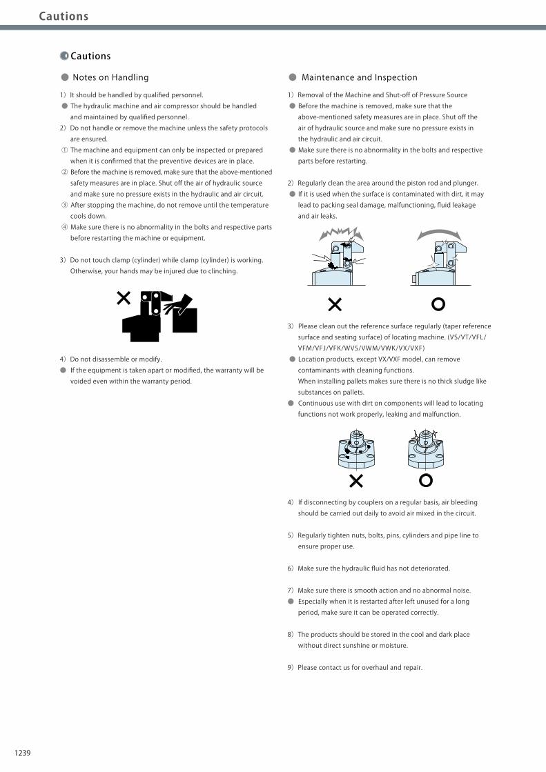
Notes on Hydraulic Cylinder Speed Control Circuit
Cautions
Installation Notes(For Hydraulic Series)
Hydraulic Fluid List
Notes on Handling
Maintenance/ Inspection
Warranty
Index
Search byAlphabetical Order
Company Profile
Sales Offices
Company Profile
Our Products
History
Pneumatic Series
Hydraulic Series
Valve / CouplerHydraulic Unit
Cautions / Others
High-PowerSeries
Manual OperationAccessories
Installation Notes(For Hydraulic Series)
Notes on Hydraulic CylinderSpeed Control Circuit Maintenance/InspectionMaintenance/Inspection WarrantyWarrantyNotes on HandlingNotes on HandlingHydraulic Fluid ListCautions
1)Warranty Period
● The product warranty period is 18 months from shipment from
our factory or 12 months from initial use, whichever is earlier.
2)Warranty Scope
● If the product is damaged or malfunctions during the warranty
period due to faulty design, materials or workmanship, we will
replace or repair the defective part at our expense.
Defects or failures caused by the following are not covered.
① If the stipulated maintenance and inspection are not carried out.
② If the product is used while it is not suitable for use based on
the operator’s judgment, resulting in defect.
③ If it is used or handled in inappropriate way by the operator.
(Including damage caused by the misconduct of the third party.)
④ If the defect is caused by reasons other than our responsibility.
⑤ If repair or modifications are carried out by anyone other than Kosmek,
or without our approval and confirmation, it will void warranty.
⑥ Other caused by natural disasters or calamities not attributable to
our company.
⑦ Parts or replacement expenses due to parts consumption and
deterioration.
(Such as rubber, plastic, seal material and some electric components.)
Damages excluding from direct result of a product defect shall be
excluded from the warranty.
● Warranty
Cautions
1)It should be handled by qualified personnel.
● The hydraulic machine and air compressor should be handled
and maintained by qualified personnel.
2)Do not handle or remove the machine unless the safety protocols
are ensured.
① The machine and equipment can only be inspected or prepared
when it is confirmed that the preventive devices are in place.
② Before the machine is removed, make sure that the above-mentioned
safety measures are in place. Shut off the air of hydraulic source
and make sure no pressure exists in the hydraulic and air circuit.
③ After stopping the machine, do not remove until the temperature
cools down.
④ Make sure there is no abnormality in the bolts and respective parts
before restarting the machine or equipment.
3)Do not touch clamp (cylinder) while clamp (cylinder) is working.
Otherwise, your hands may be injured due to clinching.
4)Do not disassemble or modify.
● If the equipment is taken apart or modified, the warranty will be
voided even within the warranty period.
1)Removal of the Machine and Shut-off of Pressure Source
● Before the machine is removed, make sure that the
above-mentioned safety measures are in place. Shut off the
air of hydraulic source and make sure no pressure exists in
the hydraulic and air circuit.
● Make sure there is no abnormality in the bolts and respective
parts before restarting.
2)Regularly clean the area around the piston rod and plunger.
● If it is used when the surface is contaminated with dirt, it may
lead to packing seal damage, malfunctioning, fluid leakage
and air leaks.
3) Please clean out the reference surface regularly (taper reference
surface and seating surface) of locating machine. (VS/VT/VFL/
VFM/VFJ/VFK/WVS/VWM/VWK/VX/VXF)
● Location products, except VX/VXF model, can remove
contaminants with cleaning functions.
When installing pallets makes sure there is no thick sludge like
substances on pallets.
● Continuous use with dirt on components will lead to locating
functions not work properly, leaking and malfunction.
4) If disconnecting by couplers on a regular basis, air bleeding
should be carried out daily to avoid air mixed in the circuit.
5)Regularly tighten nuts, bolts, pins, cylinders and pipe line to
ensure proper use.
6)Make sure the hydraulic fluid has not deteriorated.
7)Make sure there is smooth action and no abnormal noise.
● Especially when it is restarted after left unused for a long
period, make sure it can be operated correctly.
8)The products should be stored in the cool and dark place
without direct sunshine or moisture.
9)Please contact us for overhaul and repair.
● Notes on Handling ● Maintenance and Inspection
1239
Notes on Hydraulic Cylinder Speed Control Circuit
Cautions
Installation Notes(For Hydraulic Series)
Hydraulic Fluid List
Notes on Handling
Maintenance/ Inspection
Warranty
Index
Search byAlphabetical Order
Company Profile
Sales Offices
Company Profile
Our Products
History
Pneumatic Series
Hydraulic Series
Valve / CouplerHydraulic Unit
Cautions / Others
High-PowerSeries
Manual OperationAccessories
Installation Notes(For Hydraulic Series)
Notes on Hydraulic CylinderSpeed Control Circuit Maintenance/InspectionMaintenance/Inspection WarrantyWarrantyNotes on HandlingNotes on HandlingHydraulic Fluid ListCautions
1)Warranty Period
● The product warranty period is 18 months from shipment from
our factory or 12 months from initial use, whichever is earlier.
2)Warranty Scope
● If the product is damaged or malfunctions during the warranty
period due to faulty design, materials or workmanship, we will
replace or repair the defective part at our expense.
Defects or failures caused by the following are not covered.
① If the stipulated maintenance and inspection are not carried out.
② If the product is used while it is not suitable for use based on
the operator’s judgment, resulting in defect.
③ If it is used or handled in inappropriate way by the operator.
(Including damage caused by the misconduct of the third party.)
④ If the defect is caused by reasons other than our responsibility.
⑤ If repair or modifications are carried out by anyone other than Kosmek,
or without our approval and confirmation, it will void warranty.
⑥ Other caused by natural disasters or calamities not attributable to
our company.
⑦ Parts or replacement expenses due to parts consumption and
deterioration.
(Such as rubber, plastic, seal material and some electric components.)
Damages excluding from direct result of a product defect shall be
excluded from the warranty.
● Warranty
Cautions
1)It should be handled by qualified personnel.
● The hydraulic machine and air compressor should be handled
and maintained by qualified personnel.
2)Do not handle or remove the machine unless the safety protocols
are ensured.
① The machine and equipment can only be inspected or prepared
when it is confirmed that the preventive devices are in place.
② Before the machine is removed, make sure that the above-mentioned
safety measures are in place. Shut off the air of hydraulic source
and make sure no pressure exists in the hydraulic and air circuit.
③ After stopping the machine, do not remove until the temperature
cools down.
④ Make sure there is no abnormality in the bolts and respective parts
before restarting the machine or equipment.
3)Do not touch clamp (cylinder) while clamp (cylinder) is working.
Otherwise, your hands may be injured due to clinching.
4)Do not disassemble or modify.
● If the equipment is taken apart or modified, the warranty will be
voided even within the warranty period.
1)Removal of the Machine and Shut-off of Pressure Source
● Before the machine is removed, make sure that the
above-mentioned safety measures are in place. Shut off the
air of hydraulic source and make sure no pressure exists in
the hydraulic and air circuit.
● Make sure there is no abnormality in the bolts and respective
parts before restarting.
2)Regularly clean the area around the piston rod and plunger.
● If it is used when the surface is contaminated with dirt, it may
lead to packing seal damage, malfunctioning, fluid leakage
and air leaks.
3) Please clean out the reference surface regularly (taper reference
surface and seating surface) of locating machine. (VS/VT/VFL/
VFM/VFJ/VFK/WVS/VWM/VWK/VX/VXF)
● Location products, except VX/VXF model, can remove
contaminants with cleaning functions.
When installing pallets makes sure there is no thick sludge like
substances on pallets.
● Continuous use with dirt on components will lead to locating
functions not work properly, leaking and malfunction.
4) If disconnecting by couplers on a regular basis, air bleeding
should be carried out daily to avoid air mixed in the circuit.
5)Regularly tighten nuts, bolts, pins, cylinders and pipe line to
ensure proper use.
6)Make sure the hydraulic fluid has not deteriorated.
7)Make sure there is smooth action and no abnormal noise.
● Especially when it is restarted after left unused for a long
period, make sure it can be operated correctly.
8)The products should be stored in the cool and dark place
without direct sunshine or moisture.
9)Please contact us for overhaul and repair.
● Notes on Handling ● Maintenance and Inspection
1240
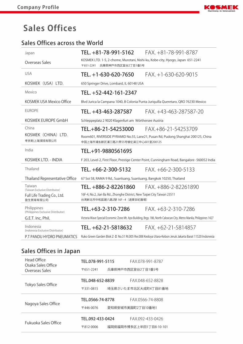
Company Profile
Overseas Affiliates and Sales OfficesDistributors
CanadaU.S.A.CanadaU.S.A.
EuropeEurope
Asia
BrazilBrazil
Asia
Australia
MexicoMexico
JapanChina
Taiwan
PhilippinesThailand
Japan
Korea
China
Taiwan
PhilippinesThailand
IndiaIndia
Korea
SingaporeSingaporeMalaysiaMalaysia
IndonesiaIndonesia
Global Network
Asia Detailed Map
● FOR FURTHER INFORMATION ON UNLISTED SPECIFICATIONS AND SIZES, PLEASE CALL US.● SPECIFICATIONS IN THIS CATALOG ARE SUBJECT TO CHANGE WITHOUT NOTICE.
JQA-QMA10823KOSMEK HEAD OFFICE
Sales Offices
TEL.078-991-5115 FAX.078-991-8787
Sales Offices in Japan
〒651-2241 兵庫県神戸市西区室谷2丁目1番5号
Tokyo Sales OfficeTEL.048-652-8839 FAX.048-652-8828
〒331-0815 埼玉県さいたま市北区大成町4丁目81番地
Nagoya Sales OfficeTEL.0566-74-8778 FAX.0566-74-8808
〒446-0076 愛知県安城市美園町2丁目10番地1
Fukuoka Sales OfficeTEL.092-433-0424 FAX.092-433-0426
〒812-0006 福岡県福岡市博多区上牟田1丁目8-10-101
Head OfficeOsaka Sales OfficeOverseas Sales
Japan
Overseas Sales
TEL. +81-78-991-5162 FAX. +81-78-991-8787
Sales Offices across the World
〒651-2241 兵庫県神戸市西区室谷2丁目1番5号
USA
KOSMEK(USA)LTD.
G.E.T. Inc, Phil.
TEL. +1-630-620-7650 FAX. +1-630-620-9015650 Springer Drive, Lombard, IL 60148 USA
EUROPE
KOSMEK EUROPE GmbH
TEL. +43-463-287587 FAX. +43-463-287587-20Schleppeplatz 2 9020 Klagenfurt am Wörthersee Austria
Thailand TEL. +66-2-300-5132 FAX. +66-2-300-5133 67 Soi 58, RAMA 9 Rd., Suanluang, Suanluang, Bangkok 10250, Thailand
Victoria Wave Special Economic Zone Mt. Apo Building, Brgy. 186, North Caloocan City, Metro Manila, Philippines 1427
China
考世美(上海)貿易有限公司
TEL.+86-21-54253000 FAX.+86-21-54253709
中国上海市浦东新区浦三路21弄55号银亿滨江中心601室200125
Taiwan
盈生貿易有限公司
Thailand Representative Office
Mexico TEL. +52-442-161-2347Blvd Jurica la Campana 1040, B Colonia Punta Juriquilla Queretaro, QRO 76230 MexicoKOSMEK USA Mexico Office
TEL. +886-2-82261860 FAX. +886-2-82261890
台湾新北市中和區建八路2號 16F-4(遠東世紀廣場)
Philippines TEL.+63-2-310-7286 FAX. +63-2-310-7286
P.T PANDU HYDRO PNEUMATICS Ruko Green Garden Blok Z-Ⅱ No.51 Rt.005 Rw.008 Kedoya Utara-Kebon Jeruk Jakarta Barat 11520 Indonesia
Indonesia TEL. +62-21-5818632 FAX. +62-21-5814857
16F-4, No.2, Jian Ba Rd., Zhonghe District, New Taipei City Taiwan 23511
Room601, RIVERSIDE PYRAMID No.55, Lane21, Pusan Rd, Pudong Shanghai 200125, China
KOSMEK LTD. 1-5, 2-chome, Murotani, Nishi-ku, Kobe-city, Hyogo, Japan 651-2241
KOSMEK(CHINA)LTD.
Full Life Trading Co., Ltd.
(Indonesia Exclusive Distributor)
(Philippines Exclusive Distributor)
(Taiwan Exclusive Distributor)
India
KOSMEK LTD. - INDIA
TEL.+91-9880561695F 203, Level-2, First Floor, Prestige Center Point, Cunningham Road, Bangalore -560052 India
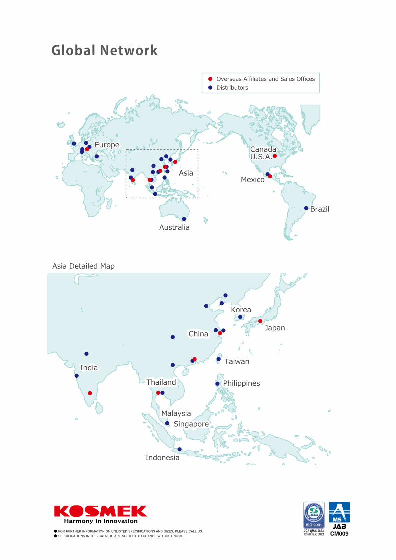
Related Documents


