IP VirtualWire Deployment Guide www.pluribusnetworks.com Technical Document

Welcome message from author
This document is posted to help you gain knowledge. Please leave a comment to let me know what you think about it! Share it to your friends and learn new things together.
Transcript
IP VirtualWire Deployment Guide
www.pluribusnetworks.com
Technical Document
Table of Contents
Pluribus Networks | IP VirtualWire Deployment Guide | 2 1 | Pluribus Networks | IP VirtualWire Deployment Guide
About This Document 2Step 1: Hardware Installation 2Step 2: Installing Netvisor ONE on Dell and Edgecore Switches 2 Obtaining the switch unique identifiers for Dell Switches 2 Obtaining the Switch Unique Identifiers for Edgecore Switches 3 Downloading the Netvisor ONE ONIE Image From Pluribus Networks Cloud 4 Activating a Switch from the Pluribus Networks Cloud 5 O�line installation of Netvisor ONE ONIE image and Switch Activation 6Step 3: Upgrading Netvisor ONE So�ware 9 Freedom Series Switches Upgrade 9 Fabric So�ware Upgrade 11 Step 4: Configuring the Adaptive Cloud Fabric and IP Underlay 12 1. Option A: configuring the Adaptive Cloud Fabric using an OOB management network 13 Configuring the switch ports 14 Configuring the IP Routing Underlay for An Out-of-Band Fabric 14 2. Option B: configuring the Adaptive Cloud Fabric using the In-Band network 18 Configuring the in-band IP of each switch for Fabric communication 18 Configure the Fabric on the Spine switches 24 Configure the Fabric on the Leaf switches 26 3. Errored and Runt Packet Transparency 28 4. IP VirtualWire Link State Tracking 29 5. IP VirtualWire Tracking Timeout Timer 29Step 5: Configuring the Overlay 30 Creating the VXLAN Tunnels on the Leaf Switches 30Step 6: Configure IP VirtualWire Connectivity 32 Configuring IP VirtualWire Using the CLI 32 Creating Intra-switch IP VirtualWire Connectivity 32 Deleting Intra-switch VirtualWire Connectivity 33 Creating Inter-switch VirtualWire Connectivity 33 Deleting Inter-switch VirtualWire Connectivity 35 Configuring IP VirtualWire Using UNUM 36 Modifying the Created IP VirtualWire Connection 38 Deleting the Created IP VirtualWire Connection 39 Configuring IP VirtualWire Using Quali Lab Automation So�ware 40
Pluribus Networks | IP VirtualWire Deployment Guide | 2
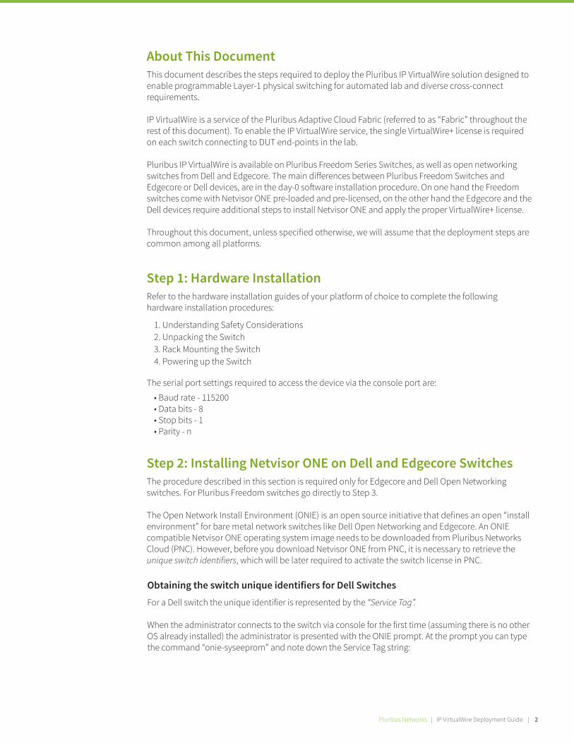
About This Document This document describes the steps required to deploy the Pluribus IP VirtualWire solution designed to enable programmable Layer-1 physical switching for automated lab and diverse cross-connect requirements.
IP VirtualWire is a service of the Pluribus Adaptive Cloud Fabric (referred to as “Fabric” throughout the rest of this document). To enable the IP VirtualWire service, the single VirtualWire+ license is required on each switch connecting to DUT end-points in the lab.
Pluribus IP VirtualWire is available on Pluribus Freedom Series Switches, as well as open networking switches from Dell and Edgecore. The main di�erences between Pluribus Freedom Switches and Edgecore or Dell devices, are in the day-0 so�ware installation procedure. On one hand the Freedom switches come with Netvisor ONE pre-loaded and pre-licensed, on the other hand the Edgecore and the Dell devices require additional steps to install Netvisor ONE and apply the proper VirtualWire+ license.
Throughout this document, unless specified otherwise, we will assume that the deployment steps are common among all platforms.
Step 1: Hardware Installation Refer to the hardware installation guides of your platform of choice to complete the following hardware installation procedures:
The serial port settings required to access the device via the console port are:
• Baud rate - 115200 • Data bits - 8 • Stop bits - 1 • Parity - n
1. Understanding Safety Considerations2. Unpacking the Switch3. Rack Mounting the Switch 4. Powering up the Switch
Figure 1: Building the unified Adaptive Cloud Fabric across multiple data centers over an agnostic IP-routed core.
Step 2: Installing Netvisor ONE on Dell and Edgecore Switches The procedure described in this section is required only for Edgecore and Dell Open Networking switches. For Pluribus Freedom switches go directly to Step 3.
The Open Network Install Environment (ONIE) is an open source initiative that defines an open “install environment” for bare metal network switches like Dell Open Networking and Edgecore. An ONIE compatible Netvisor ONE operating system image needs to be downloaded from Pluribus Networks Cloud (PNC). However, before you download Netvisor ONE from PNC, it is necessary to retrieve the unique switch identifiers, which will be later required to activate the switch license in PNC.
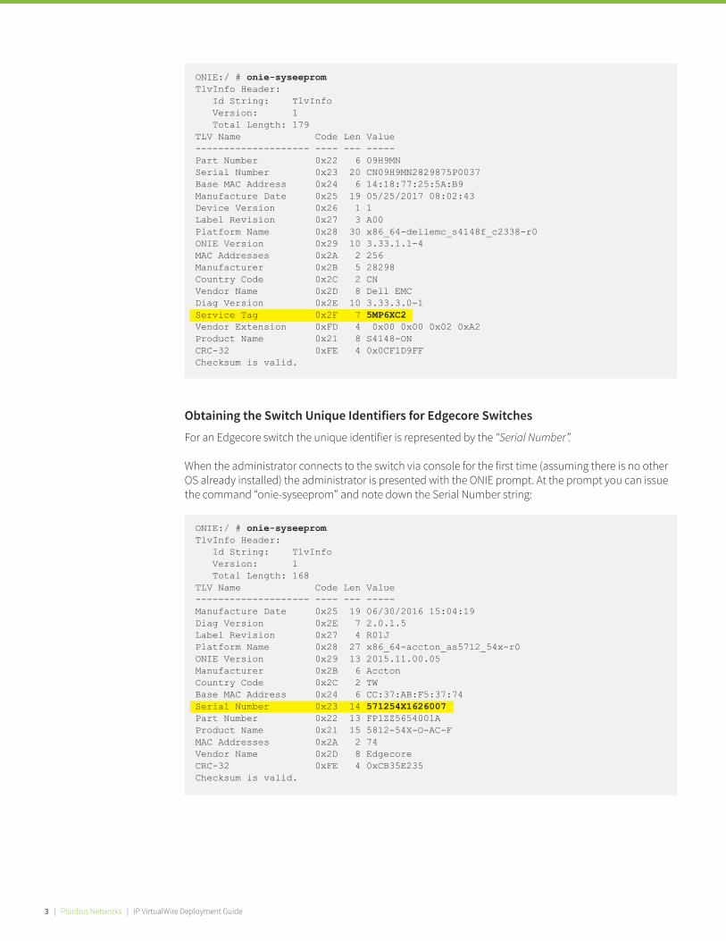
Obtaining the switch unique identifiers for Dell Switches
For a Dell switch the unique identifier is represented by the “Service Tag”.
When the administrator connects to the switch via console for the first time (assuming there is no other OS already installed) the administrator is presented with the ONIE prompt. At the prompt you can type the command “onie-syseeprom” and note down the Service Tag string:
3 | Pluribus Networks | IP VirtualWire Deployment Guide
ONIE:/ # onie-syseepromTlvInfo Header: Id String: TlvInfo Version: 1 Total Length: 179TLV Name Code Len Value-------------------- ---- --- -----Part Number 0x22 6 09H9MNSerial Number 0x23 20 CN09H9MN2829875P0037Base MAC Address 0x24 6 14:18:77:25:5A:B9Manufacture Date 0x25 19 05/25/2017 08:02:43Device Version 0x26 1 1Label Revision 0x27 3 A00Platform Name 0x28 30 x86_64-dellemc_s4148f_c2338-r0ONIE Version 0x29 10 3.33.1.1-4MAC Addresses 0x2A 2 256Manufacturer 0x2B 5 28298Country Code 0x2C 2 CNVendor Name 0x2D 8 Dell EMCDiag Version 0x2E 10 3.33.3.0-1Service Tag 0x2F 7 5MP6XC2Vendor Extension 0xFD 4 0x00 0x00 0x02 0xA2Product Name 0x21 8 S4148-ONCRC-32 0xFE 4 0x0CF1D9FFChecksum is valid.
Obtaining the Switch Unique Identifiers for Edgecore Switches
For an Edgecore switch the unique identifier is represented by the “Serial Number”.
When the administrator connects to the switch via console for the first time (assuming there is no other OS already installed) the administrator is presented with the ONIE prompt. At the prompt you can issue the command “onie-syseeprom” and note down the Serial Number string:
ONIE:/ # onie-syseepromTlvInfo Header: Id String: TlvInfo Version: 1 Total Length: 168TLV Name Code Len Value-------------------- ---- --- -----Manufacture Date 0x25 19 06/30/2016 15:04:19Diag Version 0x2E 7 2.0.1.5Label Revision 0x27 4 R01JPlatform Name 0x28 27 x86_64-accton_as5712_54x-r0ONIE Version 0x29 13 2015.11.00.05Manufacturer 0x2B 6 AcctonCountry Code 0x2C 2 TWBase MAC Address 0x24 6 CC:37:AB:F5:37:74Serial Number 0x23 14 571254X1626007Part Number 0x22 13 FP1ZZ5654001AProduct Name 0x21 15 5812-54X-O-AC-FMAC Addresses 0x2A 2 74Vendor Name 0x2D 8 EdgecoreCRC-32 0xFE 4 0xCB35E235Checksum is valid.
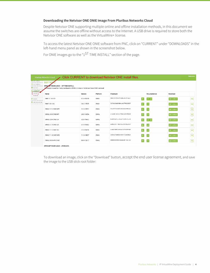
Figure 1: Building the unified Adaptive Cloud Fabric across multiple data centers over an agnostic IP-routed core.
Pluribus Networks | IP VirtualWire Deployment Guide | 4
To download an image, click on the “Download” button, accept the end user license agreement, and save the image to the USB stick root folder:
Downloading the Netvisor ONE ONIE Image From Pluribus Networks Cloud
Despite Netvisor ONE supporting multiple online and offline installation methods, in this document we assume the switches are offline without access to the Internet. A USB drive is required to store both the Netvisor ONE software as well as the VirtualWire+ license.
To access the latest Netvisor ONE ONIE software from PNC, click on “CURRENT” under “DOWNLOADS” in the left-hand menu panel as shown in the screenshot below.
For ONIE images go to the “1ST TIME INSTALL” section of the page.
5 | Pluribus Networks | IP VirtualWire Deployment Guide
Figure 2: High-level view of the DCI environment.
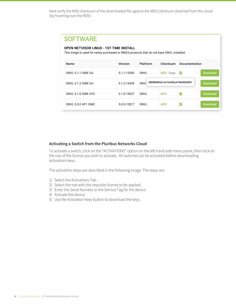
Next verify the MD5 checksum of the downloaded file against the MD5 checksum obtained from the cloud (by hovering over the MD5):
Activating a Switch from the Pluribus Networks Cloud
To activate a switch, click on the “ACTIVATIONS” option on the left-hand side menu panel, then click on the row of the license you wish to activate. All switches can be activated before downloading activations keys.
The activation steps are described in the following image. The steps are:
1) Select the Activations Tab.2) Select the row with the requisite license to be applied.3) Enter the Serial Number or the Service Tag for the device.4) Activate the device.5) Use the Activation Keys button to download the keys.

Pluribus Networks | IP VirtualWire Deployment Guide | 4 Pluribus Networks | IP VirtualWire Deployment Guide | 6
Then enter the “Service Tag” information, if you are activating a Dell switch, or the “Serial Number” if you are activating an Edgecore switch, and click on the “Activate” button:
Note that it is possible to activate multiple switches with a single “onvl-activation-keys” file as long as they use the same license type (e.g. ONVL-25G-PLEX-LIC or ONVL-100G-PLEX-LIC etc.). Note that at the time this document was written, a maximum of 20 switch activation keys can be downloaded per license.
After activating the switch, you should download the Activation Keys file and copy it to the same USB stick root folder where we placed the Netvisor ONE ONIE image.
To download the activation key(s) for the switch(es) activated using the same license type, click the button as illustrated in the picture below.
Offline installation of Netvisor ONE ONIE image and Switch Activation
Before you start, you need to make sure that:
First rename the Netvisor ONE ONIE image and Activation Keys file saved on the USB drive root folder:
• The switch cannot access the Internet (if necessary, disconnect the management port)• There is no previously installed Network OS on the switch
• Rename the file named “onie-installer-<version-number>” to “onie-installer” • Rename the Activation Keys file “onvl-activation-keys.dms” to “onvl-activation-keys”
7 | Pluribus Networks | IP VirtualWire Deployment Guide
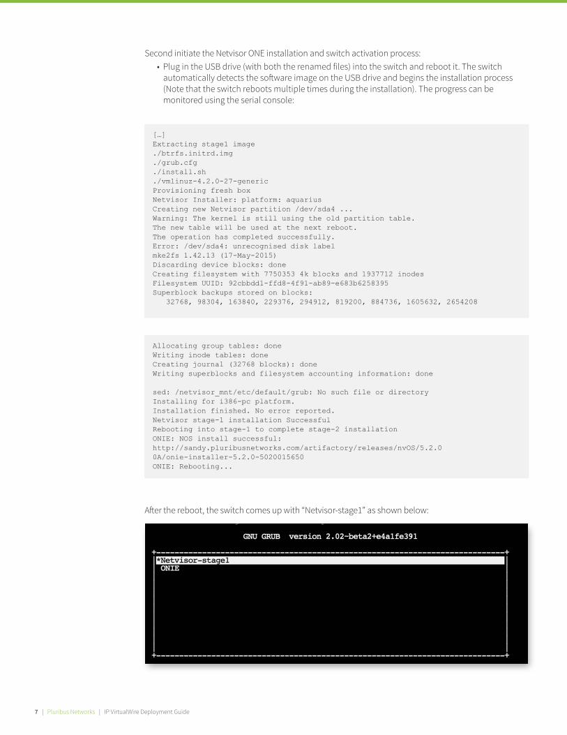
Second initiate the Netvisor ONE installation and switch activation process:
A�er the reboot, the switch comes up with “Netvisor-stage1” as shown below:
Plug in the USB drive (with both the renamed files) into the switch and reboot it. The switch automatically detects the so�ware image on the USB drive and begins the installation process (Note that the switch reboots multiple times during the installation). The progress can be monitored using the serial console:
•
[…]Extracting stage1 image./btrfs.initrd.img./grub.cfg./install.sh./vmlinuz-4.2.0-27-genericProvisioning fresh boxNetvisor Installer: platform: aquariusCreating new Netvisor partition /dev/sda4 ...Warning: The kernel is still using the old partition table.The new table will be used at the next reboot.The operation has completed successfully.Error: /dev/sda4: unrecognised disk labelmke2fs 1.42.13 (17-May-2015)Discarding device blocks: doneCreating filesystem with 7750353 4k blocks and 1937712 inodesFilesystem UUID: 92cbbdd1-ffd8-4f91-ab89-e683b6258395Superblock backups stored on blocks: 32768, 98304, 163840, 229376, 294912, 819200, 884736, 1605632, 2654208
Allocating group tables: doneWriting inode tables: doneCreating journal (32768 blocks): doneWriting superblocks and filesystem accounting information: done
sed: /netvisor_mnt/etc/default/grub: No such file or directoryInstalling for i386-pc platform.Installation finished. No error reported.Netvisor stage-1 installation SuccessfulRebooting into stage-1 to complete stage-2 installationONIE: NOS install successful: http://sandy.pluribusnetworks.com/artifactory/releases/nvOS/5.2.00A/onie-installer-5.2.0-5020015650ONIE: Rebooting...

Pluribus Networks | IP VirtualWire Deployment Guide | 8
At the completion of stage1, the switch prints the following messages and restarts one more time:
Next, the switch next boots into the “Netvisor-btrfs” mode in which the switch gets the license key from the USB drive and activates it at the end of this step.
[…]Setting up gettyGenerating GRUB config/init: line 393: can't create /netvisor-mnt/etc/mtab: nonexistent directorySetting up netvisor initial configInstalling GRUBmkdir: can't create directory '/netvisor-mnt/sys': File existsmkdir: can't create directory '/netvisor-mnt/dev': File existsmkdir: can't create directory '/netvisor-mnt/proc': File existsmount: mounting none on /netvisor-mnt/dev/pts failed: No such file or directoryInstalling for i386-pc platform.Installation finished. No error reported.Current default time zone: 'America/Los_Angeles'Local time is now: Sun Apr 19 15:33:23 PDT 2020.Universal Time is now: Sun Apr 19 22:33:23 UTC 2020.Updating initramfs ...update-initramfs: Generating /boot/initrd.img-4.15.0-36-genericResetting the grubenv fileNetvisor installation completedRebalancing Btrfs block tree[ 116.597985] BTRFS info (device sda4): relocating block group 6455033856 flags 5[ 116.617053] BTRFS info (device sda4): relocating block group 5381292032 flags 5[ 116.637495] BTRFS info (device sda4): relocating block group 4307550208 flags 5[ 116.655937] BTRFS info (device sda4): relocating block group 3233808384 flags 5[ 116.670648] BTRFS info (device sda4): relocating block group 2160066560 flags 5Done, had to relocate 5 out of 9 chunksDone, had to relocate 0 out of 4 chunksumount: can't umount /netvisor-mnt/dev/pts: No such file or directorymount: mounting UUID=92cbbdd1-ffd8-4f91-ab89-e68[ 117.656681] sd 4:0:0:0: [sda] Synchronizing SCSI cache3b6258395 on /netvisor_mnt failed: No such file [ 117.669433] reboot: Restarting system or directoryse[ 117.673993] reboot: machine restart
Once Netvisor is installed successfully, the “onvl-activation-keys” file in the USB is auto-detected and the switch is activated. At the end of the activation process the switch reboots one last time.
•

9 | Pluribus Networks | IP VirtualWire Deployment Guide
Pluribus Networks | IP VirtualWire Deployment Guide | 6
These messages are printed on console a�er a successful activation:
Once Netvisor ONE is installed and the switch is activated, wait for a minute until the login prompt appears and then log into the console using the following credentials:
The user is prompted to read and accept the EULA agreement and setup the switch parameters like switch name, management IP, password, DNS IP etc. Once those are configured, the user can SSH into the switches using the username “network-admin” and the user set password.
[…]AUTO-PROVISION: onvl-discover: onvl-activation-keys found: /dev/sdb1AUTO-PROVISION: Extracting initial bundle.AUTO-PROVISION: Decrypting signed bundle.AUTO-PROVISION: Extracting signed bundle.AUTO-PROVISION: Verifying package signature.AUTO-PROVISION: Extracting packages.AUTO-PROVISION: pkgs readyAUTO-PROVISION: onvl-installer: checking for device installer -8WWMX42/onvl-activation-keys...AUTO-PROVISION: onvl-installer: executing device installer - 8WWMX42/onvlactivation-keys...AUTO-PROVISION: [INSTALLED]Running Acceptance Tests...test passed commentTotal Memory: OK 7.78GSwitch device: OK orion found[GREEN] switch successfully initialized.serial number: 1550ST9100083hostid: 900011cdevice id: 8WWMX42Reboot required.
Username: network-adminPassword: admin
Step 3: Upgrading Netvisor ONE So�ware
Freedom Series Switches Upgrade A Pluribus Freedom switch always comes pre-loaded with the Netvisor ONE so�ware; however it is recommended to upgrade the Netvisor ONE so�ware to the latest release, which can be obtained from Pluribus Networks Cloud (PNC).
For a quick introduction on the services o�ered by PNC, please refer to this link (https://www.pluribusnetworks.com/get-started/) where you can find this short video: https://www.pluribusnetworks.com/resources/pluribus-networks-cloud-overview/.
To access the latest Netvisor ONE so�ware versions from PNC, click on “CURRENT” under “DOWNLOADS” in the le�-hand side menu panel. For upgrade images scroll down to the “OPEN NETVISOR LINUX - UPGRADES” section of the page.

Pluribus Networks | IP VirtualWire Deployment Guide | 10
To download an image, click on the “Download” button:
Next verify the MD5 checksum of the downloaded file against the MD5 value posted onthe cloud (by hovering over the MD5 label, as shown above).
A�er the image is downloaded apply the following procedure to upgrade the so�ware on the Freedom switch:
• Enable SFTP from the CLI using the command:
(admin@netvisor) > admin-sftp-modify enablesftp password:confirm sftp password:
• Go to the shell from the CLI by typing the command “shell” and going to the “s�p” folder:
(admin@Spine) > shelladmin@netvisor:~$ cd /sftp/import/
(admin@Spine) > software-upgrade package <upgrade-image-name>
• Enable the shell access for the network-admin user using the command:
• To exit the shell, type “exit” so that the prompt goes back to the cli• Copy the file to the “/s�p/import” folder on the switch• To upgrade the image, run the command:
(admin@netvisor) > role-modify name network-admin shell
• The status of the upgrade process can be checked using the command:
The switch reboots a�er the upgrade and comes back up with the new image.
(admin@Spine) > software-upgrade-status-show
• The license on the switch can be verified using the command:
(admin@Spine) > software-license-show

11 | Pluribus Networks | IP VirtualWire Deployment Guide
To enable shell access to copy the file to the folder, use the command:
The switches can then be rebooted together using the command fabric-upgrade-finish. Or they can be manually rebooted one at a time using the switch-reboot command on each switch.
Instead, if the auto-finish option was selected, then all the switches automatically reboot a�er the installation.
You can choose how to finish the upgrade process: all the nodes of the fabric can be rebooted at once a�er successfully upgrading using the keyword auto-finish, which will reboot all the nodes of the fabric at once. Alternatively, you can choose to manually reboot each node of the fabric (for example within a scheduled downtime window) using the keyword manual-reboot, as shown below.
admin@netvisor) > admin-sftp-modify enablesftp password:confirm sftp password:
(admin@netvisor) > shellnetwork-admin@netvisor:~$ cd /sftp/importnetwork-admin@netvisor:/sftp/import$
(admin@netvisor) > fabric-upgrade-start packages nvOS-5.2.1-5020115676-onvl.pkg manual-rebootWarning: This will start software upgrade on your entire fabric.Please confirm y/n (Default: n):
(admin@netvisor) > role-modify name network-admin shell
fabric-upgrade-start packages nvOS-<version>-onvl.pkg <manual-reboot>/<auto-finish>
To access the shell:
Scheduled background update.Use:* fabric-upgrade-status-show to check progress* fabric-upgrade-finish to finalize when complete* fabric-upgrade-abort to cancel cleanly* switch-reboot on each switch in fabric to reboot manually after finish
Confirm the upgrade by pressing “y” at this prompt. You will see the following message:
Fabric So�ware Upgrade Pluribus Netvisor ONE provides a command for the user to upgrade all the nodes of the fabric at the same time instead of having to upgrade them individually.
The fabric-upgrade process works on all switches running Pluribus Netvisor (Freedom series, Dell and Edgecore). For the fabric-upgrade to work, all the switches should be part of the fabric.
This fabric-wide upgrade process requires the desired image to be copied to at least one of the nodes. Then the rest of the process can take place even when not connected to the Internet.
To copy the upgrade image to a switch, enable the SFTP service using the following command and then enter a password of your choice:
Copy the upgrade file into the /s�p/import folder of any node of the fabric. The file can be copied to the /s�p/import directory:
• from a server, using wget or scp• from a USB key
Before starting the upgrade process, make sure that all the nodes of the fabric are online: you can use the command fabric-node-show and check that state is online for all the nodes.
Once the file is successfully copied to the specified folder of the node, use the command fabric-upgrade- start to initiate the fabric-wide upgrade process.
Pluribus Networks | IP VirtualWire Deployment Guide | 12
The current status of the upgrade can be displayed using the fabric-upgrade-status-show command. In addition, this command can be used in conjunction with the show-interval * command to periodically check the upgrade status (for example, you can use fabric-upgrade-status-show show-interval 5 to check the status every 5 seconds).
During a fabric-wide upgrade, these are the messages produced by the fabric-upgrade-status-show command, based on the current progress status:
A�er the fabric-upgrade-status-show progress message becomes Waiting for fabric-upgrade-finish/ abort for all the fabric nodes, you can manually reboot each node of the fabric and the switches will come back up running the upgraded version of Netvisor ONE.
Note that all the nodes of the fabric need to be running the same so�ware version for the features to work properly.
During the installation, if there is any issue, the upgrade process can be rolled back using the command fabric-upgrade-abort. A�er issuing this command, the upgrade process on all the nodes is stopped and the switches are reset to run their older version of Netvisor ONE.
Also, configuration changes cannot be done while the fabric—upgrade is in process or once the upgrade is finishd and awaiting reboot to come up with the new version. The user needs to make sure to schedule the upgrade when no configuration changes are to be done.
The upgrade package is downloaded from the initial node to all the other nodes
Once successfully downloaded, the o�line bundle is extracted
The signature of the package is verified
The packages are extracted and readied to install
The nodes wait for the package to be extracted on all nodes of the fabric
The switch upgrades Netvisor from the older version to the newer one
The switches wait for the user to complete the upgrade once it completes using either of the commands mentioned above
Downloading package bundle
Extracting initial bundle
Extracting signed bundle
Extracting packages
Agent needs restart
Upgrading nvOS *
Waiting for fabric-upgrade-finish/abort
Message Description
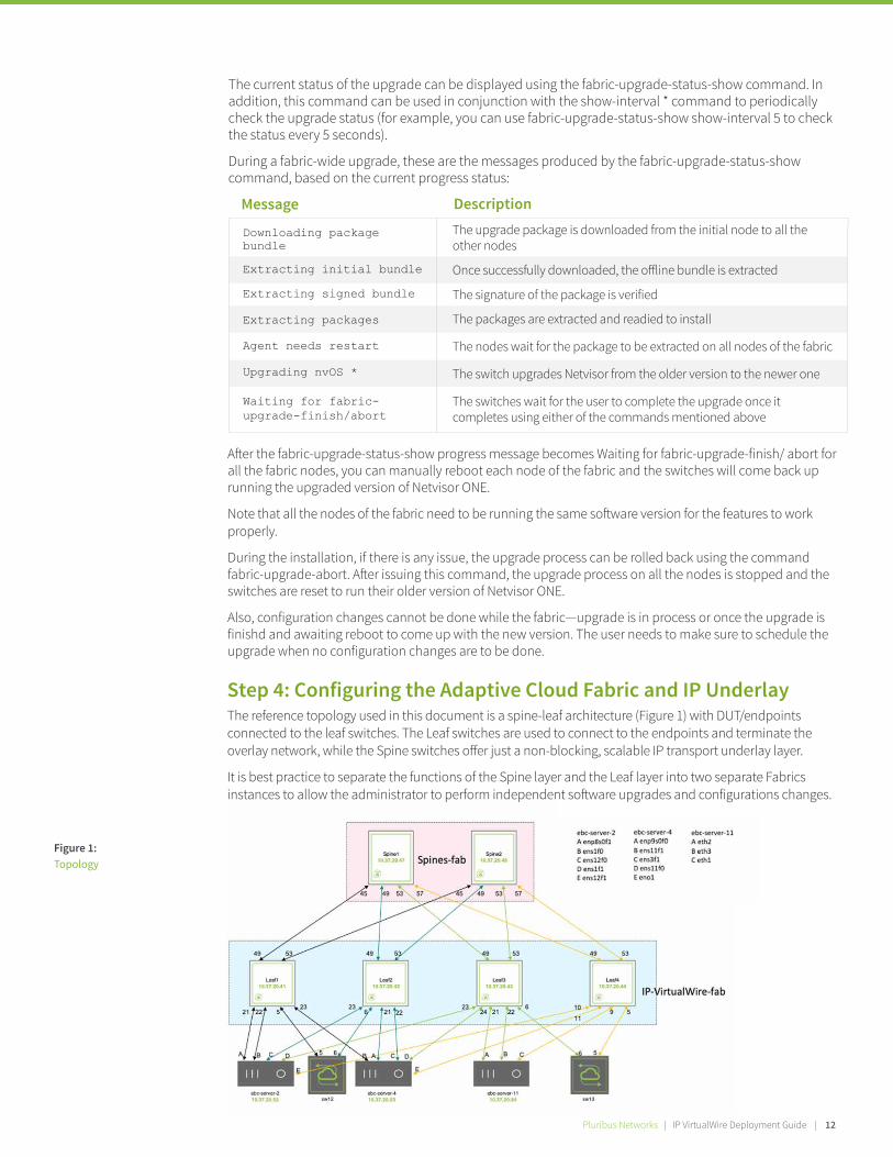
Figure 1: Topology
Step 4: Configuring the Adaptive Cloud Fabric and IP Underlay The reference topology used in this document is a spine-leaf architecture (Figure 1) with DUT/endpoints connected to the leaf switches. The Leaf switches are used to connect to the endpoints and terminate the overlay network, while the Spine switches o�er just a non-blocking, scalable IP transport underlay layer.
It is best practice to separate the functions of the Spine layer and the Leaf layer into two separate Fabrics instances to allow the administrator to perform independent so�ware upgrades and configurations changes.
13 | Pluribus Networks | IP VirtualWire Deployment Guide
The Fabric can be configured to have its control plane communication to run on an out-of-band management network or in-band using the same front panel ports carrying the IP VirtualWire tra�ic.
The out-of-band Fabric communication method is simpler and recommended for Fabrics in a single site or POD.
The in-band Fabric communication method is required when the Fabric is created across multiple geo-distributed locations separated by a routed network. We’ll review an example of In-band Fabric configuration in section 2. This should serve as a reference for multi-site configurations.
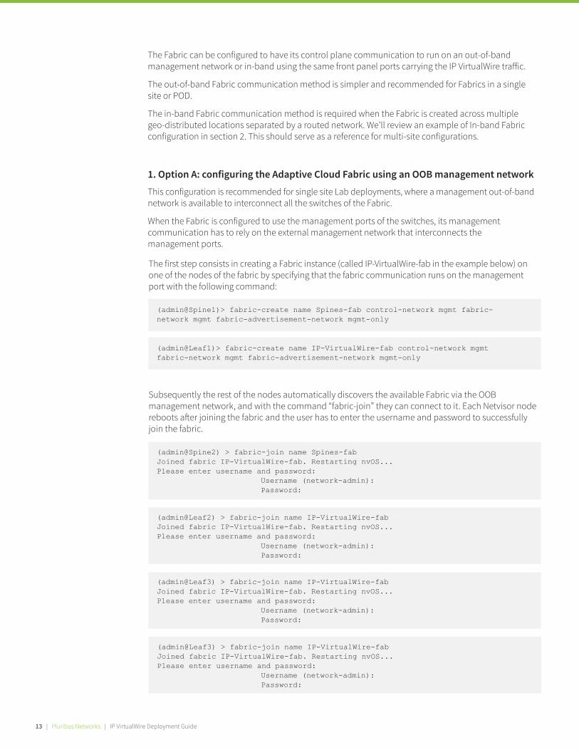
1. Option A: configuring the Adaptive Cloud Fabric using an OOB management networkThis configuration is recommended for single site Lab deployments, where a management out-of-band network is available to interconnect all the switches of the Fabric.
When the Fabric is configured to use the management ports of the switches, its management communication has to rely on the external management network that interconnects the management ports.
The first step consists in creating a Fabric instance (called IP-VirtualWire-fab in the example below) on one of the nodes of the fabric by specifying that the fabric communication runs on the management port with the following command:
(admin@Spine1)> fabric-create name Spines-fab control-network mgmt fabric-network mgmt fabric-advertisement-network mgmt-only
(admin@Spine2) > fabric-join name Spines-fabJoined fabric IP-VirtualWire-fab. Restarting nvOS...Please enter username and password:
Username (network-admin):Password:
(admin@Leaf2) > fabric-join name IP-VirtualWire-fabJoined fabric IP-VirtualWire-fab. Restarting nvOS...Please enter username and password:
Username (network-admin):Password:
(admin@Leaf3) > fabric-join name IP-VirtualWire-fabJoined fabric IP-VirtualWire-fab. Restarting nvOS...Please enter username and password:
Username (network-admin):Password:
(admin@Leaf1)> fabric-create name IP-VirtualWire-fab control-network mgmt fabric-network mgmt fabric-advertisement-network mgmt-only
Subsequently the rest of the nodes automatically discovers the available Fabric via the OOB management network, and with the command “fabric-join” they can connect to it. Each Netvisor node reboots a�er joining the fabric and the user has to enter the username and password to successfully join the fabric.
(admin@Leaf3) > fabric-join name IP-VirtualWire-fabJoined fabric IP-VirtualWire-fab. Restarting nvOS...Please enter username and password:
Username (network-admin):Password:

Pluribus Networks | IP VirtualWire Deployment Guide | 14
(admin@Spine1) > port-config-modify port 45 speed 40g description to_Leaf1 jumbo enable(admin@Spine1) > port-config-modify port 49 speed 40g description to_Leaf2 jumbo enable(admin@Spine1) > port-config-modify port 53 speed 40g description to_Leaf3 jumbo enable(admin@Spine1) > port-config-modify port 57 speed 40g description to_Leaf4 jumbo enable
The status of the Fabric can be checked using the “fabric-node-show” command. If all the nodes are exchanging Fabric information, their “state” is “online”.
Configuring the switch ports Before we dive into the IP Underlay configuration, we proceed to configure the port attributes of each connection and dd a description to the link on each switch for the topology shown in Figure 1.
On Spine1:
(admin@Spine2) > port-config-modify port 45 speed 40g description to_Leaf1 jumbo enable(admin@Spine2) > port-config-modify port 49 speed 40g description to_Leaf2 jumbo enable(admin@Spine2) > port-config-modify port 53 speed 40g description to_Leaf3 jumbo enable(admin@Spine2) > port-config-modify port 57 speed 40g description to_Leaf4 jumbo enable
On Spine2:
(admin@Leaf1) > port-config-modify port 49 description to_Spine1 jumbo speed 40g enable(admin@Leaf1) > port-config-modify port 53 description to_Spine2 jumbo speed 40g enable(admin@Leaf1) > port-config-modify port 5 speed 10g jumbo description to_sw12_p5 enable(admin@Leaf1) > port-config-modify port 21 speed 1g jumbo description to_srvr2_enp8s0f1 enable(admin@Leaf1) > port-config-modify port 22 speed 10g jumbo description to_srvr2_ens1f0 enable(admin@Leaf1) > port-config-modify port 23 speed 10g jumbo description to_srvr4_ens11f1 enable
On Leaf1:
(admin@Leaf2) > port-config-modify port 49 description to_Spine1 jumbo speed 40g enable(admin@Leaf2) > port-config-modify port 53 description to_Spine2 jumbo speed 40g enable(admin@Leaf2) > port-config-modify port 6 speed 10g jumbo description to_sw12_p6 enable(admin@Leaf2) > port-config-modify port 21 speed 1g jumbo description to_srvr4_enp9s0f0 enable(admin@Leaf2) > port-config-modify port 22 speed 10g jumbo description to_srvr4_ens3f1 enable(admin@Leaf2) > port-config-modify port 23 speed 10g jumbo description to_srvr2_ens12f0 enable
On Leaf2:
(admin@Leaf3) > port-config-modify port 49 description to_Spine1 jumbo speed 40g enable(admin@Leaf3) > port-config-modify port 53 description to_Spine2 jumbo speed 40g enable(admin@Leaf3) > port-config-modify port 6 speed 10g jumbo description to_sw13_p6 enable(admin@Leaf3) > port-config-modify port 21 speed 1g jumbo description to_srvr11_eth2 enable(admin@Leaf3) > port-config-modify port 22 speed 10g jumbo description to_srvr11_eth3 enable(admin@Leaf3) > port-config-modify port 23 speed 10g jumbo description to_srvr2_ens1f1 enable(admin@Leaf3) > port-config-modify port 24 speed 10g jumbo description to_srvr4_ens11f0 enable
On Leaf3:
(admin@Leaf4) > port-config-modify port 49 description to_Spine1 jumbo speed 40g enable(admin@Leaf4) > port-config-modify port 53 description to_Spine2 jumbo speed 40g enable(admin@Leaf4) > port-config-modify port 5 speed 10g jumbo description to_sw13_p5 enable(admin@Leaf4) > port-config-modify port 9 speed 10g jumbo description to_srvr11_eth1 enable(admin@Leaf4) > port-config-modify port 10 speed 10g jumbo description to_srvr2_ens12f1 enable(admin@Leaf4) > port-config-modify port 11 speed 10g jumbo description to_srvr4_eno1 enable
On Leaf4:
Configuring the IP Routing Underlay for An Out-of-Band Fabric A�er creating the out-of-band fabric and configuring the switch ports, the next step consists in creating the IP Underlay network between the leaf and the spine layers. This IP routed network represents the underlay transport for the IP VirtualWire overlay service. Building the IP underlay is a day-0 operation.
The IP underlay can be configured using standard networking protocols. For the purpose of this documentation we will configure the underlay using BGP.

(admin@Spine1) > vrouter-create name Spine1-vr vnet IP-VirtualWire-fab-global router-id 1.0.0.1 bgp-as 65001 proto-multi none bgp-redistribute connected, static, bgp-max-paths 16 bgp-bestpath-as-path multipath-relax,Creating Spine1-vr zone, please wait...vrouter created (pim supported on 31 interfaces only)
We start by creating a vRouter, on each of the switches, with an associated BGP AS number:
On Spine1:
(admin@Spine2) > vrouter-create name Spine2-vr vnet IP-VirtualWire-fab-global router-id 1.0.0.2 bgp-as 65002 proto-multi none bgp-redistribute connected, static, bgp-max-paths 16 bgp-bestpath-as-path multipath-relax,Creating Spine2-vr zone, please wait...vrouter created (pim supported on 31 interfaces only)
On Spine2:
(admin@Leaf1) > vrouter-create name Leaf1-vr vnet IP-VirtualWire-fab-global router-id 1.0.0.3 bgp-as 65003 proto-multi none bgp-redistribute connected, static, bgp-max-paths 16 bgp-bestpath-as-path multipath-relax,Creating Leaf1-vr zone, please wait...vrouter created (pim supported on 31 interfaces only)
On Leaf1:
(admin@Leaf2) > vrouter-create name Leaf2-vr vnet IP-VirtualWire-fab-global router-id 1.0.0.4 bgp-as 65004 proto-multi none bgp-redistribute connected, static, bgp-max-paths 16 bgp-bestpath-as-path multipath-relax,Creating Leaf2-vr zone, please wait...vrouter created (pim supported on 31 interfaces only)
On Leaf2:
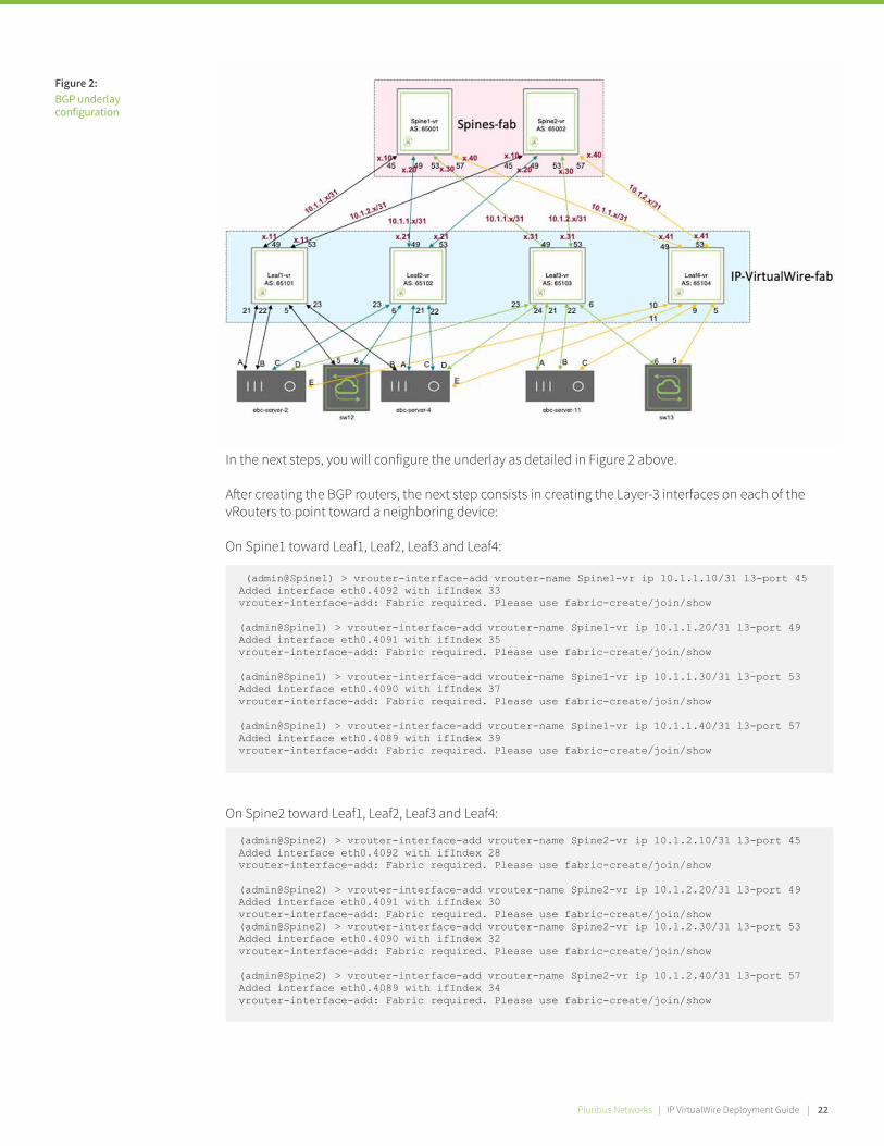
Figure 2: BGP underlay configuration
15 | Pluribus Networks | IP VirtualWire Deployment Guide
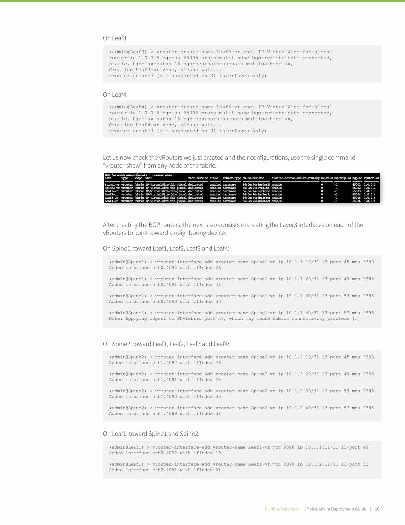
Let us now check the vRouters we just created and their configurations, use the single command “vrouter-show” from any node of the fabric:
A�er creating the BGP routers, the next step consists in creating the Layer3 interfaces on each of the vRouters to point toward a neighboring device:
On Leaf3:
(admin@Leaf3) > vrouter-create name Leaf3-vr vnet IP-VirtualWire-fab-global router-id 1.0.0.5 bgp-as 65005 proto-multi none bgp-redistribute connected, static, bgp-max-paths 16 bgp-bestpath-as-path multipath-relax,Creating Leaf3-vr zone, please wait...vrouter created (pim supported on 31 interfaces only)
On Spine1, toward Leaf1, Leaf2, Leaf3 and Leaf4:
(admin@Spine1) > vrouter-interface-add vrouter-name Spine1-vr ip 10.1.1.10/31 l3-port 45 mtu 9398Added interface eth0.4092 with ifIndex 26
(admin@Spine1) > vrouter-interface-add vrouter-name Spine1-vr ip 10.1.1.20/31 l3-port 49 mtu 9398Added interface eth0.4091 with ifIndex 28
(admin@Spine1) > vrouter-interface-add vrouter-name Spine1-vr ip 10.1.1.30/31 l3-port 53 mtu 9398Added interface eth0.4090 with ifIndex 30
(admin@Spine1) > vrouter-interface-add vrouter-name Spine1-vr ip 10.1.1.40/31 l3-port 57 mtu 9398Note: Applying l3port to PN-fabric port 57, which may cause fabric connectivity problems […]
On Spine2, toward Leaf1, Leaf2, Leaf3 and Leaf4:
(admin@Spine2) > vrouter-interface-add vrouter-name Spine2-vr ip 10.1.2.10/31 l3-port 45 mtu 9398Added interface eth1.4092 with ifIndex 26
(admin@Spine2) > vrouter-interface-add vrouter-name Spine2-vr ip 10.1.2.20/31 l3-port 49 mtu 9398Added interface eth1.4091 with ifIndex 28
(admin@Spine2) > vrouter-interface-add vrouter-name Spine2-vr ip 10.1.2.30/31 l3-port 53 mtu 9398Added interface eth1.4090 with ifIndex 30
(admin@Spine2) > vrouter-interface-add vrouter-name Spine2-vr ip 10.1.2.40/31 l3-port 57 mtu 9398Added interface eth1.4089 with ifIndex 32
On Leaf1, toward Spine1 and Spine2:
(admin@Leaf1) > vrouter-interface-add vrouter-name Leaf1-vr mtu 9398 ip 10.1.1.11/31 l3-port 49Added interface eth2.4092 with ifIndex 19
(admin@Leaf1) > vrouter-interface-add vrouter-name Leaf1-vr mtu 9398 ip 10.1.2.11/31 l3-port 53Added interface eth2.4091 with ifIndex 21
On Leaf4:
(admin@Leaf4) > vrouter-create name Leaf4-vr vnet IP-VirtualWire-fab-global router-id 1.0.0.6 bgp-as 65006 proto-multi none bgp-redistribute connected, static, bgp-max-paths 16 bgp-bestpath-as-path multipath-relax,Creating Leaf4-vr zone, please wait...vrouter created (pim supported on 31 interfaces only)
Pluribus Networks | IP VirtualWire Deployment Guide | 16

On Leaf2, toward Spine1 and Spine2:
(admin@Leaf2) > vrouter-interface-add vrouter-name Leaf2-vr mtu 9398 ip 10.1.1.21/31 l3-port 49Added interface eth6.4092 with ifIndex 25
(admin@Leaf2) > vrouter-interface-add vrouter-name Leaf2-vr mtu 9398 ip 10.1.2.21/31 l3-port 53Added interface eth4.4091 with ifIndex 27
On Leaf3, toward Spine1 and Spine2:
(admin@Leaf3) > vrouter-interface-add vrouter-name Leaf3-vr mtu 9398 ip 10.1.1.31/31 l3-port 49Added interface eth8.4092 with ifIndex 23
(admin@Leaf3) > vrouter-interface-add vrouter-name Leaf3-vr mtu 9398 ip 10.1.2.31/31 l3-port 53Added interface eth7.4091 with ifIndex 25
On Leaf4, toward Spine1 and Spine2:
We can now check that the interfaces created on each vRouter are active by using a single command “vrouter-interface-show” for the entire fabric and verify that “nic-state” is “up”:
At this point we are ready to configure the BGP neighbors on each vRouter.
(admin@Leaf4) > vrouter-interface-add vrouter-name Leaf4-vr mtu 9398 ip 10.1.1.41/31 l3-port 49Added interface eth7.4092 with ifIndex 26
(admin@Leaf4) > vrouter-interface-add vrouter-name Leaf4-vr mtu 9398 ip 10.1.2.41/31 l3-port 53Added interface eth6.4091 with ifIndex 28
On the Spine1 vRouter:
(admin@Spine1) > vrouter-bgp-add vrouter-name Spine1-vr neighbor 10.1.1.11 remote-as 65003(admin@Spine1) > vrouter-bgp-add vrouter-name Spine1-vr neighbor 10.1.1.21 remote-as 65004(admin@Spine1) > vrouter-bgp-add vrouter-name Spine1-vr neighbor 10.1.1.31 remote-as 65005(admin@Spine1) > vrouter-bgp-add vrouter-name Spine1-vr neighbor 10.1.1.41 remote-as 65006
On the Spine2 vRouter:
(admin@Spine2) > vrouter-bgp-add vrouter-name Spine2-vr neighbor 10.1.2.11 remote-as 65003(admin@Spine2) > vrouter-bgp-add vrouter-name Spine2-vr neighbor 10.1.2.21 remote-as 65004(admin@Spine2) > vrouter-bgp-add vrouter-name Spine2-vr neighbor 10.1.2.31 remote-as 65005(admin@Spine2) > vrouter-bgp-add vrouter-name Spine2-vr neighbor 10.1.2.41 remote-as 65006
17 | Pluribus Networks | IP VirtualWire Deployment Guide
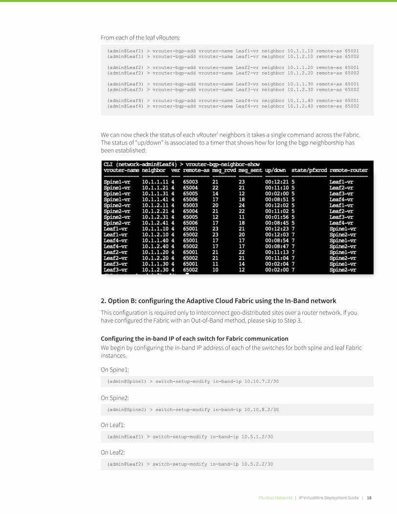
We can now check the status of each vRouter’ neighbors it takes a single command across the Fabric. The status of “up/down” is associated to a timer that shows how for long the bgp neighborship has been established:
From each of the leaf vRouters:
(admin@Leaf1) > vrouter-bgp-add vrouter-name Leaf1-vr neighbor 10.1.1.10 remote-as 65001(admin@Leaf1) > vrouter-bgp-add vrouter-name Leaf1-vr neighbor 10.1.2.10 remote-as 65002
(admin@Leaf2) > vrouter-bgp-add vrouter-name Leaf2-vr neighbor 10.1.1.20 remote-as 65001(admin@Leaf2) > vrouter-bgp-add vrouter-name Leaf2-vr neighbor 10.1.2.20 remote-as 65002
(admin@Leaf3) > vrouter-bgp-add vrouter-name Leaf3-vr neighbor 10.1.1.30 remote-as 65001(admin@Leaf3) > vrouter-bgp-add vrouter-name Leaf3-vr neighbor 10.1.2.30 remote-as 65002
(admin@Leaf4) > vrouter-bgp-add vrouter-name Leaf4-vr neighbor 10.1.1.40 remote-as 65001(admin@Leaf4) > vrouter-bgp-add vrouter-name Leaf4-vr neighbor 10.1.2.40 remote-as 65002
On Spine1:
(admin@Spine1) > switch-setup-modify in-band-ip 10.10.7.2/30
On Spine2:
(admin@Spine2) > switch-setup-modify in-band-ip 10.10.8.2/30
On Leaf1:
(admin@Leaf1) > switch-setup-modify in-band-ip 10.5.1.2/30
On Leaf2:
(admin@Leaf2) > switch-setup-modify in-band-ip 10.5.2.2/30
2. Option B: configuring the Adaptive Cloud Fabric using the In-Band networkThis configuration is required only to interconnect geo-distributed sites over a router network. If you have configured the Fabric with an Out-of-Band method, please skip to Step 3.
Configuring the in-band IP of each switch for Fabric communication We begin by configuring the in-band IP address of each of the switches for both spine and leaf Fabric instances.
Pluribus Networks | IP VirtualWire Deployment Guide | 16 Pluribus Networks | IP VirtualWire Deployment Guide | 18

On Leaf3:
(admin@Leaf3) > switch-setup-modify in-band-ip 10.5.3.2/30
On Spine1:
(admin@Spine1) > vrouter-create name Spine1-vr fabric-comm router-id 10.10.1.1 bgp-as 65001 bgp-bestpath-as-path multipath-relax, bgp-redistribute connected, bgp-max-paths 16Creating Spine1-vr zone, please wait...vrouter createdvrouter-create: Fabric required. Please use fabric-create/join/show
On Spine2:
(admin@Spine2) > vrouter-create name Spine2-vr fabric-comm router-id 10.10.2.2 bgp-as 65002 bgp-bestpath-as-path multipath-relax, bgp-redistribute connected, bgp-max-paths 16Creating Spine2-vr zone, please wait...vrouter createdvrouter-create: Fabric required. Please use fabric-create/join/show
On Leaf1:
(admin@Leaf1) > vrouter-create name Leaf1-vr fabric-comm router-id 10.20.1.1 bgp-as 65101 bgp-bestpath-as-path multipath-relax, bgp-redistribute connected, bgp-max-paths 16Creating Leaf1-vr zone, please wait...vrouter createdvrouter-create: Fabric required. Please use fabric-create/join/show
On Leaf2:
(admin@Leaf2) > vrouter-create name Leaf2-vr fabric-comm router-id 10.20.2.2 bgp-as 65102 bgp-bestpath-as-path multipath-relax, bgp-redistribute connected, bgp-max-paths 16Creating Leaf2-vr zone, please wait...vrouter createdvrouter-create: Fabric required. Please use fabric-create/join/show
On Leaf3:
(admin@Leaf3) > vrouter-create name Leaf3-vr fabric-comm router-id 10.20.3.3 bgp-as 65103 bgp-bestpath-as-path multipath-relax, bgp-redistribute connected, bgp-max-paths 16Creating Leaf3-vr zone, please wait...vrouter createdvrouter-create: Fabric required. Please use fabric-create/join/show
On Leaf4:
(admin@Leaf4) > switch-setup-modify in-band-ip 10.5.4.2/30
Configuring vRouters and In-Band IP Interfaces on Each Switch for Fabric CommunicationCreate a vRouter on each of the spine and leaf switches using the keyword “fabric-comm” to denote that this vRouter is used by interfaces for fabric-communication. Associate each of these vRouters to a BGP AS number.
(Note: Most of the commands display a message “Fabric required” until the node is part of a fabric, these messages can be ignored)
19 | Pluribus Networks | IP VirtualWire Deployment Guide

On Leaf4:
(admin@Leaf4) > vrouter-create name Leaf4-vr fabric-comm router-id 10.20.4.4 bgp-as 65104 bgp-bestpath-as-path multipath-relax, bgp-redistribute connected, bgp-max-paths 16Creating Leaf4-vr zone, please wait...vrouter createdvrouter-create: Fabric required. Please use fabric-create/join/show
On Spine1:
(admin@Spine1) > vrouter-interface-add vrouter-name Spine1-vr vlan 1 ip 10.10.7.1/30Added interface eth0.1 with ifIndex 31vrouter-interface-add: Fabric required. Please use fabric-create/join/show
On Spine2:
(admin@Spine2) > vrouter-interface-add vrouter-name Spine2-vr vlan 1 ip 10.10.8.1/30Added interface eth0.1 with ifIndex 26vrouter-interface-add: Fabric required. Please use fabric-create/join/show
On Leaf1:
(admin@Leaf1) > vrouter-interface-add vrouter-name Leaf1-vr vlan 1 ip 10.5.1.1/30Added interface eth0.1 with ifIndex 19vrouter-interface-add: Fabric required. Please use fabric-create/join/show
On Leaf2:
(admin@Leaf2) > vrouter-interface-add vrouter-name Leaf2-vr vlan 1 ip 10.5.2.1/30Added interface eth0.1 with ifIndex 19vrouter-interface-add: Fabric required. Please use fabric-create/join/show
On Leaf3:
(admin@Leaf3) > vrouter-interface-add vrouter-name Leaf3-vr vlan 1 ip 10.5.3.1/30Added interface eth0.1 with ifIndex 19vrouter-interface-add: Fabric required. Please use fabric-create/join/show
On Leaf4:
(admin@Leaf4) > vrouter-interface-add vrouter-name Leaf4-vr vlan 1 ip 10.5.4.1/30Added interface eth0.1 with ifIndex 16vrouter-interface-add: Fabric required. Please use fabric-create/join/show
Then, on each of the switches create a vRouter interface that is in the same IP network as the in-band address.
To enable the fabric communication and the reachability among the Virtual Tunnel End Points (VTEPs) of the leaf switches, the next step consists in the configuration of an is to IP underlay network that provides fabric-wide Layer-3 connectivity.
The underlay can be configured using standard networking protocols (Netvisor ONE supports both L2 and L3 standard protocols). As long as all the nodes of the fabric can communicate with each other, end-to-end connections between endpoints can be established.
O�entimes the preferred underlay configuration uses a dynamic routing protocol such as BGP or OSPF or, in simpler cases, just static routes. For the purpose of this documentation we will configure the underlay using BGP.
Pluribus Networks | IP VirtualWire Deployment Guide | 18 Pluribus Networks | IP VirtualWire Deployment Guide | 20
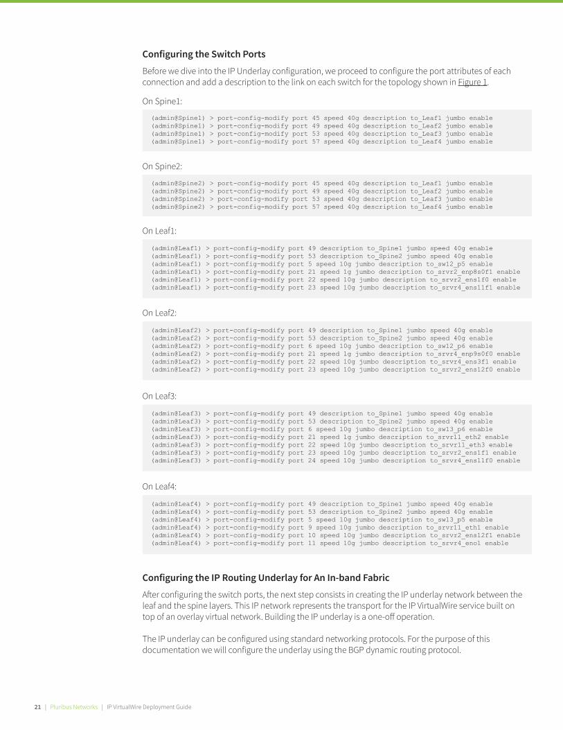
Configuring the Switch Ports Before we dive into the IP Underlay configuration, we proceed to configure the port attributes of each connection and add a description to the link on each switch for the topology shown in Figure 1.
Configuring the IP Routing Underlay for An In-band Fabric A�er configuring the switch ports, the next step consists in creating the IP underlay network between the leaf and the spine layers. This IP network represents the transport for the IP VirtualWire service built on top of an overlay virtual network. Building the IP underlay is a one-o� operation.
The IP underlay can be configured using standard networking protocols. For the purpose of thisdocumentation we will configure the underlay using the BGP dynamic routing protocol.
On Spine1:
(admin@Spine1) > port-config-modify port 45 speed 40g description to_Leaf1 jumbo enable(admin@Spine1) > port-config-modify port 49 speed 40g description to_Leaf2 jumbo enable(admin@Spine1) > port-config-modify port 53 speed 40g description to_Leaf3 jumbo enable(admin@Spine1) > port-config-modify port 57 speed 40g description to_Leaf4 jumbo enable
On Spine2:
(admin@Spine2) > port-config-modify port 45 speed 40g description to_Leaf1 jumbo enable(admin@Spine2) > port-config-modify port 49 speed 40g description to_Leaf2 jumbo enable(admin@Spine2) > port-config-modify port 53 speed 40g description to_Leaf3 jumbo enable(admin@Spine2) > port-config-modify port 57 speed 40g description to_Leaf4 jumbo enable
On Leaf1:
(admin@Leaf1) > port-config-modify port 49 description to_Spine1 jumbo speed 40g enable(admin@Leaf1) > port-config-modify port 53 description to_Spine2 jumbo speed 40g enable(admin@Leaf1) > port-config-modify port 5 speed 10g jumbo description to_sw12_p5 enable(admin@Leaf1) > port-config-modify port 21 speed 1g jumbo description to_srvr2_enp8s0f1 enable(admin@Leaf1) > port-config-modify port 22 speed 10g jumbo description to_srvr2_ens1f0 enable(admin@Leaf1) > port-config-modify port 23 speed 10g jumbo description to_srvr4_ens11f1 enable
On Leaf2:
(admin@Leaf2) > port-config-modify port 49 description to_Spine1 jumbo speed 40g enable(admin@Leaf2) > port-config-modify port 53 description to_Spine2 jumbo speed 40g enable(admin@Leaf2) > port-config-modify port 6 speed 10g jumbo description to_sw12_p6 enable(admin@Leaf2) > port-config-modify port 21 speed 1g jumbo description to_srvr4_enp9s0f0 enable(admin@Leaf2) > port-config-modify port 22 speed 10g jumbo description to_srvr4_ens3f1 enable(admin@Leaf2) > port-config-modify port 23 speed 10g jumbo description to_srvr2_ens12f0 enable
On Leaf3:
(admin@Leaf3) > port-config-modify port 49 description to_Spine1 jumbo speed 40g enable(admin@Leaf3) > port-config-modify port 53 description to_Spine2 jumbo speed 40g enable(admin@Leaf3) > port-config-modify port 6 speed 10g jumbo description to_sw13_p6 enable(admin@Leaf3) > port-config-modify port 21 speed 1g jumbo description to_srvr11_eth2 enable(admin@Leaf3) > port-config-modify port 22 speed 10g jumbo description to_srvr11_eth3 enable(admin@Leaf3) > port-config-modify port 23 speed 10g jumbo description to_srvr2_ens1f1 enable(admin@Leaf3) > port-config-modify port 24 speed 10g jumbo description to_srvr4_ens11f0 enable
On Leaf4:
(admin@Leaf4) > port-config-modify port 49 description to_Spine1 jumbo speed 40g enable(admin@Leaf4) > port-config-modify port 53 description to_Spine2 jumbo speed 40g enable(admin@Leaf4) > port-config-modify port 5 speed 10g jumbo description to_sw13_p5 enable(admin@Leaf4) > port-config-modify port 9 speed 10g jumbo description to_srvr11_eth1 enable(admin@Leaf4) > port-config-modify port 10 speed 10g jumbo description to_srvr2_ens12f1 enable(admin@Leaf4) > port-config-modify port 11 speed 10g jumbo description to_srvr4_eno1 enable
21 | Pluribus Networks | IP VirtualWire Deployment Guide
(admin@Spine1) > vrouter-interface-add vrouter-name Spine1-vr ip 10.1.1.10/31 l3-port 45Added interface eth0.4092 with ifIndex 33vrouter-interface-add: Fabric required. Please use fabric-create/join/show
(admin@Spine1) > vrouter-interface-add vrouter-name Spine1-vr ip 10.1.1.20/31 l3-port 49Added interface eth0.4091 with ifIndex 35vrouter-interface-add: Fabric required. Please use fabric-create/join/show
(admin@Spine1) > vrouter-interface-add vrouter-name Spine1-vr ip 10.1.1.30/31 l3-port 53Added interface eth0.4090 with ifIndex 37vrouter-interface-add: Fabric required. Please use fabric-create/join/show
(admin@Spine1) > vrouter-interface-add vrouter-name Spine1-vr ip 10.1.1.40/31 l3-port 57Added interface eth0.4089 with ifIndex 39vrouter-interface-add: Fabric required. Please use fabric-create/join/show
On Spine2 toward Leaf1, Leaf2, Leaf3 and Leaf4:
(admin@Spine2) > vrouter-interface-add vrouter-name Spine2-vr ip 10.1.2.10/31 l3-port 45Added interface eth0.4092 with ifIndex 28vrouter-interface-add: Fabric required. Please use fabric-create/join/show
(admin@Spine2) > vrouter-interface-add vrouter-name Spine2-vr ip 10.1.2.20/31 l3-port 49Added interface eth0.4091 with ifIndex 30vrouter-interface-add: Fabric required. Please use fabric-create/join/show(admin@Spine2) > vrouter-interface-add vrouter-name Spine2-vr ip 10.1.2.30/31 l3-port 53Added interface eth0.4090 with ifIndex 32vrouter-interface-add: Fabric required. Please use fabric-create/join/show
(admin@Spine2) > vrouter-interface-add vrouter-name Spine2-vr ip 10.1.2.40/31 l3-port 57Added interface eth0.4089 with ifIndex 34vrouter-interface-add: Fabric required. Please use fabric-create/join/show
In the next steps, you will configure the underlay as detailed in Figure 2 above.
A�er creating the BGP routers, the next step consists in creating the Layer-3 interfaces on each of the vRouters to point toward a neighboring device:
On Spine1 toward Leaf1, Leaf2, Leaf3 and Leaf4:
Figure 2: BGP underlay configuration
Pluribus Networks | IP VirtualWire Deployment Guide | 20 Pluribus Networks | IP VirtualWire Deployment Guide | 22

On Leaf1 toward Spine1 and Spine2:
At this point you are ready to configure the BGP neighbors on each vRouter. BFD can be enabled for faster convergence in case of a failed route.
(admin@Leaf1) > vrouter-interface-add vrouter-name Leaf1-vr ip 10.1.1.11/31 l3-port 49Added interface eth0.4092 with ifIndex 21vrouter-interface-add: Fabric required. Please use fabric-create/join/show
(admin@Leaf1) > vrouter-interface-add vrouter-name Leaf1-vr ip 10.1.2.11/31 l3-port 53Added interface eth0.4091 with ifIndex 23vrouter-interface-add: Fabric required. Please use fabric-create/join/show
On Leaf2 toward Spine1 and Spine2:
(admin@Leaf2) > vrouter-interface-add vrouter-name Leaf2-vr ip 10.1.1.21/31 l3-port 49Added interface eth1.4092 with ifIndex 25vrouter-interface-add: Fabric required. Please use fabric-create/join/show
(admin@Leaf2) > vrouter-interface-add vrouter-name Leaf2-vr ip 10.1.2.21/31 l3-port 53Added interface eth0.4091 with ifIndex 23vrouter-interface-add: Fabric required. Please use fabric-create/join/show
On Leaf3 toward Spine1 and Spine2:
(admin@Leaf3) > vrouter-interface-add vrouter-name Leaf3-vr ip 10.1.1.31/31 l3-port 49Added interface eth0.4092 with ifIndex 21vrouter-interface-add: Fabric required. Please use fabric-create/join/show
(admin@Leaf3) > vrouter-interface-add vrouter-name Leaf3-vr ip 10.1.2.31/31 l3-port 53Added interface eth0.4091 with ifIndex 23vrouter-interface-add: Fabric required. Please use fabric-create/join/show
On Leaf4 toward Spine1 and Spine2:
(admin@Leaf4) > vrouter-interface-add vrouter-name Leaf4-vr ip 10.1.1.41/31 l3-port 49Added interface eth0.4092 with ifIndex 18vrouter-interface-add: Fabric required. Please use fabric-create/join/show
(admin@Leaf4) > vrouter-interface-add vrouter-name Leaf4-vr ip 10.1.2.41/31 l3-port 53Added interface eth0.4091 with ifIndex 20vrouter-interface-add: Fabric required. Please use fabric-create/join/show
On the Spine1 vRouter toward each connected neighboring Leaf:
(admin@Spine1) > vrouter-bgp-add vrouter-name Spine1-vr neighbor 10.1.1.11 remote-as 65101 bfdvrouter-bgp-add: Fabric required. Please use fabric-create/join/show
(admin@Spine1) > vrouter-bgp-add vrouter-name Spine1-vr neighbor 10.1.1.21 remote-as 65102 bfdvrouter-bgp-add: Fabric required. Please use fabric-create/join/show
(admin@Spine1) > vrouter-bgp-add vrouter-name Spine1-vr neighbor 10.1.1.31 remote-as 65103 bfdvrouter-bgp-add: Fabric required. Please use fabric-create/join/show
(admin@Spine1) > vrouter-bgp-add vrouter-name Spine1-vr neighbor 10.1.1.41 remote-as 65104 bfdvrouter-bgp-add: Fabric required. Please use fabric-create/join/show
On the Spine2 vRouter toward each connected neighboring Leaf:
(admin@Spine2) > vrouter-bgp-add vrouter-name Spine2-vr neighbor 10.1.2.11 remote-as 65101 bfdvrouter-bgp-add: Fabric required. Please use fabric-create/join/show
(admin@Spine2) > vrouter-bgp-add vrouter-name Spine2-vr neighbor 10.1.2.21 remote-as 65102 bfdvrouter-bgp-add: Fabric required. Please use fabric-create/join/show
(admin@Spine2) > vrouter-bgp-add vrouter-name Spine2-vr neighbor 10.1.2.31 remote-as 65103 bfdvrouter-bgp-add: Fabric required. Please use fabric-create/join/show
(admin@Spine2) > vrouter-bgp-add vrouter-name Spine2-vr neighbor 10.1.2.41 remote-as 65104 bfdvrouter-bgp-add: Fabric required. Please use fabric-create/join/show
23 | Pluribus Networks | IP VirtualWire Deployment Guide
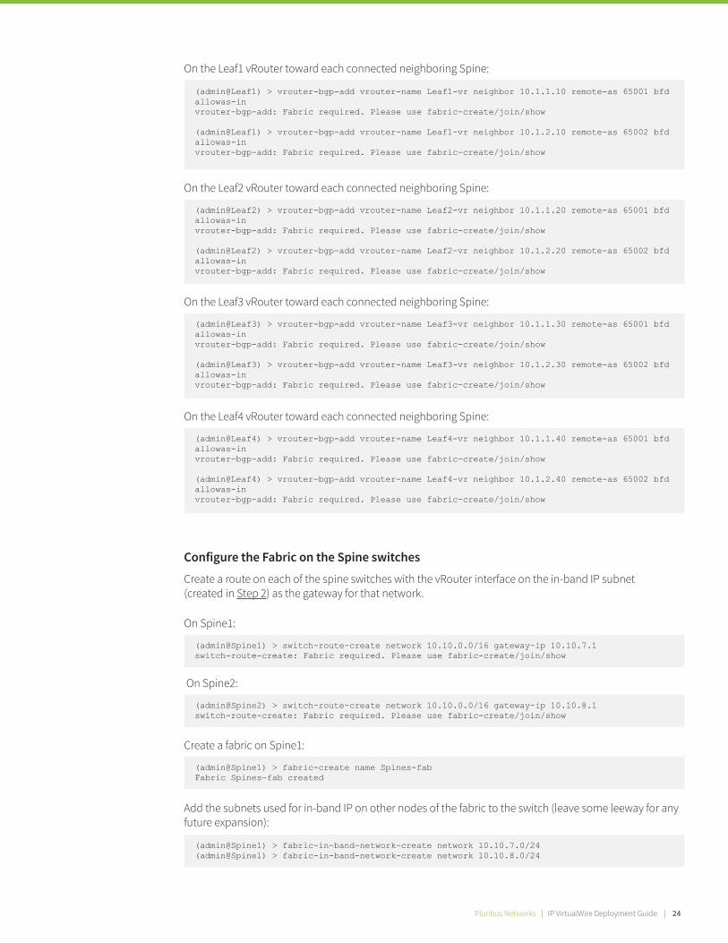
On the Leaf1 vRouter toward each connected neighboring Spine:
(admin@Leaf1) > vrouter-bgp-add vrouter-name Leaf1-vr neighbor 10.1.1.10 remote-as 65001 bfd allowas-invrouter-bgp-add: Fabric required. Please use fabric-create/join/show
(admin@Leaf1) > vrouter-bgp-add vrouter-name Leaf1-vr neighbor 10.1.2.10 remote-as 65002 bfd allowas-invrouter-bgp-add: Fabric required. Please use fabric-create/join/show
On the Leaf2 vRouter toward each connected neighboring Spine:
(admin@Leaf2) > vrouter-bgp-add vrouter-name Leaf2-vr neighbor 10.1.1.20 remote-as 65001 bfd allowas-invrouter-bgp-add: Fabric required. Please use fabric-create/join/show
(admin@Leaf2) > vrouter-bgp-add vrouter-name Leaf2-vr neighbor 10.1.2.20 remote-as 65002 bfd allowas-invrouter-bgp-add: Fabric required. Please use fabric-create/join/show
On the Leaf3 vRouter toward each connected neighboring Spine:
(admin@Leaf3) > vrouter-bgp-add vrouter-name Leaf3-vr neighbor 10.1.1.30 remote-as 65001 bfd allowas-invrouter-bgp-add: Fabric required. Please use fabric-create/join/show
(admin@Leaf3) > vrouter-bgp-add vrouter-name Leaf3-vr neighbor 10.1.2.30 remote-as 65002 bfd allowas-invrouter-bgp-add: Fabric required. Please use fabric-create/join/show
On the Leaf4 vRouter toward each connected neighboring Spine:
(admin@Leaf4) > vrouter-bgp-add vrouter-name Leaf4-vr neighbor 10.1.1.40 remote-as 65001 bfd allowas-invrouter-bgp-add: Fabric required. Please use fabric-create/join/show
(admin@Leaf4) > vrouter-bgp-add vrouter-name Leaf4-vr neighbor 10.1.2.40 remote-as 65002 bfd allowas-invrouter-bgp-add: Fabric required. Please use fabric-create/join/show
On Spine1:
(admin@Spine1) > switch-route-create network 10.10.0.0/16 gateway-ip 10.10.7.1switch-route-create: Fabric required. Please use fabric-create/join/show
On Spine2:
(admin@Spine2) > switch-route-create network 10.10.0.0/16 gateway-ip 10.10.8.1switch-route-create: Fabric required. Please use fabric-create/join/show
Create a fabric on Spine1:
(admin@Spine1) > fabric-create name Spines-fabFabric Spines-fab created
Add the subnets used for in-band IP on other nodes of the fabric to the switch (leave some leeway for any future expansion):
(admin@Spine1) > fabric-in-band-network-create network 10.10.7.0/24(admin@Spine1) > fabric-in-band-network-create network 10.10.8.0/24
Configure the Fabric on the Spine switches Create a route on each of the spine switches with the vRouter interface on the in-band IP subnet (created in Step 2) as the gateway for that network.
Pluribus Networks | IP VirtualWire Deployment Guide | 24Pluribus Networks | IP VirtualWire Deployment Guide | 26
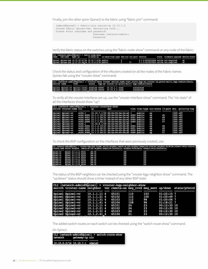
Finally, join the other spine (Spine2) to the fabric using “fabric-join” command:
Check the status and configuration of the vRouters created on all the nodes of the Fabric names Spines-fab using the “vrouter-show” command:
Verify the fabric status on the switches using the “fabric-node-show” command on any node of the fabric:
(admin@Spine2) > fabric-join switch-ip 10.10.7.2Joined fabric Spines-fab. Restarting nvOS...Please enter username and password: Username (network-admin): Password:
To verify all the vrouter-interfaces are up, use the “vrouter-interface-show” command. The “nic-state” of all the interfaces should show “up”:
To check the BGP configuration on the interfaces that were previously created, use:
The status of the BGP neighbors can be checked using the “vrouter-bgp-neighbor-show” command. The “up/down” status should show a timer instead of any other BGP state:
The added switch-routes on each switch can be checked using the “switch-route-show” command.
On Spine1:
25 | Pluribus Networks | IP VirtualWire Deployment Guide

On Spine2:
The subnets that are part of the fabric communication can be verified using the following command:
On Leaf1:
(admin@Leaf1) > switch-route-create network 10.5.0.0/16 gateway-ip 10.5.1.1switch-route-create: Fabric required. Please use fabric-create/join/show
On Leaf2:
(admin@Leaf2) > switch-route-create network 10.5.0.0/16 gateway-ip 10.5.2.1switch-route-create: Fabric required. Please use fabric-create/join/show
On Leaf3:
(admin@Leaf3) > switch-route-create network 10.5.0.0/16 gateway-ip 10.5.3.1switch-route-create: Fabric required. Please use fabric-create/join/show
On Leaf4:
Then, create an in-band fabric on one of the leaf switches.
(admin@Leaf4) > switch-route-create network 10.5.0.0/16 gateway-ip 10.5.4.1switch-route-create: Fabric required. Please use fabric-create/join/show
On Leaf1:
(admin@Leaf1) > fabric-create name IP-VirtualWire-fabFabric IP-VirtualWire-fab created
Join the fabric created on Leaf1 from the other leaf switches using the “fabric-join” command.
On Leaf2:
(admin@Leaf2) > fabric-join switch-ip 10.5.1.2Joined fabric IP-VirtualWire-fab. Restarting nvOS...Please enter username and password: Username (network-admin): Password:
Add the subnets used for in-band IP on other nodes of the fabric to the switch (leave some leeway for any future expansion):
(admin@Leaf1) > fabric-in-band-network-create network 10.5.0.0/16
Configure the Fabric on the Leaf switches Similar to above process, form a Fabric that spans the leaf switches.
First, on each leaf switch create a route that uses the vRouter interface’s address as default gateway for the subnet that contains the in-band IP address.
Pluribus Networks | IP VirtualWire Deployment Guide | 26Pluribus Networks | IP VirtualWire Deployment Guide | 28
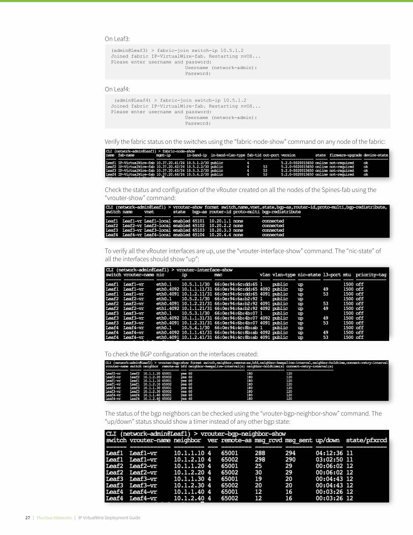
On Leaf3:
(admin@Leaf3) > fabric-join switch-ip 10.5.1.2Joined fabric IP-VirtualWire-fab. Restarting nvOS...Please enter username and password: Username (network-admin): Password:
On Leaf4: (admin@Leaf4) > fabric-join switch-ip 10.5.1.2Joined fabric IP-VirtualWire-fab. Restarting nvOS...Please enter username and password: Username (network-admin): Password:
Verify the fabric status on the switches using the “fabric-node-show” command on any node of the fabric:
Check the status and configuration of the vRouter created on all the nodes of the Spines-fab using the “vrouter-show” command:
To check the BGP configuration on the interfaces created:
To verify all the vRouter interfaces are up, use the “vrouter-interface-show” command. The “nic-state” of all the interfaces should show “up”:
The status of the bgp neighbors can be checked using the “vrouter-bgp-neighbor-show” command. The “up/down” status should show a timer instead of any other bgp state:
27 | Pluribus Networks | IP VirtualWire Deployment Guide

The added switch-routes on each switch can be checked using the “switch-route-show” command.
On Leaf2:
On Leaf1:
For the Leaf fabric:
(admin@Spine1) > vle-transparent-modify mode enable
(admin@Leaf1) > vle-transparent-modify mode enable
To check the vLE transparency status setting for the fabric, use the following command:
(admin@Leaf-01) > vle-transparent-show
To disable the error transparency:
(admin@Leaf-01) > vle-transparent-modify mode disable
3. Errored and Runt Packet Transparency Note that in the Netvisor CLI (or REST API) an IP VirtualWire service is referred to as Virtual Link Extension or “vLE”.
Transparency allows CRC errors and runt packets to be passed through between di�erent nodes of the fabric. With Pluribus Netvisor ONE IP VirtualWire transparency can be enabled on all the platforms using a single fabric-wide command.
The transparency feature should be enabled on both the leaf and spine fabrics. If the deployment is a brownfield scenario, third-party spine switches might drop the errored/runt packets if they do not support a passthrough capability for those packets.
For the Spine fabric:
On Leaf3:
On Leaf4:
The subnets that are part of the fabric communication can be verified using the following command:
Pluribus Networks | IP VirtualWire Deployment Guide | 28Pluribus Networks | IP VirtualWire Deployment Guide | 30
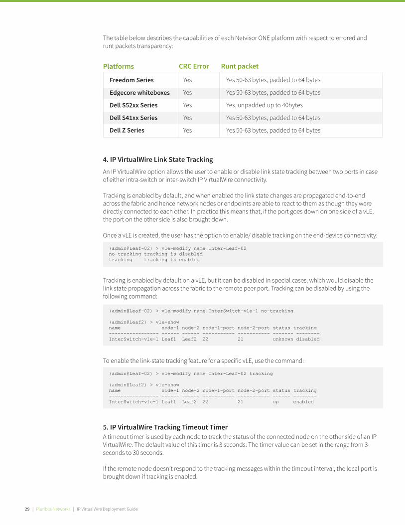
The table below describes the capabilities of each Netvisor ONE platform with respect to errored and runt packets transparency:
(admin@Leaf-02) > vle-modify name Inter-Leaf-02no-tracking tracking is disabledtracking tracking is enabled
(admin@Leaf-02) > vle-modify name InterSwitch-vle-1 no-tracking
(admin@Leaf2) > vle-showname node-1 node-2 node-1-port node-2-port status tracking----------------- ------ ------ ----------- ----------- ------- --------InterSwitch-vle-1 Leaf1 Leaf2 22 21 unknown disabled
Yes
Yes
Yes
Yes
Yes
Freedom Series
Edgecore whiteboxes
Dell S52xx Series
Dell S41xx Series
Dell Z Series
Platforms CRC Error
Yes 50-63 bytes, padded to 64 bytes
Yes 50-63 bytes, padded to 64 bytes
Yes, unpadded up to 40bytes
Yes 50-63 bytes, padded to 64 bytes
Yes 50-63 bytes, padded to 64 bytes
Runt packet
4. IP VirtualWire Link State Tracking An IP VirtualWire option allows the user to enable or disable link state tracking between two ports in case of either intra-switch or inter-switch IP VirtualWire connectivity.
Tracking is enabled by default, and when enabled the link state changes are propagated end-to-end across the fabric and hence network nodes or endpoints are able to react to them as though they were directly connected to each other. In practice this means that, if the port goes down on one side of a vLE, the port on the other side is also brought down.
Once a vLE is created, the user has the option to enable/ disable tracking on the end-device connectivity:
5. IP VirtualWire Tracking Timeout Timer A timeout timer is used by each node to track the status of the connected node on the other side of an IP VirtualWire. The default value of this timer is 3 seconds. The timer value can be set in the range from 3 seconds to 30 seconds.
If the remote node doesn’t respond to the tracking messages within the timeout interval, the local port is brought down if tracking is enabled.
Tracking is enabled by default on a vLE, but it can be disabled in special cases, which would disable the link state propagation across the fabric to the remote peer port. Tracking can be disabled by using the following command:
(admin@Leaf-02) > vle-modify name Inter-Leaf-02 tracking
(admin@Leaf2) > vle-showname node-1 node-2 node-1-port node-2-port status tracking----------------- ------ ------ ----------- ----------- ------ --------InterSwitch-vle-1 Leaf1 Leaf2 22 21 up enabled
To enable the link-state tracking feature for a specific vLE, use the command:
29 | Pluribus Networks | IP VirtualWire Deployment Guide
To check the value of the timer:
(admin@Leaf-02) > system-settings-show format vle-tracking-timeout,vle-tracking-timeout: 3vle-tracking-timeout: 3vle-tracking-timeout: 3
(admin@Leaf1) > vlan-create id 3999 scope local ports none
(admin@Leaf2) > vlan-create id 3999 scope local ports none
(admin@Leaf3) > vlan-create id 3999 scope local ports none
(admin@Leaf4) > vlan-create id 3999 scope local ports none
To change the value of the timer:
(admin@Leaf-02) > system-settings-modify vle-tracking-timeoutnumber between 3 and 30(admin@Leaf-02) > system-settings-modify vle-tracking-timeout 10
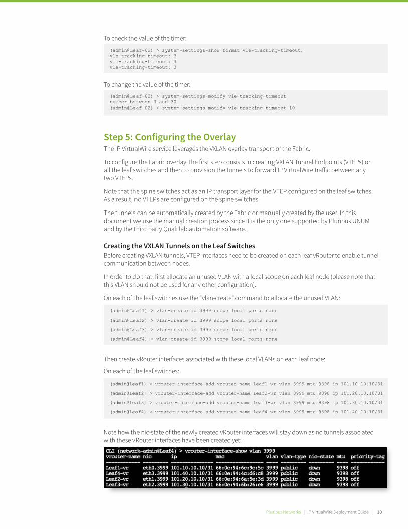
Then create vRouter interfaces associated with these local VLANs on each leaf node:
On each of the leaf switches:
Note how the nic-state of the newly created vRouter interfaces will stay down as no tunnels associated with these vRouter interfaces have been created yet:
(admin@Leaf1) > vrouter-interface-add vrouter-name Leaf1-vr vlan 3999 mtu 9398 ip 101.10.10.10/31
(admin@Leaf2) > vrouter-interface-add vrouter-name Leaf2-vr vlan 3999 mtu 9398 ip 101.20.10.10/31
(admin@Leaf3) > vrouter-interface-add vrouter-name Leaf3-vr vlan 3999 mtu 9398 ip 101.30.10.10/31
(admin@Leaf4) > vrouter-interface-add vrouter-name Leaf4-vr vlan 3999 mtu 9398 ip 101.40.10.10/31
Creating the VXLAN Tunnels on the Leaf Switches Before creating VXLAN tunnels, VTEP interfaces need to be created on each leaf vRouter to enable tunnel communication between nodes.
In order to do that, first allocate an unused VLAN with a local scope on each leaf node (please note that this VLAN should not be used for any other configuration).
On each of the leaf switches use the “vlan-create” command to allocate the unused VLAN:
Step 5: Configuring the Overlay The IP VirtualWire service leverages the VXLAN overlay transport of the Fabric.
To configure the Fabric overlay, the first step consists in creating VXLAN Tunnel Endpoints (VTEPs) on all the leaf switches and then to provision the tunnels to forward IP VirtualWire tra�ic between any two VTEPs.
Note that the spine switches act as an IP transport layer for the VTEP configured on the leaf switches. As a result, no VTEPs are configured on the spine switches.
The tunnels can be automatically created by the Fabric or manually created by the user. In this document we use the manual creation process since it is the only one supported by Pluribus UNUM and by the third party Quali lab automation so�ware.
Pluribus Networks | IP VirtualWire Deployment Guide | 30Pluribus Networks | IP VirtualWire Deployment Guide | 32
We are now ready to create the tunnels from each leaf node to all other leaf nodes.
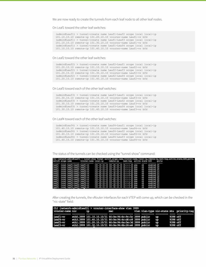
The status of the tunnels can be checked using the “tunnel-show” command:
(admin@Leaf1) > tunnel-create name Leaf1-Leaf2 scope local local-ip 101.10.10.10 remote-ip 101.20.10.10 vrouter-name Leaf1-vr bfd(admin@Leaf1) > tunnel-create name Leaf1-Leaf3 scope local local-ip 101.10.10.10 remote-ip 101.30.10.10 vrouter-name Leaf1-vr bfd(admin@Leaf1) > tunnel-create name Leaf1-Leaf4 scope local local-ip 101.10.10.10 remote-ip 101.40.10.10 vrouter-name Leaf1-vr bfd
On Leaf1 toward the other leaf switches:
(admin@Leaf2) > tunnel-create name Leaf2-Leaf1 scope local local-ip 101.20.10.10 remote-ip 101.10.10.10 vrouter-name Leaf2-vr bfd(admin@Leaf2) > tunnel-create name Leaf2-Leaf3 scope local local-ip 101.20.10.10 remote-ip 101.30.10.10 vrouter-name Leaf2-vr bfd(admin@Leaf2) > tunnel-create name Leaf2-Leaf4 scope local local-ip 101.20.10.10 remote-ip 101.40.10.10 vrouter-name Leaf2-vr bfd
On Leaf2 toward the other leaf switches:
(admin@Leaf3) > tunnel-create name Leaf3-Leaf1 scope local local-ip 101.30.10.10 remote-ip 101.10.10.10 vrouter-name Leaf3-vr bfd(admin@Leaf3) > tunnel-create name Leaf3-Leaf2 scope local local-ip 101.30.10.10 remote-ip 101.20.10.10 vrouter-name Leaf3-vr bfd(admin@Leaf3) > tunnel-create name Leaf3-Leaf4 scope local local-ip 101.30.10.10 remote-ip 101.40.10.10 vrouter-name Leaf3-vr bfd
On Leaf3 toward each of the other leaf switches:
(admin@Leaf4) > tunnel-create name Leaf4-Leaf1 scope local local-ip 101.40.10.10 remote-ip 101.10.10.10 vrouter-name Leaf4-vr bfd(admin@Leaf4) > tunnel-create name Leaf4-Leaf2 scope local local-ip 101.40.10.10 remote-ip 101.20.10.10 vrouter-name Leaf4-vr bfd(admin@Leaf4) > tunnel-create name Leaf4-Leaf3 scope local local-ip 101.40.10.10 remote-ip 101.30.10.10 vrouter-name Leaf4-vr bfd
On Leaf4 toward each of the other leaf switches:
A�er creating the tunnels, the vRouter interfaces for each VTEP will come up, which can be checked in the “nic-state” field:
31 | Pluribus Networks | IP VirtualWire Deployment Guide

Step 6: Configure IP VirtualWire Connectivity At this point the underlay and overlay networks of the Fabric are ready to support the provisioning of IP VirtualWire services.
The configuration can be carried out in multiple ways including CLI, REST APIs, UNUM IP VirtualWire dashboard, or by using the third party Quali LaaS (Lab-as-a-Service).
In the next few sections, we will review how to create IP VirtualWire services with CLI, UNUM and the Quali so�ware.
Create an overlay VLAN with a local scope on the Leaf1 to carry the tra�ic of the IP VirtualWire. Note how the “vxlan-mode” must be set to “transparent”. To implement the connection shown in Figure 3, follow these steps:
(admin@Leaf1) > vlan-create id 1000 scope local vxlan 501000 vxlan-mode transparent ports 21,23
Configuring IP VirtualWire Using the CLI Note that in Netvisor CLI or REST API an IP VirtualWire service is referred to as Virtual Link Extension or “vLE”.
Creating Intra-switch IP VirtualWire Connectivity VirtualWire connectivity can be established between two DUTs that are connected to the same leaf switch using local configuration only, as there is no need to use inter-switch communication.
Create a connection between ebc-server-2 port A to ebc-server-4 port B which are connected to Leaf1 shown in the diagram below.
Figure 3: Intra-Switch VirtualWire connectivity
Create a vLE to associate ports 21 and 23 on Leaf1:
(admin@Leaf1) > vle-create name IntraSwitch-vle-1 node-1 Leaf1 node-2 Leaf1 node-1-port 21 node2-port 23
Pluribus Networks | IP VirtualWire Deployment Guide | 32Pluribus Networks | IP VirtualWire Deployment Guide | 34

Next, following the same steps, we create a second connection between ebc-server-2 port B and sw12 port 5 connected to Leaf1 shown in the diagram below.
Second, delete the VLAN associated with this vLE:
(admin@Leaf1) > vlan-create id 1001 scope local vxlan 501001 vxlan-mode transparent ports 22,5
(admin@Leaf1) > vle-create name IntraSwitch-vle-2 node-1 Leaf1 node-2 Leaf1 node-1-port 5 node-2-port 22
(admin@Leaf1) > vle-delete name IntraSwitch-vle-2
(admin@Leaf1) > vlan-delete id 1001
Figure 4: Intra-Switch VirtualWire connectivity
Deleting Intra-switch VirtualWire Connectivity
Intra-switch IP VirtualWire services can be deleted in two steps:
First, delete the created vLE using the command “vle-delete”:
Creating Inter-switch VirtualWire Connectivity
An IP VirtualWire service can be established between two DUTs as long as they are connected to the same Fabric overlay.
33 | Pluribus Networks | IP VirtualWire Deployment Guide

The switches can then be rebooted together using the command fabric-upgrade-finish. Or they can be manually rebooted one at a time using the switch-reboot command on each switch.
Instead, if the auto-finish option was selected, then all the switches automatically reboot a�er the installation.
Multiple IP VirtualWire connections can be made between any two endpoints over the same tunnel. This scenario is illustrated in the Figure 5 below:
In the following example, we establish connectivity between two pairs of endpoints using the same VXLAN tunnel to demonstrate how to share a common tunnel.
With a procedure that is similar to the intra-switch vLE configuration case, first we create a local VLAN on each of the end nodes, and then we associate it to the same VXLAN ID on each node.
To create a connection between ebc-server-2 port B and ebc-server-4 port A from Figure 5 above, first create a local VLAN with the “vxlan-mode transparent” option:
(admin@Leaf1) > vlan-create id 1050 scope local vxlan 501050 vxlan-mode transparent ports 22
Figure 5: Inter-Switch VirtualWire connectivity
On Leaf1:
(admin@Leaf2) > vlan-create id 1050 scope local vxlan 501050 vxlan-mode transparent ports 21
On Leaf2:
(admin@Leaf2) > tunnel-vxlan-add name Leaf2-Leaf1 vxlan 501050
On Leaf2:
The vxlan added to the tunnel can be checked using the command “tunnel-vxlan-show”:
(admin@Leaf1) > tunnel-vxlan-add name Leaf1-Leaf2 vxlan 501050
Next, add the VXLAN ID to the tunnels between the two nodes:
On Leaf1:
Pluribus Networks | IP VirtualWire Deployment Guide | 34Pluribus Networks | IP VirtualWire Deployment Guide | 36

Finally, configure a vLE and add the two end-point ports on each node:
Now we create a connection between sw12 port 5 to sw13 port 6 from Figure 5, use:
On Leaf1:
On Leaf2:
(admin@Leaf1) > vlan-create id 1051 scope local vxlan 501051 vxlan-mode transparent ports 5
Next add the VXLAN ID to the tunnels between the two nodes:
On Leaf1:
(admin@Leaf1) > tunnel-vxlan-add name Leaf1-Leaf3 vxlan 501051
(admin@Leaf2) > vle-create name InterSwitch-vle-1 node-1 Leaf1 node-2 Leaf2 node-1-port 22 node-2-port 21
Finally, configure a vLE and add the two end-point ports on each node:
The information on all the VXLAN IDs that are added to the tunnels between the nodes can be displayed using the command “tunnel-vxlan-show”:
(admin@Leaf1) > vle-create name InterSwitch-vle-2 node-1 Leaf1 node-2 Leaf2node-1-port 5 node-2-port 6
(admin@Leaf3) > vlan-create id 1051 scope local vxlan 501051 vxlan-mode transparent ports 6
On Leaf2:
(admin@Leaf3) > tunnel-vxlan-add name Leaf3-Leaf1 vxlan 501051
Second, remove the VXLAN ID from the tunnels of both the switches:
On Leaf1:
(admin@Leaf1) > tunnel-vxlan-remove name Leaf1-Leaf3 vxlan 501051
(admin@Leaf3) > vle-delete name InterSwitch-vle-1
Deleting Inter-switch VirtualWire Connectivity
An IP VirtualWire connection between DUTs can be deleted in three simple steps.
First, delete the vLE object using the command “vle-delete”:
35 | Pluribus Networks | IP VirtualWire Deployment Guide

On Leaf3:(admin@Leaf3) > tunnel-vxlan-remove name Leaf3-Leaf1 vxlan 501051
(admin@Leaf1) > vlan-delete id 1051
(admin@Leaf3) > vlan-delete id 1051
On Leaf3:
Finally, delete the VLAN previously created for the VirtualWire connection on both fabric nodes:
On Leaf1:
To create a connection between two endpoints, select the switch that has one of the endpoints directly connected (once selected, the node is highlighted). Select the second switch by holding the “ctrl” (Windows) or “command” (Mac) key.
Upon clicking on the second device (which can be the same node in case of intra-switch vLE) the following dialogue box appears:
Figure 6: Default view for the IP VirtualWire page in UNUM
Figure 7: Making a virtual connectivity using UNUM
Figure 8: Pop-up to create a virtual connection
Configuring IP VirtualWire Using UNUM
UNUM utilizes the REST API infrastructure of Netvisor ONE to automate the provisioning of IP VirtualWire services.
The “IP VirtualWire” dashboard shows all the fabric switches in the fabric in a wheel diagram.
Pluribus Networks | IP VirtualWire Deployment Guide | 36Pluribus Networks | IP VirtualWire Deployment Guide | 38
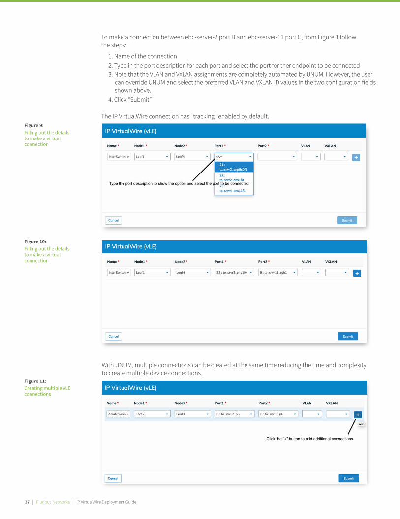
To make a connection between ebc-server-2 port B and ebc-server-11 port C, from Figure 1 follow the steps:
With UNUM, multiple connections can be created at the same time reducing the time and complexity to create multiple device connections.
The IP VirtualWire connection has “tracking” enabled by default.
1. Name of the connection 2. Type in the port description for each port and select the port for ther endpoint to be connected3. Note that the VLAN and VXLAN assignments are completely automated by UNUM. However, the user can override UNUM and select the preferred VLAN and VXLAN ID values in the two configuration fields shown above.4. Click “Submit”
Figure 9: Filling out the details to make a virtual connection
Figure 10: Filling out the details to make a virtual connection
Figure 11: Creating multiple vLE connections
37 | Pluribus Networks | IP VirtualWire Deployment Guide
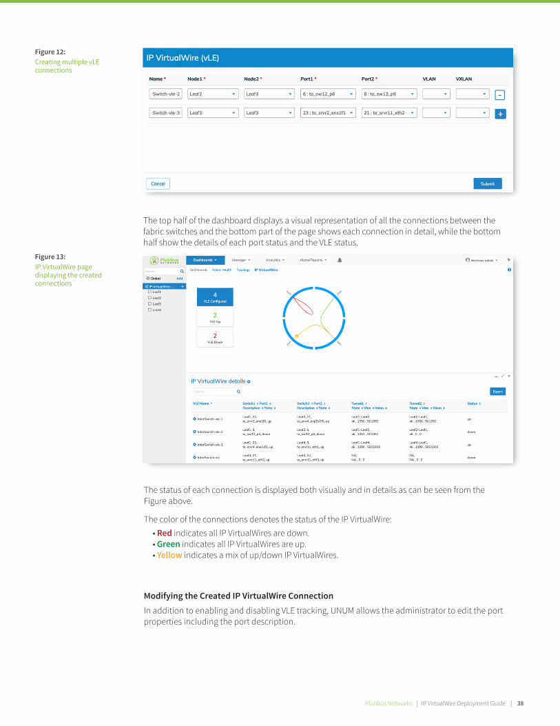
Figure 12: Creating multiple vLE connections
The top half of the dashboard displays a visual representation of all the connections between the fabric switches and the bottom part of the page shows each connection in detail, while the bottom half show the details of each port status and the VLE status.
The status of each connection is displayed both visually and in details as can be seen from the Figure above.
The color of the connections denotes the status of the IP VirtualWire: • Red indicates all IP VirtualWires are down. • Green indicates all IP VirtualWires are up. • Yellow indicates a mix of up/down IP VirtualWires.
Figure 13: IP VirtualWire page displaying the created connections
Modifying the Created IP VirtualWire Connection
In addition to enabling and disabling VLE tracking, UNUM allows the administrator to edit the port properties including the port description.
Pluribus Networks | IP VirtualWire Deployment Guide | 38Pluribus Networks | IP VirtualWire Deployment Guide | 40
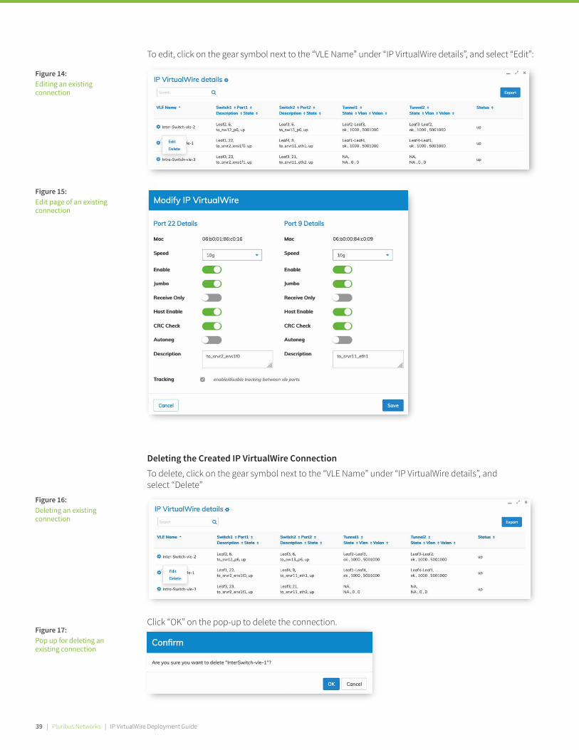
To edit, click on the gear symbol next to the “VLE Name” under “IP VirtualWire details”, and select “Edit”:
Click “OK” on the pop-up to delete the connection.
Figure 14: Editing an existing connection
Figure 15: Edit page of an existing connection
Figure 16: Deleting an existing connection
Deleting the Created IP VirtualWire Connection
To delete, click on the gear symbol next to the “VLE Name” under “IP VirtualWire details”, and select “Delete”
Figure 17: Pop up for deleting an existing connection
39 | Pluribus Networks | IP VirtualWire Deployment Guide
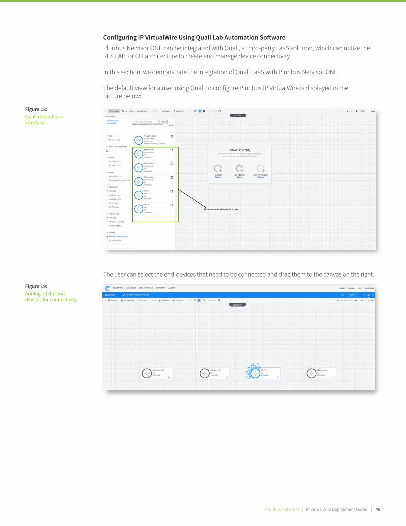
The user can select the end-devices that need to be connected and drag them to the canvas on the right.
Figure 18: Quali default user- interface
Configuring IP VirtualWire Using Quali Lab Automation So�ware
Pluribus Netvisor ONE can be integrated with Quali, a third-party LaaS solution, which can utilize the REST API or CLI architecture to create and manage device connectivity.
In this section, we demonstrate the integration of Quali LaaS with Pluribus Netvisor ONE.
The default view for a user using Quali to configure Pluribus IP VirtualWire is displayed in the picture below:
Figure 19: Adding all the end- devices for connectivity
Pluribus Networks | IP VirtualWire Deployment Guide | 40
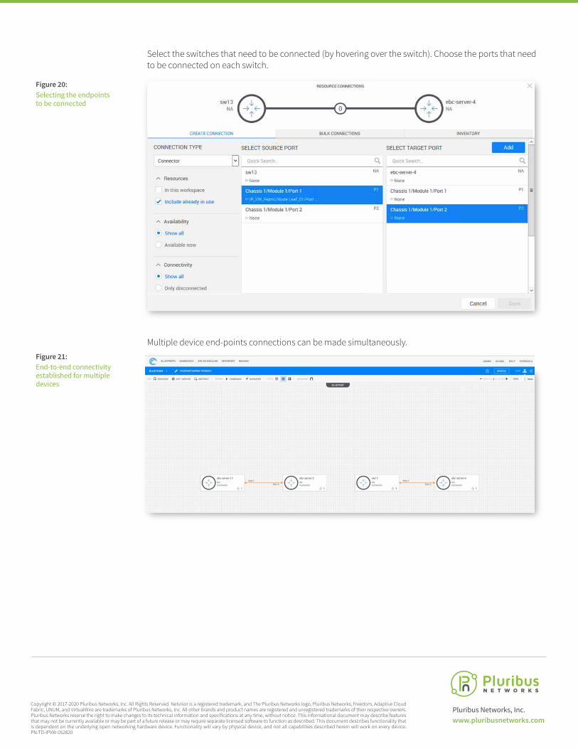
Copyright © 2017-2020 Pluribus Networks, Inc. All Rights Reserved. Netvisor is a registered trademark, and The Pluribus Networks logo, Pluribus Networks, Freedom, Adaptive Cloud Fabric, UNUM, and VirtualWire are trademarks of Pluribus Networks, Inc. All other brands and product names are registered and unregistered trademarks of their respective owners. Pluribus Networks reserve the right to make changes to its technical information and specifications at any time, without notice. This informational document may describe features that may not be currently available or may be part of a future release or may require separate licensed so�ware to function as described. This document describes functionality that is dependent on the underlying open networking hardware device. Functionality will vary by physical device, and not all capabilities described herein will work on every device. PN-TD-IPVW-052820
Select the switches that need to be connected (by hovering over the switch). Choose the ports that need to be connected on each switch.
Pluribus Networks, Inc. www.pluribusnetworks.com
Figure 20: Selecting the endpoints to be connected
Multiple device end-points connections can be made simultaneously.Figure 21: End-to-end connectivity established for multiple devices
Related Documents